first lecture highway classification
TRANSCRIPT

Dr. Duraid M Abd Civil Engineering 2019
60
1.6.5 Vertical alignment
Vertical alignment specifies the elevation of points along a roadway. The
elevation of these roadway points are usually determined by the need to provide
an acceptable level of driver safety, driver comfort and proper drainage. A
primary concern in vertical alignment is establishing the transition of roadway
elevations between two grades. This transition is achieved by means of a
vertical curve. One of the most important factors that affect the design of this
alignment is the topography of the area through which the proposed road is
being passing as presented in Figures 1.30 and 1.31.
Vertical curves are usually parabolic in shape and can be broadly classified into
crest vertical curves and sag vertical curves as illustrated in Figures 1.32 and
1.33.
Figure 1.30: Examples of vertical curves
Dr. Duraid M Abd Civil Engineering 2019
61
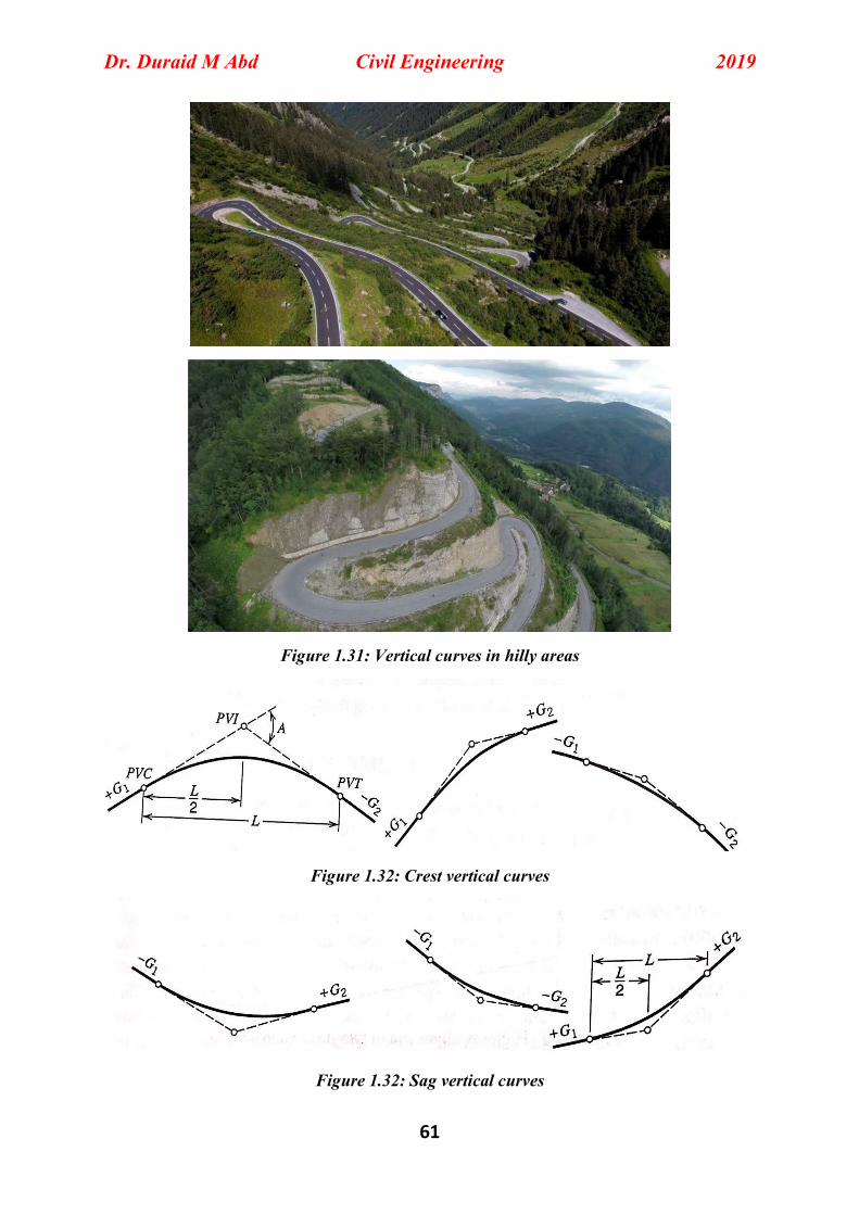
Figure 1.31: Vertical curves in hilly areas
Figure 1.32: Crest vertical curves
Figure 1.32: Sag vertical curves
Dr. Duraid M Abd Civil Engineering 2019
62
1.6.5.1 Maximum grade
Passenger cars are normally less affected by the step grade as compared with
the truck or heavy vehicle. Generally, the grade has a great effect on the heavy
truck vehicles where a reduction of speed occurs on these grades. It should be
noted that the selection of the grade value has a great influence on the volume
of earthwork. To reduce this effect, it is customarily adopted to design the
highways in such a way that ensure a reduction in the earthwork quantities and
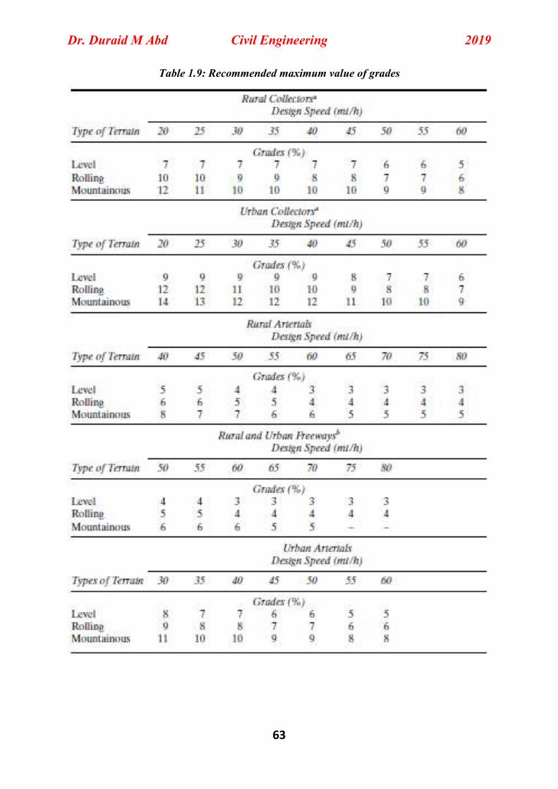
hence the cost of the project. Table 1.9 presents recommended maximum values
of grades with respect to types of terrain and road.
1.6.5.2 Minimum grade
The minimum grade is generally governed by adopted drainage requirements
for roadway being designed. A minimum grade of 0.3% is desirable for high
type pavements.
1.6.5.3 Critical length of grade
This critical length can be defined as the maximum length of upgrade on which
the design vehicle (almost heavy trucks) can run without a reasonable speed
reduction. Figure 1.33 is used to assess the critical length of grade. It should be noted
that a speed reduction curve of 15 Km/h is recommended to be used to find the critical length
of grade.
Dr. Duraid M Abd Civil Engineering 2019
63
Table 1.9: Recommended maximum value of grades

Dr. Duraid M Abd Civil Engineering 2019
64
Figure 1.33: Critical length of grade
1.6.5.4 Elements of vertical curves
Elements of vertical curves can be illustrate in Figure 1.34
Figure 1.34: Layout and parameters of vertical curve

Dr. Duraid M Abd Civil Engineering 2019
65
Where:
G1, G2: Grades of tangents %
L: Length of curve
E: External distance
BVC (PVC): beginning of vertical curve
EVC (PVT): End of vertical curve
PVI: point of vertical intersection
A: algebraic difference of grades, G1-G2
1.6.5.5 Properties of vertical curves
The determination of vertical curve elevations and elevation of critical points
could be computed based on the properties of parabola as shown in equation
y= ax2 + bx+ c ……………………………………………………………36
where
y = elevation of any point on curve.
x= distance from the point of vertical curvature.
a = rate of change of gradient.
b = initial grade
c= elevation of point of curvature
Rate of change of slope = the second derivative
First derivative = 2ax+b
Second derivative = 2a ………………………………………………………..37
But, the rate of change =(G2-G1)/100L ………………………………………..38
Equating Eq.37 and Eq.38 gives
2a= (G2-G1)/100L
Dr. Duraid M Abd Civil Engineering 2019
66
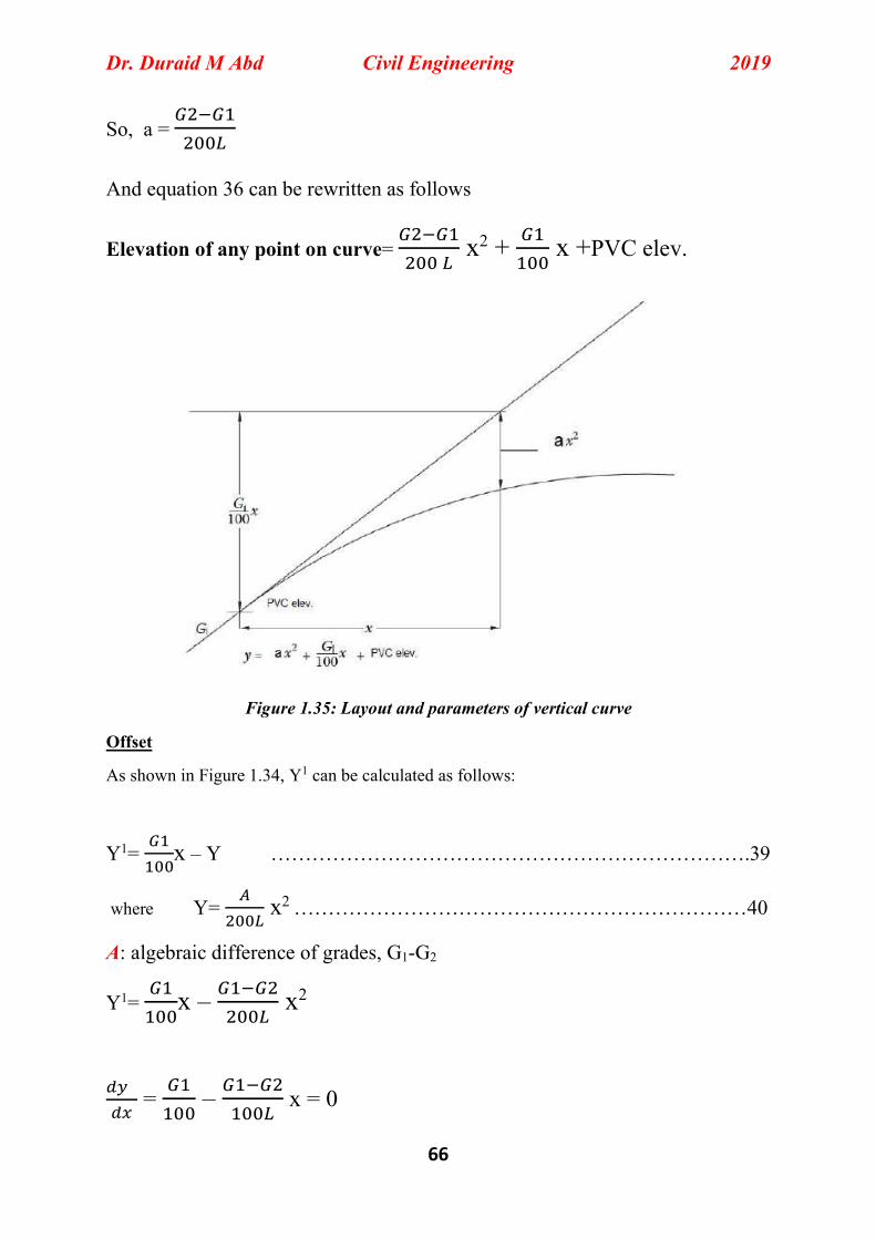
So, a =
And equation 36 can be rewritten as follows
Elevation of any point on curve=
x2 + x +PVC elev.
Figure 1.35: Layout and parameters of vertical curve
Offset
As shown in Figure 1.34, Y1 can be calculated as follows:
Y1= x – Y …………………………………………………………….39
where Y= x2 …………………………………………………………40
A: algebraic difference of grades, G1-G2
Y1= x – x2
= – x = 0

Dr. Duraid M Abd Civil Engineering 2019
67
X high/ low= L ………………………………………………………….41
External distance E from the point of vertical intersection (PVI) to the curve is
determined by substituting L/2 for x in Eq. Y= x2
E = ……………………………………………..………………………...42
BVC Station = PVI station - …………………………………………………..….43
EVC Station = BVC station + L ……………………………………………………44
BVC Elevation = PVI Elevation - ……………………………………………….45
EVC Elevation = PVI Elevation - ……………………………………………….46
1.6.5.6 Design Procedure for Crest and Sag Vertical Curves
Step 1. Determine the minimum length of curve to satisfy sight distance requirements and other criteria for sag curves (sight distance requirements, comfort requirements. appearance requirements, and drainage requirements. Step 2. Determine from the layout plans the station and elevation of the point where the grades intersect (PVI). Step 3. Compute the elevations of the beginning of vertical curve, (BVC) and the end of vertical curve (EVC). Step 4. Compute the offsets, Y, (Eq. 40) as the distance between the tangent and the curve. Usually equal distances of 20m (1 station) are used, beginning with the first whole station after the BVC. Step 5. Compute elevations on the curve for each station. Step 6. Compute the location and elevation of the highest (crest) or lowest (sag) point on the curve

Dr. Duraid M Abd Civil Engineering 2019
68
1.6.5.7 Determine the minimum length of curve When length of vertical curves needs to be computed, four scenarios/ criteria
should be taken in account. Those includes:
1. Sight distance requirements. 2. Comfort requirements. 3. Appearance requirements. 4. Drainage requirements
The first criteria is only used to design the crest vertical curve; whereas all
criteria are taken in account the process of design sag vertical curves.
1.6.5.7.1 Crest vertical Curves
As mentioned previously, crest vertical curves are commonly designed on the
basis of sight distance requirements. Two scenarios exist and controls the
design. These are when the length of curve is greater than the sight distance (L
> S) and when the length of curve is less than the sight distance. Figure 1.36
shows the first case which is the more poplar or common design option.
Figure 1.36: Crest vertical curves
Dr. Duraid M Abd Civil Engineering 2019
69
The following equations are used to compute minimum length of vertical curve
for both design option stated above:
When S is less than L
Lmin = √ √
……………………………………………………..47
When S is greater than L
Lmin = 2S - √ √
………………………………………………...48
Where:
L is length of vertical curve, m
A is algebraic difference in grades, %
S is sight distance, m
h1 is height of eye above roadway surface, m
h2 is height of object above roadway surface, m
Based on AASHTO’s G.D policy, the values of h1 and h2 are 1.08 and 0.6 m,
respectively. So by applying these values in equations above results, we get:
When S is less than L
Lmin = …………………………………………………………………….49
When S is greater than L
Lmin = 2S - ………………………………………………..........................50
Design controls: stopping sight distance
Equation 49 (for S is less than L) can be rewritten as follows;
L= K. A ……………………………………………………………………….51
Dr. Duraid M Abd Civil Engineering 2019
70
Where;
K = S2/ 658 …………………………………………………………………….52
And, K value represent the length of curve for each 1 degree change in the
grade.
It should be noted in practice that when S > L, the calculated minimum length
will be small and impractical for design consideration. Consequently, the
designer should adopt minimum of crest vertical curve of L=0.6V (where L and
V represent length of curve and design speed in Km/h, respectively) or use the
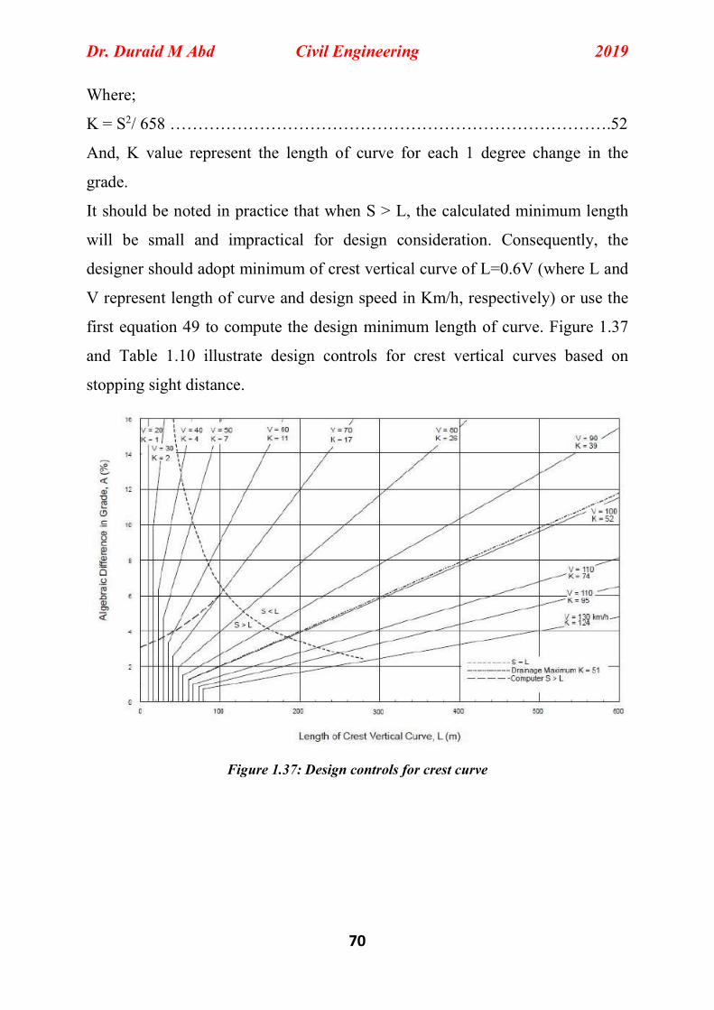
first equation 49 to compute the design minimum length of curve. Figure 1.37
and Table 1.10 illustrate design controls for crest vertical curves based on
stopping sight distance.
Figure 1.37: Design controls for crest curve
Dr. Duraid M Abd Civil Engineering 2019
71
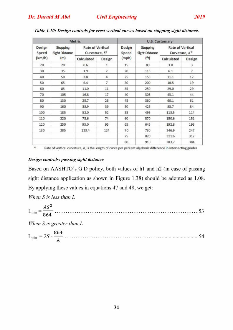
Table 1.10: Design controls for crest vertical curves based on stopping sight distance.
Design controls: passing sight distance
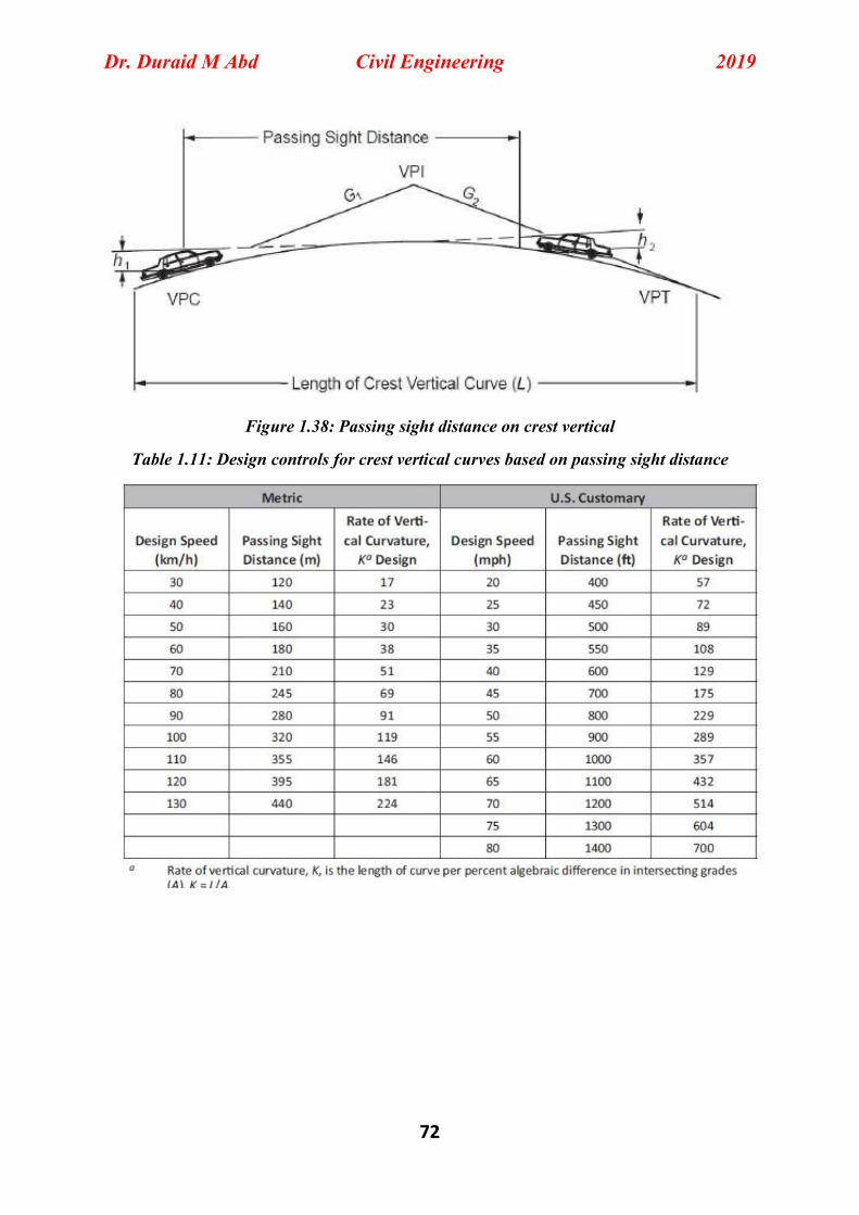
Based on AASHTO’s G.D policy, both values of h1 and h2 (in case of passing
sight distance application as shown in Figure 1.38) should be adopted as 1.08.
By applying these values in equations 47 and 48, we get:
When S is less than L
Lmin = …………………………………………………………………….53
When S is greater than L
Lmin = 2S - ………………………………………………..........................54
Dr. Duraid M Abd Civil Engineering 2019
72
Figure 1.38: Passing sight distance on crest vertical
Table 1.11: Design controls for crest vertical curves based on passing sight distance
Dr. Duraid M Abd Civil Engineering 2019
73
1.6.5.7.2 Sag vertical Curves
Having mentioned that the minimum length of sag vertical curve is governed by
four criteria, which include:
1. Sight distance requirements.
2. Comfort requirements.
3. Appearance requirements.
4. Drainage requirements
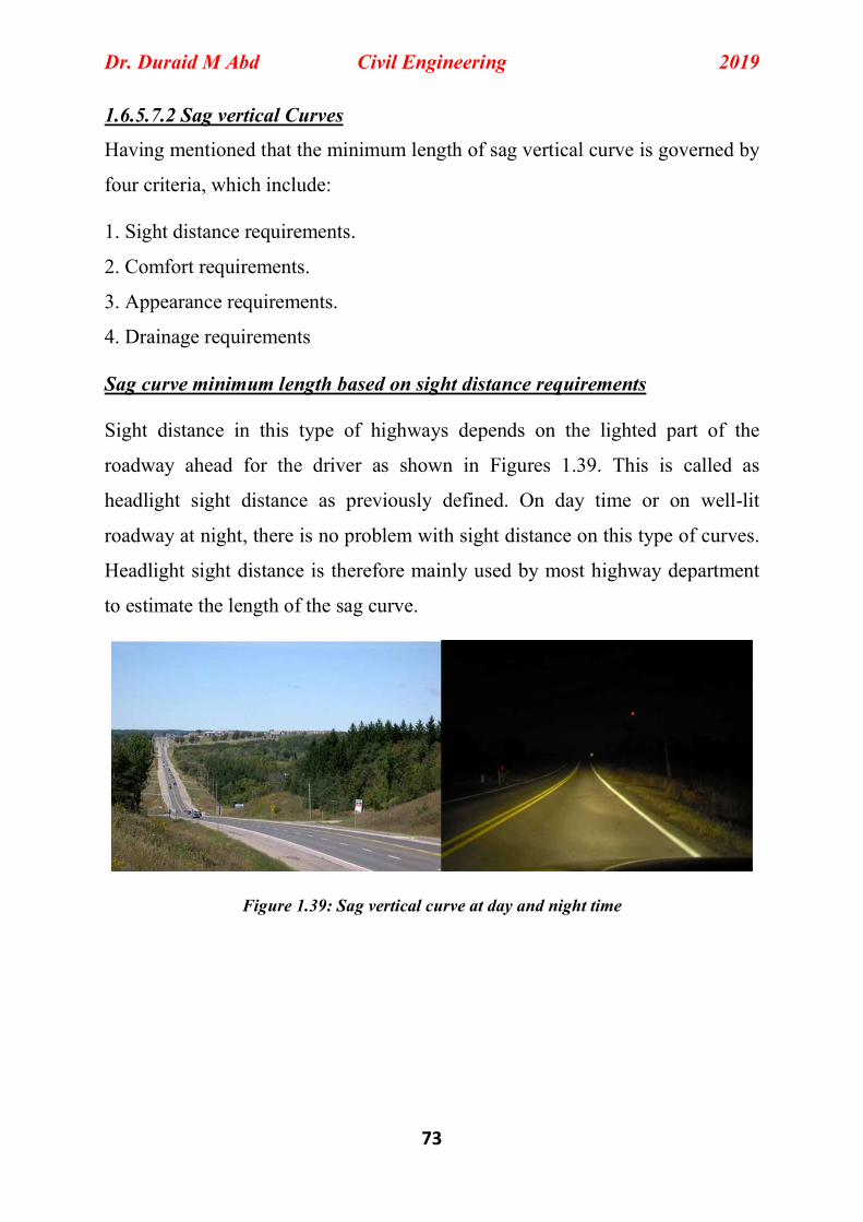
Sag curve minimum length based on sight distance requirements
Sight distance in this type of highways depends on the lighted part of the
roadway ahead for the driver as shown in Figures 1.39. This is called as
headlight sight distance as previously defined. On day time or on well-lit
roadway at night, there is no problem with sight distance on this type of curves.
Headlight sight distance is therefore mainly used by most highway department
to estimate the length of the sag curve.
Figure 1.39: Sag vertical curve at day and night time
Dr. Duraid M Abd Civil Engineering 2019
74
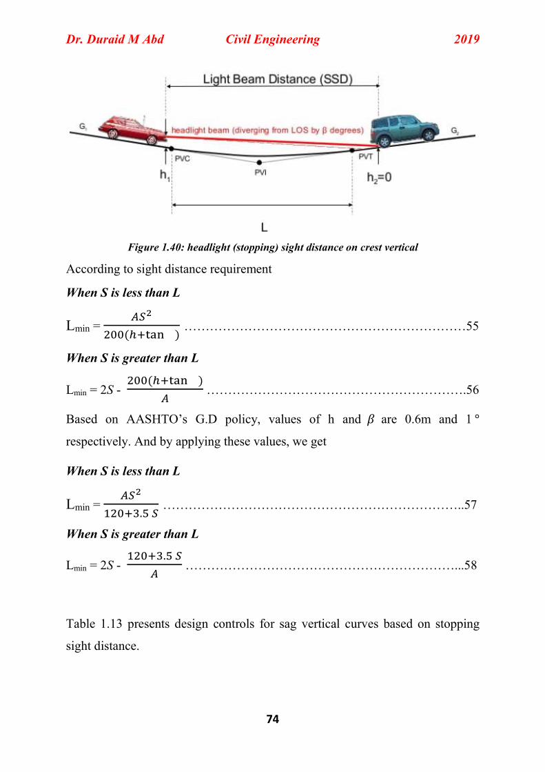
Figure 1.40: headlight (stopping) sight distance on crest vertical
According to sight distance requirement
When S is less than L
Lmin = ( )
…………………………………………………………55
When S is greater than L
Lmin = 2S - ( )
…………………………………………………….56
Based on AASHTO’s G.D policy, values of h and 𝛽 are 0.6m and 1 °
respectively. And by applying these values, we get
When S is less than L
Lmin = .
……………………………………………………………..57
When S is greater than L
Lmin = 2S - .
………………………………………………………...58
Table 1.13 presents design controls for sag vertical curves based on stopping
sight distance.
Dr. Duraid M Abd Civil Engineering 2019
75
Sag curve minimum length based on driver comfort
Unlike on crest vertical curves, vehicle on sag curve is under a combination of
gravitational and centrifugal forces. This combination may apply discomfort to
the driver on this type of curves. To satisfy this criterion, the minimum length of
curve should be estimated from the following formula.
L = ……………………………………………………………………….59
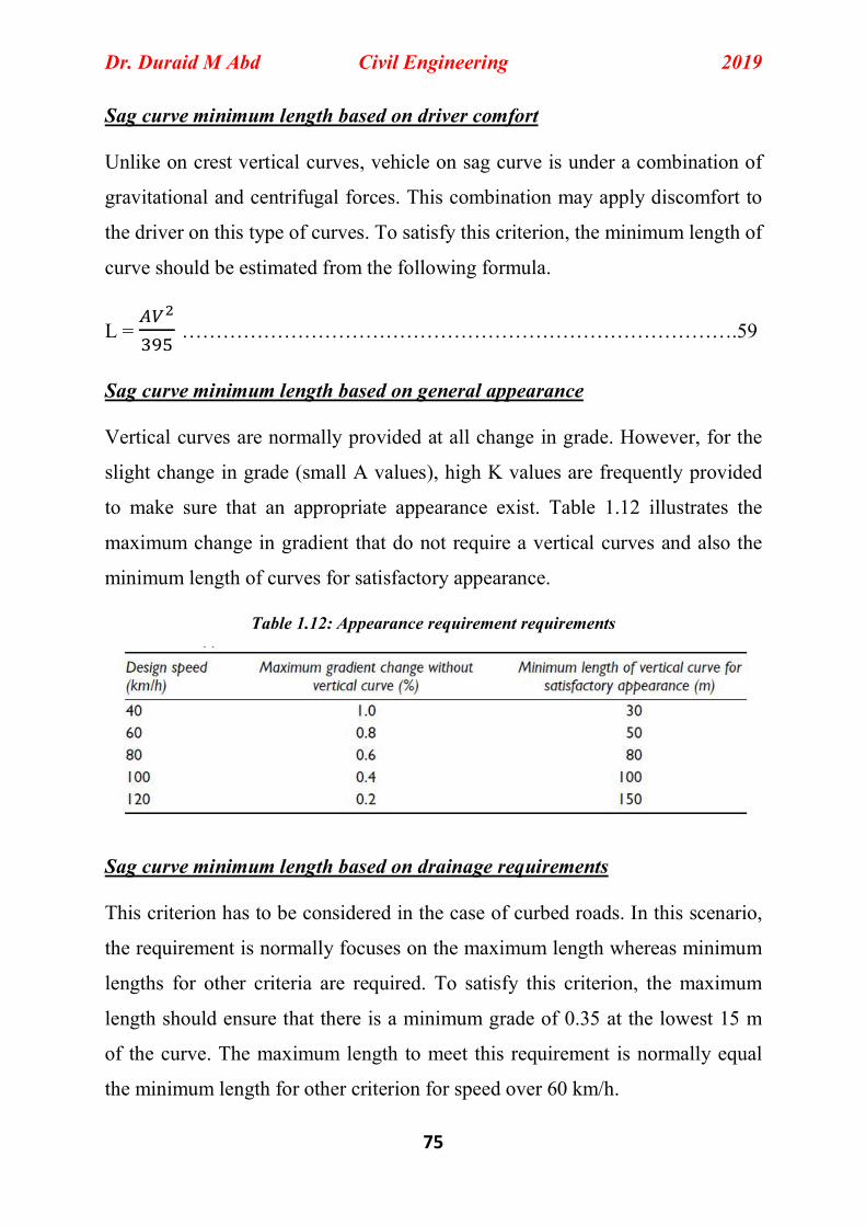
Sag curve minimum length based on general appearance
Vertical curves are normally provided at all change in grade. However, for the
slight change in grade (small A values), high K values are frequently provided
to make sure that an appropriate appearance exist. Table 1.12 illustrates the
maximum change in gradient that do not require a vertical curves and also the
minimum length of curves for satisfactory appearance.
Table 1.12: Appearance requirement requirements
Sag curve minimum length based on drainage requirements This criterion has to be considered in the case of curbed roads. In this scenario,
the requirement is normally focuses on the maximum length whereas minimum
lengths for other criteria are required. To satisfy this criterion, the maximum
length should ensure that there is a minimum grade of 0.35 at the lowest 15 m
of the curve. The maximum length to meet this requirement is normally equal
the minimum length for other criterion for speed over 60 km/h.