first book of radio and electronics
TRANSCRIPT

Science
How does a telephone work? What causes the image you see when you watch television? Who invented the radio and how are its signals sent? If you would like to know about all of these things and more, here is a book that is fundamental, but not too technical, that removes much of the mystery. There are also detailed plans for many projects—among them simple radio receivers, micro¬ phones, amplifiers—and information on how to send and receive radio telegraph signals. All of the projects can be done in a home workshop and are presented in a lucid, interesting way for the young scientist.
First published in 1954 and now available in an up¬ dated edition, Mr. Morgan’s First Book of Radio and Electronics is a classic in its field.
“Recommended especially for those...who like to build this kind of apparatus.”—School Library Journal
“This is a fine book for a (young person) whose study desk is normally covered with a soldering iron, a hacksaw, dry cells, and electronic spare parts.”—The New York Times
Alfred Morgan was born in Brooklyn, New York, and began writing while in high school. After attending M.I.T., he began a radio manufacturing company and continued to write in his spare time. He is the author of many out¬ standing books, both for adults and young readers.
Published by Charles Scribner’s Sons, New York
ISBN 0-684-14756

Other Scribner Library Books by ALFRED MORGAN
A First Chemistry Book for Boys and Girls
Adventures in Electrochemistry

The First Book of
RADIO and ELECTRONICS

by ALFRED MORGAN
THE FIRST BOOK OF
RADIO
ELECTRONICS ILLUSTRATED BY THE AUTHOR AND WALT REED
CHARLES SCRIBNER S SONS NEW YORK

V
Copyright © 1977 Ruth S. Morgan
This is an updated edition of an earlier version of this title, copyright 1954 © Alfred Morgan.
Library of Congress Cataloging in Publication Data
Morgan, Alfred Powell, 1889-1972. First book of radio and electronics. Published in 1954 under title: The
or radio and electronics. Bibliography: p. Includes index.
boy’s first book
SUMMARY: Facts about electricity, radio waves, elec¬ trons and electrcJnics with directions for building radio !«■"» ar\d amplifiers and information on sending and receiving radio and telegraph signals.
1. Radio-Juvenile literature. 2. Electronics-
{"Wssr-n “«£***'2
All rights reserved. No part of this book may be reproduced in any form without the
permission of Charles Scribner’s Sons.
1 3 5 7 9 11 13 15 17 19 C/P 20 18 16 14 12 10 8 6 4 2
Printed in the United States of America
CONTENTS
1 The First Wireless Telegraph and the
First Wireless Telephone 1
2 A Few Facts About Electricity 20
3 About Radio Waves 27
4 Electrons and Electronics 37
5 Radio Tubes—Feedback and Regeneration 89
6 Things You Should Know About the
Parts and Materials Used to Build Radio and Electronics Apparatus 106
7 Crystal Detectors 118
8 Simple, Practical Radio Receivers and How to Build Them 126
9 How to Build a One-Tube Regenerative Receiver 160
10 You Can Build an Amplifier 186
11 The Antenna and Ground for Your Homemade Radio Receiver—How to Solder 206
12 Learning to Send and Receive Radio Telegraph Signals 216
REFERENCE BOOKS 225
INDEX 227

The Boys’ First Book of
RADIO and ELECTRONICS

Chapter One
THE FIRST WIRELESS TELEGRAPH and
THE FIRST WIRELESS TELEPHONE
On March 3,1899, the lightship East Goodwin was at anchor
at her post off the coast of South Foreland, Great Britain. The
beacon light at her masthead which sent its warning beam out
into the night as a guide to passing ships was dimmed by a
heavy fog which hung over the sea. The fog-horn, aboard the
East Goodwin was moaning its caution into the mist and rain
at regular intervals. Between each warning wail there was only
the sound of water slapping against the sides of the lightship.
All else was ominously quiet. Both sound and vision were
deadened by the vapor-laden air.
Suddenly there came a shout from the lightship and follow¬
ing it a shout from elsewhere in the fog. A black hull loomed
out of the darkness and towered over the lightship. There was
a crash and more shouting. The East Goodwin had been struck
by a steamer off its course and the lightship was sinking. Help
must come quickly to be in time. Then began a tiny snapping
and crackling sound. It was hardly more than a faint sputtering
but it was the East Goodwins cry of distress—her appeal for
help. This call from far out on the sea was heard ashore. Life
boats put out to the rescue, and the members of the lightship’s
crew who would have been doomed to die in another age were
soon brought safely back to land.
2 THE BOYS’ FIRST BOOK OF RADIO AND ELECTRONICS
On that day for the first time so far as is known, wireless
telegraphy saved lives in a marine disaster. The faint sputtering
sounds aboard the East Goodwin were made by Marconi’s new
wireless telegraph transmitter. The wireless telegraph had sent
its call for help within a few minutes after the crash occurred
and its message had brought the rescuers. Since then many
ships battered by the wind and waves, disabled and sinking or
afire, have sent their calls for help out into space and aid has
arrived in time. Thousands of people have been saved from a
watery grave by the voice which wireless telegraphy gave to snips clt S6E,
The first wireless telegraph equipment aboard an Atlantic
liner was installed (in 1900) on the Norddeutscher-Lloyd
Steamship Company’s Kaiser Wilhelm der Grosse. A year previ¬
ously (1899) naval vessels were first provided with the wireless
telegraph when the Marconi system was installed on three
British battleships which were then dispatched to the scene of
the Boer War and to the Sandwich Islands. Until 1899, when
a vessel left port nothing was heard from her until she reached
her destination, unless she was sighted by other passing ships
and reported by them when they reached port. There was no
way of communicating between the shore and a vessel out of
sight of land. But after wireless telegraphy was invented, mes¬
sages could be sent through space for hundreds of miles. Now
all vessels of any size carry “radio.” In America the term “radio”
has replaced the old term “wireless.” All passenger vessels are
required by law to carry radio equipment. Many ships are
provided with radio telephones which make it possible for any
of the passengers and crew members aboard to be connected
with any of the millions of telephones belonging to the Bell ~
Telephone system even though the ship is in the middle of an ocean.
Radio broadcasting, telephony across oceans, television,
radar and a multitude of other electronic marvels had their
begmnings in the crude apparatus of the first wireless telegraph.
the first wireless telegraph and telephone 3
The whole history of their development would fill several large
volumes. But it is an interesting story even when told very
briefly. For a beginning, we first look in upon a city in Germany.
THE DISCOVERY OF ELECTRIC WAVES-
HEINRICH RUDOLPH HERTZ
The German Empire was not ten years old when there was
born in the city of Hamburg, Germany, a lusty red-faced baby.
He was named Heinrich Rudolph Hertz.* Young Hertz grew to
early manhood unnoticed and not in any way exceptional. Like
many boys he had ambition to be a civil engineer, so at the age
of twenty he went to a school in
Munich to study for an engineering
career. But in a short time all inten¬
tions to become an engineer left
him. He wanted to study mathe¬
matics and physical science instead.
He changed his plans and 1878
found young Hertz in Berlin en¬
rolled as a student under two of
the world’s greatest scientists, von
Helmholtz and Kirchhoff.
Seven years later he was ap¬
pointed Professor of Physics at the
Technical High School at Karls¬
ruhe. Here in his Karlsruhe labora¬
tory Hertz went to work on a scien¬
tific problem which had first come
to his attention six years before
while he was still a pupil. The prob¬
lem he undertook was to demon¬
strate the theories of a Scotch physicist, James Clerk Maxwell.
The mathematical calculations of this talented Scotsman iden-
* born: February 22, 1857, Hamburg, Germany, died: January 1, 1894, Bonn, Germany.
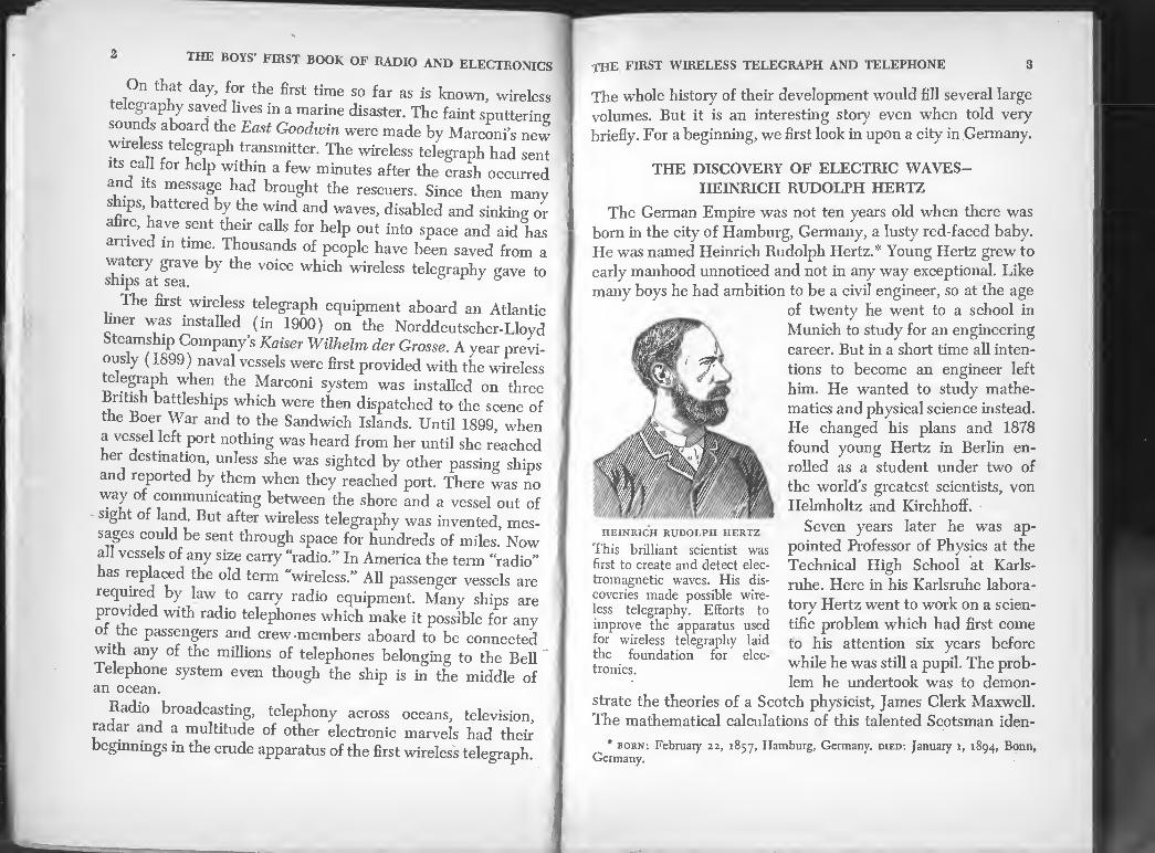
HEINRICH RUDOLPH HERTZ
This brilliant scientist was first to create and detect elec¬ tromagnetic waves. His dis¬ coveries made possible wire¬ less telegraphy. Efforts to improve the apparatus used for wireless telegraphy laid the foundation for elec¬ tronics.

4 THE BOTS- FIRST BOOK OF BADJO *ND ELECTRONICS
and *■-
neitheThf Z Z ly“e hTbeTutf”' “°n paper’" bu‘ demonstrations Noonelmp r n ,1,e to prove them by one knew how to bnHH „ T *° Create *** waves. No these theories. “P apparatus which would prove
and the Emperor 7w,T impure ”exl to B™ardt emperor, solemnly announced that he wnnlrl u
Zi ss* 7 a;T““ “ how it had been fc^mphleT *fa‘* a”d toU
He found a wav to mef ■" aWS “ tbose of J,ght waves,
measurements hT 7l<XZb I' and <mm «“*
the same as light-186,000 milesT se'e^d a"d f°“"d “ *° be
lators°”an“"resi,nators 77 ,7*™“”* with Hertz “oscfl- devised was callJ tv. „ he aPParatus which Hertz had
eaeht,Xthead rLhXat: aT^bah 7° T'/'^ Z?lr£uced S.efor7ofsp7inLeh taCrOSS the,SpaCe be,We“ *hagbit
* SEftS- plates.
THE HERTZ APPARATUS
FOR CREATING AND DETECTING ELECTRIC WAVES
This is the apparatus that Hertz set up to prove Maxwell's theory that light and electrical energy are waves of some sort. Pressing the key or switch connected the induction coil to a battery and caused electric sparks to jump across the spark gap on the coil. Hertz called this part of his apparatus the oscillator. When sparks jumped across the oscillator spark gap, electric waves moved out into space and generated tiny sparks in the gap in a resonator near by. The Hertz resonator consisted of two metal balls attached to the end of a copper wire bent in a circle until the balls almost touched each other.
The resonator consisted of two brass balls fitted to the ends
of a copper wire which was bent in a circle until the balls
almost touched one another. When this ring was held near the
oscillator and sparks from the induction coil leaped across the
space between the balls connected to the metal plates the elec¬
tric waves thus created caused tiny sparks to appear between
the balls on the ring. By such means Hertz produced waves

6 THE BOYS’ FIRST BOOK OF RADIO AND ELECTRONICS
aZnttaeter waves wa” " ^ngth- TodV we method produce d ** ”” md « * “°re <***
sit in your home and listen to or CdTa foX^T' ^
orchestra, your entertainment conies to ytm ^a^Hertzian^vaves!
GUGLIELMO MARCONI AND THE
INVENTION OF WIRELESS TELEGRAPHY
18m!T 3d70fFbl0Od P°iSOning °n New Year’s Day,
of'I20th^Hr?n°f ^ Same year’ an imaginative young man
Italia’ AlpJwhileioking
great
wi* elec,no waves. Vonng Mar^th^S^ I
erest and an idea dawned in his mind.* Why couldn’t Tele
S the^ ,be T* thr0“Sh *• - whhont wte With the Hertz .apparatus? Enthusiastic over this idea he n
“rP“ “ • *—
into JTom ™sefofeIsyh?h«eIS T°Pt“‘ 'h<i ““ i.0 _i t. y* was no Quick answer at hand. It was not possible to build wireless telegraph Su
menis as soon as Hertz showed the world how toproduce and
detect electric waves. Otherwise some one would have pro
. ® 3 Practlcal system of wireless telegraphy before Marconi.
that amateur w'rdess^ocper^menterr^aafuired ^the^a"^3^ “ 7^Ch the same waY he read about them. After he had beeomp f me knowledge in later years.
h' Ss-^s fsnsss „„ of Nan?SK;nT cU.'intp^L^
the FIRST WIRELESS TELEGRAPH AND TELEPHONE 7
william marconi—21 year old inventor— AND HIS APPARATUS FOR SIGNALLING WITHOUT WIRES
July 17, 1897 the Scientific American Supplement (No. 1124) printed a discourse entitled “Signalling Through Space Without Wires” delivered before the Royal Institution June 4, 1897 by Sir William Preece. Over 50 years ago the author of this book clipped the article out and pasted it in his scrap book. The article was illustrated by engravings originally pub¬ lished in L Illustration and London Engineer. The illustration above was sketched from one of these engravings by permission of the scientific
American. It apparently shows the wireless telegraph apparatus which Marconi took to England with him. This apparatus could do little more than prove that wireless telegraphy was possible. The Righi oscillator is at Marconi’s left. Sir William Preece described the Righi oscillator as “two spheres of solid brass, 4 in. in diameter—fixed in an oil-tight case of insulating material, so that a hemisphere of each is exposed, the other hemisphere being immersed in a bath of vaseline oil.” The Righi oscillator gave better results than the simpler Hertz Oscillator. The receiver is at Marconi’s right. A telegraph sounder is mounted on top of the cabinet.
A Hertz resonator would not detect waves more than a few feet
distant from the wave-producing Hertz oscillator. A practical
wireless telegraph could not be made without first learning how
to produce stronger electric waves than those Hertz had pro¬
duced. A sensitive instrument to replace the Hertz resonator—

8 THE BOYS’ FIRST BOOK OF RADIO AND ELECTRONICS
an instrument which would detect the electric waves at a great
stance from the transmitter-a distance which could be meas¬ ured in miles—was necessary.
An important step toward solving one of these problems had
been made by the tune young Marconi became interested.
Edouard Branly of Paris had made the first step when he
demonstrated that electric waves would affect powdered
metals. An electric current does not flow easily through a
loosely packed powdered metal. Loose metal powder offers
great resistance to the current. Branly showed that an electric
current would pass through metal powder more easily after the
powder had been struck by an electric wave. The wave caused
the particles of powder to cling together or cohere and lowered tneir resistance to an electric current.
Branly also found that a mechanical shock, such as tapping
the tube in which the powder was contained, caused the con¬
ductivity of the powder to disappear and restored its resistance
? Currfn[‘ This knowIedge enabled him to devise the which he exhibited before the French Academy in
ioyi, thereby winning membership in that body.
Branly s coherer consisted of a glass tube filled with loose
iron filings connected to a galvanometer and battery. A galva¬
nometer is an instrument for measuring small electric currents
Electric waves produced by a Hertz oscillator 25 yards distant
caused the iron filings to cohere (thus the name coherer) and
the galvanometer to indicate an increase in the current flowing
through the filings. A tapper arrangement, a tiny hammer like
that on an electric bell, tapped the tube and shook the filings so that they were restored to a loose state.
We are accustomed to read and hear of poor boys who by
hard work and ability became famous and often became rich.
The life story of Guglielmo Marconi is not the usual rags-to- I
riches tale. He came from a family with adequate means. He I
had culture, education and some money but not a fortune. His
father, Giuseppe Marconi, was an Italian banker. His mother
9 THE first wireless telegraph and telephone
(nee Ann Jameson) was the youngest daughter of Andrew
Jameson of the well-known whiskey distillers of Dublin.
Guglielmo (the Italian for William) was the second son; he
had an older brother named Alfonso.
The idea that Hertzian waves might make it possible to
transmit telegraphic signals over distances great enough to be
of commercial value fascinated Guglielmo Marconi. He started
his experiments at his father’s country home, the Villa Griff one,
at Pontecchio near Bologna. He brought together an induc¬
tion coil, telegraph key, batteries, Branly coherer and Hertz
resonator.
The first tests were carried out with an ordinary Hertz oscil¬
lator and a Branly coherer as detector. The Branly coherer
was soon found to be far too erratic and unreliable for practical
work and was discarded. After many experiments, a coherer
having the same principle as Branly’s but of Marconi’s own
improved design proved to be remarkably sensitive and reliable.
It consisted of nickel and silver filings placed in a small gap
between two silver plugs in a glass tube. This improved coherer
made it possible to send wireless telegraph messages through
space for distances of almost a mile. A telegraph key placed in
the battery circuit at the transmitter made it possible to trans¬
mit waves for long or short periods corresponding to the dots
and dashes of the telegraph code.
In August, 1895, Marconi discovered that he could greatly
increase the distance between his transmitter and receiver by
connecting an elevated wire or antenna and the earth to both
the transmitting and the receiving apparatus. The coherer was
placed in a circuit containing a sensitive relay which operated
a “tapper” to shake the coherer and also operated a recording
instrument. This arrangement recorded on a paper tape the
telegraph signals made by pressing the key at the distant
transmitter.
In July, 1896, Marconi took a step which had an immense
influence on his future. He discontinued his experiments in

10 THE BOYS’ FIRST BOOK OF RADIO AND ELECTRONICS
Office a„d oneTie %£ £*
The young Mental succeeded in convincing Preece that hk
■deas for a system of wireless telegraphy were macted^
^^ ^-SaUmy&“La
relay
MARCONI S COHERER AND ITS CIRCUIT
toraT„?s3rogte'S wa,s **??practicaI de,“- and an internal diameter of r millimptery m i°ng, ^about 1^ inches) or plugs which fitted the tube tightlv T<TtheP ^ tW° Silver electrodes num wires sealed through the closed InL fhfu P,Uf wf£f attachcd plati- the plugs were pdishedtSl^S^J^^ of the plugs was filled with nickel and siW fir S fpart* T e sPace between and 5 per cent silver filings! All the aI T (95 pCr Cent nickel filings and it was sealed^ ' A” the air W3S then PumPed out of the tube
the receiver. When radio waves na«ed n sketch shows the circuit of
cohered and current from a batterv ('B-’ iF flnS' cohe,rer> *be filings relay. The relay closed the tapper circuit and r d wr0Ugh ,the sensitive
operated the tapper and shook the filings LartT thTthe for the next signal. S p rt so tllat Iney were ready
the first wireless telegraph AND TELEPHONE 11
The first inkling that science might soon bestow such a
marvel as a practical system of signalling through space for
long distances without wires came to the world in general in
June, 1897. On Friday evening, June 4,1897, Sir William Preece
told a meeting of the Royal Institution about young Marconi’s
successful experiments. Today when radio encircles the globe,
when a “ham” in midwest U. S. A. can go into his “shack” and
talk to another “ham” in Australia, it is interesting to read what
Sir William had to say about the infant wireless at a time before
its christening, when lacking a name, it was called “signalling
through space without wires.”
Here are some of Preece’s words:
The distance to which signals have been sent is remarkable.
On Salisbury Plain, Mr. Marconi covered a distance of four
miles. In Bristol Channel this has been extended to over eight
miles and we have by no means reached the limit.”
In 1898, Marconi’s new wireless telegraph was installed
aboard the royal yacht Osborne. This enabled Queen Victoria
to maintain constant communication with the then Prince of
Wales (King Edward VII) who was convalescing from an ill¬
ness aboard the yacht. The first commercial use of wireless
occurred in this same year when Marconi sent a report of the
Kingston Yacht Races to the Dublin Express from aboard the
tug Flying Huntress in the Irish Sea. Wireless communication
was established across the English Channel between France and England for the first time in March, 1899.
The now 24-year-old Marconi proved to be a young man of
great courage and imagination. In his mind he foresaw tele¬
grams flashing over the broad expanse of the Atlantic Ocean.
He determined to make this vision a reality. A high-power
transmitting station was built at Poldhu on the coast of Corn¬
wall, England. Everything was on a much larger scale than
Marconi had attempted previously. Professor J. A. Fleming was
entrusted with designing and arranging the apparatus for gen¬
erating the powerful alternating current which was to be em-
12 THE BOYS' FIRST BOOK OF RADIO AND ELECTRONICS
ployed at the transmitter. In addition to the work of ProWn
emmg, valuable technical assistance was given bv R n" Vyvyan and W. S. Entwhistle. S 7 K' N‘
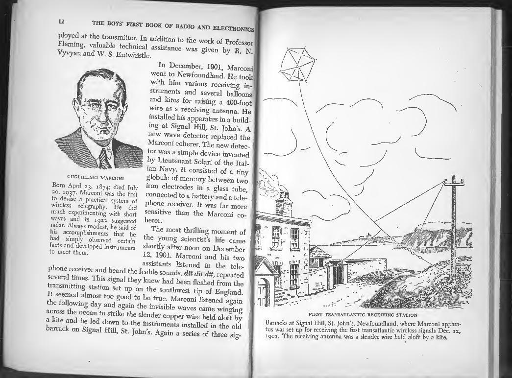
In December, 1901, Marconi
went to Newfoundland. He took
with him various receiving in¬
struments and several balloons
and kites for raising a 400-foot
wire as a receiving antenna. He
installed his apparatus in a build¬
ing at Signal Hill, St. John’s. A
new wave detector replaced the
Marconi coherer. The new detec¬
tor was a simple device invented
by Lieutenant Solari of the Ital¬
ian Navy. It consisted of a tiny
globule of mercury between two
iron electrodes in a glass tube,
connected to a battery and a tele¬
phone receiver. It was far more
sensitive than the Marconi co¬ herer.
The most thrilling moment of
the young scientists life came
shortly after noon on December
12, 1901. Marconi and his two
i . , assistants listened in the tolo
siTrairttaerTh 1 ^ ^ Sounds■ «* <* <St repeated several times. This signal they knew had been flashed from the 1
2“"*. Stati™ - "P °n the southwest tip of Enlud It seemed ahnost too good to be true. Marconi listened arato I the following day and again the invisible waves came winfinv
“drw°dstrik: Slender “W- wire S
barrack oaSiim St toStalled£ ta 1,16 oId gn ll, bt. Johns. Agam a senes of three sig-
GUGLIELMO MARCONI
Born April 23, 1874; died July 2°, 1937. Marconi was the first to devise a practical system of wireless telegraphy. He did much experimenting with short waves and in 1922 suggested radar. Always modest, he said of his accomplishments that he had simply observed certain tacts and developed instruments to meet them.
FIRST TRANSATLANTIC RECEIVING STATION
Barracks at Signal Hill, St. John’s, Newfoundland, where Marconi appara¬ tus was set up for receiving the first transatlantic wireless signals Dec. 12, 1901. The receiving antenna was a slender wire held aloft by a kite.

14 THE BOYS’ FIRST BOOK OF RADIO AND ELECTRONICS
nificant sounds corresponding to the letter S in the telegraph
alphabet confirmed the fact that the trackless Atlantic had been
spanned by Hertz’s waves and Marconi’s own ingenuity and daring. His dream had been realized.
Little did this quiet, modest, young inventor-or any one at
ANTENNA
ANTENNA
SPARK GAP
'"iprovCd!
batt£i
BATTERV
INDUCTION COIL
TELEGRAPH KEY
AN AMATEUR TRANSMITTER OF SEVENTY-
Newspaper accounts about Marconi’s experiments in England stimulated amateur scientists to build wireless telegraph instruments. In America just after the turn of the century, boys began to tinker with wireless telegraphy. Many of them were cultivating a hobby which later became their vocation. The first amateur transmitters and receivers were some¬ what similar to Marconi’s early apparatus and were capable only of sending messages across a large auditorium or from one room to another in the same house. The amateur transmitter of those days consisted of a spark coil htted with a spark gap and connected to a key and battery.
Tuning Coil
Microphonic Detector
tenna wire; 6, wire.
the first wireless telegraph and telephone 15
rt.-t time-think that the same Cugliehno Marconi would be Sing in a comfortable room in London thirty years later to a
fv and in a quiet, conversational tone speak words that tould be heard by millions of persons all over the_worR Ye
December 11, 1931, Marconi’s own voice and words tribute to him from fifteen nations encircled the earth via radio¬
phone
THE FIRST AMATEUR DETECTORS
The coherer of the earl, replaced by more sensitive of tw0 carbon blocks, a steel sewing needle resting on th*^ SoZ receive,. Micro-
d— ,nd then
\SndSm^
sssatASwa * -

16 THE BOYS’ FIRST BOOK OF RADIO AND ELECTRONICS^
versaiy of “■*
Radio resulted
from THE WORK OF MANY MEN
the d^cwerTeTotHerteBra^I10’ ^ CTbining and improving
«cal wireless *£££&£ ST *" ^ ^ is by no means the work of a sin trip • a °m Present daY radio During the past six deradoc tL ^ mi? °r even a ^ew minds, patents have been granted to °“san s ra<U° and electronics
tors. The pioneer ££££* paratively crude tools Tn *. • a. , Wlt“ simple, com-
Which others soolZlroyTZ ^ S* “* Series
have become moreZinfa 2TJthf”' 'Z ^'ons experts in various fields*^ C" re<!ulre *he assistance of
boZfoZrt“yynZpZlrSvh fa ti0,“d **»*% more than two or three of thP p’ t US book to recount
an aptitude for science and aro ’ °f y°jUng PeoPle wh« have
first radiotelephone, ^
back oSote’ SomeofatiiSt °fjtereSting books a“he
public hbraries Can^^^ ^
REGINALD A. FESSENDEN
ND THE FIRST RADIO BROADCAST
jackpot^n a^di^qutr6 ^ feW,P®°pIe who couId win the
be “Who ^ty^d toqU6Sti0n haPPened *> thing he accomplished?” 060 Can you teI1 me some-
rf ° pi°neer md *"-*»■ tt* of Hertzian waves^SteTT ^ ^ * —» phone. U. S Patent No 70R 7/)?r firSt PractlcaI wireless tele¬
phone was granted **- tele-
17 THE FIRST WIRELESS TELEGRAPH AND TELEPHONE
Fessenden was bom and educated in Canada. His first job
was that of principal of the Whitney Institute in Bermuda. But
his interest in electricity was so great that he decided to give
up teaching and go to New York in hopes of finding employ¬
ment with Thomas A. Edison. He started as a tester with the
Edison Machine Works and finally became one of Edison’s
assistants at the Llewellyn Park Laboratory. He acquired the
title of Chief Chemist at the Laboratory. He left Edison’s
employ in 1889 to resume teaching again. Three years later he
had become professor of electrical engineering at Purdue Uni¬
versity. From there he went in turn to similar posts at the
University of Pennsylvania and to Western University of Penn¬
sylvania. At both of these institutions Fessenden lectured on
Hertzian waves and carried out numerous experiments with
them. These facts about Fessenden’s early career may be uninter¬
esting to many readers of this book. They are recited here to
show that youth need not be a handicap in scientific accom¬
plishment. They add another name to the long list of very
young men who achieved great things in science at an early
age. Fessenden was 22 years of age when he was Edison’s “Chief
Chemist.” It has been mentioned that Marconi was but 21
when he took his new wireless telegraph to England. Edwin H.
Armstrong, about whom we will read more later, was a college
student when he developed a radio circuit and a new principle
in the use of electron tubes which were a revolutionary advance
in radio. There is not space in this volume to cite the accom¬
plishments of all the young men who contributed to the science
of radio. , „ It is sometimes said that “everything has been discovered,
and that young men today do not have much chance to do
original things in science. This is not true. A good share of the
new discoveries of the future will be made by scientific pioneers
who have not long been old enough to vote. Now back to Fessenden. In December, 1899, a maker of
scientific instruments in Washington, D. C., constructed a ro-

THE BOYS’ FIRST BOOK OF RADIO AND ELECTRONICS
tating commutator for Fessenden-probably from the joint
designs of himself and Fessenden. The purpose of this devLe
was to create an alternating current whose fluctuations would
occur so rapidly as to be above the range of the human ear It
was planned to send this rapidly alternating current into an
antenna and thereby produce Hertzian waves which would carry music and the human voice. d
Fessenden did not test his invention until October, 1900 But
'rofessor
. th f t tlnle hy Hertzian waves. In 1902 the Na- honal Electric Signalling Company was organized to develop
shifted “the CS a"d .taventi0ns' His activities were then slutted to the Company s new station at Brant Rock Massa
chnsetts. On Christmas Eve. MO* radio operators aboard ships
CATCH WIRE
dry battery
'«* PMinac rru’XM
EARLY AMATEUR RECEIVER
'■•vnc.uc.rr AINU DEC
r -
An Amateur Wireless Telegraph Receiver .
of 1905 /
the FIRST WIRELESS TELEGRAPH AND TELEPHONE 19
along the coast, long accustomed to hear only the dots and
dashes of the telegraph code and the clicks and crashes of static
in their headphones, were startled to hear voices and music.
Ships reported reception as far down the coast as Virginia. This,
the first broadcast, had been transmitted by the Brant Rock
station. Later the voices were reported heard in New York,
Washington, D. C., and New Orleans. More than 500 inventions were attributed to Reginald Fes¬
senden during the 30 years he was actively engaged in develop¬
ing his imaginative ideas in the fields of Hertzian waves, sound
and light. Marconi’s feat of sending wireless telegraph signals
across the Atlantic ocean remained unrivaled until 1906 when
Fessenden equalled it. Those who became amateur radio oper¬
ators or “hams” during the first decade of this century will
remember the electrolytic detector and the rotary spark gap.
They "Were both Fessenden inventions.

21
Chapter Two
A FEW FACTS ABOUT ELECTRICITY
tPU Chapter and turn Mediately to the pages winch explain how to build radio receivers. Skip it if you wish it is better not to do so. Here is the reason:
No doubt you will agree that in order to read or spell it is
necessary to know the letters of the alphabet. It is equally true
that you must know the “ABCs” of electricity before you can -
m e lgently build radio and electronic apparatus. There are
The ABC’s'of31 and eIectronics.
Sc plcip.1 ^ are a fW fundame”W
ElecWcity Is a Fom. of Energy. The Srst fact to learn about
"° °"e_n0t eVen the abIest dentists—knows
fa ral of rt T? h' ScirnHstS knOW onIy *hat dectrieity exirtsintW Severfhrms of md that it apparently
*e toIm of tmy Partid“- E^rgy, as a scientist views , the capacity FOE pebforming work. Energy can take dif-
IZI °T .rd - SL FORMS of gy. They are not different energies-they are different
forms of the same thing. Each form of energy cl be converted
t2 21Z ‘de °theAf0nnS- °f ^ Pt-ssTlS p ce in sending and receiving radio messages and tele¬
vision change one form of energy into another foL. AA 20
A FEW facts about electricity
Electrons. Scientists have discovered several kinds of elec¬
trical particles. Some are charged negatively; some show no
charge; others are charged positively. The negatively charged
particles are called electrons. In radio, electrons are of more
interest than the other lands of particles. Some neutral elec¬
trical particles (neutral because they show no charge) are
thought to be combinations of positive and negative particles.
Electric Current. A moving electron is an electric current.
The electric currents used in radio consist of a large number of
moving electrons. The amount of electric current represented
by a single moving electron is so small that it cannot be detected
by the most sensitive measuring instruments. It requires billions
of billions of electrons to produce currents of sufficient strength
to be useful. Approximately 5,240,093,717,045,500,000 electrons
must move through the filament of the common 100-watt, 120-
volt tungsten lamp each second in order to light it to full
brilliance. Immeasurable billions of electrons move through the
electrical wiring in your home to supply illumination for a
single evening. The Terms D. C. and A. C. The letters D. C. are an abbrevi¬
ation for District of Columbia but they are also an abbreviation
for direct current. A current of electricity which always flows
in the same direction is a direct current. The current produced
by a battery is direct current. So is the current from an auto¬
mobile generator. A. C. is the abbreviation for alternating current. An electric
current which constantly and regularly reverses its direction
of flow so that it surges back and forth in a circuit is an alter¬
nating current. The first generating stations produced direct current for light
and power. Alternating current came into use later. Alternating
current can be distributed more efficiently and for greater dis¬
tances that direct current. Consequently the electrical power
which is produced nowadays at large generating stations and
sent over transmission lines is alternating current. The cur-

THE BOYS’ FIRST BOOK OF RADIO AND ELECTRONICS
rent which comes into our homes from a distant generating
stohon to provide power and light is alternating current if usually flows m „„e direction, lhen revmes andSflows
cflfed 60 ref°n 60 “T Per SeCO”d’ For lhat reason « fe called 60 cycle current. One complete flow of current back¬
wards and forwards is called a cycle and the number of cycles
per second is known as the frequency.
High-Preqiiency Alternating Currents. Electric currents
can be made to alternate or reverse their direction of flow fewer
or more than 60 times per second. They can be made to alter-
per'second T 7 & ITT;65 3 SeCOnd t0 miIlions of times per second. Currents which alternate 100,000 times or more
per second are called radio-frequency, high-frequency and
oscillatory currents. The currents used to produce radio
theVmo7 radl°;frAeqUenCy CUrrents' The AM which carry
radio frfnamS nCan br°adcast stati0ns are produced by adio frequency currents ranging from 550 to 1700 kilocycles7
Kilo is a term derived from a Greek word meaning thousand 550 kilocycles are 550,000 cycles. The waves which carry fm
d lrr S1§nals and aIso those used for radar are pro-
aZ d 7 alt7ating CUrrCntS Which reverse their direction of flow mdhons of times per second. They are rated in megacycles.
There is part of another Greek word in this term, namely mesas meaning large. Meg and mega are used in science to JTn
mhxion. A megacycle is 1,000,000 cycles. This bit of infor-
in radio ^ ^ ® ^ *° Understand some of the terms used
Wires, Insulators and Electric Currents. Fortunately, elec-
w~t 7 n0t?0W thr0U§h a11 materials. Otherwise we d not be able to keep electricity under control and lead it
wherever we wish The materials through which electric cur¬
rents flow most easily are called conductors. All conductors do
not carry electricity equally well. Those which conduct poorly
have^sisTANcz to a current and are called partial conductors7
Materials through which electric currents do not flow are called
23 A FEW FACTS ABOUT ELECTRICITY
non-conductors. The non-conductors used to protect the wires
and parts of an electrical circuit so that current will not leak
through them are called insulators. Porcelain, rubber, glass,
mica, waxes and Bakelite are common insulators employed in
the construction of radio and electrical equipment.
The best conductors are metals and water solutions of cer¬
tain chemicals. Copper is an excellent conductor of electricity.
An electric current can flow through copper more easily than
through any other metal except silver. Silver is too expensive
to use for electrical wires except in some special instruments.
Since copper costs less and conducts almost as well as silver,
it is commonly employed in the form of wire to conduct elec¬
tricity from place to place.
Copper wires are often covered with an insulating material
to prevent short-circuits and leakage of current when wires
touch adjacent objects or touch each other. Many materials
are used as insulation on wires, for example, rubber, plastics,
glass fiber, wax, cotton, silk and various chemical coatings.
ELECTRICAL MEASUREMENTS
Almost everything must be measured at some time or other.
The measurement may be in seconds, days, weeks, quarts,
gallons, pounds, tons, inches, feet or miles by some special
system. Measuring is simply a means of comparison. Although
electricity cannot be seen, heard or touched it can be measured
by comparison to a standard for electricity. So also can the
circuits and conductors which provide a path for electricity
and harness it for some useful purpose. You will find the words
volt and ampere used in this book. They are measuring units
for electric current.
The Volt. Voltage is often called electrical pressure. Just
as air or water flowing through a pipe exerts pressure so does
an electric current exert pressure when it flows through a wire.
Electrical pressure cannot be measured in pounds but can be
measured by a unit called a volt. The abbreviation for volt is V.

K u* KADIO and electronics
h and not supplying current, has
e of 1.5 volts. When two dry cells
iltage is combined and amounts
consists of 30 cells connected in
requires voltage in order to overcome
it meets in conductors. A single 1.5-volt
J enough voltage to overcome the resist- 1
~ y°u Place dry fingers on the termi-
youprobablywill not feel any shock.
" " , - -----y to overcome the I give a^shock unless the fingers are calloused. I
- "0 times as much voltage as a single
as much current through !
'ing current delivered
ally about 120 volts, i
pressure as the 1.5-volt i J 80 times as much cur- ■
necessary to have a measuring unit
an electric current. It is called the
amperes means a certain definite amount of
i a circuit in one second just as 2 gal-
’’ J rate at which water may be
-; lamp
ampere in order to light to full
1H4G radio tube used in one of
--; requires much less cur-
an electrical pressure or voltag
are connected in series the v(
to 3 volts. A 45-volt B battery
series. An electric current
the resistance which i' dry cell does not have <
ance of the human skin. If you pi
nals of a 1.5-volt dry cell
There is enough voltage in a 45-volt B batter
skin resistance and _1 '
A 45-volt B battery has 30 L
1.5-volt dry cell and will force 30 times i_~.
a circuit. The voltage of the house light]
to residences by public utilities is usu;
120 volts is 80 times as much electrical r
pressure of a single dry cell and will force
rent through a circuit.
The Ampere. It is also
for the volume of flow of
AMPERE. Two ■-
electricity flowing through
Ions per second indicates the
flowtag through a pipe A 100-watt, 120-volt incandescent requires slightly less than one
brilliancy. The filament of the
the receivers described in this book :
rent, namely 0.06 amperes.
HOW TO UNDERSTAND THE W
Any of the condensers, resistors, coil
which are part of the radio apparatus
can be illustrated by a simple drawing
experimenters, engineers and mechanics
make wiring diagrams or “hookups” whic
A few facts about electricity 25
than words can how to build or connect any sort of radio or
electronic apparatus. Three kinds of diagrams are used to illus¬
trate radio circuits: pictorial diagrams, block diagrams and
schematic diagrams. All three will be found in this book. Pic-
j [
CRYSTAL DETECTOR
CONNECTED WIRES
Hh FIXED
CONDENSER
T 0 ANTENNA GROUND TELEPHONES
"0 WIRES CROSSING NOT CONNECTED
BINDING POSTS
SPEAKER
H(- i T
- -L
VARIABLE CONDENSER
SINGLE CELL BATTERY
1.0-0-00 J UImJ ^/WVW^- -MAaW- INDUCTANCE VARIABLE RESISTANCE
INDUCTANCE VARIABLE
RESISTANCE
AIR-CORE IRON-CORE TRANSFORMER TRANSFORMER
0^*6 SWITCH
*VF- ELECTROLYTIC
CONDENSER
IF =D=
CRYSTAL PHONO PICKUP
POWER PLUG
POWER OUTLET
Q 0 “0 FILAMENT CATHODE GRID
PRONG JE BASE
6 PLATE
THE SYMBOLS USED IN RADIO CIRCUIT DIAGRAMS
Symbols are a sort of radio shorthand used to make schematic circuit diagrams. These are standard symbols used in radio books and magazines. Only those symbols used later in this book are shown.

26 THE BOYS’ FIRST BOOK OF RADIO AND ELECTRONICS
torial diagrams are most easily understood by beginners; the
condensers, detectors, transformers and other parts are readily
recognized. The pictorial diagrams will help you to understand
schematic diagrams. Schematic diagrams employ symbols
which are a sort of radio shorthand. For example, instead of
showing a drawing of a variable condenser a symbol like this
—1(— is used. Notice that one line in the symbol is straight
and that the other is a curved arrow. The fixed line represents
the immovable plates or stator of the condenser, the curved
arrow is a symbol for the movable plates or rotor.
A schematic circuit diagram of a receiver which shows the
sizes of the condensers, resistors, etc., is like a plan for a house
or machine. It shows how all the parts are assembled and any¬
one familiar with radio construction can assemble the receiver
without any information other than the diagram.
When you become familiar with the symbols, you will prefer
schematic diagrams.
VARIABLE CONDENSER
Pictorial Diagram
Schematic Diagram
PICTORIAL AND SCHEMATIC DIAGRAMS COMPARED
Here are two methods of illustrating the same thing. Both sketches show a variable condenser connected to a tuning coil called a variable induct¬ ance. The left hand sketch is a pictorial diagram. A schematic diagram is at the right. Not everyone can draw pictorial diagrams but it is not diffi¬ cult to make schematic diagrams. Radio technicians, engineers and experienced amateurs prefer schematic diagrams. Pictorial diagrams are more easily understood by beginners. Since this book is for beginners, both types of diagrams are used.
Chapter Three
ABOUT RADIO WAVES
If you stand at the edge of a pond and strike the surface of
the water with a stick. or small waves wffls^ead out
from the spot on the surface where the stick struck. T
waves wi/spread in circles until they reach the opposite shore
if it is not far. It would be possible to arrange a code or signals
fo tha”by counting or timing the waves they would carry a
message to another person standing on the opposite shore °*
the pond. For example, two groups of waves, “"efollowmg
other after a short interval could mean no. In the same w y,
three groups of waves spaced a few seconds apart could
'"This Staple arrangement whereby groups of waves carry a
message illustrates the principle of radio communication More
than 75 years have passed since the first wireless telegraph mes¬
sage wal sent and received but present day -dio —ca¬
tion uses the same basic principles empteyed before th,^, of the century. Broadcasting, television, radar, ra°'°
telegraphy, and radiotelephony consist of cheat
D“i”jr:' in use is vastly more complicated
and much more efficient than the first radio apparatus but ra
still depends upon the discovery that:
27

28 Tin: BOYS’ FIRST BOOK OF RADIO AND ELECTRONICS
1. When a very rapidly alternating electric current flows
into an antenna wire some of the electrical energy will radiate
out into space in the form of Hertzian waves.
2. When these waves strike another antenna they will create
therein feeble alternating currents similar to those which pro¬
duced the waves.
A radio broadcast receiver changes these feeble currents into
sounds; a television receiver changes them into sounds and
pictures.
Radio apparatus for producing radio waves is sometimes
arranged so that the waves are formed into a beam like the
beam of a searchlight which can be sent in any desired direc¬
tion. The radio waves used for communication between Europe
AN “ELECTROMAGNETIC WAVE PIANO”
Radio waves, light and X-rays are electromagnetic waves. The waves that produce X-rays are very short. The waves which produce light visible to human eyes are longer than X-ray waves but not so long as radio waves. If apparatus having a keyboard like a piano could be arranged so that pressing the keys would produce electromagnetic waves of different lengths, the effect could be:
When the keys at the left, or bass end of the keyboard were pressed, long radio waves would be sent into space. Pressing some of the keys to the right of the bass would produce heat. Pressing the proper key farther to the right would produce a bright red light. Other keys in the same octave would bring forth orange, yellow, green, blue and violet light. Higher up, in the treble, pressing a key would send forth X-rays.
about radio waves
and America and between North and South America are
beamed in this manner. In the early days of wireless, the
antenna was usually arranged so that the waves spread out in
circles with the transmitting antenna as their center.
THE MEANING OF THE WORD RADIO
The fact that electric waves are a form of radiant energy
and radiate from the antenna brought a new word into use.
radio replaced the earlier term “wireless and has been adopted
into our language to mean “the transmission and reception of
signals by means of electric waves without a connecting wire.
HOW ELECTROMAGNETIC WAVES ARE PRODUCED
When Hertz discovered how to produce electric waves, the
waves were named Hertzian waves in his honor. This term is
seldom used nowadays. The names in popular use are radio
waves” and “air waves.” The term, “air waves,” is often used
by newspapers and radio announcers, but is a complete mis¬
nomer. Hertzian waves are not “air waves.” They pass through
air in moving to or from a radio station but the air is not the
medium which makes their passage possible. The effect of the
air on Hertzian waves is so slight that it can be ignored for
practical purposes. Winds do not disturb the waves. Air which
is ionized (the air molecules bear an electric charge when air
is ionized) has an effect upon the path of radio waves and as
we shall see later aids in long-distance radio communication.
Hertzian waves, or radio waves as they will be referred to
in the remainder of this book, are electromagnetic waves.
They have both an electrical and a magnetic character. Radio,
light, heat, x-rays and many other effects are due to electro¬
magnetic waves. ■ The apparatus for creating radio waves is called the trans¬
mitter; that which detects the waves and renders their mes¬
sages intelligible is the receptor, or as it is popularly called,
30 THE BOYS’ FIRST BOOK OF RADIO A AND ELECTRONICS > C > c
the receiver. Radio waves are
created by sending rapidly dp
alternating currents into an i
insulated wire called the an- ffi
tenna. An antenna is used also |1
at the receiver to pick up or ||
intercept the incoming waves. #
In this instance “insulated
wire” does not mean a wire fr
covered with insulation. An- Jr
tennas are usually bare wires,
insulated from the earth, from J *
their supports and from sur- JpV
rounding objects. However, / /l. \\
there is a type of antenna / Jr \\
which is known as a “grounded / | * \\
antenna.” It is insulated in the / |"
usual manner except at a point / | •
where it is purposely con- / | ‘
nected to the earth. An an- j 11 x (( ^
tenna may consist of a single Z' ' |l ' \z^
wire or an elaborate arrange- ' ^ Jr ^
ment of wires. These state- ' §L —-- Z
ments do not apply to the Jr
antennas used for television, Wj
radar and the extremely short w
waves called microwaves.
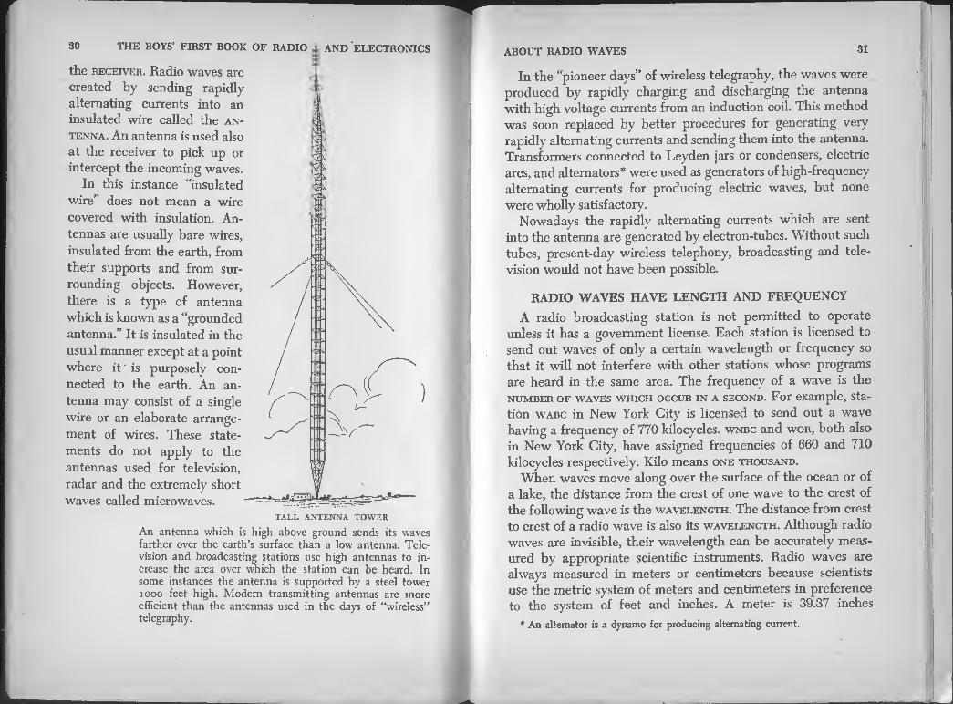
TALL ANTENNA TOWER
An antenna which is high above ground sends its waves farther over the earth’s surface than a low antenna. Tele¬ vision and broadcasting stations use high antennas to in¬ crease the area over which the station can be heard. In some instances the antenna is supported by a steel tower 1000 feet high. Modern transmitting antennas are more efficient than the antennas used in the days of “wireless” telegraphy.
ABOUT RADIO WAVES 31
In the “pioneer days” of wireless telegraphy, the waves were
produced by rapidly charging and discharging the antenna
with high voltage currents from an induction coil. This method
was soon replaced by better procedures for generating very
rapidly alternating currents and sending them into the antenna.
Transformers connected to Leyden jars or condensers, electric
arcs, and alternators* were used as generators of high-frequency
alternating currents for producing electric waves, but none
were wholly satisfactory.
Nowadays the rapidly alternating currents which are sent
into the antenna are generated by electron-tubes. Without such
tubes, present-day wireless telephony, broadcasting and tele¬
vision would not have been possible.
RADIO WAVES HAVE LENGTH AND FREQUENCY
A radio broadcasting station is not permitted to operate
unless it has a government license. Each station is licensed to
send out waves of only a certain wavelength or frequency so
that it will not interfere with other stations whose programs
are heard in the same area. The frequency of a wave is the
number of waves which occur in a second. For example, sta¬
tion wabc in New York City is licensed to send out a wave
having a frequency of 770 kilocycles, wnbc and wor, both also
in New York City, have assigned frequencies of 660 and 710
kilocycles respectively. Kilo means one thousand.
When waves move along over the surface of the ocean or of
a lake, the distance from the crest of one wave to the crest of
the following wave is the wavelength. The distance from crest
to crest of a radio wave is also its wavelength. Although radio
waves are invisible, their wavelength can be accurately meas¬
ured by appropriate scientific instruments. Radio waves are
always measured in meters or centimeters because scientists
use the metric system of meters and centimeters in preference
to the system of feet and inches. A meter is 39.37 inches
* An alternator is a dynamo for producing alternating current.

32 THE BOYS’ FIRST BOOK OF RADIO AND ELECTRONICS
or the equivalent of 3.28 feet. A 200-meter wave is therefore
656 feet long.
There is no sharp dividing line where ‘long” radio waves
cease to be long waves and become “short” waves. It is cus¬
tomary to consider “short” waves to be those with a wavelength
of less than 200 meters; also that radio waves are divided into
the following groups:
Ultra-short waves 10 meters and less
Short waves 10 to 34 meters
Medium short waves 34 to 200 meters
Long waves 200 to 30,000 meters
HOW RADIO WAVES BEHAVE
Radio waves travel through free space at the same speed as
light waves, roughly 300,000,000 meters or 186,000 miles per
second. Radio waves are much longer than light waves. They
range in length from approximately 30,000 meters to a fraction
of a centimeter. A meter is equal to 39.37 inches; a centimeter
equals 0.3937 inches. The frequency of radio waves ranges
from about 10 kilocycles to 1,000,000 megacycles. A megacycle
is one million cycles. The shortest waves have the highest
frequencies.
Radio waves can be reflected and refracted like light waves.
Reflected means “thrown back” like sunlight thrown back by
a mirror.
When radio waves graze the edge of an object in passing,
for example a hill, they tend to be bent around the edges of the
object to a slight extent. This type of bending is called diffrac¬
tion. Some large objects such as hills and buildings cause “radio
shadows” to be formed. The waves do bend enough to enter
the space behind the object and so there is a radio “shadow”
there.
Another type of wave bending is called refraction. Refracted
means “bent.” The bending known as refraction occurs when
waves move obliquely into an air mass which has different
ELECTRONIC NIGHT SIGHT
This sailor is aiming a carbine equipped with an electronic instrument which makes it possible to see in complete darkness.
Electronic night sight is accomplished by picking up infra-ied light
invisible to human eyes and converting it into visible hght. _ The instrument resembles a telescope in appearance. It is designed tor
mounting on a rifle. Thus equipped, a marksman can see his target and
aim his rifle in total darkness. The device is a sort of miniature televis on
transmitter and receiver. A pick-up camera similar in principle to the
orthicon television pick-up camera forms an invisible image on the scree
of the pick-up tube. A visible image then appears immediately on the
screen of a special cathode-ray tube. The device was first used extensively
by the Marines at Saipan, as early as December, 1944- It is lnte’^ed f°" the detection of infiltrating enemy troops and reading maps at night One
model utilizing radium in its construction is so sensitive it can detect a
camouflaged tank by its engine heat hours after the motors are shut down.

34 THE BOYS’ FIRST BOOK OF RADIO AND ELECTRONICS ABOUT RADIO WAVES 35
WALKIE TALKIE
This is a small, compact, light-weight portable short-wave radio telephone
transmitter and receiver which was developed originally for use by the
armed forces. It is now in use by policemen, firemen, sheriffs and at some
sports events. If you hold one of these instruments to your mouth and ear
like an ordinary telephone you can talk to a person several hundred yards away via radio if he is provided with a similar instrument.
and moisture content. Refraction occurs at those boundaries.
Reflection, refraction and diffraction account for part of the behavior of radio waves.
The reflection of radio waves makes radar possible. Smoke¬
stacks, tanks, power wires, bridges, hills, mountains and many
other objects reflect radio waves. The Germans took advantage
of this fact during World War II and were first to shower
metal-impregnated paper strips over battle areas. Radio waves
were reflected by the metal and confused the Allied radar warn¬
ing network. Later the Allies adopted the same trickery and
used showers of aluminum foil to confuse the German radars
and hide the position of Allied bombers on their way to targets
in Germany. The reflection of waves which takes place 55 to 195 miles
above the surface of the earth has a marked effect upon radio
communications. This region, high in the heavens, where the
reflection and refraction of radio waves takes place, is known
as the ionosphere. The length of radio waves and the type of
antenna from which they radiate greatly influence the path
they follow through space. When radio waves move away from the antenna of a broad¬
casting station, they travel out through space by two routes.
Some have their “feet on the ground” and follow the surface
of the earth. They are called ground waves. The strength of
ground waves fades very rapidly as they move away from the
transmitting antenna. Other waves, called sky-waves, leave the
earth’s surface and travel outward and upward in space. Some¬
where in the upper atmosphere they meet the region of the
ionosphere which reflects and bends them so that they return
to earth again. The short waves used in television do not follow the curva¬
ture of the earth. They go forth in a horizontal fine like the
light beam from a lighthouse. The path of radar waves is like
the path of the light beam from a searchlight. The effect of the ionosphere in bending radio waves so that
they return to earth at distant points explains how low-powered,
short-wave amateur stations can communicate halfway around
the world.
RADIO STATIONS SEND FARTHER AT NIGHT
It has already been explained that ground waves quickly
become weak as they travel away from the transmitting station.

36 THE BOYS’ FIRST BOOK OF RADIO AND ELECTRONICS
They eventually become so weak they cannot be detected
Between that point and the place where the sky-waves reach
the earth there is often a “dead” area where a station’s signals
cannot be heard. This dead area is called the skip instance
The ionosphere is closest to the earth at noon and causes sky-
waves to return to earth at a point closer to the transmitting
station than they do at night. Radio stations can send farther at
mght than they can in the daytime because the ionosphere is
Ingher and the station’s sky-waves return to earth at a point
which is farther from the station than it is in daylight..
IONOSPHERE
GROUND WAVE RECEPTION AREA SKY WAVE
RECEPTION AREA
LOW-POWER SHORT-WAVE STATIONS
COMMUNICATE LONG DISTANCES BY MEANS OF SKY-WAVES
thTpern°nntHh’’^.VeSfnt ^ by a radio transmitter have their “feet on
waves The staSh ofTrfof,the earth and are call«i ground
waves.' u7wS ^ ^
^o^a^jticaf^use^fof
are t0° weak t0 be detected” Sky^waves in Australia and “ AmenCa t0 commu™ate with “hams”
Chapter Four
ELECTRONS AND ELECTRONICS
The word electronics could not be found in the dictionary
until about 40 years ago. It is the name of an important branch
of electrical science. Radiotelegraphy, radiotelephony, broad¬
casting, television, radar, long distance telephony, sound motion
pictures, public address systems are all part of the science of
electronics. Electronics has many applications. At the end of
this chapter is a list of the principal ones.
Electronics has become of inestimable value in modern in¬
dustry and warfare. The name Electronics came from electron.
All apparatus employing electron tubes belongs to the realm
of electronics. Electron was originally a Greek word—the name
for amber and gold. Amber was used by the ancient Greeks as a
jewel and a decoration. Its yellow luster reminded the Greeks
of native gold and they applied to amber the same poetic name.
Today you will find amber in museums, cigar stores and jew¬
eler’s shops. It is used chiefly for pipe stems and for beads.
If you rub a piece of amber against your coat sleeve, the
amber will attract and pick up tiny bits of paper,, lint and
thread. This property of amber was first noticed thousands of
years ago. At that time spindles made of amber were used for
spinning and on days when the atmosphere was dry, lint and
37

38 THE BOYS’ FIRST BOOK OF RADIO AND ELECTRONICS ELECTRONS AND ELECTRONICS 39
small particles of dust were attracted to the amber. Today we know that any object which has an electric charge will do the same thing. We know that amber becomes charged with elec¬ tricity when it is rubbed and that is why it often has the power to attract.
You do not need a piece of amber to see the attractive power of an electric charge. Snip some tissue paper into very small bits, about as large as the head of a dressmak¬ er’s pin. Then rub briskly with a piece of wool or fur a hard rubber pipe stem or comb or some article made of Lucite. Bring the pipe stem or comb near the paper bits slowly
and just before it touches them some will jump up to meet it. Rubbing a rubber comb or pipe stem with wool or fur gives the surface of the pipe stem or comb a negative charge. Electrons leave the wool or fur and rest on the surface of the rubber. Electrons—you will remember—are tiny particles of negative electricity. They are invisible but scientists can easily prove their existence. Electrons were given their name in 1897 by the British physicist G. Johnstone Stoney. He was looking for a name for the tiny particles of negative electricity and he decided to call them electrons—the name the Greeks had orig¬ inally given to amber. Now let us turn our attention to electron tubes.
ELECTRON TUBES
The conductors by which electric current enters or leaves a liquid, a vacuum tube or a tube containing a gas are called electrodes. An electron tube is a device consisting of a number of electrodes within a metal or glass enclosure which has been totally or partly evacuated. That last word, evacuated, in this case means emptied of its air. The operation of all types of electron tubes is dependent upon the movement of electrons within the tubes.
Sir John Ambrose Fleming invented the first electron tube for radio use. Fleming* was an English physicist and electrical engineer. He was consulting engineer to the Edison Electric Light Company of London for ten years and scientific adviser to the Marconi Wireless Telegraph Company for more than 25 years. His service with the Edison Electric Light Company brought many of the problems associated with incandescent lamps to Fleming’s attention. The lamps of that time contained a filament made of carbon. As one of these lamps burned, the inside surface of the glass bulb became gradually blackened. Thomas A. Edison, inventor of the first practical incandescent lamp, noticed this effect when he was making early experi¬ ments in the manufacture of incandescent lamps. Edison also noticed that one side of the filament was gradually eaten away before the other and thus eventually burned out. In order to find the cause, Edison had carbon filament lamps built with a special metal plate inside each glass bulb. It was then observed that when the filament was lighted an electric current could be made to flow across the space between the filament and the plate. Edison was unable to explain the reason for this or to put it to any use. He made a careful record of his observation and it came to be known as the Edison Effect.
In the scientific world it is such apparent trifles that are developed into the marvels of tomorrow when they happen to
* born: November 29, 1849 ‘n Lancaster, England. He was knighted March, 1929 for his “valuable service in science and industry.”
THE ATTRACTIVE POWER
OF AN ELECTRICAL CHARGE
Rub a hard rubber pipe stem with a piece of wool or fur. Rubbing will bring electrons to the surface of the rubber. The pipe stem will then have an electrical charge and will attract small pieces of tissue paper or bits of other light material. A lucite comb can be used in place of a pipe stem.

ELECTRONS AND ELECTRONICS 41
metal CYLINDER
METAL PLATE
filament
filament
pi' c-n3ATHOMAS A. EDISON .PMCF° A SMALL METAL PLATE
ED THAT AMBnrrATN° DISCOVER. WOIII n^-|A™»/FF-ECTRIC CURRENT BETWFEwL?urASS9SS THE °AP and THE PLATElp/. FILAMENT(F)
plate
grid
IN 1904 J.A.ELEM1NG uafu twit ggMraffiSygr p*“ceo,*boto5ei'
the FILAMENT. THIS BFFamf KNOWN AS THE FLEMING VALVE.
^ GRID-CAP
SCREEN
FI LAMENT
JANUARY 1907 LEE DEFOREST FILED A PAT* lul application for
?yg5»°°EJ,«fT THE AUDION INTO THE MODERN RADIO TUBE
PLATE
grid- heater
FOUR STAGES IN THE DEVELOPMENT OF THE RADIO TUBE
excite the curiosity of the right mind. Fleming also investigated
the blackening of electric light bulbs. In one of his experiments
he placed a metal cylinder around the negative leg of the
hairpin-shaped carbon filament inside the lamp bulb and dis¬
covered that the space between the cylinder and the filament
could then be used to change alternating current into direct current.
When Fleming became electrical adviser to the Marconi Co.
he gave his attention immediately to the shortcomings of the
Marconi coherer and other devices used as detectors of wireless
waves at that time. He began to search for a better detector-
some sensitive “electrical valve” which would change the
feeble, rapidly alternating currents of the receiving antenna
into direct current. The thought occurred to him: “Why not try
the Edison Effect?” His experiments soon proved that if a
metal cylinder which enclosed the whole filament was placed
inside the lamp, the arrangement became an excellent detector.
Although there was no contact or connection between the
filament and the metal cylinder, electrons flowed from the hot
filament to the cold metal plate. The hot filament emitted elec¬
trons, the plate collected them. Fleming named his invention
an oscillation valve and applied for a patent Nov. 16, 1904.
For several years the Fleming valve was extensively used as
a detector by the Marconi Wireless Telegraph Company and
the British Royal Navy. But Fleming’s valve was only a radio
tube in its pupa stage. It was a “two-element” or “two-
electrode” tube and did not start to grow up until Dr. Lee
De Forest, an American inventor, added a third element in the
form of a wire grid. At first De Forest put the grid on one side
of the lamp filament and a metal plate on the other. Experiment
soon brought him a better understanding of his new device and
he placed the grid in the center, between the filament and
plate, where it belonged. De Forest named his invention the AUDION.
The audion, a three-element electron tube, proved to be a

42 THE BOYS’ FIRST BOOK OF RADIO AND ELECTRONICS
AUDION DETECTORS FOR AMATEURS
These audion detectors were placed on the market for amateur use by the De Forest Radio Telegraph and Telephone Co. at about the time Germany began World War I. The cabinets enclosed the flashlight bat¬ teries used to supply current to the plate circuit. A new audion tube could be obtained only by sending the old one back to the factory. i, audion; 2, rheostat to control filament current; 3, switch to turn filament current on and off; 4, switch to vary plate voltage.
far more sensitive detector than its simpler two-element ances¬
tor, the Fleming valve. In addition to being a detector the
audion possessed the ability to magnify feeble currents of
electricity. It was an amplifier—a new instrument destined to
find a thousand uses. Undoubtedly the greatest single advance
in the development of electron tubes for radio came when
De Forest placed a grid in his audion between the filament and the plate.
For a time all the possibilities of the De Forest audion were
not recognized and could not be utilized. The reason was that
the glass bulb enclosing the filament, grid and plate of a
De Forest audion was not completely exhausted of its air or gas.
Then came Irving Langmuir (in later years a recipient of
the Nobel Prize in Chemistry) and H. D. Arnold, an engineer
of the American Telegraph and Telephone Company. Langmuir
had recently abandoned teaching at the Stevens Institute of
Technology in Hoboken, N. J., to take up research work in
the laboratories of the General Electric Company at Schenec- tady.
ELECTRONS AND ELECTRONICS 43
Each of these men began to experiment in his own way with
the audion and it was not long before both discovered that the
audion s behavior and dependability were greatly improved
when the glass bulb was almost completely exhausted of air.
The three-element electron tube became more sensitive as a
detector and more powerful as an amplifier when almost all of
the air was pumped out of the bulb, but it still remained only
a detector and an amplifier. Until 1912 the tube still contained
a secret unsuspected except perhaps by a handful of young men.
One of these young men was Edwin H; Armstrong, Professor
of Electrical Engineering at Columbia University. In 1912
Armstrong, who was then 22 years of age and in the junior
electrical engineering class at Columbia, made an astonishing
discovery which in a few years revolutionized radio. To under¬
stand what Armstrong had discovered, bear in mind that three
circuits are necessary to operate a three-element electron radio
tube as a detector or as an amplifier. These circuits are: the
filament circuit, the grid circuit and the plate circuit.
Young Armstrong found that an audion detector became
more sensitive and produced louder signals if the grid and
plate circuits were properly connected or coupled together so
that current was fed back from the plate circuit to the grid
circuit. He also discovered that by the same means an audion
could be made a generator of alternating currents of very high frequency.
This discovery of Armstrong’s is called the regenerative or
feed-back circuit. It laid the foundation for almost unlimited
developments in electronics which followed. Nowadays when
high-frequency oscillations are sent into an antenna to propel
radio waves out into space, the currents are generated by an
electron tube using some form of feed-back circuit. The trans¬
mission of radiotelegraph, radiophone, radar, television and
facsimile signals embody the ideas and discoveries of hundreds
of men, but they all depend upon the discovery which Arm-

44 THE BOYS’ FIRST BOOK OF RADIO AND ELECTRONICS
strong made in a little bedroom laboratory in his home in Yonkers, N. Y.
Armstrong patented his invention but became involved in
extensive litigation with De Forest, who claimed to have made
the discovery before Armstrong. De Forest won the final deci¬
sion made by the courts. Judges receive a legal education, not
a scientific education, and must sometimes hear highly tech¬
nical testimony in patent suits, testimony which they do not
understand. Many prominent scientists and radio men believe
that Armstrong was actually the inventor of the regenerative or
feed-back circuit in spite of the fact that a court decided
De Forest made the invention a short time ahead of Armstrong.
Armstrong’s career in radio was a most notable one. He
made many basic inventions. He invented the superheterodyne
receiver. It is the most widely used type of radio receiver. He
also devised the present-day system of sending and receiving
by fm or frequency modulation.
RADIOTELEGRAPHY AND RADIOTELEPHONY
The radio waves which carry the signals of radiotelegraphy,
television, radar and facsimile are appropriately called carrier
waves. The waves are produced by sending high-frequency
alternating currents into an antenna. Several methods of gen¬
erating high-frequency alternating currents for this purpose
have been used in the past but today they are almost always
generated by an electron tube called an oscillator.
The same radio receiver can be used for both radiotelegraph
and radiotelephone messages. An antenna is also used at the
receiver. It may be a long wire, elevated in the air or, as is the
case in portable receivers, a wire rolled up into a flat coil. The
purpose of the receiving antenna is to intercept the waves from
the transmitting station. When the waves strike the receiving
antenna they produce feeble high-frequency alternating cur¬
rents of the same frequency as those of the transmitting
station which produced the waves. The receiver changes and
electrons AND ELECTRONICS 45
strengthens the feeble currents generated in the receiving
antenna so that they can produce sounds in a telephone receiver
or loudspeaker.
Part of the receiver called the tuner selects the waves from
the station to be listened to and prevents interference or “jam-
ANTENNA vwwwwwvwwww^ V CARRIER WAVE
KEY FOR SENDING TELEGRAPH SIGNALS
RECEIVER HIGH
FREQUENCY OSCILLATOR
AND AMPLIFIER TRANSMITTER
EARPHONE OR LOUDSPEAKER
THE PRINCIPLE OF RADIOTELEGRAPHY
Radio engineers draw a rectangle (called a block) to represent intricate apparatus or machinery. This illustration and the two which immediately follow it are “block” diagrams in which complicated apparatus is repre¬ sented by a rectangle. A block diagram is somewhat like an architect’s plan for a house. The plan does not show all of the beams, boards, etc. A diagram showing all the details of a radio transmitter is too complicated to have much meaning to anyone but a radio engineer.
The present day radiotelegraph transmitter consists of an oscillator and amplifier, a modulator, key, antenna, a ground connection and source of power. The modulator of a radiotelegraph transmitter is usually termed a keyer. The key and keyer modulate the carrier waves produced by the oscillator and antenna by making changes in the waves which corre¬ spond to the dots and dashes of the telegraph code.
By comparing this diagram with the two which follow you will notice that the basic differences between radiotelegraphy, radiotelephony and television lie in the method of modulating or impressing the signals on the carrier waves. The ground connection on a radio transmitter may be to the earth itself or as in a radio transmitter to a metal framework or some form of counterpoise.

46 THE BOYS’ FIRST BOOK
OF RADIO AND ELECTRONICS
-—*- *• ^rrtsXwtTph^is quite sMar * * *»» ference is inTZZL, br°a?Cast'"g- H* principal dif-
waves. Modulating the wa ^ ■ °F *'aODULATTNC the carrier
produces vanadl^^hre“fag,r ‘hem **"—*■ It to the signals or messages At a rarf . T3VeS ^hlch con*espond waves are modulated of varied transmitter> the dashes of the ^ Ae dots and niitter the * ?diote%>W trans¬
sounds, speech and music. ** Vaned t0 corresP°nd with
keyerf It^ccmbroUed /adiotel®§rap^1 transmitter is called the 7 controlled by an ordinary hand-operated telegraph
ELECTRONS AND ELECTRONICS 47
key or by a tape-operated key when messages are sent at high speed.
The modulator at a radiotelephone transmitter is controlled by a microphone. Speech or music directed into the microphone modulates the carrier waves in accordance with sounds. A broadcasting station is a radiotelephone transmitter which sends out scheduled programs for public entertainment. When phonograph records are played at a broadcasting station a phonograph pick-up replaces the microphone which controls the modulator.
AM AND FM
What do am and fm mean? am is the abbreviation for AMPLITUDE MODULATION and FM Stands for FREQUENCY MODU-
POLYETHYLENE DIELECTRIC
DIELECTRIC SPACER
COPPER CONDUCTOR AND COPPER TUBE
LEAD COVER
STRANDED OR SOLID COPPER CONDUCTOR
COAXIAL CABLES
A group of television or broadcasting stations connected together to send out the same program simultaneously is called a network. The “key” station sends its program to the others in the network by coaxial cables or radio relay stations. A coaxial cable is a copper tube with a copper wire running through its center or axis. The wire is held in the center of its tube and insulated from-it by ceramic or plastic spacers. The coaxial cable (lower left) which the A. T. and T. Co. installs underground between cities is a lead-covered eight-tube cable, capable of carrying 8 television or broadcast programs and more than 4500 telephone conversations simul¬ taneously. The single-conductor cables Illustrated are used in studios and transmitting stations.

Lo, ZBOYS' ™ST BOOK op “* —*»
waves f„r radiot"rephInymaentS0fhe °f modu,ati"g ‘he carrier stations. Many broadcasting stations™^?5 °f broadcas*ing Programs simultaneously S SGnd °ut AM a«d fm
4Ttdrsitednb; rr • —> - waves is varied by the sound, t7f T’ the STRENcra of the
When they are CsSried t'f ^ miCr0Ph°"a P«a “P ra^Ncv of the carrier wave! I fSX ^ukUot,, the
The system of fm in use tin d by tbe SOunds. Armstrong. Its advantage is abs^ mV(mtion of Pl'of. E. H. more faithful reproductfon If ! ? ? Static and n<*e and modulation. A idjS than .is Placed by J to pick up FM messages and nma " ls required in order
cannot be assembled by the ^ type of receiver 7 thG y0unS nov*e at radio building.
A bottle- h T,HE OSCILLOSCOPE TUBE
made radar and* tefeS” pracUcJ1 os^,'“cnioscora tube
-d television rec^r" Tt PM °f aB "da“
that measures the distance from the j° an oscll,oscope tube Which has been detected Tha t ’ to the “bject or target
television receiver b aW ?,COf>e " ‘“be" ofa television. 3 Iarge °s<*scope tube designed foj
contains: *'aPeCl g,1“S envelope of an oscilloscope tube
2- Anflute^XrSn.Pr0dUCing “ Str6am of electrons.
The tubetlso tWludT'a"^^ ofm " h6™' ' electron beam up and down and frn "o"5’ or the for deflecting £ beam Zy £ X^ 5 ^ ^
^e. ft is usnafly on tf,e outsrk of tie Xs^dXSsi^
electrons and electronics 49
HmSn Sr df,vice,which can pamt electronic pictures” and measure t e m millionths of a second. The oscilloscope screen at the right displays
t,/-^ pat.ter,n Produccd by an alternating current. An oscilloscope tube is an essential part of radar receivers. The “picture tube” or kine¬ scope of a television receiver was developed from the oscilloscope.
That part of the tube called the electron gun is not a Super¬
man weapon. It was given the name electron gun because it
produces a beam of electrons and shoots it at the fluorescent
screen at the opposite end of the tube. The gun consists of a
eater and a cathode, similar in principle to the heater and
cathode in the tubes in your home radio receiver. The heater
resembles the filament of an incandescent lamp—it becomes hot
when an electric current passes through it. Its purpose is to
heat the cathode. The cathode is made of metal which has been
treated with a chemical that produces many electrons when
heated. The electron gun is built into the neck of the tube.
The fluorescent screen is a thin coating of phosphors on the
inside surface of the large end of the tube. Phosphors are
chemicals which glow when struck by electrons. The fluores¬
cent screen glows wherever the electron beam strikes it. The
air is pumped out of the tube and a small amount of argon
introduced before the tube is sealed. The argon aids in con-
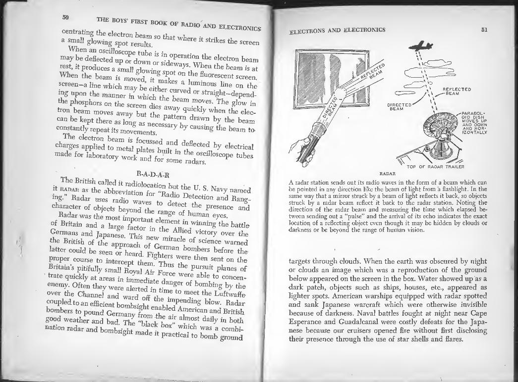
he boys first book of RADIO and electronics
S0 that Where “ «es the screen
ma^dXted^pTdo™ oJsa°Perati™the eIeCtr°” b*m rest, it produces a small <rl ■ d waYs- When the beam is at
8- ^Sha«~-creenl
screen-a line which may be either n !Ummous line on the ing upon the manner in which the be " straigbt-depend- the phosphors on the screen dies a ^ .™oves' Tbe glow in
tron beam moves away but the natT qUlck y wben the elec-
can be kept there as long as ntessattv ^ \ ^ bea™ constantly repeat its movements. ^ y causing the beam to
charges applS toTetal phtes'buSt/ft 'SCted,. ^ eIect*aI
made for laboratory work and for some td“s ^
R-A-D-A-R
The British called it radiolocation but the TT c m it Radar as the abbreviation for “R J Jf U‘ S< NavT named
mg- Radar uses and Ran^ character of objects beyond the presence and
Radar was the most important ele § f- human eyes' °f Britain and a large factor ^ the battI&
Germans and Japanese This A ied victory over the
the British of TZ -ience warned
latter could be seen of heard. FiStTweret™ ^ ^
proper course to intercept themU f then sent on the
Britain’s pitifully small Royal Air Fn"* ^ planes of trate quickly at areas in imm R- *■ were able to concen-
enemy. Often they were alertedhTr^r °f b°mbing V the
over the Channel and wtd off^L t0 T* the Luft^ coupled, to an efficient bombsipftf he, 11™pending blow. Radar
bombers to pound ^ British
good weather and bad. The “black b “ 'v? daily “ both
station radar and hombsighfnta^ft practical*!,, bomb ground
electrons and electronics 51
REFLECTED -BEAM
DIRECTED BEAM
,-PARABOL Ol D DISH MOVES UP AND DOWN AND HOR¬ IZONTALLY
' \ - TOP OF RADAR TRAILER
RADAR
A radar station sends out its radio waves in the form of a beam which can be pointed in any direction like the beam of light from a flashlight. In the same way that a mirror struck by a beam of light reflects it back, so objects struck by a radar beam reflect it back to the radar station. Noting the direction of the radar beam and measuring the time which elapsed be¬ tween sending out a “pulse” and the arrival of its echo indicates the exact location of a reflecting object even though it may be hidden by clouds or
•darkness or be beyond the range of human vision.
targets through clouds. When the earth was obscured by night
or clouds an image which was a reproduction of the ground
below appeared on the screen in the box. Water showed up as a
•dark patch, objects such as ships, houses, etc., appeared as
lighter spots. American warships equipped with radar spotted
and sank Japanese warcraft which were otherwise invisible
because of darkness. Naval battles fought at night near Cape
Esperance and Guadalcanal were costly defeats for the Japa¬
nese because our cruisers opened fire without first disclosing
their presence through the use of star shells and flares.

THE BOYS FIRST BOOK OF RADIO AND ELECTRONICS
When German submarines were destroying the ships that
kept England alive and supplied our overseas troops radar
helped to wipe out the underwater peril. Radar-equipped ships
and airplanes were able to discover submarines miles away-
by day or night. Radar had been so perfected before the end
of the war that it not only located the enemy but automatically
aimed and fired anti-aircraft and naval guns with superhuman
accuracy. Although radar was developed entirely for war, it
is not solely a tool of combat. It is saving many lives in peace¬
time applications. Its use aboard planes and ships and at air¬ ports increases the safety of travel.
Mounted in the cab of a locomotive, radar enables the engi¬
neer to detect other trains on the same track. Vessels provided
with radar can sail into a harbor during heavy fog without
colliding with other ships. At sea, radar warns of icebergs,
floating wrecks and other ships. Aboard an airliner, radar gives
pilots an accurate picture of their altitude at all times. It
reveals such hazards as tall buildings, mountains, other planes,
radio antenna, smokestacks and high tension wires. It will assist a plane to a safe landing in a dense fog.
No one man invented radar. It is largely the work of many
research teams. Radar had its beginning before World War II
but its great development took place during the war. Radar
was first discovered in the United States in 1922. Scientists
working for the Radio Division of the U. S. Naval Laboratory
observed that the signals from a radio station were interfered
with by objects moving in their path. So they set up a radio
receiver on the banks of a river to study the effects on signals
caused by boats passing up and down the river. With the knowl¬
edge gained from these experiments development work was
immediately begun on apparatus for detecting ships passing
between harbor entrances, or between ships at sea. The plan
called for a transmitter and a receiver at different locations.
In 1925 the apparatus was redesigned to have both the trans¬
mitter and the receiver at the same location. It made use of
ELECTRONS AND ELECTRONICS 53
the fact that many objects act as reflectors of radio waves. The
radio signals sent out by the radar transmitter were made to
strike the target and then bounce back to the receiver.
In 1930, the apparatus had been developed sufficiently to
pick up waves reflected back from planes passing overhead.
Four years later a means of measuring the distance between
the radar transmitter and the target was added.
The manner in which radar operates is more easily under¬
stood if you bear in mind that radio waves are reflected when they meet an obstruction.
TRANSMITTED OR MAIN PULSE
RANGE IN THOUSANDS OF YARDS
THIS PIP IS ECHO FROM TARGET AT 32,800 YARDS
THIS PIP IS ECHO FROM TARGET AT 49,200 YARDS
—SWEEP LENGTH IN INCHES
"ELAPSED TIME IN MILLIONTHS OF A SECOND
' SPLITTING A SECOND INTO A MILLION PARTS
The oscilloscope tube is the “heart” of a radar receiver. When in opera¬ tion, a radar transmitter sends out waves only a very small part of the time. Its waves are sent in intense bursts of short duration called pulses An oscilloscope tube measures the time it requires for the pulses to travel to a target and return as echoes. The outgoing pulses produce a “pip” on scope screen and so do their echoes. If the electron beam in the scope
screen sweeps across the screen for a distance of one inch in i/io,oooth ot a second: a distance of 2 inches between the pulse’s pip and its echo’s pips indicates that the echoes come back from an object 22,800 yards distant. The screen on the radar scope is graduated with fine lines so that the position of pips shows at a glance the distance of a target. A radar &rope tube can be arranged to present its information in different ways, lnat illustrated above is called A-scan presentation.

54 THE BOYS’ FIRST BOOK OF RADIO AND ELECTRONICS
The radar transmitter and receiver are located at the same
place. The transmitter sends out its waves in very intense bursts
of small duration called pulses. Each pulse may last only a
millionth of a second. After each pulse the transmitter waits
a few thousandths of a second before sending out the next
pulse and during that interval the receiver listens in.
The wave pulses sent out by the transmitter are focussed by
the antenna into a beam which can be pointed in any direction
like the beam of light from a searchlight. The beam is moved
by electrically operated machinery. It moves over the entire
region to be searched. Travelling at 186,000 miles a second, the
wave pulses go out into space, never to return unless they strike
an interfering object. In the same manner that a mirror struck
by a beam of light from a flashlight reflects it back, so do
reflecting objects such as ships, airplanes, water tanks, promi¬
nent buildings, mountain tops, etc., bounce back the radar
wave pulses. The radar receiver located near the transmitter
THE SCOPE SCREEN
IN A RADAR-EQUIPPED FIGHTER PLANE
The screen on a scope for B-scan presentation shows a fighter pilot the location of other planes which may be flying in the region up to 90 ° on either side of dead ahead. It also shows their distance.
electrons AND ELECTRONICS 55
detects these echo waves which bounce back. Near-by objects
give echoes very soon after the outgoing wave pulses leave the
antenna; objects farther away give echoes which arrive later.
The time which elapses between sending a pulse and receiving
its echo measures the distance of the object which is producing
the echo. The intervals between pulse and echo are very short
—they are measured in millionths of a second. Their exact
measurement is one of the great technical achievements of
radar. An object 2000 yards from a radar transmitter produces
an echo which arrives at the receiver only three millionths of a
second after the outgoing pulse left the transmitter. But the
radar measures this with such accuracy by using the time inter¬
val as an indicator of the distance that there is an error of only
15 or 20 feet.
You may wonder how the direction of the object or target
is determined. The antenna which sends out the beam of wave
pulses moves constantly up and down and around so as to
THE SCOPE SCREEN
IN A RADAR-EQUIPPED FIGHTER PLANE, Continued
C-scan presentation indicates planes ahead and whether they are to the right or left and above or below.

56 57 THE BOYS’ FIRST BOOK OF RADIO AND ELECTRONICS
thoroughly search an area. The strongest echo comes back when
the beam of pulses sent out by the radar is pointed directly
at the target. By noting the direction of the wave beam and
measuring the time which elapses between sending out a pulse
and the arrival of an echo from that pulse, the exact location
of the target or reflecting object becomes known even though
it may be hidden by clouds, distance or darkness.
o°
180°
RADAR IN A BOMBER
In addition to a scope which indicates the position and distance of other planes and targets, bombers are equipped with a scope which presents a map of the area being searched. This is called PPI-scan presentation and is used for search, harbor control, convoy keeping, ground controlled interception, navigation and bombing.
THE RADAR PROXIMITY* FUSE
An ingenious device called the radar proximity fuse was
one of the super-secrets of World War II. Until it was invented
there was no way to insure that an anti-aircraft shell would
explode at the right spot. It might burst before it reached its
target or some distance beyond. The ordinary fuse on an artil¬
lery shell can be set to explode the projectile at a certain time
after the shell is fired. Before the shell is loaded into the gun,
* Proximity is the state of being near or very close.
electrons and electronics
an artilleryman sets the fuse so that the shell will burst a
definite time after it is fired and hopes that the timing is correct
so that the shell bursts close to its target. A proximity fuse is
not pre-timed. Its projectile bursts only when it nears an ob¬
ject. Its burst is controlled by proximity to a target, not by
timing. The proximity fuse is a miniature self-powered radio trans¬
mitter and receiver no larger than a pint milk bottle. It is
enclosed in the nose of the projectile. It operates on radar prin¬
ciples. When the shell is fired from a gun, the proximity fuse
starts sending out its radio wave. When the projectile gets
within 70 to 100 feet of a plane or other target, the waves are
reflected back to the miniature receiver in the fuse. The re¬
flected waves are a signal that the shell is close to an object.
The receiver amplifies the signal and feeds it into an electron
tube called a thyratron. The thyratron acts as a power switch
and explodes the projectile at the right spot, close to the target.
Four miniature electron tubes are used in each proximity fuse.
It was no simple task to put such delicate parts into a projectile
and have them operate dependably. When fired from a gun, the
fuse must withstand the shock of a change in velocity from
0 to 2,000 miles per hour in a distance of 10 feet. But the
problem was solved successfully.
MARINE RADIO BEACONS
Radio first contributed to safety at sea by providing tele¬
graphic communication between ship and shore. Every mariner
and every person who travels on the sea recognizes radio s aid
to safety. It has been the means of saving the passengers and
crews of many disabled, sinking or burning vessels, which,
without radio, would probably have been listed simply as
“missing.” Rescues at sea, where aid was summoned by radio,
are headlined in the newspapers and the whole world soon
knows about them. But all the world does not know that radio
is working quietly and constantly to prevent marine mishaps.

58 THE BOYS’ FIRST BOOK OF RADIO AND ELECTRONICS
Accurate time signals and weather warnings are regularly
broadcast over the entire ocean area to give mariners a frequent
■check on their chronometers (the clocks used in calculating a
ship’s position) and on weather conditions. In addition, there
are numerous radiobeacons on the coasts of the U.S.A. Radio¬
beacons are an important aid to navigation. They enable vessels to check their positions by radio.
Radiobeacons are radio stations which send out radio signals
in all directions to guide marine navigators. They are operated
by the United States Coast Guard. The beacons are installed
at lighthouses, on lightships and at other points shown on the
marine maps called charts which navigators use. In this coun¬
try, radio signals are sent out from the beacons for 1 minute
RADIO DIRECTION FINDER
The antenna connected to the receiver of a radio direction finder consists of a coil of wire enclosed in a waterproof casing. The loop (left hand sketch) is mounted above decks or on the roof of the pilot house. The loop can be rotated by a hand wheel on the receiver. The receiver (see right sketch) is usually located in a cabin directly below the loop.
ELECTRONS AND ELECTRONICS 59
out of each 3 minutes and for one or two 10-minute periods
each hour during periods of good visibility. When there is fog
and when visibility is low, the radiobeacons send their signals
continuously. The signals, on wave frequencies of 285 to 325
kilocycles, are short and simple combinations of dashes and
dots which the station repeats without variation. Each beacon
has its own signal, different from that of all other beacons and
is easy to identify.
A ship must be equipped with a radio direction finder in
order to check her position by the signals of the radiobeacons.
The direction finder is simple and comparatively inexpensive,
many yachts and fishing boats are equipped. The device is an
ordinary radio receiver connected to a loop antenna arranged
for observing the direction of any station sending radio signals.
The loop antenna is a large coil of wire which is usually
mounted above the ship’s pilot house. It is fastened to the upper
end of a movable shaft which extends downward into the pilot
house. The lower end of the shaft is provided with a handwheel
and an indicator over a compass. The navigator or observer
can rotate the loop by turning the handwheel. If the loop is
turned, the indicator also moves.
To use the direction finder the navigator first picks up the
signals of a radiobeacon with the receiver. Then he turns the
loop and notes how the signal strength varies as the loop is
rotated. He continues to turn the loop until a point is reached
where the signal is lost entirely or nearly lost. This is called
“observing the minimum” and at this point the navigator notes
the position of the indicator above the compass. The indicator
is connected to the loop antenna in such a manner that when
the “minimum is observed” the indicator points directly to the
radiobeacon and shows its compass direction from the ship.
By ascertaining the direction of two or more radiobeacons
whose signals can be heard by the ship, and marking lines on
a chart which show their direction, the ship’s position is indi¬
cated. For example, a ship approaching New York can pick up

60 THE BOYS’ FIRST BOOK OF RADIO AND ELECTRONICS
radiobeacon signals from Fire Island, Ambrose Lightship and
Bamegat Lightship. When the “minimum is observed” for each
of these beacons, lines are drawn on a chart showing the direc¬
tion each beacon lies from the ship. The point where these lines
cross each other is the position of the ship.
The most powerful foghorn signals under favorable condi¬
tions may be heard 10 to 15 miles but their usual dependable
range is only 5 miles. During storms it is less. Coast lights are
visible for 15 to 20 miles and large lighted buoys for 9 to 12
miles in good visibility. Radiobeacons have a much greater
range of usefulness both in fog and clear weather than fog¬
horns and lighthouses or lightships. Radiobeacons vary in power
but many of them are reliable up to 200 miles. High-power
beacons have a range of 400 miles or more.
LORAN
Radiobeacons are an aid to navigation for medium distances.
Loran is a long range aid and is more accurate. It is not
affected by changes in the position of cargo booms, ventilators,
etc., as direction finders sometimes are.
The name “Loran” was coined from the words “LOng RAnge
Navigation.” The Loran system is an electronic aid which
enables a navigator to determine the position of his ship ac¬
curately and quickly, either day or night and under practically
all weather conditions. Loran signals are sent out 24 hours per
day and cover the major ocean shipping lanes of the world.
The effective range extends 750 nautical miles during the day
and 1400 mile/ at night. A ship’s position can be determined
in 2 or 3 minutes time by Loran in clear weather or foul. A
navigator needs clear skies to find the position of his ship by
a celestial observation on the sun or stars with a sextant. The
accuracy of an observation by Loran is comparable to that
which may be expected from good celestial observations. Loran
has an accuracy of better than 1 per cent of the distance of
the ship from the Loran stations. Thus, a ship 500 miles away
LORAN TRANSMITTING
STATIONS ^ PAIR A
LORAN TRANSMITTING
STATIONS PAIR B
LINE OF POSITION DETERMINED BY TIME DIFFERENCE BETWEEN SIGNALS RECEIVED FROM STATIONS B1 AND B2
LINE OF POSITION DETERMINED BY TIME DIFFERENCE BETWEEN SIGNALS RECEIVED FROM STATIONS A1 AND A2
VESSEL DETERMINING HER POSITION BY LORAN
from the stations would expect her Loran equipment to indi¬
cate a position well within 5 miles of the proper position.
Loran is used by airplanes as well as ships.
Loran operates on the following principles:
1. Radio waves which carry signals consisting of short pulses
are transmitted from a pair of shore-based transmitting stations.
The waves are radiated in all directions and are not sent out
in the form of a beam like radar waves. One of the pair of trans¬
mitting stations known as the “master” sends out each of its
pulses before the corresponding pulse from the second or
“slave” station.
2. The pulse signals are received aboard the ship or plane by
a Loran radio receiver known as a receiver-indicator. The
receiver performs in the same manner as an ordinary radio
receiver but is connected to a visual indicator, an oscilloscope,
instead of a loudspeaker. In this respect it is similar to a radar
receiver. The oscilloscope and its equipment is essentially an
“electronic stop-watch” which measures in millionths of a
second the difference in times of arrival of the pulse signals
from a “master” station and its “slave.”
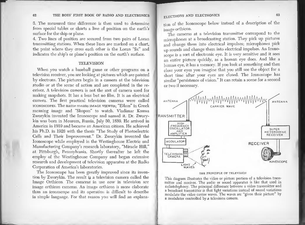
62 63 THE BOYS’ FIRST BOOK OF RADIO AND ELECTRONICS
3. The measured time difference is then used to determine
from special tables or charts a line of position on the earth’s
surface for the ship or plane.
4. Two lines of position are secured from two pairs of Loran
transmitting stations. When these lines are marked on a chart,
the point where they cross each other is the Loran “fix” and
indicates the ship’s or plane’s position on the earth’s surface.
TELEVISION
When you watch a baseball game or other programs on a
television receiver, you are looking at pictures which are painted
by electrons. The pictures begin in a camera at the television
studio or at the scene of action and are completed in the re¬
ceiver. A television camera is not the sort of camera used for
making snapshots. It has a lens but no film. It is an electrical
camera. The first practical television cameras were called
iconoscopes. The name means image viewer; “Eikon” in Greek
meaning image and “Skopon” to watch. Vladimar Kosma
Zworykin invented the Iconoscope and named it. Dr. Zwory¬
kin was bom in Mourom, Russia, July 30, 1889. He arrived in
America in 1919 and became an American citizen. He achieved
his Ph.D. in 1926 with the thesis “The Study of Photoelectric
Cells and Their Improvement.” Dr. Zworykin invented the
Iconoscope while employed in the Westinghouse Electric and
Manufacturing Company’s research laboratory, “Miracle Hill,”
at Pittsburgh, Pennsylvania. Shortly thereafter he left the
employ of the Westinghouse Company and began extensive
research and development of television apparatus at the Radio
Corporation of America’s laboratories.
The Iconoscope has been greatly improved since its inven¬
tion by Zworykin. The result is a television camera called the Image Orthicon. The cameras in use now in television are
image orthicon cameras. An image orthicon is more elaborate
than an iconoscope and its operation is difficult to describe
in simple language. For that reason you will find an explana-
ELECTRONS and electronics
tion of the Iconoscope below instead of a description of the
image orthicon. The cameras at a television transmitter correspond to the
microphones at a broadcasting station. They pick up pictures
and change them into electrical impulses; microphones pick
up sounds and change them into electrical impulses. An Icono¬
scope is a sort of electronic eye. It is very sensitive and it sees
an entire picture quickly, as a human eye does. And like a
human eye, it has a memory. If you look at something and then
close your eyes you imagine that you still see the object for a
short time after your eyes are closed. The Iconoscope has
similar “persistence of vision.” It can retain a scene for a second
or two if necessary.
ANTENNA
RANSMITTER
HIGH FREQUENCY
| OSCILLATOR AND
AMPLIFIER
XL
SUPER HETERODYNE
RECEIVER
MODULATOR
I RECEIVER
TELEVISION CAMERA
LIGHT S WAVES
KINESCOPE
THE PRINCIPLE OF TELEVISION
This diagram illustrates the video or picture portion of a television trans¬ mitter and receiver. The audio or sound apparatus is like that used in radiotelephony. The principal difference between a video transmitter and a broadcast transmitter is that light variations instead of sound variations modulate the video carrier waves. The waves are “given their picture” by a modulator controlled by & television camera.

64 THE BOYS’ FIRST BOOK OF RADIO AND ELECTRONICS
What the Camera Does. The images seen on the screen of a
television receiver come into the camera at the transmitter
through a lens like the lens in a photographer’s camera. There
similarity ends for the pictures are not focussed on a photo¬
screen Th, f 67 I"6 f°CUSSed °n an inSenious electronic wJrh'Jh 7 f°rm rere a miniature ™age of the scene on which the camera is focussed. The screen in an Iconoscope is
called a mosaic. It is a man-made electrical version of the
retinas in cur eyes. It is made of a thin sheet of mica which is >
coated wjth a film of metal on one side and covered on the
other side with millions of tiny silver globules. The globules are
—t" Each, °f them is a sma11 Photo cell-sensitive to hght. When light strikes the globules, they become electri¬
cally charged. Those globules which are in the lighter areas of
^?,!!U"e,f°CUSS(;d °n *e screen bec°me more charged than
An electron gun is
also an essential part
of an Iconoscope. It is
the same sort of elec¬
tric gun that is used in
an oscilloscope or in a
kinescope. It shoots out
a narrow beam of elec- :
trons like a water pistol
squirting out a stream
of water. Dr. Zworykin
l • t has called the electron I»am m an Iconoscope the “optic nerve of television.” He has
reuni”!, “ l° “ Paint brUsh” lhat ^ uP°n the -electric retma or mosaic screen in the Iconoscope. Electronics enei-
neers say that the beam "scans” the screen. If you look up
scan U1 ,he dictionary you will find that one of tts meanings
zztrrrtby pt>tat °r i° That* what the electron beam does. Starting at the upper left-hand
the globules in the darker areas.
the iconoscope in action
65 ELECTRONS AND ELECTRONICS
comer of the screen, it swings horizontally across the mosaic,
swings back to the left and repeats this motion. Each time
the scanning beam sweeps across the screen, it moves a little
farther down on the image. This downward and horizontal
motion of the beam is continued until the beam reaches the
bottom of the mosaic screen. Then it suddenly jumps back to
the top and begins its scanning again. The amazing thing is
that the beam silently and invisibly swings across the screen
from left to right 525 times in covering the screen from top
to bottom Thus it divides a picture into 525 horizontal lines,
or we might say, the electron brush paints a picture with 525
horizontal brush strokes. Each trip down the screen it paints
ouring'Vlyback ourVngFscanni
SCANNING
The Iconoscope does not view a whole picture instantaneously and a
Kinescope does not reproduce a whole picture instantly. Both Lust go
3 the Pr°cess called scanning in which the electron beam examines
left to rSL°tTs ltS rrV* 3 time- 7112 eleCtron beam ™ves from and iherfflLfh ? piCture is bein8 transmitted or formed
, ™es back to the left at almost instantaneous speed. An image is
the LTst ^ tW° ?Perations’ Paths of the electron beam second ™P3Sl ft mt£?laced ™th the paths of the beam in the skeLhLP i sketches above show the two passes. If one of the
he left toSht °n t0P fiheK°ther the black Iines representing me left to right swings of the beam will interlace. 6

66 THE BOYS’ FIRST BOOK OF RADIO AND ELECTRONICS
every other line and when it jumps back to the top to begin its
journey again it scans or fills in the lines it omitted on the last
trip. The beam scans the screen from top to bottom 60 times
a second. In other words, it paints 30 complete pictures every second.
When the electron beam swings back and forth over the
mosaic screen it discharges the individual silver globules, that
is, it causes them to lose their electrical charge. The individual
globules are charged to various degrees by the light and dark
portions of the picture. Discharging the globules forms a con-
KINESCOPE OR TELEVISION PICTURE TUBE
The Kinescope is a cathode-ray oscilloscope built for the special purpose of producing television pictures. The scopes used for radar and laboratory work are similar in principle but smaller. The focus coil focusses the electron beam; the deflection coil moves the beam.
67 ELECTRONS and electronics
tinuous stream of electrical impulses and these constitute the
“picture” or “video” signals. The video signals are sent into a
video amplifier where electron tubes increase their strength.
“Bewildering,” you may say if you do not understand television.
But it is really quite simple as well as wonderful.
Television Transmitter. Television broadcasting is carried
on at ultra-high frequencies. The very short carrier waves
from a television transmitter cannot be picked up by a receiver
located beyond the horizon. The range of a television station
is therefore limited to short distances in comparison with the
range of a radio broadcasting station. That is why so many
television transmitter antennas are located atop The Empire
State Building. A high antenna transmits farther than a low one.
The radio transmission of television is quite similar to radio
sound transmission. The transmitter which broadcasts the tele¬
vision pictures is called the video transmitter. The strengthened
picture signals from the video amplifier go into a video modu¬
lator. There they modulate the video oscillator circuit which
produces the video carrier waves. Three signals usually go out
on the carrier waves a fraction of a second apart. Two of them
control the horizontal and vertical movements of an electron
beam at the receiver; the other varies the intensity of the elec¬
tron beam and controls the black, white and halftone areas of
the picture which is reproduced on the screen at the receiver.
Sound usually accompanies the pictures, so a separate audio
or sound broadcasting transmitter is usually included with the
television transmitter.
Television Receiver. A television receiver detects and am¬
plifies the audio or sound signals and feeds them to a loud¬
speaker. It also detects and amplifies the control and video
signals from the video transmitter.
Kinescope. The amplified video signals are fed to a special
form of oscilloscope developed by Dr. Zworykin and called a
Kinescope. The Kinescope produces the transmitted pictures.
The name means “to watch movement”; “Kinema” meaning
movement in Greek and “Skopon” to watch.

THE BOYS’ FIRST BOOK OF RADIQ AND ELECTRONICS
The large funnel-shaped envelope of the Kinescope has an
e ec rongun at the small end and a fluorescent screen at the
large end. The electron gun shoots a slender beam of electrons
at the screen and the screen fluoresces wherever the electrons
strike. The signals that originate at the television transmitter
cause the beam to scan the screen of the Kinescope in perfect
step with the electron beam in the Iconoscope at the transmit¬
ter. Both beams move in the same direction at the same time.
The intensity impulses that originate in the Iconoscope cause
the intensity of the beam in the Kinescope to vary and paint
fluorescent pictures on the Kinescope screen. This is all done
Silently and without any moving machinery. In case you are
not duly impressed by the amazing ingenuity of a television
transmitter and jeceiver, here is one more fact. The transmitter sends out about 5,000,000 impulses every second in order to
make the picture which you see on the Kinescope screen.
PHOTO¬ SENSITIVE METAL
COLLECTOR ELECTRODE (ANOOE)
ELECTRONS
-LIGHT RAYS
LIGHT SOURCE
PHOTOTUBE
S^1nffVayS !Lrike the Photosensitive metal in the tube, electrons are thrown off from the metal. The electrons (represented by black dots in
ren can ^rrCnt flows in the tube circu't- This cur¬ rent can be amplified and made to operate a relay or other devices.
ELECTRONS AND ELECTRONICS 69
PHOTOTUBES
A tiny beam of light can be arranged so that if you intrude
upon it, it will ‘see” you and open a door for you, or if you
are an intruder it will sound an alarm. This is accomplished
with an electron tube. It has already been explained that the
flow of electrons in all radio tubes is controlled by means of
voltages applied to the grid or plate. There is another very im¬
portant class of electron tubes in which the flow of electrons
is controlled by light. These tubes are popularly called “elec¬
tric eyes.” Their technical name is phototube or photocell. A
phototube will respond to changes in the strength of light a
thousand times more rapidly than human eyes can and will
detect much smaller changes in the light strength. Phototubes
make talking motion pictures possible, also television. A photo¬
tube will automatically turn on lights when the sun goes down.
It will turn them off again when the sun comes up. It will watch
for smoke and ring a fire alarm if any appears. Phototubes are
used in burglar alarms, in animal traps, to count people, auto¬
mobiles or other objects which pass a given point, to control
automatic machines and printing presses, to bring elevators
level with the floor when they stop and in many kinds of labora¬ tory and control equipment.
Phototubes utilize the discovery that when light falls on
any one of a number of substances, electrons are emitted by
that substance. The production of electrons in this manner is
known as the photoelectric effect. The photoelectric effect was
discovered by Heinrich Hertz in 1887. Hertz never heard of
electrons but he noticed that an electric spark would jump
across a longer gap if the light from another spark was allowed
to fall on it. Hertz was unable to find any use for his discovery
but he recorded it so that it came to the attention of other
scientists. In following years many men investigated photo¬
electric effect and contributed the knowledge which made it possible to build phototubes.
In general appearance, a phototube resembles the common

70 THE BOYS’ FIRST BOOK OF RADIO AND ELECTRONICS
^ *ubes used ^ a radio receiver. There is more than one type. The illustration shows a No. 929. It contains two elec¬
trodes sealed in a glass bulb. The electrodes are connected to
contact pms which project from the plastic base. The air is
pumped out of the bulb before it is sealed. In a No. 929 tube
TheTalf8 photo^be’ a s™aI1 am°unt of argon gas remains! The half cylinder visible inside the tube is one of the electrodes
It is the photosensitive cathode and is made of a thin sheet
of copper which has been silver plated. The silver is covered
with a layer of cesium oxide and the cesium oxide is covered
SPROCKET HOLES
\ □ n □
□ □ □
□
PICTURE AREA
PICTURE AREA
□ □ □ □ □ a □
Kl VARIABLE AREA' SOUND TRACK
THE SOUND TRACK ON 35-MILLIMETER
MOTION PICTURE FILM
Twonlif^°rdedaT a1motion Picture film in the form of sound track Two types of sound track are in general theatre use. The film at the right hasc vanable area sound track, that at the left has variable density soS
Both types of sound track on film are produced photographically A microphone picks up the sounds to be recorded andchanges^he so^nd vibrations into electrical impulses. The impulses are amplSby electron tubes fed into an optical valve which causes a beam ofhght to fluctuate
^e fluctuatmg.beam is focussed on the film alongsidVthe pTctures' ^ a the film is developed the sound track appears.8\Vhen the film is run through the sound head on a motion picture projector the original sounds picked up by the microphone are reproduced. g
ELECTRONS AND ELECTRONICS 71
in turn with a layer of the rare silvery metal cesium. The plate
electrode or anode of the tube is the small rod in the center.
A phototube may be connected with a battery and a sensi¬
tive relay so that variations in the light will open or close the
relay. The relay may be arranged to ring bells, blow horns,
open doors, stop and start motors, or to control any sort of
device or machine. A phototube may also be connected to an
amplifier and the amplifier in turn to a loudspeaker as in talking
motion pictures.
MOTION PICTURE REPRODUCER SOUND HEAD
The sound head plus an amplifier and loudspeaker reproduce the sounds recorded photographically on motion picture film. In the sound head a narrow beam of light from a small brilliant incandescent lamp called the exciter lamp is focussed on a phototube. The light beam passes through the sound track on the picture film before it reaches the phototube. As the sound track moves through the beam, variations in the light and dark areas cause the light reaching the phototube to fluctuate. These light fluctuations correspond to the sounds recorded on the track. They cause the electrons emitted in the phototube to vary. The phototube is con¬ nected to an amplifier system which magnifies the variations in the elec¬ trons emitted in the phototube. The amplifier provides enough power to operate a loudspeaker located behind the picture screen.

72 THE BOYS’ FIRST BOOK OF RADIO AND ELECTRONICS
The positive terminal of the battery in circuit with the photo¬
tube is connected to the anode of the tube. When light falls
on the cathode of the tube, electrons are given out from it
instantly The technical way of saying this is, “When light!
falls on the cathode of the tube electrons are emitted instantly.”
The electrons flow across the space between the cathode and
wi!^ TtinUe t0 d° S° IonS aS h§ht remains °n the cathode. When electrons stream across from the cathode to the
anode, current flows in the tube circuit. This happens practi¬
cally instantly. When no light strikes the cathode, no electrons
eave it and no current flows in the circuit. The number of
electrons emitted from the cathode is dependent upon the
intensity of the light which strikes the cathode. An intense
light produces more electrons than a weak light and more cur¬
rent flows m the circuit. Less light produces fewer electrons
and results in smaller current flow. The instantaneous action
pk°t0tU^e Td lhG ^ that a chanSe in the %ht which on the cathode changes the current flowing in the circuit
are ot the utmost importance in the many uses of the phototube in talking motion pictures, television and industry.
PIEZOTRONICS
When certain crystalline materials are pressed or twisted
ey generate electricity. The electricity produced in this man¬
ner is ca ed piezo electricity and the crystals which produce
it are called Piezo-electric crystals. The Greek-derived word
t<piezo means press or squeeze. Piezo-electricity is literally
pressure-electricity.” Piezo, plus the word “electronics” is the
name of a new field in science. We come into contact with its developments every day of our lives.
Piezo-electric crystals have another remarkable property If
a piezo-electric crystal is placed between two metal plates and
^^pktes are charged electrically, the crystal will change in widtn, m length or in thickness.
Some of the substances whose crystals have marked piezo-
73 ELECTRONS and electronics
electric qualities are tourmaline, topaz, fluorospar, sugar, am¬
monium dihydrogen phosphate, Rochelle salt, lithium sulfate,
quartz, dipotassium tartrate and potassium dihydrogen phos¬
phate. The last six substances mentioned furnish the crystals
which are used most frequently in piezotronics. Of these,
Rochelle salt and quartz are used most extensively.
Pierre Curie, the famous co-discoverer of radium, and his
brother Jacques discovered the piezo-electric effect of crystals
in 1880. Their discovery remained a mere laboratory curiosity
and was not put to practical use until World War I. Then quartz
crystals became an essential part of submarine detection equip¬
ment. Soon thereafter quartz crystals were adopted in radio
communications to control the frequency of transmitters. A
A QUARTZ PLATE PREVENTS CHANGE
IN THE FREQUENCY OF A RADIO TRANSMITTER
The quartz is placed between two metal electrodes and enclosed in a plastic case as in the right-hand sketch.
radio transmitter must be provided with an automatic governor
to keep its frequency from changing. Although the piece of
quartz used for this purpose is called a crystal, it is not a whole
crystal. It is only a section of a crystal cut in the form of a flat
plate. When the quartz plate is placed between two metal elec¬
trodes to which an alternating current is applied, the quartz
vibrates and produces piezo-electricity. The pulses of piezo-

74 THE BOYS’ FIRST BOOK OF RADIO AND ELECTRONICS
electricity produced by the quartz vibrations act as pacemakers.
Their frequency controls the frequency of the radio transmitter.
The frequency at which the quartz vibrates depends upon its
thickness. If it becomes necessary to change the frequency of
a radio station, it is also necessary to connect a different quartz; crystal in circuit.
Grinding quartz crystals so that they will vibrate at a definite
frequency is an important branch of die radio industry.
TERMINALS ARE CONNECTED
' TO CRYSTAL
THUMBSCREW TO CLAMP NEEDLE
CRYSTAL CARTRIDO
TWO RUBBER STRIPS CLAMP THIS END OF ,
CRYSTAL SO IT CANNOT MOVE
PHONO PICKUP ARM FOR CRYSTAL CARTRIDOF
DOUBLE LAYER OF CRYSTAL COVERED WITH METAL FOIL
MUSIC FROM A ROCHELLE SALT CRYSTAL
Piezo crystals are in common use in phonograph pickups. Movement of the needle as it follows the groove in a record twists two plates cut from a crystal of Rochelle salt. The twisting creates pulses of piezo-electricity which are amplified and led to a loudspeaker. The two plates of crystal are clamped together. The double layer is called a “Bimorph.”
electrons and electronics
MICROPHONE
AMPLIFIER AMPLIFIER
PICKUP
^ recoro
PIEZO-ELECTRIC CRYSTALS BOTH RECORD
AND REPRODUCE
When an original wax recording is made sounds directed into a micro¬ phone connected to an amplifier produce electrical pulsations that cause a Bimorph (C) to move. A cutting stylus (CS) attached to the Bimorph cuts the wax. This action is reversed when a record is played. A needle (N) attached to a Bimorph twists the crystal as the needle point follows the wavy groove (GGG) in the record. The piezo-electricity generated by the crystal is fed to an amplifier. A loudspeaker connected to the ampli¬ fier changes the electric currents into sounds.
MODERN PHONOGRAPH RECORDS ARE MADE AND
PLAYED BY “PRESSURE ELECTRICITY”
The coming of radio sent the old hand-cranked phonograph
to the attic. It came back into the living room again a few
years later as the modem record player. The change and im¬
provement were brought about by developments which had
been made in electronic amplifiers and piezotronic systems.
Phonograph records are made by pressing a vinyl plastic into
metal molds called stampers. Until about 1920 the process was
begun by making an “original” recording on a revolving wax-
covered disk. The energy which cut the wax was only the
energy of sound waves. Original records were made by direct¬
ing the sounds into the large end of a horn. The small end of
the horn was closed by a diaphragm bearing a cutting stylus.
Sounds directed into the horn caused the diaphragm to vibrate

76 THE BOYS’ FIRST BOOK OF RADIO AND ELECTRONICS
and the stylus to move and cut a spiral wavy path on the wax-
covered disk. The wavy path corresponded to the wave pattern
of the original sounds but some sounds could not move the
cutting stylus with enough force to cut an exact facsimile in the
wax. When played back, the original recording would not pro¬ duce sounds exactly like the original ones.
The next step toward the production of commercial records
was to make a master” record. The original wax record was
MAGNET
WINDING
WINDING
VARIABLE RELUCTANCE CARTRIDGE WITH COVER REMOVED
POLE
''ARMATURE
ARMATURE "'NEEDLE (STYLUS) MOVES BETWEEN
POLES IN DIRECTION INDICATED BY
THESE ARROWS
PHONO PICKUP ARM POR
VARIABLE RELUCTANCE CARTRIDGE
VARIABLE RELUCTANCE PICKUP
All phonograph pickups do not utilize piezo-electricity. A variable reluc- tance pickup generates electric currents in somewhat the same manner that a dynamo generates currents. Movement of the phonograph needle or stylus varies the amount of magnetism which passes through two small windings. Variations in the magnetism generates currents which are amplified and fed to a loudspeaker.
SPACE BETWEEN COVER ANO CRYSTAL STACK FILLED WITH OIL
BRASS HOUSING
THIS END OF THE 'BIMORPH’IS CLAMPED BETWEEN TWO RUBBER BLOCKS
STYLUS CHUCK
TWISTER "BIMORPH*
UTTING TYLUS
PIEZO-ELECTRIC TRANSDUCERS
1. This is a piezo-electric crystal “cartridge” used for cutting records. In the illustration, the side of the cartridge is shown cut away so as to reveal its internal arrangement. The curved arrows represent the side to side motion of the cutting stylus produced by the twisting movements of the Bimorph.
2. This is a Sonar Transducer of the type called a hydrophone. It employs a piezo-electric element to convert electrical energy into sound energy and vice versa. It will perform both as an underwater microphone and as an underwater speaker. Part of the rubber cover is shown cut away in the sketch in order to reveal the crystal stack. This consists of several thin plates of lithium sulfate crystal stacked together with interleaved parallel connected foil electrodes. When the transducer is connected to a source of alternating current, the ends of the plates have a piston-like action, t he flexible rubber casing of the hydrophone is filled with oil so that the movement of the crystals is communicated to water through the oil and the waterproof rubber cover. By the same means, sound'waves in the water reaching the hydrophone are communicated to the crystal stack. 3- This is a typical transducer for depth finding systems. The side of the housing and rubber cover is shown cut away so as to reveal the crystal stack. Several thin plates of Rochelle salt or adp form the crystal stack.
.. inn r'vifi

78 THE BOYS’ FIRST BOOK OF RADIO AND ELECTRONICS
electroplated with a thin layer of gold and copper. This thin
metal shell was then stripped off the wax and backed by a
solid metal plate. This “master” was used to produce a “mother”
or several^ “mother” records in the case of a hit record. The I
stampers or molds used to press the records shipped to music ]
stores were made from the “mother” by an electroplating process.
Electronics has greatly improved the fidelity of modem re¬
cordings. Today the original recording is made on magnetic ]
tape and is a much more faithful recording than the old sound-
powered recording in wax. The tape recorder is then connected
to an amplifier which in turn operates a record cutter. The ]
record cutter engraves the sounds recorded on the tape onto a
lacquer disk in the form of a wavy groove. The cutter is elec- j
tncally powered and all the energy necessary for the cutting I
stylus is provided. Its power is not limited to the energy im¬
parted to a small diaphragm by sounds. A common type of
record cutter consists of a cutting stylus attached to a piezo- ]
electric crystal. The faintest sounds recorded on the tape result
in amplified electrical impulses which cause the piezo-crystal I
to move and move the stylus. Since a piezo-electric crystal con¬
nected to an amplifier moves a stylus with much more energy
than a sound-powered diaphragm it cuts a more faithful origi- !
nal recording. The metal “master” is made by electroplating
the lacquer original. The master is used to produce one or more
metal mothers.” Metal stampers made from the mother are
used to press out the commercial records from “biscuits” of vinyl plastic.
ULTRASONIC AND SUPERSONIC
Sound can be two things:
1. the sensation produced in the ear by vibrations.
2. energy produced by vibrations or alterations in pressure.
Most of the sounds which we hear are produced when air is
ELECTRONS AND ELECTRONICS 79
set into vibration, usually by some vibrating object which is in
contact with the air. Until a few years ago sound had limited uses. It provided
our principle means of communicating with each other, in the
form of music it furnished entertainment. Sounds within the
body other than the sounds of the voice were sometimes of
significance in diagnosing an illness. The sounds produced by
a machine were often an indication to a trained mechanic
whether the machine was in good working order or not. World
War II stimulated research and development of other uses for
sound. Sound became involved in almost every type of com¬
munication system used in the War. More recent research has
found countless new and useful applications for sound.
The words ultrasonic and supersonic are used in both sci¬
ence and industry.Ultrasonic is a term used to designate sounds
whose vibrations are so rapid they cannot be heard by human
ears. Ultrasonic sounds vibrate more than 20,000 times per
second. Young people with normal ears can usually detect
sounds vibrating from 20 to 20,000 times per second. In gen¬
eral, when sound vibrations are less than 20 per second or more
than 20,000 per second they are inaudible to human ears.
Middle-aged and elderly people have usually lost the ability to
hear the high-pitched sound of 20,000 vibrations per second, in
fact they cannot usually hear sounds above 16,000 vibrations
per second.
The terms supersonic and ultrasonic were used interchange¬ ably in the past to designate high-pitched sounds above the
range of the human ear. But over the past twenty years the
term supersonic has acquired new meanings. The word has been
adopted, particularly by the Air Force and others, to refer to
the speeds of objects moving in air faster than the speed of
sound. Many engineers and books on acoustical engineering*
use supersonic as the term for extremely intense sounds re¬
gardless of their frequency.
* An acoustical engineer is an engineer whose field is the science of sound.

80 HE BOYS FIRST BOOK OF RADIO AND ELECTRONICS
gentrbrp7onic and ■*—*. g-es, liquids and J-table changes in
jarring the dir, out of cl„thes clearing ,he XT"'2'"® mi,k’ fog and (Just and discovering invisible (1 almosPhere of s"'ol;e,
Products Co., n,anufacturesga™“sot dm ee'^e ^ penetrate solid metal and War d^vice whose sounds
these devices are used fa r T*” 'W Hundre* of
shops to find and locate faults in machinery Do" t railroad menting with a somewhat similar Xf are eXperi- locate shell fragments and ultrasomc instrument to
Ultrasonic *° detecl Stones, through the soft tissues of the twi" contro1 pass harmlessly
strilce more solid obT« s Hits ^ X “*° badc wh™ fully to pulverize gXo„e,X.0MCS hf<= been used success-
tha. this method Ly H * P««*> ehrmnate gallstones from human beta 8 operahons to
ingredients That >ob °f
separated again for years. When X ' jX X* tbey cann°t be sonics many molten metals that X *1 ,1R energy of super-
tofore can Z be bfantd fafa‘ SS a"Z ^
or Wer:,eneby»Tmr a energy to electrical enrra lCTOPh°ne, which converts sound trical energy to sound enjrov °U sPea^er which converts elec-
light energy to electrical enera ^ a P lotoce^' which converts
of transducers. However thevV^ f ^ generaI name create ultrasonics. A nL fG n0t ^ transducers used to vacuum tube oscillator ?is jFysta!’ connected to a creating ultrasonics A var and e®cient transducer for
arranged to produitlZT " and ^er are a few”times Z .Zndwhich Ornate from
per second to millions of times per second. When
81 ELECTRONS and electronics
electrical energy from this source is fed to a piezo-electric
transducer, the transducer produces sounds whose vibrations
have the same frequency as the alternating current.
UNDERWATER SOUNDS
HELPED TO WIN WORLD WAR H
A submarine which is cruising on the surface can send and
receive radio messages like any other ship, but a submarine's
radio equipment is useless when she is completely submerged.
The reason' for this is: radio waves are rapidly weakened in
passing through sea water. Sea water is a good conductor of
electricity. Fortunately water of any kind is a good medium for
the transmission of sound waves and consequently sound can
transmit- RECEIVE SWITCH
OSCILLATOR
UNDERWATER microphone LOUD-SPEAKER
i
POWER AMPLIFIER MODULATOR — AMPLIFIER
AMPLIFIER H DETECTOR - POWER
AMPLIFIER
AIR MICROPHONE
COMMUNICATION SONAR
AIR LOUD SPEAKER
Underwater sound waves are used to telephone and telegraph from ship ° ship, particularly by submerged submarines. In general, the same
underwater transducer is used as both a loudspeaker and microphone
theTece^ g°nneCtS the transducer to either the transmitting apparatus or

the boys first book of radio and electronics
«gfoidZ^rteTmTicaUon-A meth°d °f water communication It m°S. universally used for under-
And Ranging. Sonar embraleTainypes ofTndS°Unf NaVigation -ed aboard ships for uoderwaS 00™^^
SONAR-EQUIP¬ PED DESTROYER
SONAR WAVES TRAVEL TO SUB AND ARE REFLECTFO back to underwater microphone SUBMARINE
H OSCILLATOR
ex*6'
I reflected waves PRODUCE PINGS
D UNDERWATER LOU[>
ti-i&5ER microphone fE,NDS OUT SOUND WAVES ™ fP'CKS UP WAVES
REFLECTED BACK
_ heterodyne amplifier m horizontal
SWEEP
•
LA!
PIP 0
3 4
N SCREEN OF PIP ON SCREEN OF cathode RAY TUBE
TO 'subTE:S DISTANCE
direction and ranging sonar
by soNARei^eaprinc^pleCis ^e^ameasThat^f111131*116 ""l7 be determined sonar utilizes sound waves radar uses f RA°AR AWlth this difference: cycle alternating current is sent TnZ i '° WfeS‘ A short pulse of 2r
transducer sends out sound waves The 6 underwater transducer. The connects the transmitter and connects th(?UenCe SWltch lmmediately dis- any of the sound waves are refleeteH Rh i rfceiv1Ler to the transducers. If submarine, the transducer acts as a micronh J7 the ,hu11. of a submerged reflected or echo waves product a “Z" S T? pi°\S them UP- tube and a “pmg” sound from the air InnH^ ,KreCR of an oscilloscope
p.p o„ ,h« scope so™ i„dS*e“dSr^bSen
ELECTRONS AND ELECTRONICS 83
ships, whether they are surface ships or submarines. It includes
also apparatus for depth sounding, for navigational aid and for
locating and tracking submarines.
DEPTH
TRACE
PAPER RECORD
UNDER- MICROPHONE WATER LOUD¬ SPEAKER
LOUD SPEAKER
VERTICAL AMPLIFIER
SEQUENCE SWITCH
„ MOTOR
tTmrrKrtrTT‘"‘i’'»-'"l?n*rP"i',,lTVTrdkrrT'**™rrnxf**’ OCEAN BOTTOM
UNDERWATER MICROPHONE
ECHO DEPTH FINDINC SONAR
It is no longer necessary for a seaman to drop a weighted line into the water to find its depth. Depths from 5 feet to several thousand feet may be measured instantly by the sonar equipment of a ship. An underwater transducer is mounted flush with the hull of the vessel and directed downward. A short pulse of high frequency alternating current (10 to 100 kilocycles) sent into the transducer produces sound waves which travel to the bottom and are reflected back. When a pulse is sent, the sequence switch immediately connects the transducer to a recorder. The sound of a reflected pulse causes a pen on the recorder to make a dot on a moving strip of paper. The process is repeated every few seconds. Graph paper calibrated in fathoms is used on the recorder so that the position of the dots made by the pen indicate the depth of the water below the ship.
RECORDER
OSCILLATOR POWER
AMPLIFIER
,_1
X-RAYS
The discovery of the invisible penetrating light called X-rays
gave us an instrument of inestimable value for healing physical
injuries and treating disease. It provided a window of the body
through which the trained specialist can look to see that which
heretofore had been hidden from his eyes. X-rays are produced
when electrons travel at high speed and strike a metal target in

84 THE BOYS’ FIRST BOOK OF RADIO AND ELECTRONICS
a special form of vacuum tube. They were discovered by Wil¬
liam Konrad von Roentgen, Professor of Physics at Wurzburg Germany. Here is how Roentgen found X-rays •
In the early 1880’s, Professor William Crookes, an English
physicist, constructed some peculiar pot-bellied vacuum tubes.
He pumped part of the air out of some of the tubes. Other tubes
e connected to a special vacuum pump which drew out almost
a of the air so that only an infinitesimal fraction of the orig¬
inal air remained. When he passed a high voltage current from
an induction coil through his tubes, Professor Crookes noticed
that those which contained a comparatively large amount of
air became filled with luminous light and that those tubes con-
aming only a few molecules of air acted differently. No light
glowed within a high vacuum tube but its glass wall became
A MODERN X-RAY TUBE
hnlhhaA8 tubes were unreliable. The vacuum inside the glass factordAn tantahzinf way of changing. A tube which would work satis- aCtIf V , u y W0U d n0t necessarily do so on the day following Then
moved ht hb0iatTl 0f the General Electric Company ca Jan im proved tube named after its inventor, Dr. William D. Coolidge The making of X-ray pictures with the dependable Coolidge tube became
tibe wa3sS devS^f X PhotoSraPhs- Until the Coolidge tune was devised all X-ray tubes had a cold cathode. Coolidge tvoe tubls contain a hot cathode, heated by a filament. The hot cathode burnishes electrons more freely than a cold cathode. mrmsnes
85 electrons and electronics
fluorescent with a strange greenish-yellow light. Some sort of
invisible ray which came from the negative electrode (cathode)
in the tube struck the glass and caused the pretty fluorescence.
Crookes called the unknown rays cathode rays. He was amazed
when he found that the rays would bend under the influence
of a strong electromagnet brought near the tube. “It is radiant
matter,” he said, “which is striking the glass.” As this great
scientist gazed in awe at the cathode-rays he had discovered,
he was unaware that he had just missed discovering X-rays
and the electron.
About twenty years elapsed before it was known why the
glass wall of a high-vacuum Crookes tube glowed while the
space within remained dark. In the autumn of 1895, Professor
von Roentgen connected a large induction coil to a Crookes
tube. The tube was completely covered with a closely fitting
layer of black cardboard. When the apparatus was operated in
a completely darkened room, Roentgen made an astonishing
discovery. A paper screen coated with some compounds of
barium and platinum lying near the tube lighted up brilliantly
with a fluorescent glow. The fluorescence was observable when
the screen was six feet away from the apparatus. Such a weird
happening had never been noticed before. Roentgen soon con¬
vinced himself that the invisible agency which caused the
fluorescence originated at the point in the tube where its glass
wall was struck by the cathode rays and that it had passed
through the layer of cardboard covering the tube.
Upon further experiment he found that this invisible ray
would pass through many substances which were opaque to
ordinary light. It would go through stone, through thin layers
of metal, through living flesh and would affect a photographic
plate. The behavior of the new invisible rays was so puzzling
that Roentgen could not decide whether they were a form of
light or a sort of vibration, so he adopted the symbol used in
algebra for an unknown quantity and called them x-rays.

the BOIS FIRST BOOK OF RADIO AND ELECTRONICS
Electronics has many applications. Here are a few of them.
entertainment
Radio broadcasting
Television broadcasting Studio recording
Program pickup stations Booster stations
Home radio receivers
Home television receivers Amateur radio
Amateur radar
Amateur television
Phonographs Recorders
Sound motion pictures
COMMUNICATIONS
^Ties and vice versa ‘° ** *”d «* Radio teletype
Radio telephone and telegraph from ship to ship
Submarine cable booster and repeater equipment
Telephone repeater stations 4 P Telephoto transmission of pictures Facsimile
Police radio
Taxi radio
Truck radio
Railroad radio
Citizens’ radio
Air-ground communications
Navigation by radio and radar Airplane traffic control
Airplane Instrument Landing
87 ELECTRONS AND ELECTRONICS
INDUSTRIAL electronics
Automatic control devices for machines Automatic power distribution
Inspection in factories Quality control in factories
Electronic timers Computers
Color matching
Heating
Soldering'
Exploration for minerals and oil
Electronic instruments for testing and measuring
Weather observation instruments
CYCLOTRONS FOR ATOM SMASHING
ATOMIC ENERGY ELECTRONIC EQUIPMENT
MEDICAL ELECTRONICS
X-ray equipment
Diathermy
Electron microscopes
Electrocardiographs and other instruments for diagnosis
military electronics
Radio telephone and telegraph
Radio teletype
Radio facsimile
Weather observation
Radio and radar air and marine navigational aids Air warning radar
Fighter control radar
“Snooperscopes” for seeing in the dark
Gun and bomb control radar
Guy-laying equipment

THE BOYS’ FIRST BOOK OF RADIO AND ELECTRONICS
MILITARY ELECTRONICS (Continued) Guided missiles Proximity fuses Mine detectors Identification Radar bombing
Gun-sighting equipment Submarine detection
Chapter Five
RADIO TUBES- FEEDBACK AND REGENERATION
For very little money you can buy a marvelous scientific device—namely a “tube” for a radio receiver. This inexpensive creation of scientific research does its work with a precision and a certainty that are astonishing. Not all radio tubes cost so little. Several hundred different types are manufactured. They are used in the electronics industry as detectors of radio waves, as rectifiers (a rectifier acts as a valve and thereby changes alter¬ nating current into direct current), relays, switches, amplifiers of voltage and current and as generators of alternating cur¬ rents. When used for this last named purpose, a tube is termed an oscillator. Tubes are designed so that they are most efficient for one particular purpose. For example, a tube which is the best detector of radio waves is not the best amplifier and vice versa.
The electron tube, popularly spoken of as a “radio tube,” is truly the “heart” of modem radio. Carefully made estimates indicate that there are 900,000,000 to 950,000,000 radio tubes in active use devoted to entertainment (broadcasting and television) and 50,000,000 in use in industry and commerce. They range in size from tiny “acom” tubes which are about the size of your thumb nail and the sub-miniature tubes used in hearing aids to the large water-jacketed transmitting tubes
89

90 THE BOYS’ FIRST BOOK OF RADIO AND ELECTRONICS
termed ‘bottles” which are sometimes five feet high. Materials
from every comer of the earth are required in manufacturing electron tubes. 6
When tungsten, certain other metals and metallic oxides are
heated to high temperature in a vacuum they yield large num¬
bers of electrons. This simple method of producing electrons
makes it possible to build the electron tubes used in radio. A
radio tube consists of a cathode which supplies electrons when
heated and one or more additional electrodes mounted in an
evacuated glass bulb or metal shell. The bulb or shell is termed
the envelope” in scientists’ language. The additional electrodes
control and collect the electrons supplied from the hot cathode.
The wonderful accomplishments of radio tubes are the result of their ability to control almost instantly the movement of
millions of electrons supplied by the cathode and to do this
with the expenditure of only an infinitesimal amount of con¬ trol energy.
DIODES, TRIODES, ETC.
Tubes having two electrodes or elements like the original
Fleming valve are still employed in radio. They are called I
diodes and are used as detectors and as rectifiers of alternating currents. 6
The audion which Lee De Forest invented is a three-electrode
tube or triode. Its three electrodes consist of a cathode, a grid and a plate or anode. The third electrode, or grid, is all im¬
portant because it is the control electrode. The electrical
charge on the grid controls the electrons in their flight from the
cathode to the plate. When the grid has sufficient negative elec¬
trical charge it repels electrons and blocks their flow across the
space between the cathode and plate. On the other hand, if the
gnd has a positive charge, it attracts electrons and increases
their flow from the cathode to the plate. When a triode goes
to work in a receiver, amplifier, etc., electrical charges on the grid cause the tube to fulfill its purpose.
HAJDIO TUBES-FEEDBACK AND REGENERATION 91
RESEARCH IMPROVED RADIO TUBES
i. Modern radio tubes are far more efficient than the original De Forest
audion (lower left). 2. The three elements of the audion consisted of a
loop-shaped filament, a flat grid and a small flat metal plate. 3. The grid
in a modern triode is usually a spiral wire which completely surrounds the
cathode, and the plate is a metal cylinder or oval surrounding the grid.
4. Many modern tubes have more than one grid; tetrodes have two,
pentodes have three. The cylinder plates in the illustrations above are
shown cut away to reveal the grids and cathodes.
For a few years after the audion was invented, triodes were
the only electron tubes used in radio, but the coordinated
efforts of engineers and craftsmen have resulted in many im¬
provements. For example, it was discovered that tubes with
more than three electrodes would perform better in some cir¬
cuits. Consequently, many of the tubes used in radio receivers

THE BOYS’ FIRST BOOK OF RADIO AND ELECTRONICS
today have five electrodes. They are called pentodes. Tubes with four electrodes are called tetrodes. Di, tri, tetr and pent are from Greek words meaning respectively “two,” “three” four, and fiye.^ Diode means “two electrodes,” Mode means
ree electrodes and so on, the name of the tube thus reveal¬ ing how many electrodes are inside its glass bulb or metal shell.
MULTI-UNIT TUBES
Tubes with the electrodes of more than one tube enclosed in the same bulb or shell are called multi-unit tubes.
TWO KINDS OF CATHODES
The cathode m a radio tube does not supply electrons unless it is hot. An electric current is used to heat the cathode. A hlament-cathode or directly heated cathode is a wirejieated
tungsten
directly heated filament type
CATHODE IS A TUBULAR SLEEVE INSUL¬ ATED FROM THE FILAMENT —- CATHODE
■ FILAMENT INSIDE SLEEVE
INDIRECTLY HEATED HEATER TYPE
TWO KINDS OF CATHODES
The figment serves as the cathode or electron emitter in radio tubes designed for operation on direct current (left). The cathode in tnhps
htr/bv a^ims rr- » .1 , ^ V £‘ filament of an AC tube is termed a “heater” The
thehheaterUPP ieS eleCtr0nS when its temperature is raised sufficiently by
93 RADIO tubes-feedback and regeneration
by the passage of an electric current. A heater-cathode, also called an indirectly heated cathode, consists of a wire filament called a heater enclosed in a metal sleeve. The passage of an electric current through the heater causes it to become hot and heat the sleeve. The outside surface of the sleeve carries an electron-emitting material which supplies electrons when the
sleeve becomes hot. The two types of cathodes each have a special purpose.
Directly heated filament-cathodes require comparatively little heating current. They are used in tubes designed for battery operation in order to impose as small a drain as possible on the batteries. Directly heated filament-cathodes respond very quickly to fluctuations in the heating current. With each fluc¬ tuation there is a change in the number of electrons released. Consequently, they cannot be used on alternating current with¬ out producing a “hum” in the circuits.
Heater-cathodes are used in tubes designed for operation on alternating current. The filament in this type of cathode does not supply any useful electrons—it is used only to heat the sleeve. The sleeve does not respond quickly to changes in the heat produced by the filament and therefore there are no rapid fluctuations in the electron supply which would cause a hum.
OUTSIDE AND INSIDE A RADIO TUBE
Hundreds of radio tubes of different sizes, characteristics and purposes are manufactured by the tube makers. These are listed in catalogs or booklets which contain a basing diagram and a description of each tube. Ask at your library for the standard list of tubes for amplifiers, radio receivers and tele¬ vision receivers. It contains data on current types as well as information on discontinued types in which there still may be
some interest. All electronic apparatus, employing electron tubes, must be
wired so as to comply with the basing diagrams. Every young

94 RADIO tubes-feedback and regeneration 95
THE BOYS FIRST BOOK OF RADIO AND ELECTRONICS
THE BASES OF RADIO RECEIVING TUBES
AND THEIR CORRESPONDING SOCKETS
electronics experimenter must learn how to interpret tube
basing diagrams. The illustration on page 95 provides the bas¬
ing diagram for an 1G4/GT tube. This tube is no longer manu¬
factured but is illustrated and discussed here because of its
simplicity. The 1G4/GT is a triode designed to be a detector or
a voltage amplifier in small battery-operated receivers. It is
simpler to describe and understand than a multi-unit tube.
The lower end of the glass envelope which encloses the ele¬
ments of an 1G4/GT tube is cemented in a molded plastic base.
Seven contact pins extend from the underside of the base. The
elements in the glass envelope are connected to these contact
pms. The numbered circles in a basing diagram represent the
pms. Two of the pins (Nos. 2 and 7) on an 1G4/GT are con¬
nected to the terminals of the filament. They are also marked
F and F in the diagram. The filament serves as the cathode in
a tube designed for battery operation. The grid and plate of an
1G4/GT are connected to pins 5 and 3 in the diagram. 5 and 3
are also marked G and P (abbreviations for “grid” and “plate”).
Pins marked NC, in this case pins Nos. 1, 4 and 8, have nothing
connected to them.
The mirror-like surface which may be present on the inside
of tubes having a glass envelope results from a chemical called
a “getter” used in producing a high vacuum. Only about
1/100,000,000 of the original air in the tube remains. A high
vacuum makes receiving and amplifier tubes more efficient.
Even minute traces of air, if left in a tube, would interfere with
the electrons which pass across the spaces between the ele¬ ments.
bottom view of CONNECTIONS
1G4 GT TOP VIEW OF TUBE CONNECTIONS
TOP VIEW OF OCTAL SOCKET
BASING DIAGRAMS AND SOCKET FOR IG4/GT TRIODE
The elements in a radio tube are connected to contact pins which project from the bottom of the tube. Diagrams of this type show which element is connected to which pin. The numbered circles represent the pine
TUBES FOR HIGH FREQUENCIES
When radio tubes are used in circuits which operate at the
higher frequencies, certain properties of the tubes which were

VERY HIGH FREQUENCIES REQUIRE SMALL TUBES
The elements—cathode, grid, plate, lead-in wires, terminals, etc.—in a radio tube have an electrical quality called capacitance. This effect is objectionable in many circuits, especially those designed for very high
ThC caPadta"Ceo°f 3 tube can be educed by mak.ng the tube and its elements small. Small tubes have less capacitance, weigh less and take up less space. Small size tubes called miniature and sub-miniature
^beaSkare U^d,m reCei','frr d1CSlgned for very hiSh frequencies. Small tubes are also useful in small light-weight receivers, amplifiers and other elec-
amp,lfiers “ hearing aids « equipped with esub-
negligible at lower frequencies become important. Therefore it is necessary to build special tubes for high frequencies.
Miniature Tubes. It is customary to use miniature tubes in
short wave receivers for frequencies below 200 megacycles.
Miniature tubes are used also in many receivers designed for
the medium frequencies. These small tubes are about %-inch
in diametfer and are all glass tubes which are called acorn tubes
because of their shape. No base or contact pins are used on an
acorn tube. Connections are made directly to the electrode leads where they project from the side of the tube.
Lighthouse Tube. This tube was designed to overcome the
effects of leads to the electrodes on high frequencies. Short
heavy metal rings are used instead of leads. The electrodes are
97 RADIO tubes-feedback and regeneration
as small as possible and are spaced close together so that it takes
little time for the electrons to travel from the cathode to the
plate. Its physical appearance gave the tube its name.
Cavity Magnetron. The most efficient radar makes use of
very high frequencies. Tubes with a grid cannot be used as
oscillators to produce the extremely high frequencies which
create the microwaves employed in radar. One of the milestones
in electronics was the development of a mysterious radio tube
in 1940 at the University of Birmingham, England. It solved the
problem of producing microwaves (radiowaves 50 centimeters
and shorter). It made microwave radar practical for the first
time. Called “maggie” by radar operators, its proper name is
• cavity magnetron. “Maggie” was a super secret during World
War II. Microwaves enabled the Allies to inflict many devas¬
tating surprises upon German and Japanese armed forces. In
appearance a cavity magnetron bears no resemblance to the
common radio tube. It is a special form of diode which operates
under the influence of a strong magnet, hence the name magne¬
tron. The magnet causes the electrons which are emitted from
the cathode to move in a spiral path before they reach the
anode. The cavity magnetron consists of a cylindrical cathode
surrounded by a massive copper anode. The anode has several
keyhole-shaped cavities cut in it. The electrons emitted by the
cathode are whirled in the cathode chamber past the slots in
the anode by the action of the magnet. As the electrons spiral
past the cavities, they cause the electrons in the cavities to
oscillate in much the same manner as the air in a bottle is made
to oscillate and whistle by blowing a stream of air across the
mouth of the bottle.
The remainder of this chapter explains more fully the action
of a radio tube. It may be uninteresting to readers who happen
to be more concerned with building radio apparatus than with
the principles of electronics. To many it may be difficult to
understand. If you find it so, skip it. Turn to the next chapter.
For those who wish to make radio a permanent hobby or

98 THE BOYS’ FIRST BOOK OF RADIO AND ELECTRONICS
"fwT curiosity- here is an explanation. First, it should be stated that it is not difficult to explain the
action of an electron radio tube to an engineer or to anyone
who understands the mathematical curves called graphs which
are used by engineers. But it is not possible to give a simple
and at the same time complete technical explanation of the
action of an electron radio tube with words only. Without
cSt^rr011 Wh°1Iy accurate because it is not | omp ete. Graphs have been omitted because they are too
technical for this book. 7 j
To make the explanation as clear as possible it is necessary 1
to begin by repeating certain facts which have been stated elsewhere m this book. i
A three-electrode vacuum tube containing a cathode (pro- '
ducer of electrons), a plate (collector of electrons) and a grid 1
(controHer of electrons) is called a Mode. The grid is a screen
attice-hke affair containing openings through which elec-
trons may pass. Many vacuum tubes contain more than one
grid. The behavior of multigrid tubes is in many respects simi-
kr to that of a Mode. A Mode is simpler, easier to understand. We will explain it.
The three circuits which are necessary in order for a triode
° play its part m a radio receiver are shown in an illustration
nearby. The tube represented is the filament-cathode type
which operates on 1.5 volts. It has long been the custom to call
the battery which supplies current to the filament, the “A”
Prateed,ea"B-tbatterythe '**** WhiCh ‘° the
When a radio tube is in action one of the fundamental laws ot electricity is at work. It is that:
Negative charges of electricity repel negative charges and
positive charges repel positive charges, but positive and nega¬ tive charges attract each other. 5
Electrons are tiny particles of negative electricity and in
obedience to the above law are attracted by a positively
RADIO TUBES-FEEDBACK AND REGENERATION 99
charged electrode and repelled by a negatively charged
electrode.
With this knowledge we can get a mental picture of the fun¬
damental action which takes place when the tube is operating.
When the B battery is properly connected in the plate circuit,
the positive terminal of the battery is connected to the plate
and the negative terminal of the battery to the cathode. This
results in a charge of positive electricity on the plate.
As soon as the A battery connected to the cathode heats the
latter to sufficient temperature an invisible group of tiny par¬
ticles forms close to the cathode. The invisible group is a group
of free electrons, a group of tiny particles of negative elec¬
tricity, which have broken through the surface of the cathode.
The velocity of the electrons as they emerge from the hot
cathode is very low and they do not have energy to travel far
unless they are assisted. They tend to stay close to the cathode
or return to it unless they are coaxed away. Since the plate is
charged positively it attracts electrons. If the grid has no charge
ANTENNA
current to plate circuit
THE CIRCUIT OF A TRIODE DETECTOR
The circuit has three parts: l. the grid circuit indicated by light lines; 2. the filament circuit indicated by heavy lines and 3. the plate circuit indicated by broken lines.

100 THE BOYS FIRST BOOK OF RADIO AND ELECTRONICS
a few of the electrons pass through the grid and reach the plate,
ihe word few in the preceding sentence is important. If the
grid has sufficient negative charge none of the electrons get
through the grid to reach the plate. When no electrons pass
rom the cathode to the plate, no current from the B battery
flows m the plate circuit. The electrons are repelled back to
the cathode from which they emerged. Since the grid is nearer
die cathode than the plate, a positive charge on the grid will
have much greater pull on the electrons than an equal positive
charge on the plate. Under this condition the combined attrac¬
tion of the grid and plate causes a large number of electrons
to move away from the cathode, pass through the grid and
reach the plate With the passage of a large number of electrons
rom the cathode to the plate, there is considerable flow of cur¬ rent from the B battery through the plate circuit.
After all this preliminary explanation, we now come to what
occurs m a tube when it is used as a detector in a radio receiver.
e currents generated in a receiving antenna by incoming
signals are alternating currents, that is, alternately positive and
negative. If the grid circuit of a triode detector tube is con¬
nected to an antenna so that incoming signals are impressed
upon it, the charge on the grid will vary in accordance with
the signals. So will the number of electrons passing from the
cathode to the plate-likewise the volume of current flowing in
the plate circuit The circuits can be so adjusted that even
though very feeble signals come from a transmitting station
the variations in current flow in the plate circuit will produce plainly audible sounds in a telephone receiver.
AN EXPLANATION
OF FEEDBACK AND REGENERATION
When Edwin H. Armstrong disclosed his invention called feedback or regeneration, he showed how to make the triode a
much better detector than it had ever been before and he also
showed for the first time how the tube could be made to oscil-
RADIO TUBES—FEEDBACK AND REGENERATION 101
^plS^tltn it wafusX3 "
rftcould be “p Feedback 4“““ ^
circuit of a radio tube and WL fk ? the output or plate
circuit and, when it reaches the nl t ^ “t° the input or
form, sends it back again to the grid cbcSt. aga'" ™pI“ied
rp, . , electromagnetic induction
and shows howeteT^^tansferred1fSm ^ eIect,romagnetic induction netism. 67 ansrerred from one coil to another by mag-
The^ihultratiDirshows Tfeedh^ 1° 3 feedback
tbe ^generative^eraire^d^scribed'^Iate/'The1/0^31 e'sed *n complished by means of a coil called a ^clS- ” “ 3°-
fcvisiSy^ *£££ fr°m “ 0011 » by an oasiIyfi„|„ut Xt 'Wr MAGNEnC You can ment Wrap two i"duCtion is by an experi-
p two layers of paper around a large iron nail. Then

102 THE BOYS’ FIRST BOOK OF RADIO AND ELECTRONICS
wind about 40 or 50 turns of insulated wire around the nail
near one end. Wind a second similar coil of insulated wire
around the nail near the other end. Connect one coil to a tele¬
phone receiver and one wire of the other coil to the positive of
a dry cell. Listen in the telephone while you tap the uncon¬
nected wire of the second coil against the negative terminal of
the dry cell. When current from the cell is flowing steadily
through the coil, you will not hear anything in the telephone
receiver. If you make and break the circuit so as to shut the
The feedback principle, also called regeneration, feeds energy from the plate or output circuit back into the input or grid circuit. The action is explained at greater length in the text. In the circuit shown above, the transfer of energy from the plate circuit to the grid circuit is accomplished by two coils employing electromagnetic induction. Feedback may also be accomplished by a resistor or a condenser. The light lines indicate the grid circuit; the heavy lines are the filament circuit and the broken lines are the plate circuit.
RADIO TUBES-FEEDBACK AND REGENERATION 103
current on and off, you will hear a clicking sound. The clicks
are caused by current induced in the coil connected to the tele¬
phone receiver. The current is induced only when the current
in the coil connected to the cell is increasing or decreasing.
In the feedback circuit which is illustrated, the tickler coil
is connected to the plate circuit and placed near a “grid coil”
connected to the grid. The tickler coil transfers energy to the
grid coil by electromagnetic induction. In other words, current flowing in the tickler coil induces current in the grid coil. The
current induced in the grid coil changes the charge upon the
grid of the triode and changes in the charge on the grid produce
changes m the current flowing in the plate circuit and tickler
coil. It the grid coil is connected so that it receives signals from
an antenna, the regenerative or feedback action greatly builds up the signal strength.
If the feedback circuit is adjusted so that the “feed-back”
energy travelling from plate circuit to grid circuit and back
again is properly timed, the process will repeat itself very
rapidly and continue to do so indefinitely. The circuit is then oscillating.
ELECTRON TUBE OSCILLATORS
A very important application of electron tubes is in the gen¬
eration of alternating voltage and current. When used for this
purpose it is called an oscillator. An oscillator can be adjusted
to generate alternating currents of any frequency desired rang¬
ing from a few cycles per second to several hundred million. An
oscillator does not actually generate current, for example like
an alternator generates current. The tube and its auxiliary cir¬
cuits change direct current into alternating current. It converts current fed to it rather than generates.
There are about a dozen kinds of vacuum tube oscillators.
One of these is the feedback oscillator-it was the first. There are six well-known varieties of feedback oscillator
Since the day when Rudolph Hertz first succeeded in pro-

104 THE BOYS’ FIRST BOOK OF RADIO AND ELECTRONICS
TRANSMITTING TUBES
A transmitter transforms power supplied by AC lines, batteries or genera¬ tors into radio-frequency power which is made to carry intelligence. Transmitter tubes may be diodes, triodes, tetrodes or pentodes. Large transmitter tubes produce large amounts of heat which must be removed by natural air currents, forced-air cooling, or water cooling. 1.' The tube at the left is a power tetrode with an output of more than 3,000 watts. 2. The tube in the center is a triode. 3. That at the right is a “light¬ house” tube for high frequencies.
ducing electric waves, many methods of generating the high-
frequency currents required in radio have been employed. All
of them have been discarded in favor of the vacuum tube oscil¬
lator. It is the most satisfactory—it is portable, has no moving
parts and is comparatively inexpensive.
The power of a single oscillator is quite limited. When more
power is needed the high-frequency currents produced by the
oscillator are sent through amplifier tubes and strengthened
before they reach the antenna.
RADIO tubes-feedback AND REGENERATION 105
Electron-tube oscillators have uses other than as sources of
high-frequency current for transmitters. They have become an
indispensable part of the equipment of scientific, educational
and commercial laboratories. The medical treatment called
diathermy utilizes an electron tube oscillator. The Cyclotron
uses an oscillator. An oscillator is part of every superheterodyne
receiver.
All television receivers and the best broadcast receivers em¬
ploy the circuit invented by Professor Armstrong which he
called the superheterodyne. In the superheterodyne, one tube
acts as an oscillator. It does not send out radio waves but pro¬
duces high-frequency currents of a different frequency from
the incoming signals. The receiver-produced frequency is mixed
with the incoming frequency from the antenna. The result is a
new “beat frequency” caused by the interaction of the two fre¬
quencies. The “beat frequency” can be amplified more effi¬
ciently than the frequencies produced in the antenna by incom¬
ing signals and is the reason why a “super” is so sensitive and
selective.
CAVITY MAGNETRON
This is one form of the oscillator used to produce the very high frequen¬ cies which generate the microwaves used in radar.

Chapter Six
THINGS YOU SHOULD KNOW ABOUT THE
PARTS AND MATERIALS USED TO BUILD
RADIO AND ELECTRONIC APPARATUS
An automobile is produced by assembling an engine, carbu¬
retor, starter motor, radiator, generator, gears, wheels, axles
and other parts in a frame. In much the same way, radio and
electronic apparatus is built by assembling various coils, trans¬
formers, condensers, sockets, resistors, etc., on a base or chassis.
A few of the parts used in assembling the radio and electronic
equipment described in this book have been designed for you
to make yourself. Most of the parts you will have to secure
ready-made, by purchasing or by salvaging from dismantled
radio equipment. It is not necessary to know a great deal about electricity or
radio in order to build radio and electronic equipment. It is
only necessary to follow diagrams and instructions carefully.
But if you intend to build radio and electronic equipment it will
be helpful to learn everything possible about the various re¬
sistors, condensers, tubes, etc., used in this work. When you
understand the construction of these parts and their purpose, it
will be easier to construct and operate your equipment. Last,
but not least, this knowledge will make your hobby much more
interesting.
RADIO and ELECTRONIC APPARATUS 107
This chapter is intended to make you acquainted with the
principal parts, materials and tools you will use. All parts,
materials and tools are standard and are manufactured in large
quantities. They are relatively inexpensive.
4 Any firm that sells radio equipment or issues a general catalog
of radio supplies can supply the parts or materials called for in
this book. It is suggested that you send for the catalogs of the
mail order radio firms which advertise in radio and popular
scientific and mechanical magazines. You can buy anything you
may need by mail.
RESISTORS
If you turn a factory-made radio receiver upside down and
look at the underside you will see a maze of colored wires and
small paper covered cylinders. The small cylinders with three
or four colored bands near one end are resistors and they are
used to oppose the flow of electricity and reduce the voltage in
certain parts of circuits. The resistance of a resistor, or in other
words, its ability to oppose an electric current, is measured by
a unit called an ohm. Resistors are made in various sizes and
in varying resistance ranging from 0.1 to 22,000,000 ohms. Inci¬
dentally, 1,000,000 ohms is called a megohm. Radio engineers
use the term meg instead of million when speaking of ohms.
22,000,000 ohms is 22 megohms in radio terms. The terminals
of the resistors made for radio receivers, amplifiers and other
instruments, if they are required to carry only a very small cur¬
rent, have a tinned wire at each end. The body of the resistor
is marked with colored bands which indicate its resistance. The
colors conform to a standard system adopted by the Radio
Manufacturer’s Association. Each color represents a number or
figure. Some one may give you a few resistors or you may dis¬
mantle an old radio to obtain parts and wish to identify the
resistors according to their resistance in ohms. Therefore the
R.M.A. color code is illustrated here.
106

THE BOYS’ FIRST BOOK OF RADIO AND ELECTRONICS
BLACK BROWN RED
ORANGE YELLOW GREEN BLUE VIOLET GRAY WHITE
I-WATT
2-WATT
BLACK BROWN REO
ORANGE YELLOW
GREEN BLUE VIOLET GRAY
WHITE
l/g-WATT
GOLD . 5 o/ SILVER * 1OW0
NO BANDi 20%
BROWN O RED OO ORANGE OOO
YELLOW OOOO GREEN OOOOO
BLUE OOOOOO GOLD MULTIPLY
BY .1
SILVER MULTIPLY BY .Ol
RESISTOR COLOR CODE
SedW coTor bandfTm]\dther riked 0n * with numerals or indi- thai k • interpret the color bands hold the resistor so
iumeS ib«e„Ti?,lh/ b“dS “ Ead> ^ fori
with rS™bLd °'e ,ha" ,es,s,0,s wi,h a silv" f“rth b=»«l o,
capifc'ty °f a rcs“t0r b>’its sra A W-watt resistor
."'';ara1a0",L^1sZCh 3! 3 -Wa,t a"d * “ »«=>■
PADIO AND ELECTRONIC APPARATUS 109
VOLUME CONTROLS
Most radio receivers are equipped with a knob to regulate
the volume of sound produced by the receiver. The common
volume control is a variable or adjustable resistor mounted in
a plastic housing with a metal cover. It is equipped with three
terminals to which wires can be soldered. The two outside
terminals are connected to the ends of the resistor. The center
terminal is connected to a movable contact which slides over
the resistor when the shaft to which it is attached is tinned.
The control can be used to increase or decrease either the resistance or the voltage in a circuit.
VOLUME CONTROL TERMINALS
SWITCH TERMINALS
KNOB
ADJUSTABLE SHAFT
-^A/yvvw^- BUSHING
SYMBOL SWITCH
A VOLUME CONTROL AND ITS SYMBOL
Volume controls are resistors whose resistance can be varied by turning a knob. They can be connected so as to control either the current or the voltage in a circuit.

110 THE BOYS’ FIRST BOOK OF RADIO AND ELECTRONICS
surfaces separated and insulated from each other by a layer of insulating material called the dielectric.
Condensers store energy and discharge it in the form of elec¬
tricity. An explanation of how they do this would be rather
complicated and perhaps not of great importance to a radio
novice. For practical purposes, think of a condenser as a simple
and useful device which will store energy for a short time and
when included in a circuit will allow an alternating current to
pass but completely block a direct current.
TUBULAR MOLDED MICA
SMALL FIXED CONDENSERS AND THEIR SYMBOL
The * size ’ of a condenser is not its dimensions in inches or
in weight but its capacity to be charged with energy. The unit
of capacity is called the farad, in honor of the great English
scientist, Michael Faraday. Actually, a condenser having a
capacity of one farad would be so large that its construction is
impractical. The common unit for measuring the “electrical
size of a condenser is therefore the microfarad or one-
millionth of a farad. Some of the condensers used in radio cir¬
cuits designed for short waves are so small that their “electrical
size is indicated in micromicrofarads or millionths of a microfarad.
There are two general types of condensers called fixed and
variable, depending upon whether or not their capacity may
be varied. Variable condensers are used principally for tuning.
There is an endless variety of fixed condensers. Catalogs of
supply houses dealing in radio parts fist dozens of them. Some
utilize mica as their dielectric; in others the dielectric is paper.
RADIO and electronic apparatus 111
The cylindrical condensers which are enclosed in a cardboard
tube usually consist of thin sheets of metal foil separated by
paper dielectric. There is a flexible wire attached to each end
of the tube and these are the condenser terminals. The capac¬
ity of this type of condenser is always marked on the card¬
board case.
Condensers enclosed in a flat, rectangular Bakelite case con¬
sist usually of thin sheets of metal foil separated by a mica
dielectric. This type may have wire terminals, screw terminals
or metal ears to which wires can be soldered. The capacity of
a mica condenser is marked upon it in figures or indicated by
colored dots in accordance with the R.M.A. color code for mica
fixed condensers.
ELECTROLYTIC CONDENSERS
These fixed condensers of large capacity are used in radio receivers oper¬ ated on 120-volt current. The terminals of an electrolytic condenser are usually marked -f- or — to indicate the positive and negative terminals. The capacity is marked on the condenser case. Some electrolytic con¬ densers are enclosed in a metal case (1). Others have cardboard or paper cases (2, 3, 4).
VARIABLE CONDENSERS
Variable condensers are used for tuning radio circuits. The
name “variable condenser” belongs to a type of condenser
whose capacity may be changed by turning a knob. The com-

THE BOYS’ FIRST BOOK OF RADIO AND ELECTRONICS
mon form of variable condenser consists of several mo ui semfcircufc (half circles, aluminum plates mounted
group of fixed or non-moving aluminum plates Some
x*e ^ <* ■ivS.ss Stator w? T T lhe B™p of fed plates is called the sta or. When the knob is turned the rotor plates move in or out
of the spaces between the stator plates The staler and * *
are insulated from each other J wSn fte rotm pTatfa"
Well contacttWThn ^ ***", PIates the^ do not come into elec-'
is the Secfric ,S “ Sma" * ^ betWeen *«■ This air
A variable condenser is adiusted in itc •
when the rotor plates are completely between *
SHAFT
STATOR
maximum NEW CAPACITY
SYMBOL
TERMINALS
VARIABLE CONDENSERS
^bg"l"”Scuh JET8 i‘rK “d »' a -mb* A variable condenser should be hlndld^10^ between fixed plates, movable plates and thus cause Aemfni * avoid Ending the arrow in the symbol renrpspnf touch the fixed plates. The curved
movable plates.^It is important1 tn r Vana^, condenser represents the fixed plates exactly as inchcaferl ■C?nn^t the movable plates and the
right, the shaded plate is the movablen^A^311^' In the diagrams at the capacity when the movable nlafec • f ^ condenser IS at its maximum far as possible. P ^ ^ mter]eavcd with the fixed plates as
RADIO AND ELECTRONIC APPARATUS 113
When the rotor is turned so that its plates are no longer between
the stator plates, the capacity of the condenser is at a minimum.
Some of the radio receivers described in this book employ
variable condensers for tuning.
Variable condensers may differ slightly in some of the details
of their construction but they all employ the same principles.
It is customary to build variable condensers so that the rotor
and the frame of the condenser are electrically connected and
the stator is insulated from the frame. When a variable con¬
denser is part of a radio instrument which has a metal chassis,
the rotor and the frame are always connected or “grounded” to
the chassis. This is done to eliminate "Tody effect” or changes
in tuning which might be caused by moving the fingers to or
from the tuning knob. In circuit diagrams using symbols
(schematic) a straight line indicates the stator of a variable
condenser and a curved arrow indicates the rotor. It is im¬
portant to connect a variable condenser exactly as shown in
such diagrams and not connect a wire to the stator which should
go to the rotor and vice versa. Otherwise, body effect may make
it difficult to tune the apparatus accurately.
TELEPHONE RECEIVERS
A telephone receiver changes the energy of electric currents
into sounds. It is one of the most sensitive of electrical instru¬
ments. Amazingly small electric currents will produce sounds in a telephone receiver.
You can use a common telephone receiver in your radio
experiments, but receivers made especially for radio do not cost
much and give much better results. Two receivers are better
than one for listening to weak signals. A receiver for each ear will shut out unwanted sounds.
Telephone receivers for radio use are the small, light-weight
type commonly called “watch-case” or “head-phones.” Amateur
radio operators refer to them as “cans.” A complete radio head¬
set consists of two watch-case receivers with an adjustable

114 THE BOYS’ FIRST BOOK OF RADIO AND ELECTRONICS
' headband which holds the
receivers close to the ears. ij
The receivers are connected I
in series and provided with if I
a long flexible connecting
wire called a telephone
A telephone receiver con- jf jfO|| sists of one or two electro- JS magnets, a permanent mag- ^**a£*r
net and a disk of thin sheet • » iron known as the dia- radio headset
phragm. The electromae- A complete radio headset consists of a | npt„ ___ . j .-c Pair receivers fitted with a head- 1 nets are mounted on the band so that a receiver is closely held permanent magnet and set t° each ear. The receivers are con- 1
under the center of the dia- nCCt,e? in series with each other hY a
phragm. The space between ^ W” 3 le,eph°ne “cord” |
the diaphragm and the electromagnets is only a few thou¬
sandths of an inch. This close adjustment must be maintained
if the receiver is to keep its sensitivity. Take good care of a radio
headset. Do not drop it. Keep the caps screwed tightly on the
cases. Do not unscrew the cap of a sensitive telephone receiver
to see what is inside. You may unintentionally bend the dia¬
phragm. If the diaphragm is not perfectly flat, the receiver will not be sensitive.
Telephone receivers for radio use are wound with wire of
much smaller diameter than those made for a telephone. The
finer wire makes it possible to wind a greater number of turns
of wire on the electromagnets. This makes radio headphones
more sensitive to weak currents than the common receiver for
telephone use. Wire of small diameter has more resistance than
larger wire. The common telephone receiver has a resistance of
about 75 ohms. The phones in a radio headset of good quality
have a resistance of 2000 to 3000 ohms per pair and are so
j^DIO AND ELECTRONIC APPARATUS 115
sensitive that sounds are produced in them by the tiny electric
current generated when the cord tips are rubbed together while
held against the tongue.
ELECTROMAGNET
PERMANENT MAGNET
ELECTROMAGNET
RECEIVER WITH CAP AND DIAPHRAGM REMOVED
IRON DIAPHRAGM
INSIDE A TELEPHONE RECEIVER
This is the type of telephone receiver used in radio. An amazingly small amount of electrical energy flowing through its electromagnets will pro¬ duce sounds audible to human ears. A receiver consists of a case, cap, a pair of small electromagnets, a permanent magnet and a thin sheet iron diaphragm.
SPEAKERS
Only one person at a time can listen to a telephone receiver
but a speaker will produce sounds with enough volume to be
heard by a group of people. A speaker (also called a loudspeaker) is like a telephone
receiver in that it changes the energy of electric currents into
sound waves. It is not as sensitive as a telephone receiver and
in order to operate requires stronger currents. But it produces
louder sounds. The weak currents direct from a detector are
seldom strong enough to operate a speaker. Detector currents

116 THE BOYS’ FIRST BOOK OF RADIO AND ELECTRO
must be strengthened by passing through an audio amnlifi
SIX"1 produce soundf of ^ Speakers can be divided into two groups, namely: dynamic
pealcers and permanent speakers. Most small speakers used jJ
table model and portable radio receivers are permanent maenl?
speakers (cal ed PM speakers by radio technicians) and arethe type we are interested in. e
Sound waves are produced in a speaker by the vibrations of
ZStr PT,r diaP,ragm' A Smal1 cyltader . , 1 a single layer of very fine insulated wire is attached to the apex of the cone. This winding, known as a W coir
and the cone are mounted on a metal ring and adjusted so that
e coil lies between the poles of a magnet. When currents from
and foXta‘7 fl0W'tr°“gh the VOice “«•Mil moves back attltt i P W h Chan§es 111 the current. Since the coil is attached to the paper cone, the cone moves also, and when the cone moves it produces sound waves. no wnen the
HOLE FOR MOUNTING SCREW
BACK OF CONE
PERMANENT MAGNET
matching transformer
CONE
SYMBOL
IO AND ELECTRONIC APPARATUS 117
The voice coil of a speaker cannot be connected directly to
an amplifier and give satisfactory results. The voice coil should
be connected to the secondary of a “matching” transformer.
The primary of the transformer is connected to the amplifier.
Speakers are rated according to the diameter of their paper
cone. A 6-inch speaker has a 6-inch cone; a 5-inch speaker has
a 5-inch cone, etc.
HOOK-UP WIRE
What sort of wire should be used for wiring or hooking up
the parts of apparatus described later? The answer is: almost
any type of insulated copper wire provided it is not smaller
than No. 20 or larger than No. 16 B. & S. gauge. Tinned wire
is most desirable because solder will adhere to it more readily
than to bare copper. A novice may experience difficulty in
cutting the insulation from the ends of some varieties of wire.
It is not always easy to do this without nicking the wire. Wire
will break easily at any point where it is nicked, so be careful.
Two varieties of small wire made especially for hook-up
purposes are “thermoplastic hook-up” wire and “push-back
hook-up” wire. Both are tinned. The insulation strips off easily
from the thermoplastic wire. It is not necessary to strip the
insulation off the ends of push-back wire. Merely cut a piece
of wire to the desired length, push the insulation back from the
end while soldering and then slide it back in place. You can
buy hook-up wire from any radio dealer.
SMALL PERMANENT MAGNET SPEAKER
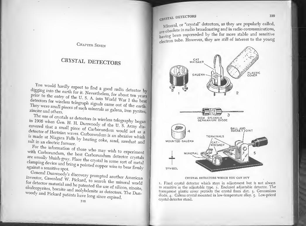
Chapter Seven
CRYSTAL DETECTORS
digging into the earth^Ht Neverthelfs *f deteCt°r by prior to the entry of the IT S a •® ’ for about ten years detectors for wireless A “ » World War I tie best
ml^wh^
IS made at Niagara Falls bv I '“"d™1■» an abrasive which
salt in an electS™' e. 7 g Sand’ Sawd“sl and
with CarborundumTheVe^rc*!!0 "'IT ™h *° e*Pe™<»t -e usually bluish-giavplZL £,7,™ ***'" c^tals clamping device and hrino- a . . / a ln some sort of metal
against a^nXe^pot ® P°m'ed C°Pper to •*» firmly
inventor, CreenleaMV ?n0tller American for detector material and he f , arch the mineral world
chalcopyrites, bo2tJdJf?T the "* °f silfc°". ^incite,
woody and Pickard patSnts have long ^ce ^ ^ ^
iTAL DETECTORS 119
ineral, or “crystal” detectors, as they are popularly called,
obsolete in radio broadcasting and in radio communications,
ng been superseded by the far more stable and sensitive
Ton tube. However, they are still of interest to the young
PLASTIC COVER GALENA
CRYSTAL DETECTORS WHICH YOU CAN BUY
i. Fixed crystal detector which stays in adjustment but is not always so sensitive as the adjustable type. 2. Enclosed adjustable detector. The transparent plastic cover protects the crystal from dirt. 3. Germanium diode. 4. Galena crystal mounted in low-temperature alloy. 5. Low-priced crystal detector stand.

120 THE BOYS’ FIRST BOOK OF RADIO AND ELECTRO]
experimenter-a ciystal is the simplest form of detector M
wZadio"1 “expensive and easy "V aoquajfc
There are a number of substances which can be used J crystal detectors. Some are natural minerals, others are tZS ?
of the electric furnace and chemical laboratory '"H
atom, a silvery appearing natural mineral composed of lead in combination with sulfur, is the most sensit”eTrysU
detector. Not every piece of galena will prove to be a Lj
radio detector. Furthermore, the whole surface of every pfeee
is not sensitive. There are small areas which are sensitive'll Aey can e located by placing the mineral
and at the same trme exploring the surface. Point the end of
a white chalk crayon and when a sensitive spot is found mark
it wrth the point of the chalk. Then split off most rffte Zd
tolocate aeai“ Cha°n!hat ““S f nS“ve sPot wi“ be difficult ,lJ, .rg °h k 1S used for ^ purpose because it will not destroy the sensitivity of the crystal add is easily seen
The most sensitive form of galena contains a small percentage
^anuTa^hmcf6" ga'“a’ rimes old to a Tm°n gn o' ArSmUfer°“ galena is some¬ times sold to amateurs under the name “steel” galena
Galenn and some other minerals perform best as detectors
a sman’shrZfZ^redded (with the sensitive area exposed) in 1] 0 a °y having a low melting temperature The
alloys used for this purpose (Wood’s metalTs one and it can
wato and even tf™ ? ChenliCal SUPPte> ™ boiling
of ^ radtofeW m°Unted Sakna CIyStak Ca" be Purchased from
Detector Stands. When a piece of mineral is used as a radio
elector it is usually clamped in a detector "stand.” The stand
chystai. detectors - “
adjustable contact point which can be made to touch
haS a° nf the upper surface of the mineral. Detector stands
any £ homemade On the other hand, the factory-made variety
ean be purchased at a low cost and usually has some advantages.
A HOLDER FOR UNMOUNTED CRYST/
MOUNTED CRYSTALS
7^\
■LJ
A CRYSTAL DETECTOR STAND WHICH YOU CAN MAKE
Detector stands intended for galena crystals are provided
with a fine wire spring called a “cat-whisker.” The point of the
whisker is brought into contact with a sensitive spot in the
galena and the pressure adjusted until the signals in the head¬
phones are loudest. The whisker on a homemade detector stand
should be a piece of No. 30 B. & S. gauge spring phosphor

122 the BOVS- hirst book of radio and electro,
bronze, brass or German silver wire r-„ , m
enough spring to make a satisfacto.y wh^gT 065 "0l S
mentrdXco™ :roHhdeeleCf0r T®"** * J If you hav^^1
conlams any specimens of the minerals’ listen 1*° ** * these minerals are detectors. ^ below. All of
COMMON NAME
Anatase
Bornite
Cerusite
Chalcocite
Chalcopyrites Copper Pyrites
. Domeykite
Calena
Hecsite
Iron Pyrites (Fools’ Gold) Molybdenite Niccolite
Octahedrite
Psilomelane Stibnite
Zincite
Zirconium
CHEMICAL NAME
Titanium dioxide
Copper-iron sulfide Lead carbonate
Copper sulfide
Copper-iron sulfide Copper sulfide
Copper arsenide Lead sulfide
Telluride of silver and gold Iron sulfide
Molybdenum sulfide Nickel arsenide
Titanium oxide
Manganese manganite Antimony sulfide Zinc oxide
Zirconium
ment The wMtVor^oSess^ext1 * ^ ,m°St ab™dant ele- quartz and sand is silica an V reme1^ hard constituent of
No one probably^ With "TO*
Swedish chemist, Jons Jacob RP i- 1COn Untl* tbe llIustrious fonn of a brown in the
take three forms: a dull-brown Q years ago. Silicon can
metallic scales resembling graphite ^a stS ,POWder- shin,nS -s. The crystalline
DISTAL DETECTORS m
bv heating silica with carbon in an electric furnace. It is
tl to alloy with iron to make special steels. uS® he steel-gray crystalline form of silicon makes an excellent
,. detector. It will not respond to far-away stations as well
13 galena but it will produce louder signals from near-by sta¬
tions The whisker used to make contact with a sensitive spot
on a piece of galena should be stiffer and bear against the spot
more firmly than the whisker used with galena. Iron Pyrites. The cubical crystals of this mineral are heavy
and of a brass-yellow color. A popular name for this combina¬
tion of iron and sulfur is “fools’ gold.” Many uninformed ex¬
plorers and prospectors have brought in a heavy load of iron
pyrites with the mistaken belief they had discovered gold.
HOMEMADE DETECTOR USING SILICON
OR IRON PYRITES
The spring contact should push against silicon and iron pyrites with greater pressure than is used with galena. Notice the difference in the shape of the spring contact in the illustration above and the shape of the whisker in the preceding illustration. They are designed so that the spring contact will have more pressure than the whisker.

ln,0 , , THE transistor 94s John Bardeen and W hr...
'es announced Hi,. • 7.“- t>rattain of the Hell tj l t a tiny wafer of , VCnhon of tbe transistor ?t,Te,tphJ0ne Labora :orm manv of the §ermanmm crystal with three ™ ^ lad discovered
>g sih?onyaSd othe" 10nS °f an Section tube wires ean rovements in rir. • f ma^er,als have also' been 7 f len transistors
device which was'bnsnt ?"struction accomplishcd°Th T’ many smallest vacuum f„l?8 , dcd In electronics It ifn, u transistor
S'Ssi'illss' ■ kMta' S fa«“" °f the., toL, li "and^^onJ
A
GERMANIUM diodes
d davicel^TgS™ Se^r3", I zjsszsiz:'rt ^ ™di~ by cC,: ssfss?*-»-
CBYSTAL DETECTORS 125
man chemist and he named his find Germanium in honor of
his fatherland. If you can afford a germanium diode it will prove to be far
more satisfactory than any other crystal detector you can build
or buy. It is sensitive, needs no adjustment and does not get
out of order unless mistreated. Never solder any wires or other
connections to the terminals of a germanium diode. The heat
of soldering may spoil it. Also, do not use it for any experiments
whereby more than a few thousandths of an ampere pass
through, or it may be burned out.
Silicon diodes in which the germanium is replaced by a small
piece of the element, silicon, are also manufactured. Ger¬
manium and silicon diodes are used in television receivers and
in microwave radio.

Chapter Eight
SIMPLE, PRACTICAL RADIO RECEIVERS AND HOW TO BUILD THEM
„ ^ •*"*”“* ™ong the nations of the world n quires all radio transmitters to be licensed. Under this aeree
men. a bansmitter is licensed for operation o,l, !S
9 y (or frequencies) assigned to it. Consequently it i
wt^s onlyof die ff ” ™E “ ‘ra"Smitto “ ‘hat it will produc "“ 7 of the frequency or frequencies assigned to the sta ton. Radio receivers must be adjusted or tuned to brine h
ignals properly. Tuning a receiver strengthens the desiredrig.
wttS^hTr.^ fr” ^ ™ £
J'SZtdST a"d a aeleplre receiver eeuueeted to an antenna and to the ground m the manner illustrated in the
diagram on this page will receive radio signals. A staple Z uned receiver such as this has a great drawback. It will re^e'
not receive simi^Y '""d”' Stat‘°n at *he same time and wiH
race v2 A med ?"* StaM°nS- “ * an m*m*i «*> STimpW t IT d°“ Ml haVe disadvantages.
or {he m3 effiYTf “ * 3 001 11 is ”°* best Fnr iK ? 55 f tumn§ apparatus but it is easy to make
bonk h "I635011 thC 6rSt tW° radio reivers described in this book employ tuning coils.
126
ANTENNA
AN UNTUNED RADIO RECEIVER
This simple receiver will bring in radio signals but its limited range and lack of tuning make it impractical. It will bring in signals from several
stations at the same time.
ANTENNA
CIRCUIT DIAGRAM OF A
SIMPLE TUNED RADIO RECEIVER
Some sort of tuning device is necessary to select desired signals and shut out unwanted ones. A tuning coil is the simplest form of tuner but not the most efficient one.

f“< Uz u2 2UUJ 2h <r' ozui u<x
WIT
H
CR
YS
TA
L
DE
TE
CT
OR
AN
D
SIN
CL
E-S
LID
ER
TU
NIN
G
CO
IL
SIMPLE, PRACTICAL RADIO RECEIVERS 129
HOW TO BUILD A RADIO RECEIVER
WITH CRYSTAL DETECTOR AND SINGLE-SLIDER TUNER
The simplest practical radio receiver which is worth the
time and effort to build consists of a single-slider tuning coil,,
a crystal detector, a fixed condenser and a telephone receiver.
Such a radio receiver costs little and does not require much time
to build. If you have never built radio apparatus, the experi¬
ence gained in building this receiver will be valuable in making
more elaborate instruments.
If there is a radio broadcasting station within 50 miles, you
can listen to its programs with this receiver. The sounds pro¬
duced in the headphones will not be loud unless you are within
a few miles of the station—but they will have amazingly clear
and natural tones.
Before starting the construction work, obtain all of the mate¬
rials in the following list. Consult the index for the page num¬
bers where mica condensers, crystal detectors, headphones and
magnet wires are described. Read about these parts before you
purchase them.
MATERIALS REQUIRED FOR
CONSTRUCTING THE RECEIVER
1 Wood base 7/s in. x 5 in. and from % in. to % in. thick
1 Wood block 2% in. x 23s in. x % in.
1 Wood core 4 in. x I% in. x 1% in.
130 ft. No. 26 B.S. gauge enameled magnet wire
1 Crystal detector
1 .004 Mfd mica fixed condenser
18 No. 5 round head brass wood screws K in. long
2 No. 5 round head wood screws 1 in. long
8 Brass or copper washers which will slip over No. 5 screws
1 Piece galvanized sheet iron approximately 2 in. x 4 in.
1 Piece No. 14 B. S. bare copper wire 2 in. long
1 Radio headset or a single telephone receiver wound for
radio use

130 THE BOYS’ FIRST BOOK OF RADIO AND ELECTRONR
Liquid shellac or varnish and brush
4 Binding posts or Fahnestock connectors
In addition to the materials listed above, materials to build
the coil winder described later in this chapter may be required.
The Base. Start by making the base. This can be made of
any variety of soft wood (except balsa) from X in. to % in. in
thickness provided it is seasoned and thoroughly dry. The end
of a wooden packing box is suitable lumber if it is thick enough.
Smooth rough spots by sandpapering and then give the whole
base-top, bottom and edges-a coat of shellac. Shellac dries
quickly. Apply a second coat when the first has dried. The
shellac will improve the appearance of the base but its main
purpose is to keep moisture out of the wood. Moisture in mate¬
rials used in the construction of radio apparatus may weaken
signals. The shellac also will help prevent the base from warp¬
ing. The wood must be thoroughly dry before the shellac is applied.
Caution: Do not use paint or enamel on the wooden parts of
radio apparatus. These finishes usually contain metallic sub¬
stances which may cause current leaks and even short circuits.
The wood block which supports one end of the slider should
he shellacked before it is fastened to the base.
The Tuning Coil. The core of the tuning coil is made of
pine or other soft wood and it also must be thoroughly dry. The
core is 4 in. long and 1% in. x 1% in. in section. (If a piece of soft
pine (not yellow pine) which is 1M in. thick cannot be obtained,
glue together two strips 4 in. x IX x % in. or three strips 4 in. x
lb in. x M in.) The edges are rounded slightly by sandpapering.
Drill a small hole M in. from each end so that the ends of a wire
can be anchored by looping through the holes. The holes should be near a comer.
If the core is to be wound in the homemade winding machine
bore a h in. diameter hole in each end exactly along the axis
of the core and one inch deep. You can find the exact spot to

m ■ m * | w ■ f
133 SIMPLE, practical radio receivers
The coil consists of a single layer of No. 26 B. & S. enamel
wire wound smoothly and tightly on the wooden core. The
winding starts and ends M inch from the end of the core and is
given a coat of shellac when completed. The shellac helps pre¬
vent the wire from becoming loose if the core shrinks slightly.
Before winding, the core should be dried for a few hours by
placing it on a warm radiator or in a warm oven (not hot). If
dried in an oven, the oven door should remain open. After the
core has been dried and while it is still warm, it should be
shellacked or varnished to prevent the wood from absorbing
moisture again.
The wire must be wound in a smooth, even layer. It is diffi¬
cult to wind a tuning coil without some sort of winding device.
Perhaps some one with a lathe-equipped home workshop will
wind a coil for you. Or perhaps you can do this yourself on a
lathe in the shop at your school.
If a metal turning lathe is used, one end of the wood core is
placed in a chuck on the headstock of the lathe. The other end
is supported on the center in the tailstock. The lathe should be
turned slowly by hand by pulling on the belt. If a wood-turning
lathe is used the wooden core for the tuner is mounted between
centers as if it were to be turned. Remember to turn the lathe
by hand. If you have not had experience winding coils, you will
not have much luck winding the coil with power. )
Those who are not fortunate enough to have a lathe available
should build a winding machine. This will not require much time.
The Slider and Other Metal Parts. The slider, the two
brackets which support the tuning coil and the small strip
labeled “connector” in one of the drawings are made of gal¬
vanized iron sheet. This is slightly thicker and stiffer than the
metal used in cans but you will not find it difficult to cut with
a small pair of tinner’s snips. You can obtain galvanized iron
sheet at a tinsmith’s or sheet metal working shop. It is inex-

the BOYS’ FIRST BOOK OF RADIO AND ELECTRONlcj
and2 toe.rglro^ * % fa- H
W T “d Ko’-oTu,"^ £?£ tiom) Drmtheth^P SUpP°rt the tuning coiI (see illustra-1
the locat" oittk^SV: 7* ‘he ““ M”k 1
holes with a No. 29 or No. 30 twto Ve^Td^
have sharp comers and edges, dull them with a file Se « ^
used for house wiring You CJ ‘et » , “* Com™"ly
makes contact with only one or two tumTat at£e St J° of metal sliding over the edce of ,t “7 ! ‘ slnP
contact with several turns at a ole . T'"\ 00,1 'V°uld make Tu n a ™ s at a tlme and weaken signals. The Condenser. The small fixed condenser should h o
he Detector. The illustrations show the receivpr^tn Ho
ZZt£L\germanium diode nient but any t^pe t^td ££ « »
- - - o-
Assembling and Wiring the Receiver. The wood block
WASHERS
FAHNESTOCK ^ CLIP
BATTERY THUMBNUT
HEX NUT
WOOD SCREWS
PLAN OF THE RECEIVER
WITH SINGLE-SLIDER TUNER
The dotted lines indicate the connecting wires. The terminals and bind¬ ing posts are lettered so that they can be identified with the corresponding binding posts and terminals in the schematic and pictorial circuit diagrams.
BINDING POSTS
i and 5 are inexpensive factory-made binding posts for fastening wires, 2, 3, and 4 show how you can make your own binding posts.
MACHINE SCREW
GROUND ANTENNA
PHONES ^WOOD BASE 7% x 5’

136 THE BOVS’ FIRST BOOK OF RADH> AND ELECTRON!
which supports one end of the slider is fastened to the base h„
two screws. The screws pass through the base from the unde^
side and upward into the block. r'
The tuning coil is mounted so that one comer is at the ton
Remove the enamel insulation from the wire along this com?
With apiece of fine sandpaper (No. 00) so that the bare coZ B exposed and the slider can make contact with it PP i
Wrap the free end of the slider with Scotch tape or adhesive
tape to form an insulating handle for the fingers. The tape will
prevent the fingers from touching the metal and mX
sIX C0”taCt W“h T°UChing ^ bare meta' Weake
The wires which connect the binding posts tuning
the ins°i I”"1 f°ndTer mn °Ver the t0p °f the base. Remove
at the nl 10n fI°m ‘ I6 6ndS °f the WirGS and scraPe bright at the places where they make an electrical contact. §
e pictorial diagram, schematic diagram and plan show
how to connect or “hook up” the parts of the receiver
binding post (A) to °ne end °f CcmJJ i l °ne terminaI of the condenser (C2). Connect the other terminal of the condenser (Cl) to one
“r ce dete?i (dik} and to °ne °f the ™ b-d^ rrr- u! °ther terminai °f the ***** (D2)
‘h p*er 7°.NE b,nd(ng p°st (P2), to the ground binding
an“ of Aa" ‘° “”neCl°r <C) ^
Operating the Receiver. Connect a telephone receiver or a
lo thet0 !he tPHONE binding P°sts- Connect an antenna O the ANTENNA bmdmg post and the ground to the ground
binding post The antenna should be a wire 50 to 75 feet long
and be insulated from its supports. The ground should be a wire
connected to a water, gas or steam pipe. Antennas and ground
connections are described in more detail in the chapter called
Antennas and Ground Connections.” P
After connecting the receiver to the aerial and ground, test
SIMPLE’ PRACTICAL RADIO RECEIVERS 137
i e detector to insure that it is in proper adjustment. If the
detector is a germanium diode, there is no need to test or
diust it. If the detector has an adjustable contact or whisker, it
should be tested so as to insure that the whisker or contact
wire rests on a sensitive spot on the crystal. To do this, a small
Tlie top diagram is schematic. The lower diagram is pictorial. These diagrams and the plan show how to hook-up the single slider-tuner
receiver.

THE BOYS’ FIRST BOOK OF RADIO AND ELECTRONli
hand drill for driv¬ ing SMALL TWIST DRILLS
SMALL TWIST DRILL FOR MAKING HOLES IN WOOD AND METAL
SNIPS FOR CUTTING SHEET METAL CENTER
PUNCH
MARK LOCATION OF HOLES IN SHEET METAL WITH A CENTER PUNCH BEFORE DRILLING
CUT METAL FOR SLIDERS BRACKETS ETC.,WITH SMALL SNIPS
TOOLS FOR MAKING THE METAL PARTS
OF THE RADIO RECEIVERS
buzzer, a dry cell, and a switch are required. The use of a test buzzer is explained at the end of this chapter.
When the sensitive spot on the crystal (where the sound of the buzzer is heard loudest) has been found, the receiver is in condition to bring in signals. Move the slider to the left or right until the signals from the station you have selected to listen to are loudest. When this place on the tuning coil has been found the No. 14 wire soldered to the bottom of the slider should rest on a single turn of wire on the coil and not touch two turns so that a short circuit is formed between them. WITH DOUBLE-SLIDER TUNING COIL
LOWER SLIDER
CONNECT PHONES HERE
ximiynrMAnp RADIO RECEIVER
simple, practical radio receivers
no not expect to hear many stations with this receiver and , ”ue surprised if you hear more than one at the same time.
tf the receiver is equipped with a detector having a whisker Ifr * contact, be careful not to jar it. It is easily knocked out of adjustment. When this happens, use the test buzzer to padiust the detector, or search the surface of the crystal, using
die signals from a broadcasting station to indicate when a
sensitive spot has been found. A single-slider tuning coil is not as efficient as a double¬
slider tuning coil or as a coupler. You can improve the operation of the receiver-it will be more selective, that is tune better and bring in more stations-if you build a wave trap and con¬ nect it as explained later in this chapter. A loading coil con¬ nected to the receiver will increase its frequency range and consequently may increase the number of stations you can
UPPER SLIDER
\ TUNING
COI \
MICA FIXED CONDENSER

“* THE BOTS' ™" «« O' HAD.O AND E,,ECra„N»
tuner into one with a double slider^OGF ^ * S“SIe-sIider
scratch” and build theTore XL ^ ^ Start fro* building the simpler one. receiver without first
itfanet^fo'r^r t,'° °”e Wilh * d°ubfe-slife. Strip and a new wood block The sM™ add!tional co™ectiJ
different in size from those wSfl, " and.W°°d “«* A and illustrated. It will be neress were Previousty described
because a differ,Zo£p ^ to ""*• *e receiver
^ sisttr^tmir rh dou“r*™J
"c;;:srse»”w^«K j 1 -004 Mfd. mica fixed condenser 4 binding posts
16 No. 5 round head brass wood screws X in. long
o. 5 round head wood screws 1 in. lone g
IZZeZ^ ™herS Which Wfll sliP over No. 5
1 Piece of galvanized sheet iron approximately 3 in x
SIMPLE’ PRACTICAL RADIO RECEIVERS 141
l Radio headset or a single telephone receiver wound for
radio use
X Telephone cord for radio receiver
The wood base, detector, condenser, binding posts, connect¬
ing strip and brackets which hold the tuning coil are the same
as those described for the receiver with a single-slider tuner.
The wood block is 2% in. x 2% in. x % in. Notice that it is }l in.
higher than the one used on the single-slider receiver.
Dry the base, wood block and tuning coil core and give
them a coat of shellac on all surfaces. The pine core for the tuning coil is 4% in. long and 1M in. x
1% in. in section. Wind it with a single layer of No. 26 B.S.
enameled magnet wire. Start and finish the winding % in. from

142 THE BOYS’ FIRST BOOK OF RADIO AND ELECTRON^
°f 1116 COm GiVe 1116 Wtadi"« ‘ “* of Mao wj
The brackets should be fastened to the ends nf
that when the cod is mounted on the base ! n * is X in. above the surface of the baset£JZ 'H
to provide room for the lower slider One slider It necessaiy
with Ae bo««„m the coil; the o^makes Z^lTS
top Remove the enamel insulation from the wire aW hot
the top and bottom corners of the coil by rubbing with No ml
Se“1116 - — « good
WITH SUNDlRS^0AEKEbSrCCOONlIACT
PLAN OF THE RECEIVER
WITH DOUBLE-SLIDER TUNER
The two wires which cross at the point marked “X” in -n * a- not electrically connected and h , n the illustration are
Consult the plan anTTtJ“£±g! 'nSoh“ f™> another, receiver. tic ^ia§ram when hooking up the
ANTENNA
ground
SIMPLE, PRACTICAL RADIO RECEIVERS 143
The two sliders are alike. Make each from a strip of gal¬
vanized iron sheet % in. wide and 4% in. long. Solder a straight
piece of No. 14 B. S. solid copper wire 3 in. long to each slider
as shown in the illustration. The wire stiffens the slider and is
the part which makes contact with the wire on the tuning coil
when the slider is moved to tune in a station.
The lower slider (marked S2 in plan) is pivoted on a round
head screw in the base. The side on which the No. 14 wire is
soldered is turned upward. The upper slider (SI) is pivoted on
a round head screw in the center of the wood block. This slider
(SI) is turned so that the No. 14 wire is on the underside. A
metal connecting strip (C) is placed under each slider between
the slider and the base. Use a washer under the head of both
screws. It may be necessary to bend both sliders slightly so
that they bear against the tuning coil with sufficient pressure
to make good electrical contact.
WRONG Mo. 14 wire
NO. 14 WIRE TOUCHES TWO WIRES ON COIL
RIGHT ^-Slider
NO. 14 WIRE RESTS ON ONE WIRE ONLY
SCHEMATIC CIRCUIT DIAGRAM
OF RECEIVER WITH DOUBLE-SLIDER TUNER
Signals will be louder when the slider rests on a single turn of wire than when it rests on two. See right-hand sketch.

144 THE BOYS’ FIRST BOOK OF RADIO AND ELECTRON**
Assembling and Connecting. The sketch of the finishJ receiver and the plan show better than words can how til various parts are assembled on the wood base. The plan anl
the circuit diagram show how the parts are connected. It »
essential to remove the insulation from the ends of all coJ
necting wires for a distance of % inch and to scrape the exposed copper bright and clean. |
Connect the antenna binding post (A) to one end of the
tuning coil (E). Connect the terminals of the detector (D and
Dl) to the phone binding posts (P and PI). Connect the
ground binding post to one of the condenser terminals (C2)
and to the connector (Cl) under the lower slider (S2). Con¬
nect the other terminal of the condenser (C3) to detector
terminal (D). Connect the other detector terminal (Dl) to
the connector (C) under the upper slider (SI). ‘ 1
Operating the Receiver. Connect a telephone receiver or a
radio headset to the phone binding posts. Connect an antenna
to the antenna binding post and the ground to the ground
binding post. Test the detector to insure that it is in proper
adjustment. Move the sliders (one at a time) until you find
the position on the tuning coil where they bring in loudest the signals to which you wish to listen.
HOW TO BUILD A RADIO RECEIVER
WITH A CRYSTAL DETECTOR AND A COUPLER
The device called a coupler makes a better tuner than a
tuning coil. A coupler consists of two coils. One coil contains
more turns of wire than the other and is called the primary. The
primary is connected to the aerial and ground. It is tuned with
a slider. The secondary contains fewer turns of wire and is con¬
nected to the detector. It is tuned with a variable condenser.
There is no direct electrical connection between the primary
and secondary. They form a transformer. High frequency cur¬
rents in the primary induce high frequency currents in the
sImple, PRACTICAL radio receivers 145
NG COIL COUPLER
, SLIDER TUNING CONDENSER
FIXED CONDENSER
DETECTOR llllllllllllllllllllllllllllllllllllllllllllli
RADIO RECEIVER TUNED BY A COUPLER
AND VARIABLE CONDENSER
This is the best of the three receivers described in this chapter. It has
greater range and better tuning than the others.
secondary by the process called electromagnetic induction.
Couplers were very popular with amateur wireless experi¬
menters who used crystal detectors in the early days of radio.
The instrument they used was called a “loose coupler. The
secondary coil of the loose coupler could be moved in and out
of the primary coil, in fact moved several inches away from
it when necessary. This adjustment was called varying the
coupling and aided in tuning the receiver. Loose couplers were
usually purchased ready made or built from factory made parts
which were available at that time. Such parts are not manu¬
factured today. For that reason and also because it is the pur¬
pose of this book to describe only the simplest radio apparatus,
the coupler described here is “fixed.” The coupling or space
between the primary and secondary cannot be varied. The
receiver could be tuned better if the coupling was variable but
variable coupling would make construction of the receiver
difficult for a beginner at building radio apparatus.

146 THE BOYS’ FIRST BOOK OF RADIO AND ELECTRO]
LIST OF MATERIALS H
Reqwreo to build a radio receiver
WITH A CRYSTAL DETECTOR AND A COUPLER
1 Wood base 10% in. x 5 in. x % in.
* ^16Ce °f white Pine in- x 18 in. x 132 in.
20? B> S‘ gaUge enameled magnet wire •t'04 Mid. mica condenser
1 150 or 250 mmfd. single gang variable condenser i Knob lor variable condenser
1 Crystal detector
4 Fahnestock connectors or binding posts
18 No. 5 round head brass screws J£ in. long
2 No. 5 round head brass screws 1 in long
“rfttd“ne screws *ia Io”g t0 fil b°fe
20 Brass or copper washers to slip over No. 5 wood screws l Piece galvanized iron sheet 3 in. by 4 in.
Construction. Dry the base and wood block and give them a
coat of shellac. The base is 10% in. x 5 in. x % in. The ZoTbhol
MaWL™6 "'I USCd f°r the singIe*sbder tuning coil
iTstouHebe°5e/0r t ^ °Ut0f White Pine’ When finished, t should be 5/4 in. long and 13* in. by 1X in. in section. Round
the comers slightly with sandpaper. After drying give the core
n°f„fteaC- The V"' tlohS b0red * -Sal™ wh™ m ! "e ^ the * to- doweI rods »hich are used
marked A B^C 'Tn^ T ‘j® homemade winder. The holes
uSdin^ lhC *"*« ** ‘-e
Wind the secondary first. It consists of 50 turns of No 26
holesTaTd r We W°Und 2 Si”g,e Sm°°th ^ The small ends of the with the larger hole D and the
Wh“ A Se°°ndary W1"dmg are led out through these holes
of fttT h“ 17 “ been WOand w™P one or two layers of thin tough paper around it. Then wind the primary This
SIMPLE. PRACTICAL RADIO RECEIVERS
ingle layer of No. 26 B. S. enameled wire which starts at
I,3opposite end of the core from the secondary and ends when *t has overlapped the secondary about % in. This end of the
1 rimary is the terminal (E) which is connected to the antenna
binding post (A). Do not make a mistake and connect the
other end of the primary to (A) or the receiver will not operate
satisfactorily. The coupler is mounted on the forward left hand
comer of the base, supported by two brackets made of sheet
metal. One bracket should be the same size and shape as those
used to support the single-slider tuner, the other is a straight
Vq dia. hole
I 5/8 DEEP
HOLE FOR DOWEL
50 TURNS NO.26 ENAMELED WIRE
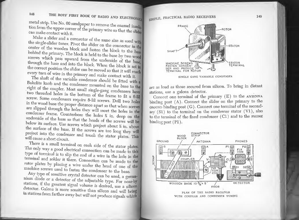
the boys* first book of radio and electronics
tiOT W?rt,USe N°‘ 00 SandPaPer t0 rernove the enamel fasuh me upper comer of the primary wire so that the slidJ
can make contact with it. 1 der
Make a slider and a connector of the same size as used wil
the smgle-shder tuner. Pivot the slider on the connector in if
center of the wooden block and fasten the block to the b3
behind the primary. The block is held to the base by two woJ
screws which pass upward from the underside of the basJ
through the base and into the block. When the block is set J the correct position the slider can be moved so that it will re J
The hT ^ and make -^act Jth it BaSV^ u Vt.ariabIe condenser should be fitted with a Sof^1 condenser counted on the base to the
tw^^fd^T ^.^ ral1 sin£Ie~§anS condensers have
s^eJ Snm r “ tt0m °f the frame t0 fit a 6-32 screw. Some condensers require 8-32 screws. Drill two holes
in the wood base the proper distance apart so that when screws
are slipped through the holes they will meet the holes fa the
condenser frame. Counterbore the holes M in deep on the
belowi^s /he n86 S° ^ the heads °f the scre™ ^ be the i fraCv ULSe Screws which Proiect about % in. above the surface of the base. If the screws are too long they will
project into the condenser and touch the stator plates.7 This will cause a short circuit. * ■
Thehnn7 “ & SmaU °" Cach Side °f ^ Stator P^es. tvne ^ a,g°°d el?Cilical ^nection can be made to this
te^in erm;ni7 t0 S uP thC end °f a Wire in the hoIe in the Ofar nl TV r * Connection can be made to the
rotor plates by placing a wire under the head of one of the
machine screws used to fasten the condenser to the base. |
nf, °f S6njltlVe Crystal dctector can be used, a germa- mum diode or a detector of the adjustable type. For near-by
statmns, if the greatest signal volume is desired, use a silicon
detector. Galena is more sensitive than silicon and will bring
°nS fr°m farther away but will not produce signals which
PRACTICAL RADIO RECEIVERS
FRAME
ROTOR
STATOR
SHAFT-
STATOR TERMINAL
MACHINE SCREWS FASTEN CONOEN- SER AND PROVIDE TERMINAL FOR ROTOR
SINGLE GANG VARIABLE CONDENSER
are as loud as those secured from silicon. To bring in distant
stations, use a galena detector. Connect one terminal of the primary (E) to the antenna
binding post (A). Connect the slider on the primary to the
ground binding post (G). Connect one terminal of the second¬
ary (SI) to the terminal on the condenser stator (VI), also
to the terminal of the fixed condenser (Cl) and to the phone
binding post (PI).
CONNECTOR STRIP WOOD
BLOCK
GROUND PHONES ANTENNA
WOODEN BASE I03a"x 5 KNOB
PLAN OF THE RADIO RECEIVER
WITH COUPLER AND CONDENSER TUNING

150 THE BOYS' FIRST BOOK OF RADIO AND ELECTRONICS |
Connect the other terminal of the secondary (S2) to the
condenser rotor and also to the detector terminal (Dl). Con
nect the other terminal of the detector (D2) to the terminal of
the fixed condenser (C2) and also to the phone binding post (P2). 8
SCHEMATIC CIRCUIT DIAGRAM FOR
HOOKING UP THE COUPLER AND VARIABLE CONDENSER
SIMPLE, PRACTICAL RADIO RECEIVERS 151
To operate the receiver, connect the antenna post (A) to
n antenna and the ground post (G) to the ground. Connect
a radio headset to the phone posts (PI and P2). Adjust the
detector and use both the slider and the variable condenser to
tune. Turn the variable condenser slowly. The frequency range of the receiver can be increased by con¬
necting a loading coil and wave-trap to it.
HOW TO BUILD A LOADING COIL AND WAVE TRAP
Neither of the tuning coils described in this chapter are long
enough to tune in signals over the entire band of frequencies
used by American broadcasting stations. It would be difficult
for most students to construct the type of slider that is re¬
quired for longer tuning coils. The problem can be solved by
a loading coil, or better still by a loading coil and wave trap. A
loading coil is simply a single-slider tuning coil which is con¬
nected in series with the antenna and the radio receiver. The
loading coil and wave trap combination is a single-slider tuning
coil and a variable condenser mounted on a wooden base. This
also is connected in series with the antenna and radio receiver.
ground .antenna
PHONES
.004 MFD. FIXED CON.
ANTENNA API SECONDARY I VARIABLE COIL COIL CONDENSER
DETECTOR
PICTORIAL DIAGRAM FOR HOOKING UP
THE COUPLER AND VARIABLE CONDENSER
MATERIALS REQUIRED
FOR CONSTRUCTING A LOADING COIL
1 Wood base 7& in. x 4 in. x % in.
‘ 1 Wood block 2% in. x 2M in. x % in.
125 ft. No. 24 B.S. gauge enameled magnet wire
1 Piece of galvanized sheet iron approximately 4 in. x 2 in.
1 Piece No. 14 B. S. bare copper wire 2 in. long
3 Fahnestock connectors or binding posts
11 No. 5 round head brass screws % in. long
2 No. 5 round head brass screws 1 in. long
4 Brass or copper washers to slip over No. 5 wood screws
The parts used in building the loading coil are the same
parts used in building the single-slider tuner. The base is

152 the boys’ fikst book of badio and electoon«J
a LOADING COIL
Sie"fWK?ne °f th‘S instrument » “antenna loading coil When connected in the antenna circuit of an? of the receivers described in this chapter it is d07
nn eh° tULne ln SignaIs of lower frequency thaJ is possible when it is not used. 4 y an Is
slightly smaller than the one used for the receiver Cut thp
strips used m making the slider, brackets and connector from
g yanize n-on sheet to the dimensions shown in the illustra tion of ^ Slngle.slider tuner So]der the 2 ,nch
a e copper wire to one side of the slider. Wrap the end of the
shder which has no hole in it with Scotch ta^e or adhere
tape to provide an insulated handle for the fingers to touch
wZdAeb and ^ Sh°Uld be dried and backed. 1 md the tuning coil core with a single layer of No 24 B S enameled wire. Start and finish the winding7 about % in from he ends of the core. Use a piece of No. 00 sandpaper to remove
r?r,rom th,e ~ loZTZ The plan t male a ®°°d contact, the plan shows how the parts are assembled on the base
The co I 1S supported by the two metal brackets. One endTf
tothebase1bvtwoeN°nK 6 ".T* b'°Ck' 71,6 b,ocfc is fastened
** s *
SIMPLE’ PRACTICAL RADIO RECEIVERS 155
0ne terminal of the coil (E) is connected to binding post
/Rl Binding post (A) is connected to the slider.
The loading coil can be used with all of the receivers with
stal detectors. Disconnect the antenna from the antenna
binding post on the receiver and connect the antenna to the
ajJtenna binding post (A) on the loading coil. Connect bind¬
ing post (B) on the loading coil to the antenna binding post
on the receiver. To tune in a station move the shder on the loading coil and.
the slider on the receiver to the positions where the signals
desired come in the loudest. To convert the loading coil info a combination loading coil
and wave trap, it is only necessary to connect the terminals of
a midget single gang variable condenser to binding posts (A)
and (B) on the loading coil. These small condensers cost
very little to buy. They are made in eight sizes or capacities
ranging from 15 micromicrofarads (abbreviated mmfd) to 450
ANTENNA RECEIVER
PLAN OF THE LOADING COIL

154 THE BOYS’ FIRST BOOK OF RADIO AND ELECTRON^
micromicrofaracls^ Any of the sizes from 100 mmfd to 450
can be used for the wave trap. The condenser should be with a Bakehte knob to fit the M in. shaft. d
One terminal of the variable condenser is the frame of IB
condenser. The other terminal is either one of the two smJ
lugs at the sides of the condenser. Connect a wire to one of thf
!ugs by soldering. Connect a wire to the frame by placing the
end of the wire under the head of one of the screws which hdd the condenser frame to the wood base.
CIRCUITS OF LOADING COIL AND WAVE-TRAP
,^'7,“ Sh0W! h0W t0 a ““g “il or . wave-trap
PRACTICAL RADIO RECEIVERS
SECONDARY
OIA. HOLE
50 TURNS NO. 26 BS ENAMELED WIRE
PRIMARY
PRIMARY OVERLAPS SECONDARY 3/glNCH
THE COUPLER
It is advisable to make a unit of the coil and condenser by
mounting them on the same base. Use a wooden base about
8 in. x 4 in. x % in. Dry the base and shellac it before using. The
condenser is fastened to the base by two machine screws which
pass upward through the base and into the threaded holes in
the bottom of the condenser. The screws should be just long
enough to thread into the condenser without projecting. If the
screws are long enough to go through the base of the condenser
and touch the stator plates, they will short circuit the condenser
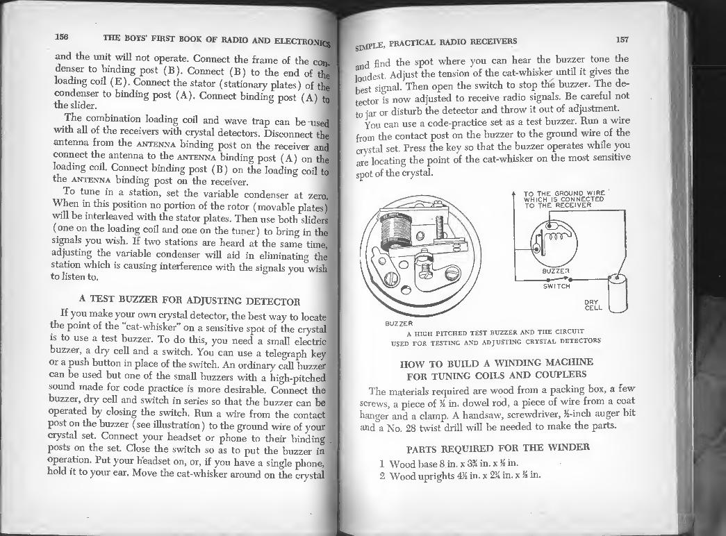
156 THE BOYS’ FIRST BOOK OF RADIO AND ELECTRONICS
and the unit will not operate. Connect the frame of the con
denser to binding post (B). Connect (B) to the end of the
loading coil (E). Connect the stator (stationary plates) of the
condenser to binding post (A). Connect binding post (A) to the slider. ^
The combination loading coil and wave trap can be used with all of the receivers with crystal detectors. Disconnect the
antenna from the antenna binding post on the receiver and
connect the antenna to the antenna binding post (A) on the
loading coil. Connect binding post (B) on the loading coil to the antenna binding post on the receiver.
To tune in a station, set the variable condenser at zero.
When in this position no portion of the rotor (movable plates)
will be interleaved with the stator plates. Then use both sliders
(one on the loading coil and one on the tuner) to bring in the
signals you wish. If two stations are heard at the same time,
adjusting the variable condenser will aid in eliminating the
station which is causing interference with the signals you wish to listen to.
A TEST BUZZER FOR ADJUSTING DETECTOR
If you make your own crystal detector, the best way to locate
the point of the “cat-whisker” on a sensitive spot of the crystal ;
is to use a test buzzer. To do this, you need a small electric i
buzzer, a dry cell and a switch. You can use a telegraph key
or a push button in place of the switch. An ordinary call buzzer j
can be used but one of the small buzzers with a high-pitched
sound made for code practice is more desirable. Connect the
buzzer, dry cell and switch in series so that the buzzer can be
operated by closing the switch. Run a wire from the contact
post on the buzzer (see illustration) to the ground wire of your
crystal set. Connect your headset or phone to their binding
posts on the set. Close the switch so as to put the buzzer in
operation. Put your headset on, or, if you have a single phone,
hold it to your ear. Move the cat-whisker around on the crystal
SIMPLE, PRACTICAL RADIO RECEIVERS 157
nd find the spot where you can hear the buzzer tone the
loudest. Adjust the tension of the cat-whisker until it gives the
best signal. Then open the switch to stop the buzzer. The de¬
tector is now adjusted to receive radio signals. Be careful not
to jar or disturb the detector and throw it out of adjustment.
You can use a code-practice set as a test buzzer. Run a wire
from the contact post on the buzzer to the ground wire of the
crystal set. Press the key so that the buzzer operates while you
are locating the point of the cat-whisker on the most sensitive
spot of the crystal.
BUZZER
A HIGH PITCHED TEST BUZZER AND THE CIRCUIT
USED FOR TESTING AND ADJUSTING CRYSTAL DETECTORS
HOW TO BUILD A WINDING MACHINE
FOR TUNING COILS AND COUPLERS
The materials required are wood from a packing box, a few
screws, a piece of % in. dowel rod, a piece of wire from a coat
hanger and a clamp. A handsaw, screwdriver, &-inch auger bit
and a No. 28 twist drill will be needed to make the parts.
PARTS REQUIRED FOR THE WINDER
1 Wood base 8 in. x 3% in. x K in.
2 Wood uprights 4M in. x 2U in. x /i in.

158 THE BOYS’ FIRST BOOK OF RADIO AND ELECTRONICS
2 Wood battens 3M in. x VA in. x % in.
2 Pieces M-in. dia. maple dowel 3 in. long
1 Piece of steel wire from a coat hanger
8 No. 6 round head wood screws 1J1 in. long
Cut the wooden parts to the dimensions shown in the illus¬
tration. Dry them and shellac them. Bore a M-in. diameter hole
through both uprights on their center line and 3% in. from an end.
Make two holes in each upright with a No. 28 twist drill.
The holes should be % in. from the end and at the end opposite
the h in. hole. Slip a No. 6 wood screw through each of the
small holes in the uprights and fasten each upright to a batten.
Fasten each batten to the base using two screws which pass
upward through the base from the underside. Use the No. 28
holes to drill through the base for the screws. Countersink the
heads of the screws. The battens should be located so that the
SIMPLE’ PRACTICAL RADIO RECEIVERS 159
distance between the uprights is % in. longer than the core
which is to be wound. The % in. diameter hole in the uprights
are bearings and must be in line so that a piece of % in. diameter
dowel passing through both holes will turn freely. Fasten one
upright and batten to the base. Then slip the dowel through
the bearing holes in both uprights and fasten the second batten
to the base at the proper distance. Assembling the winder with
the dowel shaft in the bearing holes will bring the holes into
line. A piece of steel wire (from a coat hanger) is slipped through
a hole near the end of one of the dowels and bent to form a
crank. This wire handle is used to turn the core when winding
it. The dowel shafts should turn freely in the bearing holes in
the uprights. If they are hard to turn, free them by sandpaper¬
ing the dowels to make them slightly smaller.
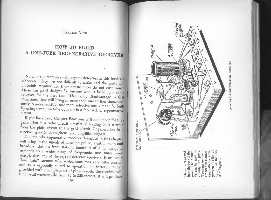
Chapter Nine
HOW TO BUILD A ONE-TUBE REGENERATIVE RECEIVER
m
n None of the receivers with crystal detectors in this book are
elaborate. They are not difficult to make and the parts and
materials required for their construction do not cost much.
These are good designs for anyone who is building a radio
receiver for the first time. Their only disadvantage is that
sometimes they will bring in more than one station simultane¬
ously. A more sensitive and more selective receiver can be built
by using a vacuum tube detector in a feedback or regenerative circuit. °
If you have read Chapter Four you will remember that re¬
generation m a radio circuit consists of feeding back current '
from the plate circuit to the grid circuit. Regeneration in a
receiver greatly strengthens and amplifies signals.
The one-tube regenerative receiver described in this chapter
will bring in the signals of amateur, police, aviation, ship and
broadcast stations from stations hundreds of miles away. It
responds to a wider range of frequencies and tunes morel
sharply than any of the crystal detector receivers. It utilizes a
ow drain vacuum tube which consumes very little current
and so is especially suited to operation on batteries. When!
provided with a complete set of plug-in coils, the receiver will ]
tune in all wavelengths from 16 to 550 meters. It will produce J
160
yw W" w\vT\y y'wWv
regenerati
ve receiv
er

162 THE BOYS’ FIRST BOOK OF RADIO AND ELECTRON^
loud signals in a pair of headphones but does not have enou<*
signal strength to operate a loudspeaker unless connected to f amplifier. u
A one-tube receiver is the best model for a beginner tM circuit is less complicated than that of a receiver using mor!
an one tube and there is less chance of making a mistake in e wiring The parts are less expensive and can be assembled
more easily. You do not actually “build” a receiver of this
ype. You cannot make satisfactory variable capacitors, volume
controls, etc. They must be factory made. The only homemade
parts are the wood base, panel, ground plate, connecting strips
and a wooden bolster. The other parts can be purchased from a
dealer m general radio supplies. Such firms advertise in the
radio magazines and are glad to send you their catalog if you
write them for it. The necessary screws can be obtained at a
hardware store. Here is a list of the parts and materials needed:
ONE-TUBE REGENERATIVE RECEIVER
The receiver from the front of the panel. This view reveals parts which cannot be seen in the preceding sketch. ^
HOW TO BUILD A ONE-TUBE REGENERATIVE RECEIVER 163
1 6BF6 Receiving tube (22)
1 Wood base 7% in. x 6% in. x % in. (2)
1 Wood panel 7Js in. x 4M in. x % in. (3)
1 Piece of wood 1 in. x 2M in. x M in. to be used as a
bolster for the variable capacitor “ if necessary
5 Connecting strips 1M in. x % in. cut from thin sheet metal
1 Piece of thin sheet metal 7M in. x 5£ in. 1 500,000-ohm volume control (8)
1 Switch to fit volume control (9)
1 Knob for volume control (10)
1 Vernier knob and dial (6) 2 4-prong plug-in coils for broadcast band when used with
a 365-MMFD tuning capacitor
1 10 to 365-MMFD variable tuning capacitor
1 4-prong socket (77)
1 Socket for 7-pin 6BF6 tube (12) .2 4-80 MMFD-mica trimmer capacitors (7) 1 2.5-millihenry radio frequency choke (16)
1 2.2-megohm % watt resistor (15)
1 .0001-MFD mica capacitor (14)
1 .0025-MFD mica capacitor (13)
1 6-volt battery or 6.3-volt filament transformer
1 67)2- or 90-volt B battery 8 Binding posts or Fahnestock connectors (17)
1 Single-terminal Bakelite terminal strip (19) 1 Three-terminal Bakelite terminal strip (20)
14 %-in. No. 6 round head brass wood screws
4 M-in. 6-32 round head brass machine screws with brass
nuts to fit 2 %-in. 6-32 round head brass machine screws
1 2000-ohm radio headset
4 Rubber head tacks; 8 Small tacks
Shellac, sandpaper, rosin-core solder, push-back wire
4 Round head screws and spacers for mounting sockets
* Let’s call condensers by their accurate scientific name from now on.
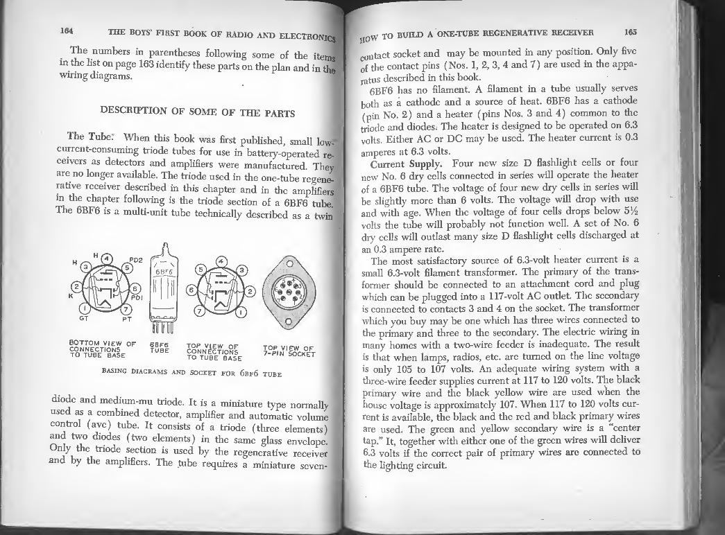
164 THE BOYS’ FIRST BOOK OF RADIO AND ELECTRONICS I
• ^he numbers in parentheses following some of the items
in the list on page 163 identify these parts on the plan and in the
wiring diagrams.
DESCRIPTION OF SOME OF THE PARTS
The Tube. When this book was first published, small lowJ
current-consuming triode tubes for use in battery-operated re¬
ceivers as detectors and amplifiers were manufactured. They
aie no longer available. The triode used in the one-tube regene¬
rative receiver described in this chapter and in the amplifiers
m the chapter following is the triode section of a 6BF6 tube
The 6BF6 is a multi-unit tube technically described as a twin
BASING DIAGRAMS AND SOCKET FOR 6bf6 TUBE
diode and medium-mu triode. It is a miniature type normally
used as a combined detector, amplifier and automatic volume
control (avc) tube. It consists of a triode (three elements)
and two diodes (two elements) in the same glass envelope.
Only the triode section is used by the regenerative receiver
and by the amplifiers. The tube requires a miniature seven-
jj0W TO BUILD A ONE-TUBE REGENERATIVE RECEIVER 165
contact socket and may be mounted in any position. Only five
of the contact pins (Nos. 1, 2, 3, 4 and 7) are used in the appa¬
ratus described in this book. 6BF6 has no filament. A filament in a tube usually serves
both as a cathode and a source of heat. 6BF6 has a cathode
(pin No. 2) and a heater (pins Nos. 3 and 4) common to the
triode and diodes. The heater is designed to be operated on 6.3
volts. Either AC or DC may be used. The heater current is 0.3
amperes at 6.3 volts. Current Supply. Four new size D flashlight cells or four
new No. 6 dry cells connected in series will operate the heater
of a 6BF6 tube. The voltage of four new dry cells in series will
be slightly more than 6 volts. The voltage will drop with use
and with age. When the voltage of four cells drops below 5%
volts the tube will probably not function well. A set of No. 6
dry cells will outlast many size D flashlight cells discharged at
an 0.3 ampere rate. The most satisfactory source of 6.3-volt heater current is a
small 6.3-volt filament transformer. The primary of the trans¬
former should be connected to an attachment cord and plug
which can be plugged into a 117-volt AC outlet. The secondary
is connected to contacts 3 and 4 on the socket. The transformer
which you buy may be one which has three wires connected to
the primary and three to the secondary. The electric wiring in
many homes with a two-wire feeder is inadequate. The result
is that when lamps, radios, etc. are turned on the line voltage
is only 105 to 107 volts. An adequate wiring system with a
three-wire feeder supplies current at 117 to 120 volts. The black
primary wire and the black yellow wire are used when the
house voltage is approximately 107. When 117 to 120 volts cur¬
rent is available, the black and the red and black primary wires
are used. The green and yellow secondary wire is a “center
tap.” It, together with either one of the green wires will deliver
6.3 volts if the correct pair of primary wires are connected to
the fighting circuit.

166 THE BOYS’ FIRST BOOK OF RADIO AND ELECTRON!) 167
PLUG
TO 117 VOLT OUTLET
.-GREEN
GREEN-YELLOW 6-3 VOLTS
BLACK-YELLOW
6.3-VOLT FILAMENT TRANSFORMER
SECONDARY TERMINALS
Sockets. Eby one-piece molded Bakelite sockets for the tube
and coil can be mounted more easily than other types. They
can be fastened, directly to the wood base with two screws.
Amphenol MIP” sockets and Eby wafer sockets made of lami¬
nated Bakelite cost less than other sockets. They can be used
if mounted on spacers which raise them about % inch above the base.
The Volume and Regeneration Control. This should be the
type to which a switch can be attached. Purchase a switch also.
The switch is connected in series with the tube filament and
the battery which heats the filament. Then the same knob
which controls the volume and regeneration can be used to turn the receiver on and off.
Variable Capacitor. Purchase a standard midget single gang
TRF type variable capacitor with two bearings. It is more
rugged than a single bearing capacitor. The maximum capacity
should be 365 micromicrofarads (abbreviated MMFD) and
the minimum when the plates are not intermeshed about 10
MMFD. TRF is the abbreviation for “tuned radio frequency.”
H0W TO BUILD A ONE-TUBE REGENERATIVE RECEIVER
There is space for trimmers provided on the TRF capacitors
trimmers are not used at that point in the circuit of a
regenerative receiver. Small rotary variable capacitors are
usually so built that the capacity increases when the shaft is
turned in a counterclockwise direction. The shaft can be ro¬
tated 180°. Capacitors are sometimes listed in catalogs as condensers.
Capacitor is a better term and is gradually replacing the older
word. The Dial and Knob. Any of several types of knobs which fit
a li-inch round shaft can be used to turn tire variable capacitor.
Some are equipped with pointers designed to swing over a
dial plate attached to the panel. Others have a dial which
moves with the knob and a marker on the panel indicates the
position of the dial. It is difficult to make a close adjustment
of the variable capacitor with any of these direct drives. A
Turn this knob to move dial
VERNIER DIAL BAKELITE KNOB AND DIAL
TUNING DIALS AND KNOBS
The knob and dial at the right is a direct drive device. Any rotation of the knob moves the tuning capacitor an equal amount. The vernier knob and dial is an indirect drive. The knob and dial are geared to the capacitor so that the knob must be turned a considerable distance in order to turn the capacitor a short distance.

168 THE BOYS’ FIRST BOOK OF RADIO AND ELECTRONICS
vernier dial is more satisfactory. It should have a 0-180°
counterclockwise scale to fit the capacitor. The knob on a'
vernier dial does not drive the condenser shaft directly. It
geared. The knob on the type of vernier dial in the illustration
must be tinned several revolutions in order to turn the con¬
denser shaft one-half revolution. This permits very fine adjust¬ ment of the condenser and close tuning.
Trimmer Capacitors. Trimmer and padder capacitors are
commonly used in radio receivers to adjust circuits which in¬
clude radio frequency transformers and variable capacitors. In
the one-tube regenerative receiver, two trimmer capacitors
connected in parallel are used to tune the antenna circuit. They
are adjusted with a screwdriver. It is necessary to use a dif¬ ferent adjustment for each plug-in coil.
A small variable capacitor which has a capacity range of
10 to 200 micromicrofarads can be used in place of the two
trimmer capacitors. It is easier to adjust (adjustment is made
by turning a knob) than trimmer capacitors but costs five
times as much as a pair of trimmer capacitors. Trimmer ca¬
pacitors are used in the one-tube regenerative receiver to keep the cost low.
The Plug-in Coils. It is advisable to purchase factory made
plug-in coils for the receiver. Several mail order firms sell
completed coils and also unwound coil forms. 4-prong, 5-prong ?
and 6-prong coils are available but only 4-prong coils will fit
this one-tube regenerative receiver. Each 4-prong plug-in coil
consists of two separate windings wound on a molded Bakelite
form. The terminals of the windings are connected to the
prongs. The prongs fit the standard 4-prong tube socket. The
upper (and longer) winding is called the antenna and grid
coil. The lower and smaller winding is the “tickler” coil.
The size of the coils plugged into the 4-prong socket deter- ;
mines the frequency range of the receiver. You will need two
readymade 4-prong plug-in coils with proper windings so that
when used with a 365-MMFD tuning condenser, the frequency \

170 THE BOYS’ FIRST BOOK OF RADIO AND ELECTRONICS
band of the receiver will cover the broadcast band. Coils cov¬
ering the higher frequencies or shorter wavelengths are also obtainable.
Some radio parts can be scarce and it can be difficult to
find readymade plug-in coils,for example. It may be necessary
then to buy empty coil forms and wind them. The method of
winding is described later in this chapter.
The Homemade Parts. The base of the receiver is a piece
of pine 7/8 in. x 6/8 in. x % in. Smooth it with sandpaper and
finish all surfaces including the underside with two coats of
white shellac. The shellac will seal the wood against moisture
Bod reduce its tendency to warp. The panel is a piece of ply-
PARTS FOR THE RECEIVER
Two connecting strips are used to connect the trimmer condensers in parallel. Three of the connecting strips are used as terminals. Use one under each of the nuts on the back of the panel which hold the phone
posts, and one to make connection to the frame of the tuning capacitor. The two sockets at the lower left are Eby sockets. The letter “T” indicates the terminals on the high-frequency choke.
the panel
The panel is made of *4 in. to Vs in plywood, drilled‘ as ^X'Lnd top drawing. The drawing at the bottom shows the front ot the pane after the parts have been mounted on it. The position of the ho s
drilled in the panel and used to mount theX ^^holdd“iSted from the locations shown in the upper sketch. They should be located
to fit the particular capacitors and dial which you use.

172 THE BOYS’ FIRST BOOK OF RADIO AND ELECTRO]
wood measuring TO in. x M in. The thickness is unimportj
Plywood ganging from % in. to % in. thick will make a satisW
tory panel The panel should be shellacked on both sides
roundT’d h hstGne<\ t0 0ne ed§e of the base by three No^ round head brass wood screws (marked S in illustration). '9
The ground plate is a piece of thin sheet metal (galvanized
mm or tinplate) 7M in. x 51 in. It can be cut out of aone-g^
to ?! °fuSDipS- Cut 3 SmaU Piece 0ff each corned so as to elunmate the sharp points. Flatten the metal by pounding it
in each °f 1°^ and then Punch ei§ht sma11 boles, one
edge midway from the c°4 The ground plate is fastened to the underside of the base bv
eight small tacks which pass through the holes punched in it
with a nail. If the receiver is equipped with the type of variable
capacitor which must be fastened to the base, the ground plate
cannot be attached to the base until after the capacitorP has
been mounted. If a panel-mounted capacitor is used the
ground plate can be attached before the panel is put in place.
The ground plate reduces “body effect.” This is a disturbance
m the tuning which may take place when a hand is moved either toward or away from the receiver.
If a panel-mounting variable capacitor is used, it will not
be necessary to make a small wood bolster. This in. x I in
x /4 in. wood strip is required only for a base-mounting variable
amrt as°I-h e h°hteT sh°uId be the same distance apart as the mounting holes in the condenser so they will align.
ASSEMBLING THE RECEIVER
™7Ian °f *b® receiver in one of the illustrations is the best guide for assembling the parts on the base and panel. At the
°P 15 a SCaIe f.°r use [n determining the exact location of the parts. This scale can be used to measure inches in the same
INCHES
trimmer capac. 2- 4-80MMFD-
365 MMFD. ^ VAR. CAP.
.OOOl Mm
PLAN
vdFarln,er jm
i ii n
rfa fa w ©
□ D 0 □ a □

174 THE BOYS’ FIRST BOOK OF RADIO AND ELECTRoJ
The Fahnestock Connectors (17) or binding ™ . -
mounted near the baek edge of the base so that wifes W ?'
ba terles, ete, ean be attaehed to them without disturbing ' ' ot the receiver wiring. n§
The Radio-Frequency Choke (16) is held to the base h !
TtS nreW °h passes through a hole in the center of?/ choke. Do not use an iron screw. f
The Resistor (15) is not fastened down to the base It • upported by its own terminal wires.
The Mica Fixed Capacitors (14) and fill am d ported by their own terminal wL ind
Variable Capacitor. The variable capacitor (5) in the model
“i c r : rSis fr- fte £5 beutT0rled Tthepane1' The Shaft "hm™(
the bottom of "th ^ ^ maC^ne screws pass upward from
tact with the ground plate. The screws should not be long
“S KCf' 5,rOUgVhe CapadlOT f-me mor^ S ctuTL":;:’,”?ti,ey w'M iouch *he—f- Short
PaneUf v^l! CaPaoilors are designed to be mounted on a
to make a Lt “ Capacitor °{that '»»’ X™ will not need to make a bolster strip. Bore a hole in the panel just large
ough to pass the threaded bearing. Push the bearing through
on theb fr0m t?6 °f tHe Pand and place the threaded nut
“rt p„uaednI™7 'he fr07 *• “> ‘he oapaci- tor is pulled firmly against the rear of the panel.
JJOVV TO BUILD A ONE-TUBE REGENERATIVE RECEIVER 175
To Mount a Vernier Knob and Dial. Screws, nuts and a
er mounting template are packed with each vernier dial of
the type shown in the illustrations. y Place the mounting template on the panel so that its center
coincides with the center of the variable capacitor shaft.
2 Use a sharp scriber or a prick punch to mark all hole cen¬
ters through the template onto the panel. 3. Remove the template and drill the holes of the diameter
specified on the template. 4. If the capacitor shaft projects more than % inch beyond
the front of the panel cut the surplus length off with a hacksaw.
5. Remove the hub cap from the dial by pulling it out.
6. Slip the dial over the end of the capacitor shaft that projects
through the panel and fasten it in place by means of the four
small screws, lock washers and nuts furnished with the dial.
7. Set the capacitor at its zero or position of minimum ca¬
pacity and rotate the dial until it also is at zero before tighten¬
ing the set-screw. 8. Tighten the hub set-screw but when doing this make certain
that the dial disk is pushed back far enough so that it does not
rub against the inside of the dial casing.
CLEAR LUGS AND SCREW ON BACK
TRIMMER CAPACITORS
Holes must be drilled in the panel and the terminals on the trimmer capacitors must be bent as shown in the illustration before the capacitors
can be mounted.

176 THE BOYS' FIRST BOOK OF RADIO AND ELECTRONICS
9. Replace the hub cap by pushing it into place.
The drive ratio of the vernier dial is variable. It provides 6 to 1 gearing in the fast position and 20 to 1 gearing in t3
slow position. Intermediate ratios can be selected by pr0nP,
positioning of the small metal ball directly above the tunL knob. 8
How to Attach the Switch to the Volume Control. Pry off
the removable portion of the metal cover on the volume control
Hold the control in your left hand so that the shaft points
toward you. Use your right hand to turn the shaft in a clock¬ wise direction as far as it will go.
IqVY TO BUILD A ONE-TUBE REGENERATIVE RECEIVER 177
Notice that there are two projecting metal tabs or ears
the metal rim of the switch—also that there is an opening in
°l switch cover. Inside the switch and visible through the
nening is a “V”-shaped cam. Moving the cam operates the
witch .Move the cam until it is in the center of the opening.
Line up the projecting ears on the switch housing with the
^etal guides in the control case. Then press the switch firmly
against the control and while holding it in that position bend
the ears so that the switch cannot slip away from the control.
The control is mounted on the back of the wood panel with
the shaft projecting from the front of the panel. Drill a hole
in the panel just large enough so that the shaft bushing will
pass through. Slip the bushing into the hole from the back of
the panel and put the nut on from the front. Tighten the nut
until the control is held firmly against the panel. Before tight¬
ening the nut turn the control so that the terminals are at the
The shaft provided on the control will probably prove to be
longer than is necessary and it must be cut off so that the
control knob will be close to the panel. If the shaft is the
notched type, it can be shortened by holding it m a pair ot
pliers and breaking it at the notch which will reduce it to the
correct length. If the shaft is not notched, cut off the surplus
length with a fine tooth hacksaw. Fasten a molded Bakelite knob of the set screw type to the
control shaft. Slip the “U”-shaped adapter which comes with
the control over the end of the shaft. Loosen the set screw m
the knob until it will not prevent the knob from sliding on the
shaft. Set the knob where it belongs and tighten the set screw
with a small screwdriver.
WIRING THE RECEIVER
When all parts have been fastened in position on the panel
and base, the receiver is ready for wiring. Use push-back wire
for the connections. The ends of all wires except those which

178 THE BOYS’ FIRST BOOK OF RADIO AND ELECTRONICS
can be clamped firmly under a screw or nut should be soldered
with rosin core solder only. Acid core solder may cause shJ
circuits which will prevent the receiver from operating. Instmc
tionm soldermg is found in another chapter at the end of tj£
, Jh® schemati^ circuit diagram, pictorial circuit diagram and plan show how to make the connections. Have a pencil
“ each ccnnection is made, make a check mark alongside the equivalent connection on the circuit diagrams
a d plan. Check each connection in this manner and it will
help to insure that none are overlooked. The wires should be
as^short as possible Some wires in the plan are sho™ W
than is necessary from the standpoint of good wiring. They
were drawn dial way so that each wire can be traced from
one end to the other. Follow the circuit diagrams and the plan
with the utmost care. After completing the wiring, check it
SCHEMATIC CIRCUIT DIAGRAM
FOR THE ONE-TUBE REGENERATIVE RECEIVER
179 oW TO BUILD A ONE-TUBE REGENERATIVE RECEIVER
carefully the second time. If a single wire is omitted or con¬
nected to the wrong place the receiver will not operate. The
black wires in the plan are filament circuit connections.
HOW TO OPERATE THE RECEIVER
When the wiring is complete and has been checked, the
receiver is ready for use. Connect a 2,000-ohm radio headset to the phone terminals
on the front of the panel. Place a type 6BF6 tube in the tube
socket (12) and a 4-prong broadcast coil in the 4-prong socket
(11). Mark the wooden base near each terminal so that the
terminals can be readily identified as in the plan. Connect an
antenna to the ANT terminal and a ground wire to the GND
terminal.
PICTORIAL CIRCUIT DIAGRAM
FOR THE ONE-TUBE REGENERATIVE RECEIVER
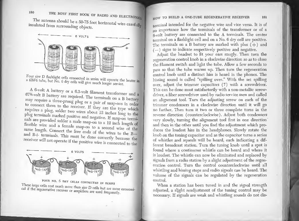
180 THE BOYS’ FIRST BOOK t
The antenna should be a 50-75 ft
insulated from surrounding objects
electron^
wire carefulh.
6 VOLTS
Four size D flashlight cells a 6BF6 tube, but No. 6
A 6-volt A battery
6714-volt B battery
may require a three-i
to connect them to the
in series will operate the heater in Is WlH gJve much longer service. 1
or a 6.3-volt filament transformer and a
equired. The terminals on a B battery
or a pair of snap-ons in order
If they are the type which wires about 12 inches long to the
positive and negative. If snap-on termi-
—i snap-on to a 12 inch length of
snap-on to a second wire of the
ree ends of the wires to the B—
iSt be done correctly because the
e positive wire is connected to the
are r<
prong plug
—i receiver. requires a plug, solder two
plug terminals marked p - ■ -
nals are provided solder a male
flexible wire and a female
same length. Connect the j
and B-f terminals. This mi
receiver will not operate if tl
6 VOLTS
four NO. 6 DRY CELLS CONNECTED
•ells cost much more than size D cells enerative receiver or amplifiers are us
|*8 ij M tA J
i*4*f*c
5
& Lsizg i
M:
HOW TO BUILD A ONE-TUBE REGENERATIVE RECEIVER 181
terminal intended for the negative wire and vice versa. It is of
no importance how the terminals of the transformer or of a
6-volt battery are connected to the A terminals. The center
terminal on a flashlight cell and on a No. 6 dry cell are positive.
The terminals on a B battery are marked with plus ( + ) and
(—) signs to indicate respectively positive and negative. Adjust the headset to fit your ears snugly. Then turn the
regeneration control knob in a clockwise direction so as to close
the filament switch and light the tube. Allow a few seconds to
pass so that the tube warms up. Then turn the regeneration
control knob until a distinct hiss is heard in the phones. The
hissing sound is called “spilling over.” With the set spilling
over, adjust the trimmer capacitors (7) with a screwdriver.
This can be done most satisfactorily with a non-metallic screw¬
driver, a fiber screwdriver used by radio service men and called
an alignment tool. Turn the adjusting screw on each of the
trimmer condensers in a clockwise direction until it will go
no farther. Then turn it two or three complete turns in the
reverse direction (counterclockwise). Adjust both condensers
very slowly, turning the alignment tool first in one direction
and then in the other until you find the adjustment which pro¬
duces the loudest hiss in the headphones. Slowly rotate the
knob on the tuning capacitor and as the capacitor turns a series
of whistles and squeals will be heard, each indicating a dif¬
ferent broadcast station. Turn the tuning knob until a spot is
found where a continuous whistle can be heard and where it
is loudest. The whistle can now be eliminated and replaced by
signals from a radio station by a slight adjustment of the regen¬
eration control. Turn the control counterclockwise until all
whistling and hissing stops and radio signals can be heard. The
volume of the signals can be regulated by the regeneration
control.
When a station has been tuned in and the signal strength
adjusted, a sljght readjustment of the tuning control may be
necessary. If signals are weak and whistling sounds do not dis-
18! THE BOVS’ FIRST BOOK OF RADIO AND ELECTRONIC,
appear when the regeneration control is turned back almost1
trimmer capadtors!^ ^ «£
When you have learned how to tune in stations in the broad
cast band, you may wish to listen to stations on other frequen
cies pohce, amateur, ship-to-shore, etc. Remove the broadcast
band C01l fr°m the 4-prong socket and replace it with a coil
intended for the frequencies you are interested in. The trimmer
condensers must be adjusted for each coil. The adjustment of
e trimmers need not be close, except for weak signals. Weak
signals require careful and close adjustment of all three con¬
trols, namely; the tuning capacitor, the trimmer capacitors and
the regeneration control. Careful tuning is required to bring
taZ ^ amate”Stf0nS’ THe fre(iUency of an amateu? station is always much higher than that of a broadcast station.
mateur stations operate on much lower power than broadcast
stations and their signals must be built up by careful adjust-
thereiVer COntr°k * requireS SOme exPerience and skill to tune the receiver so as to secure its best performance. So
don t expect to pick up stations all over the world the first time you have the set in operation.
Signals from broadcasting and amateur radiotelephone sta-
ions come m best when the regeneration control is adjusted
just below the point where whistling is produced. Telegraph
signals ( dits and dahs ) from code stations come in best when
the regeneration control is adjusted just above the point where whistling is produced. r
TROUBLE SHOOTING
Suppose that you have completed your receiver, hooked it
up according to directions but do not pick up any signals. What
then. You will have to go trouble shooting and find the cause.
There are several things to do which may locate the trouble.
1. Disconnect the headphones from the phone post and touch
HOW TO BUILD A ONE-TUBE REGENERATIVE RECEIVER 183
the terminals of the phone cord to the terminals of the filament
, A) battery. If you do not hear a click each time you make and
break the circuit, there is a loose or broken connection in the
phone cord or in the receivers. 2 Turn the volume control switch so that the tube heater
is lighted. Disconnect the positive B battery wire from the B+
binding post on the receiver. Tap the bare end of the wire
against the B+ post and listen in the headphones. If you do
not hear distinct clicks in the headphones, there is a connection
missing or broken. Look for it. If clicks can be heard in the headphones when you discon¬
nect the B battery, it is a good omen and you can proceed to
test other parts of the receiver. If no whistles or squeals are heard in the headphones when
a broadcast coil is in the coil socket and the tuning control and
regeneration control are moved back and forth (as far as they
will go), the receiver is not regenerating.
1. The trimmer capacitors may be set up too tight to permit
the receiver to regenerate. Loosen the adjusting screws on both
capacitors and try tuning the receiver again.
2. If the receiver will not regenerate and produce squealing
and whistling sounds when the controls are moved, check all
connections and also check the batteries. Both A and B batteries
should be fresh and connected properly.
3. Examine the variable tuning capacitor. Check it carefully.
Make certain that there is no dirt, a small piece of wire or metal
between the plates and short circuiting the rotor and stator.
4. Failure to regenerate may be caused by a tickler coil wind¬
ing which is reversed. It is then necessary to reverse the con¬
nections which lead from the regeneration control to the coil
socket. Unsolder the wires connected to the socket terminals
marked T and C in the plan and solder to T the wire formerly
connected to C. The wire formerly attached to T should be
soldered to C. Do not make this change, however, until it is

184 THE BOYS’ FIRST BOOK OF RADIO AND ELECTRONICS
certain that failure of the receiver to regenerate is not due to other causes.
HOW TO WIND A PLUG-IN COIL
Smooth and ribbed molded Bakelite coil forms of several
lengths and diameters are listed in radio catalogs. To make the
coils for the one-tube regenerative receiver which will enable
it to tune in the broadcasting frequencies, buy two 4-prong,
smooth rim coil forms, either 134 inches or IX inches in diameter
and with a winding space 2X inches long. About 75 feet of
No. 34 B.S. gauge enameled wire and 35 feet of No. 30 B.S.
gauge are also required. A /4-lb. spool of each size is the smallest quantity sold and is more than sufficient.
COILS FOR THE BROADCAST BAND
The forms must be drilled so that the ends of the windings can pass through to the prongs. The left-hand sketches show the distance of the holes from the bottom of the forms. The holes can be spaced farther apart around the circumference of the form so that each is above its cor¬ responding prong. The holes and corresponding prongs are marked with the same numerals in the illustration.
HOW TO BUILD A ONE-TUBE REGENERATIVE RECEIVER 185
Four holes to anchor the ends of the windings must be drilled
through the side of each form. The location of the holes is indi¬
cated in one of the illustrations. Bore the holes with a No. 52
twist drill held in a drill press or hand drill. The drill may have
a tendency to slip away from the spot where a hole is to be
made. This difficulty can be avoided by marking the spots
where the holes are to be drilled and making a small indenta¬
tion at each of these spots with the point of a penknife. Twist
the knife blade until the point makes an indentation in the
Bakelite form deep enough so that when the point of the drill
is placed in it, the drill will not slip or “walk” away. When all four holes have been drilled, turn the coil form so
that the prongs point toward you and the two large prongs are
at the bottom. Mark the prongs 1,2, 3,4, starting with the upper
right hand small prong and proceeding in a clockwise direction.
Use the point of a penknife blade to scratch the numerals on
the base close to the prongs exactly as shown in the illustration.
Notice that the upper left hand prong (one of the small ones)
is No. 1; the lower left hand prong (large) is marked 2, etc. It
is necessary for these numbers to correspond with those in the
illustration or the circuit will be incorrect and the receiver
will not operate. Wind 150 turns of No. 34 on the grid coil (upper winding)
and 45 turns on the tickler coil (lower winding). Use No. 30
B. S. enamel for coil B. Wind 70 turns on the grid coil (upper
winding) and 20 turns on the tickler coil (lower winding).
Wind all the coils in the direction indicated by the arrow in
the illustration.

187
Chapter Ten
YOU CAN BUILD AN AMPLIFIER
Lee De Forest soon discovered that his audion tube was not
only a good detector for wireless telegraph signals—it was also
a wonderful amplifier of amperes and volts. A tiny, almost im¬
measurably small current fed to the grid of the tube would
cause a much greater current to flow in the plate circuit. In this
way a few electrons could control a great procession of other
electrons. At first the amplifier was used principally to intensify
wireless telegraph signals. Weak signals, hardly audible in the
headphones, could be intensified and heard several feet away
from the phones. Next it became a telephone “repeater.” Before
1914 the longest distance it was practical to telephone was
about 1,000 miles. The tiny electrical impulses carrying the
voice over telephone wires were lost in travelling the distance
from New York to Denver unless the copper wires were one-
half inch in diameter. Some practical method of boosting and
amplifying the feeble currents was necessary to make trans¬
continental telephony possible. The American Telephone and
Telegraph Company bought the audion patent from De Forest
for $50,000.00. The scientists and engineers of the Bell labora¬
tories soon found how to improve the tube and use it as a tele¬
phone amplifier (called a “repeater” when used in telephony).
Telephony across the continent was made a comparatively
186
Y0U CAN BUILD AN AMPLIFIER
simple matter. Today it is possible to talk between any two
nlaces where wires can be stretched. Vacuum tube amplifiers
L a necessary part of the present telephone system. On a
coast to coast call, the currents controlled by your voice pass
through thousands of tubes. The vacuum tube amplifier proved to be one of the most im¬
portant inventions of the twentieth century. It is an essential
part of all radio, radar and television transmitters and receivers,
of the telephone system and of almost unnumbered laboratory
AN ELECTRONIC AMPLIFIER
The amplifier is one of the most useful inventions of the past century. It is an essential part of modem radio, radar and television receivers and
or,a is nf crrpat value in manv sciences.
AN AMPLIFIER WILL IMPROVE THE PERFORMANCE
OF ANY OF THE RECEIVERS DESCRIBED IN THIS BOOK
A detector alone will not operate a loudspeaker. The power
to operate the speaker in a broadcast receiver is secured by
sending the signals from the detector into an amplifier. An
amplifier called a radio-frequency amplifier strengthens the
radio frequency currents before they reach the detector. T e
amplifier which strengthens the signals after they pass through
the detector is an audio-frequency amplifier. It is not easy for the beginner at radio to make a radio-

188 THE BOYS’ FIRST BOOK OF RADIO AND ELECTRONICS
frequency amplifier but, fortunately, it is not difficult to build simple audio-frequency amplifiers. The construction of two audio-frequency amplifiers is described in this chapter. Either one, added to any of the crystal detector receivers or to the one-tube receiver, will greatly increase the strength of the signals heard in the headphones and sometimes will operate a small speaker. r
An amplifier which employs one tube is called a single-stage amplifier. An amplifier which feeds the amplified current from one tube into a second tube is a two-stage amplifier. Each tube and its circuit is a stage. Amplifiers of many stages are often used in electronics.
HOW TO BUILD A ONE-STAGE AUDIO AMPLIFIER
The parts required to build the one-tube amplifier are:
1 Wood base, 6 x 4% x % inches 1 6BF6 receiving tube 1 Audio input transformer 3 to 1 ratio 1 100,000-ohm, K-watt resistor 1 7-pin miniature tube socket
7 Connectors or binding posts, whichever you prefer Hook-up wire and solder
2 No. 5 round head brass screws %-inch long 7 Screws for fastening the connectors or binding posts 2 Screws and spacers for fastening the socket
Shellac and brush
The tools required are a screwdriver, cutting pliers, soldering iron, ruler, pencil, a hand drill if you use binding posts and
AebalT WO°dWOrking t0°ls may be necessary.to cut out
The first step is to make the base from a piece of smooth, dry
wood Dry is emphasized because current will leak and weaken signals it a piece of damp or unseasoned wood is used The base should measure about 6 x 4% x % inches but it is not neces-

190 THE BOYS’ FIRST BOOK OF RADIO AND ELECTRON^
sary to make it exactly these dimensions. It can be M in l
instead of * tad, thick. Wood thinner than this wffl ,1‘i warp more readily. Smooth the top and edges by sandpapeS
necessary. Then give all surfaces two coats of shellac The shellac will seal the wood.
f16 JeIIac is dry> the Parts can be mounted on the •\ e. Fasten the two input terminals or posts at the left hand
side of the base and the transformer to their right. The two
input posts are used to connect the amplifier to a receiver.
is advisable to solder all wiring and connections. Satisfac-
toiy connections to a vacuum tube socket are difficult to make
without soldering Use rosin core solder and push-back wire
You can identify the primary and secondary terminal wires
on a standard transformer by the color of their insulating cover-
IRON CORE
PRIMARY AND SECONDARY WINDINGS
SYMBOL
TERMINALS
AUDIO TRANSFORMER
Sails' The hrdfed types an,d SiZCS 0f transformers are listed in radio described as a ‘‘low n?>T .in buildlng the , one-stage amplifier is aescriDea as a low-priced audio-interstage transformer for sinele nlate to
si ei"*E‘Bo" »r A for a ““■S'-
ordered for you from a wholesaler. The price should not be'more than
a Inzl/ m JOv sno''"' hl?h'I>rl“d milage translormeui available but ign quality transformer is not required for this amplifier.
YOU CAN BUILD AN AMPLIFIER 15,1
mg. The primary wires are blue and red; the secondary wires
are green and black. The wires may be coated with wax or
paraffin and the colors faint and difficult to read. In that case
the colors can be made clearly visible by applying a warm (not
hot) soldering iron on the insulation for an instant. Connect
the blue primary wire to one of the input posts and the red
primary wire to the other. Set two No. 5 round head brass
screws %-inch long into the wood base to the right of the trans¬
former and U2 inches apart. Solder the green secondary wire
(this is also called the grid wire) to the head of one of the
screws. Solder the black secondary wire to the head of the
other screw. Twist the end of one of the wire terminals on a 100,000 ohm,
52 watt resistor around one of the screws and solder it in place.
Twist the end of the resistor’s other terminal around the second
screw and solder it. This will connect the resistor directly across
the secondary of the transformer. The tube socket should be
fastened to the base at the right of the resistor. Connect the
brass screw (x) to which the green secondary or green wire is
soldered to the grid terminal (No. 1) on the tube socket. Solder
the connection between the wire and the socket. •
The output terminals or posts on the amplifier are those to
which the phones or loud speaker are connected when the
amplifier is in operation. They are located at the right and front
of the base. The battery posts are located along the rear edge
of the base toward the right-hand end. Mark these posts from
left to right B—, A, A and B+ as shown in several of the illus¬
trations. Black pencil marks on the wood base alongside each
terminal will suffice. One of the terminals marked A is con¬
nected to contact No. 3 on the socket. The other A terminal is
connected to the No. 4 socket terminal. The negative terminal
of the B battery is connected to the B— terminal on the ampli¬
fier. A wire connected to the B— terminal on the amplifier
should also be connected to the No. 2 (cathode) socket termi¬
nal and to the brass screw (Z) to which the black secondary
wire from the transformer is connected. A wire attached to one

192 THE BOYS’ FIRST BOOK OF RADIO AND ELECTRONICS
SCHEMATIC Connect batteries here
Connect to phones or speaker
PICTORIAL AND SCHEMATIC CIRCUIT
DIAGRAMS OF THE ONE-STAGE AMPLIFIER
y0U CAN BUILD AN AMPLIFIER 193
PLAN OF ONE-STAGE
TRANSFORMER-COUPLED AUDIO-AMPLIFIER
phone or output terminal should be connected to No. 7 (plate)
terminal on the socket. The other phone terminal post is con¬
nected to the B+ terminal post. If you consult both the pictorial and schematic diagrams you
should not have difficulty in wiring the amplifier correctly. As
in all radio work, use only rosin-core solder for soldering. A
67^-volt B battery and a 6-volt source of heater current are
required to operate the amplifier. A 6-volt dry battery, a 6-volt
storage battery, or a 6.3-volt AC supply from a filament trans¬
former can be used to supply heater current. The two wires supplying heater current should be connected to binding post
terminals A and A. Use a 6BF6 tube and a 6TA- or 90-volt B
battery. Connect the positive pole of the B battery to the B+

194 THE BOYS’ FIRST BOOK OF RADIO AND ELECTRONICS
post and the negative pole to the B— post. Put the 6BPft tube in the socket and push it down as far as it will go. It j
necessary for the positive and negative poles of the B battery to be connected to the proper posts or the amplifier will nZ operate.
The diagrams show how to connect the batteries to the am¬ plifier and how to connect the amplifier to a crystal receiver and to the one-tube regenerative receiver described in the last chapter. In order for the diagrams to be simple, details of the
receivers and amplifier are not shown. They show only the
DOUBLE-SLIDER RECEIVER ONE-STAGE AMPLIFIER
HOW TO CONNECT THE ONE-STAGE AMPLIFIER
TO A CRYSTAL RECEIVER
The diagram above shows how to connect the double-slider receiver to the one-stage amplifier. The phone posts on the receiver are connected
to the input posts on the amplifier and the phones are shifted to the
output posts on the amplifier. Any of the receivers with a crystal detec¬ tor can be connected to the amplifier in the same manner. The batteries
play no part in the operation of the crystal detector, their energy is utilized solely by the amplifier. 57
95
PHONES
REGENERATIVE RECEIVER ONE-STAGE AMPLIFIER
HOW TO CONNECT THE AMPLIFIER
TO THE ONE-TUBE REGENERATIVE RECEIVER
The PHONES posts on the receiver are connected to the'NPUT posts on
the amplifier A pair of phones or a small loudspeaker (4 to 5 inch) are
connected to the^iutput^iosts of the amplifier. use the same B battery and the same source of A current. The switc
on the volume control on the receiver turns the heater current on and off
in the receiver only. It does not control the heater current in *e amplifier
tube. When the apparatus is not in use a wire should be dBcounected
from an A terminal post on both the receiver and the amplifier to pre
vent waste of current.
bases of the instruments and the terminal posts. Diagrams of
this type are the “block” diagrams used often in radio books
The amplifier does not require any tuning or adjustment,
is not provided with an “on-off” switch and in order to preserve
the batteries, they should always be disconnected when the
amplifier is not in use.

196 THE BOYS’ FIRST BOOK OF RADIO AND ELECTRONICS
When strong signals come in through a receiver, the amplj.
fier will increase their strength sufficiently so that a small loud',
speaker of the permanent magnet type can be used in place of
the headphones. The speaker (4 or 5-inch) must be one pro¬
vided with a matching transformer. In this arrangement, the
secondary of the matching transformer is connected to the
voice coil in the speaker and the primary terminals of the trans¬
former are connected to the output posts of the amplifier in
place of the headphones. Speakers can be purchased equipped
with a matching transformer already connected to the voice coil.
TWO-STAGE RESISTANCE-COUPLED AMPLIFIER
HOW TO BUILD A TWO-STAGE AMPLIFIER
Nowadays, the audio-frequency amplifiers built into broad¬
cast receivers do not usually employ audio-frequency trans¬
formers. They use resistance coupling in place of transformer
coupling. The amplifier described above is a resistance-coupled amnlifier.
f0U CAN BUDLD AN AMPLIFIER
For the sake of simplicity and to make the two-stage ampli-
r eaSy for the radio beginner to build, the tnode sections o
tw0 multi-unit tubes are used. This is simpler than using
^TtefoUowing part^ and materials are used in building the
two-stage amplifier:
1 Wood base 8% x 4£ x % inches
2 6BF6 radio tubes 2 7-pin miniature sockets
3 .01 Mfd, 400-volt paper capacitors
2 100,000-ohm, M-watt resistors
5 2-terminal Bakelite terminal strips
5 Screws for mounting terminals 4 Screws and spacers for mounting sockets
8 Fahnestock connectors and mounting screws
PLAN OF THE RESISTANCE-COUPLED AMPLIFIER

198 THE BOYS’ FIRST BOOK OF RADIO AND ELECTRONlCs
2 500,000-ohm, lA watt resistors
8 Connectors or binding posts
4 Screws for fastening the sockets
8 Screws for fastening the connectors or binding posts Hookup wire and solder
Shellac and brush
The tools required are a screwdriver, cutting pliers, soldering
iron, ruler, pencil, a hand drill if you use binding posts and
whatever woodworking tools may be necessary to make the DaS0.
The base should be thoroughly dry and all of its surfaces
given two coats of shellac varnish. The plan of the amplifier
w lich is illustrated shows how the parts are arranged on the base.
Eight terminal posts are provided for connecting the am¬
plifier to a receiver, batteries, phones, speaker, etc. The current
SCHEMATIC CIRCUIT DIAGRAM
OF THE TWO-STAGE RESISTANCE-COUPLED AMPLIFIER
This diagram and the plan will enable you to wire the amplifier.
f0U CAN BUILD AN AMPLIFIER
bich is to be amplified is led in through the input posts. The
Strengthened or amplified current goes to the headphones or
sneaker through the output posts. can identify the 100,000-ohm resistors from those harmg
_ resistance of 500,000 ohms by their color bands. The 100,000
ohm resistors have a brown band, a black band and a yellow
band- the 500,000-ohm resistors have a green band, a black band
Id a yellow band. There should be a fourth band on the resis¬
tors and it may be either gold or silver. As explained earlier
in the book, the gold and silver fourth bands indicate the accu-
“cy of the’ band markings. A silver band on a lOO.OO^ohm
resistor indicates that its resistance may actually be from 90,000
to 110,000 ohms instead of 100,000 and a gold band indicates
double-slider receiver two-stage amplifier
HOW TO CONNECT THE TWO-STAGE AMPLIFIER
TO A RECEIVER WITH CRYSTAL DETECTOR

200 THE BOYS’ FIRST BOOK OF RADIO AND ELECTRONICS
that the resistance may be 95,000 or 105,000 ohms. If there i,
no fourth band the resistance may be 80,000 to 120,000 ohms
For building this amplifier choose resistors which have silver
fourth bands. They are accurate enough for the amplifier and cost less than resistors with gold fourth bands.
fnl? Sh°^ld n,0t be diffi^ult to ™ ^e amplifier correctly if you
trated ^ uP^ Schematic diagram which are ilhis-
Sd Lt UT uTe,Cti°nS t0 the SOGketS> condensers and g im. * ' Use Push"hack wire and resin core solder.
When the wiring is completed, connect a 1.5-volt, type D
flashlight cell to the A battery posts (marked A and A) Con
nec, a 67K- or 90-volt B ba.,er/,„ the' B battety po^maS
regenerative receiver PHONES
two-stage amplifier
HOW TO CONNECT THE TWO-STAGE AMPLIFIER
TO THE ONE-TUBE REGENERATIVE RECEIVER
YOU CAN BUILD AN AMPLIFIER 201
B+ and B—). Place a 6BF6 tube in each socket and the ampli¬
fier is ready to operate. Connect the output posts of a crystal detector receiver or
the one tube receiver to the input posts on the amplifier. Con¬
nect a pair of phones to the output posts on the amplifier. No
tuning or adjustment of the amplifier is necessary. If you have
wired it correctly, if the component parts are in good condition,
it will operate when supplied with proper current. Disconnect
the A battery when the amplifier is not in use.
AN INTERESTING EXPERIMENT WITH AN AMPLIFIER
If you build the one-tube amplifier you can use it to demon¬
strate how a vacuum tube is used to strengthen the feeble cur¬
rents which carry telephone messages to distant points. Until
1915 the telephones of the Bell System consisted essentially of a
call bell, a transmitter, a receiver, an induction coil and a
battery. By means of switchboards located in central offices, a
telephone could be connected to any other telephone desired.
With this equipment it was impractical to talk over telephone
lines more than 1000 miles long. Then the special form of am¬
plifier called a “repeater” was added to the telephone system,
making long distance telephony possible between any places
where wires can be stretched, no matter how far.
In order to demonstrate the action of your amplifier in
strengthening currents which produce speech and sounds, a
microphone is needed. A microphone is an apparatus for chang¬
ing faint sounds into variations in an electric current. When
sounds strike a microphone, an electric current flowing through
the microphone is changed in strength in rhythm with the
vibrations of the sounds. There are many varieties of micro¬
phones. A telephone transmitter is a form of microphone called
a carbon microphone.
Microphones were invented originally to improve the opera¬
tion of Bell’s first telephones. The first Bell telephones which
were installed for commercial service were clumsy and ineffi-

202 THE BOYS’ FIRST BOOK OF RADIO AND ELECTRONICS
cient instruments with little resemblance to the telephones of
today. Messages were shouted into a curious affair which looked like a wooden potato masher. Then, in order to hear the faint
answer, the “potato masher” was held to the ear. The original
Bell telephones had no battery and no separate transmitter—
the same device served both as transmitter and receiver.
The telephone could not have come into wide use without a
practical transmitter. A transmitter made it possible to use a
battery. A battery furnishes much stronger currents than those
which were generated by Bell’s “potato masher.”
The telephone transmitter in use today was developed over
the years from inventions made by Thomas A. Edison, Emil
Berliner, Professor David E. Hughes, Francis Balke, Henry
Hunnings and an expert of the Bell Company named White.
One of the most valuable bits of knowledge used in the
design of telephone transmitters was discovered by Professor
Hughes. He demonstrated that a loose contact between the
electrodes of a transmitter produced better results than a firm
strong contact. The simple apparatus which Hughes devised to
show this principle was the first microphone. He placed a small
iron nail across two other nails which were part of a circuit
containing a battery and a telephone receiver. The electrical
contact between the nails was a ‘loose contact.” When sound
waves struck the nails, they vibrated slightly and varied the
amount of current flowing through a telephone receiver. Later,
Hughes improved his microphone by using carbon rods in place of nails.
HOW TO MAKE A MICROPHONE
You can make a sensitive microphone by arranging two
pieces of carbon rod and a piece of pencil lead on a card- board box.
MATERIALS NEEDED FOR THIS EXPERIMENT
1 Shallow cardboard box about 8 x 10 inches 2 Carbon rods from flashlight cells
yOU CAN BUILD AN AMPLIFIER
4 Pieces of pencil lead from Hi to 4 inches long
2 Feet fine wire (Nos. 30 to 36 B.F.)
2 Binding posts or Fahnestock spring clips
2 1.5-volt dry cells 1 Single-tube amplifier with A and B battery
1 Radio headset
As you may know, pencil lead is not lead, it is graphite—a
form of carbon. You can obtain the carbon rods from two old
flashlight cells. Cut the cells open with a hacksaw and remove
the carbon electrode. This is a carbon rod, fitted with a brass
cap and it is in the center of the cell. Do not remove the brass
cap from the end of the rod. Rub the rods with a piece of fine
sandpaper to remove any of the black powder which may
adhere to its surface. Brighten the metal cap on each rod. Then
solder a fine copper wire (Nos. 30 to 36 B.S.), about one foot
long, to each brass cap. Fine wire is used because large wire
interferes with the vibration of the carbon rods when they are
moved by sound waves. A cardboard box about 10 or 12 inches long and 8 or 9 inches
wide is used as a sounding board. The box cover is discarded.
Turn the box upside down and fasten the carbon rods to the
bottom of the box with sealing wax. The rods should be near
the center, parallel to one another and about one inch apart.
Use a sharp knife to split a wooden pencil so as to obtain
the lead. Or, if you prefer, buy some 4-inch lead refills for an
automatic pencil. Four pieces of lead are required—the shortest
should be about Hi inches long, the longest piece should meas¬
ure 4 inches and the other two respectively 2 and 3 inches long.
Cut or file a narrow, shallow groove across each carbon rod
midway between the ends. It is easy to make the grooves with
the edges of a 3-comered file. Do not make them any deeper
than a deep scratch. Cut them only deep enough to prevent the
pencil lead from rolling off the carbons when it is laid in the
grooves. Mount two binding posts or Fahnestock spring clips on the

204 THE BOYS’ FIRST BOOK OF RADIO AND ELECTRONICS
end of the box and connect the ends of the wires attached to the carbon rods to them.
The microphone is now ready to test. Connect two or three
1.5-volt dry cells in series and then connect them and a radio
headset to the microphone so that any current which flows
BATTERY CARBON >
PENCIL LEAD
AMPLIFIER
PHONES MICROPHONE
AN EXPERIMENT WHICH WILL DEMONSTRATE
THE POWER OF YOUR AMPLIFIER
The circuit diagram at the top shows how to connect the microphone to the amplifier. Dry cell No. 1 supplies current to the filament of the amplifier tube. Dry cell No. 2 supplies current to the microphone circuit.
Oft*?
YOU CAN BUILD AN AMPLIFIER
through the headphones from the battery must also pass
through the microphone. Place one of the pieces of pencil lead
across the carbon rods. Place it in the grooves so that it will not
roll off. If all connections have been made properly any soun s
made near the microphone will produce sounds in die telephone
receivers. Any slight vibration made by touching the table upon
which the microphone is resting or by touching the box itself
will also produce sounds in the receivers. The ticking of a watch
lying on or near the box and the noises which its wheels, make,
ordinarily inaudible to human ears, can also be heard m the
receivers7 One piece of pencil lead may produce better results
than the others, try all four. . . To see the effect of the one-tube amplifier m ^creasing th
current flowing in the telephone receivers and consequen y the sounds produced thereby, connect the microphone and a
1.5-volt dry cell to the input terminals of the amplifier. Con
a 6-volt A battery and a 67y2-volt B battery to t e Pr°^ ^ minals and the telephone headset to the output terminals.
Words spoken close to the microphone will be reProdu“d the telephone receivers, distinctly enough to be understood but not quite as clearly as would be the case if the microphone were a modem telephone transmitter. The operation of the mrcro-
phone and amplifier in picking up and reproducing sP'e* “ best be appreciated when the wires leading rom P terminals of the amplifier to the radio headset are long enough so That the microphone can be located in one room and the
headset in an adjoining room.
* The carbon microphone circuit, as described here, will not work with the
two-stage, resistance coupled amplifier.

Chapter Eleven
THE ANTENNA AND GROUND FOR YOUR HOMEMADE RADIO RECEIVER-
HOW TO SOLDER
One of the necessary parts of every radio receiver is the
antenna. It intercepts the incoming waves. The waves produce
very small alternating currents in the antenna. The antenna
current is sent through the detector. The simplest antenna is a
length of wire. It may be either vertical or horizontal. A long
wire is more efficient than a short one for receiving long waves
(low frequencies). A short wire is most suitable for intercepting short waves (high frequencies).
The amount of energy represented by the electric currents
created in a receiving antenna is very small, probably only a
few billionths of a watt. Therefore it is important to arrange the
antenna so that it will collect and conserve as much energy as
possible. More energy picked up by the antenna and fed to
the receiver results in louder signals from the headphones or speaker.
The best antenna for any of the receivers described in this
book is a wire 50-75 feet long, properly insulated, clear of sur¬
rounding objects and as high as possible. A height of 30-50
feet above ground is desirable. The most desirable supports
for an antenna are two sturdy poles. Such supports are not
always available and sometimes a building or a tree must be
used as a support. When a tree supports one end, remember
206
ANTENNA WIRE
50-75 FT. LONG BETWEEN INSULATORS
INSULATOR- TIE-WIRE
DIRECTIONAL EFFECT
SIGNALS ARE RECEIVED BEST FROM STATIONS LYING IN DIRECTION ARROW POINTS
LEAD-IN
TO LIGHTNING ARRESTOR AND RECEIVER
THE ANTENNA FOR YOUR RECEIVER
The best antenna for your homemade receiver is a single horizontal hard drawn No. 14 B.S. copper wire 50 to 75 feet long and insulated from its
supports at both ends.

208 THE BOYS’ FIRST BOOK OF RADIO AND ELECTRONICS
that the antenna should hang slack so that if the tree sways in the wind it will not strain or break the wire.
When possible, locate the antenna where it will not be close
to chimneys, tin roofs, gutters, drain pipes, walls, telephone
wires, power wires and tree branches. Use No. 14 B. S. hard
drawn bare copper wire or the stranded copper antenna wire
obtainable at radio shops. The antenna and the wire which
leads from the antenna to the receiver (called the lead-in wire)
should be a continuous piece (no splices). Use at least one
3-inch glass antenna insulator at each end of the antenna.
All antennas, except a single vertical wire, have a directional
effect. This means that a horizontal wire .whose length is
greater than its height above ground will receive signals slightly
better in one direction than in others. It will receive best in
the direction opposite to that toward which the free end points.
The free end is the end opposite that to which the lead-in is attached.
If you have a choice and can arrange your antenna to point
in any desired direction, erect it so that its directional effect
will be an advantage in bringing in signals from the station you prefer to hear.
Antennas on Apartment Houses. In cities, a radio antenna
often encounters problems which are not met with in the
suburbs. These are such things as telephone wires running over
roofs, nearby TV and radio antennas, steel frame buildings and
man-made static. Man-made static is the noise produced in
radio receivers by elevators, refrigerators, vacuum cleaners and
other electrical devices. When possible, a radio antenna on the
roof of an apartment house should be supported by two wooden
poles at least ten feet above the roof. It should be at right
angles to neighboring wires or antennas. The only antenna it
may be practicable to install on some premises may be a ver¬
tical wire suspended from the edge of the roof and leading down to a lower window.
The Lead-in. The lead-in from a single wire antenna should
homemade radio antenna-how TO SOLDER 209
be the same sort of wire as the antenna. It should not approach
the side of the building closer than six inches except at the
point where it enters. The best method to bring the lead-in wire
into a house and avoid leakage of energy is to pass it through
a porcelain tube in the wall or window frame. As an alternative,
an antenna lead-in strip may be used. This device is a strip of
copper insulated with waterproof lacquered webbing which is
thin enough so that it may be laid on the window sill and the
window can be pulled down on it and closed.
DOES AN ANTENNA ATTRACT LIGHTNING?
Since the ordinary amateur antenna is usually comparatively
close to the ground, it does not attract lightning. There is no
more chance that lightning will strike a building if it has the
common form of low, arrester-protected receiving antenna than
there would be if it had none. However, if lightning strikes in the neighborhood, an antenna
may pick up a considerable electrical charge and this can do
damage unless a lightning arrester is provided. The National
Board of Fire Insurance Underwriters requires that any antenna
erected on insured property be protected by a suitable lightning
arrester. An antenna without a lightning arrester is a violation
of the Fire Insurance Code which can render an insurance
policy worthless. A lightning arrester for the antenna of a radio receiver is an
inexpensive device placed on the outside wall of a building at
the point where the lead-in enters. The arrester usually is a
small spark-gap sealed in a vacuum so that the gap can be
jumped by a low voltage charge. One side of the arrester is
connected to the lead-in, the other to the ground outside the
building. A ground rod, for driving into the earth and connect¬
ing to the lightning arrester, is obtainable at a radio shop at
small cost. It is a copper-plated steel rod four to six feet long,
fitted with a connecting clamp.
I

210 THE BOYS’ FIRST BOOK OF RADIO AND ELECTRONICS
TO RECEIVER TO ANTENNA
LIGHTNING ARRESTOR AND GROUND CONNECTIONS
l. Attach the lightning arrestor to an outside wall, preferably near a window. Connect the terminal marked ant to the antenna and to the lead-in which conducts the antenna into the building. Connect the termi¬ nal marked gnd to a ground outside the house. 2, 3. Ground clamps for connecting ground wires to water pipes. A wire can be connected to a water pipe by wrapping several turns around the pipe.
INDOOR ANTENNAS
When an antenna cannot be erected outdoors, an indoor
antenna may produce satisfactory signals in a homemade re¬
ceiver. The wire can be a small one (No. 25 B. S. gauge) which
is easily concealed behind a picture molding or under rugs or
carpets. The wire should be as long as possible. An indoor
antenna is not as efficient as an outdoor antenna and may not
be at all useful if located in a steel frame building. If'wire
HOMEMADE RADIO ANTENNA-HOW TO SOLDER 211
covered with insulation is used, it is not necessary to support
the wire with insulators.
THE GROUND
A good connection to the ground as well as an antenna are
necessary to secure satisfactory signals from the homemade re¬
ceivers. In town and cities a good ground connection can be
made to a water pipe. Second choice is a connection made to
steam or hot water heating pipes. No matter which type of
pipe is used, the pipe should be scraped, sandpapered or filed
bright and clean at the point where the connection is to be
made. Use a ground clamp to connect the wire to the pipe. On
farms or in the country where no water or steam pipes are
available a ground connection can be secured by driving two
pieces of galvanized pipe or ground rods six feet long into the
earth five or six feet apart and connecting the ground wire to
the top of both pipes or rods. This type of ground will not prove
satisfactory in dry or sandy soil. Select a spot where the earth
is damp, if such is available.
HOW TO SOLDER
Soldering metals together forms a good electrical connection
between them. An electric current will flow more easily through
the splice between two pieces of wire twisted together if the
splice is soldered. Therefore a soldering iron is an important
tool to a radio mechanic—whether he be a boy building an am¬
plifier or a professional at work on a complicated television
receiver. He uses a soldering iron to join wires together and to
connect wires to terminals. Anyone can learn to solder—it is not difficult. The ability to
make a good soldered joint is useful for many purposes other
than building or repairing radio apparatus. You can use this
skill to mend electrical equipment, toys, kitchen utensils, etc.
A soldering iron, solder and a flux are used to solder radio
apparatus.

212 THE BOYS’ FIRST BOOK OF RADIO AND ELECTRONICS
Solder is an alloy which has the appearance of lead. An alloy
is a mixture of metals. Common solder is a mixture of lead and
tin. It can be purchased at hardware stores. Dime stores also
sell solder. It is available in the form of bars, strips and wire.
Wire solder is most convenient for radio and small electricai
work. It may be either cored or solid. Cored solder is a small tube filled with some form of flux.
Fluxes are chemicals used in soldering to clean the metal so
that the molten solder will stick to it. It is very difficult to
solder without a flux. The common fluxes are rosin, sal am¬
moniac and certain acid compounds which may be either in fluid or paste form.
Sal ammoniac, soldering paste and liquid soldering acid are
useful for “tinning” a soldering iron (tinning will be explained
later) and for soldering large work which can be washed after¬
ward so that all traces of the flux are removed. These fluxes will*
corrode small wires and also will cause short circuits in radio
and electrical work. Rosin is the only flux to use in soldering
radio apparatus. Wire solder with a rosin core is most con¬ venient and satisfactory for radio work.
Before a metal can be soldered it must be hot enough to melt
solder. In radio work the heat is supplied by:
Soldering Irons. A small electric iron (75- or 100-watt size)
is the most desirable. An old-fashioned iron which is heated in
the flame of a gas stove, blowtorch, Bunsen burner or a charcoal
fire can be used in place of an electric iron and costs less,
can be used in place of an electric iron and costs less.
The temperature of a fire-heated iron must be watched
closely. If you use this type of iron, remove it from the fire from
time to time and test its temperature by rubbing the tip of the
iron against a piece of solder. The tip must be clean and well-
tinned for this test. If the solder melts freely, the iron is hot
enough. The iron should not be allowed to become red hot or
remain in the fire longer than necessary. If overheated, a coat¬
ing of copper oxide will form on the surface and the tinning on
HOMEMADE RADIO ANTENNA-HOW TO SOLDER
SOLDERING PRACTICE
If you are a novice at soldering, practice on scraps of wire before soldering connections on a receiver or amplifier. The iron in the sketch is the fire-
heated type.
the tip will be destroyed. When an iron has been overheated,
mechanics call it a burned iron and it must be retinned before
it can be used. To Tin an Iron the tip should be filed smooth and bright
with a coarse file. Then heat it until it is hot enough to melt
solder. Before the tip has a chance to cool it is brightened again
by a few light strokes of a file and rubbed with acid core solder
until the surface of the tip is well coated with solder.
An electric iron will become overheated and the tinning will
be burned off the tip if the iron remains connected to the power
supply for a long time without being used. When this occurs
the tip must be filed and retinned in the same manner as a
fire-heated iron. Practice. If you have never done any soldering it is advis¬
able to practice on a few pieces of wire before you try to solder
connections on radio apparatus. Cut some scrap copper wire
into pieces about four inches long to experiment with. Remove
the insulation from the ends for a distance of about one-half
inch and brighten the exposed copper. Drive two common nails
(about three inches apart) into a block of wood. Twist the ends

214 THE BOYS’ FIRST BOOK OF RADIO AND ELECTRONICS
of two of the wires together so as to form a splice. Stretch the
wires between the two nails so that the splice is in the middle
and twist the free ends of the wires around the nails. Hold one
of the flat faces on the tip of a hot soldering iron against the
side of the splice. When the iron has heated the splice for two
or three seconds, push the end of a piece of rosin core solder
against the iron where it touches the wire. If the iron is held
correctly you will be able to touch the splice and the iron at
the same time with the solder and the solder will melt and flow
into the splice. If the solder melts but is “mushy,” the iron is not
hot enough or is not well tinned. Dirt on the tip will prevent
SOLDERING IRON REST
When soldering radio apparatus, it is necessary to lay down the soldering
iron from time to time. It should rest where it will not be cooled by
contact and where it will not scorch or burn anything. Make a soldering
iron rest out of a block of wood, a piece of asbestos paper and the wire from a wire coat hanger as illustrated above.
HOMEMADE RADIO ANTENNA-HOW TO SOLDER 215
the iron from heating the solder. An experienced solderer occa¬
sionally wipes the hot tip of his iron against a rag to clean it.
The molten solder should be hot enough to flow like water.
A second or so after the solder flows into the splice, remove
the iron and let the splice cool undisturbed. When cold, the
surface of the solder on the splice should be bright and shining.
If the solder has a dull surface, it is a “cold” splice, and unsatis¬
factory. The iron was not hot enough or the splice was dis¬
turbed while cooling and should be soldered over again. There
is no advantage in using so much solder that it forms a lump
on the splice. When you have soldered the splice between one pair of
wires, unwind them from the nails and continue your practice
with other pairs until you can make a neat job of soldering a
splice. Then you are qualified to solder the connections on
radio apparatus. Remember that acid core solder may be used for tinning an
iron but it is never used for soldering radio or electrical appa¬
ratus. Be careful where you lay a hot soldering iron. It is worth
while to take the time to make a stand or rest for the iron as
shown in one of the illustrations. A piece of wood, two screws
and a wire coat hanger are the only materials required.

Chapter Twelve
LEARNING TO SEND AND RECEIVE
RADIO TELEGRAPH SIGNALS
From time to time while “listening in” with the one-tube
regenerative receiver, you may hear radiotelegraph signals,
these will convey no meaning to you unless you know the Con¬
tinental Code used in radiotelegraphy. Learning to receive
tdegraph signals is mostly a matter of practice and is not difficult.
You will enjoy radio more if you can “read” radiotelegraph
signals. You can listen to amateurs, ships and shore stations and
understand their messages. You can also obtain a government
license to operate a transmitter of your own. The first step is
to memorize the alphabet so that the sound of each character
can be instantly called to mind. From the beginning always
think of the SOUNDS of the characters and not of the dots and
dashes by which they are represented on paper. A dot should
be the sound DIT and a dash the sound DAH in your mind.
Think and speak of the letter A as dit dah and not as dot dash- the letter B as dah dit dit dit, etc.
Commercial radio operators and most amateurs send too fast
or a beginner to read at first. But if you concentrate on the dit
and dah sounds and do not think of dots and dashes you will
216
THE CONTINENTAL CODE
Invitation to Transmit wm • ■■
Period
Wait
Received
Interrogation Break
End of message End of transmission
Go ahead Comma
THE CONTINENTAL CODE

218 THE BOYS’ FIRST BOOK OF RADIO AND ELECTRONICS
be able to recognize letters now and then. The first letters you are able to identify will probably be the dot letters:
Edit Iditdit Sditditdit H dit dit dit dit
and the letters
M dah dah O dah dah dah R dit dah dit K dah dit dah A dit dah N dah dit and T dah
« pk°n°giaph code records provide the best way to learn to read telegraph signals. The lessons begin with the sounds of
telegraph signals at the rate of two words a minute. Anyone
can copy at that rate after a few minutes’practice. Two words
a minute is the equivalent of a letter every 6 seconds. The speed
is gradually increased as the lessons progress. The last record
produces the signal sounds at the rate of 15 words a minute.
One way to solve the problem of their purchase price is to
form a code club. If five or six beginners “chip in,” the cost to
each member will be reduced, or you can borrow them from your local library.
A CODE-PRACTICE SET
The ability of a radio telegraph operator to send well-formed
code characters with a key is just as important as is his ability
to recognize and record them accurately. You can easily build
a code-practice set. With it, you can learn to send. It will also
help you to memorize the code characters and to recognize
their sound. Buy a standard telegraph key, a high-frequency
buzzer, two binding posts and one or two No. 6 dry cells. Con¬
nect them in series so that pressing the key will operate the
buzzer. A high-frequency buzzer produces a high-pitched sound
similar to the sound of a radiotelegraph signal. If you adjust
the contact screw and the tension screw on the buzzer properly, you will obtain a good imitation of radio signals.
SEND AND RECEIVE RADIO TELEGRAPH SIGNALS 219
Mount the key, buzzer and binding posts on a piece of
Ji-inch plywood or Js-inch Masonite as shown in the illustra¬
tion. One terminal of the key is the frame, the other is the lower
(stationary) contact. Drill two holes in the wooden or Masonite
base to line up with the holes in the base of the buzzer, so
that the wires which connect the key, buzzer and binding posts
can be run on the under side of the base. One wire should con¬
nect one of the binding posts to the stationary contact on the
key. A second wire should connect the second binding post to
one of the terminals of the buzzer. The other buzzer terminal
should be connected to the key frame.
KEY AND BUZZER FOR CODE PRACTICE
How to Adjust the Key. You cannot learn to telegraph well
with a key which is improperly adjusted. The contact on the
underside of the lever should be directly over the stationary
contact on the key base. If it is not, loosen the lock nuts on the
trunnion screws and adjust the screws so as to bring the ham¬
mer to the proper position. Tighten the lock nuts on the trun¬
nion screws. The key lever should work freely up and down
without any side play.
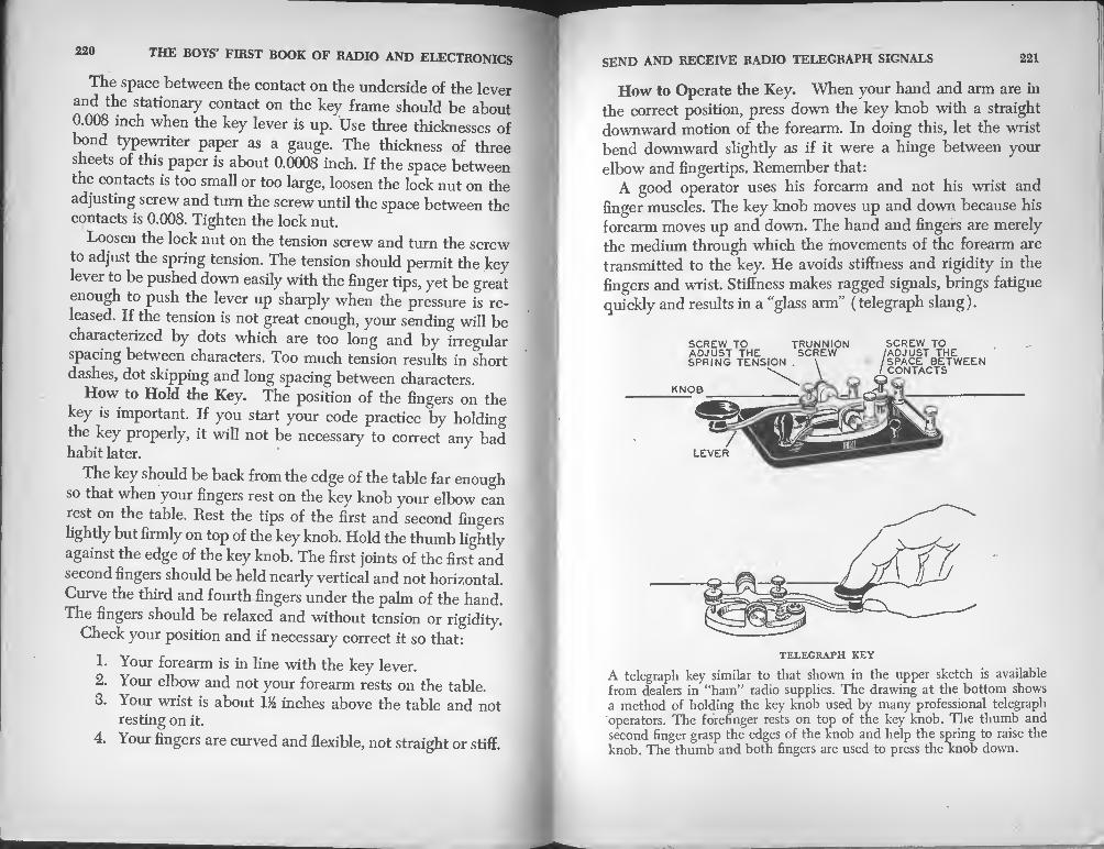
220 THE BOYS’ FIRST BOOK OF RADIO AND ELECTRONICS
The space between the contact on the underside of the lever
and the stationary contact on the key frame should be about
0.008 inch when the key lever is up. Use three thicknesses of
bond typewriter paper as a gauge. The thickness of three
sheets of this paper is about 0.0008 inch. If the space between
the contacts is too small or too large, loosen the lock nut on the
adjusting screw and turn the screw until the space between the contacts is 0.008. Tighten the lock nut.
Loosen the lock nut on the tension screw and turn the screw
to adjust the spring tension. The tension should permit the key
lever to be pushed down easily with the finger tips, yet be great
enough to push the lever up sharply when the pressure is re¬
leased. If the tension is not great enough, your sending will be
characterized by dots which are too long and by irregular
spacing between characters. Too much tension results in short
dashes, dot skipping and long spacing between characters.
How to Hold the Key. The position of the fingers on the
key is important. If you start your code practice by holding
the key properly, it will not be necessary to correct any bad habit later.
The key should be back from the edge of the table far enough
so that when your fingers rest on the key knob your elbow can
rest on the table. Rest the tips of the first and second fingers
lightly but firmly on top of the key knob. Hold the thumb lightly
against the edge of the key knob. The first joints of the first and
second fingers should be held nearly vertical and not horizontal.
Curve the third and fourth fingers under the palm of the hand.
The fingers should be relaxed and without tension or rigidity.
Check your position and if necessary correct it so that:
1. Your forearm is in line with the key lever.
2. Your elbow and not your forearm rests on the table.
3. Your wrist is about IJ2 inches above the table and not resting on it.
4. Your fingers are curved and flexible, not straight or stiff.
SEND AND RECEIVE RADIO TELEGRAPH SIGNALS 221
How to Operate the Key. When your hand and arm are in
the correct position, press down the key knob with a straight
downward motion of the forearm. In doing this, let the wrist
bend downward slightly as if it were a hinge between your
elbow and fingertips. Remember that:
A good operator uses his forearm and not his wrist and
finger muscles. The key knob moves up and down because his
forearm moves up and down. The hand and fingers are merely
the medium through which the movements of the forearm are
transmitted to the key. He avoids stiffness and rigidity in the
fingers and wrist. Stiffness makes ragged signals, brings fatigue
quickly and results in a “glass arm” (telegraph slang).
SCREW TO TRUNNION SCREW TO
A telegraph key similar to that shown in the upper sketch is available
from dealers in “ham” radio supplies. The drawing at the bottom shows
a method of holding the key knob used by many professional telegraph
operators. The forefinger rests on top of the key knob. The thumb and
second finger grasp the edges of the knob and help the spring to raise the
knob. The thumb and both fingers are used to press the knob down.

222 THE BOYS’ FIRST BOOK OF RADIO AND ELECTRONICS
When the key contacts have been closed by a downward
motion of the forearm, release the pressure on the knob and
allow the spring to return it to the “up” position. Keep the
thumb and fingers in light contact with the key knob. Do not
raise them off the knob to allow the spring to return the key
lever to the up’ position. Do not “tap” on the knob. A tele-
graph operator’s thumb and fingers never leave the key knob until he has finished sending his message.
Transmitting Exercises. Place your code practice set on a
able far enough back from the front edge so that you can take
the correct sending position. Grasp the key and start making
dots by pressing down the knob and releasing it immediately
so that the buzzer makes a “dit” sound each time the key is
pressed. Make dots at the rate of about 100 per minute. Do not
make anything but dots. Try constantly to make the dots equal.
If your arm and fingers become tired, rest for a short time, then
transmit again. When you can transmit 30 dots in one group
smoothly in about 10 seconds, you are ready to begin the next exercise.
Transmit the character V. It sounds like dit dit dit dah when
made correctly. Hold the key down for the dah 3 times as long
as you do to make a dit. Make the same time interval between
the dits and between the third dit and the dah. Send smoothly
It you are trying to transmit faster than you should your send¬
ing will be rough. Send the V’s at the rate of about 35 per min¬
ute. When you can send 20 consecutive V’s smoothly at the
rate of 35 per minute, you are ready to practice any letter in the code. J
Learning to telegraph is like learning to play a musical in¬
strument-practice helps more than anything else. Memorizing
the code and learning to make the sounds of the characters are
not the ultimate goal. Accuracy and speed are desirable. If you
can get the assistance of an experienced operator, perhaps
some one who already has an amateur radio operator’s license
and who will coach and criticize your sending, you will be in
SEND AND RECEIVE RADIO TELEGRAPH SIGNALS 223
luck and progress more rapidly. Don’t think that speed is im¬
portant at first. Accuracy is more important. Speed will come
with practice.
The best substitute for the assistance of an experienced oper¬
ator is for two beginners to practice together—to take turns
sending to each other with the code practice set.
Write down—“copy” it is called—the signals sent you, in the
form of letters, numerals, and punctuation marks. Do not copy
them as dots and dashes, for example, do not write a dot and
dash for the letter A, write the letter A. If you do not recognize
a character, leave a blank space. Do not think about an unrecog¬
nized character too long or you will miss the next signal. When
you can send and receive 65 letters, numerals and punctuation
marks per minute and copy them accurately, whether they
make sense or not, you can pass a government code test. If you
can pass the test and answer a few questions, you can obtain a
“ham” operator’s license.


INDEX
A Battery, 180 Alternating Current, 21
high frequency, 22 AM (amplitude modulation), 4
Amateur, early receiver, 18 transmitter 75 years ago, 14
Ampere, 24 Amplifiers, 43, 186-205
experiments with, 201
how to build, 186-205 one-stage audio, 189 resistance coupled, 196 transformer coupled, 186-19 two-stage, 194-200
Amplitude Modulation, 47
Anode, 90 Antenna, 44, 206-210
apartment house, 208 indoor, 210
Antenna Insulators, 205 Antenna Tower, 30 Armstrong, Edwin H., 43, 48 Arnold, H. D„ 42 Attraction, electrical, 38 Audio Amplifiers, 186-203 Audio Transformer, 190 Audion, 42, 91
Bardeen, John, 124 Battery, A, 180
B, 180 Battery Power, 180 Beacons, radio, 57 Beat Frequency, 105 Bimorph Crystals, 74
Block Diagrams, 45 Body Effect, 113 Branly, Eduard, 8
coherer, 8, 9 Brattain, W. H., 124 Buzzer, test, 156
Cables, coaxial, 47 Capacitors, fixed, 109
trimmer, 168 variable, 111
Capacity, 110 Carborundum, 118 Cathode, 90, 92 Cathode-ray tube, 33 Cavity Magnetron, 97, 105 Charge, electrical, 38 Coaxial Cables, 47 Code, color, 108
Continental, 217
practice set, 218 Coherer, 8-10, 18
amateur, 18 Coils, broadcast band, 184
loading, 151 plug-in, 168 winding, 184
Color Code, resistor, 108 Condensers, fixed, 109
trimmer, 168 variable, 111
Conductors, 22 Continental Code, 217 Controls, volume, 109 Crookes, William, 84

228 229 THE BOYS’ FIRST BOOK OF RADIO AND ELECTRONICS INDEX
Crystals, 118
Crystal Detectors, 118-125
Curie, Pierre and Jacques, 73 Current, alternating, 21
direct, 21
electric, 21, 22
high-frequency, 22 Cycle, 22
Cyclotron, 105
De Forest, Dr. Lee, 41
Depth Finder, 83
Detectors, adjustment of, 156 audion, 42, 91
crystal, 118-125 feedback, 102
first amateur, 15
microphonic, 15 Solari, 12
triode, 99
Diagrams, block, 45 pictorial, 26
schematic, 26 symbols for, 25
Dials, tuning, 167
Dielectric, 110 Diodes, 90,124
Germanium, 124 Direct Current, 21
Direction Finder, 58
Dunwoody, H. H., 118
East Goodwin, 1
Edison Effect, 39, 41 Edison, Thomas A., 39
Electrical Attraction, 38 Electrical Charge, 38
Electrical Measurements, 23 Electric Current, 21, 22 Electric Waves, 32-36
discovery of, 3 speed of, 4
Electricity, facts about, 20 Electrode, 39
Electromagnetic Induction, 101 Electron Gun, 48, 64
Electron Tube Oscillators, 103 Electronic Night Sight, 33 Electronics, 37-88
applications of, 86-88 Electrons, 21, 37-88
Energy, electrical, 20 Entwhistle, 12
Experiment, with amplifier, 200 with electrical charge, 38
Farad, 110
Faraday, Michael, 110
Feedback, 100-103
Fessenden, Reginald A., 16-17
First Radio Broadcast, 16
First Transatlantic Receiving Station, 13
First Wireless Telegraph, 1 aboard Atlantic liner, 2
First Wireless Telephone, 1 Fleming, Sir John A., 11, 39 Flying Huntress, 11
FM (frequency modulation), 47 Frequencies, tubes for high-, 95 Frequency, 22, 31,105
beat, 105
Fuse, proximity, 56
Galena, 120
Germanium Diodes, 124 Grid, 90 Ground, 211
Ground Waves, 35
Headset, 114
Hertz Apparatus, 4, 5
Hertz, Heinrich Rudolph, 3, 69
Hertzian Waves, 27-36 High-frequency Alternating Cur¬
rents, 22 Hook-up Wire, 117
Iconoscope, 62 Image Orthicon, 62 Induction, Electromagnetic, 101
Insulators, 22 antenna, 207
Ionosphere, 35 ( Iron Pyrites, 123
Kaiser Wilhelm der Grosse, 2 Key, telegraph, 221
Keyer, 46 Kinescope, 66
Langmuir, Irving, 42
Lead-in, 209 Lighthouse Tubes, 96 Lightning, 209, 210
arrestor, 210 Loading Coil, 151 Loran, 60-61 Loudspeakers, 115
Magnetron, 97, 105 Marconi, Guglielmo, 6-16 Marine Radio Beacons, 57 Maxwell, James Clerk, 3 Measurements, electrical, 23 Microfarad, 110 Micromicrofarad, 110 Microphone, how to make, 202
experiments with, 201-203 Minerals, 118 Miniature Tubes, 96 Modulation, 46 Modulator, 46 Motion Pictures, 71
National Electric Signalling Co.,
18
Oscillation Valve, 41 Oscillator, 44, 89, 103
Hertz, 4
Oscilloscope Tube, 48, 53
Pentode, 92 Phonograph, pickups, 74, 76
records, 75 reproducer, 75
Photocell, 69 Phototubes, 68-72 Pickard, Greenleaf W., 118 Pickup, phonograph, 74, 76 Piezo-electric Effect, 72 Piezo-electric Transducer, 77 Piezotronics, 72 Pip, 53 Plug-in Coils, 168
how to wind, 184 Preece, Sir William, 11 Pulses, radar, 54
Quartz Crystals, 73
Radar, 50-56 Radar Proximity Fuse, 56 Radio, meaning of word, 29 Radiobeacons, 57 Radio Receivers
how to build, 126-183 how to operate, 144, 179 regenerative, 160 with crystal detector and
single-slider tuner, 129 with crystal detector and
double-slider tuner, 140 with crystal detector and
coupler, 144 with vacuum tube detector
and capacitor tuning, 160

THE BOYS FIRST BOOK OF RADIO AND ELECTRONICS
Radio Receivers, continued tuned, 127 untuned, 127 wiring, 178
Radiotelegraph Signals, learning to receive, 216
Radiotelegraphy, 44
principle of, 45 Radiotelephony, 44
Radio Tubes, development of, 40 Radio Waves, 27-36
Receivers, telephone, 113 television, 67
Reflection of Waves, 33 Refraction of Waves, 32 Regeneration, 100-103
Regenerative Receiver, how to build, 160.
Repeater, telephone, 186
Reproducer, motion picture, 71 phonograph, 75
Resistance-coupled Amplifier, * 196
Resistor Color Code, 108 Resistors, 107
Rochelle Salt, 74
Scanning, 65 Silicon, 122
Skip Distance, 36 Sky-waves, 35
Solder, how to , 211
Soldering Iron Rest, 214 Soldering Irons, 212 Sonar, 82
Sound Head, 71 Sound Track, 70 Sounds, 78-82 Speakers, 115
Stoney, G. Johnstone, 38
Superheterodyne Receiver, 105
Supersonics, 78-83 Symbols, radio, 25
Tapper, 9
Telegraph Code, 217 Telegraph Key, 221
Telephone Receivers, 113 Telephone Repeater, 186
Telephone Transmitter, 200 Television, 62-68 Test Buzzer, 156 Tetrode, 92 Tickler Coil, 101
Transducer, 77, 80
•Transformer, audio, 190 Transistor, 124
Transmitter, Hertzian, 5 radiotelegraph, 45
radiotelephone, 46 television, 67
Transmitting Tubes, 104 Trap, Wave, 151
Trimmer Capacitors, 168 Triode, 90
detector, 100
Trouble Shooting, 182
Tubes, high-frequency, 95 lighthouse, 96 miniature, 96 oscilloscope, 48
‘radio, 89-105
transmitting, 104 Tuner, single-slider, 129
capacitor, 160
double-slider, 140 Tuning, 126
dials and knobs, 167
Ultrasonics, 78-83
Valve, oscillation, 41
Variable Reluctance Pickup, 76 Volume Controls, 109, 176
Walkie Talkie, 34