first beam of spes source at lnl -...
TRANSCRIPT

First Beam of SPES Source at LNL
E. Fagotti1, A. Palmieri1, L. Boscagli1, M. Lollo1, S. Marigo1, M. Poggi1, C. Roncolato1, M. Sattin1, S. Vitulli2
1 INFN Laboratori Nazionali di Legnaro, 2 Fondazione CNAO, Pavia
INTRODUCTION
In November 2005, SPES source was transferred from LNS to LNL [1]. Owing to incomplete site preparation, the installation was finished only in late July 2006. First beam was extracted at the end of September 2006. The main issues encountered during installation and related solutions that allowed first beam extraction are here reported.
SPES SOURCE INSTALLATION
Five main problems caused a six months schedule shifting in the installation plan:
• floating floor installation • extraction column support machining • high voltage shielding • high voltage cage installation • cooling system installation.
Due to a delay in the floating floor installation, we could not set up the ground components (90 kV power supply, insulator transformer and control rack) but in the middle of January. Another month passed to install the column support and the extraction column itself. We had to wait the end of March in order to have the x-ray concrete shielding and the end of May for high voltage cage. After completing high voltage protection, four days have been necessary to carry out the installation with the provisional LEBT.
FIG.1: SPES source installation before summer.
The system was tested at full power at the end of July after cooling system installation. Up to this moment we were not able to test the complete control system, because of some interlocks on water cooling. During control system tests a problem in SAIREM magnetron remote reset
occurred, which prevented the remote start of the microwave generator after each spark. The problem was solved after the installation of a magnetron software update, provided by the company. Vacuum system was successfully tested before summer stop and therefore the installation was completed and tested before summer (see figure 1).
TAB.1: Cooling system specification
Required LNL system New system Pin,Lab (bar) 5 5 5 Pout,Lab (bar) - 2.5-3.0 2.5-3.0 Pout,HV (bar) 1 2.5-3.0 1 ΔPHV (bar) 4 2.5-2.0 4 m (l/min) 35 22-12 45
Cooling system tests revealed that water flux in high
voltage platform circuit was below the specification, because of an insufficient pressure gradient due to a high pressure in the outlet circuit. In order to increase the water mass flow rate inside platform, we modified the cooling system adding an open tank and a pumping station between the platform outlet and the general outlet circuit. In other words, water going out from platform is poured in the tank, which is at atmospheric pressure. Here it is pumped to the general outlet circuit through a frequency variable pumping system maintaining a constant water level in the tank. With this system it is possible to keep a constant mass flow rate in the platform, independently from the pressure in the general outlet circuit (see table 1).
SPES SOURCE COMMISSIONING
After summer stop, all sub-systems were tested again and the high voltage conditioning was started. In a few days it was possible to get an extraction voltage of 85 kV. During conditioning some problem concerning the electromagnetic noise generated by external discharges was discovered. We fixed the problem by setting up electromagnetic filters and by optimizing cables distribution. In addition, the power supplies of intermediate and repeller electrodes in the high voltage cage were moved, filtering their main connections with an insulation transformer. During voltage conditioning, the maximum equivalent dose rate measured has been 0.2 μSv/h. Plasma chamber conditioning with RF power encountered some problems of discharge that forced us to open the extraction column for the first time. All the electrodes and the plasma
·
chamber passed mechanical and chemical cleaning. The cleaning allowed shortening the time of the new high voltage conditioning up to 3 hours. Extraction efficiency increased with conditioning time (see table 2).
TAB.2: Source performances during commisioning.
Power (W) Pline (mbar) IPS (mA) 1st day 430 9.5*10-6 27 4th day 450 1.6*10-5 48
The extraction current was measured as the absorbed
current of the 90 kV power supply. It is very close to the beam current, considering that the absorbed current without beam load is only 0.72 mA and the absorbed current of puller and repeller electrodes is independent on the load. We measured a 70 % of the extracted current at the end cup location. This current reduction was due to a significant fraction of the beam that got lost on the water cooled collimator installed in front of the end cup. This loss is caused by a strong beam misalignment generated by poor electrodes assembly (see figure 2). We will be able to measure the real current after extraction column realignment.
FIG.2: Beam seen from the viewport. Misalignment can be evaluated respect to the circular flange behind the beam (flange center is on the ideal beam axis).
The equivalent dose rate prompt radiation was measured even during plasma chamber conditioning and during beam extraction. Results were in perfect agreement with LNS radioprotection measurements. The maximum average dose rate measured out of the cage was 0.1μSv/h, while the maximum measured in the platform, near the impact point of backscattering electrons, was 1.4 μSv/h.
BEAM PROFILE MEASUREMENT
In order to make a destructive "high" power test on the new grid profilers for the ALPI accelerator [2], the provisional LEBT was modified by inserting a new diagnostic box (see figure 3). Grids were constituted by tungsten wires alternated with carbon wires to test their behavior with a high power beam. Obviously, power
generated by ALPI accelerator is much lower than power generated by SPES source. Therefore we tested grids with 4 mA beam at maximum (corresponding to 320 W beam power at 80 kV).
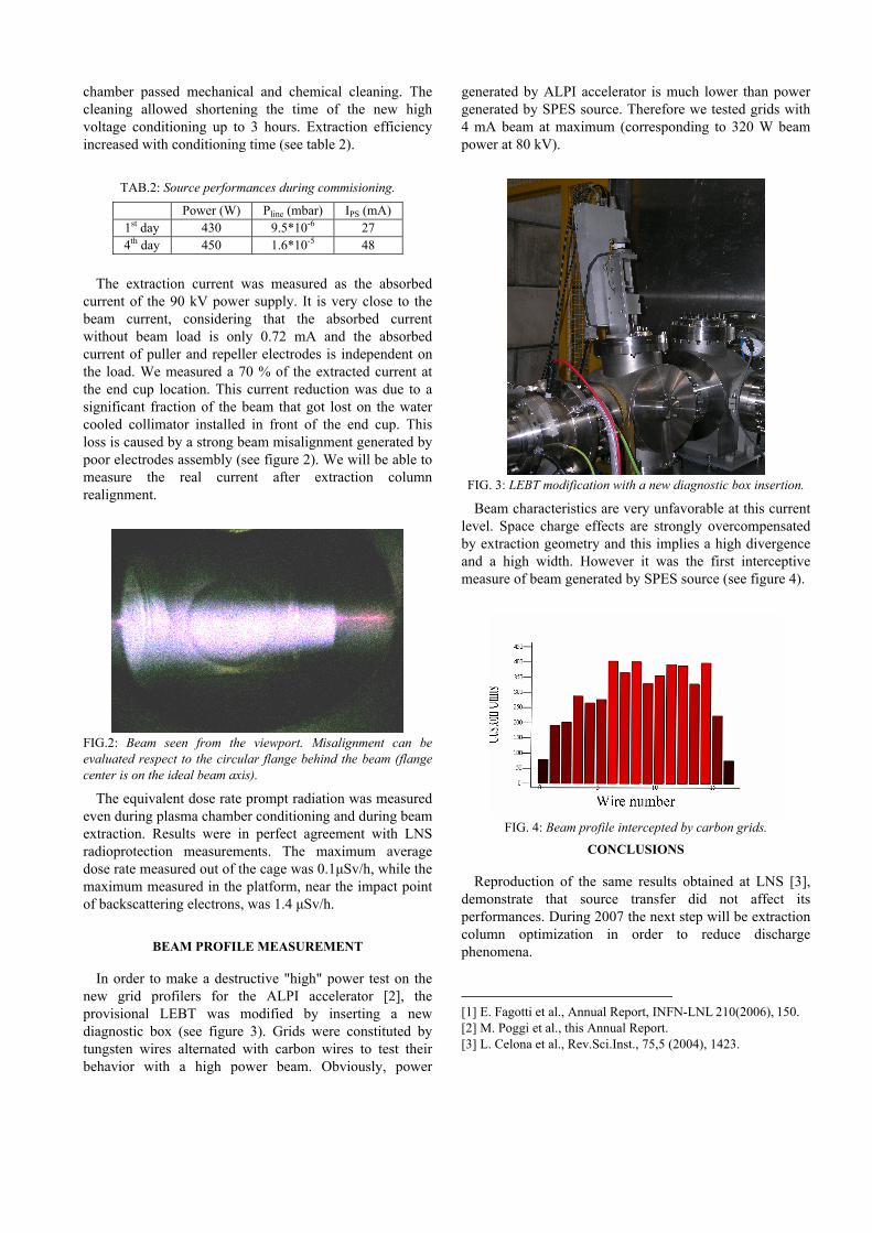
FIG. 3: LEBT modification with a new diagnostic box insertion.
Beam characteristics are very unfavorable at this current level. Space charge effects are strongly overcompensated by extraction geometry and this implies a high divergence and a high width. However it was the first interceptive measure of beam generated by SPES source (see figure 4).
FIG. 4: Beam profile intercepted by carbon grids.
CONCLUSIONS
Reproduction of the same results obtained at LNS [3], demonstrate that source transfer did not affect its performances. During 2007 the next step will be extraction column optimization in order to reduce discharge phenomena.
[1] E. Fagotti et al., Annual Report, INFN-LNL 210(2006), 150. [2] M. Poggi et al., this Annual Report. [3] L. Celona et al., Rev.Sci.Inst., 75,5 (2004), 1423.