firewall architecturesd2zmdbbm9feqrf.cloudfront.net/2013/usa/pdf/brksec-2021.pdf · firewall...
TRANSCRIPT

Firewall Architectures
BRKSEC-2021
Mason Harris CCIE#5916
Solutions Architect
Global Enterprise

© 2013 Cisco and/or its affiliates. All rights reserved. BRKSEC-2021 Cisco Public
Guide to Icons
3
ASA Firewall L3 Switch (Nexus 7K/Cat 6500)
ASA1000V Virtual Firewall
Virtual Security Gateway
Virtual Firewall

© 2013 Cisco and/or its affiliates. All rights reserved. BRKSEC-2021 Cisco Public
Related Sessions
BRKSEC - 2003 – IPv6 Security Threats and Mitigation
BRKSEC – 2020 – Firewall Deployment
BRKSEC – 2205 – Security and Virtualization in the Data Center
BRKSEC – 3020 – Troubleshooting Firewalls
BRKSEC – 3021 – Maximizing Firewall Performance
BRKVIR – 2011 – Deploying Services in a Virtualized Environment
4

© 2013 Cisco and/or its affiliates. All rights reserved. BRKSEC-2021 Cisco Public
Agenda
Introduction
Physical vs. Virtual Firewalls
Firewall High Availability
Visibility
IPv6 Access Control
Putting It All Together
Summary and Conclusions
5
INTRODUCTION

© 2013 Cisco and/or its affiliates. All rights reserved. BRKSEC-2021 Cisco Public
Introduction
This session was created new last year in response to feedback over the years from my previous session BRKSEC-2020 (Firewall Design and Deployment)
Cisco has many different types of firewalls, this session will share good deployment options and things to avoid
The intent of this session is to take a macro approach to the firewall
Best practices and gotchas/caveats will be shared and discussed
This session does not cover IOS firewall, Firewall Services Module (FWSM) or ASA Next Generation Firewall
Please ask questions, we’ll be moving fast
7

PHYSICAL FIREWALLS AND VIRTUAL FIREWALLS

© 2013 Cisco and/or its affiliates. All rights reserved. BRKSEC-2021 Cisco Public
Physical Firewalls: Service Modules and Appliances
Cisco currently only has one service module firewall, the ASA SM for the Catalyst 6500-E
SM firewalls have no physical interfaces and rely entirely on the existing switching infrastructure for packet flow
It uses VLANs to redirect which packets are inspected or bypassed
Appliance firewalls can be deployed in more places in the network but require physical cabling
Additional services are available (e.g. remote access VPN) on physical firewalls that don’t exist on blade firewalls (yet)
Both types support multi-context mode
Both types support routed mode and transparent mode firewalling
9

© 2013 Cisco and/or its affiliates. All rights reserved. BRKSEC-2021 Cisco Public
Physical Firewalls: Service Modules
10
ASA SM supported only in Cat 6500-E chassis today
Critical design around SVI placement for L3
Up to 4 ASA SMs in one 6K chassis
~16gbs multiprotocol throughput per blade
Runs ASA code
No VPN support today except for management (future release)
No clustering support today (future release)

© 2013 Cisco and/or its affiliates. All rights reserved. BRKSEC-2021 Cisco Public
Physical Firewalls: ASA 5585 Appliances
11
2 slots (2 RU): FW+FW, FW+IPS or FW+NGFW
Top end 5585s provide 4 10GE ports (SFP)
I/O card or additional IPS module will add 4 more 10GE ports
20 GBps multiprotocol per appliance (5585-60)
10M connections per appliance (5585-60)
BreakingPoint Test Results: http://blogs.ixiacom.com/ixia-blog/cisco-asa-live-validation-with-breakingpoint-firestorm-ctm/
Miercom report here: http://www.miercom.com/2011/06/cisco-asa-5585-x-vs-juniper-srx3600/

© 2013 Cisco and/or its affiliates. All rights reserved. BRKSEC-2021 Cisco Public
Virtualized Firewalls and Virtual Firewalls
Two types: multi-context mode and virtual firewalls
Multi-context mode was originally designed for SMT (Secure Multi Tenant) deployments and is a licensed feature
Virtual firewalls are software-only firewalls running in a hypervisor
Cisco has two virtual firewalls: the Virtual Security Gateway (VSG) and the ASA1000V
Both require the Nexus 1000V distributed virtual switch and an “Advanced” license
Virtual firewalls can be deployed rapidly with typical orchestration tools, etc. but there is an added layer of operational complexity
Virtual firewalls are heavily dependent on available RAM and CPU on the host server
We’ll cover virtual firewalls in the next section
12

© 2013 Cisco and/or its affiliates. All rights reserved. BRKSEC-2021 Cisco Public
Virtualized Firewalls
13
VFW
1
VFW
2
VFW
3
VFW
4
Multiple virtual firewalls in one physical chassis
Each virtual firewall is considered a “context”
Maximum number of virtual firewalls in one physical appliance is 250
Physical interfaces are mapped to contexts and each context maps to a configuration
Commonly deployed in VRF environments at intersection points

© 2013 Cisco and/or its affiliates. All rights reserved. BRKSEC-2021 Cisco Public
System Context:
Physical ports assigned
How the Virtualized Firewall is Configured
Context = a virtual firewall
All virtualized firewalls must define a System context and an Admin context
Admin Context:
Remote root access and
access to all contexts
Virtual Firewall
contexts
VFW
1
VFW
2
VFW
3
Admin
System
There is no policy inheritance between contexts
The system space uses the admin context for network connectivity; system space creates other contexts
14
© 2013 Cisco and/or its affiliates. All rights reserved. BRKSEC-2021 Cisco Public
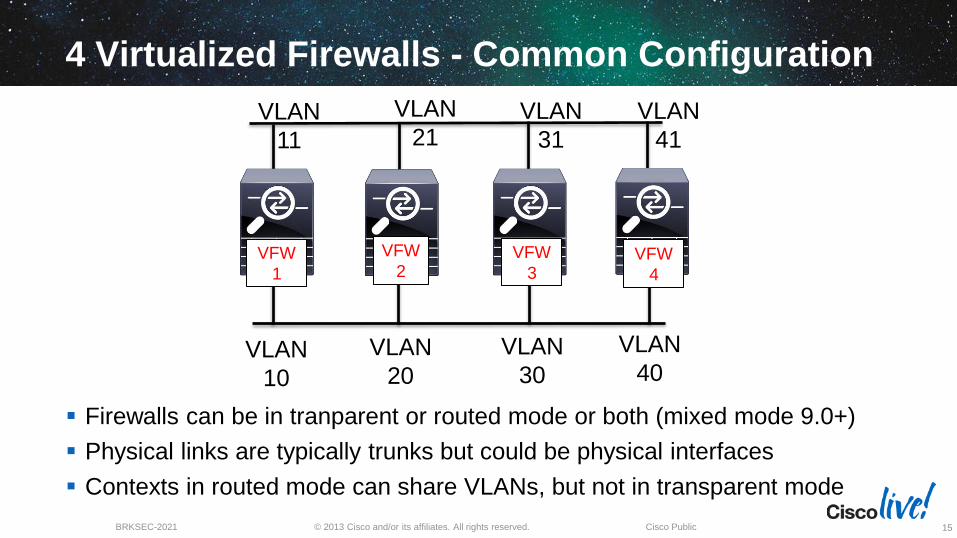
4 Virtualized Firewalls - Common Configuration
15
Firewalls can be in tranparent or routed mode or both (mixed mode 9.0+)
Physical links are typically trunks but could be physical interfaces
Contexts in routed mode can share VLANs, but not in transparent mode
VLAN
10
VLAN
20
VLAN
30
VLAN
40
VLAN
11
VLAN
21 VLAN
31
VLAN
41
VFW
1
VFW
2 VFW
3 VFW
4

© 2013 Cisco and/or its affiliates. All rights reserved. BRKSEC-2021 Cisco Public
Multi Context Mode Configuration System Context Configuration
16
interface Ethernet0/0
!
interface Ethernet0/0.1
vlan 10
!
interface Ethernet0/0.2
vlan 20
!
interface Ethernet0/1
!
interface Ethernet0/1.1
vlan 11
!
interface Ethernet0/1.2
vlan 21
!
interface Ethernet0/2
!
interface Ethernet0/3
!
class default
limit-resource All 0
limit-resource ASDM 5
limit-resource SSH 5
limit-resource Telnet 5
!
admin-context admin
context admin
allocate-interface Ethernet0/2 outside
allocate-interface Ethernet0/3 inside
config-url disk0:/admin.cfg
!
context vfw1
allocate-interface Ethernet0/0.1 outside-vfw1
allocate-interface Ethernet0/1.1 inside-vfw1
config-url disk0:/context1.cfg
!
context vfw2
allocate-interface Ethernet0/0.2 outside-vfw2
allocate-interface Ethernet0/1.2 inside-vfw2
config-url disk0:/context2.cfg

© 2013 Cisco and/or its affiliates. All rights reserved. BRKSEC-2021 Cisco Public
Multi Context Mode Configuration
VFW1 Context Configuration
17
ciscoasa/vfw1 (config)# show run
ASA Version 9.0
!
hostname vfw1
enable password 8Ry2YjIyt7RRXU24 encrypted
!
interface inside-vfw1
nameif inside
security-level 100
ip address 172.17.1.1 255.255.255.0
!
interface outside-vfw1
nameif outside
security-level 0
ip address 10.2.2.1 255.255.255.0

© 2013 Cisco and/or its affiliates. All rights reserved. BRKSEC-2021 Cisco Public
To Virtualize the ASA or Not?
Good fit for SPs who want to deploy a single appliance for multiple customers
Good fit for VRF segmentation where VLANs map to VRFs
Can’t virtualize CPU or memory, careful for network surges
Can’t easily share interfaces in transparent (L2) mode
Operationally more complex, management tools treat each context like a separate firewall
Licensed feature $$$
Some features aren’t compatible with virtualization
Can’t easily “reboot” a context
18

DEPLOYMENT MODES

© 2013 Cisco and/or its affiliates. All rights reserved. BRKSEC-2021 Cisco Public
Firewall Design: Modes of Operation
Routed Mode is the traditional mode of the firewall. Two or more interfaces that separate L3 domains
Transparent Mode is where the firewall acts as a bridge functioning mostly at L2
Multi-context mode involves the use of virtual firewalls, which can be either routed or transparent mode
Mixed mode is the concept of using virtualization to combine routed and transparent mode virtual firewalls
ASA 9.0 release brings mixed mode support
20

© 2013 Cisco and/or its affiliates. All rights reserved. BRKSEC-2021 Cisco Public
Firewall - Routed Mode
10.1.1.1 - inside
10.99.1.1 - outside
10.99.1.0 /24
10.1.1.0 /24
hostname ciscoasa
!
interface GigabitEthernet0/0
nameif outside
security-level 0
ip address 10.99.1.1 /24
!
interface GigabitEthernet0/1
nameif inside
security-level 100
ip address 10.1.1.1 /24
!
21

© 2013 Cisco and/or its affiliates. All rights reserved. BRKSEC-2021 Cisco Public
What is a Transparent mode Firewall?
22
Transparent Firewall (L2) mode provides an option in traditional L3 environments where existing services can’t be sent through the firewall
Very popular architecture in data center environments
In L2 mode:
– Routing protocols can establish adjacencies through the firewall
– Protocols such as HSRP, VRRP, GLBP can pass
– Multicast streams can traverse the firewall
– Non-IP traffic can be allowed (IPX, MPLS, BPDUs)
– Allows for three forwarding interfaces, inside and outside and DMZ
– NO dynamic routing protocol support or VPN support
– Specific design requirements, reference Configuration Guide for details

© 2013 Cisco and/or its affiliates. All rights reserved. BRKSEC-2021 Cisco Public
How Does Transparent Mode Work?
Firewall functions like a bridge (“bump in the wire”) at L2, only ARP packets pass without an explicit ACL
Still can use traditional ACLs on the firewall
Does not forward Cisco Discovery Protocol (CDP)
Same subnet exists on all interfaces in the bridge-group
Different VLANs on inside and outside interfaces
In addition to Extended ACLs, use an EtherType ACL to restrict or allow L2 protocols
23

© 2013 Cisco and/or its affiliates. All rights reserved. BRKSEC-2021 Cisco Public
Transparent Mode Requirements
A BVI address is required for both management and for traffic to pass through the transparent firewall
Set default gateways of hosts to L3 on far side of firewall, NOT the management IP of firewall
Up to 4 interfaces are permitted per bridge-group
In multi-context mode an interface can not be shared among contexts (virtual firewalls)
24

© 2013 Cisco and/or its affiliates. All rights reserved. BRKSEC-2021 Cisco Public
10.1.1.0 /24 – vlan 10
10.1.1.0 /24 – vlan 20
BVI 1: 10.1.1.100 /24
(Bridge Virtual Interface)
firewall transparent
hostname ciscoasa
!
interface GigabitEthernet0/0
vlan 20
nameif outside
security-level 0
bridge-group 1
!
interface GigabitEthernet0/1
vlan 10
nameif inside
security-level 100
bridge-group 1
!
interface BVI1
ip address 10.1.1.100 255.255.255.0
Transparent Mode Configuration (2 interfaces)
Brid
ge
-gro
up
1
25

TRANSPARENT MODE FW ARCHITECTURE

© 2013 Cisco and/or its affiliates. All rights reserved. BRKSEC-2021 Cisco Public
L2 FW Between Two L3 Devices
ISP-A
ISP-B
L3 Routed
Core Fully
Meshed BGP
27
© 2013 Cisco and/or its affiliates. All rights reserved. BRKSEC-2021 Cisco Public
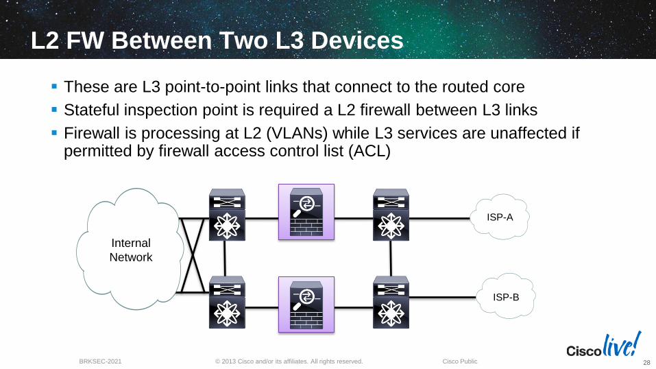
L2 FW Between Two L3 Devices
These are L3 point-to-point links that connect to the routed core
Stateful inspection point is required a L2 firewall between L3 links
Firewall is processing at L2 (VLANs) while L3 services are unaffected if permitted by firewall access control list (ACL)
ISP-A
ISP-B
Internal
Network
28

© 2013 Cisco and/or its affiliates. All rights reserved. BRKSEC-2021 Cisco Public
L2 FW Logical View
ISP-A
ISP-B
Internal
Network
Active
Firewall
Standby
Firewall
HA
Interconnects Trunks
29
© 2013 Cisco and/or its affiliates. All rights reserved. BRKSEC-2021 Cisco Public
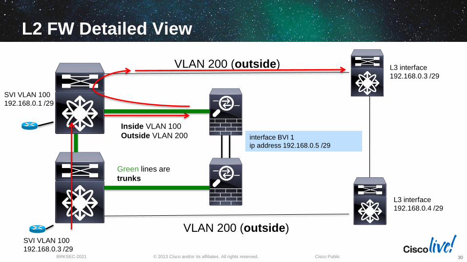
L2 FW Detailed View
Inside VLAN 100
Outside VLAN 200
SVI VLAN 100
192.168.0.3 /29
VLAN 200 (outside)
interface BVI 1
ip address 192.168.0.5 /29
L3 interface
192.168.0.4 /29
VLAN 200 (outside)
Green lines are
trunks
L3 interface
192.168.0.3 /29
SVI VLAN 100
192.168.0.1 /29
30
© 2013 Cisco and/or its affiliates. All rights reserved. BRKSEC-2021 Cisco Public
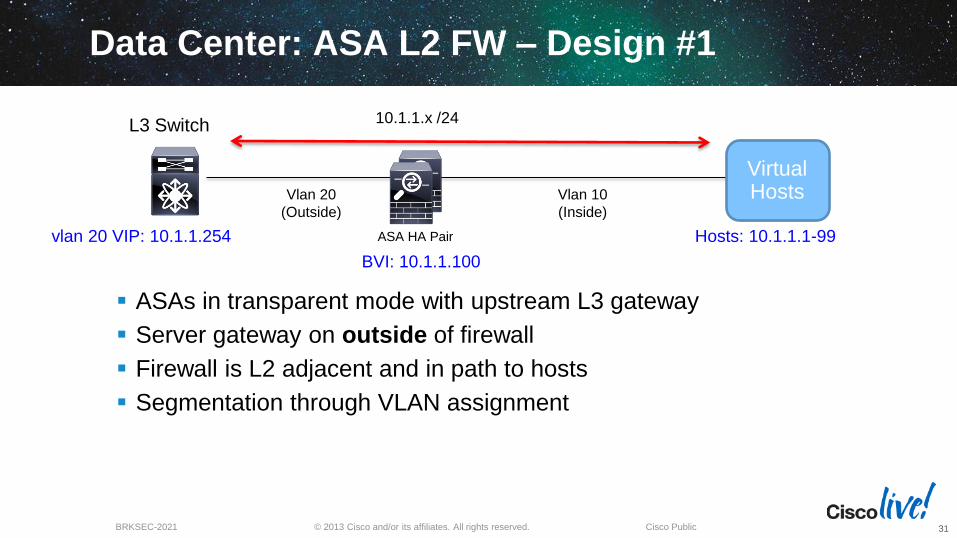
Data Center: ASA L2 FW – Design #1
ASAs in transparent mode with upstream L3 gateway
Server gateway on outside of firewall
Firewall is L2 adjacent and in path to hosts
Segmentation through VLAN assignment
Vlan 10
(Inside)
vlan 20 VIP: 10.1.1.254
L3 Switch
Hosts: 10.1.1.1-99
10.1.1.x /24
Vlan 20
(Outside)
ASA HA Pair
BVI: 10.1.1.100
Virtual Hosts
31

© 2013 Cisco and/or its affiliates. All rights reserved. BRKSEC-2021 Cisco Public
Data Center: ASA L2 FW – Design #2
Agg-VDC-Out
Outside Inside
Agg-VDC-In
HSRP VIP: 10.1.1.254
Single L2 Domain
Firewalls for Intra-VDC Traffic
ASA in either L2 or L3 mode, L2 is optimal in most cases
Add VRFs on Cat 6500 or Nexus 7K for segmentation
Server gateway inside of firewall
Minimizes firewall failures, route around failures if needed
Virtual Hosts vlan 20 vlan x vlan y
10.199.199.2 10.199.199.1
32

© 2013 Cisco and/or its affiliates. All rights reserved. BRKSEC-2021 Cisco Public
N7k1-VDC-2 Aggregation
vrf1 vrf2
ASA L2 FW – Design #3
Transparent (L2) firewall services are “sandwiched” between Nexus VDCs
Allows for other services (IPS, LB, etc) to be layered in as needed
ASAs can be virtualized to for 1x1 mapping to VRFs
Useful for topologies that require a FW between aggregation and core
Downside is that most/all traffic destined for Core traverses FW; possible bottleneck, etc.
Firewalls could be L2 or L3
N7k1-VDC-1 Core
vrf1 vrf2
Firewalls for Inter-VDC Traffic
33

VIRTUAL FIREWALLS

© 2013 Cisco and/or its affiliates. All rights reserved. BRKSEC-2021 Cisco Public
Centralized or Decentralized Firewalls or Both?
Centralized firewalls are the traditional approach to virtualized host security
Often a transitional architecture
Firewalls in the core, aggregation or edge?
Big challenge is scalability
Usually the limiting factor is connections not bandwidth
How to handle a requirement for L2 separation of hosts?
How to address virtual host mobility?
35
Virtual Hosts
Virtual Hosts
Physical
Hosts

© 2013 Cisco and/or its affiliates. All rights reserved. BRKSEC-2021 Cisco Public
Cisco’s Virtual Firewalls: VSG and ASA1000V
Cisco has two virtual firewalls: the ASA 1000V and the Virtual Security Gateway (VSG)
Each runs as a virtual machine in VMWare (future HyperV support)
Both are managed via Virtual Network Management Center (VNMC)
Both are licensed per CPU socket
They are complementary to each other and require the Nexus 1000V Distributed Virtual Switch and utilize a new forwarding plane, vPath
36
Virtual Security Gateway ASA 1000V

© 2013 Cisco and/or its affiliates. All rights reserved. BRKSEC-2021 Cisco Public
What are North-South and East-West Flows?
North-South (N-S) flows are typically flows to and from Access layer to Aggregation Layer and Core
East-West (E-W) flows typically stay either within a zone or between zones and often server to server traffic
37
Web App
Access
Aggregation
Core
Database
East - West
No
rth
- S
ou
th
Virtual Hosts
Virtual Hosts
Virtual Hosts

© 2013 Cisco and/or its affiliates. All rights reserved. BRKSEC-2021 Cisco Public
What is the ASA1000V Cloud Firewall?
ASA1000V is a software-only version of an ASA appliance—an edge firewall
Runs ASA codebase in a virtual machine in L3 mode only
Supports S2S IPSEC VPN (not RA VPN)
Can be deployed in active/standby HA
Subset of physical ASA features are supported, check docs for specifics (no multimode, no L2FW, etc)
Management via ASDM or VNMC but not both
Not a replacement for physical appliance!
38
Virtual Hosts
Virtual Hosts
Virtual Hosts
4 interfaces: inside, outside, failover and management

© 2013 Cisco and/or its affiliates. All rights reserved. BRKSEC-2021 Cisco Public
ASA 1000V Deployment: Public Cloud
39
Hosts Hosts Hosts
Cloud Service Provider
Company A
VM 1
VM 2
VM 3
VM 4
ASA 1000V
Physical ASA on Premise
Site-to-Site IPSEC VPN
VM 5
VM 6
VM 7
VM 8
Company A has moved to virtualized cloud based servers
Requires connectivity between existing hosts (physical or virtual)
ASA 1000V acts as default gateway to cloud servers, DHCP services etc
S2S IPSEC VPN tunnel connects existing infrastructure to cloud
Other VPN devices can establish S2S tunnels with ASA1000V
No RA VPN support (AnyConnect)

© 2013 Cisco and/or its affiliates. All rights reserved. BRKSEC-2021 Cisco Public
ASA 1000V Deployment with NAT
40
Hosts Hosts Hosts
Cloud Service Provider
Company A - PROD
VM 1
VM 2
VM 3
VM 4
ASA 1000V
Physical ASA on Premise
Site-to-Site IPSEC VPN
VM 5
VM 6
VM 7
VM 8
Company A - DEV
VM 1
VM 2
VM 3
VM 4
VM 5
VM 6
VM 7
VM 8
Company A clones cloud servers for Production and Development services
ASA 1000V can provide dynamic and static NAT as needed
NAT x-y

© 2013 Cisco and/or its affiliates. All rights reserved. BRKSEC-2021 Cisco Public
ASA 1000V Deployment: Internal Private Cloud
41
Zone 1 Zone 2 Zone 3
VM 1
VM 2
VM 3
VM 4
VFW 1
VM 5
VM 6
VM 7
VM 8
VFW 2 VFW 3
Today multi context mode on ASA is used to provide firewall inspection for multi tenant and multi zone environments
Trunks are typically used to transport zone and tenant traffic
Challenge of E-W scale requires more firewall resources
ASA 1000V provides edge firewall and can scale alongside E-W buildout
Each tenant or zone gets one or more ASA 1000V
Provides NAT and DHCP services for scale
Vzone 1 Vzone 2
Multi Context Mode ASA

© 2013 Cisco and/or its affiliates. All rights reserved. BRKSEC-2021 Cisco Public
What is the Virtual Security Gateway?
VSG is a L2 firewall that runs as a virtual machine “bump in the wire”
Similar to L2 transparent FW mode of ASA
It provides stateful inspection between L2 adjacent hosts (same subnet or VLAN)
It can use VMware attributes for policy
Provides benefits of L2 separation for East-West traffic flows
One or more VSGs are deployed per tenant
42
Virtual Hosts
Virtual Hosts
Virtual Hosts

© 2013 Cisco and/or its affiliates. All rights reserved. BRKSEC-2021 Cisco Public
VM Attributes Used by VSG (Partial List)
Name Meaning Source
vm.name Name of this VM vCenter
vm.host-name Name of this ESX-host vCenter
vm.os-fullname Name of guest OS vCenter
vm.vapp-name Name of the associated
vApp
vCenter
vm.cluster-name Name of the cluster vCenter
vm.portprofile-name Name of the port-profile Port-profile
43

© 2013 Cisco and/or its affiliates. All rights reserved. BRKSEC-2021 Cisco Public
ASA1000V and VSG – 3 Tier Server Zone
44
Web Zone Database Application
VM 1
VM 2
VM 3
VM 4
VM 1
VM 2
VM 3
VM 4
VM 1
VM 2
VM 3
VM 4
NAT pool ASA1000V Policy: Block any external web access to DB servers
ASA1000V Policy: Allow only tcp/80 to Web Zone
VSG: Only permit Web Zone to access DB Zone
VSG: Permit App Zone to access Web Zone but not DB
Tenant
1
Tenant
1
Web client

© 2013 Cisco and/or its affiliates. All rights reserved. BRKSEC-2021 Cisco Public
ASA1000V and VSG Compared
ASA1000V (Edge) Virtual Security Gateway
L3 routed mode only L2 mode (transparent)
Static routes only No routing
DHCP server and client support No DHCP support
Supports site-to-site IPSEC No IPSEC support
Managed by ASDM and VNMC Managed by VNMC only
Uses ASA code, CLI, SSH Minimal config via CLI, SSH
45

© 2013 Cisco and/or its affiliates. All rights reserved. BRKSEC-2021 Cisco Public
ASA1000V and VSG Compared
ASA1000V Virtual Security Gateway
Throughput ~ 400mbps EMIX throughput vPath
Max Concurrent
Sessions 200,000 256,000
Max Conns/Sec 10,000 6K-10K (1vCPU/2vCPU)
VPN Throughput ~ 200mbps NA
Max VPN Tunnels 750 NA
46
ASA 1000V data sheet: http://www.cisco.com/en/US/prod/collateral/vpndevc/ps6032/ps6094/ps12233/data_sheet_c78-687960.html
VSG Deployment Guide: http://www.cisco.com/en/US/prod/collateral/modules/ps2706/ps11208/deployment_guide_c07-647435.html

NEXUS 1000V BASICS

© 2013 Cisco and/or its affiliates. All rights reserved. BRKSEC-2021 Cisco Public
Nexus VSM
VNMC
ASA 1000V
VSG
Cisco Virtual Components in VCenter
48

© 2013 Cisco and/or its affiliates. All rights reserved. BRKSEC-2021 Cisco Public 49
Nexus 1000V Architecture
49
Hypervisor Hypervisor Hypervisor
Modular Switch
… Linecard-N
Supervisor-1
Supervisor-2
Linecard-1
Linecard-2
Ba
ck P
lane
VEM-N VEM-1 VEM-2
VSM1
VSM2 Network
Admin
Virtual Appliance
Virtual Supervisor Module (VSM)
CLI interface into the Nexus 1000V
Leverages NX-OS
Controls multiple VEMs as a single network device
Not in data path!
Virtual Ethernet Module (VEM)
Replaces Vmware DVS
Enables advanced switching capability on the hypervisor
Provides each VM with dedicated “switch ports” Server
Admin
Server
Admin
Server
Admin

© 2013 Cisco and/or its affiliates. All rights reserved. BRKSEC-2021 Cisco Public
Nexus 1000V Architecture
50
port-profile type vethernet ASA1000V-
1_Inside
switchport mode access
switchport access vlan 210
no shutdown
state enabled
port-profile type vethernet ASA1000V-
Outside
vmware port-group
switchport access vlan 211
switchport mode access
no shutdown
state enabled
Nexus 1000V supports:
ACLs
Quality of Service (QoS)
PVLANs
Port channels
SPAN ports
* For more detail, see BRKVIR-3013 Deploying and Troubleshooting the Nexus 1000V

© 2013 Cisco and/or its affiliates. All rights reserved. BRKSEC-2021 Cisco Public
What is Vpath?
vPath is the forwarding “brains” built into the Virtual Ethernet Module (VEM) of the Nexus 1000V
It is an encapsulation that tags flows based upon attributes
It has two main functions:
1. Intelligent traffic steering
2. Offload processing from virtual service nodes (VSN) to VEM
vPath allows processing to be offloaded to Hypervisor for performance
Currently only supported on VMWare today with future support for Hyper-V and others
vPath is cornerstone for Cisco’s VSN delivery
51

VIRTUAL NETWORK MANAGEMENT CENTER

© 2013 Cisco and/or its affiliates. All rights reserved. BRKSEC-2021 Cisco Public
Virtual Network Management Center
VNMC manages both ASA1000V policy and VSG policies and is built for multi-tenant environments
Zones are building blocks for policy
VNMC runs as a virtual machine, managed via web browser
Virtual firewall policies are linked to virtual machine regardless of physical location and move
Service chaining gives an order of operation to virtual firewalls
Edge firewalls = ASA1000V
Compute firewalls = VSG
53

© 2013 Cisco and/or its affiliates. All rights reserved. BRKSEC-2021 Cisco Public
VNMC Policy – Compute and Edge Firewalls
54
ASA1000V
VSG

© 2013 Cisco and/or its affiliates. All rights reserved. BRKSEC-2021 Cisco Public
VNMC VM Attributes in Zone Policy
55

© 2013 Cisco and/or its affiliates. All rights reserved. BRKSEC-2021 Cisco Public
VNMC Security Policy Per Zone
56

© 2013 Cisco and/or its affiliates. All rights reserved. BRKSEC-2021 Cisco Public
VNMC Security Policy
57

© 2013 Cisco and/or its affiliates. All rights reserved. BRKSEC-2021 Cisco Public
VNMC Security Policy Rule
58

DEPLOYING HIGH AVAILABILITY

© 2013 Cisco and/or its affiliates. All rights reserved. BRKSEC-2021 Cisco Public
Firewall High Availability Options
60
Like any other critical network device, firewalls must be deployed in a highly available manner
This includes ports, links, data plane and control plane
For over 15 years the standard for data plane redundancy has been the Active/Standby model
Pro: no single point of failure, stateful failover
Con: Deployed only in pairs, no sharing of load
This section includes a deep dive on the new clustering feature
First let’s explore port redundancy options
© 2013 Cisco and/or its affiliates. All rights reserved. BRKSEC-2021 Cisco Public
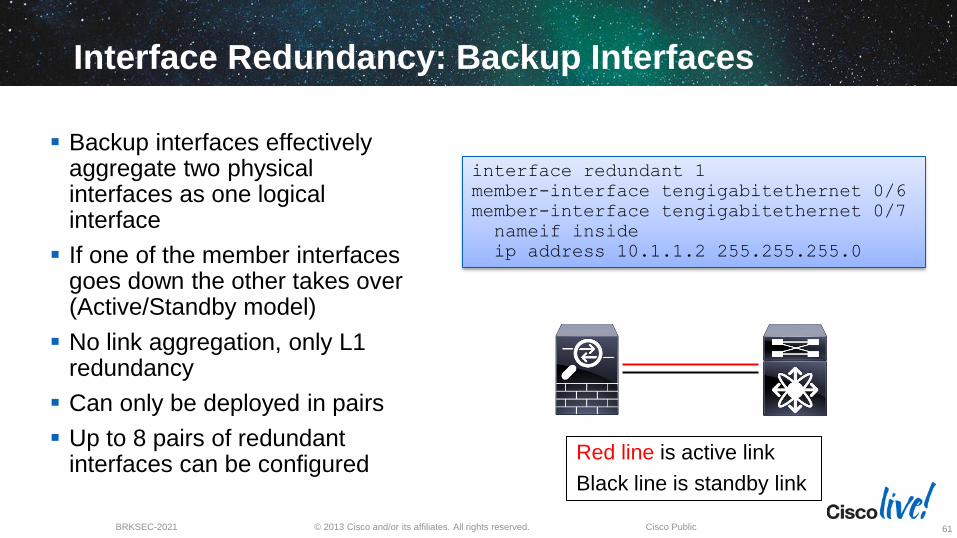
Interface Redundancy: Backup Interfaces
61
Backup interfaces effectively aggregate two physical interfaces as one logical interface
If one of the member interfaces goes down the other takes over (Active/Standby model)
No link aggregation, only L1 redundancy
Can only be deployed in pairs
Up to 8 pairs of redundant interfaces can be configured
interface redundant 1
member-interface tengigabitethernet 0/6
member-interface tengigabitethernet 0/7
nameif inside
ip address 10.1.1.2 255.255.255.0
Red line is active link
Black line is standby link

© 2013 Cisco and/or its affiliates. All rights reserved. BRKSEC-2021 Cisco Public
Interface Redundancy: Port Channels
62
Port channel support was added to the ASA in 8.4 (2011)
Best practice: Utilize Link Aggregation Control Protocol (LACP) where possible
LACP dynamically adds and removes (if necessary) links to the port channel bundle
Up to 8 active links and 8 standby links are supported in the channel
Link aggregation benefit
Best practice in the DC is to use Virtual Port Channels
interface TenGigabitEthernet0/8
channel-group 40 mode active
no nameif
no security-level
!
interface TenGigabitEthernet0/9
channel-group 40 mode active
no nameif
no security-level
!
interface Port-channel40
nameif inside
ip add 10.1.1.2 255.255.255.0
Actively negotiate LACP with switch

© 2013 Cisco and/or its affiliates. All rights reserved. BRKSEC-2021 Cisco Public
‘Show port-channel summary' on ASA
Flags: D – down P - bundled in port-channel
I - stand-alone s – suspended
H - Hot-standby (LACP only) U - in use N - not in use, no aggregation/nameif M - not in use, no aggregation due to minimum links not met
w - waiting to be aggregated
Number of channel-groups in use: 1
Group Port-channel Protocol Span-cluster Ports
------+-------------+---------+------------+---------------------------
40 Po40(U) LACP No Te0/8(P) Te0/9(P)
63
© 2013 Cisco and/or its affiliates. All rights reserved. BRKSEC-2021 Cisco Public
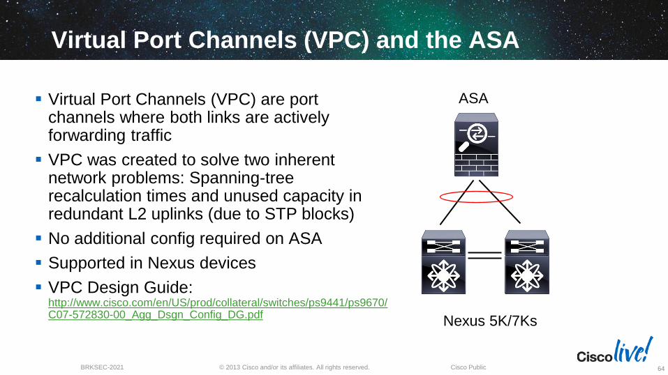
Virtual Port Channels (VPC) and the ASA
64
Virtual Port Channels (VPC) are port channels where both links are actively forwarding traffic
VPC was created to solve two inherent network problems: Spanning-tree recalculation times and unused capacity in redundant L2 uplinks (due to STP blocks)
No additional config required on ASA
Supported in Nexus devices
VPC Design Guide: http://www.cisco.com/en/US/prod/collateral/switches/ps9441/ps9670/C07-572830-00_Agg_Dsgn_Config_DG.pdf
Nexus 5K/7Ks
ASA

© 2013 Cisco and/or its affiliates. All rights reserved. BRKSEC-2021 Cisco Public
Port Channel Options and Summary
VPC PEER LINK
No Port Channel:
STP Allows only one active link
Sub-optimal flows and resource
usage
Single-Chassis LACP Port Channel:
Both links active but no device
redundancy (single switch)
vPC Multi-Chassis LACP Port Channel:
Both links active, optimal redundancy,
all links active
65
ASA CLUSTERING

© 2013 Cisco and/or its affiliates. All rights reserved. BRKSEC-2021 Cisco Public
Introducing ASA Clustering
ASA Clustering is a new feature that was introduced in the 9.0 release (October 2012)
Allows for N+1 redundancy with a backup firewall for every active flow
Clustering is only supported today on the 5580 and 5585 models and requires an additional license (ASA SM later this year)
Clustering data plane is only supported with Nexus 7K 5.2.(5)+ and 6.1.(1)+ and Catalyst 6500 12.2(33)SXI7, SXI8, and SXI9
Clustering control plane is supported on any switch
67
© 2013 Cisco and/or its affiliates. All rights reserved. BRKSEC-2021 Cisco Public
ASA Clustering Design Guidelines
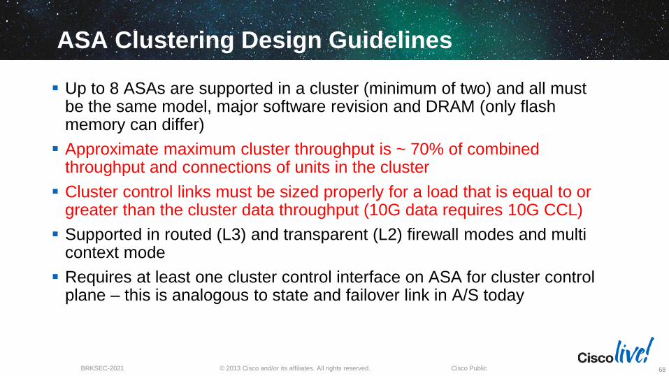
Up to 8 ASAs are supported in a cluster (minimum of two) and all must be the same model, major software revision and DRAM (only flash memory can differ)
Approximate maximum cluster throughput is ~ 70% of combined throughput and connections of units in the cluster
Cluster control links must be sized properly for a load that is equal to or greater than the cluster data throughput (10G data requires 10G CCL)
Supported in routed (L3) and transparent (L2) firewall modes and multi context mode
Requires at least one cluster control interface on ASA for cluster control plane – this is analogous to state and failover link in A/S today
68

© 2013 Cisco and/or its affiliates. All rights reserved. BRKSEC-2021 Cisco Public
Clustering Best Practices – Control Plane
69
Cluster control links must be sized accordingly (e.g.10GE interfaces)
Recommended to use a local port-channel on each ASA for link redundancy and aggregation
Do NOT use a spanned port-channel for cluster control links
Could also use ASA interface redundancy which supports up to 8 pairs of interfaces in an active-passive mode
Manag
em
ent
Netw
ork
Cluster Control
Links
M0/
0
M0/
0
M0/
0
M0/
0
© 2013 Cisco and/or its affiliates. All rights reserved. BRKSEC-2021 Cisco Public
Clustering Best Practices – Cat 6K Data Plane
70
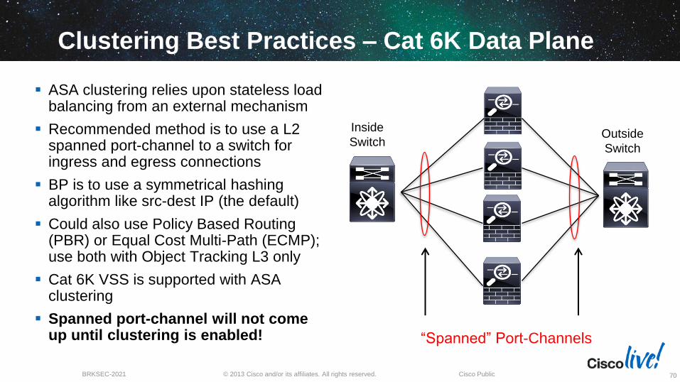
Inside
Switch Outside
Switch
ASA clustering relies upon stateless load balancing from an external mechanism
Recommended method is to use a L2 spanned port-channel to a switch for ingress and egress connections
BP is to use a symmetrical hashing algorithm like src-dest IP (the default)
Could also use Policy Based Routing (PBR) or Equal Cost Multi-Path (ECMP); use both with Object Tracking L3 only
Cat 6K VSS is supported with ASA clustering
Spanned port-channel will not come up until clustering is enabled! “Spanned” Port-Channels

© 2013 Cisco and/or its affiliates. All rights reserved. BRKSEC-2021 Cisco Public
Clustering Best Practices – Nexus 7K Data Plane
71
Nexus 7K
Nexus 7K data center offers advantages with clustering due to VPC feature
All ASAs are dual homed to each 7K
VPC ensures that a single link failure will have zero packet loss
Enhancements to LACP such that ASA cluster appears as one logical firewall to rest of network
Port channel provides packet forwarding
ASAs in L2 or L3 mode
Nexus 7K

© 2013 Cisco and/or its affiliates. All rights reserved. BRKSEC-2021 Cisco Public
Basic Clustering Configuration
72
cluster group DC-SEC
key ***** cluster members share the same
local-unit asa1 how the unit is identified
cluster-interface Port-channel40 ip 99.99.99.1 255.255.255.0
priority 1 lower is higher priority (no preempt)
console-replicate
health-check holdtime 3
clacp system-mac auto system-priority 1
enable

© 2013 Cisco and/or its affiliates. All rights reserved. BRKSEC-2021 Cisco Public
Clustering Data Plane Configuration
73
interface TenGigabitEthernet0/6
channel-group 32 mode active vss-id 1
no nameif
no security-level
!
interface TenGigabitEthernet0/7
channel-group 32 mode active vss-id 2
no nameif
no security-level
interface BVI1
ip address 10.101.10.200 255.255.255.0
interface Port-channel 32
port-channel span-cluster vss-load-balance
no nameif
no security-level
!
interface Port-channel32.101
vlan 101
nameif inside
bridge-group 1
interface Port-channel32.102
vlan 102
nameif outside
bridge-group 1

© 2013 Cisco and/or its affiliates. All rights reserved. BRKSEC-2021 Cisco Public
Port-channel Verification
74
asa(cfg-cluster)# sh port-channel summary
Number of channel-groups in use: 2
Group Port-channel Protocol Span-cluster Ports
------+-------------+---------+-----------+------------------------
32 Po32(U) LACP Yes Te0/6(P) Te0/7(P)
40 Po40(U) LACP No Te0/8(P) Te0/9(P)
Port channel 32 is the cluster data plane
Port channel 40 is the cluster control plane—note that the CCL is not a “span-
cluster” port-channel (best practice)
Both are up as noted by the (U) and were negotiated via LACP
Remember the spanned port-channel will not come up until clustering is
enabled

© 2013 Cisco and/or its affiliates. All rights reserved. BRKSEC-2021 Cisco Public
TCP Session: Symmetric Flow
75
Insid
e N
etw
ork
Ou
tsid
e N
etw
ork
Owner
SYN
Client Server
SYN/ACK SYN/ACK
SYN
Member
1. State
update
Director
State replication from Owner to Director, also serves as failover to provide redundancy should Owner fail
Director is selected per connection using consistent hashing algorithm
Director will act as backup should Owner fail

© 2013 Cisco and/or its affiliates. All rights reserved. BRKSEC-2021 Cisco Public
TCP Session: Asymmetric Flow
76
Insid
e N
etw
ork
Ou
tsid
e N
etw
ork
Owner
Director
SYN
Client Server
SYN/ACK
1. State
update
SYN/ACK SYN
Forwarder
2. Who is
Owner? 3. Owner
Location
Forwarder receives packet that it did not originate, queries Director
Packet is forwarded via cluster control link to Owner who then forwards on to originating client and all subsequent packets are forwarded to Owner with no lookup
This step is eliminated if the Owner can be derived via syn-cookies

© 2013 Cisco and/or its affiliates. All rights reserved. BRKSEC-2021 Cisco Public
Unsupported ASA Features with Clustering
SSL and IPSEC remote access VPN (Site to Site VPN is supported)
Legacy VPN load balancing is not supported for S2S VPNs
Botnet Traffic Filter (BTF)
DHCP Client, Server and Relay
Unified Communications features and inspection engines
WCCP
ASA NGFW SSP
Some application inspection features (see Release Notes)
77

© 2013 Cisco and/or its affiliates. All rights reserved. BRKSEC-2021 Cisco Public
ASA Clustering Best Practices Summary
Use spanned port-channels for cluster data plane and local port-channels or interface redundancy for cluster control interfaces
Use ‘prompt cluster-unit state’ to change prompt on firewall (e.g. asa1-master) to simplify operations and troubleshooting
Cluster Master is for configuration replication only, all units are actively processing flows and backing up (forwarding) flows
Size the cluster control link(s) to equal the largest data interfaces
L3 cluster deployments will have unique L3 interfaces while L2 cluster deployments all interfaces will be the same
78
© 2013 Cisco and/or its affiliates. All rights reserved. BRKSEC-2021 Cisco Public
Virtual Firewalls and High Availability
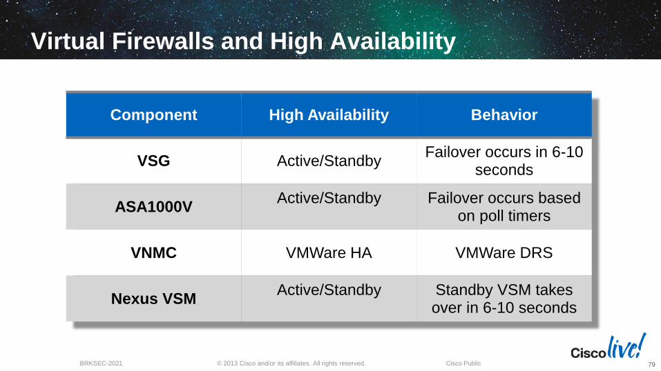
Component High Availability Behavior
VSG Active/Standby Failover occurs in 6-10
seconds
ASA1000V Active/Standby
Failover occurs based
on poll timers
VNMC VMWare HA VMWare DRS
Nexus VSM Active/Standby
Standby VSM takes over in 6-10 seconds
79

NETFLOW SECURITY EVENT LOGGING

© 2013 Cisco and/or its affiliates. All rights reserved. BRKSEC-2021 Cisco Public
NetFlow and Syslog for Visibility
Syslog has been around forever, still has value
Latest ASA syslog (9.1) Events Guide is 666 pages!
Debug level syslog is a great way to DoS your syslog servers
8.2 code release (2010) introduced NetFlow v9 export option
ASA NetFlow is called NSEL (NetFlow Secure Event Logging)
NSEL is different than traditional NetFlow export in that the exports are not “sampled”
81
© 2013 Cisco and/or its affiliates. All rights reserved. BRKSEC-2021 Cisco Public
Syslog vs NetFlow on ASA
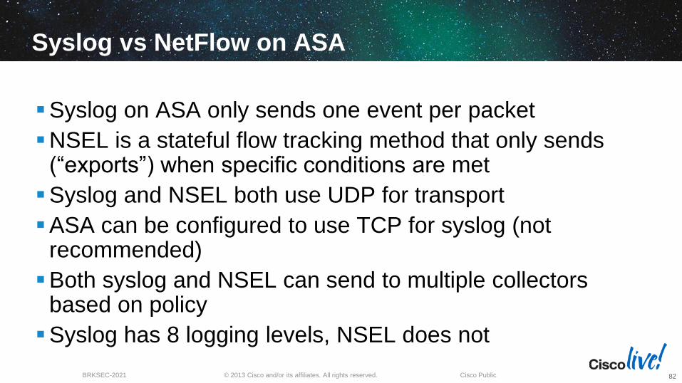
Syslog on ASA only sends one event per packet
NSEL is a stateful flow tracking method that only sends (“exports”) when specific conditions are met
Syslog and NSEL both use UDP for transport
ASA can be configured to use TCP for syslog (not recommended)
Both syslog and NSEL can send to multiple collectors based on policy
Syslog has 8 logging levels, NSEL does not
82

© 2013 Cisco and/or its affiliates. All rights reserved. BRKSEC-2021 Cisco Public
NSEL Best Practices
NSEL has three options: Track flows as they are built, torn down, updated or denied
Any or all can be combined into a NSEL export policy
Events are usually time driven like traditional NF but can also be sent on state changes
NSEL supported both IPv4 and IPv6 flows but not conversions (NAT46 or NAT64)
For more information see the ASA Note for Flow Collectors: http://www.cisco.com/en/US/partner/docs/security/asa/asa91/system/netflow/netflow.html
83

© 2013 Cisco and/or its affiliates. All rights reserved. BRKSEC-2021 Cisco Public
NSEL Configuration in CLI
NSEL and syslog have overlapping events so the best practice is to disable the redundant syslog events
Sample NSEL configuration:
84
asa(config)# flow-export destination inside 10.1.1.30 2055
!! Globally Defines the destination for export
asa(config)# policy-map global_policy
asa(config-pmap)# class netflow_class
asa(config-pmap-c)# flow-export event-type all destination 10.1.1.30

© 2013 Cisco and/or its affiliates. All rights reserved. BRKSEC-2021 Cisco Public
NSEL Configuration in ASDM
85
Firewall> Service Policy Rules> Edit

© 2013 Cisco and/or its affiliates. All rights reserved. BRKSEC-2021 Cisco Public
Collection Tools For Visibility
86
In my external lab we use multiple tools from different vendors for visibility
Lancope StealthWatch®, Arbor Peakflow® and Live Action® are a few
My ASAs are combining syslog with NSEL data for more granular flow details

© 2013 Cisco and/or its affiliates. All rights reserved. BRKSEC-2021 Cisco Public
NSEL for Cyber Threat Defense (CTD)
87
StealthWatch FlowCollector
StealthWatch Management
Console
Cisco ISE
Components
Correlate and display flow analysis with Identity information
Provides identity, profiling and context information through Cisco TrustSec solution
ASA NSEL data for deep visibility
Cisco has an OEM relationship with Lancope’s StealthWatch product
Their console interface is used for monitoring, alerting and reporting

© 2013 Cisco and/or its affiliates. All rights reserved. BRKSEC-2021 Cisco Public
Easily Find All Traffic for a Given User
88
User Flow
Table
Device
Type

© 2013 Cisco and/or its affiliates. All rights reserved. BRKSEC-2021 Cisco Public
A Note on Cyber Threat Defense (CTD) and NSEL Flow Action field can provide additional context
State-based NSEL reporting is taken into consideration in StealthWatch’s behavioral
analysis (concern Index points accumulated for Flow Denied events)
NAT stitching deduplicates flow records from ASA and ASR1000
Lack of TCP flags and bi-directional byte and packet counters limit effectiveness of NSEL only in detecting certain threats (ex. SYN Flood); suggested deployment is to use in combination with other NetFlow sources
89
SECURITY GROUP TAGS
© 2013 Cisco and/or its affiliates. All rights reserved. BRKSEC-2021 Cisco Public
Cisco TrustSec and Security Group Tags
Cisco created an architecture called TrustSec that uses tags in the IP header field to carry information for network based access control
TrustSec is built upon a foundation that traffic is tagged at the edge and network devices enforce a global, consistent access policy throughout the network
These tags are called Security Group Tags (SGT)
ASA 9.0+ gives the ASA the capability to make policy decision based upon SGTs
91
© 2013 Cisco and/or its affiliates. All rights reserved. BRKSEC-2021 Cisco Public
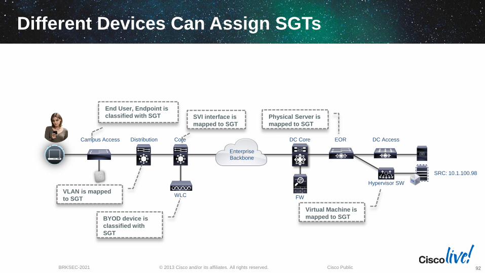
DC Access
WLC FW
Enterprise
Backbone
SRC: 10.1.100.98
Hypervisor SW
Campus Access Distribution Core DC Core EOR
End User, Endpoint is
classified with SGT SVI interface is
mapped to SGT
Physical Server is
mapped to SGT
VLAN is mapped
to SGT
BYOD device is
classified with
SGT
Virtual Machine is
mapped to SGT
Different Devices Can Assign SGTs
92

© 2013 Cisco and/or its affiliates. All rights reserved. BRKSEC-2021 Cisco Public
SGT eXchange Protocol (SXP)
SGTs are supported in hardware
SXP is a mechanism where devices can pull or push IP to SGT mappings from a native SGT device
ASA supports SXP as a listener or a speaker
ISE distributes PAC files to devices in a TrustSec domain
SXP comms are encrypted using the PAC file (RADIUS)
5585-60 supports 100k IP to SGT mappings
93
© 2013 Cisco and/or its affiliates. All rights reserved. BRKSEC-2021 Cisco Public
SGT Mapping
94
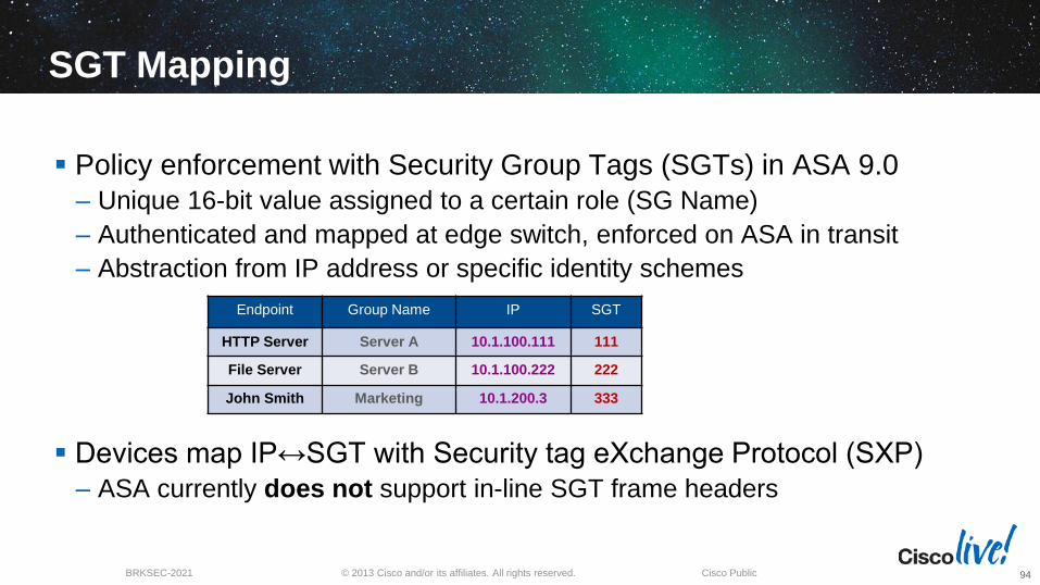
Policy enforcement with Security Group Tags (SGTs) in ASA 9.0
– Unique 16-bit value assigned to a certain role (SG Name)
– Authenticated and mapped at edge switch, enforced on ASA in transit
– Abstraction from IP address or specific identity schemes
Devices map IP↔SGT with Security tag eXchange Protocol (SXP)
– ASA currently does not support in-line SGT frame headers
Endpoint Group Name IP SGT
HTTP Server Server A 10.1.100.111 111
File Server Server B 10.1.100.222 222
John Smith Marketing 10.1.200.3 333

© 2013 Cisco and/or its affiliates. All rights reserved. BRKSEC-2021 Cisco Public
Using Identity and SG ACLs
All entries still require IP information (could be any)
– Identity for source only; SG Tags and Names can be source or destination
– Names must resolve to tags, groups to users, user to IP addresses
Syslogs show Users, Tags and Names when possible
95
access-list IN permit ip security-group name HR_ADMIN host 10.1.1.1 any
access-list IN permit ip user ABCD\John any security-group tag 22 any
From HR_ADMIN
group on 10.1.1.1
To any
destination
From AD user
ABCD/John anywhere
To any IP
with tag 22
%ASA-6-302013: Built outbound TCP connection 16 for outside:198.51.100.100/22
(198.51.100.100/22)(ABCD\Mary, 111:MKTG) to inside:10.0.0.2/20898 (10.0.0.2/20898)(1212)
Slide courtesy of Andrew Ossipov
IPV6

© 2013 Cisco and/or its affiliates. All rights reserved. BRKSEC-2021 Cisco Public
IPv6 and Cisco Firewalls
Virtual Security Gateway supports IPv6
ASA1000V does not support IPv6
ASA code has supported IPv6 for many years and 9.0 release augments IPv6 features (ASA and ASASM)
Very little performance hit with IPv6
AnyConnect IPSEC VPN also support IPv6
ASDM supports IPv6 addresses
NAT46 and 64 support on ASA
97

© 2013 Cisco and/or its affiliates. All rights reserved. BRKSEC-2021 Cisco Public
Unified IPv4 and IPv6 ACLs
Older ASA software used separate IPv4 and IPv6 interface ACLs:
ASA 9.0 and newer uses a single ACL for all IPv4 and IPv6
Configuration migration from earlier releases
– Dual interface ACLs are merged
– Contextual any conversion applies to ACLs only
98
access-list IN extended permit ip host 10.1.1.1 any4
access-list IN extended permit ip host 2001::1 any6
access-list IN extended permit ip host 10.1.1.1 host 2001:DB8::10
access-list IN extended permit ip any any
Any IPv4
Any IPv6
Any IPv4 or IPv6
Mixed IPv4 and IPv6
(Need NAT)
access-list INSIDE_IPV4 extended permit ip host 10.1.1.1 any
ipv6 access-list INSIDE_IPV6 permit ip host 2001:DB8:1 any
access-group INSIDE_IPV4 in interface inside
access-group INSIDE_IPV6 in interface inside
“Any” depends on
the ACL type
Slide courtesy of Andrew Ossipov

© 2013 Cisco and/or its affiliates. All rights reserved. BRKSEC-2021 Cisco Public
ASA IPv6 Best Practices
ipv6 access-list outsideACL permit icmp6 host fe80::21e:7bff:fe10:10c any router-advertisement
ipv6 access-list outsideACL deny icmp6 any any router-advertisement
access-group outsideACL in interface outside
interface vlan2
nameif outside
security-level 0
ipv6 address autoconfig
ipv6 enable
99
ACL to block unknown Router Advertisement (RA)
Suppress ASA interface Router Advertisements
interface vlan2
ipv6 nd suppress-ra
https://supportforums.cisco.com/docs/DOC-15973

© 2013 Cisco and/or its affiliates. All rights reserved. BRKSEC-2021 Cisco Public
Summary and Conclusions
Physical firewalls and virtual firewalls are complementary solutions
Virtualized firewalls (multi context mode) provide a nice option for segmented networks (VRF Lite, MPLS, etc) and/or decentralized management
Firewall clustering offers advantages over the traditional A/S model
NSEL provides additional flow visibility over syslog events
ASA policy can be built with user and group identity
Security Group Tags offer an alternative scalable approach to network access control
The ASA has robust IPv6 capabilities
100

© 2013 Cisco and/or its affiliates. All rights reserved. BRKSEC-2021 Cisco Public
Maximize your Cisco Live experience with your
free Cisco Live 365 account. Download session
PDFs, view sessions on-demand and participate in
live activities throughout the year. Click the Enter
Cisco Live 365 button in your Cisco Live portal to
log in.
Complete Your Online Session Evaluation
Give us your feedback and you could win fabulous prizes. Winners announced daily.
Receive 20 Cisco Daily Challenge points for each session evaluation you complete.
Complete your session evaluation online now through either the mobile app or internet kiosk stations.
101

© 2013 Cisco and/or its affiliates. All rights reserved. BRKSEC-2021 Cisco Public
Reference Links
VPC Design Guide: http://www.cisco.com/en/US/prod/collateral/switches/ps9441/ps9670/C07-572830-
00_Agg_Dsgn_Config_DG.pdf
Virtual Multi-Tenant Data Center (2013) (VMDC) 3.01 Validated Design http://www.cisco.com/en/US/partner/docs/solutions/Enterprise/Data_Center/VMDC/3.0.1/DG/VMDC_3.0.1_DG.html
Virtual Security Gateway (VSG) Deployment Guide http://www.cisco.com/en/US/prod/collateral/modules/ps2706/ps11208/deployment_guide_c07-647435.html
TrustSec 2.0 Design and Implementation Guide http://www.cisco.com/en/US/partner/solutions/ns340/ns414/ns742/ns744/landing_DesignZone_TrustSec.html
TAC Security Podcast http://www.cisco.com/en/US/solutions/ns170/tac/security_tac_podcasts.html
ASA IPv6 Config Guide http://www.cisco.com/en/US/docs/security/asa/asa90/configuration/guide/route_ipv6_neighbor.html
102


Additional Slides

IDENTITY FIREWALL

© 2013 Cisco and/or its affiliates. All rights reserved. BRKSEC-2021 Cisco Public
Why Use Identity on the Firewall?
Access control via traditional means of IP address don’t provide granularity for mobile users
User and group based controls allow us to more easily align security policy with user workloads
Identity is a pillar of visibility and knowing who is on the network
Logging events can include user and group information
ASA captures identity via VPN, auth proxy, or passive authentication methods
106

© 2013 Cisco and/or its affiliates. All rights reserved. BRKSEC-2021 Cisco Public
ASA Identity Firewall
ASA 8.4(2)+ introduced identity firewall for Active Directory and LDAP users
ASA converts username and group information into IP addresses
AD Agent is the older CLI method (now deprecated)
Context Directory Agent (CDA) is a Linux virtual machine with a GUI similar to Cisco’s Identity Services Engine (ISE) and a simple IOS-like interface
107

© 2013 Cisco and/or its affiliates. All rights reserved. BRKSEC-2021 Cisco Public
ASA IDFW Operation
4. John logs into
AD Domain ABCD
10.1.200.3
John Smith
2. Subscribe to user
login events via WMI
Context Directory
Agent (CDA) Active
Directory
Source Destination Action
ABCD\Marketing
192.168.1.200 Allow
Any Any Deny
10.1.200.3
1. Pull AD Group
membership data
3. Receive and update
user to IP mappings
ABCD\JohnSmith
192.168.1.200
5. ABCD\JohnSmith
logged in from 10.1.200.3
IP Packet 6. Policy lookup
and enforcement
108

© 2013 Cisco and/or its affiliates. All rights reserved. BRKSEC-2021 Cisco Public
Screenshot of IDFW
109

© 2013 Cisco and/or its affiliates. All rights reserved. BRKSEC-2021 Cisco Public
Context Directory Agent
110

© 2013 Cisco and/or its affiliates. All rights reserved. BRKSEC-2021 Cisco Public
Cisco CDA – Best Practices and Gotchas
Verify that time is synced between ASA, AD and CDA (NTP)
CDA pulls from Windows Security log, will not work with logs being aggregated from multiple AD servers
Multiple concurrent logins from the same IP are not supported
CDA has no failover mechanism, however, multiple CDA vms can be configured for redundancy
CDA patch 1 release allows use of non-domain users
CDA can support up to 80 domain controller machines, and can internally cache up to 64,000 IP-to-user-identity mappings
More details in the CDA Configuration Guide: http://www.cisco.com/en/US/docs/security/ibf/cda_10/Install_Config_guide/cda10.html
111

© 2013 Cisco and/or its affiliates. All rights reserved. BRKSEC-2021 Cisco Public
Context Directory Agent - Download
112
CDA can be found under “Software on Chassis” for the ASA models