fire pump controller · model mp300 across-the-line start microprocessor electric motor fire pump...
TRANSCRIPT
Fire Pump Controller For Electric Motor Driven Fire Pumps
MP300 Fire Pump Controller
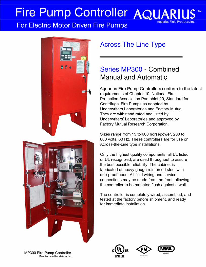
Across The Line Type Series MP300 − Combined Manual and Automatic
Aquarius Fire Pump Controllers conform to the latest requirements of Chapter 10, National Fire Protection Association Pamphlet 20, Standard for Centrifugal Fire Pumps as adopted by Underwriters Laboratories and Factory Mutual. They are withstand rated and listed by Underwriters’ Laboratories and approved by Factory Mutual Research Corporation.
Sizes range from 15 to 600 horsepower, 200 to 600 volts, 60 Hz. These controllers are for use on Across-the-Line type installations.
Only the highest quality components, all UL listed or UL recognized, are used throughout to assure the best possible reliability. The cabinet is fabricated of heavy gauge reinforced steel with drip-proof hood. All field wiring and service connections may be made from the front, allowing the controller to be mounted flush against a wall.
The controller is completely wired, assembled, and tested at the factory before shipment, and ready for immediate installation.
TM
Aquarius Fluid Products, Inc.
Manufactured by Metron, Inc.
Standard and Optional Features
All photographs and graphics are typical and may not represent actual product supplied
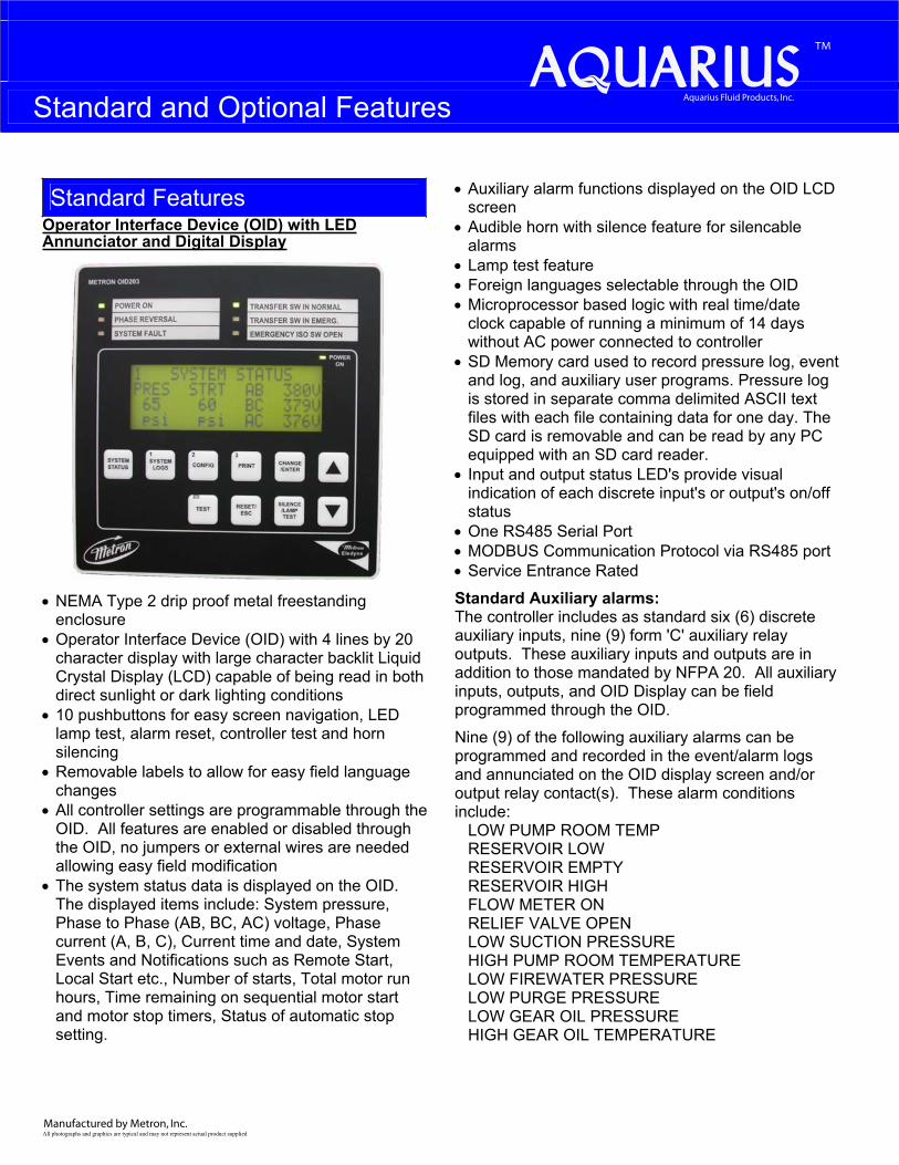
Standard Features Operator Interface Device (OID) with LED Annunciator and Digital Display
• NEMA Type 2 drip proof metal freestanding enclosure
• Operator Interface Device (OID) with 4 lines by 20 character display with large character backlit Liquid Crystal Display (LCD) capable of being read in both direct sunlight or dark lighting conditions
• 10 pushbuttons for easy screen navigation, LED lamp test, alarm reset, controller test and horn silencing
• Removable labels to allow for easy field language changes
• All controller settings are programmable through the OID. All features are enabled or disabled through the OID, no jumpers or external wires are needed allowing easy field modification
• The system status data is displayed on the OID. The displayed items include: System pressure, Phase to Phase (AB, BC, AC) voltage, Phase current (A, B, C), Current time and date, System Events and Notifications such as Remote Start, Local Start etc., Number of starts, Total motor run hours, Time remaining on sequential motor start and motor stop timers, Status of automatic stop setting.
• Auxiliary alarm functions displayed on the OID LCD screen
• Audible horn with silence feature for silencable alarms
• Lamp test feature • Foreign languages selectable through the OID • Microprocessor based logic with real time/date
clock capable of running a minimum of 14 days without AC power connected to controller
• SD Memory card used to record pressure log, event and log, and auxiliary user programs. Pressure log is stored in separate comma delimited ASCII text files with each file containing data for one day. The SD card is removable and can be read by any PC equipped with an SD card reader.
• Input and output status LED's provide visual indication of each discrete input's or output's on/off status
• One RS485 Serial Port• MODBUS Communication Protocol via RS485 port • Service Entrance Rated
Standard Auxiliary alarms: The controller includes as standard six (6) discrete auxiliary inputs, nine (9) form 'C' auxiliary relay outputs. These auxiliary inputs and outputs are in addition to those mandated by NFPA 20. All auxiliary inputs, outputs, and OID Display can be field programmed through the OID.
Nine (9) of the following auxiliary alarms can be programmed and recorded in the event/alarm logs and annunciated on the OID display screen and/or output relay contact(s). These alarm conditions include:
LOW PUMP ROOM TEMP RESERVOIR LOW RESERVOIR EMPTY RESERVOIR HIGH FLOW METER ON RELIEF VALVE OPEN LOW SUCTION PRESSURE HIGH PUMP ROOM TEMPERATURE LOW FIREWATER PRESSURE LOW PURGE PRESSURELOW GEAR OIL PRESSURE HIGH GEAR OIL TEMPERATURE
TM
Aquarius Fluid Products, Inc.
Manufactured by Metron, Inc.
GAS DETECTION HIGH VIBRATION EMERGENCY POWER ON PUMP ROOM DOOR OPEN
Data logging:The controller includes two (2) separate data logs for storing system data that is readable through the OID or copied to a computer equipped with an SD card reader. The 2 data logs are as follows:
Pressure Log: The pressure log provides a continuous pressure record for 30 days. The pressure log samples shall be time and date stamped and stored in permanent non-volatile SD memory card. The pressure log can be searched by each sample, by minute, or by hour through the OID.
Event Log: The event log will store up to 300 of the most current events. These events can include, but is not limited to, any of the following events/alarms:
PUMP RUNNING POWER AVAILABLE PHASE REVERSAL MOTOR OVERLOAD REMOTE START LOCAL START PUMP ON DEMAND SYSTEM FAULT PRESSURE TRANSDUCER FAULT PUMP FAILED TO START LOW INTAKE SHUTDOWN ALARM SUPERVISORY POWER FAILURE LOW PRESSURE AUTO WEEKLY TEST START UNDER FREQUENCY OVER FREQUENCY LOW ZONE / HIGH ZONE CONTACTS HIGH DISCHARGE PRESSURE NO LOAD CONDITION
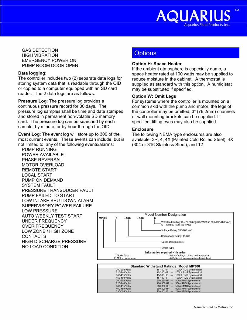
OptionsOption H: Space Heater If the ambient atmosphere is especially damp, a space heater rated at 100 watts may be supplied to reduce moisture in the cabinet. A thermostat is supplied as standard with this option. A humidistat may be substituted if specified. Option W: Omit Legs For systems where the controller is mounted on a common skid with the pump and motor, the legs of the controller may be omitted, 3” (76.2mm) channels or wall mounting brackets can be supplied. If specified, lifting eyes may also be supplied.
EnclosureThe following NEMA type enclosures are also available: 3R, 4, 4X (Painted Cold Rolled Steel), 4X (304 or 316 Stainless Steel), and 12
Manufactured by Metron, Inc.
TM
Aquarius Fluid Products, Inc.
Fire Pump Controller For Electric Motor Driven Fire Pumps
_____________________________________________________________________________________________________________ Aquarius Fluid Products, Inc. • 2585 Millennium Drive, Unit B • Elgin, IL 60124 • (800) 208.8181 • Fax (847) 289.9292 • www.aquariusfp.com
Bulletin MP300 05/10vØ
Model MP300 Across-the-line Start Microprocessor Electric Motor Fire Pump Controller
SpecificationsGeneral Controller Description
The Fire Pump Controller shall be factory
assembled, wired and tested as a unit and shall
conform to all requirements of the latest edition
of NFPA 20, NFPA 70 and be Third Party Listed
by Underwriters Laboratories (UL) and
Approved by Factory Mutual (FM). The
controller shall be available for 208, 230, 380-
415, or 480 volt three phase power.
Controller Equipment Features
The controller shall include the following
standard features:
• NEMA Type 2 drip proof metal freestanding
enclosure
• Operator Interface Device (OID) with 4 lines
by 20 character display with large character
backlit LCD capable of being read in both
direct sunlight or dark lighting conditions
• 10 pushbuttons for easy screen navigation,
system test, lamp test, alarm reset, and horn
silencing
• Multicolored LED's for alarm and mode
annunciation
• LEDs shall be labeled with removable labels
to allow for easy field modification of
language changes
• All controller settings shall be programmable
through the OID and shall be protected by two
password levels
• All features shall be enabled or disabled
through the OID, no jumpers or external wires
shall be needed or allowed to activate or de-
activate a feature
• The system status data shall be displayed on
the OID. The displayed items shall include:
System pressure, Phase to Phase (AB, BC,
AC) voltage, Phase current (A, B, C), System
Events and Notifications, Current time and
date, Number of starts, Total motor run hours,
Displayed countdown timers for: Sequential
motor start and motor stop, Status of
Automatic Stop Setting.
• Audible horn with silence feature for
silencable alarms
• Lamp test feature
• Foreign languages selectable through the OID
• Microprocessor based logic with real time/date
clock capable of running a minimum of 14
days without AC power connected to
controller and non-volatile flash memory to
permanently store the continuous pressure log,
event log, alarm log and all user changeable
set points and system data. Battery backup of
any kind not allowed.
• Input and output status LED's to provide visual
indication of each discrete input's or output's
on/off status
• One RS485 Serial Port
• MODBUS Communication Protocol via
RS485 port
• All wiring terminals on PCB's shall be
removable type
• Service Entrance Rated
Auxiliary alarms
As standard the controller shall include 6 discrete
auxiliary inputs, 9 form 'C' auxiliary relay
outputs. These auxiliary inputs and outputs are
in addition to those mandated by NFPA 20. All
auxiliary inputs, outputs, and OID screens shall
be field programmable through the OID. This
permits a multitude of customizable controller
configurations to meet each installations unique
needs without adding cost to the controller. The
use of jumpers, soldering, or other external
components are not allowed.
The user can select any 9 of the following
auxiliary alarms that can be programmed and
recorded in the event log and annunciated with
an OID screen and output relay contact for
conditions such as but not limited to:
LOW PUMP ROOM TEMP RESERVOIR LOW RESERVOIR EMPTY RESERVOIR HIGH FLOW METER ON RELIEF VALVE OPEN LOW SUCTION PRESSURE HIGH PUMP ROOM TEMPERATURE LOW FIREWATER PRESSURE LOW PURGE PRESSURE LOW GEAR OIL PRESSURE HIGH GEAR OIL TEMPERATURE GAS DETECTION HIGH VIBRATION EMERGENCY POWER ONPUMP ROOM DOOR OPEN
Data logging
The controller shall have separate data logs for
storing system data that is readable through the
OID.
Pressure Log: The controller shall have a
Pressure log with continuous pressure recording
of 30 days of data. The pressure log samples
shall be time and date stamped and stored on a
removable SD card memory. The pressure log
shall be searchable by each sample, by minute, or
by hour. Each days entries shall be stored in a
separate file on the SD card. SD memory shall be
readable by any PC equipped with an SD
memory card reader.
Event Log: The event log shall be capable of
storing no less than 3000 events. These events
shall include, but is not limited to, any of the
following events/alarms:
PUMP RUNNING POWER AVAILABLE PHASE REVERSAL MOTOR OVERLOAD REMOTE START LOCAL START PUMP ON DEMAND SYSTEM FAULT PRESSURE TRANSDUCER FAULT PUMP FAILED TO START LOW INTAKE SHUTDOWN ALARM SUPERVISORY POWER FAILURE LOW PRESSURE AUTO WEEKLY TEST START UNDER FREQUENCY OVER FREQUENCY LOW ZONE / HIGH ZONE CONTACTS HIGH DISCHARGE PRESSURE NO LOAD CONDITION
Each event or alarm recorded in the event log
shall have the following data recorded with the
event/alarm:
• Time and Date of Event or Alarm
• System Pressure
• Descriptive Text Message of the Event/Alarm
• Motor Running Status
• Phase to Phase Volts
• Phase Amps
The internal logic of the controller shall be
capable of operation in a temperature range of
4.4ºC to 40ºC and high, non-condensing,
humidity levels.
The controller shall be manufactured by Metron.
TM
Aquarius Fluid Products, Inc.
Fire Pump Controller For Electric Motor Driven Fire Pumps
MP700 Fire Pump Controller
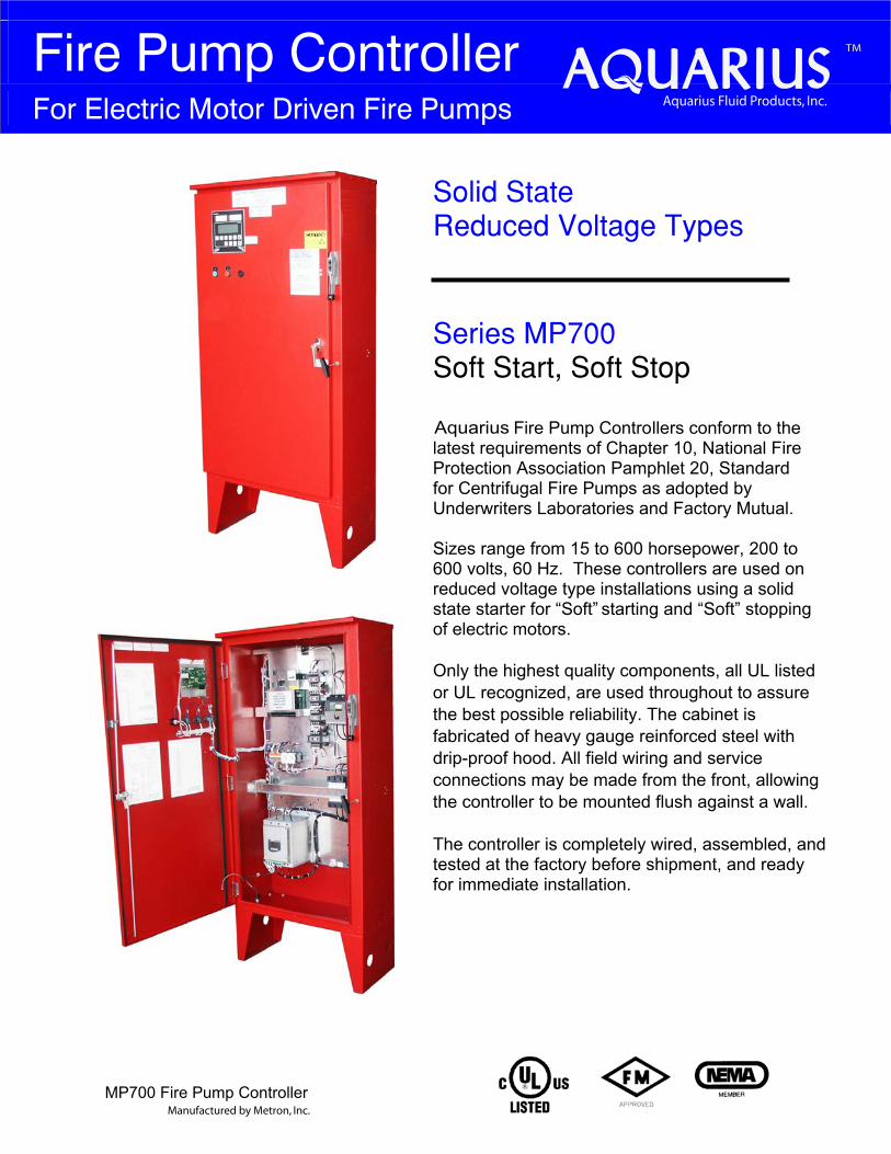
Solid State Reduced Voltage Types Series MP700 Soft Start, Soft Stop
Fire Pump Controllers conform to the latest requirements of Chapter 10, National Fire Protection Association Pamphlet 20, Standard for Centrifugal Fire Pumps as adopted by Underwriters Laboratories and Factory Mutual.
Sizes range from 15 to 600 horsepower, 200 to 600 volts, 60 Hz. These controllers are used on reduced voltage type installations using a solid state starter for “Soft” starting and “Soft” stopping of electric motors.
Only the highest quality components, all UL listed or UL recognized, are used throughout to assure the best possible reliability. The cabinet is fabricated of heavy gauge reinforced steel with drip-proof hood. All field wiring and service connections may be made from the front, allowing the controller to be mounted flush against a wall.
The controller is completely wired, assembled, and tested at the factory before shipment, and ready for immediate installation.
TM
Aquarius Fluid Products, Inc.
Manufactured by Metron, Inc.
Aquarius
Standard and Optional Features
All photographs and graphics are typical and may not represent actual product supplied
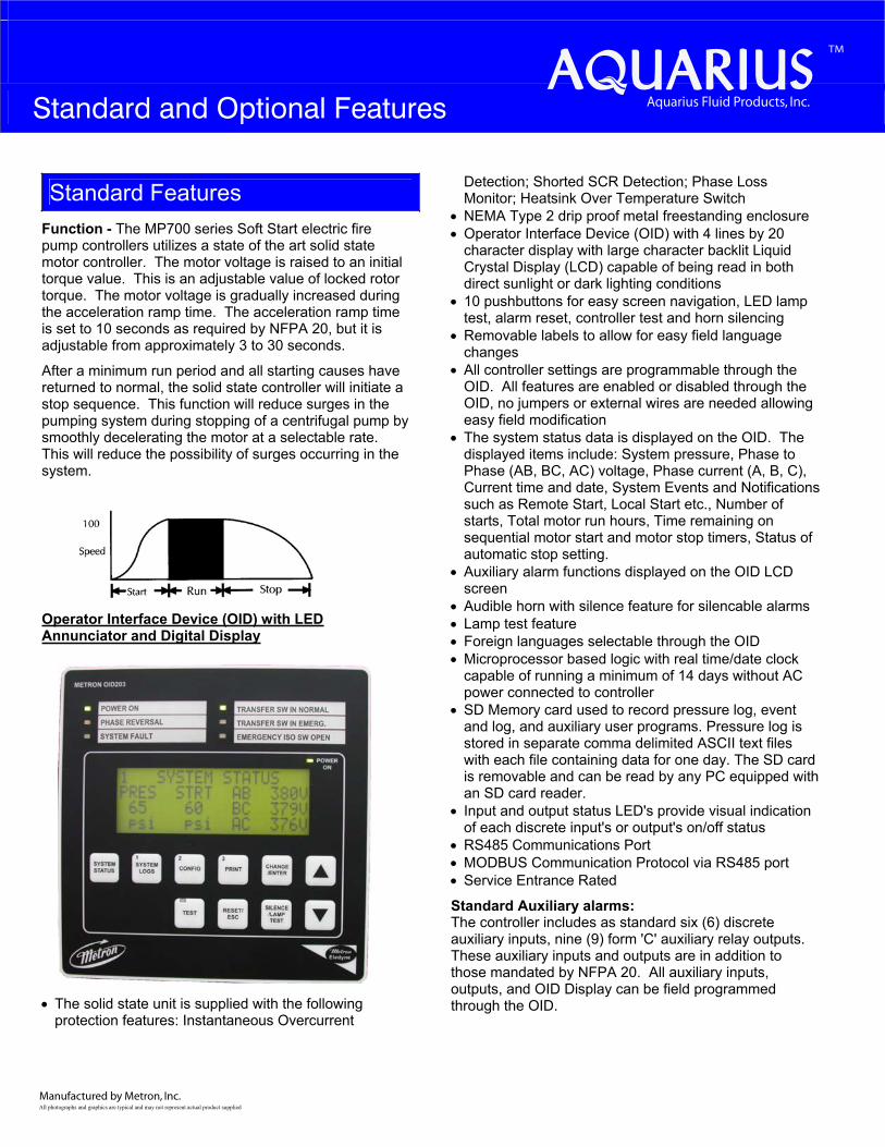
Standard Features Function - The MP700 series Soft Start electric fire pump controllers utilizes a state of the art solid state motor controller. The motor voltage is raised to an initial torque value. This is an adjustable value of locked rotor torque. The motor voltage is gradually increased during the acceleration ramp time. The acceleration ramp time is set to 10 seconds as required by NFPA 20, but it is adjustable from approximately 3 to 30 seconds.
After a minimum run period and all starting causes have returned to normal, the solid state controller will initiate a stop sequence. This function will reduce surges in the pumping system during stopping of a centrifugal pump by smoothly decelerating the motor at a selectable rate. This will reduce the possibility of surges occurring in the system.
Operator Interface Device (OID) with LED Annunciator and Digital Display
• The solid state unit is supplied with the following protection features: Instantaneous Overcurrent
Detection; Shorted SCR Detection; Phase Loss Monitor; Heatsink Over Temperature Switch
• NEMA Type 2 drip proof metal freestanding enclosure • Operator Interface Device (OID) with 4 lines by 20
character display with large character backlit Liquid Crystal Display (LCD) capable of being read in both direct sunlight or dark lighting conditions
• 10 pushbuttons for easy screen navigation, LED lamp test, alarm reset, controller test and horn silencing
• Removable labels to allow for easy field language changes
• All controller settings are programmable through the OID. All features are enabled or disabled through the OID, no jumpers or external wires are needed allowing easy field modification
• The system status data is displayed on the OID. The displayed items include: System pressure, Phase to Phase (AB, BC, AC) voltage, Phase current (A, B, C), Current time and date, System Events and Notifications such as Remote Start, Local Start etc., Number of starts, Total motor run hours, Time remaining on sequential motor start and motor stop timers, Status of automatic stop setting.
• Auxiliary alarm functions displayed on the OID LCD screen
• Audible horn with silence feature for silencable alarms • Lamp test feature • Foreign languages selectable through the OID • Microprocessor based logic with real time/date clock
capable of running a minimum of 14 days without AC power connected to controller
• SD Memory card used to record pressure log, event and log, and auxiliary user programs. Pressure log is stored in separate comma delimited ASCII text files with each file containing data for one day. The SD card is removable and can be read by any PC equipped with an SD card reader.
• Input and output status LED's provide visual indication of each discrete input's or output's on/off status
• RS485 Communications Port • MODBUS Communication Protocol via RS485 port • Service Entrance Rated
Standard Auxiliary alarms: The controller includes as standard six (6) discrete auxiliary inputs, nine (9) form 'C' auxiliary relay outputs. These auxiliary inputs and outputs are in addition to those mandated by NFPA 20. All auxiliary inputs, outputs, and OID Display can be field programmed through the OID.
TM
Aquarius Fluid Products, Inc.
Manufactured by Metron, Inc.

Nine (9) of the following auxiliary alarms can be programmed and recorded in the event/alarm logs and annunciated on the OID display screen and/or output relay contact(s). These alarm conditions include:
LOW PUMP ROOM TEMP RESERVOIR LOW RESERVOIR EMPTY RESERVOIR HIGH FLOW METER ON RELIEF VALVE OPEN LOW SUCTION PRESSURE HIGH PUMP ROOM TEMPERATURE LOW FIREWATER PRESSURE LOW PURGE PRESSURE LOW GEAR OIL PRESSURE HIGH GEAR OIL TEMPERATURE GAS DETECTION HIGH VIBRATION EMERGENCY POWER ONPUMP ROOM DOOR OPEN
Data logging: The controller includes two (2) separate data logs for storing system data that is readable through the OID or copied to a computer equipped with an SD card reader. The 2 data logs are as follows:
Pressure Log: The pressure log provides a continuous pressure record for 30 days. The pressure log samples shall be time and date stamped and stored in permanent non-volatile SD memory card. The pressure log can be searched by each sample, by minute, or by hour through the OID.
Event Log: The event log will store up to 300 of the most current events. These events can include, but is not limited to, any of the following events/alarms:
PUMP RUNNING POWER AVAILABLE PHASE REVERSAL MOTOR OVERLOAD REMOTE START LOCAL START PUMP ON DEMAND SYSTEM FAULT PRESSURE TRANSDUCER FAULT PUMP FAILED TO START LOW INTAKE SHUTDOWN ALARM SUPERVISORY POWER FAILURE LOW PRESSURE AUTO WEEKLY TEST START UNDER FREQUENCY OVER FREQUENCY LOW ZONE / HIGH ZONE CONTACTS
HIGH DISCHARGE PRESSURE NO LOAD CONDITION
OptionsOption H: Space Heater If the ambient atmosphere is especially damp, a space heater rated at 100 watts may be supplied to reduce moisture in the cabinet. A thermostat is supplied as standard with this option. A humidistat may be substituted if specified.
Option W: Omit Legs For systems where the controller is mounted on a common skid with the pump and motor, the legs of the controller may be omitted, 3” (76.2mm) channels or wall mounting brackets can be supplied. If specified, lifting eyes may also be supplied.
EnclosureThe following NEMA type enclosures are also available: 3R, 4, 4X (Painted Cold Rolled Steel), 4X (304 or 316 Stainless Steel), and 12
TM
Aquarius Fluid Products, Inc.
Manufactured by Metron, Inc.
Fire Pump Controller For Electric Motor Driven Fire Pumps
_____________________________________________________________________________________________________________
Bulletin MP700 05/10 V Ø
Model MP700 Soft Start/Soft Stop Microprocessor Electric Motor Fire Pump Controller
Specifications
The Fire Pump Controller shall be factory
assembled, wired and tested as a unit and shall
conform to all requirements of the latest edition
of NFPA 20, NFPA 70 and be Third Party
Listed by Underwriters Laboratories (UL) and
Approved by Factory Mutual (FM). The
controller shall be available for 208, 230, 380-
415, or 480 volt three phase power.
Controller Equipment Features
The controller shall include the following
standard features:
• NEMA Type 2 drip proof metal freestanding
enclosure
• The controller shall be designed for Soft Start
starting and shall incorporate a special Pump
Control feature which eliminates excessive
acceleration torque problems (water hammer)
and related effects. The controller shall stop
the motor by reducing the speed in a manner
that prevents any sudden changes in torque
and minimizes surges in the system resulting
in a smooth deceleration to the pump
• Operator Interface Device (OID) with 4 lines
by 20 character display with large character
backlit LCD capable of being read in both
direct sunlight or dark lighting conditions
• 10 pushbuttons for easy screen navigation,
system test, lamp test, alarm reset, and horn
silencing
• Multicolored LED's for alarm and mode
annunciation
• LEDs shall be labeled with removable labels
to allow for easy field modification of
language changes
• All controller settings shall be programmable
through the OID and shall be protected by
two password levels
• All features shall be enabled or disabled
through the OID, no jumpers or external wires
shall be needed or allowed to activate or de-
activate a feature
• The system status data shall be displayed
on the OID. The displayed items shall
include: System pressure, Phase to Phase
(AB, BC, AC) voltage, Phase current (A,
B, C), System Events and Notifications,
Current time and date, Number of starts,
Total motor run hours, Displayed
countdown timers for: Sequential motor
start and motor stop, Status of Automatic
Stop Setting
• Audible horn with silence feature for
silencable alarms
• Lamp test feature
• Foreign languages selectable through the OID
• Microprocessor based logic with real
time/date clock capable of running a
minimum of 14 days without AC power
connected to controller and non-volatile flash
memory to permanently store the continuous
pressure log, event log, alarm log and all user
changeable set points and system data.
Battery backup of any kind not allowed
• Input and output status LED's to provide
visual indication of each discrete input's or
output's on/off status
• RS485 Communications Port
• MODBUS Communication Protocol via
RS485 port
• All wiring terminals on PCB's shall be
removable type
• Service Entrance Rated
Auxiliary alarms As standard the controller shall include 6
discrete auxiliary inputs, 9 form 'C' auxiliary
relay outputs. These auxiliary inputs and
outputs are in addition to those mandated by
NFPA 20. All auxiliary inputs, outputs, and
OID screens shall be field programmable
through the OID. This permits a multitude of
customizable controller configurations to meet
each installations unique needs without adding
cost to the controller. The use of jumpers,
soldering, or other external components are not
allowed.
The user can select any 9 of the following
auxiliary alarms that can be programmed and
recorded in the event log and annunciated with
an OID screen and output relay contact for
conditions such as but not limited to:
LOW PUMP ROOM TEMP RESERVOIR LOW RESERVOIR EMPTY RESERVOIR HIGH FLOW METER ON RELIEF VALVE OPEN LOW SUCTION PRESSURE HIGH PUMP ROOM TEMPERATURE LOW FIREWATER PRESSURE LOW PURGE PRESSURE LOW GEAR OIL PRESSURE HIGH GEAR OIL TEMPERATURE GAS DETECTION HIGH VIBRATION EMERGENCY POWER ONPUMP ROOM DOOR OPEN
Data logging The controller shall have separate data logs for
storing system data that is readable through the
OID.
Pressure Log: The controller shall have a
Pressure log with continuous pressure recording
of 30 days of data. The pressure log samples
shall be time and date stamped and stored on a
removable SD card memory. The pressure log
shall be searchable by each sample, by minute,
or by hour. Each days entries shall be stored in a
separate file on the SD card. SD memory shall
be readable by any PC equipped with an SD
memory card reader.
Event Log: The event log shall be capable of
storing no less than 3000 events. These events
shall include, but is not limited to, any of the
following events/alarms:
PUMP RUNNING POWER AVAILABLE PHASE REVERSAL MOTOR OVERLOAD REMOTE START LOCAL START PUMP ON DEMAND SYSTEM FAULT PRESSURE TRANSDUCER FAULT PUMP FAILED TO START LOW INTAKE SHUTDOWN ALARM SUPERVISORY POWER FAILURE LOW PRESSURE AUTO WEEKLY TEST START UNDER FREQUENCY OVER FREQUENCY LOW ZONE / HIGH ZONE CONTACTS HIGH DISCHARGE PRESSURE NO LOAD CONDITION
Each event or alarm recorded in the event log
shall have the following data recorded with the
event/alarm:
• Time and Date of Event or Alarm
• System Pressure
• Descriptive Text Message of the Event/Alarm
• Motor Running Status
• Phase to Phase Volts
• Phase Amps
The internal logic of the controller shall be
capable of operation in a temperature range of
4.4ºC to 40ºC and high, non-condensing,
humidity levels.
The controller shall be manufactured by Metron.
TM
Aquarius Fluid Products, Inc.
Aquarius Fluid Products, Inc. • 2585 Millennium Drive, Unit B • Elgin, IL 60124 • (800) 208.8181 • Fax (847) 289.9292 • www.aquariusfp.com
Fire Pump Controller For Electric Motor Driven Fire Pumps
MP430 Fire Pump Controller
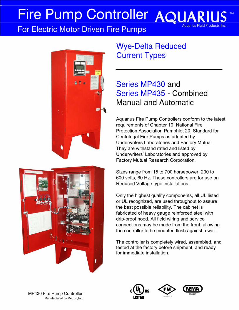
Wye−Delta Reduced Current Types Series MP430 and Series MP435 − CombinedManual and Automatic Aquarius Fire Pump Controllers conform to the latest requirements of Chapter 10, National Fire Protection Association Pamphlet 20, Standard for Centrifugal Fire Pumps as adopted by Underwriters Laboratories and Factory Mutual. They are withstand rated and listed by Underwriters’ Laboratories and approved by Factory Mutual Research Corporation.
Sizes range from 15 to 700 horsepower, 200 to 600 volts, 60 Hz. These controllers are for use on Reduced Voltage type installations.
Only the highest quality components, all UL listed or UL recognized, are used throughout to assure the best possible reliability. The cabinet is fabricated of heavy gauge reinforced steel with drip-proof hood. All field wiring and service connections may be made from the front, allowing the controller to be mounted flush against a wall.
The controller is completely wired, assembled, and tested at the factory before shipment, and ready for immediate installation.
Manufactured by Metron, Inc.
TM
Aquarius Fluid Products, Inc.
Standard and Optional Features
All photographs and graphics are typical and may not represent actual product supplied
Standard Features Series MP430/MP435 Wye- Delta motors have all six leads brought out to the motor terminal box. These leads are connected by the controller first in the Wye configuration which draws only 33% of normal starting current and develops 33% of normal starting torque. After a short time delay, the controller then connects the motor winding in a Delta configuration, applying full voltage and drawing full load running current and developing full running torque.
With the MP430 open transition types, there is a very short period of time where no voltage is applied to the motor during transition from Wye to Delta connections. This condition can cause current surges or disturbances being fed back into the main power source. The magnitude of the surges is proportional to the phase difference between the voltage generated by the running motor and the power source. These transients can in some instances, affect other equipment which are sensitive to current surges.
The MP435 closed transition types provide a smoother transition from Wye to Delta by keeping the motor continuously energized during the transition period. This is accomplished by means of resistors which are connected in the circuit during the momentary period of transition from Wye to Delta.
Metron Wye-Delta Controllers incorporate a mechanical as well as electrical interlock to prevent the Wye connecting contactor from being energized at the same time as the Delta contactor.
An emergency start lever to close starting contactor independent of automatic control circuits. When used, this lever will bypass the reduced current start feature and start the motor with full inrush current drawn from the power source.
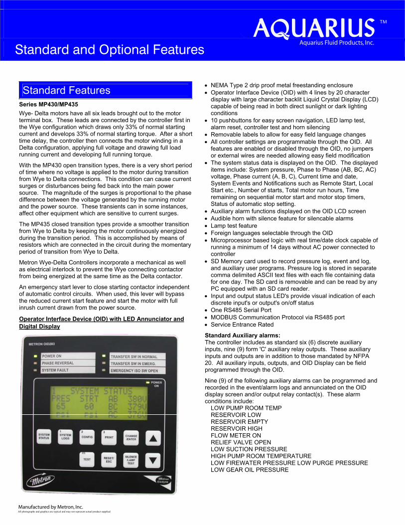
Operator Interface Device (OID) with LED Annunciator and Digital Display
• NEMA Type 2 drip proof metal freestanding enclosure • Operator Interface Device (OID) with 4 lines by 20 character
display with large character backlit Liquid Crystal Display (LCD) capable of being read in both direct sunlight or dark lighting conditions
• 10 pushbuttons for easy screen navigation, LED lamp test, alarm reset, controller test and horn silencing
• Removable labels to allow for easy field language changes • All controller settings are programmable through the OID. All
features are enabled or disabled through the OID, no jumpers or external wires are needed allowing easy field modification
• The system status data is displayed on the OID. The displayed items include: System pressure, Phase to Phase (AB, BC, AC) voltage, Phase current (A, B, C), Current time and date, System Events and Notifications such as Remote Start, Local Start etc., Number of starts, Total motor run hours, Time remaining on sequential motor start and motor stop timers, Status of automatic stop setting.
• Auxiliary alarm functions displayed on the OID LCD screen • Audible horn with silence feature for silencable alarms • Lamp test feature • Foreign languages selectable through the OID • Microprocessor based logic with real time/date clock capable of
running a minimum of 14 days without AC power connected to controller
• SD Memory card used to record pressure log, event and log, and auxiliary user programs. Pressure log is stored in separate comma delimited ASCII text files with each file containing data for one day. The SD card is removable and can be read by any PC equipped with an SD card reader.
• Input and output status LED's provide visual indication of each discrete input's or output's on/off status
• One RS485 Serial Port • MODBUS Communication Protocol via RS485 port • Service Entrance Rated
Standard Auxiliary alarms: The controller includes as standard six (6) discrete auxiliary inputs, nine (9) form 'C' auxiliary relay outputs. These auxiliary inputs and outputs are in addition to those mandated by NFPA 20. All auxiliary inputs, outputs, and OID Display can be field programmed through the OID.
Nine (9) of the following auxiliary alarms can be programmed and recorded in the event/alarm logs and annunciated on the OID display screen and/or output relay contact(s). These alarm conditions include:
LOW PUMP ROOM TEMP RESERVOIR LOW RESERVOIR EMPTY RESERVOIR HIGH FLOW METER ON RELIEF VALVE OPEN LOW SUCTION PRESSURE HIGH PUMP ROOM TEMPERATURE LOW FIREWATER PRESSURE LOW PURGE PRESSURE LOW GEAR OIL PRESSURE
Manufactured by Metron, Inc.
TM
Aquarius Fluid Products, Inc.
HIGH GEAR OIL TEMPERATURE GAS DETECTION HIGH VIBRATION EMERGENCY POWER ONPUMP ROOM DOOR OPEN
Data logging:The controller includes two (2) separate data logs for storing system data that is readable through the OID or copied to a computer equipped with an SD card reader. The 2 data logs are as follows:
Pressure Log: The pressure log provides a continuous pressure record for 30 days. The pressure log samples shall be time and date stamped and stored in permanent non-volatile SD memory card. The pressure log can be searched by each sample, by minute, or by hour through the OID.
Event Log: The event log will store up to 300 of the most current events. These events can include, but is not limited to, any of the following events/alarms:
PUMP RUNNING POWER AVAILABLE PHASE REVERSAL MOTOR OVERLOAD REMOTE START LOCAL START PUMP ON DEMAND SYSTEM FAULT PRESSURE TRANSDUCER FAULT PUMP FAILED TO START LOW INTAKE SHUTDOWN ALARM SUPERVISORY POWER FAILURE LOW PRESSURE AUTO WEEKLY TEST START UNDER FREQUENCY OVER FREQUENCY LOW ZONE / HIGH ZONE CONTACTS HIGH DISCHARGE PRESSURE NO LOAD CONDITION
OptionsOption H: Space Heater If the ambient atmosphere is especially damp, a space heater rated at 100 watts may be supplied to reduce moisture in the cabinet. A thermostat is supplied as standard with this option. A humidistat may be substituted if specified.
Option W: Omit Legs For systems where the controller is mounted on a common skid with the pump and motor, the legs of the controller may be omitted, 3” (76.2mm) channels or wall mounting brackets can be supplied. If specified, lifting eyes may also be supplied.
Enclosure The following NEMA type enclosures are also available: 3R, 4, 4X (Painted Cold Rolled Steel), 4X (304 or 316 Stainless Steel), and 12
TM
Aquarius Fluid Products, Inc.
Manufactured by Metron, Inc.
Fire Pump Controller For Electric Motor Driven Fire Pumps
_____________________________________________________________________________________________________________
Bulletin MP430/MP435 05/10vØ
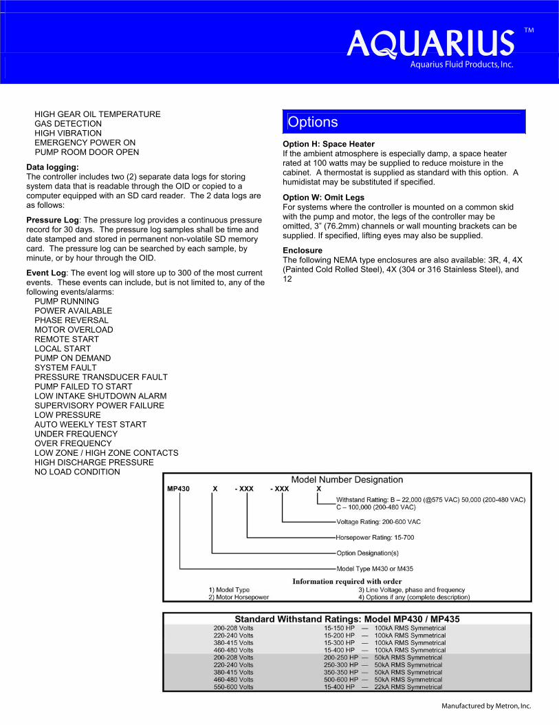
Model MP430/435 Wye-Delta Start Microprocessor Electric Motor Fire Pump Controller
SpecificationsGeneral Controller Description
The Fire Pump Controller shall be factory
assembled, wired and tested as a unit and shall
conform to all requirements of the latest edition
of NFPA 20, NFPA 70 and be Third Party Listed
by Underwriters Laboratories (UL) and
Approved by Factory Mutual (FM). The
controller shall be available for 208, 230, 380-
415, or 480 volt three phase power.
Controller Equipment Features
The controller shall include the following
standard features:
• NEMA Type 2 drip proof metal freestanding
enclosure
• The controller shall be designed for Wye-Delta
starting and shall start the motor in the Wye
configuration drawing 33% of normal current,
then connect the motor in the Delta
configuration applying full voltage.
• Operator Interface Device (OID) with 4 lines
by 20 character display with large character
backlit LCD capable of being read in both
direct sunlight or dark lighting conditions
• 10 pushbuttons for easy screen navigation,
system test, lamp test, alarm reset, and horn
silencing
• Multicolored LED's for alarm and mode
annunciation
• LEDs shall be labeled with removable labels
to allow for easy field modification of
language changes
• All controller settings shall be programmable
through the OID and shall be protected by two
password levels
• All features shall be enabled or disabled
through the OID, no jumpers or external wires
shall be needed or allowed to activate or de-
activate a feature
• The system status data shall be displayed on
the OID. The displayed items shall include:
System pressure, Phase to Phase (AB, BC,
AC) voltage, Phase current (A, B, C), System
Events and Notifications, Current time and
date, Number of starts, Total motor run hours,
Displayed countdown timers for: Sequential
motor start and motor stop, Status of
Automatic Stop Setting.
• Audible horn with silence feature for
silencable alarms
• Lamp test feature
• Foreign languages selectable through the OID
• Microprocessor based logic with real time/date
clock capable of running a minimum of 14
days without AC power connected to
controller and non-volatile flash memory to
permanently store the continuous pressure log,
event log, alarm log and all user changeable
set points and system data. Battery backup of
any kind not allowed.
• Input and output status LED's to provide visual
indication of each discrete input's or output's
on/off status
• One RS485 Serial Port
• MODBUS Communication Protocol via
RS485 port
• All wiring terminals on PCB's shall be
removable type
• Service Entrance Rated
Auxiliary alarms
As standard the controller shall include 6 discrete
auxiliary inputs, 9 form 'C' auxiliary relay
outputs. These auxiliary inputs and outputs are
in addition to those mandated by NFPA 20. All
auxiliary inputs, outputs, and OID screens shall
be field programmable through the OID. This
permits a multitude of customizable controller
configurations to meet each installations unique
needs without adding cost to the controller. The
use of jumpers, soldering, or other external
components are not allowed.
The user can select any 9 of the following
auxiliary alarms that can be programmed and
recorded in the event log and annunciated with
an OID screen and output relay contact for
conditions such as but not limited to:
LOW PUMP ROOM TEMP RESERVOIR LOW RESERVOIR EMPTY RESERVOIR HIGH FLOW METER ON RELIEF VALVE OPEN LOW SUCTION PRESSURE HIGH PUMP ROOM TEMPERATURE LOW FIREWATER PRESSURE LOW PURGE PRESSURE LOW GEAR OIL PRESSURE HIGH GEAR OIL TEMPERATURE GAS DETECTION HIGH VIBRATION EMERGENCY POWER ONPUMP ROOM DOOR OPEN
Data logging The controller shall have separate data logs for
storing system data that is readable through the
OID.
Pressure Log: The controller shall have a
Pressure log with continuous pressure recording
of 30 days of data. The pressure log samples
shall be time and date stamped and stored on a
removable SD card memory. The pressure log
shall be searchable by each sample, by minute, or
by hour. Each days entries shall be stored in a
separate file on the SD card. SD memory shall be
readable by any PC equipped with an SD
memory card reader.
Event Log: The event log shall be capable of
storing no less than 3000 events. These events
shall include, but is not limited to, any of the
following events/alarms:
PUMP RUNNING POWER AVAILABLE PHASE REVERSAL MOTOR OVERLOAD REMOTE START LOCAL START PUMP ON DEMAND SYSTEM FAULT PRESSURE TRANSDUCER FAULT PUMP FAILED TO START LOW INTAKE SHUTDOWN ALARM SUPERVISORY POWER FAILURE LOW PRESSURE AUTO WEEKLY TEST START UNDER FREQUENCY OVER FREQUENCY LOW ZONE / HIGH ZONE CONTACTS HIGH DISCHARGE PRESSURE NO LOAD CONDITION
Each event or alarm recorded in the event log
shall have the following data recorded with the
event/alarm:
• Time and Date of Event or Alarm
• System Pressure
• Descriptive Text Message of the Event/Alarm
• Motor Running Status
• Phase to Phase Volts
• Phase Amps
The internal logic of the controller shall be
capable of operation in a temperature range of
4.4ºC to 40ºC and high, non-condensing,
humidity levels.
The controller shall be manufactured by Metron.
TM
Aquarius Fluid Products, Inc.
Aquarius Fluid Products, Inc. • 2585 Millennium Drive, Unit B • Elgin, IL 60124 • (800) 208.8181 • Fax (847) 289.9292 • www.aquariusfp.com