fire performance of polyurethane steel … · properties and are used predominantly in buildings...
TRANSCRIPT
F I R E P E R F O R M A N C E O F
P O L Y U R E T H A N E S T E E L
D E C K R O O F I N G

F I R E P E R F O R M A N C E O F
P O L Y U R E T H A N E S T E E L
D E C K R O O F I N G
I. KOTTHOFF R. WALTER F.-W. WITTBECKERMFPA, Bayer AG, Bayer AG, Leipzig Leverkusen Leverkusen
ISOPA
has funded a series of large-scale fire tests at the Materialforschungs-
und Prüfungsanstalt (MFPA), Leipzig, on a polyurethane
rigid foam insulated roof construction.
The tests showed that when the polyurethane expanding agent was
changed from trichlorofluoro-methane (CFC 11) to n-pentane (ODP Zero),
the fire performance of the roof was fully comparable.

3
ISOPA
Lightweight steel deck roofings insulated with
polyurethane rigid foam provide highest insulation
properties and are used predominantly in buildings
intended for production and storage in industry and
agriculture, as well as other spacious structures in which
the typical characteristics of this roofing system give
benefit because of wide spans, light weight and suitability
for prefabricated construction (sandwich elements).
Lightweight steel deck roofings can be assembled
from prefabricated elements or built up layer-by-layer
on the construction site. The system generally consists
of corrosion-protected steel (or less commonly alu-
minium) sheeting, which may be either flat, profiled
or corrugated.
The roof may be sealed with a weather-resistant
membrane or bitumen foils; for industrial prefabricated
sandwich elements steel or aluminium sheet is also used
for the upper facings.
INTRODUCTION
FIRE SAFETY REQUIREMENTS
FIRE PERFORMANCE OF LIGHTWEIGHT STEEL DECK ROOFINGS
In terms of fire safety, it is typically assumed that any fire
will start inside the building, and that the risk of a fire
affecting the outside is comparatively low.
Fires on a roof are mostly initiated during construction
works. There may also be an impact caused by radiant heat
and flying brands from burning adjacent buildings. The
latter scenario is simulated in intermediate scale test
procedures determining the risk of spreading the fire
outside and into the building. As ignition sources, wood
wool baskets (1) are used, or in the case of a wind-aided
scenario, the source is a locally applied radiant panel
together with a wind machine (2).
A European standard to test the reaction of an interior
to a roof-fire is not available; such a procedure, however,
was developed in Germany (3). Work had also been carried
out by III (International Isocyanate Institute) in 1976,
using a protocol that demanded full scale tests; these tests
became a benchmark for the industry (4).
Generally, in the case of roof composites, flame penetration
is considerably slowed down by the presence of facings
which act as an obstacle to the oxygen supply necessary
for combustion. Protection of the insulant by structural
modification, e.g. facings, can therefore be more effective
than altering the insulant by incorporating additives,
for example flame retardents.
In the case of steel deck roofings, the metal facings act
as an effective barrier particularly in those parts of the
room remote from the fire and in adjoining rooms.
In the area directly affected by the fire, however, the foam
undergoes pyrolysis caused by heat conduction through the
metal facings. Weak points may occur where elements join
and overlap. These should be tightly sealed when the roof is

ISOPA
4
being installed. Gases emerging at butt and seam joints
between panels can ignite and thus increase the heat load
on the neighbouring surfaces. However, compared with
the primary fire load within a building, this effect is
still negligible.
The continuous voids found in profiled metal facings
can encourage fire propagation, with the phenomenon
being further exacerbated by the chimney effect. For
all kinds of lightweight roofs - insulated with any
material - the hollow channels formed by the steel sheet
profiles of the roof deck should be suitably sealed at each
end to a depth corresponding to the width of the
supporting wall. The open cross-sections of the profiles
at the edges of the roof should also be closed.
AIM OF THE INVESTIGATIONS
TEST PROCEDURE
Regarding the outside surface of roofs, low-flammability
roofing membranes or sanded bitumen sheetings have
the advantage of limiting the spread of flame on top
of the roof caused by wind and heat radiation. It can
be assumed that bitumen-foil covered roofs, provided
they are resistant to flying brands and radiant heat,
make no contribution to the spread of fire beyond the
area of the fire room. The presence of wind, however,
can lead to local flame spread on the surface of the roof,
but this will not necessarily set fire to the insulation below
the roof membrane.
Fire walls must generally extend through the roofing,
at least to a height of 0.3m.
Following the ecological demand by changing the blowing
agent of the polyurethane rigid foam from CFC 11 to
other blowing agents, e.g. pentane, was seen as a major
change to the product concerning fire. To ensure security
in the application, ISOPA (European Isocyanate Producers
Association) decided to fund full scale fire tests using
the III protocol. The full scale tests use material composites
which realistically simulate the sequence and thickness
of the layers, the position of each component when
installed in the building and the type of fire load.
The objective of the investigations was a comparison of
the fire performance of a built-up steel roof construction,
containing polyurethane rigid foam insulation which
had been produced using candidates from two different
families of blowing agents: pentane (flammable) and
CFC 11 (non-flammable). The previous large-scale tests
with enduse conditions carried out at Technical Centre
for Fire Prevention (TNO) in Delft (5), were aimed at
determining the basic principle of flame spread in a
realistic fire, and how fire can travel across partition walls.
Within the framework of these tests, the risk of fire
spreading from a fire compartment to adjacent rooms
through the insulating layer should be assessed.
In 1976 full scale tests with lightweight roofs were made
at TNO. The same test configuration (fig.1 and 2) was
chosen for the tests at the Materials Research and Testing
Institute (MFPA) in Leipzig (6).

Figure 2: Dimensions of the test building and arrangement of the fire load
FIRE ROOM
Test room with wooden cribs 1 to 9
240 3600 240240
240
240
3000
3000
550
550
2400
2000
360
ADJACENT COMPARTMENT
9 6 3
8 5 2
7 4 1
500
500
375
375
550
7-9 4-6 1-3
CPE membrane
PUR
PE
Steel
CANOPY
5
ISOPA
Figure 1: Test building at Leipzig
ISOPA
TEST RESULTS
6
Visual observations, still photography and video recor-
dings were made. Time-temperature profiles were recorded
using thermocouples located at different positions.
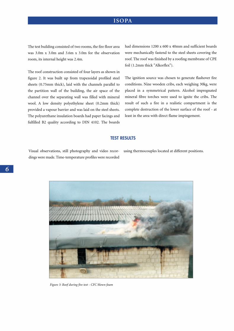
Figure 3: Roof during fire test - CFC blown foam
The test building consisted of two rooms, the fire floor area
was 3.0m x 3.0m and 3.6m x 3.0m for the observation
room, its internal height was 2.4m.
The roof construction consisted of four layers as shown in
figure 2. It was built up from trapezoidal profiled steel
sheets (0.75mm thick), laid with the channels parallel to
the partition wall of the building, the air space of the
channel over the separating wall was filled with mineral
wool. A low density polyethylene sheet (0.2mm thick)
provided a vapour barrier and was laid on the steel sheets.
The polyurethane insulation boards had paper facings and
fulfilled B2 quality according to DIN 4102. The boards
had dimensions 1200 x 600 x 40mm and sufficient boards
were mechanically fastend to the steel sheets covering the
roof. The roof was finished by a roofing membrane of CPE
foil (1.2mm thick "Alkorflex").
The ignition source was chosen to generate flashover fire
conditions. Nine wooden cribs, each weighing 30kg, were
placed in a symmetrical pattern. Alcohol impregnated
mineral fibre torches were used to ignite the cribs. The
result of such a fire in a realistic compartment is the
complete destruction of the lower surface of the roof - at
least in the area with direct flame impingement.

VISUAL OBSERVATIONS TIME (MIN)
CFC PENTANE
Flames reach interior of roof 4 5.5
Smoke emission from fire room cornice 7.5 4
Cracking of CPE foil, smoke emission 32-36 29-34
Flames on top of the roof above fire room 37.5 39
Flame spread over whole part of the roof above fire room 38-45 39-45
Flames extinguish 56 56
7
ISOPA
Figure 4: Roof during fire test - Pentane blown foam
8
ISOPA
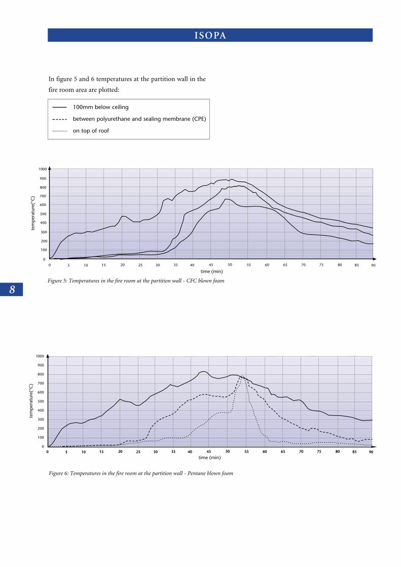
Figure 5: Temperatures in the fire room at the partition wall - CFC blown foam
tem
pera
ture
(°C
)
time (min)0 5 10 15 20 25 30 35 40 45 50 55 60 65 70 75 80 85 90
1000
900
800
700
600
500
400
300
200
100
0
Figure 6: Temperatures in the fire room at the partition wall - Pentane blown foam
0 5 10 15 20 25 30 35 40 45 50 55 60 65 70 75 80 85 900 5 10 15 20 25 30 35 40 45 50 55 60 65 70 75 80 85 900
100
200
300
400
500
600
700
800
900
1000
tem
pera
ture
(°C
)
time (min)
In figure 5 and 6 temperatures at the partition wall in the
fire room area are plotted:
100mm below ceiling
between polyurethane and sealing membrane (CPE)
on top of roof

Figure 8: Roof after test - Pentane blown foam
9
ISOPA
The results - visual observations and temperature
measurements - showed that changing the foam blowing
agent from non-flammable CFC 11 to flammable
n-pentane did not have any appreciable effect on the
fire performance of the roof construction. The roof
construction retained its integrity. Fire damage could
be confined to the part of the roof over the fire source,
there was no spread of fire across the roof to the area
over the observation room. The temperature increase in
the neighbouring room was negligible.
Figure 7: Roof after test - CFC blown foam

ISOPA
10
6.5
6.1
6.2
6.3
6.6
6.7
6.4
4.5
4.1
4.2
4.3
4.6
4.7
4.4
2.5
2.1
5.4
2.2
3.4
2.3
2.6
1.7
2.7
2.4
1.4
3.1
3.2
3.5
5.7
3.6
3.3
1.1
1.2
1.5
1.6
1.3
3.7
5.1
5.2
5.5
5.6
5.3
Figure 10: Area of roof damage, pattern, and numbers of boards, observation room left, fire room right - Pentane blown foam
6.5
6.1
6.2
6.3
6.6
6.7
6.4
4.5
4.1
4.2
4.3
4.6
4.7
4.4
2.5
2.1
5.4
2.2
3.4
2.3
2.6
1.7
2.7
2.4
1.4
3.1
3.2
3.5
5.7
3.6
3.3
1.1
1.2
1.5
1.6
1.3
3.7
5.1
5.2
5.5
5.6
5.3
Figure 9: Area of roof damage, pattern, and numbers of boards, observation room left, fire room right - CFC blown foam
Observation room
Observation room Fire room
Fire room

11
ISOPA
CONCLUSION
The results at Leipzig confirmed the TNO findings that
the contribution of the insulating material to the total
heat release was found not to be a predominant factor.
The flammability ratings of the individual insulating
materials such as polyurethane, polyisocyanurate,
expanded polystyrene, phenolic and mineral wool did not
appear to have a significant impact on the spread of fire
across the roof. In the early stages, the fire spreads due to
the fire load long before ignition or penetration of the
roofing partition occurs. The fire behaviour of roofs is
predominantly affected by the sealing layer and its quality.
The comparative tests carried out at the MFPA in Leipzig
have shown that, as far as the fire behaviour is concerned,
there is no difference between roofs insulated with
CFC-blown and pentane-blown polyurethane rigid foams.
The fire penetration time, maximum temperatures and
size of area destroyed on both types of roof are virtually
the same. The polyurethane insulation in the lightweight
steel deck roofings does not contribute to any additional
spread of flame: there was no spread of flame to the
adjacent compartment.
In addition to these full-scale tests, extensive bench
scale investigations of the burning behaviour of CFC
and pentane blown foams have shown that the same
standard classifications are achieved in both cases (7).
Summarizing all existing data, it can be concluded that
conventional types of lightweight steel deck roofing
insulated with polyurethane rigid foam do not constitute
a special fire risk provided installation work is properly
carried out. The insulation and the roofing membrane
will only be destroyed in the area immediately above
the fire room and the stability of the whole steel deck
depends mainly on the quality of the supporting
structure and the fire resistance of the neighbouring
building components.
ISOPA
12
RE F E R E N C E S
1) prEN 1187 part 1: External fire exposure to roofs,
method of test simulating exposure to burning
brands, without wind or supplementary radiant
heat.
2) prEN 1187 part 2: External fire exposure to roofs,
method of test simulating exposure to burning
brands, with wind and supplementary radiant
heat.
3) DIN 18234: Baulicher Brandschutz im
Industriebau, part I.
4) International Isocyanate Institute (III):
Model fire test on corrugated steel roof
construction reflecting real fire conditions,
Bulletin 2, 1979.
5) Zorgman, H.: Behavior of insulated steel roofs
in fully developed fires; 5th Int. Fire Protection
Seminar, Karlsruhe, 22-24 Sept. 1976, Vol.1,
p277-292.
6) Hildebrand, C.: Test report PB IV - 92 - 6:
Fire tests with PUR - insulated trapezoidal steel
roofs (in german), 1992.
7) G. Heilig, F. H. Prager, R. Walter, R. Wiedermann,
F.-W. Wittbecker: Pentan getriebene Polyurethan
(PUR) - Hartschaumstoffe - Bauphysikalische
Eigenschaften (Pentane blown polyurethane
(PUR) - rigid foams - physical properties),
Bauphysik 3/92.D
esig
n an
d pr
oduc
tion
by K
arak
as

04-97-CO
MBU
S-0030-REP
E-MAIL ADDRESSES: IEA BEISOPA1@IBMMAIL X400 c=BE; a=IBMX400; p=IBMMAIL; s=STROBBE; g=GEERT INTERNET [email protected]
Avenue E. Van Nieuwenhuyse Laan 41160 Brussels BelgiumTel 32 2 676 74 75Fax 32 2 676 74 79
European Isocyanate
Producers Association