fire alarm system - awexawex.eu/fs/wp-content/uploads/sites/3/online_fas_17_1.pdf · contents...
TRANSCRIPT

Fire Alarm SystemVER.17.1

AWEX BRAND
The AWEX brand has existed since 2002, and has been carrying out clearly defined mission: modern products with the highest quality and the satisfaction of customers. We offer the full range of products concerning emergency lighting which meet European standards. Within 15 years of our presence on the market, due to involvement of our knowledge, funds, co-operation with the best specialists, including research facilities, and investments in innovative undertakings we achieved the position of the leader in the industry. AWEX company means the most modern technologies, expert team of designers and engineers, the highest quality, reliability of devices, diversified offer, unique design, unlimited production capacity and flawless reputation confirmed by references. Satisfaction and trust of our customers is our greatest prize. We also enjoy the consideration of independent experts. We were awarded with the title:“Export Leader 2006” [„Lider Eksportu 2006”] for a saleslevel achieved, and the Puls Biznesu awarded us twicewith the „Gazele Biznesu” distinction as one of the mostdynamically developing companies.
PROFESSIONAL PERSONNEL
We employ the best specialists in many fields whom we guarantee constant improvement of their qualifications through specialised trainings. Our design department provides flexibility adjusted to individual needs, and the team of highly qualified engineers guarantees constant technical progress of devices offered by us. Application of the modern methods of the flow of information in the company allows us to keep our offer, as well as functionality of the products up-to-date. Effective projects management allows us to establish solid relationships with our counterparties, based on trust.
INVESTMENTS
We apply the latest world technologies which guarantee quality, precision in production, the optimisation of technological process and work ergonomics. We invest our time and funds to make each stage of manufacture of our products contributing to meet all expectations on the part of our clients.
RESEARCH
Research and development conducted by us guarantee constant update of our offer oriented towards the development of the industry, due to which we provide the most modern, multifunctional and technologically advanced products.
WE CARE ABOUT ENVIRONMENT
We offer products which are friendly for the natural environment, and the technological process meets high standards of the EU.
GUARANTEE OF QUALITY
With a view to doing the mission of our company, we have implemented the Quality Management System according to the EN ISO 9001:2008 standard, and the certificate issued to us by TÜV NORD guarantees the highest quality of design, manufacture, assemble and service of manufactured devices.

CONTENTS
CONTROL UNITS 4
FIRE ALARM CONTROL UNIT FAS 5
CONTROL UNIT EXTENTION CARDS 7
EXTERNAL SIgNAL pANEL ESp 8 CENTRAL NETWORK 9
FIRE DETECTORS 10
SMOKE DETECTOR S 11
HEAT DETECTOR T 12
HEAT AND SMOKE DETECTOR TS 13
SMOKE DETECTOR WITH THE vISUAL SIgNALLINg DEvICE SF 14
HEAT DETECTOR WITH THE vISUAL SIgNALLIg DEvICE TF 15
HEAT AND SMOKE DETECTOR WITH THE vISUAL SIgNALLINg DEvICE TSF 16
MANUAL CALL POINTS 18
MANUAL CALL pOINT ROp 21 18
MANUAL CALL pOINT ROp 65 19
INPUT/OUTPUT MODULES 20
INpUT/OUTpUT MODULE MIO 22 20
INpUT/OUTpUT MODULE MIO 44 20
INpUT/OUTpUT MODULE MIO 88 20
INDICATORS 21
STATUS INDICATOR WZ 4 21
ACCESSORIES 22
Fire Alarm System
4
Control units
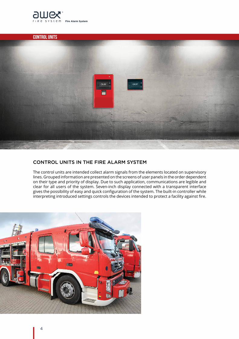
CONTROL UNITS IN THE FIRE ALARM SYSTEM
The control units are intended collect alarm signals from the elements located on supervisory lines. Grouped information are presented on the screens of user panels in the order dependent on their type and priority of display. Due to such application, communications are legible and clear for all users of the system. Seven-inch display connected with a transparent interface gives the possibility of easy and quick configuration of the system. The built-in controller while interpreting introduced settings controls the devices intended to protect a facility against fire.

Fire Alarm System
5
Control units
FIRE ALARM CONTROL UNIT FAS
The control unit is manufactured in the module technique which makes it easy to expand and service. In the basic it has a user’s panel, a control module with a supervisory loop, a power supply unit and a set of batteries. You can expand and adjust the control unit to your own need through installations and programming appropriate expansion cards.
Optionally, the control units may be monitored through the TCP/IP protocol. Remote access to the system service is available through dedicated software or on the website.
Application of the RJ-45 connector and the IP technology allows to integrate the system and the building management systems (BMS), with the Safety management systems (SMS) and the visualisation systems (SMART VISIO).
ROUTER
BMS BUILDING MANAGEMENT SYSTEM
NETWORK PC
Characteristics of the control unit FAS
•Up to 7 supervisory loops•Up to 250 elements per a loop•Up to 250 supervisory zones per a loop•Outputs built-in•UTA•Signal lines•Fault•Universal relay
•Maximum loop length 2000m•Loop interval detection•Events counter up to 15,000•Expansion cards•Conformity with EN 54-2, EN 54-4
standard•7-Inch touch screen•Printer built-in•Modbus, BACnet interface
Fire Alarm System
6
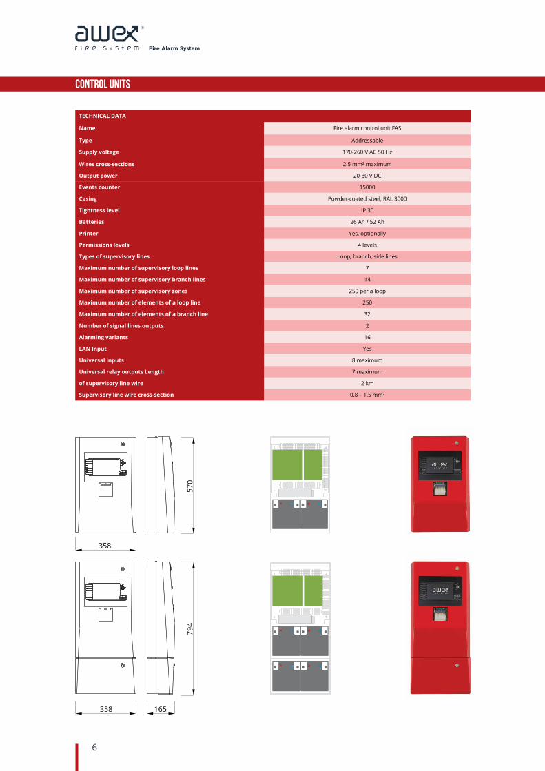
TECHNICAL DATA
Name Fire alarm control unit FAS
Type Addressable
Supply voltage 170-260 V AC 50 Hz
Wires cross-sections 2.5 mm² maximum
Output power 20-30 V DC
Events counter 15000
Casing Powder-coated steel, RAL 3000
Tightness level IP 30
Batteries 26 Ah / 52 Ah
Printer Yes, optionally
Permissions levels 4 levels
Types of supervisory lines Loop, branch, side lines
Maximum number of supervisory loop lines 7
Maximum number of supervisory branch lines 14
Maximum number of supervisory zones 250 per a loop
Maximum number of elements of a loop line 250
Maximum number of elements of a branch line 32
Number of signal lines outputs 2
Alarming variants 16
LAN Input Yes
Universal inputs 8 maximum
Universal relay outputs Length 7 maximum
of supervisory line wire 2 km
Supervisory line wire cross-section 0.8 – 1.5 mm²
Control units
358
794
570
358 165

Fire Alarm System
7
Control units
CONTROL UNIT EXTENTION CARDS
TECHNICAL DATA
Name Supervisory loops card KPD 2
Installation inside the FAS control unit
Number of supervisory loops 2
Line structure loop, branch
Maximum number of elements up to 250 per a loop
Maximum length of a wire 2000m
Maximum number of cards 3
Product code FSC0000001
TECHNICAL DATA
Name Input/Outputs card KIO 22
Installation inside the FAS control unit
Monitoring input signal monitoring
Number of inputs 2 supervised inputs
Number of outputs 2 relay outputs
Maximum input load 30V DC 0.5A
Maximum number of cards 3
Product code FSC0000002
TECHNICAL DATA
Installation Communication card KRS 422
Maximum number of central units inside the FAS control unit 10
Maximum number of remotecontrol panels 10
Maximum length of a wire 1000m
Maximum number of cards 1
Connection type doubled loop
Product code FSC0000003
Fire Alarm System
8
Control units
EXTERNAL SIGNAL PANEL ESP
The ESP panel allows to control the fire alarm control unit from a place which is distant from a physical localisation of the control unit by reproducing its interface by displaying, among others: alarm, fault, block and test communicates.
Due to application of the remote control panel, the fire alarm control unit may be installed in the most comfortable place from the point of view of the topology of the system, whilst the panel may be placed near the personnel handling the fire alarm system.
It is possible to verify alarming of the control unit, and then, remove the signalling. The panel controls its own systems and signals their possible fault. Efficiency of the signalling elements of the terminal can be tested. Accessibility to the manipulative elements and determined functions was diversified and divided into the access levels.
263
4918
4
CharacteristicsoftheESPremote panel
•Double interface of the control unit•7-Inch touch screen•4 levels of access•Multi-language service•Access blockade by using a key•Compact casing
Dimensions (mm):
TECHNICAL DATA
Name External signal panel ESP
Device type The device for remote signalling and servicing
Protection degree IP 30
Range of operating temperatures -5° C to +40° C
Dimensions 263x184x49mm
Supply voltage 24V DC
Maximum current consumption 150mA
Weight 2000g
Maximum number of devices 10 per a network
Product code FSP0000001
Fire Alarm System
9
Control units
CENTRAL NETWORK
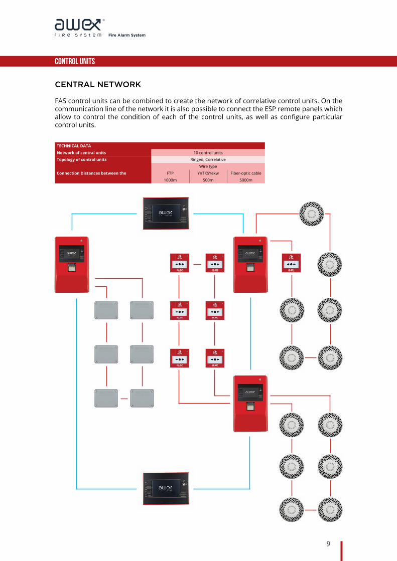
FAS control units can be combined to create the network of correlative control units. On the communication line of the network it is also possible to connect the ESP remote panels which allow to control the condition of each of the control units, as well as configure particular control units.
TECHNICAL DATA
Network of central units 10 control units
Topology of control units Ringed, Correlative
Connection Distances between the
Wire type
FTP YnTKSYekw Fiber-optic cable
1000m 500m 5000m

Fire Alarm System
10
Fire detectors
Fire detectors of the AWEX fire alarm systems are intended for detecting fires in their early phase. The detectors, because of their types can have the following sensors: heat, smoke, or combined sensors of smoke and heat, and an additional visual indicator. Detection systems applied in the detectors guarantee certainty and reliability in detecting fire. The heat detection is realised by means of 4-thermistor ambient temperature measurement system, on the other hand, the smoke detection system is being realised by means of photodiodes which uses the phenomenon of light dispersion. In case of detectors equipped with both fire detection systems it is possible, depending on a need an the place of installation, turn off one of the sensors using the control unit by selecting appropriate detector operation mode.
Every element is equipped with double-sided short-circuit isolator which ensures continuous operation of the loop, despite a short-circuit on the line and enables an easy localisation of a fault. Additionally, the detectors are monitoring their state of soiling continuously by sending the information on a possible need of their cleaning to the control unit. State of soiling is taken into consideration in the detection algorithm, thereby increasing the certainty of the fire detection.

Fire Alarm System
11
Fire detectors
SMOKE DETECTOR S
The smoke detector is intended for detecting fire in its early phase. The detector has an optic, scattering smoke sensor. The application of such type of a sensor allows to detect fire quick and with certainty.
The detector operates within the AWEX fire alarm system. The element can be installed on the loop addressable supervisory lines and on the side addressable line.
The smoke detection takes place in a detection chamber equipped with photoelectric diodes. Smoke goes to the chamber during fire. The particles of smoke reflect the light emitted by light emitting diodes which causes that an IR diode receives the signal and transmits it to a microprocessor. Then, it recognises the type of alarm and transmits it to the supervisory line, and to the control unit.
Characteristics of the smoke detector:
•The level of sensitivity comply with the EN 54 standard•Recognition of the state of soiling•Regulation of alarm threshold which compensates theinfluenceoftheenvironment•Indication of an alarm by means of the LED diode•Additional LED diodes for the testing state•External status indicator•The possibility of disconnection of particular
detectors•Integrated short-circuit isolator•Acasingwithalowprofile•Operation in the addressable systems
S detector operation mode
Dimensions (mm):
TECHNICAL DATA
Name Smoke detector S
Smoke detection optical, scattering
Supply voltage 24V DC
Current during supervision <160 μA
Current during alarming <550 μA
Working temperature from -25°C to 55°C
Tightness protection level IP 20
Acceptable relative humidity 95% at the temp. of 35°C without
Visual signalling condensation LED diode, red, green
Dimensions Ø110 x 51 mm
Weight 200 g
Detector colour White
Usefulness for test fires detecting According to 54-7
Product code FSD0000002110
110
51
Fire Alarm System
12
Fire detectors
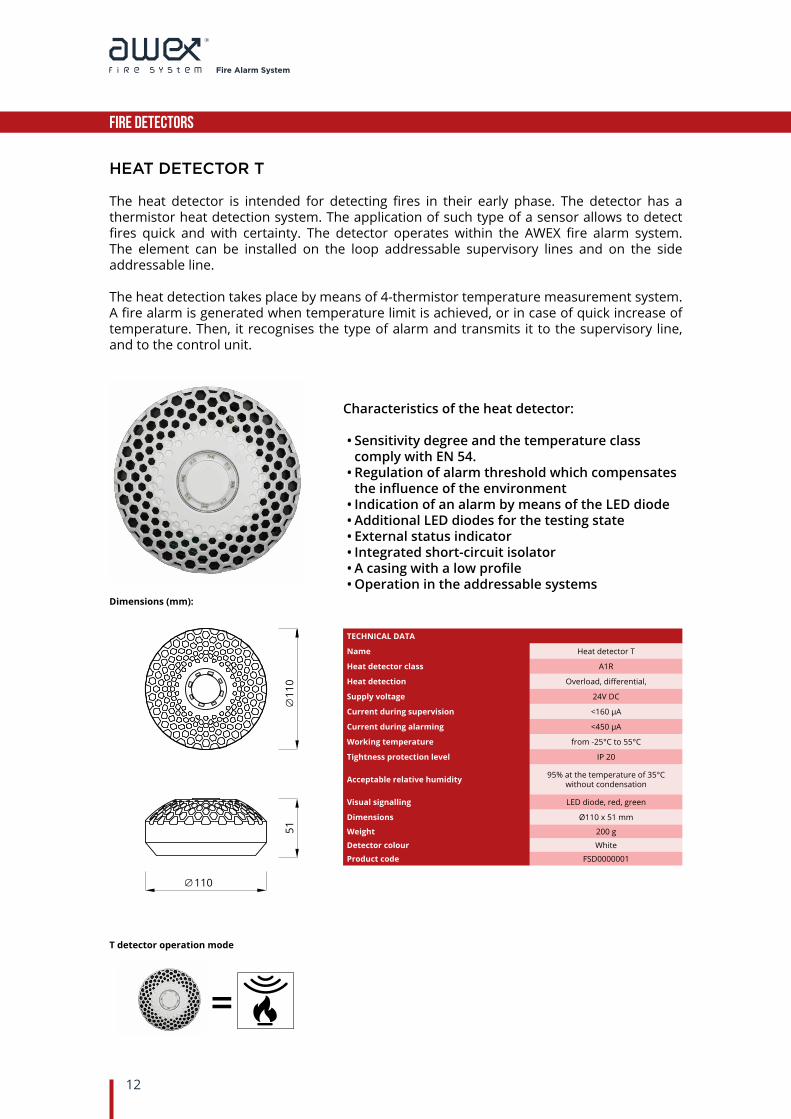
HEAT DETECTOR T
The heat detector is intended for detecting fires in their early phase. The detector has a thermistor heat detection system. The application of such type of a sensor allows to detect fires quick and with certainty. The detector operates within the AWEX fire alarm system. The element can be installed on the loop addressable supervisory lines and on the side addressable line.
The heat detection takes place by means of 4-thermistor temperature measurement system. A fire alarm is generated when temperature limit is achieved, or in case of quick increase of temperature. Then, it recognises the type of alarm and transmits it to the supervisory line, and to the control unit.
Characteristics of the heat detector:
•Sensitivity degree and the temperature class comply with EN 54.•Regulation of alarm threshold which compensates theinfluenceoftheenvironment•Indication of an alarm by means of the LED diode•Additional LED diodes for the testing state•External status indicator•Integrated short-circuit isolator•Acasingwithalowprofile•Operation in the addressable systems
T detector operation mode
Dimensions (mm):
TECHNICAL DATA
Name Heat detector T
Heat detector class A1R
Heat detection Overload, differential,
Supply voltage 24V DC
Current during supervision <160 μA
Current during alarming <450 μA
Working temperature from -25°C to 55°C
Tightness protection level IP 20
Acceptable relative humidity 95% at the temperature of 35°C without condensation
Visual signalling LED diode, red, green
Dimensions Ø110 x 51 mm
Weight 200 g
Detector colour White
Product code FSD0000001
110
110
51

Fire Alarm System
13
Fire detectors
HEAT AND SMOKE DETECTOR TS
The heat and smoke detector is intended for detecting fires in their early phase. The detector has two sensors: heat and smoke. The application of two types of a sensor allows to detect all types of fires quickly and with certainty. The detector operates within the AWEX fire alarm system. The element can be installed on the loop addressable supervisory lines and on the side addressable line.
The smoke and heat detector with two sensors is equipped with two sensors which detect fire. The smoke detection takes place in a detection chamber equipped with photoelectric diodes. Smoke goes to the chamber during fire. The particles of smoke reflect the light emitted by light emitting diodes which causes that an IR diode receives the signal and transmits it to a microprocessor. The heat detection takes place by means of 4-thermistor temperature measurement system. A fire alarm is generated when temperature limit is achieved, or in case of quick increase of temperature. Then, it recognises the type of alarm and transmits it to the supervisory line, and to the control unit.
Characteristics of the heat and smoke detector:
•Sensitivity degree and the temperature class comply with EN 54.•Recognition of the state of soiling•Regulation of alarm threshold which compensates theinfluenceoftheenvironment•Smoke analysis supported by the heat analysis
function•The possibility of disconnection of particular detectors•Indication of an alarm by means of the LED diode•Additional LED diodes for the testing state•External status indicator•Integrated short-circuit isolator•Acasingwithalowprofile•Operation in the addressable systems
TS detector operation mode
Dimensions (mm):
TECHNICAL DATA
Name Heat and smoke detector TS
Heat detector class A1R
Smoke detection Optical, scattering,
Heat detector detection Overload, differential,
Working voltage 24V DC
Current during supervision <160 μA
Current during alarming <550 μA
Working temperature from -25°C to 55°C
Tightness protection level IP 20
Acceptable relative humidity 95% at the temperature of 35°C without condensation
Visual signalling LED diode, red, green
Dimensions Ø110 x 51 mm
Weight 200 g
Detector colour White
Usefulness for test fires detecting According to 54-7
Product code FSD0000003
110
110
51

Fire Alarm System
14
Fire detectors
SMOKE DETECTOR WITH THE VISUAL SIGNALLING DEVICE SF
The smoke detector is intended for detecting fire in its early phase. The detector has an optic, scattering smoke sensor. The application of such type of a sensor allows to detect fire quick and with certainty.
Additionally, the detector has the flashing visual signalling device built-in due to which the detector fire alarm is visible from a large distance. The detector operates within the AWEX fire alarm system. The element can be installed on the loop addressable supervisory lines and on the side addressable line.
The smoke detection takes place in a detection chamber equipped with photoelectric diodes. Smoke goes to the chamber during fire. The particles of smoke reflect the light emitted by light emitting diodes which causes that an IR diode receives the signal and transmits it to a microprocessor. Then, it recognises the type of alarm and transmits it to the supervisory line, and to the control unit.
Characteristics of the smoke detector:
•The level of sensitivity comply with the EN 54 standard•Recognition of the state of soiling•Regulation of alarm threshold which compensates theinfluenceoftheenvironment•Indication of an alarm by means of the LED diode•Additional LED diodes for the testing state•External status indicator•Integrated short-circuit isolator•Acasingwithalowprofile•Operation in the addressable systems
SF detector operation mode
Dimensions (mm):
TECHNICAL DATA
Name Smoke detector with the visual signalling device SF
Smoke detection Optical, scattering
Supply voltage 24V DC
Current during supervision <160 μA
Current during alarming <2 mA
Working temperature from -25°C to 55°C
Tightness protection level IP 20
Acceptable relative humidity 95% at the temperature of 35°C without condensation
Visual signalling Green LED diode, red FLASH LED diode
Dimensions Ø110 x 51 mm
Weight 200 g
Detector colour white
Usefulness for test fires detecting According to 54-7
Product code FSD0000005110
110
51

Fire Alarm System
15
Fire detectors
HEAT DETECTOR WITH THE VISUAL SIGNALLIG DEVICE TF
The heat detector is intended for detecting fires in their early phase. The detector has a thermistor heat detection system. The application of such type of a sensor allows to detect fires quick and with certainty.
The detector operates within the AWEX fire alarm system. The element can be installed on the loop addressable supervisory lines and on the side addressable line. Additionally, the detector has the flashing visual signalling device built-in due to which the detector fire alarm is visible from a large distance.
The heat detection takes place by means of 4-thermistor temperature measurement system. A fire alarm is generated when temperature limit is achieved, or in case of quick increase of temperature. Then, it recognises the type of alarm and transmits it to the supervisory line, and to the control unit.
Characteristics of the heat detector:
•Sensitivity degree and the temperature class comply with EN 54.•Regulation of alarm threshold which compensates theinfluenceoftheenvironment•Indication of an alarm by means of the LED diode•Additional LED diodes for the testing state•External status indicator•Integrated short-circuit isolator•Acasingwithalowprofile•Operation in the addressable systems
TF detector operation mode
Dimensions (mm):
TECHNICAL DATA
Name Heat detector with the visual signalling device TF
Heat detector class A1R
Heat detection Overload, differential
Supply voltage 24V DC
Current during supervision <160 μA
Current during alarming <2 mA
Working temperature from -25°C to 55°C
Tightness protection level IP 20
Acceptable relative humidity 95% at 35°C without condensation
Visual signalling Green LED diode, red FLASH LED diode
Dimensions Ø110 x 51 mm
Weight 200 g
Detector colour White
Product code FSD0000004
110
110
51

Fire Alarm System
16
Fire detectors
HEAT AND SMOKE DETECTOR WITH THE VISUAL SIGNALLING DEVICE TSF
The heat and smoke detector is intended for detecting fires in their early phase. The detector has two sensors: heat and smoke. The application of two types of a sensor allows to detect all types of fires quickly and with certainty. The two-sensor detector operates within the AWEX fire alarm system. The element can be installed on the loop addressable supervisory lines and on the side addressable line. Additionally, the detector has the flashing visual signalling device built-in due to which the detector fire alarm is visible from a large distance.
The two-sensor smoke and heat detector is equipped with two sensors for fire detection. The smoke detection takes place in a detection chamber equipped with photoelectric diodes. Smoke goes to the chamber during fire. The particles of smoke reflect the light emitted by light emitting diodes which causes that an IR diode receives the signal and transmits it to a microprocessor.
The heat detection takes place by means of 4-thermistor temperature measurement system. A fire alarm is generated when temperature limit is achieved, or in case of quick increase of temperature. Then, it recognises the type of alarm and transmits it to the supervisory line, and to the control unit.przekazuje go do mikroprocesora.
Characteristics of the heat and smoke detector:
•Sensitivity degree and the temperature class comply with EN 54.•Recognition of the state of soiling•Regulation of alarm threshold which compensates theinfluenceoftheenvironment•Indication of an alarm by means of the LED diode•Additional LED diodes for the testing state•External status indicator•Integrated short-circuit isolator•Acasingwithalowprofile•Operation in the addressable systems
TSF detector operation mode
Dimensions (mm):
TECHNICAL DATA
Name Heat and smoke detector with the visual signalling device TSF
Heat detector class A1R
Smoke detection Optical, scattering,
Heat detection Overload, differential,
Supply voltage 24V DC
Current during supervision <160 μA
Current during alarming <2 mA
Working temperature from -25°C to 55°C
Tightness protection level IP 20
Acceptable relative humidity 95% at the temp. of 35°C without condensation
Visual signalling green LED diode, red FLASH LED diode
Dimensions Ø110 x 51 mm
Weight 200 g
Detector colour White
Product code FSD0000004
Usefulness for test fires detecting According to 54-7
110
110
51
Fire Alarm System
17
Fire detectors
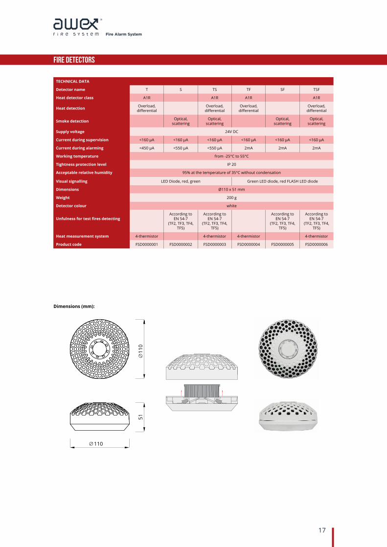
Dimensions (mm):
TECHNICAL DATA
Detector name T S TS TF SF TSF
Heat detector class A1R A1R A1R A1R
Heat detection Overload,differential
Overload,differential
Overload,differential
Overload,differential
Smoke detection Optical,scattering
Optical,scattering
Optical,scattering
Optical,scattering
Supply voltage 24V DC
Current during supervision <160 μA <160 μA <160 μA <160 μA <160 μA <160 μA
Current during alarming <450 μA <550 μA <550 μA 2mA 2mA 2mA
Working temperature from -25°C to 55°C
Tightness protection level IP 20
Acceptable relative humidity 95% at the temperature of 35°C without condensation
Visual signalling LED Diode, red, green Green LED diode, red FLASH LED diode
Dimensions Ø110 x 51 mm
Weight 200 g
Detector colour white
Unfulness for test fires detectingAccording to
EN 54-7(TF2, TF3, TF4,
TF5)
According toEN 54-7
(TF2, TF3, TF4, TF5)
According toEN 54-7
(TF2, TF3, TF4, TF5)
According toEN 54-7
(TF2, TF3, TF4, TF5)
Heat measurement system 4-thermistor 4-thermistor 4-thermistor 4-thermistor
Product code FSD0000001 FSD0000002 FSD0000003 FSD0000004 FSD0000005 FSD0000006
110
110
51
Fire Alarm System
18
MANUAL CALL POINTS
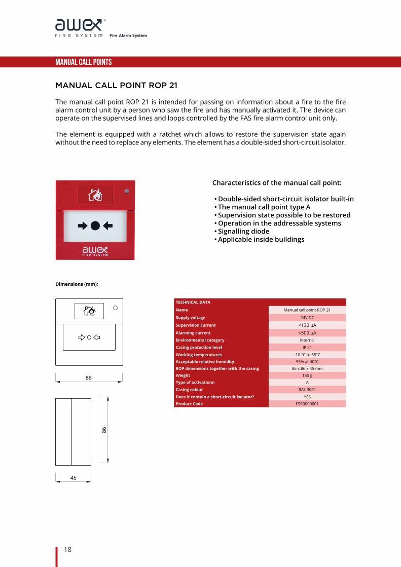
MANUAL CALL POINT ROP 21
The manual call point ROP 21 is intended for passing on information about a fire to the fire alarm control unit by a person who saw the fire and has manually activated it. The device can operate on the supervised lines and loops controlled by the FAS fire alarm control unit only.
The element is equipped with a ratchet which allows to restore the supervision state again without the need to replace any elements. The element has a double-sided short-circuit isolator.
Characteristics of the manual call point:
•Double-sided short-circuit isolator built-in•The manual call point type A•Supervision state possible to be restored•Operation in the addressable systems•Signalling diode•Applicable inside buildings
Dimensions (mm):
TECHNICAL DATA
Name Manual call point ROP 21
Supply voltage 24V DC
Supervision current <130 μAAlarming current <500 μAEnvironmental category Internal
Casing protection level IP 21
Working temperatures -10 °C to 55°C
Acceptable relative humidity 95% at 40°C
ROP dimensions together with the casing 86 x 86 x 45 mm
Weight 150 g
Type of activationn A
Casing colour RAL 3001
Does it contain a short-circuit isolator? YES
Product Code FSR0000001
86
45
86

Fire Alarm System
19
MANUAL CALL POINTS
MANUAL CALL POINT ROP 65
The manual call point ROP 65 is intended for passing on information about a fire to the fire alarm control unit by a person who saw the fire and has manually activated it. The device can operate on the supervised lines and loops controlled by the FAS fire alarm control unit only.
The element is activated by breaking a glass. When the call point is activated, it is necessary to replace the glass for a new one. The element has a double-sided short-circuit isolator.
Dimensions (mm):
TECHNICAL DATA
Name Manual call point ROP 65
Supply voltage 24V DC
Supervision current <130 μAAlarming current <500 μAEnvironmental category Internal/External
Casing protection level IP 65
Working temperatures -25°C to 70°C
Acceptable relative humidity 95% at 40°C
ROP dimensions together with the casing 115 x 115 x 60 mm
Weight 300 g
Type of starting A
Casing colour RAL 3001
Does it contain a short-circuit isolator? YES
Product code FSR0000002
Characteristics of the manual call point:
•Double-sided short-circuit isolator built-in•The A type call point•Supervision state possible to be restored
through replacement of the glass•Operation in the addressable systems•Signalling diode•Application inside and outside buildings
60
115
115

Fire Alarm System
20
INPUT/OUTPUT MODULES
INPUT/OUTPUT MODULE MIO 22, MIO 44, MIO 88
The MIO module is the input/output device intended for the co-operation between fire-fighting devices and the AWEX fire alarm system. It is intended for the operation on the supervision, addressable, loop, and side lines. The device can cooperate with acoustic signalling devices, emergency exit doors, smoke venting systems, CO2 automatic extinguishing systems, and other devices intended for the fire protection. The MIO modules are equipped with 2, 4, or 8 relay outputs, and 2, 4, or 8 inputs without supervised potentials, depending on their version. The element has integrated short-circuit isolator which allows quickly location of fault and appropriate operation of the loop line, even in the event of its fault.
150
77
190
6711
6
150
57
114
114
TECHNICAL DATA
Input/output module name MIO 22 MIO 44 MIO 88
Casing type T N T N T N
Supply voltage 24V DC
Short-circuit isolator Built-in, double-sided
Outputs number 2 4 8
Relaying control outputsRelay output (NO/NC/COM).
AC contact load capacity: 2A 250 V 60 WDC contact load capacity: 2A 220 V 60 W
Inputs number 2 4 8
Input function Active, Inactive, Short-Circuit, Interval
Input control Yes
Input initiation Parametrising through resistance (22 kΩ)
Casing tightness IP 66 IP 67 IP 66 IP 67 IP 66 IP 67
Dimensions 114 x 114 x 57 mm 118 x 118 x 67 mm 150 x 116 x 67 mm 187 x 118 x 67 mm 190 x 150 x 77 mm 187 x 118 x 67 mm
Weight 200 g 280 g 480 g
Working temperature Od -25°C do 70°C Od -25°C do 70°C Od -25°C do 70°C
Product code FSM0000001 FSM0000004 FSM0000002 FSM0000005 FSM0000003 FSM0000006

Fire Alarm System
21
SIGNALLING DEVICES
STATUS INDICATOR WZ 4
The WZ 4 status indicator is intended for optical repetition of the signalling alarming state of the detector or a group of detectors in the fire alarm systems. It can be added to the detector or a group of detectors. The indicator is applied when installed detector is invisible or there is limited access to a room supervised by detectors, for example, it is installed in spaces above ceiling, in cable passages, technical rooms, hotel rooms, etc.
Characteristics:
•Additional visual signalling•Small dimensions•4 LED signalling diodes•Consumption of current <4mA
TECHNICAL DATA
Name Status indicator WZ 4
Supply voltage 16 – 30 VDC
Consumption of current during 0 mA
Consumption of current during alarming <4 mA
Dimensions Ø44 x 23 mmWeight 18 gProduct code FSS0000001
Dimensions (mm):
44
23

Fire Alarm System
22
Accessories
NAME PHOTO TECHNICAL DRAWING PRODUC CODE
DETECTOR BASE FSD0000007
DUST COVER FSD0000008
MIO TESTINGMODULE FSM0000004
PANE GLASS FOR ROP 65 FSR0000003
KEY FOR ROP 21 FSR0000004
SIGNALLING DEVICESA-K5N FSS0000002
SIGNALLING DEVICESA-K7N FSS0000003
124
41 66
70
2 70
38
174,8
119,
5
30
110
18
62
115
100
115

Fire Alarm System
NOTes
We inform that AWEX company cares about its constant development and improvement of its products, according to the latest technological trends. We reserve the right to introduce changes in the design and technical data of our products without prior notice. Data included in this publication are intended for informational purposes only, and cannot be the ground of legal claims.

DystrybutorAWEX SP. Z O. O. SPÓŁKA KOMANDYTOWAMasłomiąca, ul. Długa 3932-091 Michałowice, Poland tel.: (+48) 12 681 55 00, fax: (+48) 12 681 55 26e-mail: [email protected]