finnish experiences on grid effects of...
TRANSCRIPT
1 Jarmo Elovaara Oct. 25, 2005© Fingrid Oyj
FINNISH EXPERIENCES ON GRID EFFECTS OF GIC'S
ESA-SPACE WEATHER WORKSHOPThe Netherlands
17. November, 2005by
J. Elovaara
2 Jarmo Elovaara Oct. 25, 2005© Fingrid Oyj
FINNISH EXPERIENCES ON GRID EFFECTS OF GIC'S
Content:
1. About the potential effects of GIC's in electric grids
2. About the Finnish measurement campaigns3. Research co-operation with FMI4 Grid experiences in Finland and in Nordic
countries5. Reasons to good Finnish experiences
3 Jarmo Elovaara Oct. 25, 2005© Fingrid Oyj
FINNISH EXPERIENCES ON GRID EFFECTS OF GIC'SPotential effects of GIC's in the electrical networks:
DC-half-cycle magnetization of transformers which causes saturation of the transformers and increase of the leakage fluxes in the transformerConsequences of transformer saturation
– increase of the reactive power demand in the system -risk of reactive power unbalance and voltage instability
– generation of harmonic voltages and currents - protection relays may operate incorrectly => erroneous/unnecessa-ry trippings leading to black-outs
– impaired quality of supply voltage (non-sinusoidal form)Increased leakage fluxes might cause
– hot spots in the metallic parts of the transformer– these might deteriorate the organic insulation materials
4 Jarmo Elovaara Oct. 25, 2005© Fingrid Oyj
FINNISH EXPERIENCES ON GRID EFFECTS OF GIC'S
Large GI-currents in transmission systems can occur, when:
the overhead lines are long (high longitudinal E on the surface of the earth along the line)the specific resistivity of the ground is high (in Finland the median value of the resistivity of the surface layers is 2300 Ωm because the solid rock is near the surface of the earth)the grid has an electrical connection to the earththe country is situated at the high latitudes (auroral zone)
5 Jarmo Elovaara Oct. 25, 2005© Fingrid Oyj
FINNISH EXPERIENCES ON GRID EFFECTS OF GIC'S
About the GIC-measurements in the Finnish 400 kV grid
The Finnish 400 kV (and 220 kV) grid(s) are effectively earthed, i.e. the neutral points of the 400 kV windings of the system transformers (400/400/125 MVA, 417/117/21 kV) are earthed (via fault-current limiting reactors) in most substationsConsequently, geomagnetically induced currents can occur in the 400 kV overhead line network and they flow especially between transformers which have grounded neutral pointsThe occurrence of the GIC's has been monitored since 1976 by measuring pseudo-stationary DC-currents from the 400 kV neutrals of certain system transformers
6 Fingrid Oyj Oct. 25, 2005© Fingrid Oyj
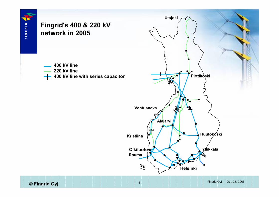
400 kV line220 kV line400 kV line with series capacitor
(220)
(220)
Olkiluoto
Helsinki
Rauma
Pirttikoski
Huutokoski
Yllikkälä
Utsjoki
Kristiina
Ventusneva
Fingrid's 400 & 220 kVnetwork in 2005
Alajärvi

7 Jarmo Elovaara Oct. 25, 2005© Fingrid Oyj
FINNISH EXPERIENCES ON GRID EFFECTS OF GIC'SExample about the use of a current limiting reactor(the ohm-values indicate the inductive reactance)
8 Jarmo Elovaara Oct. 25, 2005© Fingrid Oyj
FINNISH EXPERIENCES ON GRID EFFECTS OF GIC'S
The GIC´s through transformers are measured(continuously) with a help of a resistor in the neutral point (now also other technologies can be used)Measurement points have been selected on the basis of probabilities how GIC's occur in the Finnish system and the measurement points have changed during the years
– examples of measurement places are Huutokoski, Rauma, Yllikkälä, Pirttikoski, perhaps in future also Alajärvi and Kristiina/Ventusneva (criteria e.g. the latitude of the substation, is the substation a corner point in the system, better coverage in 220 kV grid...)
– once even the GIC of a line (Nurmijärvi-Loviisa) was measured with a help of a magnetometer
9 Jarmo Elovaara Oct. 25, 2005© Fingrid Oyj
FINNISH EXPERIENCES ON GRID EFFECTS OF GIC'S
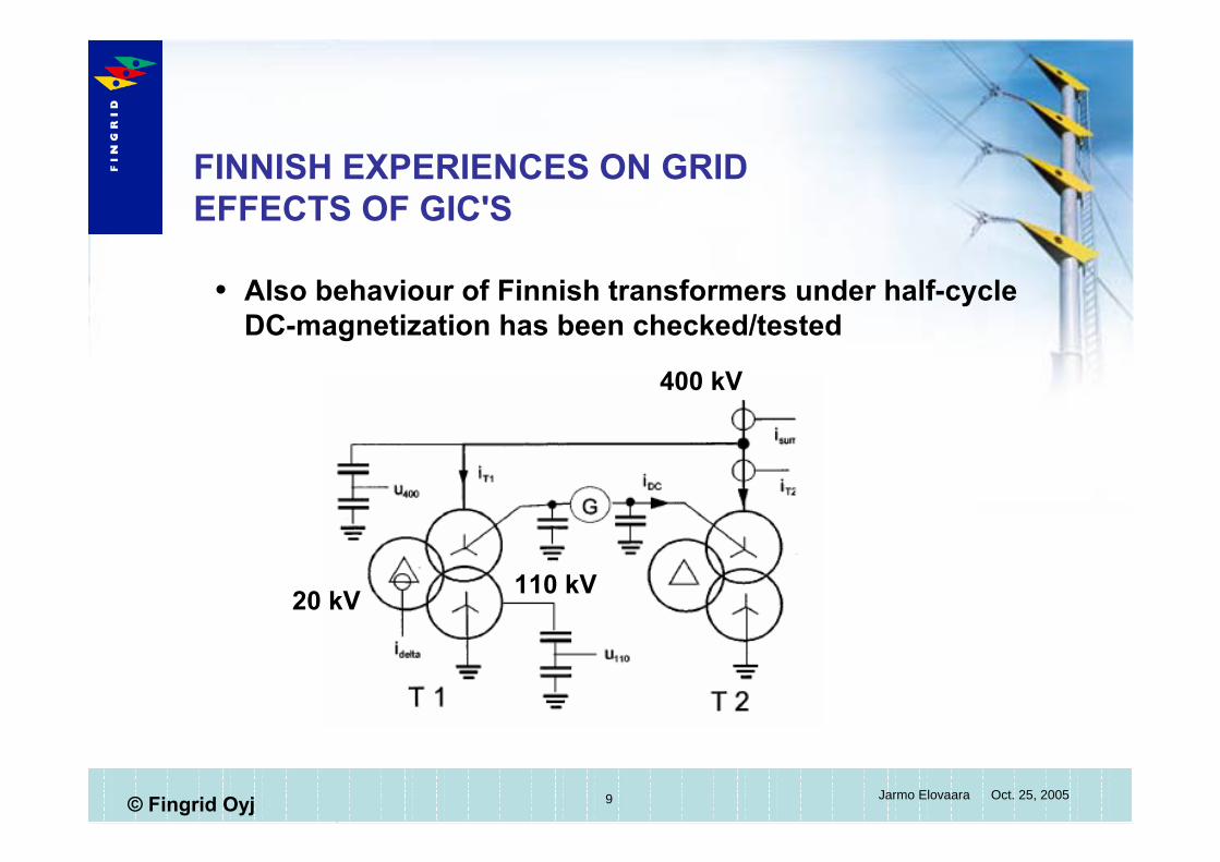
Also behaviour of Finnish transformers under half-cycle DC-magnetization has been checked/tested
400 kV
110 kV20 kV
10 Jarmo Elovaara Oct. 25, 2005© Fingrid Oyj
FINNISH EXPERIENCES ON GRID EFFECTS OF GIC'S
The largest GIC's measured so far are:Huutokoski 165 A/10 s -value (Jan 4, 1979)Rauma 200 A/1 min and Pirttikoski 53 A/1 min (March 24, 1991)Rauma 190 A/1 min and Pirttikoski 38 A/1 min (March 25, 1991)
Since then essential changes in the grid has been made (e.g. series capacitors taken into operation) and at present the neutral currents are smaller
Examples of the time trends of the currents in transformer neutrals are given in the following
11 Jarmo Elovaara Oct. 25, 2005© Fingrid Oyj
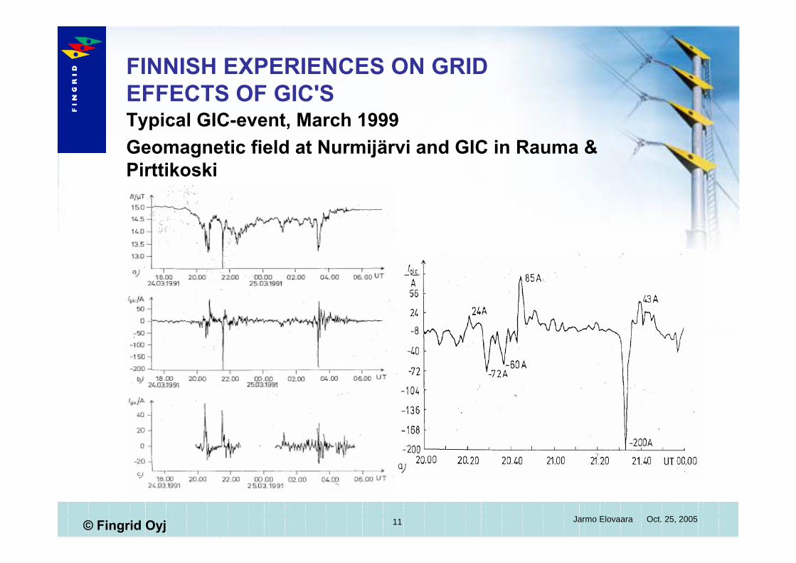
FINNISH EXPERIENCES ON GRID EFFECTS OF GIC'STypical GIC-event, March 1999Geomagnetic field at Nurmijärvi and GIC in Rauma & Pirttikoski
12 Jarmo Elovaara Oct. 25, 2005© Fingrid Oyj
FINNISH EXPERIENCES ON GRID EFFECTS OF GIC'S
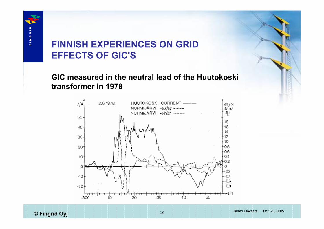
GIC measured in the neutral lead of the Huutokoski transformer in 1978
13 Jarmo Elovaara Oct. 25, 2005© Fingrid Oyj
FINNISH EXPERIENCES ON GRID EFFECTS OF GIC'S
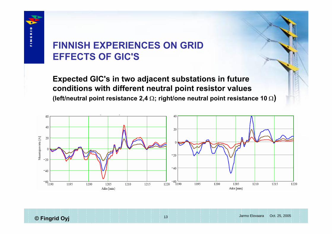
Expected GIC's in two adjacent substations in future conditions with different neutral point resistor values (left/neutral point resistance 2,4 Ω; right/one neutral point resistance 10 Ω)
14 Jarmo Elovaara Oct. 25, 2005© Fingrid Oyj
FINNISH EXPERIENCES ON GRID EFFECTS OF GIC'S
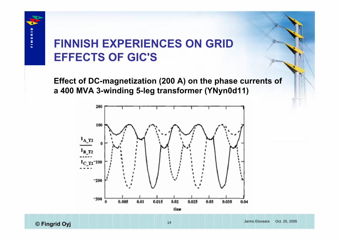
Effect of DC-magnetization (200 A) on the phase currents of a 400 MVA 3-winding 5-leg transformer (YNyn0d11)
15 Jarmo Elovaara Oct. 25, 2005© Fingrid Oyj
FINNISH EXPERIENCES ON GRID EFFECTS OF GIC'S
Research co-operation with Finnish Metereological InstituteThree different co-operation projects have been going on with following aims
– calculation of GIC-distribution in the Finnish transmission grid on the bases of time-variations in the magnetic field of the ground
– statistical estimation of the currents flowing in the neutrals of the 400 kV windings of the system transformers
– effects of different space current distributions on GI-current distribution in the "earthed grids"
At present Fingrid has available quite representative data giving the induced electric field strengths at the surface of the earth => Fingrid is able to estimate the effect of grid extensions on the magnitudes of GIC's in the grid
16 Jarmo Elovaara Oct. 25, 2005© Fingrid Oyj
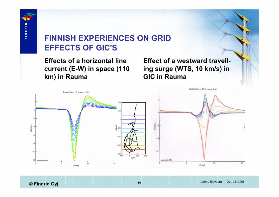
FINNISH EXPERIENCES ON GRID EFFECTS OF GIC'SEffects of a horizontal line current (E-W) in space (110 km) in Rauma
Effect of a westward travell-ing surge (WTS, 10 km/s) in GIC in Rauma

17 Jarmo Elovaara Oct. 25, 2005© Fingrid Oyj
FINNISH EXPERIENCES ON GRID EFFECTS OF GIC'S
Geoelectric field (arrows) and GIC (circles) distribution in events on 1995-04-07-16:47UT and 1998-05-04-05:32 UT
18 Jarmo Elovaara Oct. 25, 2005© Fingrid Oyj
FINNISH EXPERIENCES ON GRID EFFECTS OF GIC'SAbout the available models:
models based on realistic ionospheric current models and spatially inhomogeneous geoelectric fieldsrealistic inhomogeneous multi-layer earth models appliedgeoelectric field calculated directly from magnetic data of BEAR and IMAGE magnetometer arrays, 161 cases, 11 with K-index 9, 20 with K=8 (worst case not seen yet?!)the registration network is not dense enough to cover well all parts of Finlandfour events causing maximum GIC's analysed in detailgeoelectric field distributions vary greatly from event to event and so does the correlation of GIC's through transformersΣIGIC > 2000 A (400 & 220 kV) occurs 4 times in one 11-year sunspot cycle, largest currents in Alajärvi (237 A) and Kristiina (188 A)GIC is large in regions with poor conductivity of the earth
19 Jarmo Elovaara Oct. 25, 2005© Fingrid Oyj
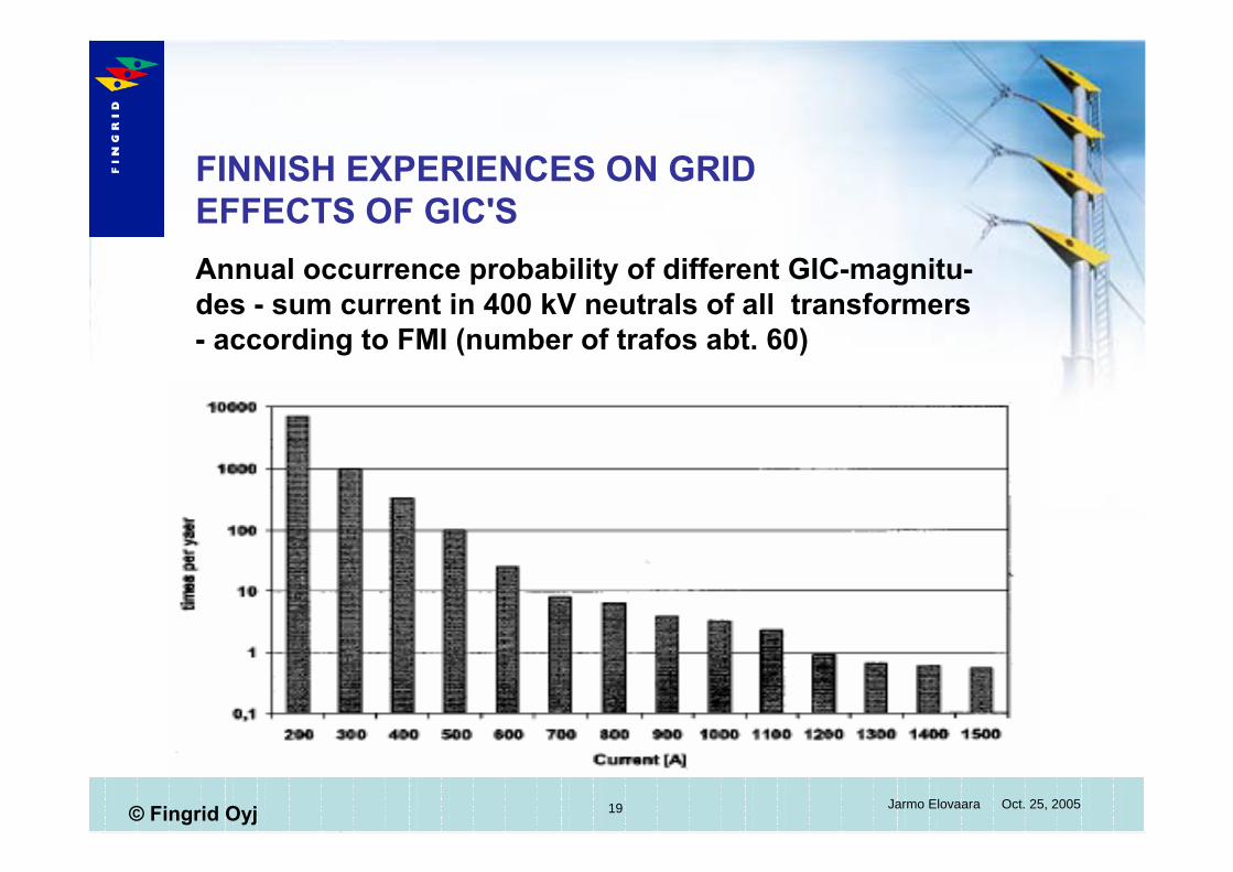
FINNISH EXPERIENCES ON GRID EFFECTS OF GIC'SAnnual occurrence probability of different GIC-magnitu-des - sum current in 400 kV neutrals of all transformers - according to FMI (number of trafos abt. 60)

20 Jarmo Elovaara Oct. 25, 2005© Fingrid Oyj
FINNISH EXPERIENCES ON GRID EFFECTS OF GIC'SAnnual occurrence probabilities of different GIC-mag-nitudes in Rauma transformer 400 kV neutral according to FMI (situation 1999)
21 Jarmo Elovaara Oct. 25, 2005© Fingrid Oyj
FINNISH EXPERIENCES ON GRID EFFECTS OF GIC'S
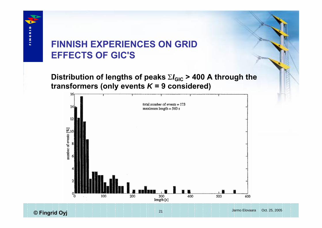
Distribution of lengths of peaks ΣIGIC > 400 A through the transformers (only events K = 9 considered)
22 Jarmo Elovaara Oct. 25, 2005© Fingrid Oyj
FINNISH EXPERIENCES ON GRID EFFECTS OF GIC'S
Finnish and Nordic transmission grid experiences during GIC-events
up to 2003 GIC's had caused none disturbance nor equipment failure in Finland although the neutral currents have been highin 2003 in Finnish Lapland one protective relay caused an erroneous tripping because the relay had been configured erroneously; harmonic content of the current caused the erroneous tripping, the Finnish transformers have not overheated during the GIC events nor have they produced gas during these events
23 Jarmo Elovaara Oct. 25, 2005© Fingrid Oyj
FINNISH EXPERIENCES ON GRID EFFECTS OF GIC'S
in Sweden erratic tripping of sensitive earth-fault relays has taken place in several GIC-occasions
– electromechanical relays without harmonic blocking and with constant-time characteristic, some static relais too
– one this kind of event caused a black-out in city of Malmö in October 2003 (too sensitive relay = too low tripping value)
certain transformers are in Sweden of the "GIC-sensitive type" and the operators are worried about the behaviour of these transformers
– Note 1: In USA and UK transformer failures have occurred– Note 2: in Canada the tripping of the Static Var Systems due
to the GIC caused a black-out in the Hydro Quebec -system in 1989 (reactive power unbalance)

24 Jarmo Elovaara Oct. 25, 2005© Fingrid Oyj
In Sweden GIC's have also caused "unstable" operation of generator voltage controllers and in certain occasions series capacitors have been blocked due to the incorrect operation of their protection systems HVDC-links between the Nordic countries as well as the one connecting the Finnish grid to the Russian grid have not been disturbed due to GICGASUM (the Finnish natural gas distribution company) is worried about the risk that GIC's deteriorate the corrosion protection system of the buried gas pipes
25 Jarmo Elovaara Oct. 25, 2005© Fingrid Oyj
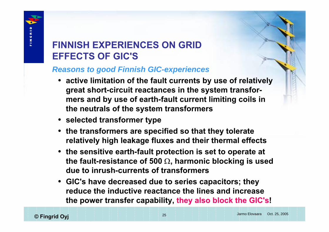
FINNISH EXPERIENCES ON GRID EFFECTS OF GIC'SReasons to good Finnish GIC-experiences
active limitation of the fault currents by use of relatively great short-circuit reactances in the system transfor-mers and by use of earth-fault current limiting coils in the neutrals of the system transformersselected transformer typethe transformers are specified so that they tolerate relatively high leakage fluxes and their thermal effectsthe sensitive earth-fault protection is set to operate at the fault-resistance of 500 Ω, harmonic blocking is used due to inrush-currents of transformersGIC's have decreased due to series capacitors; they reduce the inductive reactance the lines and increase the power transfer capability, they also block the GIC's!

26 Jarmo Elovaara Oct. 25, 2005© Fingrid Oyj
FINNISH EXPERIENCES ON GRID EFFECTS OF GIC'S
Fault current limitationthe selection of the transformer type is strongly connected with the fault current limitationthere might be the need to limit the magnitudes of the fault currents if the resistivity of the soil is too high (like in Finland); otherwise it would be too difficult (even impos-sible) and far too expensive to limit the ground potential rises during faults to safe values to people and animals=> increase the short-circuit and zero-seq. impedancesthe system transformers in Finland are of the three-phase, full-wound, five- or three-legged type with the short-circuit impedance of 20 % (the resistance is only abt. 0,3 %)

27 Jarmo Elovaara Oct. 25, 2005© Fingrid Oyj
FINNISH EXPERIENCES ON GRID EFFECTS OF GIC'S
Transformer type versus leakage reactance Xk, zero-sequence impedance Z0 and GIC-sensitivity ( = area avail. for DC flux return)
Transformer type Xk Z0/Xk GIC-sens
full-wound 3-ph, 3-leg core-form free 5 0full-wound 3-ph 5-leg core-form free ∞...1 0,24..0,33full-wound 1-ph, shell-form free 1 1,0autotrafo, 3-ph, shell-form ~ 0 1 0,5..0,67autotrafo, 1-ph, shell -form ~ 0 1 1,0
Fingrid has only full-wound three-phase core form transformers
28 Jarmo Elovaara Oct. 25, 2005© Fingrid Oyj
FINNISH EXPERIENCES ON GRID EFFECTS OF GIC'S
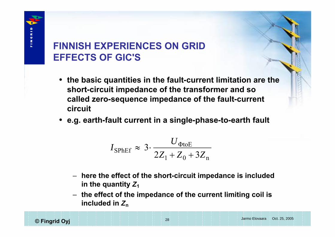
the basic quantities in the fault-current limitation are the short-circuit impedance of the transformer and so called zero-sequence impedance of the fault-current circuite.g. earth-fault current in a single-phase-to-earth fault
– here the effect of the short-circuit impedance is included in the quantity Z1
– the effect of the impedance of the current limiting coil is included in Zn
n01
ΦtoESPhEf 32
3ZZZ
UI
++⋅≈
29 Jarmo Elovaara Oct. 25, 2005© Fingrid Oyj
FINNISH EXPERIENCES ON GRID EFFECTS OF GIC'S
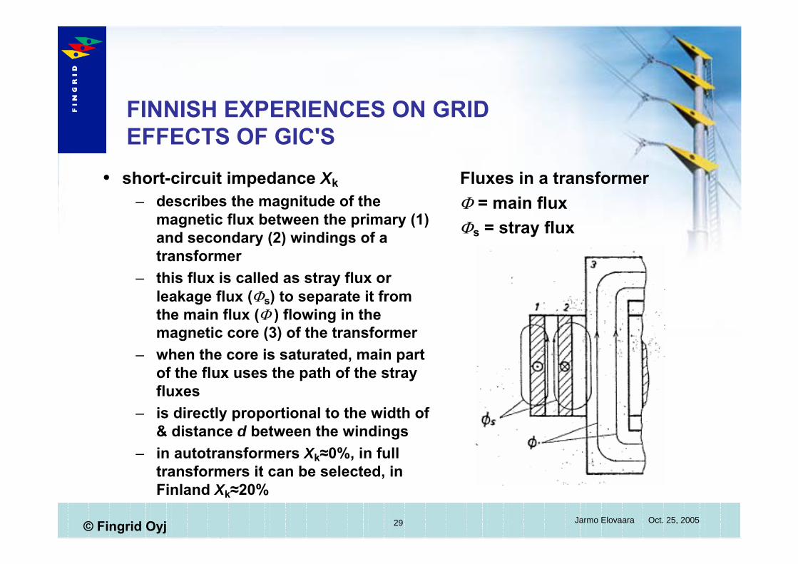
short-circuit impedance Xk– describes the magnitude of the
magnetic flux between the primary (1) and secondary (2) windings of a transformer
– this flux is called as stray flux or leakage flux (Φs) to separate it from the main flux (Φ ) flowing in the magnetic core (3) of the transformer
– when the core is saturated, main part of the flux uses the path of the stray fluxes
– is directly proportional to the width of & distance d between the windings
– in autotransformers Xk≈0%, in full transformers it can be selected, in Finland Xk≈20%
Fluxes in a transformerΦ = main fluxΦs = stray flux
30 Jarmo Elovaara Oct. 25, 2005© Fingrid Oyj
FINNISH EXPERIENCES ON GRID EFFECTS OF GIC'S
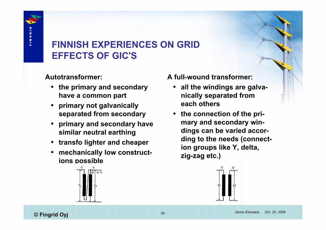
Autotransformer:the primary and secondary have a common partprimary not galvanically separated from secondaryprimary and secondary have similar neutral earthingtransfo lighter and cheapermechanically low construct-ions possible
A full-wound transformer:all the windings are galva-nically separated from each othersthe connection of the pri-mary and secondary win-dings can be varied accor-ding to the needs (connect-ion groups like Y, delta, zig-zag etc.)
31 Jarmo Elovaara Oct. 25, 2005© Fingrid Oyj
FINNISH EXPERIENCES ON GRID EFFECTS OF GIC'SShort-circuit impedance
due to the value Xk = 20 % the internal construction and materials to be used in the transformers in Finland have been selected according to high leakage fluxesleakage flux generates eddy currents and heat in metallic parts (in autotransformers no need to pay attention to this flux)further, the Fingrid's transformer specifications require in addition to the standard heat-run tests also two separate additional thermal tests as a type test:
– a test for the 400/110 kV winding pair with the primary current 1,5•IN1 so that hottest spot of the winding reaches 140 oC and thereafter this temperature is maintained 8 h
– a corresponding test required to tertiary winding, too
32 Jarmo Elovaara Oct. 25, 2005© Fingrid Oyj
FINNISH EXPERIENCES ON GRID EFFECTS OF GIC'S
during the additional thermal tests the temperature rise of the windings, iron core,structural parts and transformer tank are monitored with the help of thermo-optical sen-sors connected to optical fibres, with conventional ther-mo-couples and by IR-scanning the tankas a whole, these additional tests have been very usefullduring GIC-events these additional tests have turned out to be important because in the saturated transformer a major part of the main flux takes the path of the stray flux (in normal operation conditions the transformers work with a main flux density 1,8 T which is about 80 % of the value where saturation starts to occur)
33 Jarmo Elovaara Oct. 25, 2005© Fingrid Oyj
FINNISH EXPERIENCES ON GRID EFFECTS OF GIC'S
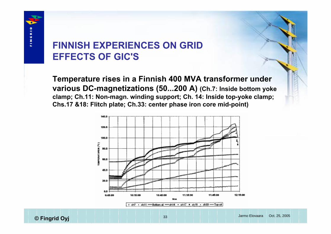
Temperature rises in a Finnish 400 MVA transformer under various DC-magnetizations (50...200 A) (Ch.7: Inside bottom yoke clamp; Ch.11: Non-magn. winding support; Ch. 14: Inside top-yoke clamp; Chs.17 &18: Flitch plate; Ch.33: center phase iron core mid-point)
34 Jarmo Elovaara Oct. 25, 2005© Fingrid Oyj
FINNISH EXPERIENCES ON GRID EFFECTS OF GIC'S
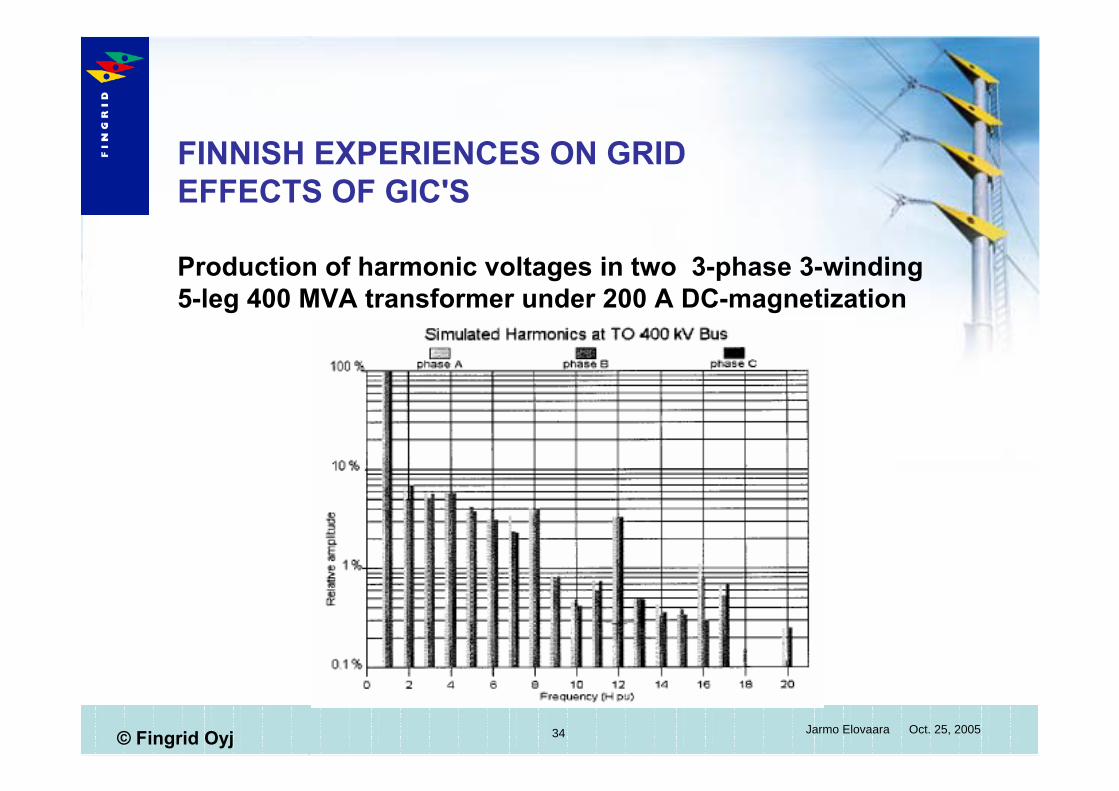
Production of harmonic voltages in two 3-phase 3-winding 5-leg 400 MVA transformer under 200 A DC-magnetization
35 Jarmo Elovaara Oct. 25, 2005© Fingrid Oyj
FINNISH EXPERIENCES ON GRID EFFECTS OF GIC'S
Note!the GIC through an earthed transformer is significantly greater than the 50 Hz magnetization current of the transformer (for a 400 MVA transformer typically of the order of 2...3 A, i.e. 0,3...0,4 % of rated primary current)because the GIC is a pseudo-stationary current, it must not be compared directly with the magnetization current!when the magnetization effect of the GIC is studied, the voltage drop, which the GIC causes in the winding, has to be taken into account together with the hysteresis loop of the saturated transformer (otherwise incorrect conclu-sions; e.g. magnetization current reaches also values <0)
36 Jarmo Elovaara Oct. 25, 2005© Fingrid Oyj
FINNISH EXPERIENCES ON GRID EFFECTS OF GIC'S
Finnish transformers and GIC's:highest temperature 130 oC measured but in favourable climatic conditions (ambient temp. -2 oC)highest temperature rise (∆T) about 110 Ktime constant of this temperature rise about 10 minif transformer is, at a start of an GIC-event, already in normal load with high ambient temperature, internal temperatures 170...180 oC can be reached => No risk because no cellulose material in the vicinitysome gassing of oil might occur, even gas bubbles, but the risk is low (200 A appr. 1 time per 50 years)winding temperatures do not reach critical values

37 Jarmo Elovaara Oct. 25, 2005© Fingrid Oyj
FINNISH EXPERIENCES ON GRID EFFECTS OF GIC'SGIC's and the Finnish grid:
in weak points of the system the distortion level of the voltages can be very severethe possibility of component failures is not excludedvoltage control problems a potential risk , too
– one transformer consumes abt. 55 Mvar at 200 A DC-magnetisation
– ΣIGI=1200 A would require extra reactive power capacity of 660 Mvar => abt. 95 % of time there is enough reactive power resources available <=> one voltage collapse per 20 a
the GIC's are becoming smaller due to the evolution of the grid (e.g. series compensation of longer lines with series capacitor banks)Risks acceptable; no mitigation, no warning systems

38 Jarmo Elovaara Oct. 25, 2005© Fingrid Oyj
FINNISH EXPERIENCES ON GRID EFFECTS OF GIC'SCurrent limiting coils in transformer neutrals
The impedance in the neutral branch is 3 times as "effective" than in phasesThe 400 kV winding neutral point coils
– are of air-core type and – have typically reactance of 120 Ω
and resistance of 2,4 Ωthe resistance of the neutral branch does not affect in the losses and its value can be selected on the basis of the thermal aspectsthe resistance 3*2,4 Ω has a significant magnitude when compared to the typical zero-sequence resistance of a 400 kV overhead line (r0 = 0,067...0,075 Ω/km) and transformers (0,3 Ω) and has importance in limiting the GIC in the grid
39 Jarmo Elovaara Oct. 25, 2005© Fingrid Oyj
FINNISH EXPERIENCES ON GRID EFFECTS OF GIC'S
About the future:no special measures needed if the dimensioning principles and equipment kept similar as nowif large single-phase transformers will be installed in the grid, mitigation methods might become necessary
– capacitor between the earth and the neutral of the transformer, or
– use of a resistor in series with the current limiting coilreactive power reserves of the grid shall be maintainedthe equipments should withstand high harmonic voltages and currents (esp. protective relais worth of special consideration)