finley solar farm
TRANSCRIPT

SLR Ref: 620.13767-R01 Version No: -v1.0 April 2020
FINLEY SOLAR FARM
Reflective Glare Assessment
Prepared for:
KDC Suite 2B, 125 Bull Street
NEWCASTLE WEST NSW 2302

KDC Finley Solar Farm Reflective Glare Assessment
SLR Ref No: 620.13767-R01-v1.0.docx April 2020
Page 2
PREPARED BY
SLR Consulting Australia Pty Ltd ABN 29 001 584 612 Tenancy 202 Submarine School, Sub Base Platypus, 120 High Street North Sydney NSW 2060 Australia T: +61 2 9427 8100 E: [email protected] www.slrconsulting.com
BASIS OF REPORT
This report has been prepared by SLR Consulting Australia Pty Ltd with all reasonable skill, care and diligence, and taking account of the timescale and resources allocated to it by agreement with KDC (the Client). Information reported herein is based on the interpretation of data collected, which has been accepted in good faith as being accurate and valid.
This report is for the exclusive use of the Client. No warranties or guarantees are expressed or should be inferred by any third parties. This report may not be relied upon by other parties without written consent from SLR
SLR disclaims any responsibility to the Client and others in respect of any matters outside the agreed scope of the work.
DOCUMENT CONTROL
Reference Date Prepared Checked Authorised
620.13767-R01-v1.0 29 April 2020 Dr Peter Georgiou Dr Neihad Al-Khalidy Dr Neihad Al-Khalidy

KDC Finley Solar Farm Reflective Glare Assessment
SLR Ref No: 620.13767-R01-v1.0.docx April 2020
EXECUTIVE SUMMARY
Page 3
SLR Consulting Australia Pty Ltd (SLR) has been engaged by KDC to carry out a Reflective Glare assessment of the proposed Finley Solar Farm (the “Project”) under development by Providence Asset Group. The Project is located close to Finley, NSW, approximately 2.5 km southwest of Finley town centre and 1.5 km from the nearest Finley suburbs. Finley Airport is located just over 1 km to the southeast.
The proposed (up to) 5 MWac facility will comprise 14,196 solar PV panels within a 15 ha project site area. The 425 W panels, measuring 2.2 m by 1.0 m, will be positioned as currently understood on single-axis trackers oriented north-south with a spacing of 7 m.
Section 2 describes the footprint and envelope of the proposed Finley Solar Farm.
The following potential glare conditions have been considered:
• Daytime Reflective glare (and glint) arising from the solar PV panels within the facility
• Night-time Illumination glare from 24/7 operational security lighting within the facility
In terms of potential glare scenarios, the following has been considered:
• Aviation Sector Reflective Glare;
• Motorist “Disability” Reflective Glare and Pedestrian “Discomfort” Reflective Glare;
• Rail Operator Reflective Glare;
• Industrial critical machinery operators (heavy vehicles, etc) Reflective Glare; and
• Residential “Nuisance” Glare from daytime reflections or night-time illumination.
In all cases, the present study has found that the potential for adverse glare from the proposed facility will be negligible, due to a combination of factors, including:
• The choice of a single axis tracking mounting system and the distances to nearest receivers of interest in relation to aviation, road traffic, rail traffic and residential.
To avoid the potential for potential glare occurrences at Finley Airport for the theoretical “Zero” Tilt scenario, ie any situation where the tilting action of the solar array is disabled (eg maintenance works, etc), it is recommended that panels should not be left horizontal in such circumstances, but be left tilted to the west, ideally at a tilt angle of at least 10° to horizontal.
There should be negligible impact if 24/7 lighting is required on the site for operational purposes, assuming the lighting design is in accordance with AS 4282-1997 Control of the Obtrusive Effect of Outdoor Lighting. This would also address any potential adverse eco-lighting issues in relation to nocturnal fauna within and surrounding the site, although, as far as is known, no biodiversity issues have been identified in relation to the Project.
When key Project decisions are finalised during detailed design (eg final panel selection, mounting details, etc), the present analysis should be re-visited to confirm the conclusions set out above if key assumptions made in the analysis change significantly.

KDC Finley Solar Farm Reflective Glare Assessment
SLR Ref No: 620.13767-R01-v1.0.docx April 2020
CONTENTS
Page 4
1 INTRODUCTION ........................................................................................................... 7
1.1 Structure of Report ...................................................................................................... 7
2 PROPOSED FINLEY SOLAR FARM PROJECT ................................................................... 8
2.1 Site Location ................................................................................................................ 8
2.2 Site Description and Key Project Components .............................................................. 9
3 RECEIVERS AND ASSOCIATED IMPACTS ..................................................................... 11
3.1 Receiver Impacts ........................................................................................................ 11
3.2 Nearest Receiver Locations ........................................................................................ 11
4 GLARE ACCEPTABILITY CRITERIA................................................................................ 14
4.1 Aviation Sector Reflective Glare ................................................................................. 14
4.2 Motorist “Disability” Glare and Pedestrian “Discomfort” Glare................................... 15
4.3 Rail Operators Reflective Glare ................................................................................... 16
4.4 Residential “Nuisance” Glare ...................................................................................... 16
4.5 Industrial Critical Machinery Operations .................................................................... 16
4.6 Night-Time Illumination Glare .................................................................................... 17
5 GLARE IMPACT ASSESSMENT - ASSUMPTIONS .......................................................... 19
5.1 Assumptions – Solar Panel Geometry ......................................................................... 19
5.2 Project Site Solar Angles – Annual Variations.............................................................. 19
5.3 Project Solar Reflections ............................................................................................ 20
5.4 Solar Panel Reflectivity ............................................................................................... 21
6 GLARE IMPACT ASSESSMENT - RESULTS .................................................................... 23
6.1 Aviation Sector Reflective Glare ................................................................................. 23
6.2 Motorist “Disability” Glare and Pedestrian ‘Discomfort” Glare ................................... 26
6.3 Rail Operator Reflective Glare .................................................................................... 28
6.4 Industrial Critical Machinery Operators ...................................................................... 28
6.5 Residential “Nuisance” Glare ...................................................................................... 28
6.6 Night-Time Illumination Glare .................................................................................... 29
7 CONCLUSION ............................................................................................................. 30
KDC Finley Solar Farm Reflective Glare Assessment
SLR Ref No: 620.13767-R01-v1.0.docx April 2020
CONTENTS
Page 5
DOCUMENT REFERENCES
TABLES
Table 1 Typical Illuminance Levels for Various Scenarios ...................................................... 17 Table 2 Recommended Maximum Values of Light Technical Parameters (AS4282-1997) ...... 18 Table 3 Key Annual Solar Angle Characteristics for Project Site ............................................ 19 Table 4 SGHAT Analysis Results ( No of Minutes Reflections are in SGHAT Zones ) ............... 25 Table 5 TI Value Results – Combined Results from ALL PROJECT SOLAR PANELS ................... 26 Table 6 TI Value Results – Residential Receivers ................................................................... 28
FIGURES
Figure 1 Finley Solar Farm - Location Map ............................................................................... 8 Figure 2 Finley Solar Farm Site Layout ..................................................................................... 9 Figure 3 Nearest Airfields to Project Site ............................................................................... 12 Figure 4 Surrounding Road Network...................................................................................... 12 Figure 5 Surrounding Rail Network and NSW Rail Map .......................................................... 13 Figure 6 Nearest Representative Residential (RR) Receivers .................................................. 13 Figure 7 Example Solar Glare Ocular Plot (SGHAT Software Output) ...................................... 15 Figure 8 Project Site Incoming Solar Angle Variations ............................................................ 20 Figure 9 Potential Solar PV Panel Reflection Angles from the Project (typical mid-
summer) .................................................................................................................. 21 Figure 10 Typical Reflectivity Curves as a Function of Incidence Angle ..................................... 22 Figure 11 Flight Path Geometry for SGHAT Analysis (Aircraft and Helicopters) ........................ 23 Figure 12 View of the Project from Surrounding Roads ........................................................... 27 Figure 13 Luminaire Design Features that Minimise Light Spill................................................. 29
APPENDICES
Appendix A SGHAT Ocular Plot Analysis Results

KDC Finley Solar Farm Reflective Glare Assessment
SLR Ref No: 620.13767-R01-v1.0.docx April 2020
Page 6
Abbreviations and Definitions
Terms relevant to Daytime Reflective Glare
PV Panel Photovoltaic (PV) panels are designed to absorb solar energy and retain as much of the solar spectrum as possible in order to produce electricity
Glare Glare refers to the reflections of the sun off any reflective surface, experienced as a source of excessive brightness relative to the surrounding diffused lighting. Glare covers reflections experienced by both stationary and moving observers (the latter sometimes referred to as “glint”) and reflections which are either specular or diffuse.
Specular A reflection which is essentially mirror-like – there is virtually no loss of intensity or angle dispersion between the incoming solar ray and outgoing reflection
Diffuse A reflection in which the outgoing reflected rays are dispersed over a wide (“diffuse”) range of angle compared to the incoming (parallel) solar rays, typical of “rougher” surfaces
KVP Key View Points (KVPs) are offsite locations where receivers of interest have the potential to experience adverse reflective glare
Terms relevant to Night-Time Illumination
Spill light Light emitted by a lighting installation, which subsequently falls outside the boundaries of the property on which the installation is sited.
Obtrusive light Spill light which, because of quantitative, directional or spectral attributes in a given context, gives rise to annoyance, discomfort, distraction or a reduction in the ability to see essential information, eg traffic lights.
Luminaire Apparatus which distributes, filters or transforms the light transmitted from one or more lamps and which includes, except for the lamps themselves, all the parts necessary for fixing and protecting the lamps and, where necessary circuit auxiliaries together with the means for connecting them to the electrical supply.
Luminous intensity The concentration of luminous flux emitted in a specific direction. Unit: candela (Cd).
Luminance AS 1158.2:2005
This is the physical quantity corresponding to the brightness of a surface (e.g. a lamp, luminaire or reflecting material such as façade glazing) when viewed from a specified direction. Unit: Cd/m2
Illuminance AS 1158.2:2005
This is the physical measure of illumination. It is the luminous flux arriving at a surface divided by the area of the illuminated surface – the unit is lux (lx) … 1 lx = 1 lm/m2
The term covers both “Horizontal Illuminance” (the value of illuminance on a designated horizontal plane at ground level) and “Vertical Illuminance” (the value of illuminance on a designated vertical plane at a height of 1.5m above ground level).
Glare AS 1158.2:2005
Condition of vision in which there is a discomfort or a reduction in the ability to see, or both, caused by an unsuitable distribution or range of luminance, or to extreme contrast in the field of vision. Glare can include:
(a) Disability Glare – glare that impairs the visibility of objects without necessarily causing discomfort.
(b) Discomfort Glare – glare that causes discomfort without necessarily impairing the visibility of objects.
Threshold Increment (TI)
AS 4282-1997
TI is the measure of disability glare expressed as the percentage increase in contrast required between an object and its background for it to be seen equally well with a source of glare present.
Higher TI values correspond to greater disability glare.

KDC Finley Solar Farm Reflective Glare Assessment
SLR Ref No: 620.13767-R01-v1.0.docx April 2020
Page 7
1 INTRODUCTION
SLR Consulting Australia Pty Ltd (SLR) has been engaged by KDC to carry out a Reflective Glare assessment of the proposed Finley Solar Farm (the “Project”) under development by Providence Asset Group. The Project is located close to Finley, NSW, approximately 2.5 km southwest of Finley town centre and 1.5 km from the nearest Finley suburbs.
The following potential glare conditions have been considered:
• Daytime Reflective glare (and glint) arising from the solar PV panels within the facility
• Night-time Illumination glare from 24/7 operational security lighting within the facility
1.1 Structure of Report
The remainder of this report is structured as follows:
• Section 2 describes the Project and surrounding environment;
• Section 3 describes the range of receptors surrounding the site with the potential to experience adverse reflective glare (or glint);
• Section 4 presents the acceptability criteria used for the study;
• Section 5 addresses the assumptions made in the glare impact analysis;
• Section 6 presents the results of the glare impact analysis of the Project;
• Section 7 presents the conclusions of the study.

KDC Finley Solar Farm Reflective Glare Assessment
SLR Ref No: 620.13767-R01-v1.0.docx April 2020
Page 8
2 PROPOSED FINLEY SOLAR FARM PROJECT
2.1 Site Location
The Project is seeking approval for an (up to) 5 MWac photovoltaic (PV) solar plant occupying a 15 ha area as shown in Figure 1. The Project is located close to Finley, NSW, approximately 2.5 km southwest of Finley town centre and 1.5 km from the nearest Finley suburbs. Finley Airport is located just over 1 km to the southeast.
The land required for the Project has been subject to constraints identified by site investigation, i.e. native vegetation, and areas of cultural or heritage significance. The plan of the Project has been developed following completion of these site investigations and the assessment of any constraints and their impact.
Figure 1 Finley Solar Farm - Location Map
Tocumwal Railway Line ( closed )
Finley
Finley Solar Farm
Finley Airport
Broockmanns Road
Riverina Highway
Newell Highway
Riverina Highway
Dales Road

KDC Finley Solar Farm Reflective Glare Assessment
SLR Ref No: 620.13767-R01-v1.0.docx April 2020
Page 9
2.2 Site Description and Key Project Components
From a Reflective Glare point of view, the key components of the Project are:
• the photovoltaic (PV) modules in relation to their daytime reflective glare potential; and
• the facility’s security/emergency lighting design in relation to potential night-time illumination glare issues (if such 24/7 lighting is incorporated into the Project).
Solar Panel Mounted Array – refer Figure 2
The proposed ground-mounted array (refer Figure 2(a)) would consist of 182 trackers oriented in a north-south direction, each supporting 78 x 425W solar panels (14,196 panels in total);
• The trackers are “single-axis” capable of rotating solar panels to a maximum of ±60° - refer Figure 2(b);
• The trackers are oriented north-south and spaced 7 m apart; and
• Individual panels (2.2 m x 1.0 m) reach a maximum height above ground of 2.73 m at their full 60° tilt angle;
• The northern perimeter of the Project lies approximately 700 m from Broockmanns Road (to the north) with the eastern perimeter 650 m from Dales Road (to the east); the eastern-most tracker is located approximately 1.7 km from the nearest major thoroughfare, the Newell Highway.
Figure 2 Finley Solar Farm Site Layout
(a) Site Layout
Broockmanns Road to the
North
Solar PV Panels Single-Axis Trackers
Dales Road to the East
Access Road to Broockmanns
Road

KDC Finley Solar Farm Reflective Glare Assessment
SLR Ref No: 620.13767-R01-v1.0.docx April 2020
Page 10
Fig.2 (cont’d)
(b) Single-Axis Tracker Profile ( ±60° Tilt )
KDC Finley Solar Farm Reflective Glare Assessment
SLR Ref No: 620.13767-R01-v1.0.docx April 2020
Page 11
3 RECEIVERS AND ASSOCIATED IMPACTS
3.1 Receiver Impacts
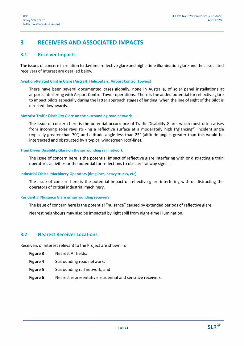
The issues of concern in relation to daytime reflective glare and night-time illumination glare and the associated receivers of interest are detailed below.
Aviation-Related Glint & Glare (Aircraft, Helicopters, Airport Control Towers)
There have been several documented cases globally, none in Australia, of solar panel installations at airports interfering with Airport Control Tower operations. There is the added potential for reflective glare to impact pilots especially during the latter approach stages of landing, when the line of sight of the pilot is directed downwards.
Motorist Traffic Disability Glare on the surrounding road network
The issue of concern here is the potential occurrence of Traffic Disability Glare, which most often arises from incoming solar rays striking a reflective surface at a moderately high (“glancing”) incident angle (typically greater than 70˚) and altitude angle less than 25˚ (altitude angles greater than this would be intersected and obstructed by a typical windscreen roof-line).
Train Driver Disability Glare on the surrounding rail network
The issue of concern here is the potential impact of reflective glare interfering with or distracting a train operator’s activities or the potential for reflections to obscure railway signals.
Industrial Critical Machinery Operators (draglines, heavy trucks, etc)
The issue of concern here is the potential impact of reflective glare interfering with or distracting the operators of critical industrial machinery.
Residential Nuisance Glare on surrounding receivers
The issue of concern here is the potential “nuisance” caused by extended periods of reflective glare.
Nearest neighbours may also be impacted by light spill from night-time illumination.
3.2 Nearest Receiver Locations
Receivers of interest relevant to the Project are shown in:
Figure 3 Nearest Airfields;
Figure 4 Surrounding road network;
Figure 5 Surrounding rail network; and
Figure 6 Nearest representative residential and sensitive receivers.

KDC Finley Solar Farm Reflective Glare Assessment
SLR Ref No: 620.13767-R01-v1.0.docx April 2020
Page 12
Figure 3 Nearest Airfields to Project Site
Figure 4 Surrounding Road Network
Finley Solar Farm
1,100 m
Finley Airport
Runway 05/23
Finley Solar Farm
Broockmanns Road
Riverina Highway
Newell Highway
Riverina Highway
Dales Road
1 km
05
23

KDC Finley Solar Farm Reflective Glare Assessment
SLR Ref No: 620.13767-R01-v1.0.docx April 2020
Page 13
Figure 5 Surrounding Rail Network and NSW Rail Map
Figure 6 Nearest Representative Residential (RR) Receivers
RR5
RR1
RR2
RR3
RR4
Finley Solar Farm
Tocumwal Railway Line
Finley Solar Farm
1 km
RR6

KDC Finley Solar Farm Reflective Glare Assessment
SLR Ref No: 620.13767-R01-v1.0.docx April 2020
Page 14
4 GLARE ACCEPTABILITY CRITERIA
In relation to daytime reflective glare impact, the Project contains the following elements of interest:
• PV modules using solar panels on the Project ground array;
In relation to night-time illumination glare impact, the Project may, in the future, include the following elements of interest:
• 24/7 lighting for access roads to enable site maintenance, fire and other emergency events, and 24/7 lighting for the on-site Operations & Maintenance building and power conversion unit which provide connection to the local distribution network.
Night-time illumination is not presently incorporated in the current Project design.
4.1 Aviation Sector Reflective Glare
The impact of solar PV systems on aviation activity is something that solar developers today are addressing more and more often, given the (global) proliferation of solar projects, in particular those located either within or around airport precincts.
Guidance in this area is available from two sources – UK CAA and US FAA.
US FAA
The reader is referred to the following technical references:
• Brumleve (various, 1976-1984), Ho, Ghanbari & Diver (2009, 2010) and Ho & Khalsa (2010)
The FAA regulates and oversees all aspects of American civil aviation. On the basis of the above and other technical R&D references, the FAA issued a Technical Guidance Policy in 2010 and a subsequent (and over-riding) Interim Policy in 2013. The Technical Guidance Policy was updated in 2018.
• FAA, “Technical Guidance for Evaluating Selected Solar Technologies on Airports”, Federal Aviation Administration, Washington, D.C., November 2010.
• FAA, “Interim Policy, FAA Review of Solar Energy System Projects on Federally Obligated Airports” Federal Register, Oct. 23, 2013,
• FAA, “Technical Guidance for Evaluating Selected Solar Technologies on Airports”, Federal Aviation Administration, Washington, D.C., Version 1.1, April 2018.
In support of the above, the FAA contracted Sandia Labs to develop their Solar Glare Hazard Analysis Tool (SGHAT) software as the standard tool for measuring the potential ocular impact of any proposed solar facility on a federally obligated airport. SGHAT utilises the Solar Glare Ocular Hazard Plot to determine and assess the potential for glare. SGHAT is described in the following references:
• Ho, C.K., Ghanbari, C.M. and Diver, R.B.,, “Methodology to Assess Potential Glint and Glare Hazards from Concentrating Solar Power Plants: Analytical Models and Experimental Validation”, J. Solar Engineering, August 2011, Vol.133, 031021-1 to 031021-9.
• Ho, C.K. & Sims, C., “Solar Glare Hazard Analysis Tool (SGHAT) User’s Manual v2.0”, Sandia National Laboratories, Albuquerque, NM. August 2013.

KDC Finley Solar Farm Reflective Glare Assessment
SLR Ref No: 620.13767-R01-v1.0.docx April 2020
Page 15
A sample Solar Glare Ocular Hazard Plot is shown in Figure 7 along with reference sources which contributed to the delineation of various hazard “zones”. The SGHAT criteria state that a proposed solar facility should satisfy the following:
• Airport Traffic Control Tower (ATCT) cab NO Glare
• Final approach paths for landing aircraft Glare to NOT exceed “Low Potential for After-Image”
The criteria also state:
• Ocular impact must be examined over the entire calendar year in 1-minute intervals, sunrise to sunset;
• Both existing and planned ATCT cabs should be examined for potential glint and glare; and
• Both existing and planned landing thresholds should be examined for potential glint and glare.
Figure 7 Example Solar Glare Ocular Plot (SGHAT Software Output)
4.2 Motorist “Disability” Glare and Pedestrian “Discomfort” Glare
The criteria commonly used by Local Government Authorities to assess the acceptability or otherwise of road traffic glare events utilise the so-called Threshold Increment (TI) Value of the reflection condition (refer Abbreviations and Definitions). These acceptability criteria were originally developed to address adverse reflections from the glass curtain wall façade systems of medium and high-rise buildings located close to road carriageways.
• For (Motorist) Traffic Disability Glare, the TI Value should remain:
• Below 10 for major roads
• Below 20 for minor roads
• For Pedestrian Discomfort Glare, the TI Value should remain:
• Below 2 at critical locations such as pedestrian crossings
• Below 3 for other locations
The TI Value is calculated as the ratio of “veiling” luminance to the overall average carriageway luminance, with the necessary constant and exponent parameters provided in AS 1158.2:2005.

KDC Finley Solar Farm Reflective Glare Assessment
SLR Ref No: 620.13767-R01-v1.0.docx April 2020
Page 16
4.3 Rail Operators Reflective Glare
Almost all Australian Rail Authorities have guidelines covering glare in general (ie not specific to solar PV panel glare) aimed at avoiding discomfort/distraction to train operators and obscuring train signals. Most guidelines refer either to Table 2.10 of AS 1158.3.1 for the TI Value criterion and/or Table 3.2 of AS 1158.4 for the Cd (Candela) criterion associated with the control of glare.
• For Rail Traffic Disability Glare, the relevant AS1158 criteria are:
• The TI Value should remain below 20%
• The Cd Value at 70˚ incidence should remain below 6,000.
4.4 Residential “Nuisance” Glare
Instances of documented nuisance glare associated with solar PV panels (grid-scale, industrial or residential) and nearby residential receivers have been relatively infrequent globally, especially given the widespread and rapid increase in the take-up of residential solar panels in Australia and elsewhere.
There are currently no national or state guidelines in Australia governing the acceptability or otherwise of nuisance glare specific to solar PV, although the concepts used for glare acceptability criteria in the preceding sections can assist when dealing with this issue.
Existing guidance that exists in relation to solar panels from state governments typically covers installation audits and compliance checks. Additional guidance in relation to compliance with Australia Standards is provided by:
Clean Energy Council website: www.cleanenergycouncil.org.au
4.5 Industrial Critical Machinery Operations
There are currently no (Australian) national or state guidelines governing the acceptability or otherwise of reflective glare for industrial site critical operations. Instead, the concepts used for acceptability criteria in the preceding sections, in particular Traffic Disability Glare, can assist when dealing with this issue.
The issue most commonly arises in relation to mining operations where machinery operators can be located in elevated locations, eg dragline operations, where a line of sight may be possible to a solar facility located in close proximity. Ports with their observation towers are another potential source of elevated receivers of interest if located adjacent to a solar facility.
No such industrial operations exist in the present case.

KDC Finley Solar Farm Reflective Glare Assessment
SLR Ref No: 620.13767-R01-v1.0.docx April 2020
Page 17
4.6 Night-Time Illumination Glare
The effect of light spill from outdoor lighting impacting on residents, transport users, transport signalling systems and astronomical observations is governed by AS 4282-1997.
The adverse effects of light spill from outdoor lighting are influenced by a number of factors:
• The topology of the area. Light spill is more likely to be perceived as obtrusive if the lighting installation is located higher up than the observer. Lighting installations are usually directed towards the ground and an observer could hence have a direct view of the luminaire.
• The surrounding area. Hills, trees, buildings, fences and general vegetation have a positive effect by shielding the observer from the light installation.
• Pre-existing lighting in the area. Light from a particular light source is seen as less obtrusive if it is located in an area where the lighting levels are already high, eg in cities. The same lighting installation would be seen as far more bothersome in a less well-lit residential area.
• The zoning of the area. A residential area is seen as more sensitive compared to commercial areas where high lighting levels are seen as more acceptable.
Typical illuminance levels for a variety of circumstances are given in Table 1 for comparison.
Table 1 Typical Illuminance Levels for Various Scenarios
Lighting Scenario Horizontal Illuminance (lux)
Moonless overcast night 0.0001
Quarter Moon 0.01
Full Moon 0.1
Twilight 10
Indoor office 300
Overcast day 1,000
Indirect sunlight clear day 10,000-20,000
Direct sunlight 100,000-130,000
Recommended criteria of light technical parameters for the control of obtrusive lighting are given in Table 2. The vertical illuminance limits for curfew hours apply in the plane of the windows of habitable rooms or dwellings on nearby residential properties. The vertical illuminance criteria for pre-curfew hours apply at the boundary of nearby residential properties in a vertical plane parallel to the boundary.
Values given are for the direct component of illuminance, i.e. no reflected light is taken into account.
• Limits for luminous intensity for curfew hours apply in directions where views of bright surfaces of luminaires are likely to be troublesome to residents, from positions where such views are likely to be maintained.
• Limits for luminous intensity for pre-curfew hours apply to each luminaire in the principal plane, for all angles at and above the control direction.

KDC Finley Solar Farm Reflective Glare Assessment
SLR Ref No: 620.13767-R01-v1.0.docx April 2020
Page 18
Table 2 Recommended Maximum Values of Light Technical Parameters (AS4282-1997)
Light Technical Parameter
Time of Operation
Commercial Areas
Residential Areas
Light Surrounds Dark Surrounds
Illuminance in vertical plane (Ev)
Pre-curfew hours 25 lx 10 lx 10 lx
Curfew hours 4 lx 2 lx 1 lx
Luminous Intensity emitted by luminaires (I)
Pre-curfew hours 7,500 Cd
(for a medium to large area with Level 1
control)
100,000 Cd
(for a large area with Level 1 control)
100,000 Cd
(for a large area with Level 1 control)
Curfew hours 2,500 Cd 1,000 Cd 500 Cd
The Project is located on the outskirts of Finley and has the potential to impact on surrounding residential properties – refer Figure 6. Some of these properties are not located within township environs proper and would therefore be classed as being in a residential area with “Dark Surrounds” - refer Table 2.
The applicable limits for adverse spill light will depend on the time of operation for the lighting installation.
For the Project, it is possible that internal access roads and any equipment buildings in particular, will be operational 24/7, suggesting the application of the more restrictive limit relevant to curfew hours.
Accordingly:
• Light spill from the Project onto the facades of the surrounding residential dwellings should be kept below 1 lux during curfew hours
Finally, it has been known for some time that night-time artificial lighting has the potential to disrupt the natural behaviour of nocturnal fauna species such as arboreal mammals, large forest owls and microbats. The standards mentioned above do not contain limiting lux levels in relation to the mitigation of such eco-lighting impacts.
Mitigation recommendations in relation to adverse eco-lighting therefore centre on feasible night-time lighting minimisation, bearing in mind the provision of appropriate health and safety and security conditions given the nature of the site. Biodiversity associated with the Project is discussed in the Flora and Fauna Assessment Report prepared for the Project. As far as is known, no adverse eco-lighting issues are apparent.

KDC Finley Solar Farm Reflective Glare Assessment
SLR Ref No: 620.13767-R01-v1.0.docx April 2020
Page 19
5 GLARE IMPACT ASSESSMENT - ASSUMPTIONS
The following potential glare conditions have been considered:
• Daytime Reflective glare (and glint) arising from the solar PV panels
• Night-time Illumination glare if any 24/7 operational security lighting is located within the site
5.1 Assumptions – Solar Panel Geometry
The glare assessment discussed in detail in following sections is based on the following assumptions:
• The solar panel array trackers are “single-axis” capable of rotating solar panels to a maximum of ±60°.
• The trackers are oriented north-south and spaced 7 m apart;
• Individual panels (2.2 m x 1.0 m) reach a maximum height above ground of 2.73 m at their full 60° tilt angle;
• The northern perimeter of the Project lies approximately 700 m from Broockmanns Road (to the north) with the eastern perimeter 650 m from Dales Road (to the east); the eastern-most tracker is located approximately 1.7 km from the nearest major thoroughfare, the Newell Highway.
5.2 Project Site Solar Angles – Annual Variations
One of the challenging issues encountered with daytime solar panel glare is the varying nature of the reflections, whose duration will vary with time of day and day of the year as the sun’s rays follow variable incoming angles between the two extremes of:
• summer solstice - sunrise incoming rays from just south of east, maximum angle altitude rays at midday, sunset incoming rays from just south of west
• winter solstice - sunrise incoming rays from the northeast, minimum angle altitude rays at midday, sunset incoming rays from the northwest
Any solar glare analysis must take into account the complete cycle of annual reflection variations noted above.
The potential range of incoming solar angles at the Project site relevant to daytime glare is shown in Figure 8 with relevant critical angles summarised in Table 3.
Table 3 Key Annual Solar Angle Characteristics for Project Site
Day of Year Sunrise Sunset Azimuth Range (sunrise-sunset) Max Altitude
Summer Solstice 5:07 am 7:32 pm 119° E of North to 119° W of North 77.6°
Equinox 6:23 am 6:26 pm 91° E of North to 91° W of North 54.9°
Winter Solstice 7:28 am 5:04 pm 61° E of North to 61° W of North 30.8°

KDC Finley Solar Farm Reflective Glare Assessment
SLR Ref No: 620.13767-R01-v1.0.docx April 2020
Page 20
Figure 8 Project Site Incoming Solar Angle Variations
5.3 Project Solar Reflections
The project will use single-axis tracking panels (with the axis of rotation oriented north-south) as described in Section 2.2. In “plan” view, reflections from the project’s panels will be directed as shown in Figure 9 for a representative area of panels, with the direction of reflected rays shown for typical mid-summer days.
As a result of the tracking motion of the solar panels throughout the day, reflections will generally be directed upwards and hence not visible by ground-based receivers. Where such reflections can be observed by surrounding elevated receivers they would be seen as “low incidence” reflections with corresponding low reflectivity. This is the inevitable outcome of the objective of maximising the solar gain of each panel (where the reflectivity would ideally be minimal) and justifying the additional cost of using a tracking system for the panels which follows the sun, rather than a fixed panel system.
0
10
20
30
40
50
60
70
80
90
3 6 9 12 15 18 21
Alt
itu
de
, d
eg
( 0
= H
ori
zon
, 9
0 =
Ve
rtic
al )
Time of Day ( "12" = Noon )
Finley Solar Farm21-Dec
21-Sep
21-Jun
-120
-90
-60
-30
0
30
60
90
120
3 6 9 12 15 18 21
Azi
mu
th,
deg
( -
90
= E
, 0
= N
, 9
0 =
W )
Time of Day ( "12" = Noon )
Finley Solar Farm
21-Dec
21-Sep
21-Jun

KDC Finley Solar Farm Reflective Glare Assessment
SLR Ref No: 620.13767-R01-v1.0.docx April 2020
Page 21
Figure 9 Potential Solar PV Panel Reflection Angles from the Project (typical mid-summer)
5.4 Solar Panel Reflectivity
Solar PV panels are designed to capture (absorb) the maximum possible amount of light within the layers below the front (external) surface. Consequently, solar PV panels are designed to minimise reflections off the surface of each panel. Reflections are a function of:
• the angle at which the light is incident onto the panel (which will vary depending on the specific location, time of day and day of the year), and
• the index of refraction of the front surface of the panel and associated degree of diffuse (non-directional) versus specular (directional or mirror-like) reflection which is a function of surface texture of the front module (reflecting) surface.
Some typical reflectivity values (given in terms of the “n” refractive index value) are:
• Snow (fresh, flaky) n = 1.98
• Standard Window Glass n = 1.52
• Plexiglass, Perspex n = 1.50
• Solar Glass n = 1.33
• Solar Glass with AR Coating n = 1.25
Mid-morning summer reflections
Mid-afternoon summer reflections
Midday reflections
Early morning summer reflections
Late afternoon summer reflections
All reflections pointed upwards
All reflections pointed upwards
] Standard PV Solar Panels

KDC Finley Solar Farm Reflective Glare Assessment
SLR Ref No: 620.13767-R01-v1.0.docx April 2020
Page 22
Representative reflectivity curves are shown in Figure 10.
Figure 10 Typical Reflectivity Curves as a Function of Incidence Angle
Figure 10 shows that:
• When an oncoming solar ray strikes the surface of a solar PV panel close to perpendicular to the panel surface (i.e. low “incident” angle), the reflectivity percentage is minimal (less than 5% for all solar panel surface types).
• It is only when an incoming solar ray strikes the panel at a large “incidence” angle, i.e. almost parallel to the panel, that reflectivity values increase. When this happens, reflections become noticeable and potentially at “glare” level for all solar panel surface types.
• However, for very high incidence angle, it would almost always be the case that the observer (motorist, train driver, pedestrian, etc) would perceive reflections coming from virtually the same direction as the incoming solar rays themselves. Such a condition would not constitute a glare situation as the intensity of the incoming solar ray itself would dominate the field of vision perceived by the observer.
Light striking perpendicular
to surface
Light striking almost parallel
to surface

KDC Finley Solar Farm Reflective Glare Assessment
SLR Ref No: 620.13767-R01-v1.0.docx April 2020
Page 23
6 GLARE IMPACT ASSESSMENT - RESULTS
6.1 Aviation Sector Reflective Glare
Finley Airport (IATA: FLY, ICAO: YFIL) is the nearest major airport. It is located approximately 1.1 km southeast of the Project. The airport is serviced by general aviation aircraft and helicopters.
• The airport has a single 900 m long asphalt Runway 05/23, oriented roughly northeast/southwest.
• The airport does not have a control tower.
Figure 11 shows (landing) flight paths of interest:
• Runway 05/23 is not in a direct line of sight towards the Project
• However, there would be potential for aircraft approaching the airport to have a curved flight track that would see them at least partially in a direct line of sight of the Project prior to their final approach path. This would be the case for example for aircraft flying in a westerly direction as they approach Finley, prior to banking left to land on Runway 23; similarly, aircraft flying in a northerly direction as they approach Finley, prior to banking right to land on Runway 05.
• Helicopter flight paths can be highly variable and landing approach paths in the direct line of sight of the Project are possible, although there is greater flexibility in adjusting helicopter flight paths if required.
Figure 11 Flight Path Geometry for SGHAT Analysis (Aircraft and Helicopters)
05 Worst-Case Helicopter Path
Finley Solar Farm
23
Runway 05/23
05C
23C
H

KDC Finley Solar Farm Reflective Glare Assessment
SLR Ref No: 620.13767-R01-v1.0.docx April 2020
Page 24
Accordingly, a quantitative analysis was carried out using the Sandia Labs Solar Glare Hazard Analysis Tool (SGHAT) software tool to examine potential worst-case scenario flight path approaches and take-offs and their ability to create adverse and unacceptable glare (and glint) conditions.
• The aircraft flight paths are all for landing scenarios (worst-case with the pilot looking downwards);
• The helicopter flight paths are for both landing and take-off in the same direction (as required by the SGHAT analysis protocol).
The flights paths assessed for the Project are shown in Figure 11.
In terms of the relative heights of flight paths and the solar farm:
• Ground elevations of Finley Solar Farm range from 109 m to 110 m;
• Ground elevations below flight paths from the northeast are in the range 109 m to 112 m; and
• Ground elevations below flight paths from the southwest are in the range 109 m to 110 m.
From the above, it can be seen that the terrain in the Finley area is essentially flat.
Two “panel” scenarios were assessed:
• “Operational” scenario: panels can tilt ±60° about a north-south horizontal axis – this would be the normal operational mode for the solar farm;
• “Zero Tilt” scenario: panels remain fixed in a horizontal position – this is a scenario theoretically possible under a situation involving: shutdown, maintenance, pre-commissioning, etc
SGHAT Modelling Assumptions:
• Both runway approaches were examined.
• A range of worst-case flight path scenarios has been assessed, named after their respective runway designations.
• For Runway 05 and 23, landing flight paths are aligned to their respective the runways.
• Upstream curved paths were also examined with a direct line of sight to the Project prior to straightening up on final approach.
• All aircraft landing flight paths are 2 miles in length, on a 3° glide path.
• Helicopter flight paths are also 2 miles in length and cover both landing and take-off in the same direction. Worst-case paths were assumed ranging in a direct line of sight to the Project.
• The SGHAT analysis examines ALL possible solar angles throughout the year – in 1-minute intervals.
• The reflectivity of the PV panels was assumed to be the same as that shown in the standard solar glass shown in Figure 10.

KDC Finley Solar Farm Reflective Glare Assessment
SLR Ref No: 620.13767-R01-v1.0.docx April 2020
Page 25
SGHAT Results
The SGHAT Ocular Plots results for all flight paths shown in Figure 11 are presented in Table 4 and in Appendix A (SGHAT Plots only for the NON-NIL results).
The Table 4 results refer to the number of minutes per annum that solar panel reflections are visible within any relevant SGHAT “zone” – refer Figure 7.
It will be recalled that solar panel reflections (glint and glare) are acceptable according to the FAA-SGHAT protocol if:
• There are no “Yellow” zone or “Red” zone results for aircraft or helicopter flight paths; and
• There are no “Green”, “Yellow” or “Red” zone results for the Airport Control Tower Cab.
Table 4 SGHAT Analysis Results ( No of Minutes Reflections are in SGHAT Zones )
Flight Path
“Operational” ±60° Scenario “Zero Tilt” Scenario
SGHAT “Green” Zone
SGHAT “Yellow” Zone
SGHAT “Red” Zone
SGHAT “Green” Zone
SGHAT “Yellow” Zone
SGHAT “Red” Zone
05
( final approach ) 0 0 0 0 0 0
05C
( upstream ) 0 0 0 0 0 0
23
( final approach ) 0 0 0 628 0 0
23C
( upstream ) 0 0 0 203 0 0
H 0 0 0 51 >10,000 0
The findings of the results shown in Table 4 are as follows:
• In normal “Operational” mode, there is NIL Glare potential at Finley Airport for Runway 05/23 (worst-case flight landing paths) and the worst-case helicopter landing and take-off flight paths.
• For the theoretically possible “Zero” Tilt mode, there is potential for “Low Potential for After-Image” along worst-case aircraft landing paths to Runway 23 and “Potential for After-Image” along worst-case helicopter landing and take-off paths.
Accordingly, under normal “Operational” mode, the above findings meet the SGHAT requirements recommended by the FAA for off-airport Solar PV installations and would therefore present no hazard to air navigation. The potential for “Yellow Zone” SGHAT occurrences for the “Zero” Tilt scenario suggests that, in any situation where the tilting action of the solar array is disabled, panels should not be left horizontal, but be left tilted to the west, ideally at a tilt angle of at least 10° to horizontal.

KDC Finley Solar Farm Reflective Glare Assessment
SLR Ref No: 620.13767-R01-v1.0.docx April 2020
Page 26
6.2 Motorist “Disability” Glare and Pedestrian ‘Discomfort” Glare
The “major” and “minor” thoroughfares in the immediate vicinity of the Project are shown in Figure 5, including:
• Newell Highway - northbound and southbound “major” Riverina Highway - eastbound and westbound “major”
• Broockmanns Road - eastbound and westbound “minor” Dales Road - northbound and southbound “minor”
The relevant TI criteria for the above roads would be:
• For (Motorist) Traffic Disability Glare, the TI Value should remain below 20 for “minor” roads and below 10 for “major” roads; and
• For Pedestrian Discomfort Glare, the TI Value should remain below 2 at pedestrian crossings and below 3 for other locations.
Important factors influencing the potential for traffic disability glare include:
• Any difference in elevation between the motorist and the solar panel array;
• The potential for solar reflections of concern to be obstructed by intervening terrain and topography;
• The difference between the line of sight of a driver (i.e. in the direction of the road) and the line of sight relative to incoming reflections. Significant TI values can only occur when this difference is small. In some cases, eg when traffic is moving away from the line of incoming reflections, such reflections become essentially invisible to the motorist – this would apply for example to traffic on Dales Road Road moving northwards after passing the site.
Figure 12 shows that some of the potential road glare scenarios for the Project site. In most cases, the difference in line of sight of a driver and the Project (and hence potential reflections) is reasonable, ie not small. Note also the presence of small hillocks providing line of sight interruption to the site from some roadway locations.
SLR has undertaken TI Value calculations for the roadways discussed above. Calculation locations were varied along the relevant carriageways at positions where the line of sight of drivers was close to the angle of potential incoming solar reflected rays. The results are shown in Table 5.
Table 5 TI Value Results – Combined Results from ALL PROJECT SOLAR PANELS
Location Classification TI Value Occurrence
Time of Year / Day Duration
Newell Highway northbound southbound
Major nil all-year-round all-year-round
na na
Riverina Highway eastbound westbound
Major nil all-year-round all-year-round
na na
Broockmanns Road eastbound westbound
Minor nil all-year-round all-year-round
na na
Dales Road northbound southbound
Minor nil all-year-round all-year-round
na na

KDC Finley Solar Farm Reflective Glare Assessment
SLR Ref No: 620.13767-R01-v1.0.docx April 2020
Page 27
Figure 12 View of the Project from Surrounding Roads
Driving northwards along Newell Highway
Driving eastwards along Riverina Highway
The TI calculation results shown in Table 5 indicate the following:
• TI Values registered for all carriageways were zero at all times of the year.
In all cases above the relevant Motorist Traffic Disability Glare criteria and Pedestrian Discomfort Glare criteria are satisfied. The reasons for this result are:
• The same elevation for motorists and the solar array panels, with some intervening vegetation and trees in between; and
• The single axis trackers which support the panels cause outgoing reflections for all incoming solar angles to be redirected upwards away from the ground.
Project
Project

KDC Finley Solar Farm Reflective Glare Assessment
SLR Ref No: 620.13767-R01-v1.0.docx April 2020
Page 28
6.3 Rail Operator Reflective Glare
Figure 5 shows the Tocumwal Railway Line approaching Finley from the west and then running roughly north-south passing approximately 2 km to the east of the Project site. Figure 5 also shows the current NSW rail network and a photo taken to the east of Finley. The following is noted:
• The Finley section of the Tocumwal Railway Line opened in 1898 and ran until 1986;
• The line is now closed and, following a search of TransportNSW and NSW Department of Planning websites, it would appear that there are no plans for the line to be re-opened.
Given the absence of an operational rail line close to the site, TI Value calculations would yield nil glare.
There are no disability glare issues relevant to rail operations relevant to the Project.
6.4 Industrial Critical Machinery Operators
There are no industrial operations in the vicinity of the Project (e.g. mining operations) and none planned (mining or otherwise), with the kind of machinery where the relevant operators have the potential to experience reflective glare from the Project, eg elevated cabins in draglines, etc.
6.5 Residential “Nuisance” Glare
The nearest residential receivers to the Project are identified in Figure 6.
• They surround the site at distances varying from 700 m to 1 km from the nearest respective site boundary.
• They vary in ground elevation from 109 m to111 m, essentially the same as the solar farm.
There are no formal TI Value (or alternative) criteria governing reflective glare from solar facilities.
Accordingly, SLR has carried out TI Value calculations for the receivers discussed above, to gain an understanding of the potential for nuisance glare conditions from the project. The results are shown in Table 6.
Table 6 TI Value Results – Residential Receivers
Receiver (refer Figure 6) TI Value Occurrence
Time of Year / Day Duration
RR1, RR2, RR3, RR4, RR5, RR6 nil all-year-round na
The results indicate that there is no glare potential from the Project to any surrounding residential or sensitive receivers, primarily due to:
• The same elevation for all receivers and the solar array panels and in some cases with intervening trees and vegetation in between; and
• The single axis trackers which support the panels cause outgoing reflections for all incoming solar angles to be redirected upwards away from the ground.

KDC Finley Solar Farm Reflective Glare Assessment
SLR Ref No: 620.13767-R01-v1.0.docx April 2020
Page 29
6.6 Night-Time Illumination Glare
Although presently not fully defined, it is assumed that an area within the Finley Solar Farm Project site will be set aside for an Operation and Maintenance buildings, power conversion unit, fire access routes and egress, etc, and that some of these may need to be operational 24/7.
Although night-time illumination is not presently planned for the Project, it may be required in the future for some of the above relevant areas and, as such, is addressed in principle in this assessment.
The only potential for any future night-time illumination glare would be associated with the nearest thoroughfares and residential and other sensitive receivers to the Project. Consideration has also been given to the potential for adverse eco-lighting impacts on nocturnal fauna habitats in close proximity to the Project site, especially within any close-by native vegetation areas. On the basis of the Flora and Fauna Assessment Report carried out for the Project, there are no such habitats close to the Project site.
The recommendations set out below are therefore made in the event that future 24/7 lighting is incorporated into the Project, to achieve the best lighting performance (taking into account safety considerations) while having a minimal impact on the surrounding properties, carriageways and nocturnal fauna.
In terms of any future potential night-time lighting, the adopted goal of limiting night-time light spill to no more than 1 lux falling on the nearby residential facades during curfew hours will be easily achieved given the distances to the nearest residential and other receivers.
Accordingly, the potential for any future nuisance glare will be non-existent.
AS4282-1997 Control of the Obtrusive Effect of Outdoor Lighting sets out general principles that should be applied when designing outdoor light to minimise any adverse effect of the light installation.
• Direct lights downward as much as possible and use luminaires that are designed to minimise light spill, e.g. full cut-off luminaires where no light is emitted above the horizontal plane, ideally keeping the main beam angle less than 70°. Less spill-light means that more of the light output can be used to illuminate the area and a lower power output can be used, with corresponding energy consumption benefits, but without reducing the illuminance of the area - refer Figure 13.
• Do not waste energy and increase light pollution by over-lighting.
• Wherever possible use floodlights with asymmetric beams that permit the front glazing to be kept at or near parallel to the surface being lit.
Figure 13 Luminaire Design Features that Minimise Light Spill

KDC Finley Solar Farm Reflective Glare Assessment
SLR Ref No: 620.13767-R01-v1.0.docx April 2020
Page 30
7 CONCLUSION
SLR Consulting Australia Pty Ltd (SLR) has been engaged by KDC to carry out a Reflective Glare assessment of the proposed Finley Solar Farm (the “Project”) under development by Providence Asset Group.
The following potential glare conditions have been considered:
• Daytime Reflective glare (and glint) arising from the solar PV panels within the facility:
. Aviation Sector Reflective Glare;
. Motorist “Disability” Reflective Glare and Pedestrian “Discomfort” Reflective Glare;
. Rail Operator Reflective Glare;
. Industrial critical machinery operators (heavy vehicles, etc) Reflective Glare; and
. Residential “Nuisance” Glare
• Night-time Illumination glare if any 24/7 operational security lighting is incorporate into the Project in the future
The Project is located close to Finley, NSW, approximately 2.5 km southwest of Finley town centre and 1.5 km from the nearest Finley suburbs. Finley Airport is located just over 1 km to the southeast. The proposed (up to) 5 MWac facility will comprise 14,196 solar PV panels within a 15 ha project site area. The 425 W panels, measuring approximately 2.2 m by 1.0 m, will be positioned as currently understood on single-axis trackers oriented north-south with a spacing of 7 m.
Aviation-Related Potential Glare
Quantitative analysis using the FAA-SGHAT software tool has shown that there will be nil glare from the Project for both aircraft and helicopters at Finley Airport with the solar array in normal operational mode, ie panels tilting ±60°. To avoid the potential for adverse glare for the theoretical “Zero” Tilt scenario, it is recommended that, in any situation where the tilting action of the solar array is disabled, panels should not be left horizontal, but be left tilted to the west, ideally at a tilt angle of at least 10° to horizontal.
Motorist “Traffic Disability” Glare
Primarily due to the selection of the single-axis tracking system for the mounting of the ground-based array panels, there will be nil glare from the Project in relation to traffic disability glare.
Rail Traffic “Disability” Glare
Given the absence of any operational rail lines close to the Project site, the potential for related glare is nil.
Residential Nuisance Glare
The potential for nuisance glare from the Project to surrounding residential or other receivers is nil.
Night-Time Illumination Glare
Although presently not incorporated into the Project, consideration has been given to the future potential for night-time lighting related to equipment and/or buildings, power conversion unit, fire access routes and egress, etc.
Recommendations have been made to ensure that the potential for any future possible night-time illumination glare will be non-existent.

APPENDIX A SGHAT Ocular Plots – Finley Airport Operations
Page 1 of 2
“OPERATIONAL” ±60° MODE (normal mode for the solar array)
Runway 05 NIL result
Runway 05C NIL result
Runway 23 NIL result
Runway 23C NIL result
Helicopter NIL result
“ZERO” TILT MODE (potential mode during shutdown, maintenance, etc)
Runway 05 NIL result
Runway 05C NIL result
Runway 23 see SGHAT Plot
Runway 23C see SGHAT Plot
Helicopter see SGHAT Plot

KDC Finley Solar Farm Reflective Glare Assessment
SLR Ref No: 620.13767-R01-v1.0.docx April 2020
Page 2
Flight Path 23
Flight Path 23C
Helicopter Flight Paths
Sunset reflections
Sunset reflections
Sunset reflections

ASIA PACIFIC OFFICES
BRISBANE
Level 2, 15 Astor Terrace
Spring Hill QLD 4000
Australia
T: +61 7 3858 4800
F: +61 7 3858 4801
CANBERRA
GPO 410
Canberra ACT 2600
Australia
T: +61 2 6287 0800
F: +61 2 9427 8200
DARWIN
5 Foelsche Street
Darwin NT 0800
Australia
T: +61 8 8998 0100
F: +61 2 9427 8200
GOLD COAST
Ground Floor, 194 Varsity Parade
Varsity Lakes QLD 4227
Australia
M: +61 438 763 516
MACKAY
21 River Street
Mackay QLD 4740
Australia
T: +61 7 3181 3300
MELBOURNE
Suite 2, 2 Domville Avenue
Hawthorn VIC 3122
Australia
T: +61 3 9249 9400
F: +61 3 9249 9499
NEWCASTLE
10 Kings Road
New Lambton NSW 2305
Australia
T: +61 2 4037 3200
F: +61 2 4037 3201
PERTH
Ground Floor, 503 Murray Street
Perth WA 6000
Australia
T: +61 8 9422 5900
F: +61 8 9422 5901
ROCKHAMPTON
M: +61 407 810 417
SYDNEY
2 Lincoln Street
Lane Cove NSW 2066
Australia
T: +61 2 9427 8100
F: +61 2 9427 8200
TAMWORTH
PO Box 11034
Toowoomba NSW 2340
Australia
M: +61 408 474 248
F: +61 2 9427 8200
TOWNSVILLE
Level 1, 514 Sturt Street
Townsville QLD 4810
Australia
T: +61 7 4722 8000
F: +61 7 4722 8001
AUCKLAND
68 Beach Road
Auckland 1010
New Zealand
T: +64 27 441 7849
NELSON
5 Duncan Street
Port Nelson 7010
New Zealand
T: +64 274 898 628
NEW PLYMOUTH
Level 2, 10 Devon Street East
New Plymouth 4310
New Zealand
T: +64 0800 757 695