finite ground cpw-fed uwb antenna over the · pdf fileprogress in electromagnetics research,...
TRANSCRIPT
Progress In Electromagnetics Research, Vol. 140, 545–562, 2013
FINITE GROUND CPW-FED UWB ANTENNA OVERTHE METALLIC CYLINDRICAL SURFACES
Rafal Lech*, Wojciech Marynowski, and Adam Kusiek
Gdansk University of Technology, 11/12 Narutowicza Str., Gdansk 80-233, Poland
Abstract—The investigation of finite ground coplanar fed ultra-wideband (UWB) antenna and the influence of its curvature and theproximity of circular metallic screen on the reflection coefficients andradiation characteristics is presented. The antenna is composed of twocircular coplanar strips which enclose slot aperture of similar shape andis designed on a thin and flexible substrate which allows its bending.The antenna configuration has been modeled and experimentallytested, showing good performance in 2–15 GHz frequency with returnlosses less than −10 dB. It is shown that the bending of antenna doesnot significantly affect its performance. The existence of metalic screendeteriorates its radiation pattern and reflection coefficient, howeverwith the correct choice of the distance between screen and antenna therequired level of return losses can be provided.
1. INTRODUCTION
The ultra-wideband (UWB) systems have become very attractive fortheir many advantages and drawn interests of researchers and industryfor over a decade now since the Federal Communications Commission(FCC) released the unlicensed frequency band of 3.1–10.6 GHz forcommercial UWB applications [1]. UWB systems are characterized bylow operating power level, low complexity, high data rates and greatcapacity. They find application not only in wireless communicationbut are also used in see-through-wall radar-imaging [2, 3] and ultra-wideband microwave imaging for the detection and localization ofbreast cancer [4–8]. One of the most essential parts of the UWBsystems are antennas. They are required to operate in a wide
Received 18 May 2013, Accepted 9 June 2013, Scheduled 20 June 2013* Corresponding author: Rafal Lech ([email protected]).

546 Lech, Marynowski, and Kusiek
frequency band, be compact and simple with small dimensions andlight weight [9–24].
When the antenna is designed on thin and flexible dielectricsubstrate it can be bent and placed on curved surfaces. Asauthors have recently shown [25] that the bending of coplanarfed UWB antennas does not significantly affect their performance.Therefore, this type of antenna is suitable for use in flexible electronicsystems [26, 27]. Conformal antennas are becoming popular due totheir many advantages and possibilities of applications they offer [28–30]. The advantages of using antennas with a curved surface arisenot only from the possibility of integrating them with the object onwhich they are mounted on but also from the increase, relatively toplanar antennas, of their visible angular range. The circular antennaarrays, or arrays of radiators located on the surface of a cylindermay be the examples of such antennas that provide omni-directionalradiation patterns in azimuth plane or provide, in this plane, thepossibility of beam control. Such antennas can be used, e.g., in basestations for mobile communications systems. The conformal antennaarrays find their applications in a variety of fields such as airborne,space-borne, ship-borne, missile-borne radar, space vehicles, wirelesscommunication and sonar.
The analysis of finite ground coplanar fed UWB antennas mountedon a circular metallic cylinders is being conducted in this paper. Theinfluence of curvature of the antennas as well as the proximity ofmetallic surface on their reflection coefficients and radiation patternsis investigated and the comparison between planar and conformalradiators is made. A commercial software is used to design the UWBradiators and investigate the influence of the curvature. The obtainedresults are verified by own measurements of manufactured antennaprototypes.
2. UWB ANTENNA STRUCTURE
The investigated UWB antenna structure consists of circular radiatorenclosed by a ground plane realized in planar technology. The basicconfiguration of the investigated antenna was the coplanar structure,proposed for the first time in [31]. The structure was composed ofthe circular patch enclosed by the circular slot etched in the infiniteground plane and fed directly from the coplanar line. The modificationof this antenna was presented in [18], where the infinite ground planewas reduced to the strip. The authors have found that the effect ofexternal edge of the ground strip ring is relatively small and can beneglected. However, the detailed investigation of the width of ground

Progress In Electromagnetics Research, Vol. 140, 2013 547
plane strip presented in [19] have shown its significant influence on thecutoff capability at low frequencies of the antenna operation band. TheUWB antenna which is under investigation here is the modified versionof the antenna proposed in [19], with thinner, more flexible dielectriclayer and redesigned feeding line. The schematic configuration of theantenna with its dimensions is presented in Figure 1.
Rs
Ro
Rp
ds
w1s0 w0
t
w1s0
Figure 1. Schematic configuration of the investigated antenna andthe cross-section of feeding line: antenna dimensions: Ro = 32.4mm,Rs = 23 mm, Rp = 13.5 mm, ds = 0.3mm; feeding line dimensions:w0 = 3.5 mm, w1 = 9 mm, s = 0.15mm; substrate parameters:t = 0.254mm, εr = 3.44.
The overall dimensions of the antenna including a dielectric borderfrom the substrate are about 7× 7 cm and it is designed to operate inthe frequency range from 1.9–13 GHz with reflection coefficient−13 dB.The antenna can be additionally redesigned to operate more preciselyin the UWB band (3.1–10.6GHz) which allows to obtain smallerdimensions. Similar antennas with smaller dimensions have alreadybeen presented in literature [9, 10], but their reflection coefficients wereup to −10 dB. Although, the −10 dB value of reflection coefficient isacceptable in UWB antennas, taking into consideration the aim ofthe investigation conducted in this study, which involve testing theinfluence of metallic screen proximity and curvature of the antennawithout introducing additional adjustments, the choice of the biggerand better matched antenna was more appropriate in this case. Thisis due to the possibility of deterioration of the antenna performancecaused by its bending and the presence of the metallic screen.
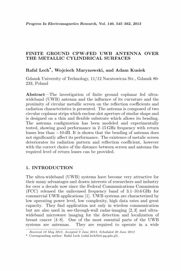
The investigated configurations of the antenna are schematicallydepicted in Figure 2. The curvature of the antenna with radiusr around both orthogonal axes is investigated and the existence ofmetallic cylinder of radius rg is assumed (the distance between cylinderand antenna is d = r − rg).
548 Lech, Marynowski, and Kusiek
Figure 2. Configurations of the analyzed antenna.
3. SIMULATION RESULTS
In this section the results of antenna simulation are presented. Firstthe influence of antenna curvature and the existence of metallicscreen on the antenna reflection parameters are considered. Next theradiation patterns of chosen antenna configuration are calculated andpresented. The simulations were performed with the use of commercialelectromagnetic software.
3.1. Reflection Parameters
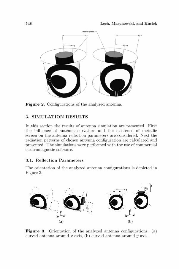
The orientation of the analyzed antenna configurations is depicted inFigure 3.
(a) (b)
Figure 3. Orientation of the analyzed antenna configurations: (a)curved antenna around x axis, (b) curved antenna around y axis.

Progress In Electromagnetics Research, Vol. 140, 2013 549
For the designed antenna in its planar version the reflectioncoefficient obtained from the simulation is better than −13 dB inthe frequency range from 1.9 GHz to 12GHz. The influence of thecurvature of the antenna on its reflection coefficient is analyzed.Figure 4 presents the characteristics of reflection coefficients for theantenna curved around x and y axes (see Figure 3) without metalliccylinder, whereas, Figure 5 illustrates the reflection characteristics forthe curved antenna with the metallic cylinder. As can be observedfrom the obtained results, the curvature of the antenna, especiallyaround the x axis, only slightly affects its performance. The existenceof metallic cylinder deteriorates the reflection characteristics; however,
2 4 6 8 10 12-40
-35
-30
-25
-20
-15
-10
-5
0
Frequency (GHz)
Ma
gn
itu
de
S (
dB
)
planar case
r = 100 mm
r = 70 mm
r = 50 mm
r = 30 mm
2 4 6 8 10 12
Frequency (GHz)
-40
-35
-30
-25
-20
-15
-10
-5
0M
ag
nitu
de
S (
dB
)planar case
r = 100 mm
r = 70 mm
r = 50 mm
r = 30 mm
(a) (b)
Figure 4. Magnitude of reflection coefficient for UWB antennawithout metallic cylinder curved around (a) x axis and (b) y axis.
2 4 6 8 10 12-40
-35
-30
-25
-20
-15
-10
-5
0
Frequency (GHz)
Magnitude S
(dB
)
r = 30 mm, r = 10 mm
r = 50 mm, r = 20 mm
r = 70 mm, r = 40 mm
r = 100 mm, r = 70 mm
(a) (b)
-40
-35
-30
-25
-20
-15
-10
-5
0
Magnitude S
(dB
)
2 4 6 8 10 12
Frequency (GHz)
g
g
g
g
r = 30 mm, r = 10 mm
r = 50 mm, r = 20 mm
r = 70 mm, r = 40 mm
r = 100 mm, r = 70 mm
g
g
g
g
Figure 5. Magnitude of reflection coefficient for UWB antenna withmetallic cylinder curved around (a) x axis and (b) y axis.
550 Lech, Marynowski, and Kusiek
it is possible to select a proper distance between the antenna and themetallic screen to keep the reflection coefficient value bellow −10 dB inthe desired frequency range. The investigations show that this distanceshould not be smaller than 20 mm.
3.2. Radiation Patterns
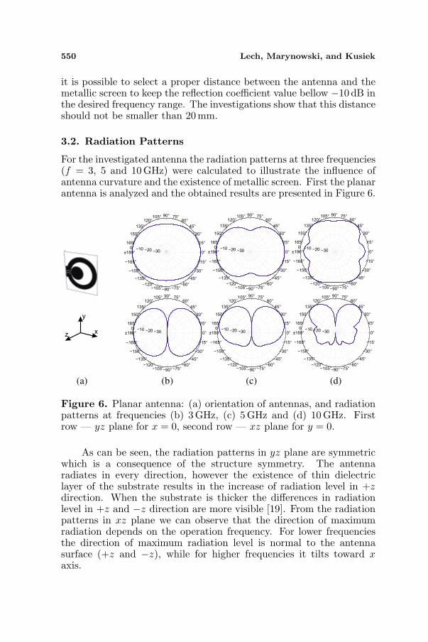
For the investigated antenna the radiation patterns at three frequencies(f = 3, 5 and 10 GHz) were calculated to illustrate the influence ofantenna curvature and the existence of metallic screen. First the planarantenna is analyzed and the obtained results are presented in Figure 6.
(a) (b) (c) (d)
Figure 6. Planar antenna: (a) orientation of antennas, and radiationpatterns at frequencies (b) 3 GHz, (c) 5GHz and (d) 10 GHz. Firstrow — yz plane for x = 0, second row — xz plane for y = 0.
As can be seen, the radiation patterns in yz plane are symmetricwhich is a consequence of the structure symmetry. The antennaradiates in every direction, however the existence of thin dielectriclayer of the substrate results in the increase of radiation level in +zdirection. When the substrate is thicker the differences in radiationlevel in +z and −z direction are more visible [19]. From the radiationpatterns in xz plane we can observe that the direction of maximumradiation depends on the operation frequency. For lower frequenciesthe direction of maximum radiation level is normal to the antennasurface (+z and −z), while for higher frequencies it tilts toward xaxis.

Progress In Electromagnetics Research, Vol. 140, 2013 551
Next, the investigation of curved antenna with and without theexistence of metallic cylinder is conducted. Figures 7 and 8 presentthe calculated radiation patterns for the antennas curved around x
zx
yr
r
rg
30°
45°
60°
0°
15°
30°
45°
60°75°90°105°
120°
135°
150°
165°
±180°
-165°
-150°
-135°
-120°-105° -90° -75°
-60°
-45°
-30°
-15°
-30-20-100
0°
15°
30°
45°
60°75°90°105°
120°
135°
150°
165°
±180°
-165°
-150°
-135°
-120°-105° -90° -75°
-60°
-45°
-30°
-15°
-30-20-100
0°
15°
30°
45°
60°75°90°105°
120°
135°
150°
165°
±180°
-165°
-150°
-135°
-120°-105° -90° -75°
-60°
-45°
-30°
1-5°
-30-20-100
0°
15°
30°
45°
60°75°90°105°
120°
135°
150°
165°
±180°
-165°
-150°
-135°
-120°
-105° -90° -75°-60°
-45°
-30°
-15°
-30-20-100
0°
15°
30°
45°
60°75°90°105°
120°
135°
150°
165°
±180°
-165°
-150°
-135°
-120°-105° -90° -75°
-60°
-45°
-30°
-15°
-30-20-100
0°
15°
30°
45°
60°75°90°105°
120°
135°
150°
165°
±180°
-165°
-150°
-135°
-120°-105° -90° -75°
-60°
-45°
-30°
-15°
-30-20-100
(a) (b) (c) (d)
r = 100 mm
r = 70 mm
r = 50 mm
r = 30 mm
r = 30 mm, r = 10 mm
r = 50 mm, r = 20 mm
r = 70 mm, r = 40 mm
r = 100 mm, r = 70 mm
g
g
g
g
Figure 7. Curved antenna: (a) orientation of antennas, and radiationpatterns at frequencies (b) 3 GHz, (c) 5GHz and (d) 10 GHz. Firstrow — yz plane for x = 0, second row — xz plane for y = 0.
0°
15°
30°
45°
60°75°90°105°
120°
135°
150°
165°
±180°
-165°
-150°
-135°
-120°-105° -90° -75°
-60°
-45°
-30°
-15°
-30-20-100
0°
15°
30°
45°
60°75°90°105°
120°
135°
150°
165°
±180°
165°
-150°
-135°
-120°-105° -90° -75°
-60°
-45°
-30°
-15°
-30-20-100
0°
15°
30°
45°
60°75°90°105°
120°
135°
150°
165°
±180°
-165°
-150°
-135°
-120°-105° -90° -75°
-60°
-45°
-30°
-15°
-30-20-100
0°
15°
30°
45°
60°75°90°105°
120°
135°
150°
165°
±180°
-165°
-150°
-135°
-120°-105° -90° -75°
-60°
-45°
-30°
-15°
-30-20-100
0°
15°
30°
45°
60°75°90°105°
120°
135°
150°
165°
±180°
-165°
-150°
-135°
-120°-105° -90° -75°
-60°
-45°
-30°
-15°
-30-20-100
0°
15°
30°
45°
60°75°90°105°
120°
135°
150°
165°
±180°
-165°
-150°
-135°
-120°-105° -90° -75°
-60°
-45°
-30°
-15°
-30-20-100
30°
60°
z x
y
r
r
rg
(a) (b) (c) (d)
r = 100 mm
r = 70 mm
r = 50 mm
r = 30 mm
r = 30 mm, r = 10 mm
r = 50 mm, r = 20 mm
r = 70 mm, r = 40 mm
r = 100 mm, r = 70 mm
g
g
g
g
Figure 8. Curved antenna: (a) orientation of antennas, and radiationpatterns at frequencies (b) 3 GHz, (c) 5GHz and (d) 10 GHz. Firstrow — yz plane for x = 0, second row — xz plane for y = 0.

552 Lech, Marynowski, and Kusiek
axis and y axis, respectively. The curvature radii for the analyzedantenna are from r = 100 mm to r = 30 mm. When the antenna isplaced on the metallic cylinder the assumed distances are d = 30 mmor d = 20 mm.
As can be observed in the case of antenna without metallic cylinderthe curvature of the antenna around x axis only slightly affects theradiation pattern. In the case of antenna curved around y axis theinfluence is more visible. The 3D radiation characteristics for theconsidered cases are illustrated in the Appendix.
The existence of metallic cylinder deteriorates the antennapatterns. At a fixed value of distance between the screen andantenna the distance in terms of wavelength varies in the antennawide frequency operation range. Therefore, the antenna patterndeterioration are more visible at higher frequencies. Because themetallic cylinder does not cover entire space behind the antenna, as itwould be in the case of planar antenna placed in front of planar metallicscreen, the radiation in −z direction occurs in this case. The selectionof the distance value allows to shape the antenna pattern. Therefore,the correct choice of the distance value should be made depending onthe application and the required shape of radiation characteristic.
4. EXPERIMENTAL RESULTS
The prototype of the investigated antenna was manufactured andmeasured to verify the results obtained from simulations. Thereflection parameters were measured using Agilent PNA-X N5242AVNA Network Analyzer, and the radiation patterns were measured inanechoic chamber using Agilent E5071C ENA Network Analyzer withGeoZondas UWB AU-3.1G10.6G-1 antenna for measurements at 3 GHzand 5GHz, and waveguide horn antenna EMCO model No. 3160-07 for measurements at 10 GHz. Figure 9 presents the photos ofmanufactured antenna, the antenna placed on the tower in anechoic
Figure 9. Photographs of the fabricated antenna and antenna placedon a tower in anechoic chamber.

Progress In Electromagnetics Research, Vol. 140, 2013 553
chamber during measurements and the antenna placed on metalliccylinder. The correct distance between the antenna and metalliccylinder was assured by a holder made form Rohacell material (whichpermittivity is close to 1) which was cut with the use of circuit boardplotter.
4.1. Reflection Parameters
The measurement results, compared with the simulations, of the planarantenna configuration are presented in Figure 10.
The reflection coefficient of the manufactured antenna is lower
Figure 10. Magnitude of reflection coefficient for planar UWBantenna. Solid line — simulations, dashed line — measurements.
0 5 10 15 0 5 10 15-40
-35
-30
-25
-20
-15
-10
-5
0
Frequency (GHz)
Ma
gn
itu
de
S (
dB
)
r = 100 mm
r = 50 mm
r = 30
(a) (b)
r = 100 mm
r = 50 mm
r = 30
-40
-35
-30
-25
-20
-15
-10
-5
0
Ma
gn
itu
de
S (
dB
)
Frequency (GHz)
Figure 11. Magnitude of reflection coefficient for curved UWBantenna: (a) antenna curvature around x axis, (b) antenna curvaturearound y axis. Solid line — simulations, dashed line — measurement.

554 Lech, Marynowski, and Kusiek
than −10 dB from f = 2 GHz, however in the lower frequency rangeform 2 GHz to 4 GHz the measured values are about 2 dB higher thanthe simulated ones. This discrepancies may be due to the effect ofSMA connector.
The measurements of the curved antenna were performed next.The antenna was curved around x and y axis with curvature radiir = 100 mm, 50mm and 30mm. The obtained results are presented inFigure 11.
curvature x-axis
curvature y-axis
0 5 10 15-40
-35
-30
-25
-20
-15
-10
-5
0
Frequency (GHz)
Magnitude S
(dB
)
Figure 12. Magnitude of reflection coefficient for curved UWBantenna over cylindrical metallic cylinder. Antenna curvature radiusr = 70 mm, metallic cylinder radius rg = 38 mm. Solid line —simulations, dashed line — measurement.
As can be seen, besides the case of antenna curved around y axiswith curvature radius r = 30 mm, the antenna reflection coefficientsare below −10 dB in the frequency range from 2GHz to 15 GHz.
In the last example we placed the curved antenna with curvatureradius r = 70mm in front of metallic cylinder with radius rg = 38 mm.The antenna reflection coefficients for the cases of curvature aroundx and y axes are illustrated in Figure 12. Because the manufacturedantenna has the reflection coefficient 2 dB higher in the frequency range3–4GHz than the simulated values, in the case of curved antennaplaced on the metallic cylinder this effect is also visible.
4.2. Radiation Patterns
The measurements of the antenna radiation patterns were performedfor three configurations of the analyzed antenna: planar antenna,curved antenna around x-axis with curvature radius r = 70 mm placedon the metallic cylinder with radius rg = 38 mm and curved antennaaround y-axis with the same curvature radius and cylinder radius.
Progress In Electromagnetics Research, Vol. 140, 2013 555
0°
15°
30°
45°
60°75°90°105°
120°
135°
150°
165°
±180°
-165°
-150°
-135°
-120°-105° -90° -75°
-60°
-45°
-30°
-15°
-30-20-100
0°
15°
30°
45°
60°75°90°105°
120°
135°
150°
165°
±180°
-165°
-150°
-135°
-120°-105° -90° -75°
-60°
-45°
-30°
-15°
-30-20-100
0°
15°
30°
45°
60°75°90°105°
120°
135°
150°
165°
±180°
-165°
-150°
-135°
-120°-105°-90° -75°
-60°
-45°
-30°
-15°
-30-20-100
simulation
measurement
0°
15°
30°
45°
60°75°90°105°
120°
135°
150°
165°
±180°
-165°
-150°
-135°
-120°-105° -90° -75°
-60°
-45°
-30°
15°
-30-20-100
0°
15°
30°
45°
60°75°90°105°
120°
135°
150°
165°
±180°
-165°
-150°
-135°
-120°-105° -90° -75°
-60°
-45°
-30°
-15°
-30-20-100
0°
15°
30°
45°
60°75°90°105°
120°
135°
150°
165°
±180°
-165°
-150°
-135°
-120°-105° -90° -75°
-60°
-45°
-30°
-15°
-30-20-100z x
y
(a) (b) (c) (d)
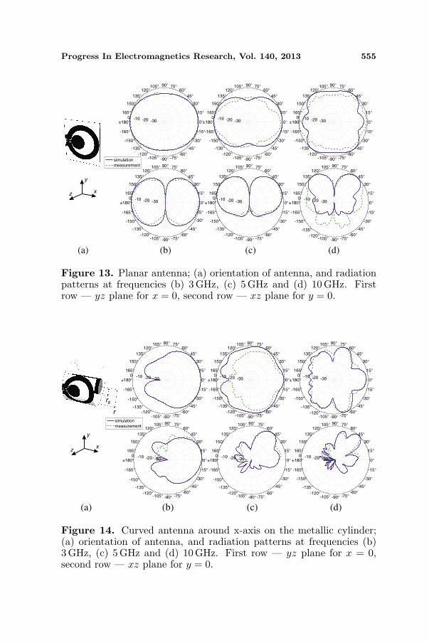
Figure 13. Planar antenna; (a) orientation of antenna, and radiationpatterns at frequencies (b) 3 GHz, (c) 5GHz and (d) 10 GHz. Firstrow — yz plane for x = 0, second row — xz plane for y = 0.
0°
15°
30°
45°
60°75°90°105°
120°
135°
150°
165°
±180°
-165°
-150°
-135°
-120°-105° -90° -75°
-60°
-45°
-30°
-15°
-30-20-100
0°
15°
30°
45°
60°75°90°105°
120°
135°
150°
165°
±180°
-165°
-150°
-135°
-120°-105° -90° -75°
-60°
-45°
-30°
-15°
-30-20-100
0°
15°
30°
45°
60°75°90°105°
120°
135°
150°
165°
±180°
-165°
-150°
-135°
-120°-105° -90° -75°
-60°
-45°
-30°
-15°
-30-20-100
0°
15°
30°
45°
60°75°90°105°
120°
135°
150°
165°
±180°
-165°
-150°
-135°
-120°
-105° -90° -75°-60°
-45°
-30°
-15°
-30-20-100
0°
15°
30°
45°
60°75°90°105°
120°
135°
150°
165°
±180°
-165°
-150°
-135°
-120°-105° -90° -75°
-60°
-45°
-30°
-15°
-30-20-100
0°
15°
30°
45°
60°75°90°105°
120°
135°
150°
165°
±180°
-165°
-150°
-135°
-120°-105° -90° -75°
-60°
-45°
-30°
-15°
-30-20-100
zx
y
r
rg
simulation
measurement
(a) (b) (c) (d)
Figure 14. Curved antenna around x-axis on the metallic cylinder;(a) orientation of antenna, and radiation patterns at frequencies (b)3GHz, (c) 5GHz and (d) 10 GHz. First row — yz plane for x = 0,second row — xz plane for y = 0.

556 Lech, Marynowski, and Kusiek
0°
15°
30°
45°
60°75°90°105°
120°
135°
150°
165°
±180°
-165°
-150°
-135°
-120°-105°-90° -75°
-60°
-45°
-30°
-15°
-30-20-100
0°
15°
30°
45°
60°75°90°105°
120°
135°
150°
165°
±180°
-165°
-150°
-135°
-120°-105° -90° -75°
-60°
-45°
-30°
-15°
-30-20-100
0°
15°
30°
45°
60°75°90°105°
120°
135°
150°
165°
±180°
-165°
-150°
-135°
-120°-105°-90° -75°
-60°
-45°
-30°
-15°
-30-20-100
0°
15°
30°
45°
60°75°90°105°
120°
135°
150°
165°
±180°
-165°
-150°
-135°
-120°-105° -90° -75°
-60°
-45°
-30°
-15°
-30-20-100
0°
15°
30°
45°
60°75°90°105°
120°
135°
150°
165°
±180°
-165°
-150°
-135°
-120°-105° -90° -75°
-60°
-45°
-30°
-15°
-30-20-100
0°
15°
30°
45°
60°75°90°105°
120°
135°
150°
165°
±180°
-165°
-150°
-135°
-120°-105°-90° -75°
-60°
-45°
-30°
-15°
-30-20-100
rg
r
z x
y
simulation
measurement
(a) (b) (c) (d)
Figure 15. Curved antenna around y-axis on the metallic cylinder;(a) orientation of antenna, and radiation patterns at frequencies (b)3GHz, (c) 5GHz and (d) 10 GHz. First row — yz plane for x = 0,second row — xz plane for y = 0.
All measurements were performed at frequencies 3 GHz, 5 GHzand 10 GHz. The results for planar antenna are presented in Figure 13,while for the curved cases are illustrated in Figures 14 and 15.Although, there are some discrepancies between the measured andsimulated results the character of the patterns are similar and theobtained agreement is satisfactory.
5. CONCLUSION
The investigation of finite ground CPW-fed UWB antenna and theinfluence of its curvature and the proximity of circular metallicscreen on the reflection coefficients and radiation characteristicswas presented. The investigated antenna was designed on a thinand flexible substrate which allowed its bending. The antennaconfiguration has been modeled and experimentally tested, showinggood performance in 2–15GHz frequency with return losses lessthan −10 dB. The antenna bending does not significantly affect itsperformance and therefore is suitable for the use in flexible electronicsystems. The performed investigations allow us to formulate some rulesconcerning the antenna design for the curved surface application. Inorder to apply the antenna on curved surfaces or in the proximity

Progress In Electromagnetics Research, Vol. 140, 2013 557
of metallic screen the base antenna structure (its planar version)should be well matched (the reflection coefficient should be lower than−13 dB in the entire frequency range) as its bending may deteriorateits performance. The distance of metallic screen should be greater than20mm in order to keep the reflection coefficient in the acceptable levelin the entire frequency range. As the distance between metallic screenand the antenna affects the shape of its radiation patterns, especiallyat higher frequencies, the correct choice of the distance value shouldbe made depending on the application.
APPENDIX A. 3D RADIATION PATTERNS
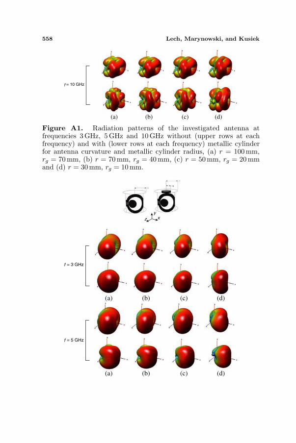
The 3D radiation patterns of antenna analyzed in Chapter 3 arepresented here. Figures A1 and A2 present the results for curvedantennas with and without the metallic screen as described inChapter 3.
f = 3 GHz
z xy
f = 5 GHz
(a) (b) (c) (d)
(a) (b) (c) (d)
558 Lech, Marynowski, and Kusiek
f = 10 GHz
(a) (b) (c) (d)
Figure A1. Radiation patterns of the investigated antenna atfrequencies 3 GHz, 5 GHz and 10 GHz without (upper rows at eachfrequency) and with (lower rows at each frequency) metallic cylinderfor antenna curvature and metallic cylinder radius, (a) r = 100 mm,rg = 70 mm, (b) r = 70 mm, rg = 40mm, (c) r = 50mm, rg = 20 mmand (d) r = 30 mm, rg = 10 mm.
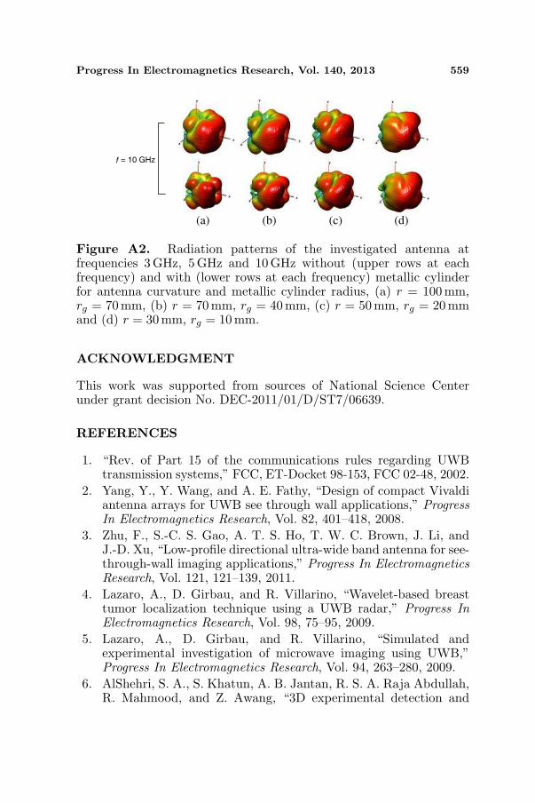
f = 3 GHz
z xy
f = 5 GHz
(a) (b) (c) (d)
(a) (b) (c) (d)
Progress In Electromagnetics Research, Vol. 140, 2013 559
f = 10 GHz
(a) (b) (c) (d)
Figure A2. Radiation patterns of the investigated antenna atfrequencies 3 GHz, 5 GHz and 10 GHz without (upper rows at eachfrequency) and with (lower rows at each frequency) metallic cylinderfor antenna curvature and metallic cylinder radius, (a) r = 100 mm,rg = 70 mm, (b) r = 70 mm, rg = 40mm, (c) r = 50mm, rg = 20 mmand (d) r = 30 mm, rg = 10 mm.
ACKNOWLEDGMENT
This work was supported from sources of National Science Centerunder grant decision No. DEC-2011/01/D/ST7/06639.
REFERENCES
1. “Rev. of Part 15 of the communications rules regarding UWBtransmission systems,” FCC, ET-Docket 98-153, FCC 02-48, 2002.
2. Yang, Y., Y. Wang, and A. E. Fathy, “Design of compact Vivaldiantenna arrays for UWB see through wall applications,” ProgressIn Electromagnetics Research, Vol. 82, 401–418, 2008.
3. Zhu, F., S.-C. S. Gao, A. T. S. Ho, T. W. C. Brown, J. Li, andJ.-D. Xu, “Low-profile directional ultra-wide band antenna for see-through-wall imaging applications,” Progress In ElectromagneticsResearch, Vol. 121, 121–139, 2011.
4. Lazaro, A., D. Girbau, and R. Villarino, “Wavelet-based breasttumor localization technique using a UWB radar,” Progress InElectromagnetics Research, Vol. 98, 75–95, 2009.
5. Lazaro, A., D. Girbau, and R. Villarino, “Simulated andexperimental investigation of microwave imaging using UWB,”Progress In Electromagnetics Research, Vol. 94, 263–280, 2009.
6. AlShehri, S. A., S. Khatun, A. B. Jantan, R. S. A. Raja Abdullah,R. Mahmood, and Z. Awang, “3D experimental detection and

560 Lech, Marynowski, and Kusiek
discrimination of malignant and benign breast tumor usingNN-based UWB imaging system,” Progress In ElectromagneticsResearch, Vol. 116, 221–237, 2011.
7. Conceicao, R. C., M. O’Halloran, M. Glavin, and E. Jones,“Numerical modelling for ultra wideband radar breast cancerdetection and classification,” Progress In ElectromagneticsResearch B, Vol. 34, 145–171, 2011.
8. AlShehri, S. A., S. Khatun, A. B. Jantan, R. S. A. Raja Abdul-lah, R. Mahmood, and Z. Awang, “Experimental breast tumordetection using NN-based UWB imaging,” Progress In Electro-magnetics Research, Vol. 111, 447–465, 2011.
9. Chen, D. and C.-H. Cheng, “A novel compact ultra-wideband(UWB) wide slot antenna with via holes,” Progress InElectromagnetics Research, Vol. 94, 343–349, 2009.
10. Xu, H.-Y., H. Zhang, K. Lu, and X.-F. Zeng, “A holly-leaf-shapedmonopole antenna with low RCS for UWB application,” ProgressIn Electromagnetics Research, Vol. 117, 35–50, 2011.
11. Zivkovic, I. and K. Scheffler, “A new inovative antenna conceptfor both narrow band and UWB applications,” Progress InElectromagnetics Research, Vol. 139, 121–131, 2013.
12. Reddy, G. S., S. K. Mishra, S. Kharche, and J. Mukherjee, “Highgain and low cross-polar compact printed elliptical monopoleUWB antenna loaded with partial ground and parasitic patches,”Progress In Electromagnetics Research B, Vol. 43, 151–167, 2012.
13. Zhang, Z. and Y. H. Lee, “A robust CAD tool for integrated designof UWB antenna system,” Progress In Electromagnetics Research,Vol. 112, 441–457, 2011.
14. Liao, Z.-L., F.-S. Zhang, G. Xie, W. Zhai, and L.-N. Chen,“An omnidirectional and band-notched ultra wide band antennaon double substrates crossing,” Progress In ElectromagneticsResearch C, Vol. 22, 231–240, 2011.
15. Sadat, S., M. Fardis, F. G. Geran, and G. R. Dadashzadeh,“A compact microstrip square-ring slot antenna for UWBapplications,” Progress In Electromagnetics Research, Vol. 67,173–179, 2007.
16. Gong, B., J. L. Li, Q.-R. Zheng, Y.-Z. Yin, and X.-S. Ren, “Acompact inductively loaded monopole antenna for future UWBapplications,” Progress In Electromagnetics Research, Vol. 139,265–275, 2013.
17. Osman, M. A. R., M. K. A. Rahim, N. A. Samsuri, H. A. M. Salim,and M. F. Ali, “Embroidered fully textile wearable antenna for

Progress In Electromagnetics Research, Vol. 140, 2013 561
medical monitoring applications,” Progress In ElectromagneticsResearch, Vol. 117, 321–337, 2011.
18. Chen, M. and J. Wang, “Compact CPW-fed circular slotantenna for ultra-wideband applications,” 2008. 8th InternationalSymposium Antennas, Propagation and EM Theory, 78–81,Nov. 25, 2008.
19. Marynowski, W. and J. Mazur, “Design of UWB coplanar antennawith reduced ground plane,” Journal of Electromagnetic Wavesand Applications, Vol. 23, No. 13, 1707–1713, 2009.
20. Pouyanfar, N. and S. Ahdi Rezaeieh, “Compact UWB antennawith inverted hat shaped resonator and shortening via pinsfor filtering properties,” Progress In Electromagnetics ResearchLetters, Vol. 33, 187–196, 2012.
21. Zhang, S.-M., F.-S. Zhang, W.-Z. Li, T. Quan, and H.-Y. Wu,“A compact UWB monopole antenna with WiMAX and WLANband rejections,” Progress In Electromagnetics Research Letters,Vol. 31, 159–168, 2012.
22. Li, W.-M., T. Ni, T. Quan, and Y.-C. Jiao, “A compact CPW-FED UWB antenna with WiMAX-band notched characteristics,”Progress In Electromagnetics Research Letters, Vol. 26, 79–85,2011.
23. Levy, M., S. Bose, A. V. Dinh, and D. Sriram Kumar, “A novelisticfractal antenna for ultra wideband (UWB) applications,” ProgressIn Electromagnetics Research B, Vol. 45, 369–393, 2012.
24. Tilanthe, P., P. C. Sharma, and T. K. Bandopadhyay, “Acompact UWB antenna with dual band rejection,” Progress InElectromagnetics Research B, Vol. 35, 389–405, 2011.
25. Lech, R., W. Marynowski, and A. Kusiek, “UWB microstripantennas on a cylindrical surfaces,” Progress In ElectromagneticsResearch Symposium Abstracts, 496, Taipei, Taiwan, March 25–28, 2013.
26. Hu, J., “Overview of flexible electronics from ITRIs viewpoint,”28th VLSI Test Symposium (VTS), 84, Apr. 19–22, 2010.
27. Nathan, A. and B. R. Chalamala, “Special issue on flexibleelectronics technology, Part 1: Systems and applications,”Proceedings of the IEEE, Vol. 93, No. 7, 1235–1238, Jul. 2005.
28. Josefsson, L. and P. Persson, “Conformal array synthesis includingmutual-coupling,” Electronic Letters, Vol. 35, No. 8, 625–627,Apr. 1999.
29. Xu, Z., H. Li, Q.-Z. Liu, and J.-Y. Li, “Pattern synthesisof conformal antenna array by the hybrid genetic algorithm,”

562 Lech, Marynowski, and Kusiek
Progress In Electromagnetics Research, Vol. 79, 75–90, 2008.30. Si, W., L. Wan, L. Liu, and Z. Tian, “Fast estimation of frequency
and 2-d DOAs for cylindrical conformal array antenna using state-space and propagator method,” Progress In ElectromagneticsResearch, Vol. 137, 51–71, 2013.
31. Denidni, T. A. and M. A. Habib, “Broadband printed CPW-fedcircular slot antenna,” Electronics Letters, Vol. 42, No. 3, 135–136,Feb. 2, 2006.