finite control volume analysis cee 331 june 28, 2015 cee 331 june 28, 2015 application of reynolds...
Post on 21-Dec-2015
218 views
TRANSCRIPT
Finite Control Volume AnalysisFinite Control Volume Analysis
CEE 331
April 18, 2023
CEE 331
April 18, 2023
Application of Reynolds Transport Theorem

Moving from a System to a Control Volume
Moving from a System to a Control Volume
MassLinear MomentumMoment of MomentumEnergyPutting it all together!
MassLinear MomentumMoment of MomentumEnergyPutting it all together!

Conservation of MassConservation of Mass
B = Total amount of ____ in the systemB = Total amount of ____ in the systemb = ____ per unit mass = __ b = ____ per unit mass = __ B = Total amount of ____ in the systemB = Total amount of ____ in the systemb = ____ per unit mass = __ b = ____ per unit mass = __
ˆsys
cv cs
DMdV dA
Dt tr r
¶= + ׶ ò ò V n̂sys
cv cs
DMdV dA
Dt tr r
¶= + ׶ ò ò V n
ˆcs cv
dA dVt
r r
× =-¶ò òV n̂
cs cv
dA dVt
r r
× =-¶ò òV n
massmass11massmass
But DMsys/Dt = 0!But DMsys/Dt = 0!
cv equationcv equation
mass leaving - mass entering = - rate of increase of mass in cvmass leaving - mass entering = - rate of increase of mass in cv
ˆsys
cv cs
DBbdV b dA
Dt tr r
¶= + ׶ ò ò V n̂sys
cv cs
DBbdV b dA
Dt tr r
¶= + ׶ ò ò V n
Continuity Equation
Conservation of MassConservation of Mass
1 2
1 1 1 2 2 2ˆ ˆ 0cs cs
dA dAr r× + × =ò òV n V n1 2
1 1 1 2 2 2ˆ ˆ 0cs cs
dA dAr r× + × =ò òV n V n
1122
VV11AA11
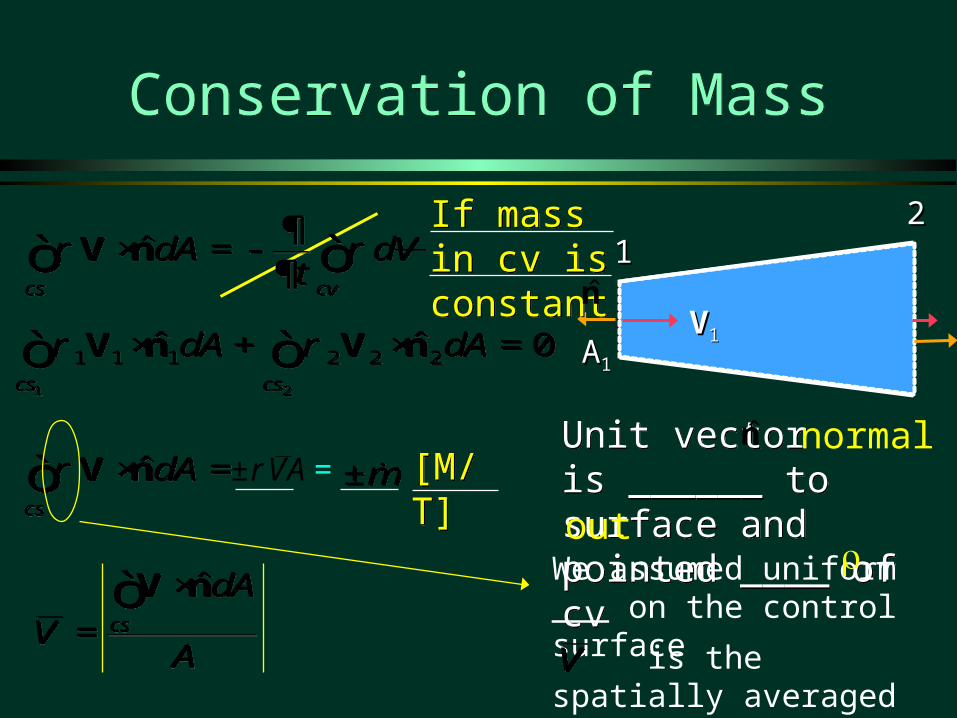
If mass in cv is constantIf mass in cv is constant
Unit vector is ______ to surface and pointed ____ of cv
Unit vector is ______ to surface and pointed ____ of cv
ˆcs cv
dA dVt
r r
× =-¶ò òV n̂
cs cv
dA dVt
r r
× =-¶ò òV n
n̂ normal
out
ˆcs
dAr × =ò V n̂cs
dAr × =ò V n m±m±
ˆcs
dA
VA
×
=òV n̂cs
dA
VA
×
=òV n
VAr± =
n̂
We assumed uniform ___ on the control surface
is the spatially averaged velocity normal to the csVV
[M/T][M/T]

Continuity Equation for Constant Density and Uniform Velocity
Continuity Equation for Constant Density and Uniform Velocity
1 21 1 2 2 0V A V Ar r- + =1 21 1 2 2 0V A V Ar r- + =
1 21 2V A V A Q= =1 21 2V A V A Q= =
1 2
1 1 1 2 2 2ˆ ˆ 0cs cs
dA dAr r× + × =ò òV n V n1 2
1 1 1 2 2 2ˆ ˆ 0cs cs
dA dAr r× + × =ò òV n V n
Density is constant across cs
Density is the same at cs1 and cs2[L3/T][L3/T]
Simple version of the continuity equation for conditions of constant density. It is understood that the velocities are either ________ or _______ ________.
1 1 2 2V A V A Q= =1 1 2 2V A V A Q= =
uniform spatially averaged

Example: Conservation of Mass?Example: Conservation of Mass?
The flow out of a reservoir is 2 L/s. The flow out of a reservoir is 2 L/s. The reservoir surface is 5 m x 5 m. The reservoir surface is 5 m x 5 m. How fast is the reservoir surface How fast is the reservoir surface dropping?dropping?
resAQ
dtdh
resAQ
dtdh
hh
dt
dhAQ res
out dt
dhAQ res
out ExampleExample
Constant densityConstant density
ˆcs cv
dA dVt
r r
× =-¶ò òV n̂
cs cv
dA dVt
r r
× =-¶ò òV n
ˆcs
VdA
t
× =-¶òV n̂
cs
VdA
t
× =-¶òV n
out in
dVQ Q
dt- =-out in
dVQ Q
dt- =- Velocity of the reservoir surface

Linear Momentum EquationLinear Momentum Equation
m=B Vm=B Vmm
=V
bmm
=V
b
cv equationcv equation
momentummomentum momentum/unit massmomentum/unit mass
Steady stateSteady state
ˆsys
cv cs
DBbdV b dA
Dt tr r
¶= + ׶ ò ò V n̂sys
cv cs
DBbdV b dA
Dt tr r
¶= + ׶ ò ò V n
ˆcv cs
DmdV dA
Dt tr r
¶= + ׶ ò ò
VV V V n̂
cv cs
DmdV dA
Dt tr r
¶= + ׶ ò ò
VV V V n
ˆcs
DmdA
Dtr= ×ò
VV V n̂
cs
DmdA
Dtr= ×ò
VV V n
0F ¹å 0F ¹å
This is the “ma” side of the F = ma equation!

Linear Momentum EquationLinear Momentum Equation
( ) ( )1 1 1 1 2 2 2 2
DmV A V A
Dtr r=- +
VV V( ) ( )1 1 1 1 2 2 2 2
DmV A V A
Dtr r=- +
VV V
111111 VVM QAV 111111 VVM QAV
222222 VVM QAV 222222 VVM QAV
AssumptionsAssumptionsAssumptionsAssumptions
Vectors!!!Vectors!!!
Uniform densityUniform densityUniform velocityUniform velocity
V AV ASteadySteady
ˆcs
DmdA
Dtr= ×ò
VV V n̂
cs
DmdA
Dtr= ×ò
VV V n
1 2
1 1 1 1 2 2 2 2ˆ ˆcs cs
DmdA dA
Dtr r= × + ×ò ò
VV V n V V n
1 2
1 1 1 1 2 2 2 2ˆ ˆcs cs
DmdA dA
Dtr r= × + ×ò ò
VV V n V V n
V fluid velocity relative to cv
V fluid velocity relative to cv

( )1 2
D m
Dt= = +å
VF M M
( )1 2
D m
Dt= = +å
VF M M
Steady Control Volume Form of Newton’s Second Law
Steady Control Volume Form of Newton’s Second Law
What are the forces acting on the fluid in the control volume?
What are the forces acting on the fluid in the control volume?
21 MMF 21 MMF
1 2 wall wallp p p t= + + + +å F F F F FW1 2 wall wallp p p t= + + + +å F F F F FW
GravityGravityShear forces at the wallsShear forces at the wallsPressure forces at the wallsPressure forces at the wallsPressure forces on the endsPressure forces on the ends
Why no shear on control surfaces? _______________________________No velocity gradient normal to surface

Resultant Force on the Solid Surfaces
Resultant Force on the Solid Surfaces
The shear forces on the walls and the pressure forces on the walls are generally the unknowns
Often the problem is to calculate the total force exerted by the fluid on the solid surfaces
The magnitude and direction of the force determines size of _____________needed to keep pipe in
place force on the vane of a pump or turbine...
1 2p p ss= + + +å F F F FW1 2p p ss= + + +å F F F FW wallwall
FFpss Fwallwall
FFpss F
=force applied by solid surfaces=force applied by solid surfaces
thrust blocksthrust blocks

Linear Momentum EquationLinear Momentum Equation
1 2p p ss= + + +å F F F FW1 2p p ss= + + +å F F F FW
21 MMF 21 MMF 1 21 2 p p ss+ = + + +M M F F FW1 21 2 p p ss+ = + + +M M F F FW
The momentum vectors have the same direction as the velocity vectors
The momentum vectors have the same direction as the velocity vectors
Fp1Fp1
Fp2Fp2
WW
M1M1
M2M2
FssyFssy
FssxFssx
( )1 1Qr=-M V( )1 1Qr=-M V
( )2 2Qr=M V( )2 2Qr=M V
Forces by solid surfaces on fluid

Reducing elbow in vertical plane with water flow Reducing elbow in vertical plane with water flow of 300 L/s. The volume of water in the elbow is 200 of 300 L/s. The volume of water in the elbow is 200 L.L.Energy loss is negligible.Energy loss is negligible.Calculate the force of the elbow on the fluid.Calculate the force of the elbow on the fluid.W = _________W = _________
section 1section 1 section 2section 2DD 50 cm50 cm 30 cm 30 cmAA __________________ __________________VV __________________ __________________p p 150 kPa150 kPa __________________MM __________________ __________________FFpp __________________ __________________
Example: Reducing ElbowExample: Reducing Elbow
1 21 2 p p ss+ = + + +M M F F FW1 21 2 p p ss+ = + + +M M F F FW
1111
22
1 m1 m
z
xDirection of V vectorsDirection of V vectors
0.196 m20.196 m2 0.071 m20.071 m2
1.53 m/s ↑1.53 m/s ↑ 4.23 m/s →4.23 m/s →
-459 N ↑-459 N ↑ 1269 N →1269 N →29,400 N ↑29,400 N ↑
-1961 N ↑-1961 N ↑
??
?←?←

Example: What is p2?Example: What is p2?
2 21 1 2 2
1 21 22 2
p V p Vz z
g gg g+ + = + +
2 21 1 2 2
1 21 22 2
p V p Vz z
g gg g+ + = + +
2 21 2
2 1 1 2 2 2V V
p p z zg g
gé ù
= + - + -ê úë û
2 21 2
2 1 1 2 2 2V V
p p z zg g
gé ù
= + - + -ê úë û
( ) ( ) ( )( )
( )( )
2 23 3
2 2 2
1.53 m/s 4.23 m/s150 x 10 Pa 9810 N/m 0 1 m
2 9.8 m/s 2 9.8 m/sp
é ù= + - + -ê ú
ê úë û( ) ( ) ( )
( )( )( )
2 23 3
2 2 2
1.53 m/s 4.23 m/s150 x 10 Pa 9810 N/m 0 1 m
2 9.8 m/s 2 9.8 m/sp
é ù= + - + -ê ú
ê úë û
P2 = 132 kPaP2 = 132 kPa Fp2 = 9400 NFp2 = 9400 N

Example: Reducing ElbowHorizontal Forces
Example: Reducing ElbowHorizontal Forces
1 21 2 p p ss+ = + + +M M F F FW1 21 2 p p ss+ = + + +M M F F FW
1111
2222
1 21 2ss p p= + - - -F M M F FW1 21 2ss p p= + - - -F M M F FW
xxx pss FMF22
xxx pss FMF22
( ) ( )1269 9400xssF N - N= -( ) ( )1269 9400xssF N - N= -
10.7kNxssF =10.7kNxssF =
Pipe wants to move to the _________leftleft
z
xForce of pipe on fluidForce of pipe on fluid
Fp2Fp2
M2M2
1 21 2x x x x xss x p pF M M F F= + - - -W1 21 2x x x x xss x p pF M M F F= + - - -W
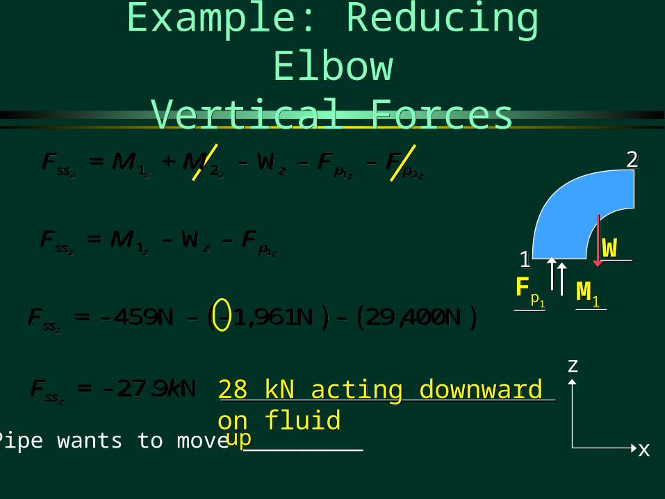
Example: Reducing ElbowVertical Forces
Example: Reducing ElbowVertical Forces
1 21 2z z z z zss z p pF M M F F= + - - -W1 21 2z z z z zss z p pF M M F F= + - - -W
11z z zss z pF M F= - -W11z z zss z pF M F= - -W
( ) ( )459N 1,961N 29,400NzssF =- - - -( ) ( )459N 1,961N 29,400NzssF =- - - -
1111
2222
27.9 NzssF k=- 27.9 NzssF k=-
Pipe wants to move _________upup
z
x
Fp1Fp1
M1M1
WW
28 kN acting downward on fluid28 kN acting downward on fluid

Example: Fire nozzleExample: Fire nozzle
A small fire nozzle is used to create a powerful jet to reach far into a blaze. Estimate the force that the water exerts on the fire nozzle. The pressure at section 1 is 1000 kPa (gage). Ignore frictional losses in the nozzle.
A small fire nozzle is used to create a powerful jet to reach far into a blaze. Estimate the force that the water exerts on the fire nozzle. The pressure at section 1 is 1000 kPa (gage). Ignore frictional losses in the nozzle.
8 cm8 cm 2.5 cm2.5 cm

Example: Momentum with Complex Geometry
Example: Momentum with Complex Geometry
L/s 101 Q L/s 101 Q
cs1cs1
cs3cs3
0yF 0yF
1
2cs2cs2
Find Q2, Q3 and force on the wedge.
xx
yy
3
m/s 201 V m/s 201 V
3 50 2 130
1000 kg / m3
1 10
Unknown: ________________Q2, Q3, V2, V3, FxQ2, Q3, V2, V3, Fx

5 Unknowns: Need 5 Equations5 Unknowns: Need 5 Equations
cs1cs1
cs3cs3
1
cs2cs2
xx
yy
3
Unknowns: Q2, Q3, V2, V3, FxUnknowns: Q2, Q3, V2, V3, Fx
ContinuityContinuity
Bernoulli (2x)Bernoulli (2x)
Momentum (in x and y)Momentum (in x and y)
Q Q Q1 2 3 Q Q Q1 2 3
2
1 2 31 2 3 p p p ss+ + = + + + +M M M F F F FW1 2 31 2 3 p p p ss+ + = + + + +M M M F F F FW
V V1 2
V V1 3
2 21 1 2 2
1 21 22 2
p V p Vz z
g gg g+ + = + +
Identify the 5 equations!

Solve for Q2 and Q3Solve for Q2 and Q3
xx
yy
1 2 31 2 3 p p p ss+ + = + + + +M M M F F F FW1 2 31 2 3 p p p ss+ + = + + + +M M M F F F FW
F M M My y y y 0 1 2 3F M M My y y y 0 1 2 3
0 1 1 1 2 2 2 3 3 3 QV Q V Q Vsin sin sin0 1 1 1 2 2 2 3 3 3 QV Q V Q Vsin sin sin
V sin V sin Component of velocity in y directionComponent of velocity in y direction
Mass conservationMass conservationQ Q Q1 2 3 Q Q Q1 2 3
V V V1 2 3 V V V1 2 3 Negligible losses – apply BernoulliNegligible losses – apply Bernoulli
atmospheric pressureatmospheric pressure

Solve for Q2 and Q3Solve for Q2 and Q3
0 1 1 2 2 3 3 Q Q Qsin sin sin
Q Q2 11 3
2 3
sin sin
sin sin
a fa f
Q Q2 1
10 50
130 50
sin sin
sin sin
af a fa f a f
Q2 6.133 L / s
Q3 3.867 L / s
Why is Q2 greater than Q3?
Q Q Q3 1 2 Q Q Q3 1 2
0 1 1 1 2 2 2 3 3 3 QV Q V Q Vsin sin sin0 1 1 1 2 2 2 3 3 3 QV Q V Q Vsin sin sin

Solve for FxSolve for Fx
F M M Mx x x x 1 2 3F M M Mx x x x 1 2 3
F QV Q V Q Vx 1 1 1 2 1 2 3 1 3cos cos cosF QV Q V Q Vx 1 1 1 2 1 2 3 1 3cos cos cos
F V Q Q Qx 1 1 1 2 2 3 3cos cos cosF V Q Q Qx 1 1 1 2 2 3 3cos cos cos
F Nx 226F Nx 226
Fx
L
N
MMMM
O
Q
PPPP1000 kg / m 20 m / s
0.01 m / s cos 10
0.006133 m / s cos 130
0.003867 m / s cos 50
3
3
3
3
c ha fc hafc ha fc ha f
Fx
L
N
MMMM
O
Q
PPPP1000 kg / m 20 m / s
0.01 m / s cos 10
0.006133 m / s cos 130
0.003867 m / s cos 50
3
3
3
3
c ha fc hafc ha fc ha f
Force of wedge on fluidForce of wedge on fluid

Vector solutionVector solution
200N111 VQM 200N111 VQM
122.66N222 VQM 122.66N222 VQM
77.34N333 VQM 77.34N333 VQM
sLQ /133.62 sLQ /133.62
sLQ /867.33 sLQ /867.33
sLQ /102 sLQ /102
M M M F1 2 3 ss

Vector AdditionVector Addition
cs1
cs3
1
2cs2
x
y
3
1M1M
2M2M3M3M
ssFssF
M M M F1 2 3 ss
Where is the line of action of Fss?

Moment of Momentum EquationMoment of Momentum Equation
m=B r×Vm=B r×V
mm
=r×V
bm
m=
r×Vb
( ) ( )ˆcs
dAr= ×òT r×V V n( ) ( )ˆcs
dAr= ×òT r×V V n
cv equationcv equation
Moment of momentumMoment of momentum
Moment of momentum/unit massMoment of momentum/unit mass
Steady stateSteady state
ˆsys
cv cs
DBbdV b dA
Dt tr r
¶= + ׶ ò ò V n̂sys
cv cs
DBbdV b dA
Dt tr r
¶= + ׶ ò ò V n
( ) ( ) ( )ˆcv cs
D mdV dA
Dt tr r
¶= + ׶ ò ò
r×Vr×V r×V V n
( ) ( ) ( )ˆcv cs
D mdV dA
Dt tr r
¶= + ׶ ò ò
r×Vr×V r×V V n

Application to TurbomachineryApplication to Turbomachinery
( ) ( )z t n
cs
T rV V dAr=ò( ) ( )z t n
cs
T rV V dAr=ò
rr22
rr11
VVnnVVtt
( ) ( )2 12 1z t tT Q r V rVr é ù= -ë û( ) ( )2 12 1z t tT Q r V rVr é ù= -ë û
cs1cs1 cs2cs2
( ) ( )ˆcs
dAr= ×òT r×V V n( ) ( )ˆcs
dAr= ×òT r×V V nrVt Vn

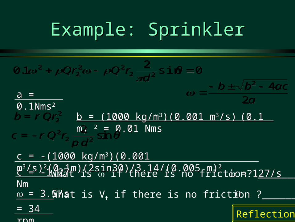
Example: SprinklerExample: Sprinkler
( ) ( )2 12 1z t tT Q r V rVr é ù= -ë û( ) ( )2 12 1z t tT Q r V rVr é ù= -ë û
Total flow is 1 L/s.Total flow is 1 L/s.Jet diameter is 0.5 cm.Jet diameter is 0.5 cm.Friction exerts a torque of Friction exerts a torque of 0.1 N-m-s0.1 N-m-s22 22.. = 30º.= 30º.Find the speed of rotation.Find the speed of rotation.
Total flow is 1 L/s.Total flow is 1 L/s.Jet diameter is 0.5 cm.Jet diameter is 0.5 cm.Friction exerts a torque of Friction exerts a torque of 0.1 N-m-s0.1 N-m-s22 22.. = 30º.= 30º.Find the speed of rotation.Find the speed of rotation.
vvttvvtt
10 cm10 cm10 cm10 cm 2
220.1 tQr Vw r- =
2
220.1 tQr Vw r- =
2 2sinjett
jet
QV θ r
Aw=- +
2 2sinjett
jet
QV θ r
Aw=- +
222
2 sin2/4
1.0 rθdQ
Qr
222
2 sin2/4
1.0 rθdQ
Qr
0sin2
1.0 2222
22 θ
drQQr
0sin
21.0 22
222
2 θd
rQQr
Vt and Vn are defined relative to control surfaces.
cs2cs2
= 34 rpm= 34 rpm
c = -(1000 kg/m3)(0.001 m3/s)2(0.1m)(2sin30)/3.14/(0.005 m)2c = -(1000 kg/m3)(0.001 m3/s)2(0.1m)(2sin30)/3.14/(0.005 m)2
b = (1000 kg/m3)(0.001 m3/s) (0.1 m) 2 = 0.01 Nmsb = (1000 kg/m3)(0.001 m3/s) (0.1 m) 2 = 0.01 Nms
Example: SprinklerExample: Sprinkler
0sin2
1.0 2222
22 θ
drQQr
0sin
21.0 22
222
2 θd
rQQr
aacbb
242
aacbb
242
22b Qrr= 22b Qrr=
22 2
2sinc Q r θ
dr
p=- 2
2 2
2sinc Q r θ
dr
p=-
c = -1.27 Nmc = -1.27 Nm
= 3.5/s= 3.5/s
a = 0.1Nms2a = 0.1Nms2
Reflections
What is if there is no friction? ___________
What is Vt if there is no friction ?__________
= 127/s= 127/s

cv equationcv equation
Energy EquationEnergy Equation
First law of thermodynamics: The heat QFirst law of thermodynamics: The heat QHH added to a system plus added to a system plus
the work W done on the system equals the change in total energy the work W done on the system equals the change in total energy E of the system.E of the system.net net 2 1in in
Q W E E+ = -net net 2 1in in
Q W E E+ = -
net shaftin
ˆcs
DEQ W p dA
Dt= + - ×ò V n
net shaftin
ˆcs
DEQ W p dA
Dt= + - ×ò V n
net pr shaftin
W W W= +net pr shaftin
W W W= +
pr ˆcs
W p dA=- ×ò V npr ˆ
cs
W p dA=- ×ò V n
What is for a system?DE/Dt
ˆsys
cv cs
DBbdV b dA
Dt tr r
¶= + ׶ ò ò V n̂sys
cv cs
DBbdV b dA
Dt tr r
¶= + ׶ ò ò V n
ˆcv cs
DEedV e dA
Dt tr r
¶= + ׶ ò ò V n̂
cv cs
DEedV e dA
Dt tr r
¶= + ׶ ò ò V n
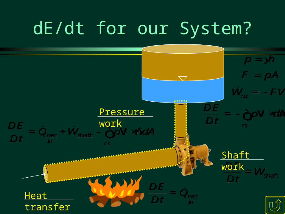
dE/dt for our System?dE/dt for our System?
netin
DEQ
Dt=
netin
DEQ
Dt=
shaft
DEW
Dt=
shaft
DEW
Dt=
cs
DEp d
Dt=- ×ò V A
cs
DEp d
Dt=- ×ò V A
hp hp
pAF pAF
prW FV=-prW FV=-
Heat transferHeat transfer
Shaft workShaft work
Pressure workPressure work
net shaftin
ˆcs
DEQ W p dA
Dt= + - ×ò V n
net shaftin
ˆcs
DEQ W p dA
Dt= + - ×ò V n

General Energy EquationGeneral Energy Equation
net shaftin
ˆ ˆcs cv cs
DEQ W p dA edV e dA
Dt tr r
¶= + - × = + ×
¶ò ò òV n V n net shaftin
ˆ ˆcs cv cs
DEQ W p dA edV e dA
Dt tr r
¶= + - × = + ×
¶ò ò òV n V n
net shaftin
ˆcv cs
pQ W e d e dA
tr r
ræ ö
= + = " + + ×ç ÷è ø¶ ò ò V n net shaftin
ˆcv cs
pQ W e d e dA
tr r
ræ ö
= + = " + + ×ç ÷è ø¶ ò ò V n
2
2V
e gz u= + +2
2V
e gz u= + +zz
cv equationcv equation1st Law of Thermo1st Law of Thermo
PotentialPotential KineticKinetic Internal (molecular spacing and forces)Internal (molecular spacing and forces)
TotalTotal

SteadySteady
Simplify the Energy EquationSimplify the Energy Equation
netin
2
shaft ˆ2
cs
p Vq w m gz u dAr
ræ öæ ö+ = + + + ×ç ÷ ç ÷è ø è øò V n
netin
2
shaft ˆ2
cs
p Vq w m gz u dAr
ræ öæ ö+ = + + + ×ç ÷ ç ÷è ø è øò V n
cgzp
cgzp
2
2V
e gz u= + +2
2V
e gz u= + +
Assume...Assume...Assume...Assume...
But V is often ____________ over control surface!But V is often ____________ over control surface!But V is often ____________ over control surface!But V is often ____________ over control surface!
Hydrostatic pressure distribution at csHydrostatic pressure distribution at cs
ŭ is uniform over csŭ is uniform over cs
not uniformnot uniform
00
net shaftin
ˆcv cs
pQ W e d e dA
tr r
ræ ö
+ = " + + ×ç ÷è ø¶ ò ò V n net shaftin
ˆcv cs
pQ W e d e dA
tr r
ræ ö
+ = " + + ×ç ÷è ø¶ ò ò V n
netin
q mshaftw m

If V tangent to nIf V tangent to n
kinetic energy correction termkinetic energy correction term
V = point velocityV = point velocityV = average velocity over csV = average velocity over cs
Energy Equation: Kinetic Energy Term
Energy Equation: Kinetic Energy Term
32
ˆ2 2
cs
V V AdA
rr a
æ ö× =ç ÷è øò V n
32
ˆ2 2
cs
V V AdA
rr a
æ ö× =ç ÷è øò V n
3
3
1
cs
VdA
A Va
æ ö= ç ÷è øò
3
3
1
cs
VdA
A Va
æ ö= ç ÷è øò
3
3
2
2
cs
VdA
V A
r
ar
æ öç ÷è ø
=ò
3
3
2
2
cs
VdA
V A
r
ar
æ öç ÷è ø
=ò
= _________________________= _________________________ = _________________________= _________________________
=___ for uniform velocity=___ for uniform velocity =___ for uniform velocity=___ for uniform velocity11

Energy Equation: steady, one-dimensional, constant densityEnergy Equation: steady, one-dimensional, constant density
netin
2 2
shaft2 2in in out out
in in in out out out
p V p Vgz u q w gz ua a
r r+ + + + + = + + +
netin
2 2
shaft2 2in in out out
in in in out out out
p V p Vgz u q w gz ua a
r r+ + + + + = + + +
ˆcs
dA mr × =ò V n ˆcs
dA mr × =ò V n
netin
2 2
shaft 2 2out out in in
out out in in
p V p Vq w m gz u gz u ma a
r ré ùæ ö æ öæ ö+ = + + + - + + +ç ÷ ê úç ÷ ç ÷è ø è ø è øë û
netin
2 2
shaft 2 2out out in in
out out in in
p V p Vq w m gz u gz u ma a
r ré ùæ ö æ öæ ö+ = + + + - + + +ç ÷ ê úç ÷ ç ÷è ø è ø è øë û
mass flux ratemass flux rate
netin
2
shaft ˆ2
cs
p Vq w m gz u dAr
ræ öæ ö+ = + + + ×ç ÷ ç ÷è ø è øò V n
netin
2
shaft ˆ2
cs
p Vq w m gz u dAr
ræ öæ ö+ = + + + ×ç ÷ ç ÷è ø è øò V n

Energy Equation: steady, one-dimensional, constant densityEnergy Equation: steady, one-dimensional, constant density
netin
2 2shaft
2 2
out inin in out out
in in out out
u u qp V w p V
z zg g g g
a ag g
- -+ + + = + + +
netin
2 2shaft
2 2
out inin in out out
in in out out
u u qp V w p V
z zg g g g
a ag g
- -+ + + = + + +
netin
out in
L
u u qh
g
- -=
netin
out in
L
u u qh
g
- -=
shaft
P T
wh h
g= -shaft
P T
wh h
g= -hPhP
Lost mechanical energyLost mechanical energy
divide by gdivide by g
mechanicalmechanical thermalthermal
netin
2 2
shaft2 2in in out out
in in in out out out
p V p Vgz u q w gz ua a
r r+ + + + + = + + +
netin
2 2
shaft2 2in in out out
in in in out out out
p V p Vgz u q w gz ua a
r r+ + + + + = + + +
2 2
2 2in in out out
in in P out out T L
p V p Vz h z h h
g ga a
g g+ + + = + + + +
2 2
2 2in in out out
in in P out out T L
p V p Vz h z h h
g ga a
g g+ + + = + + + +

Thermal Components of the Energy Equation
Thermal Components of the Energy Equation
2
2V
e gz u= + +2
2V
e gz u= + +
v pu c T c T= @v pu c T c T= @
Example
Water specific heat = 4184 J/(kg*K)Water specific heat = 4184 J/(kg*K)
For incompressible liquidsFor incompressible liquids
Change in temperatureChange in temperature
Heat transferred to fluidHeat transferred to fluid
netin
out in
L
u u qh
g
- -=
netin
out in
L
u u qh
g
- -=
( )netin
p out in
L
c T T qh
g
- -=
( )netin
p out in
L
c T T qh
g
- -=

Example: Energy Equation(energy loss)
Example: Energy Equation(energy loss)
datumdatum
2 m2 m4 m4 m
An irrigation pump lifts 50 L/s of water from a reservoir and An irrigation pump lifts 50 L/s of water from a reservoir and discharges it into a farmer’s irrigation channel. The pump discharges it into a farmer’s irrigation channel. The pump supplies a total head of 10 m. How much supplies a total head of 10 m. How much mechanical energy energy is lost?is lost?
p out Lh z h= +p out Lh z h= + L p outh h z= -L p outh h z= -
2.4 m2.4 m
cs1cs1
cs2cs2
hL = 10 m - 4 mhL = 10 m - 4 m
2 2
2 2in in out out
in in P out out T L
p V p Vz h z h h
g ga a
g g+ + + = + + + +
2 2
2 2in in out out
in in P out out T L
p V p Vz h z h h
g ga a
g g+ + + = + + + +
What is hL?
Why can’t I draw the cs at the end of the pipe?

Example: Energy Equation(pressure at pump outlet)
Example: Energy Equation(pressure at pump outlet)
datumdatum
2 m2 m4 m4 m
50 L/s50 L/s50 L/s50 L/shhPP = 10 m = 10 mhhPP = 10 m = 10 m
The total pipe length is 50 m and is 20 cm in diameter. The The total pipe length is 50 m and is 20 cm in diameter. The pipe length to the pump is 12 m. What is the pressure in the pipe length to the pump is 12 m. What is the pressure in the pipe at the pump outlet? You may assume (for now) that the pipe at the pump outlet? You may assume (for now) that the only losses are frictional losses in the pipeline. only losses are frictional losses in the pipeline.
The total pipe length is 50 m and is 20 cm in diameter. The The total pipe length is 50 m and is 20 cm in diameter. The pipe length to the pump is 12 m. What is the pressure in the pipe length to the pump is 12 m. What is the pressure in the pipe at the pump outlet? You may assume (for now) that the pipe at the pump outlet? You may assume (for now) that the only losses are frictional losses in the pipeline. only losses are frictional losses in the pipeline.
2.4 m2.4 m2.4 m2.4 m
We need _______ in the pipe, We need _______ in the pipe, , and ____ ____. , and ____ ____. We need _______ in the pipe, We need _______ in the pipe, , and ____ ____. , and ____ ____.
cs1cs1
cs2cs2
0
/ 0
/ 0
/ 0
/ 0
/ 0
/ 0
/ 0
/velocityvelocity head losshead loss
2 2
2 2in in out out
in in P out out T L
p V p Vz h z h h
g ga a
g g+ + + = + + + +
2 2
2 2in in out out
in in P out out T L
p V p Vz h z h h
g ga a
g g+ + + = + + + +

Expect losses to be proportional to length of the pipeExpect losses to be proportional to length of the pipe
hl = (6 m)(12 m)/(50 m) = 1.44 mhl = (6 m)(12 m)/(50 m) = 1.44 m
V = 4(0.05 m3/s)/[ 0.2 m)2] = 1.6 m/sV = 4(0.05 m3/s)/[ 0.2 m)2] = 1.6 m/s
Example: Energy Equation (pressure at pump outlet)
Example: Energy Equation (pressure at pump outlet)
How do we get the velocity in the pipe?
How do we get the frictional losses?
What about ?
How do we get the velocity in the pipe?
How do we get the frictional losses?
What about ?
Q = VAQ = VA A = d2/4A = d2/4 V = 4Q/( d2)V = 4Q/( d2)

Kinetic Energy Correction Term:
Kinetic Energy Correction Term:
is a function of the velocity distribution in the pipe.
For a uniform velocity distribution ____ For laminar flow ______ For turbulent flow _____________
Often neglected in calculations because it is so close to 1
is a function of the velocity distribution in the pipe.
For a uniform velocity distribution ____ For laminar flow ______ For turbulent flow _____________
Often neglected in calculations because it is so close to 1
is 1 is 1
is 2 is 2
1.01 < < 1.101.01 < < 1.10
3
3
1
cs
VdA
A Va
æ ö= ç ÷è øò
3
3
1
cs
VdA
A Va
æ ö= ç ÷è øò

Example: Energy Equation (pressure at pump outlet)
Example: Energy Equation (pressure at pump outlet)
datumdatum
2 m2 m2 m2 m4 m4 m
50 L/s50 L/s50 L/s50 L/shhPP = 10 m = 10 mhhPP = 10 m = 10 m
V = 1.6 m/sV = 1.6 m/s = 1.05= 1.05hhLL = 1.44 m = 1.44 m
V = 1.6 m/sV = 1.6 m/s = 1.05= 1.05hhLL = 1.44 m = 1.44 m
m) (1.44
)m/s (9.812
m/s) (1.6(1.05)m) (2.4m) (10)N/m (9810 2
23
2p
m) (1.44
)m/s (9.812
m/s) (1.6(1.05)m) (2.4m) (10)N/m (9810 2
23
2p
2.4 m2.4 m2.4 m2.4 m
= 59.1 kPa= 59.1 kPa
2
2out out
P out out L
p Vh z h
ga
g= + + +
2
2out out
P out out L
p Vh z h
ga
g= + + +
2
2out
out P out out L
Vp h z h
gg aæ ö
= - - -ç ÷è ø
2
2out
out P out out L
Vp h z h
gg aæ ö
= - - -ç ÷è ø

pipe burstpipe burst
Example: Energy Equation(Hydraulic Grade Line - HGL)
Example: Energy Equation(Hydraulic Grade Line - HGL)
We would like to know if there are any places in the pipeline where the pressure is too high (_________) or too low (water might boil - cavitation).
Plot the pressure as piezometric head (height water would rise to in a manometer)
How?
We would like to know if there are any places in the pipeline where the pressure is too high (_________) or too low (water might boil - cavitation).
Plot the pressure as piezometric head (height water would rise to in a manometer)
How?

Example: Energy Equation(Energy Grade Line - EGL)Example: Energy Equation(Energy Grade Line - EGL)
datum
2 m2 m4 m
50 L/s50 L/s
2.4 m2.4 m
2
2p V
ga
g+
2 2
2 2in in out out
in in P out out T L
p V p Vz h z h h
g ga a
g g+ + + = + + + +
2 2
2 2in in out out
in in P out out T L
p V p Vz h z h h
g ga a
g g+ + + = + + + +
HP = 10 mHP = 10 m
p = 59 kPa
What is the pressure at the pump intake?

Pressure head (w.r.t. reference pressure)Pressure head (w.r.t. reference pressure)
EGL (or TEL) and HGLEGL (or TEL) and HGL
g
Vz
p2
EGL2
g
Vz
p2
EGL2
zp
HGL zp
HGL
velocityheadvelocityhead
Elevation head (w.r.t. datum)Elevation head (w.r.t. datum)
Piezometric headPiezometric head
Energy Grade LineEnergy Grade Line Hydraulic Grade LineHydraulic Grade Line
pumppump
coincidentcoincident
reference pressurereference pressure
EGL (or TEL) and HGLEGL (or TEL) and HGL
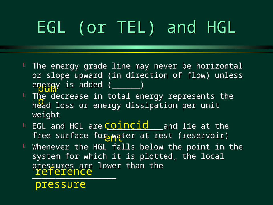
The energy grade line may never be horizontal or slope upward (in direction of flow) unless energy is added (______)
The decrease in total energy represents the head loss or energy dissipation per unit weight
EGL and HGL are ____________and lie at the free surface for water at rest (reservoir)
Whenever the HGL falls below the point in the system for which it is plotted, the local pressures are lower than the __________________

zz
Example HGL and EGL
z = 0
pump
energy grade line
hydraulic grade line
velocity head
pressure head
elevation
datum
2g
V2
2g
V2
pp
2 2
2 2in in out out
in in P out out T L
p V p Vz h z h h
g ga a
g g+ + + = + + + +
2 2
2 2in in out out
in in P out out T L
p V p Vz h z h h
g ga a
g g+ + + = + + + +

Bernoulli vs. Control Volume Conservation of Energy
Bernoulli vs. Control Volume Conservation of Energy
Free jetpipe
Find the velocity and flow. How would you solve these two problems?Find the velocity and flow. How would you solve these two problems?

Bernoulli vs. Control Volume Conservation of Energy
Bernoulli vs. Control Volume Conservation of Energy
Point to point along streamline Control surface to control surface
No frictional losses Has a term for frictional losses
Based on average velocity
Requires kinetic energy correction factor
Includes shaft work
ph
vg
ph
vg
11
12
22
22
2 2
2 2
2 2in in out out
in in P out out T L
p V p Vz h z h h
g ga a
g g+ + + = + + + +
2 2
2 2in in out out
in in P out out T L
p V p Vz h z h h
g ga a
g g+ + + = + + + +
Based on point velocity
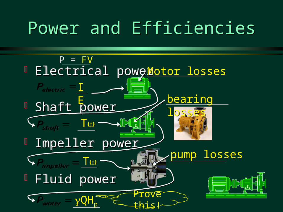
Power and EfficienciesPower and Efficiencies
Electrical power
Shaft power
Impeller power
Fluid power
Electrical power
Shaft power
Impeller power
Fluid power
electricP electricP
waterP waterP
shaftP shaftP
impellerP impellerP
IEIE
TT
TT
QHpQHp
Motor lossesMotor losses
bearing lossesbearing losses
pump lossespump losses
Prove this!
P = FV

Example: Hydroplant Example: Hydroplant
Q = 5 mQ = 5 m 33/s/sQ = 5 mQ = 5 m 33/s/s
2100 kW2100 kW
180 rpm180 rpm180 rpm180 rpm
116 kN·m116 kN·m116 kN·m116 kN·m
50 m50 m
Water power = ?Water power = ?total losses = ?total losses = ?efficiency of turbine = ?efficiency of turbine = ?efficiency of generator = ?efficiency of generator = ?
solutionsolution

Energy Equation ReviewEnergy Equation Review
Control Volume equation Simplifications
steady constant density hydrostatic pressure distribution across control
surface (cs normal to streamlines) Direction of flow matters (in vs. out) We don’t know how to predict head loss
Control Volume equation Simplifications
steady constant density hydrostatic pressure distribution across control
surface (cs normal to streamlines) Direction of flow matters (in vs. out) We don’t know how to predict head loss
2 2
2 2in in out out
in in P out out T L
p V p Vz h z h h
g ga a
g g+ + + = + + + +
2 2
2 2in in out out
in in P out out T L
p V p Vz h z h h
g ga a
g g+ + + = + + + +
Conservation of Energy, Momentum, and Mass
Conservation of Energy, Momentum, and Mass
Most problems in fluids require the use of more than one conservation law to obtain a solution
Often a simplifying assumption is required to obtain a solution neglect energy losses (_______) over a short
distance with no flow expansion neglect shear forces on the solid surface over a
short distance
Most problems in fluids require the use of more than one conservation law to obtain a solution
Often a simplifying assumption is required to obtain a solution neglect energy losses (_______) over a short
distance with no flow expansion neglect shear forces on the solid surface over a
short distance
to heatto heat

greatergreater
Head Loss: Minor Losses
Head (or energy) loss due to:outlets, inlets, bends, elbows, valves, pipe size changes
Losses due to expansions are ________ than losses due to contractions
Losses can be minimized by gradual transitions
Losses are expressed in the formwhere KL is the loss coefficient
Head (or energy) loss due to:outlets, inlets, bends, elbows, valves, pipe size changes
Losses due to expansions are ________ than losses due to contractions
Losses can be minimized by gradual transitions
Losses are expressed in the formwhere KL is the loss coefficient
2
2L L
Vh K
g=
2
2L L
Vh K
g=
2 2
2 2in in out out
in in P out out T L
p V p Vz h z h h
g ga a
g g+ + + = + + + +
2 2
2 2in in out out
in in P out out T L
p V p Vz h z h h
g ga a
g g+ + + = + + + +
Remember vena contracta
zin = zoutzin = zout
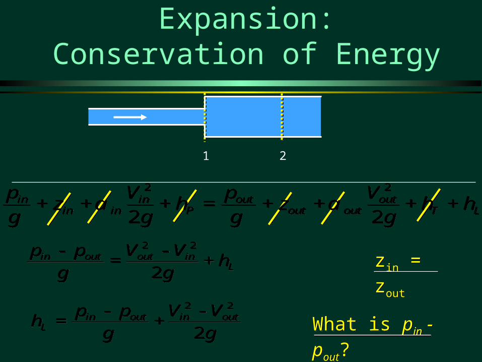
What is pin - pout?What is pin - pout?
Head Loss due to Sudden Expansion:Conservation of Energy
1 2
2 2
2in out out in
L
p p V Vh
gg- -
= +2 2
2in out out in
L
p p V Vh
gg- -
= +
2 2
2in out in out
L
p p V Vh
gg- -
= +2 2
2in out in out
L
p p V Vh
gg- -
= +
2 2
2 2in in out out
in in P out out T L
p V p Vz h z h h
g ga a
g g+ + + = + + + +
2 2
2 2in in out out
in in P out out T L
p V p Vz h z h h
g ga a
g g+ + + = + + + +

Apply in direction of flowApply in direction of flow
Neglect surface shearNeglect surface shear
Divide by (Aout )Divide by (Aout )
Head Loss due to Sudden Expansion:Conservation of Momentum
Pressure is applied over all of section 1.Momentum is transferred over area corresponding to upstream pipe diameter.Vin is velocity upstream.
Pressure is applied over all of section 1.Momentum is transferred over area corresponding to upstream pipe diameter.Vin is velocity upstream.
sspp FFFWMM 2121 sspp FFFWMM 2121
1 2
xx ppxx FFMM2121
xx ppxx FFMM2121
21x in inM V Ar=- 21x in inM V Ar=- 2
2x out outM V Ar= 22x out outM V Ar=
2 2 inout in
in out out
AV V
p p Agg
--
=
2 2 inout in
in out out
AV V
p p Agg
--
=
AA11
AA22
xx
2 2in in out out in out out outV A V A p A p Ar r- + = -2 2in in out out in out out outV A V A p A p Ar r- + = -

Head Loss due to Sudden Expansion
2 22 2
2
outout in
in in outL
VV V
V V Vh
g g
--
= +
2 22 2
2
outout in
in in outL
VV V
V V Vh
g g
--
= +2 22
2out in out in
L
V V V Vh
g- +
=2 22
2out in out in
L
V V V Vh
g- +
=
( )2
2in out
l
V Vh
g
-=
( )2
2in out
l
V Vh
g
-=
22
12
in inl
out
V Ah
g A
æ ö= -ç ÷è ø
22
12
in inl
out
V Ah
g A
æ ö= -ç ÷è ø
2
1 inL
out
AK
A
æ ö= -ç ÷è ø
2
1 inL
out
AK
A
æ ö= -ç ÷è ø
in out
out in
A VA V
=in out
out in
A VA V
=
Discharge into a reservoir?_________Discharge into a reservoir?_________
EnergyEnergy
MomentumMomentum
MassMass
KL=1KL=1
2 2
2in out in out
L
p p V Vh
gg- -
= +2 2
2in out in out
L
p p V Vh
gg- -
= +
2 2 inout in
in out out
AV V
p p Agg
--
=
2 2 inout in
in out out
AV V
p p Agg
--
=

Example: Losses due to Sudden Expansion in a Pipe (Teams!)
Example: Losses due to Sudden Expansion in a Pipe (Teams!)
A flow expansion discharges 2.4 L/s directly into the air. Calculate the pressure immediately upstream from the expansion
A flow expansion discharges 2.4 L/s directly into the air. Calculate the pressure immediately upstream from the expansion
1 cm1 cm 3 cm3 cm
We can solve this using either the momentum equation We can solve this using either the momentum equation or the energy equation (with the appropriate term for the or the energy equation (with the appropriate term for the energy losses)!energy losses)!
Solution

SummarySummary
Control volumes should be drawn so that the surfaces are either tangent (no flow) or normal (flow) to streamlines.
In order to solve a problem the flow surfaces need to be at locations where all but 1 or 2 of the energy terms are known
When possible choose a frame of reference so the flows are steady
SummarySummary
Control volume equation: Required to make the switch from Lagrangian to Eulerian
Any conservative property can be evaluated using the control volume equation mass, energy, momentum, concentrations of
species Many problems require the use of several
conservation laws to obtain a solution
Control volume equation: Required to make the switch from Lagrangian to Eulerian
Any conservative property can be evaluated using the control volume equation mass, energy, momentum, concentrations of
species Many problems require the use of several
conservation laws to obtain a solution
end

Example: Conservation of Mass(Team Work)
Example: Conservation of Mass(Team Work)
The flow through the orifice is a function of the depth of water in the reservoir
Find the time for the reservoir level to drop from 10 cm to 5 cm. The reservoir surface is 15 cm x 15 cm. The orifice is 2 mm in diameter and is 2 cm off the bottom of the reservoir. The orifice coefficient is 0.6.
CV with constant or changing mass. Draw CV, label CS, solve using variables starting with
to integration step
orQ CA 2gh= orQ CA 2gh=
ˆcs cv
dA dVt
r r
× =-¶ò òV n̂
cs cv
dA dVt
r r
× =-¶ò òV n

Example Conservation of MassConstant Volume
Example Conservation of MassConstant Volume
hh
0 ororresres AVAV 0 ororresres AVAV
cs1cs1
cs2cs2
dt
dhVres
dt
dhVres
ororor QAV ororor QAV
02 ghCAAdt
dhorres 02 ghCAA
dt
dhorres
ˆcs cv
dA dVt
r r
× =-¶ò òV n̂
cs cv
dA dVt
r r
× =-¶ò òV n
1 2
1 1 1 2 2 2ˆ ˆ 0cs cs
dA dAr r× + × =ò òV n V n1 2
1 1 1 2 2 2ˆ ˆ 0cs cs
dA dAr r× + × =ò òV n V n

Example Conservation of MassChanging Volume
Example Conservation of MassChanging Volume
hh
or or
cv
V A dVt
=-¶ òor or
cv
V A dVt
=-¶ ò
cs1cs1
cs2cs2
ororor QAV ororor QAV
02 ghCAAdt
dhorres 02 ghCAA
dt
dhorres
resor or
A dhdVV A
dt dt=- =- res
or or
A dhdVV A
dt dt=- =-
ˆcs cv
dA dVt
r r
× =-¶ò òV n̂
cs cv
dA dVt
r r
× =-¶ò òV n

Example Conservation of MassExample Conservation of Mass
th
hor
res dth
dh
gCA
A
002
th
hor
res dth
dh
gCA
A
002
thhgCA
A
or
res 2/10
2/122
thhgCA
A
or
res 2/10
2/122
( )
( ) ( ) ( )( ) ( )( )
21/ 2 1/ 2
22
2 0.150.03 0.08
0.0020.6 2 9.8 /
4
mm m t
mm s
p
-- =
æ öç ÷è ø
( )
( ) ( ) ( )( ) ( )( )
21/ 2 1/ 2
22
2 0.150.03 0.08
0.0020.6 2 9.8 /
4
mm m t
mm s
p
-- =
æ öç ÷è ø
st 591 st 591

Pump HeadPump Head
hhpp
2
2in
in
Vg
a2
2in
in
Vg
a
2
2out
out
Vg
a2
2out
out
Vg
a2
2
2
2
in inin in P
out outout out T L
p Vz h
g
p Vz h h
g
ag
ag
+ + + =
+ + + +
2
2
2
2
in inin in P
out outout out T L
p Vz h
g
p Vz h h
g
ag
ag
+ + + =
+ + + +

Example: VenturiExample: Venturi

Example: VenturiExample: Venturi
Find the flow (Q) given the pressure drop between section 1 and Find the flow (Q) given the pressure drop between section 1 and 2 and the diameters of the two sections. Draw an appropriate 2 and the diameters of the two sections. Draw an appropriate control volume. You may assume the head loss is negligible. control volume. You may assume the head loss is negligible. Draw the EGL and the HGL. Draw the EGL and the HGL.
11 22
h h

Example VenturiExample Venturi
2 2
2 2in out out inp p V V
g gg g- = -
2 2
2 2in out out inp p V V
g gg g- = -
42
12
in out out out
in
p p V dg dg g
é ùæ ö- = -ê úç ÷è øê úë û
42
12
in out out out
in
p p V dg dg g
é ùæ ö- = -ê úç ÷è øê úë û
( )4
2 ( )
1in out
out
out in
g p pV
d dg
-=
é ù-ë û( )4
2 ( )
1in out
out
out in
g p pV
d dg
-=
é ù-ë û
( )4
2 ( )
1in out
v out
out in
g p pQ C A
d dg
-=
é ù-ë û( )4
2 ( )
1in out
v out
out in
g p pQ C A
d dg
-=
é ù-ë û
VAQ VAQ
in in out outV A V A=in in out outV A V A=
2 2
4 4in out
in out
d dV V
p p=
2 2
4 4in out
in out
d dV V
p p=
2 2in in out outV d V d=2 2in in out outV d V d=
2
2out
in outin
dV V
d=
2
2out
in outin
dV V
d=
2 2
2 2in in out out
in in P out out T L
p V p Vz h z h h
g ga a
g g+ + + = + + + +
2 2
2 2in in out out
in in P out out T L
p V p Vz h z h h
g ga a
g g+ + + = + + + +

Fire nozzle: Team WorkFire nozzle: Team Work
Identify what you need to know
Determine what equations you will use
Identify what you need to know
Determine what equations you will use
8 cm8 cm2.5 cm2.5 cm
1000 kPa1000 kPa
P2, V1, V2, Q, M1, M2, Fss
Bernoulli, continuity, momentum

Find the VelocitiesFind the Velocities
2 21 1 2 2
1 22 2p V p V
z zg gg g
+ + = + +2 2
1 1 2 21 22 2
p V p Vz z
g gg g+ + = + +
2 21 1 2
2 2p V V
g gg+ =
2 21 1 2
2 2p V V
g gg+ = 2 2
1 1 2 2V D V D=2 21 1 2 2V D V D=
2 21 2 1
2 2p V V
g gg= -
2 21 2 1
2 2p V V
g gg= -
4
2 222 1
1
DV V
D
æ ö=ç ÷è ø
4
2 222 1
1
DV V
D
æ ö=ç ÷è ø
422 2
11
12
V Dp
Dr
æ öæ ö= -ç ÷ç ÷è øè ø
422 2
11
12
V Dp
Dr
æ öæ ö= -ç ÷ç ÷è øè ø
12 4
2
1
2
1
pV
DD
r
=é ùæ ö
-ê úç ÷è øê úë û
12 4
2
1
2
1
pV
DD
r
=é ùæ ö
-ê úç ÷è øê úë û

Fire nozzle: SolutionFire nozzle: Solution
section 1 section 2D 0.08 0.025 m
A 0.00503 0.00049 m2
P 1000000 0 PaV 4.39 44.94 m/s
Fp 5027 N
M -96.8 991.2 N
Fssx -4132 N
Q 22.1 L/s
2.5 cm2.5 cm8 cm8 cm
1000 kPa1000 kPa
force applied by nozzle on water
Is this the force that the firefighters need to brace against? _______
Which direction does the nozzle want to go? ______
NO!
1 21 2x x x x xss x p pF M M F F= + - - -W1 21 2x x x x xss x p pF M M F F= + - - -W

ReflectionsReflections
What is the name of the equation that we used to move from a system (Lagrangian) view to the control volume (Eulerian) view?
Explain the analogy to your checking account. The velocities in the linear momentum equation are
relative to …? Why is ma non-zero for a fixed control volume? Under what conditions could you generate power from a
rotating sprinkler? What questions do you have about application of the linear
momentum and momentum of momentum equations?

Temperature Rise over Taughanock Falls
Temperature Rise over Taughanock Falls
Drop of 50 meters Find the temperature rise
Drop of 50 meters Find the temperature rise
netin
L
p
gh qT
c
+D =
netin
L
p
gh qT
c
+D =
KKg
J4184
m 50m/s 9.8 2
T
KKg
J4184
m 50m/s 9.8 2
TKT 117.0 KT 117.0
( )netin
p out in
L
c T T qh
g
- -=
( )netin
p out in
L
c T T qh
g
- -=

HydropowerHydropower
pQHP g= pQHP g=
( ) ( ) ( )3 39806 / 5m / 50m 2.45waterP N m s MW= =( ) ( ) ( )3 39806 / 5m / 50m 2.45waterP N m s MW= =
2.1000.857
2.45total
MWe
MW= =
2.1000.857
2.45total
MWe
MW= =
( ) 2 1min0.116 180 2.187
min 60
2.1870.893
2.452.100
0.962.187
turbine
turbine
generator
rev radP MNm MW
rev s
MWe
MWMW
eMW
pæ ö= =è ø
= =
= =
( ) 2 1min0.116 180 2.187
min 60
2.1870.893
2.452.100
0.962.187
turbine
turbine
generator
rev radP MNm MW
rev s
MWe
MWMW
eMW
pæ ö= =è ø
= =
= =

Solution: Losses due to Sudden Expansion in a Pipe
Solution: Losses due to Sudden Expansion in a Pipe
A flow expansion discharges 2.4 L/s directly into the air. Calculate the pressure immediately upstream from the expansion
A flow expansion discharges 2.4 L/s directly into the air. Calculate the pressure immediately upstream from the expansion
1 cm1 cm
3 cm3 cm
AA
VV
1
2
2
1
p V V Vg
1 22
1 2
p V V V1 22
1 2 c h
p pV V
AA
g1 2
22
12 1
2
V
m s
mm s1
3
2
0 0024
0 01
4
30 56 . /
.. /
a fV m s2 3 39 . /
p kg s m s m s m s121000 3 39 30 56 3 39 / . / . / . /a fa f a fa fd i
p kPa1 92

Scoop ProblemScoop Problem
stationary water tank
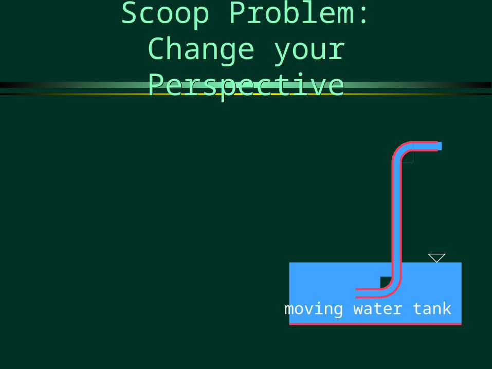
moving water tank
Scoop Problem:Change your Perspective
Scoop Problem:Change your Perspective

Scoop Problem:Be an Extremist!Scoop Problem:Be an Extremist!
Very short riser tubeVery short riser tube
Very long riser tubeVery long riser tube

Scoop Problem:‘The Real Scoop’Scoop Problem:
‘The Real Scoop’
stationary water tank
stationary water tank