finishing and machining plastics - rochester institute of...
TRANSCRIPT

Finishing and Machining Plastics
Many plastic products will require some degree of machining and finishing after they have been processed and before they are put in the mar- ketplace.
A basic purpose of many finishing and ma- chining operations is to remove such imperfec- tions as scratches, dents, dull spots, marks of misalignment, slight ridges where the mold sections joined, or distinct flash. In transfer or injection moldings, rough spots may be left by breaking off the gates. Extruded pieces may ex- hibit longitudinal scratches from the edge of the extrusion die. Thermoformed pieces may show surface defects that were present in the original sheet. Cast plastic formed in a rigid mold will have a slight mark where the halves of the mold are joined; even where flexible molds are used, a gate mark may be left where the fluid plastic entered the mold.
Many finishing operations on molded arti- cles can, of course, be avoided by careful de- sign of the product or the mold (e.g., placing flash lines and gates in accessible positions); but where finishing or machining is necessary, a wide range of techniques are available for use with plastics, including tumbling, filing, sand- ing, buffing, tapping, turning, sawing, pierc- ing, trimming, routing, grinding, and so on.
Obviously, repair work and defect removal are not the only reasons for finishing and ma- chining. In some applications, it may be nec-
Reviewed and updated by Donald S . Swavely, Polymer Corporation, Reading. PA.
essary to saw, drill, tap, and so on, simply to prepare the plastic product for assembly or mounting. In other instances, machining and finishing may be used to meet very narrow tol- erances by molding a critical dimension over- size, then machining it down to the desired tol- erances.
Machining also can be useful in the early stages of design engineering for the creation of prototypes or in low-volume production. Pro- totypes can provide material and performance data to aid in material selection, or in success- ful final part production if the material has al- ready been decided upon. Short production runs can be entirely machined, practically and eco- nomically, instead of committing relatively large sums of money for complex molds or dies. High-speed automatic screw machines, for example, are increasingly being used for low-volume runs.
Another aspect of the finishing operation is the decorating of the plastic part, which will be discussed in Chapter 26. This chapter is con- cerned with the various aspects of finishing and machining other than decorating.
FINISHING
In the general nomenclature, finishing opera- tions sometimes are distinguished from ma- chining operations in that they include such techniques as filing, grinding, sanding, buff- ing, and polishing, as used to finish-off, smooth-out, or polish-up the plastic part. Of
657

658 SPI PLASTICS ENGINEERING HANDBOOK
course, such a distinction is rather vague in that some of the so-called finishing operations, such as grinding, also can be used to fashion a part (i.e., machine it to a different shape), just as machining operations, such as cutting, can be used to trim off flash (i-e., finish the product). For purposes of this discussion, however, we shall follow this arbitrary distinction, assuming that the reader will be able to apply any of the techniques covered for his or her own particu- lar needs.
Filing
Files are used for finishing molded articles, and for beveling, smoothing, burring, and fitting the edges and comers of sheets of plastic. For re- moval of flash, tumbling is to be preferred if feasible, but the shape, size, or contours of the article may require filing to remove both heavy and thin flash as well as gates of a heavy sec- tion, or burrs left by machining operations such as drilling and tapping. Filing by hand is more costly than using special machine setups, but may be more economical on short runs.
Selection of the proper file is of great impor- tance, as the shape, cut, size, and pattern of the file will determine the ease and speed of re- moval of stock, as well as the appearance of the filed surface.
The type of file selected must be adapted to the plastic-its hardness, brittleness, flexibil- ity, and heat-resistance. The size and shape of the file are determined by the size, shape, and contour of the article to be filed. For removal of flash, files should have very sharp, thin- topped teeth that will hold their edge, well- rounded gullets to minimize the tendency to clog, and the proper rake for clearing the chips.
Machine Filing. Removal of flash from cir- cular or cylindrical articles in large production runs sometimes is accomplished by semiauto- matic machines. A circular revolving table car- ries from six to ten work-holding stations past a series of fixed stations equipped to remove flash, to polish, and to buff. The work-holding stations revolve on their individual axes as they pass the workstations. If the articles are per- fectly round, the workstations may be equipped
with tool-holders to accommodate files, and so on. If the articles are slightly out of round, or vary in size, as may be the case with pieces produced in multicavity molds, then motor-dri- ven sanding belts, spring-loaded files, or buff- ing wheels are used. The efficiency of these machines is limited by the quality of the mold- ing. Excessively heavy flash or even a slight mismatch will seriously reduce production or make hand finishing necessary.
The edges of round articles can be finished in a simple button machine, consisting of a drive chuck that rotates at high speed and can be moved axially by means of a pedal. The work is put against a stationary center, the drive chuck is brought forward to engage and rotate the work, and then the operator applies a file, usually about 70" from the flash plane, to re- move the fin. Frequently as many as three dif- ferent flash edges may be smoothed in one han- dling. When the pedal is released, the work falls into a tray, and the operator inserts an- other piece.
An excellent way to remove material rapidly is by using a rotary file or burr. Standard me- dium-cut, high-speed steel burrs operated at 800 to 1000 surface feet per minute are quite effective. Ground burrs provide better chip clearance than hand-cut rotary files and are, therefore, preferred. Carbide burrs offer no ad- vantage over high-speed steel burrs. Because of their tooth geometry, carbide burrs remove less material than the high-speed steel burrs at the same speed, and when operated at higher speeds, tend to cause excessive frictional heat buildup.
Filing Thermoplastics. With thermoplastics, filing has become less popular than it was in the early days, as flash is more effectively re- moved by the three-square scrapers described below.
For the soft thermoplastics, fine files should be avoided, because they become clogged. Coarse, single-cut, shear-tooth files should be used, with teeth cut on a 45" angle, and in flat or half-round shape. The combination of coarse teeth and a long angle promotes self-cleaning. Shear-tooth files are used with long sweeping light strokes, to avoid running off of the work.

FINISHING AND MACHINING PLASTICS 659
Clogging is not encountered with the harder thermoplastics, and fine files may be used (al- though the shear-type, coarser files still are generally recommended). It is also well to note that some plastics with unusual toughness and abrasion resistance, such as nylon, are not eas- ily filed.
For filing edges of sheet stock, milled-tooth files are recommended. The files should be held at approximately a 20" angle with the edge.
In general, when filing thermoplastics, it would be wise to check with suppliers on han- dling the various types, as some distinctions are evident. For ABS, for example, files are usu- ally of the coarse texture type. For polycarbon- ate, a single-hatched file is better than a cross- hatched file because the latter has a tendency to clog under heavy pressure. A No. 2 pillar file has no tendency to clog when used with light pressure. For acetal, best results are ob- tained by using the coarsest file consistent with the size of the surface and the finish required. Milled curved-tooth files with coarse, single- cut, shear-type teeth are particularly suitable.
A more up-to-date method of removing flash and parting lines and breaking sharp comers is to use a high-speed router equipped with a solid carbide or carbide-tipped cutter. For flat or square stock, it is recommended that the router be mounted to a table with guides and that the work be moved instead of the router.
Scraping Thermoplastics. Scraping involves smoothing a plastic surface by the use of a sharp-bladed tool, which is held so that the blade rides over the surface and has no ten- dency to dig under it.
A standard scraper is a three-edged tool of triangular cross section, the sides making up a scraping edge (at an angle of 60"). The blade is tapered so that the scraping edge runs from a fairly long straight section at the handle end to a curved section near the point. This vari- ation in shape allows the careful scraping of a great variety of straight, concave, and convex surfaces.
Another type of scraper contains a small tri- angular sharp-edged insert mounted on the end of a handle. The insert or scraper is secured by retracting a collet, inserting the scraper, and re-
leasing the collet. A variety of inserts are avail- able, depending on the type of edge or material to be deburred or deflashed. The scraper is drawn by hand along either a straight or a con- toured work edge, thereby removing a light but continuous curl of material from the entire edge. The result is a smooth, g to 3 inch, chamfered edge.
As with the other tools, the edges of the scraper must be free from burrs, dents, or scratches, which might mar the surface of the plastic.
I I
Filing Thermosetting Plastics. Articles molded from thermosetting plastics always re- quire some finishing operation for removal of flash from parting lines (or the removal of gates).
Flash should be filed off in such a way as to break it toward a solid portion rather than away from the main body, in order to prevent chip- ping. The file is pushed with a firm stroke to break off the flash close to the body, and then filing is continued to smooth the surface.
Selection is made by trial and error; so it is well to have a variety of files on hand.
Mill files in bastard and western cuts are used extensively to remove the flash from flat or convex surfaces of molded articles and on the comers and edges of sheets, to remove the burrs from sawing, or to bevel the comers. The west- em cut is slightly the coarser.
Milled-tooth files are recommended for large areas or for beveling the comers and edges of large sheets. They are relatively coarse files with curved teeth, and are available in both flexible and rigid types.
Various shapes of Swiss-pattern files are used, coarse enough to effect rapid removal of material, and fine enough to leave a good fin- ish. These small files of various shapes, in cuts from No. 00 to No. 4, are used for small, in- tricate moldings, in which the surfaces to be filed are hard to reach. Round and half-round files are used for cleaning out holes or slots with rounded surfaces; knife and warding files are used to reach down between flutes and into nar- row slots and grooves.
Files are designed to cut in one direction only; pressure should be applied in that direc-
660 SPI PLASTICS ENGINEERING HANDBOOK
tion, and relieved on the return stroke. Expe- rience has shown that on some fine, intricate articles a steady pressure on both strokes may result in a better finish, but it is damaging to the file. As much as possible of the filing sur- face, on both length and width, should be used, so that the file will wear uniformly.
The life of the file is greatly shortened by improper selection, use, and care. Because many resins and fillers cause rapid wear of cut- ting tools, it is imperative that the files be given proper care to retain their sharpness. Proper care must be given in storage also. Files should never be thrown into a drawer with other tools, or stacked on top of each other, as such treat- ment ruins the cutting edge of the teeth. They should be stored standing with the tangs in a row of holes, or hanging on racks by their han- dles, and in a dry place so that they will not rust. Files should be kept clean of filings or chips, which collect between the teeth during use, by tapping the end after every few strokes. A file card or brush should be used to remove the chips before storage. Oil or grease is re- moved by applying chalk and then brushing. When a file becomes dull, but is otherwise in good condition, it should be sharpened. Files can be resharpened as often as four times, even though they do not then do as good a job as when new.
Tumbling
Thermoplastics. Tumbling is .used to round comers, to remove stumps of gates, and to ap- ply finish to surfaces. It is the cheapest way of doing these things, for the equipment is not ex- pensive, and the only labor involved is in the loading and unloading of barrels. It is appli- cable chiefly to small objects that do not have projections that are easily broken off. Tum- bling does not produce as high a finish as that obtainable by ashing and polishing, but for many articles a very high polish is not neces- sary and is not worth the higher labor cost in- volved.
The articles to be tumbled are placed in bar- rels, 20 to 30 inches in diameter, which may be divided into two or more compartments to permit the handling of two or more colors or
shapes simultaneously. The barrels are mounted on a horizontal axis and are usually run at a speed of 15 to 30 rpm.
Abrasives and hardwood pegs are put into the barrels with the articles to be tumbled. The pegs serve to rub the abrasive against the articles during the tumbling. Sawdust and pumice are used in the first stage because of their rapid ab- rasive action; finer abrasives and polish are used later to give better finishes.
Tumbling of thermoplastics can be done wet, as well as dry. For wet polishing of a thermo- plastic such as acetal, for example, a system might consist of aluminum oxide chips with a high-sudsing, burnishing compound (i.e., con- taining soap, detergent, alkaline cleaning agents, etc).
Automatic vibratory finishing machines are also available.
Thermosetting Plastics. Tumbling is used on all kinds of thermosetting materials to remove flash. It is done in barrels of various types, with several different materials as filing agents.
A cylindrical ( “cement-mixer” ) barrel, running at speeds of 15 to 25 rpm, is used for light articles that have little or very thin flash. The articles are allowed to roll by themselves, from 2 to 5 minutes as necessary.
An octagonal barrel with alternate closed and open sides, running horizontally, is used for heavier articles and where more positive action is needed. The open sections are covered by screens of suitable coarseness to let the frag- ments of flash fall out. Lignum vitae balls from 5 to 1 inch in diameter are used to give a rolling action to the articles and to prevent chipping. It has been found that a mixture of two parts of balls to one part of moldings, by volume, gen- erally gives good results. Hardwood blocks or scrap molded parts also are used on some jobs. The speed of this barrel should be variable from 5 to about 30 rpm. The time required varies with the work, some jobs running as long as 2 to 3 hours.
Tumbling may be used to reduce the size of molded articles. This is done in a closed barrel running at a fairly high speed, and employs a cutting agent. Rubber impregnated with an ab- rasive is cut into various shapes and sizes and
I

FINISHING AND MACHINING PLASTICS 661
tumbled with the articles to give a satiny finish without a harsh cutting action. For fast removal of stock, strips of abrasive cloth or abrasive pa- per, mixed with the articles, are used. The bar- rel may be lined with abrasive cloth. For very light cuts, especially before polishing, pumice and small pegs are used. Octagonal barrels run- ning at 20 to 35 rpm have proved best for this work.
With articles having grooves or projections, it is more difficult to achieve a uniform com- plete polishing, and the polishing agent tends to accumulate in grooves or other pockets on the surface. Such articles are best polished by being tumbled in barrels with string mops that have been impregnated and coated with spe- cially compounded wax by being tumbled in clean barrels with balls of the wax. The tum- bling together of articles and mop is done in a closed octagonal barrel having no screens, and no metal on the inside, which would scratch the surface of the articles. The barrel, on a hori- zontal axis, is rotated at speeds from 15 rpm (for large articles) up to 30 rpm (for small ar- ticles).
Besides plain tumbling, most thermoset de- flashing is accomplished in machines using the impellor wheel design. Using nonabrasive me- dia such as vegetable grain (walnut shell, corn cob, apricot pit, etc.) or plastic pellets (such as polycarbonate), these machines effectively handle large loads in a matter of minutes. In
essence, these units are based on the use of a conveyor that carries the articles, in tumbling motion, through the stream of pellets projected at high velocity by a rotating bladed wheel (Fig. 23-1). A modified version of this type of equip- ment utilizes a rotary table or platform arrange- ment to pass parts under the impellor wheel without tumbling (Fig. 23-2). Production rates are slower with this type of equipment, but damage to delicate or fragile parts is avoided by eliminating the tumbling operation.
Deflashing also can be carried out by using pressure blast type systems with individual blasting guns. A number of configurations can be used for handling parts, from simple hand machines through batch-type tumbling systems to the use of conveyors, rotary tables, and so on.
Cryogenic deflashers use liquid nitrogen to freeze flash on molded parts, making it more brittle and, thus, easier to break off. The parts are tumbled or vibrated, either alone or with a deflashing medium.
Grinding and Sanding
These operations, if conducted dry, require an exhaust system to dispose of dust.
Thermoplastics. Standard sanding machines of belt and disc types, run wet or dry, are used for form sanding, or for long production runs.
Fig. 23-1. Articles are camed by conveyor through stream of pellets.

662 SPI PLASTICS ENGINEERING HANDBOOK
I
Fig. 23-2. Parts on a rotary table pass under an impellor wheel without tumbling
A variable-speed control provides the proper speed in accordance with the amount of mate- rial to be removed.
Belts carrying coarse abrasive, and run dry, may be used for fast, rough cutting, if the speed is kept down to avoid excessive heating. In most cases, however, particularly in fine sand- ing, belts are run wet, as a precaution against overheating.
On methyl methacrylate resin (acrylic), the finest sandpaper that will remove the scratch or other defects (no coarser than grade 320) is used first. The paper, which should be of a water- proof type, is wrapped around a soft block of felt or rubber, and the area is rubbed lightly with a circular motion, using water, or soap and water, as a lubricant. An area having a diam- eter two or three times the length of the defect should be followed by similar treatment with progressively finer grades of sandpaper (grade 360A, 400A, and 500A, or 600A), each of which removes the deeper scratches left by the preceding one. The plastic must be washed after each sanding operation. Where a large amount of polishing is to be done, ashing compounds may be used in place of sandpaper.
When polystyrene is sanded, the heat devel- oped should be kept to a minimum to prevent gumming and loading of the abrasive belt or disc. For this reason, wet sanding is the best type of operation. Care should be exercised in filtering the coolant to prevent abrasive grit
contamination of the surface of the molded ar- ticle.
A vertical belt sander is most frequently used, with belts having grits to suit the opera- tion. For rough work, 80 grit is suggested. For medium and fine work, 220 to 280 grit and 400 to 600 grit belts are best.
ABS can be centerless, surface, and spindle ground or sanded. Many abrasives can be used to obtain the desired stock removal or surface finish. Coolants and lubricants used to reduce frictional heat include water, soap, detergents, or soluble oil solutions. A variety of industrial abrasives are available- for grinding parts to de- sired flatness or other preferred shapes. Wet sanding is preferable, as it dissipates heat and retards loading of the abrasive belt. Silicon car- bide belts or pads of No. 82 to 130 grit are ideal. Light pressure should be used to avoid overheating. Surface speeds of grinding should be determined by starting at speeds of 4500 surface feet per minute (sfpm) and adjusting the surface speed, feed rate, pressure, grit size, and coolant to obtain the desired finish or stock re- moval rates. Avoid excessive heat generation, or melting may occur.
Acetals can be wet-sanded by using conven- tional belt and disc sanding equipment. Mod- erate feeds should be used in sanding to prevent overheating. After sanding to a smooth finish, acetal can be buffed to a high surface luster.
In working with polycarbonate, sandpaper or

FINISHING AND MACHINING PLASTICS 663
silicon carbide (emery) abrasive-coated belts may be used to remove sprue projections or toolmarks or for flat-surfacing sheet stock. Coarse abrasives will produce scratches that are difficult to remove, whereas too-fine grades will cause the belts to fill. For a scratch-free, highly polished surface, a grit size not over No. 180 is suggested. Hence, it may be desirable to use a coarse-grit sandpaper first and follow with a finer one. Belt speeds of approximately 3000 sfpm are adequate, but somewhat faster speeds (4000 sfpm) can be used so long as the pressure applied is not excessive.
Hand sanding must be done with light pres- sure in order to avoid clogging. especially with extremely fine grades. For example, 100 grit carborundum paper works well with light pres- sure, but clogs with heavy pressure. A 240 grit paper exhibits slight clogging even with very light pressure, but continues to produce a fine satin finish. Crocus cloth also shows a ten- dency to clog, but the use of kerosene lubricant prevents clogging and produces a fine satin fin- ish.
Thermosetting Plastic. Belt sanding is com- monly used for the removal of heavy flash and sprue projections, and for flat surfacing and beveling. The belts should carry a silicon car- bide abrasive bonded by waterproof synthetic resin. Popular grit sizes are 50, 120, 180, 220, and 400-the coarse for heavy flash and sprues, the fine for lighter operations. Speeds recom- mended are from 2000 to 5000 linear fpm, but 4000 is most commonly used.
With a good exhaust system to remove dust and do some cooling by pulling air past the edge being sanded, thermosetting plastics can be successfully sanded at medium speeds on dry belts, thus avoiding the washing and drying re- quired after wet sanding. However, wet sand- ing offers the advantages of freedom from dust and overheating, longer life of belts, freedom from clogging of the belt, and the finer surface produced because of the lubrication.
It is seldom necessary to resort to sanding the surfaces of well-machined pieces, but sand- ing can be done with any good abrasive cloth or abrasive paper that can be used in belt form or in rotating discs. The finer the paper and the
slower the cutting, the less pronounced are the marks left by the abrasive. Facets and other surfaces can be cut in this way, with care to avoid overheating and discoloring the work. The surface speed for sanding cast phenolics is about the same as, or slightly less than, that for sanding wood.
Ashing, Buffing, and Polishing
The finishing department requires polishing lathes, buffing wheels, and suitable composi- tions for the ashing, polishing, cutdown buff- ing, and luster buffing that may be required.
Lathes for ashing, buffing, and polishing are available in types ranging from low-powered bench models, which are essentially converted bench grinders, to 50-hp floor models,
For finishing plastics a popular machine is a 2- or 3-hp floor-type lathe, with motor in the base and V-belt drive. This is preferred over the motor-on-spindle lathe because its speed can be changed by merely changing the diam- eters of the pulleys. Where speeds must be changed frequently, variable-speed lathes are available, in 3-, 5-, and 7$hp sizes, which per- mit changes of speed between 1500 and 3000 rpm, generally without stopping the machine. With these machines, it is possible to operate at the most efficient peripheral speed, regard- less of the diameter of the buff.
For production buffing of articles of simple contours, automatic buffing machines are avail- able, which must, however, be engineered for the particular job.
All dry buffing and polishing operations re- quire an efficient exhaust system. Suitable sheet metal hoods should enclose as much of the wheel as is practicable, and be connected to the exhaust piping. The exhaust should pass through a dust-collector rather than to open air. Because many of the dusts are combustible, care should be taken so that, if steel inserts are ground, incandescent metal particles are not drawn into the exhaust system.
Buffing wheels for finishing plastics are gen- erally made up of sections of muslin discs, either with or without sewing, depending on the flexibility required. The cloth should be a high- count sheeting, such as 84 x 92, for the faster

664 SPI PLASTICS ENGINEERING HANDBOOK
cutting, and a lower count, such as 64 x 68, for buffing and polishing. For waxing, canton flannel and 48-48 muslin are both very popular.
Where the contours of the article are regular, and fast cutting is desired, the buffing wheel is composed of sewed buffing sections with stitching spaced at or inch. Wider spacings, and narrower, down to inch, are available. The wider spacings give the softer wheels. The next softer medium is the pocketed or folded buff, which presents pockets of cloth to the work and which makes for greater cooling of the surface, a faster cut than that given by a loose full-disc buff, and greater flexibility than that of conventional sewed buffs. Loose buffs made of full discs of muslin, while not cutting as fast as these, have a greater flexibility and give a smoother, more even, intermediate fin- ish than do the harder wheels, and are generally to be preferred, especially for articles with curved or irregular contours.
For special cases, extremely soft wheels are needed, such as the packed buff or the string brush. The packed buff is made up to large discs of cloth alternated with smaller discs in the pro- portion of 1 : 1, 2 : 1, or 1 : 2 , depending on the degree of hardness needed. The string brush is like a bristle brush, with cotton string substi- tuted for the bristles. The wheel offers the max- imum in flexibility, and in conjunction with greaseless compound is recommended for smoothing the edges of intricate articles.
Thermoplastics. In the ashing and polishing of thermoplastics, overheating must be care- fully avoided because it may soften and distort the surface into ripples. Hence, it is necessary to avoid excessively hard buffing wheels, ex- cessive speed of wheels, and excessive pres- sure of the work against the wheel.
Ashing is frequently required for the re- moval of “cold spots,” teardrops, deep scratches, parting lines, and so on, from irreg- ular surfaces that cannot be smoothed by wet sanding. A satin-smooth but dull surface is usually produced, requiring further finishing.
For ashing, wet pumice, grade No. 00 to No. 1, is used, on a loose muslin buff running at about 4000 linear fpm. The buff is often packed to increase its flexibility. The buff must be well
hooded because the wet pumice does not ad- here to it and tends to be thrown off. After wet ashing, the articles must be washed and dried before being polished.
As wet ashing is essentially a messy opera- tion, attempts are continually being made to get more cut in a buffing operation than is usual in cut-down buffing, so as to obviate the need for wet ashing. Certain commercial compounds are available that perform a fast cutting job, which can be called semi-ashing, on cellulose acetate, cellulose acetate butyrate, and acrylics.
For the buffing of thermoplastics, fine silica powders in special grease binders, differing considerably from mixtures that have been de- veloped for finishing metals, generally are most successful. Compositions must be formulated to give sufficient lubrication to prevent exces- sive heating. Pocketed and ventilated buffs are in aid in the prevention of overheating, al- though soft packed buffs are preferred for final luster buffing. Speeds generally run from 3000 to 4000 surface fpm.
Thermoplastics sometimes can be polished with greaseless compounds such as are used with thermosetting resins, but only with very soft wheels and with special caution against overheating.
ABS. In buffing ABS, a two-step method is the general practice. First, the part is cut down or polished, using commercially available wheels made of unbleached cotton discs. The second step involves wiping or coloring to in- crease the luster, using the same kind of wheels. Both the polishing and the wiping wheel should be about 6 inches thick and run at 1200 to 3000 rpm. A final softer wheel, kept free of polishing compound, is used for finish- ing off or wiping.
For ashing, a high-speed wheel (400 sfpm), built up of muslin discs that have been sewn together, is employed. Water and pumice are used for the cutting action and heat production.
In polishing ABS, an exceptionally high- gloss finish may be obtained by the use of mus- lin discs, felt, or sheepskin, with various pol- ishing compounds. Detergents and soap solu- tions are used to reduce frictional heat and static electricity buildup.
Aceruf. The ashing operation removes deep

FINISHING AND MACHINING PLASTICS 665
scratches, parting lines, and harsh surface im- perfections. In many instances, the ashing op- eration in buffing can be bypassed if the surface imperfections on the part are not severe. Ash- ing is done on a wheel made up of alternating 12- and 6-inch-diameter muslin discs wetted with a slurry of pumice and water. The wheel speed during the operation should be kept at approximately 1000 rpm. The acetal part should be held lightly against the wheel and kept in constant motion to prevent burning and irreg- ular ashing.
The polishing and wiping operations are car- ried out on the same type of buffing wheel as is used for ashing. Instead of using a wet wheel, however, one-half of the wheel should be op- erated dry and the other half-lubricated with a polishing compound, such as jeweler’s rouge. The acetal part should first be held against the lubricated half for polishing, and then wiped clean of polishing compound with the dry half. Wheel speeds of 1000 to 2000 rpm are sug- gested.
Sfyrene. Ashing wheels are built up, alter- nating spaces and discs from muslin. A suitable mixture of #00 pumice mud is used as an ab- rasive and may be applied to the wheel.
In buffing, two operations are used. The first consists of polishing the piece, or “cutting it down.” The second involves wiping or “col- oring” to increase the luster. Wheels for the first operation usually consist of unbleached cotton discs laid up alternately with two layers of 5-inch and two layers of 12-inch discs. The wiping wheel is composed of two layers of 12-inch and four layers of 5-inch unbleached cotton discs laid up alternately. Both wheels should be approximately 6 inches thick and run at about 1200 to 3000 rpm.
After polishing the piece with a suitable compound, such as a rough or greasy tripoli, a clean wheel that is made up softer than the pol- ishing wheel is used for finishing off or wiping. This wheel should be kept clean, or it will tend to accumulate compound. Line or chalk “col- oring” compound can be applied to the wiping wheel to remove any grease and bring out a lus- trous surface. The pieces need only be wiped on this wheel.
In polishing styrene, care should be exer-
cised to prevent a temperature rise to over 175”F, or else crazing and gumming will oc- cur. As a precaution, avoid polishing under too great a pressure, on too stiff a wheel, or with insufficient cooling.
Thermosetting Plastics. For thermosetting plastics, a polishing operation with greaseless compositions on muslin buffing wheels is rec- ommended for the removal of surface defects, light or residual flash, and marks from machin- ing operations, and for the smoothing of irreg- ularities left by the belt sander. The cutting face is formed and maintained by periodic transfer of greaseless compound in bar form to the face of the revolving wheel. A wheel coated in such a manner presents a faster-cutting face similar to the surface of emery cloth, and because of its resilience has the ability to smooth irregu- larly shaped parts without distorting or goug- ing. Although conditions and materials differ somewhat with the individual job, it is com- mon procedure to use a No. 220 greaseless compound on a full-disc loose muslin buff at 5000 linear fpm.
Cut-down buffing is a procedure that con- verts a dull sanded surface into a smooth semigloss, preliminary to final luster buffing. In cases where a very high luster is not needed, this becomes the final operation. For cut-down buffing of thermosetting plastics, cempositions or “waxes,” are used, composed essentially of a fast-cutting buffing powder in a grease binder. A dry, fast-cutting bar with no free grease is well adapted to this operation, and produces a minimum of buffing dirt. Sewed, pocketed, or full-disc loose buffs are used, depending on the imperfections to be removed. Speeds range from 4000 to 6000 linear fpm.
Luster-buffing compositions or “waxes” are composed essentially of the finest abrasive buff- ing powders, such as levigated alumina, in a grease binder. The powders are finer and con- tain less grease than those used for cut-down buffing. Loose muslin buffs at 4000 to 5000 linear fpm generally are used.
Pigments can be added to white luster-buff- ing bars to match the shade of the plastic being buffed. These pigments have the distinct ad- vantage of coloring spots of the filler, such as

666 SPI PLASTICS ENGINEERING HANDBOOK
wood flour, that may be exposed, and of not being noticeable if not thoroughly removed from the molded article. In cut-down bars, black pigments often are incorporated for the same reason, but light or bright-colored pig- ments are not effective, because of the dark color of the buffing powders used in fast-cut- ting bars.
If compositions with excess grease have been used, the soft residual film of grease can be re- moved by wiping with a clean, dry, soft buff to expose the lustrous surface.
MACHINING PLASTICS
Each type of plastic has unique properties, and therefore can be assumed to have different ma- chining characteristics-far different from those of metallic materials familiar to many manu- facturing engineers. The principal considera- tions are described in the introduction that fol- lows.
Introduction* Lower Modulus of Elasticity (Softness).
Thermoplastics are relatively resilient when compared to metals; therefore, the forces in- volved in holding and cutting must be adjusted accordingly, and the material properly sup- ported to prevent distortion. Even within each family of plastics this characteristic will vary to some extent. For example, TFE-fluoroplas- tic and polyethylene have relatively low resis- tance to deformation, whereas polystyrene is harder and usually more brittle than either of the other two.
Elastic recovery occurs in plastic materials both during and after machin- ing, and provision must be made in the tool geometry for sufficient clearance to provide
Plastic Memory.
*This Introduction contributed by the Machinability Data Center, operated by Metcut Research Assoc., Inc., 3980 Rosslyn Dr., Cincinnati, OH 45209 for the U.S. Dept. of Defense, Defense Supply Agency. It originally appeared in the 1972-1973 Modern Plastics Encyclopedia issue, published by McGraw-Hill, Inc., New York, NY and is reprinted through the courtesy of the publishers. Tables 23-1 through 23-13 in this chapter are repnnted from Ma- chining Dam Handbook, second edition. 1972, published by the Machinability Data Center.
relief. This is because the expansion of com- pressed material, due to elastic recovery, causes increased friction between the recovered cut surface and the relief surface of the tool. In ad- dition to generating heat, this abrasion causes tool wear. Elastic recovery that occurs after machining also explains why, if proper precau- tions are not used, drilled or tapped holes in plastics often are tapered or become smaller than the diameter of the drills that were used to make them and also why turned diameters often become larger than the dimensionals that were measured just after cutting.
Low Thermal Conductivity. Heat conduc- tivity of plastics is substantially less than that of metal. Essentially all of the heat generated by cutting friction between the plastics and metal cutting tool will be absorbed by the cut- ting tool. The small amount of heat conducted into the plastics cannot be transferred to the core of the shape, and the temperature of the surface layer will rise significantly. This heat must be kept minimal or be removed by a cool- ant to ensure a good job.
The co- efficients of thermal expansion of plastics are greater, roughly by 10 times, than those of metals. Expansion of the plastics caused by the heat generated during machining increases fric- tion, and consequently, the amount of heat pro- duced. Here again, adequate cutting-tool clear- ances are necessary to avoid rubbing.
Softening Point. The softening, deforma- tion, and degradation temperatures of plastics are relatively low. Gumming, discoloration, poor tolerance control, and poor finish are apt to occur if frictional heat is generated and al- lowed to build up. Thermoplastics having rel- atively high melting or softening points, such as nylon or TFE-fluoroplastic, have less ten- dency to become gummed, melted, or crazed in machining than do plastics with lower melt- ing points. Heat buildup becomes more critical in plastics with lower melting points.
Coeficient of Thermal Expansion.
General Property Considerations. The modulus of elasticity for metals is 10 to 60 times greater than that of every plastic. There- fore, tool forces cause much greater deflection during the cutting operation for plastics. Tool
FINISHING AND MACHINING PLASTICS 667
forces increase considerably as tools become dull; therefore, it is essential that one use sharp tools. Another factor having considerable influ- ence on tool force is the rake angle. Both the cutting force and the thrust force are higher for negative or zero rake angles than for the rec- ommended positive rake angles.
The high coefficients of expansion of the plastics will cause problems in several ways. Dimensional control will be a problem because small variations in temperature will cause con- siderable dimensional change. The temperature rise during cutting, caused by heat generation from the shear zone and friction, will cause the workpiece to expand and rub, thus causing more heat.
Consideration of the properties of the work material is important in specifying the best speeds, feeds, depth of cuts, tool materials, tool geometries, and cutting fluids. The machining data given in Tables 23-1 through 23-13 rep- resent starting recommendations provided by the Machining Data Handbook. It should be recognized that some of the materials may be cut at higher cutting speeds without resulting in loss of reasonable tool life. But higher speeds usually result in thermal problems with plas- tics.
Five general guidelines for tool geometry when machining plastics are:
1. To reduce frictional drag and tempera- ture, it is desirable to have honed or pol- ished surfaces on the tool where it comes into contact with work.
2 . The geometries of tools should be such that they generate continuous-type chips.
In general, large rake angles will serve this purpose because of the force direc- tions resulting from these rake angles. Care must be exercised so that rake an- gles will not be so large that brittle frac- ture of workpieces result and chips be- come discontinuous.
3. Dr. A. Kabayashi has data* to indicate that there exists a critical rake angle in single point turning of plastics. He has found that the critical rake angle is de- pendent on depth of cut, cutting speed, and type of plastics material.
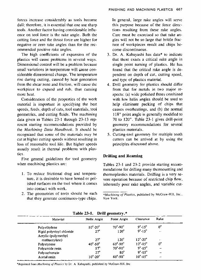
4. Drill geometry for plastics should differ from that for metals in two major re- spects: (a) wide polished flutes combined with low helix angles should be used to help eliminate packing of chips that causes overheatings, and (b) the normal 1 18" point angle is generally modified to 70 to 120". Table 23-1 gives drill-point geometry recommendations for several plastics materials.
5 . Cutting-tool geometry for multiple tooth cutters can be arrived at by using the principles discussed above.
Drilling and Reaming
Tables 23-1 and 23-2 provide starting recom- mendations for drilling many thermosetting and thermoplastics materials. Drilling is a very se- vere operation because of restricted chip flow, inherently poor rake angles, and variable cut-
*Machining of Plasrics, published by McCraw-Hi l l , Inc., New York .
Table 23-1. Drill geometry.* Material Helix Angle Point Angle Clearance Rake
Polyethylene 10"-20" 70"-90" 9"-15" 0" Rigid polyvinyl chloride 2 7" 120" 9"-15" -
methacrylate) 2 7" 120" 12"-20" - Polystyrene 40"-50" 6 0" -90" 12"-15" 0" Polyamide resin 17" 70"-90" 9"-15" - Polycarbonate 21" 80" 9"-15" - Acetal resin 10"-20" 60"-90" 10"-15" -
Acrylic (polymethyl
*Reprinted from Machining ofP!asrrcs by Dr A Kabayashi, published by McGraw-Hill. Inc

668 S
PI P
LAS
TICS
EN
GIN
EE
RIN
G H
AN
DB
OO
K
0
m
8 8 8 8 m
N
0
N
m
.-(
2 9
0
m
0
8 8 m
0
N
0
0 9
0
0
z ZZ
z
a
m 3
2.2 8 x
Eg
b
o
W
"3
0
5ss
2 9
0
m
0
8 8 8 m
0
W
0
W
0
0 9
m
0
8 d
0
0 9
c1 0
0 9
0
0
g ZZ
S
a
g2
I- g
2
'0 3
39 8
30
xE
g
w zz
m
3
9
0
v) 3
9
0
N 3
8 8 2
W
0
0 9
m
0
8 8 m
0
r4
0
0 9
0
0
N
$ 3 'CI
3
s
m
3
9
0
m
3
8 8 8 8 8 8 8 N 3
El Q)
0
d
0
c1 0
3
0
0
0
N
10 &I
H
03
0
8 8 2 8 l-
0
W
0
m
0
d
0
0 9
m
0
8 8 8 z r4
0
3
0
0
0
m 3
m
3
8 8 8 8 m 3
N 3
2
W 0
0 9
m
0
8 8 m
0
N
0
0
4
0
0
3 0
c1
m 3
9
0
v, 3
9
0
N
4
8 8 8 8 8 8 El m
0
m
0
m
0
Pi 0
0
v)
N
N

FINISHING AND MACHINING PLASTICS 669
ting speed across the cutting edge. Wide pol- ished flutes will help provide chip clearance, and the wide flutes also provide easy entrance for the cutting fluid. High clearance angles will help to prevent the drill flank from rubbing in the bottom of the hold. All tool surfaces in con- tact with the workpiece should be honed or pol- ished to reduce frictional heat. Table 23-1 gives the helix angle and drill point geometry.
Drilling of Thermoplastics. In view of the variety of materials and operations involved, the following discussion is of a general nature. It is followed by some special instructions for specific thermoplastics.
Standard horizontal or vertical drill presses, single, gang, or multiple, can be used for drill- ing thermoplastics. Also, drills are commer- cially available that are especially designed for plastics.
Drills having one or two wide and highly polished or chrome-plated flutes, narrow lands, and large helix angles are the most desirable, as they expel chips with minimum friction, and hence with minimum overheating and gum- ming.
Points should have an included angle of 60 to 90" and a lip clearance of 12 to 18". A sub- stantial clearance on the cutting edges makes for a smoother finish. Drill points must be sharpened frequently and carefully, with care to avoid loss of the desired point angles. Car- bide-tipped points will hold cutting edges long- est, may be used at high speeds, and in some applications do not have to be cooled by liquid.
The use of liquids as lubricants or cooling agents should be avoided if practicable, as it necessitates a subsequent cleaning of the arti- cles. In the drilling of most holes, an air blast will suffice to help clear chips and to prevent overheating, which would cause clogging.
The speeds used in drilling holes in thermo- plastics will depend upon the type of material and size and depth of the holes. In general, speeds will be decreased with an increase in the size of the hole, and increased with increasing hardness of the material.
Drilling equipment must be in good condi- tion for accurate holes to be obtained. Loose spindle bearings or bent or poorly sharpened
drills will give inaccurate results with any ma- terial. The speed should be the greatest that will not cause burning or gumming, and the feed should be slow and uniform, to produce a smooth hole of uniform diameter. Chips should be removed by frequently withdrawing the drill from the work to clear the hole. In deep holes, the application of cutting oil or other cooling agent will prevent sticking of the chips. Pres- sure should be relaxed near the termination of through holes, to prevent breakthrough. In deep holes, an intermittent relaxing of the drill pres- sure will reduce clogging and runoff.
Drilling can be expedited by specially de- signed drill jigs. It is also possible to automate machining operations via self-feed drills that are ganged up around a product and can simul- taneously drill $- to i-inch-diameter holes at the rate of four to five products per minute. The operator loads a shell into the machine, pushes the start button, and the units advance, drill, and retract.
CNC-programmed drilling machines auto- mate the drilling operation and provide ex- tremely fast movement of the table with the fix- tured part attached. Although the actual drilling speeds and feeds cannot be altered greatly be- cause of material properties, the time of move- ment between holes and other operations may be as high as 780 in./min., compared to stan- dard manual/power feed machines at 80 in./ min. The result is more uniform work and higher production because of machine capabil- ities and the elimination of operator fatigue.
Cellulose Acetate and Acetate Butyrate. Standard twist drills developed for wood or metal are frequently used on acetate or buty- rate, but the drills especially designed for plas- tics, mentioned above, are preferred.
Drilling with the conventional drills of the type used for metal requires much slower speeds and feeds to give a clean hole and to keep the material from gumming, and more frequent backing out of the drill to clear chips. The quality of work can best be controlled by air-operated feeds and mechanical feeding de- vices.
Reaming of holes drilled in acetate or buty- rate is not recommended. Where accurate di- mensions are required in thin sections, good re-

670 SPI PLASTICS ENGINEERING HANDBOOK
sults are obtained by drilling to within about 0.001 inch of size and then running a hardened polished rod through the hole to smooth it.
The most important factor is the efficient removal of chips by the drill during operation. Chips often tend to pack in the flutes and fuse together because of the frictional heat developed and its effect upon styrene, which is thermoplastic. To minimize this fusing, highly polished flutes with a slow helix are used. Gen- erous side relief also will help reduce friction, but the cutting speed and feed are the prime factors in drilling a clear, true hole.
The suggested drilling speed for styrene ranges from 75 to 150 ft/min. for high-speed steel drills.
The most satisfactory type of drills used have been high-speed steel with a thinned web and drill point angle of 90" for small holes, increas- ing the angle to 1 18 " for large holes. The major manufacturers of twist drills supply special drills for use with plastic parts.
For accurate work and to minimize breakage of drills, guide bushings should be used (see Fig. 23-3). The design and heat treatment of these bushings are the same as used for drilling ferrous and nonferrous metals. Ample chip clearance is necessary if a through hole is drilled. Some provision in the jig is, of course, essential to ensure proper location of the work.
The use of coolants is suggested. These
Polystyrene.
\
M Fig. 23-3. When drilling polystyrene, guide bushings should be used to ensure accuracy and to minimize breakage of drills. (Courtesy Monsunto)
coolants have been successfully applied by passing the drill through a felt wick wet with the coolant, a technique that minimizes clean- ing of the part.
Where a blind hole is drilled, a faster helix often facilitates chip removal.
Acrylics. Because of the transparency of acrylics, it usually is desirable that the inside of a drilled hole have a high finish. Hence the drilling of acrylics requires extra care, and may call for special drills.
Though standard metal-type twist drills are satisfactory for the average drilling job in acrylics, they have a tendency to grab in large or deep holes. Better results are obtained with a sharp drill having a flute angle of 17 to 18", an included lip angle of 70", and a lip clear- ance angle of 4 to 8" . The lands of the drill should be highly polished and about one-fourth the width of the heel. Special drills for acrylics are commercially available, and usually have a slow spiral with highly polished flutes. Out- standing results can be achieved with a jet drill, the point of which is cooled with a lubricant fed through a hole in the drill. Holes of large diameter can be cut with either hollow-end mills or fly cutters. It is important that tools for drilling acrylics be kept free of nicks and burrs. All types of tools can be used on standard ver- tical or horizontal presses.
Rates of feed can be determined only by ex- perience. The proper feed will result in smooth, continuous spiral chips or ribbons. The feed should be slowed as the depth of the cut in- creases.
In drilling deep holes in acrylics, a lubricant is needed to prevent clogging and possible burning or scamng of the wall of the hole. An air blast to cool the drill will be found benefi- cial in all cases.
Nylon can be drilled satisfactorily with conventional twist drills, but more rapidly with special drills, designed for plastics, and having deep flutes, highly polished to facilitate removal of chips. In some, the flute leads are much longer than in conventional drills.
Polycarbonate. Standard high-speed twist drills perform satisfactorily (Fig. 23-4). The drill life in polycarbonate is five to six times greater than in low carbon steel. For the even
Nylon.

FINISHING AND MACHINING PLASTICS 671
Included angle
Clearance angle
Included Cutting-lip
90" with coolant 60" without coolant
15"
Rake angle Depends on drill spiral. May be ground-to-zero or five negative for thin sheet drilling,
longer life and sharper cutting edges required for high-speed work, carbide-tipped drills are recommended. An added advantage of carbide- tipped drills is the absence of gumming, even without air or liquid coolants. There is no ten- dency for the drill to break out of the bottom of the piece or chip the edge of the hole, even when the drill is forced. Holes can be enlarged with larger drills without hogging or chipping.
Turning speeds for drilling will vary with the surface finish desired and the degree of induced surface strain acceptable. The best hole is ob- tained with surface speeds of 200 to 300 in. /min. for drills less than f inch in diameter and speeds of 350 to 450 in. /min. for drill from 4 to 5 inch in diameter, when machined dry. A cooling medium should be used with speeds of 500 to 700 in./min. for drills under inch in diameter, and 1500 to 1600 in./min. for drills B or inch in diameter. A feed rate of 0.001 to 0.0015 inch per revolution will give the best results.
No matter what type of drill is used, cutting edges must be kept sharp. Dull drills give poor surface finish and undersized holes. Burrs tend to heat up the work and induce machined-in stresses.
The use of a coolant is suggested to lower induced strain. Commonly used cooling media are: air, an air-water spray mist, or very light
1
I
machine oil. One should avoid using standard cutting oils as they are not compatible with polycarbonate resin.
Annealing of drilled parts lowers strains and ensures optimum part performance.
Acetal. Standard twist drills and special "plastic" drills are suitable.
Standard twist drills are normally supplied with drill point angles of 118" and lip-clear- ance angles of about 12". These drills work better on acetal if the included drill point angle is reduced to about 90", although the 118" an- gle can be used. The lip clearance angle should be maintained within a range of 10 to 15".
"Plastic" drills are furnished with included point angles of 60 and 90°, and with lip-clear- ance angles of 10 to 15". The cutting edges of these drills usually are flattened slightly t6 pro- vide zero or negative rake. They have extra- wide, highly polished flutes and a low helix an- gle to ease the removal of chips. For best per- formance with acetal, the cutting edges of the drill should be sharpened in the usual manner (not flattened) so that a normal positive rake is obtained. A 60" included angle is of some ad- vantage when drilling through thin sections (approximately $ inch thick), but the 90" point is better for thicker work.
During drilling, the work should be firmly supported and securely held. For deep holes,

672 SPI PLASTICS ENGINEERING HANDBOOK
the drill should be raised frequently during drilling-about every a inch of depth-to clear the drill and hole of chips. A jet of compressed air should be directed into the hole to disperse chips and cool the drill.
Polysulfone. Normal steel-working tools work well with polysulfone. A configuration of 12 to 15" clearance angle, 118" point angle, and 5" rake angle may be used for any drilling operation.
Small holes can be enlarged readily without chipping. When drilling completely through a piece of polysulfone, there is a tendency for the drill to break out of the bottom of the piece or chip the edge of the hole. This can be elimi- nated by backing up the piece and reducing the rate of feed.
PPO Resins. Standard high-speed steel twist drills with a rake angle of 5" and an in- cluded angle of 118" perform well. It is im- portant to use sharp drills to maintain the qual- ity of machined parts. Recommended drilling speed are shown in Table 23-3.
ABS may be drilled effectively be- cause of its hardness and rigidity. The most im- portant factor is the removal of chips by the drill. Chips will tend to pack in the flutes and, as a result of frictional heat, fuse together. To minimize fusion, highly polished flutes with a slow helix are recommended, with generous side relief, and the use of coolants. Cutting speeds and feed rates also influence the drilling of clear, true holes.
A standard drill press is adequate for ABS; however, the drill bit should be ground to scrape rather than cut. Customarily,high-speed, double-fluted twist drills are satiifactory , but
ABS.
Table 23-3. Recommended drilling speeds for unfilled and glass-reinforced PPO
resins. SPEED (IN./MIN.)
Diameter (in.) Unfilled PPO Glass-Reinforced PPO
f /B 150 700 !A 300 750 x 450 750 x 5 00 750 x 650 8 75 x 775 800
superior finish will result from bits having a point with a 90" included point angle, 300" he- lix angle, and wide polished flutes. Backing up the drilling surface is generally desirable, and is mandatory with thin stock.
A moderate feed rate of 0.001 to 0.005 inch per revolution will tend to avoid burring and overheating. A slow feed rate and consequent residence time may cause heat buildup and tool drift. A drill surface speed of 60 to 180 sfpm is recommended. Holes with a depth of up to five times diameter may be cooled with a jet of forced air; for deeper holes, cooling with water is recommended.
Single-fluted drills, with the required fric- tional characteristics for piloting and chip re- moval capacity, allow relatively good heat dis- sipation with surface speeds of 300 to 500 sfpm for small diameters, depth-to-diameter ratios of 25 : 1, and plunging feed rates.
Burnishing double-fluted, small twist drills with 118" point angles and 0.003 to 0.005 inch off center, allow 65 to 100 sfpm with feed rates of 0.010 to 0.055 inch per revolution.
Hole saws with a skip tooth blade can be mounted in the drill press to cut larger holes.
Reaming Thermoplastics. Even though drilled holes are easy to make, they occasion- ally lack the precision or finish required for op- timum performance and appearance. The so- lution is reaming, which like drilling, is a simple process requiring only conventional tools.
Fluted reamers provide both accuracy and good finish. Properly sharpened, they assure shearing of material from sidewalls rather than trouble-making dislocation. Standard high- speed steel units, straight or fluted, are usable without alteration of the cutting edge, chamfer, o r rake angles. The normal chamfer angle is 45"; the normal rake angle is 5".
The helically fluted reamer is preferred over the straight-flute type because it provides a smoother cut, finer finish, and can be used in both through and blind holes. The straight flute reamer is limited to through holes.
Although reaming can be done dry, the use of coolants will produce better finishes. Water is the preferred coolant, but light machine oils

FINISHING AND MACHINING PLASTICS 673
can be used. Standard cutting oils should be avoided.
Recommended conditions for reaming ther- moplastics and thermosets are shown in Table 23-4.
Drilling of Thermosetting Plastics. The fol- lowing table gives a general basis for selecting speeds of drills for conventionally molded ther- mosetting plastics:
Drill Size t-P'PM
1700 No. 1 I through No. 27 2500
3000 No. 42 and up 5000 ib inch 5000
No. I through No. 10
No. 28 through No. 41
4 inch 3000 & inch 2500 4 inch 1700 & inch 1300
inch 1000 600
inch 600 A and B 1700 C through 0 1300
7 . inch
P through Z 1000
To drill holes in molded articles or to remove flash or fins in molded holes, it is best to use standard high-speed steel drills with deep flutes. Nitrided high-speed drills do not require fre- quent sharpening, and will last a long time. Drill points should be ground to an included angle of 70 to 90°, and have a lip clearance or relief made by grinding the back away to & inch wide, which reduces friction between the drill and the work and gives clearance for the chips. Backing off the cutting lip (rake angle) prevents the grabbing that occurs with a drill with a nor- mal point, and will sometimes prevent chip- ping of the hole when the drill breaks through the under side of the work.
Most drilling is done without a lubricant, but a blast of air at the drill point will keep the drill and work cool, prolong the life of the point, and help clear away chips. Drill speeds should be from 100 to 150 fpm, or faster if proved by trial. Drills should be about 0.002 to 0.003 inch oversize. For drilling thin sections, the point of the drill can be ground with a sharper included angle to stop chipping around the hole.
Some manufacturers will make to order spe-
cial drills for use in long-run or automatic drill- ing operations. These drills are made on slow- twist blanks and tipped with tungsten carbide. This is about the most economical type of drill for phenolics if the production will warrant the cost, and the best for very deep holes.
In drilling deep holes, good results are ob- tained, however, with steel drills having spe- cially polished flutes and 0.0001 to 0.0002 inch of chromium plate.
For drilling through holes in canvas-filled materials, the drill may be specially ground. The end is ground like that of a wood drill. The outer edges of the drill are cut like circle-cut- ting tools, while the center acts as a pilot. Thus, at the breakthrough the cutting is done through a thin section supported on both sides by heav- ier areas, and the final chip is a disc with a hole.
Reducing the friction between the drill and the material by grinding the drill off-center (which results in a slightly larger hole) will often prolong the life of the drill.
Cast Phenolics. For small holes, drill speeds of about 2800 to 12,000 rpm are commonly used. Drills of a inch or more diameter should have large flutes, for efficient removal of ma- terial, and the cutting edges should be ground with a negative rake. For the drilling of small holes for self-tapping screws, the hole is usu- ally one drill size smaller than the screw.
Rapid production is obtained by a multiple drill assembly. Multiple drill heads are like- wise effective. Where neither is available, drilling with a jig can be made both fast and accurate.
Tapping and Threading
General tapping recommendations for thermo- plastics and thermosets are given in Table 23-5. Finish ground and polish flute taps are recommended because less frictional heat will be generated. It is recommended that oversized taps be used because of elastic recovery of plastics materials. Oversized taps are desig- nated:
H1: Basic-basic + 0.0005-in. H2: Basic + 0.0005 basic + 0.0010-in.

674 S
PI P
LAS
TICS
EN
GIN
EE
RIN
G H
AN
DB
OO
K
5 U
E
.- .- * -3 0
u
z z
z z
Lo
L
o
m
3
0
0
Lo
3
9
9
9
9
N
Lo
L
o
3
0
0
N
3
9
9
9
9
Lo m
2
0
0
0
* 9
9
9
9
0
N
3
0
0
W
0 9
9
9
9
W
W
m
N
0
0
0
0
9
9
9
9
W
m
PI 0
0
0
* 0 9
9
9
9
Nt--
Nt-3
N
r.-. r
4t
-e
EE
T:
EE
E E
EP
PE
E
m
v,
Lo 3
0
0
v) 3
9
9
9
9
N
Lo L
o
3
0
0
N 3
9
9
9
9
0
Lo
m
3
0
0
0
3
9
9
9
9
0
d
ri c.l
0
0
W
0 9
9
9
9
9
9
9
9
W
ca m
Pi
0
0
0
0
\o
m
ri 0
0
0
d
0 9
9
9
9
4
3
4
3 n

FINISHING AND MACHINING PLASTICS 675
Table 23-5. Tapping.* Speed HSS Tool
Material Hardness Condition (fpm) Material
Thermoplastics 3 1 R ~ Extruded, 50 M10, M7,
1 2 5 RM or cast to molded, M1
Thermosets SORM Extruded, 50 M10, M 7 to molded, M1
1 2 . 5 R ~ or filled
Reinforced plastics 55t Molded 25 M10, M7, Silica fiber- to M1
resin (Refrasil) reinforced phenolic 75
*Reprinted from Machining Data Handbuuk. tBarcol hardness.
H3: Basic + 0.0010 basic + 0.0015-in. H4: Basic + 0.0015 basic + 0,0020-in. H5: Basic + 0.0020 basic + 0.0025-in. H6: Basic + 0.0025 basic + 0.0030-in.
The amount of oversize depends on elastic re- covery properties of the material and sizes of holes. The number of flutes determines the chip space and the chip load per tooth; therefore, some compromise must be made. In general, the two-flute taps are preferred for holes that measure up to { inch.
Thermoplastics. Unless special accurate tap- ping machines with lead screws are available, it is unwise to attempt Class 2 or 3 fits. In any case, a higher percentage of rejects and higher costs may be expected, especially with nylon.
United States Standard (American Coarse Thread Series), Whitworth Standard (British Standard Series), and Acme are generally sat- isfactory. Sharp V-threads are to be avoided because the apex is easily broken. Coarse-pitch threads are preferred for their strength.
Bottom taps should be avoided whenever possible. If a bottom tap must be used, it should be used in a second operation done by hand, and only when a Class 2 or 3 fit is required. For maximum strength and dimensional stabil- ity, all tapped parts should be annealed to re- lieve the stresses set up by the tapping.
Before tapping, it is recommended that the
hole be drilled to such size as to permit not more than 75% of a full thread, to minimize difficulty in clearing the tap.
To obtain effective clearance of chips with a minimum of friction, large, highly polished flutes are recommended. Taps should nitrided or chrome-plated. All new taps should be stoned to remove burrs.
Taps for all thermoplastics should have max- imum back clearance. In most cases, the pitch diameter should be 0.002 inch oversize. For tapping nylon, 0.005 inch oversize is recom- mended, unless a tight fit is desired.
Designs and speeds for several thermoplas- tics are as follows:
Number of Cutting Speed Flutes (hm)
Cellulose acetate 2 o r 3 50 to 100
Methyl methacrylate 4" 35 to 75
Nylon 3 or 4" Polystyrene 3 or 4' 25 to 35
7 5 to 125
Grind back rake angle to about 2 " positive. Or use No. 2 flute spiral.
' Grind to zero rake.
The use of air or a lubricant is not essential in tapping, but it facilitates clearing the chips and permits faster tapping. The tap should be backed out before enough chips are formed to block the cooling agent.

676 SPI PLASTICS ENGINEERING HANDBOOK
In threading or tapping thermoplastics to fit a metal bolt or nut, allowance should be made for the difference in thermal expansion between the two materials. A slight increase over nor- mal metal clearances usually is ample; but if variations in service temperature are to be ex- treme, dimensional changes will be too great to be accommodated in this way, and threading should be avoided.
Instead of being tapped, thermoplastics may be threaded on conventional lathes or screw machines. On automatic and semiautomatic machines, with self-opening dies, chasers should be ground to zero rake, highly polished, and chromium-plated. For nylon, a conven- tional rake, as for mild steel, is recommended. In most cases, two passes should be made, and the work flooded with water containing a high percentage of mild soap or other cooling agent that will not attack the plastic. If a single-point tool is used in a lathe, the point should have a 2" side rake and a zero back rake (for nylon, a zero side rake and a 2" back rake). The best possible results will be given by diamond- pointed tools.
It is generally advisable to tap threads only in impact (modified) type styrene. As a general rule, National Coarse (NC) threads are preferred for the following reasons: greater strength, as more plastic area results due to the smaller minor diameter for the internal threads; and a slower helix, which results from the smaller number of threads per inch, making chip removal easier.
Spindle speeds approximately one-half of drilling speed are suggested for tappings, with the use of a coolant.
A three-flute tap is self-centering and offers easier chip removal than a four-flute type. Holes to be tapped should be slightly larger di- ameter than for metal in order to leave about 75% of a full thread. This will prevent the top of the thread form breaking or peeling off.
Polycarbonate. Standard steel working taps are recommended. Taps that produce threads with slightly rounded root diameters are pre- ferred, and the use of a light machine oil during tapping is recommended to overcome resis- tance and reduce tap wear.
Self-tapping screws of the Parker-Kalon B-F
Polystyrene.
National Screw-Type 25 thread cutting may be used with polycarbonate resin where envi- ronmental conditions permit. To ensure the best performance, it is important that the diameter of the hole be in proper relation to the diameter of the screw to be used. For example, the cor- rect diameter of the hole for a No. 8 X + inch screw is 0.147 inch, and the ideal penetration is 0.75 inch, or about four full threads on the screw. The wall thickness from the screw to an edge should be at least equal to the diameter of the screw.
The torque resistance of threads tapped in polycarbonate resin is high. A $-inch-diameter bolt of 13 threads per inch, penetrating a block of resin to a depth of & inch, requires 48 ft lb of torque to strip the threads.
ABS. Standard metal-working tools are used. Taps should have a slight negative rake, and should produce threads with the root di- ameters slightly rounded in order to avoid any possibility of notch-effect weakening of the part. Taps and dies for copper and brass may be used effectively. Lubricants should always be used, and turning speeds should be very slow.
Thermosetting Plastics. Phenolics may be tapped with standard taps. The most durable are commercial ground taps with rather short chamfer and with 0.0001 to 0.0002 inch of chromium plate. If it is required to hold Class 2 or Class 3 threads, the taps should be over- size by 0.002 to 0.003 inch. Holes should be chamfered to the maximum diameter of the thread. Here again is an instance where a planned mold design may help. Frequently a hole may be spotted or molded to a shallow depth, to be drilled and tapped to final depth later. In such cases, if the hole is to be tapped, the chamfer may be molded in at the same time as the hole, to eliminate one operation.
For long production runs, a high-speed ni- trided and chromium-plated tap, having three flutes rather than four, is recommended. Solid carbide taps will pay for themselves if used in a machine equipped with torque-control. A negative rake of about 5" on the front face of the land and ample clearance are necessary to ensure accurate cutting and to prevent binding

FINISHING AND MACHINING PLASTICS 677
and chipping during backing out. For tapping mineral-filled material, which tends to dull the tap very rapidly, sometimes a carbide tap can be used, provided that the work is clamped tightly under a torque-controlled tapping spin- dle so as to prevent breakage of the tap.
Flutes of taps can be opened by grinding, to make room for clearance of chips. Most tap- ping is done dry, but oils can be applied as lu- bricants. Paraffin wax sometimes is applied to the point of the tap to help to prevent heating, but air blasts on the tap, operated by the stroke of the tapping head, will help to clear the chips and cool the tap and the work. This minimizes overheating, prolongs the life of the tap, and promotes greater production per tap.
Peripheral speeds for tapping molded phe- nolics are from 50 to 80 fpm for taps up to inch diameter. Taps larger than this are im- practical in phenolics.
A blind hole should not be machine-tapped unless there is plenty of clearance at the bottom for the tap.
Cast Phenolics. Cast phenolics may be easily tapped on vertical or horizontal tapping ma- chines with standard taps. To provide strength, fairly coarse threads should be used. Tapped holes should be checked with plug gauges, as the abrasive action of the material causes wear. Standard machine screws can be used for as- sembly.
Cutting of threads of large diameter or coarse pitch, such as on bottle caps or jar covers ma- chined from solid material, is done on a thread- milling machine, with a small milling cutter of the proper shape.
Turning and Milling
Tables 23-6 and 23-7 give the starting recom- mendations for turning many thermosets and thermoplastics. Table 23-6 covers turning, sin- gle-point and box tools; Table 23-7 covers turning, cutoff and form tools. The definitions are as follows: (1) single-point turning: using a tool with one cutting edge; (2) box tool turn- ing: turning the end of a workpiece with one or more cutters mounted in a boxlike frame, pri- marily for finish cuts; (3) turning cutof sev-
ering the workpiece with a special lathe tool; and (4)form turning: using a tool with a special shape.
Chatter, with resulting problems in tool life, finish, and tolerance, can be encountered in turning operations due to workpiece flexibility. The low modulus of elasticity of plastics makes it desirable to support the work to prevent de- flection of stock away from the cutting tool due to cutting forces. Close chucking on short parts and follow rests on long parts are beneficial. Box tools are designed to support long turning operations, and should be used where possible. Water-soluble cutting fluids should be used, unless they react adversely with the work ma- terial, to reduce the surface temperature gen- erated at the shear zone and the tool-chip interface. To reduce frictional drag and tem- perature, tools should be honed or polished at work contact points.
Face Milling. Table 23-8 gives starting rec- ommendations for face milling plastic mate- rials. The fixtures used should provide ade- quate support for workpieces. Milling cutters usually have multiple cutting edges. In Table 23-8, feed is given in in. /per tooth, which must be converted to in./min of table travel. Too high a table feed will cause a rough surface; too low a feed travel will generate excessive heat that can cause melting, surface cracks due to high temperature, loss of dimensions, and poor surface finish. Use of mist-type water-sol- uble cutting fluids is recommended unless workpiece-cutting fluid compatibility problems are known to exist. To reduce frictional drag and temperature, tools should be honed or pol- ished where they contact the workpiece.
Face milling also can be accomplished by using a flycutter. The flycutter is held in a col- let or chuck in the milling machine and con- tains a special lathe cutting tool mounted at an angle of approximately 15" to the work sur- face. The flycutter rotates across the work and cuts over the entire workpiece as it advances. This results in a smooth surface over the entire work area, as opposed to the several passes re- quired by the face of a smaller end mill.
Tables 23-9 and 23-10 give starting recom- mendations for end milling-slotting and end

67
8
SPI PLA
STIC
S E
NG
INE
ER
ING
HA
ND
BO
OK
$ 0 3
8 0
3 2 d P $ 2
8 0
v)
m
$ N
0
v)
4
0
N
Lj
N
0
8 0
0
2 v) d P $ N
0
8 0
0
x 0
m
v)
PI
8
N
cj
v) 3
8 0
0
2 d
P N E
v) - 9 0 0
v)
2 v) N
0
v)
0 1
N
cj
v)
0
8 0
0
v)
$ P 2 v)
0
0 9
0
0
0
m
B v)
N
8
N
Lj
v) 3
8 0
0
0
v)
z P N"
E
2
8 0
0
B 0 m
0
v)
0 1
TJ
0)
s s
NN
66
-0
0
-
88
00
0
0
F-v
)
$e \D
b
PP
N
N
- E
E
NW
00
00
99
00
0
0
00
o
w
bN
73
Loo
Nv
)
00
91 z v
) 0
8 0
0
0
v)
2 P 2 v)
0
8 0
0
2 0
m
m
N
8 z 0 3
8 0
0
0
N
2 P $ m
0
0 9
0
2 li, b
0
v)
0
N 6
N
0
8 0
0
B VI
rn
P 2 - 0 8 0
0
2 v) 3 m
N
8
N 6
N
CI
8 0
0
0
N
e F-
P 2 N
4
2 0
0 2
0
0
v)
z m
0
NN
66
mr
4
0-
8
8
00
0
0
82
Ad
00
o
m
3
PP
N
- N"
BE
WN
0
-
88
0
00
0
0
NW
00
60
2-
mo
Nv)
0-
00
N 6
v)
0
0 9
0
0
v) - 0 m
b
P 2 v)
0
0 9
0
0
0
0
0
v)
m
N
0 9
N 6
2
9
0
0
0
E: 0 0
P
P N* E
N 3
2 0
10
s 10 W
0
10 3
6
z a s z v)
0
8 0
0
0
c;' 2: b
P $ v)
0
8 0
0 2
&
v)
r-
VI N
8

FINIS
HIN
G A
ND
MA
CH
ININ
G P
LAS
TICS
6
0
r4 9
0
VI
0
9
,-
0
VI
7
0
0 7
.-(
0
9
3
0 9
m
0 9
m
0 9
3
0
9
3
0 9
3 0 9
N
0
9
N
0 9
rn 0
9
m
0
9
m
0
9
00
N
rn
w
gv
,
Gd
E
1a
m
2r-
"I
?
CI
0 9
N
0 9
m 0 9
rn 0
9
m
0 9
N
3
VI
0
s v,
0
0 9
v1
0
0
9
3
0 9
3
0 9
N
0
9
CI
0 9
N
0 9
N
0
9
N
0
9
N
0 9
N 0
4
N
0
9
m 0
9
rn 0 9
m
0 9
N
0 9
PI
0
4
N
0 9
CI
0
4
N
0 9
m 0 9
m
0
9
m 0 9 3
a
a
p%
Pi2
N
Ex
6
N
0 9
N
0
9
N
0 9
N
0 9
N
0 9
m 0
9
rn 0 9
m 0 9
00
dv
1
020
'I? 3 3
23
OB,
v,
N
3
0 9 - 2 4
N
0 9
CI 0 9
N
0 9
m
0 9
m
0 9

680 SPI PLASTICS ENGINEERING HANDBOOK
Table 23-8. Face milling.* High-speed Steel Tool Carbide Tool
Depth Feed Tool Feed, Tool of Cut,? Speed (in./ Ma- Speed (in./ Ma-
Material Hardness Condition (in.) (fpm) tooth) terial (fpm) tooth) terial
Thermoplastics 3 1 R ~ to Extruded, 0.150 500-750 0.016 M2, M7 1300-1500 0.020 C-2 1 2 5 R ~ molded, 0.060 750-1000 0.004 M2, M7 1500-2000 0.005 C-2
or cast
Thermosets 5 0 R ~ to Extruded, 0.150 200-300 0.015 M2, M7 1300-1500 0.015 C-2 1 2 5 R ~ molded, 0.060 400-500 0.005 M2, M7 1500-2000 0.005 C-2
or cast Reinforced plastics 55 $ to - - - - - - -
Silica fiber- 75 Molded 0.060 - - - 1300 0.009 C-2 reinforced phenolic resin (Refrasil)
*Reprinted from Machining Data Handbook. ?Depth of cut measured parallel to axis of cutter. fBarcol hardness.
milling-peripheral. End milling generally is accomplished with a tool having cutting edges on its cylindrical surfaces as well as on its end. In end milling-peripheral, the peripheral cut- ting edges on the cylindrical surface are used;
whereas in end milling-slotting, both end and peripheral cutting edges remove metal. Face milling, in contrast, applies to milling a surface perpendicular to the axis of the cutter.
Specifically, end mills are used on thermo-
Table 23-9. End milling-slotting.*
Feed-inches per Tooth HSs Tool Depth* Material
Hardness' of cut Speed Width of Slot-Inches except as Material BHN Condition (in.) (fpm) y2 '/4 1 to 2 noted
Thermoplastics 3 1 R ~
to
1 2 5 R ~
Thermosets 5 0 R ~
to
1 2 5 R ~
Silica fiber- 5 5 reinforced phenolic resin (Refrasil) to
75 t
Extruded,
molded,
or cast
Cast,
molded,
or tilled
Molded
270
450 .250 to .002 .003 .005 .008 M2,M7
300
500 .OS0 to .001 .002 .004 .006 M2,M7
125
180 .250 to .002 .003 .005 .008 M2, M7
140
200 .OS0 to .001 .002 .004 .006 M2, M7
.250 760 - - .004 .005 C-2 Carbide
.OS0 850 - - .003 .004 C-2 Carbide
*Reprinted from Muchinkg Dora Hundbook. tBarcol hardness.


682 SPI PLASTICS ENGINEERING HANDBOOK
plastics to finish off the surface when a part has been degated from the sprue. The end mill may be placed in a drill press and used as in a drill- ing operation. A jig should be used for safe practice and quality work.
In addition, a side mill or a reamer may be used to remove a heavy parting line from a molded thermoplastic piece. The removal of unsightly seams due to clamping and cement- ing may be done in the same manner.
The best results are obtained in milling when using two-flute end mills for greater chip clear- ance and less work contact, to avoid burning and discoloration of material.
Finally, milling may be used to shape or fab- ricate a plastic rod or bar.
Thermoplastics. For turning and milling of thermoplastics, four cutting materials fill most needs: high-speed steel, high-speed steel chrome-plated, tungsten carbide, and diamond. They may be rated as shown in the tabulation, where the range is arbitrary from 1 (best) to 10 (worst).
Tools of standard carbon steel or high-speed steel may be used for short runs if their cutting edges are kept very sharp and their faces highly polished. However, carbide-tipped or diamond tools are almost essential for long runs because they hold a keener edge for a longer time. Such tools make possible a highly polished surface finish. To minimize surface friction at the max- imum cutting speed, the side and front clear- ances of the tools should be somewhat greater than those of standard turning tools. Both steel and diamond end-mills should have the same cutting angles and rakes as carbide tools.
The cutting edges of all tools should be kept honed very keen. Standard carbide-tipped tools are very satisfactory except that clearance an- gles should be ground to from 7 to 12". The top surface should be lapped to a bright finish. A soft iron wheel impregnated with a fine grit of powdered diamond often is used. Diamond tools are usually designed like the standard car- bide tools described above, except that for turning nylon a sharp-pointed tool with a 20" positive rake is used.
A circular tool is economical in quantity pro- duction wherever it can be used.
With most thermoplastics, surface speeds may run as high as 600 fpm with feeds of from 0.002 to 0.005 inch. The speed and feed must be determined largely by the finish desired and the kind of tool used. It is difficult to make fine finish cuts on nylon except with a carbide- or diamond-tipped tool.
Good results are obtained without lubricat- ing the cutting and turning tools if feed pres- sure is relaxed often enough to avoid overheat- ing. On turret lathes, good lubrication is obtained, if necessary, by flowing a mixture of equal parts of soluble oil and water, or a soap solution, over the tools.
Milling operations must be held to very light cuts, not over 0.010 inch at normal feeds. End milling with a centercutting tool may be per- formed on an ordinary drill press, as long as the work is rigidly supported and the feed is steady and slow. Feeds may be increased with the aid of a suitable cooling agent. It is entirely practicable to use hand feed, but for the best finishes, power feed is advisable.
Vibration of the machine will cause a poor finish.
Tool Design. In turning polycarbonate parts, a very sharp tool of high-speed steel or carbide is best suited for clean smooth cuts. Suggested tool angles for this particular use are as fol- lows: back rake-5 to 10"; side rake-15"; side clearance- 15 " ; and front clearance-5 to 10". Polycarbonate parts can be cut without coolant at turning speeds of 1500 to 2500 in./min. A coolant, preferably water, should be used with higher speeds to minimize strains and reduce surface galling.
Cutting depths range from 1 to 100 mils. When the finish or dimensions are critical, the depth should not exceed 15 mils. The cross- feed rate, which is dependent on the cutting depth, varies from 1 to 3 mils per revolution.
The finest surfaces are obtained by using a round-tip cutter, a high turning speed, a shal- low cut, and a low cross-feed rate. Radii of 15 to 30 mils are suggested for round-tip cutters.
In turning polystyrene parts, tools should be ground to produce a straight nontwisting ribbon cut. The tool should have a slight negative rake (about 2 " ) , a clearance angle of from 10 to 15",

FINISHING AND MACHINING PLASTICS 683
ii I Tool Location
'4 bc/ Side
Front 4 1 d d- Fig. 23-5. General-purpose tool recommendations for ABS. (Courtesy GE Plastics)
and a side rake of about 10". By setting the cutting edge at 1 to 2" above the center of the work and not directly at the center, the ten- dency of the work to climb is minimized. In all turning and most especially the facing of large diameters, coolants are essential.
Pieces should be run at speeds at which there is no vibration. This can only be determined by trial and error. Speeds up to 1300 rpm, if the piece is held rigidly, are practicable for light cuts. Either a liquid or an air blast coolant will do.
For inside turning or boring, if the diameter is large, comparable speeds may be used; but in feeding coolant to small hole operations, surface speeds may have to be decreased. To avoid crazing of the surface, the surface heat should never be raised above 175°F. Accord- ingly, the tools must be kept sharp and cool.
In turning ABS, high-speed steel tools are satisfactory, but for longer service life, car- bide-tipped tools are recommended. A general- purpose tool design is shown in Fig. 23-5, with recommended angles as follows: (a) positive rake angle-0 to 5" (less frictional heat buildup occurs using a positive rake because work is cut rather than scraped); (b) front or end clear- ance angle-10 to 15" (this angle must be great enough to prevent the tool heel from contacting the work); (c) nose or end radius-& to & inch (in general, the greater the nose radius, the bet- ter the surface finish at a given speed or feed rate; cutting may be reduced, however, and
heat buildup increased as the radius increases); (d) side clearance angle-10 to 15" (this di- mension is not critical, except that a clearance must be allowed to minimize frictional heat buildup); (e) side rake angle-0 to 15" (to aid in removal of curls); and (f) tool angle in re- lation to work-approximately 2" above cen- terline of work (this will minimize tendency of work to climb or chatter).
Thermosetting Plastics. Molded phenolics and ureas should not be machined unless it is impossible to form the desired shape by mold- ing. Because machining of molded articles de- stroys their lustrous surface, machining is re- stricted to articles made for utility rather than appearance. Only with a few special materials can the machined surface be satisfactorily pol- ished.
Fillers cause difficulties in machining in the order (1) wood flour (least), (2) fabric, (3) cot- ton, (4) mineral, and (5) glass (most).
One of the greatest problems in machining phenolics is their inability to dissipate heat. Another is their tendency to chip.
The procedures for machining phenolics are similar to those for machining brass. The cut- ting action is more a scraping than a peeling. The speed in feet per minute is high and com- pares with the speeds for brass. The principal difference is in the abrasive action; phenolics dull the regular steel tool very quickly.
Most turning and boring of the phenolics on

684 SPI PLASTICS ENGINEERING HANDBOOK
a lathe is done dry. A jet of air at the point of the cutting tool reduces the rate at which the tool is dulled, and clears away the chips.
Cast Phenolics. Regular machine-shop equipment is used in producing articles from cast phenolics. In quantity production on screw machines, operations similar to those applied to metal, such as drilling, turning, threading, tapping, and milling, require only differently ground tools, and ranges of feed and speeds ad- justed to the requirements of the materials.
There are a few hard-and-fast rules govern- ing the machining of cast phenolics, but in gen- eral high speeds and light cuts are preferable. Nearly all the work is done dry. Nonalkaline cooling agents may be employed, but rarely are required. In producing articles on an automatic screw machine, where the taper of cast phe- nolic rod may hamper the feeding of it, the rod may first be centerless-ground accurately to uniform diameter.
Turning tools are sharpened very much as for brass. There should be plenty of clearance, 10 to 20", and a slightly negative or zero rake is desirable. The tool should be set 1 to 2", and a slightly negative or zero rake is desirable. The tool should be set 1 to 2" above the center of the material. Cutting edges should be in con- dition to produce long ribbon shavings or chips. Honed tools produce the smoothest cuts. Dia- mond, carbide, or high-speed steel may be used to get the longest runs without resharpening or resetting.
For maximum efficiency and best working conditions, dust and shavings should be re- moved by a blower.
Spindle speeds in turning operations range from 450 to 6000 rpm, depending on the spe- cific work being done and the diameter of the material, and should be regulated to give a sur- face speed of about 600 fpm.
Sawing
Tables 23-11 and 23-12 give general recom- mendations for the power band sawing of plas- tics. Band sawing is recommended because it is more versatile for making irregular or curve contours as well as straight cuts. Best results
are obtained with a skip tooth or buttress-type tooth having zero front rake and a raker set to the teeth.
The greatest single problem in the sawing of most plastics is the dissipation of heat. Because many plastics, especially thermoplastics, have very low softening temperatures, and all plas- tics are poor thermal conductors, a cooling agent (liquid or compressed air) is needed, un- less the cut is very short, such as in the removal of a gate.
Round saws should be hollow-ground, with burrs from sharpening removed by stoning, and band and jig saws should have enough set to give adequate clearance to the back of the blade. This set should be greater than is usual for cutting steel. It is always best to relieve the feed pressure near the end of a cut, to avoid chipping.
The proper rate of feed is important, and, because most sawing operations are hand-fed, it can be learned only through experience. At- tempts to force the feed will result in heating of the blade, gumming of the material, loading of the saw teeth, and an excessively rough cut. Before the next cut is made, the saw must be cleaned. Chromium plating of the blade re- duces friction and tends to give better cuts.
Above all, the saw, whether band or circu- lar, must be kept sharp. Frequent sharpening of circular saws pays for itself. Dull bandsaws should be replaced.
Circular saws are usually from $ to f inch thick. The width of bandsaws is usually to 1 inch.
Both thermoplastic and thermosetting resins can be sawed also by use of cutoff machines having abrasive wheels. This equipment is used for cutting rods, tubes, and so forth, into lengths, for slicing profiled bars of cast phe- nolics, and for removing large gates. Narrow- faced wheels are used (0.02 to 0.125 inch), usually containing a silicon carbide abrasive in the range of No. 36 to No. 50. With an appro- priate wheel properly used, clean cuts can be made. If necessary, water is used to prevent overheating.
Thermoplastics. As already indicated, the sawing of thermoplastics will require a wide

FINISHING AND MACHINING PLASTICS 685
Table 23-11. Power band sawing, vertical, high-speed steel blades.* Material Pitch Band
Hardness Thickness Tooth (teeth Speed Material BHN Condition (in.) Form? per in.) ( fpm)
Thermoplastics Polyethylene Polypropylene Fluorocarbons Butyrates High-impact styrene Acryloni trile-bu tadiene-
Modified acrylic Nylon Acetals Polycarbonates
styrene
Acrylics
Polystyrenes, medium and low impact
Fluorocarbons
Cellulose acetate
Nylon
Thermosetting Plastics
formaldehyde Melamine-
Phenolics
Urea-formaldehyde
Extruded, molded, or cast
Extruded molded, or cast
Molded
Extruded, molded, or cast
Molded
extruded
Extruded, m o 1 de d , or cast
Molded
or
Molded
Unfilled, molded
Cast, molded, laminated- asbestos or fabric filler Cast or molded, no filler
Cast, molded or laminated with glass or mineral filler
Molded
<% Y* -1
<% Y* -1
<:: z -1
<% %-I
<% z -1
<% z -1
<% z -1
<% z -1
1-3 >3
1-3 > 3
1-3 > 3
1-3 > 3
1-3 >3
1-3 > 3
1-3 > 3
1-3 > 3
<% z -1
<% x -1
<% z -1
<x
1-3 >3
1-3 >3
1-3 >3
-1 1-3 >3
<% z -1 1-3
P P B B P P P B P P B B P P B B P P B B P P B B P P B B P P B B
P P B B P P B B P P B B P P P -
P P B B
10-14 6 3 3
10-14 8 6 3
10-14 6 3 3
10-14 6 3 3
8-10 6 3 3
8-1 0 6 3 3
10-14 6 3 3
10-14 6 3 3
10-14 8 3 3
10-14 6 3 3
10-14 6 3 3
10-18 8 6 -
10-14 6 3 3
4000$ 3000 $ 2500$ 1500$ 2300% 2000 $ 1500$ 1000 $
3000$ 2500$ 2000$ 1500 $ 4000$ 3000$ 2500$ 1500 $ 2300$ 2000$ 1500$ 1000$ 2300$ 2000 $ 1500 $ 1000$ 4000$ 3000$ 2500$ 1500$ 3000$ 2500$ 2000$ 1500$
5500$ SOOO$ 4000$ 3000 $ S S O O $ 5000$ 40001: 3000 $
5500$ 5000$ 4000$ 3000$
75 I 50 $ 50$
5000$ 4000$ 35003: 2200f
-
> 3 *Reprinted from Marhinirig Dura Hurrdbook. tP-Precision; C-Claw; B-Buttress. $Recommended speed for high carbon blades.

686 SPI PLASTICS ENGINEERING HANDBOOK
Table 23-12. Power band sawing, high carbon saw blads.* Pitch, teeth/in.
Minimum thickness of material, in.
Material Hardness Condition
Speed under 1 /2 over (fpm)
1 !4 and
74 and yl-
Thermoplastics Cellulose acetate 4 9 R ~ to Molded
Acrylics 8 0 R ~ to Extruded, 1 1 2 R ~
1 0 3 R ~ molded, or cast
Nylon 7 9 R ~ to Molded
Polystyrenes 7 0 R ~ to Molded or 1 0 0 R ~
9 5 R ~ extruded
10 6-10 3-6 3000
14 6-10 3-6 3000
14 4-10 3-4 2500
10 4-6 3-4 2000
Thermosets Melamine- 1 1 4 R ~ to
formaldehyde 1 1 9 R ~ Phenolics 5 0 R ~ to
9 3 R ~
1 0 0 R ~ to 105 RM
1 0 8 R ~ to 1 1 5 R ~
Unfilled molded 14 6-10 3 4 4500
Cast, molded lam- 14 6-10 3-6 4500 inated asbestos or fabric filler Cast or molded, 14 6-10 3-6 4500 no filler Cast, molded or 14-18 8-10 6-8 2000 laminated with
~~
glass fiber or graphitized cloth
Urea-formaldehyde 94 RE Molded 14 6-10 3-6 4500
*Reprinted from Machining Data Hatidbook, Research Associates Inc.
range of conditions, depending upon the type of resin involved. To illustrate, the following are recommendations for sawing styrene and for sawing polycarbonate, one of the so-called en- gineering plastics with greater toughness and heat resistance.
Polystyrene. Of the three types of sawing operations possible on styrene, namely circular jig or band sawing, the most preferable tech- nique is that of band sawing. This method lends itself most readily to sawing styrene since the heat build-up can be most easily dissipated.
Band sawing: The use of coolant (usually water) usually is advisable here. Nevertheless, it has been found that for styrene sections from g inch up, it is possible to increase the cutting efficiency and reduce the extent of lubrication by using a slup-tooth band, four to six teeth per inch, instead of the usual metal cutting band.
1
No coolant is required for ;-inch thicknesses of styrene. Metal cutting band saws can be em- ployed for cuts in sections of thickness smaller than inch. Ample coolant should be used for the latter; otherwise, the band will be seized by gumming and cause chipping at the cut. The operating speeds for band sawing styrene should be from 465 to 550 fpm.
In sawing thick sections of styrene (4-5 inches) it is desirable to use a wide band slot to permit clearing of waste and also to remove the slot disc. A helpful device in sawing thick sec- tions is to support the work on two wooden cleats which straddle the blade so that the spec- imen is held about : inch from the base of the saw. For thick pieces, operating speeds of 1100 rpm and a 36-inch band saw are recommended.
Circular sawing: It is advantageous to use a hollow ground saw for this purpose, although this is not always necessary if all the other pre-

FINISHING AND MACHINING PLASTICS 687
cautions are taken. Blade thicknesses may vary from 0.040 inch for sections up to inch, in- creasing to & inch for heavier pieces. For gen- eral work a &-inch blade is a good compro- mise. Saw diameters may be from 4 to 10 inches. Smaller saws derive their advantages from the fact that they have lower peripheral speeds at any given spindle speed. Conse- quently, they have less tendency to heat them- selves and the work. The thickness of the work determines, for the most part, the number of teeth per inch. Another consideration is the di- ameter of the saw. For a 4-inch blade, a good compromise is from 8 to 10 teeth per inch; for thicker work sections and larger-diameter blades, the number of teeth may increase to 15 per inch.
The use of coolant is almost always recom- mended for this operation. The saw should be flooded with coolant directly above and at the point of operation. Customary operating speeds are from 1800-2000 rpm. Nevertheless, if an uninterrupted flow of coolant is fed to the saw, speeds as high as 3450 rpm can be reached without damaging the material or the tool. Only when small cuts (of 2 inches or less) are taken can coolant be dispensed with in circular saw operations using normal-type blades. In so doing, the feed must be unforced. A helpful device in circular sawing is to have the clear- ance between the blade and the saw table as narrow as possible to prevent the material from pulling into the gap.
Jig sawing: This operation is not a rec- ommended one for styrene. The jig saw blade, because of its reciprocal action, cannot handle the liberal quantity of coolant required and con- sequently tends to splash it up toward the op- erator on the upward stroke of the blade. It is generally preferable to rout holes out rather than resort to jig sawing. For sharp-comered holes, band filing without coolant is recommended, provided that the feed is light. In those in- stances where it is absolutely necessary to use a jig saw, standard blades may be used at a speed of about 875 cycles per minute.
Polycarbonate. Parts molded of polycarbon- ate can be cut with common band and circular saws as well as with hand or power hack .saws. Special blades rarely are required. Blade speeds and cutting rates are not so critical as with other
thermoplastics because of the high heat resis- tance of polycarbonate.
Special attention to blades and cutting rates is needed only when sawing is the final or only machining operation, or when very thick sec- tions are involved. For material 1 inch or more thick, blade and feed speeds should be care- fully chosen, just as they would be for soft met- als. Band saw blades with 10 to 18 teeth per inch are satisfactory. When the blades have a set, the preferred range is 20 to 30 mils. Tooth spacing for circular saw blades ranges from large (for cutting thick sections) to very small (for cutting thin sections). The best procedure is to use the smallest spacing that gives satis- factory performance.
The recommended clearance angle for cir- cular saw teeth is between 20 and 30". The rake angle should be 15".
High-speed steel or carbide-tipped circular saws with alternate beveled and straight milled teeth are preferred. The use of designs that eliminate the possibility of the blade body rub- bing the stock during sawing improves the re- sults, particularly when working with thick sections.
The table gives recommended sawing con- ditions for polycarbonate.
Thermosetting Plastics. The sawing of these plastics is confined to band saws (solid or in- serted-segment), carbide circular saws, and ab- rasive cutoff discs.
Nearly all of these plastics are extremely ab- rasive. Some of them, notably the glass-filled alkyds, with dull a circular saw of high-speed steel in a cut of a few inches in $inch material. In production runs of this material, it is prob- ably best to use an abrasive cutoff disc, 0.040 to & inch thick, 6 to 20 inches in diameter, run at from 3500 to 6000 rpm.
Phenolics, ureas, and melamines usually are cut by band saws, which have the advantage of dissipating the heat.
An air jet should be used at the point of con- tact, and a suction hose to remove the dust.
Piercing, Trimming, and Routing
Thermoplastics. Small holes may be punched through thin sheets of thermoplastics on stan-

688 SPI PLASTICS ENGINEERING HANDBOOK
dard hand-operated arbor presses, but an ordi- nary punch press or shearing machine generally is used. Thin sheets may be processed cold, but thicker sheets should be heated. For acrylics, about 185°F will be required for the heavier sections, but the other materials should not be heated above about 120"F, in order to prevent damaging the surface and finish.
It is common practice to remove ring gates from injection-molded articles by shearing, even to the extent of making multiple-cavity punching dies for multiple-cavity moldings. It is important that the punch and die fit closely, to avoid producing ragged edges.
Blanking or shaving dies frequently are used for removing parting lines and flash lines. The punch and die sometimes are heated to leave the best possible finish. Routing and shaping are done on standard woodworking equipment. For fine cuts at high speed, single- or multiple- bladed fly cutters should be used.
Routing is a grooving or milling operation. It is done by means of small-diameter cutters having three or more teeth of the desired profile and mounted on vertical spindles that project above a metal tabletop. These cutters revolve at high speeds (e.g., 12,600 rpm) so as to pro- duce smooth cuts.
The work is held in a special fixture equip- ment with a metal master guideplate that is kept in contact with a metal collar on the table, di- rectly below the cutter. The fixture is moved by hand.
For bringing rough-sawed articles of flat stock to size and shape, edge-molders are used, of the type used for finishing articles of wood. A cutter of the desired profile is mounted on a verticle spindle, which revolves at 7000 to 10,000 rpm, depending on the size of the cutter and the amount of stock to be removed. The work is held in a fixture equipped with a metal master guideplate, which is kept in contact with a collar on the spindle below the cutter. The fixture is moved by hand. Fixtures of semi- automatic type have been developed to accom- plish this same result; the operator loads and unloads the fixtures as they advance to and from the cutters. The cut is made rapidly to prevent burning the material.
Thermosetting Plastics. If the quantities are sufficiently large to warrant the cost of piercing tools, they provide the best method for remov- ing flash from holes. A simple pad die with stripper plate may be made to pierce all holes and trim the outside shape of an article, at the rate of about 700 per hour. Small articles with several holes may be pierced in a dial press at the rate of about 1200 per hour. The piercing punches for removal of flash should be round- nosed and should have two or three helical grooves around the working end. These grooves should pass by the flash line in the hole, to rake the flash out of the hole. If the flash is on the surface of the article, it should be punched into the hole rather than out of it in order to prevent chipping.
Although thin sheets (i to 4 inch) of cast phenolic may be blanked with a steel-rule die, this is not recommended because of the diffi- culty in obtaining accurate cuts. Blanks are bet- ter and more economically obtained by casting a bar of the desired profile and slicing or cut- ting it with standard slicing equipment or ab- rasive cutoff equipment.
Blanking and Die-Cutting
Many thermoplastics sheets are thermoformed into end products such as luggage, housings, toys, trays, and so on. Most of these products are easily trimmed or punched with hardened steel dies.
Other types of trimming operations may in- clude the use of steel rules, punch dies, clicker dies, and hi-dies, depending on the gauge of the material. Punch presses, luck presses, and clicker or dinking machines are used in actuat- ing the different die-cutting methods.
Dies should be kept as sharp as possible. If they are not kept sharp, ragged or burred edges will result, possibly allowing cracks to propa- gate when the stock is under stress. Dies must also be kept free of grease and oils, some of which may create stress crazing or craclung in various plastics.
Many light-gauge plastics sheets may be trimmed with dies made of steel rules formed to the desired shape and placed in a wooden or

FINISHING AND MACHINING PLASTICS 689
metal frame. Steel rule generally is used to trim shallow drawn parts, but it can be built up eco- nomically into dies for cutting parts with draws more than 2 inches deep. Backup surfaces in many cases (e.g., for the styrene sheets) may be hard rubber or wood blocks oriented to use the end grains.
Heavier-gauge sheet may require stronger dies. Tool steel up to inch thick can be bent or forged to shape to make clicker dies. The hi- die is also suitable for heavy-gauge material and long runs. Parts with draws as deep as 7 inches may be trimmed without building up these dies.
Counterboring and Spotfacing
Counterboring involves the removal of material to enlarge a hole for part of its depth with a rotary, pilot-guided, end cutting tool having two or more cutting lips and usually having straight or helical flutes for the passage of chips and the admission of a cutting fluid.
In spotfacing, one uses a rotary, hole-pi- loted, end facing tool to produce a flat surface normal to the axis of rotation of the tool on or slightly below the workpiece surface.
Recommendations for counterboring or spot- facing plastics are indicated in Table 23-13.
Laser Machining
A technique that has gained importance in the machining of plastics is the use of lasers, par- ticularly the carbon dioxide laser. The carbon dioxide laser emits radiation at a wavelength of 10.6 microns, which is in the infrared region and is strongly absorbed by most plastics. In essence, the laser concentrates the invisible in- frared beam through focusing lenses to create a point in space with tremendous power density. If a workpiece is held stationary under the laser, it will drill a hole; if the piece is moved, it slits the material. The induced heat is so intense and the action takes place so quickly, that little heating of adjacent areas takes place.
Laser machining has been used for cutting and drilling such plastics as acrylic, polyeth- ylene film, polystyrene foam, acetal, and ny-
lon. Most plastics can be machined with the technique (epoxies and phenolics do not per- form well and vinyl also has problems).
Jigs, Fixtures, and Automatic Feeding Devices
The primary purpose of jigs and fixtures is to facilitate machining, in order to reduce manu- facturing costs and to make practicable various operations that cannot be performed by hand. With their aid it is possible to produce more pieces per hour, to use less skilled labor, to im- prove the accuracy of dimensions, and to re- duce the fitting necessary in assembling.
It generally is agreed that a fixture is a device that holds the article while the cutting tool is performing the work, whereas a jig is a device that not only holds the object but also incor- porates special arrangements for guiding the tool to the proper position. It would follow, therefore, that jigs are used principally for drilling, boring, and so on, whereas fixtures are used in milling and grinding. Regardless of the nomenclature, the most important feature of any jig or fixture is its ability to perform the work for which it was made.
Simplicity of design makes for low cost, long life, and inexpensive maintenance. With this in mind, the following rules may be used as a guide to the proper design of jigs and fixtures:
1.
2.
3.
4.
5.
First, it should be shown on the basis of cost studies, that the cost of designing and making a proposed tool will be less than the gross savings that its use will yield. All clamping devices should be quick- acting, easily accessible, and so placed as to give maximum resistance to the di- rection of the force of the cutting tool. The clamping pressure must not crack or distort the article of plastic. Locating points should be visible to the operator when positioning the article, in order to minimize loading time. All bearings should be of the sealed type, for protection against the highly abrasive plastic chips and dust.

690 SPI P
LAS
TICS
EN
GIN
EE
RIN
G H
AN
DB
OO
K
v)
ri
m
Nd
V
J 8
2
-4
-
0
0
d
0
8g
9
9
99
9
9
9
8 =
E:
-
0
9
99
9
9
99
9
9
9
2s
2
8
0
9
99
9
9
99
9
9
9
9
90
v)
v,
v)
rn
dm
d
o
0
00
0
4
-m
d
m
dm
d
m
0
00
0
0
v)
v)
mm
m
m
mm
m
ri
m
0
0
00
0
0
00
0
v)
ri
0
9
99
9
9
99
9
9
9
mr
i
ma
r
-\
o
P-
N
m
00
0
0
00
0
0
0
N
0 9
99
9
9
99
9
9
9
0"
s
00
0
9
99
9
9
99
9
9
9
85
1
0
9
99
9
9
99
9
9
9
mr
i
m
N
mr
i
me
0
00
0
0
v)
v,
VJ
N
ri
-
ri
m
dr
n
0
00
0
0
00
3
N4
N
N
NN
r
nM
N
0
0
0
00
0
5
0
m
89
9
9
9?
9
9
9
0 9

FINIS
HIN
G A
ND
MA
CH
ININ
G P
LAS
TICS
691
N 3
9
2 9
m 0 9
m
0 9
W
0 9
d
0 9
m
9
0
r4
0 9
0
0
m Z
Z
0-v
)
“2
0
9
VU
q$
hl 3
9
3 i
9
2 9
m
0 9
t- 0 9
v)
0 9
x 9 m
0 9
0
0
In
0
P, P
v
z
vu
F- 3
9
VI 3
9
m 3
9
I
3
9
m
0 9
W
0 9
v)
0 9
* 0 9 0
m
d
9)
P
9
vz
u
u
N I
9
3
3
9
0
+ 9
m
0 9
t- 0 9
v) 0
9
x 9
N
0 9
0
v) d

692 SPI PLASTICS ENGINEERING HANDBOOK
6. Proper consideration should be given to cooling the cutting tool.
7. The fixture must be foolproof, so that the operator cannot position the article in any way but the correct one.
8. Lubrication must be provided for mov- ing parts.
9. The tool should be made as light as pos- sible by using light materials or coring out unnecessary metal.
10. Holes should be provided for the escape of chips or dirt.
When one is designing jigs or fixtures, it is well to keep in mind the possibilities of con-
verting to automatic operation if production runs will be large enough to make this worth the cost. By coupling electrical or air-powered devices and automatic feeders to the fixture, it is possible to eliminate the need for an operator except to load the hopper and remove the fin- ished pieces. Because one operator can service a number of automatic fixtures, this may re- duce the manufacturing cost per piece to a very small fraction of the original cost.
A discussion of automation as it applies to machining, assembly, and decoration can be found in the section on “Automation” in Chapter 24.