fingerprint classification handbook of fingerprint recognition chapter 5 (5-1 and 5-2) &...
Post on 22-Dec-2015
240 views
TRANSCRIPT
Fingerprint ClassificationHandbook of Fingerprint Recognition
Chapter 5 (5-1 and 5-2)
& Fingerprint Classification by
Directional Image PartitioningRaffaele Cappelli, Alessandra Lumini,
Dario Maio and Davide Maltoni. IEEE TRANSACTIONS ON PATTERN ANALYSIS AND MACHINE INTELLIGENCE, vol. 21, no. 5, pp. 402-421, 1999.
Instructors: Dr. George Bebis and Dr. Ali Erol.
Presented by: Milind Zirpe.
CS 790Q (Fall 2005).

Overview
• Fingerprint Classification– Introduction.– Main classification techniques.
Introduction
• Need for fingerprint classification– Database of fingerprints may be very large (e.g. several
million fingerprints).– Leads to long response time and hence unsuitable in
real time applications.– To reduce the number of comparisons.
Introduction
• What is fingerprint classification ?Fingerprint classification refers to the problem of classifying a fingerprint to a class in a consistent and reliable way.
• An approachA common strategy is to divide the fingerprint database into a number of bins, based on some predefined classes. A fingerprint to be identified is then required to be compared only to the fingerprints in a single bin of database based on its class.

Introduction• Galton-Henry classification (Galton, 1892 and Henry, 1900).

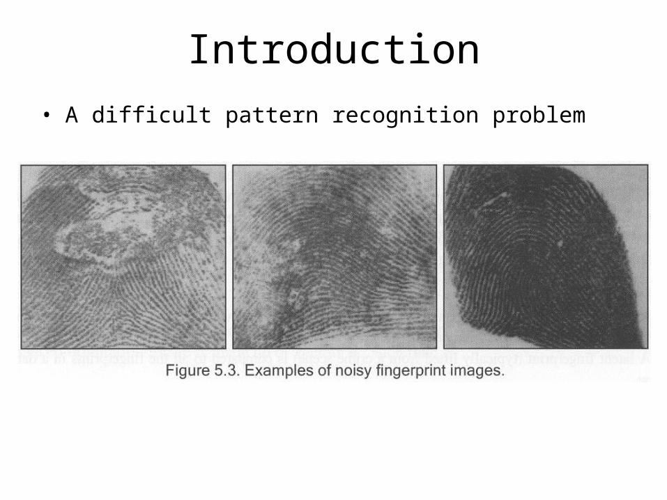
Introduction• A difficult pattern recognition problem
Introduction
• A difficult pattern recognition problem

Classification Techniques


Classification Techniques
1. Rule-based approachesClassification according to the number and position of the singularities (commonly used by human experts for manual classification).

Classification Techniquesa. Kawagoe and Tojo (1984)
– Derive a coarse classification using type and position of singular points.
– Finer classification is obtained by tracing the ridge line flow.

Classification Techniquesb. Karu and Jain (1996)
An iterative regularization (smoothening orientation image with a 3x3 box filter) is done until a valid number of singular points are detected. This allows reducing noise and thus improves classification accuracy.
• Criteria for differentiating between tented arches and loopsConnect the two singularities with a straight line and measure the avg. difference between the local orientations along the line and the slope of the line. A fingerprint is classified as a tented arch if:

Classification Techniques• Problems with Rule-based approaches:
– Although simple, some problems arise in presence of noisy or partial fingerprints, where singularity detection can be extremely difficult. (Addressed to some extent by Karu and Jain (1996) approach).
– May work well on rolled (nail to nail) fingerprint impressions scanned from cards, but are not suitable for dab (live-scan) fingerprint images, because delta points are often missing in these types of images.

Classification Techniques
2. Syntactic approaches– A syntactic method describes patterns by means of terminal symbols
and production rules.
– Terminal symbols are associated to small groups of directional elements within the orientation image and represent a class.
– A grammar is defined for each class and a parsing process is responsible for classifying each new pattern (Fu and Booth, 1986a, b).
Classification Techniques
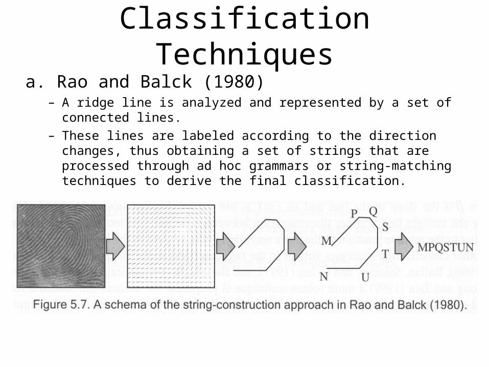
a. Rao and Balck (1980)– A ridge line is analyzed and represented by a set of connected lines.– These lines are labeled according to the direction changes, thus
obtaining a set of strings that are processed through ad hoc grammars or string-matching techniques to derive the final classification.
Classification Techniques
• Problems with Syntactic approaches:– Due to the great diversity of fingerprint patterns, syntactic
approaches require very complex grammars whose inference requires complicated and unstable approaches.
Classification Techniques
3. Structural approachesBased on the relational organization of low-level features into higher-level structures. This relational organization is represented by means of symbolic data structures (viz. trees and graphs), which allow a hierarchical organization of the information (Bunke, 1993).
Classification Techniques
a. Maio and Maltoni (1996)– The directional image is partitioned into several homogenous
regular-shaped regions, which are used to build a relational graph summarizing the fingerprint macro-features.
– Directional image is computed, over a discrete grid 32x32, using a robust technique proposed by Donahue and Rokhlin (1993).
– A dynamic clustering algorithm, Maio and Maltoni (1996), is adopted to segment the directional image.
– A relational graph is built by creating a node for each region and an arc for each pair of adjacent regions.
– An inexact graph matching technique, derived from Bunke and Allermann (1983), is used to compute a “distance” vector between the graph and each class prototype graph.

Classification Techniques
Fig.3. Main steps. The intermediate results produced during the classification of a Left Loop fingerprint are shown.
Class prototype graphs
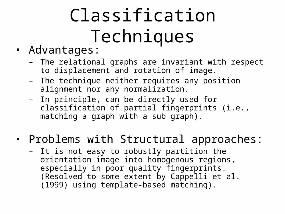
Classification Techniques• Advantages:
– The relational graphs are invariant with respect to displacement and rotation of image.
– The technique neither requires any position alignment nor any normalization.
– In principle, can be directly used for classification of partial fingerprints (i.e., matching a graph with a sub graph).
• Problems with Structural approaches:– It is not easy to robustly partition the orientation image into
homogenous regions, especially in poor quality fingerprints. (Resolved to some extent by Cappelli et al. (1999) using template-based matching).

Classification Techniques
4. Multiple classifier-based approachesDifferent classifiers offer complementary information about the patterns to be classified. This motivates combining of different approaches for the fingerprint classification task.

Classification Techniques
a. Candela et al. (1995)– Based on Neural Network and Rule-based approaches.– The system is called as PCASYS (Pattern-level Classification
Automation SYStem).– A probabilistic neural network is coupled with an auxiliary ridge
tracing module, specifically designed to detect whorl fingerprints.

Classification Techniques
Fig. A functional scheme of the PCASYS.

Classification Techniques
b. Jain, Prabhakar, and Hong (1999)– Two stage classification strategy based on Statistical and Neural
Network approaches.– Stage 1: A k-nearest neighbor classifier is used to find the two
most likely classes from a FingerCode feature vector (section 4.6).– Stage 2: A specific neural network, trained to distinguish between
the two classes, is utilized to obtain the final decision. A total of 10 neural networks are trained to distinguish between each possible pair of classes.

Classification Techniques

Fingerprint Classification by Directional Image Partitioning
Raffaele Cappelli, Alessandra Lumini,Dario Maio and Davide Maltoni.
IEEE TRANSACTIONS ON PATTERN ANALYSIS AND MACHINE INTELLIGENCE, vol. 21, no. 5, pp. 402-421, 1999.

Overview
• Fingerprint Classification by Directional Image Partitioning– Introduction.– The new approach.– Fingerprint retrieval.– Experimental results.– Conclusion.

Introduction
• The relational graph approach has some problems in obtaining analogous segmentation from similar directional images.
• Influenced too much by local ridge-line orientation changes, start point of clustering routines.
• The new approach uses dynamic masks for directional image partitioning.
• It is translation and rotation invariant and does not require the singularities to be detected.

Introduction
Fig. 4. The segmentation of two Left Loop fingerprints.

The New Approach
• Overview of the new approach.• Directional image computation and enhancement.• Dynamic mask definition.• Directional image partitioning with Dynamic masks.• Generation of a set of Prototype masks.• Classification.
Overview of the new approach
• The basic idea of the new approach is to perform a “guided” segmentation of the directional image with the aim of drastically reducing the degrees of freedom during the partitioning process, conferring stability to the solutions.
• A set of dynamic masks, directly derived from the most common fingerprint classes, are used to guide the partitioning.
• The inexact graph matching step is simplified and embedded in the segmentation step.

Overview of the new approach
Fig. 6. Classification of a Left Loop fingerprint by means of the dynamic masks approach.

Directional image computation and enhancement
• Directional image computation:– The finger area is separated from the background and its quality
is improved by a filtering in the frequency domain.– The R.M. Stock and C.W. Swonger (1969) method is applied to
calculate directional elements. Each element is represented by a vector v.
• Directional image enhancement:– Regularization:
Regularization of directional elements by local averaging on 3x3 windows W.
Directional image computation and enhancement
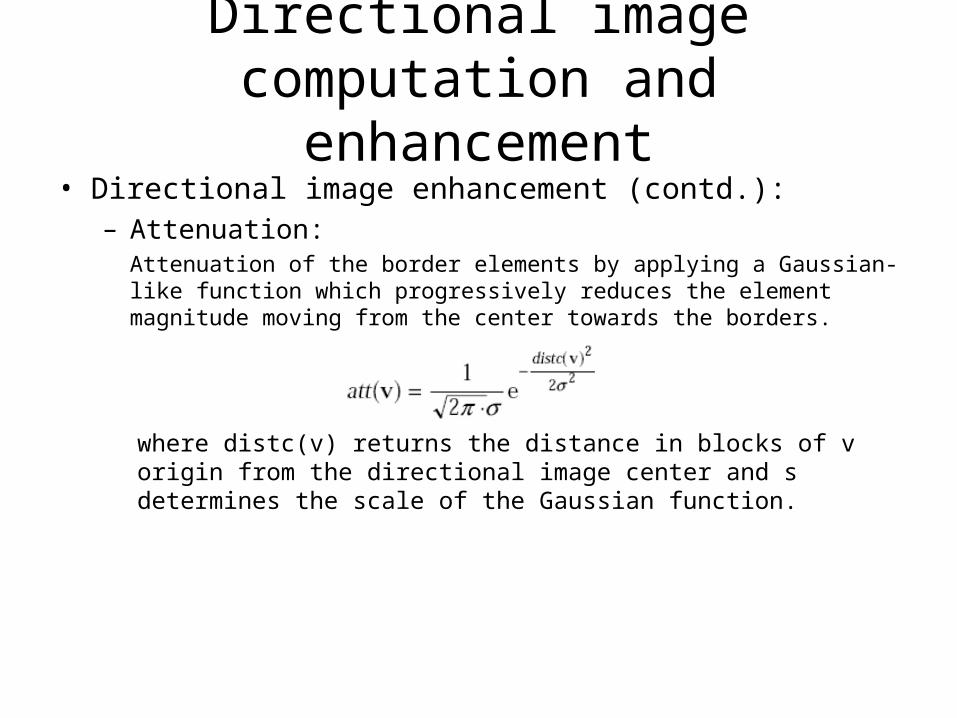
• Directional image enhancement (contd.):– Attenuation:
Attenuation of the border elements by applying a Gaussian-like function which progressively reduces the element magnitude moving from the center towards the borders.
where distc(v) returns the distance in blocks of v origin from the directional image center and s determines the scale of the Gaussian function.

Directional image computation and enhancement
• Directional image enhancement (contd.):– Strengthening:
We use a strengthening function (str) which increases the significance of each element according to the irregularity degree of its 3x3 neighborhood, without requiring the singularities to be explicitly detected.
returns 0 if all the vectors are parallel to each other and its value approaches 1 when discordance increases.
The resulting directional image is made up of vectors ve such that:
where is a weighting factor.

Directional image computation and enhancement
Fig. 7. Enhancement of a directional image: the map in the arrow-box shows the most irregular regions as revealed by the str function. The parametersare: s = 9.6 and l = 112.

Dynamic mask definition• Dynamic masks have been introduced in order to decrease the
degrees of freedom during the partitioning process.• Each mask is characterized by a set of vertices defining the borders
of the regions which determine the segmentation.• Some vertices can be locally moved to best fit the fingerprint image
singularities, which can occupy different positions within fingerprints of the same class.
Fig. 8. The singularity positions in three different Left Loop fingerprints.
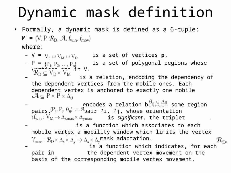
Dynamic mask definition• Formally, a dynamic mask is defined as a 6-tuple:
M = ,
where:– V = is a set of vertices p.
– P = is a set of polygonal regions whose vertices are in V.
– is a relation, encoding the dependency of the dependent vertices from the mobile ones. Each dependent vertex is anchored to exactly one mobile vertex.
– encodes a relation between some region pairs. For each pair Pi, Pj, whose orientation difference is significant, the triplet .
– is a function which associates to each mobile vertex a mobility window which limits the vertex movements during the mask adaptation.
– is a function which indicates, for each pair in the dependent vertex movement on the basis of the corresponding mobile vertex movement.
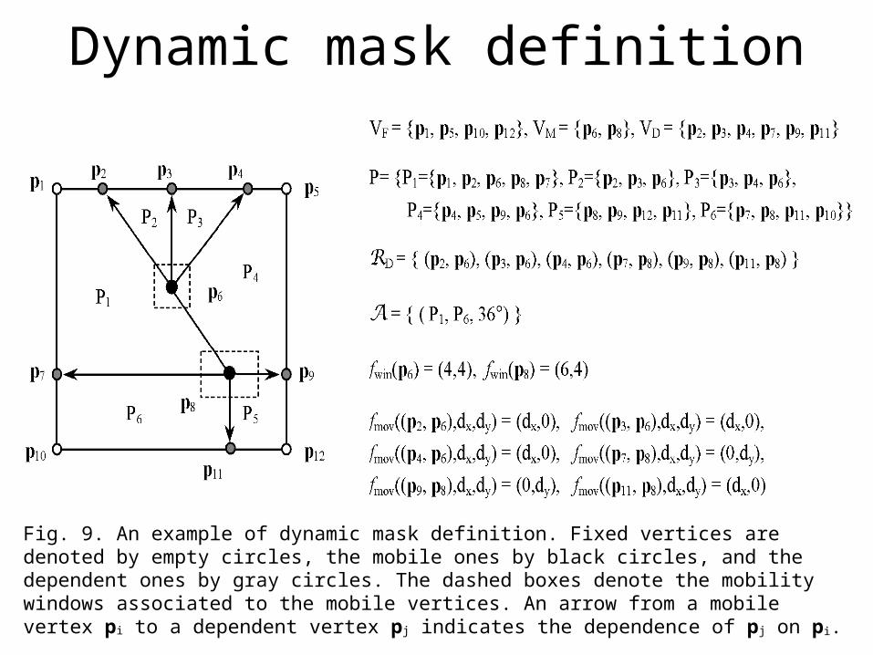
Dynamic mask definition
Fig. 9. An example of dynamic mask definition. Fixed vertices are denoted by empty circles, the mobile ones by black circles, and the dependent ones by gray circles. The dashed boxes denote the mobility windows associated to the mobile vertices. An arrow from a mobile vertex pi to a dependent vertex pj indicates the dependence of pj on pi.

Directional image partitioning with Dynamic masks
• Let MT,Q be the steady mask obtained by the dynamic mask M as a result of the following transformations:– a global rotation-displacement T = where and denote the
global mask displacement and denotes the global mask rotation.
– a set of mobile vertex displacements Q = { (dx1, dy1), (dx2, dy2), ... }; (dxi, dyi) denotes the displacement of the vertex pi with respect to its initial position.
• The application of a steady mask MT,Q to a directional image D consists in superimposing MT,Q on D and deriving a segmentation R = {R1, R2, ..., Rn} where each region Ri is made up of the directional elements internal to the polygon Pi.
Directional image partitioning with Dynamic masks
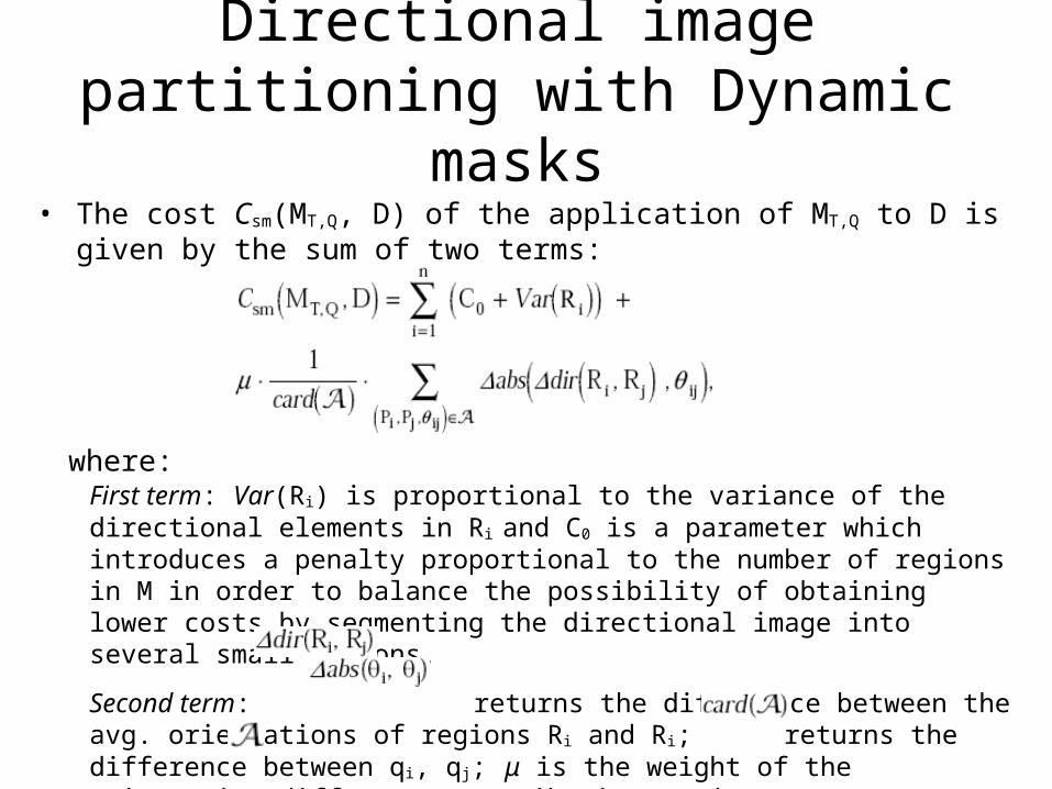
• The cost Csm(MT,Q, D) of the application of MT,Q to D is given by the sum of two terms:
where:First term: Var(Ri) is proportional to the variance of the directional elements in Ri and C0 is a parameter which introduces a penalty proportional to the number of regions in M in order to balance the possibility of obtaining lower costs by segmenting the directional image into several small regions.
Second term: returns the difference between the avg. orientations of regions Ri and Ri; returns the difference between qi, qj; μ is the weight of the orientation difference contribution, and returns the number of triplets in .
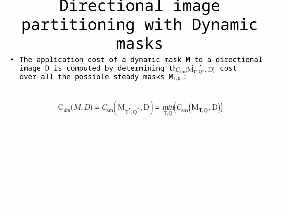
Directional image partitioning with Dynamic masks
• The application cost of a dynamic mask M to a directional image D is computed by determining the minimum cost over all the possible steady masks MT,Q :
Directional image partitioning with Dynamic masks
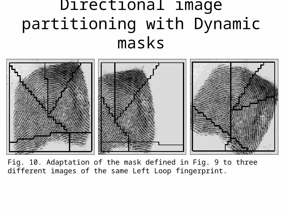
Fig. 10. Adaptation of the mask defined in Fig. 9 to three different images of the same Left Loop fingerprint.
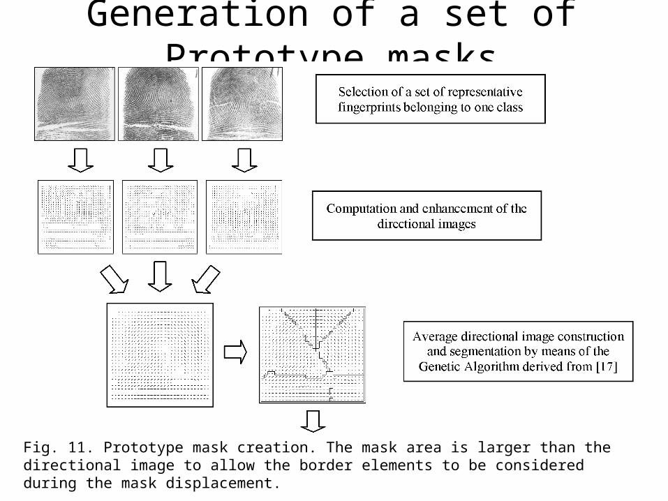
Generation of a set of Prototype masks
Fig. 11. Prototype mask creation. The mask area is larger than the directional image to allow the border elements to be considered during the mask displacement.

Fig. 11 (contd.). Prototype mask creation. The mask area is larger than the directional image to allow the border elements to be considered during the mask displacement.
Generation of a set of Prototype masks
Generation of a set of Prototype masks
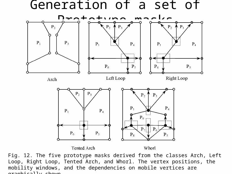
Fig. 12. The five prototype masks derived from the classes Arch, Left Loop, Right Loop, Tented Arch, and Whorl. The vertex positions, the mobility windows, and the dependencies on mobile vertices are graphically shown.

Generation of a set of Prototype masks
Fig. 12 (contd.). Example of application of each mask to a fingerprint belonging to the corresponding class.
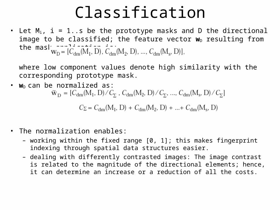
Classification• Let Mi, i = 1..s be the prototype masks and D the directional image to be
classified; the feature vector wD resulting from the mask application is:
where low component values denote high similarity with the corresponding prototype mask.
• wD can be normalized as:
• The normalization enables:– working within the fixed range [0, 1]; this makes fingerprint indexing through
spatial data structures easier.
– dealing with differently contrasted images: The image contrast is related to the magnitude of the directional elements; hence, it can determine an increase or a reduction of all the costs.
Classification
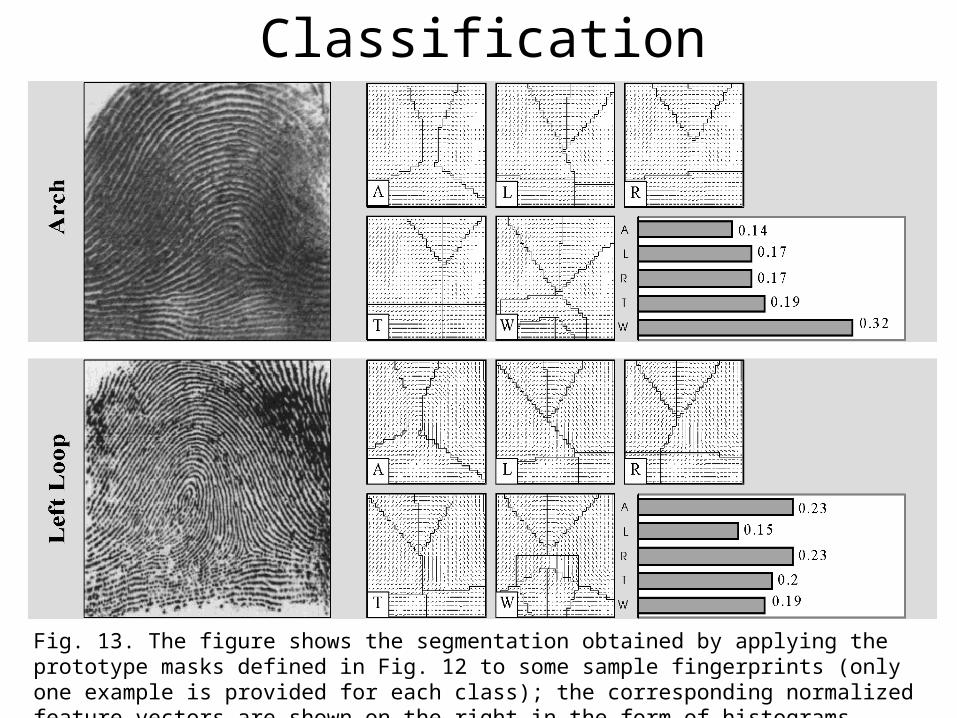
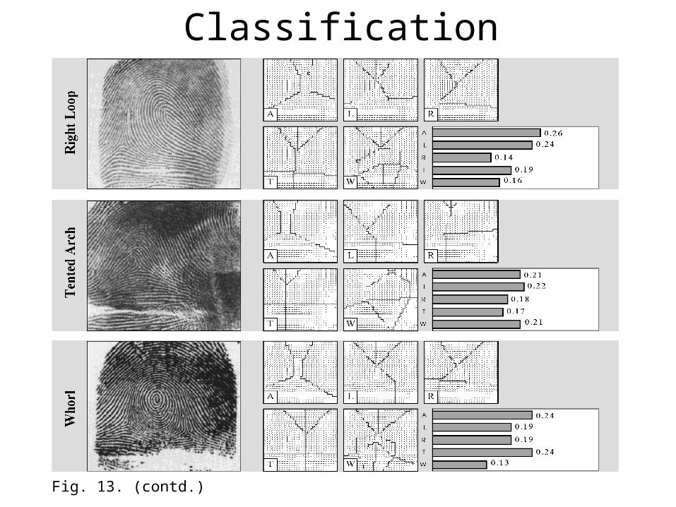
Fig. 13. The figure shows the segmentation obtained by applying the prototype masks defined in Fig. 12 to some sample fingerprints (only one example is provided for each class); the corresponding normalized feature vectors are shown on the right in the form of histograms.
Classification
Fig. 13. (contd.)
Fingerprint retrieval
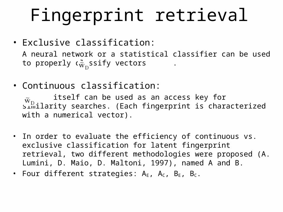
• Exclusive classification:A neural network or a statistical classifier can be used to properly classify vectors .
• Continuous classification: itself can be used as an access key for similarity searches. (Each fingerprint is characterized with a numerical vector).
• In order to evaluate the efficiency of continuous vs. exclusive classification for latent fingerprint retrieval, two different methodologies were proposed (A. Lumini, D. Maio, D. Maltoni, 1997), named A and B.
• Four different strategies: AE, AC, BE, BC.
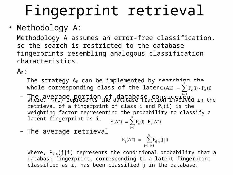
Fingerprint retrieval• Methodology A:
Methodology A assumes an error-free classification, so the search is restricted to the database fingerprints resembling analogous classification characteristics.
AE:The strategy AE can be implemented by searching the whole corresponding class of the latent fingerprint.
– The average portion of database considered:
– The average retrieval error:
Where, Pd(i) represents the database fraction involved in the retrieval of a fingerprint of class i and Pc(i) is the weighting factor representing the probability to classify a latent fingerprint as i.
Where, Pd|c(j|i) represents the conditional probability that a database fingerprint, corresponding to a latent fingerprint classified as i, has been classified j in the database.

Fingerprint retrieval• Methodology A:
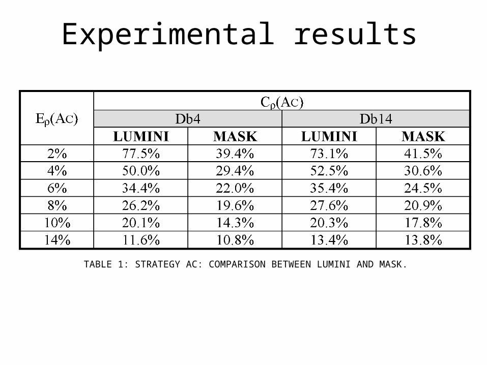
AC:The strategy AC can be implemented by searching among those fingerprints which are less far from the feature vector w of the latent fingerprint than a fixed tolerance ρ.
Given a fixed ρ,
– The average portion of database considered Cρ(AC) is determined by the average number of fingerprints inside the hyper-sphere with radius ρ, centered in the latent fingerprint.
– The average retrieval error Eρ(AC) is determined by the average number of missed retrievals inside the search area.

Fingerprint retrieval• Methodology B:
– Methodology B allows for misclassification to be taken into account; to this aim, the search is carried out incrementally over the whole database, avoiding any possible retrieval error.
– This methodology requires the search to be terminated when a human expert finds a real correspondence between the latent fingerprint and a database fingerprint that has already been considered.
BE:The strategy BE can be implemented by starting the search from the latent fingerprint class, and incrementally extending it to the other classes.
BC:The strategy BC can be carried out by processing fingerprints according to their distance from the latent fingerprint feature vector w.

Experimental results
• Databases used:– NIST Special Database 4 (Db4) contains 2,000 fingerprint pairs, uniformly
distributed in the five classes, in order to resemble a real distribution.
– NIST Special Database 14 (Db14) contains 27,000 fingerprint pairs randomly taken, thus approximating the real fingerprint distribution; only the last 2,700 fingerprint pairs have been employed in the simulation.
– The first 2,000 fingerprints of Db14 have been used as “training set” to derive the set of prototype masks and to optimize the parameters.
– MASK: the dynamic mask method introduced in this paper.
– LUMINI: the continuous classification approach described in A. Lumini, D. Maio, D. Maltoni (1997).
– PCASYS: the exclusive approach by NIST (G.T. Candela, et al., 1995).

Experimental results
Fig. 14. MASK results over Db4 (a) and Db14 (b); the average portion of database considered Cρ(AC) and the average retrieval error Eρ(AC) are plotted as a function of ρ.
Experimental results
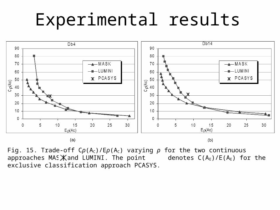
Fig. 15. Trade-off Cρ(AC)/Eρ(AC) varying ρ for the two continuous approaches MASK and LUMINI. The point denotes C(AE)/E(AE) for the exclusive classification approach PCASYS.
Experimental results
TABLE 1: STRATEGY AC: COMPARISON BETWEEN LUMINI AND MASK.

Experimental results
TABLE 2: COMPARISON AMONG PCASYS, LUMINI, AND MASK FIXING THE AVERAGE PORTION OF DATABASE READ.
TABLE 3: COMPARISON BETWEEN THE AVERAGE PERCENTAGES OF DATABASE SEARCHED (METHODOLOGY B).
Experimental results
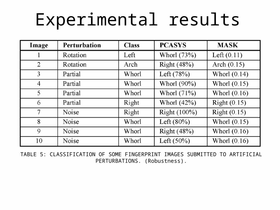
TABLE 5: CLASSIFICATION OF SOME FINGERPRINT IMAGES SUBMITTED TO ARTIFICIAL PERTURBATIONS. (Robustness).
Experimental results
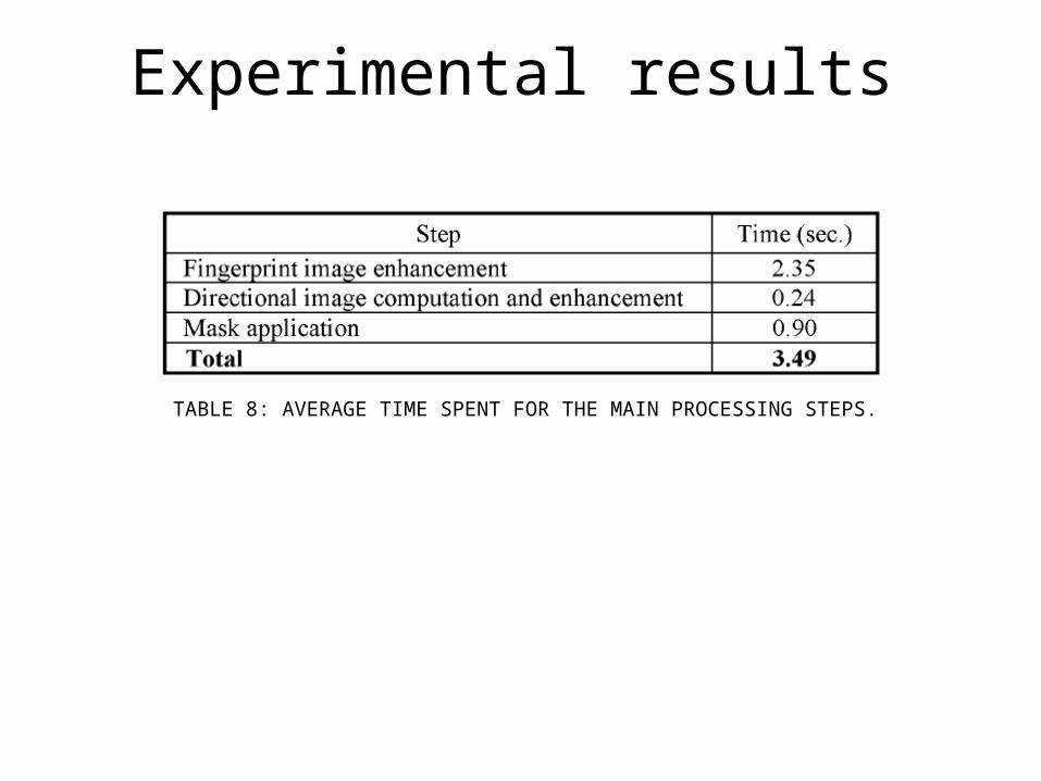
TABLE 8: AVERAGE TIME SPENT FOR THE MAIN PROCESSING STEPS.

Conclusion
• Dynamic masks have been defined as a powerful instrument for a robust segmentation. (Noisy and partial fingerprint images).
• The experimental results prove the accuracy and robustness of the new method.
• The comparison with other techniques demonstrates its superiority for the continuous classification task, especially if fingerprints are classified only for improving the retrieval efficiency.
• Continuous classification does not enable to accomplish some tasks to be carried out, such as fingerprint labeling according to a given classification scheme.

Thank you.