financial support for this document has been provided by ... info/domestic water well... ·...
TRANSCRIPT


Financial support for this document has been provided by the Agriculture Council of Saskatchewan through the Canadian Adaptation and Rural Development Fund in Saskatchewan (CARDS) program. Funding for the CARDS program is provided by Agriculture and Agri-Food Canada.

Authors and Contributions
Author: Elisabeth Mance
Contributions from: Curtis Paterson, Joanne Sketchell
Acknowledgements
We gratefully acknowledge the work of the steering committee in overseeing and guiding the creation of this publication from concept to production: Randy Beler, Michael Friesen, Tom Harrison, Bill Henley, Lyndon Hicks, Sharon Metz, Curtis Paterson, Nolan Shaheen, and Terry Sled. We would also like to thank those staff members from the Saskatchewan Ministry of Environment and the Saskatchewan Ministry of Health who contributed technical information to this document.
Landowner Review
We are extremely grateful to those landowners who provided us with their comments and feedback on this document. Your input was vital to ensuring that this guide provides the information landowners need to manage their water wells and be good stewards of our groundwater resources.
Sources of Information
We acknowledge the following sources of information which were used extensively in the preparation of this guide: B. Buchanan et al.’s Water Wells… That Last for Generations; F.G. Driscoll’s Groundwater and Wells; and the Saskatchewan Ministry of Agriculture’s The Saskatchewan Environmental Farm Plan.
We also acknowledge the following sources for the use of pictures and/or diagrams: Alberta Agriculture and Food, Centre for Ecology and Hydrology; the Natural Environment Research Council; F.G. Driscoll’s Groundwater and Wells; Environment Canada; GlobalSecurity.org; the Idaho Museum of Natural History; Agriculture and Agri-Food Canada - Agri-Environment Services Branch; quantumlynx.com; the United States Department of Agriculture: Natural Resources Conservation Service; and the US Environmental Protection Agency.

T a b l e o f C o n T e n T s
INTRODUCTION ..............................................................................................................................................................................1
Chapter 1: Groundwater .................................................................................................................... 1
WHaT Is GRoUnDWaTeR? .............................................................................................................................. 1AQUIFERS AND AQUITARDS ................................................................................................................................................2CONFINED AND UNCONFINED AQUIFERS ..........................................................................................................................2GROUNDWATER RECHARGE ...............................................................................................................................................3AQUIFERS OF SASKATCHEWAN ..........................................................................................................................................3WELL YIELDS IN SASKATCHEWAN ......................................................................................................................................4
GRoUnDWaTeR QUalITY In sasKaTCHeWan .............................................................................................. 5
naTURal faCToRs affeCTInG GRoUnDWaTeR QUalITY ........................................................................... 6DEPTH FROM SURFACE .......................................................................................................................................................6PERMEABILITY OF SEDIMENTS ...........................................................................................................................................6CLIMATIC VARIATIONS.........................................................................................................................................................6
Chapter 2: Water Well Development ................................................................................................ 7
PlannInG WaTeR sYsTeMs .......................................................................................................................... 7WATER SOURCES .................................................................................................................................................................7SIZING THE WATER SUPPLY .................................................................................................................................................7
Water Requirements ........................................................................................................................................................7Water Sources..................................................................................................................................................................9
WELL SITING .........................................................................................................................................................................9
DesIGn anD ConsTRUCTIon of WaTeR Wells ......................................................................................... 11WELL DESIGN .....................................................................................................................................................................11
Well Depth ......................................................................................................................................................................11Types of Wells ................................................................................................................................................................12Casing Size and Type .....................................................................................................................................................13Intake Design .................................................................................................................................................................14Annulus Seal ..................................................................................................................................................................16
WELL COMPLETION ...........................................................................................................................................................17Well Development .........................................................................................................................................................17Yield Test ........................................................................................................................................................................17Disinfecting the Well ......................................................................................................................................................17
Well ManaGeMenT .................................................................................................................................... 18WATER LEVEL MEASUREMENTS .......................................................................................................................................18
Water Level Measurement Methods ............................................................................................................................18Interpreting Water Levels ..............................................................................................................................................20
WATER QUALITY MEASUREMENTS ...................................................................................................................................21Method of Collection .....................................................................................................................................................22Bacterial and Nitrate Analysis .......................................................................................................................................22Chemical Analysis ..........................................................................................................................................................22
Well MaInTenanCe .................................................................................................................................... 22IDENTIFYING IRON AND SULFATE-REDUCING BACTERIA .................................................................................................22
Bacteria Growth .............................................................................................................................................................22

Staining Problems ..........................................................................................................................................................22Taste and Odour ............................................................................................................................................................22Regular Disinfection ......................................................................................................................................................23
CoMMon Well PRobleMs .......................................................................................................................... 23IMPROPER WELL DESIGN AND CONSTRUCTION ..............................................................................................................23INCOMPLETE WELL DEVELOPMENT .................................................................................................................................23BOREHOLE INSTABILITY ....................................................................................................................................................23SAND PUMPING .................................................................................................................................................................23INCRUSTATION...................................................................................................................................................................23
Carbonate ......................................................................................................................................................................24Iron and Manganese ......................................................................................................................................................24Biofouling .......................................................................................................................................................................24
PLUGGING OF SCREEN AND SURROUNDING FORMATION ..............................................................................................24CORROSION .......................................................................................................................................................................24FAILURES LINKED TO THE RESOURCE ...............................................................................................................................24
Chapter 3: Protecting Wells from Contamination ........................................................................ 25
Well HeaD PRoTeCTIon.............................................................................................................................. 25PROPER WELL SITING ........................................................................................................................................................25PROPER WELL CONSTRUCTION ........................................................................................................................................25WELL CONTAMINATION DURING MAINTENANCE ............................................................................................................26IMPROPERLY DECOMMISSIONED WELLS ..........................................................................................................................26WELL PITS ..........................................................................................................................................................................26WATER HYDRANTS INSTALLED IN A WELL OR WELL PIT ..................................................................................................27
aQUIfeR PRoTeCTIon .................................................................................................................................. 28ONSITE WASTEWATER SYSTEMS ......................................................................................................................................28FUEL STORAGE TANKS ......................................................................................................................................................29PESTICIDE CONTAMINATION ............................................................................................................................................29MANURE AND FERTILIZER CONTAMINATION ...................................................................................................................29IMPROPER STORAGE OF SILAGE ......................................................................................................................................30LIVESTOCK YARDS .............................................................................................................................................................30DISPOSAL OF FARM WASTES ............................................................................................................................................30
Chapter 4: Abandoned Wells ........................................................................................................... 31DECOMMISSIONING ABANDONED WELLS ........................................................................................................................32
Conclusion ......................................................................................................................................... 36
Appendix ............................................................................................................................................ 39
DRIllInG ConTRaCToRs .............................................................................................................................. 39CHOOSING A DRILLING CONTRACTOR .............................................................................................................................39WATER WELL DRILLING AGREEMENTS ..............................................................................................................................39WATER WELL DRILLING AGREEMENT FORM .....................................................................................................................40WATER WELL DRILLING REPORTS .....................................................................................................................................44
Driller’s Report ...............................................................................................................................................................44Electric and Other Logs .................................................................................................................................................44
CHloRIne DIsInfeCTIon PRoCeDURes ...................................................................................................... 45
DRInKInG WaTeR QUalITY sTanDaRDs anD obJeCTIVes ........................................................................ 48
GRoUnDWaTeR ManaGeMenT anD leGal ReQUIReMenTs .................................................................... 50INVENTORY OF GROUNDWATER RESOURCES IN SASKATCHEWAN ................................................................................50ALLOCATION AND LICENSING ...........................................................................................................................................50
Development of a Groundwater Source .......................................................................................................................50GROUNDWATER REGULATIONS AND LEGISLATION .........................................................................................................50
Water Resources Legislation .........................................................................................................................................50Water Quality Legislation ...............................................................................................................................................51Regulations ....................................................................................................................................................................51
ConTaCTs anD oTHeR soURCes of InfoRMaTIon .................................................................................. 52AGRICULTURE AND AGRI-FOOD CANADA - AGRI-ENVIRONMENT SERVICES BRANCH ..................................................52
North Saskatchewan .....................................................................................................................................................52South Saskatchewan .....................................................................................................................................................52
CANADIAN GROUND WATER ASSOCIATION .....................................................................................................................53SASKATCHEWAN MINISTRY OF AGRICULTURE .................................................................................................................53
Regional Offices .............................................................................................................................................................53SASKATCHEWAN MINISTRY OF ENVIRONMENT ...............................................................................................................53SASKATCHEWAN MINISTRY OF HEALTH ...........................................................................................................................54 SASKATCHEWAN WATERSHED AUTHORITY ....................................................................................................................55
Head Office ....................................................................................................................................................................55Regional Offices .............................................................................................................................................................55Other Offices ..................................................................................................................................................................55
SASKWATER .......................................................................................................................................................................56Head Office ....................................................................................................................................................................56Other Offices ..................................................................................................................................................................5624 Hour Emergency Number ........................................................................................................................................56
WATER QUALITY ................................................................................................................................................................56Accredited Water Analysis Laboratories in Saskatchewan ..........................................................................................56
RefeRenCes ................................................................................................................................................. 57

8

1
I n T R o D U C T I o n
Groundwater accounts for the majority of the world’s useable freshwater. It is an important source of water for many
municipalities and industries, and for irrigation, suburban homes, and farms. Saskatchewan has about 60,000 water wells,
providing water for municipalities, agriculture, industry and domestic needs.
As with any natural resource, groundwater supplies are not unlimited. They must be wisely managed and protected against
undue exploitation and influence by contaminants. This guide is intended to provide domestic water well owners with a brief
overview of groundwater, well construction, well management, and well decommissioning.
I n T R o D U C T I o n
C H a P T e R 1
GroundwaterWhat is Groundwater?
Groundwater is an important part of the earth’s water cycle.
Water continuously circulates between land, air and ocean
in the form of rain, snow, water vapour, surface water and
groundwater. Groundwater starts off as surface water or
precipitation and enters the ground through areas generally
referred to as recharge areas.
Groundwater is water that occurs beneath the ground surface
in the cracks and void spaces in soil, sand and rock. The area
where water completely fills the pore spaces is called the
saturated zone. The top of the saturated zone is the water
table. Between the water table and the ground surface, some
of the pore spaces are not completely filled with water, and
this gives rise to the term unsaturated zone.
Figure 1: The Hydrological Cycle

2
aquifers and aquitards
Rock or soil that is completely saturated with water can be
classified into two categories:
• Aquifers
• Aquitards
Aquifers are formations from which water can be removed
economically. Although water moves through an aquifer, it
is not an underground river. Typically, aquifers are made up
of sediments with relatively large and connected pore spaces
that permit water movement. Aquifers are most commonly
composed of sands and gravels, but in some areas may be
formed by cracked or fractured coal or shale.
Aquifers can be overlain or underlain by confining layers
(aquitards), which are soil and rock formations like clays
and silts that permit slower movement of groundwater.
Although these materials can be saturated with groundwater,
they are not able to yield sufficient water to a well. Flow
within aquitards is limited within small areas, but regionally
they may transmit significant volumes of water. Aquitards
can therefore significantly affect the flow and quality of
groundwater because they influence recharge and the flow
between aquifers.
Confined and Unconfined aquifers
Unconfined aquifers are often called water table aquifers,
as their upper boundary is the water table. An unconfined
aquifer does not have a confining layer (an aquitard) between
it and the surface, so groundwater levels are free to rise or fall
with changes in recharge and discharge, as well as barometric
pressure. The volume of water in an unconfined aquifer is
mainly dependent on recharge, and tends to vary seasonally.
Typically, groundwater levels will be at their highest following
spring snowmelt.
Confined aquifers occur when groundwater is restricted
under pressure by an overlying confining layer. If a well
penetrates a confined aquifer, the water level in the well will
rise above the top of the aquifer. Confined aquifers are also
known as artesian aquifers. If the pressure in the aquifer
causes the water level in the well to reach the ground surface,
it is called a flowing artesian well.
Figure 2: Aquifers and Aquitards

3
Groundwater Recharge
Recharge is the process by which groundwater is
replenished. Groundwater can be recharged both by
precipitation moving down through the soil and rock layers
of the ground and by infiltration from surface water sources
such as rivers and lakes. Springs and seeps are discharge
areas where groundwater leaves the aquifer and flows to the
surface. This discharge can represent a significant portion
of the input water to a surface water source and can affect
its quality. Therefore, groundwater’s natural recharge and
quality, and consequently surface water’s quality, can be
affected by human activities on the surface.
aquifers of saskatchewan
There are two main types of aquifers in Saskatchewan:
• BedrockAquifers
• QuaternaryAquifers
Bedrock aquifers in Saskatchewan are usually composed
of sandstone, but in some limited areas they may also be
formed by fractured shale or coal. They tend to be found at
depths in excess of 100 metres, but in some areas may be
encountered at much more shallow depths. They are usually
overlain by thick, low permeability aquitards. For this reason,
groundwater levels in bedrock aquifers tend not to fluctuate
significantly with short-term variations in surface moisture
conditions. Major bedrock aquifers in Saskatchewan include
the Judith River formation and the Eastend to Ravenscrag
formations.
Quaternary aquifers are defined as the aquifers occurring
between the bedrock surface and the ground surface. In
Saskatchewan, they are composed of gravels, sands and
silts. These aquifers vary greatly in size, in some cases being
adequate only for limited domestic use, while in other cases
being able to provide sufficient supplies for large-scale
industrialandmunicipaluse.Quaternaryaquifersarethe
most common groundwater source in Saskatchewan.
Types of Quaternary Aquifers
Buried valley aquifers are preglacial valleys cut into
bedrock sediments that contain extensive thicknesses of
coarse sand and gravel deposits. Major buried valley aquifers
in Saskatchewan include the Hatfield Valley and Tyner Valley
aquifers. These types of aquifers are capable of supporting
high-yielding wells.
Blanket aquifers are usually quite large and consist
of gravels, silts and tills. The main blanket aquifers in
Saskatchewan include the Pathlow, Meacham and Wynyard-
Melville aquifers.
Intertill aquifers are composed of glacial gravels, sands,
and silts positioned between layers of till. These aquifers are
extremely variable in size and productive capacity. They are
found throughout southern Saskatchewan, with some of the
major ones located around Regina and Saskatoon. These
aquifers are probably the most common groundwater source
in the province, providing the supply for many domestic,
municipal and industrial users.
Surficial aquifers are composed of stratified deposits of
sand, gravel, silt and clay, and occur at, or very near, the
surface. They are located throughout southern Saskatchewan
and vary greatly in size. These aquifers are generally low-
yielding and only provide enough water for domestic
supplies. Moreover, when these shallow aquifers are not
insulated from the ground surface by an appreciable
thickness of aquitard, they can show seasonal changes in
water level and can be sensitive to drought.

4
Well Yields in saskatchewan
For domestic uses, wells should ideally produce water at
a rate of 0.375-0.75 litres per second (5-10 gallons per
minute). If wells produce less than 0.375 L/s (5 gpm) for a
one-hour peak use period, then additional storage in the form
of a tank or cistern might be necessary. It should be noted,
however, that with proper design, many farms can obtain an
adequate supply from a well capable of producing only 0.075
L/s or 0.15 L/s (1 or 2 gpm). In the case of farms where a
higher quantity of water is required, a well should be capable
of providing a minimum of 0.75 L/s (10 gpm) for at least two
continuous hours.
Well yields in Saskatchewan are highly variable. Buried
valley aquifers and some of the large intertill aquifers may
have yields of several hundred gallons per minute. Bedrock
aquifers and small quaternary aquifers will have relatively low
yields, often sufficient only for domestic purposes. Bedrock
aquifers rarely yield more than ten gallons per minute. Well
yields depend on a number of factors, but in general, aquifer
thickness and the characteristics of the aquifer material
are the main influences on well yields. For example, a well
completed in an aquifer formed by well-sorted gravel will
have a higher yield than a well completed in an aquifer
formed by very fine silty sand of similar thickness.
Figure 3: A sample cross-section of Quaternary Formations in southern Saskatchewan
5
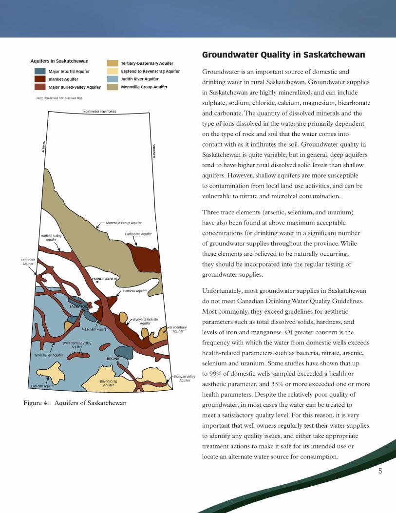
Groundwater Quality in Saskatchewan
Groundwater is an important source of domestic and
drinking water in rural Saskatchewan. Groundwater supplies
in Saskatchewan are highly mineralized, and can include
sulphate, sodium, chloride, calcium, magnesium, bicarbonate
and carbonate. The quantity of dissolved minerals and the
type of ions dissolved in the water are primarily dependent
on the type of rock and soil that the water comes into
contact with as it infiltrates the soil. Groundwater quality in
Saskatchewan is quite variable, but in general, deep aquifers
tend to have higher total dissolved solid levels than shallow
aquifers. However, shallow aquifers are more susceptible
to contamination from local land use activities, and can be
vulnerable to nitrate and microbial contamination.
Three trace elements (arsenic, selenium, and uranium)
have also been found at above maximum acceptable
concentrations for drinking water in a significant number
of groundwater supplies throughout the province. While
these elements are believed to be naturally occurring,
they should be incorporated into the regular testing of
groundwater supplies.
Unfortunately, most groundwater supplies in Saskatchewan
donotmeetCanadianDrinkingWaterQualityGuidelines.
Most commonly, they exceed guidelines for aesthetic
parameters such as total dissolved solids, hardness, and
levels of iron and manganese. Of greater concern is the
frequency with which the water from domestic wells exceeds
health-related parameters such as bacteria, nitrate, arsenic,
selenium and uranium. Some studies have shown that up
to 99% of domestic wells sampled exceeded a health or
aesthetic parameter, and 35% or more exceeded one or more
health parameters. Despite the relatively poor quality of
groundwater, in most cases the water can be treated to
meet a satisfactory quality level. For this reason, it is very
important that well owners regularly test their water supplies
to identify any quality issues, and either take appropriate
treatment actions to make it safe for its intended use or
locate an alternate water source for consumption.
Figure 4: Aquifers of Saskatchewan
6
Natural Factors Affecting Groundwater Quality
By understanding the factors that affect groundwater quality,
landowners can manage their farms and wells in order to
avoid water contamination. There are several factors that
affect groundwater quality:
• Depthfromsurface
• Permeabilityofsediments
• Climaticvariations
Depth from surface
Water is the world’s most abundant natural solvent.
Therefore, as it moves through the ground it dissolves
minerals. These minerals are known as the total dissolved
solids (TDS) present in the water. In a shallow aquifer the
water has a shorter distance to travel through the ground,
and therefore tends to have a lower level of mineralization.
Conversely, deeper aquifers tend to contain more dissolved
solids. Shallow aquifers, however, are more susceptible to
contamination from local land use activities, and can be
vulnerable to nitrate and microbial contamination.
Permeability of sediments
The amount of water that moves through the unsaturated
zone is an important determinant of the extent of
groundwater mineralization. Groundwater moves slowly
through sediments with a low permeability, such as clay
and silt. This slow movement allows more time for minerals
to dissolve. Sediments with high permeability such as sand
and gravel, on the other hand, allow groundwater to move
through them more quickly. This results in a lower level of
dissolved minerals.
Climatic Variations
Climatic variations such as rainfall and evaporation can affect
groundwater quality. In semi-arid regions where discharging
groundwater evaporates, precipitation infiltrating through
the soil can re-dissolve salts and carry them back to the
groundwater. In areas with higher precipitation and lower
evaporation, precipitation reaching the groundwater is less
mineralized.
7
C H a P T e R 22
Water Well DevelopmentProper well development is an important part of groundwater
protection, as water wells can provide a direct path for
contaminants to reach groundwater. It is important to
properly plan and maintain water well systems in order to
avoid contamination, protect aquifers from depletion, and
ensure supply.
Planning Water Systems
A water system includes:
• Watersources
• Pumps
• Distributionsystemsincludingpipelines,automatic
waterers, hydrants and home plumbing
• Watertreatmentequipment
Before beginning well construction, it is important to
determine the amount of water available from current on-
farm water sources, the potential available groundwater if a
new well is drilled, the water quality of all sources, and all of
the potential uses of the water. Water requirements should be
established and provisions should be made for any changes
that might occur in the near future.
Water sources
The Saskatchewan Watershed Authority can be consulted for
information on aquifers in the province (please refer to page
55 for contact information). This information can help people
determine the potential groundwater supply at a given site.
Information can also be gained from discussions with nearby
well owners and certified well drillers.
After the completion of a test hole, a water well driller may
use an electric logging device to E-log the test hole. An E-log
can only be run in an uncased hole filled with drilling fluid.
The E-log assists the driller in interpreting the formation
characteristics of the test hole. It provides information on the
depth, character of material, and relative quality of water in
the formation.
sizing the Water supply
Water Requirements
It is important to determine the amount of water required
before beginning to drill a well. An inventory must be taken
of all current and future water needs, as well as all water
sources available.
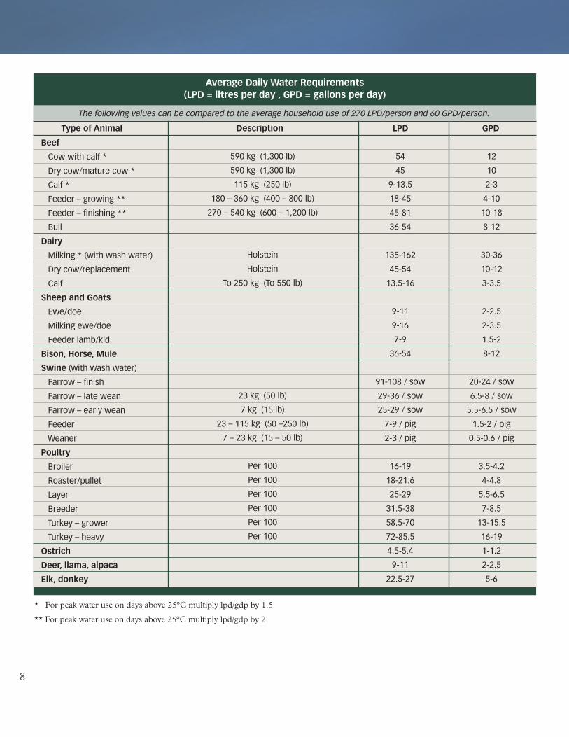
The following table provides average daily water
requirements for both household and livestock use.
These values can be added to other water uses, such as
lawn watering, to determine total water need. It must be
noted, however, that the quantity of water that livestock
will consume depends on a number of physiological and
environmental factors, such as:
• Typeandsizeofanimal
• Physiologicalstateofanimal(lactating,pregnantor
growing)
• Activitylevel(moreactiveanimalsrequiremorewater)
• Typeofdietandamountconsumed(dryhay,silageor
lush pasture)
• Temperature(hotdayswillincreasewaterconsumption)
• Waterquality(palatabilityandsaltcontent)
• Easeofaccess(livestockwillconsumelessifaccessto
the water source is difficult)
8
* For peak water use on days above 25°C multiply lpd/gdp by 1.5** For peak water use on days above 25°C multiply lpd/gdp by 2
average Daily Water Requirements (lPD = litres per day , GPD = gallons per day)
beef
Cow with calf *
Dry cow/mature cow *
Calf *
Feeder – growing **
Feeder – finishing **
Bull
Dairy
Milking * (with wash water)
Dry cow/replacement
Calf
sheep and Goats
Ewe/doe
Milking ewe/doe
Feeder lamb/kid
bison, Horse, Mule
swine (with wash water)
Farrow – finish
Farrow – late wean
Farrow – early wean
Feeder
Weaner
Poultry
Broiler
Roaster/pullet
Layer
Breeder
Turkey – grower
Turkey – heavy
ostrich
Deer, llama, alpaca
elk, donkey
590 kg (1,300 lb)
590 kg (1,300 lb)
115 kg (250 lb)
180 – 360 kg (400 – 800 lb)
270 – 540 kg (600 – 1,200 lb)
Holstein
Holstein
To 250 kg (To 550 lb)
23 kg (50 lb)
7 kg (15 lb)
23 – 115 kg (50 –250 lb)
7 – 23 kg (15 – 50 lb)
Per 100
Per 100
Per 100
Per 100
Per 100
Per 100
54
45
9-13.5
18-45
45-81
36-54
135-162
45-54
13.5-16
9-11
9-16
7-9
36-54
91-108 / sow
29-36 / sow
25-29 / sow
7-9 / pig
2-3 / pig
16-19
18-21.6
25-29
31.5-38
58.5-70
72-85.5
4.5-5.4
9-11
22.5-27
12
10
2-3
4-10
10-18
8-12
30-36
10-12
3-3.5
2-2.5
2-3.5
1.5-2
8-12
20-24 / sow
6.5-8 / sow
5.5-6.5 / sow
1.5-2 / pig
0.5-0.6 / pig
3.5-4.2
4-4.8
5.5-6.5
7-8.5
13-15.5
16-19
1-1.2
2-2.5
5-6
The following values can be compared to the average household use of 270 LPD/person and 60 GPD/person.
Type of animal Description lPD GPD
* For peak water use on days above 25°C multiply lpd/gdp by 1.5
** For peak water use on days above 25°C multiply lpd/gdp by 2

9
Water Sources
It is important to determine whether the available water
sources are sufficient to meet both the average water
requirements as well as peak demand days throughout the
year. The production rates, storage volumes, and water
quality and quantity should be examined for each source.
This will determine whether there will be sufficient water
available to meet all requirements.
When determining the design flow rate of the system, one
should consider the number and type of plumbing fixtures
and the probable water demand for any facilities serviced by
the system. This process will always result in a flow rate that
exceeds the peak use rate of the fixture that uses the largest
amount of water. If a well does not provide sufficient water
to meet peak water demand needs, a storage facility such as a
cistern will have to be installed.
Well siting
The location of a well can greatly affect its quality and
performance. The contractor and well owner should choose
a well site that will minimize the risk of contamination. Any
future land use developments for the site should also be
taken into consideration. The following criteria should also
be considered:
• Awellshouldbeaccessiblefortesting,monitoring,
maintenance and repair.
• Thewelllocationshouldadheretoprovincialregulations
in respect to setback distances from road allowances,
municipal roads, highways, overhead power lines and
underground utilities.
• Thewellshouldbelocatedawayfrompotentialsourcesof
contamination, including homes, equipment sheds, barns,
livestock shelters and yards, manure lagoons, compost
sites, surface water impoundments, runoff ditches, and
pesticide, petroleum and fertilizer storage facilities.
• Awellshouldbeupslopefrompotentialcontamination
sources, particularly when it is in close proximity
to stressors such as sewage drainage fields, gasoline
stations, farm feedlots, or landfill sites.
• Awellshouldnotbelocatedinthebasementofany
building or in a pit.
• Awelllocatedinabuildingshouldbeproperlyvented
to the outside. A vent will allow air pressure between the
inside of the casing and the atmosphere to equalize, and
allows the release of unpleasant or dangerous gases. Vents
must be screened or protected to prevent undesirable
materials, insects and small animals from
entering the well.
Peak Use Rates of Water system fixtures
Automatic cattle waterers (100-head size)
Hog nipple waterer
Poultry Fountain
Yard hydrants
Household
Water system fixtures Peak Use Rates
0.15 L/s (2 gpm)
0.075 L/s (1 gpm)
0.075 L/s (1 gpm)
0.375 L/s (5 gpm)
0.375-0.75 L/s (5-10 gpm)

10
It is important to remember that locating a well the minimum
distances from possible sources of contamination will not
necessarily provide the protection that is needed. This is
due to numerous factors that vary from site to site. These
factors can include the nature and source of contamination,
the topography, the nature of the aquifer, the thickness of
overlying impermeable beds, the nature of the groundwater
flow system, the potential for dilution of the contaminant, and
other geologic and hydrologic factors. For example, in sandy
environments where there is a high risk of contamination, the
well should be located upslope and as far away as possible
from contaminants. Therefore, wells should be located up-
gradient of contamination sources, and the distances between
wells and these sources should be maximized.
Figure 5: Groundwater Contamination Sources
* These guidelines apply only to private sewage works that are regulated by The Plumbing and Drainage Regulations. Municipal sewage works and industrial effluent works that have a design flow of effluent that is greater than 18 cubic metres per 24-hour period are regulated under The Water Regulations, 2002.
saskatchewan onsite Wastewater Disposal Guide set back Requirements*
• Septictanks,packagesewagetreatmentplants,orholdingtanksshouldbelocatednolessthan9 m from a water source.
• Absorptionfields,chambersystems,andmoundsshouldbelocatednolessthan15 m from a water source.
• Opendischargesystemsandjet-typedisposalsshouldbelocatednolessthan45 m from a water source.
• Privatesewagelagoonsshouldbelocatednolessthan90 m from a water source.
11
Design and Construction of Water Wells
Well Design
Well design and construction details are determined after a
test hole has been completed and the subsurface zones have
been logged. A well driller will then be able to decide on the
following design details:
• Welldepth
• Typeofwell
• Casingsizeandtype
• Intakedesign
• Annulusseal
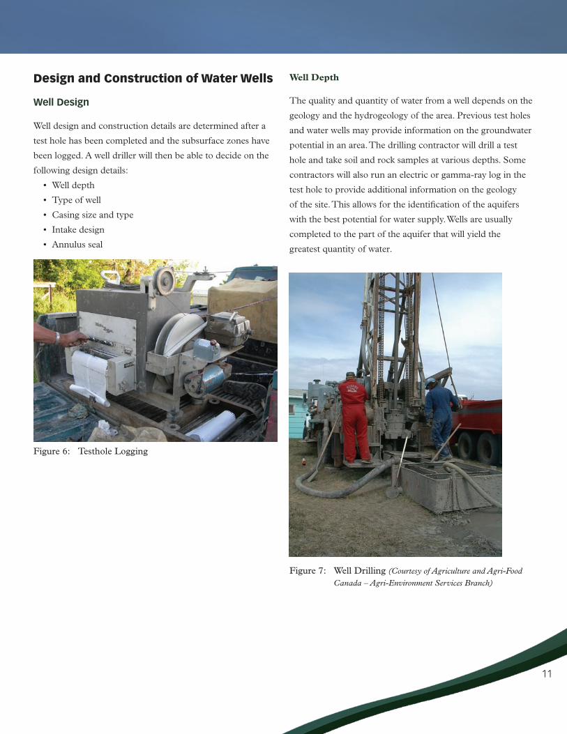
Figure 6: Testhole Logging
Well Depth
The quality and quantity of water from a well depends on the
geology and the hydrogeology of the area. Previous test holes
and water wells may provide information on the groundwater
potential in an area. The drilling contractor will drill a test
hole and take soil and rock samples at various depths. Some
contractors will also run an electric or gamma-ray log in the
test hole to provide additional information on the geology
of the site. This allows for the identification of the aquifers
with the best potential for water supply. Wells are usually
completed to the part of the aquifer that will yield the
greatest quantity of water.
Figure 7: Well Drilling (Courtesy of Agriculture and Agri-Food
Canada – Agri-Environment Services Branch)

12
Types of Wells
The two common well types in Saskatchewan are rotary
drilled and bored wells. Other wells, such as sandpoints and
hand-dug wells, are very susceptible to contamination and are
not recommended.
Rotary Drilled Wells
Rotary drilling consists of advancing the borehole by means
of a rotating bit and circulating drilling fluid or air to remove
the cuttings from the borehole. The rotary drilling method
was developed to increase drilling speeds and to reach greater
depths in most formations. Therefore, drilled wells are
usually smaller in diameter (10 – 20 cm, 4 – 8 inches), and
completed to greater depths than bored wells.
Rotary drilling has many advantages. The rigs are considered
rapid, and penetration rates are relatively high in most types
of materials. Also, well screens can be set easily as part of
the casing installation. Wells installed by rotary drilling will
generally use stainless steel screens and PVC casing.
Figure 8: Drilled Well
Bored Wells
Bored wells, or large diameter wells, are constructed using
rotary bucket augers, turned from the surface by means
of a drive shaft. This produces a cylindrical hole, inside
of which a well screen and casing can be installed. Bored
wells are usually used in shallower, low-yielding formations
for more storage capacity to better meet peak demand use
periods. This method is widely used for well construction in
Saskatchewan, especially for domestic water sources.
Bored wells are usually 46 cm to 122 cm (18 – 48 inches)
in diameter, with the most common size being 76 cm (30
inches). Generally in Saskatchewan they are limited to depths
of approximately 30.5 m (100 ft). Because bored wells
generally use shallow groundwater, they are more susceptible
to seasonal water level fluctuations.

13
Casing Size and Type
Casing is a pipe that is used to protect the borehole from
collapsing. The selection of the casing material and size is
based on the following:
• Waterquality
• Anticipatedwellyield
• Welldepth
• Cost
• Boreholediameter
• Drillingprocedure
• Regulations
The diameter of the casing should be chosen to
accommodate the pumping equipment, with enough
clearance for installation and efficient operation. Casings can
be made from steel, plastic or fibreglass, although plastic is
now more widely used because it is inexpensive and corrosion
free. Bored wells usually use galvanized steel or fibreglass. All
materials must be new and uncontaminated; therefore, no
recycled material should be used.
Figure 10: Casing Installation
Figure 11: Lowering well screens
Figure 9: Bored Well
14
Intake Design
Groundwater enters the well through either a manufactured
screen or a mechanically slotted or perforated liner. The
screen is placed adjacent to part or all of the aquifer
formation. Screens are engineered to allow the maximum
amount of water in with minimal entry of formation
sediments.
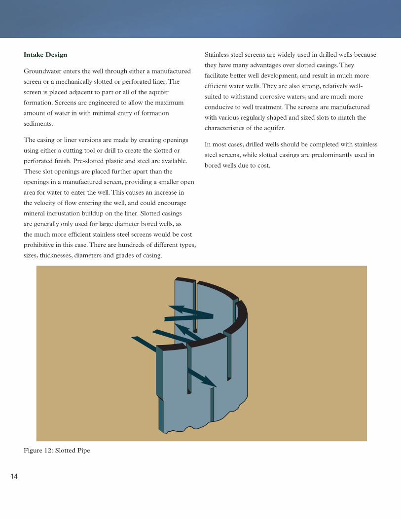
The casing or liner versions are made by creating openings
using either a cutting tool or drill to create the slotted or
perforated finish. Pre-slotted plastic and steel are available.
These slot openings are placed further apart than the
openings in a manufactured screen, providing a smaller open
area for water to enter the well. This causes an increase in
the velocity of flow entering the well, and could encourage
mineral incrustation buildup on the liner. Slotted casings
are generally only used for large diameter bored wells, as
the much more efficient stainless steel screens would be cost
prohibitive in this case. There are hundreds of different types,
sizes, thicknesses, diameters and grades of casing.
Stainless steel screens are widely used in drilled wells because
they have many advantages over slotted casings. They
facilitate better well development, and result in much more
efficient water wells. They are also strong, relatively well-
suited to withstand corrosive waters, and are much more
conducive to well treatment. The screens are manufactured
with various regularly shaped and sized slots to match the
characteristics of the aquifer.
In most cases, drilled wells should be completed with stainless
steel screens, while slotted casings are predominantly used in
bored wells due to cost.
Figure 12: Slotted Pipe

15
Slot Size Opening
The width of slot openings should be chosen to match the
grain size of the aquifer. The slot openings should be small
enough to permit easy entry of water into the well while
keeping sediment out.
The width of openings needed can differ between wells in the
same formation depending on whether the well is naturally
developed or filter packed. Aquifers with coarse-grained
materials can be developed naturally, whereas those featuring
fine-grained homogeneous materials are best developed using
a gravel pack.
In naturally developed wells, the screen slot is selected so that
approximately 60% of the aquifer material will pass through
during development. The remaining 40%, comprising the
coarsest materials, will form a natural filter pack around the
perforations or screen.
In filter packed wells, a gravel pack is placed between the
walls of the hole and the screen to provide artificial filtering.
The grain size of the gravel is selected as a function of the
grain size of the surrounding formation.
Figure 13: Slot Size

16
Total Open Area of Screen
The total open area of the screen is determined by the screen
length and diameter. The length of the screen is based on the
thickness of the aquifer, available drawdown, and the nature
of the stratification of the aquifer. The screen diameter is
dependent on the diameter of the well casing.
The open area of the screen should be chosen so that water
does not enter the well too quickly. The driller will do this
by balancing the length and slot sizes of the screen with the
desired well yield. If the speed at which water enters the well
is too high there are a number of undesirable impacts, such as
the increased occurrence of incrustation.
Placement of Intake
In virtually every aquifer, certain zones will transmit more
water than others. Thus, the intake part of the well must be
placed in the zones that will yield the greatest quantity of
water.
Annulus Seal
When constructing a well, the diameter of the borehole is
usually slightly larger than the casing being installed. The
resulting space (the annulus of the well) must be filled with
a watertight sealant such as bentonite or cement for the
entire length of the casing above the screened portion or the
sand-packed portion of the annulus. This maintains water
quality by preventing the migration of contaminants between
aquifers or from the surface.
Figure 14: Annulus Seal
17
Well Completion
After the well has been drilled and the casing is in place,
there are several procedures that the drilling contractor
must complete before the well can be used. Well completion
involves the following three processes:
• Welldevelopment
• Yieldtest
• Disinfectionofthewell
Well Development
Well development is the process where the aquifer material
around the well screen is rearranged and fine particles are
removed in order to produce a filter. This mainly concerns
the region directly adjacent to the well where aquifer
materials have been affected by the drilling fluid or disturbed
by well construction procedures. Well development increases
the movement of water from the aquifer into the well and
increases the quantity of water that the well produces.
Stainless steel screens will have significant advantages over
slotted casing during well development.
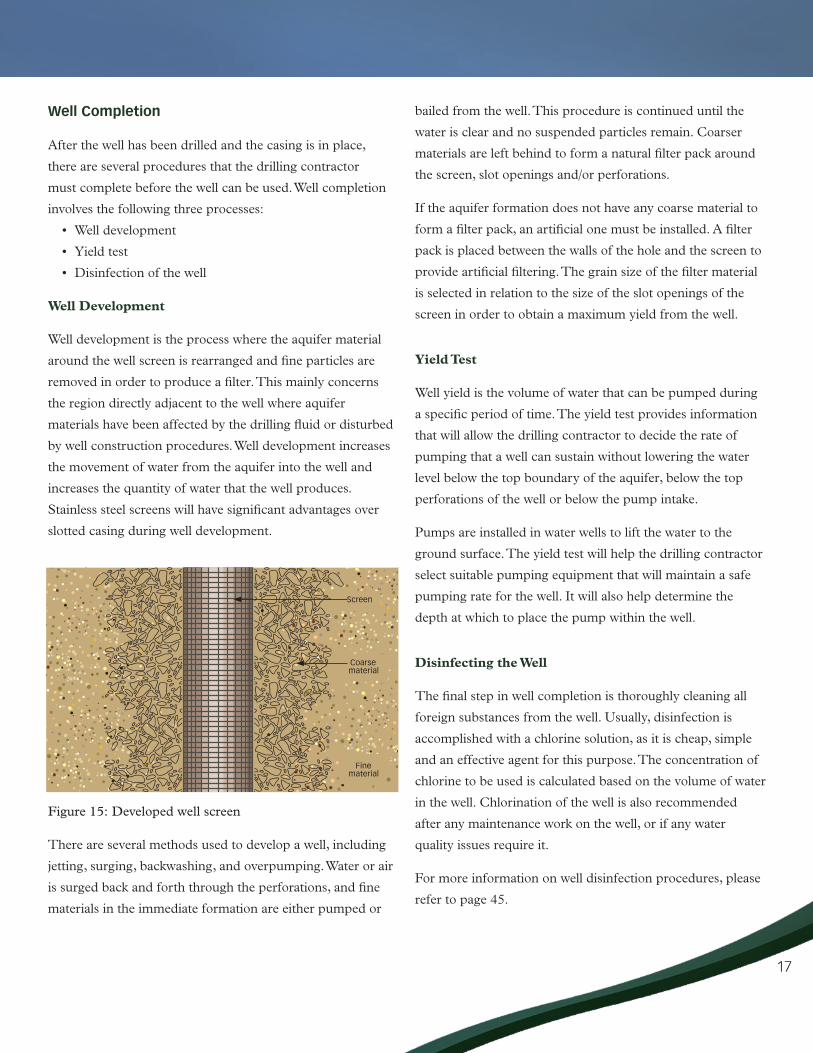
Figure 15: Developed well screen
There are several methods used to develop a well, including
jetting, surging, backwashing, and overpumping. Water or air
is surged back and forth through the perforations, and fine
materials in the immediate formation are either pumped or
bailed from the well. This procedure is continued until the
water is clear and no suspended particles remain. Coarser
materials are left behind to form a natural filter pack around
the screen, slot openings and/or perforations.
If the aquifer formation does not have any coarse material to
form a filter pack, an artificial one must be installed. A filter
pack is placed between the walls of the hole and the screen to
provide artificial filtering. The grain size of the filter material
is selected in relation to the size of the slot openings of the
screen in order to obtain a maximum yield from the well.
Yield Test
Well yield is the volume of water that can be pumped during
a specific period of time. The yield test provides information
that will allow the drilling contractor to decide the rate of
pumping that a well can sustain without lowering the water
level below the top boundary of the aquifer, below the top
perforations of the well or below the pump intake.
Pumps are installed in water wells to lift the water to the
ground surface. The yield test will help the drilling contractor
select suitable pumping equipment that will maintain a safe
pumping rate for the well. It will also help determine the
depth at which to place the pump within the well.
Disinfecting the Well
The final step in well completion is thoroughly cleaning all
foreign substances from the well. Usually, disinfection is
accomplished with a chlorine solution, as it is cheap, simple
and an effective agent for this purpose. The concentration of
chlorine to be used is calculated based on the volume of water
in the well. Chlorination of the well is also recommended
after any maintenance work on the well, or if any water
quality issues require it.
For more information on well disinfection procedures, please
refer to page 45.

18
Well Management
It is important to monitor and maintain a water well in
order to ensure adequate water supply and water quality.
If a water source is not developed or maintained properly,
it may become subject to water quality deterioration or
contamination that could ultimately yield the water unfit
for human or farm use. Taking water level measurements
and water quality measurements are important steps in
well management.
Water level Measurements
The condition of a well can be monitored through the
changes in the water level or discharge rate. A continuous
drop in the water level could indicate a deterioration of the
well structure, or a depletion of the aquifer itself.
Taking water level measurements on a regular basis will
show whether water levels have changed significantly.
Measurements should be taken with the pump both on and
off. Readings taken with the pump in operation will alert the
well owner to any problems related to the well itself, such as a
plugged intake screen. Readings taken with the pump turned
off will alert the owner to problems with the aquifer and the
quantity of water available for pumping.
Water Level Measurement Methods
There are several methods available for measuring
water levels, including:
• Diptube
• Weightedline/measuringtape
• Waterwellsounder
• Airlinemethod
Dip Tube
A dip tube can be constructed using a minimum 18 mm
(3/4 inch) plastic pipe or hose, which will be lowered into the
well to below the pumping water level. It should be secured
to the pump line with electrical tape and should have a
capped bottom with two 6 mm (1/4 inch) holes perforated
on the bottom to let water in and out, allowing it to fluctuate
identically to the water inside the well. A measuring device,
such as a weighted line or a well sounder tape, can then be
lowered inside the dip tube to measure the water level, with
no threat of getting entangled in the pumping equipment.
Figure 16: Dip Tube
19
Weighted Line/Measuring Tape
The weighted line/measuring tape device is commonly
used for measuring water levels in large diameter or shallow
wells. A weight is attached to the end of a 30.5 m (100 ft)
measuring tape or line. The last 2.5 to 3 m (8 to 10 ft) of the
tape is dried and coated with chalk before each measurement.
The tape is then lowered down the well until a part of the
chalked section is below water. A note is made on the tape
exactly at the top of the casing. The tape can then be pulled
up, and the actual depth from the top of the casing to the
water level can be determined by subtracting the wetted mark
from the mark made at the top of the casing.
Water Well Sounder
Water well sounders, or water tapes, are convenient and
accurate tools for measuring water levels. Water well
sounders can be purchased from various suppliers in the
province. Electric water well sounders can be purchased with
measurements to the closest millimetre.
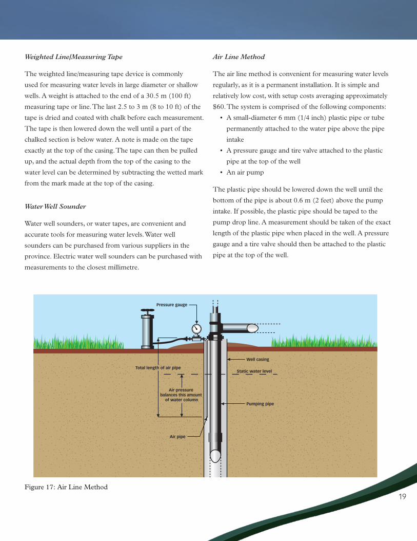
Air Line Method
The air line method is convenient for measuring water levels
regularly, as it is a permanent installation. It is simple and
relatively low cost, with setup costs averaging approximately
$60. The system is comprised of the following components:
• Asmall-diameter6mm(1/4inch)plasticpipeortube
permanently attached to the water pipe above the pipe
intake
• Apressuregaugeandtirevalveattachedtotheplastic
pipe at the top of the well
• Anairpump
The plastic pipe should be lowered down the well until the
bottom of the pipe is about 0.6 m (2 feet) above the pump
intake. If possible, the plastic pipe should be taped to the
pump drop line. A measurement should be taken of the exact
length of the plastic pipe when placed in the well. A pressure
gauge and a tire valve should then be attached to the plastic
pipe at the top of the well.
Figure 17: Air Line Method

20
A measurement should be taken of the height of water above
the lower end of the air line. This can be calculated using the
air pump and pressure gauge as follows:
1. All joints and connections should be airtight. Air should
then be pumped into the air line until the pressure
shown by the gauge levels off at a constant maximum,
indicating that all water has been forced out of the line.
2. The reading of the gauge can then be converted to a
height:
a. If the gauge measures lb/sq inch (psi), then the
reading should be multiplied by 2.31 in order to
calculate the height in feet.
b. If the gauge measures kilopascals (kPa), then the
reading should be divided by 9.8 in order to calculate
the height in metres.
3. Deduct this pressure from the known length of the air
line to determine the water level.
The air line method is based on the principle that the
air pressure required to push all of the water out of the
submerged portion of the air line will equal the water
pressure of a column of water of that same height.
When all of the water has been forced out of the line,
the pressure gauge stabilizes and indicates the original
water column length.
Interpreting Water Levels
Once water level measurements have been taken, it is
important to know how to interpret both non-pumping
(static) and pumping water levels.
Non-pumping Water Levels
The non-pumping (static) water level is the level of water
in a well that is not being affected by the withdrawal of
groundwater. In other words, it is recorded after the pump
has been shut off for an extended period of time and the
water level in the well has fully recovered.
Monitoring the non-pumping water level allows the owner to
assess whether the aquifer is sustainable at a specific pumping
rate. A continually dropping water level could be caused by
the overpumping of the well. In this case, the amount of water
being taken from the well should be reduced. Further water
level measurements should then be taken to see if the water
level recovers.
Changes in water level could also be caused by seasonal
fluctuations. For example, in shallower wells water levels
are usually highest in June or July and gradually decline
throughout the fall and winter.
If there is no significant change in the static water level, then
full recharge of the aquifer is occurring at the same rate as
water is being pumped from the well and sustainable water
use is taking place.
Pumping Water Level
The pumping water level is the level at which water stands
when the pump is in operation. Measurements should be
taken when the pump has been in operation for a consistent
period of time and there has been significant water use. For
example, readings should always be taken when the pump
has been in operation for two hours. This will allow for the
comparison of results.
A drop in the pumping water level of a well, when there is
no drop in the non-pumping level, indicates a problem with
the well structure. This could include plugging of the screen
(or slotted casing), bacterial growth, or incrustation that is
diminishing the efficiency of the well. Conversely, a lowered
discharge rate of the pump with an increase in the pumping
water level would suggest a problem with the pump.
Even when the pumping water level remains relatively stable,
regular maintenance procedures, such as shock chlorination,
should be performed in order to maintain well efficiency.

21
Water Quality Measurements
The Saskatchewan Ministry of Environment sets quality
objectives and monitors testing programs for municipal water
supplies based on Health Canada guidelines, but there are no
legal testing requirements for private wells. It is therefore up
to the well owner to monitor the quality of their water. Well
water should be tested for water quality initially after well
construction and prior to being used, as well as on an at least
yearly basis. For a list of provincial water quality guidelines
and objectives please refer to page 48.
In addition to regular water quality testing, there are certain
times when it is prudent or advisable to perform extra tests.
These include:
• Duringrunofforafteraheavyrainwherewatermay
affect the well.
• Afterworkhasbeendoneonthewell.
• Afterchangesinnearbylanduse,suchaslandfillactivity,
road salting, installation or repair of septic systems, or
road construction.
• Afterchangesaredetectedinthecolour,smellor
appearance of the water.
• Whenthereisanewborninthehouse.
Ground and surface water supplies in Saskatchewan are often
of poor quality and require some form of treatment to make
them safe and aesthetically acceptable. Although some water
quality characteristics can be determined by the way the
water looks, tastes or smells, other properties that cannot be
detected by these methods should also be considered. Even
if water looks and tastes fine, it still might not be safe for
consumption. For this reason, analysis, including bacterial,
nitrate and trace metals testing, should be performed by an
accredited water analysis laboratory. Tests for bacteria and
nitrate should be done routinely (at least annually), while
tests for trace metals can be done less frequently. Please
refer to page 56 for contact information for accredited
water analysis laboratories in Saskatchewan.
Figure 18: Pumping Water Level
22
Method of Collection
In order to ensure a representative water sample, proper
collection procedures must be followed. It is recommended
that the well owner contact the laboratory that will examine
the sample for information on collection and delivery
procedures. The well owner should also consider:
• Thelengthoftimethewellispumpedpriortosampling.
• Howthesampleisstored.
• Thelengthoftimeitwilltakeforthesampletobe
delivered to the laboratory.
The sample should also be collected as close to the wellhead
as possible to avoid any effect the water treatment or
distribution systems may have on the water quality results.
Bacterial and Nitrate Analysis
It is important to determine if bacterial or nitrate
contamination is present in a well, as these are the most
commonly encountered forms of contamination. The
standard bacteriological tests for private wells are called the
Total Coliform (TC) test and the E.Coli (EC) test. When
running bacteriological tests, the Saskatchewan Ministry of
Health’s Disease Control Laboratory can also test for nitrate
level in the water, if requested. If another lab is performing
the test, it is prudent to ensure that nitrate is also included in
the test.
Chemical Analysis
A chemical analysis tests for the most common ions and trace
metals found in water, such as sodium and sulfates.
Questionsrelatingtohumanhealthshouldbedirectedto
the local Health Region. Please refer to page 54 for contact
information.
Well Maintenance
Iron and sulfate-reducing bacteria are a widespread problem
for many water wells in Saskatchewan. As they are not
detrimental to human health, water quality guidelines for iron
and sulfate-reducing bacteria are set on the basis of taste and
appearance.
Shock chlorination is a cheap, simple and effective
procedure used to control bacteria in water well systems.
Shock chlorination is recommended as part of semi-annual
maintenance to control iron and sulfate-reducing bacteria.
Identifying Iron and sulfate-Reducing bacteria
Bacteria Growth
Bacteria growth will coat the inside of the well casing, water
piping and pumping equipment, causing a decrease in well
yield or restricted water flow in distribution lines. An easy
way to verify that a well or water system is being affected
by iron bacteria is to examine the inside surface of the toilet
flush tank. If a greasy, slimy substance can be observed, then
iron bacteria are most likely present.
Staining Problems
Discolorations of water are often caused by the presence
of iron. When the level of iron within the water exceeds the
water quality guideline, red, brown, or yellow staining of
laundry, dishes or fixtures are often observed.
Taste and Odour
The presence of bacteria can cause the water to have
an offensive taste or odour. For example, the presence of
sulfate-reducing bacteria can cause a rotten egg or sulfur
odour in water.
23
Regular Disinfection
General maintenance of a groundwater supply should include
semi-annual chlorine disinfection. For information on well
disinfection procedures, please refer to page 45.
Common Well Problems
Problems with a well can result from many causes, including
improper well design and completion, equipment failure,
incrustation, corrosion and depletion of the aquifer. These
problems could lead to decreases in well yield and water
quality. By properly identifying a specific well problem,
appropriate treatment or maintenance procedures can be
carried out and more costly solutions, such as drilling a new
well, can be avoided.
Improper Well Design and Construction
When designing or constructing a new water well, a drilling
contractor must make decisions that will ultimately affect
the quality and yield of water from the well. These decisions
include the location and depth of the well, the type and
size of casing and screen, the use of a gravel pack, and the
location of the pump in the well. Poor choices could result in
problems with contamination, sediment in the water or with
well yield. If it is suspected that the well is of poor design or
construction, a drilling contractor should be contacted.
Incomplete Well Development
Proper well development will insure that all drilling fluid
and borehole cuttings are removed, allowing water to freely
enter the well. If this procedure is not properly carried out,
problems with sediment in the water or low well yield may
occur. Therefore, the driller must ensure that the well is
properly developed.
borehole Instability
Borehole stability problems can result from damaged casings
and screens, borehole wall collapse, corrosion, or excessive
water velocities in the well. To avoid this type of problem, it
is necessary to select appropriate materials during the well
design and construction stage. A drilling contractor should
be contacted to determine whether repair of the well is
economically feasible. If it is not, the well should be properly
decommissioned and a new well should be drilled.
sand Pumping
In older wells, sand pumping can be caused by corrosion
slowly eating away at the surface metal of the well casing.
Other possible reasons for sand pumping include improper
slot size, improper well level, overpumping, or casing
separation. A drilling contractor should be consulted to
determine the reason for the sand pumping.
Incrustation
When water is pumped from a well, changes in pressure
and temperature occur. This provides ideal conditions for
minerals to be deposited within the gravel pack around the
screen or upon surfaces of the screen, casing, or pump. These
deposits can reduce water passage and decrease the yield of
the well.

24
There are three major forms of incrustation:
• Incrustationfromcalciumandmagnesiumcarbonates.
• Incrustationfromironandmanganese.
• Incrustationcausedbyslime-producingironbacteria
(biofouling).
Well owners can take preventative measures to help prevent
incrustation. Regular shock chlorination can help control
biofouling, and reducing pumping rates can help control
mineral incrustation.
Carbonate
Incrustations can result from the precipitation of carbonates,
principally calcium, from groundwater near the well screen.
Other substances, such as aluminum silicates and iron
compounds, can also add to the deposits and reduce the flow
of water.
Iron and Manganese
Discolorations of water are often caused by the presence of
iron and/or manganese. When there is an excess of iron, red,
brown, or yellow staining of laundry, dishes and fixtures can
be found. Manganese acts in a similar fashion, but causes a
brown-black stain.
Biofouling
Biofouling is the accumulation of slime-producing bacteria.
This accumulation can prevent water from moving into
the well at the desired rate. Common effects of biofouling
include clogging, corrosion, an undesirable odour and
taste, bioaccumulation, and biodegradation activities. With
biofouling, a slime growth can normally be observed on
surfaces that are in contact with the water, such as the inside
of the toilet flush tank.
Plugging of screen and surrounding formation
The clogging of well screen openings with aquifer particles
is a relatively common well problem, and can result in a
lowered yield from the well. It can often be observed in wells
that have been improperly developed or have poorly designed
filter packs or screens. It can also be due to pumping at rates
greater than those for which the well was designed. For this
reason, the driller’s recommended pumping rate should not
be exceeded. This plugging of the screen and surrounding
formation can also be observed in older, regularly used wells.
Fine particles slowly move into the area around the screen
and can decrease the specific capacity of the well. For a
plugged screen and surrounding formation, have a drilling
contractor redevelop the well.
Corrosion
Corrosion can cause the enlargement of the screen slots or
the development of holes in the well casing. This can result in
sand pumping. To eliminate corrosion, contractors may use
materials such as plastic and fibreglass casings or stainless
steel screens that are resistive to corrosion in the construction
of new wells. Plastic liners may be installed in old steel wells
to prolong the life of the well.
failures linked to the Resource
A decrease in a well’s yield might not be due to a problem
with the well structure itself, but might be linked to external
factors. For example, in a period of drought the groundwater
levels will lower, and will therefore bring about a drop in the
pumping water level. Taking regular measurements of static
water levels will help to identify possible problems related to
the aquifer and will help avoid the possibility of overpumping.

25
There are numerous preventative measures that a well
owner can take to help protect their well from possible
contamination. If water becomes contaminated, it can affect
the health of people and livestock. It may also affect the
quality of the water in nearby lakes, streams, dugouts, or
other wells, impacting neighbouring water users. It is much
easier and less expensive to prevent contamination than to
clean it up. Treating contaminated water, drilling a new well,
or getting water from another source are all inconvenient and
expensive options.
Wellhead protection against contamination is important for all
well owners. Wells can provide a direct route for contaminants
to reach groundwater. It is therefore imperative that wells be
constructed in a way that protects the water resource and
inhibits the downward movement of contaminants.
Well owners should pay especially close attention to
protecting the aquifer from contamination if it is naturally
vulnerable. Where water can infiltrate below the root zone,
there is a risk of pollution from dissolved chemicals in the
water. The risk is increased when the aquifer is shallow,
and where there are coarse textured soils such as sands and
loamy soils that have large pore spaces which allow water to
percolate through quickly.
Well Head Protection
Proper Well siting
There is a greater risk of water contamination if the well
is drilled in close proximity to potential contamination
sources such as livestock yards, septic systems, and manure
storage facilities.
Proper Well Construction
The following design considerations can help prevent the
contamination of a well:
• Apropercasingandannulussealmaintainswaterquality
by preventing the movement of contaminants between
aquifers and from the ground surface.
• Thetopofthewellcasingshouldbeapproximately0.6-
0.9 m (2-3 ft) above ground level, and the area around
the well should be built up with good clay soil and sloped
away from the well so that surface water will drain away
from the well in all directions.
• Aventedwatertightwelllidshouldbeinstalledto
prevent water and bugs or other creatures from entering
the well.
C H a P T e R 3
Protecting Wells from Contamination
Figure 19: Well Cap
26
Well Contamination During Maintenance
Water can become contaminated when equipment is placed
in the well without being properly disinfected. This can occur
during the construction of a new well or during maintenance
when piping or equipment is laid on the ground.
Improperly Decommissioned Wells
There are several ways that abandoned wells and improperly
decommissioned wells may allow for the contamination
of aquifers. They can act as a pathway for surface runoff
to directly enter the aquifer. They can also permit cross-
contamination of different aquifers along the length of the
borehole. Nearby wells that are completed in the same aquifer
may also eventually become contaminated.
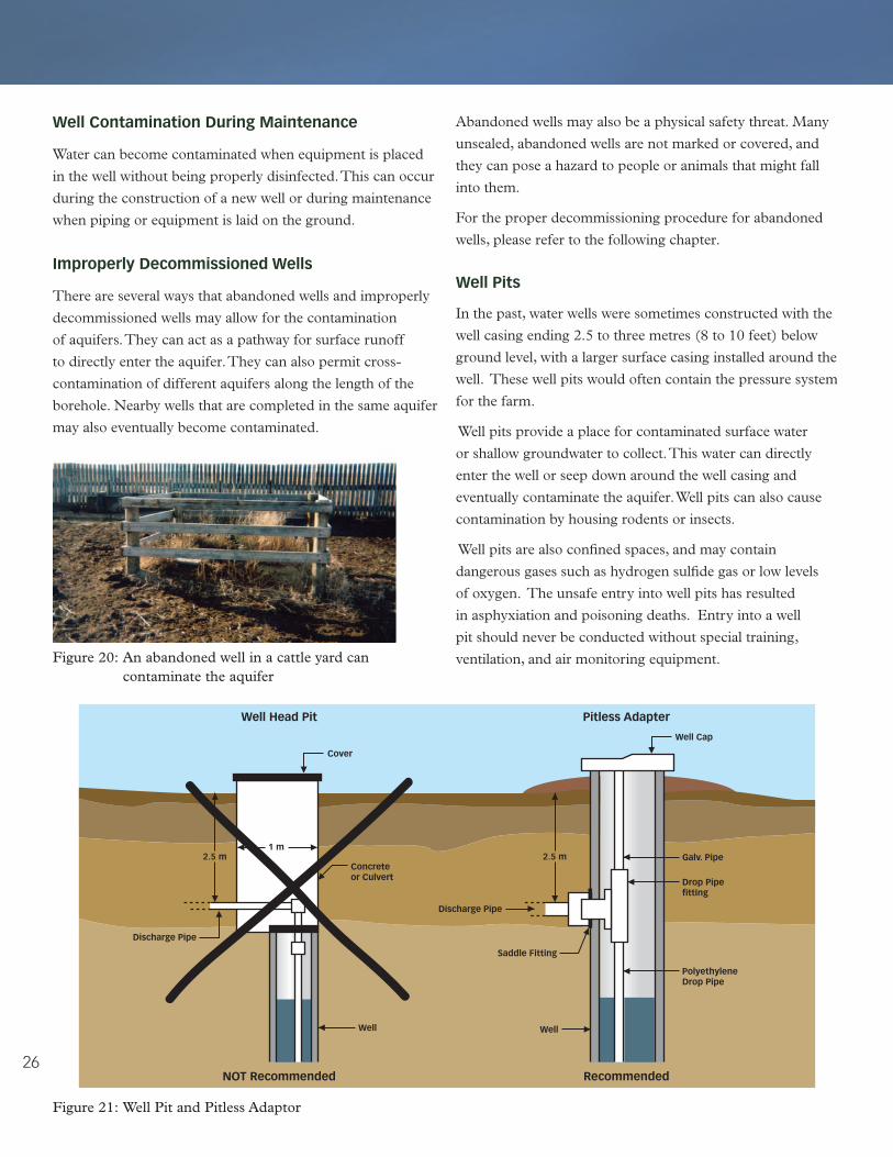
Figure 20: An abandoned well in a cattle yard can contaminate the aquifer
Abandoned wells may also be a physical safety threat. Many
unsealed, abandoned wells are not marked or covered, and
they can pose a hazard to people or animals that might fall
into them.
For the proper decommissioning procedure for abandoned
wells, please refer to the following chapter.
Well Pits
In the past, water wells were sometimes constructed with the
well casing ending 2.5 to three metres (8 to 10 feet) below
ground level, with a larger surface casing installed around the
well. These well pits would often contain the pressure system
for the farm.
Well pits provide a place for contaminated surface water
or shallow groundwater to collect. This water can directly
enter the well or seep down around the well casing and
eventually contaminate the aquifer. Well pits can also cause
contamination by housing rodents or insects.
Well pits are also confined spaces, and may contain
dangerous gases such as hydrogen sulfide gas or low levels
of oxygen. The unsafe entry into well pits has resulted
in asphyxiation and poisoning deaths. Entry into a well
pit should never be conducted without special training,
ventilation, and air monitoring equipment.
Figure 21: Well Pit and Pitless Adaptor

27
Because of the unacceptable risks presented by well pits, they
should never be used. A pitless adaptor provides a sanitary
connection between the well and the pressure system, and
avoids the hazards and contamination issues of a well pit.
Where well pits are currently used, the well casing should be
extended above ground and the well should be connected to
the distribution system with a pitless adaptor, allowing the
well pit to be decommissioned.
Water Hydrants Installed in a Well or Well Pit
Water hydrants prevent freezing by draining water back
down the well whenever they are shut off. In other words, the
contents of the standpipe and hose are siphoned back into
the well. Water hydrants can cause back siphoning that can
draw contaminated water back down the well. For this reason,
hydrants should never be completed in, or immediately
adjacent to, a well.
Figure 23: Water Hydrant
Figure 22: Water Hydrant

28
Aquifer Protection
Some aquifers are more susceptible to contamination
than others, especially those located at shallow depths and
overlaid by coarse textured soils. Although the susceptibility
to contamination for each well can only be judged on an
individual basis, general attempts should always be made to
maximize the distance between contamination sources and
the well. The well should also be upslope from these sources,
and in a well-drained location.
onsite Wastewater systems
Onsite sewage systems can include holding tanks and
septic tanks (which by themselves are a very low risk to
groundwater supplies), chamber systems, absorption fields,
mounds, jet type disposals, lagoons and package treatment
systems. The Province of Saskatchewan has regulations to
control the proper construction of onsite wastewater systems.
All such systems (septic tanks and sewage disposal options)
require a permit from the Health Region for a private sewage
works under The Plumbing and Drainage Regulations and to
be designed and installed according to The Saskatchewan
Onsite Wastewater Disposal Guide. The system should also
be maintained and operated within the design parameters,
and the treated sewage should be disposed of properly. For
an average household with a properly sized septic tank, the
septic tank should be inspected for required cleaning at
intervals of no more than two years to determine scum and
sludge accumulation. It should also be ensured that the tank
is not cracked or broken, and that the pump is functioning
properly.
Figure 24: Septic System Contamination

29
fuel storage Tanks
Contamination of groundwater by hydrocarbons from fuel
storage tanks is a significant problem. To avoid a spill or leak,
it is important to have a properly installed, approved tank that
will resist corrosion. Fuel storage tank dispensers are required
to meet legislated requirements and avoid accidental spills
due to overfilling or siphoning. Only approved dispensers
[e.g. by the Underwriters’ Laboratory of Canada (ULC) or
the Canadian Standards Association (CSA)] are acceptable.
All fuel must be pumped in such a manner as to meet
legislated requirements and to avoid unwanted dispensing
of fuel.
Tanks should be monitored for leakage by keeping
measurements of the amount of fuel used and comparing
this to the amount purchased. A spill or leak can occur in
large quantities due to a tank rupture, or in small quantities
due to pinhole leaks. If not contained, leaks can cause serious
damage to groundwater quality. A dike can capture any spills
or leaks from above-ground tanks. These spills should be
cleaned up immediately. Above-ground fuel storage tanks are
considered more desirable than underground tanks, as they
are easier to monitor for leaks.
Pesticide Contamination
Pesticide is a broad term that refers to substances such as
insecticides, rodenticides, fungicides, and herbicides used to
control insects, rodents, fungal disease, and weeds. Pesticide
contamination usually occurs when pesticides are mishandled
in the area surrounding the well. Therefore, pesticides should
be handled carefully, and should not be mixed or stored
near a well. A safe storage area should be used, and pesticide
containers should be emptied and the rinsate disposed
of safely.
Manure and fertilizer Contamination
Fertilizer or manure that is applied to agricultural land in
excess of the crops’ nutrient requirements can lead to nitrates
being leached into groundwater. Regularly testing soil and
manure can help maintain a balance between the nutrient
requirements of the crops and the nutrient content of the
manure or fertilizer.
Fertilizers should be handled carefully and stored in areas
that meet all safety requirements. Storage facilities for manure
should be large enough to safely hold all of the manure that
is produced and should be checked regularly for leaks
and damage.

30
Improper storage of silage
Silage is an important source of feed for livestock, but if
it is improperly handled or stored, liquid or seepage may
escape from the storage site. This seepage can contain high
concentrations of nutrients and acid and can negatively affect
groundwater quality. Therefore, silage should be stored at
an appropriate moisture level to minimize seepage, and all
parts of the silage storage, including the lining, should be in
good condition.
livestock Yards
Livestock yards include feedlots, cow-calf facilities, livestock
handling facilities, stockyards, and assembly stations. Manure
contains nutrients and microorganisms that could be a danger
to groundwater quality. The livestock yard should be located
a significant distance from nearby wells, and manure and
all runoff from the facility should be collected and stored to
avoid groundwater contamination. Under The Agricultural
Operations Act, certain types of intensive livestock operations
are required to obtain provincial approval of waste storage,
manure management and dead animal disposal plans to
ensure water protection.
Figure 25: Intensive Livestock Operation
Disposal of farm Wastes
Farm wastes include dead livestock, animal health care
products, packaging, old farm buildings, and worn-out
equipment or machinery. Farm wastes may adversely affect
groundwater quality if they are stored or disposed of in the
wrong way. Whenever possible, all material or equipment
should be recycled. Organic material, including leaves
and dead animals or portions of dead animals, should be
composted. Intensive livestock operations should have a
dead animal disposal plan which has been approved by the
Saskatchewan Ministry of Agriculture. All other material
should be taken to a licensed landfill site.

31
Abandoned wells are wells that are no longer in use. Over the
years, many wells and test holes around homes and farms
throughout the province have been abandoned without being
properly sealed and decommissioned. Abandoned wells or
improperly decommissioned wells can pose a serious threat
to groundwater quality and can also be a safety hazard.
Therefore, all abandoned wells should be properly plugged
to prevent contamination and to eliminate any safety hazards.
When a replacement water well is drilled, the old well should
be plugged.
Abandoned wells:
• Canallowsurfacerunofftodirectlyenteranaquifer,
contaminating the aquifer and potentially contaminating
nearby wells.
• Canpermitcross-contaminationofdifferentaquifers
encountered by the well bore.
• Canbeaphysicalsafetythreat,astheyareoftennot
marked or covered, and can pose a hazard to people
or animals that might fall into them.
• Canbealiabilityproblemifthewellcontaminates
neighbouring wells, or if the abandoned well still exists at
the time of property resale.
Figure 26: Bull in Well
C H a P T e R 4
abandoned Wells
Figure 27: Contamination from an Abandoned Well

32
The same negative impacts can occur from test holes. For this
reason, proper abandonment of test holes is also critical to the
protection of groundwater quality.
When a well is abandoned after the date of completion, the
owner is immediately responsible for filling and sealing the
well with suitable uncontaminated material in a manner
as to prevent the vertical movement of water in the well.
It is recommended that a well owner hire a registered
drilling contractor to ensure that the well is properly
decommissioned. A well contractor will have access to
the necessary equipment, as well as an understanding of
correct abandonment materials and procedures. Unless the
right materials are used and are properly placed in the well,
the well will be poorly sealed and may continue to allow
contaminants to reach the groundwater.
Decommissioning abandoned Wells
Procedures
Well decommissioning procedures vary, depending primarily
on well construction, hydrogeology and the geology of
the site. One set of well decommissioning procedures is
not suitable for all wells. The following decommissioning
procedures should only be used as general guidelines. Site-
specific conditions will dictate the exact procedures that
should be followed to properly decommission the well.
Figure 28: Abandoned well
Decommissioning procedures:
• Removal of well equipment (pumps, drop pipe,
wiring, etc.)
• Well Characterization – the depth, diameter and
non-pumping (static) water level of the well should
be recorded. This information is used to calculate the
amount of materials required to decommission the well.
It can also be used to compare the original depth to the
current depth of the well and determine if a portion of
the well has collapsed or if an obstruction exists within
the well column. If an obstruction does occur within
the well, it should be removed prior to sealing the well
whenever possible.
• Disinfection – enough chlorine should be added
to bring the standing water in the well to a chlorine
concentration of 250 mg/L. The amount of chlorine to
be added will depend on the casing size and the amount
of water in the well. The table on the following page will
help determine the quantity of chlorine that should be
added to achieve a concentration of 250 mg/L when
using either 12% sodium hypochlorite, 70% granular
calcium hypochlorite, or 5.25% household bleach. This
chlorinated water is to be left in the well.
• Remove casing – the casing should be removed prior
to plugging the well whenever possible, but only if the
integrity of the borehole will not be affected. Removing
the casing in domestic wells that have been in place for
a substantial period of time is often very difficult. Any
casing that is left in place should be cut off three meters
(9.85 ft) below ground surface after the well is sealed.
• Filling and sealing – the most preferred materials for
sealing wells are low permeability materials that prevent
the vertical movement of water. Generally the best
product for this purpose is a manufactured bentonite
product (chips, pellets or grout). However, in some
cases it may be acceptable to use a combination of
bentonite, clay and granular material. The effectiveness
of well decommissioning in maintaining the quality of
groundwater is determined by the placement of these
low permeable materials in key portions of the well.
The table on page 33 provides volume calculations
for filling the well.
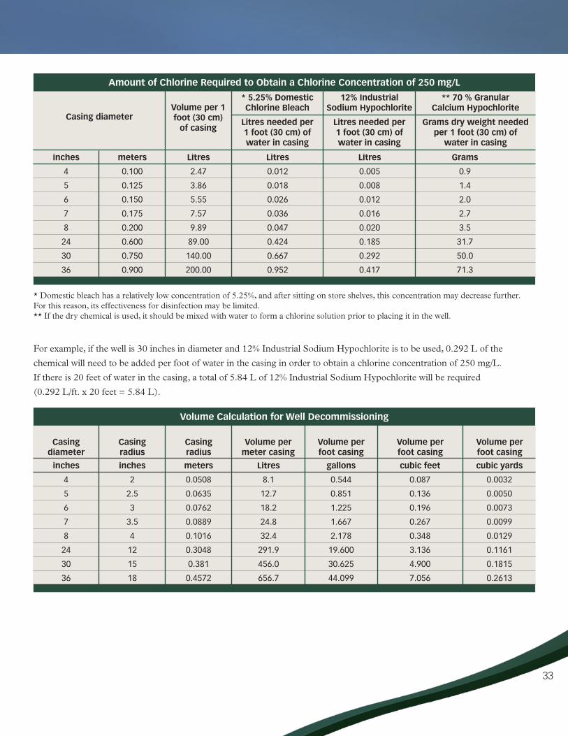
33
* Domestic bleach has a relatively low concentration of 5.25%, and after sitting on store shelves, this concentration may decrease further. For this reason, its effectiveness for disinfection may be limited.** If the dry chemical is used, it should be mixed with water to form a chlorine solution prior to placing it in the well.
For example, if the well is 30 inches in diameter and 12% Industrial Sodium Hypochlorite is to be used, 0.292 L of the
chemical will need to be added per foot of water in the casing in order to obtain a chlorine concentration of 250 mg/L.
If there is 20 feet of water in the casing, a total of 5.84 L of 12% Industrial Sodium Hypochlorite will be required
(0.292 L/ft. x 20 feet = 5.84 L).
amount of Chlorine Required to obtain a Chlorine Concentration of 250 mg/l
inches
4
5
6
7
8
24
30
36
Casing diameter
meters
0.100
0.125
0.150
0.175
0.200
0.600
0.750
0.900
litres
2.47
3.86
5.55
7.57
9.89
89.00
140.00
200.00
Volume per 1 foot (30 cm)
of casing
litres
0.012
0.018
0.026
0.036
0.047
0.424
0.667
0.952
* 5.25% Domestic Chlorine bleach
litres needed per 1 foot (30 cm) of water in casing
Volume Calculation for Well Decommissioning
inches
4
5
6
7
8
24
30
36
Casingdiameter
inches
2
2.5
3
3.5
4
12
15
18
Casing radius
meters
0.0508
0.0635
0.0762
0.0889
0.1016
0.3048
0.381
0.4572
Casingradius
litres
8.1
12.7
18.2
24.8
32.4
291.9
456.0
656.7
Volume permeter casing
gallons
0.544
0.851
1.225
1.667
2.178
19.600
30.625
44.099
Volume perfoot casing
cubic feet
0.087
0.136
0.196
0.267
0.348
3.136
4.900
7.056
Volume perfoot casing
cubic yards
0.0032
0.0050
0.0073
0.0099
0.0129
0.1161
0.1815
0.2613
Volume perfoot casing
litres
0.005
0.008
0.012
0.016
0.020
0.185
0.292
0.417
12% Industrial sodium Hypochlorite
litres needed per 1 foot (30 cm) of water in casing
Grams
0.9
1.4
2.0
2.7
3.5
31.7
50.0
71.3
** 70 % Granular Calcium Hypochlorite
Grams dry weight needed per 1 foot (30 cm) of
water in casing

34
Small Diameter Wells (drilled)
Small diameter wells should be decommissioned with a grout
seal. The grout must be introduced at the bottom of the well
and placed progressively upwards to ground surface. The use
of a grout pump and tremie pipe is the preferred method for
placing the grout. This will ensure the positive displacement
of water in the well and minimize dilution or separation of the
grout. The tremie pipe should be removed after the well has
been grouted.
Large Diameter Wells (bored)
These wells are usually 0.3 meters (12 in.) to 1.2 meters (48
in.) in diameter and less than 30 meters deep.
A 0.3-meter (12 in.) layer of bentonite chips/pellets should
be placed at the bottom of the well. The remainder of the well
should be backfilled to a depth 3 meters (120 in.) below the
ground surface with layers of uncontaminated coarse sand/
gravel not more than 3 meters (120 in.) thick, with a 0.15
meter (6 in.) layer of bentonite chips between backfill layers.
Figure 30: Filling the well with uncontaminated coarse sand or gravel
Figure 29: Pumped Method for Well Abandonment

35
• Remove casing and capping – casing that was left
in place before sealing the well should be removed
to a depth 3 meters (120 in.) below ground surface.
The excavation should be backfilled with local
uncontaminated clay, compacted and mounded to
prevent water from ponding near the abandoned
well site.
Flowing wells have unique characteristics and should only be
decommissioned by an experienced water well contractor.
The effectiveness of the well decommissioning procedures
in protecting groundwater from surface contamination is
primarily determined by the method used to decommission
the well and the materials used to seal the well. Exact
procedures may differ for each circumstance, which is why it is
important that the person responsible for performing the well
decommissioning be knowledgeable about well construction
practices and good groundwater protection principles.
Figure 31: Removal of well casing
Figure 32: Well decommissioning for large diameter wells

36
We hope that this guide has provided you with useful information about groundwater and water well management. For
assistance with any questions or concerns that were not addressed in this document, please see the contact information on
page 52 for experts on groundwater resources, well siting and management, water quality, and well decommissioning.
C o n C l U s I o n

37

38

39
Drilling Contractors
Choosing a Drilling Contractor
All drilling contractors in Saskatchewan are required to
register their drilling rigs before they operate a machine for
the purpose of obtaining groundwater or scientific data on
groundwater. The Saskatchewan Watershed Authority can be
contacted for an updated list of registered contractors and
drilling rigs (please refer to page 55 for contact information).
It is beneficial to contact numerous drillers in order to get a
comparison of quotes. It is also advisable to hire a contractor
who is familiar with the drilling conditions in the area.
Water Well Drilling agreements
Water well drilling is a costly investment, and therefore a
water well drilling agreement should be drawn up prior to the
well being drilled. This will prevent any misunderstandings
between the well owner and the drilling contractor and will
clearly define the services, materials and costs involved in the
drilling process. Agreements should cover:
• Allcostsofdrilling/wellconstruction.
• Startingdateandcompletiondate.
• Loggingoftestholeandsubmissionofdriller’sreport.
• Maximumdepthofwellconstruction.
• Typeofwellconnectiondesired(ie.pitlessadaptor).
• Desiredwellyieldandacceptablewaterquality.
• Controlofflowingwell,ifencountered.
• Detailsaboutwellconstructionmaterialssuchas:
° type and diameter of well casing.
° type and diameter of well screen.
° type of annulus or casing seal.
• Developmentofwell.
• Yieldtest.
• Disinfection.
• Installationofpump.
• Equippingthewellwithasanitarywellcap.
• Guarantees.
The following pages provide an example of a water well
drilling agreement form.
a P P e n D I x

40
Water Well Drilling agreement form
Identification
Planning of Water System
Water Sources
Water Quality Requirements
1. Well owner
Address
2. Drilling contractor
Address
3. Proposed starting date
Proposed completion date
4. Groundwater supply options based on existing records*
* A drilling contractor and well owner should research groundwater information on local wells to determine possible groundwater supply options. Information is available from the Saskatchewan Watershed Authority.
5. Proposed well use: Household Livestock Irrigation
6. Desiredwaterquality* On-sitetests:
Total dissolved solids mg/L Iron mg/L
Hardness mg/L pH
* Water quality is a very important consideration for all potential water uses. Drilling contractors can determine rough estimates for some parameters, such as total dissolved solids, iron, hardness and pH. However, only accredited water analysis laboratories can provide reliable results. These results will establish whether water treatment equipment may be needed.

41
Water Quantity Requirements
Well Site
Design and Construction of Water Well
Well Design
7. Desired yield* L/s (gpm) Min. acceptable yield L/s (gpm)
* The desired yield is the flow rate of water, either in litres per second (L/s) or gallons per minute (gpm), from a well. The desired yield can be determined by referring to the Sizing the Water Supply section in Chapter 2 of this publication. In some areas, aquifers are slow yielding, and the desired minimum yield might not be available. In this case, the desired yield should be stated as the normal yield for the area. It is important to establish a minimum yield of water desired so that the well is considered an economically feasible investment.
8. Locationofwell: Qtr Sec Twp Rge
W of Meridian Lot Block Plan
9. Maximum desired depth* m (ft.)
10. Type of drilling
11. Diameter of hole**
12. Flowing well control***
13. Well connection
14. Formation logging procedure****
15. Annulus or casing seal
16. Artificial filter pack*****
* A maximum desired depth should be established prior to drilling the well. This will depend on the known depths of productive aquifers and their respective water qualities. Personal finances are also a factor when determining the maximum desired well depth.** The type of well that is drilled will help determine the diameter of the hole. Drilled wells are usually 10 –20 cm (4 – 8 inches) in diameter, and bored wells are usually 46 – 122 cm (18 – 48 inches) in diameter*** If a flowing well is anticipated, sufficient surface casing should be set and cemented, and a control device that will allow the flow to be controlled and shut off should be added. **** Well drillers will perform various logging procedures to identify the aquifers with the best potential for water supply. These can include descriptive logging, electric logging, or gamma-ray logging.***** In the case where the aquifer has a relatively uniform grain size, an artificial filter pack may be used.

42
Material
Well Completion
Well Development
Yield Testing
Disinfection
17. Casing material
Inside diameter Weight per m (ft.) Wall thickness
18. Well cover Distance from top of casing to ground surface
19. Liner material
Insider diameter Weight per m (ft.) Wall thickness
20. Screen
Manufacturer Material
Length Nominal diameter
21. Welldevelopmentmethod: Backwashing Jetting Surging
Bailing Heavy pumping
22. Yield testing duration* (hours)
* A drilling contractor will perform a yield test in order to determine the most suitable pumping equipment for the well. The test should also provide the following information that can be used to monitor future well performance:
i. Non-pumping (static) water level.ii. Water removal rate in L/s (gpm).iii. Depth to the pumping water level at one or more constant pumping rates (drawdown).iv. The length of time the well is pumped at each rate.v. The recovery of the water level over a two-hour period or until 90% recovery of the non-pumping water level is reached.
23. Disinfection*
* The well and pumping equipment should be disinfected. The concentration of chlorine to be used is calculated based on the volume of water that is in the well. The concentration must be left in the well for at least 12 hours to ensure any bacteria present are destroyed.

43
Well Completion
Costs
Total
Guarantee
24. Well head finishing*
* Well head finishing includes the clean up and removal of any mud, aquifer debris, and material scraps.
36. Total costs
37. Payment schedule
38. Guarantee
25. Test holes per metre (ft.)
26. Reaming per metre (ft.)
27. Drilling/boring per metre (ft.)
28. Casing per metre (ft.)
29. Liner per metre (ft.)
30. Screen
31. Filter pack
32. Development
33. Labour per hour
34. Water testing
35. Reclamation of unused well

44
Water Well Drilling Reports
Driller’s Report
Within 30 days following the completion of the drilling of the
well, the drilling contractor must submit a driller’s report to
the Saskatchewan Watershed Authority.
Electric and Other Logs
If the drilling contractor runs an electric log or other log
on a test hole or well, the driller must submit a copy to the
Saskatchewan Watershed Authority within 30 days following
the completion of the logging.
45
Chlorine Disinfection Procedures
Disinfection is routinely used to control bacteria in wells
and is applied as part of a start-up procedure for newly
constructed wells and should be used as semi-annual
maintenance for existing wells. Disinfection should also be
performed in the event of contamination (e.g. flooding or
unacceptable levels of bacterial growth).
Well disinfection can be performed by two methods: low
or high level chlorine disinfection. High level chlorine
disinfection is the preferred option. However, if the proper
equipment (e.g. a 1,360 litre tank) is not available then low
level disinfection may be adequate.
Until the disinfection procedure has eliminated the bacterial
contamination, an alternate source of safe water should be
used or the water should be boiled for one minute, at a rolling
boil, before use. In addition, if possible identify and eliminate
the source of contamination.
High level Chlorine Well Disinfection
(shock Disinfection)
Materials Required
• Acleanwatertankwithaholdingcapacityofatleast
1,360 litres (300 gallons).
•Gardenhose.
•20litresofindustrialstrengthchlorine(12%sodium
hypochlorite) – available from any chemical dealer, water
treatment supplier, or dairy supply retailer.
Procedure
1. Follow chlorine manufacturer’s instructions for use.
Chlorine concentrations at this level are dangerous. Avoid
contact with skin or inhaling the fumes, and wear protective
clothing/eye wear. If the well is located in a pit, make
sure there is proper ventilation during the chlorination
procedure. It is recommended that the services of a licensed
well driller who has the proper equipment and experience
to do the job safely be contracted.
2. Ventilate confined spaces (e.g. well pit, crawl space, and all
other confined spaces) where potentially dangerous levels
of vapours may accumulate.
3. Do not run chlorinated water through certain types of
water treatment equipment (e.g. softeners, carbon filters,
reverse osmosis systems). For specific information,
contact the equipment dealer or the Saskatchewan
Watershed Authority.
4. The disinfection treatment will require the well to be taken
out of service. Therefore, store enough water to meet all
necessary requirements for a minimum 12 hour period.
5. Fill the water tank to a minimum of 1,360 litres (300
gallons) with water from the well.
6. After drawing the water from the well, allow the well to
recover to its static (non-pumping) level.
7. Add 10 litres of the chlorine solution (12% sodium
hypochlorite) to the well through the garden hose
extended as far down the well as possible. If a well is slow
yielding or tends to pump any sediment, be careful when
chlorinating. Slowly siphon the solution down the well
and pump it out very slowly. Over-pumping the well may
worsen the sediment problem.
8. Add the remaining 10 litres of the 12% sodium
hypochlorite to the tank of water.
9. Slowly add the water with chlorine from the tank to the
well. Do not exceed the well pumping rate.
10. Start the pump and bleed air from the pressure tank.
Open each tap and allow the water to run through all taps
until a smell of chlorine is detected, then turn off the taps.
11. Turn the entire system off for at least 12 hours. Chlorine
can be very corrosive if left in the water distribution
system for an extended period of time.
12. After at least 12 hours, flush the system by running water
through an outside hose away from grass, shrubs, trees
and other sensitive plants until the strong smell of chlorine
disappears. Make certain that the water does not enter
any watercourse. Finally, open the indoor taps until the
system is completely flushed. Return the system to normal
operation.
13. If high level disinfection is being used to eliminate a
bacterial problem, verify that the procedure has removed
the bacteria.
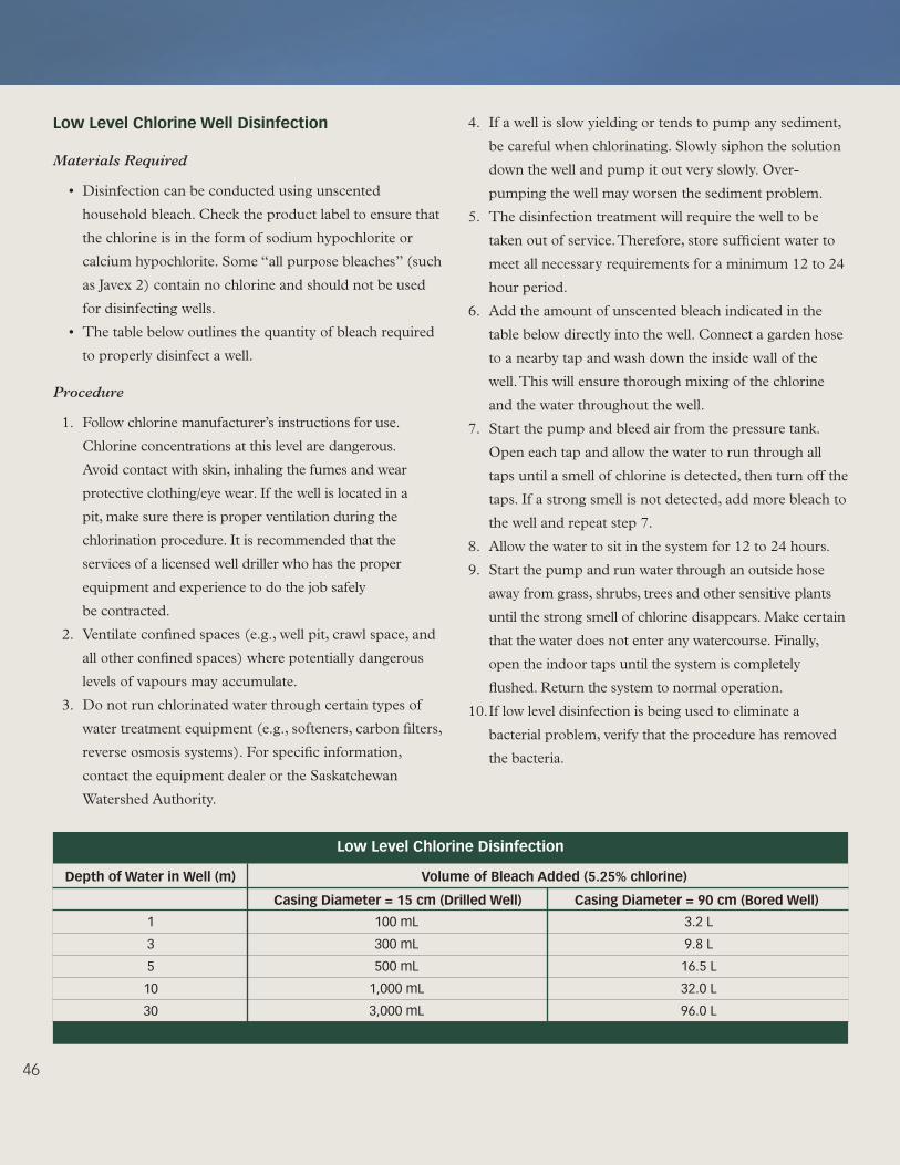
46
low level Chlorine Well Disinfection
Materials Required
•Disinfectioncanbeconductedusingunscented
household bleach. Check the product label to ensure that
the chlorine is in the form of sodium hypochlorite or
calcium hypochlorite. Some “all purpose bleaches” (such
as Javex 2) contain no chlorine and should not be used
for disinfecting wells.
•Thetablebelowoutlinesthequantityofbleachrequired
to properly disinfect a well.
Procedure
1. Follow chlorine manufacturer’s instructions for use.
Chlorine concentrations at this level are dangerous.
Avoid contact with skin, inhaling the fumes and wear
protective clothing/eye wear. If the well is located in a
pit, make sure there is proper ventilation during the
chlorination procedure. It is recommended that the
services of a licensed well driller who has the proper
equipment and experience to do the job safely
be contracted.
2. Ventilate confined spaces (e.g., well pit, crawl space, and
all other confined spaces) where potentially dangerous
levels of vapours may accumulate.
3. Do not run chlorinated water through certain types of
water treatment equipment (e.g., softeners, carbon filters,
reverse osmosis systems). For specific information,
contact the equipment dealer or the Saskatchewan
Watershed Authority.
4. If a well is slow yielding or tends to pump any sediment,
be careful when chlorinating. Slowly siphon the solution
down the well and pump it out very slowly. Over-
pumping the well may worsen the sediment problem.
5. The disinfection treatment will require the well to be
taken out of service. Therefore, store sufficient water to
meet all necessary requirements for a minimum 12 to 24
hour period.
6. Add the amount of unscented bleach indicated in the
table below directly into the well. Connect a garden hose
to a nearby tap and wash down the inside wall of the
well. This will ensure thorough mixing of the chlorine
and the water throughout the well.
7. Start the pump and bleed air from the pressure tank.
Open each tap and allow the water to run through all
taps until a smell of chlorine is detected, then turn off the
taps. If a strong smell is not detected, add more bleach to
the well and repeat step 7.
8. Allow the water to sit in the system for 12 to 24 hours.
9. Start the pump and run water through an outside hose
away from grass, shrubs, trees and other sensitive plants
until the strong smell of chlorine disappears. Make certain
that the water does not enter any watercourse. Finally,
open the indoor taps until the system is completely
flushed. Return the system to normal operation.
10. If low level disinfection is being used to eliminate a
bacterial problem, verify that the procedure has removed
the bacteria.
low level Chlorine Disinfection
1
3
5
10
30
Depth of Water in Well (m) Volume of bleach added (5.25% chlorine)
Casing Diameter = 15 cm (Drilled Well) Casing Diameter = 90 cm (bored Well)
100 mL
300 mL
500 mL
1,000 mL
3,000 mL
3.2 L
9.8 L
16.5 L
32.0 L
96.0 L

47
Disinfection Verification
• Untilwatertestingindicatesthatthewaterissafeto
use, find another source of water, or boil the water for
one minute, at a rolling boil, before consuming. This
precaution is particularly important for persons who are
immunocompromised and also if the water is being used
for infant feeding (preparing formula, etc.).
• Forprivate water supplies, it is recommended that a
sample be taken five days after treatment and another at
least one week after constant use. Two consecutive ‘safe’
test results are required to ensure that the treatment was
effective.
• ForHealth regulated public water supplies:- wells not receiving continuous treatment require a sample
taken five days after treatment and another at least one week after constant use,
- wells receiving continuous disinfection treatment require at least two consecutive sets of samples. The samples should be taken at least one day after the treatment and one day apart. Health Region officials will be advising the owner/operator of the supply on number of samples, sampling locations and when the water supply can be used again for human consumption.
• Ingeneral,allprivatesystemsshouldbeanalysedat
least once a year or whenever there is reason to believe
that the water supply may have become contaminated
(e.g. flooding).
• Healthregulatedpublicwatersuppliesmustsampleas
required by the Health Region.
Alternatives
Private Water Supply
If high level disinfection fails to correct the problem in a
private water supply, contact the local offices of Agriculture
and Agri-Food Canada – Agri-Environment Services
Branch, the Saskatchewan Watershed Authority, the
Saskatchewan Ground Water Association, or a Professional
Engineer or Geoscientist for further assistance.
Health Regulated Public Water Supply
If high level disinfection fails to correct the problem
in a Health regulated public water supply, contact
the local Health Region Public Health Inspector for
further assistance.
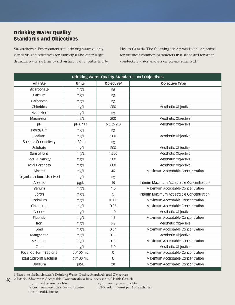
48
Drinking Water Quality standards and objectives
Bicarbonate
Calcium
Carbonate
Chlorides
Hydroxide
Magnesium
pH
Potassium
Sodium
SpecificConductivity
Sulphate
SumofIons
Total Alkalinity
Total Hardness
Nitrate
OrganicCarbon,Dissolved
Arsenic
Barium
Boron
Cadmium
Chromium
Copper
Fluoride
Iron
Lead
Manganese
Selenium
Zinc
Fecal Coliform Bacteria
Total Coliform Bacteria
Uranium
analyte
mg/L
mg/L
mg/L
mg/L
mg/L
mg/L
pH units
mg/L
mg/L
μS/cm
mg/L
mg/L
mg/L
mg/L
mg/L
mg/L
μg/L
mg/L
mg/L
mg/L
mg/L
mg/L
mg/L
mg/L
mg/L
mg/L
mg/L
mg/L
ct/100 mL
ct/100 mL
μg/L
Units
ng
ng
ng
250
ng
200
6.5 to 9.0
ng
200
ng
500
1,500
500
800
45
ng
10
1.0
5
0.005
0.05
1.0
1.5
0.3
0.01
0.05
0.01
5.0
0
0
20
objective¹
AestheticObjective
AestheticObjective
AestheticObjective
AestheticObjective
AestheticObjective
AestheticObjective
AestheticObjective
AestheticObjective
Maximum Acceptable Concentration
Interim Maximum Acceptable Concentration²
Maximum Acceptable Concentration
Interim Maximum Acceptable Concentration²
Maximum Acceptable Concentration
Maximum Acceptable Concentration
AestheticObjective
Maximum Acceptable Concentration
AestheticObjective
Maximum Acceptable Concentration
AestheticObjective
Maximum Acceptable Concentration
AestheticObjective
Maximum Acceptable Concentration
Maximum Acceptable Concentration
Maximum Acceptable Concentration
objective Type
1BasedonSaskatchewan’sDrinkingWaterQualityStandardsandObjectives2 Interim Maximum Acceptable Concentrations have been set by Health Canada mg/L = milligrams per litre μg/L = micrograms per litre μS/cm = microsiemens per centimetre ct/100 mL = count per 100 milliliters ng = no guideline set
Drinking Water Quality Standards and Objectives
Saskatchewan Environment sets drinking water quality
standards and objectives for municipal and other large
drinking water systems based on limit values published by
Health Canada. The following table provides the objectives
for the most common parameters that are tested for when
conducting water analysis on private rural wells.

49
There are three objective types used when referencing
drinking water quality guidelines and objectives:
1. Maximum Acceptable Concentration (MAC)
Maximum acceptable concentrations have been
established for substances that are known or suspected
to cause adverse effects on health. Objectives are set at
levels that will not cause hazardous health effects when
consumed at that concentration over a lifetime.
2. Interim Maximum Acceptable
Concentration (IMAC)
In some cases, there is insufficient toxicological data
to establish MACs with reasonable certainty. For these
substances, interim values are recommended, taking into
account the available health-related data, while at the
same time employing a safety factor to compensate for
the uncertainties involved.
3. Aesthetic Objective (AO)
Aesthetic objectives apply to substances or
characteristics of drinking water that can affect its
acceptability to consumers or interfere with practices
for supplying good quality water. In some cases, both
AO and health-related guidelines (MACs or IMACs)
have been derived. Where only aesthetic objectives are
specified, these values are below those considered to
constitute a health hazard.
Questionsrelatingtohumanhealthshouldbedirectedto
the local Health Region. Please refer to page 54 for contact
information.

50
Groundwater Management and Legal Requirements
Inventory of Groundwater Resources
in saskatchewan
The Saskatchewan Watershed Authority maintains a
groundwater database that comprises an inventory of wells
and test holes throughout the province. This information
provides guidance to the public in determining the potential
water supply at a given site. The information for a given area
determines the base of groundwater exploration, well depth,
yield, and water chemistry. Information can also be obtained
on different exploration methods, well design considerations,
possible water treatment requirements, well maintenance and
groundwater protection practices.
All inquiries and requests for assistance regarding
groundwater availability should be directed to the
Saskatchewan Watershed Authority’s Head Office in Moose
Jaw or to the nearest Saskatchewan Watershed Authority
Regional Office.
allocation and licensing
The Saskatchewan Watershed Authority is responsible
for administrating the regulatory approval process for
construction and operation of wells and other groundwater
works. The Saskatchewan Watershed Authority Act, 2005 and
The Ground Water Regulations provide details for the
requirements and processes in obtaining an approval.
Approvals are required to ensure proposed projects are
sustainable and do not cause adverse impacts to the
environment or other users. An approval is required for all
groundwater use except for domestic purposes. Domestic
purposes include water used for watering of stock (non-
intensive) and non-commercial lawns and gardens, as well
as household and sanitary purposes. Examples of works
requiring approval include municipal, industrial (including
groundwater dewatering), intensive livestock operations,
and irrigation.
Development of a Groundwater Source
The Saskatchewan Watershed Authority’s regulatory approval
process for the development of a non-domestic groundwater
source project has two parts. The developer of a proposed
groundwater development is required to obtain:
1. a Ground Water Investigation Permit; and
2. an Approval to Construct and Operate Works and Water
Rights Licence to Use Ground Water.
Ground Water Investigation Permit
The purpose of a groundwater investigation is to ensure
that the groundwater source can sustain the proposed
development without any adverse impacts on the source, or
existing groundwater users.
Approval to Construct and Operate Works and Water
Rights Licence to Use Ground Water
If the groundwater investigation was successful, the project
developer is required to file an Approval to Construct and
Operate Works and Water Rights Licence to Use Ground
Water under The Saskatchewan Watershed Authority Act, 2005.
Groundwater Regulations and legislation
Water Resources Legislation
The Saskatchewan Watershed Authority Act, 2005
The Saskatchewan Watershed Authority was established to
manage, administer, develop, control, and protect the water,
watersheds, and related land resources of Saskatchewan.
Included in this mandate, the Saskatchewan Watershed
Authority has the responsibility for administering the
approval process for the construction and operation of water
wells and other groundwater works, and the right to use
groundwater.
The Irrigation Act, 1996
The Irrigation Act is an act that aims to promote, develop and
sustain irrigation in Saskatchewan.

51
Water Quality Legislation
The Environmental Management and Protection Act, 2002
The Act gives the Minister of the Environment powers to
issue orders to investigate any activities that may pollute the
environment, to monitor for effects, to halt such activities,
and to restore the affected environment.
The Environmental Assessment Act
The Environmental Assessment Act authorizes the
Saskatchewan Ministry of Environment to review the
potential environmental effects of a proposed development.
Any project defined as a “development” must be approved by
the Minister of Environment before it is allowed to proceed.
The Public Health Act, 1994
The Public Health Act, 1994 gives authority to the Local
Authorities (i.e. Health Regions) for the administration and
enforcement of the Act. The Act also provides responsibilities
to municipalities to ensure that sewer systems and supply of
potable water systems are available to inhabitants of cities,
towns, villages and hamlets. The Local Authority can order
the abatement of any condition that is or may become a
health hazard.
The Pest Control Products (Saskatchewan) Act
The Pest Control Products (Saskatchewan) Act puts forth rules
for the handling, storage and use of pesticides.
The Boiler and Pressure Vessel Act, 1999
The Boiler and Pressure Vessel Act, 1999 is an act respecting
boilers and pressure vessels, as well as steam, refrigeration
and compressed gas plants.
The Agricultural Operations Act
The Agricultural Operations Act is an act respecting agricultural
operations, including intensive livestock operations.
Regulations
The Ground Water Regulations
The Ground Water Regulations put forth rules for the registration
of drilling machines, drilling and evaluation, the abandonment of
test holes and wells, and the use of groundwater.
The Water Regulations, 2002
The Water Regulations, 2002 set forth permit requirements
for municipal sewage works, certain pipeline systems, and
privately-owned water systems and that have a design flow
of effluent that is greater than 18 cubic metres per 24-hour
period. The regulations outline the requirements for the
construction and operation of these systems, and also state
the provincial drinking water quality standards.
The Hazardous Substances and Waste Dangerous
Goods Regulations
The Hazardous Substances and Waste Dangerous Goods
Regulations discuss the requirements to store or transfer
hazardous substances.
The Environmental Spill Control Regulations
The Environmental Spill Control Regulations discuss the
content and the method for submitting a spill report, as well
as regulations concerning the disposal of the spilled pollutant.
The Health Hazard Regulations
The Health Hazard Regulations require specific actions to be
taken by owners and operators of regulated water systems. In
addition, the regulations include requirements for bulk water
haulers, sanitary facilities at public places and the disposal of
dead animals.
The Plumbing and Drainage Regulations
The Plumbing and Drainage Regulations adopt with
amendments the Canadian Plumbing Code and require
plumbing permits to be applied for. It is also this regulation
that requires a permit for a private sewage works to be
applied for and lays out requirements for water and sewer
services within Mobile Home Parks.
The Shoreland Pollution Regulations
The Shoreland Pollution Control Regulations restrict
land uses within a shoreland development area (eg. within
1,500 ft of a water body). Included in these regulations are
restrictions on solid waste and sewage disposal works.

52
Contacts and Other Sources of Information
agriculture and agri-food Canada –
agri-environment services branch
North Saskatchewan
North Battleford District Office
Room 121 – 9800 Territorial Place
North Battleford, SK S9A 3N6
Ph: (306) 446-4050
Fax: (306) 446-4060
Website: www.agr.gc.ca
Melfort District Office
Box 1748
Bay 3 – 102 McKendry Avenue West
Melfort, SK S0E 1A0
Ph: (306) 752-4442
Fax: (306) 752-1991
Website: www.agr.gc.ca
Watrous District Office
Box 1150
107E 3rd Avenue East
Watrous, SK S0K 4T0
Ph: (306) 946-8720
Fax: (306) 946-3318
Website: www.agr.gc.ca
Rosetown District Office
Box 1420
219 Main Street
Rosetown, SK S0L 2V0
Ph: (306) 882-4272
Fax: (306) 882-4055
Website: www.agr.gc.ca
South Saskatchewan
Weyburn District Office
#21 110 Souris Avenue
Weyburn, SK S4H 2Z8
Ph: (306) 848-4488
Fax: (306) 848-4499
Website: www.agr.gc.ca
Gravelbourg District Office
Box 155
314 Main Street
Gravelbourg, SK S0H 1X0
Ph: (306) 648-2214
Fax: (306) 648-3402
Website: www.agr.gc.ca
Swift Current District Office
Box 1088
L.B. Thomson Place
Gate #2, SPARC, Airport Road
Swift Current, SK S9H 3X3
Ph: (306) 778-5000
Fax: (306) 778-5020
Website: www.agr.gc.ca
Maple Creek District Office
Box 430
Highway 21 and 2nd Avenue
Maple Creek, SK S0N 1N0
Ph: (306) 662-5520
Fax: (306) 662-3166
Website: www.agr.gc.ca
Moose Jaw District Office
1410A Caribou Street West
Moose Jaw, SK S6H 7S9
Ph: (306) 691-3370
Fax: (306) 693-3103
Website: www.agr.gc.ca
Melville District Office
Box 130
109 – 290 Prince William Drive
Melville, SK S0A 2P0
Ph: (306) 728-5790
Fax: (306) 728-6558
Website: www.agr.gc.ca

53
Canadian Ground Water association
Main Office
1600 Bedford Highway
Suite 100 – 409
Bedford, NS B4A 1E8
Ph: (902) 845-1885
Fax: (902) 845-1886
E-mail: [email protected]
Website: www.cgwa.org
Saskatchewan Ground Water Association
P.O. Box 9434
Saskatoon, SK S7K 7E9
Ph: (306) 244-7551
Fax: (306) 343-0002
saskH2o
Toll Free: 1-866 SASK H2O (727-5420)
Website: www.saskh2o.ca
saskatchewan Ministry of agriculture
Agriculture Knowledge Centre
Ph: 1-866-45-SAFRR (1-866-457-2377)
Email: [email protected]
Website: www.agriculture.gov.sk.ca
Regional Offices
Kindersley Regional Office
409 Main Street
Kindersley, SK S0L 1S0
Phone: (306) 463-5513
North Battleford Regional Office
1192-102nd Street
North Battleford, SK S9A 1E9
Ph: (306) 446-7964
Outlook Regional Office
Box 9
420 Saskatchewan Avenue West
Outlook, SK S0L 2N0
Phone: (306) 867-5575
Prince Albert Regional Office
Box 3003
800 Central Avenue
Prince Albert, SK S6G 6G1
Phone: (306) 953-2363
Swift Current Regional Office
Box 5000
350 Cheadle Street West
Swift Current, SK S9H 4G3
Phone: (306) 778-8218
Tisdale Regional Office
Box 1480
1105-99th Street
Tisdale, SK S0E 1T0
Phone: (306) 878-8842
Watrous Regional Office
Box 520
403 Main Street
Watrous, SK S0K 4T0
Phone: (306) 946-3220
Weyburn Regional Office
Box 2003
110 Souris Avenue
Weyburn, SK S4H 2Z9
Phone: (306) 848-2857
Yorkton Regional Office
38-5th Avenue North
Yorkton, SK S3N 0Y8
Phone: (306) 786-1531
saskatchewan Ministry of environment
3211 Albert Street Regina, SK S4S 5W6
Ph: (306) 787-2314
Website: www.environment.gov.sk.ca/
Spill Control Centre
Ph: 1-800-667-7525

54
saskatchewan Health
Regional Health Authority Offices
Athabasca Health Authority
Box 124
Black Lake, SK S0J 0H0
Ph: (306) 439-2200
Website: www.athabascahealth.ca
Cypress Health Region
429 – 4th Avenue NE
Swift Current, SK S9H 2J9
Swift Current, SK
Ph: (306) 778-5100
Website: www.cypresshealth.ca
Five Hills Health Region
455 Fairford Street East
Moose Jaw, SK S6H 1H3
Ph: (306) 694-0296
Website: www.fhhr.ca
Heartland Health Region
Box 2110
110 Highway #4 South
Rosetown, SK S0L 2V0
Ph: (306) 882-4111
Website: www.hrha.sk.ca
Keewatin Yatthe Health Region
Box 40
Buffalo Narrows, SK S0M 0J0
Ph: (306) 235-2220
Website: www.kyrha.ca
Kelsey Trail Health Region
Box 1780
Tisdale, SK S0E 1T0
Ph: (306) 873-6600
Website: www.kelseytrailhealth.ca
Mamawetan Churchill River Health Region
Box 6000
La Ronge, SK S0J 1L0
Ph: (306) 425-2422
Website: www.mcrrha.sk.ca
Prairie North Health Region
1092 – 107th Street
North Battleford, SK S9A 1Z1
Ph: (306) 446-6606
Website: www.pnrha.ca
Prince Albert Parkland Health Region
2nd Floor
1521 - 6 Avenue West
Prince Albert, SK S6V 7V6
Ph: (306) 765-6400
Website: www.paphr.sk.ca
Regina Qu’Appelle Health Region
2180 – 23rd Avenue
Regina, SK S4S 0A5
Ph: (306) 766-7755
Website: www.rqhealth.ca
Saskatoon Health Region
3rd Floor, Saskatoon Square
410 - 22nd Street East
Saskatoon, SK S7K 5T6
Ph: (306) 655-4605
Website: www.saskatoonhealthregion.ca
Sun Country Health Region
Box 2003
Weyburn, SK S4H 2Z9
Ph: (306) 842-8618
Website: www.suncountry.sk.ca
Sunrise Health Region
270 Bradbrooke Drive
Yorkton, SK S3N 2K6
Ph: (306) 786-0600
Website: www.sunrisehealthregion.sk.ca

55
saskatchewan Watershed authority offices
Head Office
Victoria Place
111 Fairford Street East
Moose Jaw, SK S6H 7X9
Ph: (306) 694-3900
Fax: (306) 694-3465
E-mail: [email protected]
Website: www.swa.ca
Regional Offices
Southeast - Weyburn Regional Office
Box 2003
3rd Floor, City Centre Mall
110 Souris Avenue
Weyburn, SK S4H 2Z9
Ph: (306) 848-2345
Fax: (306) 848-2356
E-mail: [email protected]
Website: www.swa.ca
Southwest - Swift Current Regional Office
Box 5000
3rd Floor, E.I. Wood Building
350 Cheadle Street West
Swift Current, SK S9H 4G3
Ph: (306) 778-8257
Fax: (306) 778-8271
E-mail: [email protected]
Website: www.swa.ca
Northeast - Nipawin Regional Office
Box 2133
201 – 1st Avenue East
Nipawin, SK S0E 1E0
Ph: (306) 862-1750
Fax: (306) 862-1771
E-mail: [email protected]
Website: www.swa.ca
East Central - Yorkton Regional Office
2nd Floor, 120 Smith Street East
Yorkton, SK S3N 3V3
Ph: (306) 786-1490
Fax: (306) 786-1495
E-mail: [email protected]
Website: www.swa.ca
Northwest – North Battleford Regional Office
402 Royal Bank Tower
1101 – 101st Street
North Battleford, SK S9A 0Z5
Ph: (306) 446-7450
Fax: (306) 446-7461
E-mail: [email protected]
Website: www.swa.ca
Other Offices
Regina Office
Park Plaza
Suite 420 – 2365 Albert Street
Regina, SK S4P 4K1
Ph: (306) 787-0726
Fax: (306) 787-0780
E-mail: [email protected]
Website: www.swa.ca
Saskatoon Office
330 – 350 Third Avenue North
Saskatoon, SK S7K 2H6
Ph: (306) 933-7442
Fax: (306) 933-6820
E-mail: [email protected]
Website: www.swa.ca

56
saskWater
Head Office
111 Fairford Street East
Moose Jaw, SK S6H 7X9
Ph: (306) 694-3098
Toll Free: 1-888-230-1111
Fax: (306) 694-3207
Other Offices
Watrous Office
Box 310
403 Main Street
Watrous, SK S0K 4T0
Ph: (306) 946-3200
Fax: (306) 946-3533
Prince Albert Office
McIntosh Mall
800 Central Avenue
Prince Albert, SK S6V 6G1
Ph: (306) 953-2250
Fax: (306) 953-225
24 Hour Emergency Number
1-800-667-5799
Water Quality
Saskatchewan Watershed Authority
RuralWaterQualityOffice
Ph: 1-866-TEST-H20 (1-866-837-8420)
accredited Water analysis laboratories
in saskatchewan
BDS Laboratories
13Qu’AppelleStreet
Box 363
Qu’Appelle,SKS0G4A0
Ph: (306) 699-2679
Toll Free: 1-888-BDS-Labs (1-888-237-5227)
Fax: (306) 699-7190
Website: www.bdslabs.com
Buffalo Pound Water Treatment Plant
Box 1790
Regina, SK S4P 3C8
Ph: (306) 694-1377
Fax: (306) 694-6050
ALS Laboratory Group
124 Veterinary Road
Saskatoon, SK S7N 5E3
Ph: (306) 668-8370
Toll Free: 1-800-668-9878
Fax: (306) 668-8383
Saskatchewan Ministry of Health
Disease Control Laboratory
3211 Albert Street
Regina, SK S4S 5W6
Ph: (306) 787-3131
Toll Free: 1-866-450-0000
Fax: (306) 798-0046
Saskatchewan Research Council
SRC Analytical Laboratories
422 Downey Road
Saskatoon, SK S7N 4N1
Ph: (306) 933-6932
Toll Free: 1-800-240-8808
Fax: (306) 933-7922

57
References
The following is a list of useful publications related to groundwater.
Groundwater
APrimeronFreshWater–QuestionsandAnswers.2000.
Environment Canada.
Groundwater – Nature’s Hidden Treasure. 1999.
Environment Canada.
The Health of Our Water – Toward Sustainable Agriculture in Canada. 2000.
Agriculture and Agri-Food Canada.
Groundwater Protection
Canadian Code of Practice for Environmentally Sound Hog Production. 1996.
Canada Pork Council.
Canadian Fertilizer Industry Storage and Handling Guidelines. 2001.
Canadian Fertilizer Institute.
Clean Water – Life Depends on It! 1992.
Environment Canada.
Developing a Manure and Dead Animal Management Plan. 2000.
Saskatchewan Agriculture and Food.
Environmental Review Guidelines for Intensive Livestock Operations. 2002.
Saskatchewan Agriculture and Food.
Establishing and Managing Livestock Operations. 2005.
Saskatchewan Agriculture and Food.
Guide for Land Disposal of Sewage. 1999.
Saskatchewan Environment.
Guide to Crop Protection. 2006.
Saskatchewan Agriculture and Food.
Holding Pond Site Selection and Design. 1999.
Saskatchewan Agriculture and Food.
Managing Manure as a Fertilizer. 2006.
Saskatchewan Agriculture and Food.
Manure Handling from Barn to Storage for Cattle.
Canada Plan Service Leaflet.

58
Manure Handling from Barn to Storage for Poultry.
Canada Plan Service Leaflet.
National Farm Building Code of Canada. 1995.
National Research Council of Canada.
Pesticide Safety Handbook. 1995.
Saskatchewan Agriculture and Food.
Protecting Your Ground Water. 2006.
Saskatchewan Watershed Authority.
Silage Storage Techniques.
Saskatchewan Agriculture and Food.
The Saskatchewan Onsite Wastewater Disposal Guide. 2007.
Saskatchewan Health.
Groundwater Quality
GuidelinesforDrinkingWaterQuality.
Health Canada.
Groundwater Use
Ground Water Approval Process. 2006.
Saskatchewan Watershed Authority.
Domestic Water Use. 2006.
Saskatchewan Watershed Authority.
Water Quality Testing
RuralWaterQualityCollectionandTesting.2006.
Saskatchewan Watershed Authority.
Water Treatment
Shock Chlorination for Ground Water Wells. 2006.
Saskatchewan Watershed Authority.
Well abandonment
Abandonment – Test Holes and Wells. 2006.
Saskatchewan Watershed Authority.