finalizer - mike baasto prevent electrical shock or fire hazard, do no expose the finalizer to rain...
TRANSCRIPT

FinalizerSTUDIO MASTERING PROCESSOR
USER’S MANUAL


3
TABLE OF CONTENTS
WELCOME FRONT PANELREAR PANELSIGNAL FLOWFINALIZER SETUPRECALLSTORE MAIN PAGESTOOLSWIZARDCOMPAREUTILITYRESET PAGETECHNICAL REFERENCETROUBLESHOOTINGMIDI IMPLEMENTATION CHARTSELF-TEST PROGRAMGLOSSARYAPPENDIX
About this Manual
Keys, LED’s and other functions explained
Recalling a Preset, Factory/User Presets, Memory Card
Store a New Preset, The Letterbox
Input, EQ, Inserts, Normalizer, Expander, Compressor, Limiter, Output, Crossover Freq.
Phase Meter, Calibration Tone, Flow, Peak-Hold Meter, Digital I/O
Reset Page, User Data Page
Maybe you will find help here
Tutorial
5689
101213142832333436373839404142

4
PRECAUTIONS
WARNING - THIS APPARATUS MUST BE EARTH-ED
Use only a three wire grounding type line cord,like the one supplied with the Finalizer.
Be advised that different operating voltages require the use of adifferent type line cord and attachment plug. In doubt contact your TC distributor.
Check the voltage in your area and use the correct type.
See table below:
CAUTION - Do not open the Finalizer.
Risk of electric shock inside. There are no user-serviceableparts inside. Refer servicing to qualified service personnel only.
Mount the Finalizer with a little space above and below in awell ventilated rack. Don't block the top or bottom.
To prevent electrical shock or fire hazard, do no expose theFinalizer to rain or moisture.
Do not rely solely on the front screws when mounted in touringrack. Support the back of the Finalizer as well.
Please report any shipment damage or equipment malfunctionsto your dealer, TC distributor or the TC head office inDenmark.
Voltage Line plug according to standard
110-125V UL817 and CSA C 22.2 no. 42
220-230V CEE 7 page VII, SR section 107-2-D1/IEC 83 page C4
240V BS 1363 of 1984. Specification for 13A. fused plugs and switched and un-switched socket outlets

5
WELCOMECongratulations on the purchase of your new Finalizer.We hope that you will have as much pleasure using itas we had making it.
The general control is accomplished by moving the cursor usingthe PARAMETER keys.Jumping between bands using the BAND keys.Changing block by using the BLOCK keys.Change page using the MENU keys and decrease/increase valuesby turning the ADJUST wheel.
The rest is simple. You select the area that you wish to control bypressing the function keys on the front of the Finalizer; i.e., ifyou want to recall, you press the RECALL key.
About this ManualMany people in the music business have an aversion to readingmanuals. We understand that. So, if you feel like starting withoutreading the whole manual, simply Plug & Play. You can alwaysuse the manual for checking out areas that you have questionsabout, or if you want to dig deeper into the unit, refer to theTable of Contents for further information. On the other hand, you might want to know a little more aboutthe Finalizer before you start pressing keys. The manual will takeyou step by step through all of the Finalizer’s functions. If youwant to read about a specific function, please refer to the Table ofContents.

6
FRONT PANEL
Input PPM GainReductionMeters
LimitLED’s
ExpanderActiveIndicators
INDICATORS
OverloadLights up if internal overloadoccurs.
Sample Rate Indicator48000 Hz44100 Hz32000 Hz
MIDI InMIDI receive indicator.
CardIndicates presence of a validmemory card.
WorkingIndicates that some calcula-tion is going on.
EditedPreset has been edited.
PC Card slotPresets may be copiedto/from a standard memorycard.
Electronic power switch»Easy touch«Keep pressed for more than1 second to turn device off.
Output PPMHigh resolution meters
SoftClip LEDIndicates that output is clipped

7
FUNCTIONS SECTION
Main PageThis button gives youaccess to edit the entiresignal flow, from input tooutput.
ToolsThis key gives you accessto a lot of useful tools foroptimizing your material.
WizardThe Wizard will do some ofthe hard work for you.
UtilityMIDI, Security, Memorymanagement and muchmore is located here.
PROGRAM SECTION
RecallRecall presets.
StoreStore and name presets.
CompareCompare the sound youhave right now with eithera leveled bypass or theoriginal preset.
BypassBypass the signal pro-cessing.
CONTROL SECTION
OKConfirm operationsand switch individual blocks on/off.
HelpGet help on selected display func-tion
Block < >Select which block to edit on themain page.
Menu up/downVertically oriented menu selector.
Parameter < >Moves horizontally for selection ofparameter to be modified.
Band < >Select between the three bands onthe com/lim/exp pages.On the EQ page, it selects which of the sixbands/level are displayed and ready for modi-fication.
Adjust wheelSets parameter values andpreset numbers.
8
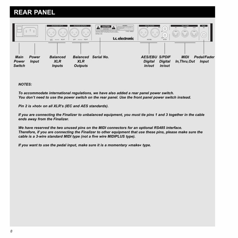
REAR PANEL
MainPowerSwitch
BalancedXLR
Inputs
BalancedXLR
Outputs
Serial No. AES/EBUDigitalin/out
S/PDIFDigitalin/out
MIDIIn,Thru,Out
Pedal/FaderInput
NOTES:
To accommodate international regulations, we have also added a rear panel power switch.You don’t need to use the power switch on the rear panel. Use the front panel power switch instead.
Pin 2 is »hot« on all XLR’s (IEC and AES standards).
If you are connecting the Finalizer to unbalanced equipment, you must tie pins 1 and 3 together in the cableends away from the Finalizer.
We have reserved the two unused pins on the MIDI connectors for an optional RS485 interface.Therefore, if you are connecting the Finalizer to other equipment that use these pins, please make sure thecable is a 3-wire standard MIDI type (not a five wire MIDIPLUS type).
If you want to use the pedal input, make sure it is a momentary »make« type.
PowerInput

9
SIGNAL FLOW
Notes regarding the signal flow:
The AES/EBU and the S/PDIF inputs are connected internally. Therefore, do not connect cables to bothAES/EBU and S/PDIF inputs at the same time.
As you can see from the block diagram, signals are present on all outputs, all of the time. To make thedithering circuit work appropriately, you must tell the system whether your main output is analog or digital(the I/O menu).

10
FINALIZER SETUP
Finalizer Setup The Finalizer is carefully designed to optimize the overall level and enhance the energy in your mix. The use of the three band compressor, limiter and expander makes the dynamics section of the Finalizer very flexible, whilemaintaining the fidelity of the original material. The dynamics section, in a combination with a normalizer and a five bandequalizer, gives you a very powerful tool, to finish the last details of your mix.
Because the Finalizer can be used in different applications, we propose a couple of different setups.

11
Setup with an analog mixing console and a digitalrecording device.
1. Connect the analog output of your mixer to the analog input ofthe Finalizer.
2. Connect the digital output of the Finalizer to yourdigital recording device.
3. Connect the analog output of the Finalizer to yourmonitor system.
Example 1
Example 2
Example 3
Setup with a digital mixing console and a digitalrecording device
1. Connect the digital output of your mixer to the digital input ofthe Finalizer.
2. Connect the digital output of the Finalizer to yourdigital recording device.
3. Connect the analog output of the Finalizer toyour monitor system.
Mastering from DAT to DAT
1. Connect the digital output of DAT #1 to the digital inputof the Finalizer.
2. Connect the digital output of the Finalizer to the digitalinput of DAT #2.

12
Preset banks
FactoryPresets
Your ownPresets
The Finalizer contains two different preset banks.
The RAM bank can hold up to 128 presets.
The RAM preset bank is located after the ROM bank. Thismeans that you scroll through the ROM presets to enter the RAMbank.
For fast RAM/ROM access use the BLOCK keysto switch between the two banks.
Note: When previewing in the RAM bank you will not see theempty RAM space.
Factory/User Presets
RECALL
Select which blocks will be loadedfrom new preset.
Preset name
Preset number
ROM bank RAM bank
RecallWhen you wish to recall a preset, simply use the ADJUST wheelto scroll through the presets and press OK to recall.The OK key will be blinking while you are previewing, indicat-ing that the shown preset is not recalled yet.
It is also possible to recall separate sections of a pre-set. Select the desired section, using the PARAMETERkeys, and press OK.
The Recall DisplayIn the Recall display, you will see an information section at thebottom of the screen. In this section you are able to see whichblocks are turned on in the current preset, and also a small EQpreview with a miniature icon of the EQ setting.
In the upper right corner, you see an indication of which bankyou are previewing.
Short info about preset
128 RAMPRESETS
ROMPRESETS

13
STORE
Store a New RAM Preset- Press the STORE button- Select a location for your new preset [dial between preset 1 to 128]- Move the cursor to the new name line and dial in the new preset name [find letter with ADJUST and confirm with OK ]- Move the cursor to DONE and press OK to finalize store operation.
Store with the same name:If you want to store the preset with the existing name, simply select the RAM location to store it in by using the ADJUST wheel and pressOK (the OK key will be blinking while you search for a suitable RAM space). The Finalizer will now tell you “STORED” in a pop-up win-dow and return to the main page.
Store location
The LetterboxWhen you want to change the name of the preset to store, pressthe MENU down key. You are now able to write a new nameusing the letterbox. Simply dial the ADJUST wheel and press OKto select new letters.Select CAP, by pressing OK, to change case.When you have changed the name, select DONE in the Letterboxand press OK to Store.
You can use the PARAMETER keys to move thecursor.
Delete a PresetWhen you want to delete a preset, simply select Delete using theBLOCK keys, select the preset to be deleted, and press OK.
New preset name
Letterbox
Cursor arrows
CAPS LOCKIndicator
Place cursor here and press OKto finalize store operation
Using a Memory Card:When you wish to use a memory card, simply insert the card inthe Finalizer. The Finalizer will now autodetect your card and theStore and Recall facilities will be attached to the memory card.The Finalizer will now use the memory card as a normal RAMbank. When you remove your memory card, the Finalizer willswitch back to the internal RAM.
If the format of the memory card is not correct, the Finalizer willdetect this immediately.
Card typesType 1 PC Cards with minimum 64 KBytes of SRAM.

14
MAIN PAGE Input
Set input levels Selectinput
Sample Rate:44.1kHz, 48kHzor from Digital Input
LowCut Filter
Select between con/proanalog input levels.
Select the IN section on the Main page by pressing theBLOCK keys.
These global level controls should be set to optimize the perfor-mance of the 20 bit A to D converter in the Finalizer.
Basic operationPress the PARAMETER keys to move the cursor, and turn theADJUST wheel to change values.
Left & RightThe input bars can be operated individually or in common.Highlight both bars for common operation by pressing thePARAMETER keys. The range of the input bars depends on theinput type (Analog/Digital) and the input level(Professional/Consumer).
Note: The input bars are always common when digital input isselected.
Ranges
Analog InputsConsumer (-10 dBu): -16 dB to +10 dBProfessional (+6 dBu): -6 dB to +16 dB
Digital Inputs -16 dB to +6 dB
Sample Rate (Srate): Select master clock44.1 kHz/48 kHz/DI
When Digital Input is selected, the external clock frequency willbe displayed by the three LEDs on the left hand side of the dis-play. If the Finalizer can not lock, none of the LEDs will be lit.
Note: When changing the input to digital, the sample rate para-meter is automatically set to DI.
LowCutThe lowcut filter is global, and is used to filter out any sub-bassfrequency or DC contents in the current signal.

15
MAIN PAGE EQ
Effects blocks
Black box indicates selected blockEQ on/off
Parameter
Band Output Level bar
Selected band
Frequency Gain Bandwidth/Slope
EQSelect EQ by pressing the BLOCK keys.
Basic operationPress PARAMETER keys to select frequency/gain/bandwidth/slope. Turn ADJUST wheel to change values. Press BAND keys to jump between the five bands.
EQ RangesFrequency Gain Bandwidth/Slope
Low Shelve 19.95 Hz to 5.01 kHz +/- 12 dB 3, 6, 9, 12 dB/OctBell-shaped filter 1 19.95 Hz to 20 kHz +/- 12 dB 0.1 Oct to 4.0 OctBell-shaped filter 2 19.95 Hz to 20 kHz +/- 12 dB 0.1 Oct to 4.0 OctBell-shaped filter 3 19.95 Hz to 20 kHz +/- 12 dB 0.1 Oct to 4.0 OctHigh Shelve 501.2 Hz to 20 kHz +/- 12 dB 3, 6, 9, 12 dB/OctOutput Gain - +/- 12 dB -
EQ BypassPress the blue BLOCK on/off key to bypass the EQ section.
Reset all filters by pressing both page keys simultaneously.

16
MAIN PAGE Inserts
Insert type selectorSelect between:- None- Digital Radiance- Stereo Adjust- De-essing
Insert selected
This parameter deter-mines the drive of the
Radiance Generator.
If your material is asymmetric(percussion/speech etc.) thisparameter will change thesound.
Move cursor up to increase the stereo width.Move cursor down to make the signal more mono.Center position is normal.
Move the cursor right/left to adjust center (balance)
STEREO ADJUST
DIGITAL RADIANCE GENERATOR
THRESHOLDRATIO
ATTACKRELEASE
FREQUENCY sets the cutoff freq.of the de-esser.
CURVE sets the frequency char-acteristics of the dynamic damp-ing filter.
DE-ESSER

17
MAIN PAGE Inserts
InsertsSelect Insert by pressing the BLOCK keys
The Finalizer has various insert possibilities. Choose betweenDRG, Stereo Adjust or De-essing by pressing the MENUup/down keys.
Note: You can use only one insert function at a time.
Basic operation- Use MENU keys to select insert effect.- Press the PARAMETER keys to select parameter. - Turn the ADJUST wheel to change values.
Stereo Adjust With Stereo Adjust, you can change the stereo information of thesignal. Turn the MS parameter clockwise to increase stereo widthand counter clockwise to make the signal more mono-like.
You can change the left/right balance with the LR parameter.
De-esserThis algorithm removes unwanted »esses« from vocal materialby dynamically reducing the level of high frequencies.
ThresholdUse the ADJUST wheel to change the threshold of the de-esser.AttackUse the ADJUST wheel to change the attack time of the de-esser.ReleaseUse the ADJUST wheel to change the release time of the de-esser.Ratio Use this parameter to adjust the damping ratio of the de-esser.Frequency The frequency sets the cut-off frequency of the de-esser.CurveWith the curve parameter, you select whether the de-esser shouldwork with a bell-shaped or shelving filter.
Digital Radiance GeneratorThe DRG (Digital Radiance Generator) adds second harmonicdistortion to the signal. This kind of distortion is very analog-like, and will add a certain warmth to your material.
DriveThe DRG drive is adjustable from 0 to 10.CurveIf your material is asymmetric (percussion/speech, etc.), theplus/minus parameter will change the sound of the DRG.

18

19
MAIN PAGE Normalizer
Effects blocks
Black box indicates selected block
No. of consecutivesamples clipped.
Normalizing gain Clipping method
NormalizerOptimizing the level of your material starts in the Normalizer. Here you have a graphical presentation of the incoming signal, shown as 1 second pictures. By increasing the gain, you decrease the headroom, shown as two dotted lines.You should set the gain such that the signal peaks are just hitting the dotted headroom lines.
The Normalizer is capable of gaining +18 dB.
The Clipper The Normalizer has a build-in limiter, which can be either soft or hard. When the Normalizer limiter is active, it is indicated on theNormalizer LIM LED above the Input Meters.
The Clip Counter indicates the maximum number of consecutive samples clipped within the last second.
If the clips only occur occasionally, and only few samples are clipped per test interval, you do not necessarily have to reduce the gain of theNormalizer.

MAIN PAGE Expander
Y-axis is outputlevel.
USER PAGE
EXPERT PAGE
Arrow direction indicateswhether the parameter valuehas been increased ordecreased since last recall.
PAGES- User page- Expert page- Cross-over frequency page
X-axis is inputlevel.
Expanderthreshold
low/mid/high
Attack timelow/mid/high
Releasetime
low/mid/high
Side chain / delayThis parameter inserts the indicated delay inthe main signal path.The side chain will therefore be able to lookahead on the input signal, enabling it torespond faster to sudden signal changes.
This parameter is common for expander/com-pressor/limiter.
Ratiolow/mid/high Use band select cursors to access
individual bands.
CROSS-OVER FREQUENCY PAGE
20

21
ExpanderSelect EXP by pressing the BLOCK keys
Basic Operation- Press the PARAMETER keys to select parameter. - Turn the ADJUST wheel to change values. - Press the BAND keys to select between the three bands.- Press the MENU keys to select User/Xpert/Xover.
User MenuThresholdUse the ADJUST wheel to change the thresholds of the threebands.Ratio Use these parameters to adjust the ratios of the three expanderbands.Expander MonitorThe Expander Monitor gives you a graphical picture of the ratioand threshold settings.
Expert MenuPress MENU keys to enter expert mode (XPRT)
AttackUse the ADJUST wheel to change the attack time of the threebands.ReleaseUse the ADJUST wheel to change the release time of the threebands.Side Chain / DelayThis parameter adjusts the “look-ahead” delay. This means thatyour audio signal is delayed, i.e., 10 ms. By slightly delaying the audio signal, you give the processor achance to look ahead at the present signal, and will thereforereact more accurately than a standardcompressor/limiter/expander.The actual look-ahead delay time is scaled with the attack timeindividually on all three bands.
Note: This delay time parameter is common for the compressor,limiter and expander.
Cross-over MenuPress MENU keys to enter the cross-over frequencypage (Xovr)
L-Xovr/H-XovrWith the L-Xovr and H-Xovr you set the cross-over points of thethree bands in the dynamics section.
Note: The cross-over points are common for the compressor, lim-iter and expander.
The Edit GuideThe symbol in the lower left corner of the display is an editguide. This indicator will help you get back to parameter valuesof the latest recalled preset.
Arrow direction indicates whether the parameter valuehas been increased or decreased since last recall.
Example:If you have been working on various parameters within a presetand would like to get the original ratios back without changingthe attack/release times, simply select the ratio parameters oneby one and follow the edit guide.
Expander BypassPress the blue BLOCK on/off key to bypass the expander section.

22
MAIN PAGE Compressor
USER PAGE
EXPERT PAGE
Page select:1. User page2. Expert page 3. Cross-over page
Thresholdlow/mid/high
Ratiolow/mid/high
Band levelslow/mid/high
Output level
AttackTimes
low/mid/high
ReleaseTimes
low/mid/high
CrestThis parameter determineswether the compressorshould react to peaks,RMS (average), or some-thing in between.
Side chain / Delay(same as under
expander)CROSS-OVER FREQUENCY PAGE
Arrow direction indicateswhether the parameter valuehas been increased ordecreased since last recall.

23
The CompressorSelect COM by pressing the BLOCK keys
Basic operation- Press the PARAMETER keys to select parameter. - Turn the ADJUST wheel to change values. - Press the BAND keys to select between the three bands.- Press the MENU keys to select User/Xpert/Xover.
About the CompressorThe compressor section of the Finalizer is divided into threebands. This means that you are able to compress thelow/mid/high frequencies separately.To optimize the output gain and energy in your material, theFinalizer uses auto-makeup gain, meaning that the three bandsare gained individually and automatically, depending on howhard the current band is compressed.
User MenuThresholdUse the ADJUST wheel to change the thresholds of the threebands.Ratio Use these parameters to adjust the ratios of the three compressorbands.Band LevelThe three band levels are used to adjust the spectral balance inthe compressor. You are able to change the level of the low, midand high bands individually, simply by selecting the current bandand turning the ADJUST wheel.Out LevelWith this parameter you can adjust the overall output of the com-pressor.
Expert MenuPress MENU keys to enter the expert page.
AttackUse the ADJUST wheel to change the attack time of the threebands.ReleaseUse the ADJUST wheel to change the release time of the threebands.
Side Chain / DelayThis parameter adjusts the look-ahead delay. This means thatyour audio signal is delayed, i.e., 10 ms. By slightly delaying the audio signal, you enable the processor tolook ahead at the present signal, and it will, therefore, react moreaccurately than a standard compressor/limiter/expander.
The actual look-ahead delay time is scaled automatically with theattack time, individually on all three bands.
Note: This delay time parameter is common for the compressor,limiter and expander.
CrestThis parameter determines whether the compressor should reactto peaks, RMS (average), or something in between. For exampleif the crest parameter is set at 6 dB, the compressor is reacting toRMS values and to peaks 6 dB higher than the current RMSvalue.
Cross-over MenuPress MENU keys to enter the cross-overfrequency page (Xovr)
L-Xovr/H-XovrWith the L-Xovr and H-Xovr you set the cross-over points of thethree bands in the dynamics section.
Note: The cross-over points are common for the compressor, lim-iter and expander.
Compressor BypassPress the blue BLOCK on/off key to bypass the com-pressor section.

24
MAIN PAGE Limiter
Expert mode on/off
Arrow direction indicateswhether the parameter value
has been increased ordecreased since last recall. Limiter
thresholdlow/mid/high
Bypass individuallimiter bands.
Clipping methodThe clip function smoothly killsany overshoot that might occurafter heavy compression or limit-ing. The higher the percentage,the softer the clip.
USER PAGE
EXPERT PAGE
CROSSOVER FREQUENCY PAGE
AttackTimes
low/mid/high
ReleaseTimes
low/mid/high
Digital ceilingThis parameterreduces the fullscale (0dB) signallevel on the output.
Side chain / Delay(same as under
compressor /expander)

25
The LimiterSelect LIM by pressing the BLOCK keys
Basic operation- Press the PARAMETER keys to select parameter. - Turn the ADJUST wheel to change values. - Press the BAND keys to select between the three bands.- Press the MENU keys to select User/Xpert/Xover.
User MenuThresholdUse the ADJUST wheel to change the thresholds of the threebands.On/OffUse these parameters to enable/disable the three limiter bands.ClipThe clip function smoothly kills any overshoot that might occurafter heavy compression or limiting. The higher the percentage,the softer the clip.
Expert MenuPress MENU keys to enter the expert page.
AttackUse the ADJUST wheel to change the attack time of the threebands.ReleaseUse the ADJUST wheel to change the release time of the threebands.Side Chain / DelayThis parameter adjusts the look-ahead delay. This means thatyour audio signal is delayed, i.e., 10 ms.
By slightly delaying the audio signal, you enable the processor tolook ahead at the present signal, and it will, therefore, react moreaccurately than a standard compressor/limiter/expander.
The actual look-ahead delay time is scaled automatically with theattack time, individually on all three bands.
Note: This delay time parameter is common for the compressor,limiter and expander.
Digital CeilingWith the digital ceiling you can adjust the digital maximum out-put, i.e., if you receive an overload indication on the device con-nected to the DI/out of the Finalizer, you are able to reduce theoutput level down by 0.01 dB increments.
Cross-over MenuPress MENU keys to enter the cross-over frequencypage (Xovr)
L-Xovr/H-XovrWith the L-Xovr and H-Xovr you set the cross-over points of thethree bands in the dynamics section.
Note: The cross-over points are common for the compressor, lim-iter and expander.
26
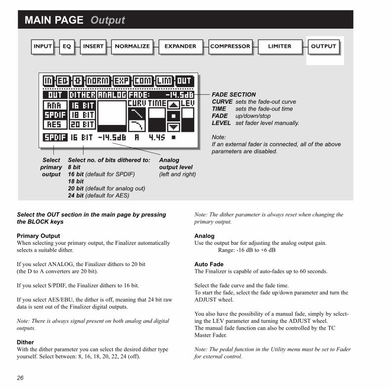
MAIN PAGE Output
Analogoutput level(left and right)
Selectprimaryoutput
Select no. of bits dithered to:8 bit16 bit (default for SPDIF)18 bit20 bit (default for analog out)24 bit (default for AES)
FADE SECTIONCURVE sets the fade-out curve TIME sets the fade-out timeFADE up/down/stopLEVEL set fader level manually.
Note:If an external fader is connected, all of the aboveparameters are disabled.
Select the OUT section in the main page by pressingthe BLOCK keys
Primary OutputWhen selecting your primary output, the Finalizer automaticallyselects a suitable dither.
If you select ANALOG, the Finalizer dithers to 20 bit(the D to A converters are 20 bit).
If you select S/PDIF, the Finalizer dithers to 16 bit.
If you select AES/EBU, the dither is off, meaning that 24 bit rawdata is sent out of the Finalizer digital outputs.
Note: There is always signal present on both analog and digitaloutputs.
DitherWith the dither parameter you can select the desired dither typeyourself. Select between: 8, 16, 18, 20, 22, 24 (off).
Note: The dither parameter is always reset when changing theprimary output.
AnalogUse the output bar for adjusting the analog output gain.
Range: -16 dB to +6 dB
Auto FadeThe Finalizer is capable of auto-fades up to 60 seconds.
Select the fade curve and the fade time.To start the fade, select the fade up/down parameter and turn theADJUST wheel.
You also have the possibility of a manual fade, simply by select-ing the LEV parameter and turning the ADJUST wheel.The manual fade function can also be controlled by the TCMaster Fader.
Note: The pedal function in the Utility menu must be set to Faderfor external control.

27

28
TOOLS Phase Meter (correlation)
Time/divisionCurve speed
TOOLS Calibration Tone
Phase MeterThe phase meter show you the phase relationshipbetween the two stereo channels.
Plus means that the two channels are in phase.Minus means that the two channels are in anti-phase.
Time/divisionSets the curve drawing speed.
Calibration toneIn the calibration display you have a 1000 Hz test-tone, which will be sent out on the Finalizers out-puts at the selected level.
Set the level by using the ADJUST wheel and pressOK to activate.

29
TOOLS Flow
Internal levels (ppm)
TOOLS Peak-Hold Meter
Numeric readout of peak values
FlowIn the Flow Meter, you have six small peak meters,representing the level in the different sections ofthe Finalizer.
This can be very helpful in a number of situations.I.e. you have an overload indication on the front,but you do not know in which section the overloadis located: now you simply press TOOLS and selectthe Flow meter, and you have instant view of alllevels and possible overloads in the Finalizer.
PeakThe Peak-Hold Meter is an output meter with infi-nite hold. It is possible to see the level of the maxi-mum peak in 0.10 dB precision.
Press OK to reset the meter.

30
TOOLS Digital I/O (DIO)
Pre-emphasis indicator: on/off
RECEIVED STATUS BITS
DIGITAL OUT STATUS BITS
CopyrightHere you can set the copyrights
on the outgoing digital audio.
Source device: DAT, CD, mixer etc.Numbers of audio bits received.Copyright: None, One copy only , Infinite copies
Status bits on digital output:AES/EBU: Professional usage of status bits.S/PDIF: Consumer usage of status bits.FROM INPUT: Status bits received on input arefed through to the digital output.

31
TOOLS Digital I/O (DIO)
INOn this display you have various indicators that tellyou what kind of digital signal you are receiving.
Pre-emphasisThis parameter tells whether the incoming signal is pre-empha-sized or not.Source device (Category code).The device status of the received signal is shown in this indicator.Audio dataThe number of received audio bits is indicated here.Copyright (Copy inhibit).
Status of the copybits.
OUTOn this display you set up how the Finalizer shouldsend out your material.
COPY ENABLESet the copyrights of your material:
- No copies- 1 copy only- Infinite number of copies.
Note: The copy protection is only valid with S/PDIF signals.
STATUS BITS OUT
AES/EBUWhen AES/EBU is selected the Finalizer will send out its ownprofessional set of status bits, meaning that any incoming ID willbe lost. However, in order to take full advantage of theFinalizer’s 24 bit resolution you should select AES/EBU to makesure that the receiving device after the Finalizer will accept all 24bits.S/PDIFWhen S/PDIF is selected, the Finalizer will send its own con-sumer status bits out, meaning that any incoming ID will be lost.The Finalizer’s S/PDIF output carries up to 20 bits. Only theS/PDIF signal contains copy protection information.From InputWhen this setting is selected the Finalizer will send the sameinformation out as it received. However, you still have the possi-bility to change the copy status.

32
WIZARD
Select source type: soft/medium/hard
Select degree of compression:soft/medium/hard
Optimize gainIf this option is selected the Finalizer will adjustthe Normalizer level.
Press OK to start procedure
EQThe Finalizer will adjust the Equalizer to the selectedspectral expression.
Wizard - Making the whole thing very simplePress the WIZARD key.
With the Wizard you set a couple of terms, and the Wizard will select the optimal settings for you: the Normalizer, Compressor, Limiter andEQ.
Select whether your source type is soft, medium or hard, using the ADJUST wheel.Select which kind of compression you like: Soft, medium or hard.
Do you want your material to be gain optimized? Yes or no.
Note: If you use auto-gain, the Wizard will be measuring until you stop it. This means that you can run all of your material through the Wizard to get the optimum level.
Select which EQ setting you would like: Flat (no EQ), Loudness, Bass-lift or Air.
Press the OK key to carry out the settings of the Wizard.
Press any key to stop the Autogain function.

33
COMPARE
CompareThe reason for adding this compare function is that it can be difficult to estimate what the EQ/dynamics is doing to the sound of your mate-rial. Because of the extra gain of the Normalizer and the compressor in-circuit and out-of-circuit comparisons are often difficult to makeusing the BYPASS key. That is why we made it possible to reduce the level of your processed setting when comparing it with the bypassed sound. You can evencompare with the last recalled preset.
Press the COMPARE key and use the ADJUST wheel to lower the level of your setting. Then use the PARAMETER keys to compare these different sounds: one, the original; two, your edited preset; or three, the bypassed sig-nal.
Listen to original presetIf you place cursor here, you will hear
the original preset.
Listen to your edited soundIf you place the cursor here, you will
hear the edited sound.
Use the ADJUST wheel to adjust thislevel for better comparison with the
bypassed signal.
Bypassed signalSame function as the BYPASS key.
34
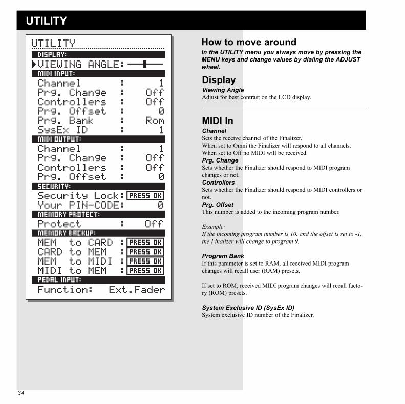
UTILITY
DisplayViewing AngleAdjust for best contrast on the LCD display.
MIDI In ChannelSets the receive channel of the Finalizer.When set to Omni the Finalizer will respond to all channels.When set to Off no MIDI will be received.Prg. ChangeSets whether the Finalizer should respond to MIDI programchanges or not.ControllersSets whether the Finalizer should respond to MIDI controllers ornot.Prg. OffsetThis number is added to the incoming program number.
Example:If the incoming program number is 10, and the offset is set to -1,the Finalizer will change to program 9.
Program BankIf this parameter is set to RAM, all received MIDI programchanges will recall user (RAM) presets.
If set to ROM, received MIDI program changes will recall facto-ry (ROM) presets.
System Exclusive ID (SysEx ID)System exclusive ID number of the Finalizer.
How to move aroundIn the UTILITY menu you always move by pressing theMENU keys and change values by dialing the ADJUSTwheel.

35
Memory Protect ProtectThis parameter sets the memory protection on or off. When pro-tect is on, the RAM presets between the high and low limits arewrite protected.
Memory BackupMem > CardInsert a PC Card in the card slot and press OK. All RAM presetsof the Finalizer will now be backed up to the memory card.Card > MemInsert the PC Card containing your presets and press OK. Allpresets will now be stored back into the Finalizer RAM.
Warning:This action will destroy all existing RAM presets of the Finalizer.
Mem > MIDIConnect your Finalizer’s MIDI output to another Finalizer, asequencer or any other MIDI recording device. Press OK and theFinalizer will perform a MIDI bulk dump of all RAM presets.MIDI > MemConnect the storing device to the Finalizer’s MIDI input andpress OK. The Finalizer is now ready to receive a MIDI bulkdump containing RAM presets.
Warning:This action will destroy all existing RAM presets of the Finalizer.
Pedal InputSelect between: External Fader/Fade up-down/Bypass.
MIDI OutChannelMIDI transmit channel.Prg. ChangeSets whether the Finalizer should transmit MIDI programchanges or not.ControllersSets whether the Finalizer should transmit MIDI control changesor not.OffsetThis number is added to the outgoing program number.
SecurityTo security-lock the Finalizer, press OK while this parameter isselected.
When locked, you will have to dial the PIN-code shown belowto access the Finalizer.
PIN-codeSets your PIN-code for the security lock by dialing the ADJUSTwheel (See page 36).
If you should forget your PIN-code, please enter the Reset page.This will release the Finalizer from the locked state.(You do not have to run any of the reset functions).

36
RESET PAGE
How to enter the Reset page:Hold the BYPASS key pressed while powering up.
Move the marker using the MENU keys and press OKto select reset type.
Load User DefaultThis will reset all system parameters back to a default setup madeby you (see Store User Def.). This reset will NOT delete the userpresets of the Finalizer.Store User Def.When you have a perfect setup of your Finalizer, you are able tostore this as your own default setup. This function is very useful,for example when you have finished a special production andwant to go back to normal. When you have the perfect setup ofyour Finalizer, simply select this parameter and press OK to storeyour default settings. The User Default includes all system parameters.
Set User NameThis function makes it possible to write your name and phonenumber into the Finalizer. Press OK to access the user data menu.Use the ADJUST wheel and the MENU keys to write your nameand phone number into the Finalizer. Press OK to accept. Yourname and phone number will be displayed during power-up.Reset System ParametersThis will reset all system parameters back to the factory default.This reset will NOT delete the user presets of the Finalizer.Reset all PresetsThis will clear all RAM presets.
Store and load your owndefault settings
Enter User data page
Reset system parameters
Clear all user presets
Test Programs
Type your name here
and your phone number
Place cursor hereand press OK tofinalize session.

37
TECHNICAL SPECIFICATIONSAnalog InputConnectors: XLR balanced (pin 2 hot)Impedance: 15 kOhmMax. Input Level: +22 dBuSensitivity: @ 12 dB headroom: -22 dBu to 10 dBuA to D Conversion: 20 bit (4 bit, 64 times oversampling)Dynamic Range: > 105 dBTHD: < 0.003% @ 1 kHz, +10 dBFrequency Response: 10 Hz - 20 kHz: +0/-0.2 dBCrosstalk: -60 dB max, 10 Hz to 20 kHz
Analog OutputConnectors: XLR balanced (pin 2 hot)Impedance: 100 Ohm (active transformer)Max Output Level: +22 dBuOutput Gain Range: 0 to -32 dBD to A Conversion: 20 bit (1 bit 128 times oversampling)Dynamic Range: > 96 dBTHD: < 0.008% @ 1 kHz, +10 dBFrequency Response: 10 Hz - 20 kHz: +0/-0.3 dBCrosstalk: -60 dB max, 10 Hz to 20 kHz
Digital Inputs and OutputsAES/EBU In/Out: XLRS/PDIF In/Out: Coaxial, RCA TypeFormats: EIAJ CP-340, IEC 958, S/PDIF (20 bit)
AES/EBU (24 bit)Sample Rates: 32 kHz, 44.1 kHz and 48 kHz
PC-CARD InterfaceConnector: Type 1 PC CardsStandards: PC-CARD 2.0, JEIDA 4.0Card Format: Supports up to 2 MB SRAM
Control InterfaceMIDI: In/Out/Thru: 5 Pin DINPedal: 1/4 inch phone jack
GeneralFinish: Black anodized aluminum face plate
Painted and plated steel chassisDimensions: 19” x 1.75” x 8.2” (485 x 45 x 195 mm)Weight: 5.2 lbs (2.35 kg)AC Power: 90 - 240 VAC without switch settings
3 Pin IEC power connectorBattery Life: >10 years
Radio Frequency Immunity/InterferenceRFI/ESD: Conforms to FCC Class B,
EN55103-1 (CE), EN55103-2 (CE)
EnvironmentOperating Temperature: 32OF to 122OF (0OC to 50OC)Storage Temperature: -22OF 167OF (-30OC to 70OC)Humidity: Max. 95% non-condensing
All specifications are subject to change without notice.

38
TROUBLESHOOTING
You press the POWER switch but there is no light.- The power switch on the rear panel is switched off.
The input PPM meters don’t peak out.- You are using analog inputs, but the input selector in the I/O menu is set to digital in.- The analog input level is set too low.
No sound through the Finalizer- You are using analog inputs, but the input selector in the I/O menu is set to digital in.
You cannot turn the power off.- Hold the power switch pressed for at least 3 seconds.

39
MIDI IMPLEMENTATION CHARTSTUDIO MASTERING PROCESSOR: Finalizer - JUNE 24, 1996 Version 1.0
Function Transmitted Recognized RemarksBasic Channel Default 1 1
Changed 1-16 1-16Mode Default
Messages X XAltered
Note Number X XTrue Voice X X
Velocity Note ON X XNote OFF X X
After Touch Key’s X XCh’s X X
Pitch Bend X XControl Change O O
Prog Change O OTrue# 0-127 0-127
System Exclusive O OCommon :Song Pos X X
:Song Sel X X:Tune X X
System real time :Clock O O:Commands X X
Aux Messages :Local ON/OFF X X:All Notes OFF X X:Active Sense X X:Reset X X
Notes
O:YES Mode1: OMNI ON, POLY Mode 2: OMNI ON, MONOX:NO Mode 3: OMNI OFF, POLY Mode 4: OMNI OFF, MONO

40
SELF TESTPRESS ONE OF THE 3 BYPASS KEYS, WHILE POWER-ING UP, TO ACCESS THE SELF-TEST AND SELECT»RUN TEST PROGRAM«
Turn the ADJUST Wheel to scroll through self tests
Key testSelect Key test by pressing OK.The keys must be pressed in the order they are requested by theFinalizer to pass the test.Press OK key again to exit test.
Adjust Wheel testSelect Adjust Wheel test by pressing OKTurn the Adjust Wheel to 30 and back to 0 to pass test.Press OK key again to exit test.
LED testSelect Led test by pressing OKTurn Adjust Wheel to test the LEDs. The test is “ok” when allLEDs are lit.Press OK key again to exit test.
Display testSelect Display test by pressing OKPress OK to check that all pixels are lit. Press any key to leavethe pixel test.Press OK key again to exit test.
Analog I/O testSelect Analog I/O test by pressing OKConnect an analog output to the analog input, which has to betested and press OK.Use a balanced cable.PPM must show -12 dB to pass test.Press OK key again to exit test.
Digital I/O testSelect Digital I/O test by pressing OKConnect a digital output to the digital input, which has to be test-ed and press OK.The AES/EBU output can also be connected to the S/PDIF inputand vice versa.PPM must show 0 dB to pass test.Press OK key again to exit test.
MIDI I/O testSelect MIDI I/O test by pressing OKConnect MIDI out to MIDI In.Prg. change 1-128 is send out on MIDI thru. Connect this socketto a MIDI compatible device and confirm the Prg. changes.Press OK key again to exit test.
Pedal testSelect Pedal test by pressing OK.Connect a momentary pedal to the pedal socket.When pressing the pedal, the result should be OK.When released, the result should be NOT OK.Press OK key again to exit test.
PC Card testSelect PC Card test by pressing OKInsert PC Card. Note that all data on the PC Card will bedestroyed.Press OK to test.Result reads:Low battery - Time to change battery in your PC Card.Not Ok - Try the test using another PCMCIA card.Press OK key again to exit test.
Battery testSelect Battery test by pressing OKConfirm that result is OK.Press OK key again to exit test.
System testSelect System test by pressing OKConfirm that result is OK.Result reads:EEPROM Not OK - The unit will most likely work ok, the mes-sage is for service matters only.DSP Not OK - Contact your local dealer.Press OK key again to exit test.
Power Off - On to start standard software.

41
GLOSSARYAES/EBUProfessional digital in/out standard, using balanced XLR cables.
S/PDIFConsumer digital in/out standard, normally using coaxial phono-type cables.
DITHERINGDithering is a method to optimize the quality of a digital audiosignal at low levels. A small amount of filtered noise is added tothe signal, giving you a less distorted low level signal.To make the dithering circuit work optimally, you need to tell thesystem which output you use. If you are using the analog outputs,dithering should always be set to 20 bits. If you are using digitaloutputs, the equipment you feed determines the number of bits. ADAT or CDR recorder should always be dithered to 16 bit.
PRO/CON LEVELSDepending on which equipment you are using along with theFinalizer, you must set the PRO/CON parameters correctly in theI/O setup menu.
Finalizer Analog Inputs:Consumer range: -16 dB to +10 dB, nominal level = -10 dBProfessional range: -6 dB to +16 dB, nominal level = +4 dB
Finalizer Analog Outputs:Consumer range: -10 dB to +16 dBProfessional range: -16 dB to +6 dB
The levels are either listed in the technical specifications orprinted on the rear panel of the connected devices.
DE-ESSINGAn algorithm that removes unwanted »esses« from a vocal mate-rial.
SYSTEM EXCLUSIVE MIDI COMMANDSDevice-dependent MIDI commands, normally used for remotecontrolling machines.
42
APPENDIX TutorialFinalizer TutorialThe basic idea with the Finalizer is to touch up the last details ofyour mix and enhance the energy and level, in order to make itsound punchier and louder.
As there are different approaches to the Finalizer, we created thistutorial to familiarize you with the Finalizer.
The mainpage of the Finalizer shows you the signal flow, and theactual order of the processor you are working.
The InputSelect your type of input: Analog or digital. If you are workingwith an analog input you should use Pro/Con and the level bars tooptimize the performance of the A to D converter.Remember to choose the right sample rate, i.e. if you targeting onCD you should always choose 44.1 kHz.
Now recall the CD-Master preset, by pressing the RECALL key,select CD-Master and press OK to recall.
The EQIn the EQ you have the possibility, of changing the spectralshape of your material.
InsertsSelect between Stereo adjust, De-essing or DRG.
NormalizerOptimizing the level of your material starts in the Normalizer. Here you have a graphical presentation of the incoming signal.By increasing the GAIN, you decrease the headroom, shown astwo dotted lines.You should set the GAIN such that the signal peaks are justbelow or above the dotted headroom lines.
The ExpanderThe Expander is a great help in cleaning up the basic mix, eitheras a soft expander or as a sharp gate. Try to listen to the start of your mix, do you have any tape orrecording noise ? If you have and you want to remove it, use the expander as fol-lows:
Set the Ratio’s to 1:32, this is the steepness of the expander.Now adjust the THRESHOLD so the expander only works whenthe music is not there.
Play the music from the top a couple of times, and confirm thatthe start is silenced.If you only want to remove tape noise, it might be enough to usethe high band expander only.
The CompressorThe Compressor is the heart of the Finalizer. This section addsthat extra “punch” to your material.When you are doing multiband compression, you have to do asurvey of the program material, i.e. Is there to much or too littletop-end or low-ende? Is the midrange well defined? A standardsituation could be that you have a mix which sounds good, butlacks tightness and could use more of that “in your face” sound.
Now put the Finalizer in bypass, and recall the “CD-Master” pre-set. Start your mix and de-activate the Bypass. You will hear animmediate change in the sound of your mix, because the “CD-Master” preset was designed to tighten up on almost all types ofrhythmic music that you hear today. In most cases, you will onlyhave to adjust the input level by using the Normalizer.
If you want to make changes to the over all relationship of thelow, mid, high bands using the Compressor, you have two pathsthat you may take to accomplish this task. The first way is to alterthe bandlevels, using them like a three band equalizer. The sec-ond way is to individually compress the three bands. It is here, inthe multi-band Compressor, where you will here the big differ-ence.
A good Compressor will always tighten up a mix, but it will alsoremove some of the dynamic expression. Key to the operation ofany Compressor is the attack and release times. These two para-meters greatly influence how ”tight” the mix is going to be orhow “open” the material will sound after compression.
As a rule-of-thumb the low-band works best with fast attacktimes and rather slow release times because low frequencies havea long wavelength. In the mid-band you can use roughly the sameattack time, but the release time should be a bit faster since thehuman ear is very sensitive in this area. If you set the mid-bandrelease too long it will sound unnatural. The hi-band works bestwith an attack time that is a bit slower than the other two bandsbecause it will let high frequency transients to pass theCompressor. Letting these peaks through the Compressor pre-vents that stressed and over-compressed sound. The release timeof the hi-band should be fast, like the mid-band, for the same rea-sons, to increase the “openness” of the Compressor.

43
The LimiterThe limiter is placed after the Compressor. This means that if youdrive the Compressor too hard, you hit the limiter too hard. Givethe limiter some room to do its intended job, to hold down thelevel once in a while. If you run the Compressor block outputlevels too close to the Limiter “ceiling” your mix will sound“squashed”. Conservative use of the Limiter, especially using thesofter ratios will keep the mix sounding natural. Using the softclipper with adequate “look-ahead” time will prevent any over-shoot from the Finalizer.
The CrossoverA last thing to remember about the Finalizer’s dynamic section isthat the adjustable crossover frequencies are critical to the unit’sproper operation. By changing the crossover setting to match theprogram material you can change the sound dramatically, so youshould experiment with this feature and find the setting thatmakes your mix sound best.
This tutorial is only as a brief description of a few possibilities inthe Finalizer. It does not replace the experience you can achieveby working with the Finalizer.
Use and trust your ears

44
Certificate Of Conformity
TC Electronic A/S, Grimhøjvej 3, 8220 Brabrand, Denmark,hereby declares on own responsibility that following product:
Wizard Finalizer, Studio Mastering Processor
That is covered by this certificate and marked with CE-label con-forms with following standards:
EN 60065 Safety requirements for mains (IEC 65) operated Electronic and related
apparatus for household and similar general use
EN 50081-1 Electromagnetic compatibility - Generic emission standard - Part 1: Residential, commercial and light industry.
EN 50082-1 Electromagnetic compatibility - Generic immunity standard - Part 1: Residential, commercial and light industry.
With reference to regulations in following directives:73/23/EEC, 89/336/EEC
Issued in Brabrand, February 27 1996
Anders FauerskovManaging Director
This equipment has been tested and found to comply with the limitsfor a Class B digital device, pursuant to part 15 of the FCC rules. These limits are designed to provide reasonable protection againstharmful interference in a residential installations. This equipment generates, uses and can radiate radio frequencyenergy and, if not installed and used in accordance with the instruc-tions, may cause harmful interference to radio communications.However, there is no guarantee that interference will not occur in aparticular installation. If this equipment does cause harmful interference to radio or televi-sion reception, which can be determined by turning the equipmentoff and on, the user is encouraged to try to correct the interferenceby one or more of the following measures:
• Reorient or relocate the receiving antenna.• Increase the separation between the equipment and receiver.• Connect the equipment into an outlet on a circuit different
from that to which the receiver is connected.• Consult the dealer or an experienced radio/TV technician for
help.
The user may find the following booklet, prepared by the FederalCommunications Commission, helpful:
"How to identify and Resolve Radio/TV interference Problems."
This booklet is available from the US. Government Printing Office,Washington, DC 20402, Stock No. 004-000-0034-4.
Caution:
You are cautioned that any change or modifications not expresslyapproved in this manual could void your authority to operate thisequipment.
For the customers in Canada:
This Class B digital apparatus meets all requirements of theCanadian Interference-Causing Equipment Regulations.
Cet appareil numérique de la classe B respecte toutes les exigencesdu Réglement sur le matériel brouilleur du Canada.
NOTE

1
MASTER FADER
CongratulationsCongratulations on your new Master Fader. The Master Fader is carefully designed to remote control the Digital fader of the Finalizer.We hope you will have as much pleasure using it as we had making it.
Why make a Master Fader?If a fade is performed before the Finalizer, the Compressor will try to increase the level as the fader decreases. To avoid this problem,fades must always be done after the Finalizer. The Master Fader makes it possible to perform a hand-fade on the very output of theFinalizer enabling you to keep your fade in digital domain and ensuring perfect tracking of left and right.
Connecting and Calibrating the Master FaderIn order to work the Master Fader accurately, the Finalizer must be calibrated, here is what to do:
- Connect the Master Fader to the “Pedal In” jack of the Finalizer.- Press and hold the Bypass key of the Finalizer while powering up. - Scroll down to “Fader Calibration” using the Menu keys, and press the OK key.- Move the Master Fader to maximum position. To compensate for mechanical tolerances draw back the Master
Fader slightly.- Move the Master Fader to minimum position. To compensate for mechanical tolerances draw back the Master
Fader slightly.The Master Fader is now Calibrated. Power On/Off.
Activating the Master FaderTo activate the Master Fader, enter the Utility menu and scroll down to “Pedal Input, Function” using the Menu keys. Dial the Adjustwheel to choose “Ext. Fader”.The Master Fader is now controlling the Digital fader of the Finalizer. The Fader located in the Finalizer output section will now followand display the movement and the exact level of the Master Fader.
Cables and lengthsThe Master Fader uses standard mono jack cables. The cable can be extended using the jack to jack adapter and can run at cable lengthsup to 25 meters. Remember to recalibrate after extending the cable.

2
Master Fader