final technical report on phase i research submitted to ... · by the georgia tech research...
TRANSCRIPT

i
GEORGIA TECH
ELECTRIC PROPULSION INTEGRATION CONCEPT VEHICLE
(EPICV)
Final Technical Report on Phase I Research
Submitted to
Director, NASA Institute for Advanced Concepts (NIAC)
By the Georgia Tech Research InstituteAtlanta, Georgia 30332
28 May 1999

ii
ACKNOWLEDGMENTS
A number of persons contributed to the development of this technical report. The following list credits theprincipal analyst who contributed in the sections indicated:
Flight Controls and Aircraft Configuration Analysis Dr. Mike Heiges GTRI, Aero&Trans LabElectric Motor Technology Dr. Keith Klontz Fisher ElectronicsAerodynamics for High Altitude Flight Bob Englar GTRI, Aero 7 Trans LabFuel Cell Technology Willy Hoos GRA, Ga. Tech

iii
TABLE OF CONTENTS
Section Title Page Number
EXECUTIVE SUMMARY………………………………………………………………… 1SECTION 1 INTRODUCTION…………………………………………………………… 2
1.1 Problem Statement………………………………………………………………….. 21.2 An Alternative Approach……………………………………………………………. 21.3 The Technical Challenges…………………………………………………………… 31.4 Summary……………………………………………………………………………... 3
SECTION 2 INTEGRATED SYSTEM CONCEPT……………………………………….. 42.1 General Overview …………………………………………………………………… 42.2 Air Vehicle Configuration …………………………………………………………... 52.2.1 Design Genesis……………………………………………………………………… 52.2.1.1 Configuration Comparisons………………………………………………………. 62.2.1.2 Design Trades…………………………………………………………………….. 72.2.1.3 Applying the Design Trades to the EPICV……………………………………….. 92.2.2 Toroid Rotor………………………………………………………………………… 102.3 Power System…………………………………………………………………………. 112.3.1 System Overview……………………………………………………………………. 112.3.2 Solar Cells……………………………………………………………………………. 112.3.3 Fuel Cell /Electrolyzer……………………………………………………………….. 122.3.4 Battery Storage/Rapid Recharge……………………………………………………… 13
SECTION 3 Technical Challenges……………………………………………………………. 163.1 Power Required/Power Available……………………………………………………… 163.1.1 Takeoff and Climb Power…………………………………………………………… 163.1.2 Cruise Power…………………………………………………………………………. 163.1.3 24-Hour Operation……………………………………………………………………. 163.1.4 Solar Powered UAV Research………………………………………………………… 173.1.5 Fuel Cell/Electrolyzer Development…………………………………………………. 173.1.6 Attracting Industry Involvement……………………………………………………….173.2 Payload Margin………………………………………………………………………… 173.2.1 Margin for Payload Weight…………………………………………………………… 173.2.2 Power Margin for Payload Operation………………………………………………… 183.3 Aeromechanical Efficiency……………………………………………………………… 18
SECTION 4 TECHNICAL INNOVATION……………………………………………………184.1 Toroid Rotor…………………………………………………………………………… 184.1.1 Key Advantages……………………………………………………………………… 194.2 Integrated VTOL and Fixed-Wing Flight Controls…………………………………….. 204.3 Circulation Control……………………………………………………………………… 204.4 Joined Wing Airframe Design……………………………………………………………224.5 Helicopter Assisted Launch………………………………………………………………224.6 Wireless Power Transmission (WPT)……………………………………………………23
SECTION 5 CONCLUSIONS AND FURTHER STUDY RECOMMENDATION……………255.1 Further Study…………………………………………………………………………… 255.1.1 Solar Cells…………………………………………………………………………… 255.1.2 Fuel Cells and Electrolyzers……………………………………………………………255.1.3 Batteries and Chargers…………………………………………………………………255.1.4 Electric Motors…………………………………………………………………………25

iv
5.1.5 Telecommunications Satellites…………………………………………………… 265.1.6 Telecommunications/Wireless Throughput Requirements…………………………… 265.2 Tradeoff Studies………………………………………………………………………… 265.2.1 Aircraft Model………………………………………………………………………… 265.2.2 Power System Model……………………………………………………………………265.3 Preliminary Design……………………………………………………………………… 26
5.4 Collaboration to Obtain Spaceborne Power…………………………………………………26SECTION 6 REFERENCES………………………………………………………………… 27APPENDIX A………………………………………………………………………………… 29
A.1 VTOL Control Requirements……………………………………………………………29A.2 Single Rotor Unit Aircraft……………………………………………………………… 29A.3 Multi-Rotor Unit Aircraft……………………………………………………………… 30A.4 Discussion……………………………………………………………………………… 32A.5 Conceptual Control Law Design……………………………………………………… 33A.5.1 Longitudinal (Pitch) Axis…………………………………………………………… 33A.5.2 Lateral (Roll) Axis…………………………………………………………………… 35A.5.3 Directional (Yaw) Axis……………………………………………………………… 36A.5.4 Vertical (Thrust) Axis…………………………………………………………………37A.6 Control Law Development……………………………………………………………… 37
………………………………………………………………………………………………………….Figure TitleFigure 1.1 Alternative Telecommunications Relay Concept………………………………… 3Figure 2.1 Power System Layout …………………………………………………………… 5Figure 2.3 Notional High Aspect Ratio Aircraft for HALE Mission………………………… 6Figure 2.4 Conventional Helicopter Configuration…………………………………………… 6Figure 2.5 Joined Wing Concept……………………………………………………………… 7Figure 2.7 Tiltrotor Aircraft (XV-15)………………………………………………………… 9Figure 2.8 Tilt-Duct Aircraft (Doak VZ-4)…………………………………………………… 9Figure 2.9 Toroid Rotor Components (a) Rotor, (b) Coil…………………………………… 10Figure 2.10 Electric Ring Propeller………………………………………………………… 10Figure 4.1 Underwater Craft with Toroid Motor/rotor Units………………………………… 19Figure 4.2 Basic Circulation Control Scheme on an Aerodynamic Body…………………… 21Figure 4.3 Pressurized Air Supply form Toroid Rotor………………………………………… 22Figure 4.4 Helicopter Assisted Launch……………………………………………………… 23Figure 4.5 Space Based Power Supply………………………………………………………… 24Figure A.1 Airborne Remotely Operated Device……………………………………………… 29Figure A.2 UTA Autonomous air Vehicle…………………………………………………… 29Figure A.3 Moller Aerobot………………………………………………………………… 30Figure A.4 Piascki PA-59H Airgeep………………………………………………………… 30Figure A.5 Canadair CL- 84 Tiltwing………………………………………………………… 31Figure A.6 GTRI Traffic Surveillance Drone……………………………………………… 31Figure A.7 First Generation Airborne Remotely Operated Vehicle……………………………32Figure A.8 - Pitch Axis Baseline Control System…………………………………………… 34Figure A.9 - Longitudinal Velocity Command Loop………………………………………… 34Figure A.10 - Roll Axis Control System……………………………………………………… 35Figure A.11 - Lateral Velocity Command Loop……………………………………………… 35Figure A.12 - Yaw Axis Control System……………………………………………………… 36Figure A.13 - Vertical Axis Control System………………………………………………… 37Figure A.14 - Control Law Development Process…………………………………………… 37
Table 1………………………………………………………………………………………… 15

1
EXECUTIVE SUMMARYThe purpose of the TOROID ROTOR research was to explore the efficacy of toroid aerodynamic rotorwith accompanying toroid rim drive motor applied in a new UAV system configuration. The role of themotor/rotor unit is to provide the propulsion for a high-altitude-long-endurance (HALE) UAV. Theapplication encompasses systems technology, whereby the ultimate aircraft configuration would besustained in flight with converted solar energy. Methods for obtaining the converted solar energy areinvestigated and presented as different modes of system design. Using aeromechanical analysis, it wasdetermined that mechanical advantage {in the range of 30%-35%} is resultant from the rim drive methodof driving the rotor. Also It was found, that since the configuration takes the form a ducted rotor, furtherbenefit of approximately 15% may potentially be realized in propulsion system efficiency. Previousresearch was examined to determine where state-of –the-art in regen fuel cell technology and photovoltaiccells resides. The theoretical benefits of the toroid propulsion technology makes some power storagesystems that heretofore were infeasible, now seem worthy of reconsideration.
Converted solar energy or advanced battery systems utilizing pulse-charging techniques may providesustaining power. Solar energy conversion taking either of 2 modes—1) Photovoltaic conversion utilizingelectrolyzer and closed loop fuel cells, or 2) From laser energy beamed from space borne platforms. Inaddition, with a different power storage concept such as advanced technology storage batteries withadvanced pulse charging, there is an electric toroid UAV system that can perform many useful in-atmosphere missions. It would exploit the benefits of rapid pulse charge while out performing previousconfigurations of storage battery systems.
The findings indicate that there is a motor plan form that is significantly more energy efficientthan conventional electric motor designs with center-shaft plan form. A system using the technologydescribed in this analysis would enable a commercially viable UAV capability that could be verticallylaunched from industrial facilities rather than airports that have long runways amenable to large aspectratio fixed wing aircraft. In a commercial scenario, companies could launch the equivalent of a “surrogatecommunication satellite” from their onsite production facilities. The platform would climb to stationaltitude and be tracked via GPS while performing long duration mission such as communication relay—over major population centers, substituting for rocket launched communications satellites. This functionalconcept coupled with a technique of beaming laser energy from space borne platforms to HALE craftcould dramatically decrease cost for wireless telecommunication service. This can be realized byharnessing a small segment of the space borne power conversion capability, which is intrinsic to the spaceborne missile defense system. Also the military has strong interest in developing “anti-aircraft immune”command & control platforms that loiter at high altitude for relatively long periods of time. The MarineCorps is especially interested in a system that can be launched vertically from a ship. A variant of theproposed system would be an ideal candidate for the capability being sought by DOD. Also there ispotential benefit for enhancing the success of the existing long duration high fliers by adapting portions ofthe energy efficient toroid motor/rotor technology to the power/propulsion systems onboard these aircraft.In its ultimate configuration, the fully integrated system would enable industry to access the upper reachesof the atmosphere for commercial purposes—at less cost than rocket launched satellites.
The findings are consistent with the pillows of the NASA mission to develop useful technologies forcommercial use of the air/space continuum. It supports the goal of novel and alternative forms of energyuse while conveying and opportunity for a dual use of space borne missile defense technology that alsobenefits DOD as well. Potential utilization of space borne power derived from technology supportingmissile defense is also consistent with NASA’s mission as well. The novel concept of charging a fee forpower consumption—which is ultimately applied to offset the cost of space born missile defensedevelopment, is a change in the paradigm of thinking about such matters that should seriously explored.For it is an example of how commercialization of access to space can benefit the public and private sector.If appropriate cost share arrangements are developed, it is likely that Congress would look upon such aprogram with favor.

2
SECTION 1
INTRODUCTION
This report presents the results of research in response to the NASA Institute for Advanced Concepts(NIAC) grand challenge in the area of Aeronautics and Space Transportation. The concept outlined hereis for the development of an air vehicle with unlimited flight duration to be used as a communicationsrelay platform and other observation missions within the atmosphere. By combining several emergingtechnologies, a revolutionary approach to telecommunications can be achieved within the next 10 to 20years. The culmination of the proposed program will provide a technology base to industry from which anew generation of UAVs may be designed and employed.
1.1 Problem StatementExplosive growth in the telecommunication industry has greatly increased the demand for satellitecommunication. The conventional approach to meeting this demand has been to launch more rocketswith more satellites. However, this approach is very expensive. For example, launch operations requirelarge teams of people, the small number of suitable launch sites can lead to scheduling conflicts, therocket launch vehicle is discarded after a single use, failures in the rocket lead to the destruction of theentire system, guidance errors can place satellites in useless orbits, and satellite system failures aredifficult (if not impossible) to repair.
Failures of the AT&T Telstar 401 on 13 January 1997 and the Panamsat Galaxy IV have amplydemonstrated the vulnerability of telecommunication services to rocket launched satellite failure on 19May 1998. In the case of the Galaxy IV failure, services to 90% of the 45 million to 50 million U.S.pagers was interrupted. Launch failures are costly as well. On 27 August 1998, a $225 million missionended in catastrophe when a guidance failure in a Boeing Delta 3 rocket destroyed the Hughes Galaxy 10communications satellite.
Other less obvious costs include the need for redundant systems onboard the satellite in case of failuresand for hardening the satellite against damage from space junk. In fact, concern over space junk appliesnot only to communications satellites, but to manned space vehicles as well. In a recent news article (Ref.1 Atlantic Monthly) it was noted that, “Each decade that it (the Space Station) is in orbit, according to arecent study, the station will have about a 20 percent chance of undergoing a ‘critical penetration’ thatcould kill a crew member or destroy the station – and the chances will increase as more objects arelaunched into space.” With another rocket launched into space every four days, on average, alternativesmust be considered.
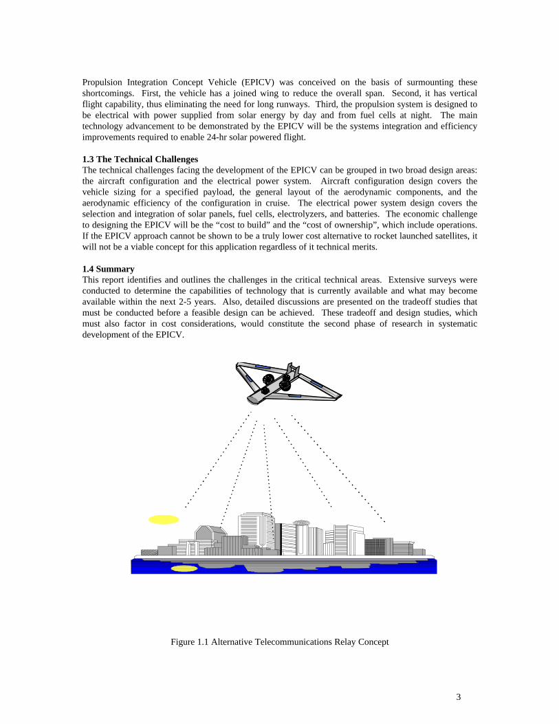
1.2 An Alternative ApproachBecause of the high cost of rocket launched satellites, alternative approaches to providing transmissionrelay capability and expansion of bandwidth are being explored. Among these is the concept of usinghigh altitude, long endurance (HALE) unmanned aircraft to carry telecommunication payloads (see Fig.1.1). Such aircraft would fly station-keeping patterns over large metropolitan areas at altitudes between60,000 ft and 70,000 ft (well above commercial airline traffic). This approach has the advantage of muchlower launch costs. It offers a new operating scenario where a flight system could be launched with littlemore than a flight plan being filed with the FAA. Thus, the telecommunications industry gains control ofthe launch and tracking of their systems from their own facilities. Additional advantages are that thepayload can be easily retrieved for repairs or upgrades and the air vehicle is reusable. For instance,communications payloads need not be designed with high levels of redundancy. Instead, in the event of afailure, a backup system could be kept on hand and flown in to position above any metropolitan areawithin hours. The failed system would be flown back for repairs then used as the new backup system.
The shortcomings to currently proposed designs include the need for large wing spans (200 ft or more) forefficient cruise, long runways for launching the aircraft, and a long term energy source. The Electric
3
Propulsion Integration Concept Vehicle (EPICV) was conceived on the basis of surmounting theseshortcomings. First, the vehicle has a joined wing to reduce the overall span. Second, it has verticalflight capability, thus eliminating the need for long runways. Third, the propulsion system is designed tobe electrical with power supplied from solar energy by day and from fuel cells at night. The maintechnology advancement to be demonstrated by the EPICV will be the systems integration and efficiencyimprovements required to enable 24-hr solar powered flight.
1.3 The Technical ChallengesThe technical challenges facing the development of the EPICV can be grouped in two broad design areas:the aircraft configuration and the electrical power system. Aircraft configuration design covers thevehicle sizing for a specified payload, the general layout of the aerodynamic components, and theaerodynamic efficiency of the configuration in cruise. The electrical power system design covers theselection and integration of solar panels, fuel cells, electrolyzers, and batteries. The economic challengeto designing the EPICV will be the “cost to build” and the “cost of ownership”, which include operations.If the EPICV approach cannot be shown to be a truly lower cost alternative to rocket launched satellites, itwill not be a viable concept for this application regardless of it technical merits.
1.4 SummaryThis report identifies and outlines the challenges in the critical technical areas. Extensive surveys wereconducted to determine the capabilities of technology that is currently available and what may becomeavailable within the next 2-5 years. Also, detailed discussions are presented on the tradeoff studies thatmust be conducted before a feasible design can be achieved. These tradeoff and design studies, whichmust also factor in cost considerations, would constitute the second phase of research in systematicdevelopment of the EPICV.
Figure 1.1 Alternative Telecommunications Relay Concept

4
SECTION 2
INTEGRATED SYSTEM CONCEPT
EPICV is a novel aircraft in many ways. It combines the characteristics of a vertical takeoff and landing(VTOL) aircraft with those of a high-altitude, long endurance aircraft. Its power system is a highlyintegrated set of components that manages the collection, storage, and conversion of solar energy forcontinuous 24 hour flight. Its design is driven by maximizing the overall system efficiency rather than bymaximizing the efficiency of each individual component. EPICV also incorporates several newtechnologies in areas of electric motors, solar panels, and fuel cells.
2.1 General OverviewFigure 2.1 shows the general arrangement of the EPICV in a Joined Wing configuration for the HALEmission. The core of the vehicle is a VTOL platform with four ducted rotor units. The two larger lateralunits can tilt 90� to give vertical thrust in hover and horizontal thrust in cruise. All four ducted rotorsare based on a novel rim-driven electric motor/rotor unit referred to as the “toroid rotor.” For efficientcruise at high altitude, a set of high aspect ratio joined wings is attached to the core VTOL platform.
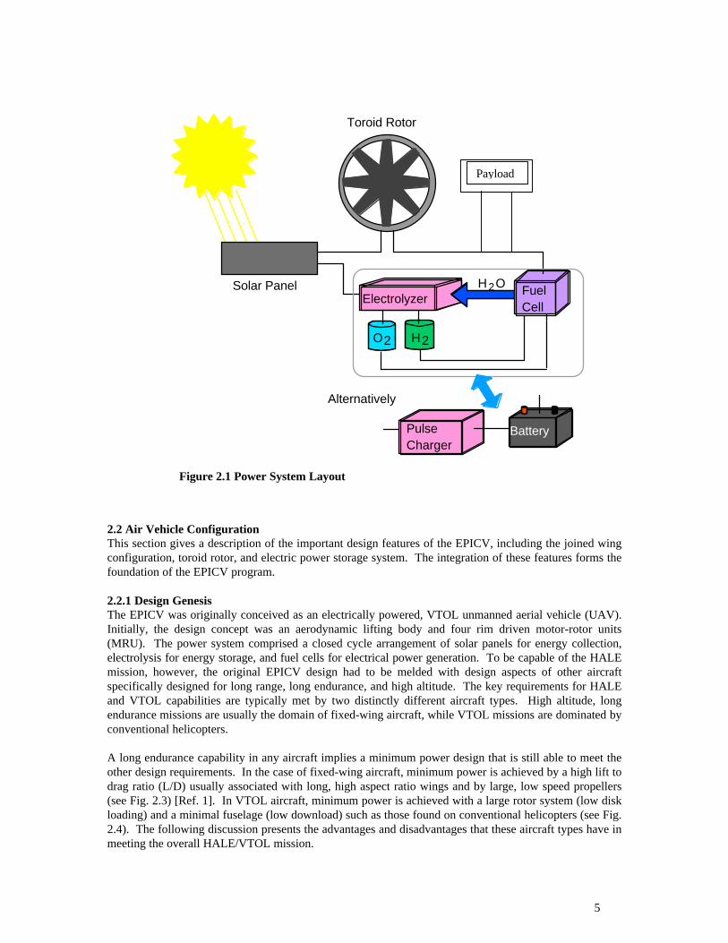
The wings and center body serve a dual function as solar power collection surfaces as their primarystructure role. The upper surface of the vehicle is populated with photovoltaic (PV) cells. Their purposeis to convert solar energy into electrical power, some of which is stored by an electrolyzer while the rest isused directly by the dc motors. Three different power storage/supply concepts should be considered forsustaining flight. Within each concept the basic purpose remains the same—utilize some of the electricalpower directly to drive toroid rotors for vehicle propulsion while the rest is stored for use at night.
The first power storage/supply configuration is a closed loop regenerative fuel cell system shown inFig. 2.2. This is a system where the photovoltaic cells convert solar energy to electrical power, which isused by an electrolyzer to produce hydrogen and oxygen gas [Ref. 1]. The hydrogen and oxygen gases arefed to a regenerative fuel cell system that is designed as an integral part of the vehicle structure. Thesecond power storage and supply concept is similar to the first except that the PV cells are laser energysensitive whereby they convert beamed laser energy to electrical power—supporting regenerative fuel celloperation. The third system concept, is a battery storage system that is similar to the other two. In thiscase, the regenerative fuel cell with electrolyzer is replaced by a network of advanced chemical storagebatteries with an advanced pulse charging algorithm. The electrical power from solar flux is converted tocharging energy that replenishes the batteries via an advanced pulse charging device.
Figure 2.1 General Arrangement of the EPICV
5
2.2 Air Vehicle ConfigurationThis section gives a description of the important design features of the EPICV, including the joined wingconfiguration, toroid rotor, and electric power storage system. The integration of these features forms thefoundation of the EPICV program.
2.2.1 Design GenesisThe EPICV was originally conceived as an electrically powered, VTOL unmanned aerial vehicle (UAV).Initially, the design concept was an aerodynamic lifting body and four rim driven motor-rotor units(MRU). The power system comprised a closed cycle arrangement of solar panels for energy collection,electrolysis for energy storage, and fuel cells for electrical power generation. To be capable of the HALEmission, however, the original EPICV design had to be melded with design aspects of other aircraftspecifically designed for long range, long endurance, and high altitude. The key requirements for HALEand VTOL capabilities are typically met by two distinctly different aircraft types. High altitude, longendurance missions are usually the domain of fixed-wing aircraft, while VTOL missions are dominated byconventional helicopters.
A long endurance capability in any aircraft implies a minimum power design that is still able to meet theother design requirements. In the case of fixed-wing aircraft, minimum power is achieved by a high lift todrag ratio (L/D) usually associated with long, high aspect ratio wings and by large, low speed propellers(see Fig. 2.3) [Ref. 1]. In VTOL aircraft, minimum power is achieved with a large rotor system (low diskloading) and a minimal fuselage (low download) such as those found on conventional helicopters (see Fig.2.4). The following discussion presents the advantages and disadvantages that these aircraft types have inmeeting the overall HALE/VTOL mission.
Toroid Rotor
Solar PanelElectrolyzer
O2 H2
Fuel Cell
H2O
Pulse Charger
Battery
Alternatively
Payload
Figure 2.1 Power System Layout
Payload

6
Figure 2.3 Notional High Aspect Ratio Aircraft for HALE Mission
Figure 2.4 Conventional Helicopter Configuration
2.2.1.1 Configuration ComparisonsThe high aspect ratio fixed-wing configuration has a significant advantage in terms of the lift to dragratio. Ratios as high as 18 (ref. Roskam) are achievable at loiter speeds. The equivalent L/D for typicalhelicopters is on the order of 5 to 6 (Ref. Stepnewski and Prouty). Consequently, an aircraft with a highaspect ratio wing requires significantly less power than one relying on powered lift. The large wing alsoprovides a significant surface area for the solar cells. Other advantages include the fact that aconventional design makes the performance analysis rather straightforward and it uses mechanicallysimple flight controls.
The main disadvantage to the high aspect ratio fixed-wing aircraft is that it is not VTOL capable andrequires dedicated takeoff and landing sites. Also such aircraft are structurally fragile and susceptible towing flutter. In addition, the large wing span makes ground handling difficult.
The main advantage conventional helicopters have is that they are VTOL capable. Their large openrotors represent the minimum power design for hovering. The narrow fuselage minimizes the downloadon the vehicle to improve hover efficiency. However, with respect to the HALE portion of the mission,conventional helicopters have several disadvantages. The low lift to drag ratio previously mentionedmeans they are not particularly efficient in cruise. Furthermore, their small fuselages present nosignificant surface area for mounting solar cells. The large diameter rotors that they require for efficienthovering cannot be shrouded in a practical manner and are, therefore, dangerous to ground personnel.They also require complex rotor hub mechanisms such as swashplates and pitch links for attitude controland auxiliary rotors for anti-torque and directional control.
7
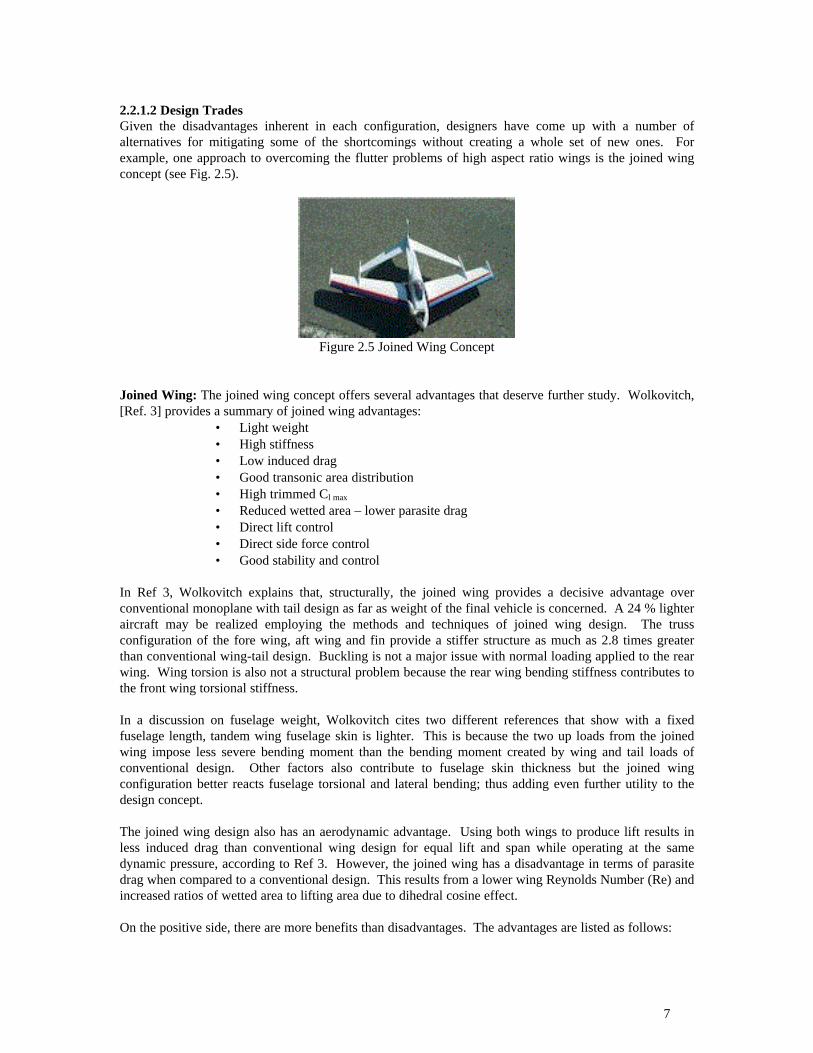
2.2.1.2 Design TradesGiven the disadvantages inherent in each configuration, designers have come up with a number ofalternatives for mitigating some of the shortcomings without creating a whole set of new ones. Forexample, one approach to overcoming the flutter problems of high aspect ratio wings is the joined wingconcept (see Fig. 2.5).
Figure 2.5 Joined Wing Concept
Joined Wing: The joined wing concept offers several advantages that deserve further study. Wolkovitch,[Ref. 3] provides a summary of joined wing advantages:
• Light weight• High stiffness• Low induced drag• Good transonic area distribution• High trimmed Cl max
• Reduced wetted area – lower parasite drag• Direct lift control• Direct side force control• Good stability and control
In Ref 3, Wolkovitch explains that, structurally, the joined wing provides a decisive advantage overconventional monoplane with tail design as far as weight of the final vehicle is concerned. A 24 % lighteraircraft may be realized employing the methods and techniques of joined wing design. The trussconfiguration of the fore wing, aft wing and fin provide a stiffer structure as much as 2.8 times greaterthan conventional wing-tail design. Buckling is not a major issue with normal loading applied to the rearwing. Wing torsion is also not a structural problem because the rear wing bending stiffness contributes tothe front wing torsional stiffness.
In a discussion on fuselage weight, Wolkovitch cites two different references that show with a fixedfuselage length, tandem wing fuselage skin is lighter. This is because the two up loads from the joinedwing impose less severe bending moment than the bending moment created by wing and tail loads ofconventional design. Other factors also contribute to fuselage skin thickness but the joined wingconfiguration better reacts fuselage torsional and lateral bending; thus adding even further utility to thedesign concept.
The joined wing design also has an aerodynamic advantage. Using both wings to produce lift results inless induced drag than conventional wing design for equal lift and span while operating at the samedynamic pressure, according to Ref 3. However, the joined wing has a disadvantage in terms of parasitedrag when compared to a conventional design. This results from a lower wing Reynolds Number (Re) andincreased ratios of wetted area to lifting area due to dihedral cosine effect.
On the positive side, there are more benefits than disadvantages. The advantages are listed as follows:

8
1. Reduced wing area due to high trimmed Clmax
1. Reduced fuselage wetted area due to reduced length2. Improved wing fuselage interaction3. Smooth fairing of landing gear4. Fin-nacelle integration
The wing Re comparison shows that the joined wing has a lower Re than a conventional configuration,which could be as much as 40% lower according to Ref 3. This point does raise a possible considerationfor laminar flow control since laminar flow control is easier at lower Re.
Air Foil Design: The joined wing being swept aft creates a flow where the boundary layer is swept backthus increasing Clmax near the wing root according to Wolkovitch. He does point out that sharp noseairfoils are beneficial in that they may enable shed vortices, which will migrate outward along the wingleading edge increasing vorticity; thus increasing lift.
Control: The stall characteristics of the joined wing models and wind tunnel tests indicate the stallcharacteristics are good—no adverse attitudes such as “wings dipping” at stall have appeared. Adjustingpositive or negative dihedral of front and rear wing can influence lateral stability of joined wing design.The spiral tendency of the joined wing design shows no tendency to dutch roll. Directional stability isgood due to the effect of attaching the rear wing to the vertical fin. Control of the joined wing is versatileand can be easily achieved if each half of the wing is equipped with a control surface. Any desired controlconfiguration can be achieved by coupling the individual control surfaces.
Ducted Rotors: For helicopters, some of the efficiency lost by reducing the rotor diameter can be regainedby placing the rotor in a duct (see Fig. 2.6). This has the added advantage of making the vehicle safer forground personnel. By imbedding the duct in the fuselage there is no download on the body. If multiplerotors are used, it is possible to balance torque without an auxiliary tail rotor; thus all the power goes intoproducing vertical thrust. It is also possible to control the aircraft without complex rotor hubs by usingthrust variation on the different rotors. The drawbacks are that a ducted rotor will still not be as efficientas a much larger open rotor and the ducts produce drag in forward flight. Also, if the ducted rotorsremain oriented vertically in forward flight they tend to suffer from pitch stability problems due to flowseparation over the lip of the duct.
Figure 2.6 Ducted Rotor Air Vehicle (Sikorsky Cypher)
Tilting Rotors: A concept for improving the efficiency of rotorcraft in forward flight is tilting the rotorsystem such as is done on the tiltrotor (Fig. 2.7) and tilt-duct (Fig. 2.8) configurations. The advantage isthat efficiency is greatly improved by maintaining the rotor system in axial flight. This also allows higherforward speeds and wing-borne lift. With wing lift, the power requirement for the rotor system is reduced,permitting the rotor to be turned at a slower speed. The disadvantage to this concept is, of course, themechanical complexity involved in tilting the rotor system. There is also a weight penalty for the tiltmechanism.

9
Figure 2.7 Tiltrotor Aircraft (XV-15)
Figure 2.8 Tilt-Duct Aircraft (Doak VZ-4)
2.2.1.3 Applying the Design Trades to the EPICVTo perform the HALE/VTOL mission, the original VTOL design was modified to include some of thedesign features described in the previous discussion. Since vertical thrusters are not as efficient as wingsfor maintaining lift in forward flight, the goal is to transition the vehicle from thruster-borne flight towing-borne flight as quickly as possible. Toward this end, the modified EPICV design includes a set ofjoined-wings (see Fig. 2.1). In addition, the two lateral MRUs are relocated outboard of the fuselage,greatly increased in diameter, and made tiltable. These MRUs will be the primary source for vertical liftand forward propulsion. The fore and aft MRUs were reduced in size slightly and are used primarily forpitch control in VTOL mode. As a secondary function, they can supply additional vertical thrust in hoverand vertical climb. A horizontal stabilizer spanning the vertical tails was added to provide pitch stabilityand control and to reinforce the vertical tails to which the joined-wings are attached.
Mission flexibility for this unique type of air vehicle is preserved by making the large joined wingsdetachable. The remaining core vehicle, which contains all the avionics, payload, fuel cells, andpropulsion system, will be capable of short range VTOL missions without the encumbrance of the largejoined wings.
10
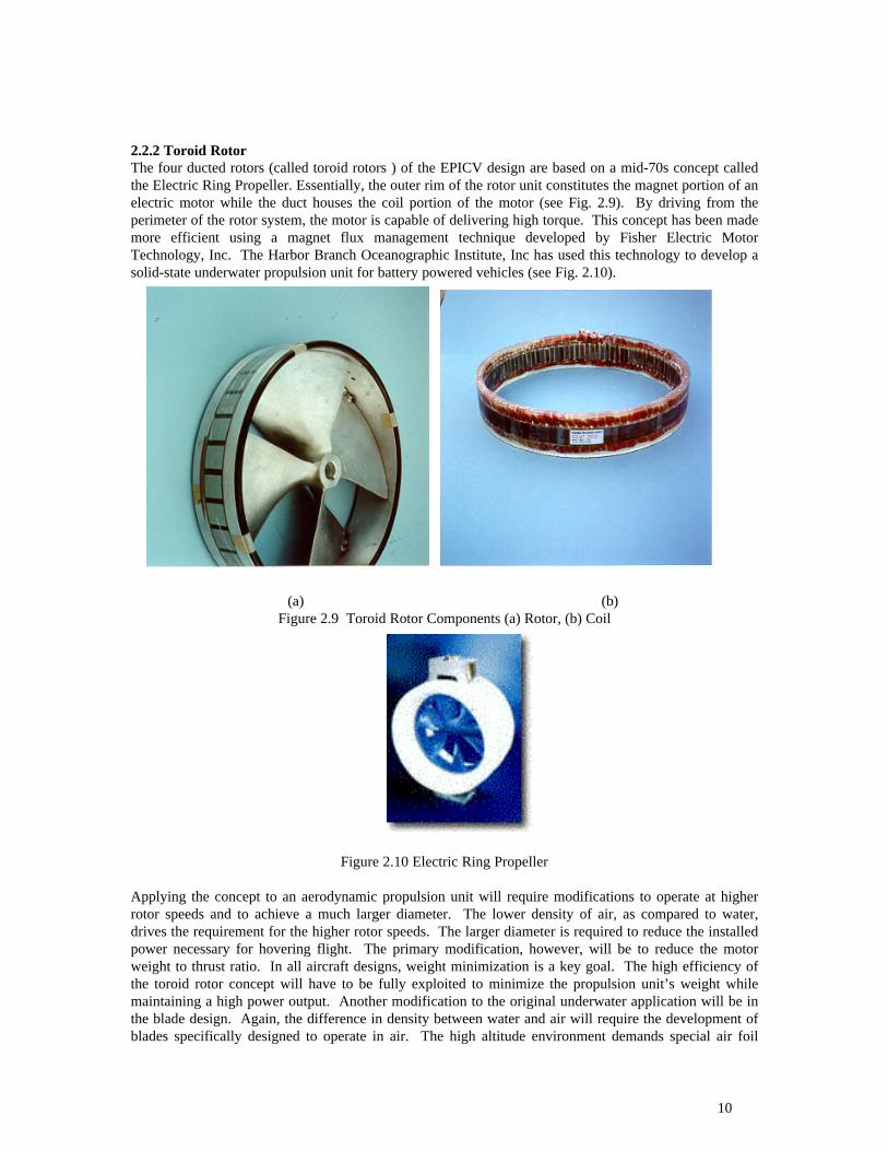
2.2.2 Toroid RotorThe four ducted rotors (called toroid rotors ) of the EPICV design are based on a mid-70s concept calledthe Electric Ring Propeller. Essentially, the outer rim of the rotor unit constitutes the magnet portion of anelectric motor while the duct houses the coil portion of the motor (see Fig. 2.9). By driving from theperimeter of the rotor system, the motor is capable of delivering high torque. This concept has been mademore efficient using a magnet flux management technique developed by Fisher Electric MotorTechnology, Inc. The Harbor Branch Oceanographic Institute, Inc has used this technology to develop asolid-state underwater propulsion unit for battery powered vehicles (see Fig. 2.10).
(a) (b)Figure 2.9 Toroid Rotor Components (a) Rotor, (b) Coil
Figure 2.10 Electric Ring Propeller
Applying the concept to an aerodynamic propulsion unit will require modifications to operate at higherrotor speeds and to achieve a much larger diameter. The lower density of air, as compared to water,drives the requirement for the higher rotor speeds. The larger diameter is required to reduce the installedpower necessary for hovering flight. The primary modification, however, will be to reduce the motorweight to thrust ratio. In all aircraft designs, weight minimization is a key goal. The high efficiency ofthe toroid rotor concept will have to be fully exploited to minimize the propulsion unit’s weight whilemaintaining a high power output. Another modification to the original underwater application will be inthe blade design. Again, the difference in density between water and air will require the development ofblades specifically designed to operate in air. The high altitude environment demands special air foil

11
design. A trade-off must be achieved to come up with blade air foil design that can effectively operate atlow altitude and by change in flow environment via rpm variation or mechanical reconfiguration via“smart structure” technology.
2.3 Power System
2.3.1 System OverviewFor long duration loiter missions where solar energy will be used as the sustaining energy source, theupper surfaces of the vehicle will be used as mounting points for the photovoltaic cell arrays. In today’sapplications these cells are mounted directly to the upper surface and attached directly to the structuralsurfaces. For the contemplated system, an electrolyzer will use the converted solar energy to producehydrogen and oxygen. Fuel cells dispersed throughout the vehicle structure receive the hydrogen andoxygen and convert it into electricity for the toroid motors.
2.3.2 Solar CellsThe three principal suppliers of space quality (lightweight) solar cells in the world are: SHARP,TECHSTAR and Spectrolab, a division of Hughes. Table 1 shows information gathered on thecommercial specifications of currently available solar cells. Note that the weight per area is based on cellweight; thus, mounted module weight will be somewhat higher. Using the information from Pathfinder,as cited by reference [Ref 17] p5, the module fabrication adds 280 g./m2 of weight and the cell packingdensity is only 90%. Note that calculations in Table 1 were made using AM0 sunlight of 1353 W/m2
which is the sunlight spectral intensity in space. In addition, Table 1 calculations do not take into accountoperating temperature [Ref. 4]. Current NASA studies indicate that the power delivered from cells wasoften over-estimated because of temperature gradients of up to 10 degrees from the end of the wing to thecenter, thus causing reduced efficiency. Losses for silicon are on the order of 2.2 mV/oC with a gain of 22µA/cm2. For multi-junction silicon and GaAs, these numbers are lower.
Using the table, a decision can be made about the primary design criteria: weight, area, and price. At thisstage of analysis, the highest efficiency cells with the lowest weight will over-ride cost considerations fortwo reasons. First, because of the limited surface area on the air vehicle, efficiency per pound isparamount. Second, because of the fairly long lead time to the construction of a demonstration vehicle(two years or more), the cost per area is expected to come down for any given level of efficiency. Thisapproach will at least permit the design of a functional system that will allow further investigation of thetechnical merit of the overall system. In this regard, future prospects for the 35-40% efficient cells fromSpectrolab warrant tracking. However, the optimistic time frame appears to be more like 3-5 years sincethese are not yet working devices and Hughes has just started the development.
It is very apparent that the design criteria for terrestrial and space cells are optimized for differentparameters. Weight is the primary area of concern for aerospace applications. Trying to use any of thelower cost terrestrial applications burdens the vehicle with specific energy requirements that defeat theutility of the design. However, lack of need for radiation protection is a primary difference between thedesign criteria for space applications and high altitude vehicles. There appears to be at least onetechnology, multilayer thin film polycrystalline silicon, that is of fairly high efficiency, with the promiseof low cost. It is not likely to be useful for space applications because of the lower radiation protection,and it has therefore been developed for terrestrial applications, with little concern over weight issues. Ifthe potential market for high-altitude-in-atmosphere aircraft is sufficient, research into lightweight, non-space quality cells, such as described herein, and may warrant research on the thin film cells for HALEapplication.
As part of the preliminary research into solar cell technology, several nationally recognized experts in thefield were consulted. Among these was Mr. Dennis Flood from NASA Power Systems, Lewis ResearchCenter. The following are some of the insights Mr. Flood had to offer:
12
The Ames Research/Aerovironment team is using silicon (Si) or gallium arsenide (GaAs)space solar cells. In the near term, this is all that is available. In the last 4 years, the spacemarket has shifted from using 10% GaAs to using 90% GaAs, with the balance beingsilicon. U.S. suppliers have effectively stopped making Si space cells. It appears as if U.S.suppliers have stopped innovating on space silicon, and though they may still supply it, it isnot the best performance available. The best Si cells are from SHARP Corporation in Japan,and they dominate any sales of space silicon. There is basically no supply in Europe rightnow. They stuck with the older Si technology, and are now 10 years behind in developmentof GaAs technologies.
The estimated costs for commercial space solar cells are as follows. The best Si cells(SHARP) are about $100/W. GaAs cells are $200-$300/W depending on customerqualifications and quantity ordered. Multi-band gap cells with 22%+ efficiency are $400-$1000/W. China is increasingly producing the older, space station 14% efficient Si cells for~$100/W, but in large area (8x8) which saves on module assembly costs.
Based on this information, a typical array will cost $1500-2000/W including at least $1000/W to mountthe cells on the surface of the vehicle. Using lower grade labor (i.e., graduate students) for assembly canreduce this cost.
From another subject matter expert, Mr. Dave Bents of the NASA Glenn Research Center (formerlyLewis), it was learned that the Martian atmosphere is similar to Earth’s at 100,000-ft altitude.Consequently, the attributes of a HALE UAV may have application in UAV design for exploration ofMars.
Several emerging developments in solar cell technology may be applicable to a commercially viableEPICV. An ideal application would be a monolithic integrated thin film solar blanket. This has beenpictured in a mock up for a lunar landing where the cells are on a flexible blanket that can be erected likea tent and provide power and shielding. The most mature thin film technology producer is Iowa ThinFilms. They have an amorphous cell on Kapton with about 5% efficiency. The contacts are screen-printed silver paste, which is not space qualified, but it might hold up at 100,000 feet. They used a rollprocess with 14 inches wide by 1000 ft cells. Any combination of voltage, current, and size can be made.
Unisolar can make 8-10% efficiency cells on a silicon substrate. This is lightweight compared to glassand can be etched to .5 mil thickness for further weight savings. They have done this for some 1 ft x 1 ftcells for use on the space station, but not in larger areas. Cost for this technology is unknown.
Finally, Global Solar in Arizona is attempting to make CuInGaSe2 (CIGS) on titanium foil or a polyamidesubstrate. Their process is not yet reliable, but the goal is to produce rollable cells 10% efficient (in spaceconditions) at 14 inches by 1000 ft.
2.3.3 Fuel Cell /Electrolyzer.Significant research is currently being conducted in fuel cell and electrolyzer development, with severalapproaches are being taken in their application. Stand alone or distinct fuel cell functions by combininghydrogen and oxygen to generate electrical power, water, and waste heat. An electrolyzer generateshydrogen and oxygen from the dissociation of water using a dc electric current. Some fuel cell designscan be operated in reverse process and, thereby, serve a dual role as an electrolyzer. Such dual modedevices are referred to as unitized fuel cells. An integrated system of a fuel cell, electrolyzer, gas storagecontainers, and solar panels is known as a regenerative fuel cell.
Of the five main types of fuel cells, NASA has long used ones using alkaline potassium hydroxide as theelectrolyte on space missions. These cells can achieve power-generating efficiencies of up to 70%,although they have been too costly for commercial applications. Fuel cells with a proton exchange

13
membrane (PEM) as the electrolyte are another type that operate at relatively low temperatures (~ 200�F) and have a high power density. The U.S. Department of Energy considers the PEM fuel cell to be theprimary candidate for light-duty vehicles and potentially for much smaller applications.
NASA has been working in fuel cell development with Proton Energy for unitized regenerative space fuelcell systems and with Lynntech for distinct cells. Both of these projects are sponsored by SBIR grants.Aerovironment and Dreiden Center are also developing fuel cell technology. At present, no workinglightweight regenerative fuel cells exist, but Proton Energy’s web site does list 400 Wh/kg as a currentpower density for a PEM type fuel cell. Given this level of power density, it may be worth consideringthis fuel cell for application in a closed loop system demonstration.
In addition to their unitized fuel cell developments, Proton Energy Systems supplies commercialelectrolyzers. They have already supplied an electrolyzer to NASA Lewis for some testing of gas handlingsystems. Proton Energy Systems’ electrolyzer is also based on the PEM technique. One design advantageof PEM electrolyzers is that they put out pressurized hydrogen (easily 400 psi), so no compressionequipment is necessary. The hydrogen is stored in pressurized composite tanks. It is not known whatdesign considerations are being used for oxygen storage/compression, or if the plan is to use atmosphericoxygen. Lack of oxygen at high altitude would lead to a consideration of some type of storage tank.
Unitized fuel cells are attractive from a design efficiency view in that a single device can be used toperform two functions. However, design considerations for a unitized fuel cell include matching thevoltage requirements for its two roles. The fuel cell operating voltage is 1/2 the voltage of the electrolyzeroperating voltage for a given cell. The difference must be compensated for through power conditioning.Another problem is one that Proton is having with its unitized fuel cell. The carbon paper used in theMembrane Electrode Assembly (MEA) is degrading when the stack operates as a fuel cell. In otherwords, it has not been as simple as just feeding gases through a standard or custom electrolyzer togenerate electricity.
A phase II SBIR contract for a design of a lightweight electrolyzer/fuel cell combination using discretecells for each rather than unitized cells will commence in the very near future. With the level of activityongoing it appears that progress is being made in the fuel cell development area. This leads to theprojection that the fuel cell technology will be ready to support the development of a vehicle such asEPICV in the next 3 to 5 years.
2.3.4 Battery Storage/Rapid RechargeAn alternative to a fuel cell/electrolyzer combination for power storage is a battery/recharger system.Recent research at Georgia Tech has produced advanced battery charging technology that has potentialapplication to UAV systems. An advanced pulse-charging algorithm has been demonstrated on nickelmetal hydride (NMH) and lead acid (LA) batteries. The premise of the advanced pulse charge is quitesimple. By structuring a charge waveform (input energy) that is correlated with the state-of-charge (SOC)of the battery a highly efficient charge process can be accomplished. The batteries can be charged back to100% SOC without the hazard of “thermal runaway” (i.e., melting the battery down). The cycle life forthe battery is enhanced due to the lack of heat stress which decreases cycle life and the over-charge andunder-charge phenomenon which also can influence cycle life. A further dimension to the advancedbattery charging technology is the battery management system (BMS). The BMS is necessary to properlymanage the charge process as well as to provide network control over the battery banks that function on aload share basis.
The battery storage system while having a lower power density than a regenerative fuel cell system or abeamed energy conversion system does offer some benefit over conventional design approaches. Aircraftthat are battery powered (with rechargeable capability) could fly for relatively long periods of time basedupon cycle life of the batteries. With proper BMS management of the charge process and temperaturecontrol, battery cycle life will be near the maximum design capability. Typically this could be 800 to 1,000 cycles for a 32 amp-hour battery.

14
High-power electronics will not be required to manage the waveform for recharging. The properwaveform can be implemented in low power circuits and signal conditioned. Separate circuits then boostthe strength of the charge pulse to the required levels. Since the BMS controller would be designed so thateach battery is charged individually, high voltages associated with pack charging are avoided. Therefore,electrical power from PV cells with some power conditioning is capable of charging battery packssupporting the electrical propulsion system. It should be noted that because of its lower power density,toroid rotor with its minimum electrical power consumption becomes an attractive performer. Furtheranalytical work is needed to sharpen the perspective on whether an advantage may be found in usingbattery storage in conjunction with a toroid motor/rotor configuration.

15
Table 1.
Comercial Solar Cell Specifications
Manufacturer Product Type Efficiency Weight mg/cm 2 Price per cm 2
(note 1)
Thickness(µ m)
Watts/m 2
at AM0(note 2)
Watts/kg Price/m 2 Price/W
Techstar 1 Silicon 12.5% 55 $1.50 200 169 308 $15,000.00 $88.69Techstar 2 Silicon BSFR 14.7% 55 $1.96 200 199 362 $19,600.00 $98.55Techstar 3 GaAs-Inventory 17.5% 93 $6.50 140 237 255 $65,000.00 $274.52Techstar 4 GaAs 19.0% 93 $8.00 140 257 276 $80,000.00 $311.20Techstar 5 MultiJunction 23.0% 93 $9.00 140 311 335 $90,000.00 $289.21Spectrolab 6 K4702 Siilicon 13.3% 55 200 180 327Spectrolab 7 K4710 Silicon 12.3% 55 200 166 303Spectrolab 8 K6700B Silicon 13.7% 24 62 185 772Spectrolab 9 GaAs/Ge-Single Junction 19.0% 100 175 257 257Spectrolab 10 GaAs/Ge-Single Junction 19.0% 80 140 257 321Spectrolab 11 GaInP2/GaAs/Ge-Dual Junction 21.5% 100 175 291 291Spectrolab 12 GaInP2/GaAs/Ge-Dual Junction 21.5% 80 140 291 364Spectrolab 13 GaInP2/GaAs/Ge-Triple Junction 24.0% 80 $10.07 140 325 406 $100,663.20 $310.00Spectrolab 14 GaInP2/GaAs/Ge-Triple Junction 26.0% 80 $10.91 140 352 440 $109,051.80 $310.00Spectrolab (note 3) 15 DEVELOPMENT GaInP2/GaAs/Ge-Triple Junction 26.0% 58 102 352 607Spectrolab (note 4) 16 DEVELOPMENT Four Junction Cells 35.0% 100 474 473.55SHARP 17 Light weight Silicon 17.0% 17 230 1353
Sample requirements for 14800 Watts of Power Module Estimate Data (note 5)Enter Power Requirements (watts) 14800Manufacturer Weight (kg) for
14800 Watts/kgArea (m2 ) for 14800Watts
Price ($) for14800 Watts
Manufacturer
Weight ofcircuits,laminant,etc.(kg/m2)(note 5)
Area (m2)for 14800Watts at90%PackingDensity
Techstar 1 48.1300813 87.50923873 $1,312,639 Techstar 1 0.28 97.23249Techstar 2 40.92693988 74.41261797 $1,458,487 Techstar 2 0.28 82.68069Techstar 3 58.13113716 62.50659909 $4,062,929 Techstar 3 0.28 69.45178Techstar 4 53.54183685 57.57186758 $4,605,749 Techstar 4 0.28 63.96874Techstar 5 44.23021305 47.55936887 $4,280,343 Techstar 5 0.28 52.84374Spectrolab 6 45.23503882 82.24552512 Spectrolab 6 0.28 91.38392Spectrolab 7 48.91268425 88.93215318 Spectrolab 7 0.28 98.8135Spectrolab 8 19.16260702 79.84419592 Spectrolab 8 0.28 88.71577Spectrolab 9 57.57186758 57.57186758 Spectrolab 9 0.28 63.96874Spectrolab 10 46.05749407 57.57186758 Spectrolab 10 0.28 63.96874Spectrolab 11 50.87746438 50.87746438 Spectrolab 11 0.28 56.53052Spectrolab 12 40.7019715 50.87746438 Spectrolab 12 0.28 56.53052Spectrolab 13 36.4621828 45.5777285 $4,588,000 Spectrolab 13 0.28 50.64192Spectrolab 14 33.65739951 42.07174939 $4,588,000 Spectrolab 14 0.28 46.74639Spectrolab 15 24.40161465 42.07174939 Spectrolab 15 0.28 46.74639Spectrolab 16 31.25329955 31.25329955 Spectrolab 16 0.28 34.72589SHARP 17 10.93865484 64.34502848 SHARP 17 0.28 71.49448
NOTES1) Price Data are working estimates not price quotes
2) Calculations based on cells only at AMO sunlight (1.353 kW/m 2 )3) 102 µ m (4 mil) cells may be possible4) 35% Cells have not been demonstrated as a working device5) Packing Density and Module weight are from reference [13]

16
SECTION 3TECHNICAL CHALLENGES
All of the challenges that are normally faced in a new conceptual design are present for the EPICV. Toscope the problem down to manageable size, three aspects of this technical challenge were identified. Thethree key aspects of the technical challenge are:
1. Balancing power required against power available2. Designing for a sufficient payload margin3. Obtaining the maximum aeromechanical efficiency
3.1 Power Required/Power AvailableThe power required to raise an aerial vehicle to 70k-ft altitude can be broken down into segments. Thefirst segment is the takeoff. In this segment, the vehicle is accelerated forward until a sufficient airspeedis reached that will sustain wing borne flight. Next the climb segment occurs. Power necessary to sustainthe vehicle’s forward speed plus the power to climb is required in this phase. In addition to the power toovercome gravity for take off and climb, there must be sufficient power to overcome drag. Induced,parasite, and skin friction drag are the components of power requirement where certain designcharacteristics are more efficient than others. Of course, in any vehicle design tradeoff, efficiency issought within the parameters of the mission scenario. For takeoff and climb the considerations arestraightforward—minimize power required for these phases of flight minimize weight and also toconserve power for other aspects of mission performance.
3.1.1 Takeoff and Climb PowerFor takeoff and climb power required, the EPICV flight parameters for weight and drag appear to be mostefficiently addressed with a joined wing design. In this research it was found that the joined wing designconcept specifically offers an advantage over conventional monoplane and tail design for weight, induceddrag, and skin friction drag. Reference 3, specifically addressed these areas and reports the advantages ofthe joined wing design over a conventional configuration.
3.1.2 Cruise PowerIn the cruise phase of flight, induced drag and skin friction drag are key parameters for determining howmuch power is required for maximum endurance. For the HALE mission this process is complicated bythe fact that the vehicle will be in darkness for a portion of each 24 hour period. Energy reserves must bereplenished to be available during the periods of darkness. Electrical power harvest and storage arecritical to the success of this facet of the mission performance.
3.1.3 24-Hour OperationOn the issue of continuous 24 hour operation, it is important to keep in mind that the overall weight of thevehicle is directly affected by the amount of power storage capacity that is necessary for day and nightoperation. Two facets of this challenge are important to highlight:
• During daylight power is required for flight sustainment, payload operation and forreplenishment of the stored energy which is consumed during the night.
• Vehicle design is impacted by the weight of the power storage system—systemweight dramatically affects takeoff and climb power required—which further affectsthe weight of the propulsion unit.
More will be said about the innovation of the EPICV design to specifically address these aspects of systemperformance requirement.
17
3.1.4 Solar Powered UAV ResearchIn previous research, NASA investigators analyzed the impact of subsystem technology on an electricUAV’s size. Ref. 1 presented an analysis of the impact of power system components and missionrequirements on the size of solar powered HALE aircraft. An important finding from this work was therelationship of the energy storage system performance to the vehicle’s size. The impact of PV cellperformance was found to be less important. The results of this analysis showed that the specific energyvalue for the storage system must be in the range of 250-500 Whr/kg to support useful missions. One ofthe stated goals of the cited paper was to examine the remaining power system deficiencies that stand inthe way of successful solar powered UAVs. It was meaningful to the present analysis that the results ofthe NASA investigation so clearly identified power storage (fuel cell/electrolyzer) as a major constraint onelectric UAV development. A key finding in the cited analysis was that fuel cell capacity had a far greaterinfluence on wing aspect ratio than did the efficiency of the PV cell system. There is no indication fromthe information reviewed in Ref. 1 that any investigation was conducted into improving the powerconsumption efficiency of the propeller/power plant technology. It was mentioned that the motors weresamarium electric motors with approximately 90% efficiency. Therefore, it is evident that a challengestill exists for coming up with a motor/rotor combination that shows clear advantage over the presenttechnology.
3.1.5 Fuel Cell/Electrolyzer DevelopmentFuel cell/electrolyzer state-of-the-art is lagging behind the 400Kwh/kg level reported in the NASAresearch. Consequently, the challenge is to assess the likelihood that current development efforts will bemature enough in three to five years to support a credible system development. Or, if there is a path fordevelopment of a system with less specific energy storage capability, the challenge is to optimize thepropulsion system requirements to achieve a compatible power required/power available match in themission performance scenario.
3.1.6 Attracting Industry InvolvementThe ultimate technical challenge is to create an operating paradigm that is attractive to industry. In otherwords, create a technology, which can be adapted and used comfortably by industry in exploiting theatmosphere-space continuum for commercial enterprise. The present paradigm for telecommunicationsatellite technology is to rocket launch a satellite and collect revenue based on its throughput capability.The rocket launch phase of this scenario is very expensive to industry. Therefore, the challenge at hand isto create a technology that will enable industry to build their payloads and UAV flight platformsconcurrently. They would then launch the hardware from their own industrial facilities with no morerequirement than having to file a flight plan with the FAA for the ascent phase of the flight. Attributes ofa proposed system will be discussed in the innovation section.
3.2 Payload MarginIn keeping with the goal to create a flight system which has appeal to industry, the payload to grossweight fraction must be as high as possible. Industry must be able to make the business case that usingthe new technology shows a clear and distinct return on investment. One major market area that would bethe fulcrum for getting industry involvement is wireless communication for major metropolitan centerssuch as: New York, Los Angeles, Chicago, and Atlanta. An EPICV type of vehicle that could be launchedand flown at high altitude over the region and act as a communication switching and relay platform hasgreat economic value to industry. Increased bandwidth is already a telecommunication industry goal.Huge sums of money are being invested in fiber optic cable that will address the networked systemtechnology for in-home entertainment and shopping. Services such wireless data and voice remain aschallenges for industry.
3.2.1 Margin for Payload WeightFurther research is needed to develop insights into the payload requirements that support futuretelecommunication systems technology. These requirements must then be used to size a UAV capable ofcarrying the desired payload above a major population center.

18
3.2.2 Power Margin for Payload OperationThe HALE mission presents the challenge of 24-hour continuous operations. The problem of energygeneration and storage for both flight sustainment and payload operation must be addressed withinnovative approaches. In the innovation section a functional concept will be presented that allows thepower storage requirement to be dramatically reduced.
3.3 Aeromechanical EfficiencyThe approach to achieving a highly efficient aeromechanical design is more involved than just combiningthe most efficient subsystems and components into one system. For example, the highest efficiency solarcells may only be available in the form of inflexible panels. Applying these panels to the wing wouldresult in a faceted surface, which would suffer from severe turbulent flow and high drag. Consequently,more power would be required to pull the aircraft through the air. If lower efficiency thin film solar cellscould be used on a smooth, low drag wing, the cruise power required would be lower and it is possible thatthe overall system efficiency would be higher.
Sorting out the effects of each component’s characteristics on the overall system is a significantoptimization challenge. For example, the efficiency of a fuel cell must be traded off against the weightimpact it has on the total aircraft and how the overall weight affects the power required for flight. Thus,an iterative process must be established to evaluate the numerous possible design permutations. Theprocess must account for the interdependencies that in some cases are counter productive in a multi-variable problem solution context. An example is in optimization of surface area for solar energy capture-- skin friction drag for the vehicle is increased which increases power required, that may potentially addweight to the propulsion system. Technical approaches supported by analytical methods are needed tosupport engineering assessments of design tradeoffs.
SECTION 4TECHNICAL INNOVATION
The previous sections have described a baseline vision of the EPICV. It is fully recognized that, at thisstage, there is not enough information on the various technologies to ensure an accurate feasibilityassessment of the design approach. Consequently, several innovative technologies will be investigated foruse as necessary to achieve the HALE telecommunications relay mission. This section describes thoseareas of innovation and how they might impact the conceptual design.
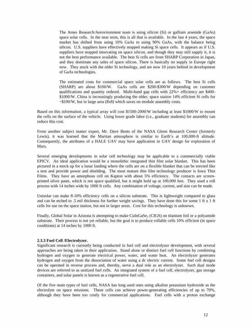
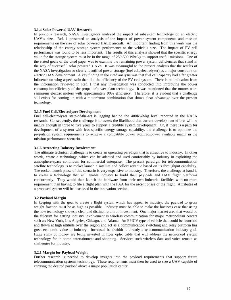
4.1 Toroid RotorThe application of toroid rotors to aerodynamic propulsion is a new concept. Toroid motor/rotor units(MRUs) are currently used in the submersible vehicle industry. Fisher Electronics makes the underwatersystems and the vehicle in Figure 4.1 that was constructed for the Navy using toroid MRUs.
19
Figure 4.1 Underwater Craft with Toroid Motor/rotor Units
4.1.1 Key AdvantagesThe primary advantage of the toroid MRU concept is that it has a significant mechanical advantage bybeing driven from the rotor rim. Consequently, it is capable of delivering high torque. This advantagebecomes apparent when considering how power and weight are traded off in rotorcraft design.
The power required sustaining vertical flight is composed of two major components: induced power andprofile power. Induced power is the power required to pump enough air downward to offset the vehicle’sweight. This power can be determined from a simple momentum model of the rotor system andconstitutes about 60%-70% of the power required to hover. The profile power represents the effortrequired to drag the blade’s airfoil through the air. This power is proportional to the square of the blade’stip speed. Typical blade tip speeds range from 500 ft/sec to 800 ft/sec. At higher tip speeds the rotorbegins to experience high drag problems due to compressibility effects.
In conventional designs, power is supplied to the rotor by a high speed, low torque engine (or motor).These types of powerplants usually operate most efficiently at 10,000 rpm or more. Driving a rotor of anyconsequential size directly at these speeds would result in unacceptably high tip speeds. For this reason, atransmission is used to reduce the powerplant’s output speed and raise its torque. In small conventionalhelicopters, transmission reduction ratios on the order of 10:1 – 15:1 are common. This requires a heavytransmission that adds to the overall weight of the vehicle and, thus, requires more power to lift.
Because of its inherent high torque capability, it may be possible to operate the toroid rotor at low enoughspeeds without the need for a transmission. This represents a significant weight savings and improvementin overall efficiency. Furthermore, because the electric motor is distributed around the duct, nocomponents are located beneath the rotor and incurring a download penalty. Finally, some level ofstructural efficiency is gained by using the duct for two purposes – aerodynamic control of the rotor inflowand structural support of the electric motor.
20
Ducted rotors such as the toroid rotor also have an aerodynamic advantage over open rotors in producingthrust. Near the tips of open rotor blades the high pressure air on the bottom surface of the blade rollsaround the tip to the low pressure region above the blade. This creates what is known as a tip vortexwhich reduces the rotor’s induced power efficiency. In a ducted rotor, the strength of the tip vortex isgreatly reduced because the clearance between the blade tip and wall is very small (0, in fact, for thetoroid rotor). As a result, for an open rotor and ducted rotor of equal radius and induced power level, theducted rotor will produce 26% more thrust than the open rotor. Alternatively, for the same radius andthrust level, the ducted rotor will require 30% less induced power than the open rotor.
Even though it has numerous advantages, the toroid rotor design does have a few disadvantages. One isthe drag penalty incurred by dragging the duct through the air during cruise. While tilting the duct toalign it with the flow greatly reduces the drag penalty, the impact on cruise efficiency must still beassessed. Other disadvantages are design issues regarding the need for large diameter thrust bearings andlubrication. These are not considered serious and will be addressed during the detailed feasibility andpreliminary design studies.
4.2 Integrated VTOL and Fixed-Wing Flight ControlsThe EPICV is required to operate in two extreme (and conflicting) flight modes. For takeoff, the aircraftmust be able to hover and climb vertically. It must then transition to forward flight mode and proceed to ahigh altitude, long endurance flight regime. Flight control in the forward flight fixed-wing mode will beaccomplished with conventional aerodynamic control surfaces - ailerons, elevator, and rudders.Conventional fixed-wing controls were chosen because they are a low risk, low cost, and low powerconsumption approach. In contrast, the optimal technique for VTOL mode control is not so clear cut.Appendix A presents a review of the control concepts employed by various VTOL aircraft to illustratesome of the tradeoffs that must be made. The conclusion of the review is that a four-rotor design appearsto offer the advantages of mechanical simplicity and vertical thrust efficiency. In this arrangement, theforward and aft rotors are used for pitch and yaw control while the lateral rotors are used for roll control.All four rotors are used for vertical thrust control.
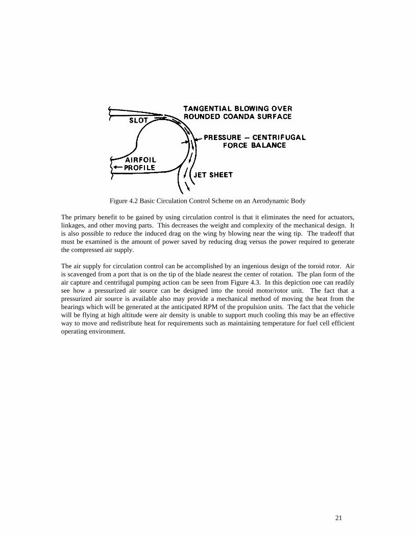
4.3 Circulation ControlThe previous discussion on flight controls stated that the initial plan for generating control power incruise is to use deflecting control surfaces. However, it is known that deflecting the control surfaces willincrease it drag on the aircraft and, thus, increase the power requirement. Also, since it may not befeasible to install solar panels on these surfaces, the solar collecting area is reduced. An alternativemethod for affecting airflow without control surface deflection is circulation control (blowing).Circulation control involves the ejection of a thin jet of air to directly affect the airflow about anaerodynamic surface (Fig. 4.2). The controlling jet of air is supplied by a compressed air source. The jetsheet controls the pressure distribution over the aerodynamic surface and is thus a very powerful methodof force generation. The blown sheet remains attached to the curved trailing edge by a balance between thenegative pressure differential across the jet and the centrifugal force acting on the curving jet. Theresulting flow entrained into the curving jet sheet initially acts as a boundary-layer control (BLC) at verylow momentum (blowing) coefficients to prevent separation. At slightly higher blowing, the jet adheres tothe round trailing edge, moving the airfoil's stagnation point and streamline well onto the lower surfaceand acting as a pneumatic circulation control. This greatly augments the airfoil lift well beyond that ofmechanical conventional high-lift flap systems, and into the region of Supercirculation with liftcoefficients up to 6.5. More importantly, force augmentations on the order of 80 times the blowingmomentum input have been observed in tests on 2-D airfoils (i.e. a return of 8000% on investment ofuseful work).
21
Figure 4.2 Basic Circulation Control Scheme on an Aerodynamic Body
The primary benefit to be gained by using circulation control is that it eliminates the need for actuators,linkages, and other moving parts. This decreases the weight and complexity of the mechanical design. Itis also possible to reduce the induced drag on the wing by blowing near the wing tip. The tradeoff thatmust be examined is the amount of power saved by reducing drag versus the power required to generatethe compressed air supply.
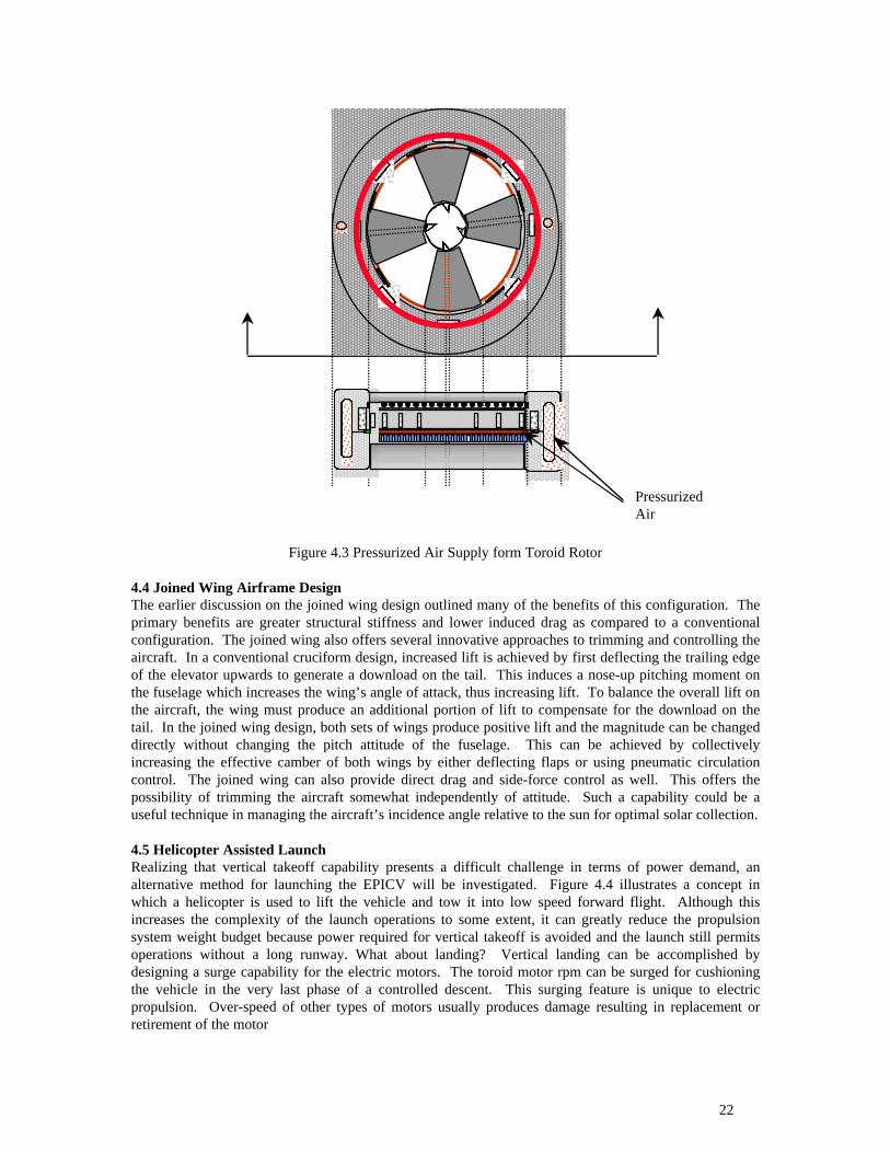
The air supply for circulation control can be accomplished by an ingenious design of the toroid rotor. Airis scavenged from a port that is on the tip of the blade nearest the center of rotation. The plan form of theair capture and centrifugal pumping action can be seen from Figure 4.3. In this depiction one can readilysee how a pressurized air source can be designed into the toroid motor/rotor unit. The fact that apressurized air source is available also may provide a mechanical method of moving the heat from thebearings which will be generated at the anticipated RPM of the propulsion units. The fact that the vehiclewill be flying at high altitude were air density is unable to support much cooling this may be an effectiveway to move and redistribute heat for requirements such as maintaining temperature for fuel cell efficientoperating environment.
22
Figure 4.3 Pressurized Air Supply form Toroid Rotor
4.4 Joined Wing Airframe DesignThe earlier discussion on the joined wing design outlined many of the benefits of this configuration. Theprimary benefits are greater structural stiffness and lower induced drag as compared to a conventionalconfiguration. The joined wing also offers several innovative approaches to trimming and controlling theaircraft. In a conventional cruciform design, increased lift is achieved by first deflecting the trailing edgeof the elevator upwards to generate a download on the tail. This induces a nose-up pitching moment onthe fuselage which increases the wing’s angle of attack, thus increasing lift. To balance the overall lift onthe aircraft, the wing must produce an additional portion of lift to compensate for the download on thetail. In the joined wing design, both sets of wings produce positive lift and the magnitude can be changeddirectly without changing the pitch attitude of the fuselage. This can be achieved by collectivelyincreasing the effective camber of both wings by either deflecting flaps or using pneumatic circulationcontrol. The joined wing can also provide direct drag and side-force control as well. This offers thepossibility of trimming the aircraft somewhat independently of attitude. Such a capability could be auseful technique in managing the aircraft’s incidence angle relative to the sun for optimal solar collection.
4.5 Helicopter Assisted LaunchRealizing that vertical takeoff capability presents a difficult challenge in terms of power demand, analternative method for launching the EPICV will be investigated. Figure 4.4 illustrates a concept inwhich a helicopter is used to lift the vehicle and tow it into low speed forward flight. Although thisincreases the complexity of the launch operations to some extent, it can greatly reduce the propulsionsystem weight budget because power required for vertical takeoff is avoided and the launch still permitsoperations without a long runway. What about landing? Vertical landing can be accomplished bydesigning a surge capability for the electric motors. The toroid motor rpm can be surged for cushioningthe vehicle in the very last phase of a controlled descent. This surging feature is unique to electricpropulsion. Over-speed of other types of motors usually produces damage resulting in replacement orretirement of the motor
PressurizedAir

23
Figure 4.4 Helicopter Assisted Launch
4.6 Wireless Power Transmission (WPT)Reference 5 provides an extensive survey of space borne power station theoretical discussion andexhaustive historical perspective on technical demonstrations of “beamed power’ from the ground. A verypersuasive argument is presented that pivots on the ever-increasing demand for power to support theearth’s ever-increasing population. The technological information presented shows clearly that WPT isthe key technology. We have utilized this technology for 40 years in the form of microwave ovens. Evenstandards have been developed that govern it’s safe use. In 1975, NASA demonstrated a 30KW beamcould be transmitted a distance of 1 mile at an efficiency of 82%. WPT was proven to be feasible.
For EPICV application of beamed power this research effort has focused on reversing the path that hasbeen the focus of all previous efforts. The paradigm that has been studied, demonstrated and discussed isa concept based upon ground receivers that are large “antennas” that receive the microwave energy andtransform it into electricity. The proposed approach for EPICV is to make the aircraft the target of theenergy beam as depicted in Figure 4.5 Spaced Based Power Supply. Surprisingly Reference 5 reportedon an experiment whereby a helicopter was powered in flight by a microwave beam. The microwavebeam was from a ground transmitter. What is being proposed as a result of this research is: beam energyfrom outerspace into the upper region of the atmosphere, directly on to the EPICV receiving antenna.
It is very exciting to also realize that laser energy has been considered for strategic missile defense. Theprocess of what a space borne missile defense system does and the functional requirement for pointing abeam of energy at a cooperative target for aircraft flight sustainment show tantalizing similarities. In theliterature [Ref 5] it is reported that a laser beam traveling through space may do so with very highefficiency—99%. Given that the EPICV would be at an altitude of 70K feet, atmospheric attenuation(loss) would not be as bad as for a beam originating from the ground.
The transmission and reception issues of beamed energy are complex. Admittedly much of the previouswork was focused upon up-and-down links for a notional aircraft. However, one experiment in the 1980’sdid prove the feasibility of sustaining flight for a drone with beamed microwave energy. This wasperformed on Canada in 1987. The drone reached altitude under battery power and when locked on to thebeam, it turned off its battery and was sustained via the microwave link. See Ref 5 for further details.

24
Pointing and controlling laser beams has received significant investigation under the aegis of StrategicMissile Defense research. Concentrated and dispersed beams generated by continuous wave electricdischarge lasers with recirculating gas have been studied. Gas circulation facilitates removal of excessheat, minimizes power consumption during long periods of operation. Carbon dioxide and carbonmonoxide electric discharge lasers have reached advanced development. Other laser concepts includingfree electron lasers, diode laser arrays and solar pumped lasers are under development. Power may beapplied to these lasers by photovoltaics or through direct excitation from solar flux. Photovoltaic cellssensitive to high frequency could be used to convert laser beam energy to d. c. electric output. Potentialfor interference from laser beamed energy is not an issue as with microwave. However, the chemicalreaction of thin atmosphere and possible plasma effects must be studied.
Based upon public information about the functional characteristics available on strategic ballistic missiledefense, it is possible that the power system for the missile defense system could serve two purposes—adual use technology application as it were. A strictly hypothetical concept is suggested by Figure 4.4.The space borne power stations that would necessarily support laser beam firing at a potential target couldpotential fire a laser beam of specific energy content at an EPICV system at it’s operational altitude of 70thousand feet. The algorithms for tracking the target and pointing the beam will have necessarily beenformulated from the early research on weapons operational concept. Further research is necessary to fullydevelop the potential role that could bridge this very important gap for sustainment energy for highaltitude UAVs.
One further dimension to the concept of beaming energy from space borne power stations should bedescribed. That concept is collaborative effort with between NASA and Department of Defense. Since themissile defense system will proceed under separate DOD funding, a collaborative effort should be initiatedbetween NASA and DOD to investigate the possible dual use of wireless power transmission (WPT)technology. From the NASA perspective the notional idea of charging industry a “fee for use” of powershould be investigated further. The basic idea of a privately owned UAV using energy captured andbeamed by space borne power stations which also have a defense mission is not as far fetched as it maysound. NASA may even consider selling “power-by-the-hour” as a way of recouping some of thedevelopmental costs.
Once again, these ideas are preliminary but they have potential merit at this point in the quest for a newparadigm for the application as described. Further study and investigation will be necessary to fully
Figure 04.5 Spaced Based Power Supply

25
explore the issues related to a future program for the commercial use of UAVs on such a grand scale. Thetechnology components are fragmented and no analytical tools exist that couple the interdependencies sothat alternative approaches can be evaluated for the technical and economic merit.
SECTION 5CONCLUSIONS AND FURTHER STUDY RECOMMENDATION
There are high altitude UAV designs that have flown and shown the technical viability of the concept. Itis not clear that designs based upon high aspect ratio wingspan are the optimum blend of propulsionefficiency and airframe design. The results of this research shows that there are technical alternatives thathold forth benefits which will entice the interest of industry and stimulate consideration in the privatesector of a whole new approach to wireless communication capacity expansion. This research has shownthat there is development activity in the area of fuel cells and electrolyzer systems that will be able toprovide power densities needed for continuous (24 hr.) operation.
The investigations conducted to this point have formed the conceptual definition for an autonomous, highaltitude air vehicle with a solar powered regenerative power system for telecommunications relay. Next, amore in-depth study must be performed to evaluate the feasibility of the concept and lay out thepreliminary design. This will involve a thorough examination of the current technology levels in areassuch as solar cells, fuel cells, electrolyzers, batteries, chargers, and electric motors. Also, a number oftrade studies must be conducted to select those technologies that offer the highest overall efficiency andwill be available within the required timeframe. The tasks for the feasibility and preliminary designstudies are outline below.
5.1 Further StudyDuring the course of the current investigation numerous trade papers, press releases, and advertisingliterature in various technology areas were reviewed. The published data paints fairly promising portraitsof each of the technologies being offered. However, to truly establish the level of capability in areas suchas solar cell efficiency or fuel cell efficiency, a more in-depth evaluation must be made. This will requireforming cooperative arrangements with the technology developers to gain access to information regardingtheir shortcomings rather than just their well-publicized successes. Such “inside” information is necessaryto gauge the feasibility of using their technology for this unique application.
5.1.1 Solar Cells• Consult and visit independent experts at the National Renewable Energy Laboratory, Golden, CO
and Sandia National Laboratories, Albuquerque, NM.• Conduct cooperative investigations with various commercial solar cell providers to establish
current and projected capabilities.• Establish database on solar cell characteristics for use in tradeoff studies.
5.1.2 Fuel Cells and Electrolyzers• Consult and visit independent experts at the NASA Glenn Research Center, Lewis Field, OH and
Argonne National Laboratory, Chicago, IL.• Conduct cooperative investigations with various commercial fuel cell and electrolyzer providers
to establish current and projected capabilities for EPICV application.• Establish database on fuel cell and electrolyzer characteristics for use in tradeoff studies.
5.1.3 Batteries and Chargers• Consult and visit independent experts at Argonne National Laboratory, Chicago, Il.• Conduct cooperative investigations with various commercial battery and charger providers to
establish current and projected capabilities for EPICV application.• Establish database on battery and charger characteristics for use in tradeoff studies.
26
5.1.4 Electric Motors• Consult and visit independent experts at Aerovironment and Aurora.• Conduct cooperative investigations with Fisher Electronics to establish current and projected
capabilities for toroid motor/rotor units.• Establish database on electric motor characteristics for use in tradeoff studies.
5.1.5 Telecommunications SatellitesEstablish range of expected weight and power requirements for telecommunications payloads serving alarge metropolitan area through cooperative investigations with leading satellite manufacturers such asHughes, Loral, etc.
5.1.6 Telecommunications/Wireless Throughput RequirementsEstimate projected telecommunications throughput requirements within the next 10 – 20 years forcandidate metropolitan areas through consultation with telecommunications service providers such asPanamsat, Bell South etc.
5.2 Tradeoff StudiesTradeoff studies will be conducted using the information gathered through consultation and cooperativeinvestigations. The process will involve determining what simulation models of the various aspects of theEPICV system should be developed to minimize risk and conduct those trade studies.
5.2.1 Aircraft ModelTake NASA’s solar powered HALE UAV modeling program and modify it for EPICV (i.e., include effectsof ducted rotors, joined wing, etc.)
5.2.2 Power System ModelIn conjunction with GTRI’s Systems Development Laboratory create power system model of solar cells,fuel cells, electrolyzers, chargers, batteries, electric motors, signal conditioning, flight control computerand actuators, and payload power requirements. In addition to modeling efficiencies, include effects ofwaste heat and its management.
5.3 Preliminary DesignUse aircraft and power system models to conduct preliminary design of complete aircraft system.
5.4 Collaboration to obtain Spaceborne Power
Once the phase II preliminary design effort is successful, the next step is to seek collaboration onreceiving beamed power from power stations developed by DOD or commercial sources. Most probably thpower stations will be developed for the Ballistic Missile Defense Program. However there has been avery active voice in calling for movement by NASA to proceed with power station development (see ref.25). There are other exploration initiatives that will create demand for power, lunar exploration andcolonization as well as deep space travel and colonization. Once the EPICV system has beencharacterized in phase II, research efforts should proceed into the space borne power scenariodevelopment.
27
SECTION 6REFERENCES
1. Kitt C. Reinhard, Thomas R. Lays, Jack W. Gels, “Solar Powered Unmanned Aerial Vehicles” theAero Propulsion and Power Directorate, Wright Laboratory, and Anthony Colozza, AerospaceTechnology Department, NYMA Corporation, was presented at Intersociety Energy ConversionEngineering Conference in Washington D. C., in August 1996.
2. Raymond Prouty, Helicopter Performance; Stability, and Control, Duxburry Press, Breton Publishers,1986.
3. Dr. Julian Wolkovitch, “Principles of the Joined Wing”, Engel Engineering Company Report No. 80-1, Dec. 3, 1980, Rancho Palos Verdes, California.
4. Green, M.A., Emery, K., et. Al., Solar Cell Efficiency Tables (Version 12), Progress in PhotovoltaicsResearch and Applications, 6, 265-270 (1998)
5. Peter E. Glazer, Frank Davidson, Katinka Csigi, Solar Power Satellites “A Space Energy System forEarth”, John Wiley & Sons, Praxis Publishing, Eastergate, Chichester West Succex, England.
6. Scheiman, D.K., Brinker, D.J., Bents, D.J., Colozza, A.J., Design of a GaAs/Ge Solar Array forUnmanned Aerial Vehicles, NASA TM – 106870, NASA Lewis, March 1995
7. Suzuki, A., High-efficiency silicon space solar cells, Solar Energy Materials and Solar Cells, 50, 289-303 (1998)
8. Flood, D.J., Clark, E.B., Introduction to a Selection of Papers from SPRAT XV, ), Progress inPhotovoltaics Research and Applications, 5, 381-384 (1997)
9. Yeh, Y.C.M., et al, Advances in Production of Cascade Solar Cells for Space, 26th PVSC 827-830(1997) Techstar/ASD
10. Rand, J.A., et al, Large-Area Silicon-Film Manufacturing Under the PVMaT Program, 26thPVSC1169-1172 (1997) AstroPower
11. Wilkinson,, V.A., Goodbody, C., Measurement of Multijunction Cells under Close-Match Conditions,26th PVSC 947-950 (1997) Space Power Laboratory
12. Colozza, A.J., Effect of Power System Technology and Mission Requirements on High Altitude LongEndurance Aircraft, NASA CR 194455, February 1994 Sverdrup Technology Incorporated
13. Nowlan, M.J., Maglitta, J.C., Darkazalli, G., Lamp, T., Ultralight Photovoltaic Modules forUnmanned Aerial Vehicles, 26th PVSC 1149-1152 (1997) Spire Corporation
14. Colozza, A.J., Effect of Date and Location on Maximum Achievable Altitude for a Solar PoweredAircraft. NASA CR-202326, November 1996, NYMA Inc. NASA Lewis
15. Bailey, S.G., Flood, D.J., Space Photovoltaics, ), Progress in Photovoltaics Research andApplications, 6, 1-14 (1998)
16. Wojtczuk, S., Reinhardt, K., High-Power Density (1040 W/kg) GaAs Cells for Ultralight Aircraft,25th PVSC 49-52 (1996) Spire Corporation

28
17. Lamp, T., Reinhardt, K.C., Colozza, A.J., Photovoltaic Power for Long Endurance Unmanned AerialVehicles, LERC web page
18. Dimmler, B., Schock, H.W., Scalability and Pilot Operation in Solar Cells of CuInSe2 and theirAlloys, Photovoltaics Research and Applications, 6, 193-199 (1998)
19. Shi, Z., Green, M.A., Survey of Material Options and Issues for Thin Film Silicon Solar Cells,Progress in Photovoltaics Research and Applications, 6, 247-257 (1998)
20. Zheng, G.F., Wenham, S.R., Green, M.A., 17.6% Efficient Multilayer Thin-film Silicon Solar CellsDeposited on Heavily Doped Silicon Substrates, Progress in Photovoltaics Research and Applications,4, 369-373 (1996)
21. Green, M.A., Jordan, D., Technology and Economics of Three Advanced Silicon Solar Cells,Progress in Photovoltaics Research and Applications, 6, 169-180 (1998)
22. Green, M.A., Wenham, S.R., Novel paralles multijunction solar cell, Applied Physics Letters, 65 (23)2907-2909 (December 5, 1994)
WIRELESS POWER TRANSMISSION
23. Landis, G.A., Photovoltaic Receivers for Laser Beamed Power in Space, NASA Contract Report189075, December 1991
24. Hawkins, J., WISPER, Wireless Space Power Experiment, NTIS Accession Number N95-12661/1/XAB, Also Titled “Powersat: A Technology Demonstration of a Solar Power Satellite” bySigler, et al.
25. **NERAC, Inc., Tolland, CT, NTIS, Springfield, VA, Microwave Generation and Transmission(Latest Citations from the INSPEC Database), NTIS Accession Number PB97-861884/XAB, July1997.
26. **Proceedings of the 1st Annual Wireless Power Transmission Conference, 23-25 February 1993, SanAntonio TX
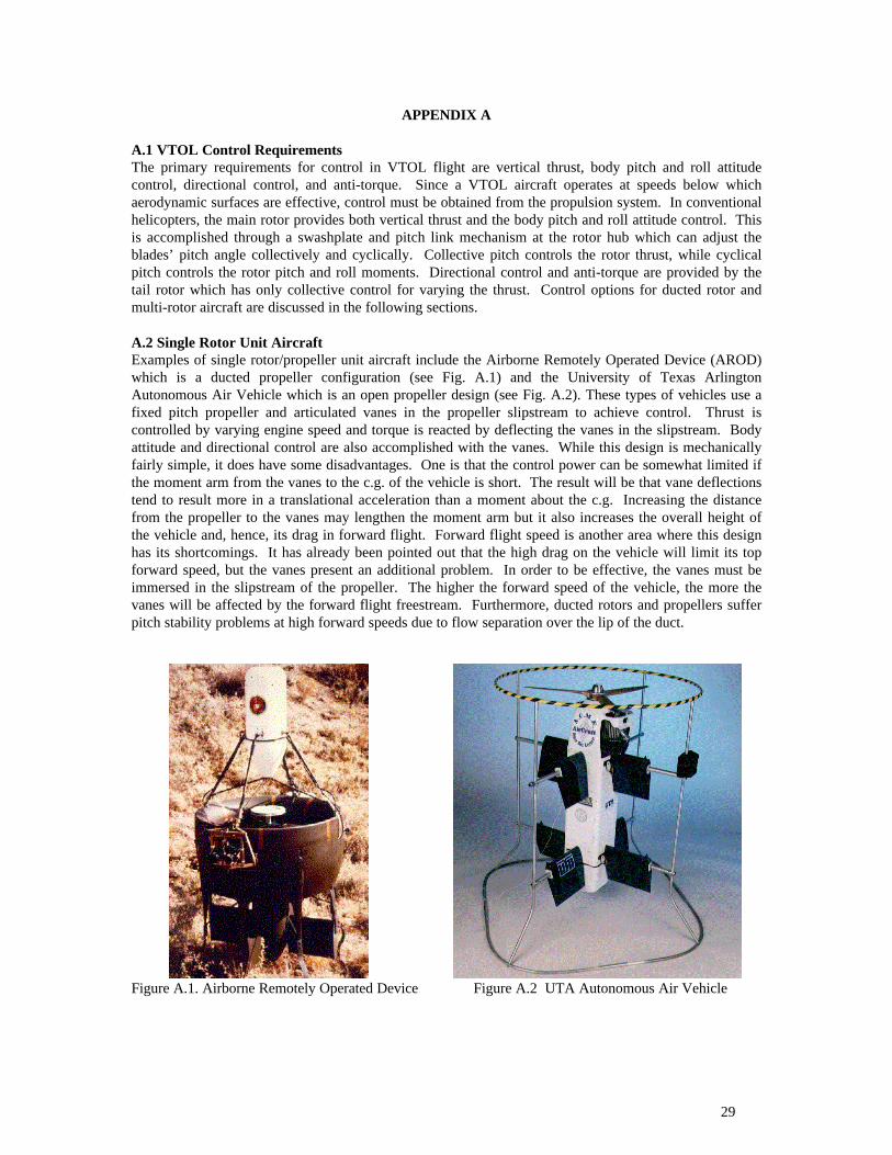
29
APPENDIX A
A.1 VTOL Control RequirementsThe primary requirements for control in VTOL flight are vertical thrust, body pitch and roll attitudecontrol, directional control, and anti-torque. Since a VTOL aircraft operates at speeds below whichaerodynamic surfaces are effective, control must be obtained from the propulsion system. In conventionalhelicopters, the main rotor provides both vertical thrust and the body pitch and roll attitude control. Thisis accomplished through a swashplate and pitch link mechanism at the rotor hub which can adjust theblades’ pitch angle collectively and cyclically. Collective pitch controls the rotor thrust, while cyclicalpitch controls the rotor pitch and roll moments. Directional control and anti-torque are provided by thetail rotor which has only collective control for varying the thrust. Control options for ducted rotor andmulti-rotor aircraft are discussed in the following sections.
A.2 Single Rotor Unit AircraftExamples of single rotor/propeller unit aircraft include the Airborne Remotely Operated Device (AROD)which is a ducted propeller configuration (see Fig. A.1) and the University of Texas ArlingtonAutonomous Air Vehicle which is an open propeller design (see Fig. A.2). These types of vehicles use afixed pitch propeller and articulated vanes in the propeller slipstream to achieve control. Thrust iscontrolled by varying engine speed and torque is reacted by deflecting the vanes in the slipstream. Bodyattitude and directional control are also accomplished with the vanes. While this design is mechanicallyfairly simple, it does have some disadvantages. One is that the control power can be somewhat limited ifthe moment arm from the vanes to the c.g. of the vehicle is short. The result will be that vane deflectionstend to result more in a translational acceleration than a moment about the c.g. Increasing the distancefrom the propeller to the vanes may lengthen the moment arm but it also increases the overall height ofthe vehicle and, hence, its drag in forward flight. Forward flight speed is another area where this designhas its shortcomings. It has already been pointed out that the high drag on the vehicle will limit its topforward speed, but the vanes present an additional problem. In order to be effective, the vanes must beimmersed in the slipstream of the propeller. The higher the forward speed of the vehicle, the more thevanes will be affected by the forward flight freestream. Furthermore, ducted rotors and propellers sufferpitch stability problems at high forward speeds due to flow separation over the lip of the duct.
Figure A.1. Airborne Remotely Operated Device Figure A.2 UTA Autonomous Air Vehicle

30
Figure A.3 Moller Aerobot
The Moller Aerobot (Fig. A.3) and the Sikorsky Cypher (Fig. 2.6) both employ a single duct housing twocounter-rotating rotors. In these vehicles, the counter-rotating rotors eliminate the need for a separateanti-torque device. The Aerobot uses fixed-pitch propellers and thrust is controlled by motor speed.Directional control is achieved through differential thrust (and, hence, torque) on the two propellers.Attitude control is achieved through vanes in the propeller slipstream. The Sikorsky Cypher uses fullyarticulated rotors with collective and cyclic control such as on a conventional helicopter. Directionalcontrol is obtained through differential thrust (torque) and attitude control is achieved through the cyclicpitch inputs to the rotor system. The collective and cyclic control mechanism on the Cypher does makethe hub more complex, but it gives the vehicle significantly more control power than would be possiblewith vanes in the slipstream. It should be noted that because they are ducted systems, these vehicles havethe same high forward speed problems as those previously mentioned.
A.3 Multi-Rotor Unit AircraftOne example of a dual rotor unit aircraft is the Piasecki PA-59 called the “Airgeep” (see Fig. A.4)developed during the late 1950’s and early 1960’s. The vehicle consisted of two ducted rotors arranged intandem and turning in opposite directions to balance torque. Thrust was controlled by collective pitch onboth rotors rather than by engine speed variation with fixed pitch propellers. Although a collective pitchmechanism makes the hub system more complex, this technique is more responsive that engine speedvariation ,particularly for piston and turbine engines. In fact, turbine engines must typically be operatedwithin a fairly narrow speed range which, more or less, dictates the use of a blade collective pitchmechanism and engine speed governor.
The body pitch attitude of the Airgeep was controlled by differential collective on the rotors. The bodylateral control was achieved with lateral cyclic on the rotors for moment generation and by longitudinallydisposed vanes in the slipstream for side force generation. Again, the hub is made more complex by the
use of a lateral cyclic mechanism; however, as it was noted earlier, slipstream vanes do not provideadequate roll moment generation because of their short moment arm from the aircraft c.g. Differentialdeflection of the vanes provided directional control. A later version of the Airgeep (shown in Fig. A.4)had a canted fuselage which placed the rear duct at a smaller inflow turn angle than the forward duct in
forward flight. This was done to reduce the momentum drag caused by the sharp turn of the inflow
through the Figure A.4 Piasecki PA-59H, the “Airgeep”

31
horizontal rotors. Top speed for the Airgeep was approximately 55 knots.Another dual ducted rotor configuration was the Doak VZ-4 shown in Fig. 2.8. The VZ-4 had laterallydisposed, ducted rotors that were tilted vertically for hovering flight then rotated to a horizontal attitudefor forward flight. The rotors turned in opposite directions to balance torque. In vertical flight mode,thrust was controlled by collective blade pitch on the two rotors and lateral control was achieved bydifferential thrust. The body pitch attitude was controlled by reaction jets at the tail of the aircraft. Thissimplified the design of the rotor hub (in that no blade cyclic control mechanism was used) by shifting thecomplexity to the jet reaction control system. Directional control was by differential deflection of vanes inthe rotor slipstream. Because the ducted rotor units on the VZ-4 rotated to a horizontal position, it couldachieve high speed flight without suffering the problems of vertically oriented ducted rotors in forwardflight.
Another dual rotor system VTOL configuration is the tiltrotor. Examples of this type include the XV-15(see Fig. 2.9) and the V-22. Like the VZ-4, these aircraft use tilting rotors to achieve both hover and highspeed flight. Their rotor systems employ conventional helicopter rotor controls, i.e., collective and cyclicblade pitch mechanisms. Thrust is controlled by collective blade pitch on both rotors, while roll iscontrolled by differential collective (thrust) on the rotors. The aircraft pitch attitude is controlled bylongitudinal cyclic and yaw is controlled by differential longitudinal cyclic on the rotors. Lateral cyclic isavailable to translate the aircraft laterally with very little body roll. While the use of conventionalhelicopter rotor controls makes the hub system quite complex, it provides the aircraft with exceptionalcontrol power and makes it highly maneuverable.
One type of a three rotor system aircraft is the tiltwing, of which the CL-84 is an example (see Fig. A.5).The configuration consists of two large lifting propellers rigidly attached to a rotating wing and a smallpropeller or ducted fan at the rear of the vehicle. The lifting propellers have collective control only andare used together to control thrust and differentially to control roll in VTOL mode. The small propeller orducted fan in the tail is used for pitch attitude control and does not contribute significantly to verticalthrust on the vehicle. This pitch fan has collective control only for varying thrust, which, in turn, changesthe pitching moment about the c.g. of the aircraft. This arrangement simplifies the design of the mainrotor hub by eliminating the cyclic pitch mechanism and shifting the complexity to the tail pitch fan.Directional control is obtained from the differential deflection of flaps in the slipstream. Since torque onthe small pitch control rotor is low, the overall torque is balanced by having the two main lifting rotorsturn in opposite directions.
Another tri-rotor system concept is the GTRI Traffic Surveillance Drone (Fig. A.6). The design for thisvehicle consists of a single, large, horizontally mounted lifting rotor and two smaller forward-facingducted propellers (called propulsors). The lifting rotor employs a swashplate for conventional helicoptercollective and cyclic control. This provides for thrust control as well as the body pitch and roll control.The propulsors have collective control for varying thrust. Differential thrust on the propulsors is used foranti-torque and for directional control. Collective thrust on the propulsors is used for forward flightpropulsion. A tail boom with horizontal and vertical stabilizers is also included because of concernsregarding the pitch stability of ducted rotor systems in forward flight.
Figure A.5 Canadair CL-84 Tiltwing Figure A.6 GTRI Traffic Surveillance Drone
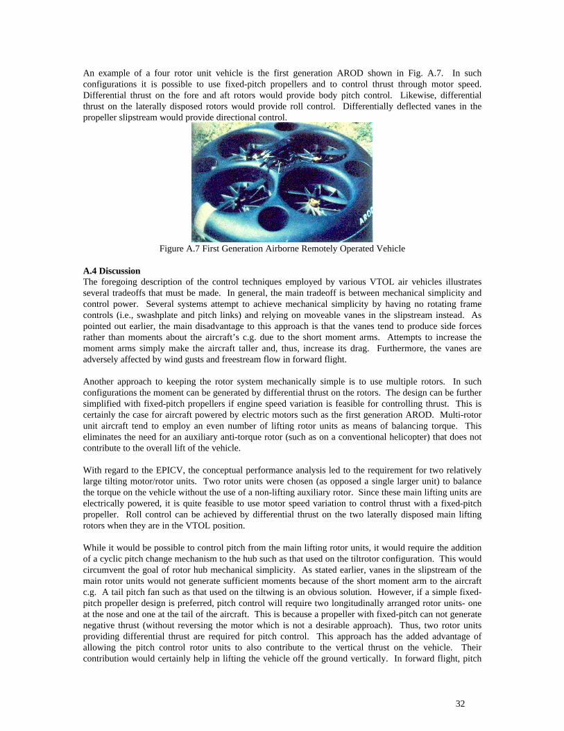
32
An example of a four rotor unit vehicle is the first generation AROD shown in Fig. A.7. In suchconfigurations it is possible to use fixed-pitch propellers and to control thrust through motor speed.Differential thrust on the fore and aft rotors would provide body pitch control. Likewise, differentialthrust on the laterally disposed rotors would provide roll control. Differentially deflected vanes in thepropeller slipstream would provide directional control.
Figure A.7 First Generation Airborne Remotely Operated Vehicle
A.4 DiscussionThe foregoing description of the control techniques employed by various VTOL air vehicles illustratesseveral tradeoffs that must be made. In general, the main tradeoff is between mechanical simplicity andcontrol power. Several systems attempt to achieve mechanical simplicity by having no rotating framecontrols (i.e., swashplate and pitch links) and relying on moveable vanes in the slipstream instead. Aspointed out earlier, the main disadvantage to this approach is that the vanes tend to produce side forcesrather than moments about the aircraft’s c.g. due to the short moment arms. Attempts to increase themoment arms simply make the aircraft taller and, thus, increase its drag. Furthermore, the vanes areadversely affected by wind gusts and freestream flow in forward flight.
Another approach to keeping the rotor system mechanically simple is to use multiple rotors. In suchconfigurations the moment can be generated by differential thrust on the rotors. The design can be furthersimplified with fixed-pitch propellers if engine speed variation is feasible for controlling thrust. This iscertainly the case for aircraft powered by electric motors such as the first generation AROD. Multi-rotorunit aircraft tend to employ an even number of lifting rotor units as means of balancing torque. Thiseliminates the need for an auxiliary anti-torque rotor (such as on a conventional helicopter) that does notcontribute to the overall lift of the vehicle.
With regard to the EPICV, the conceptual performance analysis led to the requirement for two relativelylarge tilting motor/rotor units. Two rotor units were chosen (as opposed a single larger unit) to balancethe torque on the vehicle without the use of a non-lifting auxiliary rotor. Since these main lifting units areelectrically powered, it is quite feasible to use motor speed variation to control thrust with a fixed-pitchpropeller. Roll control can be achieved by differential thrust on the two laterally disposed main liftingrotors when they are in the VTOL position.
While it would be possible to control pitch from the main lifting rotor units, it would require the additionof a cyclic pitch change mechanism to the hub such as that used on the tiltrotor configuration. This wouldcircumvent the goal of rotor hub mechanical simplicity. As stated earlier, vanes in the slipstream of themain rotor units would not generate sufficient moments because of the short moment arm to the aircraftc.g. A tail pitch fan such as that used on the tiltwing is an obvious solution. However, if a simple fixed-pitch propeller design is preferred, pitch control will require two longitudinally arranged rotor units- oneat the nose and one at the tail of the aircraft. This is because a propeller with fixed-pitch can not generatenegative thrust (without reversing the motor which is not a desirable approach). Thus, two rotor unitsproviding differential thrust are required for pitch control. This approach has the added advantage ofallowing the pitch control rotor units to also contribute to the vertical thrust on the vehicle. Theircontribution would certainly help in lifting the vehicle off the ground vertically. In forward flight, pitch

33
control can be achieved with a conventional tail mounted elevator and the fore and aft pitch fans can beshut down. This would eliminate the potential pitch instability associated with ducted rotors in forwardflight. The main lifting rotors would not be susceptible to this pitch instability because they are tiltedforward with increasing airspeed and remain in primarily axial flow.Directional control on the UAV can be accomplished with vanes in the slipstream of the pitch controlrotor units. In this axis (longitudinal), the vanes would have a fairly long moment arm to the aircraft c.g.which should be near the center of the body. Furthermore, the vanes would be oriented longitudinallywhich would minimize their impact on aircraft drag. In forward flight, once the aircraft’s speed is highenough to transfer control to the rudders, the vanes could be folded flat to close off the pitch rotor ductsand further decrease the aircraft drag. Some studies will have to be conducted to determine if thisarrangement can provide enough directional control power particularly when the long joined-wings areattached. It is possible that vanes may have to be placed laterally in the main lifting rotor’s slipstream togenerate the required directional control power. The effect of these vanes on aircraft drag should beminimal since the vanes will rotate with the rotor unit and remain aligned with the air flow.
A.5 Conceptual Control Law DesignGiven the range in flight environment (from low altitude VTOL to high altitude cruise) and the
changes in configuration, the EPICV will require a fairly sophisticated automatic control system. Thiscontrol system will have to handle the transition from control with thrusters in VTOL mode to controlwith aerodynamic surfaces in forward flight mode. Also, ease of operation will be essential, requiring theautomation of some functions such as MRU tilt, attitude stabilization, and, perhaps, waypoint following.
The control law design will follow the classical single loop closure approach with multiple levelsof feedback loops. The methodology is well understood and a significant number of analysis tools arereadily available. While the application of more modern control law design techniques such as neuralnetworks and fuzzy logic may be intriguing (especially from an academic viewpoint), the classicalapproach tends to have lower risk when designing for new vehicle types. Since the dynamics of a newaircraft type are not usually fully known, the classical approach allows the designer to focus on the effectsof each feedback loop on the aircraft’s response. Understanding the effects of the feedback gain and beingable to adjust it for individual loops provides much need flexibility in dealing with the disparity betweenthe linear models used for control law design and the nonlinear dynamics of the actual vehicle. This isone of the reasons the classical approach was used for designing the fly-by-wire control laws of the V-22tiltrotor.
The control laws envisioned for the EPICV consist of (from innermost to outermost loops): bodyrate feedback for stabilization, attitude feedback for attitude hold and turn coordination, velocity feedbackfor airspeed hold, and position feedback for hover hold and waypoint following. The followingparagraphs describe the planned control law format for each aircraft axis. These control laws weredeveloped as part of an earlier simulation effort involving the CH-53 helicopter (Ref. A-9315). Thecontrol laws were used in conjunction with a trajectory command generator to “fly” a high fidelity,nonlinear dynamic model of the CH-53 through a series of prescribed maneuvers. The goal of the effortwas to determine the rotor system loads during maneuvers.
A.5.1 Longitudinal (Pitch) AxisThe longitudinal axis baseline control laws are designed for rate command/attitude hold using a
proportional plus integral body rate inner loop (see Fig. A.8). The body pitch rate is fed back through afirst order lag to minimize the control system's response to high frequency oscillations in the range of therotor dynamics and wing structural dynamics. The time constant for the filter will be set to roll off therate signal above 10 rad/sec to eliminate feedback at frequencies higher than the handling qualitiesfrequency domain. If the frequencies of the wing structural modes are lower than 10 rad/sec, a notch filtermay be required to prevent interaction between the control system and the wing structural response.
The aircraft's pitch attitude is held whenever zero body rate is commanded and the actual bodyrate falls within a "capture" window. The attitude hold is released when a nonzero body rate is

34
commanded. Attitude error signals are fed through a first order lag to prevent the control system forexciting higher frequency modes. This permits good low frequency tracking on attitude while minimizingthe destabilizing effect that attitude feedback can have.
Kq
θ
Kθ
KqI
q
θc
qc
δs
s
1τ1s+1
τ2s+1--
+++
++
HOLD θ1
2SW
If q c=0 and q< ε, SW=1 If q c=0, SW=2
Figure A.8 - Pitch Axis Baseline Control System
An additional outer loop closure is made to the pitch axis to feed back longitudinal speed for avelocity command system. Fig. A.9 shows the addition of the outer velocity command loop to the RCAHstructure. Velocity feedback is inertial based from a GPS sensor rather than airspeed based. Usinginertial based velocity allows the velocity command system to operate in the low speed regime where anairspeed sensor becomes inaccurate. Note that when the velocity command loop is engaged, the attitudefeedback loop is opened.
θ
Kθθc
τ2s+1-
+
HOLD θ1
2SW
-
+
Vx
Vxc
+
Figure A.9 - Longitudinal Velocity Command Loop
Other outer features will be added to the baseline longitudinal controller to provide:
1. Position Hold - An inertial position feedback loop to maintain position as part of a hoverhold function
2. MRU Tilt/Pitch Decoupling - A feedforward command proportional to the MRU tilt rate toreduce the pitching moment due to inertial coupling as the MRUs are rotated
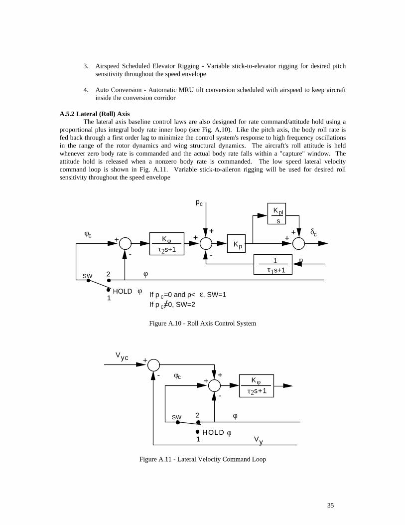
35
3. Airspeed Scheduled Elevator Rigging - Variable stick-to-elevator rigging for desired pitchsensitivity throughout the speed envelope
4. Auto Conversion - Automatic MRU tilt conversion scheduled with airspeed to keep aircraftinside the conversion corridor
A.5.2 Lateral (Roll) AxisThe lateral axis baseline control laws are also designed for rate command/attitude hold using a
proportional plus integral body rate inner loop (see Fig. A.10). Like the pitch axis, the body roll rate isfed back through a first order lag to minimize the control system's response to high frequency oscillationsin the range of the rotor dynamics and wing structural dynamics. The aircraft's roll attitude is heldwhenever zero body rate is commanded and the actual body rate falls within a "capture" window. Theattitude hold is released when a nonzero body rate is commanded. The low speed lateral velocitycommand loop is shown in Fig. A.11. Variable stick-to-aileron rigging will be used for desired rollsensitivity throughout the speed envelope
Kp
φ
Kφ
KpI
p
φc
pc
δc
s
1τ1s+1
τ2s+1--
+++
++
HOLD φ1
2SW
If p c=0 and p< ε, SW=1 If p c=0, SW=2
Figure A.10 - Roll Axis Control System
φ
Kφφc
τ2s+1-
+
HOLD φ1
2SW
-
+
Vy
Vyc
+
Figure A.11 - Lateral Velocity Command Loop

36
A.5.3 Directional (Yaw) AxisThe directional axis control is based on the same rate command, proportional plus integral
structure as the pitch and roll axes loops (see Fig. A.12). A turn coordinator is also provided thatautomatically applies yaw rate commands to minimize the lateral acceleration in a turn. The yaw ratecommand for turn coordination is derived using the equation for lateral acceleration:
a y = Ý v + ru − pw − g cos θ sin φ
where a y is the lateral acceleration, u , v , and w are the longitudinal, lateral, and vertical body
velocities, respectively, p and r are the roll and yaw rates, and θ and φ are the pitch and roll attitudes,
respectively. In a coordinated turn it is desired to have a y = 0 and Ý v = 0 and for a steady turn, p = 0 .
Solving for the turn coordination yaw rate yields
rTC =g
ucos θ sin φ
Sideslip is also fed back to coordinate the turn. Airspeed scheduled rudder rigging will be used fordesired yaw sensitivity throughout the speed envelope.
K r
ψ
Kψ
KrI
r
ψc
rc
δp
s
1τ1s+1
τ2s+1--
+++
++
HOLD ψ1
2SW
If r c=0 and r< ε and TC=OFF, SW=1 If r c=0 or TC=ON, SW=2
cos
sin Π
θ
φ
u
rTC+
+
+
+
KβI
s
Kββ
0
TCON
OFF 0OFF
ONTC
-
Figure A.12 - Yaw Axis Control System
A.5.4 Vertical (Thrust) AxisThe vertical axis employs rate command type system based on vertical rate feedback with altitude
hold (see Fig. A.13).

37
KhKh
KhI
h
hc
hc
δo
s
1τ1s+1
τ2s+1--
+++
++
H OLD h1
2SW
If hc=0 and h<ε, SW=1 If hc=0, SW=2
h
Figure A.13 - Vertical Axis Control System
A.6 Control Law DevelopmentControl laws will be developed for the EPICV in an iterative fashion as illustrated in Fig. A.14.
The initial set of control laws will be developed using a six degree of freedom simulation model based onanalytical equations. This simulation will use estimates of the vehicle’s mass, c.g., moments of inertia,aerodynamic properties, and control effectiveness to model the aircraft’s dynamic response. The modelwill be updated with more accurate representations with the results from bench tests, wind tunnel tests,and free-flight tests.
SimulationRevised Control Laws
Test Results
TestingInitial Control Laws
Figure A.14 - Control Law Development Process
Bench testing will include frequency domain tests to determine the bandwidth of the controlsystem. These tests will be conducted by applying a sinusoidal input of varying frequency to the controlsystem and measuring the response of the system. Using frequency domain system identificationtechniques, the control system model parameters can be determined including bandwidth, damping, andphase (time) delays. This type of testing is essential in order to design a control system that is not so slowas to be sluggish nor so fast that it excites structural modes or becomes unstable.
Wind tunnel testing will be required to determine the aerodynamic characteristics of the vehicle.Although these tests will be conducted under static conditions, crucial dynamic model data, such ascontrol sensitivity derivatives, can be obtained. These tests will also provide the necessary data for theaircraft’s performance model.
Frequency domain testing of the vehicle in free (or tethered) flight will be necessary to obtainvalues for the modeling parameters that are functions of the body rates and accelerations. These tests canbe conducted with an initial set of control laws under tightly controlled conditions. The results from thetest will be used to update the simulation model which will then be used to upgrade the control laws.Development will proceed in this fashion until up-and-away flight is achieved.