final report p
TRANSCRIPT
This publication is published by Meat & Livestock Australia Limited ABN 39 081 678 364 (MLA). Care is taken to ensure the accuracy of the information contained in this publication. However MLA cannot accept responsibility for the accuracy or completeness of the information or opinions contained in the publication. You should make your own enquiries before making decisions concerning your interests. Reproduction in whole or in part of this publication is prohibited without prior written consent of MLA.
Project code: A.ENV.0094 Prepared by: Neil McPhail & Darren
Rossington CSIRO
Date published: March 2010
PUBLISHED BY Meat & Livestock Australia Limited Locked Bag 991 NORTH SYDNEY NSW 2059
The use of abattoir waste heat for absorption refrigeration
final repport
Meat & Livestock Australia acknowledges the matching funds provided by the Australian Government and contributions from the Australian Meat Processor Corporation to support the research and development detailed in this publication.
Page 2 of 43
Abstract Under a carbon pollution reduction scheme (CPRS) or alternative system for reduction of greenhouse gases, Australian meat processors will be expected to pay for the discharge of carbon dioxide equivalent (CO2-e) emissions in addition to increased prices for electricity. Capture of the biogas from anaerobic effluent ponds for use as a fuel and greater utilisation of waste heat could reduce these costs. An economic evaluation of absorption refrigeration operating on biogas has been conducted.
A packaged lithium bromide/water absorption chiller is the most appropriate but as with other absorption refrigeration types is best suited to air conditioning applications. It could also be used to produce chilled water for carcase spray chilling. The input heat could be sourced from the waste heat from a biogas-powered engine generator or by direct firing.
The cogeneration system has high capital and maintenance costs resulting in long payback times. Direct firing of the absorption chiller is potentially more attractive but would still require a price on emissions in order to be viable. Utilising the biogas directly in an existing gas-fired boiler provides the best return on investment mainly due to the lower capital costs.
A.ENV.0094 - The use of abattoir waste heat for absorption refrigeration

Page 3 of 43
Executive Summary Under the Federal Government's proposed carbon pollution reduction scheme (CPRS), the larger Australian meat processing plants will have an obligation to purchase permits equivalent to their carbon dioxide equivalent (CO2-e) emissions. Depending on the price of these permits, processors will face additional annual charges of upwards of $250,000. These costs could be reduced by capturing the biogas from anaerobic ponds and utilising it as a fuel. Overall energy costs can be reduced by fully utilising waste heat sources around the processing plant.
Absorption refrigeration has lower operating costs than the traditional vapour-compression systems as it is able to utilise waste heat or can be direct fired. An absorption system could operate on the waste heat from a rendering plant or the exhaust heat from a cogeneration plant running on methane from biogas. Therefore the objectives of this project were to assess the economics of absorption refrigeration using waste heat from:
a. dry rendering;b. a cogeneration plant running on biogas from anaerobic ponds,
for larger beef plants that fall under the CPRS and medium-sized plants.
Abattoirs that incorporate dry rendering facilities condense the cooker vapours to control odour and to generate hot water that is stored in insulated tanks for use on the plant. Some plants report that an excess of hot water is produced resulting in hot water being wasted. A spreadsheet has been developed to allow ready calculation of the quantity of hot water produced from the waste heat exchanger and for this quantity to be compared with the expected hot water requirements of the plant.
In the case of plants with average hot water requirements and processing industry average-sized animals, there is unlikely to be an excess of hot water. However plants processing heavy cattle and having cut back their hot water requirements could produce more hot water than required, especially in summer when cooling water temperatures are higher.
Many Australian abattoirs use anaerobic ponds as the first stage in the secondary treatment of their wastewater. Biogas containing about 65% methane is a product of anaerobic digestion and unless captured will contribute to the plant’s carbon footprint. There is minimal data on the quantity of methane emitted by abattoir anaerobic ponds in Australia but it is likely to be within the range 0.15 to 0.3 m3/kg COD removed.
The methane produced can be used to power a gas engine which drives a generator to produce electricity and the exhaust heat used for absorption refrigeration. Depending on the electricity tariff, it is likely to be more economical to operate the cogeneration system for only 15 hours per day during the peak and shoulder period of the day and store the gas at other times.
Under these conditions, the system in a medium-sized abattoir (450 cattle/day) would produce 214 – 426 kW electricity and 299 – 596 kW refrigeration. In a large abattoir (1600 cattle/day), 758 to 1515 kW of electricity and 1062 to 2123 kW of refrigeration could be produced.
A number of possible sorption cooling technologies are available for converting waste heat into cooling for application in abattoirs. Each of these technologies has features that make them more or less suitable for the target application.
Water-lithium bromide solution absorption chillers are a mature cost-effective and efficient technology used extensively in building air conditioning applications. However, they are unable to achieve refrigeration temperatures below zero degrees Celsius. Ammonia-water absorption
A.ENV.0094 - The use of abattoir waste heat for absorption refrigeration

Page 4 of 43
refrigerators with ammonia as the refrigerant can achieve sub-zero temperatures. This technology is considered an attractive prospect for abattoir refrigeration applications.
Commercially available adsorption chillers use water as the refrigerant with a solid adsorbent. This limits their ability to achieve temperatures below zero degrees Celsius. However, research has identified low temperature refrigerant adsorbent pairs suitable for refrigeration applications. While there are no commercially available adsorption chillers for refrigeration applications, this technology is considered an attractive option.
Solid desiccant cooling utilises a desiccant wheel to dehumidify air prior to an evaporative cooling step. However, air temperature is limited by the wet bulb temperature of air entering the evaporative cooler, and consequently it is unsuitable for most refrigeration applications.
A lithium bromide/water absorption chiller could be used to generate chilled water for spray chilling and for cooling process areas. The input heat for the unit could be sourced either from the waste heat from a gas-powered engine generator or by directly firing the absorption chiller.
The cogeneration system has high capital and maintenance costs resulting in long payback times even when the cost of permits under the proposed Carbon Pollution Reduction Scheme rises well above the proposed initial price of $10 per tonne of CO2-e.
The alternative of direct firing the absorption chiller with biogas incurs lower capital and operating costs but no electricity is generated. This is potentially a more attractive investment but the carbon price would need to be in the region of $30 or more per tonne before it is likely to be considered by most meat processors.
A case study undertaken at a large beef export abattoir to determine if absorption refrigeration was a viable proposition for that plant considered three options for low and high biogas generation rates:
1. Installation of a cogeneration system utilising biogas from an anaerobic pond to power agas engine and using the exhaust heat to run an absorption chiller.
2. Direct fire an absorption chiller with biogas.
3. Use the biogas directly in the gas-fired steam boilers.
A life cycle cost assessment was undertaken and indicated that it is unlikely that any of the options would be financially viable without a price on emissions. Utilising the biogas in the existing gas-fired boiler provides the highest return on investment, mainly due to the lower capital costs.
A.ENV.0094 - The use of abattoir waste heat for absorption refrigeration

Page 5 of 43
Contents Page
1 Background.....................................................................62 Project Objectives ..........................................................62.1 Project Objectives - Heading....................................................................... 6
3 Methodology....................................................................63.1 Dry rendering waste heat ............................................................................ 7 3.2 Biogas production and cogeneration......................................................... 8 3.3 Absorption refrigeration equipment ........................................................... 8 3.4 Economic evaluation ................................................................................... 8 3.5 Case study .................................................................................................... 9
4 Results and Discussion ...............................................134.1 Dry rendering waste heat .......................................................................... 13 4.2 Biogas production and cogeneration....................................................... 16 4.3 Absorption refrigeration equipment ......................................................... 22 4.4 Economic evaluation ................................................................................. 28 4.5 Case study .................................................................................................. 35
5 Conclusions and Recommendations..........................416 Bibliography..................................................................42
A.ENV.0094 - The use of abattoir waste heat for absorption refrigeration

Page 6 of 43
1 Background Absorption refrigeration systems are not widely used in Australia due to their generally higher capital cost than equivalent vapour-compression systems. They do have the advantage that the running costs are lower as especially when the plant is operated on the waste heat from other processes. Absorption chillers are mainly used for building air conditioning because the lowest refrigerant temperature that can be achieved is normally about 4°C.
There are several heat sources at an abattoir that could potentially be used for absorption refrigeration. The cooker vapours from dry rendering plants are one potential source. The vapours are normally condensed in a heat exchanger from which hot water at about 80°C is produced for use on the plant but an excess amount of hot water is often produced so a portion of this waste heat could be used to power an absorption plant.
Another potential source of heat is the combustion of biogas collected from anaerobic ponds. Many plants employ anaerobic ponds as the first stage of secondary treatment of their effluent. As well as being an energy source, this methane-rich biogas is a potent greenhouse gas as methane has 21 times the greenhouse potential of carbon dioxide. Plants that fall under the Federal Government's proposed carbon pollution reduction scheme will have an incentive to cover their anaerobic ponds and collect the biogas. After treatment, the biogas could be used to power a gas engine to produce electricity and the exhaust waste heat used in an absorption plant.
The Australian Meat Industry Council (AMIC) has undertaken modelling that estimates that, when waste water treatment is included, 10 to 12 Australian facilities, representing about 44% of total red meat production will be required to purchase permits. It was expected that these would have an initial cost of $25 per tonne of carbon dioxide equivalent (CO2-e) with a cap of $40 per tonne but more recent Government policy proposes an initial price of $10 per tonne. A plant that just falls within the threshold of 25,000 tonnes per annum would still have an initial commitment of $250,000 per annum and larger plants could have to outlay over a million dollars for the purchase of permits. Under a CPRS there will be a financial incentive for plants to reduce their carbon footprint and the capture and utilisation of biogas is one strategy to achieve this.
Little recent work has been done in Australia on the application of absorption refrigeration. However a report was prepared in 1998 for the New Zealand meat industry. This concluded that under the New Zealand conditions at that time, the high capital cost of absorption refrigeration made it uneconomical compared with traditional ammonia systems. The cost of emission permits and the expected increase in electricity prices could make the economics more favourable under the CPRS. Also less expensive packaged absorption plants are now available.
2 Project Objectives 2.1 Project Objectives -
The objectives of this project are to assess the economics of absorption refrigeration using waste heat from:
a) dry renderingb) a cogeneration plant running on biogas from anaerobic ponds,
for larger beef plants that fall under the CPRS and medium-sized plants.
3 Methodology This project was completed in five stages as follows:
A.ENV.0094 - The use of abattoir waste heat for absorption refrigeration

Page 7 of 43
Stage 1 The amount of excess waste heat from condensing the vapours from a dry rendering plant was calculated for a large plant and a medium-sized plant.
Stage 2 The amount of biogas produced by an anaerobic pond was estimated for large and medium plants and a suitable cogeneration plant and packaged absorption refrigeration was selected.
Stage 3 A review of the available absorption refrigeration equipment was made and a range of suitable plants for and abattoir application identified
Stage 4 The refrigeration loads that could be an absorption system could manage were estimated and a suitable plant costed and a cost/benefit analysis which included the savings due to reduced emissions prepared.
Stage 5 A case study was undertaken at a large export abattoir where the waste heat available was estimated and the cost of installing an absorption plant in place of ammonia refrigeration estimated.
3.1 Dry rendering waste heat
Hot water is produced from the vapour condensers at 75 - 85°C and stored until either mixed with cold water to produce warm water at 43°C for hand washing or boosted to about 90°C for reticulation to sterilisers and other equipment. The amount of waste heat produced and hence the quantity of hot water generated is dependent on a number of factors. These include:
• Size of stock being processed;• The quantity of nominally inedible product upgraded to higher value items;• The amount of water added to the raw material;• The cooling water outlet temperature setting;• The cooling water inlet temperature;• The heat exchanger efficiency and level of fouling.
Whether the plant generates more hot water from the condensation of rendering vapours than it can use is also dependent on the level of water use on the site and the proportion of that water that is utilised as hot or warm water. As Production of hot water from waste heat may not commence until a couple of hours after processing commences, storage must be provided and if there is insufficient hot water storage capacity, some water may be wasted.
The factors mentioned above were incorporated into a spreadsheet which could be used to readily calculate the amount of hot water produced and whether an excess of water was available and if so, the quantity of excess heat available for other purposes.
The factors and spreadsheet parameters were discussed with two experienced meat industry engineers and the results compared with actual quantities at a large export plant.
The spreadsheet incorporated a worksheet to calculate rendering yields previously developed by Bill Spooncer of Kurrajong Meat Technology and available for downloading from www.meatupdate.csiro.au.
A.ENV.0094 - The use of abattoir waste heat for absorption refrigeration

Page 8 of 43
3.2 Biogas production and cogeneration
Many abattoirs in Australia employ anaerobic ponds as the first stage in the secondary treatment of their effluent. Most of these are in-ground lagoons that are uncovered but normally develop a crust that reduces the escape of offensive odours. An important product of the anaerobic digestion process is biogas which is comprised principally of methane and carbon dioxide. Methane (CH4) is a powerful greenhouse gas with a global warming potential 21 times that of CO2. An effective method for a meat plant to reduce its greenhouse gas emissions would be for it to cover the anaerobic lagoons and collect the biogas for use as a fuel.
There is little information available on the amount of biogas that can be collected from anaerobic ponds processing abattoir effluent in Australia. Therefore a study of the literature was made to obtain a range of expected biogas and therefore methane quantities. The industry average effluent flows were used to calculate the methane yield from a medium-sized and large abattoir.
These methane yields were used to select a suitable cogeneration plant and associated absorption refrigeration unit and therefore the electrical output and refrigerating capacity.
3.3 Absorption refrigeration equipment
A number of alternative sorption cooling technologies have been devised for converting heat into useful cooling. Technologies which have been commercialised (with varying degrees of success) include:
• Absorption chillers• Adsorption chillers• Solid desiccant coolers• Liquid desiccant coolers
Each of these technologies is described further.
3.4 Economic evaluation
An absorption refrigeration plant can be operated from the exhaust waste heat of a cogeneration plant powered by methane from the biogas generated by an abattoir anaerobic pond. This is known as trigeneration. The absorption plant could be used to produce chilled water (or glycol) to air condition the boning room and to produce chilled water for a carcase spray chilling system.
Systems have been selected for two sizes of beef processing plant: • Medium plant (450 cattle/day, one shift, 5 days/week)• Large plant (1,600 cattle/day, two shifts, 5 days/week).
The size and cost of an ammonia vapour-compression system to service the loads was obtained from an industrial refrigeration company and an absorption system of similar capacity was selected and costed. Suitable cogeneration plants to operate on the both a low yield and high yield of methane from the anaerobic pond were selected. A cost benefit analysis was conducted based on simple payback to assess whether such as system would be an attractive investment for an Australian meat processor. The assessment was carried out for both the inclusion and exclusion of the savings from the cost of emission permits under the proposed carbon pollution reduction scheme.
A.ENV.0094 - The use of abattoir waste heat for absorption refrigeration

Page 9 of 43
3.5 Case study
Site Inspection
A more accurate estimate of the economies of absorption refrigeration could be made at an actual plant and a case study was conducted at a large beef abattoir and a site inspection of the meatworks was conducted to obtain parameters for the case study.
After primary screening and settling, the wastewater from the plant is treated through a series of lagoons, commencing with an anaerobic pond located on high ground and then gravitating through further ponds to a holding dam from where it is utilised for irrigating paddocks or disposed of to sewer. The anaerobic pond, which has an area of 5,780 m2 is not covered but has developed a crust, although consideration has been given to covering it for reasons of odour suppression. Therefore the amount of biogas being emitted from the pond is unknown at this stage.
The site runs a central vapour compression refrigeration plant and produces chilled glycol for air conditioning purposes. The air handling unit for the boning room which has been identified in previous reports as a possible candidate for cooling with chilled water from an absorption chiller plant currently operates with chilled glycol supplied from the central refrigeration plant at -2°C. This limits the choice of absorption chiller plant to one using the ammonia/water refrigerant/absorbent pair. It would be possible to operate the boning room on chilled water generated from a lithium bromide/water absorption chiller but this would involve costly modifications to the cooling coil in the air handling unit.
A possible location for the absorption chiller and/or cogeneration plants was identified adjacent the existing boiler house. This location is approximately 800 m from the wastewater holding ponds and proposed biogas collection and treatment plant, and 200 m from the boning room air handling plant.
It was also proposed by operations staff that a possible use for the biogas would be to co-fire with natural gas in the existing steam boilers for the site. The site has two existing 10 MW natural gas-fired steam boilers, and the option of co-firing biogas in these boilers has also been considered in this report.
Life cycle model
As the rate of biogas production from the pond is unknown two possible scenarios were modelled; one with low rates of methane yield and one with high rates of methane yield. It was estimated by the plant that 13,500 kg of COD (chemical oxygen demand) are removed per day in the anaerobic pond. As discussed in Milestone 2, methane yields of 0.15 m3/kg CODR and 0.3 m3/kg CODR have been assumed for low and high rates respectively. This would result in yields of 2,025 and 4,050 m3 per day. The energy available from these low and high yield scenarios are given in Table 1.
Table 1: Biogas energy yield
Methane Yield Energy Yield (GJ/day)
Low 70,875
High 141,750
A.ENV.0094 - The use of abattoir waste heat for absorption refrigeration

Page 10 of 43
The rate of methane yield was used to optimally size the various biogas utilisation systems. Three biogas utilisation systems were considered as follows:
• Option 1 – Biogas feed to existing steam boilers• Option 2 – Biogas fuelled direct fired absorption chiller• Option 3 – Biogas fuelled cogeneration with waste heat absorption chiller
In addition to the three biogas utilisation options a base case option was also modelled to provide a base for comparison. The base case represents business as usual with no biogas capture or utilisation.
Table 2: Biogas utilisation options
Option System DescriptionNo capture of biogas from the wastewater ponds. Natural gas used for raising steam in the boiler house.
Base Case Business as usual.
Electricity for generating chilled glycol in refrigeration plant. Capture of biogas by covering of wastewater lagoon. Biogas treatment by compressing, filtering, and dehydrating. Piping treated gas to existing boiler house.
Option 1 Biogas feed to existing steam boilers.
Co-firing natural gas and biogas in the existing steam boilers. Capture of biogas by covering of wastewater lagoon. Biogas treatment by compressing, filtering, and dehydrating. Piping treated gas to new direct fired absorption chiller adjacent the existing boiler house.
Option 2 Biogas fuelled direct fired absorption chiller
Generating chilled glycol in the direct fired absorption chiller for supplementing cooling for the boning room and/or spray chilling. Capture of biogas by covering of wastewater lagoon, Biogas treatment by compressing, filtering, and dehydrating. Piping treated gas to new cogeneration plant adjacent the existing boiler house. Generating electricity with a biogas fuelled internal combustion engine generator set.
Option 3 Biogas fuelled cogeneration with waste heat absorption chiller
Generating chilled glycol in a waste heat driven absorption chiller for supplementing cooling for the boning room and/or spray chilling.
For each of the system configurations, the capital and operating cost of each of the systems was estimated. In addition to the various technology options three possible outcomes for emissions trading were also developed.
A.ENV.0094 - The use of abattoir waste heat for absorption refrigeration

Page 11 of 43
Table 3: Emissions reduction target scenarios
Scenario Environmental Outcome Model Assumptions
No emissions trading or carbon price. Business as usual Do nothing No electricity and gas price escalation above CPI. Emission trading resulting in market-based carbon permit price and associated electricity cost escalation. Gas cost escalation due to world demand and local supply constraints.
550 ppm scenario A low emission reduction target
Global mitigation action to achieve stabilisation at 550 ppm CO2-e is associated with a 50 percent chance of limiting global average warming to around 3°C above pre-industrial levels.
This scenario is representative of the likely outcomes of the governments proposed CPRS legislation (i.e. 2020 emissions 5% below 2000 levels).
Emission trading resulting in market-based carbon permit price and associated electricity cost escalation. Gas cost escalation due to world demand and local supply constraints.
450 ppm scenario A higher emissions reduction target
Global mitigation action to achieve stabilisation at 450 ppm CO2-e is associated with a 50 percent chance of limiting global average warming to around 2°C above pre-industrial levels.
This scenario is representative of the likely outcome should the government commit to a more ambitious cut in emissions in line with the Copenhagen Accord (i.e. 2020 emissions 25% below 2000 levels).
Electricity escalation factors were estimated using wholesale electricity price forecasts contained in the Australian Federal Government’s Treasury document “Australia's Low Pollution Future: The Economics of Climate Change Mitigation”. The factors assume that 50% of a typical retail electricity bill is directly affected by increases in wholesale electricity prices, with the other 50% being attributed to network and administration costs.
0
0.5
1
1.5
2
2.5
2010 2011 2012 2013 2014 2015 2016 2017 2018 2019 2020 2021 2022 2023 2024 2025 2026 2027 2028 2029
Year
Esca
latio
n Fa
ctor
No Escalation
550ppm Scenario
450ppm Scenario
Figure 1: Electricity price escalation factors
Natural gas escalation factors were estimated using Australian domestic gas price forecasts contained in the Australian Federal Government’s Treasury document “Australia's Low Pollution Future: The Economics of Climate Change Mitigation”. The escalation factors take into account
A.ENV.0094 - The use of abattoir waste heat for absorption refrigeration

Page 12 of 43
gradual depletion of south eastern gas supplies, and the development of LNG facilities in Queensland.
0
0.5
1
1.5
2
2.5
2010 2011 2012 2013 2014 2015 2016 2017 2018 2019 2020 2021 2022 2023 2024 2025 2026 2027 2028 2029
Year
Esca
latio
n Fa
ctor
No Escalation
Constrained Gas Supply
Figure 2: Gas price escalation factors
Again pricing of emissions permits has been estimated using forecasts contained in the Australian Federal Government’s Treasury document “Australia's Low Pollution Future: The Economics of Climate Change Mitigation”. The 550 ppm scenario uses prices modelled under the CPRS 5 emission trading scheme, whilst the 450 ppm scenario uses prices modelled under the Garnaut 25 emissions trading scheme.
0
20
40
60
80
100
120
2010 2011 2012 2013 2014 2015 2016 2017 2018 2019 2020 2021 2022 2023 2024 2025 2026 2027 2028 2029
Year
Emis
sion
Per
mit
Pric
e (r
eal $
/t C
O2-
e) 550ppm Scenario
450ppm Scenario
Figure 3: Emissions permit price
A life cycle cost analysis for each of the four system options was performed for the two methane yield scenarios (low and high), as well as the three emissions trading scenarios (no emissions trading, 550 ppm scenario, 450 ppm scenario).
In addition to the price escalation factors and carbon prices assumed above, the life cycle models make the following operational and plant assumptions:
• The plant operates 18 hours per day and 235 days per year• All biogas produced is used within the facility• All heating generated using biogas is used to offset heating produced using natural gas• All cooling generated using biogas is used to offset cooling produced using electricity at a
coefficient of performance (COP) of 2.5• Cooling generated by the biogas direct-fired absorption chiller at a COP of 0.7• Electricity is generated by the cogeneration plant at a conversion efficiency of 30%• Thermal energy is generated by the cogeneration plant at a conversion efficiency of 50%
A.ENV.0094 - The use of abattoir waste heat for absorption refrigeration

Page 13 of 43
• Thermal energy is converted to cooling by the cogeneration plant absorption chiller at aCOP of 0.7
• Each of the plants has an economic life of 20 years• Electricity is charged at the average rate of 10 c/kWh• Gas is charged at a rate of $8/GJ• Renewable energy certificates are generated by the cogeneration plant at the rate of 1
REC per MWh of renewable electricity generation and are priced at $40/REC for theperiod 2010 to 2020.
• Consumer Price Index (CPI) increases of 2.5% p.a.• Discount rate for Net Present Value calculations of 7% p.a.
4 Results and Discussion 4.1 Dry rendering waste heat
The spreadsheet developed is attached with this report and the main calculation page shown in Figure 4. When the data from an actual production period at an export meat plant was entered, the predicted amount of hot water produced from the waste heat exchanger agreed quite closely with the actual. Using the spreadsheet it was calculated that 790,820 L of hot water would be produced compared with an actual quantity for that period of 820,000 L. This gave some confidence that meaningful results were produced.
The spreadsheet was then used to calculate the quantity of hot water produced and the amount of excess heat (if any) available. The following parameters (Table 4) were selected as typical of abattoirs for which this technology would be of interest.
Table 4: Variable parameters utilised in spreadsheet
Parameter Value SourceCarcase weight 290 kg Qld average 2007, MLA Water use per head* 2,400 L (1,600 head/day)
2,800 L (450 head/day) MLA Industry environmental performance review (2005)
Percent hot water 35% (30-40%) Eco-efficiency Manual (2002) Inlet water temp 22°C (15-30°C) Brisbane City Council (pers comm.)Outlet water temp 82°C (75-85°C) Plant engineers (pers comm.) Condensate temp 35°C Plant engineers (pers comm.) Percent added water 8% HE efficiency 80%
* It is assumed that more water per head would be used in a single shift plant.
Based on the above assumptions, the quantities of water calculated to be produced, amount required and surplus (deficit) of waste heat is presented in Table 5. This indicates that in both cases there is a deficit of waste heat and therefore steam would be required to generate hot water at periods of the day.
Table 5: Estimated quantities of hot water and heat from condensing rendering vapours
Throughput (head per day) 450 1600
HW generated (kL) 301 1,070 HW required (kL) 441 1,344 Surplus (deficit) heat (MJ) (35,180) (68,866)
A.ENV.0094 - The use of abattoir waste heat for absorption refrigeration

Page 14 of 43
Waste Heat Recovery - Production of hot waterAbattoir dry rendering plant heat recovery system
Variables ConstantsAverage HSCW 290 kg Specific heat of water 4.185 kJ/kg°CWater use/head 2400 L Latent heat in steam @ 100°C 2257 kJ/kgPercent hot water 0.35 of total water usage (Ecoefficiency Manual )Ambient water temp 25 °CRecovered water temp 80 °CCondensate out temp 60 °CDaily production 1600 head cattlePercent added water 0.1 of rendering raw materialsEfficiency of heat exchanger 0.8
Total water evaporated = Total raw material - (Meat meal + Tallow) + added water (From rendering yields spreadsheet)128,985 L
Heat recovered in steam = (Heat in condensing steam + heat in water) x HE efficiency1,939.52 kJ/kg
Total heat recovered = Total water evaporated x heat in steam 250,169,868 kJ
Heat required to raisecooling water temp = Sp heat x temp diff
230.18 kJ/kg
Quantity of hotwater generated = Total heat recovered/heat required
1,086,868 L
Total plant water usage = Use per head x No. of head3,840,000 L
Hot water usage = Total usage x percent hot1,344,000 L
Hot water excess (deficit) = -257,132 L
Heat content of excess = Quantity of excess water x heat required to raise temp-59,185,332 kJ
-59,185 MJ
Figure 4: Example of spreadsheet
However under certain conditions and times of the year, excess hot water could be produced in many plants. These conditions could include:
• Heavier carcase weightsHeavier bodies will produce larger quantities of raw materials, containing moisture, to beconverted to meat meal and tallow.
• Higher cooling water ambient temperatureDuring summer the ambient temperature of the cooling water will be higher (~30°C)resulting in a higher flow to condense the same amount of vapour.
• Reduction in water usageSome plants may more efficiently use hot water than others. This could be (for example)through reducing steriliser flows or more efficient use during cleaning resulting in a lowerdemand for hot water.
• Low cooling water exit temperatureA reduction in the cooling water exit temperature will result in a higher flow rate tocondense the vapours.
A.ENV.0094 - The use of abattoir waste heat for absorption refrigeration

Page 15 of 43
• Other factorsThese could include the processing of wetter raw material due to added water fromwashing and water added to blow tanks and a loss of efficiency in the heat exchangerdue to fouling of the surfaces.
Figures 5 and 6 give examples of the effect of cooling water inlet temperature and carcase weight on whether there is any excess waste heat from condensation of dry rendering vapours.
-40000
-30000
-20000
-10000
0
10000
20000
30000
40000
50000
10 15 20 25 30 35
Cooling water inlet temperature (°C)
Exce
ss h
eat (
MJ)
Figure 5: The effect of cooling water inlet temperature on excess waste heat
-20000
-10000
0
10000
20000
30000
40000
50000
60000
70000
200 250 300 350 400
Carcase weight (kg)
Exce
ss h
eat (
MJ/
day)
Figure 6: Effect of carcase dressed weight on excess waste heat
A.ENV.0094 - The use of abattoir waste heat for absorption refrigeration

Page 16 of 43
An example would be a plant processing 800 head per day with a hot standard carcase weight (HSCW) of 380 kg when the ambient water temperature is 30°C, could result in the excess production of over 200,000 L per day of hot water at 80°C having a heat content of over 48,000 MJ.
4.2 Biogas production and cogeneration
The anaerobic process Anaerobic digestion takes place in the absence of oxygen using specialised bacteria including acid-forming acetogens and methane-forming methanogens. The anaerobic digestion process consists of four biological and chemical stages where complex organic material is broken down into simpler organic compound and eventually into CH4, CO2 and non-degradable residues (Figure 7).
Figure 7: The anaerobic digestion process
A simplified chemical equation for the overall process is:
C6H12O6 → 3CO2 + 3CH4
The anaerobic process is temperature and pH dependent. Some bacteria have an optimum temperature range of 30 - 40°C and are called mesophiles or mesophilic bacteria whereas others prefer much hotter conditions of 55 – 75°C and are called thermophiles or thermophilic bacteria. The rate of reaction is higher in the thermophilic range but the additional heating required to maintain these temperatures usually makes it uneconomical. Sewage sludge digesters are heated to maintain the mesophilic temperatures but anaerobic lagoons treating wastewater are unheated. Therefore as the pond temperature drops during winter the rate of methane production falls.
Methane-producing bacteria are sensitive to pH and operate over the range pH 6.5 to 8.0 with the optimum near 7.0. If the rate of acid production exceeds the rate of breakdown to methane, the pH decreases and gas production falls and the CO2 content can increase.
Methane production The composition of the biogas produced from anaerobic digestion depends on the input material but for wastewater from abattoirs will be about 65% CH4 with CO2 being the other major constituent with other minor gases. The typical range of constituents in biogas is shown in Table 6 (Stafford et al, 1980).
Carbohydrates
Fats
Proteins
Sugars
Fatty acids
Amino acids
Carbonic acidsand alcohols
Hydrogen Carbon dioxide
Ammonia
Hydrogen Acetic acid
Carbon dioxide
Methane Carbon dioxide
Hydrolysis Acidogenesis Acetogenesis Methanogenesis
A.ENV.0094 - The use of abattoir waste heat for absorption refrigeration

Page 17 of 43
Table 6: Composition of biogas
Component PercentageMethane 60-70Carbon dioxide 30-40 Hydrogen 1-2Hydrogen sulphide 0-0.3 Carbon monoxide 0-1 Nitrogen 0-4Other gases Trace
Theoretically 0.35 m3 of methane can be recovered from anaerobic digestion per kg COD removed (Bliss, 1995; Eckenfelder, 1989). In practice the CH4 yield may be lower. In a laboratory anaerobic fluidised-bed reactor, Borja et al (1995) reported a methane yield of 0.32 m3/kg CODR when operating on slaughterhouse wastewater with an input COD of about 5,000 mg/L. At the other extreme, trials with a covered anaerobic lagoon at an Australian abattoir reported biogas yields of 0.21 m3/kg CODR, which at 65% methane equates to ~0.14 m3CH4/kg CODR (MRC, 1997). The average input COD was 6,375 mg/L with a removal efficiency of 87%. The Australian Meat Industry Council submission to the Federal Government Green Paper on Climate Change used a biogas production figure from anaerobic ponds of 0.5 m3/kg CODR at 60% CH4 which is equivalent 0.3 m3 CH4/kg CODR.
It is therefore reasonable to assume that the yield of methane from abattoir covered anaerobic ponds will be variable but will be in the range of 0.15 to 0.30 m3/kg COD removed. Using an input COD of 7,000 mg/L and a removal efficiency of 80%, the methane yields for large- and medium-throughput plants can be calculated and are presented in Table 7. Other assumptions for this calculation are that: average dressed carcase weight HSCW) is 290 kg and effluent is generated at the rate of 10 kL/t HSCW. The assumed effluent would therefore be 1,305 kL/day for a medium plant and 4,640 kL/day for a large plant.
Table 7: Methane production from covered anaerobic ponds for medium and large plants
Methane yield (m3/day) Plant size Low (0.15 m3/kg CODR) High (0.3 m3/kg CODR)
Medium (450 per day) 1,100 2,190 Large (1600 per day) 3,900 7,800
Cogeneration Cogeneration is the simultaneous production of heat and power from a single energy source Figure 8). The arrangement of most interest in the context of abattoirs and the relative small to medium electrical loads involves the use of spark ignition engines or gas turbines, fuelled with biogas produced by anaerobic digestion of wastes.
The shaft power generated by the engines is used to generate electricity by an electrical generator. Waste heat is recovered from the engine cooling system and the exhaust gases. The waste heat can then be used to provide heating requirements of buildings and processes. Additionally, by employing a process known as absorption refrigeration, the waste heat can also be used to generate chilled water and in turn provide for the cooling requirements of buildings and processes.
This process allows a much larger proportion of the thermal energy of the fuel source to be utilised or converted to a useful form. Typically, the conversion efficiency for cogeneration ranges from 50% to 85%, depending on the application. As a consequence the total energy
A.ENV.0094 - The use of abattoir waste heat for absorption refrigeration

Page 18 of 43
generated for a particular application can be significantly increased for a fixed amount of fuel consumed. The end result is a reduction in the consumption of fossil fuels and the associated emission of greenhouse gases.
Figure 8: Flow diagram: typical cogeneration system
Absorption Cooling Absorption refrigeration is a well established technology which utilises heat energy to provide useful refrigeration. At the turn of the century, absorption refrigeration was commonly used for all types of refrigeration applications. However, with the advent of cheap electricity and reliable, efficient compressors, absorption refrigeration was replaced by vapour compression refrigeration in most applications.
The heat energy used to drive absorption refrigeration plants can be obtained from burning fossil fuels or by extracting “waste” heat from a suitable hot process stream. When heat is obtained from burning purchased fuel, operating costs are high and there is little incentive to choose absorption refrigeration over conventional vapour-compression refrigeration systems. However, when a suitable waste heat stream is available, purchased energy is not required and operating costs are very low. In this case, the absorption refrigeration system may be financially attractive and is often preferred over a conventional vapour-compression system.
Absorption refrigeration also leads to a reduction in greenhouse gas emissions because the waste heat is derived from fuel burned for a different purpose (e.g. power generation). This fuel would be burned irrespective of whether the heat is subsequently used for generating refrigeration.
A.ENV.0094 - The use of abattoir waste heat for absorption refrigeration

Page 19 of 43
VAPOUR
CONCENTRATED SOLUTION
VAPOUR
GENERATORCONDENSER
ABSORBEREVAPORATOR
LIQUID
LIQUIDPUMP
COOLING LOAD REJECT HEAT
HEAT SOURCEREJECT HEAT
Figure 9: Flow diagram: single stage absorption refrigeration
Refrigeration is used extensively in the meat industry for air-conditioning and product chilling and storage. Currently, the meat industry uses vapour-compression refrigeration systems for this purpose. Purchased electricity for the compressors constitutes approximately 50% of the total energy cost for meat processors.
Absorption refrigeration provides an opportunity to significantly reduce operating costs at sites where suitable quality waste heat is available at low cost.
Thermal load profile and thermal storage The effective application of cogeneration requires an arrangement that utilises both the direct energy and the recovered waste heat. In the systems being considered in this study this implies that the waste heat generated from prime movers as well as the generated electricity can be utilised to a large degree.
A problem can arise where the electrical demand is not coincident with the thermal demand for either heating and/or cooling. Thermal storage can be incorporated within the overall system enabling generators to operate so as to satisfy the required instantaneous electrical demand whilst storing the waste heat (hot water storage) or the generated chilled water for later use. With such an arrangement, a much greater proportion of the waste heat is recoverable, leading to much improved conversion efficiencies.
Electrical load profile and biogas storage One of the key factors for ensuring an attractive financial return for cogeneration systems is that there be a high differential between the cost of buying electricity from the grid and the cost of operating the cogeneration plant.
For most commercial and industrial sites electricity supply is charged based on a Time Of Use (TOU) electricity tariff whereby electricity charges vary depending on the time of day and the
A.ENV.0094 - The use of abattoir waste heat for absorption refrigeration

Page 20 of 43
associated demand on the electricity network. The pricing structure is typically broken into Peak, Shoulder, and Off Peak pricing periods. Depending on the pricing structure and plant load profile it may be preferable to only operate the cogeneration plant during Peak and Shoulder electrical tariff periods (approximately 15 hours/day) and rely on grid supply during off peak tariff periods.
This would require storage of the biogas that is produce by the anaerobic pond whilst the cogeneration plant is not operational. There are a number of gas storage options including fixed volume tanks, floating dome tanks, and single and double membrane gas holders with capacities in excess of 20,000 m3.
Biogas cogeneration system Based on the estimates of methane production it is assumed that the cogeneration system will operate using reciprocating engine generator sets as these are the most common technology used for cogeneration systems with electrical output less than 5 MW.
The energy distribution for a typical reciprocating engine generator set is shown in the figure below. Approximately 80% of the fuel input is recoverable as useful energy, which comprises 30% output as electricity, 20% as high temperature (~450°C) exhaust gas heat, and 30% low temperature (~90-98°C) jacket water heat.
Figure 10: Energy distribution for a typical reciprocating engine generator set
A typical flow diagram for an abattoir biogas cogeneration system is shown in the figure below. Biogas from the anaerobic digester is fed to a biogas storage system sized depending on the operating regime selected for the plant. Prior to being fed to the generator set, the biogas is treated to remove H2S to meet local emissions standards and dried to remove excess moisture as required by the generator set manufacturer.
Electricity produced by the generator set is fed into the plant electrical system to offset plant loads. Waste heat from the generator set is recovered and used to offset plant heating loads or via the absorption chiller to offset plant cooling loads. Hot water and/or chilled water storage is sized based on expected plant thermal loads.
A standby gas flare for destruction of either excess methane or during scheduled or unexpected plant downtime is required to prevent uncontrolled methane emissions from the system.
A.ENV.0094 - The use of abattoir waste heat for absorption refrigeration

Page 21 of 43
Figure 11: Flow diagram: abattoir biogas cogeneration plant
Abattoir Cogeneration A preliminary analysis of the output of a cogeneration plant utilising biogas produced from medium and high throughput abattoirs has been undertaken. The analysis has been prepared for both low gas yield and high gas yield systems, and for plants operating for 15 hours/day or 24 hours/day.
Table 8: Medium output plant cogeneration system
Low Yield High Yield Methane Yield m3/day 1,100 2,190Net Heating Value kJ/m3 35,000 35,000Energy Yield kJ/day 38,500,000 76,650,000 Cogeneration Operating Hours hrs/day 15 24 15 24 Gas Storage m3/day 413 0 821 0 Fuel Input kW 713 446 1419 887 Electrical Output kW 214 134 426 266 Heat Recovery Exhaust Heat kW 143 89 284 177 Jacket Coolant kW 214 134 426 266 Ambient Losses kW 143 89 284 177 Absorption Cooling Cooling Output kW 299 187 596 373
A.ENV.0094 - The use of abattoir waste heat for absorption refrigeration

Page 22 of 43
The medium output plant operating 24 hours/day could potentially generate between 134 kW and 266 kW of electricity on a continuous basis depending on methane yield. Waste heat from the generator could then be used to provide between 187 kW and 373 kW of cooling, again depending on the methane yield.
If a suitable gas storage system of between 413 m3 and 821 m3 was included in the system design, then the plant operating hours could be reduced to 15 hours/day which would boost the electrical power generation to between 214 kW and 426 kW during operation. The associated cooling output could also increase to between 299 kW and 596 kW during these operating hours.
Table 9: High output plant cogeneration system
Low Yield High Yield Methane Yield m3/day 3,900 7,800Net Heating Value kJ/m3 35,000 35,000Energy Yield kJ/day 136,500,000 273,000,000 Cogeneration Operating Hours hrs/day 15 24 15 24 Gas Storage m3/day 1463 0 2925 0 Fuel Input kW 2528 1580 5056 3160 Electrical Output kW 758 474 1517 948 Heat Recovery Exhaust Heat kW 506 316 1011 632 Jacket Coolant kW 758 474 1517 948 Ambient Losses kW 506 316 1011 632 Absorption Cooling Cooling Output kW 1062 664 2123 1327
The high output plant operating 24 hours/day could potentially generate between 474 kW and 948 kW of electricity on a continuous basis depending on methane yield. Waste heat from the generator could then be used to provide between 664 kW and 1327 kW of cooling, again depending on the methane yield.
If a suitable gas storage system of between 1463 m3 and 2925 m3 was included in the system design, then the plant operating hours could be reduced to 15 hours/day which would boost the electrical power generation to between 758 kW and 1517 kW during operation. The associated cooling output could also increase to between 1062 kW and 2123 kW during these operating hours.
4.3 Absorption refrigeration equipment
Absorption Chillers Absorption refrigeration is one of the oldest forms of refrigeration and is a very mature technology. Absorption chillers contain two fluids, a refrigerant and a liquid absorbent.
The two most common refrigerant/ absorbent pairs used in commercial absorption chillers are:
• Water/lithium bromide solution; and• Ammonia/water.
These pairs are described further below.
A.ENV.0094 - The use of abattoir waste heat for absorption refrigeration

Page 23 of 43
Water/Lithium Bromide The water/lithium bromide pair uses water as the refrigerant under vacuum, and lithium bromide solution as the absorbent. This pair is more efficient than the ammonia/water pair, and regeneration can be achieved at lower temperatures. Relatively compact water/lithium bromide chillers are readily available at lower cost when compared with ammonia/water systems. Consequently, water/lithium bromide chillers are generally the system of choice.
However, there are some circumstances where water/lithium bromide systems are not suitable. In particular;
• Operation below 0ºC:Use of water as the refrigerant prevents operation below the freezing point of water (0ºC).This prevents the water/ lithium bromide pair being used in many produce preservationapplications.
• Operation at high temperature lifts:The crystallisation properties of lithium bromide salt prevent operation with hightemperature lifts (difference in temperature between the evaporation temperature and theheat rejection temperature). This generally requires the use of a wet cooling tower tominimise the heat rejection temperature. This may not be acceptable in someapplications due to health concerns (legionella) or lack of water.
A large number of manufacturers produce water/lithium bromide absorption chillers. These manufacturers are listed in Table 10 below.
Table 10: Water/lithium bromide absorption chiller manufactures
Organisation Home Country
Broad Air Conditioning Co. Ltd China Carrier Corporation USA Climatewell SwedenDunham-Bush USAEAW GermanyEbara Corporation Japan/China Entropie S.A. France Hitachi Air Conditioning Systems Co. Ltd./ Mitsubishi Heavy Industries Air-Conditioning and Refrigeration Systems Corporation Japan
Kawasaki Thermal Engineering Co., Ltd Japan Kyungwon Century Co. Ltd. Korea LG Machinery Korea McQuay International, Chiller Products Group USA Rotartica SpainSanyo Air Conditioning Products Japan Sonnenklima GermanyThermax IndiaThe TRANE Company USA Yazaki Energy Systems Japan York International Corporation USA
A.ENV.0094 - The use of abattoir waste heat for absorption refrigeration

Page 24 of 43
Ammonia/Water The ammonia/water pair uses ammonia as the refrigerant and water as the absorbent. With ammonia as the refrigerant it is generally possible to operate the cycle under positive pressure, and the cycle can operate at temperatures below zero degrees Celsius. Crystallisation is not an issue and consequently:
• High temperature lifts are feasible and;• Commercial systems are available with heat rejection to air.
However, key issues for ammonia/water cycles are:
• High cost• Higher temperature heat source required in the generator. For food refrigeration below
zero degrees Celsius, it is evident that a heat source temperature will be required attemperatures above 120ºC.
• The toxicity of ammonia• That copper is not a suitable material for construction
Due to the high cost and limited number of applications where refrigeration temperatures are required, there are very few large scale ammonia/water absorption refrigeration manufacturers. However, in small-scale applications there are a number of new products entering the market which benefit from the inherent robustness and air heat rejection potential offered by this working fluid pair. These manufacturers are listed in Table 11 below.
Table 11: Small-scale ammonia/water absorption chiller manufacturers
Adsorption Chillers Adsorption chillers have a similar working principle to the absorption chillers, although refrigerant is adsorbed onto a solid adsorbent rather than into a liquid absorbent.
Adsorption chillers are generally water cooled to enable heat rejection from the adsorbent bed. As crystallisation is not a problem, the heat rejection water loop can be cooled either by a wet or dry cooling tower, and high temperature lifts are feasible.
Adsorption chillers normally do not contain toxic or harmful substances. However, they are generally bulkier, heavier, less efficient and more expensive than absorption chillers.
Water is generally used as the refrigerant, resulting in vacuum operation at temperatures above zero degrees Celsius. A range of alternative adsorbents have been used, including silica gel, zeolites and calcium chloride.
Organisation Home Country
AGO AG Germany AoSol Portugal
Ambian Climate Technologies USA Colibri bv Netherlands
Cooling Technologies USA Ebara Corporation Japan Energy Concepts USA Pink/ SolarNext Germany
Robur Corporation Italy
A.ENV.0094 - The use of abattoir waste heat for absorption refrigeration

Page 25 of 43
To achieve refrigeration temperatures below zero degrees Celsius, activated carbon has been used as the adsorbent with either methanol or ammonia as the refrigerant. There are only a small number of commercial manufacturers of adsorption refrigeration machines. These manufacturers are listed in Table 12.
Table 12: Adsorption chiller manufacturers
Organisation Home CountryInvenSor Gmbh Germany Jiangsu Shuangliang Air Conditioner Equipments Co. China Mayekawa JapanNishiyodo Airconditioning Machine Ltd Japan SorTech AG Germany Warwick University UK
As with the recent interest in small ammonia water absorption chillers, most of the commercial developments in adsorption refrigeration are designed to take advantage of the simplicity of adsorption refrigeration technology. This is largely because of the low maintenance requirements and ability to operate with a dry cooler.
Desiccant Coolers Desiccant cooling utilises water as the refrigerant in an open cycle sorption process at atmospheric pressure. Lower air temperatures are achieved by drying the air, with the sorption media, prior to adding liquid water to air and utilising the evaporative cooling effect to lower air temperature to a level close to the wet bulb temperature of the air. As with the closed cycles described above, the sorbent can be either solid or liquid.
The desiccant cooling cycle can operate with low temperature heat sources, making it very attractive for waste heat applications. However, solid desiccant systems are generally bulkier and less efficient than absorption chillers.
The achievable temperature is limited by the wet bulb temperature of dry, pre-cooled air entering the evaporative cooler. This is generally higher than the refrigeration temperatures achieved in closed cycle chillers. Consequently, the process is unlikely to be suitable for most low temperature refrigeration applications.
There are a number of desiccant wheel manufacturers with sizes ranging from around 1000 m3/h to over 100,000 m3/h. A non-exhaustive list of suppliers is provided in Table 13. However, at this stage, complete desiccant cooling systems are not readily available so it is hard to compare the performance of these products.
Table 13: Desiccant wheel suppliers
Organisation Home Country
Engelhard/ICC USAKlingenburg Germany
Munters SwedenNovelaire USA
Seasons 4 Inc. USA SEMCO USA
Seibu Giken Japan Somerset Technologies Inc. USA
A.ENV.0094 - The use of abattoir waste heat for absorption refrigeration

Page 26 of 43
Technology Ranking The suitability of the possible sorption cooling technologies is critically dependent on the application being considered. The vast majority of existing sorption cooling applications have been in commercial building air conditioning or industrial processing applications, located in urban environments.
Refrigeration will typically require the sorption chiller to achieve below zero degrees Celsius temperatures, depending on the product being stored or processed.
To utilise waste heat from generator sets in a cogeneration system, the system should utilise engine exhaust waste heat at ~500°C and ideally also utilise engine jacket water waste heat at ~80°C.
The use of cooling towers (with their associated legionella risk) would ideally not be a requirement for the chosen technology but this will generally have to be weighed up against any efficiency gains as a result of using a cooling tower.
Similarly the water consumption from cooling technologies such as cooling towers, evaporative coolers and spray coolers would ideally not be a requirement for the chosen technology.
The complexity of the system and the associated maintenance requirements should ideally be similar to those of a conventional vapour compression refrigeration plant to enable maintenance to be carried out by existing maintenance personnel.
Finally, the efficiency of the system should be maximised, and the capital cost minimised to ensure favourable initial and ongoing return on investment.
The viability of each of the available technologies is compared against these criteria in Table 14 below.
Technology Recommendations The following technology selection recommendations are made based on the analysis of technology merits against application requirements as detailed the previous section.
Desiccant cooling is likely to be ruled out because it is not able to achieve sufficiently low temperatures.
Depending on the product to be stored, single stage and two stage water – lithium bromide solution absorption chillers maybe ruled out because they are not able to achieve sufficiently low temperatures. However they are the preferred option for higher temperature (> ~4°C) cooling applications.
If there is a requirement for sub zero degrees Celsius refrigeration either (i) an ammonia/ water absorption refrigeration machine or (ii) an adsorption machine, with either ammonia or methanol as the refrigerant, are likely to be the only feasible approaches.
While currently there is no fully commercial device available on the market for this requirement, it should be possible to find a custom made/ beta demonstration machine for demonstration purposes.
A.ENV.0094 - The use of abattoir waste heat for absorption refrigeration

Page 27 of 43
Table 14: Sorption cooling technology merits
Single stage absorption
chiller
Two stage absorption
chiller
Ammonia water absorption
chiller Adsorption chiller Desiccant cooling
Ability to achieve sub-zero temperatures
No
(Water refrigerant freezes)
No
(Water refrigerant freezes)
Good
Possible
(No commercial unit with low temperature refrigerant)
No
(Limited by air wet bulb temperature)
Required heat source temperature
~90-115ºC
(OK for engine waste heat.)
~150ºC
(OK for engine waste heat. Not
so good for jacket water)
~90-115ºC
(OK for engine waste heat.)
~100ºC
(Sub zero temperature still
requires high source
temperature. May be possible to use
jacket water)
~60ºC
(But this doesn’t achieve the desired
sub zero temperature)
Cooling tower required
Generally yes
(Spray cooler option)
Generally yes
(Spray cooler option)
No
(Efficiency improved with cooling tower)
No
(Efficiency improved with cooling tower)
No
Water consumption
Yes
(Cooling tower or spray cooler)
Yes
(Cooling tower or spray cooler)
Not required
(Efficiency improved with cooling tower)
Not required
(Efficiency improved with cooling tower)
Yes
(Evaporative cooler)
Capital cost Good Medium
(~50% more than single stage)
Medium Medium Good
System Complexity Medium/Low Medium Medium Low Low
Efficiency Reasonable
(COP~0.7)
Good
(COP~1.2)
Medium
(COP~0.4 – 0.6)
Low
(COP~0.4)
Low
(COP~0.4)
A.ENV.0094 - The use of abattoir waste heat for absorption refrigeration

Page 28 of 43
4.4 Economic evaluation
Refrigeration loads
Gordon Brothers Industries Pty Ltd, a major supplier of industrial refrigeration to the Australian meat industry, was consulted to estimate refrigeration loads for the two plant sizes being considered. The loads are presented in Table 15.
Table 15: Estimated refrigeration loads for boning room and spray chill water
Plant Boning Room Spray chill water Total Medium 330 kW 300 kW 630 kW Large 750 kW 300 kW 1050 kW
There will be some variation in these loads depending on plant location, arrangement and season. Under the conventional ammonia refrigeration system, this load could be met either by installation of a standalone plant or by drawing liquid ammonia from the intermediate storage vessel of a 2-stage system if sufficient capacity is available.
Equipment capital costs
The estimated capital costs of ammonia vapour-compression plants and the electrical requirements are presented in Table 16. These costs do not include the heat exchangers and air handling and distribution systems, which are common to both the absorption and vapour-compression systems.
Table 16: Estimated capital cost and power requirements of ammonia plant
Plant Cost PowerMedium $1.3 M 400 kW Large $1.7 M 500 kW
These prices are based on a standalone plant whereas in many cases there may be sufficient capacity in the existing engine room and the new system could draw from the existing ammonia accumulator. In that case the cost would be much less as only pumps, valves and piping would be required.
The capital costs of the various components of a system which includes biogas collection and treatment, gas engine and generator and absorption chiller with ancillary equipment are presented in Table 14. The costs are listed for both a large and medium-sized abattoir and utilising methane from anaerobic ponds with either a low or high yield of biogas per kg of COD removed.
The cost of the pond cover is based on an installed cost of $60 per m2 with industry average effluent flow and a retention time of 10 days in a pond with an average depth of 4 m. In some circumstances the cost of the cover could be ignored if one had already been fitted for odour abatement purposes.
The costs of the power generation and absorption refrigeration equipment are based on prices obtained from equipment suppliers. The engine generator is based on a packaged spark ignition reciprocating internal combustion engine and electrical generator. The fuel treatment system consists of gas compression, treatment and storage systems to deliver the biogas to the engine at the required specifications for
A.ENV.0094 - The use of abattoir waste heat for absorption refrigeration

Page 29 of 43
reliable operation. The fuel treatment system also provides storage to allow for variations in gas yield and intermittent operation of the engine generator.
The absorption chiller cost is based on prices obtained for a packaged lithium bromide / water absorption chiller capable of generating chilled water at temperatures down to 4°C directly utilising the waste heat from the engine generators exhaust gas and jacket water. The cooling tower provides the required heat rejection from the absorption chiller.
The ancillaries and installation cost is an estimate of the cost for pumps, piping, electrical and controls and mechanical installation of the plant. In cases where the absorption chiller is unable to supply the total cooling load an allowance for a conventional supplementary refrigeration plant has been calculated on a pro rata basis from the ammonia vapour compression systems costs in Table 17.
Table 17: Estimated capital cost breakdown of cogeneration/absorption system
Medium Plant Large Plant Low Yield High Yield Low Yield High Yield
Pond cover $200,000 $ 200,000 $ 700,000 $ 700,000 Engine generator $360,000 $ 720,000 $ 820,000 $1,640,000 Fuel treatment $126,000 $ 252,000 $ 440,000 $ 880,000 Absorption chiller $150,000 $ 300,000 $ 440,000 $ 522,000 Cooling tower $ 27,500 $ 55,000 $ 97,000 $ 115,000 Ancillaries & installation
$660,000 $1,320,000 $1,800,000 $3,200,000
Sub-total $1,523,500 $2,847,000 $4,297,000 $7,057,000 Contingency, design & engineering, mark-up, etc (30%)
$ 457,100 $ 854,100 $1,289,100 $2,117,100
Supplementary refrigeration
$ 653,800 $ 271,100
Total $2,634,400 $3,972,200 $5,586,100 $9,174,100
The option of using the biogas in a direct-fired absorption chiller was also investigated. In this option rather than burn the biogas in an engine generator and use the waste heat from the generator to drive the absorption cooling process, a forced draft gas burner within the absorption chiller package utilises the biogas as a fuel directly to drive the absorption cooling process. As shown in Table 18, this results in a significant decrease in capital expenditure but there is no longer the additional benefit of the electricity generated by the engine generator set.
A.ENV.0094 - The use of abattoir waste heat for absorption refrigeration

Page 30 of 43
Table 18: Estimated capital cost breakdown of direct-fired absorption system
Medium Plant Large Plant Low Yield High Yield Low Yield High Yield
Pond cover $ 200,000 $ 200,000 $ 700,000 $ 700,000 Fuel treatment $ 140,000 $ 140,000 $ 175,000 $ 175,000 Absorption chiller $ 420,000 $ 420,000 $ 525,000 $ 525,000 Cooling tower $ 77,000 $ 77,000 $ 96,300 $ 96,300 Ancillaries & installation
$ 637,000 $ 637,000 $ 796,300 $ 796,300
Sub-total $1,474,000 $1,474,000 $2,292,600 $2,292,600 Contingency, design & engineering, mark-up, etc (30%)
$ 442,200 $ 442,200 $ 687,800 $ 687,800
Total $1,916,200 $1,916,200 $2,980,400 $2,980,400
The cost of the low yield and high yield plants are the same as there is an excess of biogas above what is required to meet the available plant cooling load. This gas could be used as a supplementary fuel for steam or hot water generation onsite, but in this case it is assumed to be flared off.
Operating cost
Electricity charges and maintenance are the main components of the operating costs of both the vapour compression and absorption systems. Electricity costs are based on a regulated industrial demand tariff. Absorption chillers contain only a few simple mechanical components which are subject to less wear and tear than those in conventional mechanical vapour compression chillers. The US Navy found that the average annual maintenance cost of single stage absorption chillers is fairly close to that for electric chillers. Therefore the cost of maintenance has been ignored because it is assumed to be similar for both systems. However, as Table 19 shows, the annual maintenance charges for the gas engine and generator set form a significant portion of operating costs. The running costs of the direct-fired system are quite low and similar for both the large and small plants.
Under section 17 of the Commonwealth’s Renewable Energy (Electricity) Act 2000, biogas from the anaerobic treatment of effluent would be considered to be a renewable energy source. Electricity generated from biogas would therefore qualify for renewable energy certificates (RECs). RECs were developed to encourage the development of renewable energy sources to enable the Australian Government to meet the Mandatory Renewable Energy Target of 20% by 2020 and are administered by the Office of the Renewable Energy Regulator. One REC can be created for the generation of 1 MWh of electricity from an accredited power station. Only the net electricity generated after allowing for that used by the generation plant and other losses qualifies for RECs.
The value of a REC varies as it is set by a market. Due to a current excess of RECs said to be caused by the Government subsidy of home solar hot water and photovoltaic systems, the price has fallen to about $31.00. In the calculation of the effect of RECs on the operating costs of a cogeneration system, a conservative value of $30.00 per REC has been used.
A.ENV.0094 - The use of abattoir waste heat for absorption refrigeration

Page 31 of 43
Table 19: Annual operating costs
Medium Plant Large Plant Low Yield High Yield Low Yield High Yield
Vapour compression Electricity $232,400 $232,400 $290,300 $290,300
Biogas cogeneration and absorption chiller Electricity $ 17,150 -$196,130 -$457,330 -$915,200 Cogen maintenance $113,100 $225,160 $400,970 $801,940 RECs ($30 ea) -$ 21,480 -$ 42,780 -$ 76,170 -$ 152,340
Total $108,770 $ 13,750 -$ 132,530 -$265,600
Direct-fired absorption chiller Electricity $ 540 $ 540 $ 540 $ 540
Emission reductions
Greenhouse gas emissions from an industrial site fall in to two categories: Scope 1 emissions which are direct emissions that arise from the activities of a corporation and Scope 2 emissions which arise principally at an electricity generator as the result of purchase of electricity by a corporation. A reduction in the amount of electricity purchased will reduce Scope 2 emissions but we will only consider Scope 1 emissions in this report.
The main Scope 1 emission that will be affected by the proposed absorption refrigeration system is the reduction of methane emissions from the anaerobic ponds treating the abattoir effluent. The Department of Climate Change (Technical Guidelines, 2009) describes several methods for estimation of the quantity of a range of greenhouse gases in terms of tonnes of carbon dioxide equivalent (CO2-e). Method 1 is the default method and uses industry average factors to estimate emissions. Methods 2 and 3 are similar, facility-specific methods that use recognised sampling methods for determination of the chemical oxygen demand (COD) in the wastewater.
In the case of this evaluation, high and low methane emission rates have been assumed in the absence of sound meat industry data to give high and low yield scenarios for large and medium-sized abattoirs. It is assumed that 100% of the methane is captured and combusted. The equation under Method 1 (Technical Guidelines, 2009) is used to calculate the emissions from the combustion or flaring of methane from biogas.
Using this method, the reduction in greenhouse gas emissions by capturing all the methane from anaerobic lagoons for combustion is presented in Table 20.
A.ENV.0094 - The use of abattoir waste heat for absorption refrigeration

Page 32 of 43
Table 20: Reduction in greenhouse gas emissions by capturing biogas
Medium plant Large plant Low yield High yield Low yield High yield
Methane (m3 pa) 258,500 514,650 916,500 1,833,000 Emissions – no capture (t CO2-e pa)
3,691 7,349 13,088 26,175
Emissions from combustion (t CO2-e pa)
47 93 166 332
Emission reduction (t CO2-e pa)
3,644 7,256 12,922 25,843
Although not calculated strictly in accordance with the NGER Guidelines, this indicates that large reductions in greenhouse gas emissions could be made by capturing the pond biogas. At an initial price of $10 per tonne under the proposed emissions trading scheme, the value to a large plant of capturing the biogas from anaerobic ponds could be in the region of $250,000 per annum.
Cost benefit
The estimated capital and operating costs of vapour compression and absorption refrigeration systems were used to calculate a simple payback time for the two options of using the biogas to power a gas engine generator and for direct firing of an absorption system. These are presented in Tables 21 and 22 respectively. The effect on the payback periods of the reduction in carbon dioxide equivalent emissions where emission permits are charged at a rate of $10 per tonne of CO2-e are also provided. This indicates that the direct-fired absorption refrigeration system is much more attractive than the cogeneration plant due to the lower capital and maintenance costs.
Table 21: Payback periods for cogeneration/absorption refrigeration
Medium plant Large plant Low yield High yield Low yield High yield
Additional capital cost $1,334,000 $2,672,000 $3,886,100 $7,474,100Annual cost savings $ 123,600 $ 246,100 $ 422,900 $ 555,900 Simple payback (years) 10.8 10.9 9.2 13.4
Annual savings (incl emissions @$10/t CO2-e)
$..159,600 $ 319,100 $ 555,900 $ 813,900
Simple payback (years) 8.4 8.4 7.0 9.2
Table 22: Payback periods for direct-fired absorption refrigeration
Medium plant Large plant Low yield High yield Low yield High yield
Additional capital cost $616,200 $616,200 $1,280,400 $1,280,400Annual cost savings $231,850 $231,850 $ 289,800 $ 289,800Simple payback (years) 2.7 2.7 4.4 4.4
Annual savings (incl emissions @$10/t CO2-e)
$276,850 $304,850 $ 418,800 $ 547,800
Simple payback (years) 2.3 2.0 3.1 2.3
A.ENV.0094 - The use of abattoir waste heat for absorption refrigeration

Page 33 of 43
These calculations of payback period do not take into account expected increases in electricity costs under a carbon pollution reduction scheme which could be in the region of 20%.
If a CPRS that includes a cap and trade system is introduced, the cost of permits will depend on Government policy and the market. It is assumed that initially the price will be $10 per tonne of CO2-e but this is likely to change over time. The effect of the carbon price on the viability of the cogeneration and direct-fired absorption refrigeration systems is demonstrated in Figures 12 and 13.
0
2
4
6
8
10
12
14
16
0 10 20 30 40 50 60
Price of carbon ($/t CO2-e)
Pay
back
per
iod
(yea
rs)
Large low yield Large high yield Medium low yield Medium high yield
Figure 12: Effect of the price of carbon on the viability of a cogeneration/absorption system
A.ENV.0094 - The use of abattoir waste heat for absorption refrigeration

Page 34 of 43
0
0.5
1
1.5
2
2.5
3
3.5
4
4.5
5
0 10 20 30 40 50 60
Price of carbon ($/t CO2-e)
Pay
back
per
iod
(yea
rs)
Large low yield Large high yield Medium low yield Medium high yield
Figure 13: The effect of the price of carbon on the viability of a direct-fired absorption refrigeration system
This indicates that even at quite a high price of $50 per tonne, the cogeneration system is only marginally attractive for a meat processor without other subsidies. On the other hand, the direct-fired system would appear to be a more viable investment, especially as the carbon price increases.
Conclusions
The use of a gas engine generator powered by the methane from anaerobic lagoon biogas enables electricity to be generated plus the waste heat from the engine can be used to power an absorption refrigeration system. However, this system has a very high capital cost along with high annual maintenance costs. Even with the reduction in operating costs aided by renewable energy certificates and savings from the reduced cost of permits for emission of greenhouse gases from the anaerobic lagoon, payback times are longer than most meat processors would consider to be attractive.
The other option of direct firing the lithium bromide/water absorption chiller with the biogas has lower capital and maintenance costs and is a more attractive proposition. However, this still relies on the cost of carbon emission permits to be $30 or more before it is likely to become highly attractive to a meat processor.
A.ENV.0094 - The use of abattoir waste heat for absorption refrigeration

Page 35 of 43
4.5 Case study
A summary of the results obtained from the life cycle assessments is contained in Table 20 below.
Of the biogas utilisation options the biogas feed to the existing boiler has the lowest capital cost, and the biogas cogeneration plant has the highest capital cost. The biogas direct-fired absorption chiller is roughly half way between these two options in capital cost. However the capital cost of the biogas feed to the existing boiler only increases slightly between the low methane yield case ($1.9M) and the high methane yield case ($2.5M), this is due to the majority of the cost associated with this part of the project being fixed no matter what the methane yield (e.g. pond cover, electricity supply, trenching and excavation).
Direct emissions reductions are highest for the biogas feed to the existing boiler due to the fact that the biogas is offsetting the consumption of natural gas, whereas the other biogas utilisation options are offsetting the consumption of electricity which does not have any direct emissions accounted for at the site.
Generally the biogas cogeneration plant returns the lowest Net Present Value (NPV) over the life of the plant (i.e. Year 20). However due to the high capital and maintenance costs the cogeneration plant has a longer payback period than the other two options. Furthermore, due to the cogeneration plant accumulating the majority of its cost savings towards the end of its operational life (see Figures 14 to 19) it displays a lower internal rate of return (IRR) than the other options.
The biogas-fuelled direct-fired absorption chiller plant returns the second lowest NPV over the life of the plant, but again due to the higher capital cost compared to the biogas boiler feed it displays longer payback period and IRR. The financial performance of the biogas direct-fired absorption chiller would be increased in the case of:
a) a new meat processing plant, or
b) a existing plant requiring replacement of existing vapour compressionrefrigeration plant.
Under either of these scenarios the costs of the absorption chiller could be offset by a reduction in capacity and therefore capital cost of the new or replacement vapour compression refrigeration equipment.
A.ENV.0094 - The use of abattoir waste heat for absorption refrigeration
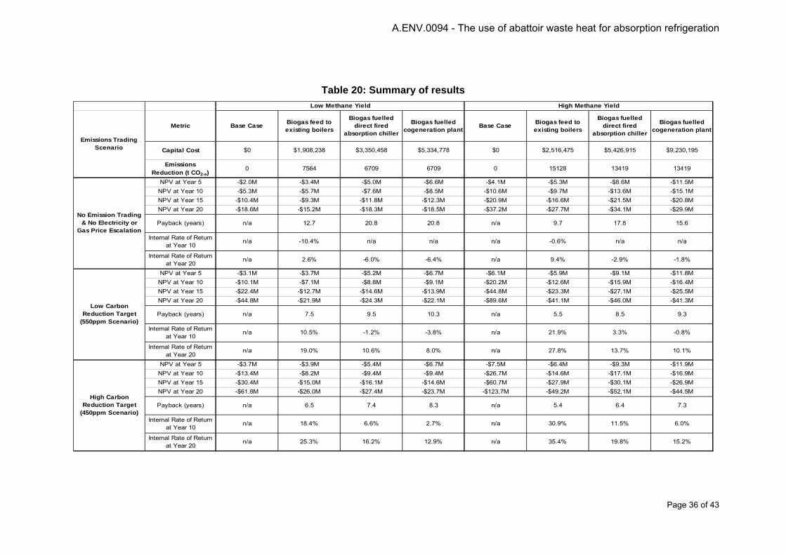
Page 36 of 43
Table 20: Summary of results
Metric Base Case Biogas feed to existing boilers
Biogas fuelled direct fired
absorption chiller
Biogas fuelled cogeneration plant Base Case Biogas feed to
existing boilers
Biogas fuelled direct fired
absorption chiller
Biogas fuelled cogeneration plant
Capital Cost $0 $1,908,238 $3,350,458 $5,334,778 $0 $2,516,475 $5,426,915 $9,230,195
Emissions Reduction (t CO2-e)
0 7564 6709 6709 0 15128 13419 13419
NPV at Year 5 -$2.0M -$3.4M -$5.0M -$6.6M -$4.1M -$5.3M -$8.6M -$11.5MNPV at Year 10 -$5.3M -$5.7M -$7.6M -$8.5M -$10.6M -$9.7M -$13.6M -$15.1MNPV at Year 15 -$10.4M -$9.3M -$11.8M -$12.3M -$20.9M -$16.6M -$21.5M -$20.8MNPV at Year 20 -$18.6M -$15.2M -$18.3M -$18.5M -$37.2M -$27.7M -$34.1M -$29.9M
Payback (years) n/a 12.7 20.8 20.8 n/a 9.7 17.8 15.6
Internal Rate of Return at Year 10
n/a -10.4% n/a n/a n/a -0.6% n/a n/a
Internal Rate of Return at Year 20
n/a 2.6% -6.0% -6.4% n/a 9.4% -2.9% -1.8%
NPV at Year 5 -$3.1M -$3.7M -$5.2M -$6.7M -$6.1M -$5.9M -$9.1M -$11.8MNPV at Year 10 -$10.1M -$7.1M -$8.8M -$9.1M -$20.2M -$12.6M -$15.9M -$16.4MNPV at Year 15 -$22.4M -$12.7M -$14.6M -$13.9M -$44.8M -$23.3M -$27.1M -$25.5MNPV at Year 20 -$44.8M -$21.9M -$24.3M -$22.1M -$89.6M -$41.1M -$46.0M -$41.3M
Payback (years) n/a 7.5 9.5 10.3 n/a 5.5 8.5 9.3
Internal Rate of Return at Year 10
n/a 10.5% -1.2% -3.8% n/a 21.9% 3.3% -0.8%
Internal Rate of Return at Year 20
n/a 19.0% 10.6% 8.0% n/a 27.8% 13.7% 10.1%
NPV at Year 5 -$3.7M -$3.9M -$5.4M -$6.7M -$7.5M -$6.4M -$9.3M -$11.9MNPV at Year 10 -$13.4M -$8.2M -$9.4M -$9.4M -$26.7M -$14.6M -$17.1M -$16.9MNPV at Year 15 -$30.4M -$15.0M -$16.1M -$14.6M -$60.7M -$27.9M -$30.1M -$26.9MNPV at Year 20 -$61.8M -$26.0M -$27.4M -$23.7M -$123.7M -$49.2M -$52.1M -$44.5M
Payback (years) n/a 6.5 7.4 8.3 n/a 5.4 6.4 7.3
Internal Rate of Return at Year 10
n/a 18.4% 6.6% 2.7% n/a 30.9% 11.5% 6.0%
Internal Rate of Return at Year 20
n/a 25.3% 16.2% 12.9% n/a 35.4% 19.8% 15.2%
High Methane Yield
No Emission Trading & No Electricity or
Gas Price Escalation
Low Carbon Reduction Target
(550ppm Scenario)
High Carbon Reduction Target
(450ppm Scenario)
Emissions Trading Scenario
Low Methane Yield
A.ENV.0094 - The use of abattoir waste heat for absorption refrigeration

Page 37 of 43
-$20
-$18
-$16
-$14
-$12
-$10
-$8
-$6
-$4
-$2
$-
2010 2012 2014 2016 2018 2020 2022 2024 2026 2028 2030
Mill
ions
Year
NPV
Base CaseBiogas Absorption ChillerBiogas Boiler FeedBiogas Cogeneration
Figure 14: Discounted cash flow – low methane yield, no emissions trading
-$50
-$45
-$40
-$35
-$30
-$25
-$20
-$15
-$10
-$5
$-
2010 2012 2014 2016 2018 2020 2022 2024 2026 2028 2030
Mill
ions
Year
NPV
Base CaseBiogas Absorption ChillerBiogas Boiler FeedBiogas Cogeneration
Figure 15: Discounted cash flow – low methane yield, 550 ppm scenario
A.ENV.0094 - The use of abattoir waste heat for absorption refrigeration

Page 38 of 43
-$70
-$60
-$50
-$40
-$30
-$20
-$10
$-
2010 2012 2014 2016 2018 2020 2022 2024 2026 2028 2030
Mill
ions
Year
NPV
Base CaseBiogas Absorption ChillerBiogas Boiler FeedBiogas Cogeneration
Figure 16: Discounted cash flow – low methane yield, 450 ppm scenario
-$40
-$35
-$30
-$25
-$20
-$15
-$10
-$5
$-
2010 2012 2014 2016 2018 2020 2022 2024 2026 2028 2030
Mill
ions
Year
NPV
Base CaseBiogas Absorption ChillerBiogas Boiler FeedBiogas Cogeneration
Figure 17: Discounted cash flow – high methane yield, no emissions trading
A.ENV.0094 - The use of abattoir waste heat for absorption refrigeration
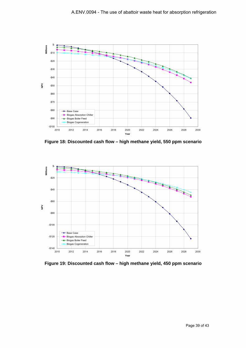
Page 39 of 43
-$100
-$90
-$80
-$70
-$60
-$50
-$40
-$30
-$20
-$10
$-
2010 2012 2014 2016 2018 2020 2022 2024 2026 2028 2030
Mill
ions
Year
NPV
Base CaseBiogas Absorption ChillerBiogas Boiler FeedBiogas Cogeneration
Figure 18: Discounted cash flow – high methane yield, 550 ppm scenario
-$140
-$120
-$100
-$80
-$60
-$40
-$20
$-
2010 2012 2014 2016 2018 2020 2022 2024 2026 2028 2030
Mill
ions
Year
NPV
Base CaseBiogas Absorption ChillerBiogas Boiler FeedBiogas Cogeneration
Figure 19: Discounted cash flow – high methane yield, 450 ppm scenario
A.ENV.0094 - The use of abattoir waste heat for absorption refrigeration

Page 40 of 43
Conclusion
A case study of biogas utilisation in an existing meat processing plant has been undertaken. The case study considered the following biogas utilisation options:
• Option 1 – Biogas feed to existing steam boilers• Option 2 – Biogas-fuelled direct-fired absorption chiller• Option 3 – Biogas-fuelled cogeneration with waste heat absorption chiller
The options were sized and installation and operating costs estimated for various biogas yield rates.
A life cycle cost assessment was undertaken and compared to a business as usual base case under various proposed emissions trading schemes and with varying utilities price escalation scenarios.
From these life cycle assessments it can be concluded that:
1. If no price is placed on emissions, either through an emissions trading scheme or someother mechanism, it is unlikely that any of the proposed options would be financiallyviable due to low or negligible returns on investment.
2. Under either a low emissions reduction target or higher emissions reductions targetutilising the biogas in the boilers of an existing plant provides the highest return oninvestment, mainly due to the relatively low capital cost compared to the other options.
3. In the case of a new plant or a plant requiring replacement of existing refrigeration plantwhere some of the capital cost for the direct-fired absorption chiller could be offset bydown-sizing the conventional plant then this option may be more attractive financially thanthe biogas boiler feed option.
4. Whilst the cogeneration plant has the lowest net present value of all the options over thelife of the plant, due to its high initial capital cost and ongoing maintenance costs thisoption generally shows the lowest return on investment
A.ENV.0094 - The use of abattoir waste heat for absorption refrigeration

Page 41 of 43
5 Conclusions and Recommendations
Anaerobic ponds treating abattoir effluent can be covered to reduce odours and the biogas collected for use as a fuel. Biogas is approximately 65% methane and the yield of methane from abattoir ponds should be in the range 0.15 to 0.3 m3/kg COD removed. The methane could be used to power a gas engine to generate electricity and the exhaust heat used for absorption refrigeration. Alternatively the biogas could be utilised in a directly fired absorption plant or fed to a gas-fired boiler.
Packaged water-lithium bromide absorption refrigeration equipment is available and is the most appropriate technology but most suited to air conditioning applications as it can produce chilled water at a temperature no lower than about 4°C. This limits its application in meat plants but it could be used in office or process area cooling or to produce chilled water for spray chilling of carcases.
Economic evaluation in hypothetical situations and a case study of an actual plant indicate that the very high capital and maintenance costs of cogeneration equipment result in very long payback periods. The other options of direct firing the absorption plant or using the biogas in an existing boiler are more attractive. Due to the high capital cost of the absorption plant, the viability of the investment would still rely on the cost of carbon emissions being above about $30 per tonne CO2-e. Utilising the biogas directly in the boilers provides the highest return on investment, mainly due to the lower capital cost.
While absorption refrigeration systems do not appear to be an attractive investment under the current electricity pricing and emissions regime, this situation is likely to change in the future. Even without a charge on emissions, electricity prices in some areas could increase at a rate well above that of the CPI. It is therefore recommended that:
1. Where the capital cost of conventional ammonia refrigeration can be offset, such as theconstruction of a new plant a major expansion to an existing plant, that absorptionrefrigeration be considered.
2. As development of packaged absorption refrigeration equipment is continuing and pricesrelative to conventional ammonia systems may be more competitive in future, thistechnology should be re-assessed at a later date.
A.ENV.0094 - The use of abattoir waste heat for absorption refrigeration

Page 42 of 43
6 Bibliography Bailey O., Ouaglal B., Bartholomew E., Marnay C., and Bourassa N., An Engineering-Economic
Analysis of Combined Heat and Power Technologies in a μGrid Application, prepared for the United States Environmental Protection Agency by, Ernest Orlando Lawrence Berkeley National Laboratory, Berkeley, California, USA, March 2002
Bliss, P.J. (1995). Anaerobic sludge digestion. In: Principles of Wastewater Treatment. International Winter Environment School, 26-30 June 1995. University of Queensland.
Borja, R., Banks, C.J. & Wang, Z. (1995). Effect of organic loading rate on anaerobic treatment of slaughterhouse wastewater in a fluidised-bed reactor. Bioresource Technology 52, 157-162.
Durbin T.E., and Caponegro M.A., “User guide for desiccant dehumidification technology” USACERL FEAP User Guide 97/107, July 1997
Eckenfelder, W.W. (1989). Industrial Water Pollution Control, Second Edition. McGraw-Hill Book Company.
Henning H-M (2007), Solar Air conditioning and Refrigeration, Task 38 of the IEA Solar Heating and Cooling Programme, presentation to Sustainability Victoria, May 14, 2007
Meat Research Corporation (1997). Treatment of abattoir wastewater using covered anaerobic lagoons: Project M665.A. Envirofacts, Vol. 3 No. 4.
Midwest CHP Application Center (2003). Combined Heat & Power (CHP) Resource Guide. Midwest CHP Application Center.
National and greenhouse energy reporting system measurement – technical guidelines for the estimation of greenhouse gas emissions by facilities in Australia, June 2009. http://www.climatechange.gov.au/~/media/publications/greenhouse-report/nger-measurement-technical-2009.ashx
Oak Ridge National Laboratory (2004). Guide to Combined Heat and Power Systems for Boiler Owners and Operators. Oak Ridge National Laboratory, Tennessee.
Peckmann H., Jakob U., "Solar Cooling Kits im kleinen Leistungsbereich", Fachforum Klimatisierung mit Solarenergie, Bauzentrum München, Germany, September 2008, http://www.solarnext.eu/pdf/ger/publications_presentations/jakob/08FachforumKlimatisierung_Solar_Cooling_Kits.pdf, accessed December 2008
Probert J.M., and Riley S.D., “Carbon-dioxide emissions from an integrated small-scale CHP and absorption chiller system”, Applied Energy 61 (1998) p 193-207
Preisler A., “Reduction of Costs of Solar Cooling Systems”, Final Report, European Project TREN/05/FP6EN/SO7.54855/020094, June 2008
Rafferty, Kevin (1998), Absorption Refrigeration, Chapter 13, Geothermal Direct Use Engineering and Design Guidebook, Third Edition, Geo-Heat Center, Oregon Institute of Technology, Klamath Falls, OR
A.ENV.0094 - The use of abattoir waste heat for absorption refrigeration

Page 43 of 43
Renewable Energy Act (Electricity) 2000 as amended, http://www.comlaw.gov.au/ComLaw/Legislation/ActCompilation1.nsf/0/909E016D7E5B42E3CA257633001C202A/$file/RenewableEnergyElectricityAct2000.pdf
Resource Dynamics Corporation, “Integrated Energy Systems (IES) for Buildings: A Market Assessment”, Prepared for: Energy Efficiency and Renewable Energy U.S. Department of Energy Washington, DC and Oak Ridge National Laboratory, August 2002
Stafford, D.A., Hawkes, D.L. & Horton, R. (1980). Methane Production from Waste Organic Matter. CRC Press, Inc.
UK DETR Introduction to Absorption Chillers, 2001, page 31
US Navy, “Advantages and Disadvantages of Using Absorption Chillers to Lower Utility Bills”, TechData Sheet TDS -2041-E&U, April 1997
US Department of Energy, “Two-Wheel Desiccant Dehumidification System” Federal Technology Alert, http://www1.eere.energy.gov/femp/pdfs/FTA_two-wheel.pdf accessed 16 December, 2008
Wang R.Z. and Oliveira R.G., “Adsorption refrigeration – an efficient way to make good use of waste heat and solar energy”, Proc Int. Sorption Heat Pump Conference, Denver, Colorado, USA, June 2005
www.colibri.bv.com/techinfo.html, accessed March 2009
A.ENV.0094 - The use of abattoir waste heat for absorption refrigeration