final report of the first step-nc project
TRANSCRIPT

2002 by STEP-NC consortium Author(s): Mueller P.;Y.T. Hyun (WZL)
ESPRIT Project EP 29708STEP-Compliant Data Interface for Numerical Controls ( STEP-NC )
STEP-NC
Final Report
Version 1 - Nov. 2001
Document: KFINAL_REPORT.DOC
Status: Draft
Access: Public

STEP-NCFinal Report
STEP-NC consortium, EP 29708 Public Draft Version 1 - Nov. 2001 - Page i
Table of contents
1 Project Overview ...........................................................................................................1
2 Project Objectives .........................................................................................................2
3 Methodology..................................................................................................................2
4 Project Achievements ...................................................................................................5
4.1 Results of testing of the machining scenarios .........................................................................6
4.2 Results of testing of enhanced CAM functions .....................................................................17
4.3 Conclusion ...........................................................................................................................21
4.4 Relations with other relevant projects...................................................................................22
4.5 Implications on Standards.....................................................................................................23
4.6 Benefits to Society ................................................................................................................24
5 Deliverables and References......................................................................................24
5.1 Project documentation ..........................................................................................................25
5.2 Project Management.............................................................................................................25
5.3 References to dissemination activities ..................................................................................25
6 Outlook.........................................................................................................................26
7 Annex ...........................................................................................................................27
7.1 Deliverables .........................................................................................................................27
7.2 Articles, Conferences, Presentations.....................................................................................28

STEP-NCFinal Report
STEP-NC consortium, EP 29708 Public Draft Version 1 - Nov. 2001 - Page 1 of 28
1 Project Overview
The main achievement of the project was to develop a data interface for the process chainbetween computer aided design (CAD) and the manufacturing of the developed product on acomputerised numerically controlled machine tool (CNC). A study had shown that savings in thecreation of a CNC program up to 50% might be possible by:
• Improved data flow between CAD and shop floor allowing bi-directional data flow
• Avoiding post processors
• Machine independent data allowing flexible re-scheduling.
Such a new data model for the interfacing was developed, implemented, tested andstandardised.
Basis for the interface was the geometry data created in a CAD system which was enriched withtechnology data and the sequence of the work of the machine tool. Figure1.
Figure 1: Structure of the new data model
As specification for the data format the Product Data Management Standards ISO 10303 AP203,AP214 and AP224 were chosen. These standards are used for the exchange of information inautomobile and aircraft industries, the major users of CNC machines.
For the realisation partners of every step of the process chain between CAD and CNC machinetool have been involved:
Computer aided design: Dassault
Computer aided manufacturing: Dassault, Openmind, CADCAMation
Comuterized Numerical Control: Agie, OSAI, SIEMENS AG
Main programmefile
A
Three Parts of theProgramming Interface
Object-oriented descriptionof the data referenced in (A):
technology, tools,reference to geometry
description in (C)
Textual descriptionof the tasks
Description of thegeometry usingSTEP syntax
User accesses system usinggraphic interface
("shopfloor programming")
references
refe
renc
es
Technologydescription
B
Geometrydescription
C40
80
32
64 32

STEP-NCFinal Report
STEP-NC consortium, EP 29708 Public Draft Version 1 - Nov. 2001 - Page 2 of 28
Machine Tool Builder: Agie, Starrag, CMS
User: DaimlerChrysler, Volvo, Derendinger, Franci, Wyss
University: EIG, ISW, WZL
Consultant standardisation: AMT
It was taken care that both possibilities of programming, programming in a job preparation andshop floor programming were involved.
The developed and tested data models were fixed in an ISO standard ISO DIS 14649. The firsttechnology milling is now under distribution as FDIS.
2 Project Objectives
Main objective for the project was the development of the data model for the interface of theCNC for the technologies:
• Milling
• Turning
• Contouring
• EDM
The technology grinding was excluded because a first study showed that a lot of manualinteractions hamper the automatic flow and that the process dependency of the data is very high.
The developed interface for the other technologies should be tested by prototypeimplementations at the CAM and at the CNC level.
The prototypes should be tested and validated at real machines with suitable workpieces. Afterthe validation the data model should be fixed in an international standard.
3 Methodology
Basis for the project work was the activity “Product Data Management” of the automotive andaircraft industry. First hints for a solution of the modelling could be found in the “Optimal” project,in studies of DaimlerChrysler and in the standardisation work of the working group7 of ISOTC184 SC1. Therefore the following steps for the proceeding in every technology were chosen:
• Collection of demands of suppliers and users
• Elaboration of the data model
• Elaboration of a scenario and test workpieces for the realisation
• Implementation of demonstrators
• Test and evaluation of the process chain
Due to the most relevant information the first scenario developed was the scenario for milling(2,5D) and drilling. There the know how elaborated was the most mature one and the demandshad been collected during the start period of the project.

STEP-NCFinal Report
STEP-NC consortium, EP 29708 Public Draft Version 1 - Nov. 2001 - Page 3 of 28
The data model covers the whole applications of milling (2,5 and 3D). Figure 2.
The machining features describe what the machine shall do and the workingsteps with theoperations describe how the features should be manufactured.
Figure 2: Part of the schema of the data model
The description of the data model was done with the language “EXPRESS” which wasdeveloped for this kind of work. The benefit of this language is that it can be used directly forparsers or other kinds of computing.
During the realisation of the prototypes a lot of clarifications were necessary because everythingwas under construction and everything could include misinterpretations. Therefore it was veryhelpful to use a common parser developed from WZL because so the data base used wasidentically. Due to the test results a bigger rework of the data model was necessary. At the endthe solution found had also a big impact to the AP standards of ISO 10303 , especially AP224. Itwas found that there are existing gaps in the feature definition which must be closed by acommon harmonisation of the standards. It cannot be avoided that this changes will have alsoinfluence to the developed data model.
This actions demonstrate that it is absolutely necessary to realise test implementations for such akind of modern standards. Creating only theoretical data models will never fit the needs of theapplications of the users especially if they are as complex as in our case.
So scenarios for the realisation were drafted. The scenario configurations show the data flowand the description of the work which should be done by the partners. Included were also testwork pieces for the validation of the process chain.
workpiece
machining_feature
S[0:?]
pocket plane regionhole
1 S[0:?]
machining_operation
workplan
machining_workingstep
L[0:?]
plane_milling side_milling drilling
1
tool
technology
strategy
L[0:?]
cutter_contact_trajectory parameterised_pathcutter_location_trajectory
1
toolpath
geometry
geometry
geometry

STEP-NCFinal Report
STEP-NC consortium, EP 29708 Public Draft Version 1 - Nov. 2001 - Page 4 of 28
For the first implementation of the controller a human interface for manipulating and testing thedata model was necessary to be developed. For getting the first experience with this newinterface a rapid prototyping was done in VisualBasic. The prototype was presented to thepartners and alternatives were discussed. The second prototype in c++ was based on theexperience made. By that way the development time could be shortened because some iterationloops could be saved. For the implementation of the features a stepwise development wasrealised. So it was possible to test the first features very early and the partial functionality wasincreased from release to release. For the first scenario 23 releases were necessary to reachthe functionality needed for the machine tests.
During the tests the geometry data were imported into the CAM systems. After a featurerecognition the necessary sequence of the workinsteps, the tooling and the technology datawere added. By simulation at the CAM system the functionality of the program was tested. Thepositive result was transmitted to the CNC where a test with the real tool set of the machine wasdone. Necessary changes due to setup or technological data could be performed directly at thecontrol. After a positive simulation the workpieces were cut.
This principle was followed in general in all scenarios. A overview of scenarios shows thefollowing list:
Scenario Technology CAM system Control /Machine Workpiece
Scenario 1 Milling and Drilling
2,5 D
Dassault
Openmind
Siemens 840D/
Hermle, Chiron
DC– workpiece,
Volvo Vamos,
Complex pocket
Scenario 2 3D Openmind Selca/Franci Franci workpiece
Scenario 3 Contouring wood CMS OSAI/CMS Kitchen door,
Clock housing
Scenario 4 Wire EDM Agie (EPFL) Agie/Agie Die plate withwatch contour
For the technology turning no scenario was realised. Due to the first schedule this technologywas planned to be elaborated from US partners but the shifted start of the US project made itnecessary to take over the modelling work. The model itself is developed and introduced into thestandardisation.
The tests on the machine tool and the cutting of workpieces has been very sumptuous. Thereason for the time consuming machine test is the setup of the whole machine tool, thepreparation of the fixtures, the tooling, the preparation of the rawpieces and the maintenance ofthe machine. Therefore the tests were done mostly on a simulation based on the standard CNCenhanced with the new software. So very early and with not much time consuming simulationsnew software from the CAM partners could be evaluated. Feed back with hints for differentinterpretations took not very much time.
The tests and the results were documented by videos and photos which are collected on a demoCD.

STEP-NCFinal Report
STEP-NC consortium, EP 29708 Public Draft Version 1 - Nov. 2001 - Page 5 of 28
4 Project Achievements
During the project the data models for milling, drilling, turning, contouring and EDM could berealised. The functionality of the new interface was proved in 4 scenarios which realised theprocess chain for the respective technology. The validation was done by creation of programs forthe new interface and the manufacturing of test parts on machines equipped with controls whichwere developed in this project. The goals of the project could be reached in every aspect.
In detail the following prototypes were developed and validated:
AGIE: Frontend STEP-CNC for EDM together with CADCAMation and EPFL
CADCAMation: CAM – station for EDM
CMS: Prototype machine with STEP-NC for wood glass and stone, application contouring.
Dassault: CAM – station for milling and drilling with 2,5 d movements
Openmind: CAM – station for milling and drilling with 2,5 d movements, interface to Vamos
OSAI: STEP-CNC for wood, glass and stone
Siemens: STEP-CNC for milling and drilling with 2,5 d movements
Test group:
DaimlerChrysler: Milling and drilling at Hermle and Chiron machines
Franci: Milling and contouring with frontend solution and legathy code
Progetti: Milling and contouring with frontend solution and legathy code
Volvo: Milling and drilling at Hermle and Chiron machines, interface to Vamos
Wyss: EDM applications
Institutes:
EIG i-tech: Software tools for EDM
EPFL: Software for EDM, AGIE frontend
ISW Stuttgart: Development of turning model
WZL Aachen: Elaboration of milling and drilling model, development of milling applications
Consulting:
AMT: Standardisation ISO TC184 SC1 WG7 and SC4
The new data models were tested for compatibility with the standards ISO 10303 AP224 andwere integrated in a new ISO standard DIS 14649. The first part for milling and drilling got apositive vote and the publication is initialised. The voting of the other parts will be done as a nextstep.

STEP-NCFinal Report
STEP-NC consortium, EP 29708 Public Draft Version 1 - Nov. 2001 - Page 6 of 28
4.1 Results of testing of the machining scenarios
Due to the early preparations of the data model, the first realisation was started for milling. So theother scenarios were built after the first machining test with a milling machine.
4.1.1 Scenario 1 for milling and drilling
Figure 3 shows the specification of scenario 1.
Figure 3: Scenario 1 for milling application
To test different program sources, two input data streams from VAMOS and from CATIA werechosen. The design of the test parts was done by DaimlerChrysler and Volvo. The data wereused from Dassault and Openmind CAM stations where the features were identified and addedwith the necessary technological information like feed, spindle speed and the kind of operation.The CAM- stations of Openmind and Dassault are shown in figure 4 and 5.
VAMOS
STEP-NC
CATIA V5 Open Mind
Siemens 840D
Open Mind CATIA NC UserInterface
Control
Siemens
STEP-NC InterpreterNC Machine
Partner Role
Siemens build prototype nc controller based on 840DDaimlerChrysler user test and validation, 2.5D machiningDassault StepNC Output for CATIA V5 Manufacturing for 2.5DOpenMind StepNC Output for 3D NC programming environmentVolvo user test and validation, 3D machining
Partner Role
Siemens build prototype nc controller based on 840DDaimlerChrysler user test and validation, 2.5D machiningDassault StepNC Output for CATIA V5 Manufacturing for 2.5DOpenMind StepNC Output for 3D NC programming environmentVolvo user test and validation, 3D machining
Application:Milling, Drilling, 2.5D + 3D

STEP-NCFinal Report
STEP-NC consortium, EP 29708 Public Draft Version 1 - Nov. 2001 - Page 7 of 28
Figure 4: CAM – Station Dassault based on CATIA V
Figure 5 CAM – Station Openmind

STEP-NCFinal Report
STEP-NC consortium, EP 29708 Public Draft Version 1 - Nov. 2001 - Page 8 of 28
The output of the CAM stations was the new interface code as developed in the project andfixed in the new standard ISO DIS 14649.
Figure 6 shows one of the test machines used for the validation. The Hermle machine wasequipped with automatic tool changer so that all the technological surrounding could be tested.
Figure 6: Hermle Test machine with STEP-CNC
To show that the code is independent from the machine tool there were also tests with a Chironmachine and a Maho machine. So it was demonstrated that no postprocessor is necessary.One difficulty was the supply of the machines with the tools according to the programs. Thesetup work for the cutting of a work piece pointed out how necessary a standard is needed forthe tool description. It was arranged that the standardisation group responsible for tools got allthe information for their work. In the meantime the missing tool description was incorporated intoISO DIS 14649.
Figure 7 and 8 show the results of the machine tests. In addition to this work pieces tests ofpocketing and different sequences of machining operations were done. The functionality of thescenario realised allowed to cut every feature but sometimes restrictions were found whichreduced the free selection of the technological possibilities.

STEP-NCFinal Report
STEP-NC consortium, EP 29708 Public Draft Version 1 - Nov. 2001 - Page 9 of 28
Figure 7: Test workpiece data imported from Vamos
Figure 8 : Test work piece with the most important features

STEP-NCFinal Report
STEP-NC consortium, EP 29708 Public Draft Version 1 - Nov. 2001 - Page 10 of 28
4.1.2 Scenario for freeform surfaces Progetti / Franci
The scenario demonstrated the work with the new interface together with the legathy code ofthe controls used at Franci. The tasks for the scenario are shown in figure 9 and 10.
A part designed by Franci was programmed by Openmind. The selected geometries for thetests can be seen in figure 11. Main goal was the cutting of the freeform part. The Openmindcode was compiled by a prototype postprocessor into the legathy code.
STEP-NC
Solid Parts
Open Mind
Open Mind NC UserInterface
Iso postprocessor
3 2
2
X = Tasks
5 Axis NC Machine
Surf Parts 1
ProductionPhase
DesignPhase
Figure 9: Scenario 2
Task No Task Description Leading Partner Involved Partner
1 Generation of prismatic and free-form 3D parts
Programming
Franci Progetti
Openmind
2 Test of user interface Franci Progetti Franci Progetti Derendinger
3 Test of milling path Franci Franci Progetti Derendinger
Figure 10: Task Specification of scenario 2
The prototype postprocessor was built from EPFL based on the parser of WZL. In paralell Progettibuilt a simple converter of the ISO 14649 file entity “TOOLPATH” generating the geometryinformation of the machine.

STEP-NCFinal Report
STEP-NC consortium, EP 29708 Public Draft Version 1 - Nov. 2001 - Page 11 of 28
Figure 11: Test workpiece Scenario 2
Freeform ( Ball tooldia.32.00 or 20.00)
Pocket ( Flat tooldia.30.00 )
Holes
Holes
STEP-NCFinal Report
STEP-NC consortium, EP 29708 Public Draft Version 1 - Nov. 2001 - Page 12 of 28
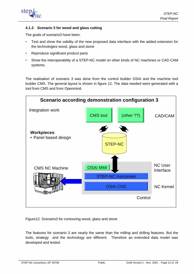
4.1.3 Scenario 3 for wood and glass cutting
The goals of scenario3 have been:
• Test and show the validity of the new proposed data interface with the added extension forthe technologies wood, glass and stone
• Reproduce significant product parts
• Show the interoperability of a STEP-NC model on other kinds of NC machines or CAD CAMsystems.
The realisation of scenario 3 was done from the control builder OSAI and the machine toolbuilder CMS. The general layout is shown in figure 12. The data needed were generated with atool from CMS and from Openmind.
Figure12: Scenario3 for contouring wood, glass and stone
The features for scenario 3 are nearly the same than the milling and drilling features. But thetools, strategy and the technology are different. Therefore an extended data model wasdeveloped and tested.
Scenario according demonstration configuration 3
STEP-NC
CMS tool (other ??)
OSAI CNC
NC UserInterface
Control
CAD/CAM
OSAI MMI
STEP-NC Interpreter
Workpieces:• Panel based design
NC Kernel
Integration work
2
4
CMS NC Machine

STEP-NCFinal Report
STEP-NC consortium, EP 29708 Public Draft Version 1 - Nov. 2001 - Page 13 of 28
Figure 13 shows the machine tool used for the tests. It is a CNC machine from CMS equippedwith a control from OSAI. For the programming there are no standard CAM systems on themarket. Every machine tool builder has his own solution. So CMS implemented also thenecessary software for the CAM part.
Figure 13: Test machine CMS Zogno/Italy equipped with OSAI control
Figure 14: Test part “kitchen door”
STEP-NCFinal Report
STEP-NC consortium, EP 29708 Public Draft Version 1 - Nov. 2001 - Page 14 of 28
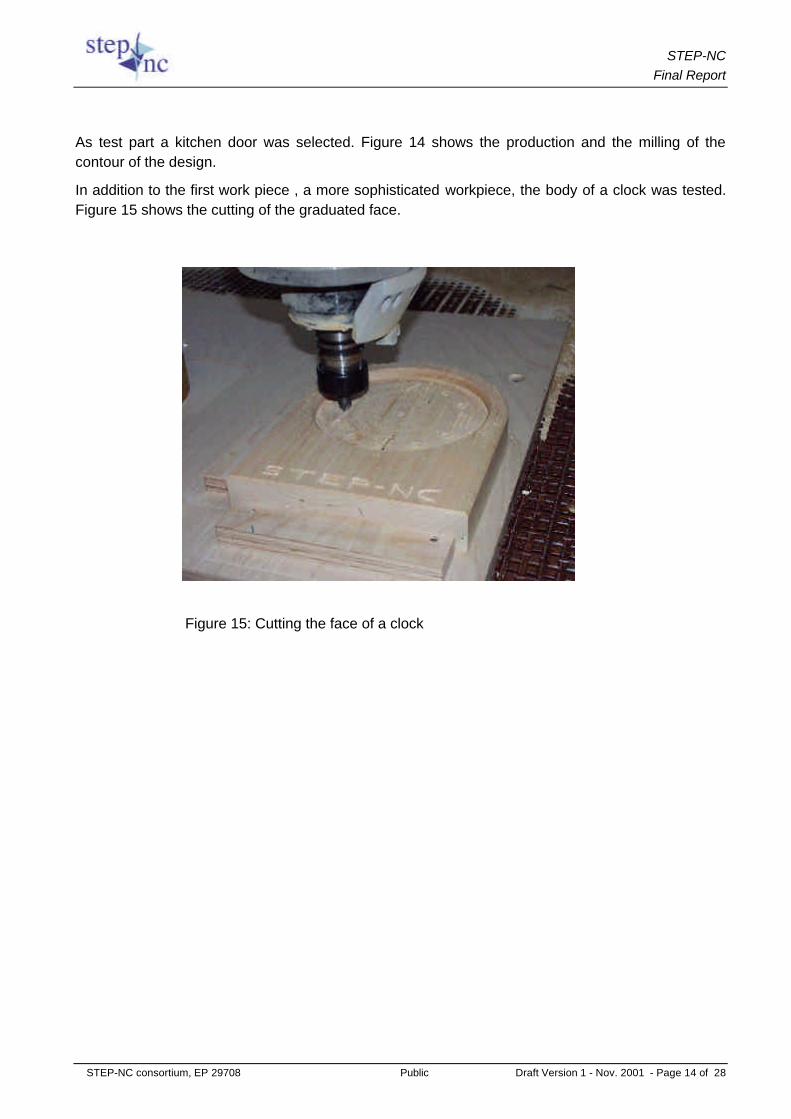
As test part a kitchen door was selected. Figure 14 shows the production and the milling of thecontour of the design.
In addition to the first work piece , a more sophisticated workpiece, the body of a clock was tested.Figure 15 shows the cutting of the graduated face.
Figure 15: Cutting the face of a clock

STEP-NCFinal Report
STEP-NC consortium, EP 29708 Public Draft Version 1 - Nov. 2001 - Page 15 of 28
4.1.4 Scenario 4 for EDM
The goals of the test scenario 4 are the following:
§ Check the validity of the wire-EDM data model defined in the Work Package 5 of thecurrent project.
§ Check the feasibility of a prototype implementation in a CAD/CAM system and in awire-EDM machine CNC.
§ Check the interoperability of a STEP-NC file on different types of machines(Charmilles Technologies and AGIE).
Figure16: Test scenario 4 principle
Scenario according demonstration configuration 4
STEP-NC
GOélan EDM
AGIEVISION CNC
NC UserInterface
Control
CAD/CAM
AGIEVISION MMI
STEP-NC Interpreter
Workpieces:• 2 contours design• Part with ruled surfaces
NC Kernel
Integration work
5
1
2
3
X = Tasks
AGIECUTwire EDM
4CADCAMationdevelopments

STEP-NCFinal Report
STEP-NC consortium, EP 29708 Public Draft Version 1 - Nov. 2001 - Page 16 of 28
Figure17: Test machine Wire Cut, Charmilles
The test part designed by Wyss for the wire-EDM scenario is a die for watchmakers. Thefollowing design features will be cut by wire EDM processing:
- A vertical cylindrical part
- A conical part with a taper of 2 degrees
Figure 18: Test part for wire EDM

STEP-NCFinal Report
STEP-NC consortium, EP 29708 Public Draft Version 1 - Nov. 2001 - Page 17 of 28
The demonstration of the scenario 4 was executed on 12th December 2001 at CharmillesTechnologies, EDM machine builder in Meyrin (Geneva, Switzerland).
Figure19: Test part result
4.2 Results of testing of enhanced CAM functions
The goals of the project concerning CAM function were :
• To define the scope of future CAM and SFP systems and to identify new functions that could beimplemented in them.
• To choose two intelligent functions that could be implemented in CAM/SFP and to develop thecorresponding algorithms.
• To implement some prototype functions in a CAM system.
• To implement some prototype functions in a SFP system.
In a survey the most interesting functions were collected and rated. The three most needed wereselected and realised. These functions are:
• Simulation of cutting paths and collision check (Openmind)
• Read-in module for feed back of modified NC programs (Dassault)
• Data base for program distribution and version management (WZL)

STEP-NCFinal Report
STEP-NC consortium, EP 29708 Public Draft Version 1 - Nov. 2001 - Page 18 of 28
Simulation
For the simulation it was necessary to take the different kinematics of a machine tool intoconsideration. In the project the normal rectangular kinematics with up to 2 round axes were chosenand can be selected. Figure 20 shows a sample of the collision simulation. The collision ishighlighted using a red dotted line. In parallel the “broken tool” icon is shown in the browser window
Figure20: Simulation of the machine movement with collision check
Database for program management and feed back of programs
The introduction of STEP standard (ISO10303) has brought a better interface between CAD andCAM systems within the planning department. However, it has not been connected down to theshop floor until now. The new data model, STEP-NC, breaks down the walls between planningdepartment and the shop floor and also inside the shop floor. As the STEP-NC interface iscompliant with the STEP standard, which is used by CAD/CAM systems, the bi-directionalexchange of information becomes possible.
Among several possible methods described in D3.0 issued in April 2001, implementation of adatabase was selected as a solution to manage the version information of "project" and revisionhistories of object instances. The data model and algorithm were designed as described in thefollowing sub-chapters.
Thanks to this aspect of the STEP-NC interface, last-minute changes or corrections of the partprogram can be directly fed back to the planning department, enabling the exchange ofknowledge between the planning department and the shop floor.

STEP-NCFinal Report
STEP-NC consortium, EP 29708 Public Draft Version 1 - Nov. 2001 - Page 19 of 28
An object-oriented database (OODB), which both CAD/CAM and CNC can access, has beenemployed for the management of revision. In this database, all entity instances are handled asseparate records. It means that all entity instances defined in the EXPRESS schema of STEP-NCare handled as an object, which can be archived in and retrieved from the object-orienteddatabase.
As illustrated in Figure 21, the STEP-NC OODB was implemented by the use of the POETdatabase. The STEP-NC Parser of WZL is used for the I/O of NC part programs. The mappingbetween the Parser and the database was coded by the use of the POET C++ library. Simpleuser interfaces for the development phase are created by the use of MFC library and Java Appletwhich run on Windows NT 4.0 and Web browser respectively.
Figure 21 Software environment for prototype implementation
For the demonstration of bi-directional exchange of NC programs, a scenario was established asshown in figure 22. Both Siemens 840D CNC controller and CATIA V5 CAD/CAM system canupload and download the STEP-NC file. The version information and revision history is availablefrom the database management system via user-interface in the intranet.
From CAD/CAM to NC controller
Under the work package 2, scenario1, the down stream process of STEP-NC file has beenalready developed and tested.
The primitive STEP-NC program for an example work piece used for scenario 1 of WP2 wasstored into the STEP-NC database. The STEP-NC server registers the NC program along with it'sversion information and status. Siemens 840D controller queries an NC machining "project" fromthe database and gets the corresponding STEP-NC program. Hereby the machine operator caneasily notice the status of the "project" by checking the version information.
User Interface (Java Applet)
STEP-NCpart program STEP-NC
Parser(C++)
POETC++
Library
User Interface (VC++)
- Command to read and write NC files- Command to store and retrieve objects- Dialogs to show the NC file and objects- Dialogs to modify objects
Read
Write
Read & writecommands
Archive &Retrieve
Archive & retrievecommands
RevisionHistoryRevision
History
STEP-NC OODB
Project
Features &OperationsWrite Cutting
tools
- Objects query- Version check- Management of revision history
Instances offeature,
operation,cutting tool, etc.

STEP-NCFinal Report
STEP-NC consortium, EP 29708 Public Draft Version 1 - Nov. 2001 - Page 20 of 28
From NC controller to CAD/CAM
The machine operator modifies the STEP-NC file by using the front-end software of Siemens840D controller. E.g. In a dialog box for drilling operation, for example the cutting depth of drillingis changed to higher value. The STEP-NC database checks the modified NC file and reports onthe version information including revised data by the use of the user interface.
Figure 22 Implementation Scenario
Figure 23 illustrates the principle of bi-directional exchange of NC programs in future. VariousCAD/CAM/CNC systems in local or external site can be linked to the STEP-NC server where theNC programs are efficiently managed and the distributed knowledge is encapsulated andanalysed for reuse.
DBMS• object query• object store• syntax check of STP• Version management
User Interface on the Web browser• Upload NC program• Download NC program• Show objects and version histories
STP
Implementation Scenario
Write-out STP
Read-in STP
Write-out STP
Read-in STP
CATIA V5 Siemens 840D
STEP-NC Database•NC programs•Manuf.-features•Manuf.-operations•Revision histories
STEP-NC Server

STEP-NCFinal Report
STEP-NC consortium, EP 29708 Public Draft Version 1 - Nov. 2001 - Page 21 of 28
Figure 23 Principle construction of b-directional exchange of data
4.3 Conclusion
The tests demonstrated the usability of the new process chain and endorsed the expectedbenefits:
• No postprocessor is necessary
• Closed process chain between CAD and CNC
• No geometry programming of the workpiece is necessary
• Upload of program changes and reuse is possible
• Best suited for ecommerce
• The expected values of savings (30%) are realistic
The demonstrated scenarios have been the first step for an introduction of the new process chaininto practice.
The next step must be a broader use of prototypes. For this step the solutions have to beimproved due to the results of testing. This will increase the acceptance of the market.
CAM
#1=WORKPIECE(. . .);#2=SETUP(. . .);#3=ROUND_HOLE(. . .);#4=CUTTING_TOOL(. .);. . .
CAD Technologies
Cutting ToolsTechnologies
Machine 1
Machine 2Shop floor A Shop floor B
Machine 4
Machine 3
Cutting ToolsTechnologies
+ Correlation management for geometry and technology data+ Version management of NC programs+ Intelligent mechanisms to feedback the shop floor modifications+ Knowledge-sharing between several shop floors and planning departments
XML(WWW)
EXPRESS(STEP P21)
XML(WWW)
EXPRESS(STEP P21)
<WORKPIECE><ID>Test Part 2</ID>. . .</WORKPIECE>….
bi-directional
bi-directional

STEP-NCFinal Report
STEP-NC consortium, EP 29708 Public Draft Version 1 - Nov. 2001 - Page 22 of 28
For the broad use in plants the prototype solutions must be integrated into the standard productsalong with smaller improvements. The savings in the new process chain are a challenge to beintroduced.
4.4 Relations with other relevant projects
The project results brought us into a close collaboration with groups active in this field around theworld:
USA
In the US one year after the start of our project a project called Supermodel was started. Leaderof the project is Prof. Hartwig owner of the company Steptools. We have close contact to him bythe standardisation meetings.
Prof. Hartwigs goal is to develop software for STEP-NC and he announced to have a prototypefor a lathe end of the year 2001. For the realisation he has chosen a slightly different way. Hemapped the new standard in an “Application integrated model” and is going to do hisimplementations on his toolware. The difference between his solution and our implementations isthat he prefers to use a solution based on information technology and we preferred to do the jobmore technology oriented. The comparison of results when they arise will be fruitful for both.
Integrated into the activities is also a group called OMAC (Open Modular Architecture Controls) inwhich the most important users from Automotive and aircraft industries are involved.Implementation plans for applications are under discussion for the year 2002.
Korea
The Korean government has founded a research centre for the new process chain includingSTEP-NC. The institute is very active and is collaborating with the university Stuttgart in themodelling for turning. They have elaborated some technological gaps in comparison to the millingtechnology. The solutions of this gaps may change in some points the modelling of the othertechnologies. It is necessary to discuss this results deeply with specialists because similarproblems are just solved in the milling model.
It is a problem for the Korean developers that they do not have interested and powerful CAM andcontrol manufacturer. So the practical test of the theoretical results is sometimes difficult. It wouldbe helpful to intensify the relation to the institute and to exchange data which may be tested inGermany if there are controls and machines available.
Japan
Since summer of this year the government is sponsoring a 7 years program with the title “DigitalMaster”. Goal of the project is the process chain from CAD to CNC but with first emphasis onCAM activity. Details are not known but it seems to be a goal to get a closer connection betweenCAM and CNC. The results of the work can be seen in the input to the standardisation in ISOTC184 SC1 and SC4.

STEP-NCFinal Report
STEP-NC consortium, EP 29708 Public Draft Version 1 - Nov. 2001 - Page 23 of 28
Europe
There are a big variety of actions running which spread out the modelling to all other technologieswhich are not covered now.
Our project is limited to material removal technologies. There we see in the moment our maingoal. Later we will also pick up activities in rapid prototyping and measuring. This are work itemswhich will be tackled by standardisation and are to be seen in close relationship to partsmanufacturing.
4.5 Implications on Standards
On the activities around the world it can be seen that standardisation is the big platform wherethe modelling of product and manufacturing data is tackled. We started the first activity in 1995when we created an international workinggroup and the first standard proposal was distributed in1997. This first draft was the basis for the STEP-NC project and it should be shown that animplementation of this draft can be done economically.
Short after the first draft of the IMS-project the ISO group “Industrial Automation” draw theirattention to the drafted standard. A discussion came up to include it into a new “ApplicationProtocol” of ISO 10303. Due to the close relevance to the technology of the used “PhysicalDevices” the work was continued in the TC 184 SC1 “Physical Devices”.
The implementation work of the project and the tests showed that some redrafting was necessaryto include the necessary CNC functionality.
During this test phase a very intensive discussion began with the US standards bodies.Especially Steptools took a very active part to adopt the drafted standard 14649 to the PDMframework (PDM = Product Data Management) of ISO 10303. They correlated the draft with theelaborated standards ISO 10303 AP 214 and AP 224. By that way gaps could be closed betweenthe PDM standards and the upcoming ISO 14649.
After a fruitful rework of the draft the second DIS version was balloted. Two parts were votedpositive and one negative. After the integration of some additional instances the voting waschanged in positive and the DIS was accepted.
The new ISO DIS 14649 includes 3 parts:
Part 1: Introduction
Part 10: General features
Part 11: Milling and drilling technology
As further results of the project drafts for part 12 “Turning technology” and part 13 “EDMtechnology” are introduced into the relevant working group.
In parallel the mapping tables between 14649 and the relevant 10303 standards were elaboratedas AP 238.

STEP-NCFinal Report
STEP-NC consortium, EP 29708 Public Draft Version 1 - Nov. 2001 - Page 24 of 28
4.6 Benefits to Society
The project work made it possible that the first industrial realisation of this new data model couldbe demonstrated in Europe. It was shown that the new data model functions as a bridge betweenCAD and the CNC at the shop floor. It was shown that the simplifying of the process chain ispossible and that additionally benefits like easier setup, no need of postprocessing and easy backpropagation is achievable.
It was also seen that for a broader use in high productive applications the features for controllingthe processes must be enhanced. A data access to the real time events at the control side mustbe used for decisions in the process control level. It is up to the European users and applicationsimplementers to use this new data model and to earn the described benefits.
The elaborated know how at the partners side can support the manufacturing industry inapplications which are working with machine tools. For the development of manufacturingprograms two CAM supplier have demonstrated their solutions. As input data product data wasused supplied from CAD systems working with ISO 10303 code.
The CAM output code was used on different machine tools equipped with a control with anintegrated new interface. The integration was done based on a well known CNC so that the userhad no problems with the general use. The operator never got into touch with this new datamodel so that the education was reduced to a simple demonstration of the setup.
Concerning the employment the use of the new data model will have no general influence. Thenot needed post processing saves money and resources, but the new process environment withthe challenge of better tooling, automated measuring with feed back of process datacompensates this effect. Stronger will be the influence on quality of life because decisions, setup,exchangeability and the degree of automation are on a higher level. The transparency of dataand the possible support is better because the data sent to the control has much more contentthan the used legacy code.
Due to environment and resources the most important fact will be the higher productivity whichcan be reached. The reason is the automated optimisation and possibility of manipulation of thedata. The working sequence of the program, the technology and the tooling can be changedeasier at the control by the operator. A missing tool means not to stop the whole process. Theaction can be cut out or done with an other tool or done with a different technology. This savesenergy and natural environment.
The savings calculated for the new process chain will be between 30 to 70 % of theprogramming, editing and maintenance of the NC programs. In addition the expenditure for postprocessors and their maintenance will no longer be necessary.
5 Deliverables and References
The major project documentation was done by two kinds of deliverables:
- Project documentation
- Project management

STEP-NCFinal Report
STEP-NC consortium, EP 29708 Public Draft Version 1 - Nov. 2001 - Page 25 of 28
5.1 Project documentation
The first step of the project was a collection of the demands of users and manufacturers towardsthe new data model. The collected data are described in a first document. After that the specificrequirements of the users were put in a specification for the relevant technologies.
For the implementation and test of the demonstrators 4 scenarios were assigned and aschedule for their midterm development was fixed. Parallel to the development of thedemonstrators the data model descriptions of every technology developed was sent to ISO TC184 SC1 WG7 for the integration into the new upcoming standard ISO 14649.
The test of the scenarios, the work pieces produced, results and new ideas for the future workwere documented. The scenario1 which was firstly developed could be tested more in detail. Theresults and the benefits which can be expected by industrial use are put together in a document“Results of usability tests for milling”.
A complete list of the deliverables can be found in Annex I.
5.2 Project Management
The whole project was documented by progress reports which were elaborated every 6 months.The content was :
- Executive Summary
- World-wide “state of the art” update
- Exploitation of results
- Work progress overview
- Clarifications
- Information dissemination activities
- Contractual matters
All documentation of minutes, review results, deliverables and descriptions are archivised on aproject internal web page. In addition a public web page www.step-nc.org serves the generalinformation and is base for an user group.
5.3 References to dissemination activities
A list of the dissemination activities can be found in the Annex.

STEP-NCFinal Report
STEP-NC consortium, EP 29708 Public Draft Version 1 - Nov. 2001 - Page 26 of 28
6 Outlook
The reached status with the new interface technology of CAD/CAM/CNC shows the benefitswhich can be reached. Until now it was very theoretical that there will be an enhancement of theprocess chain. But now the feasibility is demonstrated and major betterments could be shown.
That means that the new technology is still in phase one. The end users must be confirmed bydemonstrating the new process chain. Therefore all the tangible tools necessary have to beworking and available. This is still not 100 % the case. Especially the tools have to be involveddeeper. In this moment only sponsored single implementations have a chance of realisation. Forthis few applications the prototype realisations with small enhancements will be sufficient.
After the availability of the test results of this applications the interest of using the process chainwill grow during phase 2 of exploitation. End users which could test the benefits will get the knowhow for the implementations and the necessary environment. Realisation plans will be made andthe pull after the new technology will grow, small orders will take place. That can start in the years2002 to 2003.
The next phase, is the hot business phase 3 where users are aware of the benefits and try toshare them. For that phase the today’s prototypes have to be enhanced to standard products withhigh reliability. The work to do should not be underestimated and also the environment for theprocess must be ready for use.
During the project a lot of information dissemination by paper and by events has been done. Toget forward in the exploitation phases future work is necessary and so the partners decided toenter into a new international project together with the other regions which are active in this field.
USA, Korea, Swizerland and the EU have signed a contract with shared activities in that area. Inthe next 2 years it is scheduled also to develop prototype implementations for the turning,measuring and the rapid prototyping technology. This gap closing technologies for fullyautomated manufacturing needs also the development of information entities like toleranceswhich will be used for inspection of the manufactured parts.
In Germany the project partners have installed a link to a machine tool builder group which worksfor automotive industry. They claimed to have additional enhanced features for a more real timecontrol of the process. This will also a goal for this international IMS project STEP-NC. Kick-off ofthe project will be early in 2002.

STEP-NCFinal Report
STEP-NC consortium, EP 29708 Public Draft Version 1 - Nov. 2001 - Page 27 of 28
7 Annex
7.1 DeliverablesTypes ofdeliverables
Description of the deliverable (Title) Delive-rablenumber
Work-packagereference
Responsible partner
Projectmonth
YEAR 1Document Demands of manufacturers and users
towards the new interface1.1 WP1,
WP2CMS 6
Document First information dissemination andexploitation report
7.1 WP7 CECIMO 12
Document Specification of user requirements forcontour cutting of wood and glass
4.1 WP4 CMS 12
Document Specification of user requirements forturning, grinding, rapid prototyping
4.2 WP4 Daimler-Benz
12
Document Specification of user requirements for EDM 4.3 WP4 Wyss 12Document Description of mid-term developments in
WP22.0 WP2 Siemens 12
YEAR 2SoftwareDemonstration (2)/Document
Demonstration of prototype of STEP-NCCAM/SFP system
2.1.1 WP2 Open Mind 18
SoftwareDemonstration /Document
Demonstration of prototype of STEP-NCbased CNC
2.1.2 WP2 Siemens 18
Document Description of mid-term developments inWP5
5.0 WP5 EPFL 21
Document Second information dissemination andexploitation report
7.2 WP7 CADCAMation
24
YEAR 3Document Description of mid-term developments in
Task 2.32.0.1 WP2 Volvo 26
Document Description of mid-term development in WP3 3.0 WP3 WZL 26Document Results of usability tests for milling 2.2 WP2 Volvo 36Document Description of new applications developed 3.1 WP3 CADCAMa
tion36
Document Specification of improved data model 3.2 WP3 WZL 36Document Specification of geometry for non-milling
technologies5.1 WP5 OSAI 30
Document Specification of process data for contourcutting of wood and glass
5.2 WP5 WZL 30
Document Specification of language for contour cuttingof wood and glass
5.3 WP5 ISW 30
Document Specification of process data for EDM 5.4 WP5 AGIE 30Document Specification of language for EDM 5.5 WP5 EPFL 30SoftwareDemonstration
Demonstration of prototype of STEP-NCCAD-CAM-CNC chain for contour cutting
6.1 WP6 OSAI 36
SoftwareDemonstration
Demonstration of prototype of CAD-CAM-CNC chain for wire-EDM
6.2.1 WP6 CADCAMation
36
SoftwareDemonstration
Demonstration of prototype of CAD-CAM-CNC chain for sink-EDM
6.2.2 WP6 CADCAMation
36
Document Description of the CAD-CAM-CNC chain 6.3 WP6 CADCAMation
36
Document Final information dissemination andexploitation report
7.3 WP7 Siemens 36

STEP-NCFinal Report
STEP-NC consortium, EP 29708 Public Draft Version 1 - Nov. 2001 - Page 28 of 28
7.2 Articles, Conferences, Presentations
Publication Headline Date
Lecture Aditek: STEP-NC August 1999
Presentation Leuven IMS conference: STEP_NC Sept.1999
Presentation KTH Stockholm: Project STEP-NC Oct. 1999
STEP-NC web site www.step_nc.org January 2000
Lecture ISW Stuttgart STK: STEP-NC Feb. 2000
Newsletter STEP-NC newsletter 1 April 2000
Article Engineering-Workflow: STEP-NC-der nächste Schritt May 2000
Article Production: “Mehr als nur Maschinensteuerung” June 2000
Newsletter STEP-NC newsletter2 July 2000
Demo CD Mr. Glantschnig: First STEP-NC running Sept. 2000
Lecture ProStep Science Days: First STEP-NC Sept. 2000
Article Harvest: “STEP et la commande numerique” Oct. 2000
Presentation ISO Plenary Project STEP-NC Oct. 2000
Presentation DaimlerChrysler: STEP-NC April 2001
Presentation Computer-expo Lausanne: STEP-NC project April 2001
Newsletter STEP-NC newsletter 4 May 2001
Article VDMA News: “Machine tool goes STEP” June 2001
Presentation DaimlerChrysler Auburn Hills: STEP-NC June 2001
Presentation Ludwigsburg Hüller-Hille: STEP-NC for automotive plants August 2001
Seminar EMO fair Hannover: STEP-NC Sept.2001
Lecture VDMA Information day:STEP-NC application Nov. 2001
Seminar UCIMU Milano :STEP-NC Dec. 2001
Lecture ADITEC WZL Aachen: The machine tool goes STEP Jan. 2002