final report no. 2050 by the aircraft accident … private aircraft type amateur-built aircraft...
TRANSCRIPT

Büro für Flugunfalluntersuchungen BFU Bureau d’enquête sur les accidents d’aviation BEAA Ufficio d’inchiesta sugli infortuni aeronautici UIIA Uffizi d'inquisiziun per accidents d'aviatica UIAA Aircraft Accident Investigation Bureau AAIB
Aéropôle 1, Route de Morens, CH-1530 Payerne
Final Report No. 2050
by the
Aircraft Accident
Investigation Bureau
concerning the accident
involving the EXPRESS 2000 ER aircraft, registration HB-YMN
on 23 July 2007
in Basel

Final Report HB-YMN
Aircraft Accident Investigation Bureau Page 2 of 46
Ursachen
Der Unfall ist darauf zurückzuführen, dass das Flugzeug mit Hindernissen kollidierte, weil es auf Grund seiner Masse, seiner Schwerpunktslage und der verfügbaren Leistung nach dem Abheben weder in der Lage war zu beschleunigen, zu steigen noch eine Kurve zu fliegen.
Folgende Faktoren haben zum Unfall beigetragen:
• Der Zeitdruck und Erfolgszwang, welche das Urteilsvermögen des Piloten beeinträchtigt haben.
• Eine unzureichende Begleitung und Aufsicht der zuständigen Stellen während des Erprobungs- und Zulassungsprozesses.
Final Report HB-YMN
General information on this report
This report contains the AAIB’s conclusions on the circumstances and causes of the accident which is the subject of the investigation.
In accordance with article 3.1 of the 9th edition of Annex 13, valid from 1 November 2001, of the Convention on International Civil Aviation of 7 December 1944 and article 24 of the Fed-eral Air Navigation Act, the sole purpose of the investigation of an aircraft accident or serious incident is to prevent accidents or serious incidents. The legal assessment of acci-dent/incident causes and circumstances is expressly no concern of the accident investigation. It is therefore not the purpose of this investigation to determine blame or clarify questions of liability.
If this report is used for purposes other than accident prevention, due consideration shall be given to this circumstance.
The definitive version of this report is the original in the German language.
All times in this report, unless otherwise indicated, follow the coordinated universal time (UTC) format. At the time of the accident, Central European Time (CET) applied as local time (LT) in Switzerland. The relation between LT, CET and UTC is: LT = CET = UTC + 2 hours.
Aircraft Accident Investigation Bureau Page 3 of 46
Final Report HB-YMN
Contents Summary__________________________________________________ 7
Synopsis __________________________________________________ 7
Investigation_______________________________________________ 7
Causes____________________________________________________ 7
1 Factual information _______________________________________ 8
1.1 Previous events and history of the flight ________________________ 8 1.1.1 General _______________________________________________________________ 8 1.1.2 Previous Events _________________________________________________________ 8 1.1.3 History of the flight _____________________________________________________ 10
1.2 Injuries to persons________________________________________ 12
1.3 Damage to aircraft ________________________________________ 12
1.4 Other damage ___________________________________________ 12
1.5 Personnel information _____________________________________ 12 1.5.1 Pilot _________________________________________________________________ 12
1.5.1.1 Flying experience __________________________________________________ 13
1.6 Aircraft information _______________________________________ 13 1.6.1 General ______________________________________________________________ 13 1.6.2 Original aircraft kit______________________________________________________ 14 1.6.3 Modifications to the aircraft kit ____________________________________________ 15 1.6.4 Engine oil consumption__________________________________________________ 16 1.6.5 Oil temperature during the test flights ______________________________________ 16
1.7 Meteorological information _________________________________ 17 1.7.1 General ______________________________________________________________ 17 1.7.2 General meteorological situation __________________________________________ 17 1.7.3 Weather at the time and location of the accident _____________________________ 17 1.7.4 Terminal Aerodrome Forecast_____________________________________________ 17 1.7.5 Meteorological Terminal Aviation Routine Weather Reports _____________________ 18 1.7.6 Aviation weather advisories ______________________________________________ 19
1.8 Aids to navigation ________________________________________ 19
1.9 Communications _________________________________________ 19
1.10 Aerodrome information ____________________________________ 20 1.10.1 General ______________________________________________________________ 20 1.10.2 Runway equipment _____________________________________________________ 20 1.10.3 Rescue and fire-fighting services __________________________________________ 20 1.10.4 Marks on the runway____________________________________________________ 20
1.11 Flight recorders __________________________________________ 21
1.12 Wreckage and impact information ____________________________ 21 1.12.1 Site of the accident _____________________________________________________ 21 1.12.2 Impact site ___________________________________________________________ 21 1.12.3 Wreckage_____________________________________________________________ 22
1.13 Medical and pathological information _________________________ 23
1.14 Fire____________________________________________________ 23
Aircraft Accident Investigation Bureau Page 4 of 46

Final Report HB-YMN
1.15 Survival aspects __________________________________________ 24 1.15.1 General ______________________________________________________________ 24 1.15.2 Emergency transmitter __________________________________________________ 24
1.16 Tests and research ________________________________________ 24 1.16.1 Examination of the engine _______________________________________________ 24 1.16.2 Mass and centre of gravity _______________________________________________ 24
1.16.2.1 Calculations by the builder ___________________________________________ 24 1.16.2.2 Calculation after the accident_________________________________________ 25
1.16.3 Examination of the right main landing gear tyre ______________________________ 26 1.16.4 Tyre pressure _________________________________________________________ 27 1.16.5 Flaps ________________________________________________________________ 28
1.17 Information on various organisations and their management _______ 28 1.17.1 Federal Office of Civil Aviation ____________________________________________ 28
1.17.1.1 General __________________________________________________________ 28 1.17.1.2 Structure_________________________________________________________ 29 1.17.1.3 Aircraft in the amateur-built special category ____________________________ 29 1.17.1.4 Airworthiness requirements for aircraft in the amateur-built special category ___ 29 1.17.1.5 Certification of aircraft in the amateur-built special category ________________ 30 1.17.1.6 Procedural stages for licensing amateur-built aircraft ______________________ 30
1.17.2 Experimental Aviation of Switzerland Association _____________________________ 30 1.17.2.1 General __________________________________________________________ 30 1.17.2.2 Tasks of different sections of the association ____________________________ 31 1.17.2.3 Directives regarding test flights _______________________________________ 32
1.18 Additional information _____________________________________ 32 1.18.1 General ______________________________________________________________ 32 1.18.2 Specification of the maximum permitted take-off mass_________________________ 32 1.18.3 Certification process for MTOM of 1700 kg __________________________________ 33
1.18.3.1 Activity of the different bodies ________________________________________ 33 1.18.3.2 Information on flight testing and performance determinations ______________ 34
1.18.4 Certification Process for MTOM of above 1700 kg _____________________________ 35 1.18.4.1 Information on flight testing and performance determination _______________ 35 1.18.4.2 Take-off performance_______________________________________________ 35 1.18.4.3 Climb performance _________________________________________________ 35
1.19 Useful or effective investigation techniques ____________________ 36 1.19.1 Analysis of engine speed during take-off ____________________________________ 36 1.19.2 Analysis of the aircraft speed based on video recordings _______________________ 36
2 Analysis _______________________________________________ 37
2.1 Technical aspects _________________________________________ 37 2.1.1 Power________________________________________________________________ 37
2.1.1.1 Engine___________________________________________________________ 37 2.1.1.2 Propeller and propeller governor ______________________________________ 37
2.1.2 Mass and centre of gravity _______________________________________________ 37 2.1.3 Take-off roll___________________________________________________________ 38 2.1.4 Climb ________________________________________________________________ 39
2.2 Human and operational aspects______________________________ 40 2.2.1 Operational aspects_____________________________________________________ 40
2.2.1.1 Flight performance _________________________________________________ 40 2.2.2 Human aspects ________________________________________________________ 41
2.2.2.1 Pilot_____________________________________________________________ 41 2.2.2.2 Experimental Aviation of Switzerland___________________________________ 42 2.2.2.3 Federal Office of Civil Aviation ________________________________________ 42
Aircraft Accident Investigation Bureau Page 5 of 46

Final Report HB-YMN
3 Conclusions ____________________________________________ 43
3.1 Findings ________________________________________________ 43 3.1.1 Crew ________________________________________________________________ 43 3.1.2 Technical aspects ______________________________________________________ 43 3.1.3 History of the flight _____________________________________________________ 44 3.1.4 General conditions______________________________________________________ 44
3.2 Causes _________________________________________________ 45
4 Safety recommendations and measures taken since the incident___ 46
4.1 Safety recommendations ___________________________________ 46
4.2 Measures taken since the accident____________________________ 46
Aircraft Accident Investigation Bureau Page 6 of 46

Final Report HB-YMN
Final Report
Owner Private
Keeper Private
Aircraft type Amateur-built aircraft EXPRESS 2000 ER
Country of registration Switzerland
Registration HB-YMN
Location Roggenburgstrasse 9-15, Basel
Date and time 23 July 2007, 11:25
Summary
Synopsis
After taking off from Basel-Mulhouse airport, the aircraft did not gain altitude and after 3.8 km collided with the roof of an apartment building. Parts of the wreckage fell onto a children’s playground behind the building. The rest of the wreckage remained in the attic of the building. The attic was completely consumed by fire.
The pilot was fatally injured in the crash. The aircraft was destroyed.
Two uninvolved persons were slightly injured. There was major damage to the building.
Investigation
The accident occurred at 11:25. The information was received at approximately 11:30 hours. The investigation was started on 23 July 2007 at approximately 12:30 in cooperation with the state police of Basel City.
Causes
The accident is attributable to a collision of the aircraft with obstacles because after lift-off it was not able to accelerate, to climb or to make a turn due to its mass, centre of gravity posi-tion and available power.
The following factors contributed to the accident:
• The time pressure and the pressure to succeed which have adversely affected the pi-lot’s judgement.
• Inadequate monitoring and supervision of the responsible authorities during the testing and certification process.
Aircraft Accident Investigation Bureau Page 7 of 46

Final Report HB-YMN
Aircraft Accident Investigation Bureau Page 8 of 46
1 Factual information
1.1 Previous events and history of the flight
1.1.1 General
The flight by aircraft HB-YMN was planned as a record-attempt flight under the title “Lindberg Memorial Flight”. It was to be a non-stop flight from Basel (CH) to Oshkosh (USA) and had been registered with the Fédération Aéronautique Inter-nationale (FAI) as a record-attempt flight.
The arrival was to coincide with the annual Oshkosh EAA AirVenture event. This is the world’s largest convention of amateur aircraft builders. Aircraft HB-YMN was a kit-based amateur-built aircraft.
The recordings of radio communications, radar data, video recordings and the statements of informants were used for the following description of the previous events and history of the flight.
The flight took was conducted under visual flight rules. It was planned to switch to a flight under instrument rules in the subsequent flight phase.
1.1.2 Previous Events
The EXPRESS 2000 ER aircraft had been built by the pilot himself in order to make record attempt flights in it. The planned primary goals were circumnaviga-tions of the earth, flying over both poles. One was to start by flying in a northerly direction and the other in a southerly direction. The constructor planned these record-attempt flights as a project entitled the “Polar Frontier” with flights planned for winter 2007/2008.
Construction of the aircraft had started in 2002 and was to be completed in 2007. For the planned routes it was necessary to certify the aircraft for operation under instrument flight rules (IFR). In addition, substantial modifications to the fuel tank system were necessary in order to be able to carry the large amount of fuel required for such flights. According to the kit-manufacturer, the aircraft was designed for a maximum take-off mass (MTOM) of 1542 kg. The approval in normal category for a MTOM was issued by the FOCA. The FOCA issued an au-thorization for operation in overweight condition with a take-off mass of 2475 kg.
In the course of winter 2006/07, the builder planned to bring forward the launch of the “Polar Frontier” project from autumn 2007 to July 2007. He wanted to offi-cially inaugurate the “Polar Frontier” project with a direct flight to Oshkosh, as an evaluation flight for the aircraft. He planned this flight as a long-distance record-attempt flight under the name “Lindbergh Memorial Flight”. The builder also hoped to find additional sponsors for his project in Oshkosh.

Final Report HB-YMN
Fig. 1: Planned route for the Basel – Oshkosh direct flight
Due to delay during construction on one hand and advancing the launch of the project on the other hand, the available time for the trialling of the aircraft was shortened. The first flight was carried out on 12 June 2007. As a consequence, the builder and pilot would have needed to use the flight to Oshkosh and back to provide additional substantiation of IFR-capability for certification.
The builder had registered his aircraft with the assigned EAS inspector (see 1.17.2 ff) for final acceptance. The inspection through the assigned inspector of the FOCA took place on 26 May 2007 at Birrfeld aerodrome. A provisional airwor-thiness certificate was subsequently issued which permitted flight test to take place in the normal category with a MTOM of 1700 kg.
As stated above, the first flight took place on 12 June 2007. Until 20 July 2007 a total of nineteen test flights took place. The total flight time for these flights was 27:10 hours. These flights were conducted with a maximum take-off mass of 1700 kg. The FOCA issues a second provisional airworthiness certificate on 18 July 2007.
Since Birrfeld aerodrome runway was too short for a take-off with an increased take-off mass, as was necessary for the flight to Oshkosh, a departure from Basel-Mulhouse was planned.
For this reason the aircraft made a ferry flight on 20 July 2007 from Birrfeld to Basel-Mulhouse, where it was to take off for Oshkosh on 21 July 2007.
After landing in Basel-Mulhouse, a start was made on filling the extra tanks for the first time which would enable the aircraft to make a direct flight to Oshkosh without landing en route. In the process, leaks from the tanks and the connec-tions between the tanks were discovered.
During the subsequent trouble-shooting process, various problems with the fuel system were discovered and resolved. In the process, fairly large quantities of fuel had to be drained and some tanks temporarily removed. In the course of Saturday 21 July work on the aircraft was concluded and the drained fuel was put back into the tanks. The departure time was delayed to Monday.
In the morning of Monday 23 July 2007 the pilot arrived in Basel-Mulhouse to fully re-fuel the aircraft again, to finish loading it and to conclude flight prepara-tions. Since this was to be a record-attempt, a large number of assistants and members of the press were present.
Aircraft Accident Investigation Bureau Page 9 of 46

Final Report HB-YMN
During re-fuelling, fuel leaked from the vent pipe of the auxiliary fuel tank in-stalled in the fuselage. It was necessary to drain fuel to stop fuel leaking from the vent pipe. After the accident, the collected fuel was weighted. There resulted a mass of 24 kg
An assistant asked the aeronautical information services (AIS) by phone about the status of the submitted flight plan and informed the pilot: “accepted, left turn out“. The latter replied: “ja super… und seize, isch guet“ [yes great, and (run-way) sixteen, OK]. To the additional information “Du hesch zwei Chnöpf“ [You have two knots] the pilot replied: “Headwind, isch guet” [headwind, OK]. This statement was neither confirmed nor corrected by the assistant.
After the pilot had given a few interviews, he climbed into the aircraft. When an attempt was made to remove a support at the tail, the aircraft tipped slowly back. As a quick fix, four lead plates were brought in and placed under the rud-der pedals in order to shift the centre of gravity forward. It is unknown, if and how they were attached.
Afterwards, the pilot said goodbye to the bystanders and prepared himself in the cockpit for take-off. An assistant wanted to speak to him once more and climbed onto the left step, which was located directly behind the wing. This caused the aircraft to suddenly tip backwards and bang with the tail against the floor.
The resulting damage was assessed by the assistants as not relevant to the im-pending flight and was temporarily repaired with aluminium adhesive tape (high-speed tape).
1.1.3 History of the flight
At 10:58 the pilot started his aircraft’s engine and requested taxiing clearance. After the accident it was determined that the take-off mass was 2602 kg. As it began to taxi, an assistant supported the horizontal stabilizer in order to prevent the nosewheel from lifting.
Taxiing was possible only at relatively high power. In the process, the nosewheel almost lifted when passing over bumps. The aircraft taxied from its parking posi-tion on the South maintenance area (Aire d’entretien) via taxiway C and taxiway B to the holding point for runway 16.
For this flight the head of the airport fire brigade had ordered a fire fighting ser-vices vehicle to accompany the aircraft during taxiing and the take-off roll. An emergency stand-by vehicle and an airport crash tender therefore accompanied the aircraft at some distance from it.
Shortly after aircraft HB-YMN had arrived at the holding point, the following clearance was given by the tower (TWR): “cleared for line up and take-off run-way 16, wind three five zero degrees five knots” .
The pilot confirmed the clearance, taxied onto the runway and set take-off power. The aircraft began to accelerate immediately. After a distance of ap-proximately 700 m the aircraft had attained a speed of approximately 70 kt and the propeller was turning at 2680 rpm.
At this time first signs of smoke became visible in the area of the landing gear. The fire-fighter accompanying the aircraft on the runway in the airport crash tender informed the TWR: “ …Il y a un important dégagement de fumée derrière l’avion.” [There’s a lot of smoke behind the aircraft]. The TWR asked back: “il y a un ?.. peux tu repeter“ [There’s a…? Can you repeat].
Aircraft Accident Investigation Bureau Page 10 of 46

Final Report HB-YMN
Once the radio frequency was free again after a conversation between a helicop-ter and the TWR, the fireman reported again “...le dégagement de fumée ap-part…appar…apparemment viendrait des…des train de pneus” [the smoke seems to be coming from the landing gear… from the tyres]. The TWR confirmed “du train, des pneus, reçu” [from the gear, the tyres, understood].
The smoke generated in the area of the two main landing gear units became more dense and the aircraft was hardly accelerating any more. In the portion of the take-off roll between 700 m and 1100 m the average speed was approxi-mately 74 kt.
The aircraft did not lift off until the area of the intersection of the two runway systems, i.e. after a 3400 m take-off roll. It was at a high angle of attack and was unstable around the longitudinal axis. At this time the elevator was deflected downwards.
Fig. 2: Aircraft shortly after take-off with elevator deflected down (freeze out of video)
The aircraft passed the end of the runway with a low height above ground and then disappeared from the observers' field of view. After a few seconds, it reap-peared briefly above a copse along the extended runway centreline.
The ground speed at this time was approximately 107 kt.
No information is available on the flight path from the airport to the site of the accident. The aircraft was not tracked by radar because of its low altitude. Visual contact by the aerodrome controllers was also lost.
Next, the aircraft was noticed at a very low altitude in the area of the car park of the “Bachgraben” swimming pool. Due to the regular and loud engine noise, an eye witness believed that it was a helicopter taking off, until he saw the aircraft emerge at low altitude from behind a wall.
According to eye witnesses the aircraft was flying at approximately the height of the roof gutter of the building at Roggenburgstrasse 35, over Roggenburgstrasse in a south-easterly direction. In the area of the building at Roggenburgstrasse 19, the aircraft first collided with two trees before it hit the property at Roggen-burgstrasse 15 on the north-west face of the roof.
The engine and the forward cockpit area remained in the attic of the building at Roggenburgerstrasse 13. The fuselage and tail section, as well as the pilot, were flung onto the children’s playground which adjoins the building at Roggen-burgstrasse 9. The pilot was killed.
Aircraft Accident Investigation Bureau Page 11 of 46

Final Report HB-YMN
The large quantity of released fuel ignited explosively and the attic of the proper-ties at Roggenburgstrasse 9 to 15, as well as the climbing tower in the play-ground, were set ablaze immediately.
1.2 Injuries to persons
Injuries Crew Passengers Total number of occupants
Others
Fatal 1 --- 1 ---
Serious --- --- --- ---
Minor --- --- --- 2
None --- --- --- Not concerned
Total 1 --- 1 2
1.3 Damage to aircraft The aircraft was destroyed.
1.4 Other damage The attic of the properties at Roggenburgstrasse 9-15 was completely consumed by fire. Further damage was caused to the building by the fire-fighting and re-covery work. The buildings were subsequently uninhabitable for a fairly long pe-riod. Parts of the aircraft and leaking fuel fell onto a children's playground area. Some of the equipment was destroyed by fire.
1.5 Personnel information
1.5.1 Pilot Person Swiss citizen, born 1948 Licence Airline transportation pilot licence aero-
plane (ATPL(A)) according to joint avia-tion requirements (JAR), first issued by the FOCA on 16 April 1986, valid till 13 July 2012
Ratings Class rating for single engine piston air-craft (SEP), valid till 14 April 2008 International radiotelephony for flights under visual and instrument flight rules RTI (VFR/IFR) Night flying NIT
Instrument flying rating Instrument flying aircraft IR(A), last ex-tended on 08 July 2007, valid till 08 July 2008
Last proficiency check Skilltest / proficiency check renewal for on 08 July 2007
Medical fitness certificate Class 1, valid till 09 November 2007 Restriction VML Shall wear multifocal spectacles and carry a spare set of spec-tacles
Last medical examination 27 October 2006
Aircraft Accident Investigation Bureau Page 12 of 46

Final Report HB-YMN
1.5.1.1 Flying experience
Total 16 355 hours
on the accident type 27:10 hours
During the last 90 days approx. 40 hours
on the accident type 27:10 hours
The pilot had begun his pilot’s training in 1970. For many years he was a pilot for a Swiss airline. His last employment was as commander on MD-11 type aircraft.
In addition to his long experience in commercial aviation he had already made many record flights in small aircraft. Before the accident aircraft he had previ-ously built an amateur-built aircraft and set several records in it.
1.6 Aircraft information
1.6.1 General
Registration HB-YMN
Aircraft type EXPRESS 2000 ER
Characteristics Single-engine piston aircraft, cantilevered low wing, composite construction, with fixed tricycle landing gear
Manufacturer Built by the owner Kit manufactured by Express Aircraft LCC., previously Wheeler Aircraft Corporation
Year of manufacture 2007 (start of construction 2002)
Serial number 201001-M
Owner Private
Keeper Private
Engine Lycoming IO-580-B1A, 6-cylinder piston engine Serial number L-141-79A, year of manufacture 2007 Power 235 kW (315 HP) at 2700 RPM
Propeller MT-Propeller Entwicklung GmbH Atting, MTV-9-B/198-52, three-blade composite propel-ler, hydraulically adjustable, serial number 070036, year of manufacture 2007
Equipment IFR with dual GPS equipment
Operating hours, airframe Total time since new 27:10 hours
Operating hours, engine Total time since new 27:10 hours
Operating hours, propeller Total time since new 27:10 hours
Max. permitted take-off mass
1700 kg according to EAS design summary dated 28 Mai 2007 2475 kg for overweight condition in accordance with AFMS E20-VL-01 approved on 20 July 2007 by the FOCA
Aircraft Accident Investigation Bureau Page 13 of 46

Final Report HB-YMN
Mass and centre of gravity The mass of the aircraft on take-off was 2602 kg. Both mass and centre of gravity were outside the limits (see 1.16.2).
Maintenance After assembly and acceptance testing, the items subject to objections were remedied. No further maintenance work was recorded.
Fuel AVGAS 100LL aviation gasoline
Fuel on take-off 1672 l (of which 37.5 l unusable)
Registration certificate Issued by the FOCA on 01 June 2007, valid till removal from the aircraft register
Airworthiness certificate Issued by the FOCA on 18 July 2007, valid until 31 October 2007. This permanent airworthiness certificate was applicable for operation of the aircraft in accor-dance with the Airplane Flight Manual with a maximum take-off mass of 1700 kg. Provisional airworthiness certificate Nr.2, issued by the FOCA on 18 July 2007, valid until 31 August 2007. This provisional air-worthiness certificate was applicable for the following non-commercial type of operation: OPERATION IN OVERWEIGHT CONDITION - Auxiliary ferry fuel tank installation: Valid for flights in accordance with FOCA approved air-plane flight manual supplement (doc. No. E20-AFMS, approved date 19.07.07). If ferry fuel tank is installed, the airplane is considered as a RESTRICTED CATEGORY airplane. Pilot: [Name of pilot] only, no PAX transport.
Types of operation VFR day / VFR night / IFR Category I
1.6.2 Original aircraft kit
The Express 2000 kit is based on the design of the four-seater Express 90, de-veloped in 1987 by the Wheeler Technology company. After Wheeler Technology became insolvent, the Express Aircraft Company (EAC) took over the product. Af-ter numerous modifications, EAC has been selling the kit since 1998 as the Ex-press 2000.
The empty mass of the Express 2000, according to the kit information, is 1825 lbs (828 kg). The maximum permitted take-off mass is specified as 3400 lbs (1542 kg) and the maximum VFR range as 2165 km.
The Express 2000 can be equipped with different piston engines (avgas or diesel) or with a turboprop engine.
The original kit is equipped with an integral fuel tank in each wing, with a total capacity of 82 gallons (310 litres).
Aircraft Accident Investigation Bureau Page 14 of 46

Final Report HB-YMN
1.6.3 Modifications to the aircraft kit
Since numerous record-attempt flights were planned for this aircraft, numerous modifications were made from the original aircraft kit. In view of the greater range due to the increased fuel load, the aircraft received the designation EX-PRESS 2000 ER (extended range).
Since it was to be expected on these record-attempt flights that no aviation fuel would be available at certain landing sites, the original concept envisaged a die-sel engine with a turbocharger, which could be run on kerosene.
When it became apparent in the course of building the aircraft that the diesel engine which was intended to be fitted would not be ready on time, the builder decided on a conventional piston engine running on avgas.
To reduce fuel consumption, the left-hand magneto was replaced by a Plasma III type electronic ignition manufactured by the Lightspeedengineering company. The original magneto for the right-hand ignition was retained.
To further optimise fuel consumption, GAMIjector® injectors were used instead of the original injection nozzles. These can be calibrated very accurately to the respective flow to each cylinder.
In order to be able to carry the amounts of fuel required for the extremely long record-attempt flights, tank capacity was increased by the installation of addi-tional tanks. In addition to the enlarged integral wing tanks, tip tanks were in-stalled at the wingtips. In the cabin, a total of five auxiliary tanks were installed instead of the rear seat; these practically filled the cabin space, apart from a lug-gage compartment. For the test and verification flights necessary for certification, the aircraft was still configured as a two-seater. For the planned record-attempt flight to Oshkosh, the front right seat was replaced by a sixth auxiliary tank.
An autopilot was fitted to relieve the burden on the pilot on the extremely long flights. However, use of the autopilot on flights above the normal maximum per-mitted mass (overweight condition) had not been approved by the authorities.
The aircraft kit is normally delivered with a glass-fibre composite (GFC) main landing gear. However, the experience of previous constructors had shown that delamination could occur in service. The builder of the aircraft involved in the ac-cident therefore decided to install an aluminium landing gear, offered as an op-tion by the manufacturer.
To minimise drag, the original fairings on the two main landing gear wheels were modified by a specialist. After this fairing modification, the builder replaced the existing tyres with higher load-bearing tyres. With these tyres fitted, the wheels rubbed against the cowling. This was rectified by the builder himself.
There are contradicting statements as to whether or not the profile of the wings had been modified by applying filler. A clarification of the discrepancy was not possible due to the degree of destruction of the wreckage. In any case, no wing profile modifications were taken into consideration in the aerodynamic calcula-tions.
To meet the special requirements for the planned record-attempt flights, a total of about 70 modifications were made to the original kit. All changes were classi-fied as minor alterations by the builder, and approved by the EAS Certification Office.
Aircraft Accident Investigation Bureau Page 15 of 46

Final Report HB-YMN
Fig. 3: The EXPRESS 2000 ER aircraft
1.6.4 Engine oil consumption
A new engine initially exhibits increased oil consumption, in particular because the surfaces of the piston rings and cylinder walls have to be run in before the optimal seal is achieved. During the running-in process, oil consumption gradu-ally decreases and stabilises at 1 US qt per 6 – 10 h. During the running-in proc-ess, oil consumption may be a multiple of this value.
Service Instruction No. 1427B from the engine manufacturer Lycoming describes the break-in procedure for an engine. Among other things, it also gives a formula to determine the maximum permissible oil consumption.
If one inserts the 315 HP rated power of the engine installed in the aircraft into this formula, it calculates a maximum permissible oil consumption of approxi-mately 1 US qt per hour. According to the AFM, the maximum oil content of the engine is 11 US qt and should not fall below 4 US qt in service. The scheduled flight time to Oshkosh was approximately 30 hours. There are no records of the engine's actual oil consumption during the first 27 hours running time.
According to the Service Instruction, the run-in time is approximately 50 hours.
1.6.5 Oil temperature during the test flights
In the logs of the test flights and the flight test forms there are numerous notes relating to the oil temperature, which chronically reached high values during climbs. To achieve better cooling, several modifications were made in the course of the trial phase. However, it was not possible to completely remedy the prob-lem.
In test flight form #09 dated 29 June 2007, the pilot wrote: Although the oil temperature now remained within the limits at currently ISA+9 up to FL100 (max. 110°C /limit 113°C, 90 kt IAS), (assistant’s name] will fit an Air Wolf Re-mote oil filter tomorrow (new oil filter: LARGE). This should hopefully solve the oil temperature problem.
The pilot noted in test flight form #10 dated 01 July 2007,: Oil temperature is still too high, despite fitting a large Air Wolf oil filter.
On the test flight relating to climbing at the best rate of climb (Vy) at the maxi-mum permissible continuous power, i.e. 2500 rpm, a maximum oil temperature of 114 °C was logged by the pilot on 06 July 2007.
Aircraft Accident Investigation Bureau Page 16 of 46

Final Report HB-YMN
1.7 Meteorological information
1.7.1 General
The information in sections 1.7.2 to 1.7.6 was provided by MeteoSwiss.
1.7.2 General meteorological situation
A ridge of high pressure over central Europe was tracking away to the east. A strong area of low pressure centred over Brittany was moving towards the Eng-lish Channel. An associated zone of disturbance was moving from the Bay of Bis-cay towards the Jura and crossed Switzerland the following night. At the fore-front of this disturbance a Föhn wind occurred briefly in central and eastern Swit-zerland.
1.7.3 Weather at the time and location of the accident
Clouds 1/8 at 10 000 ft AMSL, 7/8 at 23 000 ft AMSL
Visibility About 30 km
Wind North-west at 5 kt
Temperature/dewpoint 21 °C / 14 °C
Atmospheric pressure QNH LFSB 1005 hPa, LSGG 1005 hPa, LSZA 1010 hPa
Hazards None detectable
Position of the sun Azimuth: 125° Elevation: 52°
1.7.4 Terminal Aerodrome Forecast
At the time of the accident, the following terminal aerodrome forecast (TAF) ap-plied:
LFSB 230800Z 230918 34004KT CAVOK BECMG 0911 16005KT 9999 FEW030 BECMG 1113 8000 RA SCT030 BKN053 BECMG 1315 26010KT PROB40 TEMPO 1318 VRB20G35KT 2000 TSRA BR BKN030 SCT035CB=
In plain text, this means: On 23 July, the following weather conditions were fore-cast for Basel-Mulhouse aerodrome between 09:00 UTC and 18:00 UTC:
Wind From 340° at 4 kt
Meteorological visibility Over 10 km
Precipitation None
Clouds No cloud below the minimum sector altitude (MSA)
Provisional forecast Between 09:00 UTC and 11:00 UTC the fol-lowing change is to be expected: Wind: from 160° at 5 kt Meteorological visibility: over 10 km Clouds: 1-2/8 at 3000 ft
Between 11:00 UTC and 13:00 UTC the fol-lowing change is to be expected: Meteorological visibility: 8000 m
Aircraft Accident Investigation Bureau Page 17 of 46

Final Report HB-YMN
Precipitation: Rain Clouds: 3-4/8 at 3000 ft; 5-7/8 at 5300 ft
Between 13:00 UTC and 15:00 UTC the fol-lowing change is to be expected: Wind: from 260° at 10 kt
Between 13:00 UTC and 18:00 UTC there is a 40% probability that the wind will be from a variable direction at a strength of 20 kt gust-ing to 35 kt. Visibility will be 2000 m with thunder storms with showers and haze. Cloud coverage will be 5-7/8 at 3000 ft and 3-4/8 thunder storm clouds at 3500 ft.
1.7.5 Meteorological Terminal Aviation Routine Weather Reports
In the period from 08:30 UTC up to the time of the accident, the following mete-orological terminal aviation routine weather report (METAR) applied:
LFSB 230830Z 35006KT CAVOK 20/15 Q1005 NOSIG= LFSB 230900Z 33006KT 300/020 CAVOK 20/16 Q1005 NOSIG= LFSB 230930Z 32005KT CAVOK 21/15 Q1004 NOSIG=
In plain text, this means: On 23 July 20007, shortly before the issue time of the 0830 UTC aerodrome me-teorological report, the following weather conditions were observed at Basel-Mulhouse aerodrome:
Wind From 350° at 6 kt
Meteorological visibility Over 10 km
Clouds No clouds below 6400 ft AMSL
Temperature 20 °C
Dew point 15 °C
Atmospheric pressure 1005 hpa, pressure reduced to sea level, cal-culated using the values of the ICAO stan-dard atmosphere
Landing weather forecast No significant change in the weather is ex-pected in the two hours following the weather observation.
In plain text, this means: On 23 July 20007, shortly before the issue time of the 0900 UTC aerodrome me-teorological report, the following weather conditions were observed on Basel-Mulhouse aerodrome:
Wind From 330° at 6 kt from a variable direction between 300° and 020°
Meteorological visibility Over 10 km
Clouds No clouds below 6400 ft AMSL
Aircraft Accident Investigation Bureau Page 18 of 46

Final Report HB-YMN
Temperature 20 °C
Dew point 16 °C
Atmospheric pressure 1005 hpa, pressure reduced to sea level, cal-culated using the values of the ICAO stan-dard atmosphere
Landing weather forecast No significant change in the weather is ex-pected in the two hours following the weather observation.
On 23 July 20007, shortly before the issue time of the 0930 UTC aerodrome me-teorological report, the following weather conditions were observed on Basel-Mulhouse aerodrome:
Wind From 320° at 5 kt from a variable direction between 290° and 360°
Meteorological visibility Over 10 km
Clouds No clouds below 6400 ft AMSL
Temperature 21 °C
Dew point 15 °C
Atmospheric pressure 1004 hpa, pressure reduced to sea level, cal-culated using the values of the ICAO stan-dard atmosphere
Landing weather forecast No significant change in the weather is ex-pected in the two hours following the weather observation.
1.7.6 Aviation weather advisories
No aviation weather advisories (airmen meteorological information – AIRMET – or significant meteorological information – SIGMET) were active or issued.
1.8 Aids to navigation
Not applicable.
1.9 Communications
Radio communication between the pilot and ground control (GND) and aero-drome control (TWR) took place in an orderly manner and without difficulties during taxiing and up to the start of the take-off roll.
Three minutes after the beginning of the take-off roll, the TWR called aircraft HB-YMN again, but received no reply.
On the TWR frequency on which the pilot had received take-off clearance, com-munication also took place with the airport crash tender which was accompany-ing the aircraft. The fire-fighter informed the TWR in French, that he could see smoke behind the aircraft. In a second call he stated more precisely, that the smoke originated from the area of the landing gear.
The TWR acknowledged this message, without repeating it to the pilot.
Aircraft Accident Investigation Bureau Page 19 of 46

Final Report HB-YMN
1.10 Aerodrome information
1.10.1 General
Basel-Mulhouse airport, ICAO designator LFSB, is located 6 km north-west of the city of Basel on French national territory. Use of the bi-national airport by Swiss registered aircraft is governed by a state agreement between France and Swit-zerland.
The dimensions of the Basel-Mulhouse airport runways were as follows:
Runway Dimensions Elevation of the runway thresholds
16/34 3900 x 60 m 864/882 ft AMSL
08/26 1820 x 60 m 881/884 ft AMSL
At the time of the accident, a runway length of 3900 m was available for a take-off from runway 16.
The reference elevation of the airport is 885 ft AMSL and the reference tempera-ture is specified as 27.0 °C.
1.10.2 Runway equipment
Basel-Mulhouse airport is characterised by a system of two runways, which inter-sect at the airport reference point. Runway 16 was equipped with a CAT III in-strument landing system (ILS) and is therefore suitable for precision approaches. Runway 34 allows non precision approaches based on Basel-Mulhouse (BLM) VOR/DME.
1.10.3 Rescue and fire-fighting services
Basel-Mulhouse airport was equipped with Category 7 fire-fighting resources. The airport’s professional fire brigade was on permanent duty during flight opera-tions.
In view of the unusual nature of the planned record-attempt flight, with a take-off at a greatly increased take-off mass and a very large fuel load, the chief of the fire-fighting service had ordered the fire brigade to accompany the aircraft. An emergency stand-by vehicle and an airport crash tender were to accompany the aircraft from its parking position as far as the take-off.
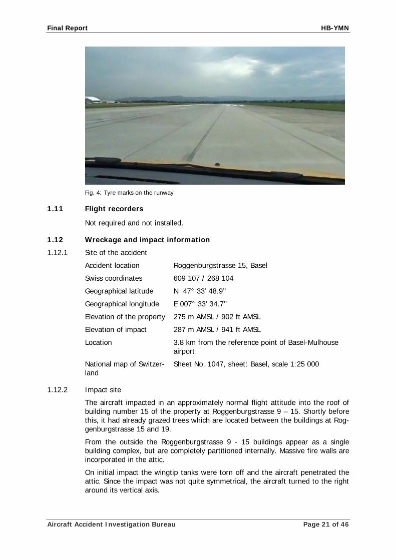
1.10.4 Marks on the runway
During a runway inspection after the accident, two continuous black rubber abra-sion marks were found in a zone of approximately 800 m from the runway 16 threshold up to the intersection with runway 26; these were caused by the two main wheels of aircraft HB-YMN.
Aircraft Accident Investigation Bureau Page 20 of 46
Final Report HB-YMN
Fig. 4: Tyre marks on the runway
1.11 Flight recorders
Not required and not installed.
1.12 Wreckage and impact information
1.12.1 Site of the accident
Accident location Roggenburgstrasse 15, Basel
Swiss coordinates 609 107 / 268 104
Geographical latitude N 47° 33’ 48.9’’
Geographical longitude E 007° 33’ 34.7’’
Elevation of the property 275 m AMSL / 902 ft AMSL
Elevation of impact 287 m AMSL / 941 ft AMSL
Location 3.8 km from the reference point of Basel-Mulhouse airport
National map of Switzer-land
Sheet No. 1047, sheet: Basel, scale 1:25 000
1.12.2 Impact site
The aircraft impacted in an approximately normal flight attitude into the roof of building number 15 of the property at Roggenburgstrasse 9 – 15. Shortly before this, it had already grazed trees which are located between the buildings at Rog-genburgstrasse 15 and 19.
From the outside the Roggenburgstrasse 9 - 15 buildings appear as a single building complex, but are completely partitioned internally. Massive fire walls are incorporated in the attic.
On initial impact the wingtip tanks were torn off and the aircraft penetrated the attic. Since the impact was not quite symmetrical, the aircraft turned to the right around its vertical axis.
Aircraft Accident Investigation Bureau Page 21 of 46

Final Report HB-YMN
Fig. 5: Point of impact on the north-west side of the building at Roggenburgstrasse 15
The aircraft disintegrated on the fire wall between Roggenburgstrasse 15 and 13. The left wing and the left landing gear remained on the roof in the vicinity of the building at Roggenburgstrasse 11. The right wing and the right landing gear were also separated and were flung onto Roggenburgstrasse below. They came to rest in the vicinity of the entrance to the building at Roggenburgstrasse 9. The engine, propeller and cockpit equipment remained in the attic of Roggen-burgstrasse 13 and were completely consumed by fire. The pilot as well as parts of the fuselage and the auxiliary tanks were hurled into an area adjacent to the property at Roggenburgstrasse 9 – 15, where a Robinson children’s playground was located.
1.12.3 Wreckage The following individual observations were made on the wreckage: The left landing gear and the left wing were to a large extent destroyed by the fire. The right landing gear, apart from the missing wheel cowling, was largely preserved. The right tyre was scorched.
Fig. 6: Scorched tyre of the right wheel
Aircraft Accident Investigation Bureau Page 22 of 46

Final Report HB-YMN
The engine and the propeller hub were examined. The other parts found in the attic were so badly damaged by the intense heat that they could not be further examined.
After the wreckage had been recovered, further investigations were carried out on the parts of the wreckage (see section 1.16).
1.13 Medical and pathological information An autopsy of the pilot was performed. Death occurred immediately after impact as a result of the internal injuries suffered from the deceleration forces. No rele-vant pre-existing changes in organs were found which might have adversely af-fected the pilot in his control of the aircraft.
The toxicological investigation found no traces of alcohol, psychoactive drugs or narcotic substances.
1.14 Fire The aircraft caught fire on impact and was completely consumed by fire.
The large amount of fuel on board was dispersed on impact and acted as an ac-celerant for the fire. As a result, the attic of the Roggenburgstrasse 9 – 15 build-ing and the climbing tower of the neighbouring children’s playground were im-mediately set ablaze.
The professional fire brigade of the city of Basel were alerted by the police and immediately began to fight the fire and to evacuate the entire building complex. They were supported by the Allschwil (BL) fire brigade and company fire brigade specialised in fighting chemical fires.
It was possible to extinguish the fire at 12:30.
Fig. 7: Attic of the property at Roggenburgstrasse 9 – 15 on fire
Fig. 8: Burnt-out climbing frame in
the adjacent playground
Aircraft Accident Investigation Bureau Page 23 of 46
Final Report HB-YMN
1.15 Survival aspects
1.15.1 General
The accident was not survivable.
1.15.2 Emergency transmitter
The aircraft was equipped with an emergency transmitter (emergency location beacon aircraft – ELBA). The device was installed and destroyed by the impact. No distress signals were received.
1.16 Tests and research
1.16.1 Examination of the engine
The engine was severely damaged by the fire at the site of the accident. For in-stance, the oil sump had melted away and only the copper conductors remained of all the electrical cables.
The remaining vestiges were inspected visually and no indications of any pre-existing defects could be found. In particular, it was found that: • all spark plugs had a normal appearance, • all combustion chambers and piston domes were of normal coloration, • all cylinders, pistons and piston rings exhibited normal indications of metal-
lic contact and showed no signs of pitting or scoring, • it was possible to move all connecting-rod bearings and gudgeon pins
which did not indicate excessive clearance or other anomalies, • all inlet and exhaust valves were externally undamaged and exhibited no
nicks.
The findings relating to the engine provided no indication of any technical limita-tion on engine power.
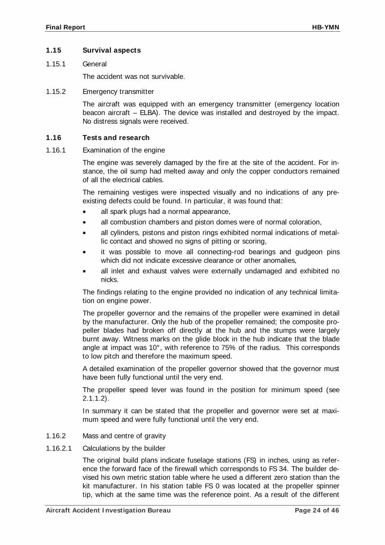
The propeller governor and the remains of the propeller were examined in detail by the manufacturer. Only the hub of the propeller remained; the composite pro-peller blades had broken off directly at the hub and the stumps were largely burnt away. Witness marks on the glide block in the hub indicate that the blade angle at impact was 10°, with reference to 75% of the radius. This corresponds to low pitch and therefore the maximum speed.
A detailed examination of the propeller governor showed that the governor must have been fully functional until the very end.
The propeller speed lever was found in the position for minimum speed (see 2.1.1.2).
In summary it can be stated that the propeller and governor were set at maxi-mum speed and were fully functional until the very end.
1.16.2 Mass and centre of gravity
1.16.2.1 Calculations by the builder
The original build plans indicate fuselage stations (FS) in inches, using as refer-ence the forward face of the firewall which corresponds to FS 34. The builder de-vised his own metric station table where he used a different zero station than the kit manufacturer. In his station table FS 0 was located at the propeller spinner tip, which at the same time was the reference point. As a result of the different
Aircraft Accident Investigation Bureau Page 24 of 46

Final Report HB-YMN
location of the zero station points, it was not possible to convert by simple multi-plication between the two reference systems.
The builder probably used MAC in his calculations because this term was com-monly used in the operation of the aircraft types he had flown and provided him clear information regarding the stability.
Using a spreadsheet software application, the builder had programmed a tool to calculate the mass and centre of gravity position of the aircraft. However, an in-correct wing chord value was used to convert the centre of gravity position to % MAC, resulting in 100% MAC located about 70 cm aft of the wing trailing edge.
Fig. 9: Comparison of Fuselage Station Data
Based on this erroneous data, the pilot calculated a centre of gravity location for the flight in overweight-condition of 22% MAC. His results expressed in % MAC were erroneous. His calculations in centimetres however were correct. According to his spreadsheet, he expected a take-off mass of 2431.7 kg.
1.16.2.2 Calculation after the accident
Based on the available data after the accident, a take-off mass of 2621 kg was calculated. The centre of gravity was 291.5 cm aft of the reference point (propel-ler spinner tip) and the “zero wing fuel weight” (total mass without fuel in the wings and tip tanks) was 1992 kg.
Aircraft Accident Investigation Bureau Page 25 of 46

Final Report HB-YMN
Mass and Balance sheet HB-YMN, calculated for takeoff in Basel on 23.07.2007, for the Flight to Oshkosh WI USA Mass Arm
Empty mass Version E20-VL as per weighing protocol dated 24.05.2007 1'134.5 kg . 267.3 cm
Fuel in Wings and Tip Tanks 885.4 l 628.6 kg 285.5 cm
Fuselage Tanks and Fuel 798 l 631.5 kg 346.1 cm
Lead Ballast under Cockpit Carpet 50.0 kg 170.0 cm
less taxi fuel -8.0 kg 285.5 cm
Pilot 105.0 kg 270.2 cm
Survival and nav kit, tools, pers. effects, catering, baggage 60.8 kg 351.8 cm
Total mass and arm, A/C in T/O position. Kit Designers Limits: arm = 264.4 cm to 290.5 cm @ mass at 1'633 kg (3'600 lbs)
2'602 kg actual
291.0 cm actual
Kit Designers Limits: 15.2% to 35.4% MAC @ 1'633 kg 35.8% MAC
actual Kit Designers max. Zero Wing Fuel Weight: 1'534 kg (AFM)
1'970 kg actual
Notes: 1: Fuel including non-useable fuel
2: Specific gravity = 0.71 for AVGAS
3: For detailed calculation see annex 1
1.16.3 Examination of the right main landing gear tyre
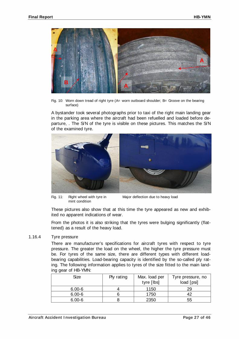
The scorched remains of the right tyre were examined by the tyre manufacturer at his facilities. The tyres, manufactured by Michelin, dimension 6.00-6 AIR, P/N 070-317-0, S/N 6146W00136, exhibited wear of approximately 80% at the shoulder on the outside (i.e. on the right), but only approximately 14% on the inside. On the outside of the centre rib, the rubber had been abraded by friction over the entire circumference. A small superficial cut was also found on the out-board shoulder of the tyre, though it did not extend to the reinforcement.
No further damage or witness marks of any kind were found on the tyre or the tube which would indicate for instance overheating of the tyre due to excessive fulling (marbling).
The rim, the brake and the wheel bearings of the right Gear were examined. All parts were in almost factory new condition.
Aircraft Accident Investigation Bureau Page 26 of 46
Final Report HB-YMN
Aircraft Accident Investigation Bureau Page 27 of 46
A
A
Fig. 10: Worn down tread of right tyre (A= worn outboard shoulder; B= Groove on the bearing surface)
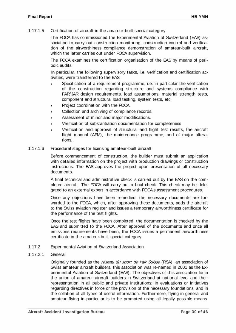
A bystander took several photographs prior to taxi of the right main landing gear in the parking area where the aircraft had been refuelled and loaded before de-parture, . The S/N of the tyre is visible on these pictures. This matches the S/N of the examined tyre.
Fig. 11: Right wheel with tyre in Major deflection due to heavy load
mint condition
These pictures also show that at this time the tyre appeared as new and exhib-ited no apparent indications of wear.
From the photos it is also striking that the tyres were bulging significantly (flat-tened) as a result of the heavy load.
1.16.4 Tyre pressure There are manufacturer’s specifications for aircraft tyres with respect to tyre pressure. The greater the load on the wheel, the higher the tyre pressure must be. For tyres of the same size, there are different types with different load-bearing capabilities. Load-bearing capacity is identified by the so-called ply rat-ing. The following information applies to tyres of the size fitted to the main land-ing gear of HB-YMN:
Size Ply rating Max. load per tyre [lbs]
Tyre pressure, no load [psi]
6.00-6 4 1150 29 6.00-6 6 1750 42 6.00-6 8 2350 55
A
B

Final Report HB-YMN
The airplane flight manual (AFM) for the aircraft contains the following informa-tion on tyres and tyre pressure:
Section 2.16 Limitation placards: Placard: 42PSI/2.9 BAR <1700 KG >55 PSI/3.8 BARR Location: Main wheels near valve stem, valid for 6.00 x 6 / 8 PLY tires
Section 4.4 Pre-flight Walk-Around: Item 7.e. and 11.b.: Tire Condition, Inflation and Wear Up to MTOW 1700 kg Inflate to 42 PSI / 2.9 bar
Section 7.5.1 Main Gear: “Each main gear wheel has a 15 x 6.00 x 6 tire / 8 plies with inner tube in-stalled.”
From the mass and centre of gravity calculations, it is shown (see 1.16.4) that the take-off mass was 2602 kg and the centre of gravity was 291 cm aft of the reference point. The axle of the main landing gear was 294.5 cm aft of the refer-ence point. Thus the load per wheel of the main gear was 1310 kg or 2888 lbs respectively.
The maximum permitted wheel load for the tyres used would have been 2350 lbs according to the above-referenced manufacturer’s information, at a pressure (with no load) of 55 psi, corresponding to 3.8 bar.
There are no indications which would allow any inference concerning the tyre pressure or a pressure check before the accident. Post-crash determination of the actual tyre pressure was not possible because of the destruction of the wheels.
1.16.5 Flaps
The video recordings show that the flaps were retracted during the take-off roll.
The burnt flap actuator motor was found in the debris of the wreckage. Its posi-tion corresponded to the position for retracted flaps.
1.17 Information on various organisations and their management
1.17.1 Federal Office of Civil Aviation
1.17.1.1 General
In Switzerland, as in most states, aviation laws and directives are based on the standards and recommendations of the International Civil Aviation Organisation (ICAO) and on multi-national directives such as the joint aviation requirements (JAR).
According to the Air Navigation Act, the Federal Council exercises supervision over aviation throughout the Swiss Confederation. Direct supervision of civil avia-tion is the responsibility of the Federal Office of Civil Aviation (FOCA), which is an office of the Federal Department of the Environment, Transport, Energy and Communications (DETEC).
Aircraft Accident Investigation Bureau Page 28 of 46

Final Report HB-YMN
Aircraft Accident Investigation Bureau Page 29 of 46
1.17.1.2 Structure
At the time of the accident, the Federal Office of Civil Aviation had approximately 230 employees. At the beginning of 2005, a new organisation was set up in which, in addition to the Aviation Policy Division, three divisions pertain to civil aviation safety (Aircraft, Flight Operations and Infrastructure).
The Aircraft Safety Division monitors the airworthiness of aircraft, manufacturers’ operations and development operations as well as the maintenance undertak-ings, including training and qualification of technical personnel. Within these ar-eas, the department ensures that both national and international safety directives are implemented in the Swiss aviation industry.
The Aircraft Safety Division consists of the following sections: standardisation, enforcement and registers, design and production, maintenance organisations and personnel, aircraft airworthiness and operator airworthiness organisation.
The design and production section is responsible on the one hand for type certifi-cation of aircraft and their components and individual items of equipment. On the other hand, it is responsible for licensing and supervision of design and produc-tion organisations in Switzerland. Its tasks also include the publication of FOCA and other national aviation authorities’ airworthiness directives with corrective di-rectives to the owners of aircraft, in the interest of maintaining airworthiness.
Various tasks are delegated by the FOCA to external organisations.
1.17.1.3 Aircraft in the amateur-built special category
Aircraft in the amateur-built special category, also known as home-built or ex-perimental aircraft, are non-type-certificated aircraft, which as a rule are self-built by the builder(s) in Switzerland and in Liechtenstein. The builder of such an aircraft must provide evidence that he himself has performed 51% of the work, i.e. manufacture or assembly of the components. The builder must confirm that the material used and the construction comply with the production documenta-tion. Any deviations from the production documents must be listed and justified.
1.17.1.4 Airworthiness requirements for aircraft in the amateur-built special category
The airworthiness requirements for aircraft in the amateur-built special category are defined in an agreement between the FOCA and the Experimental Aviation of Switzerland (EAS) association. Requirements based on FAR1/JAR Part 23 or JAR-VLA2 were to be applied to the present type. It is furthermore defined that the maximum take-off mass (MTOM) of an aircraft is limited to 1750 kg, in order for it to be classified as an amateur-built aircraft. A decision on the admissibility of deviations from these requirements is made on a case-by-case basis by the FOCA in consultation with the EAS.
According to the agreement between the FOCA and the EAS, flight testing must be performed on the basis of advisory circular (AC) 23-8A flight test guide of the US Federal Aviation Administration (FAA). However, this AC has been superseded since 14 August 2003 by AC 23-8B flight test guide for certification of part 23 airplanes.
1 FAR – Federal Aviation Regulations: rules and regulations of the American national aviation authority, the
Federal Aviation Administration (FAA). 2 JAR-VLA – Joint Aviation Requirements-very light aircraft: design regulations based on the supranational
European aviation requirements.
Final Report HB-YMN
1.17.1.5 Certification of aircraft in the amateur-built special category
The FOCA has commissioned the Experimental Aviation of Switzerland (EAS) as-sociation to carry out construction monitoring, construction control and verifica-tion of the airworthiness compliance demonstration of amateur-built aircraft, which the latter carries out under FOCA supervision.
The FOCA examines the certification organisation of the EAS by means of peri-odic audits.
In particular, the following supervisory tasks, i.e. verification and certification ac-tivities, were transferred to the EAS: • Specification of a requirement programme, i.e. in particular the verification
of the construction regarding structure and systems compliance with FAR/JAR design requirements, load assumptions, material strength tests, component and structural load testing, system tests, etc.
• Project coordination with the FOCA. • Collection and archiving of compliance records. • Assessment of minor and major modifications. • Verification of substantiation documentation for completeness • Verification and approval of structural and flight test results, the aircraft
flight manual (AFM), the maintenance programme, and of major altera-tions.
1.17.1.6 Procedural stages for licensing amateur-built aircraft
Before commencement of construction, the builder must submit an application with detailed information on the project with production drawings or construction instructions. The EAS approves the project upon presentation of all necessary documents.
A final technical and administrative check is carried out by the EAS on the com-pleted aircraft. The FOCA will carry out a final check. This check may be dele-gated to an external expert in accordance with FOCA’s assessment procedures.
Once any objections have been remedied, the necessary documents are for-warded to the FOCA, which, after approving these documents, adds the aircraft to the Swiss aviation register and issues a temporary airworthiness certificate for the performance of the test flights.
Once the test flights have been completed, the documentation is checked by the EAS and submitted to the FOCA. After approval of the documents and once all emissions requirements have been, the FOCA issues a permanent airworthiness certificate in the amateur-built special category.
1.17.2 Experimental Aviation of Switzerland Association
1.17.2.1 General
Originally founded as the réseau du sport de l’air Suisse (RSA), an association of Swiss amateur aircraft builders, this association was re-named in 2001 as the Ex-perimental Aviation of Switzerland (EAS). The objectives of this association lie in the union of amateur aircraft builders in Switzerland at national level and their representation in all public and private institutions; in evaluations or initiatives regarding directives in force or the provision of the necessary foundations, and in the collation of all types of useful information. Furthermore, flying in general and amateur flying in particular is to be promoted using all legally possible means.
Aircraft Accident Investigation Bureau Page 30 of 46

Final Report HB-YMN
Within its ranks, the EAS manages and organises a technical commission which is open to all interested directly or indirectly in aircraft construction and in amateur flying in general.
1.17.2.2 Tasks of different sections of the association
In this accident, the following sections of the association and their tasks are sig-nificant: • The Technical Commission • The Certification Office
Board Administration
Technical Commission
Certification Office
Regional Directors Engineering Construction
Advisors
Continuing Airworthiness
Reviews
Weight & Balance
Flight Testing
Noise Measurement
Fig. 12: Organisation chart of the Technical Commission
1.17.2.2.1 The Technical Commission of the EAS
The Technical Commission is a supervisory and consultative body. Under it are other technical groups. The EAS Board nominates the heads of the technical groups.
• On the basis of his construction experience, the Construction Advisor ad-vises the builder on completing his project. He monitors construction, load testing and, if necessary weighing and static thrust measurement. The Construction Advisor checks and assesses construction before structural components are sealed. He accompanies and monitors the project up to the EAS final inspection.
• The Construction Inspector carries out the internal EAS final inspection in accordance with the instructions of the Chief Construction Advisor. The Construction Inspector can never be the Construction Advisor on the same project.
• On the basis of his own flying experience, the Flight Testing Advisor ad-vises the builder on the preparation and completion of the test flights. He monitors the flight tests in accordance with the instructions of the Chief Flight Testing Advisor.
• Normally, the builder is test pilot. After consultation with the test flight con-sultant or on instructions from the head of test flights, this activity may be transferred to another suitable test pilot.
• The Engineering Group inspects the aircraft on the basis of the applicable airworthiness requirements. It also checks the completeness and correct-ness of the compliance documentation provided by the builder as well as the necessary supporting data in case of construction modifications or con-struction deviations. The assessment is split into the areas of structure and systems. If the builder requests the EAS Engineer to perform calculations then this takes place under a direct agreement between the builder and the Engineer. Such calculations must then be checked by an engineer who is
Aircraft Accident Investigation Bureau Page 31 of 46

Final Report HB-YMN
not involved in the project. The head of the technical Engineering Group is responsible for coordination or delegation of tasks and for the technical competence of members of the Group.
1.17.2.2.2 Certification Office
The Certification Office (CO), as a unit independent of the Technical Team, re-ports directly to the president of the EAS and constitutes the direct link to the FOCA concerning licensing. To perform this task, it makes use of the resources of the Technical Commission. Specifically, the Certification Office has the following duties:
• Deciding on the acceptance of projects to be built and any necessary clari-fications.
• Deciding on new applications, repair and modification requests.
• Specification of production and test method requirements.
• Checking the completeness and correctness of the compliance documenta-tion already checked by the EAS Engineering Group and verifying that the applicable requirements are fulfilled and that there are no deficiencies which may affect safety.
• Upon successful assessment, issuing of a design conformity for the atten-tion of the FOCA.
• Applying to the FOCA for the issuance of airworthiness certificates.
1.17.2.3 Directives regarding test flights
According to the agreement between the FOCA and the EAS on the airworthiness requirements for aircraft in the self-build special category, flight testing must be performed on the basis of Advisory Circular (AC) 23-8A flight test guide of the US Federal Aviation Administration (FAA); however, this AC has been superseded by the FAA on 14 August 2003 by the issue 8B. EAS sticks to the earlier issue 8A.
AC No. 90-89A “Amateur-built aircraft and ultralight flight testing handbook” of the FAA is made available on the EAS website. With regard to the flight testing document states, that for the testing of a amateur-built or ultralight aircraft, a flight programme off at least 35 flying hours has to be carried out.
1.18 Additional information
1.18.1 General
The information below relates only to the accident relevant parts of the certifica-tion in relation to take-off mass and the corresponding aircraft performance.
1.18.2 Specification of the maximum permitted take-off mass
The application to the EAS of the HB-YMN project dated 3 April 2001 envisaged a maximum take-off mass (MTOM) of 1451 kg. This corresponded to the kit manu-facturer’s data published at that time. On 11 August 2002, the kit manufacturer published a specification in which the MTOM was given as 1542 kg. The applica-tion of the project was amended accordingly.
In the builder’s calculations, an MTOM of 1700 kg appeared after 2006. No change to the project notification is documented.
Aircraft Accident Investigation Bureau Page 32 of 46

Final Report HB-YMN
A larger quantity of fuel was needed for making certain planned record-attempt flights within the “Polar Frontier” project than was available in the existing tanks. Additional installable tanks were therefore envisaged in the wings, fuselage and cabin. This modification would have made possible a MTOM considerably in ex-cess of 1700 kg.
In order to be able to take off with the larger quantity of fuel, the builder in-tended to obtain an approval which would permit him to fly in an “overweight condition” under certain circumstances and subject to conditions.
According to article 2.1 of Annex 2 to the FOCA/EAS agreement on the certifica-tion of amateur-built aircraft, in the present case the EAS Certification Office was responsible only for the airworthiness certificate for the MTOM of 1700 kg. The builder therefore contacted the FOCA and on 8 September 2006 presented his project there in the presence of EAS representatives. During this presentation, the builder presented his request for overweight operation. However, the request was made without specifying the extent to which the MTOM was to be exceeded.
1.18.3 Certification process for MTOM of 1700 kg
1.18.3.1 Activity of the different bodies
• EAS Technical Commission
In December 2006 the head of the Technical Commission was fatally injured in an aircraft accident. At the time of the accident this position was held interim by the president of the EAS. The extent to which the latter was able to perform this role with regard to supervision and advising of the technical groups reporting to him is not known.
• Chief Flight Testing Advisor
The Chief Flight Testing Advisor designated a Flight Testing Advisor for the pro-ject. In the assessment of the Chief Flight Testing Advisor, both the pilot and his Flight Testing Advisor were well qualified for the task.
During the certification for an MTOM of 1700 kg which was within the responsi-bility of the EAS, communication increasingly occurred directly between the builder and the FOCA, especially with regards to the requested IFR certification. The Flight Testing Advisor was only provided with flight testing forms informally via email.
In the course of the investigation he responded to the question “What important issues are concerning you in the aftermath to the accident to HB-YMN?” with: “The absence of a declaration of transfer of responsibility between the EAS and the FOCA. The Flight Testing Advisor was no longer relevant from the moment of the take-over by the FOCA of the certification efforts… … On the basis of the CC e-mails sent to me supported my assumption that the responsibilities rested en-tirely with the FOCA.”
• Test pilot
In this case the test pilot was the builder. He was qualified for the test flights and acquainted with the flight testing procedures. Aircraft HB-YMN was his second self-built aircraft.
Aircraft Accident Investigation Bureau Page 33 of 46
Final Report HB-YMN
• EAS Engineering
The calculations and necessary engineering reports (performance, engine mount, landing gear, wings and horizontal stabilizer) for a 1700 kg MTOM were produced in accordance with the EAS procedures. The mass and balance calculations were performed by the builder himself. The engineering reports were checked by the Certification Office in accordance with independent double verification principles.
• Certification Office (CO) The CO had received neither feedbacks on the flight testing nor the necessary compliance documentation for the limitations in the design summary. From the CO’s point of view, the flight test phase could not yet have been completed at the time of the accident. According to statements from the CO, the builder occasionally doubted the ne-cessity of the processes established by the EAS and expressed this accordingly.
1.18.3.2 Information on flight testing and performance determinations The following areas were tested and documented on the occasion of the flight tests:
1.18.3.2.1 Static position error
On 1 July 2007, three low-altitude level passes were flown over Grenchen aero-drome. Despite the rudimentary arrangements (no measurement grid, turbulent atmosphere, low number of fly-bys), it can be assumed that the results were of acceptable accuracy. The position error was determined to be small. Since posi-tion error is also of relevance for the accuracy of the speed indication it can be concluded that the speed indication was also acceptably accurate.
1.18.3.2.2 Take-off performance
On 1 July 2007, five take-offs were carried out to determine the take-off per-formance.
Only the three shortest take-off rolls were used for the calculation of an average value. According to the test report, the two other measurements were “dis-carded for analysis”, although one of the other two take-off rolls was 620 m which is 35% longer than the aver rage of the three shortest rolls.
For all five trials the forms showed the same take-off mass of 1660 kg, which does not permit an accurate analysis, as fuel consumption was ignored. The rota-tion speed was noted as 63 kt and the intended climb speed to clear the 50 ft obstacle was set at 75 KIAS.
1.18.3.2.3 Climb performance
All tests were performed with a take-off mass of 1700 kg and a centre of gravity noted as “middle” position. All climbs were also carried out with an engine speed of 2500 rpm. The first six climbs were carried out on 3 July 2007. They were executed at speeds between 75 KIAS and 120 KIAS and were used to determine the speeds for best angle of climb (Vx) and best rate of climb (Vy).
On 06 July 2007, a climb was carried out at the speed for the best rate of climb (Vy) of 87 KIAS, the results of which were then used as a reference for the flown climb performance. The atmospheric conditions were approximately ISA+8°. The determined rate of climb between 2000 ft AMSL and 5000 AMSL was approxi-mately 700 ft/min.
Aircraft Accident Investigation Bureau Page 34 of 46

Final Report HB-YMN
1.18.4 Certification Process for MTOM of above 1700 kg
During the presentation on 8 September 2006 at the FOCA, which was attended by EAS representatives, the pilot explained that it will be necessary to exceed the maximum take-off mass of 1700 kg for some of the planned flights. At the end of his presentation, he requested that the Express 2000 ER, HB-YMN, will be certi-fied for temporary operation in overweight condition for the Zurich - Oshkosh verification flight as well as for the planned record flights.
Following the presentation, the builder summarized the decisions of the meeting in minutes which he sent to the FOCA. In this document the pilot stipulated that the FOCA accepts operation with full tanks and full tip- and ferry tanks, and the resulting excessive weight, for the verification flight Zurich - Oshkosh as well as for the planned record flights. This part of the minutes was accepted like this by the FOCA. However, at that time the amount of exceedance had never been quantified.
These minutes have been completed by the FOCA with the discussed certification procedures. Afterwards the minutes were signed by the FOCA, the EAS and the builder.
The FOCA defined structural requirements for the installation of the tip tanks and the auxiliary tanks in the fuselage. Compliance with these was verified during the acceptance inspection.
On 20 July 2007 the FOCA approved the AFM Supplement in which the builder defined a MTOM of 2475 kg. This is the only official document which contains this value of the increased MTOM.
1.18.4.1 Information on flight testing and performance determination
The FOCA made no further requirements for testing the aircraft in the “over-weight condition”. Only a calculated substantiation for the predicted flight per-formance was required.
There is no indication that the aircraft had ever been operated with a mass above 1700 kg.
The performance calculations and the computational assessment of aerodynamic stability were checked by a qualified acquaintance of the head of Engineering. Various methodologies were chosen for this process.
1.18.4.2 Take-off performance
The predicted take-off performance for the planned take-off mass (TOM) of 2475 kg was calculated by the EAS head of Engineering. The performance calculations were based on the results of the flight tests with an MTOM of 1700 kg.
The take-off roll to lift-off was calculated to be approximately 900 m. The head of Engineering stated that he had provided this information to the builder and had expressly instructed him: “If you’re not in the air after 1500 m, abort the take-off!”
1.18.4.3 Climb performance
The calculations showed that the aircraft would be able to lift off at approxi-mately 95 KIAS and would then climb at this speed at a rate of 450 ft/min.
The expected excess power, according to the calculations, would have allowed the aircraft to accelerate horizontally and to achieve a speeds range with even better climb performance (Vy at 2475 kg: 116 KIAS).
Aircraft Accident Investigation Bureau Page 35 of 46
Final Report HB-YMN
The calculated excess power also shows that continuing the flight with an in-crease in energy would have been possible only above a speed of 80 KIAS.
1.19 Useful or effective investigation techniques
1.19.1 Analysis of engine speed during take-off
Among other things, the aircraft’s take-off roll was documented by a number of video recordings. The take-off roll over the first approximately 700 m can be seen on one of these video recordings. The engine noise of the passing aircraft was also recorded. From this sound recording the audio spectrum at the moment when the aircraft passed the camera location was analysed. The propeller speed during the take-off roll could be established in this way. The result gives a pro-peller speed of 2680 rpm.
1.19.2 Analysis of the aircraft speed based on video recordings
On the video recordings it was possible to determine points along the aircraft’s path from clearly identifiable features, such as buildings in the background for example. The time which it took the aircraft to travel from one identifiable point to another identifiable point could be determined. The distance between these points was established with plans and maps. The average speed of the aircraft on such a section could therefore be approximated.
Aircraft Accident Investigation Bureau Page 36 of 46
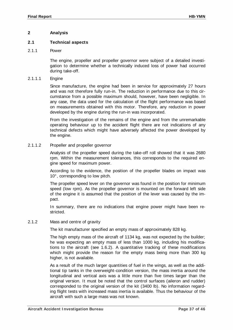
Final Report HB-YMN
2 Analysis
2.1 Technical aspects
2.1.1 Power
The engine, propeller and propeller governor were subject of a detailed investi-gation to determine whether a technically induced loss of power had occurred during take-off.
2.1.1.1 Engine
Since manufacture, the engine had been in service for approximately 27 hours and was not therefore fully run-in. The reduction in performance due to this cir-cumstance from a possible maximum should, however, have been negligible. In any case, the data used for the calculation of the flight performance was based on measurements obtained with this motor. Therefore, any reduction in power developed by the engine during the run-in was incorporated.
From the investigation of the remains of the engine and from the unremarkable operating behaviour up to the accident flight there are not indications of any technical defects which might have adversely affected the power developed by the engine.
2.1.1.2 Propeller and propeller governor
Analysis of the propeller speed during the take-off roll showed that it was 2680 rpm. Within the measurement tolerances, this corresponds to the required en-gine speed for maximum power.
According to the evidence, the position of the propeller blades on impact was 10°, corresponding to low pitch.
The propeller speed lever on the governor was found in the position for minimum speed (low rpm). As the propeller governor is mounted on the forward left side of the engine it is assumed that the position of the lever was caused by the im-pact.
In summary, there are no indications that engine power might have been re-stricted.
2.1.2 Mass and centre of gravity
The kit manufacturer specified an empty mass of approximately 828 kg.
The high empty mass of the aircraft of 1134 kg, was not expected by the builder; he was expecting an empty mass of less than 1000 kg, including his modifica-tions to the aircraft (see 1.6.2). A quantitative tracking of these modifications which might provide the reason for the empty mass being more than 300 kg higher, is not available.
As a result of the much larger quantities of fuel in the wings, as well as the addi-tional tip tanks in the overweight-condition version, the mass inertia around the longitudinal and vertical axis was a little more than five times larger than the original version. It must be noted that the control surfaces (aileron and rudder) corresponded to the original version of the kit (3400 lb). No information regard-ing flight tests with increased mass inertia is available. Thus the behaviour of the aircraft with such a large mass was not known.
Aircraft Accident Investigation Bureau Page 37 of 46

Final Report HB-YMN
As a result of the error in the conversion of the fuselage stations, the pilot’s cal-culation resulted in a centre of gravity position of 22% MAC for the flight in overweight condition. This result gave him the false impression of a centre of gravity in the forward chord quarter. Correctly calculated, however, the centre of gravity would have been at 35% MAC, and with the actual load even at 35.8% MAC, i.e. in the second quarter of the chord.
The pilot’s mass calculation was overly optimistic. In particular, the additional survival equipment, the tools carried and the luggage had only partly or not been considered or its mass had been underestimated, and the approximately 50 kg of lead ballast placed in the cockpit at the last minute were not included in the cal-culation at all. The pilot’s calculation had resulted in a take-off mass of 2474 kg. These calculations never included the complete filling of all fuel tanks. The actual mass at the beginning of the take-off roll, however, was 2602 kg, some 130 kg more that the pilot had calculated. The maximum take-off mass in “overweight condition” according to the AFM supplement was 2475 kg.
2.1.3 Take-off roll
A video recording of the first phase of the take-off roll shows that after rolling for approximately 700 m the aircraft had attained a ground speed of approximately 70 kt. From about this point, smoke was also observed from both wheel fairings. As the take-off roll progressed, there was only a slight increase in speed; the av-erage speed between 700 and 1100 m roll distance was 74 kt. The take-off roll distance to lift-off was 3.4 km. This take-off roll distance is over 3 times as long as the previously calculated distance of 900 m. Such a massive deviation from the calculation cannot be explained solely by inaccuracies of the basic data and any deficiencies in modelling. Rather, it is an indication that there were other fac-tors which had not been foreseen..
From the sequence of the initial acceleration which for the first 700 m agreed with the predictions, but which subsequently decreased, it can be concluded that after some time the rolling resistance must have increased.
The examination of the right main landing gear tyre shows that it was badly worn during the take-off roll. This and the observed smoke permit the conclu-sion, that the tyres have chafed against the wheel fairing. As the pictures show, the tyre was heavily deformed (flattened) under the load, because the pressure was not commensurate with the load on the wheel. It is possible that a wavelike deformation occurred in the tyres due to the extensive flattening. As the rolling speed increased this led to contact of the tyre with the wheel fairing and resulted in a breaking action.
The observed generation of smoke from both wheel fairings, the documented rubber abrasion marks approximately 2.6 km long on the runway, the wear of the bearing surface of the tyre which was found after the accident, and the pro-gress of acceleration, support this hypothesis.
Analysis of the video recordings of the flight in the area of the runway threshold yields a ground speed of approximately 107 kt. Considering the tailwind compo-nent of 5 kt, which was communicated by air traffic control in the take-off clear-ance, the actual air speed was in the region of approximately 102 kt. If one also considers the air density at the time of the accident, the indicated airspeed is around 99 KIAS (see also 1.19.2).
Aircraft Accident Investigation Bureau Page 38 of 46

Final Report HB-YMN
2.1.4 Climb
A continuous climb by an aircraft with constant speed requires the available thrust to be greater than the prevailing drag. This physical law can be applied to surplus of thrust power. In this case one speaks of excess power.
The total drag consists of two different component, the lift-dependent induced drag and the parasite drag. At low airspeeds the induced drag dominates; it may reach very high values in slow flight with a high mass. It reduces exponentially as speed increases.
Parasite drag increases as speed increases. For this reason, as the airspeed of an aircraft increases, the total drag falls from an initially high value before rising again at high speeds.
From this relationship, it is apparent that a very heavily loaded aircraft can only climb within a specific speed range, i.e. in the range where there is excess power available. The mass of the aircraft is of critical importance, because the mass de-termines the required lift and hence, directly, the induced drag. If a given aircraft is more heavily loaded, the minimum speed from which excess power exists in-creases and the amount of excess power is reduced.
The calculations of climb performance for HB-YMN with a take-off mass of 2475 kg were based on environmental condition assumptions that roughly matched those of the day of the accident. They showed that excess power should have been available at a speed above 80 KIAS. The conditions on the day of the acci-dent differed in the following areas from those assumed in the calculation:
• The actual take-off mass was 2602 kg, i.e. about 130 kg more than as-sumed in the calculation.
• The pilot had to maintain a large elevator down deflection due to the cen-tre of gravity being so far aft.
It must further be noted that the calculations were calibrated on flight test data which may be of questionable accuracy (see 1.18.3.2 ff).
It may be concluded that excess thrust required for a climb would only have been available at an airspeed significantly higher than 80 KIAS. The attained speed of nearly 100 KIAS apparently was still insufficient.
The visibly unstable progress of the flight after the extraordinarily long take-off roll indicates that the aircraft’s speed was too low.
The fact that this condition did not change indicates that the aircraft, regarding excess power, was in an indifferent flight condition, i.e. drag and thrust were just balanced. Evidently sufficient excess power was not available. Therefore the pilot was not able to accelerate the aircraft to the range of excess power. As a result, it was not possible to climb and the continuation of the flight was not possible.
Aircraft Accident Investigation Bureau Page 39 of 46
Final Report HB-YMN
Fig. 13: Effect of take-off mass on excess power (qualitative depiction)
Since the aircraft, as explained above, was generally unable to climb it is unlikely that a departure in the opposite direction would have been successful, in spite of the slight headwind.
2.2 Human and operational aspects
2.2.1 Operational aspects
2.2.1.1 Flight performance
The calculated take-off roll distance had been calculated as just over 900 m. The available runway provided large reserves for a controlled extension of the take-off roll phase.
The pilot needed a take-off roll distance of 3.4 km for the take-off. This is over three and a half times longer than expected. The fact that the take-off roll dis-tance was increased by such an amount must have given the pilot a clear indica-tion that the predicted and actual flight performance were very different.
Aircraft Accident Investigation Bureau Page 40 of 46
Final Report HB-YMN
An aborted take-off would have been possible for a very long time, given the long runway and the accompanying fire service vehicle.
After lift-off, the pilot had no choice other than to try to accelerate the aircraft to the point where a climb was possible. This endeavour was futile, because of the above-mentioned parameters. After take-off it was planned to perform a left turn towards the Rhine River before reaching the conurbation. However, flying a turn would have required even additional excess thrust. Therefore, the pilot was forced to fly straight ahead towards the city where a collision with obstacles oc-curred.
2.2.2 Human aspects
2.2.2.1 Pilot
The pilot had already built an amateur-built aircraft and flown numerous record flights in it. In this way he had acquired great experience. He had a very critical to dismissive attitude towards official procedures and restrictions when these im-peded him in achieving his goals.
He had prepared the “Polar Frontier” project with great care over a long period of time and had carried out and documented his work on the aircraft meticu-lously.
This changed noticeably when the begin of the record flights was moved forward by including the flight to Oshkosh into the “Polar Frontier” project. The time for the flight to Oshkosh had to be selected such that it would arrive during the EAA AirVentures. This meeting occurs annually for ten days. Therefore the original, al-ready ambitious schedule could not be maintained and there was insufficient time for the thorough completion of the necessary flight tests and the provision of the required compliance evidence.
Another reason for absolutely having to make the flight within this window of opportunity was the need to find sponsors for the project. The event in Oshkosh provided a unique opportunity to do this. It is understandable that the pilot wished to avail himself of this opportunity. To increase publicity, media represen-tatives were invited to attend the take-off. The presence of the press, the public interest and the intention to find sponsors in Oshkosh might have influenced the pilot to insist on the take-off.
All these factors must have led to a considerable pressure to succeed. It is a well-known phenomenon that under such circumstances a self-dynamics and euphoria develop which may inhibit reasonable thought processes. This process becomes stronger particularly if unexpected circumstances bring the success of the project as a whole into question.
This may explain why the objective reasoning powers of this experienced pilot, who had prepared the planned project very conscientiously for a fairly long pe-riod of time, deserted him in the final phase of flight preparation and actual exe-cution.
The pilot relied solely on a computational flight performance estimation. It is not comprehensible that he commenced the flight with an aircraft mass 50% higher than any for which experience was available.
Aircraft Accident Investigation Bureau Page 41 of 46

Final Report HB-YMN
2.2.2.2 Experimental Aviation of Switzerland
The EAS was charged with monitoring the construction flight testing advising and certification of the EXPRESS 2000 ER aircraft. According to the agreement (Dele-gationsvertrag zwischen EAS und BAZL) with the FOCA, the EAS was responsible for amateur-built aircraft with a maximum take-off mass of up to 1750 kg.
It is evident from the documentation that the procedures which had been defined within EAS had not always been followed. However, this had no direct effect on the course of the accident.
An increase of the MTOM above 1750 kg as well as the IFR certification was not within the responsibility of the EAS anymore. Therefore the builder had to con-tact the FOCA directly.
There was a deviation from the basic principle that the Technical Commission is the single point of contact with the FOCA. This link was now established directly by the “The Polar Frontier” project team and the EAS was less and less involved.
2.2.2.3 Federal Office of Civil Aviation
The FOCA now defined the corresponding requirements for the technical modifi-cations and IFR certification, which involved additional efforts on the part of the builder. He often questioned these requirements and tried to put the FOCA under pressure in this regard. He expressed his opinion that if the project failed, this would be a result of the conduct of the FOCA.
The FOCA yielded partially to this pressure and amended several requirements to be fulfilled several times, or extended deadlines for the submission of compliance evidence to a later date.
For the increase in MTOM, which the builder had not previously specified, only calculations were requested before the corresponding AFM supplement was ap-proved. At no time did the national aviation authority require testing of the air-craft with an increased take-off mass. Particularly for such a significant increase of the originally certified take-off mass, static tests, roll tests and flights with a gradual increase in take-off mass would have been necessary.
Aircraft Accident Investigation Bureau Page 42 of 46

Final Report HB-YMN
3 Conclusions
3.1 Findings
3.1.1 Crew
• The pilot was in possession of the licences necessary for the flight.
• There are no indications of the pilot suffering any health problems immedi-ately before or during the accident flight.
• The pilot was an experienced long-haul pilot and had already set numerous records.
• The pilot was under enormous pressure of time and pressure to perform, as the record flight to Oshkosh could not be postponed.
3.1.2 Technical aspects
• The aircraft was temporarily certified for VFR and IFR operation.
• The aircraft was certified for certain flights in an overweight condition of 2475 kg.
• The mass and centre of gravity of the aircraft were outside the permitted limits at the time of the accident.
• The actual mass at the beginning of the take-off roll was 2602 kg.
• The aircraft was 70% heavier than the original MTOM of the aircraft kit.
• The aircraft was 53% heavier than the mass of 1700 kg, for which corre-sponding structural calculations were carried out and flight tests per-formed.
• The aircraft was 127 kg heavier than the mass of 2475 kg used in the cal-culations for the predicted performance parameters.
• The centre of gravity was at 291.5 cm and therefore 1 cm aft of the per-missible range specified by the manufacturer for the original kit.
• The tyres were significantly flattened prior to take-off due to the heavy loading
• The maximum permissible wheel loading for the tyres used was exceeded during the accident flight
• After the accident, black marks from abraded rubber, approximately 2.6 km in length, were found on runway 16; these originated from the two tyres of the main landing gear.
• The right main landing gear which was recovered after the accident showed significant wear from friction.
• The investigation revealed no indications of any technical faults which could have negatively affected power produced by the engine.
Aircraft Accident Investigation Bureau Page 43 of 46
Final Report HB-YMN
3.1.3 History of the flight
• As it began to taxi, the aircraft was supported at the elevator to prevent the nose wheel from lifting.
• The take-off from the runway in use, runway 16 in Basel-Mulhouse, took place with a 5 kt tailwind.
• After a rolling distance of 700 m, the speed was approximately 70 kt.
• The average take-off roll speed from 700 m to 1100 m was 74 kt.
• Smoke appeared in the area of both main wheels after a take-off roll dis-tance of approximately 800 m.
• Radio communications between the tower, the fire-fighting services vehicle and the pilot took place on the same frequency.
• The tower and the pilot communicated in English.
• The crew of the fire fighting service vehicle observed the smoke develop-ment during the take-off run and reported it twice to the tower in French.
• The TWR acknowledged this message partially in French without repeating it to the pilot.
• The take-off roll was some 3.7 times longer than calculations predicted.
• After a roll distance of approximately 3.4 km, the aircraft lifted off at a ground speed of approximately 107 kt, corresponding to an indicated air-speed of about 99 KIAS.
• After lift-off, the aircraft flew in a high-pitch, unstable flight attitude with the elevator deflected downwards.
• The flaps were retracted.
• After take-off there was no excess power available, so that the aircraft could neither accelerate, climb, nor fly a turn.
• The flight as far as the site of the accident took place at a low height above the ground and without any significant gain in altitude.
3.1.4 General conditions
• For Amateur-built aircraft the maximum take-off mass is 1750 kg.
• The aircraft had never, neither on the ground nor in the air, been operated with a mass of more than 1700 kg.
• There were no tests with a gradually increased take-off mass. None were required by the FOCA.
• The certification for operation in overweight condition with a MTOM of 2475 kg was granted by the competent authority based on calculated take-off and flight performance data.
• Based on the performance calculations at 2475 kg submitted for certifica-tion, the aircraft should have lifted off after a ground roll of 900m at an in-dicated speed of 95 kt, and then climbed at a rate of 450 ft/min.
• The length of runway 16 was 3900 m.
Aircraft Accident Investigation Bureau Page 44 of 46

Final Report HB-YMN
• The aircraft rolled for approximately 50 seconds between the predicted lift-off point and the actual lift-off.
• It was planned that after take-off the pilot would make a left turn towards the Rhine River.
• With the exception of the slight tailwind, the weather conditions had no in-fluence on the accident.
3.2 Causes
The accident is attributable to a collision of the aircraft with obstacles because after lift-off it was not able to accelerate, to climb or to make a turn due to its mass, centre of gravity position and available power.
The following factors contributed to the accident:
• The time pressure and the pressure to succeed which have adversely af-fected the pilot’s judgement.
• Inadequate monitoring and supervision of the responsible authorities dur-ing the testing and certification process.
Aircraft Accident Investigation Bureau Page 45 of 46

Final Report HB-YMN
Aircraft Accident Investigation Bureau Page 46 of 46
4 Safety recommendations and measures taken since the incident
4.1 Safety recommendations
None
4.2 Measures taken since the accident
On 10 September 2007 the FOCA issued a precautionary directive. According to this it is forbidden for experimental aircraft to take off from the national airports on test flights. On the other aerodromes it is forbidden to take off in experimen-tal aircraft on tests flights over densely populated areas. These restrictions also apply to experimental aircraft with special authorisation.
On 07 October 2008 the FOCA issued further measures for experimental aircraft in Switzerland. They concern the certification of aircraft and training at the Ex-perimental Aviation of Switzerland association (EAS).
Due to an increased number of accidents since spring 2007, the FOCA has sub-jected the procedures for certification, scheduled technical inspections and su-pervision in the area of experimental aircraft to a comprehensive review.
The FOCA determined that measures are to be taken in the interest of safety, particularly in the light of recent developments of amateur-built aircraft. Today, some experimentals are equipped with highly advanced cockpit systems and may reach airspeeds in excess of 400 kilometres per hour.
To account for the new situation, the FOCA, in agreement with the EAS, has de-fined the following measures:
• On complex projects, i.e. aircraft which require special authorisation, the FOCA will monitor and coordinate certification more closely.
• For the certification of complex aircraft, the EAS must in the future nomi-nate an overall project manager, who must have a general oversight of all sub-domains (technical and operational aspects). The overall project man-ager acts as the direct contact partner for the FOCA.
• The FOCA is intensifying training of the designated construction and flight test advisors within the EAS.
Payerne, 23 September 2009 Aircraft Accident Investigation Bureau
This report contains the AAIB’s conclusions on the circumstances and causes of the accident which is the subject of the investigation.
In accordance with article 3.1 of the 9th edition of Annex 13, valid from 1 November 2001, of the Con-vention on International Civil Aviation of 7 December 1944 and article 24 of the Federal Air Navigation Act, the sole purpose of the investigation of an aircraft accident or serious incident is to prevent acci-dents or serious incidents. The legal assessment of accident/incident causes and circumstances is expressly no concern of the accident investigation. It is therefore not the purpose of this investigation to determine blame or clarify questions of liability.
If this report is used for purposes other than accident prevention, due consideration shall be given to this circumstance.

Investigation report HB-YMN Annex 1
Aircraft Accident Investigation Bureau Page 1
Supplementary Mass and Balance calculation HB-YMN for Takeoff Basel, 23.07.2007 for Flight to Oshkosh WI USA Mass Arm Moment
Empty mass Version E20-VL as per weighing protocol dated 24.05.2007 1'134.5 kg . 267.3 cm 303'249.80
RH FWD CTR TANK empty mass 5.0 kg 327.4 cm 1'637.00RH AFT CTR TANK empty mass 11.0 kg 415.0 cm 4'565.00LH FWD CTR TANK empty mass 4.8 kg 327.4 cm 1'571.52LH AFT CTR TANK empty mass 9.1 kg 415.0 cm 3'776.50AFT AUX TANK empty mass 22.5 kg 359.1 cm 8'079.75FWD AUX TANK empty mass 15.3 kg 255.0 cm 3'901.50Fuel in Wings and Tip Tanks 885.4 l 628.6 kg 285.5 cm 179'442.43Fuel in RH FWD CTR TANK 28.5 l 20.2 kg 327.4 cm 6'613.48Fuel in RH AFT CTR TANK 86.5 l 61.4 kg 415.0 cm 25'481.00Fuel in LH FWD CTR TANK 28 l 19.9 kg 327.4 cm 6'515.26Fuel in LH AFT CTR TANK 85.5 l 60.7 kg 415.0 cm 25'190.50Fuel in AFT AUX TANK 424 l 301.0 kg 359.1 cm 108'089.10Fuel in FWD AUX TANK 175.6 l 124.7 kg 255.0 cm 31'798.50less Fuel drained before T/O (due to leak) -24.1 kg 359.1 cm -8'654.31Lead Ballast under Cockpit Carpet (last minute change) 50.0 kg 170.0 cm 8'500.00less taxi fuel -8.0 kg 285.5 cm -2'283.60Pilot 105.0 kg 270.2 cm 28'371.00Survival items, immersion protection garment 5.9 kg 270.0 cm 1'593.00Food, drinking water (4 x 1.5l water + 500gr.) 6.5 kg 300.0 cm 1'950.00Navigation Kit 10.0 kg 270.0 cm 2'700.00Personal Effects in Baggage Compt. (J) 5.0 kg 455.0 cm 2'275.00Maintenance Tool Kit + tie down Equipm. 8.4 kg 455.0 cm 3'822.00 Different items as per photos taken prior departure (see note 3)
25.0 kg 362.0 cm 9'050.00
Total mass and arm, A/C in T/O position. Kit Designers Limits: arm = 264.4 cm to 290.5 cm at a mass of 1'633 kg (3'600 lbs)
2'602 kg actual
291.0 cm actual
757'234.43
Kit Designers Limits: 15.2% to 35.4% MAC @ 1'633 kg 35.8% MAC
actual
Kit Designers max. Zero Wing Fuel Weight: 1'534 kg (AFM)
1'970 kg actual
Note 1: Fuel in Tanks includes non usable Fuel
Note 2: Calculated spec. gravity = 0.71 for AVGAS Note 3: Estimation based on photos taken before departure of the baggage below: Black bag on FWD AUX tank A Red suitcase on FWD AUX tank B Olive pouch below red suitcase (with boat?) C Black pouch behind pilot D Container on top of AFT AUX tank, behind pilots head E Brown bag behind LH side window F Red bag in lower part of baggage compartment G Olive pouch in baggage compartment (like sleeping bag) H

Investigation report HB-YMN Annex 1
Aircraft Accident Investigation Bureau Page 2
H
A
B
C
H
D
B
C
EF
J
G
A

Investigation report HB-YMN Annex 2
Aircraft Accident Investigation Bureau Page 1
Presentation of chronological progress of planning, construction and testing