final report - apps.dtic.mil · differences are not well understood, despite prior attempts to...
TRANSCRIPT

Final Report
Period of Performance:
1 October 2003-30 September 2005
Prepared by:
Dr. Ian McNabPrincipal Investigator
Institute for Advanced TechnologyThe University of Texas at Austin
3925 W. Braker Ln., Suite 400Austin, TX 78759
20050815 066Grant #: N00014-04-1-0064Distribution: Electronic and US MailRecipients: S. C. Schreppler, ONR 334
K. Seward, ONR N66018G. Olivas, ONRDTICNRL Code 5227
IAT Report: R 0419 July 2005

REPORT DOCUMENTATION PAGE Form ApprovedOMB NO. 0704-0188
Public reporting burden for this collection of information Is estimated to average 1 hour per response, including the time for reviewing instructions, searching existing data sources, gathering andmaintaining the data needed, and completing and reviewing the collection of information. Send comments regarding this burden estimate or any other aspect of this collection of information,including suggestions for reducing this burden, to Washington Headquarters Services, Directorate for Information Operations and Reports, 1215 Jefferson Davis Highway, Suite 1204, Arlington, VA22202-4302, and to the Office of Management and Budget, Paperwork Reduction Project (0704-0188), Washington, DC 20503.
1. AGENCY USE ONLY (Leave blank) 2. REPORT DATE 3. REPORT TYPE AND DATES COVERED
August 2005 Final Report, 10/01/2003-09/30/2005
4. TITLE AND SUBTITLE 5. FUNDING NUMBERSFinal Report-Homopolar Motor and Brush Development Studies Office of NavalResearch Contract #N0001 4-04-1-0064 Contract # N00014-04-1-0064
6. AUTHOR(S)
I. R. McNab
7. PERFORMING ORGANIZATION NAME(S) AND ADDRESS(ES) 8. PERFORMING ORGANIZATION REPORTInstitute for Advanced Technology NUMBER
The University of Texas at Austin3925 W. Braker Lane, Suite 400 IAT.R 0419
Austin, TX 78759-5316
9. SPONSORING / MONITORING AGENCY NAME(S) AND ADDRESS(ES) 10. SPONSORING / MONITORING AGENCY
Office of Naval Research Regional Office San Diego REPORT NUMBER
4520 Executive Drive Suite 300San Diego, CA 92121-3019
11. SUPPLEMENTARY NOTES
12a. DISTRIBUTION / AVAILABILITY STATEMENT 12b. DISTRIBUTION CODE
Approved for public release; distribution unlimited. A
13. ABSTRACT (Maximum 200 words)
Substantial benefits in ship design and operating economies are expected to accrue to the Navy if electric ship propulsiontechniques can be successfully developed and introduced in the future Navy fleet. One area of interest toward this end isin superconducting homopolar motors. This report surveys prior data, reports, papers, and other studies that relate tosuperconducting homopolar motors. It also includes summaries of discussions held by the author with General Atomics,the Naval Surface Warfare Center, and the Office of Naval Research on the subject.
14. SUBJECT TERMS 15. NUMBER OF PAGES
Homopolar motors, generators, electric ship, brush polarity, superconducting materials, 72unipolar or acyclic machines, metal fiber brushes
16. PRICE CODE
17. SECURITY CLASSIFICATION 18. SECURITY CLASSIFICATION 19. SECURITY CLASSIFICATION 20. LIMITATION OF ABSTRACTOF REPORT OF THIS PAGE OF ABSTRACT
Unclassified Unclassified Unclassified UL
NSN 7540-01-280-5500 Standard Form 298 (Rev.2-89)Prescribed by ANSI Std. 239-18 298-102

FINAL REPORT
Period reported: 1 October 2003 through 30 September 2005
1. Contract Summary
"* Grant number: N00014-04-1-0064"* Period of performance: 1 October 2003 to 30 September 2005"* Total value of awarded Grant: $39,243.00
2. Contract Personnel
The Key Person involved in this effort was Dr. Ian R. McNab, Principal Investigator.Dr. McNab is a Senior Research Scientist at The University of Texas at Austin and Director ofthe Electromagnetic Systems Division (ESD) at the Institute for Advanced Technology (IAT).He has had extensive prior experience and involvement in superconducting homopolargenerators and motors and in the development of fiber and other brushes for these and similarmachines. Toward the latter part of 2004, Dr. Chadee Persad of the IAT became involved inwork to evaluate the debris produced by worn metal fiber brushes. Dr. Persad is also a SeniorResearch Scientist at UT and is the Team Leader on High-Performance Materials at the IAT.
3. Introduction and Future Naval Relevance
Substantial benefits in ship design and operating economies are expected to accrue to theNavy if electric ship propulsion techniques can be successfully developed and introduced in thefuture Navy fleet. Several different concepts have been evaluated over the last few decades. Oneimportant technology that offers significant operating benefits is the use of high temperaturesuperconducting materials. Such materials allow the operating magnetic fields in motors andgenerators to be increased significantly compared with conventional (ferromagnetic or iron-coredtechnology) machines, thereby providing attractive operating system power densities. At thepresent stage of superconductor development, it is easier to envision the use of superconductingtechnology in direct current (DC) machines than in alternating current (AC) machines. Oneimportant class of such DC machines is known as homopolar (sometimes also referred to as"unipolar" or "acyclic") machines. A very important feature of such machines is that all themachine power has to be transferred through a sliding interface comprised of brushes thatoperate on sliprings. Several features are important in achieving an optimum current transfersystem of this type, including:
- the sliding contact must operate stably mechanically, electrically and thermally;- the electrical and frictional losses must be acceptably small;- the wear rate of both the brush and slipring must permit acceptable operating life;- access to the sliprings must be made available for inspection and replacement (if required).
A complicating feature of this type of machine is that the slipring on which the brush slidesmay intersect the magnetic field in such a way that internal circulating currents are created that
IAT.R 0419 1

may adversely affect the brush operation and performance. The adverse effects of this can bealleviated by suitable design of the slipring.
Developments in this area are presently being pursued by General Atomics (GA), aContractor for the Office of Naval Research (ONR), in a program that has led to the design,fabrication and test of a multistage prototypic 3.7 MW superconducting motor that uses metalfiber brushes.
4. Statement of Work
As noted in Section 2 above, the Principal Investigator for this study has had considerableprior experience in the development of current transfer systems of this type. Hence, the objectiveof this study was to transfer this experience to the present ONR and GA project team. TheStatement of Work for this Grant called for:
The Principal Investigator will retrieve prior data, reports, papers and other studies that relateto homopolar machine developments and brushes that may be suitable for use in such machines.In addition, he will visit GA (San Diego) for three meetings with the ONR/GA project team fordiscussions on these topics and the machine testing program. Also, he will visit the NavalSurface Warfare Center in Philadelphia to review testing of the superconducting homopolar testmachine. These discussions will be summarized in written reports and a final report will beprovided at the conclusion of this effort.
5. Technical Report
5.1. Background
The support being provided by the IAT for ONR on this program is focused on the issuesrelating to the brushes being used and developed to transfer the load current to thesuperconducting homopolar motors being developed by General Atomics (GA) for shippropulsion. In common with earlier experience in the brush field, significant polarity differenceshave been observed during brush system tests at GA. The fundamental reasons for these polaritydifferences are not well understood, despite prior attempts to explain the effects. Generally it isfound that the brush having a positive polarity operates with significantly higher voltage dropand wear rate than the brush having a negative polarity. From the GA data, it seems that thenegative brushes will have a lifetime that is acceptable for fleet operation, but the wear rate ofthe positive brushes is questionable and may demand more frequent replacement than can betolerated in fleet operation.
5.2. Integrated Project Team Meetings
Under the auspices of this grant, the IAT has been invited to participate in meetings of theintegrated product team (IPT) set up by the Office of Naval Research (ONR) with GA. Thesemeetings were generally scheduled on a quarterly basis. During this contract period, Dr. McNab,attended the following meetings and provided comments to ONR:
IAT.R 0419 2

Table I. Meeting Attendance
Date Place Meeting type IAT person Report provided
8 Dec 2003 Anteon, Qtrly. Progress Review Dr. McNab See Appendix Al of thisWashington report
19 Feb 2004 Anteon, Workshop on Brushes Dr. McNab See Appendix B andWashington and Brush Holders Appendix G
13-14 Apr 2004 GA, San Diego Qtrly. Progress Review Dr. McNab See Appendix C
20-22 Oct 2004 Anteon, Ballston IPT Meeting #2 Dr. Persad
30 Nov 2004 Anteon, Ballston IPT Meeting #3 Dr. Persad Briefing given on:"Contact MaterialsPerformance" - see
Appendix D
16-17 Dec 2004 GA, San Diego Homopolar Brush Dr. PersadWorkshop
5.3. GA dataDr. McNab has received and reviewed test data and reports provided by GA and Anteon duringthe duration of this effort. Where appropriate, comments have been provided verbally, by emailor in written documents to GA and ONR personnel. In this regard, Dr. McNab signed a GA Non-Disclosure Agreement agreeing to protect the confidentially of the data thus provided.
5.4. Basic Studies on the Oxidation of Copper
During the summer of 2004, Dr. Persad supervised a student, Mr. Eric Bierschenk, whoinvestigated some basic aspects of the oxidation of copper. These studies, which are described inIAT Paper P.0742, were focused on the effects of a marine environment on electric railguncomponents such as copper rails and were not funded under this grant. However, they may alsobe applicable to the copper-fiber brush environment within the GA machines and are thereforeincluded here as Appendix E.
5.5. Early Work on Fiber BrushesThe early work carried out on fiber brushes is summarized here in Appendix F, which should beread in conjunction with the briefing given at the 19 February 2004 meeting (see Appendix G).
6. Expenditures:Monthly financial statements have been provided, and a final invoice will also be provided, asrequired by the contract.
' With the benefit of hindsight, some of the comments in these Appendices have been amended and updated to
improve their relevance.
IAT.R 0419 3

APPENDIX A
Memo to: Ellie Martin (ONR) and Will Creedon (GA)Subject: Comments on the Superconducting Homopolar Motor Quarterly Review No. 8
held at Anteon on 8 December 2003From: Ian R. McNab (UT-IAT)Date: 12 December 2003
1. INTRODUCTIONThank you for inviting me to attend the meeting. It was both very interesting and also
reminiscent of previous projects that I have been associated with, both in the U.K. and U.S.These included early efforts at the IRD Co. Ltd., in Newcastle, England from about 1964 toabout 1972, Westinghouse R& D Center in Pittsburgh, PA from about 1975 to 1982, and passinginvolvement with the NSWC Annapolis superconducting ship propulsion program from the1970's and 80's. While at IRD and Westinghouse I was considerably involved in the currentcollection portion of the programs. This involved the development of brushes that utilized solidmetal-graphite blocks, metal-plated carbon fibers, metal fibers or liquid metal systems.
The discussions were both interesting and well done. There is clearly a concern about theperformance of the HiPerCon brushes, and I have provided more comments below.
2. GENERAL COMMENTSThe essential feature of homopolar machines, in contrast to most other electrical
machines that are commonly encountered, is that ALL of the machine power has to betransferred through the brush or current collection system. This necessarily involves currenttransfer across a sliding interface. The difficulty of doing this successfully for long periods oftime, together with the relatively low voltage and therefore high current requirements of thesemachines, is why early efforts (in the late 19th Century) to use homopolar generators for electricutility systems were displaced by the introduction of the AC machines that we know today,which were developed primarily by Tesla and Westinghouse - in strong competition withThomas Edison.
Nevertheless, the homopolar machine has some features that make it of interest forspecialized applications. One of these is that there is no armature reaction of the applied currenton the field windings (since the forces are orthogonal), which is attractive for a super-conductingcoil system where substantial disturbances to the field winding can cause it to go "normal".Together with the prospect of low electrical and acoustic noise, these are the most likely reasons
2why ONR is considering it today for ship propulsion under the GA Contract. Nevertheless, oneshould not forget this essential brush requirement. In short, designing the machine without beingfully cognizant of this aspect is likely to lead to unrealistic expectations that can be hard toachieve. Often in the past I have seen organizations that have been interested in homopolarmachines fail to appreciate this fact, with the result that disappointments occur as the programprogresses.
I make these comments because I get some sense that this may have already happened onthis program and I want to (a) guard against unrealistic expectations for the program and (b) help
2 1 have not had access to the GA proposal and do not know what advantages or features were claimed in that
proposal. However, the aspects mentioned above have been the most common ones used in the past to support thedevelopment of super-conducting machines for this application.
IAT.R 0419 4

you to understand the difficulties that the brush designers face, so that they can be bettersupported. It is not a feasible approach to "design" a machine on the basis only of the super-conducting magnets and the size and weight constraints demanded by the user, without fullyappreciating the brush system requirements and its operation. Since the brushes are at the heartof the machine operation (and generally, literally, at the heart of the machine structure), the brushdesigners must be given an equal seat at the table when all system aspects of the machine arebeing discussed, and their difficulties have to be appreciated by all concerned.
From the comments I have heard, it appears that the program started without anevaluation of brush system options. That is, the HiPerCon brushes were selected as the preferredbrush supplier from the beginning of the program. Although the little information I have seenabout these brushes is promising, this may or may not have been the correct solution - it is tooearly to tell (at least for me). The fact that the wear of the positive brushes is higher thanexpected (and desired) and that no solution appears to have yet been achieved by HiPerCon isclearly a concern. I have seen no information that indicates that HiPerCon understands this issue,nor have I seen a proposed solution from HiPerCon. (That is not so say that HiPerCon may nothave such understanding or solutions but merely to say that they have not been revealed ordiscussed in my presence.)
3. HISTORICAL PERSPECTIVE ON CURRENT COLLECTIONI don't want to dwell on the past too much but a few comments on the general
development of brushes may be useful in case you are not familiar with the subject - and in viewof the importance for this type of machine. If you are familiar with all of this I apologize.
As a general rule, one has to balance multiple factors in evaluating the performance of thebrush or current collection system. For a solid brush these include:
(i) The electric voltage drop across the interface.This voltage drop multiplied by the current density transferred by the brushdefines the electrical portion of the dissipation at the brush site (Watts/m2).
(ii) The friction coefficient at the sliding interfaceThis friction coefficient multiplied by the sliding speed and the brush pressurenormal to the interface defines the mechanical losses (Watts/m2).
(iii) The brush life(iv) The slipring life(v) Necessary auxiliaries
These might include temperature control, atmosphere control, debris wearmanagement, etc.
The general perversity of life seems to ensure that one cannot easily achieve all of thegoals that one would like to have for all of these parameters. Of course, in many cases what wecan achieve is acceptable - but we always want more! Solid brushes (as used in many everydaydevices) are generally optimized to have a brush operating pressure that provides approximatelyequal electrical and mechanical losses, although the tendency is to operate on the higher pressureside of this optimum because the consequences of too low a brush pressure is lack of a goodcontact and, should this deteriorate into an arcing situation, this is generally more damaging tothe slipring surface than operating with a somewhat higher pressure and accepting higherfrictional losses.
IAT.R 0419 5

3.1. Liquid MetalsThe disk homopolar was the first electrical machine studied by Michael Faraday in the
1830s. He used liquid mercury as the way to make contact with the periphery and the axis of thedisk. Liquid metals of various kinds have been investigated for this purpose until recently,although there are only a limited number of acceptable candidates that are liquid at or near roomtemperature. Broadly speaking, liquid metals have the following characteristics.
a) Liquid mercury has a high density and therefore has high viscous losses which make itgenerally unacceptable for homopolar generators that have relatively high peripheralspeeds. Operating conditions for low speed motors (such as GA and ONR aredeveloping) are easier but the overwhelming opinion these days is that the toxicity ofmercury makes it an unacceptable choice.
b) An attractive choice from the electrical conduction and low density aspect is the alkalimetal sodium and, more commonly, one of the eutectic alloys with potassium, (NaK) thathas a melting temperature below room temperature. Several machines have been builtwith this material, including most recently, the NSWC Annapolis super-conductingmachines. The difficulties with this material are its well-known reactivity with water (andeven humid air) and its tendency to form highly reactive super-oxides that have causedsevere personnel injury on more than one occasion. It is therefore necessary to maintaintight control of the machine environment through careful atmospheric control andmonitoring and it is also necessary to continuously circulate the NaK through some formof filtration and purification system to maintain cleanliness of the liquid.
Given the objective of the ONR/GA program, my personal feeling is that the useof liquid metals is not advisable, despite the Navy's investment in this area in the 1970'sand 80's. I believe that the Captain and crew of a ship would not be comfortable knowingthat ingress of water into the main propulsion machinery could lead to an explosion aswell as loss of propulsion.
c) The third class of metals that have been investigated are the low melting point alloyscomposed of indium, tin, gallium and other materials. These are intermediate in densitybetween NaK and mercury, so that viscous losses are correspondingly intermediate.However, they also have a considerable tendency to oxidize and when this happens theliquid can quickly become very viscous and may even solidify. The experience base withthese materials has been less than with the other two classes of liquid metal and I am notaware of a strong following for these materials at present, although I know that Dr. NeilSondergaard conducted much research in this area.
I have conducted experiments with all of these materials and, frankly, would notrecommend any of them to you for this program.
3.2. Brushes and Electric Machines - the Early Days3
Towards the end of the 19th Century when electrical machines of various kinds, includinghomopolars, were being developed, a variety of brush configurations were used. The first and
3 There have been a number of notable developments in the area of brushes and the comments made here obviouslyrepresent only one person's view of these topics.
IAT.R 0419 6

most prevalent type for a while was the brush composed of metal wires or fibers which lookedlike a paint brush. Indeed, this is why the brushes we use today are called "brushes" - eventhough they are generally a "carbon/graphite"-based material. These wire brushes were used forhomopolar machines and also for the primitive commutating machines that were then beingdeveloped, together with brushes composed of bundles of metal foils. However, the nature ofcommutation (which is when the brush leaves a slipring segment and moves onto another onethat is connected to a different circuit in the machine) proved to be extremely harsh for the metalfiber and foil brushes. An amusing description of this is provided by Edison is describing thesevere deterioration of metal brushes on commutated motors that were being used for electrictrains. What then happened was that a colleague of Edison's (named VanDerpoele) realized thatthe brush was being asked to commutate (or "turn off') the current in one slipring segment andturn on the current in the next segment. Because the metal wire brush did not have anysignificant resistance in the peripheral direction, it was subjected to an internal circulatingcurrent that quickly destroyed it. VanDerpoele suggested the use of a material with highcircumferential resistance (graphite) and, even though this had higher resistance to the loadcurrent and hence higher electrical losses, it solved the commutation problem and spawned the"carbon" brush industry we know today. (Thus, metal fiber brushes were entirely replaced andlargely forgotten for many years until the ONR current collection program was put in place at theWestinghouse R&D Center in Pittsburgh, PA in the late 1970's.)
This change in machine and brush technology proved very successful and homopolarmachines were also largely relegated to niche applications in the early 2 0th Century. Suchapplications included ones where the generation of very high currents was needed, as in certainchemical processes. Since carbon brushes were widely used in other machines, these were alsoaccepted for the homopolar machines (most of which were generators) although in some casesmodifications were made to introduce a metal component into the brush to enhance currenttransfer. (Pure carbon or graphite brushes may have voltage drops of 2 to 4 volts and, althoughthis may be acceptable for high voltage sliprings, it represents too high a loss for homopolarmachines.) Thus, a range of metal-graphite brushes was created and is produced by the brushindustry today. Most of these have some fraction of copper mixed with the graphite-carbonmatrix, although silver-graphite brushes are also used in specialized situations, generally forinstrumentation rather than high current transfer. Such brushes have a wide range of frictioncoefficients and voltage drops and the existing commercial brush industry is able to advise onwhat is best for each application, provided that the conditions fall within their area of expertise.Because graphite needs to have a certain amount of water vapor present to ensure easy sliding ofthe lamellar graphitic sheets, there are a few situations where other materials are used. Forexample, molybdenum disulphide may be added to brushes used in high altitude aircraft toensure good operation in low humidity conditions and more rarely, niobium diselenide (anotherdichalcogenide with lamellar structure) was used in the camera used by the Apollo 11 astronautsin the near-vacuum conditions on the Moon.
3.3. IRD Co. Ltd and Fiber BrushesThe IRD Co. Ltd. in Newcastle, England made the first ever superconducting homopolar
generator in 1964 under the direction of Tony Appleton. This was a 50 hp machine and it wasdonated to the Science Museum in London (and may still be there). Following this in 1967, anambitious program was created to build a 3250 hp machine that became known as the Fawleymotor. This was intended for use as the drive motor for a low speed (about 200 rpm) cooling
IAT.R 0419 7

pump at the Fawley power station near Southampton, U.K. The machine had an NbTi magnetand a warm bore of about 2 meters diameter. The machine used a double disk rotor that wassegmented and connected in a special way to avoid brush shorting problems. The brushes usedwere commercially available and made by the Morganite company of Swansea, Wales, UK. Thegrade used was CM IS and this was chosen on the basis that it had been tested and used in thevery large (550 MJ) iron-cored homopolar generator at the Australian National University(ANU) in Canberra. The engineer who did this testing and worked with the Morganite engineerswas Richard Marshall 4. Despite this background, problems were encountered with the CM1Sbrushes and an effort was started to evaluate alternatives. I was involved with that and RichardMarshall also spent some months at IRD on Sabbatical leave from the ANU to help in this effort.One of Marshall's approaches was to look at brushes composed of a few thick copper-graphitewires. These wires, about 1/ 16th of an inch in diameter were composed of drawn down coppertubes that were filled with graphite powder. The objective was to achieve the right balance ofgood electrical contact voltage drop and low friction that is essential to any good brush system.These were tested by Marshall but I cannot recall the results. It was clear, however, that theylacked significant flexibility.
At about the same time, carbon fibers were being developed by the Royal AircraftEstablishment in Famborough, England. These were carbonized PAN (PolyAcrylicNitrile)materials. Following the development work at IAT on the super-conducting machines, the RoyalNavy took an interest in the technology for possible use in submarines. Recognizing theproblems with brushes and apparently knowing about the early use of "brushes" the then ChiefScientist for the RN, Sam Bolshaw, suggested that IRD consider the use of carbon fiber brushesin place of the CM1S metal-graphite solid units. The idea from the start was that the largenumber of independently flexible contacts should ensure a low contact drop as the current wouldbe spread more uniformly through the brush surface rather than just through a few "alpha spots"as in a solid (= rigid) brush. IRD thought that Mr. Bolshaw's idea was a good one and quicklymade and tested some brushes. Typically these had 106 carbon fibers in a contact area of aboutone square inch. To our surprise, on testing these brushes, they were found to demonstrateimproved performance as the tests progressed. After some investigation, this was found to becaused by wear particles from the slipring being caught up in between the fibers, therebyincreasing the electrical conduction through the brush structure. The next step was therefore toconsider how to make this change deliberately, rather than by chance. This was accomplished bya development by the chemists at the IRD who found a way to electroplate a tow (10,000 fibers)of carbon fiber on a continuous basis in a wet bath process. After being plated with copper,nickel, silver or a combination of such metals, the wet tow of plated material was wound, dried,stacked and cut to length and then soldered to a back plate to make a brush unit. Typical sizeswere a brush area of about one square inch, but other sizes were also made, and a typical wearlength was about one half of an inch. Many tests of these brushes were made over a wide rangeof conditions in the time period from about 1969 to about 1974 for application to homopolarmotors and generators. Tests were done with different plating materials, with different slipringmaterials, in different atmospheres (including hydrogenic reducing atmospheres) and the testsresults are still available to a limited extent. One aspect that was noted was that polaritydifferences were observed with negative brushes operating better than positive brushes. One ideathat was developed, tested and patented (as many of these concepts were) was the idea of makingan all negative brush system in which a rotating negative brush replaced the "normal" static
4 Dr. Marshall worked at the IAT for a number of years and, having retired, lives in Austin, TX.
IAT.R 0419 8

positive brush. A comment about this concept is to note that tests showed that the inherentflexibility of fibers was much reduced once the slipring was spun, especially at high speed forgenerator applications. As such, slipring wear was much increased.
One issue that was recognized throughout the development of superconducting machinesat IRD was the need to match the slipring angle to that of the local magnetic field vector. Theinfluence of this on brush operation was shown experimentally in measurements that I did withmy colleagues, Geoff Wilkin and John Clarke, in 1974. In these experiments a solid copper-carbon brush was subdivided and insulated into five separate sections. This brush was placed ona stepped slipring and operated within the poles on an iron electromagnet. The current througheach separate brush subsection was monitored. The results showed that the distortion of thecurrent caused by the presence of a transverse voltage on the slipring clearly related to theinduced transverse voltage as the magnetic field strength was increased. The criterion that Ideveloped to measure this was the M number where M was defined as the ratio of the transversevoltage on the slipring to the sum of the positive and negative brush voltage drops (which maybe approximated as twice a single average brush drop). For M >> 1, circulating currents willpredominate and will be large. For M << 1, circulating currents will not add appreciably to thelocal current density in the brush. For M - 1, the local current density at one edge of the brushwill be approximately double the usual value while that at the other edge will be near to zero.Clearly, for acceptable performance of the total homopolar generator system, the slipring shouldbe machined to have an angle such that M is small. If this is not done, the brush life will suffer -as appears to be the case at present with the HiPerCon brushes. The extent to which the slipringshould be matched to the magnetic field vector can be determined by evaluating M. Asmentioned above, to prevent the local current density doubling under one edge of the brush, Mmust be < -1. In situations where the magnetic field of the machine needs to be changed tomodify its operating conditions (e.g., power), a judgment will need to be exercised as to what theoptimum slipring match to the magnetic field vector needs to be to minimize overall brush wearand degradation.
3.4. Westinghouse R&D Center and the ONR Current Collection ProgramI left England on March 18, 1975 and, with my family, flew to Pittsburgh to work for
Westinghouse R&D Center. I started work there on March 18 and had my first business trip onMarch 20 to NSWC Annapolis for a meeting on electrical machines for ship propulsion. At thattime, Westinghouse had built more than one NbTi superconducting machine in support of effortsto develop AC machine technology for baseload electric utility use. As a consequence, althoughthey were aware of IRD's efforts in this area, they chose to develop an iron-cored homopolarapproach for ship propulsion. This approach used several stages arranged in series electricallyand was termed SEGMAG. Because of the use of iron, the stage voltage was low and the use ofconventional brushes was discounted. Westinghouse therefore chose to develop a NaK-filledslipring and more than one machine was built and operated using this approach. However, asintimated in Section 3.2 above, the general problems associated with NaK eventually led to adecision to abandon that approach.
Attention then turned to the prospects for carbon fiber brushes and Westinghousechemists5 were able to successfully produce material that was similar to that made earlier by IRDin the U.K. Samples of fiber with copper, silver, nickel and gold platings were produced and
5 Led by Dr. Herb Ricks.
IAT.R 0419 9

tested.6 Some of these tests were on segmented sliprings which, although not commutating, hadsimilar requirements. The fiber brush, even with some modifications to increase the azimuthalinternal resistance, was finally not judged satisfactory for this application. Nevertheless,developments continued with fiber brushes. Sample brushes were made and tested and weresupplied to Dr. B. Robson at NRL for his use on a very high speed (470 m/s) homopolargenerator that he was developing. This machine had encountered problems using solid metal-graphite brushes because the beryllium-copper material of which the rotors were made had aninherent granularity that did not provide a smooth running surface for the brushes, so that poorperformance was obtained. Dr. Robson then turned to the more flexible metallized carbon fiber
7brush with some success.During these brush development efforts, funded by ONR, we (collectively) began to
question the inherent assumptions and value of the fiber brush approach. One aspect of this wasthe inherent flexibility of the fiber, which we had evaluated in England on an individual basis,and the current carrying capability of a single fiber - which we tested experimentally atWestinghouse (and found to be very high). However, when bundled together into a brush, theclaimed advantage of a million or so "independent" flexible contacts clearly was not beingrealized, so other approaches were sought.
Concurrently with the ship propulsion interests, the same team at Westinghouse wasinvestigating a very high technology superconducting machine for a conceptual thermonuclearfusion program funded jointly by EPRI and DOE. Team members included LANL and CEM(initially). This machine was a large diameter (- 2 meter) rotor immersed in the magnetic field ofa large superconducting coil. The peripheral speed of this Homopolar Energy Transfer System(HETS) machine was high (- 300 m/s) and the sliprings were arranged under the magnet coils sothat the maximum flux could be cut and made to generate electrical power. The object of thisseries of machines was to power the pinch coils for the toroidal fusion reactor and then to acceptpower back from the plasma expansion after the short time fusion reaction had occurred. Themachine operation was extremely severe, necessitating multi-gigawatt operation for short timesalternately as a motor and a generator with an operating time of a fraction of a second and acycle time of 10 seconds. As might be expected, the brush duty was correspondingly severe andthe approach that was eventually developed was the "HETS brush module" that containedmultiple wafers of solid brush material. These wafers were arranged with their thin dimension inthe azimuthal direction. This was to minimize temperature build up under the brush. In this case,then, the "traditional" approach of current transfer through a single monolithic block wasreplaced by a few independently "flexible" (i.e., loadable) brushes. Incidentally, electricalcontact to the brushes was made through commercially-available hard silver plated copper stripsthat were mounted in the brush box on each side of each brush wafer.
3.5. Metal fiber brushesThe next step in our progression of brushes was to look at metal fiber brushes. These
were chosen on the basis that they had a number of independently-loaded fibers that were
6 It was during this period (maybe about 1976) when we first made the acquaintance of Prof. Doris Wilsdorf. She had been
supported by US Army ARO contracts for more than ten years and those contracts had come to an end. She was then brought toWestinghouse by Mr. Jack Satkowski of ONR - a project manager I had known from the U.K. and who was also project managerfor the Westinghouse efforts. In the office of my boss at that time, Mr. John Mole, a sample of our finest gold-plated carbon fiberwas produced and shown to Mrs. Wilsdorf. She took a piece of the fiber and this was the start of her interest in this area.7 Dr. Robson had tried to procure brushes from us at IRD in the U.K. but the company was not willing to provide them forcommercial reasons.
IAT.R 0419 10

intermediate between the carbon fiber assemblies (with perhaps a million potential contactpoints) and the HETS concept with perhaps ten independent brushes per unit. Dr. Phil Reichnerand I then came up with the concept of the metal wire (or fiber) brush and he actively pursuedthat development, leading to at least one patent.
For further information - See Appendix F.
IAT.R 0419 11

APPENDIX B
Comments to: Ellie Martin (ONR)Cc: Will Creedon (GAT); Howard Stevens (Anteon)Subject: Thoughts after the Brush Workshop on 19 February 2004From: Ian R. McNab (UT-IAT)Date: 2 March 2004
After some reflection following the Workshop, my views on what to do fall into four generalcategories, as described below.
"* Push forward with the sub-scale machine building and testing program"* Develop brush alternatives to support the existing program"* Initiate some more fundamental R&D that could pave the way for better solutions for the
full-scale machine"* Other comments
The best thing would be if all of the first three topics could be supported in parallel at some level.Clearly this depends on the funding available. The natural tendency is for the first task to sweepup all of the available funds. Hopefully this can be avoided.
A few more comments on each of these items are given below.
1. Push forward with the sub-scale machine building and testing program
The advantage of the tests on the subscale machine is that more data can be accumulated onbrush performance - voltage drops, frictional losses and wear. The more data we can get, thebetter, especially if this leads to confidence about the brush lifetime.
The work being done by ZiBi seems the best that can be done at present with the existing brushes- i.e., put an "over-wrap" around the brush and hope that this helps to prevent the distortionexperienced by the fibers. While this may work to some extent, I personally am not veryoptimistic about this as a long term solution. Also, the use of zinc is unusual as a brush materialand I would expect corrosion to become an issue - but I am not a chemist so someone betterqualified should address this issue.
2. Develop brush alternatives to support the existing program
I think that there are several alternatives that can be considered at the moment.
i) Buy and test some of the brushes developed by IAP Inc. The measured wear ratesaccording to Dave Bauer were very low (- 1012). Some of these brushes should beprocured and tested in the GA test rig.
ii) Build and test the rotating positive (= negative contact) brush arrangement.Indications from the tests we did in the UK were that this worked there with metal-
IAT.R 0419 12

plated fiber brushes. I would expect conditions to be considerably more favorablewith the metal fiber brushes at the lower slipring speeds pertaining in the GA motors.
iii) Some of the lower cost brushes being developed by Shahin should also be tested atGA.
iv) Even though I am not sure that I agree with Dr. Lynch's comments concerningpolarity differences, it does seem that it would be worthwhile to try out some of hissolutions on the GA test rig.
v) Finally, even though ZiBi said that he had done tests with poor results, Westinghouseexperience with conventional silver-graphite grades was quite good. Indeed DaveBauer mentioned that in his talk (although then saying that the lAP Brushes werebetter) and referenced a wear rate of 1.7 x 10⁻¹¹, as I recall. If this could be achieved,it would be satisfactory for the required machine lifetime.
3. Initiate some more fundamental R&D that could pave the way for better solutions for the full-scale machine
A number of possible avenues spring to mind as to what could be done for the longer term. Sincethe program funding derives from CPUs, there may not be much of a lobby for this at themoment. On the other hand, it might be a really good investment that could result in big benefits.With this in mind, a few ideas are suggested below.
i) A truly fundamental issue is that of the polarity differences observed at positive and negativebrushes. The comments by Dr. Lynch were very interesting but I don't think they tell thewhole story, since pronounced polarity differences were observed in the UK with silver slip-rings and silver -plated carbon fibers in reducing atmospheres. Polarity differences have alsobeen observed with conventional silver-graphite brushes. A study of this phenomenon usingmodem diagnostic techniques would be very worthwhile. I recommend that some discussionsbe held with the folks at NRL - they were involved in the Westinghouse/ONR program ofmore than twenty years ago and they possess some excellent diagnostic capabilities (whichwe are accessing under the railgun program). An essential part of this study should be toevaluate additives to the atmosphere. In addition to water vapor, long chain hydrocarbonshave also been shown to be effective (and in smaller concentrations that water).
ii) On the development side, my view is that the whole design of the brush region should berevisited before committing to the same design for the full-scale machine. I am not convincedthat the present design is the best use of the available space. Part of this study might involvethe study of forces on the brush box fixture and an evaluation of how to better manage thoseforces. (As I mentioned, one of our analysts here at the IAT has started to develop a time-dependent magnetic model of the GA machine that could contribute to this study - however, Ihave stopped that activity at present since it is outside the scope of my present involvementfor you.)
iii) It would be useful to obtain data on the relative contributions of frictional losses andelectrical losses in the brush operation. As I said at the meeting, my own preference is tooperate somewhat on the higher pressure side of the total loss minimum. It would be nice tohave this data.
8 This work, Dr. Dr Kuo-Ta Hsieh, has now been recognized as being useful to this effort and is the subject of aseparate recent Grant by ONR.
IAT.R 0419 13

A related issue is that I am concerned about the role of possible "stiction" (=stick-slipfriction) in the control of such a low pressure brush system. Perhaps the most importantaspect of the brush control system is to ensure that brushes do not lift off the surface of theslipring while carrying current. If they do, it is possible that sparking or arcing can occur,leading to slipring damage (including roughness) that will deleteriously affect the long termbrush wear.
iv) I believe that all of the wear data presented so far has been in the absence of a magnetic field.Data in a field should be obtained and I see that that is the present plan.
4. Separate comments.
4.1. I am surprised that there cannot be an open discussion about the HiPerCon brushes. Thesuccess of the whole development program depends on the machine output power going throughthe sliding contact region. If it doesn't work or there are economic or technical difficulties, ONRand the Navy need to be able to discuss it openly with their stable of experts. ONR needs toconsider how an open discussion can be initiated. (As a comment, it is also surprising to me thatNoesis used Navy test rigs to get HiPerCon brush data under a Navy SBIR - but then the Navy isnot allowed to see the data.)
4.2. Brush costs are an issue, as raised by Howard. Total brush holder cost is $250. Brushes are$100 each, so the total is $450. There are 16,00.0 brushes and half the number of brush holders sototal cost is 8000 x $450 = $3.6M. This seems to be an extraordinarily high number. Is my mathcorrect? If this is true, it seems to reinforce the need to get alternative brush system designs andalternative brush suppliers.
4.3. If it would be helpful, I can discuss the possibility of setting up a documentation center forcurrent collection and homopolar generator topics at the University of Texas (IAT) on yourbehalf with our IAT Librarian. In discussions last week, the librarian indicated that he would behappy to do this. I recommend an electronic library in which available documents are scannedand put into a PDF format for electronic storage, with the original documents being retained bytheir present owners. This would be a good way for ONR to have a collection of all of therelevant data and would form a valuable reservoir of expertise - a lot of good work has beendone in the past that is on the fringes of being lost to the community. This work could form avaluable guide as to future R&D directions for ONR. To cover any proprietary interests, specificdocuments could be limited as far as access and circulation are concerned.
4.4. If you are interested, there are a few people at the University of Texas that might beinterested in helping with studies and one or two others that have experience in this area. Pleaselet me know if you wish me to contact them with a possible view to helping.
4.5. Finally, I am a little bit serious about the idea of doing tests with fully superconductingbrushes ("the ultimate brush"). Maybe this could be something to be tried experimentally withShahin using HTSC wire cooled to liquid helium temperatures. If you are interested in this, I willtalk to him and get back to you with some ideas.
IAT.R 0419 14
APPENDIX CMemo to: Ellie Martin (ONR); Will Creedon (GA); Howard Stevens (Anteon)Subject: Notes from Quarterly HPM Review Meeting held on 14 April 2004From: Ian McNab (IAT)Date: 16 April 2004
1. Brushes
a) Obviously a lot of good work has been done by ZiBi and the team - but there is still a longway to go.
b) Having more test rigs is good, especially if magnetic fields are present.c) Increasing the number of brushes will likely make things worse, rather than better. If we are
correct in thinking that a thin (monomolecular?) layer of moisture on the surface of theslipring is necessary, control over the moisture level of the CO 2 will be required.
d) Having Neal Sondergaard and Bill Lynch involved in ongoing research in this area is a goodthing and I would like to stay involved in what they do. It is not yet clear to me that the liquidsolutions that Bill is discussing will be capable of transferring the current densities neededvia ionic conduction - but it is worth trying.
2. Slipring
a) Don't forget to think about making measurements of slipring wear - this will becomeincreasingly important as the brush coverage increases.
3. Full-scale machine design
a) Make sure that Niles and the design team provide as much space as possible for the brushes.b) Rethink the brush-holder design to reduce the space claim - I think this will have a big effect
on the total machine size but the brush designers will always benefit from more space, so thisis a trade-off.
c) I am a bit concerned about the fabrication techniques for the rotor cylinders and sliprings. Idiscussed this with Niles and he seems to have thought about this a lot but it still seems to bea critical area. For example, if a shrink fit is used to attach the sliprings to the cylinders andthere are some regions of poor electrical contact, this could introduce a distortion in thecurrent flow though the brushes (circumferentially). Good assembly procedures, buildingand proving mock-ups and introducing QA procedures to confirm the electrical quality ofthese joins are important.
4. Subscale Machine
a) The present testing program schedule seems very compressed and optimistic to me. I wouldbe very surprised if all the tasks can be accomplished in the time allowed.
b) It would be nice if continued testing could take place after the end of the present schedule.You have all invested a lot of time and effort in building the machine - it would seemsensible to keep the testing going to establish long term performance and evaluate excursionsin the operating envelope.
IAT.R 0419 15

APPENDIX D: Contact Materials Performance
HNmpar Bruh HIT Outline of Today's Talk
7 Co riA. Homopolar Generator (HPG) Work at Utexas
Se B. Better Brushes for Pulsed HPG
C. Better Materials for Solid Armature Railguns
D. Better Materials for Rail ConductorsDr. Chadee PersadSenior .seachh,,, To A,.of Texd (,1Aes ) E. HPM Fiber Brushes - Forensics and Expts
ONR Homnopotar Brush IPT Meeoing, Arlington, VA30 November 2004 F. Next Steps toward Better HPM Brushes
EME: Two surfaces interactin A. Homopolar Generator (HPG)
n Work at the University of Texas 4Center for Electromechanics
Homopolar Generator Research initiated c1970 hasblossomed into a range of Pulsed Power Research activities -eg Electromagnetic Launchers and Solid State Switching
Sliding Contact AND HIgfrh vrnr
Lead Investigators In these efforts Include:plus H. G. Rylander, H. H. Woodson, W. F. Weldon, and
.A .E.,R. HehnerE and B Fields & E nvironm ent Sp ecies IM, E REoH : • a, -.. ...................
Molybdenum powders were consoldatedB.eerBrus sorusein one second using a high current discharge•TX Bete Bruhe forpt Generatorfrom the UTX 10 M.J Homopolar Generator I. Morganite CMls: sliding velocities up to 160 m s--
Powder Metallurgy llftff+L-nsities up to 870 A cmo2
Copper+Graphite+LeadlTin Binder
II. Binderless Copper-Graphitesliding velocities up to 160 m s-Iand curent densities up to 870 A eo-2Powder Metallurgy ProductProcessed by Resistance Sintering
Examples of Published Research:Triboingleal behavior of metal maetrix compositesWear, Volune 54, Issue 1, May 1979, Pages 175-185
Wear mechanism in composites: a qualitative model.IWear, Volume 51, Issue 1, November 1978, Pages 169-179
Friction and wear properties oa two types of Copper - Graphite brushesPowder Inscreasing Densiy (Energy input)>>> FullyDenseSolid molesevere sliding Wear, Volume 50, Issue2, Octoher 1978,Pages371-381
IAT.R 0419 16

Basic Railgun Components C. Better Materials forSolid Armature Railuns
I. Monolithic Armature Contacts
II. Divided Armature Contacts
.Il Metal Fiber Armatures
Better Materials for Rail Conductor Experimental Testbed
I. Commercial Copper Alloys- MonolithicIl. Bimetallic Constructions - Core & Overlay
d Hard Refractory MetalOverlays (eg Nb; Mo;W) wereexplosively bonded toconductive copper cores tAT Electromagnetic Launch Facility
IlI. Developmental Materials •40 mm square bore, 7 m longIll. Developme ntalhe CoMpater 7075-T6 Aluminum alloy armature, 165 g* C Test coupon: 125mm x 45 mm x 1.27mm
• Traverse velocity: 0 -400 m/s
• Peak current: 950kA
Post Test Hardness Iow in Cu Mete Layer anVickers Hardness (Gpa), 25g load Composite Layer
Before After Top layer matrix flow in x-direction
0.65 Cul 1.12 Cracks along high fiber density pathMatrix voids at fiber periphery
0.57 Cu2 0.88 • Matrix squeeze-out (fiber-to-fiber contact)
N• Graphite fiber cracking
0.57 Cu3 0.69
0.66 Cu4 0.83
•Increase in hardness of all Cu metal layers
IAT.R 0419 17

Axial Splitting C Fiber Damage Mechanis
Axial splitting In CuCI graphite fibers Aial SfbeSEM image of PI00 pitch fiber showing
graphitic layers in fractured cross-section
Schematc orientat on of graphite planes
Schematic sheet structure orentation , 5 1
SEM photomicrograph of damaged area of graphite in fiber that allows easy shear
Conclusions Cu g Conductor DevelopmentLarge deformation stresses in all-copper layers 'High strength and high electrical
produce noticeable flow and thinning conductivity ( Combination of 1@00 M PaUTS, and >75% IACS)
* Hardness Increase in all four Cu metal layers -'Evaluation In Progress
* Damage in concentrated in contacting layer and in -T inserts of digfferent tyimkaesses
composite layer immediately below contact layer -Current maximum 1000 kA
Damage in form of continuous cracks with preferred NOTE: This alloy has been used in high
shear orientation field magnets operated at FT. It hasproperties that would make R a good
Potential use of P100 fibers with low shear strength as
sensors for local strains, flow in MMC subjected to
complex loading
E. HPM Fiber Brushes - E. HPM Fiber Brushes -Forensics and Experiments Forensics and Experiments
US Patent Search
L. Previous Work- Lit & Pat Search
II. Field-Assisted Cu Corrosion Experiments
Il. Preliminary Hypotheses
Sthe di00R thi f 0 d • packin i et3 55 sis. molk l, t tie fib0419 18 olt . 900. jib. opr.
IAT.R 0419 18
I ~~~rushmak, ngUS Patent,:•' ,,IL _
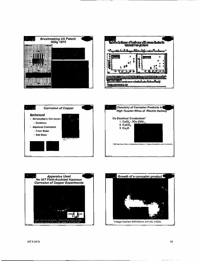
Corrosion of Copper Chemistry of Corrosion Products inHigh Tension Wires of Electric Railway
BackgroundAtmospheric Corrosion Cu Electrical Conductors*
-Oxidation 1. - CUI2 - 3Cu (OH) 2
* Aqueous Corrosion 2. CuC0 3
- Fresh Water -. CU20
- Salt Water -.... OV High T~n=,on Wir..f Japan- El.0rl Railway In Y. .. ygm.. Worltoff. Corollo 12. p146(1961)
Apparatus Used Growth of a corrosion roductfor IA T Field-Assisted Aqueous
Corrosion of Copper Experiments
EI-1-~~ CR~ iskd-, ~h .1g t.-
ScuVoltage Gradient 500V/25mm, 1=5 mA, t=300s
IAT.R 0419 19

Up Growth CircleExperiment #42 Experiment #44
lnalytical Electron Microscopyf Aqueous Corrosion Products] Measured rate of growth of corrosion products - 0s et
+Two different morphologies observed
A (Left) Is fine - submicron-and feathery; B (Right) Is glob~ular - 5 micron
+Variation in chemical composition -
Cu & 0 in EDS of A (Left); Cu, C, & O In EDS of B (Right)
+Any similarities to wear debris from GA Nov 2003 Tests?
= "Copper Oxidation KineticsHow to inhibit the oxidation of copper
One way Is to Introduce a barrier layer at the surface that is impervious to thetransport of either copper or oxygen. This is the mechanism that, for example,protects aluminum from extensive oxidation even though aluminum is intrinsically avery reactive metal. In the case of aluminum, It is the formation of a self-passivatingbarrier layer of aluminum oxide that stops further oxidation.
The second way to inhibit oxidation Is to block the transport of Cu- ions through theCu20. This is the mechanism that leads to the dramatic reduction in the oxidationrate of copper samples which have been ion implanted with B or Al**. In thesecases, large effects are observed for total implants of less than one monolayer (i.e.1015 atoms cm -3). Mg additions to Cu can produce MgO surface barriers*.
* WA. L-f-or eat. ma. tals Chemistryd Physicsl 41 (I " s)192-1 NPJ. DM , W.Lanfrd, S. Hy-,s an SP., Mura , J. Appi. Phys , 74 (13) 13X11
)AT.R 0419 20

w"pper Carbonate ThermochemisThe Copper-Carbon Dioxide System*6==7
>'Negligible Cu-CO2 reactivity at 300K up to 5 atmospheres [1].
>However, when Cu is partially covered with adsorbed 0, asurface carbonate forms.
>The presence of CO2 gas at a pressure as low as 0.05 mbarallows the retention of the carbonate up to 400K.
A4333315t ,.S• •,, , 33 33 34 *3 , 3.' F 3 O 3.33. 30.3 ZS-The DTA curve shows a strong The TG curve indicates only
IIIr=u.33co s Sns vo. P B. I-- 11. 1-n- -. 0) and sharp endothermic peak one step for the process ofwith a minimum at 575K thermal decomposition.
F. Next Steps toward Electromigration BasicsBetter HPM Brushes
4.0 T= 105fCt High current densities can
n t .cause the transport ofI. Revisit Design - Model EM Loads (Space/Time) 3,0 mass in metals
2.5 U Occurs by transfer ofIt. Improve In-situ Measurements and Forensics 2.0 momentum from electrons
0 . to positive metal ionsIll. Capture lessons learned from GA & earlier .. . . 0 Metal Ions in sometests, create hi-fi model of fiber/slip ring wear 204 2 20t2 2016 regions pile up and voidsperformance (+/-), then build and test better t... -. , + form in other regions
brushes U Pileup can short-circuit
adjacent conductors,
whereas voids can result
in open circuits
Build a Wear Model-eg Use wear fragment massand size distribution data
Rabinowicz* determined of the mass of wear fragments using auto-radiographic techniques. The size distribution of copper wear fragmentstransferred during sliding on mild steel was measured experimentally, andusing these data the size distribution of the metallic junctions was calculated.The effect on the junctions of an increase of load was analyzed, and it wasshows that the size of the largest junctions, and hence the mass of the largestwear particles, varied much less than does the applied load. In experiments ofmild steel sliding on copper carried out to confirm these calculations, the massof the largest fragments was found to vary approximately as the 0.3power of the load.
E. -,-3 Qutl Study of th Wear, -1953 p- Phy, S.- B. a62-936A Is..11 (Not3r19M3)
IAT.R 0419 21

APPENDIX E. IAT Paper P.0742. 2004.
EXPERIMENTS ON THE OXIDATION OF COPPERIN AN ELECTRICAL FIELD
Eric BierschenkInstitute for Advanced TechnologyThe University of Texas at Austin
Abstract-When copper is oxidized in high electric fields in an aqueous media, a fern-
like growth phenomenon is observed. This fern-like growth starts at the cathode and
grows toward the anode. Small, hair-like growths were also observed growing off the
cathode. These hair-like growths were of small diameter (< 0.1 mm) and never exceeded
more than 20 mm in length. To observe these phenomena, two copper terminals were
placed in distilled water. Voltage was applied between the two terminals. In about 10
min, the fern-like growth appears directly beneath the cathode. All the experiments were
conducted so as to observe and discover the factors determining the growth. Growth
kinetics was controlled by field concentration, electrode geometry, and by time and
temperature.
INTRODUCTION
Different experiments were conducted with multiple variations to further examine the
properties surrounding the oxidation of copper in an electric field. All the experiments were
conducted in an aqueous media to replicate selected conditions that conductors in a naval railgun
would experience while at sea. Different variations include the presence of an electrolyte, the
presence of a dielectric, differently shaped terminals, and differently shaped culture dishes.
Electrical fields were applied using a Glassman High Voltage instrument. The maximum voltage
obtainable on the apparatus is 10 kV, with a limiting factor of 10 mA of current. This same
apparatus was used for every experiment, along with copper terminals. The immersed electrodes
were varied.
EXPERIMENTS
Wider Dish. To study the extent to which the growth can persist, the initial experiment was
conducted in a wider dish. The larger reaction cell also allows examination of other phenomena
not observed when the experiment was conducted in the small dish. The terminals were placed
45 mm apart in a 150 mm Petri dish.
IAT.R 0419 22

Results. The growth had reached 25 mm length within five minutes and continued to grow rather
quickly. At 15 min, the growth had already reached the anode 45 mm away. A great number of
particles were seen floating around the dish at about 60 min. These particles moved in a circular
manner around the dish until they connected to the end of the fern-like growth; this was observed
to be how the growth came about. After 210 min, a large leaf-like shape appeared between the
two terminals. The structure was composed of many lines of debris, all flowing from the cathode
toward the anode, as shown in Fig. 1. Upon completion of the experiment, after five hours there
were distinct lines running between the terminals that filled the entire Petri dish. The lines grew
in such a manner that it appeared as though they were following electric field lines.
Electric Field Tester. This experiment was conducted with one cathode and two anodes. The two
anodes were situated on opposite sides of the Petri dish, and the cathode was placed directly
between them. It was then predicted that the fern-like growth would form an hourglass shape, as
shown in Figure 2, growing off the cathode and branching off toward the two anodes.
Results. Upon completion of the fern-like growth, 90 min, it was determined that the growth was
almost identical to the predicted outcome, as shown in Fig. 3. The general shape was the same,
but the actual lines observed in the previous experiment failed to appear. These findings prove
that the growth follows the electric field lines.
Figure 1. The feather Figure 2. The predicted outcome for Figure 3. Actual outcome for "Electricshape has completely "Electric Field Tester." Field Tester." Time: 90 minutes.
reached the anode. Time:210 minutes.
Salt (Unmeasured Amounts).The presence of an electrolyte, sodium chloride, was predicted to
have a new effect on the fern-like growth. It was previously unknown what the effect would be,
but it was hypothesized that the rate of development of the fern-like growth would be faster.
IAT.R 0419 23

Results. The salt had a surprising affect on the reaction. Not only did the fern-like growth not
appear, but a new growth emerged. A milky blue cloud appeared around the anode, and a blue
streak appeared off the cathode. This all took place within 25 min. The blue streak was then
accompanied by a dark green, almost black, streak next to it. When the experiment was stopped
at 150 min, the streak has gotten longer, as shown in Fig. 4, and the tip of the anode was yellow.
This sample was then further analyzed with a scanning electron microscope (SEM). The green
part of the streak was observed to be comprised of crystalline growths, as shown in Fig. 5, while
the dark part of the streak was comprised of hexagonal-shaped growths, as shown in Fig. 6.
Salt (Measured Amounts). The previous experiment was replicated using the general formula
Figure 5. SEM photograph ofFigure 4. The bluish streak material from the green streak. Figure 6. SEM photograph
of material from the blackobserved in "Salt: Measured Note the crystalline shape of the streak. Note the hexagonal
Amounts." Time: 150 minutes. sample. shape of the sample.
for artificial seawater, which is 2.4 g of sodium chloride for every 97.6 g of water. This was
predicted to lower the resistance drastically and to speed up the reaction.
Results. The findings suggest that the presence of the salt actually slowed down the reaction, and
it had a drastically different outcome than the previous salt experiment. The cathode began
letting off bubbles at about 1 h. It took an entire 6 h before the reaction was complete. The water
turned a turquoise blue color, with a few blotches of discoloring. Upon evaporation of the water,
crystals were observed to be spread evenly on the bottom of the Petri dish, as shown in Fig.7.
These crystals were shaped like salt crystals, but much larger.
Ferric Chloride. The presence of a new electrolyte, FeC13, was introduced to study the effect it
would have on the reaction.
IAT.R 0419 24
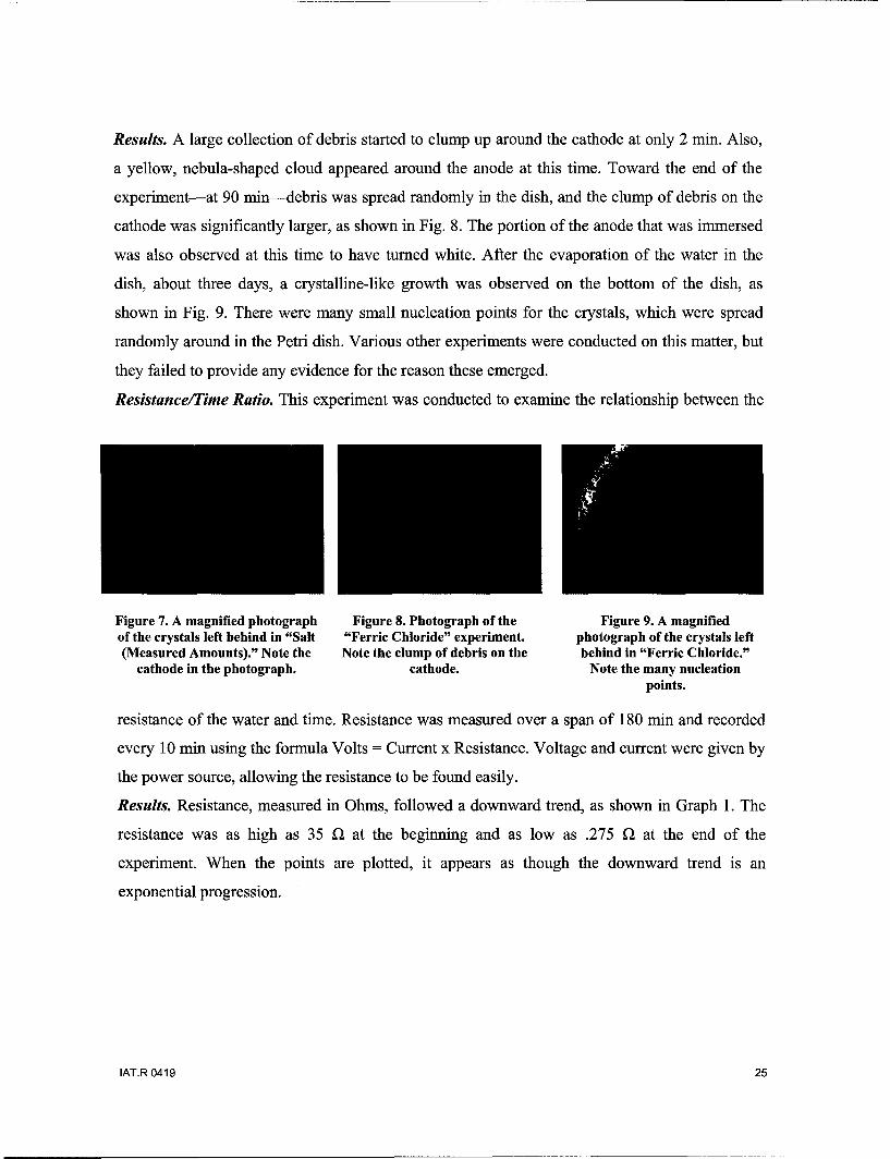
Results. A large collection of debris started to clump up around the cathode at only 2 min. Also,
a yellow, nebula-shaped cloud appeared around the anode at this time. Toward the end of the
experiment-at 90 min-debris was spread randomly in the dish, and the clump of debris on the
cathode was significantly larger, as shown in Fig. 8. The portion of the anode that was immersed
was also observed at this time to have turned white. After the evaporation of the water in the
dish, about three days, a crystalline-like growth was observed on the bottom of the dish, as
shown in Fig. 9. There were many small nucleation points for the crystals, which were spread
randomly around in the Petri dish. Various other experiments were conducted on this matter, but
they failed to provide any evidence for the reason these emerged.
Resistance/Time Ratio. This experiment was conducted to examine the relationship between the
Figure 7. A magnified photograph Figure 8. Photograph of the Figure 9. A magnifiedof the crystals left behind in "Salt "Ferric Chloride" experiment, photograph of the crystals left(Measured Amounts)." Note the Note the clump of debris on the behind in "Ferric Chloride."
cathode in the photograph. cathode. Note the many nucleationpoints.
resistance of the water and time. Resistance was measured over a span of 180 min and recorded
every 10 min using the formula Volts = Current x Resistance. Voltage and current were given by
the power source, allowing the resistance to be found easily.
Results. Resistance, measured in Ohms, followed a downward trend, as shown in Graph 1. The
resistance was as high as 35 Ql at the beginning and as low as .275 92 at the end of the
experiment. When the points are plotted, it appears as though the downward trend is an
exponential progression.
IAT.R 0419 25

Graph 1. Resistance/time ratio.
Voltage/Growth Ratio. In order to observe a relationship between the voltage and the rate of
development of the fern-like growth, the following experiment was conducted. The expansion of
the fern-like growth was measured in millimeters for varying voltages. The voltage varied
between 0.1 kV and 1 kV, with the measurements taking place at 900 s for every specimen.
Results. By viewing the graph, one can conclude that the development of the fern-like growth is
related to the voltage, as shown in Graph 2. The growth increases continuously for every
increase in voltage. The growth spans between no growth for 0.1 kV and 43 mm for 1 kV.
Graph 2. Voltage/growth ratio.
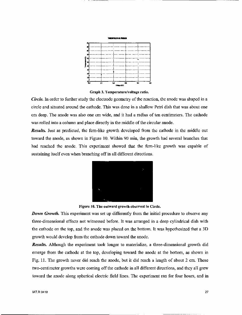
Temperature/Voltage Ratio. This experiment was conducted to observe the relationship between
the voltage and the temperature of the water. The voltage varied from 0.1 kV to 0.5 kV, and the
temperature was taken at 600 s.
Results. The findings suggest that there is indeed a relationship between the voltage and the
temperature of the water, as shown in Graph 3. The relationship suggested by the findings is an
increase in temperature for every increase in voltage.
IAT.R 0419 26
• .. . ........... . . ......... . .. L . . ........... . . ................... .....................
.. . . .. . . . . .:. .................. . .................. •. ..................... . ...................
S... .. .. .. .. .. ..r .. .. .. .. .. .. .. -............ I."..,. .... r ......... I............ z.... .................320
0 01 02 0 GA 0A
Graph 3. Temperature/voltage ratio.
Circle. In order to further study the electrode geometry of the reaction, the anode was shaped in a
circle and situated around the cathode. This was done in a shallow Petri dish that was about one
cm deep. The anode was also one cm wide, and it had a radius of ten centimeters. The cathode
was rolled into a column and place directly in the middle of the circular anode.
Results. Just as predicted, the fern-like growth developed from the cathode in the middle out
toward the anode, as shown in Figure 10. Within 90 min, the growth had several branches that
had reached the anode. This experiment showed that the fern-like growth was capable of
sustaining itself even when branching off in all different directions.
Figure 10. The outward growth observed in Circle.
Down Growth. This experiment was set up differently from the initial procedure to observe any
three-dimensional effects not witnessed before. It was arranged in a deep cylindrical dish with
the cathode on the top, and the anode was placed on the bottom. It was hypothesized that a 3D
growth would develop from the cathode down toward the anode.
Results. Although the experiment took longer to materialize, a three-dimensional growth did
emerge from the cathode at the top, developing toward the anode at the bottom, as shown in
Fig. 11. The growth never did reach the anode, but it did reach a length of about 2 cm. These
two-centimeter growths were coming off the cathode in all different directions, and they all grew
toward the anode along spherical electric field lines. The experiment ran for four hours, and in
IAT.R 0419 27

this time period, the water began to move in a 3D convective manner between the two terminals.
Debris could be observed moving in the current, but it all slowly made its way either to attach to
the growth or to rest on the bottom. At the end of the experiment, a quantity of the debris
managed to make its way to the bottom, where it stayed. This experiment showed more than the
previous experiment had shown with its circular-shaped anode. This experiment showed that the
fern-like growth was able to hold itself together, even in three dimensions.
Figure 11. The three-dimensional growth observed in Down Growth. Note the debris movement in the waterbelow the cathode.
Castor OiL The presence of a dielectric, castor oil, was introduced to the experiment to observe
what effects it would have on the reaction. It was hypothesized beforehand that the presence of a
dielectric would slow, if not completely stop, the reaction. The solution was half water, half oil.
The cathode was placed in the castor oil, and the anode was placed in the water.
Results. Upon turning on the power, the oil split in half and allowed the water to flow between
the two terminals. At only 15 min, the water contained millions of bubbles that occupied the
entire surface of the water. The origin of all the bubbles was the cathode, which began letting off
bubbles at only 5 min. It took an entire hour for the fern-like growth to reach the anode, as
shown in Fig. 12, which supports the original hypothesis that the dielectric would slow the
reaction down.
Figure 12. The growth observed in Castor Oil. Note the splitting of the oil to allow the water to run betweenthe two terminals.
IAT.R 0419 28
Magnet. A magnet was introduced to the experiment to observe any effect it would have on the
fern-like growth. It was theorized beforehand that the magnet would have either a push or a pull
on the fern growth. In order to observe this properly, the magnet was placed directly beneath the
Petri dish and offset to one side. This was done so that the metallic characteristics of the magnet
would not have an affect on the reaction, and the magnet was offset to one side so that it would
be easier to observe a push or a pull on the growth. The voltage was kept at 0.2 kV for the first
25 min and turned down to 0.05 kV for the remaining 95 min.
Results. The magnet did not appear to have an effect on the fern-like growth, as shown in
Fig. 13. Even when the voltage was turned down to 0.5 kV, it did not have any affect at all. The
growth emerged normally, and it reached the anode as usual.
Figure 13. The growth observed in Magnet. Note the gold-colored magnet offset to the left. Also note thatthere is no effect on fern growth.
Figure 14. The growth observed in Teardrop. Note that the fern-like growth emerges from the rounded sideof the teardrop-shaped copper piece and not from the pointed side.
IAT.R 0419 29

Small Teardrop. A piece of copper was placed in the Petri dish along with the terminals to
further study the electrode geometry. The piece of copper was cut into the shape of a teardrop,
and it was placed in such a manner that the rounded side of the teardrop was closer to the anode
than the pointed side. This was done because it had been observed previously that the fern-like
growth favored sharp points for nucleation locations. The experiment was designed to show
which the fern-like growth favored more, distance or a sharp point for a nucleation site.
Results. The fern-like growth emerged on the rounded side of the teardrop, which was the side
closer to the anode, as shown in Fig. 14. These findings suggest that the distance between the
anode and the copper piece plays a bigger role in determining nucleation sites than does the
presence of a sharp point.
CONCLUSION
All the findings of the experiments suggest that there is still much to be discovered about the
oxidation of copper in high electric fields. This series of experiments helps to further understand
the factors controlling growth, field concentration, electrode geometry, and the effect of time and
temperature on growth, but there is more to discover than can be observed through these
experiments. Future experiments should be focused more on artificial seawater being used as the
aqueous media, the direction that the Navy would like to go with research in this area. Further
studies of the oxidation of copper in artificial seawater will help to find an efficient way to
reduce corrosion and oxidation of copper for future naval railguns.
ACKNOWLEDGMENTS
Thank you to Martha Simmons and Reginald Jim Allen at the lab for their help with the
experiments. A special thanks to Chadee Persad for his leadership and guidance.
IAT.R 0419 30
APPENDIX F. Current Collection and Fiber BrushesIAT Technical Note: IAT TN.0288
Author: Dr. Ian R. McNabDate: 29 November 2004
IntroductionIn addition to the references on fiber brushes provided recently by Dr. Chadee Persad to the ONR
Workspace in connection with the Superconducting Homopolar Motor project, some papers in early HolmConferences (published in the IEEE Transactions on Components, Hybrids and ManufacturingTechnology) and the papers in the 1982 Volume Number 78 of WEAR may be relevant to these efforts.
DARPA/ONR/Westinghouse Current Collection research (1978-83)Westinghouse Research Laboratories in Monroeville, PA had the primary contract from ONR for
the development of current collection systems under an effort sponsored by the Materials Science Officeof (D)ARPA 9. The purpose was to develop current collection technology for homopolar machines for shippropulsion. While the Annapolis team of Tim Doyle, Howard Stevens, Dr. Neil Sondergaard and theircolleagues were developing liquid metal current collection systems for their homopolar motor effort,Westinghouse, having investigated NaK systems (and I was part of this), concluded that liquid metalswere inappropriate for ship use and turned to solid "brushes". Westinghouse initially looked at solidgraphite and metal-graphite brushes, starting from the work done at Westinghouse (and GE) during WWII on the high altitude brush dusting problem for aircraft generators. As part of this, close connectionexisted between Westinghouse and their favored conventional brush supplier, the Stackpole Carbon Co.of St. Mary's, PA. Building on the work done in the Britain at IRD Co., (I was also involved in this) theemphasis turned to metal-plated fiber brushes. Richard Marshall from Australia also contributed some ofhis ideas to this work based on his experience with Morganite copper-graphite brushes on the 500 MJCanberra homopolar generator. Westinghouse built a large number of brush test rigs to evaluate differentbrush concepts, including the MEBT (= Machine Environment Brush Tester), that is still in use today.
Much of the work reported was undertaken under the ONR Contract N00014-81-C-0464 withWestinghouse. I no longer have the detailed reports from that Contract but they may exist in ONR orDTIC.
Although Westinghouse had the main contract from ONR but an integral feature of the researchapproach we followed was the coordination with other government organizations, expert consultants anduniversities. The primary universities involved were MIT (Prof. Ernie Rabinowicz), Syracuse (Prof.Richard Vook), North Carolina State University (Prof. Ralph Burton and Dr. Michael Bryant), CarnegieMellon University (Prof. William. Hughes), and the University of Virginia (Profs. Heinz and DorisWilsdorf). Consultants included Dr. Brian Williamson (UK) and Dr. Charles Bronariek (TuskageeInstitute - previously Westinghouse).
Out of this work, and the earlier work in the UK that I reported at the Brush Workshop on 19February 2004 came the interest in fiber and wire brushes that led to where we are today.
Holm ConferencesThe annual Holm conferences provided a useful forum in which to meet and discuss the current
collection work we were performing for ONR. The papers were given at these conferences are shown in
9 At that time ARPA was used, now it is DARPA. Dr. Arden Bement was the head of the Materials Science Officeand Dr. Mike Buckley was the Project Manager.
IAT.R 0419 31

Table I. We deliberately introduced the concept of linked papers in which the studies for ONR werereported, as is evident from the paper titles.
Table I. Papers relating to the Westinghouse ONR Research Program
Holm IEEE Trans. Authors TitleConference No. Volume
2 3rd. Chicago, IL. CHMT-1. I.R. McNab Pulsed High Power Brush ResearchNov. 1-3, 1977 March 1978
J.L. Johnson & High Current Brushes, Part I: Effect of Brush andL.E. Moberly Ring MaterialsP.K. Lee & High Current Brushes, Part II: Effects of Gases andJ.L. Johnson Hydrocarbon Vapors
2 4 the Chicago. IL CHMT-2. I.R. McNab & High Current Brushes, Part III: PerformanceSept. 1978 March 1979 J.L. Johnson Evaluation for Sintered Silver- Graphite Grades
P. Reichner & Shunts for High-Current Density BrushesO.S. TaylorO.S.Taylor & Mechanical Load Aspects of High Current BrushP. Reichner System DesignR.A. Marshall & Pulsed High Power Brush research, Part III:R.M. Slepian Experiments at 15.5 MA/m 2 and 277 m/s.
2 5th. Chicago, IL CHMT-3. P.K. Lee High-Current Brush Material development, Part 1:Sept. 1979 March 1980 Sintered Metal-Coated Graphite.
R.W. Vook, et Elemental Surface Composition of Slip Ring Copperal. as a Function of Temperature.P. Reichner Metallic Brushes for Extreme High Current
Applications.I.R. McNab & High Current Density Carbon Fiber BrushW.R. Gass experiments in Humidified Air and Helium.J.L. Johnson & High Current Brushes, Part IV: Machine EnvironmentO.S. Taylor TestsS. Dillich & Effects of Surface Films on the Performance of SilverD. K-Wilsdorf. Graphite Electric Brushes.R.M. Slepian High Current Brushes, Part V: Subdivided Monolithic
Brushes at Very High Current Levels.J. Schreurs, High Current Brushes, part VI: Evaluation of SlipJ.L. Johnson & Ring Surface Films.I.R. McNab
2 6 th, Chicago. IL CHMT-4. P. Reichner High Current Tests of Metal Fiber BrushesSept 29-Oct 1, March 19811980.
J. Schreurs, J.L. Characterization of Thick Films formed on Slip RingsJohnson & I.R. during High Current Density OperationMcNabB. Singh & In Situ AES Characterization of Rotating ElectricalR.W. Vook ContactsP. Reichner Pressure-Wear Theory for Sliding Electric ContactsP.K. Lee High Current Brush material Development, Part II:
Metal-Solid Lubricant Coated WiresR.A. Marshall High Current & High Current Density Pulse Tests of
Brushes and Collectors for Homopolar Energy Stores.
IAT.R 0419 32

1981 Current Collection ConferenceIn 1981, it was decided that interest in current collection for electric machines was at a sufficient
level that it might be useful to hold a special conference dedicated solely to that topic. Accordingly, aconference was arranged to be held in Chicago on Sept 23-25, 1981. The Conference was co-sponsoredby the Westinghouse Research Laboratories and by ONR and I acted as conference chairman. VolumeNumber 78 of Wear was set aside to cover the Proceedings of this Current Collection Conference and itwas also published by Elsevier Sequoia as a separate volume (ISBN 0-444-75011-8) in 1982. Only a fewcopies of this volume were made - mostly for the 50 or so attendees. I still have a couple of these and ourlibrary obtained one on-line from eBay (or similar) a few months ago that belonged to a formerWestinghouse employee (Owen Taylor).
I provided the Foreword to the volume and that is attached here as an Acrobat file, together withthe Index to the volume.
Fiber Brushes in RailgunsThe early use of fiber brushes as armatures in railguns was initially done by the same
Westinghouse researchers and for the same reasons - they offered good electrical contact under stressingconditions of acceleration and current. The initial tests were done in a small (10mm x 10 mm square borerailgun, called ELF) and reported by David Ross and Dan Deis at the 1 st Electromagnetic LauncherSymposium in San Diego in November 198010. Later (and noted as a footnote to the Foreword in theWear volume) we used a larger fiber bundle in the 50 mm x 50 mm square bore EMACK system duringtests in January 1982 and achieved very high velocities. After this system was delivered to the ArmyARDEC Laboratories in Picatinny, NJ Army the same technology was used there. One of theWestinghouse engineers, Dr. Gerry Ferrentino moved to work at ARDEC and, together with HansKolkurt from TNO in the Netherlands, who came there as an exchange person in 1984, picked up thistechnology and developed it further. The Dutch and TNO are no longer working on electric guns but theresidue of this interest now lies with the French group at the Institute Saint Louis in France, where severalvariants of the fiber brush technology have been tested in their EM guns and research is still continuing.Most of that work has been reported in the twelve International EM Launcher Symposia, the proceedingsof which have been published in the IEEE Transactions on Magnetics from 1982 to 2005.
Fiber Brush PatentsAs the start of a data base on patents that ONR might wish to assemble, I have attached here a list
of patents relating to brushes and current collection that I know about. This is embarrassingly "McNab-centric" at present but only because I have not had time to add other patents that I know exist. I know thatDr. Persad and many of you have many more. I certainly have more in my files and will find them andadd to the list. Copies of three of the patents are also attached here as PDF files. Some of the namesmentioned here could provide a useful basis for a patent search.
Where are they now?Much of the work discussed above was performed twenty or more years ago. One might ask
where these folks are now. In some cases, there are sad answers (Tony Appleton died ten years ago, JanSchreurs died in his early 50's). Many have retired: Phil Reichner (in the Pittsburgh area); Geoff Wilkin(in Northumberland, UK); Dick Marshall (in Austin). I have lost touch with many of the Westinghouseresearchers (Larry Moberly, Johnny Johnson, P. K. Lee). Some have moved on and are no longerinterested in this field (e.g., Owen Taylor). Fortunately, a few, such as Professor Michael Bryant", arestill around and are still interested in this field.
10 Included in the Proceedings of that conference published by the IEEE in the Trans. Mag, January 1982.11 Now at UT Austin.
IAT.R 0419 33

Patents
G.A. Wilkin, I.R. McNab and A.D. Appleton. "Current Transfer Devices for Electrical Machines." USPatent 3,648,088. Date granted: March 7, 1972.
I.R. McNab, "Electrical brush structure, "US Patent 3,668,451. Date granted: June 6, 1972.
I.R. McNab, "Current transfer in homopolar machines." US Patent 3,681,633. Date granted: August 1,1972.
I.R. McNab and G.A. Wilkin, "Current transfer brush. " British Patent 1,325,434. Date granted August 1,1973.
I.R. McNab, "Current transfer in homopolar machines." British Patent 1,326,731. Date granted August15, 1973.
I.R. McNab, "Current transfer in homopolar machines." British Patent 1,328,189. Date granted August30, 1973.
I.R. McNab, "Improvements in and relating to current transfer devices in homopolar electrical machines."British Patent 1,332,786. Date granted: October 3, 1973.
G.A. Wilkin, I.R. McNab and A.D. Appleton. "Current transfer devices for electrical machines." BritishPatent 1,337,591. Date granted: November 14, 1973.
G.A. Wilkin and I.R. McNab. "Duplex carbon fiber brush, " British Patent 1,388,123. Also patented inAustralia # 476,668; Canada #983,561 (as "Current Transfer Brushes, Granted: Feb 10, 1976); France #73 07188; Italy # 979,591; Sweden # 73.02733.6; Switzerland # 551,088.
I.R. McNab. "Current transfer in homopolar machines." US Patent 3,796,900. Date granted: March 12,1974.
G.A. Wilkin and I.R. McNab. "Current transfer brushes." US patent 3,821,024. Date granted: June 28,1974.
I.R. McNab and P. Reichner. "Environment and brushes for high-current rotating electrical machinery."US Patent 4,277,708. Date granted: July 7, 1981.
IAT.R 0419 34

V
Contents
FOREWORD
Advances in electrical current collection ............................. 1I. R. McNab (Pittsburgh, PA, U.S.A.)
I. FUNDAMENTAL ASPECTS OF SLIDING CONTACTS
In situ Auger electron spectroscopy characterization of wet-CO2 -1ubricated slidingcopper electrical contacts ....................................... 7
B. H. Hwang, B. Singh, R. W. Vook and J. G. Zhang (Syracuse, NY, U.S.A.)
Microstructural characterization of rotating Cu-Cu electrical contacts in vacuumand wet CO 2 environments ....................................... 17
B. Singh, J. G. Zhang, B. H. Hwang and R. W. Vook (Syracuse, NY, U.S.A.)
The temperature rise at sliding electrical contacts .......................... 29E. Rabinowicz (Cambridge, MA, U.S.A.)
Thermal stability in graphite contacts ............................... 39J. B. P. Williamson (Malvern, Gt. Britain)and N. Allen (Pittsburgh, PA, U.S.A.)
Frictional and electrical interactions in current collectors ..................... 49M. D. Bryant and R. A. Burton (Raleigh, NC, U.S.A.)
Thermornechanical effects in high current density electrical slip ringsT. A. Dow (Raleigh, NC, U.S.A.) and J. W. Kannel (Columbus, OH, U.S.A.)(This paperis published in Wear, 79 (1982) 93)
II. FIBER BRUSHESLow wear metallic fibre brushes ................................... 59
L. Boyer, J. P. Chabrerie and J. Saint-Michel (Gif-sur-Yvette, France)
A homopolar motor for the demonstration of new high current brushes ......... 69P. Reichner and V. B. Doshi (Pittsburgh, PA, U.S.A.)
Carbon fibre fringe brush ....................................... 81B. R. G. Swinnerton (Swansea, Gt. Britain)
Operating experience with the fringe fiber brush ........................ 93A. Marcus (Wallingford, CT, U.S.A.)
Controlled conductance current switching in low voltage high current d.c. machines 109G. T. Hummert and R. M. Garrett (Pittsburgh, PA, U.S.A.)
III. LIQUID METALS
High current liquid metal collectors ................................ 117R. A. Marshall, B. D. Hatch and R. C. Kumpitsch (Schenectady, NY, U.S.A.)
Low melting solder for slip ring current collectors ....................... 127J. T. McLane (Annapolis, MD, U.S.A.)
IV. HIGH SPEED SLIDING CONTACTS
Ultrahigh speed fiber brush design and tests ........................... 139W. H. Lupton (Washington, DC, U.S.A.) and P. Reichner (Pittsburgh, PA, U.S.A.)
Solid brush system evaluation for pulsed high current applications ............. 1510. S. Taylor and W. F. Hannan (Pittsburgh, PA, U.S.A.)
Elsevier Sequoia/Printed in The Netherlands
IAT.R 0419 35

vi
Contact phenomena at hypervelocities ............................... 163J. P. Barber and D. P. Bauer (Dayton, OH, U.S.A.)
Diffusion skin effects in ultrahigh velocity laminated current collectors ......... 171W. F. Hughes (Pittsburgh, PA, U.S.A.) and F, J. Young (State College, PA,U.S.A.)
Experimental determination of the contact friction for an electromagneticallyaccelerated arm ature .......................................... 189
D. P. Ross, G. L. Ferrentino (Pittsburgh, PA, U.S.A.) and F. J. Young (StateCollege, PA, U.S.A.)
V. MONOLITHIC BRUSHES
U.K. Ministry of Defence current collection programme for superconductinghom opolar m otors ............................................ 201
T. C. Bartram (Newcastle-upon-Tyne, Gt. Britain)
Wear-induced profiles of brushes on eccentric rotors ..................... 207P. Reichner (Pittsburgh, PA, U.S.A.)
High current brushesVIII: Effect of electrical load ..................................... 219
J. L. Johnson and J. Schreurs (Pittsburgh, PA, U.S.A.)
Damping characteristics of solid brush current collection systems .............. 233C. A. Broniarek (Tuskegee Institute, AL, U.S.A.)
Calculation of the conductivity of moulded powder products for contact materials 243A. I. Sviridyonok, N. K. Myshkin and V. V. Meshkov (Gomel, U.S.S.R.)
Polar effects within the sliding contact of metal-containing brushes ............ 249V. A. Belyi, V. V. Konchits and V. G. Savkin (Gomel, U.S.S.R.)
NOTES ON CONTRIBUTORS .................................... 259
IAT.R 0419 36

Wear, 78 (1982) 1 - 6
Foreword
Advances in electrical current collection
1. R. MCNABElectro technology Department, Westinghouse Electric Corporation Research and Devel-opment Center, 1310 Beulah Road, Pittsburgh, PA 15235 (U.S.A.)
(Received December 1, 1981)
During the last decade, substantial advances have taken place in severalareas of technology concerned with the transfer of electrical current acrosssliding interfaces. The requirement to transfer current from moving metalsurfaces to sliding conductors is essential for many electrical machines, andresearch in this field goes back to the earliest days of the electrical industry.
In recent years several advanced rotating and linear electrical machineconcepts have been developed which depend for their success on the efficienttransfer of current across sliding interfaces. For example, the steady stateoperation of brushes at 8 MA m- 2 is the goal for advanced land or sea pro-pulsion machinery. Even higher current densities (18 MA m-2 ) and speeds(300 m s') are required for the subsecond operation of inertial storagepulsed power sources. Speeds and current densities more than an order ofmagnitude higher, although for millisecond pulses, may prove to be necessaryfor linear electromagnetic projectile accelerators. In all these cases therequirement for the efficient transfer of electrical current complicates thefrictional and wear effects that take place at mechanically contacting slidinginterfaces.
In the U.S.A. the major research and development efforts during thelast few years have been centered on the David Taylor Naval Ship Researchand Development Center, Annapolis, MD, and at Westinghouse Research andDevelopment Center, Pittsburgh, PA. The former effort focused on the useof liquid metal techniques while the research of the Westinghouse scientists,and their colleagues in associated universities, has been concentrated on solidor multielement brush techniques. The Westinghouse program was supportedby the Materials Science Office of the Advanced Research Projects Agencyof the U.S. Department of Defense (DARPA) and monitored by the Officeof Naval Research (ONR). Throughout the program regular Workshop meet-ings were held to enable the contributing researchers to meet and exchangeinformation. However, since attendance at these Workshops was limited andthe proceedings were not published, it was decided to hold a full Interna-tional Conference at which a combination of researchers, manufacturers and
Elsevier Sequoia/Printed in The Netherlands
IAT.R 0419 37

2
users could interact to discuss the recent advances in this field. This con-ference, cosponsored by the Office of Naval Research and by WestinghouseElectric Corporation, was held in Chicago on September 23 - 25, 1981.Although relatively small in numbers, with approximately 60 attendees, theConference brought together active experts in this field from the U.S.A.,Canada, France, Gt. Britain and China, and two papers were submitted fromthe U.S.S.R. In view of the difficulties inherent in this subject it is likelythat the combined efforts of these international experts with their spectrumof research and industrial perspectives will be needed to enable furtherprogress in this subject to be made.
Substantial advances in liquid metal current collection techniques havebeen made during the last decade under the auspices of the U.S. Navyprogram. The work reported here shows that the use of the "narrow gap"collector geometry, based on the use of surface tension effects in a metallicbraid that is virtually in touching contact with the rotor surface, enables theproblems associated with liquid metal expulsion as a result of the J X Bforces to be solved, and long term stable operation has been demonstrated.The major problem with liquid metals is the choice of fluids available, mostof which have significant disadvantages. Sodium and potassium and theiralloys (Na-K) are very reactive chemically while mercury is toxic andGa-In alloys form contact-disrupting black powder oxides in oxygen-containing atmospheres. Despite the excellent performance observed in care-fully controlled laboratory conditions, these considerations are likely tolimit the practical use of liquid metals. Some work reported in this meetingwas therefore devoted to discovering whether less reactive liquid metals, suchas low melting point alloys, can be used for this application.
In most electrical machinery at present in operation, the current trans-fer function is provided by carbon-based brushes supplied by the brushindustry. In most cases the operation of such brushes is limited by a currentdensity-speed-wear loss envelope for which typical current densities andspeeds are 0.2 MA m-2 and 40 m s-1. Evaluation of the reasons for theselimitations shows that the primary cause is the build-up of a complex film,mainly cuprous oxide, on the surface of the slip ring or commutator. Inaddition, the choice of the carbon-based brush is generally mandated by therequirement to develop a high voltage to force the current to flow into a newcircuit, i.e. to commutate. For some of the new machine applications men-tioned above, the commutation function may not exist, or may be lessarduous, thereby opening the way to other brush concepts or materials.
As reported here, the work under the DARPA-ONR-Westinghouseprogram has shown that solid or monolithic brushes made from relativelyconventional materials can be operated up to much higher current densitiesand speeds than previously considered possible provided that (i) carefulatmosphere control (non-air) is provided, (ii) brush and environment tem-peratures are controlled, (iii) adequate mechanical control is maintained and(iv) optimal materials are chosen. Under these conditions several remarkableadvances have taken place in recent years.
IAT.R 0419 38

(i) Multiple brush assemblies have been operated continuously inmachines at current densities in excess of 1.5 MA m- 2 at 40 m s-.
(ii) Individual brushes have been operated in steady state conditions tocurrent densities of 6 MA m-2 at 15 m s-1.
(iii) Multiple brush assemblies have been pulsed to more than 3 MAm 2 at 40 m s-1.
(iv) Prototypic multiple brush modules have been pulsed at currentdensities of 18 MA m- 2 for periods of 0.25 s with simultaneous speeds up to280 m s-1.
Supporting these practical advances has been a wide range of funda-mental studies into materials and surface physics at Westinghouse and inassociated universities. These studies have encompassed aspects such as thefollowing.
(i) Advanced diagnostic techniques (scanning electron microscopy,Auger analysis etc.) are used to determine the physical state of the materials.
(ii) Theoretical and practical studies on the electrical and mechanicaleffects taking place at the sliding interfaces are carried out.
(iii) Evaluations are made of materials compatibility and interactions.(iv) New wear models are developed.(v) The mechanical conditions imposed by practical materials and
engineering limits and their effects on the sliding contact process areevaluated.
While much has been learned, and is reported in this volume, it is clearthat these investigations are far from complete and that more remains to bedone if we are to reach the goal of a unified theory to explain sliding contactbehavior.
An alternative to the use of liquid metals or monolithic blocks ofcarbon, or metal-carbon, is the multielement contact which in its most com-mon form may utilize the "fiber" brush. Much of the early work in this areawas based on the development of carbon fibers in the 1960s when it wasrealized by researchers in Gt. Britain that this technology would permit aflexible carbon brush having multiple independent contacts to be made. Thishas been found to have some application in a modified form as the fringefiber brush for machines operating in an arduous environment as describedin two papers in this volume. However, for applications where low contactvoltage drops were required, it was found to be beneficial to provide acoating on each individual fiber, for example by electroplating, to provide ahigh conductivity sheath on the high strength fiber. Although brushes havebeen successfully manufactured in this way, studies during the Westinghouseprogram showed that the optimum performance may not require as manycontacts as provided by the standard 8 pm diameter carbon fibers. Conse-quently, new metal fiber brushes have been developed, with typical fiberdiameters of 125 pm. Experiments with these brushes have been verysuccessful showing, for example, continuous operation at very high currentdensities (greater than 10 MA m- 2 ) with very low losses and wear. Aninteresting feature of this work has been that independent groups have
IAT.R 0419 39

4
followed similar lines, with similar results. This technology has been appliedto the pulsed homopolar machine at the Naval Research Laboratory and hasshown successful operation at sliding speeds up to 475 m s-1, which isbelieved to be the highest peripheral speed achieved with sliding contacts inrotational machinery.
This same technology has also been applied to the problems found inswitch ring machines, and results obtained with a combined metal-carbonplus metal fiber brush are described in a paper in this meeting. With thistechnology, current densities of 1.5 MA m-2 were achieved on a continuousbasis. Although still at an early stage, this technology may represent the nextstep in commutation technology after the carbon fiber fringe brush.
Probably the ultimate sliding contact operation is represented by theconditions which exist in linear electromagnetic projectile accelerators. Insuch systems extremely high current densities (of the order of gigaamperesper meter squared) have to be transferred at very high speeds (of the order ofkilometers per second or more). The only feature that makes such a contactfeasible is its transient nature, usually of the order of a thousandth of asecond. Nevertheless, conditions in such contacts are very severe and gener-ally approach melting of the contacts. Research in this field is at a very earlystage but some experimental work is reported here, together with factorsthat influence the successful operation, including electromagnetic transienteffects. (See note added in proof.)
In summary, the work reported here provides a cross section of progressin this field which has traditionally shown relatively slow growth but whereseveral important advances have been made in the last decade. Many of theseadvances have resulted from the DARPA-ONR program and I should like totake this opportunity to thank the Department of Defense program managersfor their advice and encouragement throughout this program, especially A.Bement and M. R. Buckley of DARPA, and R. Seng, R. A. Burton and H. B.Martin of ONR. The financial support offered by the ONR and WestinghouseElectric Corporation that made this conference possible is gratefullyacknowledged. In addition, I should like to express my appreciation of thehelp and advice offered in connection with the organization of this con-ference by R. E. Armington, Chairman of the Holm Conference.
Finally, I should like to thank all the authors and participants formaking this a pleasant and rewarding meeting, and D. J. DiCesare for hersecretarial help in organizing the meeting.
Bibliography
Although the individual papers contained in this volume referencemany of the prior studies in this field, it was considered helpful to enclosethe following more complete list.
C. A. Broniarek and 0. S. Taylor, Mechanical stability of solid brush current collec-tion systems, IEEE Trans. Power Appar. Syst., 99 (6) (1980) 2413.
IAT.R 0419 40

C. P. Chen and R. A. Burton, Thermoelastic effects in brushes with high currentand high sliding speeds, in Proc. Conf on Electrical Contacts, September 1978, IllinoisInstitute of Technology, Chicago, IL, 1978, p. 571.
R. M. Garrett and G. T. Hummert, Controlled conductance current switching inlow voltage, high current DC machines, Int. Cont on Electric Machines, Athens,September 1980.
J. L. Johnson, Monolithic brushes for high current collection applications, in Ex-tended Abstracts 15th Bienn. Conft on Carbon, University of Pennsylvania, Philadelphia,PA, June 22 - 23, 1981, pp. 318 - 319.
J. L. Johnson and 0. S. Taylor, High current brushes. Part IV: machine environ-ment tests, IEEE Trans. Components, Hybrids Manuf Technol., 3 (March 1980) 31.
J. L. Johnson and L. E. Moberly, High current brushes. Part I: effect of brush andring materials, IEEE Trans. Components, Hybrids Manuf. Technol., 1 (March 1978) 36.
P. K. Lee, High current brush material development. Part IT: metal-solid lubricantcoated wires, IEEE Trans. Components, Hybrids Manuf. Technol., 4 (March 1981) 114.
P. K. Lee, High current brush material development. Part I: sintered metal coatedgraphite, IEEE Trans. Components, Hybrids Manuf Technol., 3 (March 1980) 4.
P. K. Lee and J. L. Johnson, High current brushes. Part II: effects of gases andhydrocarbon vapors, IEEE Trans. ComponentsHybrids Manuf Technol., 1 (March 1978)40.
R. A. Marshall and R. M. Slepian, Pulsed high power brush research. In: experi-ments at 15.5 MA/m 2 and 277 m/s, IEEE Trans. Components, Hybrids Manuf Technol.,2 (March 1979) 100.
R. A. Marshall, P. Reichner and R. M. Slepian, Current collection systems for pulsepower homopolar machines, in Proc. 7th Symp. on Engineering Problems of FusionResearch, Knoxville, TN, October 25 - 28, 1977, Vol. I, in IEEE Publ. 77CH1267-4-NPS,pp. 434 - 438 (Institute of Electrical and Electronic Engineers).
I. R. McNab, Electric current transfer across sliding surfaces. In N. Suh and N. Saka(eds.), Proc. Int. Con! on Fundamentals of Tribology, Science Press, Princeton, NJ,1980, p. 333.
I. R. McNab, Recent advances in electrical current collection, Wear, 59 (1980) 259.1. R. McNab and J. L. Johnson, Brush wear, in ASME Centennial Wear Control
Handbook, American Society of Mechanical Engineers, New York, 1980, Chap. 33.I. R. McNab and W. R. Gass, High current density carbon fiber brush experiments
in humidified air and helium, IEEE Trans. Components, Hybrids Manuf Technol., 3(March 1980) 26.
I. R. McNab and J. L. Johnson, High current brushes. Part III: performance evalua-tion for sintered silver-graphite grades, IEEE Trans. Components, Hybrids ManufTechnol., 2 (March 1979) 84.
I. R. McNab, Pulsed high power brush research, IEEE Trans. Components, HybridsManuf Technol., 1 (March 1978) 30.
I. R. McNab, Pulsed high power brush research. II: interpretation of experimentaldata. In E. K. Inall (ed.), High Power High Energy Pulse Production and Application,Australian National University Press, Canberra, 1978, p. 201.
I. R. McNab, Current conduction experiments with single carbon fibers, in Proc.13th Bienn. Cont. on Carbon, Irvine, CA, July 11 - 14, 1977.
E. Rabinowicz and P. Chan, Wear of silver graphite brushes against various ringmaterials at high current densities, in Proc. Conft Electrical Contacts, 1978, IllinoisInstitute of Technology, Chicago, IL, 1979, p. 123.
P. Reichner, Graphite function in composite brush materials, in Extended Abstracts15th Bienn. Con! on Carbon, University of Pennsylvania, Philadelphia, PA, June 22 - 23,1981, pp. 320 - 321.
P. Reichner, High current tests of metal fiber brushes, IEEE Trans. Components,Hybrids Manuf. Technol., 4 (March 1981) 2.
IAT.R 0419 41

6
P. Reichner, Brush contact on eccentric slip rings, IEEE Trans. Power Appar. Syst.,100 (1) (1981) 281.
P. Reichner, Pressure-wear theory for sliding electrical contacts, IEEE Trans. Com-ponents, Hybrids Manuf. Technol., 4 (1981) 45.
P. Reichner, Metallic brushes for extreme high current applications, IEEE Trans.Components, Hybrids Manuf. Technol., 3 (March 1980) 21.
P. Reichner and 0. S. Taylor, Shunts for high current density brushes, IEEE Trans.Components, Hybrids Manuf. Technol., 2 (March 1979) 89.
J. Schreurs, J. L. Johnson and I. R. McNab, Characterization of thick films formedon slip rings during high current density operation, IEEE Trans. Components, HybridsManuf. Technol., 4 (March 1981) 30.
J. Schreurs, J. L. Johnson and I. R. McNab, High current brushes. Part VI: evalua-tion of slip ring surface films, IEEE Trans. Components, Hybrids Manuf. Technol., 3(March 1980) 83.
B. Singh and R. W. Vook, In situ AES characterization of rotating electrical con-tacts, IEEE Trans. Components, Hybrids Manuf. Technol.,. 4 (March 1981) 36.
B. Singh, R. W. Vook and E. A. Knabbe, AES study of sulphur segregation on poly-crystalline copper, J. Vac. Sci. Technol., 17 (1980) 29.
B. Singh and R. W. Vook, Interfacial characterization of copper slip ring wire brushcontacts, in Proc. 8th Int. Vacuum Congr., Cannes, September 1980, Vol. II, in Vide,Couches Minces, Suppl., 201 (1980) 441.
R. M. Slepian, High current brushes. V: subdivided monolithic brushes at very highcurrent levels, IEEE Trans. Components, Hybrids Manuf. Technol., 3 (March 1980) 56.
0. S. Taylor, A solid brush system as a 1.5 x 10⁶ ampere make switch, in ExtendedAbstracts 15th Bienn. Conf. on Carbon, University of Pennsylvania, Philadelphia, PA,June 22 - 23, 1981, pp. 322 - 323.
0. S. Taylor and P. Reichner, Mechanical load aspects of high current brush systemdesign, IEEE Trans. Components, Hybrids Manuf. Technol., 2 (March 1979) 95.
R. W. Vook et al., Elemental surface composition of slip ring copper as a functionof temperature, IEEE Trans. Components, Hybrids Manuf. Technol., 3 (March 1980) 9.
Note added in proof. A fiber brush projectile has recently been accelerated to over 4 kms-1 while it transferred a current of more than 2 MA.
IAT.R 0419 42

®e No. 983,561
@ ISSUED Feb. 10, 1976
@ CLASS 310-58C.R. CL.
• CANADIAN PATENT
CURRENT TRANSFER BRUSHES
WWilkin, Geoffrey A. and McNab, Ian R., Fossway,Newcastle-upon-Tyne NE6 2YD, England
Granted to I ntemational Research & DevelopmentCompany Umited, Fossway, Newcastle-upon-Tyne NE6 2YD,England
S APPLICATION No. 164,418fLiED Feb. 23, 1973
SPRIORITY DATE Feb. 29, 1972(9256/72) G. B.
.4.
No. OF CLAIMS 6 -. No drawlng
oIST"IDUTeD mY THE PATENtT OrfICe. OTTAWA.
CCA-274 12-74)
IAT.R 0419 43
ABSTRACT OF THE DISCLOSURE'.
A current transfer brush is composed of refractory fibres,
preferably high strength carbon fibres, with a metallic coating on
the fibres which is composed of an under layer of a first metal and
an over layer of a second metal. The over layer is of a highly
conductive material such as silver and the under layer which improves
coherence and adhesion of the over layer and thereby produces a very
low brush voltage drop, is of a materiel such as nickel.
IAT.R 0419 .44
TBE EMBODIMENTS OF THE INVENTION IN WHICH AN EXCLUSIVEPROPERTY OR PRIVILEGE IS CLAIMED ARE DEFINED AS FOLLOWS:
1. A current transfer brush comprising refractory fibres individually
coated with a coating comprising an under layer composed of a metal selected
from the group comprising titanium, vanadium, tantalum, chromium, molybdenum,
tungsten, manganese, iron, cobalt, nickel and boron, and an overlayer of a
second metal with high electrical conductivity which adheres to the under
layer.
2. A current transfer brush as claimed in claim 1 in which the over
layer is of silver.
3. A current transfer brush as claimed in claim 1 in which the over
layer is selected from the group comprising silver, gold, copper, aluminium,
cadmium and zinc.
4. A current transfer brush comprising refractory fibres each of
which is coated with an under layer of a metal selected from chromium, iron,
cobalt, and nickel and an over layer of a metal selected from silver, gold,
copper, and alloys of silver and copper.
5. A current transfer brush as claimed in claim 4 in which the fibres
are carbon fibres.
6. A current transfer brush as claimed in claim 5 in which the under
layer is of nickel and the over layer is of silver.
A
IAT.R 0419 45

983561
The present invention relates to current transfer brushes
consisting of refractory fibres, such as carbon fibres, coated with
an electrically-conductive metallic layer.
Such brushes form the subject of British Patent No.
1,191,234 granted to International Research & Development Co. Ltd.
on the 9th September. 1970 and U.S. Patent No. 3,668,451 granted to
International Research 4 Development Co. Ltd. on 6th June, 1972 and
are particularly valuable for use in homopolar machines where high
speeds of rotation and large currents call for brushes which exhibit
10 a low rate of wear when rubbing against a rapidly moving contact
surface and which have high electrical conductivity. In these prior
brushes the carbon fibres which are employed have veTy good mechanical
properties because of their special method of production and they
provide support for the layer of electrically-conductive metal, such
as silver, which probably carries most of the current. The thickness
of the layer is limited because it is essential to maintain the
flexibility of the fibre in order to give satisfactory wear rates.
Therefore the electrical conductivity cannot be increased simply
by using a thicker coating. Unfortunately it is found in practice
20 that a layer of a particular thickness, calculated from the weight
deposited per unit area, gives a conductivity lower by a factor of
10 or more than the expected value. Moreover the conductivity, and
thus the voltage drop at the brush, varies from one sample to
saother and is different according to whether the brush
-2-
IAT.R 0419 46
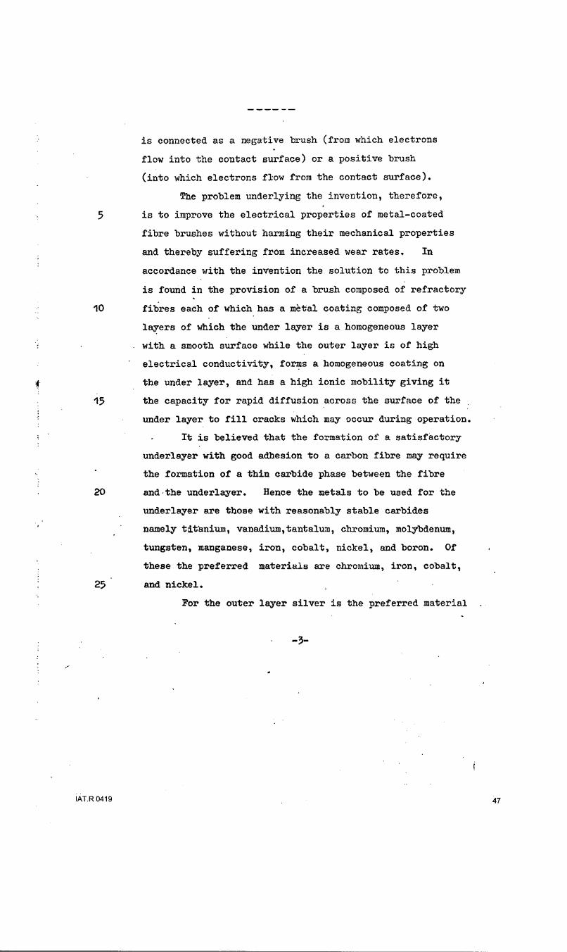
is connected as a negative brush (from which electrons
flow into the contact surface) or a positive brush
(into which electrons flow from the contact surface).
The problem underlying the invention, therefore,
5 is to improve the electrical properties of metal-coated
fibre brushes without harming their mechanical properties
and thereby suffering from increased wear rates. In
accordance with the invention the solution to this problem
is found in the provision of a brush composed of refractory
10 fibres each of which has a mttal coating composed of two
layers of which the under layer is a homogeneous layer
with a smooth surface while the outer layer is of high
electrical conductivity, forms a homogeneous coating on
f the under layer, and has a high ionic mobility giving it
15 the capacity for rapid diffusion across the surface of the
under layer to fill cracks which may occur during operation.
It is believed that the formation of a satisfactory
underlayer with good adhesion to a carbon fibre may require
the formation of a thin carbide phase between the fibre
20 and-the underlayer. Hence the metals to be used for the
underlayer are those with reasonably stable carbides
namely titanium, vanadium,tantalum, chromium, molybdenum,
tungsten, manganese, iron, cobalt, nickel, and boron. Of
these the preferred materials are chromium, iron, cobalt,
25 and nickel.
For the outer layer silver is the preferred material
-3-
IAT.R 0419 47

because of its high electrical conductivity and its
resistance to oxidation. Gold also has suitable
properties but is unlikely to be used because of its
high cost. If the brushes are to be run in a reducing
atmosphere, thereby avoiding the risk of oxidation,
it is possible to use copper, aluminium, cadmium or zinc,
copper being preferred. It is also possible
to use an alloy of silver and copper.
With a two-layer coating it has proved possible,
10 for a coating of the same overall thickness, to obtain
higher conductivity, i.e. lower voltage drop, than is
possible with a single layer of either of the coating
materials. This voltage drop is less variable from
sample to sample and is less dependent on the direction of
current flow between the brush and the contact surface.
Moreover these results are obtained without any deterioration
in the wear rate, in fact at high current densities there
is even some reduction in the rate of wear, perhaps
resulting from improved adhesion of the outer layer to the
20 under layer under conditions of high thermal stress as
compared with the adhesion of the material of the outer
layer to the surface of the fibre.
A variety of deposition processes can be used for
applying the two layers to the refractory fibres. The
preferred process is that of electro-plating and details
of how this may be applied are given in British Patent
-4-
IAT.R 0419 48

983561
Specifications Nos. 1,272,777 granted 30th August, 1972 and 1,309,252
granted 4th July, 1973, both to International Research & Development
Co. Ltd. Other processes available include pyrolysis of an organo-
metallic vapour, high vacuum evaporation, sputtering, and electroless
plating (that is chemical reduction of metallic salts).
By way of example one embodiment of this invention will
now be described in more detail and comparative information will be
given to show how this embodiment with a two-layer coating affords
A substantially better results than a single layer of either of the
10 coating materials separately. In this embodiment carbon fibres are
coated with an under layer of nickel and an outer layer of silver.
The carbon fibres used are high strength fibres of RAE
Type Il produced as described in British Patent Specification No.
1,110,971 granted to National Research Development Corporation and
published 24th April, 1968 by carbonization of polyacrylonitrile
fibres while holding them under tension. The average diameter of
the filaments is 7.5 v m. When such filaments are electroplated
with silver to give an average coating thickness, calculated in
terms of the amount of metal deposited per unit length of a bundle
20 consisting of as many as 104 fibres, of 1.0 u m the electrical
resistance is found to be 10 to 20 times higher than would be
expected with a uniform layer of this thickness. This is thought
to be due to the fact that the silver deposit is nodular and has
areas of poor
AIAT.R 0419 49

adhesion to the carbon fibre.
If such carbon fibres are electroplated with
nickel alone as a single layer a smoother, more
homogeneous deposit is formed and the electrical properties
5 are more consistent. There is better correlation between
the calculated layer thickness and the actual conductivity
but the overall voltage drop is generally higher than for
a silver layer.
If now a silver layer is electroplated onto a
S10 nickel layer there is a marked improvement in the electrical
and mechanical properties. Measurements of voltage drop
made with brushes running at a speed of 35m/sec on a silver-
plated slip ring with a current density of 500 KA/m 2 are
given in the following table for the various types of brush
15 Fibre coating Positive Brush Negative Brush
Nickel 1.5 0.40
Silver 1.2 0.25
Silver on nickel 0.20 0.15
The average coating thickness, as calculated from
20 the weight of material applied, was approximately 1p m for
the silver layer-alone, 0.7?m for the nickel layer alone,
and 0.5 1m of silver over O.7Pm of nickel.
In the case of a nickel-coated-positive brush the
initial voltage drop was similar to that of a negative
25 brush but within a few seconds of commencing operation it
rose to the higher value given in the table.
-6-
IAT.R 0419 50

983561
It will be seen from the table that in addition
to the low value of voltage drop obtained for a negative
brush with a two-layer coating there is a very important
improvement in the voltage drop for a positive brush so
5 that the performance of the brush is largely independent of
the direction of current flow.
A silver layer applied directly to the carbon fibre
by electro-plating from an alkali cyanide bath is nodular
and shows areas of poor adhesion where the material will
10 readily flake off under mechanical stress. It is believed
that the unevenness of the deposit and its lack of adhesion
are responsible for the fact that the resistance per unit
length is 10 to 20 times higher than would be expected
from the calculated average layer thickness. A nickel
15 layer plated from an acid bath gives a more smooth and
homogeneous layer which despite the presence of longitudinal
cracks showed little tendency to flake off. The correlation
between resistance and calculated layer thickness was better
than with silver.
20 When silver is plated onto a smooth nickel under
layer a higher nucleation density is obtained so that fewer
nodules are produced and the adhesion of the silver is
improved. The electrical resistance is close to that
expected from the calculated thickness, indicating that a
25 uniform homogeneous coating has been obtained. There is
little evidence of cracking in the layers. It appears,
-'0-
IAT.R 0419 .... ... """ ""51

983561
therefore, that the silver layer, in addition to reducing
the overall resistance along the coated fibre, improves
.the physical properties in three respects. Firstly,
being a softer material, it fills in and cements together
5 any cracks which are present in the nickel layer and thus
helps to maintain electrical contact between the nickel
and the fibre. Secondly it provides a source of mobile
ions to diffuse into cracks formed in the nickel during
operation, which again helps to maintain the electrical
10 performance of the layer. Thirdly it reduces thermal
gradients in the coating and thereby minimises stresses
due to differential expansion.
The basic requirements for the materials of the two
layers are as follows:-
15 First Layer: high nucleation density on carbon
fibre, preferably with some mechanism in the plat~ng process,
to limit the growth of large nodules. In other words, the
ability to form thin homogeneous layers with smooth surfaces.
Such layers may be internally stressed, and may tend to crack.
20 Second Layer: high nucleation density on first
material, givinghomogeneous layer. As plated, the material
should have little internal stress, and should be of a
thickness and resistivity appropriate to the application
envisaged. In addition, the material should be capable
25 of rapid surface diffusion, giving the ability to seal
major defects occuring in the underlayer during brush
operation.
-8-
IAT.R 0419 52

It may be advantageous in some cases to have a
coating composed of more than two layers with the
electrical and mechanical properties graded from the
inside layer to the outside layer.
-- 9-
IAT.R 0419 53

SUBSTITUTE
REMPLACEMENT
SECTION is not Present
Cette Section est Absente
IAT.R 0419 54
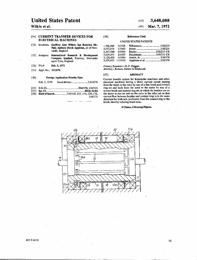
United States Patent [,51 3,648,088Wilkin et al. [451 Mar. 7, 1972
[54] CURRENT TRANSFER DEVICES FOR [56] References CitedELECTRICAL MACHINES UNITED STATES PATENTS
[72] Inventors: Geoffrey Alan Wilkin; Ian Roderick Mc- 1,706,369 3/1929 Williamson ............................ 310/219Nab; Anthony Derek Appleton, all of New- 3,073,979 1/1963 Potter .................................... 310/231castle, England 2,347,590 4/1944 Binder ............................. 310/231 UX
[73] Assignee: International Research & Development 2,629,075 2/1953 Deschmann ..................... 310/231 UXCompany Limited, Fossway, Newcastle 3,128,402 4/1964 Amick, Jr .............................. 310/178
upon Tyne, England 3,539,852 11/1970 Appleton et al ....................... 310/178
[22] Filed: Feb. 5, 1971 Primary Examiner-D. F. Duggan
[21] Appt. No.: 112,876 Attorney-Kemon, Palmer & Estabrook
[57] ABSTRACT[30] Foreign Application Priority Data Current transfer system for homopolar machines and other
Feb. 5, 1970 Great Britain ........................ 5,643/70 electrical machines having a direct current circuit passingfrom the stator to the rotor by way of a first brush and contact
[52] U.S.CI ............................................... 310/178, 310/219 ring set and back from the rotor to the stator by way of a[51] Int. CI ......................................................... H02k 31/02 second brush and contact ring set, in which the brushes are on[581 Field of Search .................. 310/138, 231,219, 239, 178, the stator in one set and on the rotor in the other set so that
310/175 current flow between brushes and contact rings is in the samedirection for both sets, preferably from the contact ring to thebrush, thereby reducing brush wear.
6 Claims, 2 Drawing Figures
1TR010 175
)6a. 191 55

Patented March 7, 1972 3,648,0882 Sheets-Sheet I
IAT.R 0419 56

Patend March 7, 1972 3,648,0882 Sheets-Sheet 2
Fio. 2.
22 2
2022 -- 0
24_ 36368
3"1• _-32
IAT.R 0419 57

3,648,0881 2
CURRENT TRANSFER DEVICES FOR ELECTRICAL periphery conducting paths 15 formed by a plurality of in-MACHINES dividual conductors extending axially of the rotor 13. Alterna-
tively the rotor may carry a single conducting path consistingThis invention relates to current transfer in dynamo-electric of a continuous cylindrical sleeve on the surface of the rotor.
machines and is concerned particularly with machines in 5 At the ends of the conducting paths 15 on the rotor 13 therewhich current transfer takes place between brushes of electri- are current transfer devices 16 and 17 which serve to transfercally conducting material and contact surfaces of electrically current between the stator 10 and the conducting paths on theconducting material, there being relative rotation between the rotor 13. The current transfer device 16 comprises a pluralitybrushes and the contact surfaces, and the direction of current of carbon brushes 16a mounted on the rotor for rotation withflow between each brush and the associated contact surface 10 the rotor. The brushes 16a, each of which is composed of anremains constant. Typical of such machines are homopolar assembly of carbon fibers, can form a complete ring extendingmachines and synchronous electrical machines where, for ex- substantially continuously around the periphery of the rotor.ample, a direct current is fed through brushes into slip rings on The current transfer device 16 also comprises a frustoconicala rotor to provide excitation for a field winding mounted onthe rotor. I5 contact ring !6b which is mounted on the stator I0 between
the probls pthe parts I la and 1 lb of the field coil. The contact ring 16b isThe problems presented by brush wear and electrical losses biassed in the direction of the arrows A by a spring (not
on homopolar machines are acute because of the high cur- shown) so that brush wear is compensated for by axial move-rents which arc transmitted by the current transfer brushes. ment of the contact ring.Brush wear can also be a problem in large turbogeneratorswhere high currents need to be transferred at high rotational 20 The current transfer device 17 comprises a number of
speeds, brushes 17a mounted on the stator 10 and engaging a contact
In accordance with the present invention there'is provided a surface composed of a ring of contact segments 17b on the ro-
dynamoelectric machine comprising a rotor and a stator, a tor. Each of the contact segments 17b is connected to one end
direct current circuit extending from the stator to the rotor of a rotor conductor 15, whose other end is connected to one
and back to the stator, first current transfer means in the said 25 of the brushes 16a. The contact segments 17b are mutually in-
circuit for conveying current from the stator to the rotor, and sulated from one another. The brushes 17a are located
second current transfer means in said circuit for conveying between the two parts 12a and 12b of the field coil on the sta-
current from the rotor to the stator, each of the current tor 10.
transfer means comprising at least one brush and a contact The brushes 17a on the stator are connected by leads 18 to
surface movable relative to and cooperating with said brush 30 one terminal of the machine while the contact ring 16b is con-
for the transfer of current therebetween, the brush of the first nected by leads 19 to the other terminal of the machine. Cur-
transfer means and the contact surface of the second transfer rent flow thus proceeds from this other terminal through the
means being mounted on the rotor and the brush of the second leads 19 to the contact ring 16b and thence into the brushes
transfer means and the contact surface of the first transfer 35 16a. It then flows through the rotor conductors to the contactmeans being mounted on the stator, whereby the direction of segments 17b and from them into the brushes 17a and by waycurrent flow between the brush and the contact surface is the of leads 18 to the external circuit. In each of the current
same for each of the current transfer means. transfer devices the current flow is from the contact surfacePreferably the direction of current flow is from the contact into the brush and it is found that the electrical losses and
surface into the brush, that is electrons pass from the brush to 40 brush wear rate are considerably improved over arrangementsthe contact surface. in which the direction of current flow is different in each cur-
It is found that this arrangement of the brushes and contact rent transfer device.surfaces results in reduced brush wear. In an alternative arrangement the direction of current flow
The contact surfaces may be in the form of continuous slip is reversed but again the direction of flow is the same in bothrings or may be composed of individual mutually insulated 45 current transfer devices. The arrangement is applicable tosegments. The brushes may be of carbon and may be arranged machines acting as motors or generators.individually around a contact surface or form a substantially The contact segments 17b are shown as presenting a cylin-continuous ring. The brushes may be composed of arrays of drical contact surface and the brushes 17a are biassed againstcarbon fibers either in the form of individual brushes or as a this surface in a radial direction in conventional manner. It iscontinuous ring. 50 of course possible to use a frustoconical contact surface in the
To allow for wear the contact surfaces may be frustoconical transfer device 17 as in the device 16 and to bias the brushesand be urged under a spring force in a direction transverse to axially against the contact surface. Whereas the brushes 16athe contact face of the brush, the movement being in a and 17a are composed of carbon fibers in the embodimentdirection such that any gap forming between the brush and the shown, and these fibers can be metal coated, it is also possiblesurface is taken up. 55 to use conventional carbon block brushes.
The invention will now be described in more detail with the FIG. 2 shows the application of the invention to aaid of examples illustrated in the accompanying drawings, in homopolar machine with a disc rotor. The machine has a sta-which:
FIG. h isa section of a homopolar electrical machine having tor 20 which supports a superconducting field coil 21. A rotoraIG. drumtypectin rot an current traneria mean ine haccornce 6support disc 22 is carried by a shaft 23 which is mounted in
a drum type rotor and current transfer means in accordance 60 bearings (not shown) in the stator. On either side of the sup-with the invention, and
FIG. 2 is a section of a homopolar machine with a disc rotor port disc 22 are conducting disc 24 and 25, for example of
and current transfer means in accordance with the invention. copper, which are secured by studs 26. The outer periphery of
The homopolar electrical machine shown in FIG. 1 has a each of the discs 24 and 25 has a flange which presents a con-
stator 10 which carries a first field coil composed of parts 1la 65 tact surface 24a and 25a, respectively, of frustoconical form
and 111b and a second field coil composed of parts 12a and towards the rotor axis. These contact surfaces 24a and 25a are
12b. The field coils can be of superconducting material in engaged by stationary brushes 27 and 28, respectively, which
which case they are enclosed in a cryogenic envelope in a con- are mounted on the stator structure 20 and are connected to
ventional manner to maintain the low operating temperature the external circuit by conductors 29 and 30, respectively.which is required. In the case of superconducting coils no 70 The inner regions of the discs 24 and 25 have cylindrical ex-
magnetic core is required on the stator. Alternatively the field tensions 31 and 32, respectively, which house brushes 33 andcoils can be of normal conducting material and in this case are 34, respectively. The brushes 33 engage a fixed contact ringdisposed in a magnetic core on the stator 10 in conventional 35 which is connected to the external circuit by conductorsmanner. The machine has a drum motor 13 which rotates 36. The brushes 34 engage a fixed contact ring 37 which iswithin the stator on a shaft 14 and which carries on its 75 connected to the external circuit by conductor 38.
IAT.R 0419 58

3,648,0883 4
The two discs 24 and 25 are connected in separate circuits through slip-rings to a rotor winding.each of which includes two current transfer devices, one for Whilst carbon brushes have been described other brushtransferring current from the stator to the rotor and one for materials can be used such as metal brushes, composite metal-transferring the current from the rotor to the stator and in graphite brushes or metal such as silver with molybdenumeach circuit the direction of current flow is the same for each 5 disulphide.current transfer device. Thus one circuit runs from the contact We claim:ring 35 to the brushes 33, through the disc 24 to the contact 1, A dynamoelectric machine comprising a rotor and a sta-surface 24a and thence to the brushes 27. The other circuit is tor, a direct current circuit extending from the stator to thefrom the contact ring 37 to the brushes 34, through the disc 25 rotor and back to the stator, first current transfer means in theto the contact surface 25a and thence to the brushes 28. 10 said circuit for conveying current from the stator to the rotor,
Each of the brushes 33 and 34 which rotate with the rotor and second current transfer means in said circuit for convey-may be a continuous ring of carbon in solid or fiber form or ing current from the rotor to the stator, each of the currentmay be composed of several discrete brushes. The contact transfer means comprising at least one brush and a contactrings 35 and 37 may be urged in an axial direction by springs surface movable relative to and cooperating with said brush(not shown) to compensate for brush wear. 15 for the transfer of current therebetween, the brush of the first
The attitude of the interface between each set of brushes transfer means and the contact surface of the second transferand the associated contact surface is preferably arranged to means being mounted on the rotor and the brush of the secondfollow the direction of the magnetic field lines in that region in transfer means and the contact surface of the first transferorder to avoid a voltage being developed across the interface, means being mounted on the stator, whereby the direction of
If the discs 24 and 25 are segmented as described in our 20 current flow between the brush and the contact surface is theU.S. Pat. No. 3,497,739, each rotor disc will be divided up same for each of the current transfer means.into separate mutually insulated radial conducting paths each 2. A dynamoelectric machine as claimed in claim 1 whereinconnected to a separate insulated segment on the outer flange the direction of current flow in the direct current circuit isand on the inner cylindrical extension. The brushes will be dis- from the contact surface into the brush.crete brushes spaced by at least one segment width around the 25 3. A dynamoelectric machine as claimed in claim t in whichouter flange and inner cylindrical extension. The electrical each of the contact surfaces comprises a plurality of mutuallyconnections will be such as to connect selected conducting insulated electrically conductive segments.paths in series as the rotor rotates. The contact rings 35 and 37 4. A dynamoelectric machine as claimed in claim 1 in whichwvill also be segmented with insulation between the conducting each brush comprises a block of carbon.segments. 30 5. A dynamoelectric machine as claimed in claim I in which
The brushes may be held in position by conventional brush each brush comprises an array of carbon fibers.holders or if fiber brushes are used the arrays or bundles of 6. A dynamoelectric machine as claimed in claim I in whichfibers can be held in crimped tubes, the contact surfaces are frustoconical and are biassed against
Whilst the invention has been described with particular the brushes by force applying means acting in a directionreference to homopolar machines it can also be applied to 35 transverse to the brushes.synchronous machines where direct current is transferred * * * * *
40
45
50
55
60
65
70
75IAT.R 0419 59

United States Patent [19] i1 3,821,024Wilkin et al. [453 June 28, 1974
[541 CURRENT TRANSFER BRUSHER 2,300,503 11/1942 Hamister ............................. 310/2483,270,306 8/1966 Burski ................................. 310/248[751 Inventors: Geoffrey Alan Wilbin; Ian Roderick 3,382,387 5/1968 Marshall ............................ 310/248
MeNab, both of 3,459,583 8/1969 Rubisch .............................. 117/228Newcastle-upon-Tyne, England 3,476,586 11/1969 Valtchev ............................. 117/228
[73] Assignee: International Research & 3,525,006 8/1970 Parr .................................... 310/252Development Company Limited, 3,691,421 9/1972 Decker .............................. 117/217
Fossway, England Primary Examiner-R. Skudy[221 Filed: Feb. 23, 1973 Attorney, Agent, or Firmr-Kemon, Palmer &
[211 Appl. No.: 335,331 Estabrook
[30] Foreign Application Priority Data [57] ABSTRACTFeb. 29, 1972 Great Britain ...................... 9256/72 A current transfer brush is composed of refractory
fibres, preferably high strength carbon fibres, with a[52] U.S. C1 ................... 117/217, 117/228, 310/252 metallic coating on the fibres which is composed of an[51] Int. CI ........... I .................... ý. C23b 5/50 under layer of a first metal and an over layer of a sec-[58] Field of Search .... 310/219, 231, 245, 248-253; ond metal. The over layer is of a highly conductive
117/217, 228, 71 material such as silver and the under layer which im-proves coherence and adhesion of the over layer and
[56] References Cited thereby produces a very low brush voltage drop, is ofUNITED STATES PATENTS a material such as nickel.
722,606 3/1903 Motsinger .......................... 310/248 7 Claims, 2 Drawing Figures
66
IAT. 04194-2'
iAT.R 0419 6

PATENTEDJuN 28 1974 3,821,024
F-/o.1
Fi-4o.2
IAT.R 0419 61

3,821,0241 2
CURRENT TRANSFER BRUSHER with a single layer of either of the coating materials.This voltage drop is less variable from sample to sample
The present invention relates to current transfer and is less dependent on the direction of current flowbrushes consisting of refractory fibres, such as carbon between the brush and the contact surface. Moreoverfibres, coated with an eletrically-conductive metallic 5 these results are obtained without any deterioration inlayer. the wear rate, in fact at high current densities there is
Such brushes form the subject of our British Pat. No. even some reduction in the rate of wear, perhaps result-1,191,234, French Pat. No. 70,30073 and U.S. Pat. No. ing from improved adhesion of the outer layer to the3,668,451 and are particularly valuable for use in ho- under layer under conditions of high thermal stress asmopolar machines where high speeds of rotation and 10 compared with the adhesion of the material of thelarge currents call for brushes which exhibit a low rate outer layer to the surface of the fibre.of wear when rubbing against a rapidly moving contact A variety of deposition processes can be used for ap-surface and which have high electrical conductivity. In plying the two layers to the refractory fibres. The pre-these prior brushes the carbon fibres which are em- ferred process is that of electro-plating and details ofployed have very good mechanical properties because 15 how this may be applied are given in our British Pat.of their special method of production and they provide specifications Nos. 1,272,777 and 1,309,252. Othersupport for the layer of electrically conductive metal, processes available include pyrolysis of an organome-such as silver, which probably carries most of the cur- tallic vapour, high vacuum evaporation, sputtering, andrent. The thickness of the layer is limited because it is electroless plating (that is chemical reduction of metal-essential to maintain the flexibility of the fibre in order 20 lic salts).to give satisfactory wear rates. Therefore the electrical By way of example one embodiment of this inventionconductivity cannot be increased simply by using a will now be described in more detail and comparativethicker coating. Unfortunately it is found in practice information will be given to show how this embodimentthat a layer of a particular thickness, calculated from with a two-layer coating affords substantially better re-the weight deposited per unit area, gives a conductivity 25 suits than a single layer of either of the coating materi-lower by a factor of 10 or more than the expected als separately. In' this embodiment carbon fibres arevalue. Moreover the conductivity, and thus the voltage coated with an under layer of nickel and an outer layerdrop at the brush, varies from one sample to another of silver.and is different according to whether the brush is con- The carbon fibres used are high strength fibres ofnected as a negative brush (from which electrons flow 30 RAE Type II produced as described in British Pat.into the contact surface) or a positive brush (into specification No. 1,110,971 by carbonization of poly-which electrons flow from the contact surface). acrylonitrile fibres while holding them under tension.
The problem underlying the invention, therefore, is The average diameter of the filamentsis 7.5 A. hi. Whento improve the electrical properties of metal-coated such filaments are electroplated with silver to give anfibre brushes without harming their mechanical proper- 35 average coating thickness, calculated in terms of theties and thereby suffering from increased wear rates. In amount of metal deposited per unit length of a tow con-accordance with the invention the solution to this prob- sisting of as many as 101 fibres, of 1.0 p. m the electricallem is found in the provision of a brush composed of resistance is found to be 10 to 20 times higher thanrefractory fibres each of which has a metal coating would be expected with a uniform layer of this thick-composed of two layers of which the under layer is a 40 ness. This is thought to be due to the fact that the silverhomogeneous layer with a smooth surface while the deposit is nodular and has areas of poor adhesion to theouter layer is of high electrical conductivity, forms a carbon fibre.homogeneous coating on the under layer, and has a If such carbon fibres are electroplated with nickelhigh ionic mobility giving it the capacity for rapid diffu- alone as a single layer a smoother, more homogeneoussion across the surface of the under layer to fill cracks 45 deposit is formed and the electrical properties are morewhich may occur during operation. consistent. There is better correlation between the cal-
It is believed that the formation of a satisfactory un- culated layer thickness and the actual conductivity butderlayer with good adhesion to a carbon fibre may re- the overall voltage drop is generally higher than for aquire the formation of a thin carbide phase between the silver layer.fibre and the underlayer. Hence the metals to be used 50 • If now a silver layer is electroplated onto a nickelfor the underlayer are those with reasonably stable car- layer there is a marked improvement in the electricalbides namely titanium, vanadium,tantalum, chromium, and mechanical properties. Measurements of voltagemolybdenum, tungsten, manganese, iron, cobalt, drop made with brushes running at a speed of 35m/sec
nickel, and boron. Of these the preferred materials are on a silver-plated slip ring with a current density of 500chromium, iron, cobalt, and nickel. 55 KA/m 2 are given in the following table for the various
For the outer layer silver is the preferred material be- types of brushcause of its high electrical conductivity and its resis-tance to oxidation. Gold also has suitable properties Fiber coating Positive Brush Negative Brush
but is unlikely to be used because of its high cost. If the 60brushes are to be run in a reducing atmosphere, Nickel 1.5 0.40
Silver 1.2 0.25thereby avoiding the risk of oxidation, it is possible to Silver on nickel 0.20 0.15use copper, aluminium, cadmium, zinc or lead, copperbeing preferred. It is also possible to use an alloy of sil-ver and copper. 65 The average coating thickness, as calculated from the
With a two-layer coating it has proved possible, for weight of material applied, was approximately lI m fora coating of the same overall thickness, to obtain higher the silver layer alone, 0.7Am for the nickel layer alone, 62
IAxRdtoicvity, i.e., lower voltage drop, than is possible and 0.51L m of silver over 0.71A m of nickel.
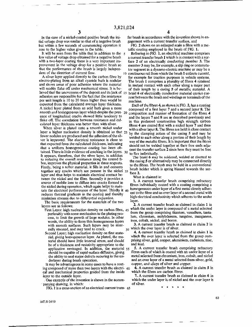
3,821,0243 4In the case of a nickel-coated positive brush the ini- fer brush in accordance with the invention shown in en-
tial voltage drop was similar to that of a negative brush gagement with a current transfer surface, andbut within a few seconds of commencing operation it FIG. 2 shows on an enlarged scale a fibre with a me-rose to the higher value given in the table. tallic coating employed in the brush of FIG. 1.
It will be seen from the table that in addition to the 5 Referring to FIG. 1, an electrical machine compriseslow value of voltage drop obtained for a negative brush a current transfer brush I which is in contact with a sur-with a two-layer coating there is a very important im- face 2 of an electrically conducting member 3. Theprovement in the voltage drop for a positive brush so member 3 may be, for example, a slip ring or commuta-that the performance of the brush is largely indepen- tor segment in a dynamo-electric machine or may be adent of the direction of current flow. 10 continuous rail from which the brush 1 collects current,
A silver layer applied directly to the carbon fibre by for example for traction purposes in vehicle systems.electro-plating from an alkali cyanide bath is nodular The brush 1 comprises a plurality of fibres 4 retainedand shows areas of poor adhesion where the material in mutual contact with each other along a major partwill readily flake off under mechanical stress. It is be- of their length by a casing 5 of metallic material. Alieved that the unevenness of the deposit and its lack of 15 braid 6 of electrically conductive material carries cur-adhesion are responsible for the fact that the resistance rent between the brush and windings or terminals of theper unit length is 10 to 20 times higher than would be machine.expected from the calculated average layer thickness. Each of the fibres 4, as shown in FIG. 2, has a coatingA nickel layer plated from an acid bath gives a more composed of a first layer 7 and a second layer 8. Thesmooth and homogeneous layer which despite the pres- 20 composition and manner of formation of the fibres 4ence of longitudinal cracks showed little tendency to and the layers 7 and 8 are as described previously andflake off. The correlation between resistance and cal- in this preferred construction high strength carbonculated layer thickness was better than with silver, fibres 4 are coated first with a nickel layer 7 and then
When silver is plated onto a smooth nickel under with a silver layer 8. The fibres are held in close contactlayer a higher nucleation density is obtained so that 25 by the clamping action of the casing 5 and may befewer nodules are produced and the adhesion of the sil- welded to each other along a portion of their length byver is improved. The electrical resistance is close to way of the metallic fibres. It is important that the fibresthat expected from the calculated thickness; indicating should not be welded together at their free ends adja-that a uniform homogeneous coating has been ob- tent the transfer surface 2 since here they must be freetained. There is little evidence of cracking in the layers. 30 to flex individually.It appears, therefore, that the silver layer, in addition The braid 6 may be soldered, welded or rivetted toto reducing the overall resistance along the coated fi- the casing 5 or alternatively may be connected directlybre, improves the physical properties in three respects. to the fibres. The brush may be held in a conventionalFirstly, being a softer material, it fills in and cements brush may beaseld inwarconventinatogeheranycraks hic arepreentin he ickl ~ brush holder which is spring biassed towards the sur-together any cracks which are present in the nickel 35fae2layer and thus helps to maintain electrical contact be- fac 2.tween the nickel and the fibre. Secondly it provides a What is claimed is:source of mobile ions to diffuse into cracks formed in 1. A current transfer brush comprising refractorythe nickel during operation, which again helps to main- fibres individually coated with a coating comprising a
tain the electrical performance of the layer. Thirdly it 40 homogeneous under layer of a first metal closely adher-
reduces thermal gradients in the coating and thereby ent to the fibre and an over layer of a second metal with
minimises stresses due to differential expansion. high electrical conductivity which adheres to the under
The basic requirements for the materials of the two layer.layers are as follows: 2. A current transfer brush as claimed in claim 1 in
First Layer: high nucleation density on carbon fibre, 45 which the under layer is composed of a metal selected
preferably with some mechanism in the plating pro- from the group comprising titanium, vanadium, tanta-cess, to limit the growth of large nodules, In other lum, chromium, molybdenum, tungsten, manganese,words, the ability to form thin homogeneous layers iron, cobalt, nickel, and boron.with smooth surfaces. Such layers may be inter- 3. A current transfer brush as claimed in claim 2 innally stressed, and may tend to crack. 50 which the over layer is of silver.
Second Layer: high nucleation density on first mate- 4. A current transfer brush as claimed in claim 1 inrial, giving homogeneous layer. As plated, the ma- which the over layer is selected from the group com-terial should have little internal stress, and should prising silver, gold, copper, aluminium, cadmium, zinc,be of a thickness and resistivity appropriate to the and lead.application envisaged. In addition, the material s5 5. A current transfer brush comprising refractoryshould be capable of rapid surface diffusion, giving fibres each of which is coated with an under layer of athe ability to seal major defects occuring in the un- metal selected from chromium, iron, cobalt, and nickelderlayer during brush operation. and an over layer of a metal selected from silver, gold,
It may be advantageous in some cases to have a coat- copper, and alloys of silver and copper.ing composed of more than two layers with the electri- 60 6. A current transfer brush as claimed in claim 5 incal and mechanical properties graded from the inside which the fibres are carbon fibres.layer to the outside layer. 7. A current transfer brush as claimed in claim 6 inSOne example of the invention is shown in the accom- which the under layer is of nickel and the over layer ispanying drawing, in which: of silver.
FIG. l is a cross-section of an electrical current trans- 65 * ' * * *
63IAT.R 0419
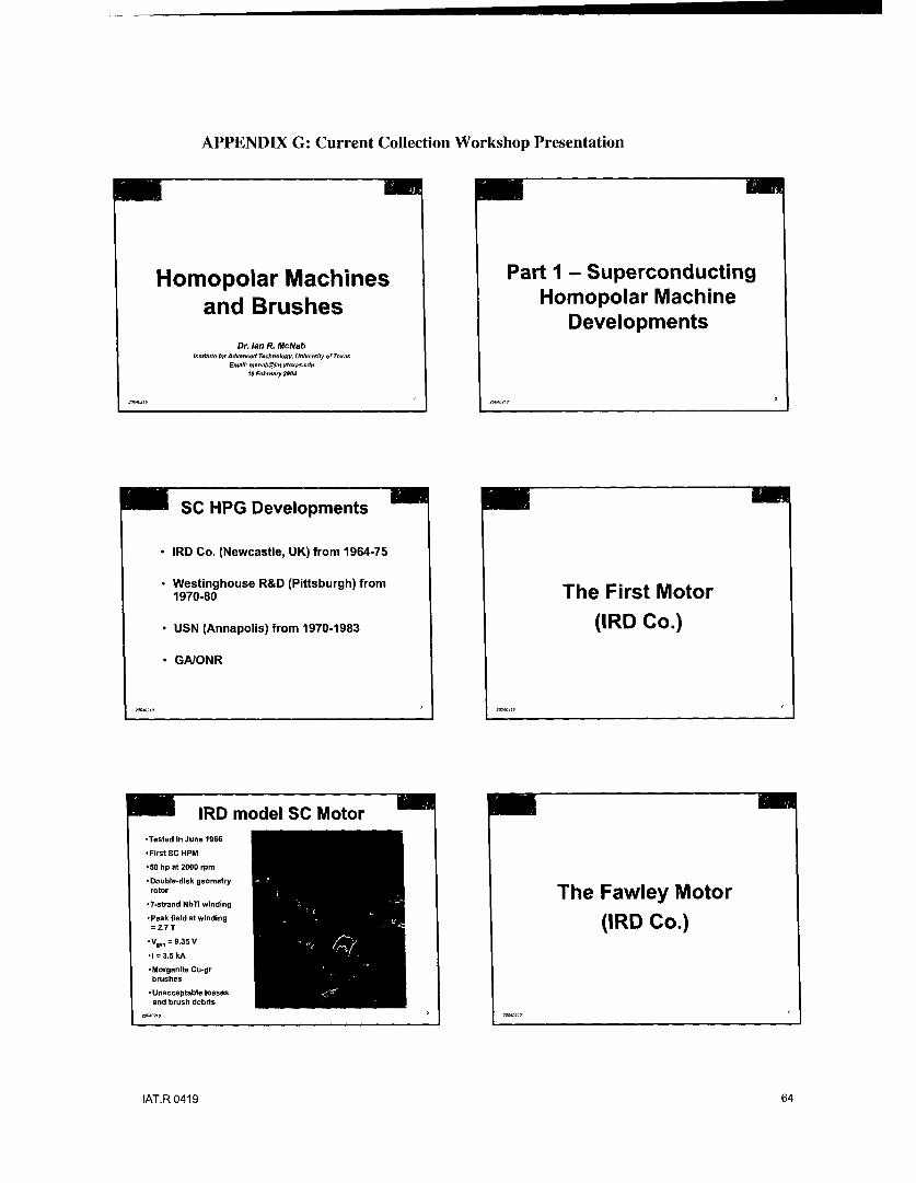
APPENDIX G: Current Collection Workshop Presentation
Homopolar Machines Part I - Superconducting
and Brushes Homopolar MachineDevelopments
Dr. Ian R McNabtn&Hnfl for Advaned Technology, University of Texas
EmaH: [email protected] February 2004
7 sc HPG Developments
* IRD Co. (Newcastle, UK) from 1964-75
* Westinghouse R&D (Pittsburgh) from
1970-80 The First Motor
* USN (Annapolis) from 1970-1983 (IRD Co.)
* GA1ONR
l ~IRD model SC Motor1
-Tested in June 1966
-First SC HPM
*50 hp at 2000 rpm
* Double-disk geometryrotor The Fawley Motor*7-strand NbTi winding
-Peak field at windingm 2.7 T (IRD Co.)"*V.n = 9.35 V
•1 = 3.5 kA
*Morganite Cu.grbrushes
-Unacceptable lossesand brush debris
IAT.R 0419 64
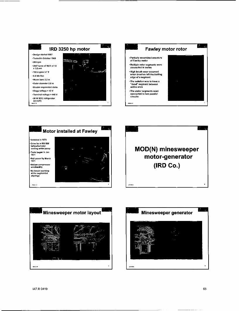
IRD 3250 hp motor Fawley motor rotor-Design started 1967
*Tested in October 1969 -Partially assembled armature
• 200 rpm of Fawley motor
•3947 turns of NbTi of 10 -Multiple rotor segments were
x 1.8 mm connected in series
* 725 A gave 3.7 T -High brush wear occurred
*6.6 Wb flux when brushes left the trailing
edge of a segment
*The solution was to have a-Outer diameter 2.8 m "dead" segment between
-Double segmented disks active ones
- Stage voltage = 42 V -The stator segments were
-Terminal voltage = 440 V connected in two parallelcircuits
50 W gOC refrigerator
(at 4.4K)
Motor installed at Fawley
installed in 1970
SDrive for a 500 MWturboaltematorcooling water pump
-Tess bean i JanMOD(N) minesweeper* Tests began in Jan
1971
-Full power by March motor-generator1971
- Helium compressorunreliability (IR D C o .)
-No brush sparkingat the segmentedsliprings
Minesweeper motor layout Minesweeper generator
IAT.R 0419 65

7 Coil assembly into stator Minesweeper generator rotor
Assembly area- 1 7! ýAssembly area - 2
Generator cross-section
Rutherford generator(IRD Co.)
IAT.R 0419 66

Rutherford rotor Generator & drive motor
Rutherford generator CF brushes Lessons learned
Observations:
Homopolar machines are basically simple and robustThey are intrinsically low voltage (V.), high current (I.)machinesMulti-staging can improve the terminal characteristics: nV.and IJnThere is no armature reaction on the field windingsAll the machine power goes through the brush/sliprinointerface
Lesson:* The "brush" designer has to be an integral part of the
machine design process - brushes cannot just be insertedafter the machine is built
Constant force ("tensator") springs were used
Brush Features A few other things .......
What we want (and why): Current sharingLow electrical contact drop (losses) 7 Brush contact stability
* Low friction coefficient (losses) B r an d s t eriity* Long brush life (minimal maintenance & cost) Slipring wear and deterioration* Long slipring life (no machine refurbishment) Slipring grooves* Minimal necessary auxiliaries (cost & complexity) Rotor reversal for a motor
Atmosphere controlWhat we don't want (and why): Debris removal* Brush (& slipring) wear debris (machine failure & Operating conditions (speed,
maintenance) current density, etc)
IAT.R 0419 67

Brush selection Liquid metals - 1
• Machine designers should assess all options and Mercury
choose the most appropriate for their application - First used by Faraday in 1830'sBrush choices: - High density causes high viscous losses
- Toxicity makes it unacceptable- Conventional metal-graphi~te grades • NaK (and Na)
- Fiber brushesCarbon fibers - Used by Allis Chalmers in 1960's HPGs, ANU HPG in
* Metal-plated carbon fibers 1970's, by Westinghouse and by USN Annapolis* Metal fibers - Reactive with water and forms explosive superoxides
- Metal foil - Accidents have happened- Liquid metals - Continuous purification loops needed
- Annapolis porous brush approach seemed best- Not a good choice for a ship main propulsion system
Liquid metals - 2 Conventional brushes
Low melting point elements and alloys Initial high current tests done with copper-- Indium, tin, gallium, lead graphite brushes (Morganite grade CMIS)- Intermediate density gives moderate viscous losses ° Choice was based on experience at ANU- Strong tendency to oxidize demands atmospheric homopolar generator in Canberra
control Brush life was an issue- Oxidation cause high viscosity and even solidification Ushlife wa s a se- An~napolis are the experts in recent times •Utility turboalternators used pure graphite
brushes for high speed long life operation - but
My conclusion -liquid metal solutions are not yet contact voltage drops were too high for HPs
attractive Alternatives sought
Early days
7 First suggestion of possibility of using carbonfibers as a brush made by Sam Bolshaw(Scientific Advisor to MOD-N) in - 1967
Carbon fiber brush • Idea was that flexible carbon fibers (just thenbeing produced) would provide a stable and large
development contact area with the slipring* Initial brushes made and tested by IRD
(IRD Co.) Performance improved with timeEvaluation showed that slipring wear debris wasbeing embedded in the brush and providedincreased contactI RD decided to try to make metallic plated fibers
IAT.R 0419 68

Carbon fiber plating bath Plated carbon fibers
*A wet electroplating processwas developed
*Delivered tows contained -The products created
10,000 fibers were evaluated formacroscopic and
* Fibers were unrolled off microscopic qualityshipping drums and passedthrough a multistage bath -Samples included silver-process plated carbon fibers
* Steps included: -Typical fiber diameter -
* spreading the fbers 7 microns* removing surface treatments* sensitizing the surface Typical plating* laying down an initial coating* plating thickness - 1 micron
* drying* winding onto drums
Single fiber brush Brush testing
- Tests were undertaken
* In the manufacturing process, over a wide range of
multilayers of fibers were laid conditions:
up in a jig -speed
* Required lengths were cut up - current density
* Early fiber brushes were - brush plating
crimped - slipring material
* Later (lower cost) brush backs
were plasma sprayed and - atmosphere
soldered - paralleled brushes
* This assembly was then Generator operation more
soldered to a backing plate that stressing (much higherhad electrical connections speed) than motor opn.attached
Multiple test rigs used Test data example
Lo ung duration (t00thr.) multiple brush test
* Silver-plated carbonfibers ona silver 3 -sufpring (probably)
* Reducing humidifiedatmosphere
Current density .increased (deliberatelyAtlduring test
* Data shows nominalfiber brush current i!density2
Slipring speed?(probably moderately M6 - in -.high)a• ••b
High speed enclosed tester Rn-rint brush t.,ser
IAT.R 0419 69
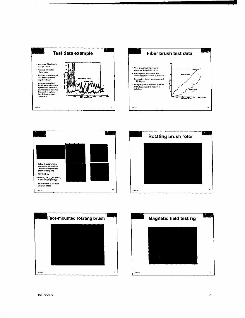
Test data example Fiber brush test data
* Measured fi~ber brushvoltage drops - Fiber brush wear rates were
* Positive brush has measured in the 5000 hr. test
higher rop Th negative brush wear was* Positive brush is much - remarkably low: 10 m r. in 5000 hr.
less stable thus the omnegstia brush the The positive brush wear was muche be
(x 20) higher* A servo-controlled Multiple approaches were pursue
brush wear adjustment Mw d
system was installed • to evaluate reasons and seekand helped to stabilize C.o)lutiosthe positive voltage -but differences stillremained - a.. ,
Rotating brush rotor
*Define M parameter toassess the effect of theInduced voltage on thebrush and slipring
•M=VTI2V.
(where Vr = Br,0
,VVL and V U= brush voltage drop)
* Recommend M - 0.1 forminimal effect
7 'Face-mounted rotating brush 7 Magnetic field test rig
IAT.R 0419 70

he Ultimate HPG Brush ? All-superconducting machine
* Concept:- Make brushes of superconducting wire
Run them in the cryogenic fluid (LN2 or LHe) -K* Idea first described in Westinghouse Patent Disclosure RES 75- 7-
274.13 June 1975 ouuVP roof of possibility: B.L. Blackford, et. al. showed that a wirecould remain superconducting while in sliding contact with aslipring (Cryogenics, Vol 4. May 1975. p. 94.
* Discussed at the International Current Collector Conference, UTAustin. 16-17 Nov 1987Big issue -will the frictional heat of sliding make the E'Qcontact go normal.
* Big advantage - the whole machine is superconducting, soall electrical losses are reduced and efficiency goes up
* Recommendation - ONR fund some experiments to try it IFrom: "Superconducting Brushes and Machines" by I.R. McNab presented at theInternational Current Collector Conference, University of Texas. 16-17 November 1987.
Multi-stage All-SC machine SummaryID eonls > Significant advances have occurred in EM Launch technology
g* ouglngl s understood and ovwrcome*advances In understandlng transltion am being made* barrellofethee wrmaans 0Issue7 stato-of-theart fast computing toots am being improved
> Pulsed Power developments are taking place: pulsed alternator modeling Is adoancing0 sItch technology Improvements being quarnifled
Ails EL.. -- " •. . hyrid electric vhicle modeling* power system slze remains an Issue
i System integration issues are starting to be addressed> Better definition of mission requirements is needed to drive
the technologyUJM • > Non-direct fire applications are also being evaluated
From: 'Superondutling Brushes and Machines" by Lit. McNab presented at the A. v. a ive ] t is suppr-in the.
Intermaonal Current Collector conference, Unloerolty of Texas. 16-17 November 1987. NatJionl - E. gun progra
IAT.R 0419 71