final publishable summary - cordis · 2015-03-22 · aristotel acpo-ga-2010-266073 final...
TRANSCRIPT

1 Dissemination level: public
FINAL PUBLISHABLE SUMMARY
Grant Agreement number: 266073
Project acronym: ARISTOTEL
Project title: AIRCRAFT and ROTORCRAFT PILOT COUPLINGS – TOOLS and TECHNIQUES FOR ALLEVIATION and DETECTION
Funding Scheme: Small or medium-scale focused research project
FP7-AAT-2010-RTD-1
Name, title and organisation of the scientific representative of the project's coordinator:
Prof. Marilena Pavel
Technische Universiteit Delft
Tel: +31 15 2785374
Fax: +31 15 2789564
E-mail: [email protected]
Project website address: http://www.aristotel-project.eu/

ARISTOTEL ACPO-GA-2010-266073 Final Publishable Summary
2 Dissemination level: public
TABLE OF CONTENTS
TABLE OF CONTENTS ............................................................................................ 2 EXECUTIVE SUMMARY ........................................................................................... 3 CONTEXT AND OBJECTIVES ................................................................................. 4
Aircraft and Rotorcraft Pilot Couplings (A/RPC) – unpreventable and dangerous for aviation safety ........................................................................................................ 4 Modern Flight Control Systems, a Critical Issue for Flight Safety of Modern Aircraft .............................................................................................................................. 4 Rotorcraft-Pilot Coupling (RPC), Significantly More Problematic for Safety than Aircraft-Pilot Coupling (APC) ................................................................................. 5 The Six Scientific and Technical Objectives and Their Relevance to the Call ........ 5 The Six Key Problems of the Project ..................................................................... 5
DESCRIPTION OF THE MAIN S&T RESULTS/FOREGROUNDS ............................ 8 Approach to A/RPCs in ARISTOTEL ..................................................................... 8 Defining A/RPCs .................................................................................................. 10 Past, Present and Future A/RPCs ....................................................................... 11 Past ..................................................................................................................... 11 Present ................................................................................................................ 12 Future .................................................................................................................. 13 Rigid body RPC Findings ..................................................................................... 15 Pilot Modelling for rigid body A/RPC - Boundary Avoidance Tracking (BAT) Pilot model................................................................................................................... 18 Prediction of rigid body RPC ................................................................................ 20 Aeroelastic A/RPC Findings ................................................................................. 22
POTENTIAL IMPACT AND THE MAIN DISSEMINATION ACTIVITIES AND EXPLOITATION OF RESULTS ............................................................................... 25
Project relevance to the FP7 goals ...................................................................... 25 Main project outputs dissemination and exploitation strategy ............................... 26

ARISTOTEL ACPO-GA-2010-266073 Final Publishable Summary
3 Dissemination level: public
EXECUTIVE SUMMARY
The ARISTOTEL project challenge consisted in ensuring aircraft safety and aimed to reduce the aircraft and rotorcraft accidents caused by a particularly unfavourable category of phenomena: aircraft-pilot-couplings and rotorcraft-pilot-couplings (A/RPCs). Generally, A/RPCs are defined as “inadvertent, sustained aircraft oscillations which are a consequence of an abnormal joint enterprise between the aircraft and the pilot”. Recent experiences show that modern designs are being confronted in an increasing degree with dangerous A/RPCs. The reason for this is that modern aircraft feature a significant level of automation in their flight-control-systems (FCS). FCS is generally intended to relieve pilot workload and allow operations in degraded weather and visibility conditions. Especially in the modern rotorcraft, there seem to be embedded tendencies predisposing the FCS system towards dangerous RPCs. As the level of automation is likely to increase in future designs, extending to smaller aircraft and to different kinds of operation, the consequences of the pilot ‘fighting’ the FCS system and inducing A/RPCs needs to be eradicated. It was the goal of this project to develop the design tools and techniques needed to detect and alleviate the A/RPC problems. End products of the project are: 1) Guidelines for Vehicle-pilot-FCS simulation models for “rigid body” and “aeroservoelastic” A/RPC analysis (Rigid-body A/RPC analysis concerns a frequency content between 0-2 Hz of the vehicle dynamics involved; Aeroelastic A/RPCs analysis is related to a frequency range of 2-8 Hz); 2) A/RPC guidelines and criteria for the designer to unmask such phenomena early during the design; 3) protocols and guidelines for unmasking A/RPC during flight simulator testing. All results will be directly useable by the aerospace industry in the design and simulation process for improving flight safety. The project will contribute in this sense to: 1) the minimization of the factors that lead to pilot loss of control resulting in increased enhancement of the European aircraft safety and 2) will strengthen the European Aeronautics Industry’s competitiveness in their time- and cost-effective design tools.

ARISTOTEL ACPO-GA-2010-266073 Final Publishable Summary
4 Dissemination level: public
CONTEXT AND OBJECTIVES
Aircraft and Rotorcraft Pilot Couplings (A/RPC) – unpreventable and dangerous for aviation safety
Today’s high performance aircraft are a product of ever increasing operator requirements. They are more capable, faster and more complex than their predecessors. As their complexity increases, both engineers and pilots of fixed and rotary wing aircraft must deal with an associated increased incidence of unfavourable aircraft-and-rotorcraft pilot couplings (A/RPC)1. A/RPCs are usually defined as “inadvertent, sustained aircraft oscillations which are a consequence of an abnormal joint enterprise between the aircraft and the pilot” (McRuer et. Al., 1997). In other words, A/RPCs are undesirable and hazardous phenomena that are associated with pilot-aircraft interactions. They can range in severity from benign to catastrophic; benign A/RPC affect the operational effectiveness of a mission; catastrophic A/RPC result in loss of aircraft and lives. Unfortunately, the most familiar form of A/RPC for the public is also the most spectacular and catastrophic one. Such events have led to the loss of vehicle (the YF-22 that burned on the runway at Edwards Air Force Base in 1992; the heavy lift helicopter Sikorsky Ch-53E which lost totally its tail in flight and, for seven years, it was not possible to avoid the catastrophe except by dropping the load (1978-1985); the V-22 tiltrotor which lost both nacelles and wings during the flight tests in 1994; the Boeing B-777 that triggered severe APCs at touchdown by deployment of spoilers in 1995). Sometimes, such events resulted in loss of lives (the China Eastern MD-11 in 1993 that killed two people and Olympic Airways Falcon 900 in 1999 that killed seven people) and they have resulted in criminal charges against pilots (e.g., the flight crew of the Falcon 900).
Modern Flight Control Systems, a Critical Issue for Flight Safety of Modern Aircraft
In the past, the key causal factor in A/RPCs appeared to be the pilot and they were usually known under the name of Pilot Induced Oscillations (PIOs) to indicate that the pilot was considered the main responsible part. Generally, for modern aircraft, it has become increasingly clear that the pilot is not at fault and that actually it is the rapid advance in the field of flight-control-systems (FCS) that has increased their sensitivity to the appearance of unfavourable A/RPC events. “As a matter of fact, almost every aircraft equipped with a partial or total fly-by-wire FCS has, at one time or another of development process, experienced one or more A/RPC events.” (McRuer et. at., 1997). In other words, in the FCS of any modern aircraft, there seems to be some embedded tendencies that predispose the pilot-aircraft system towards A/RPC occurrence. Essentially, this is caused by two factors: 1) the complexity of modern augmented FCS is so high that it is very difficult for the
designer to anticipate and properly model all the possible interactions between the FCS, the pilot and the aircraft;
2) advanced flight control systems contribute to a process of pilot desensitisation, i.e., “cutting-off” the physical connection between the pilot and the vehicle, possibly masking the sensory cues that the aircraft is operating close to the limits of its capabilities.
While the second factor might be mitigated by pilot training, the first factor is critical as it relates to deficiencies in the design. If these deficiencies are not solved as soon as possible “more rather than fewer severe PIOs are likely to be introduced in the
1 The acronyms A/RPC will be used interchangeably in this proposal to relate either to
aircraft-pilot couplings (APC), rotorcraft-pilot couplings (RPC) or more generally to both.

ARISTOTEL ACPO-GA-2010-266073 Final Publishable Summary
5 Dissemination level: public
future…” (McRuer et. at., 1997). As the level of automation is likely to increase and even extend to smaller aircraft that hitherto have relied on manual control, it follows that future A/RPCs will be very different and far more complex and varied from those encountered in the past. Concluding, there is a serious problem of safety regarding unpredictable A/RPC especially in the future large/flexible aircraft, high speed civil transport and highly-augmented rotorcraft of the future. At the moment we do not possess the proper tools to prevent, detect, and alleviate the A/RPCs especially in the future vehicle configurations. Clearly, there is room for improvement here. The main goal of the present project was to contribute to the design of those tools and methods capable to prevent and detect A/RPCs early from the onset, and hence to reduce the rate of accidents caused by unpredictable A/RPC events.
Rotorcraft-Pilot Coupling (RPC), Significantly More Problematic for Safety than Aircraft-Pilot Coupling (APC)
The demand for rotorcraft (conventional helicopters, hybrid aircraft-rotorcraft configurations including tiltrotors and helicopters carrying slung loads) for civilian purposes is continuously growing. When being used either in emergency medical and rescue operations - for example for saving victims from automobile accidents, shipwrecks, earthquakes or fires in high-rise buildings – or as a means for future transportation, rotorcraft are actively operating on every continent. With all the efforts made to improve safety, recent statistics show that “it is ten times more likely to be involved in an accident in a helicopter than in a fixed-wing aircraft”. This problem is caused by the rotorcrafts’ particular characteristics and missions which make them more prone to adverse couplings than aircraft, i.e. they: 1) are more complex than their fixed-wing counterparts; 2) have limited stability; 3) have significant cross-couplings of control and ‘flexible’ couplings between the rotor and the fuselage and 4) fulfil difficult missions that would otherwise be impossible using a fixed-wing aircraft. In addition, rotorcraft design tends to lag aircraft design by some two decades.The rotorcraft design community lacks the equivalent proper guidelines for predicting RPC and the ARISTOTEL project has taken a step forward in developing such guidelines for rotorcraft. More specifically, the project has developed a methodology for the rotorcraft designer to incorporate aeroelastic RPC detection and alleviation as early as possible in the design process.
The Six Scientific and Technical Objectives and Their Relevance to the Call
With the main goals of predicting and alleviating aircraft and rotorcraft pilot couplings (A/RPCs), the objectives defined in ARISTOTEL were relevant to the priorities specified in the FP7 programme, area of Ensuring Customer Satisfaction and Safety. The ARISTOTEL project has identified six key problems, specifically related to A/RPC analysis which led to six ARISTOTEL specific objectives.
The Six Key Problems of the Project
This paragraph presents the six identified key problems, specifically related to A/RPC analysis, where progress beyond the state-of-the-art is needed the most. Key problems 3 and 4 relate mainly to rotorcraft.
Key Problem #1: In current design practice there is a general need to understand what exactly a A/RPC is and how it manifests. At least ten different A/RPC definitions seem to exist in open literature and no consensus has been yet achieved in the specialist’s community. It should be the goal to reach a unified definition on what is an A/RPC and what is “…the best way to be sure that we are
ARISTOTEL ACPO-GA-2010-266073 Final Publishable Summary
6 Dissemination level: public
all talking about the same phenomenon, even if there is wide variation in the details of its causes and characteristics” (Mitchel and Klyde, 2006).
OBJECTIVE 1: Develop a general understanding on what an A/RPC is and how it manifests in existing and future aircraft and rotorcraft.
Key problem #2: The weakest points in A/RPC analyses are pilot models: there is a lack of quantitative pilot behavioural models and there is a lack of understanding of all the possible interactions between the flight control system (FCS) and the pilot. Many mathematical models of pilots have been developed describing the human behaviour that can lead or catalyze an A/RPC problem. “Unfortunately, existing pilot models are not suitable for describing the transients of RPC phenomena…”(McRuer, 1997). One reason for this is that the complex dynamics of the pilot in an RPC can induce involuntary pilot control actions, generally attributed to bio-dynamic couplings which are not predicted by the FCS system. Bio-dynamic couplings originate from inertial coupling between the control inceptors, the aircraft/rotorcraft and the pilot’s limbs and are characterised by relatively high-frequency (>5 rad/s) oscillations.
OBJECTIVE 2: Develop pilot models capable to deal with rigid-body and aeroleastic A/RPCs.
Key problem #3: This problem relates especially to rotorcraft. The current rotorcraft modelling for RPC analysis is rather limited to the particular case analysed and does not consider the multitude of interactions existing between aerodynamics, structures and other control systems; there is no high-fidelity comprehensive model that is generally applicable to RPCs and also no guidelines as to how much detail should be included in the model.
OBJECTIVE 3: Develop a framework for rotorcraft modelling integrating rigid-body and aero-servo-elastic modelling features that can be interchanged according to the required accuracy and specific case considered.
Key problem #4: For aircraft and especially for rotorcraft, there are no reliable criteria applicable to Category II and III A/RPCs. Such criteria are critical to a full assessment of the A/RPC potential of modern designs. Category I, II and III A/RPCs relate to the vehicle modelling involved in A/RPC analysis. Category I are essentially linear pilot-vehicle oscillations and are caused by excessive time delays or phase lags in the vehicle dynamics; Category II are quasi-linear events and are triggered by the nonlinear Rate and/or Position Limiting Elements in the AFCS; Category III are non-linear events and are associated with non-linear flight control system effects.
OBJECTIVE 4: Extend and improve the current criteria for predicting Cat. I, Cat. II and Cat. III A/RPCs and where possible define new criteria that better characterise the A/RPC-prone configurations. The new criteria will include the effect of vibrations on pilot control behaviour and will take into account the future trends of manifesting A/RPCs in modern configurations.
Key problem #5: Current simulator and flight tests do not possess the proper practices to unmask the A/RPC signature. Protocols and methods should be defined to seek out adverse A/RPC tendencies in the simulator and flight test sessions. Research still underlines that often, during the development phase, indicators of A/RPC events in simulators or flight tests are not recognised. In

ARISTOTEL ACPO-GA-2010-266073 Final Publishable Summary
7 Dissemination level: public
the simulators this is because the fidelity of the simulator, i.e., its ability to properly induce real-life pilot behaviour, is often questioned. Problems occur in the proper generation of visual cues, force cues and the motion cues in the simulator. Pilots behave differently in the simulator compared to how they would do in real life, even when the aircraft/flight control system dynamic models are essentially correct. As a result, unexpected A/RPCs are disregarded and mistaken as a model feature.
OBJECTIVE 5: Develop (guidelines) for aircraft and rotorcraft pilot training in simulated and actual flight test sorties capable of unmasking adverse RPC tendencies.
Key problem #6: There is no coherent design guide available addressing A/RPCs. For modern designs, it is imperative that this will be developed as soon as possible. Insufficient attention to A/RPC phenomena in the design is usually associated with a lack of understanding and relevant experience. At the moment it appears that “there is no disciplined and structured approach to be taken into design for finding major A/RPCs” (McRuer, 1997). The contradictory results obtained by using different existing criteria is probably one of the main problems associated with getting management backing for the necessary design changes at an early design stage. Often the technical arguments are clouded by arguments about whether or not the criteria used really apply. Specifically, for the highly control-sensitive modern rotorcraft, including features intrinsic to modern FCS and fly-by-wire technology may require additional aspects may have to be considered by the design team that are markedly different from earlier aircraft.
OBJECTIVE 6: Develop a coherent design guide that provides a disciplined and structured approach to be taken into the design process to avoid adverse A/RPCs.
The interrelation between the key problems, the objectives and the work plan of the ARISTOTEL project is presented in Figure 1.
WP1 Anatomy of APC/RPC
Background, definition,
classification; Triggers; Present and
future trends; Potential sources aero-
servo-elastic instabilities
WP1 Anatomy of APC/RPC
Background, definition,
classification; Triggers; Present and
future trends; Potential sources aero-
servo-elastic instabilities
WP2 Rigid body A/RPC
Vehicle modelling; Pilot
modelling; Vehicle-pilot
modelling; Predicting rigid
body APC/RPC
WP2 Rigid body A/RPC
Vehicle modelling; Pilot
modelling; Vehicle-pilot
modelling; Predicting rigid
body APC/RPC
WP3 Aero-servo-elastic A/RPC
Vehicle modelling; Pilot
modelling; Vehicle-pilot
modelling; Predicting ase RPC;
Validation models and criteria
WP3 Aero-servo-elastic A/RPC
Vehicle modelling; Pilot
modelling; Vehicle-pilot
modelling; Predicting ase RPC;
Validation models and criteria
WP6 and WP7
Project Dissemination, Exploitation
and Manangement
WP6 and WP7
Project Dissemination, Exploitation
and Manangement
WP4
Testing for APC/RPC
Bio-dynamical tests; Simulator
tests; Validation models and
criteria
WP4
Testing for APC/RPC
Bio-dynamical tests; Simulator
tests; Validation models and
criteria
WP5
Design guidelines and methodologies for
A/RPC prevention
Design guidelines A/RPC; Simulator guidelines
WP5
Design guidelines and methodologies for
A/RPC prevention
Design guidelines A/RPC; Simulator guidelines
WORK PLAN
.KEY PROBLEM 1
Lack of understanding
what A/RPC is
KEY PROBLEMS
.KEY PROBLEM 2
Lack of specific A/RPC
pilot models
.KEY PROBLEM 3
Lack of proper RPC
vehicle models
.KEY PROBLEM 4
No reliable A/RPC
criteria
.KEY PROBLEM 5
No proper simulator
practices to unmask
A/RPC
OBJECTIVE 1
Develop an understanding
and definition of A/RPCs
OBJECTIVE 2
Develop advanced pilot
models for A/RPC analysis
OBJECTIVE 4
Develop, extend and
improve current A/RPC
criteria
OBJECTIVE 5
Develop protocols for
training in the simulator
OBJECTIVES
.KEY PROBLEM 6
No coherent design
guide for A/RPC
OBJECTIVE 3
Develop advanced vehicle
models for rotorcraft
OBJECTIVE 6
Develop a coherent design
guide
WP1 Anatomy of APC/RPC
Background, definition,
classification; Triggers; Present and
future trends; Potential sources aero-
servo-elastic instabilities
WP1 Anatomy of APC/RPC
Background, definition,
classification; Triggers; Present and
future trends; Potential sources aero-
servo-elastic instabilities
WP2 Rigid body A/RPC
Vehicle modelling; Pilot
modelling; Vehicle-pilot
modelling; Predicting rigid
body APC/RPC
WP2 Rigid body A/RPC
Vehicle modelling; Pilot
modelling; Vehicle-pilot
modelling; Predicting rigid
body APC/RPC
WP3 Aero-servo-elastic A/RPC
Vehicle modelling; Pilot
modelling; Vehicle-pilot
modelling; Predicting ase RPC;
Validation models and criteria
WP3 Aero-servo-elastic A/RPC
Vehicle modelling; Pilot
modelling; Vehicle-pilot
modelling; Predicting ase RPC;
Validation models and criteria
WP6 and WP7
Project Dissemination, Exploitation
and Manangement
WP6 and WP7
Project Dissemination, Exploitation
and Manangement
WP4
Testing for APC/RPC
Bio-dynamical tests; Simulator
tests; Validation models and
criteria
WP4
Testing for APC/RPC
Bio-dynamical tests; Simulator
tests; Validation models and
criteria
WP5
Design guidelines and methodologies for
A/RPC prevention
Design guidelines A/RPC; Simulator guidelines
WP5
Design guidelines and methodologies for
A/RPC prevention
Design guidelines A/RPC; Simulator guidelines
WORK PLAN
.KEY PROBLEM 1
Lack of understanding
what A/RPC is
.KEY PROBLEM 1
Lack of understanding
what A/RPC is
KEY PROBLEMS
.KEY PROBLEM 2
Lack of specific A/RPC
pilot models
.KEY PROBLEM 2
Lack of specific A/RPC
pilot models
.KEY PROBLEM 3
Lack of proper RPC
vehicle models
.KEY PROBLEM 3
Lack of proper RPC
vehicle models
.KEY PROBLEM 4
No reliable A/RPC
criteria
.KEY PROBLEM 4
No reliable A/RPC
criteria
.KEY PROBLEM 5
No proper simulator
practices to unmask
A/RPC
.KEY PROBLEM 5
No proper simulator
practices to unmask
A/RPC
OBJECTIVE 1
Develop an understanding
and definition of A/RPCs
OBJECTIVE 2
Develop advanced pilot
models for A/RPC analysis
OBJECTIVE 4
Develop, extend and
improve current A/RPC
criteria
OBJECTIVE 4
Develop, extend and
improve current A/RPC
criteria
OBJECTIVE 5
Develop protocols for
training in the simulator
OBJECTIVES
.KEY PROBLEM 6
No coherent design
guide for A/RPC
.KEY PROBLEM 6
No coherent design
guide for A/RPC
OBJECTIVE 3
Develop advanced vehicle
models for rotorcraft
OBJECTIVE 6
Develop a coherent design
guide
OBJECTIVE 6
Develop a coherent design
guide
Figure 1 ARISTOTEL workpackage organisation and interdependencies
ARISTOTEL ACPO-GA-2010-266073 Final Publishable Summary
8 Dissemination level: public
DESCRIPTION OF THE MAIN S&T RESULTS/FOREGROUNDS
Approach to A/RPCs in ARISTOTEL
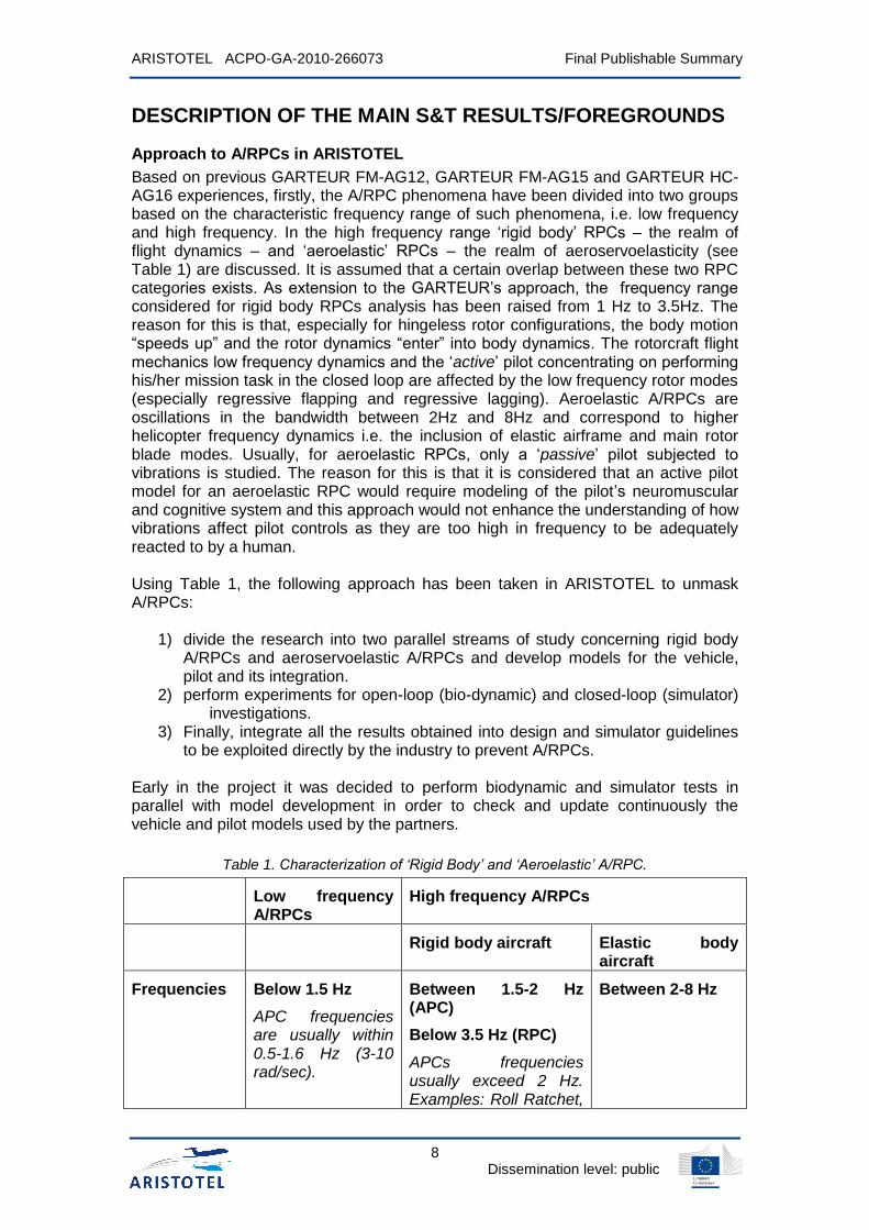
Based on previous GARTEUR FM-AG12, GARTEUR FM-AG15 and GARTEUR HC-AG16 experiences, firstly, the A/RPC phenomena have been divided into two groups based on the characteristic frequency range of such phenomena, i.e. low frequency and high frequency. In the high frequency range ‘rigid body’ RPCs – the realm of flight dynamics – and ‘aeroelastic’ RPCs – the realm of aeroservoelasticity (see Table 1) are discussed. It is assumed that a certain overlap between these two RPC categories exists. As extension to the GARTEUR’s approach, the frequency range considered for rigid body RPCs analysis has been raised from 1 Hz to 3.5Hz. The reason for this is that, especially for hingeless rotor configurations, the body motion “speeds up” and the rotor dynamics “enter” into body dynamics. The rotorcraft flight mechanics low frequency dynamics and the ‘active’ pilot concentrating on performing his/her mission task in the closed loop are affected by the low frequency rotor modes (especially regressive flapping and regressive lagging). Aeroelastic A/RPCs are oscillations in the bandwidth between 2Hz and 8Hz and correspond to higher helicopter frequency dynamics i.e. the inclusion of elastic airframe and main rotor blade modes. Usually, for aeroelastic RPCs, only a ‘passive’ pilot subjected to vibrations is studied. The reason for this is that it is considered that an active pilot model for an aeroelastic RPC would require modeling of the pilot’s neuromuscular and cognitive system and this approach would not enhance the understanding of how vibrations affect pilot controls as they are too high in frequency to be adequately reacted to by a human. Using Table 1, the following approach has been taken in ARISTOTEL to unmask A/RPCs:
1) divide the research into two parallel streams of study concerning rigid body A/RPCs and aeroservoelastic A/RPCs and develop models for the vehicle, pilot and its integration.
2) perform experiments for open-loop (bio-dynamic) and closed-loop (simulator) investigations.
3) Finally, integrate all the results obtained into design and simulator guidelines to be exploited directly by the industry to prevent A/RPCs.
Early in the project it was decided to perform biodynamic and simulator tests in parallel with model development in order to check and update continuously the vehicle and pilot models used by the partners.
Table 1. Characterization of ‘Rigid Body’ and ‘Aeroelastic’ A/RPC.
Low frequency A/RPCs
High frequency A/RPCs
Rigid body aircraft Elastic body aircraft
Frequencies Below 1.5 Hz
APC frequencies are usually within 0.5-1.6 Hz (3-10 rad/sec).
Between 1.5-2 Hz (APC)
Below 3.5 Hz (RPC)
APCs frequencies usually exceed 2 Hz. Examples: Roll Ratchet,
Between 2-8 Hz

ARISTOTEL ACPO-GA-2010-266073 Final Publishable Summary
9 Dissemination level: public
bob-weight.
Causes 1) Inadequate vehicle dynamic characteristics (aircraft + control system):
High order of the system, large phase delay, low damping, and others.
Control system delay.
Actuator or control surface rate limit.
2) High control sensitivity (command gain), low force-displacement gradient.
1) Biodynamic interaction: The biodynamic interaction in the “pilot + manipulator + aircraft” system arises due to high-frequency aircraft response to pilot activity caused by inadequate aircraft characteristics (high natural frequencies, low roll mode time constant, high control sensitivity, large pilot location relative to the centre of gravity)
1) Biodynamic interaction: The biodynamic interaction in the pilot-aircraft system arises due to aircraft structural elasticity and leads to involuntary manipulator deflections transferred to control system.
Characteristics Pilot closes the loop according to the information received through visual or acceleration perception channels.
The pilot closes the control loop due to aircraft accelerations acting on the body and the arm cause involuntary manipulator deflections which go to the control system and lead to high-frequency A/RPC.
The pilot closes the control loop due to structural oscillations and inertial forces acting on the body and the arm cause involuntary manipulator deflections which go to the control system and provoke high-frequency A/RPC.
Critical components
Flight control system Airframe modes
Pilot modeling ‘Active’ pilot concentrating on a task
‘Active’ pilot concentrating on a task
‘Passive’ pilot subjected to vibrations
Vehicle dynamics modeling
Flight mechanics Flight mechanics Structural dynamics
The following facilities were used in ARISTOTEL (see Figure 2):
SIMONA (Simulation Motion and Navigation Technologies) Research Simulator is a motion-based generic 6-degree–of-freedom research simulator available at Delft University of Technology, The Netherlands. Hydraulic power is used to drive the motion system. The motion platform gives the following performance: Pitch +24.3/-23.7°; Roll +/-25.9°; Yaw +/-41.6° Heave+0.678/-0.636 m; Surge +1.259/-0.981 m; Sway +/-1.031 m. In-house motion cuing algorithms are present to tune the motion characteristics

ARISTOTEL ACPO-GA-2010-266073 Final Publishable Summary
10 Dissemination level: public
according to simulated aircraft dynamics. The visual field of SIMONA is for the moment limited to that of a fixed wing aircraft.
HELIFLIGHT-R is one of the generic motion-based 6 degree-of-freedom research simulator available at the Bibby flight simulation facility at the University of Liverpool. The motion platform utilises six electric actuators in a hexapod architecture. The motion platform gives the following performance: Pitch +34.0/-32.0°; Roll +/-28.0°; Yaw +/-44.0° Heave+/-0.5 m; Surge +/-0.93 m; Sway +/-0.86 m. The facility features a blended 210° x 70° field-of-view.
FS-102 simulator is the simulator available at TsAGI. It has a 6 DOF motion system of synergistic type that consists of 6 actuators with hydrostatic bearings. The motion platform gives the following performance: Pitch +/-37.8°; Roll +/-35°; Yaw +/-60° Heave+/-1.23 m; Surge +/-1.75 m; Sway +/-1.475 m.
GRACE (Generic Research Aircraft Cockpit Environment GRACE) is the motion-based 6-degree-of-motion simulator operated at NLR. It is a modular reconfigurable transport aircraft simulator for civil flight operations research and prototyping. The simulator has an electrical motion platform. The basic layout of the simulator is based on Airbus (A330/340) cockpits, but configurations as Boeing (B747), business jet and Fokker can be interchanged.
GRACE (NLR)
FS-102 (TsAGI)
HELIFLIGHT-R (UoL)
SIMONA (TUD)
Figure 2. Simulators used in ARISTOTEL.
Defining A/RPCs
The first dilemma that needs to be solved when analyzing aircraft oscillatory behavior is whether or not a particular event is an A/RPC. According to (Mitchel and Klyde, 2006), ten different definitions seem to exist in the open literature and the aerospace community is often unable to agree upon whether or not a particular event is an A/RPC. Also, it has been argued by some experts that renaming the PIO/PAOs and call them APCs in the case of aircraft or RPCs in the case of rotorcraft is even more confusing. “The introduction of the term “Aircraft-Pilot Coupling” (APC, or sometimes A-PC) in the mid-1990’s contributed to the obscuration of the obvious: while the intent of this new term was to capture both oscillatory and non-oscillatory adverse behaviors of the aircraft-pilot system, it has further factionalized the debate as there

ARISTOTEL ACPO-GA-2010-266073 Final Publishable Summary
11 Dissemination level: public
are now questions like, “Was this event a PIO or just APC?” and “What’s the difference between PIO and APC?” to be addressed in the ongoing debates.” (Mitchel and Klyde, 2006). Presently, PIO/PAO are considered subclasses of A/RPCs. The following definition was then proposed to be used throughout the project:
This definition is the result of an exhaustive discussion between the project partners where every single word has been given the right weight in order not to judge too severely or too negligently the risk of actual A/RPC happening. Three keywords can be highlighted from this definition, which can be found in almost every RPC accident:
Oscillatory behaviour: every RPC event is related to oscillatory behavior perceived (and then induced) by the pilot. If not leading to crash and catastrophic consequences, these events are related to extreme discomfort and are reported as dangerous happenings.
Mental Mismatch: is always related to RPC in that the pilot shows a wrong mental model of the dynamics of the system he/she is leading/lagging and increasing levels of unawareness of the command input he/she is giving. It is obvious that both descriptions of PIO and PAO as given above can be related to mental mismatch, leading to either a wrong command input in the PIO or to a totally unaware command input in the case of PAO.
Out-of-phase behavior: every fully developed A/RPC reports an out-of-phase input-output response witnessing the vehicle loss of control.
Past, Present and Future A/RPCs
Past
Adverse A/RPC problems have manifested themselves since the early days of manned flight. The earliest recorded examples of PIOs date back to the Wright Brothers first aircraft (McRuer et. al, 1997). According to (AGARD, 1995), the earliest video record dates from just before World War II, with the XB-19 aircraft which suffered a pitch PIO on touchdown. Despite decades of work to develop methods for their prevention, unfavorable A/RPCs continue to occur. In order to better understand the incidence and the nature of A/RPCs, inside the ARISTOTEL project a database of A/RPCs cases was collected and updated from open literature, along with accidents investigation reports of the National Transportation Safety Board (NTSB) and Air Accidents Investigation Branch (AAIB). It was seen that most RPC events involve larger rotorcraft with conventional (non-digital) flight controls. Furthermore, many earlier recordings of RPCs were mostly associated with external underslung loads. This is true, as it is now well known that unfortunate combinations of helicopter and external load dynamics can introduce new lightly damped modes which are easily excitable by the pilot. If the pilot enters the loop, these oscillations amplify and a classical divergent RPC develops. The typical solution was to drop the load, which eliminated the problem. For normal (internal load) operations, earlier recordings of RPCs were not really mentioned in the literature. Indeed, RPCs have not typically
”'An Aircraft- or Rotorcraft-Pilot Coupling (A/RPC) is an unintentional (inadvertent) sustained or uncontrollable vehicle oscillations characterized by a mismatch between the pilot’s mental model of the vehicle dynamics and the actual vehicle dynamics. The result is that the pilot's control input is out-of-phase with the response of the vehicle, possibly causing a diverging motion.”

ARISTOTEL ACPO-GA-2010-266073 Final Publishable Summary
12 Dissemination level: public
been an issue for earlier helicopters and not many were reported during operation. Three reasons may explain this.
The first main reason is that, until recently, there were no Fly-By-Wire (FBW) operational helicopters Today, the NH-90, V-22 and BA609 are already operational with full-authority Fly-By-Wire systems and in the future commercial rotorcraft will be equipped with this system. However, many of the early FBW research helicopters developed in the mid-1980s had high equivalent time delays (more than 200 ms, usually as a summation of 50-70 ms inherent rotor response delay due to its gyroscopic inertia, some 30 ms actuator delay and additional delays due to digital computing, sensor signal shaping and filtering) and were prone to RPCs. Indeed, for example in 1982, during the flight tests undertaken with the ADOCS system (Advanced Digital/Optical Control System), rather severe PIOs were noted in high gain tasks such as slope landings.
The second reason for the absence of RPCs in earlier helicopters is that the typical APCs problems from fixed wing aircraft (e .g. fuselage bending, long control cables with bobweights, etc.) were never an issue in helicopters.
The third reason probably has to do with the differences in the piloting techniques of helicopter and fixed wing (fighter) pilots. “Highly unstable helicopters are the rule, rather than the exception and helicopter pilots are used to flying these unstable vehicles (the Bo 105 in hover, for instance, has an unstable Phugoid with a time to double amplitude of just over 2 seconds). Helicopter pilots are generally aware of the dangers of `getting into the loop' and tend to fly less aggressive than fixed wing (fighter) pilots. With the increase of controller sophistication in helicopters and the increase in simulator training, the helicopter pilots of the future may lose that gentle touch on the controls. When they do, PIOs may be just as frequent in helicopters as in fixed wing aircraft.” (Ockier, 1996)
Present
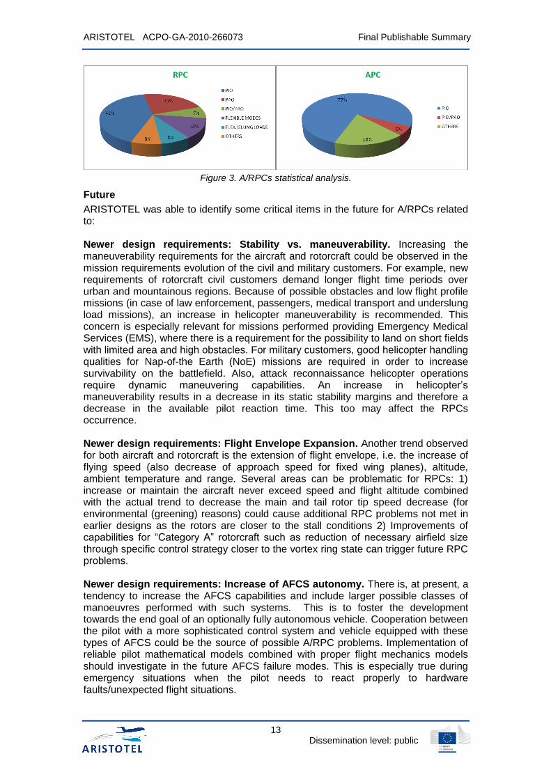
Today, particularly in modern helicopters, RPCs have become evident and can often be associated with couplings between the pilot and the lower flexible vehicle modes. Such was the case of the V-22 tiltrotor full-scale demonstrator in 2003-2004 where a divergent PAO happened, caused by a pilot who coupled with the 2.3Hz asymmetric drive train torsion mode, primarily through the lateral stick to lateral cyclic gearing control path in the lateral axis. Figure 3 shows the A/RPCs cases as a function of the PIO/PAO cases. Based on this figure it can be seen that there is still a major difference between APCs and RPCs: 77% of APCs are related to PIO events, not involving elasticity whereas the RPC situation is much more entangled. At least 50% of reports, in fact, involve aero-servo-elastic phenomena (sections named PAO, PAO/PIO, flexible modes, slung-loads). Moreover, a deeper analysis of the reported cases, shows that also during a PIO, flexibility is inherently present, due to the interactions between the rotor’s rotating frame and the fuselage’s fixed frame, and thus it is very hard to give a precise classification, as rigid and elastic phenomena are connected. ARISTOTEL has been aware of this frequency overlap range when studying A/RPCs, and developed a rigid body-aeroelastic mix of vehicle and pilot models for A/RPC detection. It is thought that a parallel rigid body/aeroelastic approach may enhance the understanding of RPC phenomena in the critical range of 1-3.5 Hz, where many accidents have been observed.
ARISTOTEL ACPO-GA-2010-266073 Final Publishable Summary
13 Dissemination level: public
Figure 3. A/RPCs statistical analysis.
Future
ARISTOTEL was able to identify some critical items in the future for A/RPCs related to: Newer design requirements: Stability vs. maneuverability. Increasing the maneuverability requirements for the aircraft and rotorcraft could be observed in the mission requirements evolution of the civil and military customers. For example, new requirements of rotorcraft civil customers demand longer flight time periods over urban and mountainous regions. Because of possible obstacles and low flight profile missions (in case of law enforcement, passengers, medical transport and underslung load missions), an increase in helicopter maneuverability is recommended. This concern is especially relevant for missions performed providing Emergency Medical Services (EMS), where there is a requirement for the possibility to land on short fields with limited area and high obstacles. For military customers, good helicopter handling qualities for Nap-of-the Earth (NoE) missions are required in order to increase survivability on the battlefield. Also, attack reconnaissance helicopter operations require dynamic maneuvering capabilities. An increase in helicopter’s maneuverability results in a decrease in its static stability margins and therefore a decrease in the available pilot reaction time. This too may affect the RPCs occurrence. Newer design requirements: Flight Envelope Expansion. Another trend observed for both aircraft and rotorcraft is the extension of flight envelope, i.e. the increase of flying speed (also decrease of approach speed for fixed wing planes), altitude, ambient temperature and range. Several areas can be problematic for RPCs: 1) increase or maintain the aircraft never exceed speed and flight altitude combined with the actual trend to decrease the main and tail rotor tip speed decrease (for environmental (greening) reasons) could cause additional RPC problems not met in earlier designs as the rotors are closer to the stall conditions 2) Improvements of capabilities for “Category A” rotorcraft such as reduction of necessary airfield size through specific control strategy closer to the vortex ring state can trigger future RPC problems. Newer design requirements: Increase of AFCS autonomy. There is, at present, a tendency to increase the AFCS capabilities and include larger possible classes of manoeuvres performed with such systems. This is to foster the development towards the end goal of an optionally fully autonomous vehicle. Cooperation between the pilot with a more sophisticated control system and vehicle equipped with these types of AFCS could be the source of possible A/RPC problems. Implementation of reliable pilot mathematical models combined with proper flight mechanics models should investigate in the future AFCS failure modes. This is especially true during emergency situations when the pilot needs to react properly to hardware faults/unexpected flight situations.

ARISTOTEL ACPO-GA-2010-266073 Final Publishable Summary
14 Dissemination level: public
Newer design requirements: Decrease of noise and vibration levels. New rotorcraft, designed to meet 'green' requirements, could lead to more RPC problems. The future design of new aerial vehicles - such as heavy rotorcraft or large transport aircraft entails to the development of more flexible conventional structures, or new structural design paradigms. The overall FCS must include the more pronounced flexibility effect in its design. The reason for this is that the natural frequencies of the fuselage and wing/rotor blade structural modes decrease as their size increases. As a consequence, the lower frequency structural modes have a greater influence on the vehicle dynamic response. Additionally, weight reduction through the use of composite materials contributes to the development of more flexible structures. The structural flexibility also affects the vehicle aeroelastic stability where the pilot biodynamic feedback and FCS feedback can interact with the vehicle structure, leading to pilot/control system assisted excitation of the structural modes. Evolution of possible technical solutions: Advanced main and tail rotor schemes. Designs for more controllable helicopters have resulted in stiffer main rotor hub structures. The rotor design evolution from fully articulated to hingeless and bearingless design results in an increase of the number of rotor modes affected by the pilot response. the implementation of new rotor control techniques such as Higher Harmonic Control (HHC) or Individual Blade Control (IBC) increases also the necessity for RPC analysis. Solutions, such as swashplateless rotors, may introduce new types of instabilities which can trigger RPCs. Tailrotor replacement by Fenestron, NOTAR or other solutions may also cause problems, and require an RPC sensitivity analysis to discover specific critical operating conditions. Evolution of possible technical solutions: Increasing the role of electronics in cockpit design. Commercial aircraft manufacturers are veering towards FBW control technologies. It is well known that high automation in the cabin reduces situational awareness. While FBW can significantly enhance the aircraft manoeuvrability, it also increases controller bandwidth. This may result in adverse interactions between the human pilot, the flight control system and the aircraft dynamics. These interactions become more critical in the case of structural spill-over instabilities, due to poor control laws designs or incompatible airframe FCS updates. This highlights the need for robust control design techniques and effective analysis methods. The design of more autonomous AFCS with larger authority margin may lead to future RPCs. Design analysis should answer several questions such as: 1) Is the pilot capable of maintaining control with partial/full AFCS out of order? 2) What is the pilot time delay for overruling the AFCS when needed and what are the appropriate parameters to be used for tuning the AFCS for safe operation? 3) What are the most critical flight states when malfunctions of AFCS occur? Answering these questions requires appropriate pilot mathematical models and extensive simulations with real human pilot participation. Evolution of possible technical solutions: Smart structures and smart materials. Incorporation into design new types of adaptable structures used on helicopter as well as additional controls could add new degrees of freedom into RPC analyses. Evolution of certification requirements: Manoeuvrability requirements. There is a tendency to introduce new requirements in certification documents for performing specific maneuvers. MIL-H-8501A and later MIL-F-83300 standards, which were applicable in the past, defined limits for helicopter responses based on pilot control input. ADS-33E and, more recently, Handling Qualities of Rotorcraft with External Slung Loads, defined handling qualities per specific maneuvers. Presently, very little requirements are given with respect to RPCs.

ARISTOTEL ACPO-GA-2010-266073 Final Publishable Summary
15 Dissemination level: public
Evolution of certification requirements: Civil design requirements evolution. The evolution of civil helicopter design regulations - FAR 27/29, JAR 27/29, CS 27/29 for helicopters and FAR 23/25, JAR 27/29, CS 27/29 - shows that the stability requirements have been strengthened in time (such as damping requirements, pilot response delay time with AFCS). Fulfilling both the stability specs for civilian market and manoeuvrability specs for military requires the use of trade-offs. Future RPC analyses could help to find optimal control strategy for the physical pilot capabilities. Evolution of certification requirements: Environmental requirements. The 'green' environmental aspects, such as restrictive noise, vibration, pollution requirements, new structures, materials, systems, control strategies etc., which are presently not included in the design but might become compulsory in the future, could affect the RPC level. The ACARE agenda of the European Community together with the JTI “Clean Sky” initiatives (http://www.cleansky.eu/) for implementation of new technology, smart structures, new materials, new control strategies for take-off and approach flight paths in both fixed wing and rotorcraft (increased maneuverability, higher climb and descend ratios near airfields and helipads) may affect the tendencies for RPCs.
Rigid body RPC Findings
Rigid body analysis involved only RPC cases. Within the ARISTOTEL project, two Rigid Body Test Campaigns (RBTC) were conducted in Delft in the SIMONA simulator (SRS) and the Liverpool simulator (HFR). The 1st RBTC was primarily used to continue investigations initiated in GARTEUR AG-16. In this campaign, predictions were made using candidate criteria, and piloted assessment was used to determine the efficacy of these predictions. The 1st RBTC was also used to assess improvements with regards to the trial process, that could be implemented for the planned 2nd RBTC. Furthermore, results from the 1st RBTC were used to define the research questions for the 2nd RBTC. The 2nd RBTC focussed on the development of tasks and manoeuvres to expose RPC tendencies. The sensitivity of the vehicle model to RPC incipience was observed through changes in task performance. For both test campaigns, a number of current or former military test pilots were used. Four pilots participated in the 1st RBTC (Pilots A-D). In the 2nd RBTC, a total of 5 pilots participated, three of whom completed tests in both SRS and HFR (A,C, D). Pilots E and F completed tests in only in HFR or SRS, respectively. Pilot B did not participate in the 2nd RBTC. During both campaigns, RPC incipience was judged through pilot subjective assessment. In both test campaigns, vehicle handling qualities and task difficulty were measured using the Cooper-Harper Handling Qualities Rating (HQR) Scale. Furthermore, in the 1st RBTC, pilot workload was measured using the Bedford Workload Rating Scale. In the 1st RBTC, RPC tendencies were assessed using the Pilot Induced Oscillations Susceptibility scale. In the 2nd campaign, a novel PIO scale was introduced. The following lessons were learned from the Rigid Body Test Campaign: 1) Suitability of Tasks to Expose RPCs The primary objective of the 1st RBTC was to assess the suitability of ADS-33 type tasks to expose RPC tendencies in the vehicle model. The candidate manoeuvres selected and their positive and negative results are shown in Table 2. Figure 4 presents the precision hover tested in the project.

ARISTOTEL ACPO-GA-2010-266073 Final Publishable Summary
16 Dissemination level: public
Table 2. Task suitability during simulator tests

ARISTOTEL ACPO-GA-2010-266073 Final Publishable Summary
17 Dissemination level: public
Figure 4 Examples of Precision Hover course layout used during investigation
2) Subjectivity of the Pilot-Induced Oscillations Ratings Scale In the 1st RBTC, the primary assessment of RPC potential was made through the use of pilot’s subjective opinion. This is the traditional method for assessing RPC tendencies. The assessment was conducted using the Cooper-Harper Handling Qualities Ratings Scale, and the traditional combined Pilot-Induced Oscillations Ratings Scale (PIOR). During the campaign, many problems were experienced with the use of this last scale. The investigations undertaken as part of ARISTOTEL showed the following main problems: The first major drawback found was the influence of the lack of the available subjectivity in the scale had on the test. Unlike the HQR scale, the PIOR scale decision tree offers the pilot very little subjectivity. Pilots are trained to apply subjectivity, but are almost forced not too. If the pilot follows the decision tree based on a simple appraisal of what happened during the test, they are forced towards a numerical and descriptive rating. On many occasions, the description was found to be inconsistent with the experience during the evaluation run. With each strand of the decision tree leading to a different rating, changing to a different rating invalidates the decision tree, rendering the results obtained inconsistent. The second, related problem is the apparent mismatch between the decision tree and the descriptive terms.. Pilots often felt that the tree took them to the ‘wrong’ description; a common occurrence was arriving at PIOR 4, whilst wishing to use the description of PIOR 3. A major issue is that, when applying the scale, the end result is often the assessment of a single number. The meaning of that number is very dependent on whether the descriptive terms have been used. Often PIOR >=4 is used to denote observed PIOs. However, there is nothing in the scale to say that ‘undesirable motions’ cannot be classed as PIOs. What if the pilot does not need to reduce gain or abandon task to recover? What if he must only change strategy to counteract PIO? Finally, the scale gives little justification for the meaning of the numbers. Furthermore, the significance placed upon convergent/divergent oscillations, one of the most challenging elements to assess, makes the analysis of results very challenging. If the pilot feels that convergent oscillations have occurred after entering tight control, no matter the severity, they must award PIOR 4. It is possible that these oscillations have caused a loss of control. This makes it very important to complement PIORs with HQRs. Finally, the need for clearer descriptions and definitions within the scale became clear during the investigations. Pilots had conflicting views on what constituted oscillations and motions. Overall, it was determined that a new assessment method was required for the second test campaign.

ARISTOTEL ACPO-GA-2010-266073 Final Publishable Summary
18 Dissemination level: public
3) Simulation fidelity and its impact The simulators used in this investigation have different hardware and software capabilities, which impact the relative overall simulation fidelity. For RPC investigations, there are no standards which require objective assessment of simulation device fidelity. However, the set-up of the device is known to significantly affect results obtained from any investigation. A complete sensitivity study with regard to the effects of the cueing environment was beyond the scope of the 1st RBTC. However, an attempt to quantify the overall fidelity difference between the simulators was made, using subjective measures, namely the Usable Cueing Environment and the Motion Cueing Ratings Scale. Due to the larger Field of View, HFR consistently exhibited better Visual Cueing Ratings (VCRs) than SRS. The result was that the pilots found tasks easier to complete in HFR, finding it less challenging to maintain task performance requirements (which are obtained from the UCE). Translational cues were a major factor in the SRS UCE ratings, their absence contributing to significant pilot workload to allow task completion. Ultimately, this had an impact on the pilot’s spare capacity to assess the RPC tendencies, increasing ratings scatter and decreasing pilot confidence. The two tasks that suffered the least from the lack of visual cueing were the Precision Hover (PH) and the Roll Step (RS) manoeuvres. Both received Level 1 UCE ratings for both simulators, and pilots were able to adequately assess a) whether they met task performance requirements and b) whether RPCs had an impact on their ability to perform the task. It is suggested that when conducting RPC studies, UCEs are collected and should be verified so that the cueing is sufficient for task completion. This should allow the pilot to adequately assess RPC incipience, and significantly reduce the ratings scatter.
Pilot Modelling for rigid body A/RPC - Boundary Avoidance Tracking (BAT) Pilot model
The novel pilot modelling tools developed by ARISTOTEL for investigating A/RPC events relate to the so-called Boundary Avoidance Tracking concept (BAT) developed by Gray (Gray, 2005) for fixed wing aircraft and applied largely throughout the project by University of Liverpool (UoL) and ONERA. Gray’s main hypothesis is that during an A/RPC event, the pilot behaviour is different from the assumed point tracking (PT) flight behaviour and is more like tracking and avoiding a succession of opposing events which can be described as boundaries. GARTEUR HC-AG 16 performed simulator tests on BAT for a helicopter oscillatory pitch tracking task and in ARISTOTEL, UoL extended further the BAT research. Gray developed the BAT model, shown in Figure 5, and provided analysis techniques for estimating the associated boundary-avoidance model parameters.
Point Tracking Pilot
ModeAircraft
(Yc)
Point Tracking
Target
Error
Output
Boundary Avoidance
Pilot Mode
Boundary Time-to-
boundarySwitch
Pilot
Input
Figure 5 Gray’s boundary-avoidance tracking model
The feedback loop includes both Point Tracking (PT) and Boundary Avoidance (BA) options with a logic switch/selector that assumes no transient; only one of the

ARISTOTEL ACPO-GA-2010-266073 Final Publishable Summary
19 Dissemination level: public
tracking channels is assumed to be operating at any one time. There are 2 boundaries in this particular model, designated upper and lower and only one can be
tracked at a time. A key parameter in the BAT model is the time to boundary (b) in Figure 5, based on the distance to boundary (xb) at the current rate of approach (
bx ),
defined as b
b
b
x
x . This parameter models the pilot’s perception of the time-to-
contact, introduced by Lee as a development of Gibson’s optical flow theory of visual perception. However, it is clear that Gray independently discovered that the time to boundary was a key parameter in the pilot control strategy, without being explicitly aware of τ theory. The BA pilot model in Figure 5 is modelled as a BA feedback gain
(K), dependent on the variable b and the relationship is illustrated in Figure 6, in
which the variable is shown in the conventional (negative) sense.
maxmin
BA
τb
K
Km
Figure 6 Feedback gain variation with the time to boundary (τb)
The BAT strategy is initiated when b is lower (negatively) than the value min. If the boundary continues to be approached, the feedback gain increases linearly to its
maximum, Km, in the form min
max min
bmK K
. Using this equation, Gray hypothesized
that the control increases linearly as the boundary is approached. While the variation of this feedback gain is linear, the essence of this operation is nonlinear. This brings with it a difficulty in analysing the stability of the closed-loop systems in Figure 5. To address this issue, the BA process is modelled as the following form,
min( ) ( 1) ( )bK s s K X s in which Kb represents the BA control gain. Therefore, the BA
feedback part of Gray’s pilot model with the nonlinear τ variable can be approximately simplified into a lead perception term. The resultant closed-loop pilot model, including the vestibular and proprioceptive cues is illustrated in Figure 7.
PT Pilot Model AircraftTracking
SignalsSystem
Outputs
Neuromuscular
Actuation
Disturbance
+
Proprioceptive
Cue
+
K(s)Enabled when
τ > τmin
Vestibular Cues
+
Figure 7 Closed-loop BAT pilot model with the modelled BA pilot part for tracking task
This rudimentary level of BA description from the derivation process, combined with Figure 7, shows the essential features in the study of BAT PIOs. First, the effect of the impending boundary is modelled as an additional positive inner feedback to the

ARISTOTEL ACPO-GA-2010-266073 Final Publishable Summary
20 Dissemination level: public
closed-loop system. This formula, in essence, describes the BA process as a disturbing influence created by the impending boundary, activated at the moment that τ > τmin, on the primary (outer loop) pursuit task to which the pilot is, until that moment, giving full attention. The positive property of this feedback lies in that, with positive Kb, the resulting control effects will become larger as the detected boundary is approached (larger X(s)). Therefore, the stability of the closed-loop system pilot-vehicle dynamics can be changed and the BA process can therefore serve as a PIO trigger. The BAT-PIO onset detection can be estimated by analysing the effects of the inner linear BA perception-action form on the stability of the outer feedback loop system. Second, the structure in Figure 7 allows the investigation of the continuous contribution of the PT part of the pilot model, even after the BA process is triggered. This is different from previous work, which assumes that the PT and BA work independently, which does not reflect real pilot control activity in Figure 5. Overall then, the new structure appears to be an appropriate means to describe the pilot dynamics during the BAT process.
Prediction of rigid body RPC
A whole multitude of predictions criteria were tested in ARISTOTEL for RPC. This summary will give just an example of one of the most important criteria used for RPC prediction, i.e. the bandwidth phase delay criterion. Figure 8 shows an example of the application of the criterion to a Bo-105 helicopter during a pitch and roll tracking task flown from hover and 60kts initial flight condition when a time delay was introduced in the pilot input (increasing from 0msec to 300msec). In this figure, the ADS-33 [Fehler! Verweisquelle konnte nicht gefunden werden.] Level 1, 2 and 3 handling qualities (L1, L2, L3) were plotted together with the PIO boundaries as defined for fixed wing aircraft for pitch axis responses. Looking at the figure, it can be observed that by increasing the time delay, the predicted handling qualities of the vehicle degrade, the bandwidth decreases and the phase delay increases making the helicopter RPC prone. According to ADS-33, only roll tracking task flown at 60kts with a time delay of 300ms is PIO prone. One can also see that the theoretical bandwidth/phase delay criterion results do not show strong dependency on flight speed. Furthermore, a relatively good agreement of the results from partners’ models was found.
0 1 2 3 4 50
0.1
0.2
0.3
0.4
BW
[rad/s]
p
[s]
non PIO prone
possible PIO prone
PIO prone
L1L2L3
ADS-33E forward flight HQR for pitch tracking 60 kts.
0 ms
100 ms
200 ms
300 ms
0 1 2 3 4 50
0.1
0.2
0.3
0.4
BW
[rad/s]
p
[s]
non PIO prone
possible PIO prone
PIO prone
L1L2L3
ADS-33E forward flight HQR for pitch tracking 1 kts.
0 ms
100 ms
200 ms
300 ms

ARISTOTEL ACPO-GA-2010-266073 Final Publishable Summary
21 Dissemination level: public
0 1 2 3 4 5 6 70
0.1
0.2
0.3
0.4
BW
[rad/s]
p
[s]
L1L2L3
ADS-33E forward flight HQR for roll tracking 1 kts.
0 ms
100 ms
200 ms
300 ms
0 1 2 3 4 5 6 70
0.1
0.2
0.3
0.4
BW
[rad/s]
p
[s]
L1L2L3
ADS-33E forward flight HQR for roll tracking 60 kts.
0 ms
100 ms
200 ms
300 ms
Figure 8 Bandwidth/Phase Delay criterion applied to the Bo-105 helicopter in a pitch and roll tracking task flown from hover and 60 kts with various time delays introduced in the pilot stick
The effectiveness of the PIO criterion in predicting PIO can be evaluated according to the following performance metrics:
- Global success rate I1=(B+D)/(A+B+C+D), i.e., the percentage of cases which are correctly predicted to be PIO free or prone.
- Index of conservatism I2 = D/(C+D), i.e., the percentage of cases predicted PIO prone which have actually undergone PIO in reality with respect to the total number of predicted PIO prone cases.
- Safety index I3 = D/(A+D), i.e., the percentage of cases which are predicted by the criterion to be PIO prone, with respect to the total number of simulator test PIO cases.
As prediction was made for each axis separately (pitch or roll), those manoeuvres were chosen that solicit mainly one axis to validate the criterion: Roll axis: roll tracking task and side step manoeuvre; Pitch axis: acceleration-deceleration manoeuvre. Table 3 presents the verification of the BDP prediction.
Table 3. Assessment of BPD prediction
Tasks I1 I2 I3
Roll tracking 70% 16% 25%
Roll step 80% 60% 66%
Acceleration-deceleration
82% 33% 100%
In the roll axis, while there is a good pilot rating trend with time delays less than 200ms, the scatter of the PIOR for time delays between 200ms and 300ms does not allow a definite validation of the boundary. For example, in the roll tracking task, 5 out of 6 runs of the 300ms time delay-configuration obtained better PIOR than 2 out of 4 runs of the 200ms time delay-configuration. One reason for this result, which is presumably inconsistent according to the predictions, is that the pilot gain was not high enough. The correlation is better for the roll step manoeuvre than for the roll tracking task. In the pitch axis, a 0% success rate index is obtained for the 200ms time delay-configuration. By shifting the phase delay boundary from the actual value of 0.19 sec to 0.22 sec, the success rate will become 100%. However as the number

ARISTOTEL ACPO-GA-2010-266073 Final Publishable Summary
22 Dissemination level: public
of runs was very small for this configuration (as well as for the 100ms and 300ms time delay-configurations), correlations will have to be made with more experimental data.
Aeroelastic A/RPC Findings
Comprehensive helicopter simulation models obtained by coupling flexible fuselage dynamics, main rotor aeroelasticity, control chain dynamics and pilot behavioural dynamics were applied for RPC analysis of the IAR330 Puma and Bolkow Bo-105 helicopters. Results have shown that the passive coupling of the pilot biomechanics with the IAR330 Puma helicopter resulted in lower damped eigenvalues. Numerous couplings between the rotor and the body can occur in rotorcraft such as: the low-damped main rotor regressive lead-lag mode can be easily excited by cyclic stick inputs; the low frequency pendulum mode of external slung loads can be excited by delayed collective and/or cyclic control inputs. Other types of rotorcraft-centred deficiencies which might contribute to RPC belong to unfavourable conventional rotorcraft dynamics, such as lightly damped phugoid modes, or unfavourable roll attitude/Dutch roll mode poles. As an example of aeroelastic RPC analysis the project concentrated onto the collective bouncing (vertical bouncing) phenomenon. This is the result of a closed loop instability consisting of the coupling between main rotor collective pitching and coning, airframe (rigid and elastic) vertical motion and the collective lever motion. The instability is driven by the pilot involuntary inputs given due to vertical oscillation of his seat (the so-called pilot biodynamic feedthrough (BDFT)). To understand which particular helicopter vibrations induce adverse biodynamic couplings (BDC) effects and what mission tasks are more prone to such effects, biodynamic test trials were performed in the project for both helicopters and fixed wing aircraft. Figure 9 presents the experimental setup for the pilot’s left arm biomechanical characterisation.
Figure 9 Dr. Giuseppe Quaranta conducting the experimental setup for pilot’s left arm
biomechanical characterization: 10% (a), 50% (b), and 90% (c) reference position of the collective control inceptor
For helicopters, the results revealed some important conclusions, for example: BDFT depends on the control tasks: for the different control tasks (i.e., different neuromuscular settings), a different level of BDFT was measured; BDC depends also on the control (disturbance) axis: the highest level of BDFT is measured in sway direction, followed by the surge direction. The least amount of BDFT is measured in the heave direction. This demonstrates that the biodynamic couplings (coming only from neuromuscular adaptation in this experiment) depend not only on more obvious features such as pilot weight and posture (which can vary from pilot to pilot) but also on more elusive factors such as pilot workload and task.

ARISTOTEL ACPO-GA-2010-266073 Final Publishable Summary
23 Dissemination level: public
TsAGI formulated an approach to assess the effect of structural elasticity on aircraft handling qualities. This approach allows splitting pilot activity into an ‘active’ component, called ‘active pilot’, and a ‘passive’ component, called ‘biodynamical pilot’. The splitting of pilot activity allows the calculation of a handling qualities pilot rating increment (worsening) due to high-frequency oscillations which was evaluated in simulator trials and compared to the pilot rating of the rigid body aircraft. Figure 10 presents the pilot controlling an elastic aircraft with the active and passive components.
Figure 10 Block-diagram of pilot control activity for elastic aircraft
Figure 11 shows the method to assess, as a new handling qualities criterion, the pilot rating worsening due to biodynamical effect of fixed-wing aircraft structural elasticity and cockpit control configuration. The assessment of aero-servo-elastic APC tendency in the roll control axis and the role of the control inceptor requires the following characteristics:
- Yny , aircraft transfer function for the lateral accelerations - Yp , aircraft transfer function for roll rate
According to the HQ criterion, pilot rating deterioration can be determined according to the empirical function shown in Figure 11 or to the following expression:
020 if 032
020 if 0
.λ,.λlg
.λ,PRΔ
(1)
Calculation of parameter is made in accordance with the following expression:
р
n
σ
σλ
y
’ (2)
where p is the root-mean-square (RMS) of roll rate, ny is the RMS of lateral accelerations in the pilot’s location caused by structural elasticity oscillations. The
values of p and ny in (2) both depend on inceptor configuration (type, characteristics) and aircraft structural characteristics.

ARISTOTEL ACPO-GA-2010-266073 Final Publishable Summary
24 Dissemination level: public
Figure 11 New handling qualities criterion: pilot rating worsening due to biodynamical effect of fixed-wing aircraft structural elasticity and cockpit control configuration.
Experiments at TsAGI and NLR demonstrated also that varying the manipulator characteristics, i.e. using either a control yoke (wheel) system like in most of the airliners, a central stick like in most military aircraft or a side-stick as in the new fly-by-wire airliners, affects also the BDFT. The greatest pilot rating worsening due to biodynamic interaction between the pilot and the elastic accelerations corresponds to the central stick and side stick systems. This demonstrates that in many modern civil aircraft (such as Airbus A320, Airbus A380 using a side stick manipulator) and military aircraft (such as Daussault Rafale, F-22 Raptor, F-35 Joint Strike Fighter with a side-stick and Eurofighter Typhoon and Mirage III with a centre-stick) BDFT effects are more important than in the past. Also, helicopters and tilt rotors (as V-22 Osprey) use mainly centre-stick manipulators and thus are BDFT sensitive.
ARISTOTEL ACPO-GA-2010-266073 Final Publishable Summary
25 Dissemination level: public
POTENTIAL IMPACT AND THE MAIN DISSEMINATION ACTIVITIES AND EXPLOITATION OF RESULTS
Project relevance to the FP7 goals
The European Community has set a joint safety initiative target to cut aviation accidents by 80 percent by 2020.The ARISTOTEL project aimed to support the European endeavour to reduce the rate of aviation accidents by tackling the area of A/RPC suppression and prevention. In this respect, the project is highly relevant to the priorities of the activity “Ensuring Customer Satisfaction and Safety” of the FP7 Cooperation Work Programme in the areas of “Aircraft safety” and “Operational safety” and activity “Improving Cost Efficiency” in the area Aircraft development cost. The project was also relevant to the ACARE “Strategic Research Agenda” report 2004 and ACARE report “European Aeronautics: A vision for 2020” contributing to three of its five High Level Target Concepts set out for the work to 2020, i.e. “Highly Customer Oriented” - contributor Safety, “Highly Time Efficient” and “Highly Cost Efficient” targets for future aeronautics. The ARISTOTEL project directly addresses the enhancement of aviation safety. Its primary impact can be summarized as follows:
ARISTOTEL contributes to the amelioration of the accident rate registered especially with rotorcraft, a rate which is presently much higher than for fixed-wing aircraft. For example, recent statistics show that the rate of accidents caused by pilot loss of control in the case of rotorcraft averages 23% (from the total number of accidents) whereas in the case of fixed-wing aircraft the rate stays at a constant level of approximately 15%. As RPCs are typically pilot loss of control events, it is expected that advancing the state-of-the-art in RPC problems will result in reducing the number of accidents caused by pilot loss of control.
ARISTOTEL provides an understanding of the causes that can lead to RPC events in present and future rotorcraft designs that use advanced flight control and fly-by-wire systems;
ARISTOTEL analyses the specific human-machine interfaces involved in A/RPC events and how dangerous these are for the safety of current and future rotorcraft designs;
ARISTOTEL provides modelling and reliable simulation for both rigid body and aero-servo-elastic RPC prediction from three perspectives: modelling the human pilot; modelling the vehicle and modelling the interactions between the human pilot and the vehicle, enabling RPC-prone designs to be detected and corrected more efficiently;
ARISTOTEL reduces or removes the A/RPC proneness of an air-vehicle through the development of new tools. For example, the Boundary Avoidance Tracking pilot model and prediction criteria and guidelines are capable of being applied throughout the design process. These new prediction tools allow the efficient reduction of annoying dangerous A/RPC in current and future aircraft and rotorcraft;
ARISTOTEL provides simulator protocols for unmasking A/RPCs in the simulator, helping to design simulation trials that will uncover adverse A/RPC and thus diminish the chance of accidents.
ARISTOTEL contributes to ensuring reliable and effective human performance operating in an A/RPC-free designed configuration.
ARISTOTEL enhances carefree handling of the aircraft/rotorcraft. Carefree handling means the ability of the pilot to fly throughout the aircraft’s

ARISTOTEL ACPO-GA-2010-266073 Final Publishable Summary
26 Dissemination level: public
operational flight envelope without concern for exceeding structural, aerodynamic or control limits.
ARISTOTEL contributes to the extension of certification standards with A/RPC criteria. Such criteria are at the moment barely considered in the certification standards. The addition of A/RPC criteria will contribute to the improvement of the certification standards.
The ARISTOTEL project brought together European industrial partners supplemented with high level research institutes from all over Europe including Russia and universities experienced in the problems to be addressed. The innovations with respect at the state-of-the-art in A/RPC prediction include:
New pilot models and methods for A/RPC prediction applicable to fixed and rotary wings (see previous chapter for more details);
New flight simulator test methods for recognising adverse A/RPC phenomena.
An analysis of the world helicopter market trends over recent years reveals that Europe is leading the rotorcraft and aircraft world, not only in terms of market share, but also with regard to technological innovation. However, high levels of public support for research and development in the USA and China will put pressure on the European dominance. To ensure that the leading position is maintained in the future continued research and innovation will be required.
The present project, through its goals of developing innovative guidelines, methods and training protocols for enhancing A/RPC prediction and prevention in European designs, would help to ensure this leading position in the future in Europe. The results of this project will speed up the development, testing and certification of present and future rotorcraft and, even more important, it will create safer designs. It should be underlined that at the moment there are no design guidelines either in Europe or the USA for investigating the aero-servo-elastic A/RPCs of highly augmented rotorcraft. The approach formulated by TsAGI to assess the effect of structural elasticity on aircraft handling qualities is an important step forward (see more details above). Also, it is not defined how the characteristics of aero-servo-elastic RPCs should be implemented in the rigid body RPC analysis which is finally used for real-time training of aircraft/rotorcraft pilots in the simulator. ARISTOTEL performed research in this area and provided the analyst with the unique capability to evaluate the sensitivity of complex aeromechanical systems to the biomechanical properties of the pilot.
Main project outputs dissemination and exploitation strategy
Pilot-vehicle models to simulate rigid-body RPC phenomena. The models developed will be used to predict RPC tendencies of the present and future rotorcraft equipped with a partial or total fly-by-wire flight control system.
Pilot-vehicle models to simulate aero-servo-elastic RPC phenomena. The models developed will be used in design and control of aero-servo-elastic RPCs of present and future rotorcraft including tiltrotors.
Pilot-vehicle models capable of simulating aero-servo-elastic APC phenomena. The developed models will be used for the design and evaluation of pilot manipulator control systems for present and future large fly-by-wire transport aircraft. Associated new APC design criteria that take the pilot control system characteristics into account will be part of the A/RPC alleviation guidelines.

ARISTOTEL ACPO-GA-2010-266073 Final Publishable Summary
27 Dissemination level: public
Criteria and guidelines for A/RPC prediction. These will be used to set requirements for A/RPC-free configurations. It is intended to propose the newly developed criteria to European Airworthiness Authorities as a baseline for A/RPC qualification and certification studies.
Criteria and guidelines for A/RPC alleviation. They will be used in Flight Control System design studies of present and future rotorcraft. The application of A/RPC criteria that take the pilot-vehicle interactions into account are expected to improve the performance and safety of the vehicle in terms of robustness against system and/or atmospheric disturbances.
Criteria and guidelines for A/RPC flight simulator testing. These will help manufacturers and research institutions of both rotorcraft and fixed wing aircraft to define simulator fidelity requirements for effective A/RPC reproduction and testing.
Criteria and guidelines for A/RPC pilot training. The above guidelines will also be used to train pilots more effectively in recognising adverse A/RPC tendencies in actual flight situations.
The results of the ARISTOTEL project can already be exploited since it is intended to use them in the design development process:
Helicopter manufacturer’s will be able to improve their in-house advanced rotorcraft codes with A/ RPC prediction;
The use of a handbook of guidelines and criteria for the prediction and alleviation of A/RPC can be used by the manufacturers of both rotorcraft and fixed wing aircraft.
Manufacturers will be able to directly apply a more structured approach to the design of highly augmented rotorcraft and aircraft and demonstration of A/RPC related phenomena.
The project consortium partners own simulators that can use the protocols developed for unmasking adverse A/RPC tendencies during training sessions of aircraft/rotorcraft pilots, increasing thus the safety of future designs. The simulator results will constitute the basis for defining future explicit flight test sessions seeking out adverse RPC tendencies without endangering the pilot’s safety.
Therefore, the project leads to safer aircraft and rotorcraft operations through improved design, more effective pilot training and proper real-time detection. The Consortium has concentrated our attention especially on RPC prediction as the rotorcraft RPC prediction significantly lags that of fixed-wing aircraft APC, building on the work already done in the fixed-wing community.