final international iso/fdis draft … draft iso/tc 43/sc 1 secretariat: ds voting begins on:...
TRANSCRIPT

Please see the administrative notes on page iii
RECIPIENTS OF THIS DRAFT ARE INVITED TOSUBMIT, WITH THEIR COMMENTS, NOTIFICATION OF ANY RELEVANT PATENT RIGHTS OF WHICHTHEY ARE AWARE AND TO PROVIDE SUPPORT-ING DOCUMENTATION.
IN ADDITION TO THEIR EVALUATION AS BEING ACCEPTABLE FOR INDUSTRIAL, TECHNO-LOGICAL, COMMERCIAL AND USER PURPOSES,DRAFT INTERNATIONAL STANDARDS MAY ONOCCASION HAVE TO BE CONSIDERED IN THELIGHT OF THEIR POTENTIAL TO BECOME STAN-DARDS TO WHICH REFERENCE MAY BE MADE INNATIONAL REGULATIONS.
Reference numberISO/FDIS 5130:2006(E)
© ISO 2006
FINAL DRAFT
ISO/TC 43/SC 1
Secretariat: DS
Voting begins on: 2006-12-21
Voting terminates on: 2007-02-21
INTERNATIONAL STANDARD
ISO/FDIS5130
Acoustics — Measurements of sound pressure level emitted by stationary road vehicles
Acoustique — Mesurages du niveau de pression acoustique émis par les véhicules routiers en stationnement

ISO/FDIS 5130:2006(E)
PDF disclaimer This PDF file may contain embedded typefaces. In accordance with Adobe's licensing policy, this file may be printed or viewed but shall not be edited unless the typefaces which are embedded are licensed to and installed on the computer performing the editing. In downloading this file, parties accept therein the responsibility of not infringing Adobe's licensing policy. The ISO Central Secretariat accepts no liability in this area.
Adobe is a trademark of Adobe Systems Incorporated.
Details of the software products used to create this PDF file can be found in the General Info relative to the file; the PDF-creation parameters were optimized for printing. Every care has been taken to ensure that the file is suitable for use by ISO member bodies. In the unlikely event that a problem relating to it is found, please inform the Central Secretariat at the address given below.
Copyright notice
This ISO document is a Draft International Standard and is copyright-protected by ISO. Except as permitted under the applicable laws of the user's country, neither this ISO draft nor any extract from it may be reproduced, stored in a retrieval system or transmitted in any form or by any means, electronic, photocopying, recording or otherwise, without prior written permission being secured.
Requests for permission to reproduce should be addressed to either ISO at the address below or ISO's member body in the country of the requester.
ISO copyright office Case postale 56 • CH-1211 Geneva 20 Tel. + 41 22 749 01 11 Fax + 41 22 749 09 47 E-mail [email protected] Web www.iso.org
Reproduction may be subject to royalty payments or a licensing agreement.
Violators may be prosecuted.
ii © ISO 2006 – All rights reserved

ISO/FDIS 5130:2006(E)
© ISO 2006 – All rights reserved iii
In accordance with the provisions of Council Resolution 15/1993, this document is circulated in the English language only.

ISO/FDIS 5130:2006(E)
iv © ISO 2006 – All rights reserved
Contents Page
Foreword ............................................................................................................................................................. v Introduction ....................................................................................................................................................... vi 1 Scope...................................................................................................................................................... 1 2 Normative references ........................................................................................................................... 1 3 Terms and definitions........................................................................................................................... 2 4 Instrumentation ..................................................................................................................................... 2 4.1 Instrumentation for acoustical measurement .................................................................................... 2 4.2 Instrumentation for engine-speed measurement .............................................................................. 3 5 Acoustical environment, meteorological conditions and background noise................................. 3 5.1 Test site.................................................................................................................................................. 3 5.2 Meteorological conditions.................................................................................................................... 3 5.3 Background noise................................................................................................................................. 3 6 Test procedure ...................................................................................................................................... 3 6.1 General comments................................................................................................................................ 3 6.2 Positioning and preparation of the vehicle ........................................................................................ 4 6.3 Microphone position............................................................................................................................. 4 6.4 Target engine speed ........................................................................................................................... 10 6.5 Engine operating conditions.............................................................................................................. 10 6.6 Multi-mode exhaust system............................................................................................................... 10 7 Measurements ..................................................................................................................................... 10 8 Interpretation of results...................................................................................................................... 11 9 Measurement uncertainty................................................................................................................... 11 10 Test report............................................................................................................................................ 12 Annex A (informative) Technical background information .......................................................................... 13 Annex B (informative) Measurement uncertainty — Framework for uncertainty analysis
based on ISO Guide 98 ....................................................................................................................... 14 Bibliography ..................................................................................................................................................... 17

ISO/FDIS 5130:2006(E)
© ISO 2006 – All rights reserved v
Foreword
ISO (the International Organization for Standardization) is a worldwide federation of national standards bodies (ISO member bodies). The work of preparing International Standards is normally carried out through ISO technical committees. Each member body interested in a subject for which a technical committee has been established has the right to be represented on that committee. International organizations, governmental and non-governmental, in liaison with ISO, also take part in the work. ISO collaborates closely with the International Electrotechnical Commission (IEC) on all matters of electrotechnical standardization.
International Standards are drafted in accordance with the rules given in the ISO/IEC Directives, Part 2.
The main task of technical committees is to prepare International Standards. Draft International Standards adopted by the technical committees are circulated to the member bodies for voting. Publication as an International Standard requires approval by at least 75 % of the member bodies casting a vote.
Attention is drawn to the possibility that some of the elements of this document may be the subject of patent rights. ISO shall not be held responsible for identifying any or all such patent rights.
ISO 5130 was prepared by Technical Committee ISO/TC 43, Acoustics, Subcommittee SC 1, Noise.
This second edition cancels and replaces the first edition (ISO 5130:1982), which has been technically revised.

ISO/FDIS 5130:2006(E)
vi © ISO 2006 – All rights reserved
Introduction
This sound pressure level measurement procedure has been developed for use in the engineering evaluation of the sound pressure level performance of road vehicles in the vicinity of the exhaust systems. The method is intended to check vehicles in use and also to determine variations in the exhaust sound pressure level that can result from
⎯ the wear, maladjustment or modification of particular components, when the defect does not appear by visual inspection;
⎯ the partial or complete removal of devices reducing the emission of certain sound pressure levels.
It is possible to determine some of these variations by comparing the measurements with reference measurements made under similar conditions, for example during the type approval of the vehicle, using the same method. Other variations can be detected only when the engine is operated at a realistic load.
The document incorporates certain provisions of SAE J1492:1998-05, for measuring the sound pressure levels of exhaust systems of passenger cars and light trucks.

FINAL DRAFT INTERNATIONAL STANDARD ISO/FDIS 5130:2006(E)
© ISO 2006 – All rights reserved 1
Acoustics — Measurements of sound pressure level emitted by stationary road vehicles
1 Scope
This International Standard specifies a test procedure, environment and instrumentation for measuring the exterior sound pressure levels from road vehicles under stationary conditions, providing a continuous measure of the sound pressure level over a range of engine speeds. This International Standard applies only to road vehicles of categories L, M and N equipped with internal combustion engines.
The method is designed to meet the requirements of simplicity as far as they are consistent with reproducibility of results under the operating conditions of the vehicle.
It is within the scope of this International Standard to measure the stationary A-weighted sound pressure level during
⎯ type approval measurements of vehicle;
⎯ measurements at the manufacturing stage;
⎯ measurements at official testing stations;
⎯ measurements at roadside testing.
This International Standard specifies neither a method to check the exhaust sound pressure level when the engine is operated at realistic loads nor a method to check the exhaust sound pressure levels against a general noise limit for categories of road vehicles.
Technical background information is given in Annex A.
2 Normative references
The following referenced documents are indispensable for the application of this document. For dated references, only the edition cited applies. For undated references, the latest edition of the referenced document (including any amendments) applies.
ISO 5725 (all parts), Accuracy (trueness and precision) of measurement methods and results
IEC 60942, Electroacoustics — Sound calibrators
IEC 61672-1, Electroacoustics — Sound level meters — Part 1: Specifications
ISO Guide 98, Guide to the expression of uncertainty in measurement (GUM)

ISO/FDIS 5130:2006(E)
2 © ISO 2006 – All rights reserved
3 Terms and definitions
For the purposes of this document, the following terms and definitions apply.
3.1 vehicle category L motor vehicles with fewer than four wheels
NOTE United Nations Economic Commission for Europe (UN ECE) document TRANS/WP.29/78/Rev.1/Amend.4 (26 April 2005) extended the L category to four-wheeled vehicles as defined by L6 and L7 in ISO 362-1:—, 3.4.1.5 and 3.4.1.6.
3.2 vehicle category M power-driven vehicles having at least four wheels and used for the carriage of passengers
3.3 vehicle category N power-driven vehicles having at least four wheels and used for the carriage of goods
3.4 rated engine speed S engine speed at which the engine develops its rated maximum net power as stated by the manufacturer
NOTE 1 If the rated maximum net power is reached at several engine speeds, the S used in this International Standard is the highest engine speed at which the rated maximum net power is reached.
NOTE 2 ISO 80000-2 defines this term as “rated engine rotational frequency”. The term “rated engine speed” was retained due to its common understanding by practitioners and use in government regulations.
4 Instrumentation
4.1 Instrumentation for acoustical measurement
4.1.1 General
The sound level meter or equivalent measuring system, including the windscreen recommended by the manufacturer, shall meet the requirements of class 1 instruments, in accordance with IEC 61672-1.
The measurements shall be made using the frequency-weighting A, and the time-weighting F.
4.1.2 Calibration
At the beginning and at the end of every measurement session, the entire measuring system shall be checked by means of a sound calibrator that fulfils the requirements for sound calibrators of class 1 in accordance with IEC 60942. Without any further adjustment, the difference between the readings of two consecutive checks shall be less than or equal to 0,5 dB. If this value is exceeded, the results of the measurements obtained after the previous satisfactory check shall be discarded.
4.1.3 Compliance with requirements
Compliance of the instrumentation system with the requirements of IEC 61672-1 and compliance of the sound calibration device with the requirements of IEC 60942 shall be verified by the existence of a valid certificate of compliance. These certificates shall be deemed to be valid if verification of compliance with the respective standards was conducted within the previous 24 months for the instrumentation system and 12 months for the sound calibration device. All compliance testing shall be conducted by a laboratory that is authorized to perform calibrations traceable to the appropriate standards.

ISO/FDIS 5130:2006(E)
© ISO 2006 – All rights reserved 3
4.2 Instrumentation for engine-speed measurement
The rotational speed of the engine shall be measured with an instrument meeting the specification limits of at least ± 2 % or better at the engine speeds required for the measurements being performed.
5 Acoustical environment, meteorological conditions and background noise
5.1 Test site
A suitable test site shall be outdoors and consist of a level concrete, dense asphalt or similar hard material flat surface, free from snow, grass, loose soil, ashes or other sound-absorbing material. It shall be in an open space free from large reflecting surfaces, such as parked vehicles, buildings, billboards, trees, shrubbery, parallel walls, people, etc., within a 3 m radius from the microphone location and any point of the vehicle.
As an alternative to outside testing, a semi-anechoic chamber may be used. The semi-anechoic chamber shall fulfill the acoustical requirements given above. These requirements shall be met if the testing facility meets the 3 m distance criteria above and has a cut-off frequency below the lower of
⎯ one-third-octave band below the lowest fundamental frequency of the engine during test conditions;
⎯ 100 Hz.
NOTE The noise performance of indoor testing facilities is specified in terms of the cut-off frequency (Hz). This is the frequency above which the room can be assumed to act as a semi-anechoic space.
5.2 Meteorological conditions
The tests shall not be carried out if the wind speed, including gusts, exceeds 5 m/s during the sound-measurement interval.
5.3 Background noise
Readings on the measuring instruments produced by ambient noise and wind shall be at least 10 dB below the A-weighted sound pressure level to be measured. A suitable windscreen may be fitted to the microphone, provided that account is taken of its effect on the sensitivity of the sound level meter.
6 Test procedure
6.1 General comments
It is essential that persons technically trained and experienced in current sound measurement techniques select the test instrumentation and conduct the test.
It should be recognized that variations in measured sound pressure levels can occur due to variations in test sites, atmospheric conditions and test equipment; see Annex B.
Instrument manufacturers’ specification for orientation of the microphone relative to the sound source and the location of the observer relative to the microphone shall be followed. The test may be performed with a hand-held sound level meter. However, the sound level meter or microphone should be mounted on a stand or fixture for stability; see Clause 9. When possible, a microphone extension cable should be used and measurement or recording devices should be located away from the microphone.
CAUTION — Caution should be exercised when measuring rear- and mid-engine vehicles because engine and cooling-fan noise can prevent accurate measurement of exhaust noise.

ISO/FDIS 5130:2006(E)
4 © ISO 2006 – All rights reserved
6.2 Positioning and preparation of the vehicle
The vehicle transmission shall be in neutral position and the clutch engaged, or in parking position for automatic transmission, and the parking brake applied for safety.
The vehicle air conditioner, if equipped, shall be turned off.
If the vehicle is fitted with fan(s) having an automatic actuating mechanism, this system shall not be interfered with during the sound pressure level measurements.
The engine hood or compartment cover shall be closed.
Before each series of measurements, the engine shall be brought to its normal operating temperature, as specified by the manufacturer.
In case of a two-wheeled motor-driven vehicle having no neutral gear position, measurements shall be carried out with the rear wheel raised off the ground so that the wheel can rotate freely.
If it is necessary to raise a two-wheeled vehicle off the ground to perform the test, the microphone measurement position shall be adjusted to achieve the specified distance from the reference point of the exhaust pipe; see Figure 1 for the location of the reference points.
6.3 Microphone position
The microphone shall be located at a distance of 0,5 m ± 0,01 m from the reference point of the exhaust pipe defined in Figure 1 and at an angle of 45° ± 5° to the vertical plane containing the flow axis of the pipe termination. The microphone shall be at the height of the reference point, but not less than 0,2 m from the ground surface. The reference axis of the microphone shall lie in a plane parallel to the ground surface and shall be directed towards the reference point on the exhaust outlet.
If two microphone positions are possible, the location farthest laterally from the vehicle longitudinal centreline shall be used.
If the flow axis of the exhaust outlet pipe is at 90° to the vehicle longitudinal centreline, the microphone shall be located at the point that is the furthest from the engine.
If a vehicle has two or more exhaust outlets spaced less than 0,3 m apart and connected to a single silencer, only one measurement shall be made. The microphone shall be located relative to the outlet the farthest from the vehicle's longitudinal centreline, or, when such outlet does not exist, to the outlet that is highest above the ground.
For vehicles having an exhaust provided with outlets spaced more than 0,3 m apart, one measurement is made for each outlet as if it were the only one, and the highest sound pressure level shall be noted.
For vehicles with a vertical exhaust (e.g. commercial vehicles), the microphone shall be placed at the height of the exhaust outlet. Its axis shall be vertical and oriented upwards. It shall be placed at a distance of 0,5 m ± 0,01 m from the exhaust-pipe reference point as defined in Figure 1, but never less than 0,2 m from the side of the vehicle nearest to the exhaust.
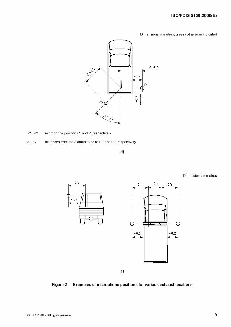
For vehicles for which the reference point of the exhaust pipe is not accessible or located under the vehicle body, as shown in Figures 2 c) and 2 d), because of the presence of obstacles that form part of the vehicle (e.g. spare wheel, fuel tank, battery compartment), the microphone shall be located at least 0,2 m from the nearest obstacle, including the vehicle body, and its axis of maximum sensitivity shall face the exhaust outlet from the position least concealed by the above-mentioned obstacles.
When several positions are possible, as shown in Figure 2 d), the microphone position giving the lowest value of d1 or d2 shall be used.

ISO/FDIS 5130:2006(E)
© ISO 2006 – All rights reserved 5
Figures 2 a) to 2 e) show examples of the position of the microphone, depending on the location of the exhaust pipe.
For the purpose of roadside checking, the reference point may be moved to the outer surface of the vehicle body.
Key 1 reference point 2 road surface
A mitered pipe B bent down pipe C straight pipe D vertical pipe
Figure 1 — Reference point

ISO/FDIS 5130:2006(E)
6 © ISO 2006 – All rights reserved
Dimensions in metres, unless otherwise indicated
a)

ISO/FDIS 5130:2006(E)
© ISO 2006 – All rights reserved 7
Dimensions in metres, unless otherwise indicated
b)

ISO/FDIS 5130:2006(E)
8 © ISO 2006 – All rights reserved
Dimensions in metres, unless otherwise indicated
c)
ISO/FDIS 5130:2006(E)
© ISO 2006 – All rights reserved 9
Dimensions in metres, unless otherwise indicated
P1, P2 microphone positions 1 and 2, respectively
d1, d2 distances from the exhaust pipe to P1 and P2, respectively
d)
Dimensions in metres
e)
Figure 2 — Examples of microphone positions for various exhaust locations

ISO/FDIS 5130:2006(E)
10 © ISO 2006 – All rights reserved
6.4 Target engine speed
6.4.1 General
If the vehicle cannot reach the engine speed as stated below, the target engine speed shall be 5 % below the maximum possible engine speed for the stationary test.
6.4.2 Vehicles of category L
The target engine speed shall be
⎯ 75 % of the rated engine speed, S, for vehicles with S u 5 000 min−1,
⎯ 50 % of the rated engine speed, S, for vehicles with S > 5 000 min−1,
with a tolerance of ± 5 %.
6.4.3 Vehicles of category M, N
The target engine speed shall be:
⎯ 75 % of the rated engine speed, S, for vehicles with S u 5 000 min−1,
⎯ 3750 min−1 for vehicles with a rated engine speed 5 000 < S < 7 500 min−1,
⎯ 50 % of the rated engine speed, S, for vehicles with S W 7 500 min−1,
with a tolerance of ± 5 %.
6.5 Engine operating conditions
The engine speed shall be gradually increased from idle to the target engine speed, not exceeding the tolerance band as given in 6.4.2 and or 6.4.3 and held constant. Then the throttle control shall be rapidly released and the engine speed shall be returned to idle. The sound pressure level shall be measured during a period consisting of constant engine speed of at least 1 s and throughout the entire deceleration period. The maximum sound level meter reading shall be taken as the test value.
The measurement shall be regarded as valid if the test engine speed does not deviate from the target engine speed by more than the tolerances given in 6.4.2 and 6.4.3, for at least 1 s.
6.6 Multi-mode exhaust system
Vehicles equipped with a multi-mode exhaust system and a manual exhaust mode control shall be tested with the mode switch in all positions.
7 Measurements
Measurements shall be made according to the microphone location(s) described in 6.3.
The maximum A-weighted sound pressure level indicated during the test shall be noted, mathematically rounded to the first significant figure before the decimal place (e.g. 92,4 shall be rounded to 92 while 92,5 shall be rounded to 93).
The test shall be repeated until three consecutive measurements that are within 2 dB of each other are obtained at each outlet.

ISO/FDIS 5130:2006(E)
© ISO 2006 – All rights reserved 11
The result for a given outlet is the arithmetic average of the three valid measurements, mathematically rounded as given above and shall be reported as the A-weighted sound pressure level, LArep, as given by Equation (1):
LArep = (LAmeas,1 + LAmeas,2 + LAmeas,3)/3 (1)
For vehicles equipped with multiple exhaust outlets, the sound pressure level reported LArep shall be for the outlet having the highest average sound pressure level.
8 Interpretation of results
The result of testing a vehicle in use may be interpreted by comparison with the results of the reference test in which the vehicle was tested using the same method, for instance during type approval.
9 Measurement uncertainty
The measurement procedure described in the preceding clauses is affected by several parameters that lead to variation in the resulting level observed for the same subject. The source and nature of these perturbations are not completely known and sometimes affect the end result in a non-predictable way. The uncertainty of results obtained from measurements according to this International Standard can be evaluated by the procedure given in the ISO Guide 98 (formerly designated “GUM”), or by inter-laboratory comparisons in accordance with ISO 5725 (all parts). Since extensive inter- and intra-laboratory data are not yet available, the procedure given in the ISO Guide 98 was followed to estimate the uncertainty associated with this International Standard. The uncertainties given below are based on existing statistical data, analysis of tolerances stated in this International Standard and engineering judgment. The uncertainties so determined are grouped as follows:
a) variations expected within the same test laboratory and slight variations in ambient conditions found within a single test series (run-to-run);
b) variations expected within the same test laboratory but with a variation in ambient conditions and equipment properties that can normally be expected during the year (day-to-day);
c) variations between test-laboratories where, apart from ambient conditions, also equipment, staff and road surface conditions are different (site-to-site).
If reported, the expanded uncertainty, together with the corresponding coverage factor for the stated coverage probability of 80 % as defined in the ISO Guide 98, shall be given. Information on the determination of the expanded uncertainty is given in Annex B.
NOTE Annex B gives a framework for an analysis based on ISO Guide 98 that can be used to conduct future research on measurement uncertainty for this International Standard.
These data are given in Table 1. The variability is given for a coverage probability of 80 %. The data express the variability of results for a certain measurement object and do not cover product variation.
Table 1 — Variability of measurement results for a coverage probability of 80 %
Run-to-run
dB
Day-to-day
dB
Site-to-site
dB
0,8 1,2 1,9
Until more specific knowledge is available, the data for site-to-site variability can be used in test reports to state the expanded measurement uncertainty for a coverage probability of 80 %.

ISO/FDIS 5130:2006(E)
12 © ISO 2006 – All rights reserved
Due to the uncertainty influence, differences between the sound pressure level of the vehicle in-use and that in corresponding reference tests should not be considered significant unless they are equal to or larger than 5 dB.
The variations in the sound pressure level of identical units of a production process are outside the scope of this International Standard. Such variation is within the scope of the quality control systems of the manufacturer.
10 Test report
The test report shall include the following information:
a) statement that the test was in accordance with ISO 5130;
b) test site, ground conditions, and weather conditions;
c) type of measuring equipment, including the windscreen;
d) A-weighted sound pressure level typical of the background noise;
e) identification of the vehicle, its engine and its transmission system;
f) general description of the location of the engine and exhaust outlet;
g) location and orientation of the microphone;
h) engine operating speed used for the test;
i) A-weighted sound pressure level, LArep, determined by the test.

ISO/FDIS 5130:2006(E)
© ISO 2006 – All rights reserved 13
Annex A (informative)
Technical background information
There are several technical reasons to revise ISO 5130:1982, dealing with the stationary test method developed in the late 1970s. Since the last revision of this procedure, there has been continuous development of vehicle technology, including the reduction of exhaust noise, and the design of vehicle exhaust systems.
The original scope of the procedure was to provide a simple method for use in roadside checks of exhaust systems, e.g. by the police or road authorities.
In some countries/regions, a general noise limit for different categories of vehicles has been introduced and control is performed to check for faults in the exhaust system. This application of the procedure causes inaccuracies for vehicles with rear- or mid-engine, as the engine noise can be the dominating noise source, thereby interfering with the intent of the measurement. In such cases, flexible shields are necessary to separate the different noise sources during the test, adding complexity and measurement variability.
Investigations have shown that the present method is not particularly suited to check the exhaust system against a general noise limit, because of the influence of other vehicle-noise sources at the position of the microphone. The extent to which other noise sources can contribute to the stationary measurement is vehicle-design dependent. These investigations also show that the noise close to the exhaust pipe is very much dependent on engine speed and can vary as much as 20 dB over a typical range of operating engine speeds. Because a vehicle exhaust system is an acoustic-tuning element, levels of noise do not necessarily increase in a linear fashion with increasing engine speed. Thus, it seems prudent to revise ISO 5130:1982, in order to more clearly define its scope and enhance the accuracy of the measurement method.
In several countries, for example the Member States of the European Union and Norway, a system has been introduced such that the stationary level of noise (measured during type approval or when imported as a used vehicle) is labelled in the vehicle-registration documents, which are kept with the vehicle. This concept provides a more efficient basis for spot checks of the performance of vehicles using a stationary test. Comparison of results of the level of noise obtained from a roadside, or periodic technical inspection, to the baseline level of noise obtained during type approval gives a more accurate measure of the performance of any given vehicle. It is recommended that this method be added to the scope of this procedure to improve the validity of its application.
ISO 5130:1982 contained an annex describing a close-proximity method for the measurement of stationary engine noise. This annex has been deleted, as there seems no need for such a method.

ISO/FDIS 5130:2006(E)
14 © ISO 2006 – All rights reserved
Annex B (informative)
Measurement uncertainty — Framework for uncertainty analysis
based on ISO Guide 98
B.1 General
The measurement procedure is affected by several disturbing factors that lead to variations in the resulting level observed for the same subject. The source and nature of these perturbations are not completely known and sometimes affect the end result in a non-predictable way. The accepted format for expression of uncertainties generally associated with methods of measurement is that given in the ISO Guide 98. This format incorporates an uncertainty budget, in which all the various sources of uncertainty are identified and quantified, from which the combined standard uncertainty can be obtained. Uncertainties are due to
⎯ variations in measurement devices, such as sound level meters, calibrators and engine speed measuring devices;
⎯ variations in local environmental conditions that affect sound propagation at the time of measurement;
⎯ variations in local environmental conditions that affect the characteristics of the source;
⎯ effect of environmental conditions that influence the mechanical characteristics of the source, mainly engine performance (air pressure, air density, humidity, air temperature);
⎯ test-site properties.
The uncertainty determined in accordance with Clause 9 represents the uncertainty associated with this International Standard. It does not cover the uncertainty associated with the variation in the production processes of the manufacturer. The variations in the exhaust sound pressure level of identical units of a production process are outside the scope of this International Standard.
The uncertainty effects may be grouped in the three categories arising from the following sources; see Clause 9:
a) uncertainty due to changes in vehicle operation within consecutive runs, small changes in weather conditions, small changes in background noise levels and measurement system uncertainty; referred to as run-to-run variations;
b) uncertainty due to changes in weather conditions throughout the year, changing properties of a test site over time, changes in measurement-system performance over longer periods and changes in the vehicle operation; referred to as day-to-day variations;
c) uncertainty due to different test-site locations, measurement systems and vehicle operation; referred to as site-to-site variations.
The site-to-site variation comprises uncertainty sources from a), b) and c). The day-to-day variation comprises uncertainty sources from a) and b).

ISO/FDIS 5130:2006(E)
© ISO 2006 – All rights reserved 15
B.2 Expression for the calculation of vehicle stationary exhaust operation sound pressure level
The general expression for the calculation of stationary exhaust sound pressure level, LArep, is given by Equation (B.1):
LArep = (LAmeas,1 + LAmeas,2 + LAmeas,3)/3 + δ1 + δ2 + δ3 + δ4 + δ5 + δ6 (B.1)
where
LArep is the reported A-weighted sound pressure level;
LAmeas,i is the A-weighted sound pressure level from each individual test, i;
δ1 is an input quantity to allow for any uncertainty in the measurement system;
δ2 is an input quantity to allow for any uncertainty in the environmental conditions that affect sound propagation from the source the time of measurement;
δ3 is an input quantity to allow for any uncertainty in the engine speed;
δ4 is an input quantity to allow for any uncertainty in the local environmental conditions that affect characteristics of the source;
δ5 is an input quantity to allow for any uncertainty in the effect of environmental conditions on the mechanical characteristics of the power unit;
δ6 is an input quantity to allow for any uncertainty in the effect of test site properties.
NOTE The inputs included in Equation (B.1) to allow for errors are those thought to be applicable in the state of knowledge at the time when this International Standard was being prepared, but further research can reveal that there are others.
B.3 Uncertainty budget
The estimated values of the delta functions can be principally positive or negative, although they are considered to be zero for the given measurement; see Table B.1. Their uncertainties are not additive for the purpose of determining a measurement result.
Table B.1 — Uncertainty budget for determination of reported sound pressure level
Quantity Estimate
dB
Standard uncertainty
ui
dB
Probability distribution
Sensitivity coefficient
ci
Uncertainty contribution
uici
dB
LAmeas,i LAmeas,i — — 1 —
δ1 0 — — 1 —
δ2 0 — — 1 —
δ3 0 — — 1 —
δ4 0 — — 1 —
δ5 0 — — 1 —
δ6 0 — — 1 —

ISO/FDIS 5130:2006(E)
16 © ISO 2006 – All rights reserved
From the individual uncertainty contributions, uici, the combined standard uncertainty, u, can be calculated according to the rules of ISO Guide 98, taking into account potential correlations between various input quantities.
NOTE The uncertainty evaluation described represents a framework that provides useful information to users of this International Standard. This information represents the state of technical information at this time. Further work is necessary to provide uncertainty information on all terms in Equation (B.1) and all interactions between such terms.
B.4 Expanded uncertainty of measurement
The expanded uncertainty, U, is calculated by multiplying the combined standard uncertainty, u, with the appropriate coverage factor for the chosen coverage probability, as described in ISO Guide 98.

ISO/FDIS 5130:2006(E)
© ISO 2006 – All rights reserved 17
Bibliography
[1] ISO 362-1:—, Measurement of noise emitted by accelerating road vehicles — Engineering method — Part 1: M and N categories
[2] SAE J1492:1998-05, Measurement of Light Vehicle Stationary Exhaust System Sound Level Engine Speed Sweep Method
[3] SAE J1287:1998-07, Measurement of Exhaust Sound Levels of Stationary Motorcycles
[4] ISO 80000-2 1), Quantities and units — Part 2: Mathematical signs and symbols to be used in the natural sciences and technology
1) Under preparation.

ISO/FDIS 5130:2006(E)
ICS 17.140.30; 43.020 Price based on 17 pages
© ISO 2006 – All rights reserved