filtri - filters · 2017-06-26 · afi filter series is suitable to the following iso...
TRANSCRIPT
SERIE AFI SERIES
Filtri in aspirazione e sul ritornoSuction or return filters F
iltri
-F
ilter
s0
6
Omt_AFI:Omt_AFI 17-02-2009 8:05 Pagina 1
FILTRI IN ASPIRAZIONE E SUL RITORNO SERIE AFI2.000.000 Pa (20 BAR)
SUCTION AND RETURN FILTER SERIES AFI2.000.000 Pa (20 BAR)
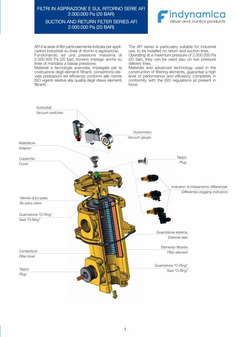
AFI è la serie di filtri particolarmente indicata per appli-cazioni industriali su linee di ritorno e aspirazione.Funzionando ad una pressione massima di2.000.000 Pa (20 bar), trovano impiego anche sulinee di mandata a bassa pressione.Materiali e tecnologie avanzate, impiegate per lacostruzione degli elementi filtranti, consentono ele-vate prestazioni ed efficienza conformi alle normeISO vigenti relative alla qualità degli stessi elementifiltranti.
The AFI series is particulary suitable for industrialuse, to be installed on return and suction lines.Operating at a maximum pressure of 2.000.000 Pa(20 bar), they can be used also on low pressuredelivery lines.Materials and advanced technology used in theconstruction of filtering elements, guarantee a highlevel of performance and efficiency completely inconformity with the ISO regulations at present inforce.
Valvola di by-passBy-pass valve
Guarnizione “O-Ring”Seal “O-Ring”
Elemento filtranteFilter element
CoperchioCover
Guarnizione “O-Ring”Seal “O-Ring”
Guarnizione esternaExternal seal
ContenitoreFilter bowl
TappoPlug
TappoPlug
Indicatori di intasamento differenzialiDifferential clogging indicators
VuotometroVacuum gauge
VuotostatiVacuum switches
AdattatoreAdaptor
1
Omt_AFI:Omt_AFI 17-02-2009 8:05 Pagina 3
2
CARATTERISTICHE TECNICHETECHNICAL DATA
LA SERIE DI FILTRI AFI ÈCONFORME ALLE SEGUENTI NORME ISO:
-ISO 2941 - Oleoidraulica - Elementi filtranti - Verifica dellaresistenza allo schiacciamento o allo scoppio
-ISO 2942 - Oleoidraulica - Elementi filtranti - Verificadell’integrità di fabbricazione e determinazionedel punto di prima bolla
-ISO 2943 - Oleoidraulica - Elementi filtranti - Verifica dellacompatibilità dei materiali con i fluidi
-ISO 3723 - Oleoidraulica - Elementi filtranti - Verifica dellaresistenza alla deformazione assiale
-ISO 3724 - Oleoidraulica - Elementi filtranti - Verifica dellaresistenza a fatica per variazioni di portata
-ISO 3968 - Oleoidraulica - Filtri - Determinazione dellaperdita di carico in funzione della portata
-ISO 16889 - Oleoidraulica - Filtri - Metodo Multi-passvalutazione delle caratteristiche di filtrazionedi un elemento filtrante
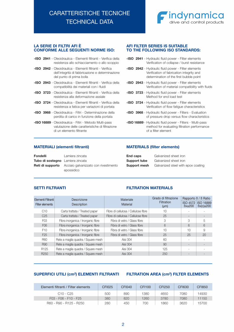
MATERIALI (elementi filtranti)
Fondelli Lamiera zincataTubo di sostegno Lamiera zincataReti di supporto Acciaio galvanizzato con rivestimento
epossidico
C10 Carta trattata / Treated paper Fibre di cellulosa / Cellulose fibre 10 - -C25 Carta trattata / Treated paper Fibre di cellulosa / Cellulose fibre 25 - -F03 Fibra inorganica / Inorganic fibre Fibra di vetro / Glass fibre 3 3 5F06 Fibra inorganica / Inorganic fibre Fibra di vetro / Glass fibre 6 6 6F10 Fibra inorganica / Inorganic fibre Fibra di vetro / Glass fibre 10 10 9F25 Fibra inorganica / Inorganic fibre Fibra di vetro / Glass fibre 25 25 20R60 Rete a maglia quadra / Square mesh Aisi 304 60 - -R90 Rete a maglia quadra / Square mesh Aisi 304 90 - -R125 Rete a maglia quadra / Square mesh Aisi 304 125 - -R250 Rete a maglia quadra / Square mesh Aisi 304 250 - -
Elementi FiltrantiFilter elements
DescrizioneDescription
MaterialeMaterial
Grado di filtrazioneFiltration
(μm)
Rapporto ß / ß RatioISO 4572ßx≥200
ISO 16889ßx(c)≥200
MATERIALS (filter elements)
End caps Galvanized sheet ironSupport tube Galvanized sheet ironSupport mesh Galvanized steel with epox coating
SETTI FILTRANTI FILTRATION MATERIALS
SUPERFICI UTILI (cm2) ELEMENTI FILTRANTI FILTRATION AREA (cm2) FILTER ELEMENTS
AFI FILTER SERIES IS SUITABLETO THE FOLLOWING ISO STANDARDS:
-ISO 2941 - Hydraulic fluid power - Filter elementsVerification of collapse / burst resistance
-ISO 2942 - Hydraulic fluid power - Filter elementsVerification of fabrication integrity anddetermination of the first bubble point
-ISO 2943 - Hydraulic fluid power - Filter elementsVerification of material compatibility with fluids
-ISO 3723 - Hydraulic fluid power - Filter elementsMethod for end load test
-ISO 3724 - Hydraulic fluid power - Filter elementsVerification of flow fatigue characteristics
-ISO 3968 - Hydraulic fluid power - Filters - Evaluationof pressure drop versus flow characteristics
-ISO 16889 - Hydraulic fluid power - Filters - Multi-passmethod for evaluating filtration performanceof a filter element
Elementi filtranti / Filter elements CFI025 CFI040 CFI100 CFI250 CFI630 CFI850
C10 - C25 500 890 1380 4650 7080 14930F03 - F06 - F10 - F25 380 820 1260 3780 7080 11150
R60 - R90 - R125 - R250 280 450 700 1860 3620 15700
Omt_AFI:Omt_AFI 17-02-2009 8:05 Pagina 4
VS-30
VALVOLA DI MASSIMA PRESSIONEDIRECT POPPET TYPE RELIEF
3
CARATTERISTICHE TECNICHETECHNICAL DATA
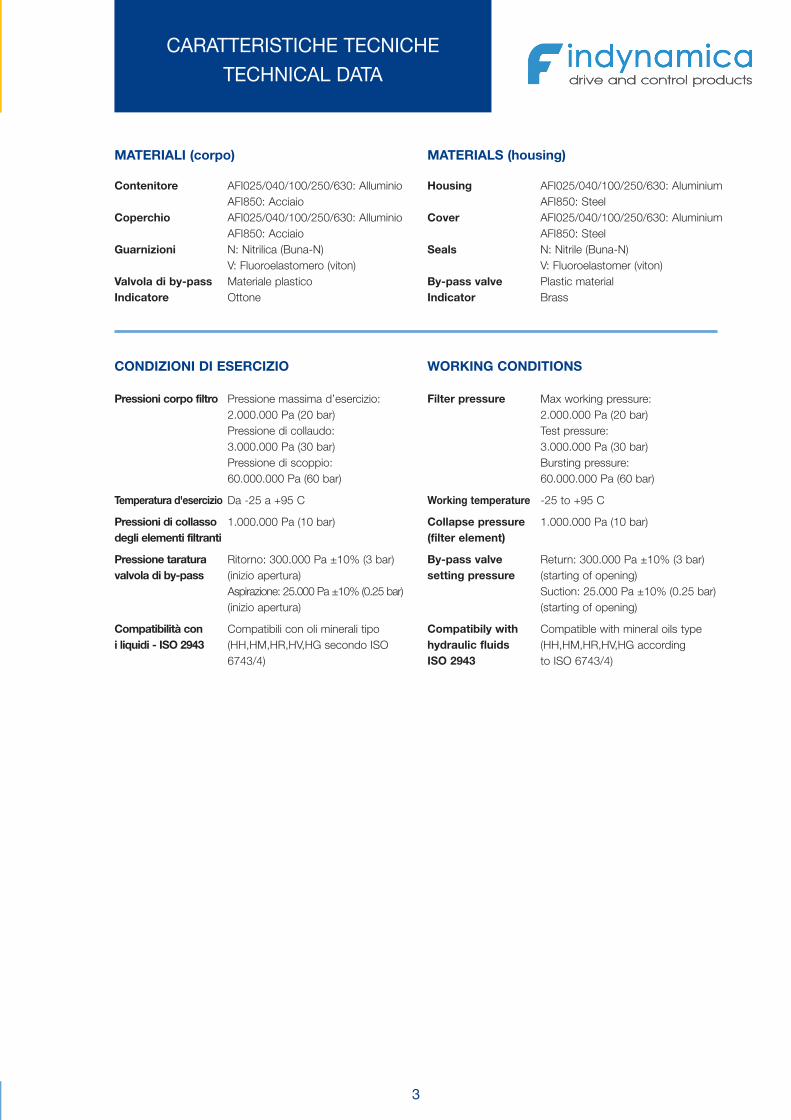
MATERIALI (corpo)
Contenitore AFI025/040/100/250/630: AlluminioAFI850: Acciaio
Coperchio AFI025/040/100/250/630: AlluminioAFI850: Acciaio
Guarnizioni N: Nitrilica (Buna-N)V: Fluoroelastomero (viton)
Valvola di by-pass Materiale plasticoIndicatore Ottone
MATERIALS (housing)
Housing AFI025/040/100/250/630: AluminiumAFI850: Steel
Cover AFI025/040/100/250/630: AluminiumAFI850: Steel
Seals N: Nitrile (Buna-N)V: Fluoroelastomer (viton)
By-pass valve Plastic materialIndicator Brass
CONDIZIONI DI ESERCIZIO
Pressioni corpo filtro
Temperatura d'esercizio
Pressioni di collassodegli elementi filtranti
Pressione taraturavalvola di by-pass
Compatibilità coni liquidi - ISO 2943
Pressione massima d’esercizio:2.000.000 Pa (20 bar)Pressione di collaudo:3.000.000 Pa (30 bar)Pressione di scoppio:60.000.000 Pa (60 bar)
Da -25 a +95 C
1.000.000 Pa (10 bar)
Ritorno: 300.000 Pa ±10% (3 bar)(inizio apertura)Aspirazione: 25.000 Pa ±10% (0.25 bar)(inizio apertura)
Compatibili con oli minerali tipo(HH,HM,HR,HV,HG secondo ISO6743/4)
WORKING CONDITIONS
Filter pressure
Working temperature
Collapse pressure(filter element)
By-pass valvesetting pressure
Compatibily withhydraulic fluidsISO 2943
Max working pressure:2.000.000 Pa (20 bar)Test pressure:3.000.000 Pa (30 bar)Bursting pressure:60.000.000 Pa (60 bar)
-25 to +95 C
1.000.000 Pa (10 bar)
Return: 300.000 Pa ±10% (3 bar)(starting of opening)Suction: 25.000 Pa ±10% (0.25 bar)(starting of opening)
Compatible with mineral oils type(HH,HM,HR,HV,HG accordingto ISO 6743/4)
Omt_AFI:Omt_AFI 17-02-2009 8:05 Pagina 5

4
AFI series 025
Le portate sono state calcolate per avere una per-dita di carico Δp ≤60.000 Pa (0.6 bar) per i filtri sulritorno e Δp ≤5.000 Pa (0.05 bar) per i filtri in aspi-razione.I valori sono stati ottenuti con olio Minerale aventeviscosità cinematica 30 cSt e densità 860 kg/m3.(vedi note a pag. 10)
Flows have been calculated just in order to obtaina pressure drop Δp ≤60.000 Pa (0.6 bar) for returnlines and Δp ≤5.000 Pa (0.05 bar) for suction lines.The values have been obtained using mineral oilkinematic viscosity 30 cSt and 860 kg/m3 density.(See remarks on pag.10)
025 C10 - 40 0,750025 C25 - 40 0,750025 F03 - 8 0,750025 F06 - 12 0,750025 F10 - 28 0,750025 F25 - 39 0,750025 R60 30 40 0,750025 R90 32 40 0,750025 R125 / R250 35 40 0,750
AFIElementofiltrante
Filter element
Portata / Flow (L/min)
AspirazioneSuction
RitornoReturn
PesoWeight
(kg)
PORTATE CONSIGLIATERECOMMENDED FLOWS
025 1/2” BSP025 1/2” NPT025 SAE 8-3/4” - 16 UNF
CodiceCode
A
ATTACCHI FILETTATITHREADED CONNECTIONS
Ch. 4
Ch. 30
ø95
98ø
N°4 fori ø6
0° 9
941
47
ø83.5
44
02
5.26
A
501
.T.M.
O
Ch. 10
A (Tappo / Plug)
Omt_AFI:Omt_AFI 17-02-2009 8:05 Pagina 6
5
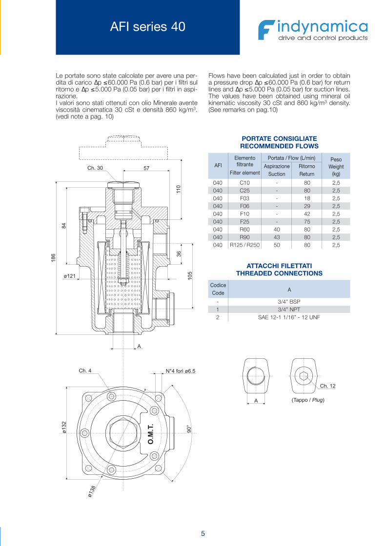
AFI series 40
Le portate sono state calcolate per avere una per-dita di carico Δp ≤60.000 Pa (0.6 bar) per i filtri sulritorno e Δp ≤5.000 Pa (0.05 bar) per i filtri in aspi-razione.I valori sono stati ottenuti con olio Minerale aventeviscosità cinematica 30 cSt e densità 860 kg/m3.(vedi note a pag. 10)
Flows have been calculated just in order to obtaina pressure drop Δp ≤60.000 Pa (0.6 bar) for returnlines and Δp ≤5.000 Pa (0.05 bar) for suction lines.The values have been obtained using mineral oilkinematic viscosity 30 cSt and 860 kg/m3 density.(See remarks on pag.10)
040 C10 - 80 2,5040 C25 - 80 2,5040 F03 - 18 2,5040 F06 - 29 2,5040 F10 - 42 2,5040 F25 - 75 2,5040 R60 40 80 2,5040 R90 43 80 2,5040 R125 / R250 50 80 2,5
AFIElementofiltrante
Filter element
Portata / Flow (L/min)
AspirazioneSuction
RitornoReturn
PesoWeight
(kg)
PORTATE CONSIGLIATERECOMMENDED FLOWS
- 3/4” BSP1 3/4” NPT2 SAE 12-1 1/16” - 12 UNF
CodiceCode
A
ATTACCHI FILETTATITHREADED CONNECTIONS
Ch. 4
Ch. 30
38ø1
231ø
N°4 fori ø6.5
90°
681
48
ø121
57
63
501
A
011
.T.M.
O
Ch. 12
A (Tappo / Plug)
Omt_AFI:Omt_AFI 17-02-2009 8:05 Pagina 7
6
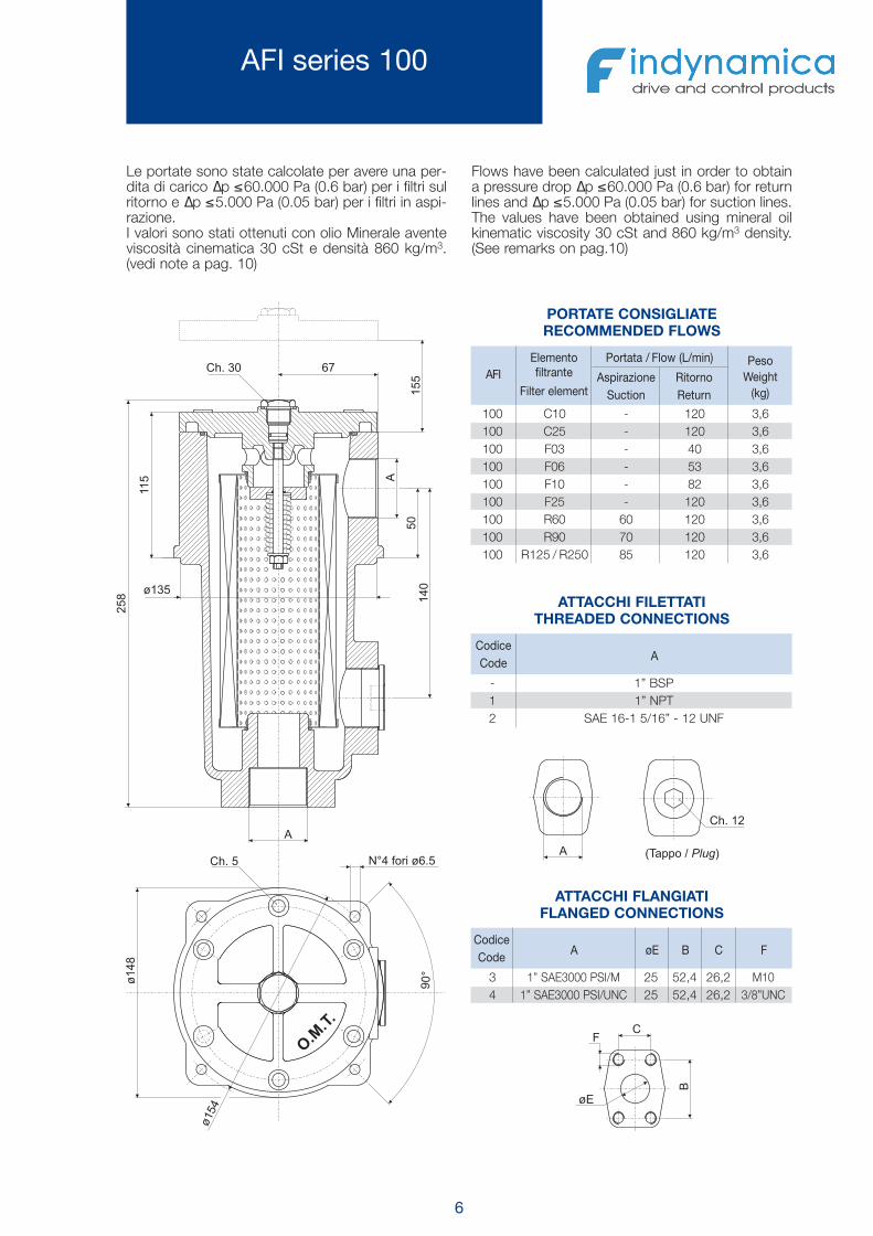
AFI series 100
Le portate sono state calcolate per avere una per-dita di carico Δp ≤60.000 Pa (0.6 bar) per i filtri sulritorno e Δp ≤5.000 Pa (0.05 bar) per i filtri in aspi-razione.I valori sono stati ottenuti con olio Minerale aventeviscosità cinematica 30 cSt e densità 860 kg/m3.(vedi note a pag. 10)
Flows have been calculated just in order to obtaina pressure drop Δp ≤60.000 Pa (0.6 bar) for returnlines and Δp ≤5.000 Pa (0.05 bar) for suction lines.The values have been obtained using mineral oilkinematic viscosity 30 cSt and 860 kg/m3 density.(See remarks on pag.10)
100 C10 - 120 3,6100 C25 - 120 3,6100 F03 - 40 3,6100 F06 - 53 3,6100 F10 - 82 3,6100 F25 - 120 3,6100 R60 60 120 3,6100 R90 70 120 3,6100 R125 / R250 85 120 3,6
AFIElementofiltrante
Filter element
Portata / Flow (L/min)
AspirazioneSuction
RitornoReturn
PesoWeight
(kg)
PORTATE CONSIGLIATERECOMMENDED FLOWS
- 1” BSP1 1” NPT2 SAE 16-1 5/16” - 12 UNF
CodiceCode
A
ATTACCHI FILETTATITHREADED CONNECTIONS
3 1” SAE3000 PSI/M 25 52,4 26,2 M104 1” SAE3000 PSI/UNC 25 52,4 26,2 3/8”UNC
CodiceCode
A øE B C F
ATTACCHI FLANGIATIFLANGED CONNECTIONS
Ch. 30
041
A
A
05
67
511
852
551
Ch. 5
90°
841ø
N°4 fori ø6.5
ø154
ø135
O.M.T.
Ch. 12
A (Tappo / Plug)
B
CF
øE
Omt_AFI:Omt_AFI 17-02-2009 8:05 Pagina 8

7
AFI series 250
Le portate sono state calcolate per avere una per-dita di carico Δp ≤60.000 Pa (0.6 bar) per i filtri sulritorno e Δp ≤5.000 Pa (0.05 bar) per i filtri in aspi-razione.I valori sono stati ottenuti con olio Minerale aventeviscosità cinematica 30 cSt e densità 860 kg/m3.(vedi note a pag. 10)
Flows have been calculated just in order to obtaina pressure drop Δp ≤60.000 Pa (0.6 bar) for returnlines and Δp ≤5.000 Pa (0.05 bar) for suction lines.The values have been obtained using mineral oilkinematic viscosity 30 cSt and 860 Kg/m3 density.(See remarks on pag.10)
250 C10 - 300 5,2250 C25 - 300 5,2250 F03 - 120 5,2250 F06 - 190 5,2250 F10 - 250 5,2250 F25 - 300 5,2250 R60 110 300 5,2250 R90 130 300 5,2250 R125 / R250 150 300 5,2
AFIElementofiltrante
Filter element
Portata / Flow (L/min)
AspirazioneSuction
RitornoReturn
PesoWeight
(kg)
PORTATE CONSIGLIATERECOMMENDED FLOWS
- 1 1/2” BSP1 1 1/2” NPT2 SAE 24-1 7/8” - 12 UNF
CodiceCode
A
ATTACCHI FILETTATITHREADED CONNECTIONS
3 1 1/2” SAE3000 PSI/M 38 70 35,7 M104 1 1/2” SAE3000 PSI/UNC 38 70 35,7 1/2”UNC
CodiceCode
A øE B C F
ATTACCHI FLANGIATIFLANGED CONNECTIONS
Ch. 30
Ch. 8
471
A
A
0°9
471ø
N°4 fori ø8.5
85
82
621
043
ø180
042
ø162
O.M
.T.
Ch. 14
A (Tappo / Plug )
B
CF
øE
Omt_AFI:Omt_AFI 17-02-2009 8:05 Pagina 9

8
AFI series 630
Le portate sono state calcolate per avere una per-dita di carico Δp ≤60.000 Pa (0.6 bar) per i filtri sulritorno e Δp ≤5.000 Pa (0.05 bar) per i filtri in aspi-razione.I valori sono stati ottenuti con olio Minerale aventeviscosità cinematica 30 cSt e densità 860 kg/m3.(vedi note a pag. 10)
Flows have been calculated just in order to obtaina pressure drop Δp ≤60.000 Pa (0.6 bar) for returnlines and Δp ≤5.000 Pa (0.05 bar) for suction lines.The values have been obtained using mineral oilkinematic viscosity 30 cSt and 860 kg/m3 density.(See remarks on pag.10)
630 C10 - 650 13630 C25 - 650 13630 F03 - 210 13630 F06 - 370 13630 F10 - 430 13630 F25 - 570 13630 R60 200 650 13630 R90 230 650 13630 R125 / R250 270 650 13
AFIElementofiltrante
Filter element
Portata / Flow (L/min)
AspirazioneSuction
RitornoReturn
PesoWeight
(kg)
PORTATE CONSIGLIATERECOMMENDED FLOWS
- 2 1/2” BSP1 2 1/2” NPT2 SAE 32-2 1/2” - 12 UNF
CodiceCode
A
ATTACCHI FILETTATITHREADED CONNECTIONS
3 2 1/2” SAE3000 PSI/M 63 89 50,8 M124 2 1/2” SAE3000 PSI/UNC 63 89 50,8 1/2”UNC
CodiceCode
A øE B C F
ATTACCHI FLANGIATIFLANGED CONNECTIONS
O.M.T.
Ch. 30
Ch. 8
81297
ø236.5
593
N°4 Fori ø10.5
09°
117
161 A
A
ø725
352ø
082
Ch. 14
A (Tappo / Plug)
B
C
F
øE
Omt_AFI:Omt_AFI 17-02-2009 8:05 Pagina 10

9
AFI series 850
Le portate sono state calcolate per avere una per-dita di carico Δp ≤60.000 Pa (0.6 bar) per i filtri sulritorno e Δp ≤5.000 Pa (0.05 bar) per i filtri in aspi-razione.I valori sono stati ottenuti con olio Minerale aventeviscosità cinematica 30 cSt e densità 860 kg/m3.(vedi note a pag. 10)
Flows have been calculated just in order to obtaina pressure drop Δp ≤60.000 Pa (0.6 bar) for returnlines and Δp ≤5.000 Pa (0.05 bar) for suction lines.The values have been obtained using mineral oilkinematic viscosity 30 cSt and 860 Kg/m3 density.(See remarks on pag.10)
850 C10 - 1100 48850 C25 - 1200 48850 F03 - 540 48850 F06 - 740 48850 F10 - 950 48850 F25 - 1000 48850 R60 400 1200 48850 R90 470 1200 48850 R125 / R250 550 1200 48
AFIElementofiltrante
Filter element
Portata / Flow (L/min)
AspirazioneSuction
RitornoReturn
PesoWeight
(kg)
PORTATE CONSIGLIATERECOMMENDED FLOWS
- 3 1/2” SAE3000 PSI/M 89 120,7 70 M161 3 1/2” SAE3000 PSI/UNC 89 120,7 70 5/8”UNC
CodiceCode
A øE B C F
ATTACCHI FLANGIATIFLANGED CONNECTIONS
Ch. 30
Ch. 8
A
A
178
90°572
ø
N°4 Fori ø14.5
ø236
821
542
586003
ø
525
O.M.T.
B
CF
øE
Omt_AFI:Omt_AFI 17-02-2009 8:05 Pagina 11
10
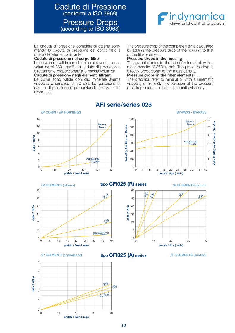
Cadute di Pressione(conformi a ISO 3968)
Pressure Drops(according to ISO 3968)
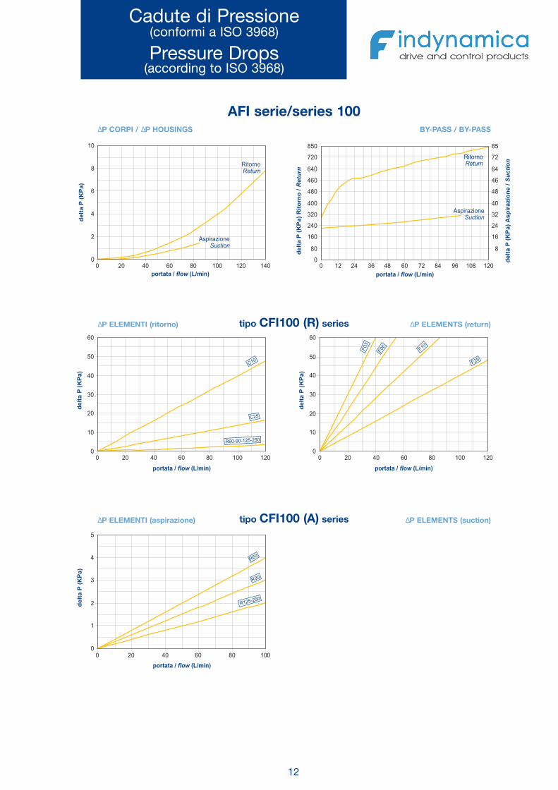
La caduta di pressione completa si ottiene som-mando la caduta di pressione del corpo filtro equella dell’elemento filtrante.Cadute di pressione nel corpo filtroLe curve sono valide con olio minerale avente massavolumica di 860 kg/m3. La caduta di pressione èdirettamente proporzionale alla massa volumica.Cadute di pressione negli elementi filtrantiLe curve sono valide con olio minerale aventeviscosità cinematica di 30 cSt. La variazione dicaduta di pressione è proporzionale alla viscositàcinematica.
The pressure drop of the complete filter is calculatedby adding the pressure drop of the housing to thatof the filter element.Pressure drops in the housingThe graphics refer to the use of mineral oil with amass density of 860 kg/m3. The pressure drop isdirectly proportional to the mass density.Pressure drops in the filter elementsThe graphics refer to mineral oil with a kinematicviscosity of 30 cSt. The variation of the pressuredrop is proportional to the kinematic viscosity.
2
0
4
6
8
10
12
14
portata / flow (L/min)
)a
PK(
Patl
ed
0 10 20 30 40 50 0 4 8 12 16 20 24 28 32 36 400
100 10
200 20
300 30
400 40
500 50
600 60
portata / flow (L/min)
/o
nroti
R)
aP
K(P
atle
dnr
uteR
0
10
20
30
40
40
50
0 5 10 15 20 25 30 35 40 0 10 20 30 40
0 10 20 30 40
portata / flow (L/min)
)a
PK(
Patl
ed
0
10
20
30
40
50
60
portata / flow (L/min)
)a
PK(
Patl
ed
0
1
2
4
3
5
portata / flow (L/min)
)a
PK(
Patl
ed
RitornoReturn
06 0 1 5 20 9 - 2 - 5R -
R125- 025
RitornoReturn
AspirazioneSuction
AspirazioneSuction
01C
C25
F03
F06 F
01
F25
6R 0
9R 0
/e
noiz
arip
sA
)a
PK(
Patl
ed
noit
cuS
ΔP CORPI / ΔP HOUSINGS BY-PASS / BY-PASS
ΔP ELEMENTI (ritorno) ΔP ELEMENTS (return)
ΔP ELEMENTI (aspirazione) ΔP ELEMENTS (suction)
tipo CFI025 (R) series
tipo CFI025 (A) series
AFI serie/series 025
Omt_AFI:Omt_AFI 17-02-2009 8:05 Pagina 12
11
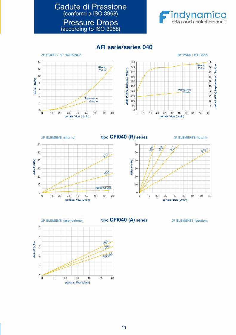
Cadute di Pressione(conformi a ISO 3968)
Pressure Drops(according to ISO 3968)
portata / flow (L/min)
2
0
4
6
8
10
12
14
)a
PK(
Patl
ed
0 10 20 30 40 50 60 70 80
0 10 20 30 40 50 60 70 80 0 10 20 30 40 50 60 70 80
0 10 20 30 40 50 60
0 8 16 24 32 40 48 56 64 72 80
0
10
20
30
40
60
50
portata / flow (L/min)
)a
PK(
Patl
ed
0
10
20
30
40
60
50
portata / flow (L/min)
)a
PK(
Patl
ed
0
1
2
4
3
5
portata / flow (L/min)
)a
PK(
Patl
ed
AspirazioneSuction
C01
RitornoReturn
portata / flow (L/min)
0
80 8
160 16
320 32
240 24
400 40
560 56
480 48
640 64
720 72
800 80
AspirazioneSuction
RitornoReturn
C 52
R - - 25-2560 90 1 0
3F
0 06F F10
F25
512 0
2 - 5R
60R
C90
/o
nroti
R)
aP
K(P
atle
dnr
uteR /
en
oizari
ps
A)
aP
K(P
atle
dnoit
cuS
ΔP CORPI / ΔP HOUSINGS BY-PASS / BY-PASS
ΔP ELEMENTI (ritorno) ΔP ELEMENTS (return)
ΔP ELEMENTI (aspirazione) ΔP ELEMENTS (suction)
tipo CFI040 (R) series
tipo CFI040 (A) series
AFI serie/series 040
Omt_AFI:Omt_AFI 17-02-2009 8:05 Pagina 13
12
Cadute di Pressione(conformi a ISO 3968)
Pressure Drops(according to ISO 3968)
portata / flow (L/min)
0
2
4
6
8
10
)a
PK(
Patl
ed
0 20 40 60 80 100 120 140
0 20 40 60 80 100 120
0 20 40 60 80 100
0 20 40 60 80 100 120
0 12 24 36 48 60 72 84 96 108 120
0
1
2
3
4
5
portata / flow (L/min)
)a
PK(
Patl
ed
0
10
20
30
40
60
50
portata / flow (L/min)
)a
PK(
Patl
ed
0
10
20
30
40
60
50
portata / flow (L/min)
)a
PK(
Patl
ed
RitornoReturn
AspirazioneSuction
0
80 8
160 16
240 24
320 32
400 40
480 48
850 85
720 72
640 64
460 46
portata / flow (L/min)
AspirazioneSuction
RitornoReturn
6 9 -2- -1 5 0R 0 0 2 5
C25
1C0
F03
F06
F10
2F 5
60R
R 09
-2 2 0R 51
5
/o
nroti
R)
aP
K(P
atle
dnr
uteR /
en
oizari
ps
A)
aP
K(P
atle
dnoit
cuS
ΔP CORPI / ΔP HOUSINGS BY-PASS / BY-PASS
ΔP ELEMENTI (ritorno) ΔP ELEMENTS (return)
ΔP ELEMENTI (aspirazione) ΔP ELEMENTS (suction)
tipo CFI100 (R) series
tipo CFI100 (A) series
AFI serie/series 100
Omt_AFI:Omt_AFI 17-02-2009 8:05 Pagina 14

13
Cadute di Pressione(conformi a ISO 3968)
Pressure Drops(according to ISO 3968)
portata / flow (L/min)
0
2
4
6
8
10
)a
PK(
Patl
ed
0 30 60 90 120 150 180 210 240 270 300
0 30 60 90 120 150 180 210 240 270 320
0 30 60 90 120 150
0 30 60 90 120 150 180 210 240 270 300
0 30 60 90 120 150 180 210 240 270 3000
10
20
30
40
60
50
portata / flow (L/min)
)a
PK(
Patl
ed
0
10
20
30
40
60
50
portata / flow (L/min)
)a
PK(
Patl
ed
0
1
2
4
3
5
portata / flow (L/min)
)a
PK(
Patl
ed
25C
RitornoReturn
AspirazioneSuction
0
100 10
200 20
400 40
300 30
600 60
500 50
700 70
900 90
800 80
1000 100
portata / flow (L/min)
AspirazioneSuction
RitornoReturn
F03
F60 F
01
F25
C 09
R60
-R 2 51 5 02
R - - 5 250 90 126 - 0
C10
/o
nroti
R)
aP
K(P
atle
dnr
uteR /
en
oizari
ps
A)
aP
K(P
atle
dnoit
cuS
ΔP CORPI / ΔP HOUSINGS BY-PASS / BY-PASS
ΔP ELEMENTI (ritorno) ΔP ELEMENTS (return)
ΔP ELEMENTI (aspirazione) ΔP ELEMENTS (suction)
tipo CFI250 (R) series
tipo CFI250 (A) series
AFI serie/series 250
Omt_AFI:Omt_AFI 17-02-2009 8:05 Pagina 15

14
Cadute di Pressione(conformi a ISO 3968)
Pressure Drops(according to ISO 3968)
portata / flow (L/min)
2
0
4
6
8
10
12
14
)a
PK(
Patl
ed
0 70 140 210 280 350 420 490 560 630 700
0 70 140 210 280 350 420 490 560 630 700
0 30 60 90 120 150 180 210 240 270 300
0 60 120 180 240 300 360 420 480 540 600
0 70 140 210 280 350 420 490 560 630 700
0
10
20
30
40
60
50
portata / flow (L/min)
)a
PK(
Patl
ed
0
10
20
30
40
60
50
portata / flow (L/min)
)a
PK(
Patl
ed
0
1
2
3
4
5
portata / flow (L/min)
)a
PK(
Patl
ed
AspirazioneSuction
RitornoReturn
portata / flow (L/min)
0
100 10
200 20
300 30
400 40
500 50
AspirazioneSuction
RitornoReturn
10C
25C
25-R 25060-90-1
03F
0F6
10F
2F5
2 - 52 0R1 5
90R
R60
/o
nroti
R)
aP
K(P
atle
dnr
uteR /
en
oizari
ps
A)
aP
K(P
atle
dnoit
cuS
ΔP CORPI / ΔP HOUSINGS BY-PASS / BY-PASS
ΔP ELEMENTI (ritorno) ΔP ELEMENTS (return)
ΔP ELEMENTI (aspirazione) ΔP ELEMENTS (suction)
tipo CFI630 (R) series
tipo CFI630 (A) series
AFI serie/series 630
Omt_AFI:Omt_AFI 17-02-2009 8:05 Pagina 16

15
Cadute di Pressione(conformi a ISO 3968)
Pressure Drops(according to ISO 3968)
portata / flow (L/min)
2
0
4
6
8
10
12
)a
PK(
Patl
ed
0 120 240 360 480 600 720 840 960 1080 1200
0 120 240 360 480 600 720 840 960 1080 1200
0 60 120 180 240 300 360 420 480 540 600
0 100 200 300 400 500 600 700 800 900 1000
0 120 240 360 480 600 720 840 960 1080 1200
0
10
20
30
40
60
50
portata / flow (L/min)
)a
PK(
Patl
ed
0
10
20
30
40
60
50
portata / flow (L/min)
)a
PK(
Patl
ed
0
1
2
4
3
5
portata / flow (L/min)
)a
PK(
Patl
ed
RitornoReturn
AspirazioneSuction
0
120 12
240 24
360 36
480 48
600 60
portata / flow (L/min)
RitornoReturn
AspirazioneSuction
C01
C25
0- 12 50R 9 5-6 0- 2
03F 0F6 F
01
F25
125-R
250
90R
R60
/o
nroti
R)
aP
K(P
atle
dnr
uteR /
en
oizari
ps
A)
aP
K(P
atle
dnoit
cuS
ΔP CORPI / ΔP HOUSINGS BY-PASS / BY-PASS
ΔP ELEMENTI (ritorno) ΔP ELEMENTS (return)
ΔP ELEMENTI (aspirazione) ΔP ELEMENTS (suction)
tipo CFI850 (R) series
tipo CFI850 (A) series
AFI serie/series 850
Omt_AFI:Omt_AFI 17-02-2009 8:05 Pagina 17

16
O M T
ø 16
45
07
1/2”BSPCH 30
O M T
1/2”BSPCH 30
ø 16
CH 30
2482
ø 16
1/2”BSP
O M T
B B
A A
AFI...R AFI...R + DV200 AFI...R + DE200 / DR200
B B
A A
3
2
1
N.A.
N.C.
C
B
AN.A.
N.C.
C
B
A
3
2
1
AFI...S AFI...S + DV200 AFI...S + DE200 / DR200
INDICATORI DI INTASAMENTO DIFFERENZIALIPER LINEE DI RITORNO
RETURN LINES CLOGGING INDICATORS
DV 200
INDICATORE VISIVOVISUAL INDICATOR
Con By-pass / With By-pass Senza By-pass / Without By-pass
INDICATORE VISIVO-ELETTRICOELECTRICAL VISUAL INDICATOR
INDICATORE VISIVO-ELETTRICOCON CONTATTI “REED”
VISUAL-ELECTRICAL INDICATORWITH “REED” CONTACTS
DE 200 DR 200
CodicePart number
DescrizioneDescription
TaraturaSetting
Contatti elettriciElectrical Contacts
D V 200 visivo / visual
200.000Pa(2 bar)
-
D E 200 visivo- elettricoelectrical-visual
D R 200visivo- elettrico
con contatti “reed”Visual-electrical
with “reed” contacts
ScambioChangeover
CARATTERISTICHE TECNICHETECHNICAL DATA
SIMBOLOGIASIMBOLOGY
A.C. 3-115 20D.C. 3-115 20
Tensioni di rottura per DR200Breakdown voltage for DR200
Tensione di alimen. (V)Feeder voltage (V)
Potenza con carico induttivo (VA)Power with inductive load (VA)
Tensioni di rottura per DE200Breakdown voltage for DE200
Tensione di alimen. (V)Feeder voltage (V)
Carico resistivo (A)Resistive load (A)
Carico induttivo (A)Inductive load (A)
C.A. 125 5 5C.A. 250 5 5C.C. 15 10 10C.C. 30 5 5C.C. 50 2 2C.C. 125 0.5 0.06
Omt_AFI:Omt_AFI 17-02-2009 8:05 Pagina 18
17
1/4"BSP
67
64
87
30x30
Ch.14
1/4"BSP
ø50
23
1/4"BSP
86
48
Ch.24
VV 2
VE 2 2
1
VE 3
3
A B
AFI.......A
N.C.N.C.
N.A.N.A.C
Vista dei contatti dall’altoTop view of contacts
Ch. 30
1/2"BSP
1/4"BSP
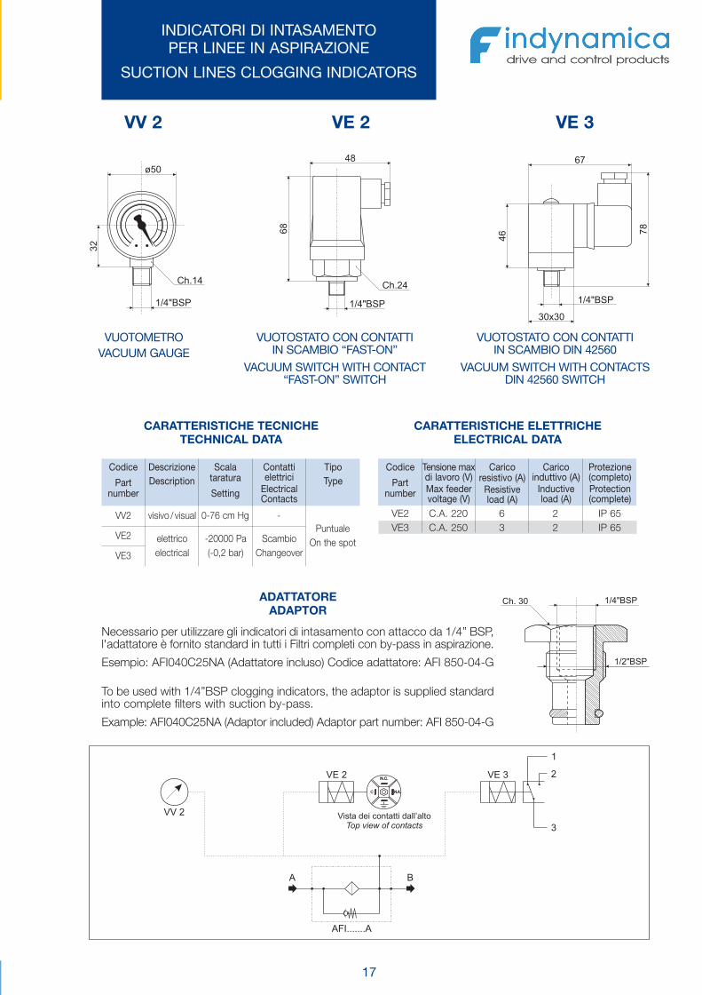
INDICATORI DI INTASAMENTOPER LINEE IN ASPIRAZIONE
SUCTION LINES CLOGGING INDICATORS
VUOTOMETROVACUUM GAUGE
VUOTOSTATO CON CONTATTIIN SCAMBIO “FAST-ON”
VACUUM SWITCH WITH CONTACT“FAST-ON” SWITCH
VUOTOSTATO CON CONTATTIIN SCAMBIO DIN 42560
VACUUM SWITCH WITH CONTACTSDIN 42560 SWITCH
VV 2 VE 2 VE 3
CARATTERISTICHE TECNICHETECHNICAL DATA
ADATTATOREADAPTOR
CARATTERISTICHE ELETTRICHEELECTRICAL DATA
VE2 C.A. 220 6 2 IP 65VE3 C.A. 250 3 2 IP 65
Codice
Partnumber
DescrizioneDescription
Scalataratura
Setting
Contattielettrici
ElectricalContacts
TipoType
Codice
Partnumber
Tensione maxdi lavoro (V)Max feedervoltage (V)
Caricoresistivo (A)
Resistiveload (A)
Caricoinduttivo (A)
Inductiveload (A)
Protezione(completo)Protection(complete)
VV2
VE2
VE3
visivo / visual
elettricoelectrical
-20000 Pa(-0,2 bar)
ScambioChangeover
0-76 cm Hg -Puntuale
On the spot
Necessario per utilizzare gli indicatori di intasamento con attacco da 1/4” BSP,l'adattatore è fornito standard in tutti i Filtri completi con by-pass in aspirazione.
Esempio: AFI040C25NA (Adattatore incluso) Codice adattatore: AFI 850-04-G
To be used with 1/4”BSP clogging indicators, the adaptor is supplied standardinto complete filters with suction by-pass.
Example: AFI040C25NA (Adaptor included) Adaptor part number: AFI 850-04-G
Omt_AFI:Omt_AFI 17-02-2009 8:05 Pagina 19
18
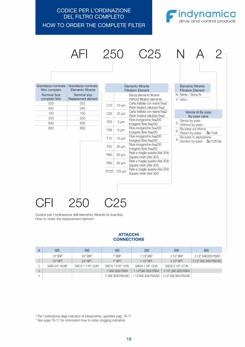
CODICE PER L’ORDINAZIONEDEL FILTRO COMPLETO
HOW TO ORDER THE COMPLETE FILTER
AFI 250 C25 N A 2
CFI 250 C25
Grandezza nominalefiltro completoNominal Sizecomplete filter
Grandezza nominaleElemento filtrante
Nominal sizeReplacement element
025 025040 040100 100250 250630 630850 850
1/2" BSP 3/4” BSP 1" BSP 1 1/2" BSP 2 1/2" BSP 3 1/2" SAE3000 PSI/M
1/2" NPT 3/4” NPT 1" NPT 1 1/2" NPT 2 1/2" NPT 3 1/2" SAE 3000 PSI/UNC
SAE8-3/4"-16UNF SAE12-1 1/16"-12UN SAE16-1 5/16"-12UN SAE24-1 7/8"-12UN SAE32-2 1/2"-12 UN
1" SAE 3000 PSI/M 1 1/2"SAE 3000 PSI/M 2 1/2" SAE 3000 PSI/M
1" SAE 3000 PSI/UNC 1 1/2"SAE 3000 PSI/UNC 2 1/2" SAE 3000 PSI/UNC
-
1
2
3
4
Elemento filtranteFiltration Element
A 025 040 100 250 630 850
-
C10
C25
F03
F06
F10
F25
R60
R90
R125
10 μm
25 μm
3 μm
6 μm
10 μm
25 μm
60 μm
90 μm
125 μm
Senza elemento filtranteWithout filtration elementsCarta trattata con resine ßx≥2Resin treated cellulose ßx≥2Carta trattata con resine ßx≥2Resin treated cellulose ßx≥2Fibre inorganiche ßx≥200Inorganic fibre ßx≥200Fibre inorganiche ßx≥200Inorganic fibre ßx≥200Fibre inorganiche ßx≥200Inorganic fibre ßx≥200Fibre inorganiche ßx≥200Inorganic fibre ßx≥200Rete a maglia quadra (Aisi 304)Square mesh (Aisi 304)Rete a maglia quadra (Aisi 304)Square mesh (Aisi 304)Rete a maglia quadra (Aisi 304)Square mesh (Aisi 304)
Elemento filtranteFiltration Element
NV
Nitrile / Buna-NViton
Valvola di By-passBy-pass valve
S
R
A
Senza by-passWithout by-passBy-pass sul ritornoReturn by-passBy-pass in aspirazioneSuction by-pass
Δp 3 bar
Δp 0,25 bar
Codice per l'ordinazione dell’elemento filtrante di ricambioHow to order the replacement element
* Per l’ordinazione degli indicatori di intasamento, guardare pag. 16-17* See page 16-17 for information how to order clogging indicators
ATTACCHICONNECTIONS
Omt_AFI:Omt_AFI 17-02-2009 8:05 Pagina 20

19
TABELLE DI CORRISPONDENZACODICI VECCHI-CODICI NUOVI
REFERENCE TABLESOLD PART NUMBER-NEW PART NUMBER
ELEMENTO FILTRANTEFILTRATION ELEMENTS
FILTRO COMPLETOCOMPLETE FILTER
Esempio / Exemple
Codici vecchiOld codes
Codici nuoviNew codes
CFI025ACFI025BCFI025CCFI025UCFI025ECFI025GCFI025H
CFI025C10CFI025C25CFI025R60CFI025R90
CFI025R125CFI025F10CFI025F25
Codici vecchiOld codes
Codici nuoviNew codes
CFI040ACFI040BCFI040CCFI040UCFI040ECFI040GCFI040H
CFI040C10CFI040C25CFI040R60CFI040R90
CFI040R125CFI040F10CFI040F25
Codici vecchiOld codes
Codici nuoviNew codes
CFI100ACFI100BCFI100CCFI100UCFI100ECFI100GCFI100H
CFI100C10CFI100C25CFI100R60CFI100R90
CFI100R125CFI100F10CFI100F25
CFI250ACFI250BCFI250CCFI250UCFI250ECFI250GCFI250H
CFI250C10CFI250C25CFI250R60CFI250R90
CFI250R125CFI250F10CFI250F25
Codici vecchiOld codes
Codici nuoviNew codes
AFI_ _ _A_ _AFI_ _ _B_ _AFI_ _ _C_ _AFI_ _ _U_ _AFI_ _ _E_ _AFI_ _ _G_ _AFI_ _ _H_ _
AFI_ _ _C10_ _AFI_ _ _C25_ _AFI_ _ _R60_ _AFI_ _ _R90_ _
AFI_ _ _R125_ _AFI_ _ _F10_ _AFI_ _ _F25_ _
Codici vecchiOld codes
Codici nuoviNew codes
AFI100CNR AFI100R60NR
CFI630ACFI630BCFI630CCFI630UCFI630ECFI630GCFI630H
CFI630C10CFI630C25CFI630R60CFI630R90
CFI630R125CFI630F10CFI630F25
CFI850ACFI850BCFI850CCFI850UCFI850ECFI850GCFI850H
CFI850C10CFI850C25CFI850R60CFI850R90
CFI850R125CFI850F10CFI850F25
Codici nuoviNew codes
Codici vecchiOld codes
Codici nuoviNew codes
Codici vecchiOld codes
Codici nuoviNew codes
Codici vecchiOld codes
Omt_AFI:Omt_AFI 17-02-2009 8:05 Pagina 21