Download - zenon driver manual - BrTcp32 - Copa-Data
zenon driver manual BrTcp32
v.7.60

©2017 Ing. Punzenberger COPA-DATA GmbH
All rights reserved.
Distribution and/or reproduction of this document or parts thereof in any form are permitted solely with the written permission of the company COPA-DATA. Technical data is only used for product description and are not guaranteed qualities in the legal sense. Subject to change, technical or otherwise.
3
Contents
1. Welcome to COPA-DATA help ...................................................................................................... 5
2. BrTcp32 ....................................................................................................................................... 6
3. BRTCP32 - Data sheet .................................................................................................................. 6
4. Driver history .............................................................................................................................. 7
5. Requirements .............................................................................................................................. 8
5.1 PC ................................................................................................................................................................ 8
5.2 Control ........................................................................................................................................................ 9
6. Configuration .............................................................................................................................. 9
6.1 Creating a driver ........................................................................................................................................ 10
6.2 Settings in the driver dialog ...................................................................................................................... 13
6.2.1 General ....................................................................................................................................... 14
6.2.2 Basic setting ................................................................................................................................ 17
6.2.3 Conn. TCP/IP ............................................................................................................................... 18
7. Creating variables ...................................................................................................................... 19
7.1 Creating variables in the Editor ................................................................................................................. 19
7.2 Addressing ................................................................................................................................................. 23
7.3 Driver objects and datatypes .................................................................................................................... 23
7.3.1 Driver objects ............................................................................................................................. 24
7.3.2 Mapping of the data types ......................................................................................................... 26
7.4 Creating variables by importing ................................................................................................................ 26
7.4.1 XML import ................................................................................................................................. 26
7.4.2 DBF Import/Export ..................................................................................................................... 27
7.4.3 Online import ............................................................................................................................. 33
7.5 Communication details (Driver variables) ................................................................................................. 33
8. Driver-specific functions ............................................................................................................ 39
9. Driver commands ...................................................................................................................... 40

4
10. Error analysis ............................................................................................................................. 41
10.1 Analysis tool .............................................................................................................................................. 41
10.2 Error numbers ........................................................................................................................................... 43
10.3 Check list ................................................................................................................................................... 51
Welcome to COPA-DATA help
5
1. Welcome to COPA-DATA help
ZENON VIDEO-TUTORIALS
You can find practical examples for project configuration with zenon in our YouTube channel
(https://www.copadata.com/tutorial_menu). The tutorials are grouped according to topics and
give an initial insight into working with different zenon modules. All tutorials are available in
English.
GENERAL HELP
If you cannot find any information you require in this help chapter or can think of anything that you would like added, please send an email to [email protected] (mailto:[email protected]).
PROJECT SUPPORT
You can receive support for any real project you may have from our Support Team, who you can contact via email at [email protected] (mailto:[email protected]).
LICENSES AND MODULES
If you find that you need other modules or licenses, our staff will be happy to help you. Email [email protected] (mailto:[email protected]).
BrTcp32
6
2. BrTcp32
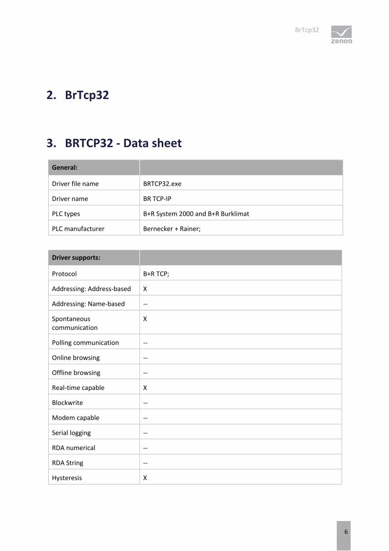
3. BRTCP32 - Data sheet
General:
Driver file name BRTCP32.exe
Driver name BR TCP-IP
PLC types B+R System 2000 and B+R Burklimat
PLC manufacturer Bernecker + Rainer;
Driver supports:
Protocol B+R TCP;
Addressing: Address-based X
Addressing: Name-based --
Spontaneous communication
X
Polling communication --
Online browsing --
Offline browsing --
Real-time capable X
Blockwrite --
Modem capable --
Serial logging --
RDA numerical --
RDA String --
Hysteresis X
Driver history
7
extended API --
Supports status bit WR-SUC X
alternative IP address --
Requirements:
Hardware PC Standard network card
Software PC --
Hardware PLC --
Software PLC Needs special software in the B+R System 2000 PLC
Requires v-dll --
Platforms:
Operating systems Windows 7, 8, 8.1, 10, Server 2008R2, Server 2012, Server 2012R2, Server 2016;
CE platforms -;
4. Driver history
Date Driver version Change
07.07.08 1800 Created driver documentation
DRIVER VERSIONING
The versioning of the drivers was changed with zenon 7.10. There is a cross-version build number as of this version. This is the number in the 4th position of the file version, For example: 7.10.0.4228 means: The driver is for version 7.10 service pack 0, and has the build number 4228.
Requirements
8
Expansions or error rectifications will be incorporated into a build in the future and are then available from the next consecutive build number.
Example
A driver extension was implemented in build 4228. The driver that you are using is build number 8322. Because the build number of your driver is higher than the build number of the extension, the extension is included. The version number of the driver (the first three digits of the file version) do not have any significance in relation to this. The drivers are version-agnostic
5. Requirements
This chapter contains information on the requirements that are necessary for use of this driver.
5.1 PC
HARDWARE
Network card
Interface: Ethernet
Protocol: B&R TCP
SOFTWARE
Copy the driver file BrTcp32.exe into the current program directory (unless it is already there) and enter it into the TREIBER_EN.XML file with the tool DriverInfo.exe.
The configuration file (according to the driver settings) must be sent to the project directory on the target PC. For this, the file has to be entered in the Remote Transport explicitly.
Configuration
9
5.2 Control
HARDWARE
B&R System 2000
Interface: Ethernet
Protocol: B&R TCP
Ethernet connection (TCP/IP). The handling function block must be installed and configured on the PLC.
6. Configuration
In this chapter you will learn how to use the driver in a project and which settings you can change.
Information
Find out more about further settings for zenon variables in the chapter Variables (main.chm::/15247.htm) of the online manual.
Configuration
10
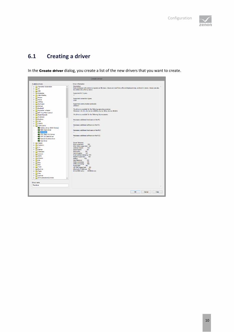
6.1 Creating a driver
In the Create driver dialog, you create a list of the new drivers that you want to create.
Configuration
11
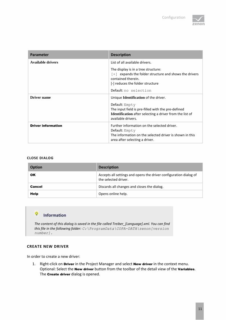
Parameter Description
Available drivers List of all available drivers.
The display is in a tree structure: [+] expands the folder structure and shows the drivers contained therein. [-] reduces the folder structure
Default: no selection
Driver name Unique Identification of the driver.
Default: Empty The input field is pre-filled with the pre-defined Identification after selecting a driver from the list of available drivers.
Driver information Further information on the selected driver. Default: Empty The information on the selected driver is shown in this area after selecting a driver.
CLOSE DIALOG
Option Description
OK Accepts all settings and opens the driver configuration dialog of the selected driver.
Cancel Discards all changes and closes the dialog.
Help Opens online help.
Information
The content of this dialog is saved in the file called Treiber_[Language].xml. You can find
this file in the following folder: C:\ProgramData\COPA-DATA\zenon[version number].
CREATE NEW DRIVER
In order to create a new driver:
1. Right-click on Driver in the Project Manager and select New driver in the context menu. Optional: Select the New driver button from the toolbar of the detail view of the Variables. The Create driver dialog is opened.
Configuration
12
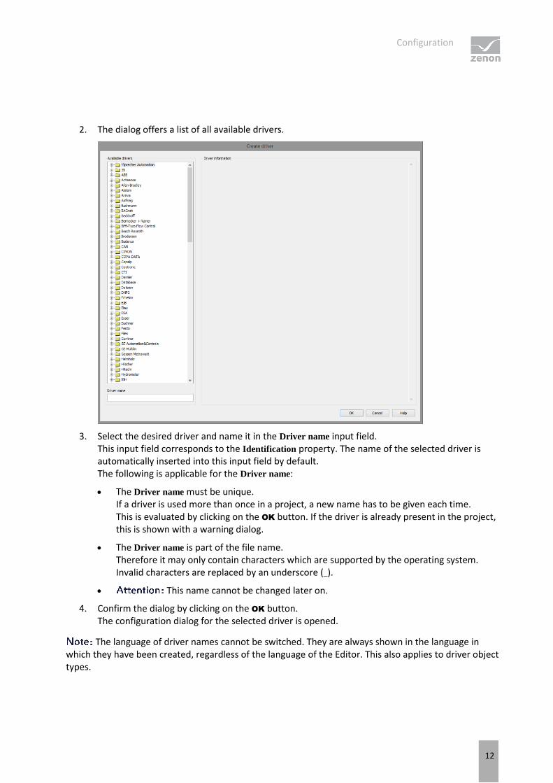
2. The dialog offers a list of all available drivers.
3. Select the desired driver and name it in the Driver name input field. This input field corresponds to the Identification property. The name of the selected driver is automatically inserted into this input field by default. The following is applicable for the Driver name:
The Driver name must be unique. If a driver is used more than once in a project, a new name has to be given each time. This is evaluated by clicking on the OK button. If the driver is already present in the project, this is shown with a warning dialog.
The Driver name is part of the file name. Therefore it may only contain characters which are supported by the operating system. Invalid characters are replaced by an underscore (_).
This name cannot be changed later on.
4. Confirm the dialog by clicking on the OK button. The configuration dialog for the selected driver is opened.
The language of driver names cannot be switched. They are always shown in the language in which they have been created, regardless of the language of the Editor. This also applies to driver object types.
Configuration
13
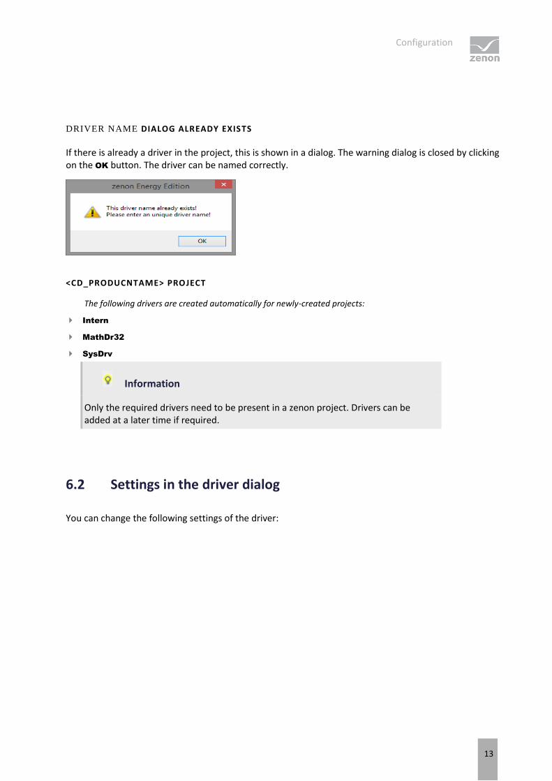
DRIVER NAME DIALOG ALREADY EXISTS
If there is already a driver in the project, this is shown in a dialog. The warning dialog is closed by clicking on the OK button. The driver can be named correctly.
<CD_PRODUCNTAME> PROJECT
The following drivers are created automatically for newly-created projects:
Intern
MathDr32
SysDrv
Information
Only the required drivers need to be present in a zenon project. Drivers can be added at a later time if required.
6.2 Settings in the driver dialog
You can change the following settings of the driver:
Configuration
14
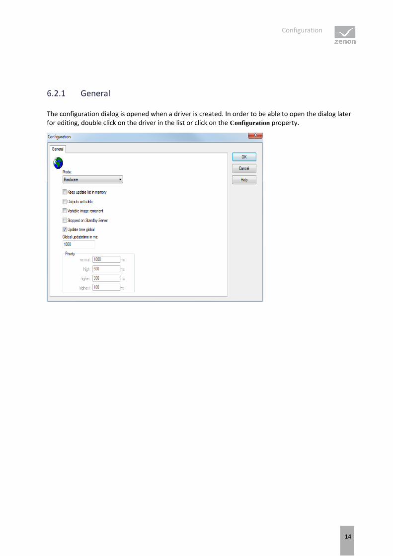
6.2.1 General
The configuration dialog is opened when a driver is created. In order to be able to open the dialog later for editing, double click on the driver in the list or click on the Configuration property.
Configuration
15
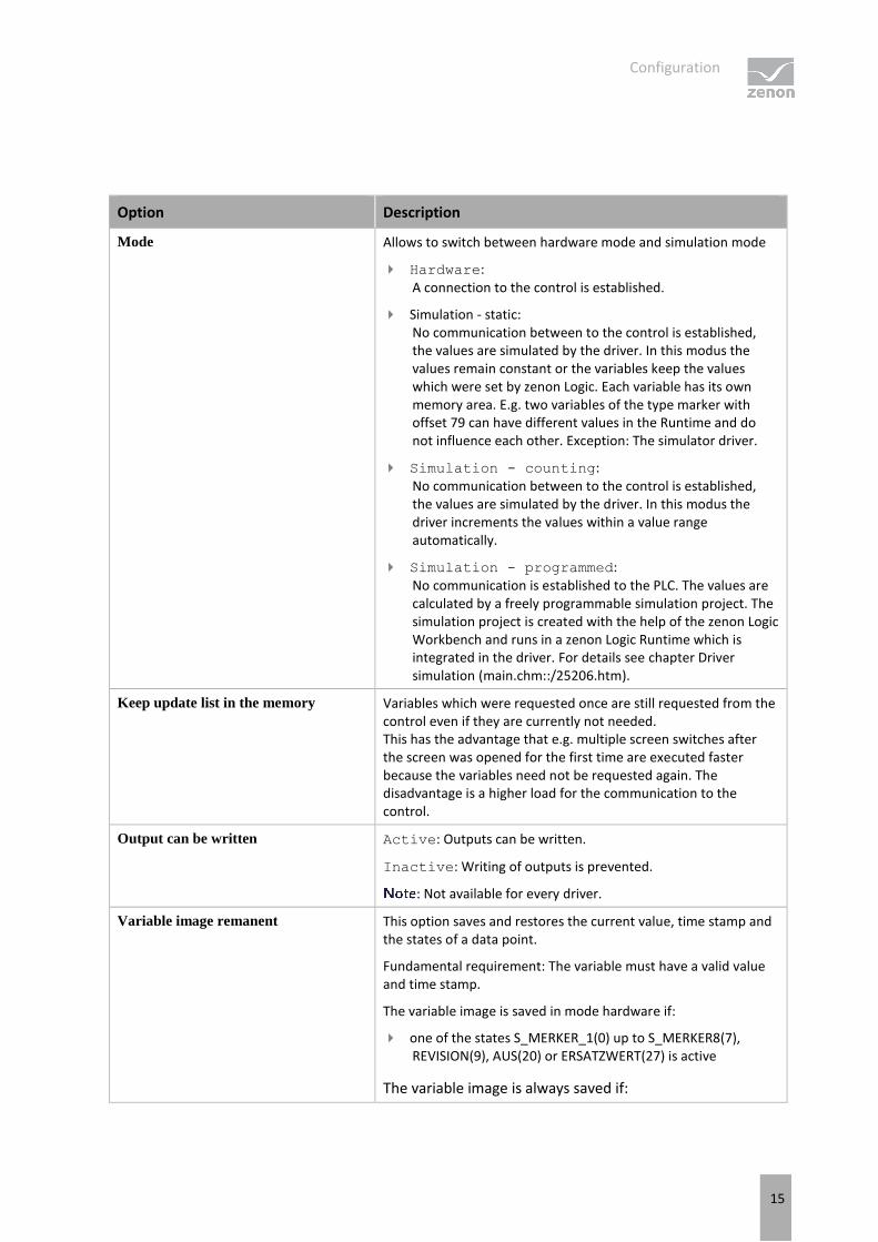
Option Description
Mode Allows to switch between hardware mode and simulation mode
Hardware: A connection to the control is established.
Simulation - static: No communication between to the control is established, the values are simulated by the driver. In this modus the values remain constant or the variables keep the values which were set by zenon Logic. Each variable has its own memory area. E.g. two variables of the type marker with offset 79 can have different values in the Runtime and do not influence each other. Exception: The simulator driver.
Simulation - counting: No communication between to the control is established, the values are simulated by the driver. In this modus the driver increments the values within a value range automatically.
Simulation - programmed: No communication is established to the PLC. The values are calculated by a freely programmable simulation project. The simulation project is created with the help of the zenon Logic Workbench and runs in a zenon Logic Runtime which is integrated in the driver. For details see chapter Driver simulation (main.chm::/25206.htm).
Keep update list in the memory Variables which were requested once are still requested from the control even if they are currently not needed. This has the advantage that e.g. multiple screen switches after the screen was opened for the first time are executed faster because the variables need not be requested again. The disadvantage is a higher load for the communication to the control.
Output can be written Active: Outputs can be written.
Inactive: Writing of outputs is prevented.
: Not available for every driver.
Variable image remanent This option saves and restores the current value, time stamp and the states of a data point.
Fundamental requirement: The variable must have a valid value and time stamp.
The variable image is saved in mode hardware if:
one of the states S_MERKER_1(0) up to S_MERKER8(7), REVISION(9), AUS(20) or ERSATZWERT(27) is active
The variable image is always saved if:
Configuration
16
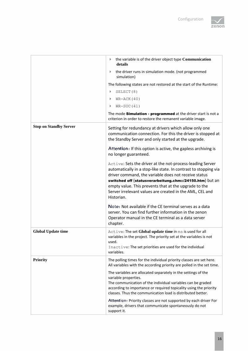
the variable is of the driver object type Communication
details
the driver runs in simulation mode. (not programmed simulation)
The following states are not restored at the start of the Runtime:
SELECT(8)
WR-ACK(40)
WR-SUC(41)
The mode Simulation - programmed at the driver start is not a criterion in order to restore the remanent variable image.
Stop on Standby Server Setting for redundancy at drivers which allow only one communication connection. For this the driver is stopped at the Standby Server and only started at the upgrade.
If this option is active, the gapless archiving is no longer guaranteed.
Active: Sets the driver at the not-process-leading Server automatically in a stop-like state. In contrast to stopping via driver command, the variable does not receive status switched off (statusverarbeitung.chm::/24150.htm) but an empty value. This prevents that at the upgrade to the Server irrelevant values are created in the AML, CEL and Historian.
Not available if the CE terminal serves as a data server. You can find further information in the zenon Operator manual in the CE terminal as a data server chapter.
Global Update time Active: The set Global update time in ms is used for all variables in the project. The priority set at the variables is not used. Inactive: The set priorities are used for the individual variables.
Priority The polling times for the individual priority classes are set here. All variables with the according priority are polled in the set time.
The variables are allocated separately in the settings of the variable properties. The communication of the individual variables can be graded according to importance or required topicality using the priority classes. Thus the communication load is distributed better.
Priority classes are not supported by each driver For example, drivers that communicate spontaneously do not support it.
Configuration
17
CLOSE DIALOG
Options Description
OK Applies all changes in all tabs and closes the dialog.
Cancel Discards all changes in all tabs and closes the dialog.
Help Opens online help.
UPDATE TIME FOR CYCLICAL DRIVERS
The following applies for cyclical drivers:
For Set value, advising of variables and Requests, a read cycle is immediately triggered for all drivers - regardless of the set update time. This ensures that the value is immediately available for visualization after writing. Update times can therefore be shorter than pre-set for cyclical drivers.
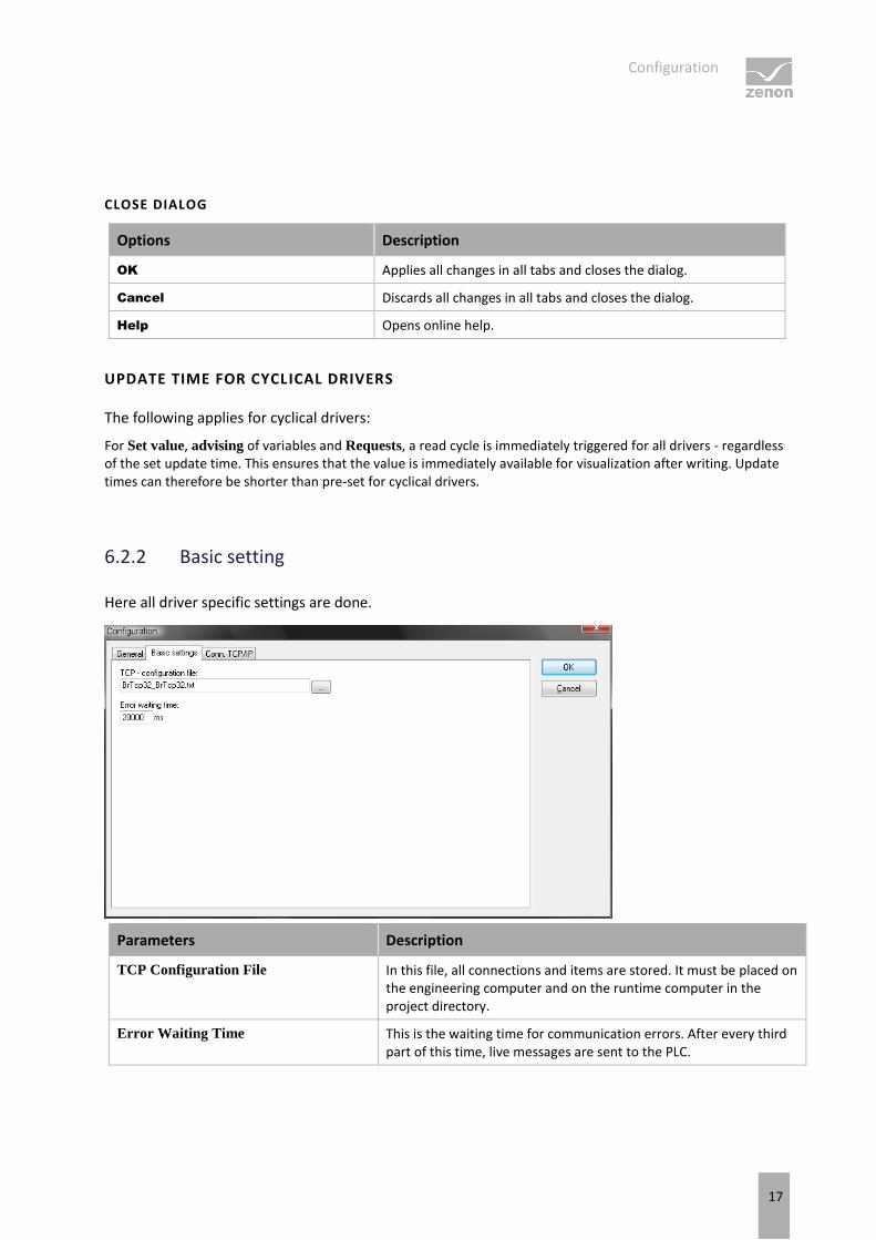
6.2.2 Basic setting
Here all driver specific settings are done.
Parameters Description
TCP Configuration File In this file, all connections and items are stored. It must be placed on the engineering computer and on the runtime computer in the project directory.
Error Waiting Time This is the waiting time for communication errors. After every third part of this time, live messages are sent to the PLC.
Configuration
18
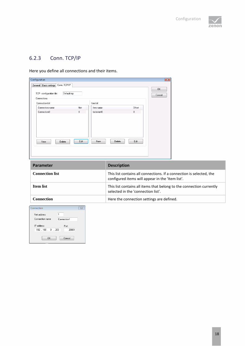
6.2.3 Conn. TCP/IP
Here you define all connections and their items.
Parameter Description
Connection list This list contains all connections. If a connection is selected, the configured items will appear in the 'Item list'.
Item list This list contains all items that belong to the connection currently selected in the 'connection list'.
Connection Here the connection settings are defined.
Creating variables
19
Parameter Description
Net address Enter a unique net address that will be used to associate a variable in zenon with this connection.
Connection name Freely definable name.
IP address IP address of PLC.
Port TCP port on the PLC which the server is listening to.
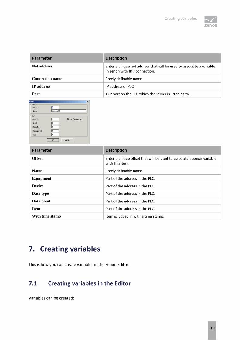
Parameter Description
Offset Enter a unique offset that will be used to associate a zenon variable with this item.
Name Freely definable name.
Equipment Part of the address in the PLC.
Device Part of the address in the PLC.
Data type Part of the address in the PLC.
Data point Part of the address in the PLC.
Item Part of the address in the PLC.
With time stamp Item is logged in with a time stamp.
7. Creating variables
This is how you can create variables in the zenon Editor:
7.1 Creating variables in the Editor
Variables can be created:
Creating variables
20
as simple variables
in arrays (main.chm::/15262.htm)
as structure variables (main.chm::/15278.htm)
VARIABLE DIALOG
To create a new variable, regardless of which type:
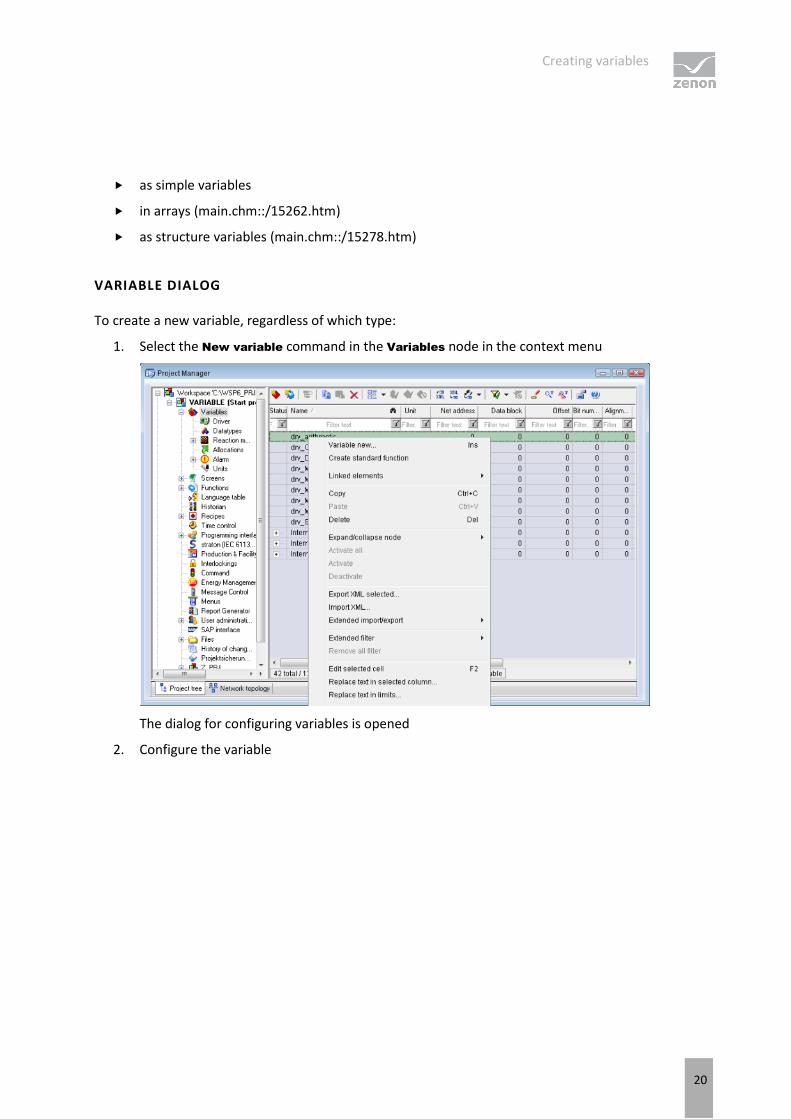
1. Select the New variable command in the Variables node in the context menu
The dialog for configuring variables is opened
2. Configure the variable
Creating variables
21
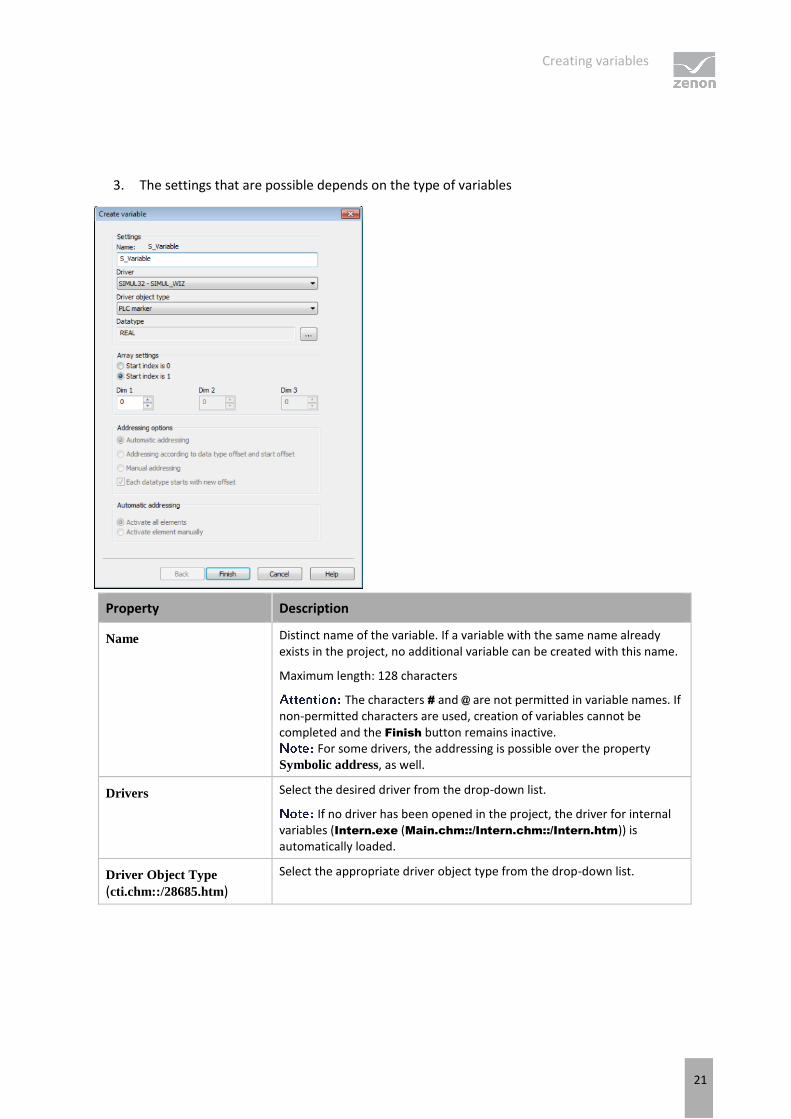
3. The settings that are possible depends on the type of variables
Property Description
Name Distinct name of the variable. If a variable with the same name already exists in the project, no additional variable can be created with this name.
Maximum length: 128 characters
The characters # and @ are not permitted in variable names. If non-permitted characters are used, creation of variables cannot be completed and the Finish button remains inactive.
For some drivers, the addressing is possible over the property Symbolic address, as well.
Drivers Select the desired driver from the drop-down list.
If no driver has been opened in the project, the driver for internal variables (Intern.exe (Main.chm::/Intern.chm::/Intern.htm)) is automatically loaded.
Driver Object Type (cti.chm::/28685.htm)
Select the appropriate driver object type from the drop-down list.
Creating variables
22
Data Type Select the desired data type. Click on the ... button to open the selection dialog.
Array settings Expanded settings for array variables. You can find details in the Arrays chapter.
Addressing options Expanded settings for arrays and structure variables. You can find details in the respective section.
Automatic element
activation Expanded settings for arrays and structure variables. You can find details in the respective section.
SYMBOLIC ADDRESS
The Symbolic address property can be used for addressing as an alternative to the Name or Identification of the variables. Selection is made in the driver dialog; configuration is carried out in the variable property. When importing variables of supported drivers, the property is entered automatically.
Maximum length: 1024 characters.
INHERITANCE FROM DATA TYPE
Measuring range, Signal range and Set value are always:
derived from the datatype
Automatically adapted if the data type is changed
If a change is made to a data type that does not support the set signal range, the signal
range is amended automatically. For example, for a change from INT to SINT, the signal range is changed to 127. The amendment is also carried out if the signal range was not inherited from the data type. In this case, the measuring range must be adapted manually.
Creating variables
23
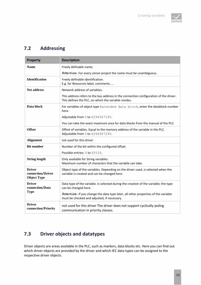
7.2 Addressing
Property Description
Name Freely definable name.
For every zenon project the name must be unambiguous.
Identification Freely definable identification. E.g. for Resources label, comments, ...
Net address Network address of variables.
This address refers to the bus address in the connection configuration of the driver. This defines the PLC, on which the variable resides.
Data block For variables of object type Extended data block, enter the datablock number
here.
Adjustable from 0 to 4294967295.
You can take the exact maximum area for data blocks from the manual of the PLC.
Offset Offset of variables. Equal to the memory address of the variable in the PLC. Adjustable from 0 to 4294967295.
Alignment not used for this driver
Bit number Number of the bit within the configured offset.
Possible entries: 0 to 65535.
String length Only available for String variables. Maximum number of characters that the variable can take.
Driver
connection/Driver
Object Type
Object type of the variables. Depending on the driver used, is selected when the variable is created and can be changed here.
Driver
connection/Data
Type
Data type of the variable. Is selected during the creation of the variable; the type can be changed here.
If you change the data type later, all other properties of the variable must be checked and adjusted, if necessary.
Driver
connection/Priority not used for this driver The driver does not support cyclically-poling communication in priority classes.
7.3 Driver objects and datatypes
Driver objects are areas available in the PLC, such as markers, data blocks etc. Here you can find out which driver objects are provided by the driver and which IEC data types can be assigned to the respective driver objects.

Creating variables
24
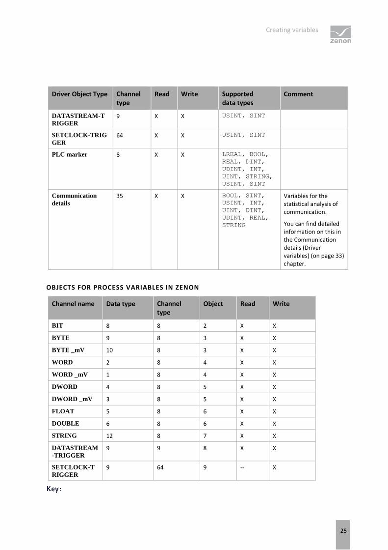
7.3.1 Driver objects
The following driver object types are available in this driver:
Creating variables
25
Driver Object Type Channel type
Read Write Supported data types
Comment
DATASTREAM-T
RIGGER 9 X X USINT, SINT
SETCLOCK-TRIG
GER 64 X X USINT, SINT
PLC marker 8 X X LREAL, BOOL,
REAL, DINT,
UDINT, INT,
UINT, STRING,
USINT, SINT
Communication
details 35 X X BOOL, SINT,
USINT, INT,
UINT, DINT,
UDINT, REAL,
STRING
Variables for the statistical analysis of communication.
You can find detailed information on this in the Communication details (Driver variables) (on page 33) chapter.
OBJECTS FOR PROCESS VARIABLES IN ZENON
Channel name Data type Channel type
Object Read Write
BIT 8 8 2 X X
BYTE 9 8 3 X X
BYTE _mV 10 8 3 X X
WORD 2 8 4 X X
WORD _mV 1 8 4 X X
DWORD 4 8 5 X X
DWORD _mV 3 8 5 X X
FLOAT 5 8 6 X X
DOUBLE 6 8 6 X X
STRING 12 8 7 X X
DATASTREAM
-TRIGGER 9 9 8 X X
SETCLOCK-T
RIGGER 9 64 9 -- X
Creating variables
26
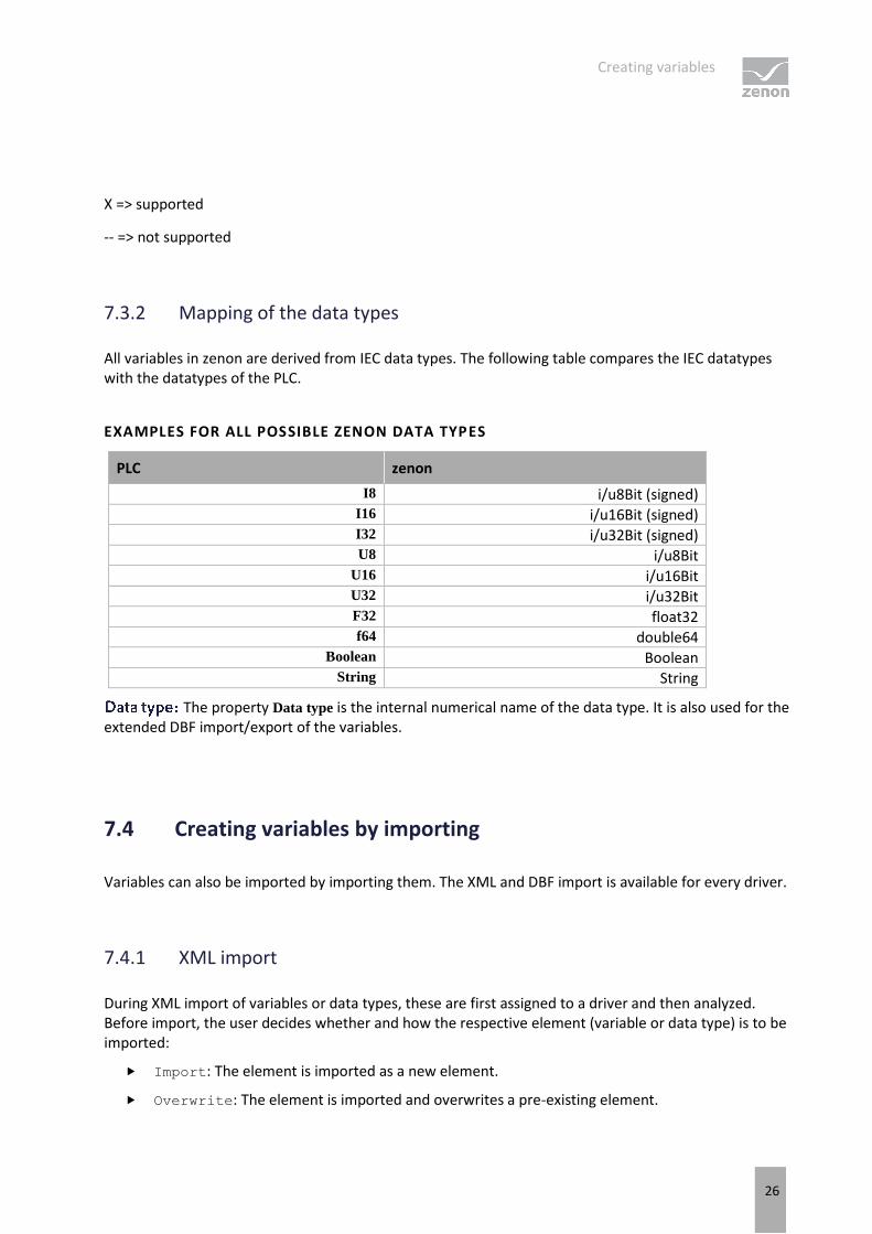
X => supported
-- => not supported
7.3.2 Mapping of the data types
All variables in zenon are derived from IEC data types. The following table compares the IEC datatypes with the datatypes of the PLC.
EXAMPLES FOR ALL POSSIBLE ZENON DATA TYPES
PLC zenon
I8 i/u8Bit (signed) I16 i/u16Bit (signed) I32 i/u32Bit (signed) U8 i/u8Bit
U16 i/u16Bit U32 i/u32Bit F32 float32 f64 double64
Boolean Boolean String String
The property Data type is the internal numerical name of the data type. It is also used for the extended DBF import/export of the variables.
7.4 Creating variables by importing
Variables can also be imported by importing them. The XML and DBF import is available for every driver.
7.4.1 XML import
During XML import of variables or data types, these are first assigned to a driver and then analyzed. Before import, the user decides whether and how the respective element (variable or data type) is to be imported:
Import: The element is imported as a new element.
Overwrite: The element is imported and overwrites a pre-existing element.
Creating variables
27
Do not import: The element is not imported.
The actions and their durations are shown in a progress bar during import.
REQUIREMENTS
The following conditions are applicable during import:
Backward compatibility
At the XML import/export there is no backward compatibility. Data from older zenon versions cannot be taken over. The handover of data from newer to older versions is not supported.
Consistency
The XML file to be imported has to be consistent. There is no plausibility check on importing the file. If there are errors in the import file, this can lead to undesirable effects in the project.
Particular attention must be paid to this, primarily if not all properties exist in the XML file and these are then filled with default values. E.g.: A binary variable has a limit value of 300.
Structure data types
Structure data types must have the same number of structure elements. Example: A structure data type in the project has 3 structure elements. A data type with the same name in the XML file has 4 structure elements. Then none of the variables based on this data type in the export file are imported into the project.
Hint
You can find further information on XML import in the Import - Export manual, in the XML import (main.chm::/13046.htm) chapter.
7.4.2 DBF Import/Export
Data can be exported to and imported from dBase.
Information
Import and Export via CSV or dBase supported; no driver specific variable settings, such as formulas. Use export/import via XML for this.
Creating variables
28
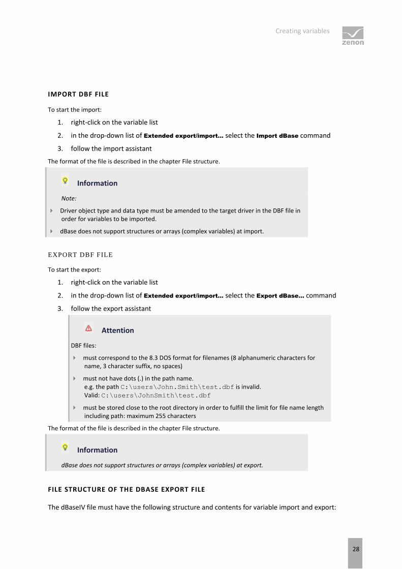
IMPORT DBF FILE
To start the import:
1. right-click on the variable list
2. in the drop-down list of Extended export/import... select the Import dBase command
3. follow the import assistant
The format of the file is described in the chapter File structure.
Information
Note:
Driver object type and data type must be amended to the target driver in the DBF file in order for variables to be imported.
dBase does not support structures or arrays (complex variables) at import.
EXPORT DBF FILE
To start the export:
1. right-click on the variable list
2. in the drop-down list of Extended export/import... select the Export dBase... command
3. follow the export assistant
Attention
DBF files:
must correspond to the 8.3 DOS format for filenames (8 alphanumeric characters for name, 3 character suffix, no spaces)
must not have dots (.) in the path name. e.g. the path C:\users\John.Smith\test.dbf is invalid.
Valid: C:\users\JohnSmith\test.dbf
must be stored close to the root directory in order to fulfill the limit for file name length including path: maximum 255 characters
The format of the file is described in the chapter File structure.
Information
dBase does not support structures or arrays (complex variables) at export.
FILE STRUCTURE OF THE DBASE EXPORT FILE
The dBaseIV file must have the following structure and contents for variable import and export:
Creating variables
29
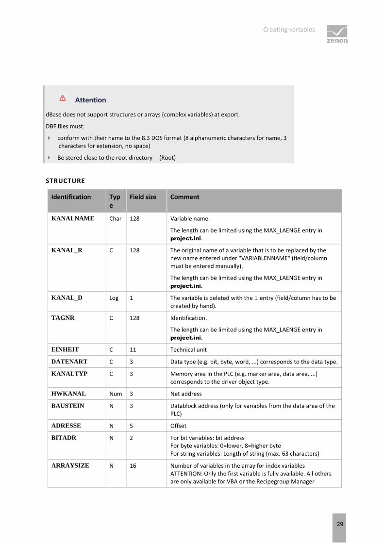
Attention
dBase does not support structures or arrays (complex variables) at export.
DBF files must:
conform with their name to the 8.3 DOS format (8 alphanumeric characters for name, 3 characters for extension, no space)
Be stored close to the root directory (Root)
STRUCTURE
Identification Type
Field size Comment
KANALNAME Char 128 Variable name.
The length can be limited using the MAX_LAENGE entry in project.ini.
KANAL_R C 128 The original name of a variable that is to be replaced by the new name entered under "VARIABLENNAME" (field/column must be entered manually).
The length can be limited using the MAX_LAENGE entry in project.ini.
KANAL_D Log 1 The variable is deleted with the 1 entry (field/column has to be created by hand).
TAGNR C 128 Identification.
The length can be limited using the MAX_LAENGE entry in project.ini.
EINHEIT C 11 Technical unit
DATENART C 3 Data type (e.g. bit, byte, word, ...) corresponds to the data type.
KANALTYP C 3 Memory area in the PLC (e.g. marker area, data area, ...) corresponds to the driver object type.
HWKANAL Num 3 Net address
BAUSTEIN N 3 Datablock address (only for variables from the data area of the PLC)
ADRESSE N 5 Offset
BITADR N 2 For bit variables: bit address For byte variables: 0=lower, 8=higher byte For string variables: Length of string (max. 63 characters)
ARRAYSIZE N 16 Number of variables in the array for index variables ATTENTION: Only the first variable is fully available. All others are only available for VBA or the Recipegroup Manager
Creating variables
30
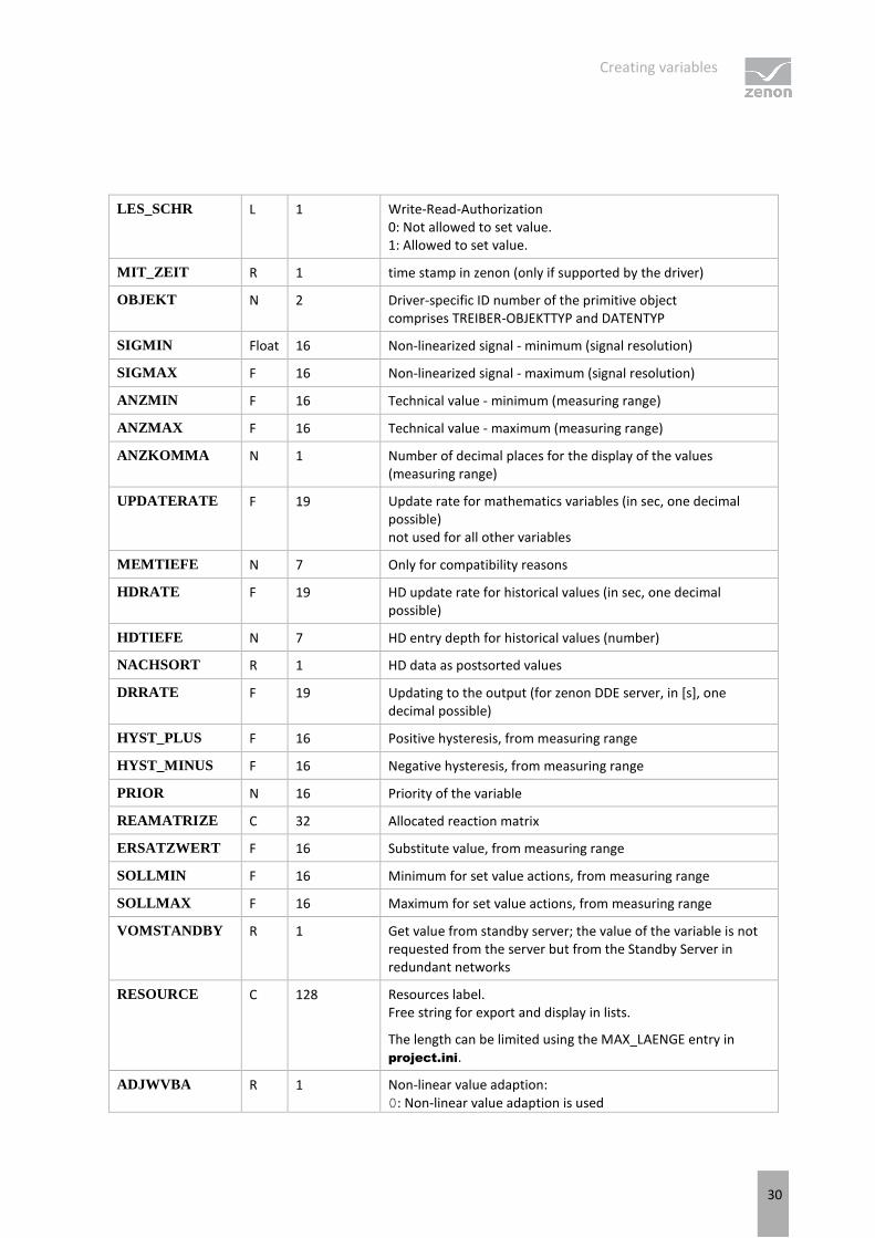
LES_SCHR L 1 Write-Read-Authorization 0: Not allowed to set value. 1: Allowed to set value.
MIT_ZEIT R 1 time stamp in zenon (only if supported by the driver)
OBJEKT N 2 Driver-specific ID number of the primitive object comprises TREIBER-OBJEKTTYP and DATENTYP
SIGMIN Float 16 Non-linearized signal - minimum (signal resolution)
SIGMAX F 16 Non-linearized signal - maximum (signal resolution)
ANZMIN F 16 Technical value - minimum (measuring range)
ANZMAX F 16 Technical value - maximum (measuring range)
ANZKOMMA N 1 Number of decimal places for the display of the values (measuring range)
UPDATERATE F 19 Update rate for mathematics variables (in sec, one decimal possible) not used for all other variables
MEMTIEFE N 7 Only for compatibility reasons
HDRATE F 19 HD update rate for historical values (in sec, one decimal possible)
HDTIEFE N 7 HD entry depth for historical values (number)
NACHSORT R 1 HD data as postsorted values
DRRATE F 19 Updating to the output (for zenon DDE server, in [s], one decimal possible)
HYST_PLUS F 16 Positive hysteresis, from measuring range
HYST_MINUS F 16 Negative hysteresis, from measuring range
PRIOR N 16 Priority of the variable
REAMATRIZE C 32 Allocated reaction matrix
ERSATZWERT F 16 Substitute value, from measuring range
SOLLMIN F 16 Minimum for set value actions, from measuring range
SOLLMAX F 16 Maximum for set value actions, from measuring range
VOMSTANDBY R 1 Get value from standby server; the value of the variable is not requested from the server but from the Standby Server in redundant networks
RESOURCE C 128 Resources label. Free string for export and display in lists.
The length can be limited using the MAX_LAENGE entry in project.ini.
ADJWVBA R 1 Non-linear value adaption: 0: Non-linear value adaption is used
Creating variables
31
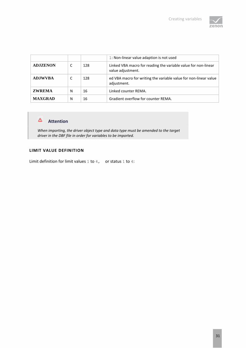
1: Non-linear value adaption is not used
ADJZENON C 128 Linked VBA macro for reading the variable value for non-linear value adjustment.
ADJWVBA C 128 ed VBA macro for writing the variable value for non-linear value adjustment.
ZWREMA N 16 Linked counter REMA.
MAXGRAD N 16 Gradient overflow for counter REMA.
Attention
When importing, the driver object type and data type must be amended to the target driver in the DBF file in order for variables to be imported.
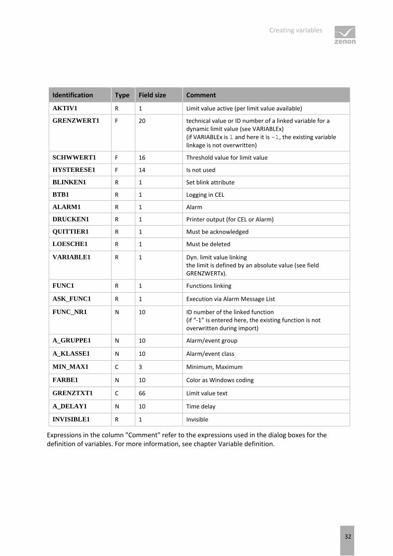
LIMIT VALUE DEFINITION
Limit definition for limit values 1 to 4, or status 1 to 4:
Creating variables
32
Identification Type Field size Comment
AKTIV1 R 1 Limit value active (per limit value available)
GRENZWERT1 F 20 technical value or ID number of a linked variable for a dynamic limit value (see VARIABLEx) (if VARIABLEx is 1 and here it is -1, the existing variable linkage is not overwritten)
SCHWWERT1 F 16 Threshold value for limit value
HYSTERESE1 F 14 Is not used
BLINKEN1 R 1 Set blink attribute
BTB1 R 1 Logging in CEL
ALARM1 R 1 Alarm
DRUCKEN1 R 1 Printer output (for CEL or Alarm)
QUITTIER1 R 1 Must be acknowledged
LOESCHE1 R 1 Must be deleted
VARIABLE1 R 1 Dyn. limit value linking the limit is defined by an absolute value (see field GRENZWERTx).
FUNC1 R 1 Functions linking
ASK_FUNC1 R 1 Execution via Alarm Message List
FUNC_NR1 N 10 ID number of the linked function (if “-1” is entered here, the existing function is not overwritten during import)
A_GRUPPE1 N 10 Alarm/event group
A_KLASSE1 N 10 Alarm/event class
MIN_MAX1 C 3 Minimum, Maximum
FARBE1 N 10 Color as Windows coding
GRENZTXT1 C 66 Limit value text
A_DELAY1 N 10 Time delay
INVISIBLE1 R 1 Invisible
Expressions in the column "Comment" refer to the expressions used in the dialog boxes for the definition of variables. For more information, see chapter Variable definition.
Creating variables
33
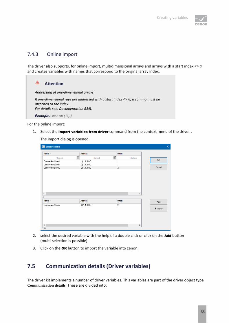
7.4.3 Online import
The driver also supports, for online import, multidimensional arrays and arrays with a start index <> 0 and creates variables with names that correspond to the original array index.
Attention
Addressing of one-dimensional arrays:
If one-dimensional rays are addressed with a start index <> 0, a comma must be attached to the index. For details see: Documentation B&R.
zenon[3,]
For the online import:
1. Select the Import variables from driver command from the context menu of the driver .
The import dialog is opened.
2. select the desired variable with the help of a double click or click on the Add button (multi-selection is possible)
3. Click on the OK button to import the variable into zenon.
7.5 Communication details (Driver variables)
The driver kit implements a number of driver variables. This variables are part of the driver object type Communication details. These are divided into:
Creating variables
34
Information
Configuration
Statistics and
Error message
The definitions of the variables implemented in the driver kit are available in the import file drvvar.dbf
(on the installation medium in the \Predefined\Variables folder) and can be imported from there.
Variable names must be unique in zenon. If driver variables of the driver object type Communication details are to be imported from drvvar.dbf again, the variables that were imported beforehand must be renamed.
Information
Not every driver supports all driver variables of the driver object type Communication
details.
For example:
Variables for modem information are only supported by modem-compatible drivers
Variables for the polling cycle only for pure polling drivers
Connection-related information such as ErrorMSG only for drivers that only edit one connection at a a time
Creating variables
35
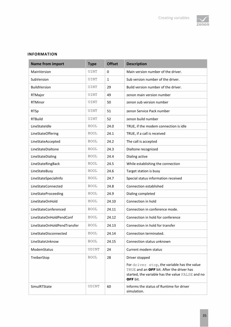
INFORMATION
Name from import Type Offset Description
MainVersion UINT 0 Main version number of the driver.
SubVersion UINT 1 Sub version number of the driver.
BuildVersion UINT 29 Build version number of the driver.
RTMajor UINT 49 zenon main version number
RTMinor UINT 50 zenon sub version number
RTSp UINT 51 zenon Service Pack number
RTBuild UINT 52 zenon build number
LineStateIdle BOOL 24.0 TRUE, if the modem connection is idle
LineStateOffering BOOL 24.1 TRUE, if a call is received
LineStateAccepted BOOL 24.2 The call is accepted
LineStateDialtone BOOL 24.3 Dialtone recognized
LineStateDialing BOOL 24.4 Dialing active
LineStateRingBack BOOL 24.5 While establishing the connection
LineStateBusy BOOL 24.6 Target station is busy
LineStateSpecialInfo BOOL 24.7 Special status information received
LineStateConnected BOOL 24.8 Connection established
LineStateProceeding BOOL 24.9 Dialing completed
LineStateOnHold BOOL 24.10 Connection in hold
LineStateConferenced BOOL 24.11 Connection in conference mode.
LineStateOnHoldPendConf BOOL 24.12 Connection in hold for conference
LineStateOnHoldPendTransfer BOOL 24.13 Connection in hold for transfer
LineStateDisconnected BOOL 24.14 Connection terminated.
LineStateUnknow BOOL 24.15 Connection status unknown
ModemStatus UDINT 24 Current modem status
TreiberStop BOOL 28 Driver stopped
For driver stop, the variable has the value
TRUE and an OFF bit. After the driver has
started, the variable has the value FALSE and no
OFF bit.
SimulRTState UDINT 60 Informs the status of Runtime for driver simulation.
Creating variables
36
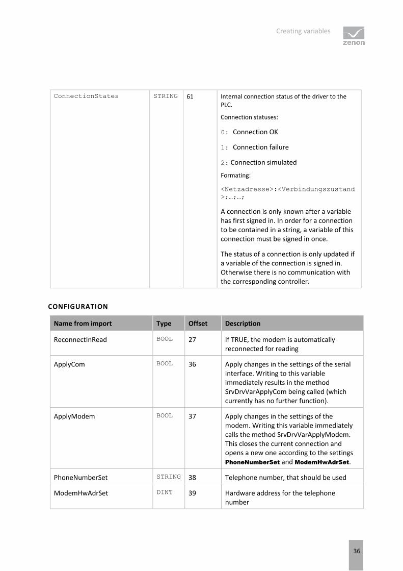
ConnectionStates STRING 61 Internal connection status of the driver to the PLC.
Connection statuses:
0: Connection OK
1: Connection failure
2: Connection simulated
Formating:
<Netzadresse>:<Verbindungszustand
>;…;…;
A connection is only known after a variable has first signed in. In order for a connection to be contained in a string, a variable of this connection must be signed in once.
The status of a connection is only updated if a variable of the connection is signed in. Otherwise there is no communication with the corresponding controller.
CONFIGURATION
Name from import Type Offset Description
ReconnectInRead BOOL 27 If TRUE, the modem is automatically reconnected for reading
ApplyCom BOOL 36 Apply changes in the settings of the serial interface. Writing to this variable immediately results in the method SrvDrvVarApplyCom being called (which currently has no further function).
ApplyModem BOOL 37 Apply changes in the settings of the modem. Writing this variable immediately calls the method SrvDrvVarApplyModem. This closes the current connection and opens a new one according to the settings PhoneNumberSet and ModemHwAdrSet.
PhoneNumberSet STRING 38 Telephone number, that should be used
ModemHwAdrSet DINT 39 Hardware address for the telephone number
Creating variables
37
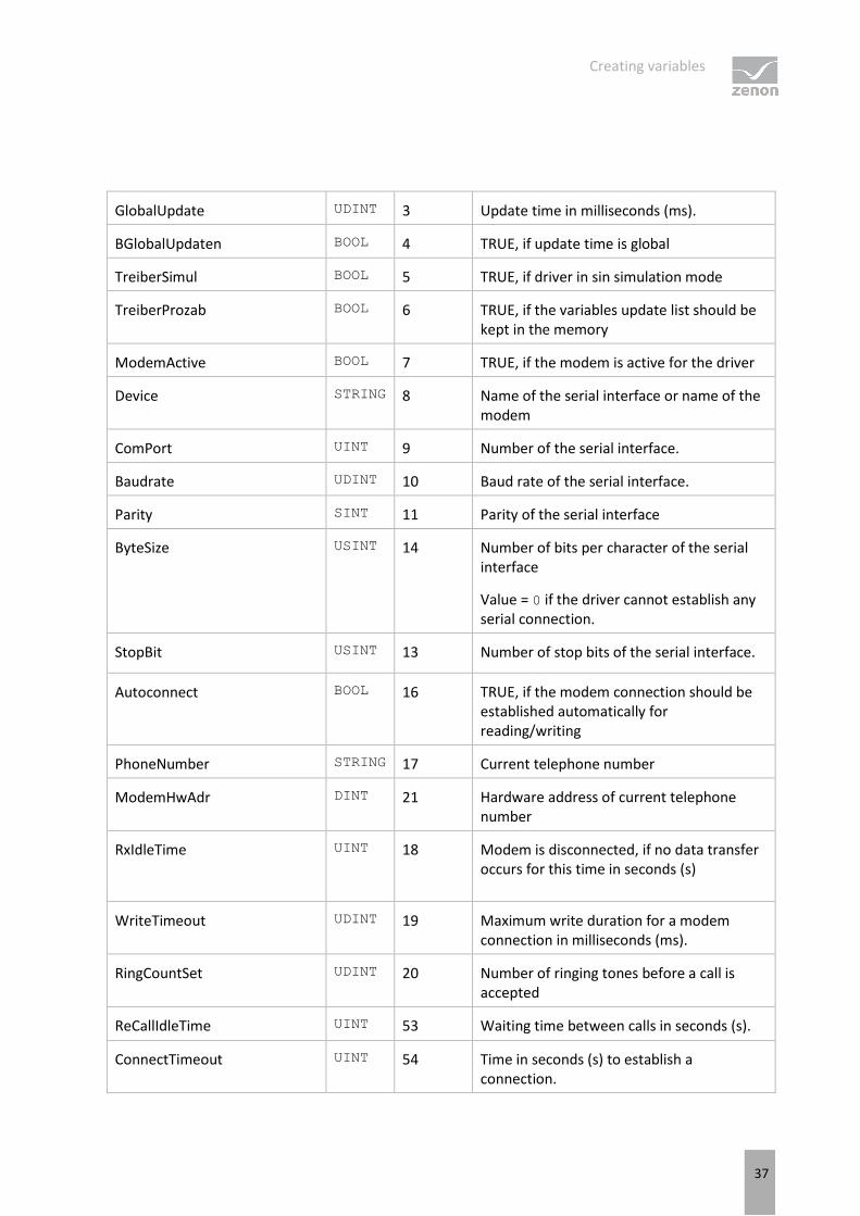
GlobalUpdate UDINT 3 Update time in milliseconds (ms).
BGlobalUpdaten BOOL 4 TRUE, if update time is global
TreiberSimul BOOL 5 TRUE, if driver in sin simulation mode
TreiberProzab BOOL 6 TRUE, if the variables update list should be kept in the memory
ModemActive BOOL 7 TRUE, if the modem is active for the driver
Device STRING 8 Name of the serial interface or name of the modem
ComPort UINT 9 Number of the serial interface.
Baudrate UDINT 10 Baud rate of the serial interface.
Parity SINT 11 Parity of the serial interface
ByteSize USINT 14 Number of bits per character of the serial interface
Value = 0 if the driver cannot establish any serial connection.
StopBit USINT 13 Number of stop bits of the serial interface.
Autoconnect BOOL 16 TRUE, if the modem connection should be established automatically for reading/writing
PhoneNumber STRING 17 Current telephone number
ModemHwAdr DINT 21 Hardware address of current telephone number
RxIdleTime UINT 18 Modem is disconnected, if no data transfer occurs for this time in seconds (s)
WriteTimeout UDINT 19 Maximum write duration for a modem connection in milliseconds (ms).
RingCountSet UDINT 20 Number of ringing tones before a call is accepted
ReCallIdleTime UINT 53 Waiting time between calls in seconds (s).
ConnectTimeout UINT 54 Time in seconds (s) to establish a connection.
Creating variables
38
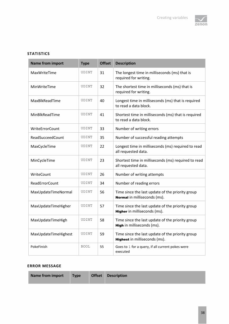
STATISTICS
Name from import Type Offset Description
MaxWriteTime UDINT 31 The longest time in milliseconds (ms) that is required for writing.
MinWriteTime UDINT 32 The shortest time in milliseconds (ms) that is required for writing.
MaxBlkReadTime UDINT 40 Longest time in milliseconds (ms) that is required to read a data block.
MinBlkReadTime UDINT 41 Shortest time in milliseconds (ms) that is required to read a data block.
WriteErrorCount UDINT 33 Number of writing errors
ReadSucceedCount UDINT 35 Number of successful reading attempts
MaxCycleTime UDINT 22 Longest time in milliseconds (ms) required to read all requested data.
MinCycleTime UDINT 23 Shortest time in milliseconds (ms) required to read all requested data.
WriteCount UDINT 26 Number of writing attempts
ReadErrorCount UDINT 34 Number of reading errors
MaxUpdateTimeNormal UDINT 56 Time since the last update of the priority group Normal in milliseconds (ms).
MaxUpdateTimeHigher UDINT 57 Time since the last update of the priority group Higher in milliseconds (ms).
MaxUpdateTimeHigh UDINT 58 Time since the last update of the priority group High in milliseconds (ms).
MaxUpdateTimeHighest UDINT 59 Time since the last update of the priority group Highest in milliseconds (ms).
PokeFinish BOOL 55 Goes to 1 for a query, if all current pokes were
executed
ERROR MESSAGE
Name from import Type Offset Description
Driver-specific functions
39
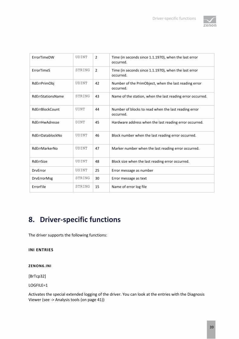
ErrorTimeDW UDINT 2 Time (in seconds since 1.1.1970), when the last error occurred.
ErrorTimeS STRING 2 Time (in seconds since 1.1.1970), when the last error occurred.
RdErrPrimObj UDINT 42 Number of the PrimObject, when the last reading error occurred.
RdErrStationsName STRING 43 Name of the station, when the last reading error occurred.
RdErrBlockCount UINT 44 Number of blocks to read when the last reading error occurred.
RdErrHwAdresse DINT 45 Hardware address when the last reading error occurred.
RdErrDatablockNo UDINT 46 Block number when the last reading error occurred.
RdErrMarkerNo UDINT 47 Marker number when the last reading error occurred.
RdErrSize UDINT 48 Block size when the last reading error occurred.
DrvError USINT 25 Error message as number
DrvErrorMsg STRING 30 Error message as text
ErrorFile STRING 15 Name of error log file
8. Driver-specific functions
The driver supports the following functions:
INI ENTRIES
ZENON6.INI
[BrTcp32]
LOGFILE=1
Activates the special extended logging of the driver. You can look at the entries with the Diagnosis Viewer (see -> Analysis tools (on page 41))
Driver commands
40
LIMITATIONS
If you deactivate the option "Keep PV update list in memory", requests will not be processed correctly, because in this case, the PLC will always return the last valid status.
There must always be at least one active variable per driver that is registered in the driver. Otherwise, the connection will not be used anymore and watchdogs etc. will no longer be sent.
9. Driver commands
This chapter describes standard functions that are valid for most zenon drivers. Not all functions described here are available for every driver. For example, a driver that does not, according to the data sheet, support a modem connection also does not have any modem functions.
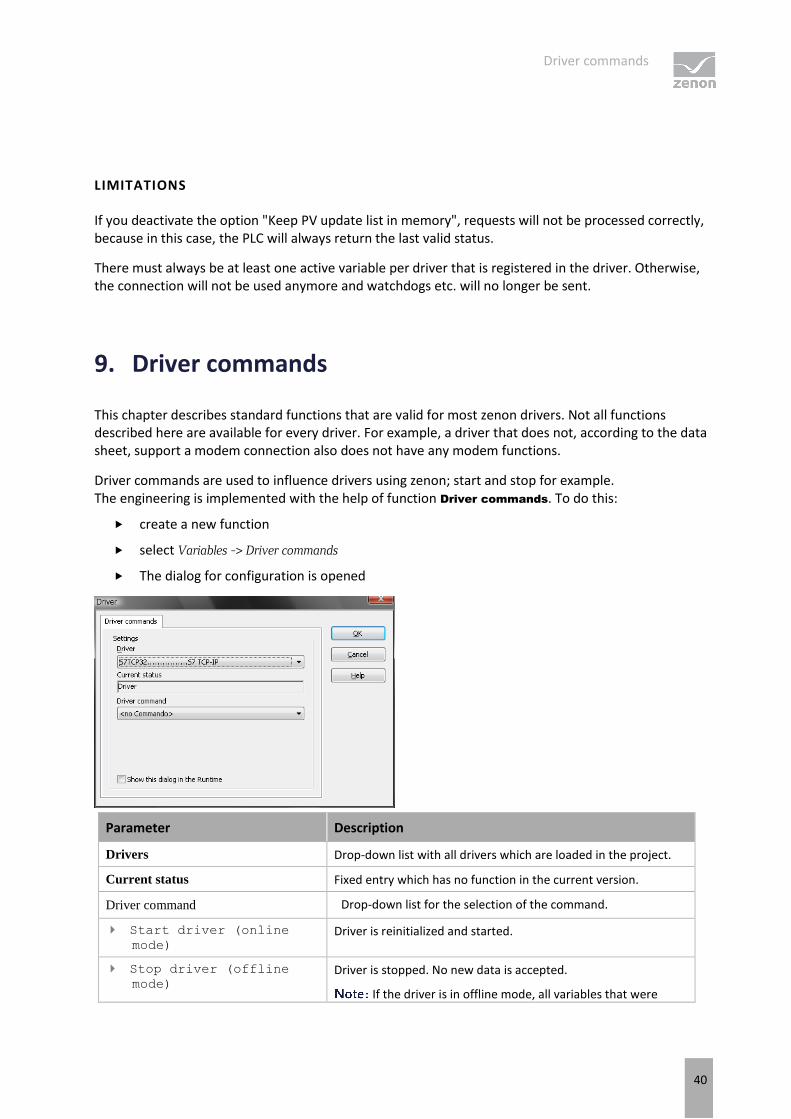
Driver commands are used to influence drivers using zenon; start and stop for example. The engineering is implemented with the help of function Driver commands. To do this:
create a new function
select Variables -> Driver commands
The dialog for configuration is opened
Parameter Description
Drivers Drop-down list with all drivers which are loaded in the project.
Current status Fixed entry which has no function in the current version.
Driver command Drop-down list for the selection of the command.
Start driver (online mode)
Driver is reinitialized and started.
Stop driver (offline mode)
Driver is stopped. No new data is accepted.
If the driver is in offline mode, all variables that were
Error analysis
41
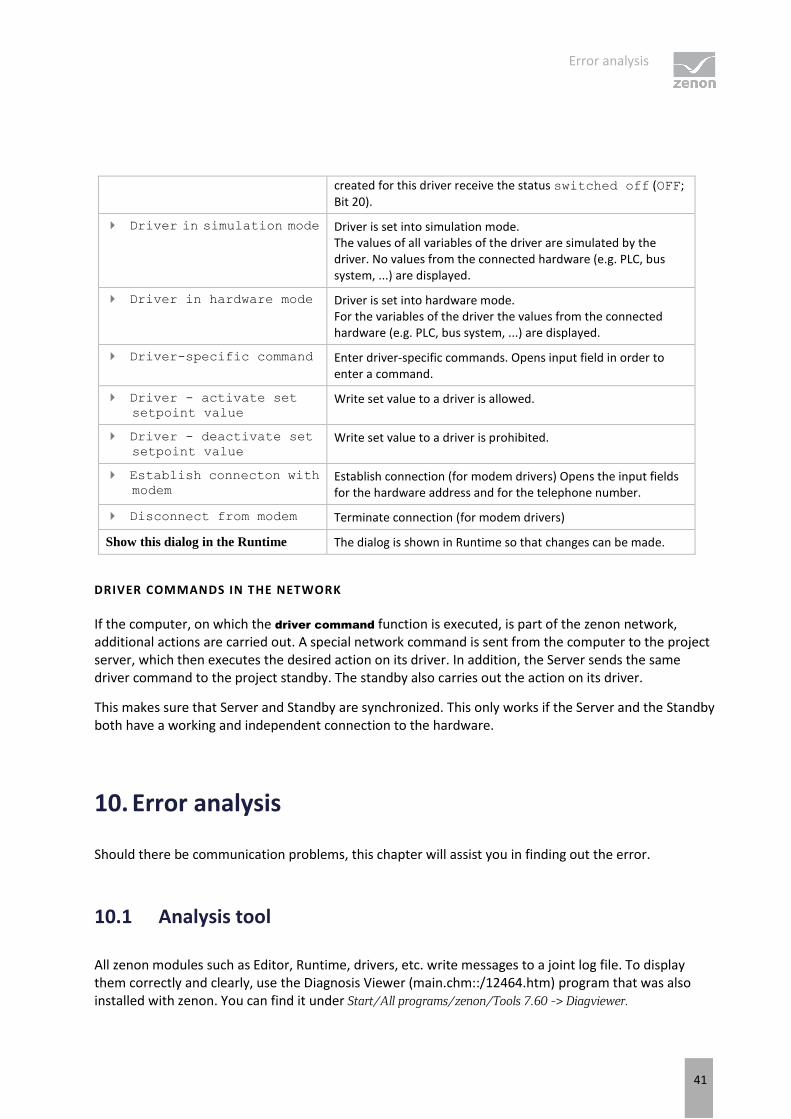
created for this driver receive the status switched off (OFF; Bit 20).
Driver in simulation mode Driver is set into simulation mode. The values of all variables of the driver are simulated by the driver. No values from the connected hardware (e.g. PLC, bus system, ...) are displayed.
Driver in hardware mode Driver is set into hardware mode. For the variables of the driver the values from the connected hardware (e.g. PLC, bus system, ...) are displayed.
Driver-specific command Enter driver-specific commands. Opens input field in order to enter a command.
Driver - activate set setpoint value
Write set value to a driver is allowed.
Driver - deactivate set setpoint value
Write set value to a driver is prohibited.
Establish connecton with modem
Establish connection (for modem drivers) Opens the input fields for the hardware address and for the telephone number.
Disconnect from modem Terminate connection (for modem drivers)
Show this dialog in the Runtime The dialog is shown in Runtime so that changes can be made.
DRIVER COMMANDS IN THE NETWORK
If the computer, on which the driver command function is executed, is part of the zenon network, additional actions are carried out. A special network command is sent from the computer to the project server, which then executes the desired action on its driver. In addition, the Server sends the same driver command to the project standby. The standby also carries out the action on its driver.
This makes sure that Server and Standby are synchronized. This only works if the Server and the Standby both have a working and independent connection to the hardware.
10. Error analysis
Should there be communication problems, this chapter will assist you in finding out the error.
10.1 Analysis tool
All zenon modules such as Editor, Runtime, drivers, etc. write messages to a joint log file. To display them correctly and clearly, use the Diagnosis Viewer (main.chm::/12464.htm) program that was also installed with zenon. You can find it under Start/All programs/zenon/Tools 7.60 -> Diagviewer.
Error analysis
42
zenon driver log all errors in the LOG files. LOG files are text files with a special structure. The default folder for the LOG files is subfolder LOG in the folder ProgramData. For example:
%ProgramData%\COPA-DATA\LOG.
With the default settings, a driver only logs error information. With the Diagnosis Viewer you can enhance the diagnosis level for most of the drivers to "Debug" and "Deep Debug". With this the driver also logs all other important tasks and events.
In the Diagnosis Viewer you can also:
Follow newly-created entries in real time
customize the logging settings
change the folder in which the LOG files are saved
1. The Diagnosis Viewer displays all entries in UTC (coordinated world time) and not in local time.
2. The Diagnosis Viewer does not display all columns of a LOG file per default. To display more columns activate property Add all columns with entry in the context menu of the column header.
3. If you only use Error-Logging, the problem description is in the column Error text. For other diagnosis level the description is in the column General text.
4. For communication problems many drivers also log error numbers which the PLC assigns to them. They are displayed in Error text or Error code or Driver error parameter (1 and 2). Hints on the meaning of error codes can be found in the driver documentation and the protocol/PLC description.
5. At the end of your test set back the diagnosis level from Debug or Deep Debug. At Debug and Deep Debug there are a great deal of data for logging which are saved to the hard drive and which can influence your system performance. They are still logged even after you close the Diagnosis Viewer.
Attention
In Windows CE errors are not logged per default due to performance reasons.
You can find further information on the Diagnosis Viewer in the Diagnose Viewer (main.chm::/12464.htm) manual.
Error analysis
43
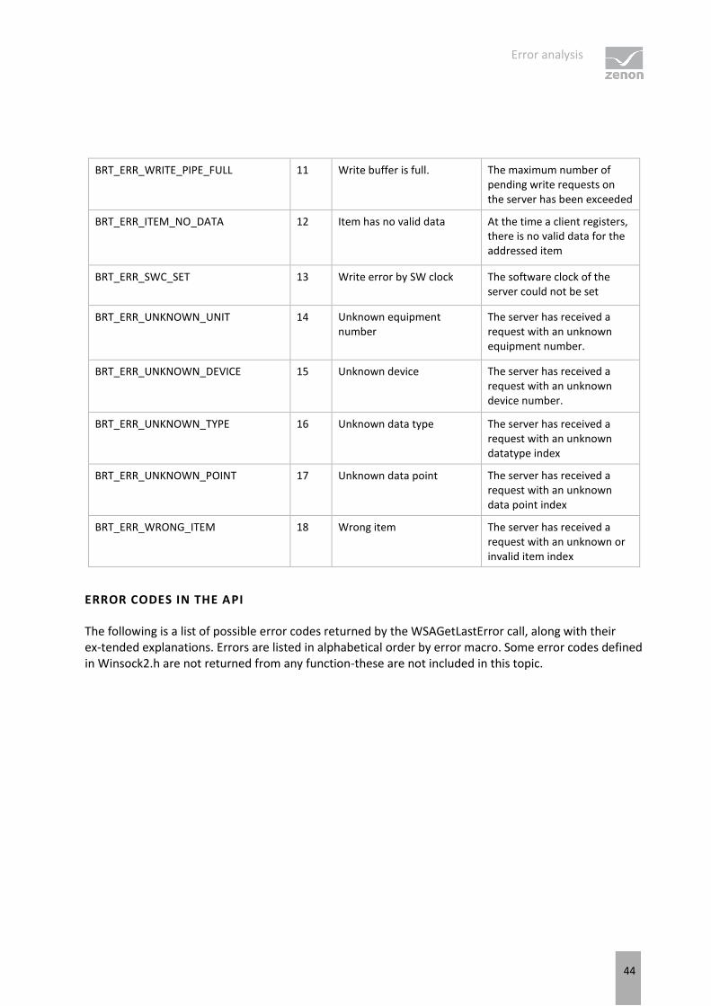
10.2 Error numbers
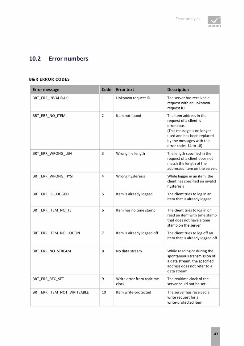
B&R ERROR CODES
Error message Code Error text Description
BRT_ERR_INVALIDAK 1 Unknown request ID The server has received a request with an unknown request ID.
BRT_ERR_NO_ITEM 2 Item not found The item address in the request of a client is erroneous (This message is no longer used and has been replaced by the messages with the error codes 14 to 18)
BRT_ERR_WRONG_LEN 3 Wrong file length The length specified in the request of a client does not match the length of the addressed item on the server.
BRT_ERR_WRONG_HYST 4 Wrong hysteresis While loggin in an item, the client has specified an invalid hysteresis
BRT_ERR_IS_LOGGED 5 Item is already logged The client tries to log in an item that is already logged
BRT_ERR_ITEM_NO_TS 6 Item has no time stamp The client tries to log in or read an item with time stamp that does not have a time stamp on the server
BRT_ERR_ITEM_NO_LOGON 7 Item is already logged off The client tries to log off an item that is already logged off
BRT_ERR_NO_STREAM 8 No data stream While reading or during the spontaneous transmission of a data stream, the specified address does not refer to a data stream
BRT_ERR_RTC_SET 9 Write error from realtime clock
The realtime clock of the server could not be set
BRT_ERR_ITEM_NOT_WRITEABLE 10 Item write-protected The server has received a write request for a write-protected item
Error analysis
44
BRT_ERR_WRITE_PIPE_FULL 11 Write buffer is full. The maximum number of pending write requests on the server has been exceeded
BRT_ERR_ITEM_NO_DATA 12 Item has no valid data At the time a client registers, there is no valid data for the addressed item
BRT_ERR_SWC_SET 13 Write error by SW clock The software clock of the server could not be set
BRT_ERR_UNKNOWN_UNIT 14 Unknown equipment number
The server has received a request with an unknown equipment number.
BRT_ERR_UNKNOWN_DEVICE 15 Unknown device The server has received a request with an unknown device number.
BRT_ERR_UNKNOWN_TYPE 16 Unknown data type The server has received a request with an unknown datatype index
BRT_ERR_UNKNOWN_POINT 17 Unknown data point The server has received a request with an unknown data point index
BRT_ERR_WRONG_ITEM 18 Wrong item The server has received a request with an unknown or invalid item index
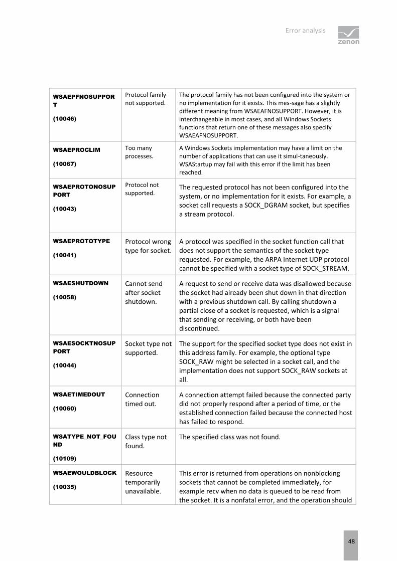
ERROR CODES IN THE API
The following is a list of possible error codes returned by the WSAGetLastError call, along with their ex-tended explanations. Errors are listed in alphabetical order by error macro. Some error codes defined in Winsock2.h are not returned from any function-these are not included in this topic.
Error analysis
45
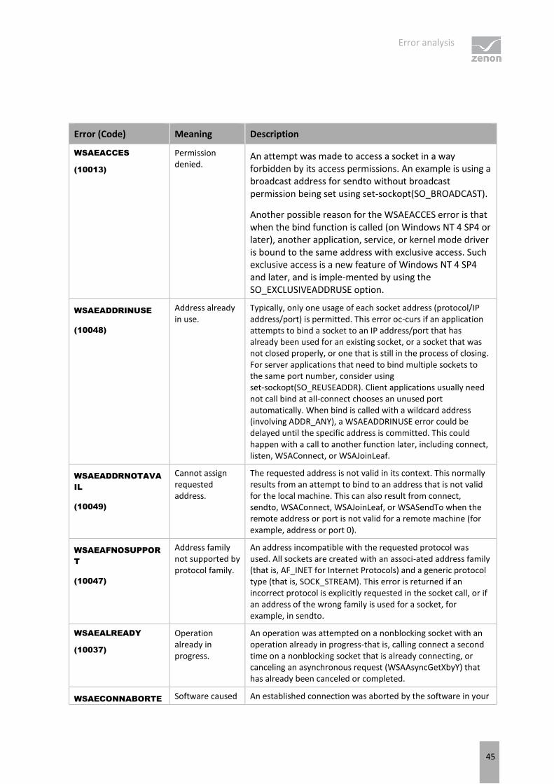
Error (Code) Meaning Description
WSAEACCES
(10013)
Permission denied.
An attempt was made to access a socket in a way forbidden by its access permissions. An example is using a broadcast address for sendto without broadcast permission being set using set-sockopt(SO_BROADCAST).
Another possible reason for the WSAEACCES error is that when the bind function is called (on Windows NT 4 SP4 or later), another application, service, or kernel mode driver is bound to the same address with exclusive access. Such exclusive access is a new feature of Windows NT 4 SP4 and later, and is imple-mented by using the SO_EXCLUSIVEADDRUSE option.
WSAEADDRINUSE
(10048)
Address already in use.
Typically, only one usage of each socket address (protocol/IP address/port) is permitted. This error oc-curs if an application attempts to bind a socket to an IP address/port that has already been used for an existing socket, or a socket that was not closed properly, or one that is still in the process of closing. For server applications that need to bind multiple sockets to the same port number, consider using set-sockopt(SO_REUSEADDR). Client applications usually need not call bind at all-connect chooses an unused port automatically. When bind is called with a wildcard address (involving ADDR_ANY), a WSAEADDRINUSE error could be delayed until the specific address is committed. This could happen with a call to another function later, including connect, listen, WSAConnect, or WSAJoinLeaf.
WSAEADDRNOTAVA
IL
(10049)
Cannot assign requested address.
The requested address is not valid in its context. This normally results from an attempt to bind to an address that is not valid for the local machine. This can also result from connect, sendto, WSAConnect, WSAJoinLeaf, or WSASendTo when the remote address or port is not valid for a remote machine (for example, address or port 0).
WSAEAFNOSUPPOR
T
(10047)
Address family not supported by protocol family.
An address incompatible with the requested protocol was used. All sockets are created with an associ-ated address family (that is, AF_INET for Internet Protocols) and a generic protocol type (that is, SOCK_STREAM). This error is returned if an incorrect protocol is explicitly requested in the socket call, or if an address of the wrong family is used for a socket, for example, in sendto.
WSAEALREADY
(10037)
Operation already in progress.
An operation was attempted on a nonblocking socket with an operation already in progress-that is, calling connect a second time on a nonblocking socket that is already connecting, or canceling an asynchronous request (WSAAsyncGetXbyY) that has already been canceled or completed.
WSAECONNABORTESoftware caused An established connection was aborted by the software in your
Error analysis
46
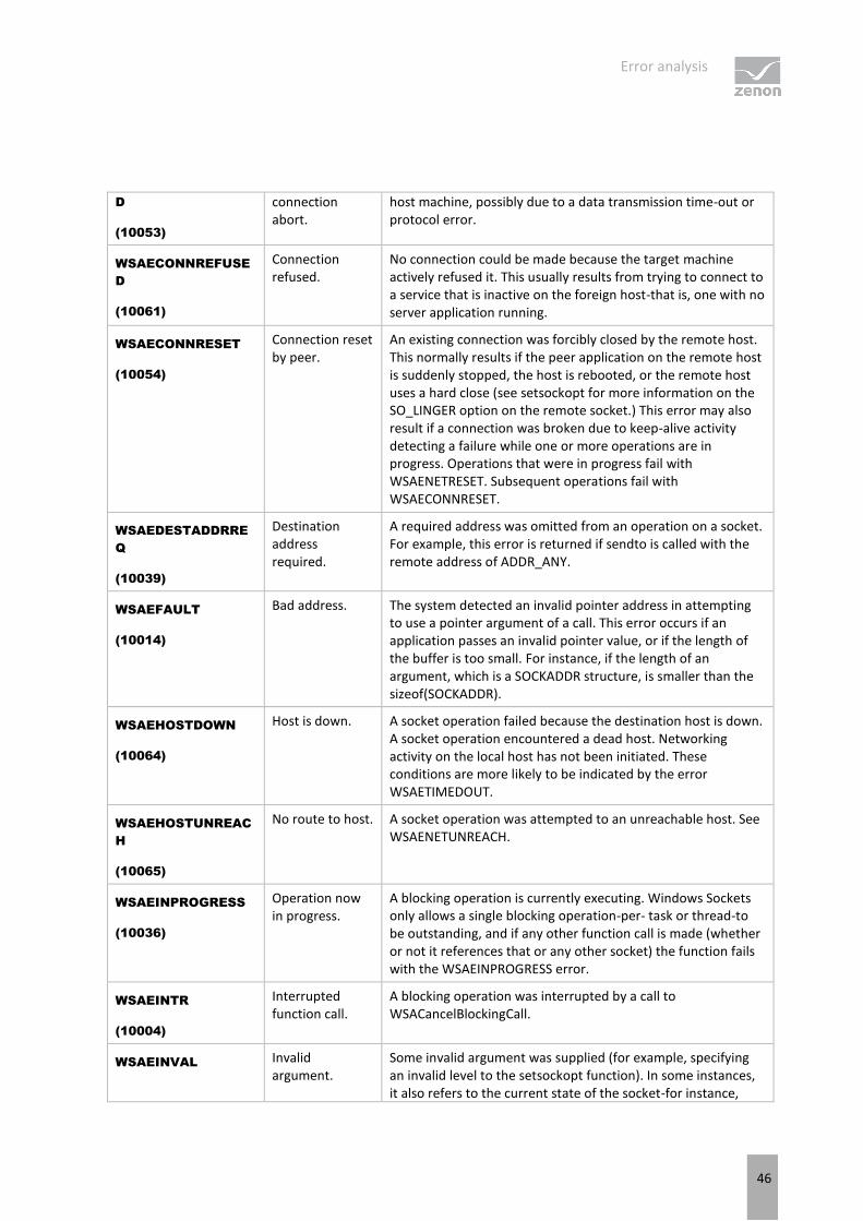
D
(10053)
connection abort.
host machine, possibly due to a data transmission time-out or protocol error.
WSAECONNREFUSE
D
(10061)
Connection refused.
No connection could be made because the target machine actively refused it. This usually results from trying to connect to a service that is inactive on the foreign host-that is, one with no server application running.
WSAECONNRESET
(10054)
Connection reset by peer.
An existing connection was forcibly closed by the remote host. This normally results if the peer application on the remote host is suddenly stopped, the host is rebooted, or the remote host uses a hard close (see setsockopt for more information on the SO_LINGER option on the remote socket.) This error may also result if a connection was broken due to keep-alive activity detecting a failure while one or more operations are in progress. Operations that were in progress fail with WSAENETRESET. Subsequent operations fail with WSAECONNRESET.
WSAEDESTADDRRE
Q
(10039)
Destination address required.
A required address was omitted from an operation on a socket. For example, this error is returned if sendto is called with the remote address of ADDR_ANY.
WSAEFAULT
(10014)
Bad address. The system detected an invalid pointer address in attempting to use a pointer argument of a call. This error occurs if an application passes an invalid pointer value, or if the length of the buffer is too small. For instance, if the length of an argument, which is a SOCKADDR structure, is smaller than the sizeof(SOCKADDR).
WSAEHOSTDOWN
(10064)
Host is down. A socket operation failed because the destination host is down. A socket operation encountered a dead host. Networking activity on the local host has not been initiated. These conditions are more likely to be indicated by the error WSAETIMEDOUT.
WSAEHOSTUNREAC
H
(10065)
No route to host. A socket operation was attempted to an unreachable host. See WSAENETUNREACH.
WSAEINPROGRESS
(10036)
Operation now in progress.
A blocking operation is currently executing. Windows Sockets only allows a single blocking operation-per- task or thread-to be outstanding, and if any other function call is made (whether or not it references that or any other socket) the function fails with the WSAEINPROGRESS error.
WSAEINTR
(10004)
Interrupted function call.
A blocking operation was interrupted by a call to WSACancelBlockingCall.
WSAEINVAL Invalid argument.
Some invalid argument was supplied (for example, specifying an invalid level to the setsockopt function). In some instances, it also refers to the current state of the socket-for instance,
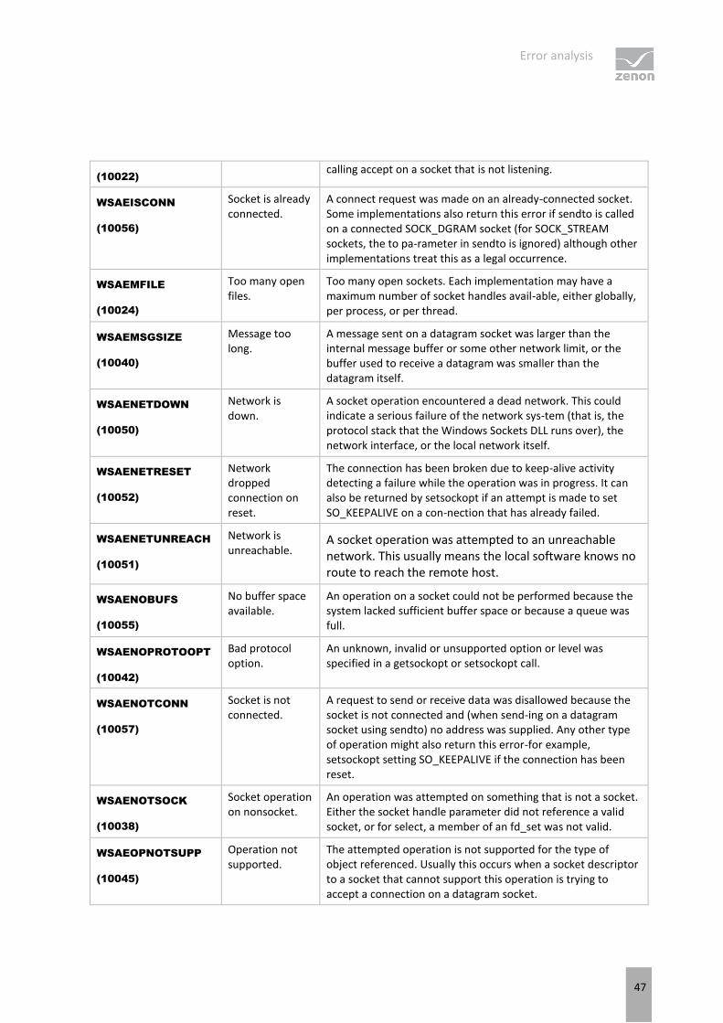
Error analysis
47
(10022) calling accept on a socket that is not listening.
WSAEISCONN
(10056)
Socket is already connected.
A connect request was made on an already-connected socket. Some implementations also return this error if sendto is called on a connected SOCK_DGRAM socket (for SOCK_STREAM sockets, the to pa-rameter in sendto is ignored) although other implementations treat this as a legal occurrence.
WSAEMFILE
(10024)
Too many open files.
Too many open sockets. Each implementation may have a maximum number of socket handles avail-able, either globally, per process, or per thread.
WSAEMSGSIZE
(10040)
Message too long.
A message sent on a datagram socket was larger than the internal message buffer or some other network limit, or the buffer used to receive a datagram was smaller than the datagram itself.
WSAENETDOWN
(10050)
Network is down.
A socket operation encountered a dead network. This could indicate a serious failure of the network sys-tem (that is, the protocol stack that the Windows Sockets DLL runs over), the network interface, or the local network itself.
WSAENETRESET
(10052)
Network dropped connection on reset.
The connection has been broken due to keep-alive activity detecting a failure while the operation was in progress. It can also be returned by setsockopt if an attempt is made to set SO_KEEPALIVE on a con-nection that has already failed.
WSAENETUNREACH
(10051)
Network is unreachable.
A socket operation was attempted to an unreachable network. This usually means the local software knows no route to reach the remote host.
WSAENOBUFS
(10055)
No buffer space available.
An operation on a socket could not be performed because the system lacked sufficient buffer space or because a queue was full.
WSAENOPROTOOPT
(10042)
Bad protocol option.
An unknown, invalid or unsupported option or level was specified in a getsockopt or setsockopt call.
WSAENOTCONN
(10057)
Socket is not connected.
A request to send or receive data was disallowed because the socket is not connected and (when send-ing on a datagram socket using sendto) no address was supplied. Any other type of operation might also return this error-for example, setsockopt setting SO_KEEPALIVE if the connection has been reset.
WSAENOTSOCK
(10038)
Socket operation on nonsocket.
An operation was attempted on something that is not a socket. Either the socket handle parameter did not reference a valid socket, or for select, a member of an fd_set was not valid.
WSAEOPNOTSUPP
(10045)
Operation not supported.
The attempted operation is not supported for the type of object referenced. Usually this occurs when a socket descriptor to a socket that cannot support this operation is trying to accept a connection on a datagram socket.
Error analysis
48
WSAEPFNOSUPPOR
T
(10046)
Protocol family not supported.
The protocol family has not been configured into the system or no implementation for it exists. This mes-sage has a slightly different meaning from WSAEAFNOSUPPORT. However, it is interchangeable in most cases, and all Windows Sockets functions that return one of these messages also specify WSAEAFNOSUPPORT.
WSAEPROCLIM
(10067)
Too many processes.
A Windows Sockets implementation may have a limit on the number of applications that can use it simul-taneously. WSAStartup may fail with this error if the limit has been reached.
WSAEPROTONOSUP
PORT
(10043)
Protocol not supported.
The requested protocol has not been configured into the system, or no implementation for it exists. For example, a socket call requests a SOCK_DGRAM socket, but specifies a stream protocol.
WSAEPROTOTYPE
(10041)
Protocol wrong type for socket.
A protocol was specified in the socket function call that does not support the semantics of the socket type requested. For example, the ARPA Internet UDP protocol cannot be specified with a socket type of SOCK_STREAM.
WSAESHUTDOWN
(10058)
Cannot send after socket shutdown.
A request to send or receive data was disallowed because the socket had already been shut down in that direction with a previous shutdown call. By calling shutdown a partial close of a socket is requested, which is a signal that sending or receiving, or both have been discontinued.
WSAESOCKTNOSUP
PORT
(10044)
Socket type not supported.
The support for the specified socket type does not exist in this address family. For example, the optional type SOCK_RAW might be selected in a socket call, and the implementation does not support SOCK_RAW sockets at all.
WSAETIMEDOUT
(10060)
Connection timed out.
A connection attempt failed because the connected party did not properly respond after a period of time, or the established connection failed because the connected host has failed to respond.
WSATYPE_NOT_FOU
ND
(10109)
Class type not found.
The specified class was not found.
WSAEWOULDBLOCK
(10035)
Resource temporarily unavailable.
This error is returned from operations on nonblocking sockets that cannot be completed immediately, for example recv when no data is queued to be read from the socket. It is a nonfatal error, and the operation should
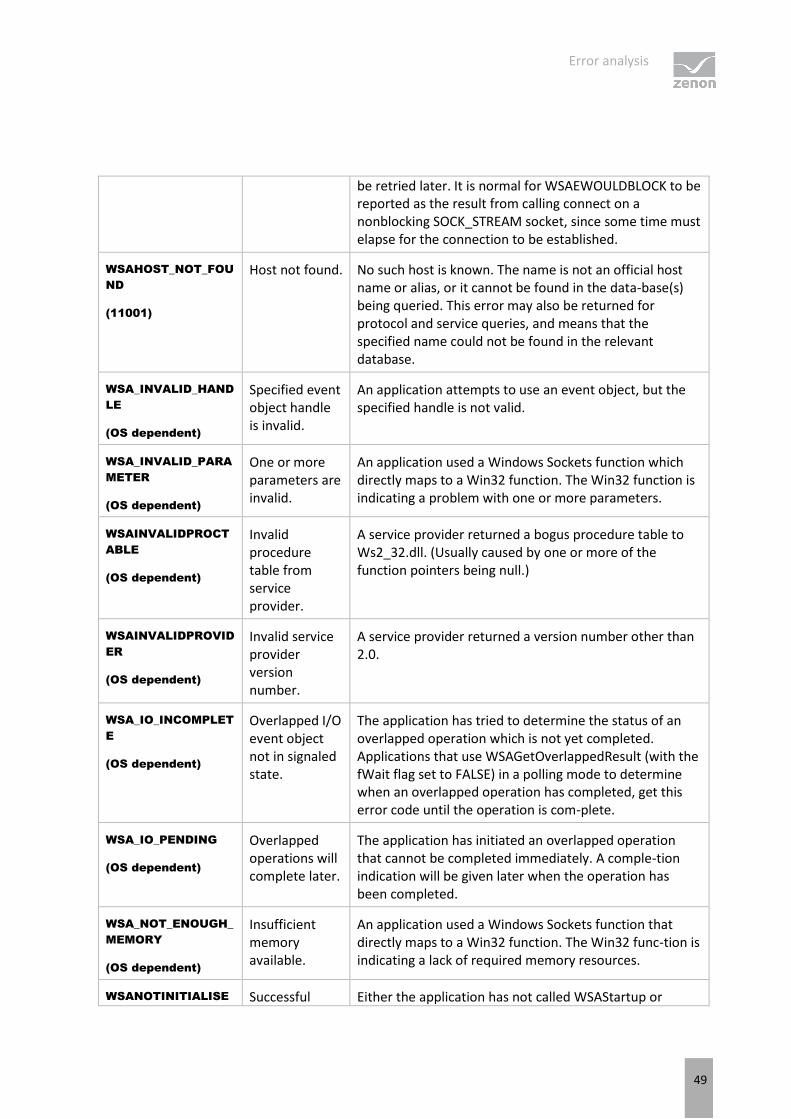
Error analysis
49
be retried later. It is normal for WSAEWOULDBLOCK to be reported as the result from calling connect on a nonblocking SOCK_STREAM socket, since some time must elapse for the connection to be established.
WSAHOST_NOT_FOU
ND
(11001)
Host not found. No such host is known. The name is not an official host name or alias, or it cannot be found in the data-base(s) being queried. This error may also be returned for protocol and service queries, and means that the specified name could not be found in the relevant database.
WSA_INVALID_HAND
LE
(OS dependent)
Specified event object handle is invalid.
An application attempts to use an event object, but the specified handle is not valid.
WSA_INVALID_PARA
METER
(OS dependent)
One or more parameters are invalid.
An application used a Windows Sockets function which directly maps to a Win32 function. The Win32 function is indicating a problem with one or more parameters.
WSAINVALIDPROCT
ABLE
(OS dependent)
Invalid procedure table from service provider.
A service provider returned a bogus procedure table to Ws2_32.dll. (Usually caused by one or more of the function pointers being null.)
WSAINVALIDPROVID
ER
(OS dependent)
Invalid service provider version number.
A service provider returned a version number other than 2.0.
WSA_IO_INCOMPLET
E
(OS dependent)
Overlapped I/O event object not in signaled state.
The application has tried to determine the status of an overlapped operation which is not yet completed. Applications that use WSAGetOverlappedResult (with the fWait flag set to FALSE) in a polling mode to determine when an overlapped operation has completed, get this error code until the operation is com-plete.
WSA_IO_PENDING
(OS dependent)
Overlapped operations will complete later.
The application has initiated an overlapped operation that cannot be completed immediately. A comple-tion indication will be given later when the operation has been completed.
WSA_NOT_ENOUGH_
MEMORY
(OS dependent)
Insufficient memory available.
An application used a Windows Sockets function that directly maps to a Win32 function. The Win32 func-tion is indicating a lack of required memory resources.
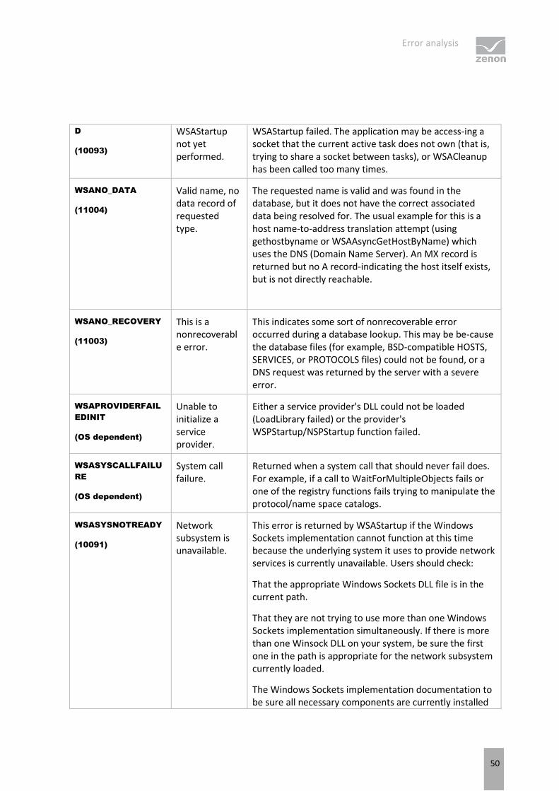
WSANOTINITIALISE Successful Either the application has not called WSAStartup or
Error analysis
50
D
(10093)
WSAStartup not yet performed.
WSAStartup failed. The application may be access-ing a socket that the current active task does not own (that is, trying to share a socket between tasks), or WSACleanup has been called too many times.
WSANO_DATA
(11004)
Valid name, no data record of requested type.
The requested name is valid and was found in the database, but it does not have the correct associated data being resolved for. The usual example for this is a host name-to-address translation attempt (using gethostbyname or WSAAsyncGetHostByName) which uses the DNS (Domain Name Server). An MX record is returned but no A record-indicating the host itself exists, but is not directly reachable.
WSANO_RECOVERY
(11003)
This is a nonrecoverable error.
This indicates some sort of nonrecoverable error occurred during a database lookup. This may be be-cause the database files (for example, BSD-compatible HOSTS, SERVICES, or PROTOCOLS files) could not be found, or a DNS request was returned by the server with a severe error.
WSAPROVIDERFAIL
EDINIT
(OS dependent)
Unable to initialize a service provider.
Either a service provider's DLL could not be loaded (LoadLibrary failed) or the provider's WSPStartup/NSPStartup function failed.
WSASYSCALLFAILU
RE
(OS dependent)
System call failure.
Returned when a system call that should never fail does. For example, if a call to WaitForMultipleObjects fails or one of the registry functions fails trying to manipulate the protocol/name space catalogs.
WSASYSNOTREADY
(10091)
Network subsystem is unavailable.
This error is returned by WSAStartup if the Windows Sockets implementation cannot function at this time because the underlying system it uses to provide network services is currently unavailable. Users should check:
That the appropriate Windows Sockets DLL file is in the current path.
That they are not trying to use more than one Windows Sockets implementation simultaneously. If there is more than one Winsock DLL on your system, be sure the first one in the path is appropriate for the network subsystem currently loaded.
The Windows Sockets implementation documentation to be sure all necessary components are currently installed
Error analysis
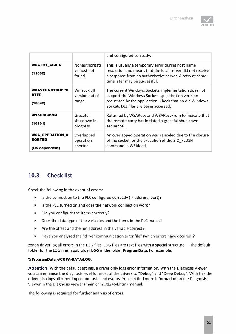
51
and configured correctly.
WSATRY_AGAIN
(11002)
Nonauthoritative host not found.
This is usually a temporary error during host name resolution and means that the local server did not receive a response from an authoritative server. A retry at some time later may be successful.
WSAVERNOTSUPPO
RTED
(10092)
Winsock.dll version out of range.
The current Windows Sockets implementation does not support the Windows Sockets specification ver-sion requested by the application. Check that no old Windows Sockets DLL files are being accessed.
WSAEDISCON
(10101)
Graceful shutdown in progress.
Returned by WSARecv and WSARecvFrom to indicate that the remote party has initiated a graceful shut-down sequence.
WSA_OPERATION_A
BORTED
(OS dependent)
Overlapped operation aborted.
An overlapped operation was canceled due to the closure of the socket, or the execution of the SIO_FLUSH command in WSAIoctl.
10.3 Check list
Check the following in the event of errors:
Is the connection to the PLC configured correctly (IP address, port)?
Is the PLC turned on and does the network connection work?
Did you configure the items correctly?
Does the data type of the variables and the items in the PLC match?
Are the offset and the net address in the variable correct?
Have you analyzed the "driver communication error file" (which errors have occured)?
zenon driver log all errors in the LOG files. LOG files are text files with a special structure. The default folder for the LOG files is subfolder LOG in the folder ProgramData. For example:
%ProgramData%\COPA-DATA\LOG.
With the default settings, a driver only logs error information. With the Diagnosis Viewer you can enhance the diagnosis level for most of the drivers to "Debug" and "Deep Debug". With this the driver also logs all other important tasks and events. You can find more information on the Diagnosis Viewer in the Diagnosis Viewer (main.chm::/12464.htm) manual.
The following is required for further analysis of errors:

Error analysis
52
The project backup
LOG files
Send these to your support person after agreement with the customer service department.


