Road Map for a 5000-ft Microborehole i
ROAD MAP FOR A 5000-FT MICROBOREHOLE
Jim Albright, Don Dreesen, Dave Anderson, and Jim Blacic, Los Alamos National LaboratoryJim Thomson, Lithos Associates and Tom Fairbanks, Nambe Geophysical, Inc.
EXECUTIVE SUMMARY
ABSTRACTIn 1994, Los Alamos National Laboratory (LANL) advanced a concept for drilling deep, small
holes with diameters from 2-3/8-in. to 1-3/8-in., for exploration holes, for reservoir monitoring,and for production of shallow- and medium-depth low-productivity reservoirs. This concept forcoiled-tubing-deployed microdrilling evolved from theoretical studies and lab tests, to fielddemonstrations in which 1-3/4- and 2-3/8-in.-diameter holes were drilled to 700-ft deep. Thisdesign, developed with input from industrial collaborators and subcontractors, derives primarilyfrom technologies and practices that are both familiar and in some use for drilling larger diameterwells. As a result of our experience, we believe that drilling microholes to depths of 5000 ft canbe achieved with relatively modest modification of existing drilling equipment and coiled tubingtechnology. We prepared a draft Road Map. Industry input is now needed to add a commercialperspective and reality to this Road Map, and to bring potential users and providers into theprocess. The motivation for developing microhole technology is the potential for a significantreduction of both the cost and environmental impact of drilling. Industry evaluation andparticipation in a final draft of the Road Map is a prerequisite for moving this effort forward.
CONTENTSAbstract 1Introduction 1Background 2Initial Microdrilling Rig Concept 4Well Construction and Completion 7Industry Input to the Initial Concept 8Field Demonstrations Results 10What We Can Do Now 13Adapting the Initial Concept Based on Field Operations Results 13Missing Sub-Components and needed Technology 14Hydraulics and Drilling Fluids 15
Downhole Drilling Sensors and Controls 17Downhole Trajectory Sensors and Directional Drilling Controls 18Logging Tools 18Telemetry 18Completion Technology 19
Concept Design for 5000-ft Deep Microholes 19The Roadmap 27Needed Technology Development 27Less Critical Technology Needed 30Microdrilling Platform for Drilling Demonstrations 32Drill Sites for Demonstrations 34Conclusions 34References 35Appendix - Field Drilling Demonstrations 36
Road Map for a 5000-ft Microborehole ii
BACKGROUNDThe idea of drilling holes as small as 1-in. diameter in the deep earth is not new. Relatively
deep, small-diameter holes as small as 1.175-in. have been drilled using mining coring rigs for atleast 50 years. Oil industry attempts to adapt mining core-drilling technology to produceinexpensive slimholes, while technically successful, did not find widespread commercial usebecause infrastructure costs could only be modestly reduced. However, coiled-tubing-deployeddrilling for cleanout and laterals has found some acceptance in petroleum drilling and explorationover the last decade. Major components of a capable infrastructure have already been created forcoiled-tubing drilling. Coiled-tubing technology is thus a likely enabling technology forsignificant cost reductions for wells drilled from the surface.
The combination of coiled-tubing-deployed and microhole-drilling concepts may provide amethod to greatly reduce the cost of drilling shallow- and moderate-depth holes for exploration,long-term monitoring, and limited production service. The availability of small sensors andtelemetry instrumentation to mine information from microholes changed the paradigm since theslimhole-drilling development reached it peak. The equipment needed to construct microholesthat are less than one fourth the diameter of a typical conventional-sized hole can be drilled withequipment that will weigh less than one tenth as much as conventional equipment. The smallerequipment can be handled with less manpower, and a designed-for-purpose, fully automated,coiled-tubing-deployed drilling system would maximize the potential for reducing labor andequipment costs.
There is one obvious roadblock that will tend to deter the commercialization of coiled-tubingmicrodrilling (or other competing concepts for microdrilling), by independent, small servicecompanies that have historically lead innovations in drilling technology. That is, the inevitablefact that a large number of related services has to be developed in parallel with the basic drillingcapability. These include, (but are not limited to): associated drilling support (i.e. sidetracking,directional drilling, underbalanced drilling, formation testing, and fishing), well completion andperforating equipment, logging tools, and instrumented well technology, and artificial liftequipment—all of which can be applied to a microhole size. Without the evolution of asignificant number of these capabilities for microholes, microdrilling technology has very limitedcommercial value.
MICRODRILLING CONCEPTThe basic microdrilling-rig concept was developed by LANL to achieve a readily automated
drilling model that avoids the more complicated and labor-intensive aspects of conventional oil-field drilling, and reduces the size of the rig required for drilling and completing the microbore.The coiled-tubing-deployed drill was selected to provide an inexpensive, reliable, hard-wired,bottom-hole data and control telemetry. The basic, built-for-purpose coiled-tubing-unit (CTU)microrig must be readily adaptable to support low-cost directional drilling and through-tubingmicro-lateral drilling from existing wells. The drilling system must also be suitable for drillingwith low density, compressible drilling fluids to penetrate depleted reservoirs, and to search forand produce bypassed oil and gas. The CTU design will facilitate quick reel changes in the fieldin order to support hole-size reduction with a comparable reduction in the tubing diameter.
The basic LANL drilling assembly concept assumes a properly designed, polycrystallinediamond compact (PDC) or thermally stable, polycrystalline diamond (TSD) drag bit will berotated by a relatively high speed Moineau-principle, positive-displacement (drilling) motor(PDM) that can rapidly penetrate most oilfield rock with low weight-on-bit. A robust,instrumented, near-bit-sensor sub located below the motor will support the automation andcontrol of the bottom-hole drilling assembly. An isolation sub above the motor will protect a lessrobust telemetry instrumentation sub and the coiled tubing from pulsations and vibrationsgenerated in the drilling assembly.
Road Map for a 5000-ft Microborehole iii
The coiled-tubing diameter will be sized relative to the bit size to optimize hydraulic powertransport and maximize drilling thrust (weight-on-bit) that can be applied by drill stemcompression. In order to transport sufficient power to achieve high penetration rates, the microrighydraulics must operate at relatively high pressure and low flow to minimize power losses. Thedevelopment of compatible, microsized rotary-drilling motors is a critical element of the drillingsystem. Very hard rock that cannot be effectively penetrated using PDC bits will require analternate drill assembly; a rotary percussion system is believed to be the most promisingtechnology for low thrust, hard rock drilling, but commercially available equipment is not wellsuited for openhole coiled-tubing drilling. Drill-cuttings transport in a very narrow annulus willbe a significant challenge that has not been completely resolved for highly inclined, conventional-sized bores using coiled-tubing (slide) drilling.
WELL CONSTRUCTION AND COMPLETION CONCEPTTo support drilling to 5000 ft, a well-construction concept must include a conductor-pipe
surface-casing to isolate fresh water aquifers, intermediate casings if required, and a finalproduction casing (or liner) or a stable openhole to support exploration logging and formationtesting. Where feasible, the coiled tubing used to drill the surface, intermediate, and productionholes may be expended to serve as the surface and intermediate casing since the drill conceptassumes a relatively large ratio of the drill-stem-to-hole diameter. Each size of tubing isconverted from drill stem to casing by removing the drilling assembly, and installing a bottom-hole-cementing assembly and casing centralizers clamped to the coiled tubing. The casing iswashed to bottom, landed and hung-off in a wellhead, cut off from the remaining reeled tubing,and cemented. The next smaller reel of continuous drill stem is then drilled down to its intendedshoe depth and converted to casing in a similar manner to produce a cased hole or openholecompletion across the target reservoir or exploration target. To achieve a 5000-ft depth withprovision for surface and intermediate casing, drilling of holes as small a 1-3/8-in.-diameter isproposed to keep the rig size for a 5000-ft capability to a minimum. The well designs proposedin the full Road Map do not incorporate the expandable openhole casings and liners that haverecently been successfully demonstrated in the field. The expansion of microsized tubing/casingand coiled tubing will increase the potential depth of the microdrilling capability, and decreasethe rig-size requirements, in the same way this technology impacts conventional-sized drilling.
Perforators that can be run on small mono-cable wirelines or coiled tubing will be needed, aswell as stimulation technology suitable for low-flow treatments. The coiled tubing can beinserted as a tubing string after logging, perforating, and stimulation are completed.
FIELD DEMONSTRATION RESULTSThe coiled-tubing-deployed microdrilling concept was successfully demonstrated at three
sites: the Fenton Hill Demonstration Site near Los Alamos, a site with Basin and Range Dry-Lake-Bed Sediments in support of an industrial sponsor, and the San Ysidro Site in SandovalCounty, NM. Based on local outcrops, it was anticipated that the San Ysidro site would providethe first application of the LANL microdrilling system to typical oil-field rocks. As it turned out,the site provided significant challenges including artesian flow, loss of returns, and severe wellinstability in poorly consolidated sediments, but did not provide strata of relatively hardsandstones and shales that we had anticipated. Where resources were available, most of thedrilling problems encountered were mitigated using rather conventional approaches that arecommonly applied in conventional-sized holes. All of the demonstrations have been conductedwith daylight drilling and shutdowns each night and most weekends. Both the schedule andequipment failures contributed to the bore instability problems encountered. The problem withexcessive hole-washouts at the San Ysidro site has not yet been fully mitigated. We believe thatthe development of a low-flow, high-differential-pressure drilling motor, and continuous drilling
Road Map for a 5000-ft Microborehole iv
operations to penetrate and promptly isolate the problem formations, will mitigate the severewash out problem we experienced.
Los Alamos presently has the capability to drill 1-3/4-in. and 2-3/8-in. holes up to 800-ft deepin unconsolidated and soft sediments with commercial PDMs where our current limitation is reelsize. We can complete the holes with a cemented-in casing in stable formations, and havedemonstrated that we can install casing in unstable formations, and seal it in with a bentonitegrout.
TECHNOLOGY NEEDSBased on our field drilling experience, a list of modifications needed to improve the original
drilling concept was identified. The modifications, described in the full Road Map document, donot require significant new technology development to improve the ability to drill microholes to1000 ft.
In order to reach a moderate depth of the order of 5000 ft with a low-cost, high-performance,drilling system, some development of new technology (as described in the Road Map) is required.New technology development falls into three areas: (1) optimization of drilling hydraulics,cuttings transport, and bore-wall stabilization; (2) enhancement of drilling motors and rotarypercussion hammers with compatible isolation tools; (3) downsizing downhole sensors,instrumentation, and telemetry needed to support automated drilling, real-time steering, and log-while-drilling.
Technology requirements for well logging, reservoir monitoring, and exploration aredescribed in other LANL publications. They are not addressed in detail in the Road Map, butrelevant publications are included in the references. Technology requirements for microholecompletions include downsizing perforation technology, and downhole cementing equipment forboth coupled casing and continuous (coiled-tubing) casing.
CONCLUSIONS1. A concept for drilling to 5000 ft in sediments with a coiled-tubing-deployed microdrilling
system has been developed and evaluated using modeling, laboratory tests, and shallow fielddemonstrations. Major components of the technology are familiar and in current use in thedrilling of conventional-sized wells and laterals.
2. Some technology development is needed to downsize existing drilling equipment tomicrohole dimensions, and to develop new equipment for drilling deeper and optimizing thedrilling performance at 5000 ft.
3. A $20-million, five-year technology-development program has been outlined in the full RoadMap that proposes to demonstrate near-vertical rotary drilling using rental surface equipmentand prototype downhole equipment in three years, and evaluates the possibility of expandingto percussion and air drilling using a prototype surface system within five years.
Road Map for a 5000-ft Microborehole v
Task Name
DOE NPTO Microdrilling Systems Project
DOE NPTO Workshop
DOE NPTO Solicitation
DOE NPTO Contracting
A Critical Miniturization and Technology Development
Downsize existing equipment to fit in micro boreholes
1) Microdrill Motor
a) Rotary PDM
b) Rotary Percussion Motor
2) Microdrill Bits
a) PDC rotary bits
b) Percussion hammer bits
3) Downhole Instrumentation and Controls
a) Existing downhole sensors & telemetry
b) Downhole directional drilling controls
4) Micro-Casing Installation and Cementing
a) Cementing tools
b) Cement slurries
5) Micro-Production and Monitoring
a) Perforation tools
b) Gravel packing
c) Simulation
B Less Critical Technology
Modify or develop new technology to optimize performance
1) High Pressure Mud Pumps
2) Advanced drilling fluid cleaning
3) Coiled-tubing fabrication
4) Coiled-tubing deployed fishing
5) Power and cutting transport model
6) Microdrill air motor
C Systems Engineering and Demonstrations
Design, procure, assemble, test and demonstrate microdrill
1) Vertical Coiled-Tubing-Deployed Drilling System
a) Design/select rig components
b) demonstrate 5000 ft hole
2) Directional and Percussion Coiled-Tubing-Deployed Drill
a) Modify rig components
b) Demonstrate directional and percussion
3) Underbalanced Drilling Demonstration
a) Design rig components to support air
b) Demonstrate air drilling
1 2 3 4 1 2 3 4 1 2 3 4 1 2 3 4 1 2 3 4 1 2 3 4 1 2
2003 2004 2005 2006 2007 2008 2009
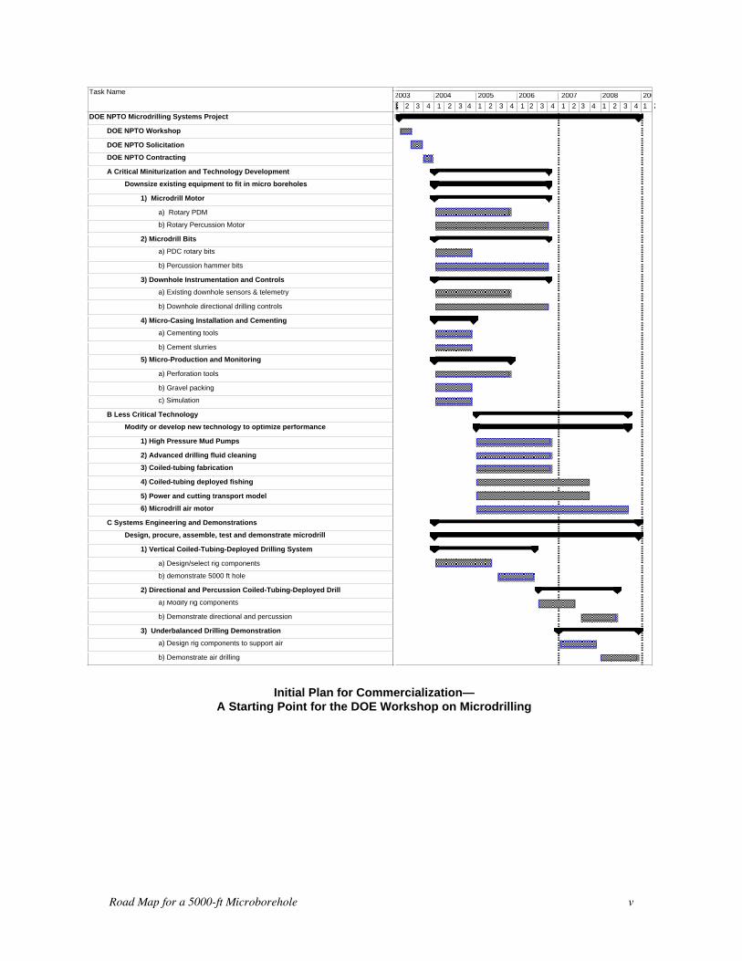
Initial Plan for Commercialization—A Starting Point for the DOE Workshop on Microdrilling
Road Map for a 5000-ft Microborehole 1
ROAD MAP FOR A 5000-FT MICROBOREHOLE
ABSTRACT
In 1994 Los Alamos National Laboratory advanced a concept for drilling deep, small-diameter holesfor sensor deployment to conduct long-term monitoring. We believed that microsized acousticsensors, fluid samplers, and other appropriate monitoring instrumentation could be deployed in or nearproducing reservoirs, and would be economically attractive for long-term, reservoir monitoring. Theidea quickly expanded to include exploration holes for formation logging, wireline or drill-stem-deployed logging, and microdrill-stem production testing. More recently, microholes have beenconsidered for production of shallow- and medium-depth gas and shallow oil in special situations. Themicrodrilling concept has evolved from theoretical studies and laboratory tests of microhole drillingcapabilities to demonstrations up to 700-ft deep in soft rock and unconsolidated formations. Derivingfrom this experience the US Department of Energy in cooperation with industry has begun exploringthe feasibility of drilling microholes to 5000 ft for a variety of applications. To this end, Los AlamosNational Laboratory has been asked to prepare a Road Map for development of microhole technology.
The Road Map is intended to serve as the guide for developing the technical capability for drilling andcompletion of 5000-ft deep microholes with an openhole diameter of approximately 1-3/8 in. at totaldepth before casing and l-in. diameter after casing. We summarize the necessary oil industry supportand identify the needs and technical challenges confronting the development of this technology.
INTRODUCTION
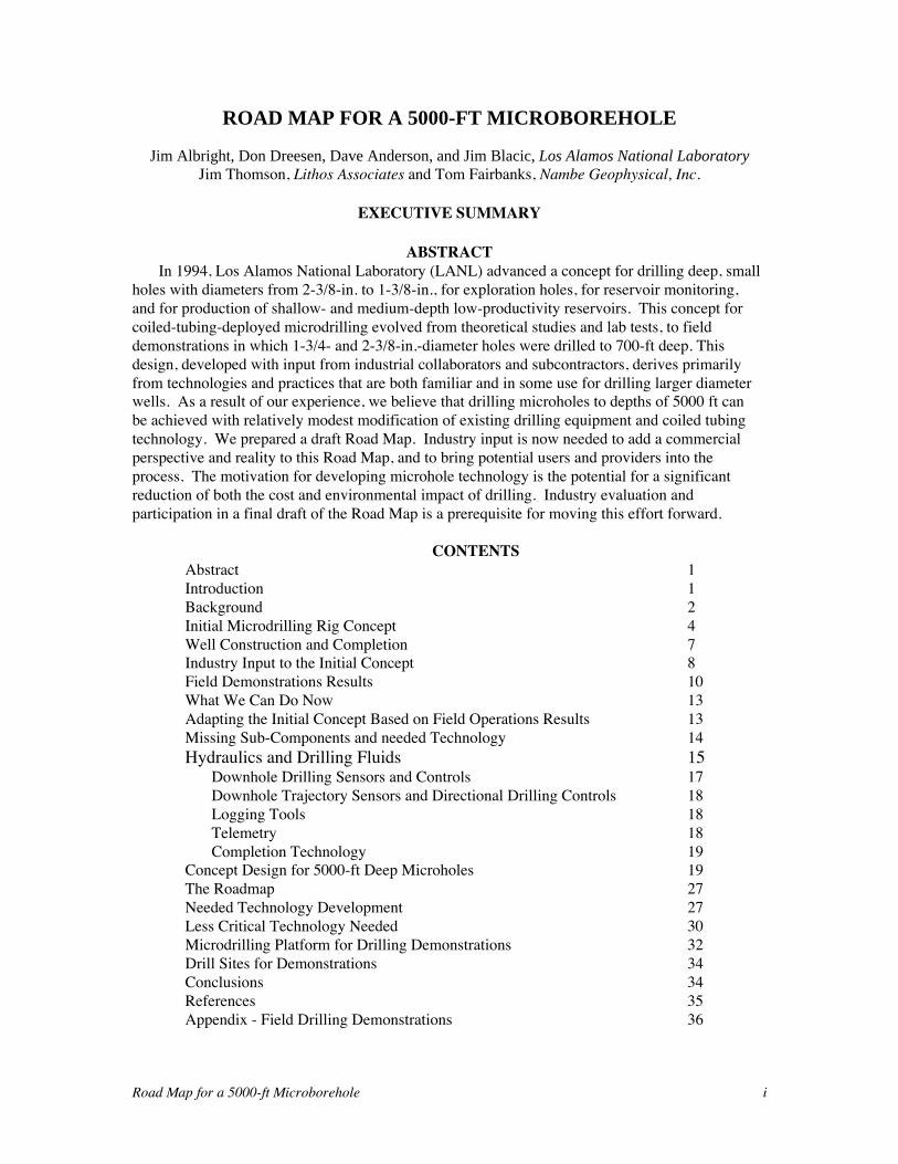
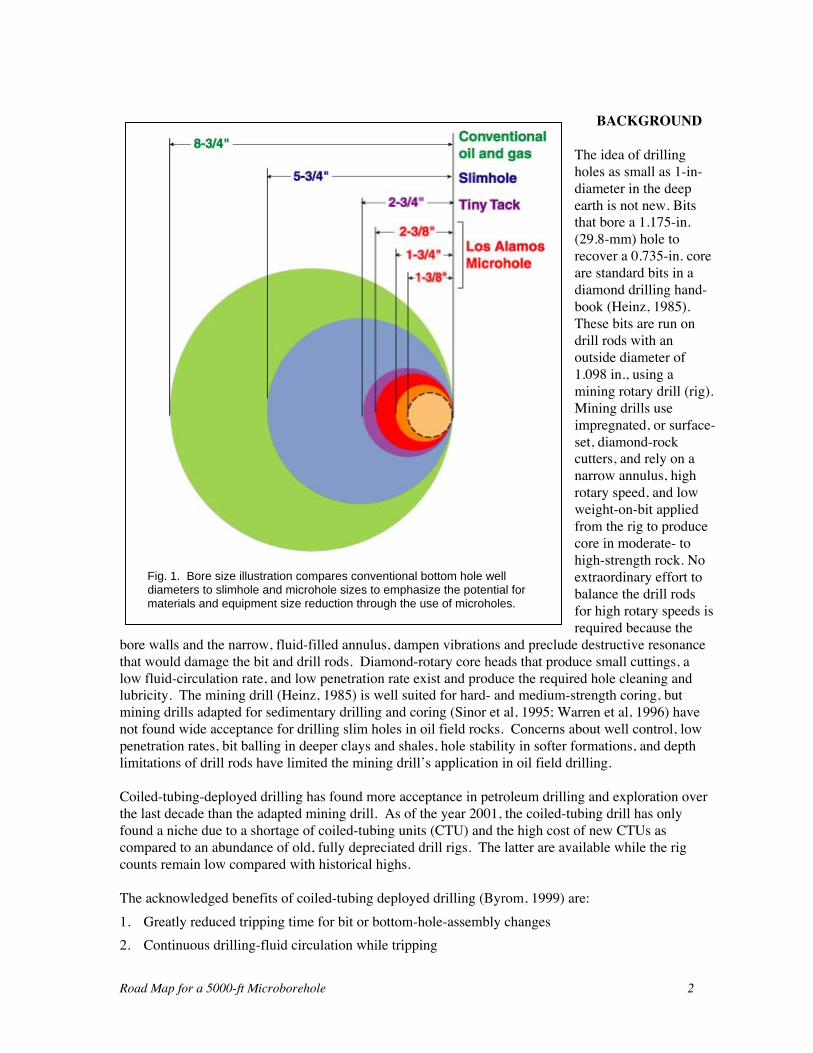
The combination of microdrilling technology and micro-instrumentation provides potentially low-cost, deep wells or through-tubing-produced long laterals for exploration, long-term reservoirmonitoring, and production. Microholes sized to provide access for modern downholeinstrumentation and an assortment of sensors need be no larger than 1-3/8- to 2-in.-diameter atterminal depth. The maximum cost benefit is assumed to occur with the greatest size reduction aslong as the existing drilling and completion equipment infrastructure can be miniaturized using theexisting fabrication methods and does not require the major breakthrough technology. Microholedimensions have a much larger impact on drilling equipment size than slimholes (Fig. 1). Materials,labor, and support equipment to process material and rigup/rigdown the drilling system are greatlyreduced with the proposed microhole infrastructure. A coiled-tubing-deployed, mud-motor-powered,PDC-bit rotary-drilling system (Leising and Newman, 1993) was examined to identify any theoreticalor practical reasons that deep, small-diameter holes cannot be drilled and completed. Some proof-of-concept, laboratory-scale microdrilling demonstrations were conducted to support the investigation(Dreesen and Cohen, 1997). To date, no fundamental limitation on microdrilling to depths in therange of 5000 to 10,000 ft has been identified. This document is the first draft of the Road Map thatdefines the technology development necessary to make microdrilling happen. Drilling programs forshallow- and moderate-depth demonstrations will be developed once the final Road Map is completedand demonstration sites are selected. A full suite of acoustic and electromagnetic sensors and sourcesfor deep investigation, and temperature, pressure, and fluid-property sensors for near wellexamination are either available or can be developed from existing technology. The cost estimatesfor the logging tools in questions are developed in separate reports (Sinclair 2000 and 2001).
Road Map for a 5000-ft Microborehole 2
BACKGROUND
The idea of drillingholes as small as 1-in-diameter in the deepearth is not new. Bitsthat bore a 1.175-in.(29.8-mm) hole torecover a 0.735-in. coreare standard bits in adiamond drilling hand-book (Heinz, 1985).These bits are run ondrill rods with anoutside diameter of1.098 in., using amining rotary drill (rig).Mining drills useimpregnated, or surface-set, diamond-rockcutters, and rely on anarrow annulus, highrotary speed, and lowweight-on-bit appliedfrom the rig to producecore in moderate- tohigh-strength rock. Noextraordinary effort tobalance the drill rodsfor high rotary speeds isrequired because the
bore walls and the narrow, fluid-filled annulus, dampen vibrations and preclude destructive resonancethat would damage the bit and drill rods. Diamond-rotary core heads that produce small cuttings, alow fluid-circulation rate, and low penetration rate exist and produce the required hole cleaning andlubricity. The mining drill (Heinz, 1985) is well suited for hard- and medium-strength coring, butmining drills adapted for sedimentary drilling and coring (Sinor et al, 1995; Warren et al, 1996) havenot found wide acceptance for drilling slim holes in oil field rocks. Concerns about well control, lowpenetration rates, bit balling in deeper clays and shales, hole stability in softer formations, and depthlimitations of drill rods have limited the mining drill’s application in oil field drilling.
Coiled-tubing-deployed drilling has found more acceptance in petroleum drilling and exploration overthe last decade than the adapted mining drill. As of the year 2001, the coiled-tubing drill has onlyfound a niche due to a shortage of coiled-tubing units (CTU) and the high cost of new CTUs ascompared to an abundance of old, fully depreciated drill rigs. The latter are available while the rigcounts remain low compared with historical highs.
The acknowledged benefits of coiled-tubing deployed drilling (Byrom, 1999) are:1. Greatly reduced tripping time for bit or bottom-hole-assembly changes2. Continuous drilling-fluid circulation while tripping
Fig. 1. Bore size illustration compares conventional bottom hole welldiameters to slimhole and microhole sizes to emphasize the potential formaterials and equipment size reduction through the use of microholes.
Road Map for a 5000-ft Microborehole 3
3. Simple, robust, pressure control during drilling4. Suitability for highly automated drilling5. Simple and robust data and control transmission through wirelines installed inside the coiled
tubing6. Low rig-labor requirement compared with conventional tripping7. Reduced rig size, increased portability, and reduced location size requirement
The deficiencies of coiled-tubing deployed drilling (Byrom, 1999) that applied to the microdrillingare:
1. It requires a hydraulic or electric-powered, downhole drilling motor.2. Slide drilling (no capability to rotate drill stem) reduces hole cleaning, increases friction between
bore wall and drill stem, and limits weight-on-bit that can be applied from the surface. This is amajor problem in highly directional and horizontal drilling. It is not a major difficulty in nearvertical drilling or in short directional laterals from adeep, near vertical bore. Very high circulation ratesand short tripping (long cycle reciprocation of the drillstem) improve cuttings transport, but drillingperformance is reduced due to increased time off ofbottom.
3. High circulating pressure and power loss, as comparedwith coupled drill stem, while drilling with a significantamount of tubing on the reel unless the flow rate is lowand differential pressure drop across the bottom-holedrilling assembly (BHDA) is very high. Motors tosupport low-flow, high-differential pressure drilling donot presently exit.
4. There is a lack of backup and redundancy related tostuck pipe, fishing technology, and loss of returnsduring drilling and conventional drilling rigs mustfrequently be deployed to get out of trouble.
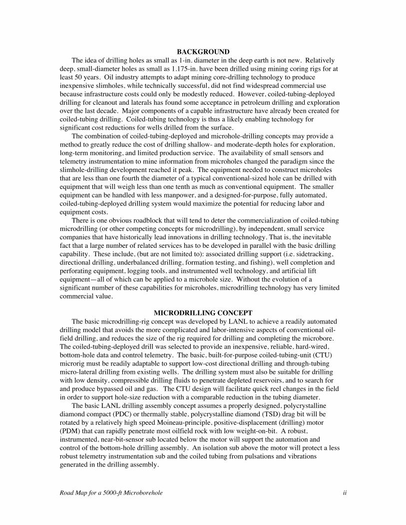
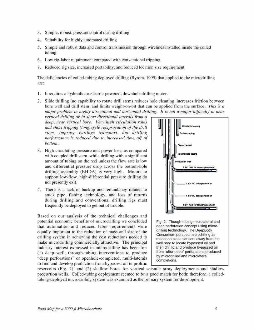
Based on our analysis of the technical challenges andpotential economic benefits of microdrilling we concludedthat automation and reduced labor requirements wereequally important to the reduction of mass and size of thedrilling system in achieving the cost reductions needed tomake microdrilling commercially attractive. The principalindustry interest expressed in microdrilling has been for:(1) deep well, through-tubing interventions to produce“deep perforations” or openhole-completed, multi-lateralsto find and develop production from bypassed oil in prolificreservoirs (Fig. 2), and (2) shallow bores for vertical seismic array deployments and shallowproduction wells. Coiled-tubing deployment seemed to be a good match for both; therefore, a coiled-tubing-deployed microdrilling system was examined as the primary system for development.
Fig. 2. Though-tubing microlateral anddeep perforation concept using micro-drilling technology. The DeepLookConsortium pursued microdrilling asmeans to place sensors away from thewell bore to locate bypassed oil andthen drill to and produce bypassed oilfrom “ultra-deep” perforations producedby microdrilled and microlateralcompletions.
Road Map for a 5000-ft Microborehole 4
INITIAL MICRODRILLING RIG CONCEPT
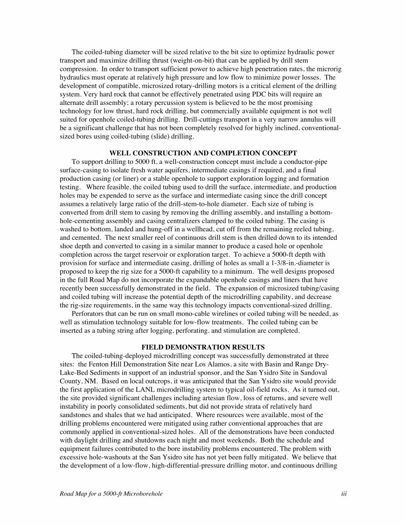
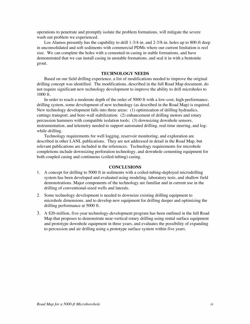
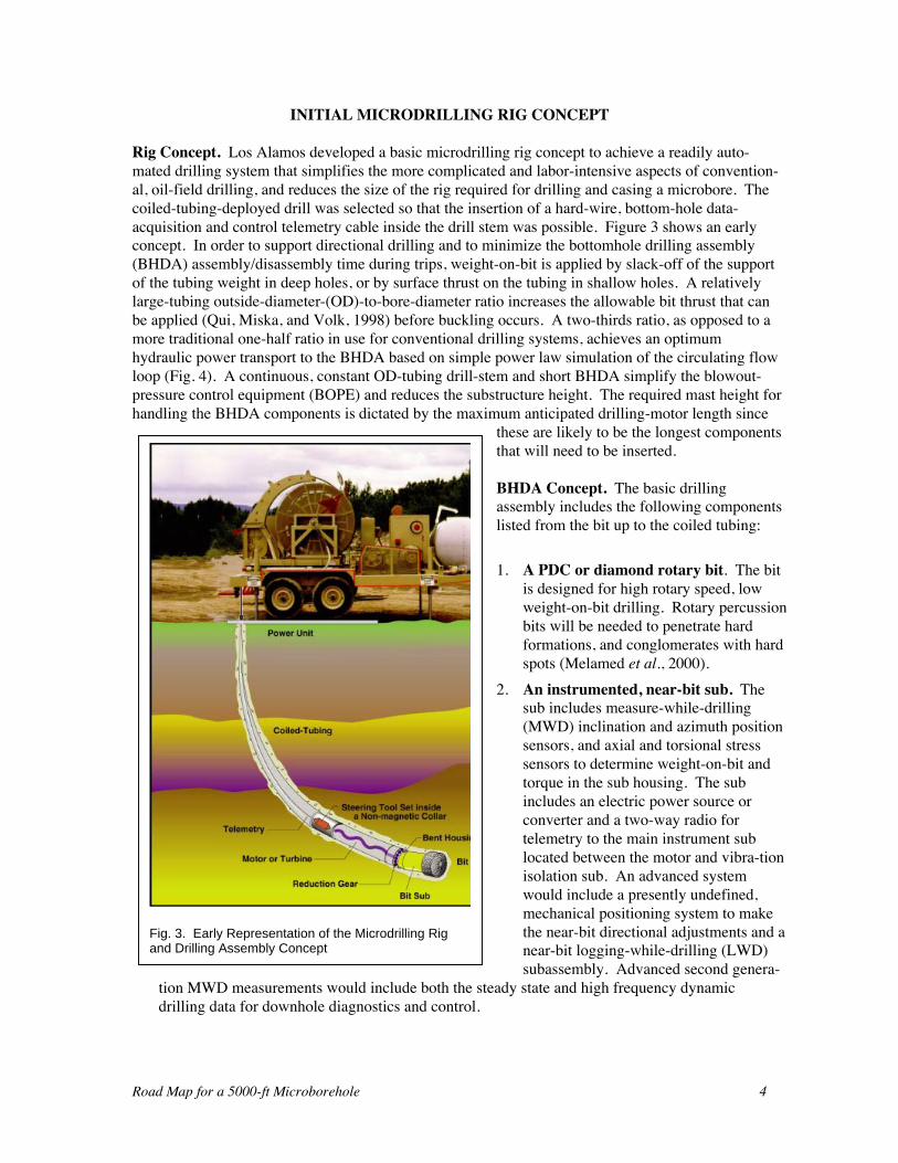
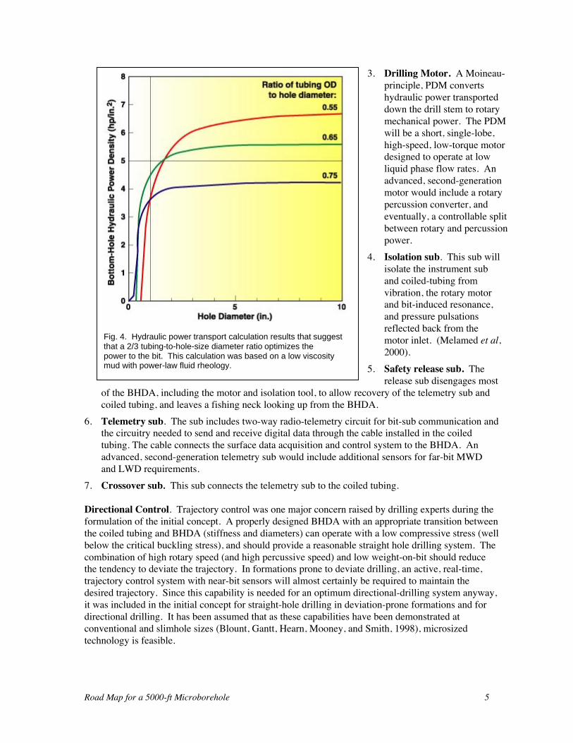
Rig Concept. Los Alamos developed a basic microdrilling rig concept to achieve a readily auto-mated drilling system that simplifies the more complicated and labor-intensive aspects of convention-al, oil-field drilling, and reduces the size of the rig required for drilling and casing a microbore. Thecoiled-tubing-deployed drill was selected so that the insertion of a hard-wire, bottom-hole data-acquisition and control telemetry cable inside the drill stem was possible. Figure 3 shows an earlyconcept. In order to support directional drilling and to minimize the bottomhole drilling assembly(BHDA) assembly/disassembly time during trips, weight-on-bit is applied by slack-off of the supportof the tubing weight in deep holes, or by surface thrust on the tubing in shallow holes. A relativelylarge-tubing outside-diameter-(OD)-to-bore-diameter ratio increases the allowable bit thrust that canbe applied (Qui, Miska, and Volk, 1998) before buckling occurs. A two-thirds ratio, as opposed to amore traditional one-half ratio in use for conventional drilling systems, achieves an optimumhydraulic power transport to the BHDA based on simple power law simulation of the circulating flowloop (Fig. 4). A continuous, constant OD-tubing drill-stem and short BHDA simplify the blowout-pressure control equipment (BOPE) and reduces the substructure height. The required mast height forhandling the BHDA components is dictated by the maximum anticipated drilling-motor length since
these are likely to be the longest componentsthat will need to be inserted.
BHDA Concept. The basic drillingassembly includes the following componentslisted from the bit up to the coiled tubing:
1. A PDC or diamond rotary bit. The bitis designed for high rotary speed, lowweight-on-bit drilling. Rotary percussionbits will be needed to penetrate hardformations, and conglomerates with hardspots (Melamed et al., 2000).
2. An instrumented, near-bit sub. Thesub includes measure-while-drilling(MWD) inclination and azimuth positionsensors, and axial and torsional stresssensors to determine weight-on-bit andtorque in the sub housing. The subincludes an electric power source orconverter and a two-way radio fortelemetry to the main instrument sublocated between the motor and vibra-tionisolation sub. An advanced systemwould include a presently undefined,mechanical positioning system to makethe near-bit directional adjustments and anear-bit logging-while-drilling (LWD)subassembly. Advanced second genera-
tion MWD measurements would include both the steady state and high frequency dynamicdrilling data for downhole diagnostics and control.
Fig. 3. Early Representation of the Microdrilling Rigand Drilling Assembly Concept
Road Map for a 5000-ft Microborehole 5
3. Drilling Motor. A Moineau-principle, PDM convertshydraulic power transporteddown the drill stem to rotarymechanical power. The PDMwill be a short, single-lobe,high-speed, low-torque motordesigned to operate at lowliquid phase flow rates. Anadvanced, second-generationmotor would include a rotarypercussion converter, andeventually, a controllable splitbetween rotary and percussionpower.
4. Isolation sub. This sub willisolate the instrument suband coiled-tubing fromvibration, the rotary motorand bit-induced resonance,and pressure pulsationsreflected back from themotor inlet. (Melamed et al,2000).
5. Safety release sub. Therelease sub disengages most
of the BHDA, including the motor and isolation tool, to allow recovery of the telemetry sub andcoiled tubing, and leaves a fishing neck looking up from the BHDA.
6. Telemetry sub. The sub includes two-way radio-telemetry circuit for bit-sub communication andthe circuitry needed to send and receive digital data through the cable installed in the coiledtubing. The cable connects the surface data acquisition and control system to the BHDA. Anadvanced, second-generation telemetry sub would include additional sensors for far-bit MWDand LWD requirements.
7. Crossover sub. This sub connects the telemetry sub to the coiled tubing.
Directional Control. Trajectory control was one major concern raised by drilling experts during theformulation of the initial concept. A properly designed BHDA with an appropriate transition betweenthe coiled tubing and BHDA (stiffness and diameters) can operate with a low compressive stress (wellbelow the critical buckling stress), and should provide a reasonable straight hole drilling system. Thecombination of high rotary speed (and high percussive speed) and low weight-on-bit should reducethe tendency to deviate the trajectory. In formations prone to deviate drilling, an active, real-time,trajectory control system with near-bit sensors will almost certainly be required to maintain thedesired trajectory. Since this capability is needed for an optimum directional-drilling system anyway,it was included in the initial concept for straight-hole drilling in deviation-prone formations and fordirectional drilling. It has been assumed that as these capabilities have been demonstrated atconventional and slimhole sizes (Blount, Gantt, Hearn, Mooney, and Smith, 1998), microsizedtechnology is feasible.
Fig. 4. Hydraulic power transport calculation results that suggestthat a 2/3 tubing-to-hole-size diameter ratio optimizes thepower to the bit. This calculation was based on a low viscositymud with power-law fluid rheology.
Road Map for a 5000-ft Microborehole 6
Drilling-fluid Circulation. Drilling-fluid circulation serves the same function in the microdrillingconcept as it does in most traditional slide drilling. These include:1. cooling the bit,2. removing cuttings from the hole and cleaning the bit,3. transporting the cuttings up the drill stem/bore annulus to the surface, and4. transporting hydraulic power from the surface to the drilling motor.
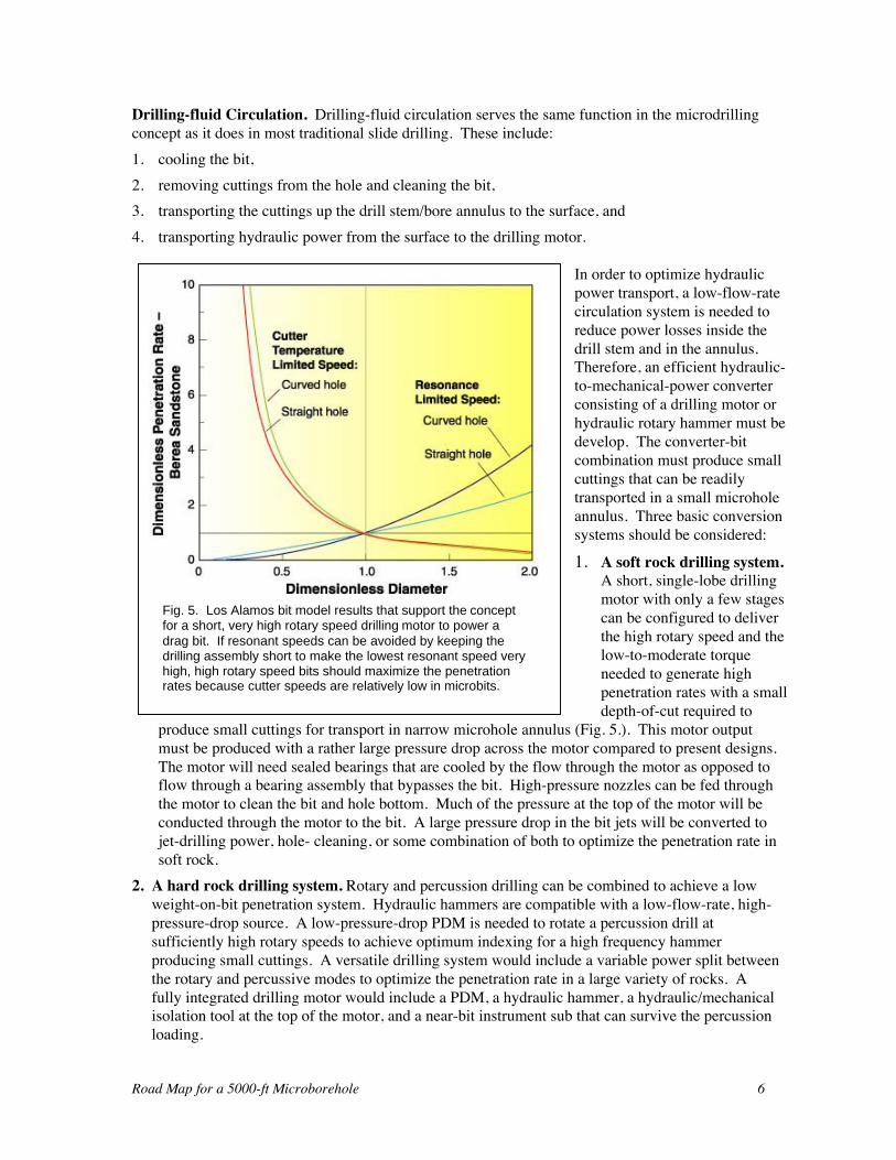
In order to optimize hydraulicpower transport, a low-flow-ratecirculation system is needed toreduce power losses inside thedrill stem and in the annulus.Therefore, an efficient hydraulic-to-mechanical-power converterconsisting of a drilling motor orhydraulic rotary hammer must bedevelop. The converter-bitcombination must produce smallcuttings that can be readilytransported in a small microholeannulus. Three basic conversionsystems should be considered:
1. A soft rock drilling system.A short, single-lobe drillingmotor with only a few stagescan be configured to deliverthe high rotary speed and thelow-to-moderate torqueneeded to generate highpenetration rates with a smalldepth-of-cut required to
produce small cuttings for transport in narrow microhole annulus (Fig. 5.). This motor outputmust be produced with a rather large pressure drop across the motor compared to present designs.The motor will need sealed bearings that are cooled by the flow through the motor as opposed toflow through a bearing assembly that bypasses the bit. High-pressure nozzles can be fed throughthe motor to clean the bit and hole bottom. Much of the pressure at the top of the motor will beconducted through the motor to the bit. A large pressure drop in the bit jets will be converted tojet-drilling power, hole- cleaning, or some combination of both to optimize the penetration rate insoft rock.
2. A hard rock drilling system. Rotary and percussion drilling can be combined to achieve a lowweight-on-bit penetration system. Hydraulic hammers are compatible with a low-flow-rate, high-pressure-drop source. A low-pressure-drop PDM is needed to rotate a percussion drill atsufficiently high rotary speeds to achieve optimum indexing for a high frequency hammerproducing small cuttings. A versatile drilling system would include a variable power split betweenthe rotary and percussive modes to optimize the penetration rate in a large variety of rocks. Afully integrated drilling motor would include a PDM, a hydraulic hammer, a hydraulic/mechanicalisolation tool at the top of the motor, and a near-bit instrument sub that can survive the percussionloading.
Fig. 5. Los Alamos bit model results that support the conceptfor a short, very high rotary speed drilling motor to power adrag bit. If resonant speeds can be avoided by keeping thedrilling assembly short to make the lowest resonant speed veryhigh, high rotary speed bits should maximize the penetrationrates because cutter speeds are relatively low in microbits.
Road Map for a 5000-ft Microborehole 7
3. An efficient downhole motor powered with compressible drilling fluids. An efficientdownhole motor powered with compressible drilling fluids is needed to drill under-pressuredformations and depleted reservoirs that experience high drilling-fluid losses when drilled withtraditional water-based mud (Graham, 1995). Both rotary and rotary-percussion systems need tobe adapted to operate efficiently with compressible drilling fluids. It is anticipated thatconventional approaches to drilling motors for compressible fluids will produce very poorconversion efficiencies. This technology development will require a novel approach for itssolution.
For all of these systems, the flow rate will have to be high enough to keep the cuttings concentrationat any point in the annulus well below 5% by volume at the maximum desired penetration rate. Highconcentrations will result in excessive pressure losses due to particle interactions. Determining theoptimum circulation rate to produce the optimum penetration rate is a complex, non-linearoptimization problem that will require acomputationally sophisticated systems analysis.
WELL CONSTRUCTION ANDCOMPLETION
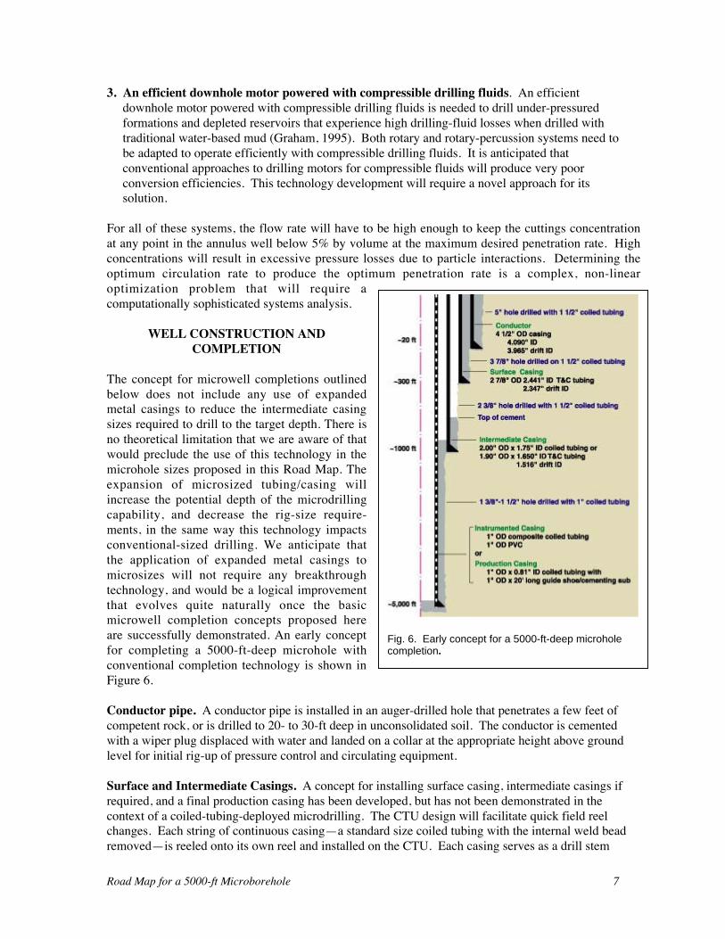
The concept for microwell completions outlinedbelow does not include any use of expandedmetal casings to reduce the intermediate casingsizes required to drill to the target depth. There isno theoretical limitation that we are aware of thatwould preclude the use of this technology in themicrohole sizes proposed in this Road Map. Theexpansion of microsized tubing/casing willincrease the potential depth of the microdrillingcapability, and decrease the rig-size require-ments, in the same way this technology impactsconventional-sized drilling. We anticipate thatthe application of expanded metal casings tomicrosizes will not require any breakthroughtechnology, and would be a logical improvementthat evolves quite naturally once the basicmicrowell completion concepts proposed hereare successfully demonstrated. An early conceptfor completing a 5000-ft-deep microhole withconventional completion technology is shown inFigure 6.
Conductor pipe. A conductor pipe is installed in an auger-drilled hole that penetrates a few feet ofcompetent rock, or is drilled to 20- to 30-ft deep in unconsolidated soil. The conductor is cementedwith a wiper plug displaced with water and landed on a collar at the appropriate height above groundlevel for initial rig-up of pressure control and circulating equipment.
Surface and Intermediate Casings. A concept for installing surface casing, intermediate casings ifrequired, and a final production casing has been developed, but has not been demonstrated in thecontext of a coiled-tubing-deployed microdrilling. The CTU design will facilitate quick field reelchanges. Each string of continuous casing—a standard size coiled tubing with the internal weld beadremoved—is reeled onto its own reel and installed on the CTU. Each casing serves as a drill stem
Fig. 6. Early concept for a 5000-ft-deep microholecompletion.
Road Map for a 5000-ft Microborehole 8
before it is installed as a casing. After the casing/drill stem is drilled down to the shoe depth, theBHDA is tripped out, the telemetry cable is removed from the coiled tubing, and a bottom-hole-cementing-assembly (BHCA) is installed. The BHCA includes: a washing/spudding shoe, a floatvalve, landing joint(s), a wiper plug catcher, and a crossover to connect to the continuous casing. Asthe casing is inserted, fluted casing centralizers are clamped on to center the casing in the annulus.The casing is washed to bottom, landed and hung-off in a wellhead, and cut off from the remainingreeled casing. A cementing head is installed on the wellhead, and the hole is circulated to conditionthe mud for cementing. A standard cement job is performed and displaced with a wiper plug andwater. While the cement sets up, the reel is replaced with the reel of the next smaller diameter drillstem/casing, and a BHDA is installed on the bottom end of the tubing to drill out the wiper plug andthe cemented casing BHCA. The next smaller casing is then drilled down to its intended shoe depthand it is installed in a similar manner.
Production Tubing. Cased hole or openhole completions are both feasible as long as the smallestcoiled tubing and its BHDA will fit inside the production casing. Long term monitoring can beconducted from wirelines or coiled-tubing-deployed instruments that are installed or inserted andretrieved on a schedule. Mechanical perforators, abrasive jet perforators, or perforators can bedownsized and run on small, mono-cable wirelines or the coiled tubing to support sampling ofproduction from cased holes. The coiled tubing can be inserted as a tubing string after stimulation if atubingless completion is not feasible.
Stimulation. Reservoir sampling or production wells may need to be stimulated. For now, it hasbeen assumed that most stimulation methods will be feasible in microholes. Clearly there will bemajor challenges learning how to adapt stimulation technology for microsized holes and thistechnology will have to be developed and evaluated.
INDUSTRY INPUT TO THE INITIAL CONCEPT
Industry Contractors and Collaborators. Two contractors have participated in the development ofthe initial microdrilling concept:
1. Maurer Technology. Under contract to Los Alamos National Laboratory, Maurer Technologyconducted early drilling laboratory testing of 1-1/2-in. and 1-11/16 in. OD drilling motors, a 54-mm hydraulic hammer, and 1-3/4-in., 46-mm, and 59-mm bits (Dreesen and Cohen, 1997). Theproof-of-concept testing program produced: (1) a database on penetration rate versus weight-on-bit and rotary speed for various bits and rocks, (2) motor performance data for the smallestcommercial drilling motors then available, and (3) limited drilling performance data for thePDMs and a hydraulic hammer in Berea Sandstone, Carthage Marble (Limestone), and SierraWhite Granite. Maurer Technology also developed some concepts for a downhole sub-component that would regulate the weight-on-bit.
2. Coiled Tubing Engineering Services, L. C. (CTES, L.C.). Under contract to Los AlamosNational Laboratory, CTES ran their coiled-tubing forces and fatigue models to (1) calculate theweight-on-bit that could be applied with surface thrusting for various trajectories, and (2) predictthe tubing life under the simulated drilling conditions (CTES, L. C, 1996.). CTES also developeda conceptual design for a coiled-tubing-deployed microdrilling platform. Their concept includedan elevated reel that eliminated the gooseneck on the CTU and thus reduced the fatigue cycles toone-third the number of cycles that occur using a gooseneck.
3. Fleet Cementers (formally a subsidiary of Plains Energy Services Ltd. of Calgary, AlbertaCanada and subsequent to our interaction a subsidiary of Precision Drilling Corporation). Tom
Road Map for a 5000-ft Microborehole 9
Gipson, President of Fleet Cementers, reviewed and critiqued the microdrilling concept andshared some of Fleet’s experience with coiled-tubing-deployed drilling of conventional-sized andslimhole bores. Their experience supports our expectation that drilling with short drillingassemblies and coiled-tubing thrust on the drilling assembly would preclude the need for drillcollars.
Industry Feedback. Early variations of the initial microhole-drilling concept were presented tomany oil and service company representatives, and industry consortia. Concerns expressed abouttechnical and practical aspects of this approach focused on three aspects of the concept:1. Market for microholes. Several industry representatives have indicated that they find the
microborehole technically plausible but do not believe that the concept is marketable to thedrilling industry. They see a chicken and egg problem that will result in a repeat of the slimholeexperience, which has limited slimhole drilling to a small niche of the total oil field drillingbusiness. They cannot see microboreholes as being even a very small niche of the slimholedrilling business. Typically, they cannot imagine a cost savings sufficient to drive the nearsimultaneous development of the infrastructure required to make microboreholes an attractivealternative to conventional holes.
2. Drilling performance. Our economic justification for the microborehole concept has focused ontwo major benefits: (1) Reduced mass of the system components that reduces the materialsrequired by an order of magnitude and fabrication and mobilization costs by a lesser factor. (2)Reduced labor costs because everything that can be automated will be; the handling of smallcomponents will not require more than two people when operations are not readily automated.Some in industry do not seem to place as much value on these cost benefits as we do; mostindustry input emphasizes high drilling rate as a critical aspect of the microdrilling concept.Without an advanced drilling concept based on an entirely new, or at least different drillingprocess, we do not believe that a substantial increase in drill rate over representative conventionalrates is feasible for deep microdrilling. Just achieving a customary drill rate using a hydraulic-powered drill presents a major challenge for the following reasons:(a) As the annular gap between the drill stem and bore is decreased, the maximum allowable
drill-cutting particle-size must be decreased proportionally. Therefore, the specific energy tofragment a formation is greater, which increases the hydraulic power that must be transportedto the drill motor.
(b) Flow rates in the annulus must be kept low to assure that pressure losses in the annulus arenot excessive (e.g., exceed the allowable maximum circulation density). The volumetriccuttings concentration must be kept well below 5% to maintain a continuous liquid phase andavoid the high pressure loss that occurs when solid particle interactions start to influenceannular flow behavior. The combination of low annular flow rates, high penetration rates,and low annular particle concentrations produces a contradiction.
3. Annular flow. Our initial hydraulic power transport calculations assumed a power-law fluid andignored the effect of cuttings transport. Several drilling experts have warned that the frictionpressure drop in the annulus will exceed the pressure calculated with simulators even aftercuttings transport is included in the model. They are concerned that the equivalent circulatingdensity during drilling will lead to well control problems during tripping, and will cause severeloss circulation problems in normally pressured formations.
Road Map for a 5000-ft Microborehole 10
FIELD DEMONSTRATIONS RESULTS
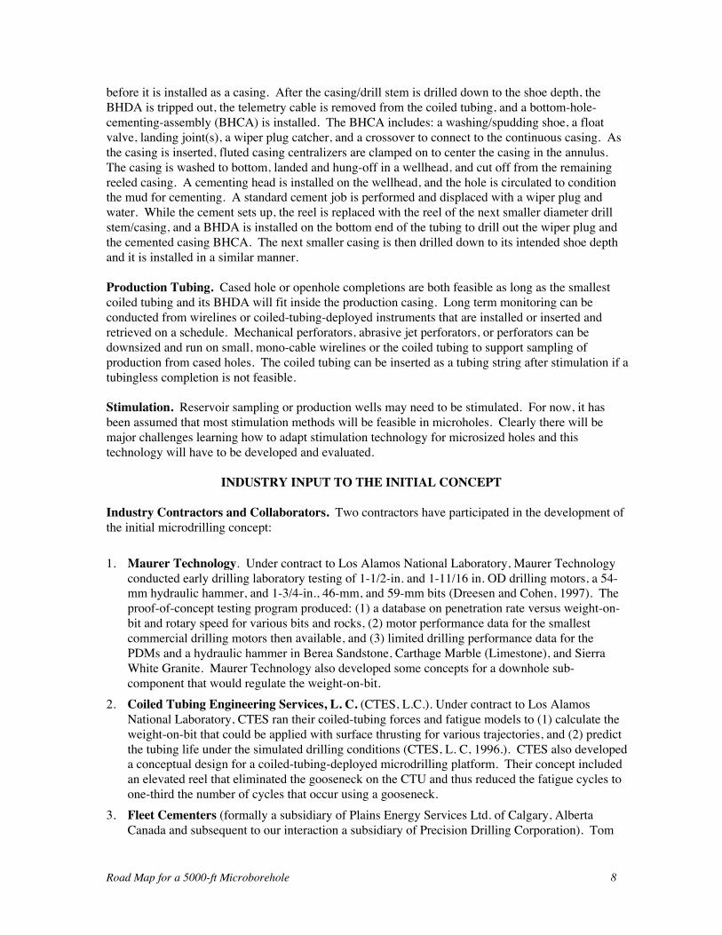
Coiled-tubing deployed microdrill field demonstrations have been conducted at three sites. All of thedemonstrations have been conducted with a single daylight drilling tour and long shutdowns eachnight and most weekends. The selection of bits and bit motor combinations for the formations thatwere encountered should not be considered as optimal. Typical bottom-hole-assemblies included:1. A drag bit. Figure 7 shows four bits that were used in the early field demonstrations.2. A bit sub if needed.3. PDM runs which included 1-1/2 in. OD, single-lobe and 1-11/16 in. 5:6 multi-lobe motors.4. A double ball check.5. A mechanical/ hydraulic release sub set to shear at 4000 to 6000 lbf.6. A coiled-tubing connector with a slip-grab.7. A 1-in. OD, 0.087-in. wall, 0.826-in. ID, 0.810 lbm/ft, Grade 70 or 1-in. OD, 0.095-in. wall,
0.810-in. ID, 0.918 lb/ft, Grade 70 coiled tubing.
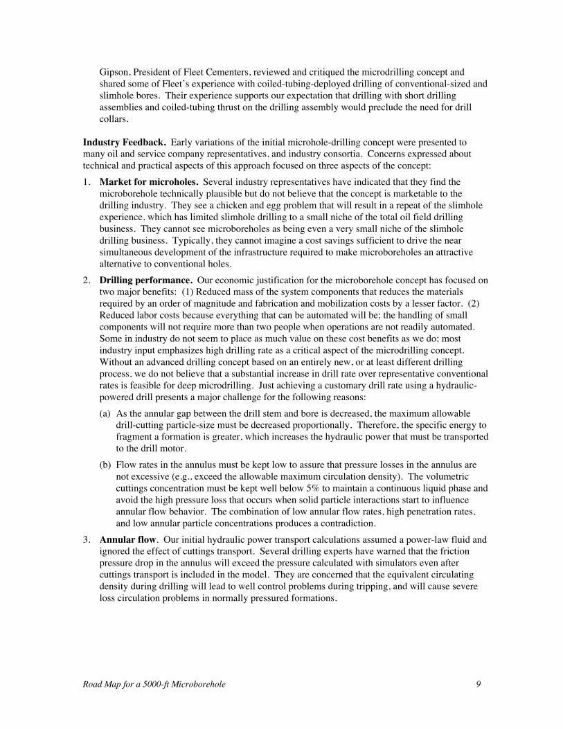
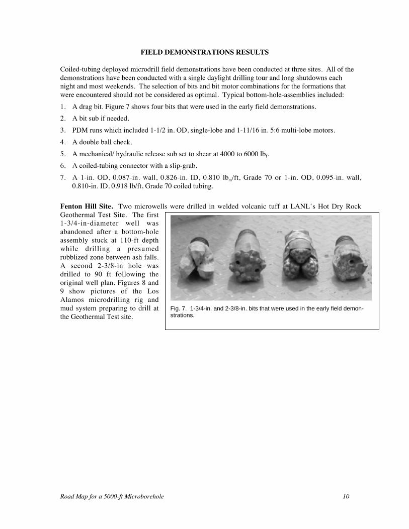
Fenton Hill Site. Two microwells were drilled in welded volcanic tuff at LANL’s Hot Dry RockGeothermal Test Site. The first1-3/4-in-diameter well wasabandoned after a bottom-holeassembly stuck at 110-ft depthwhile drilling a presumedrubblized zone between ash falls.A second 2-3/8-in hole wasdrilled to 90 ft following theoriginal well plan. Figures 8 and9 show pictures of the LosAlamos microdrilling rig andmud system preparing to drill atthe Geothermal Test site.
Fig. 7. 1-3/4-in. and 2-3/8-in. bits that were used in the early field demon-strations.
Road Map for a 5000-ft Microborehole 11
Fig. 9. The Los Alamos mud cleaning system includes a shale shaker, settling tank, andhydrocyclone mud cleaners. The cleaner was manufactured by TriFlo to meet the needs of thetrenchless utilities industry It has been upgraded by Los Alamos to improve the performance of thecleaning unit to reduce mud-pump wear.
Fig. 8. The Los Alamos coiled-tubing microdrilling rig, (center front), with the mud cleaning system(far left), and the logging van which houses the data acquisition system (far right).
Road Map for a 5000-ft Microborehole 12
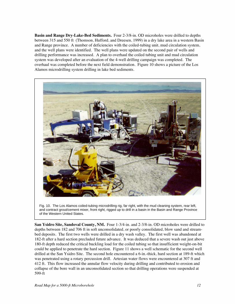
Basin and Range Dry-Lake-Bed Sediments. Four 2-3/8-in. OD microholes were drilled to depthsbetween 315 and 550 ft (Thomson, Hufford, and Dreesen, 1999) in a dry lake area in a western Basinand Range province. A number of deficiencies with the coiled-tubing unit, mud circulation system,and the well plans were identified. The well plans were updated on the second pair of wells anddrilling performance was increased. A plan to overhaul the coiled tubing unit and mud circulationsystem was developed after an evaluation of the 4-well drilling campaign was completed. Theoverhaul was completed before the next field demonstration. Figure 10 shows a picture of the LosAlamos microdrilling system drilling in lake bed sediments.
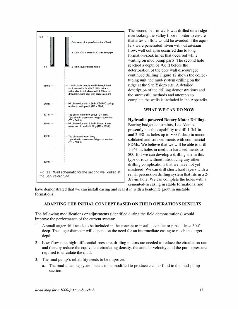
San Ysidro Site, Sandoval County, NM. Four 1-3/4-in. and 2-3/8-in. OD microholes were drilled todepths between 182 and 706 ft in soft unconsolidated, or poorly consolidated, blow sand and stream-bed deposits. The first two wells were drilled in a dry wash valley. The first well was abandoned at182-ft after a hard section precluded future advance. It was deduced that a severe wash out just above180-ft depth reduced the critical buckling load for the coiled tubing so that insufficient weight-on-bitcould be applied to penetrate the hard section. Figure 11 shows a well schematic for the second welldrilled at the San Ysidro Site. The second hole encountered a 6-in.-thick, hard section at 189-ft whichwas penetrated using a rotary percussion drill. Artesian water flows were encountered at 307 ft and412 ft. This flow increased the annular flow velocity during drilling and contributed to erosion andcollapse of the bore wall in an unconsolidated section so that drilling operations were suspended at599-ft
Fig. 10. The Los Alamos coiled-tubing microdrilling rig, far right, with the mud cleaning system, rear left,and contract grout/cement mixer, front right, rigged up to drill in a basin in the Basin and Range Provinceof the Western United States.
Road Map for a 5000-ft Microborehole 13
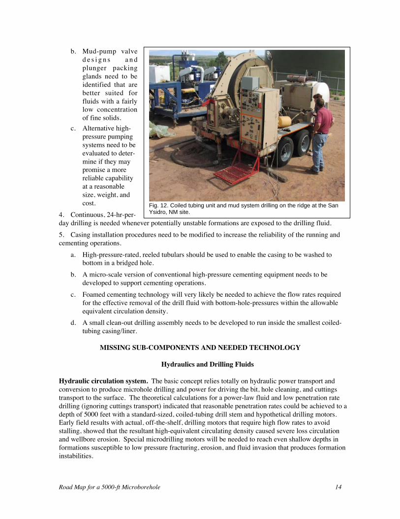
The second pair of wells was drilled on a ridgeoverlooking the valley floor in order to ensurethat artesian flow would be avoided if the aqui-fers were penetrated. Even without artesianflow, well collapse occurred due to longformation-soak times that occurred whilewaiting on mud pump parts. The second holereached a depth of 706 ft before thedeterioration of the bore wall discouragedcontinued drilling. Figure 12 shows the coiled-tubing unit and mud-system drilling on theridge at the San Ysidro site. A detaileddescription of the drilling demonstrations andthe successful methods and attempts tocomplete the wells is included in the Appendix.
WHAT WE CAN DO NOW
Hydraulic-powered Rotary Motor Drilling.Barring budget constraints, Los Alamospresently has the capability to drill 1-3/4-in.and 2-3/8-in. holes up to 800-ft deep in uncon-solidated and soft sediments with commercialPDMs. We believe that we will be able to drill1-3/4-in. holes in medium-hard sediments to800-ft if we can develop a drilling site in thistype of rock without introducing any otherdrilling complications that we have not yetmastered. We can drill short, hard layers with arental percussion drilling system that fits in a 2-3/8-in. hole. We can complete the holes with acemented-in casing in stable formations, and
have demonstrated that we can install casing and seal it in with a bentonite grout in unstableformations.
ADAPTING THE INITIAL CONCEPT BASED ON FIELD OPERATIONS RESULTS
The following modifications or adjustments (identified during the field demonstrations) wouldimprove the performance of the current system:1. A small auger drill needs to be included in the concept to install a conductor pipe at least 30-ft
deep. The auger diameter will depend on the need for an intermediate casing to reach the targetdepth.
2. Low-flow-rate, high-differential-pressure, drilling motors are needed to reduce the circulation rateand thereby reduce the equivalent circulating density, the annular velocity, and the pump pressurerequired to circulate the mud.
3. The mud pump’s reliability needs to be improved.a. The mud-cleaning system needs to be modified to produce cleaner fluid to the mud-pump
suction.
Fig. 11. Well schematic for the second well drilled atthe San Ysidro Site.
Road Map for a 5000-ft Microborehole 14
b. Mud-pump valved e s i g n s a n dplunger packingglands need to beidentified that arebetter suited forfluids with a fairlylow concentrationof fine solids.
c. Alternative high-pressure pumpingsystems need to beevaluated to deter-mine if they maypromise a morereliable capabilityat a reasonablesize, weight, andcost.
4. Continuous, 24-hr-per-day drilling is needed whenever potentially unstable formations are exposed to the drilling fluid.5. Casing installation procedures need to be modified to increase the reliability of the running andcementing operations.
a. High-pressure-rated, reeled tubulars should be used to enable the casing to be washed tobottom in a bridged hole.
b. A micro-scale version of conventional high-pressure cementing equipment needs to bedeveloped to support cementing operations.
c. Foamed cementing technology will very likely be needed to achieve the flow rates requiredfor the effective removal of the drill fluid with bottom-hole-pressures within the allowableequivalent circulation density.
d. A small clean-out drilling assembly needs to be developed to run inside the smallest coiled-tubing casing/liner.
MISSING SUB-COMPONENTS AND NEEDED TECHNOLOGY
Hydraulics and Drilling Fluids
Hydraulic circulation system. The basic concept relies totally on hydraulic power transport andconversion to produce microhole drilling and power for driving the bit, hole cleaning, and cuttingstransport to the surface. The theoretical calculations for a power-law fluid and low penetration ratedrilling (ignoring cuttings transport) indicated that reasonable penetration rates could be achieved to adepth of 5000 feet with a standard-sized, coiled-tubing drill stem and hypothetical drilling motors.Early field results with actual, off-the-shelf, drilling motors that require high flow rates to avoidstalling, showed that the resultant high-equivalent circulating density caused severe loss circulationand wellbore erosion. Special microdrilling motors will be needed to reach even shallow depths informations susceptible to low pressure fracturing, erosion, and fluid invasion that produces formationinstabilities.
Fig. 12. Coiled tubing unit and mud system drilling on the ridge at the SanYsidro, NM site.
Road Map for a 5000-ft Microborehole 15
Hydraulic converter technology. Small PDMs were not developed for openhole drilling; they areused primarily for scale removal and drill out of cement inside tubing. Off-the-shelf motors aredesigned to operate at high flow rates and standard differential pressure. They typically operateinside tubing and small liners where the high annular velocities needed to produce the requiredpumping power require high pressure pumps, but are otherwise harmless. Small motor designs arepresently constrained by the industry’s limited ability to fabricate small stators and rotors. Stators aremanufactured using injection-molding methods that have evolved to fabricate much larger stators.Injection molding is not well-suited to production of small stators. The machine tools used tofabricate rotors are also optimized for larger rotors and are marginal when used for the smallestdiameter rotors. The dimensional tolerances between the stators and rotors for the small motors areassumed to be of the same order as they are in conventional-sized motors. Therefore, interferencebetween the rotor and the stator is significantly more variable in a small motor, and the conversionefficiency and performance of a small motor is therefore also highly variable. A large interferenceconverts too much hydraulic power to heat in the stator, and a small interference allows too muchfluid to leak across the rotor-stator seals, reducing both the pressure drop available for powerconversion and the volumetric efficiency of the motor. Because the present market for small motorsis very small, there is little incentive for the industry to increase the variety and quality of the smallmotors. There is even less interest in producing the even smaller motors that will be needed to drilland complete a 1-3/8-in. hole for which there is presently no market.
There are no small PDMs presently designed to operate at low-flow and high-differential pressure.The major technical barrier to the development of micro PDM motors is the fabrication of the rotorsand stators. Methods to produce long, small-diameter rotors and stators have been proposed over theyears, but it will take a significant investment to evaluate the various methods and demonstratefeasibility.
Hydraulic hammers are far less technically advanced than PDMs. The hammer that was tested in thelaboratory (Melamed et al., 2000) was unable to produce penetration rates as high as a rotary drill, butprobably would out-perform pure rotary drilling in hard rock in a shallow field demonstration on aneconomic basis, if not on a penetration rate basis. While prototype isolation tools have been designedand tested, there is no accepted performance specification established that assures that the drillingassembly will be protected. Consequently, no equipment is presently available that can be used withany assurance that it will provide the protection needed. Effective isolation tools will be requiredbefore rotary percussion drilling can be combined with downhole sensors and controllersubassemblies
Hydraulic modeling capability. For microdrilling to reach 5000-ft depth, the hydraulic system mustbe optimized. Accurate simulation provides the most efficient means to achieve a first cut atoptimization. Further optimization will require deep demonstrations with realistic flow geometry anddrilling fluids. Relying on a field demonstration system to guide the initial attempt to optimizeperformance is very inefficient because of the large number of potentially controllable variables. Thisincludes: fluid properties, coiled tubing-to-hole-size ratios, depths, penetration rates, and drillcuttings-size distributions that must all be varied in a realistic optimization process.
Published flow versus pressure-drop models start with Newtonian laminar and turbulent pipe flow,and introduce corrections for non-Newtonian fluids, annular flow, eccentricity, skew, and drill cuttingconcentration and transport. Each correction introduces small errors to the calculated result so largeerrors cannot be ruled out in predications of annular flow where all of these corrections must beapplied. Industry drilling experts have repeatedly warned us that annular pressure losses will exceedcalculated losses, and our limited field experience supports that. More accurate models are needed to
Road Map for a 5000-ft Microborehole 16
support the process optimization that will be required. Optimization of rheological parameters andthe annular gap to support drilling over a large range of depths, penetration rates, and cutting sizedistributions will be required.
Mud Pumps. High-pressure drilling fluid pumps are almost always a weak link in the oil fielddrilling system. They require more maintenance and are subject to significantly more unpredictablefailures and down time than most other components in a drilling system. The mud pump failuresobserved in our limited field operations indicate that this will also be true for microsized pumps, andin fact, the small pumps may be more prone to excessive abrasive wear and catastrophic failures thanfull-sized pumps. The normal tactic to address mud-pump reliability is to have redundant pumps, alarge inventory of spare parts on the rig, and sufficient manpower that can be quickly mobilized tooverhaul pumps in the field. While this approach is very likely a possible solution for microsizedpumps, it is not consistent with a highly mobile system because of:1. The extra equipment necessary to provide redundancy and the manifolding required,2. The adverse impact on automation and control requirements caused by the more complex system
with higher level diagnostics and trouble shooting, and3. The extra manpower to service, maintain, and repair pumps in the field.Conventional mud pumps are triplex plunger or piston pumps. Many alternative pumping systemshave been evaluated but none has found a commercial role on drill rigs. There are several alternative-pumping systems feasible in a small pump configuration, that have not proved to be practical in largesizes. These include the following concept pumps:1. A throwaway version of the centrifugal horizontal pump. This is a submersible pump that has
been adapted to high-pressure water injection service. Downhole submersible pumps have beenmodified to improve their performance in pumping fluids which have some solids in them. Whenmanufactured in large quantities the cost of these pumps is relatively low when compared to otherhigh-pressure pumps. If these pumps can be easily inserted and removed from the pumping-system and their life can be accurately forecast while pumping drilling fluids, then their use maybe feasible.
2. A pressure multiplier (intensifier) pump. This is a positive displacement pump that usesrelatively large, hydraulic-powered, reciprocating plungers to convert high-flow-rate, low-pressure, clean fluid, hydraulic power to a low-rate, high-pressure, slurry power. They have beenused successfully for very high-pressure, high-sand-concentration, hydraulic-fracturingtreatments. They require a lot of extra equipment, piping and operational complexity, which hasnot proven to be justified for traditional, high-pressure drilling pumps. In a microsized pumpingsystem, the extra weight and complexity may be quite realistic if the power fluid can be commonwith the fluid needed to power the CTU.
3. A barrier type trash pump. These pumps isolate the plunger packing from the slurry with aflexible, low-pressure, highly elastic barrier to separate the working fluid from the fluid aroundthe plunger packing. Unfortunately, these pumps do not address the abrasive wear on the pumpvalves which is often a more difficult problem than the plunger packing wear.
At this point this list is not complete, and other pumps should be considered before a technologyselection for a short list of micropump concepts for evaluation is selected.
Drilling fluid cleaning. Regardless of the high-pressure mud pump that is selected, providing thecleanest fluid possible to the pump suction will greatly reduce the effective pumping cost. All high-pressure pumps are vulnerable to accelerated wear when pumping abrasive fluids. Any significant
Road Map for a 5000-ft Microborehole 17
reduction in the fine abrasive content of a fluid will be rewarded with reduced pump maintenance andrepairs.
A low-flow-rate, mud-cleaning system is needed that cleans the mud at least as well as the besttechnology available for full-sized mud systems, and that removes fine abrasives if this can be donewith a compact, readily automated system. Based on a brief review of present mud-cleaningtechnology and our experience with an off-the-shelf cleaning system, we believe that a three-stagehydrocyclone and shaker system will be sufficient. It may be possible to use horizontal separatortechnology to reduce the quantity of fluid that has to be processed through the first, large particleremoval stage. Shaker screens are a weak link in the present technology, and they may have to bereplaced or augmented with small settling tanks and sump pumps to recover screen overflow.
Downhole Drilling Sensors and Controls
Weight-on-bit and torque sensors. The capability to make accurate, real-time, bottomholemeasurements of weight-on-bit and torque is a critical element of a deep, coiled-tubing-deployeddrilling system. Slide drilling inherently generates greater friction between the drill stem and borewall than rotating drilling, and therefore, surface measurements of drill stem tension and torsion arenot a good indication of drilling condition in deep holes.
The best indication of bottomhole drilling conditions would be a continuous measurement of torsionand compression stress in the bit sub. The sensors should provide a steady-state average for basicdrill process control and high-data-rate amplitude data for dynamic analysis for advanced drillingprocess control and bit damage prevention. Measurements above the downhole motor are easier tosupport than bit-sub measurements, and may be adequate for microrotary-drilling systems in soft-to-medium strength rock. Hard rock and rotary percussion drilling and instrument-protection isolationcapability will require near-bit sensors to achieve practical downhole control.
Downhole weight-on-bit and torque control. An ideal weight-on-bit control system would providepositioning information to the surface so that drill stem can be inserted as hole is produced andgenerate a downhole compression stress in a variable length housing as close to the bit as feasible. Adownhole torsion control loop will need to generate the torsion in the downhole motor with a rotaryspeed controller. Selection of the steady-state target output values for weight-on-bit and torsion willbe generated manually at the surface by the driller or by automated drilling-control system. A controlsystem would evaluate the downhole, steady-state, sensor data (and dynamic near-bit and downholesensor data, if available in real time) and automatically develop a drilling rate and bit life optimizationtradeoff strategy.
Road Map for a 5000-ft Microborehole 18
Downhole Trajectory Sensors and Directional Drilling Controls
Inclination and Azimuth Sensors. Accurate, real-time, bottomhole measurement of inclination andazimuth will be needed to feed an active directional control system. Bit sub sensors are critical fortimely input to the trajectory control system.
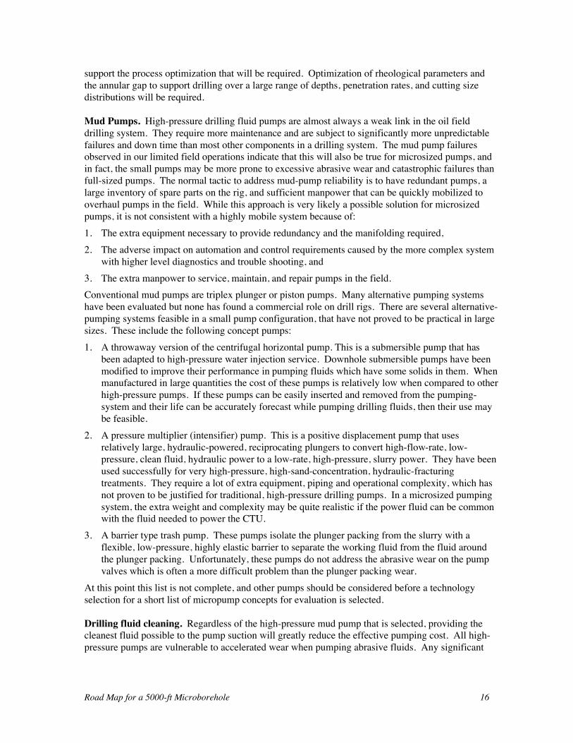
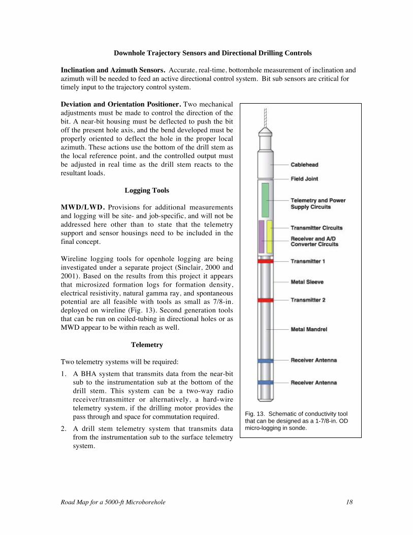
Deviation and Orientation Positioner. Two mechanicaladjustments must be made to control the direction of thebit. A near-bit housing must be deflected to push the bitoff the present hole axis, and the bend developed must beproperly oriented to deflect the hole in the proper localazimuth. These actions use the bottom of the drill stem asthe local reference point, and the controlled output mustbe adjusted in real time as the drill stem reacts to theresultant loads.
Logging Tools
MWD/LWD. Provisions for additional measurementsand logging will be site- and job-specific, and will not beaddressed here other than to state that the telemetrysupport and sensor housings need to be included in thefinal concept.
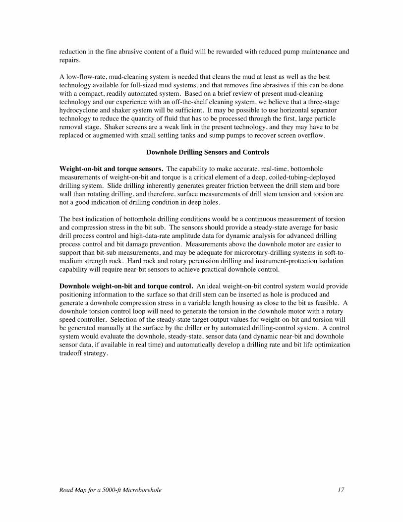
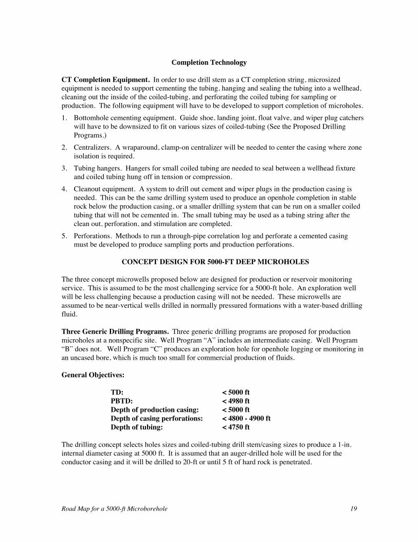
Wireline logging tools for openhole logging are beinginvestigated under a separate project (Sinclair, 2000 and2001). Based on the results from this project it appearsthat microsized formation logs for formation density,electrical resistivity, natural gamma ray, and spontaneouspotential are all feasible with tools as small as 7/8-in.deployed on wireline (Fig. 13). Second generation toolsthat can be run on coiled-tubing in directional holes or asMWD appear to be within reach as well.
Telemetry
Two telemetry systems will be required:1. A BHA system that transmits data from the near-bit
sub to the instrumentation sub at the bottom of thedrill stem. This system can be a two-way radioreceiver/transmitter or alternatively, a hard-wiretelemetry system, if the drilling motor provides thepass through and space for commutation required.
2. A drill stem telemetry system that transmits datafrom the instrumentation sub to the surface telemetrysystem.
Fig. 13. Schematic of conductivity toolthat can be designed as a 1-7/8-in. ODmicro-logging in sonde.
Road Map for a 5000-ft Microborehole 19
Completion Technology
CT Completion Equipment. In order to use drill stem as a CT completion string, microsizedequipment is needed to support cementing the tubing, hanging and sealing the tubing into a wellhead,cleaning out the inside of the coiled-tubing, and perforating the coiled tubing for sampling orproduction. The following equipment will have to be developed to support completion of microholes.1. Bottomhole cementing equipment. Guide shoe, landing joint, float valve, and wiper plug catchers
will have to be downsized to fit on various sizes of coiled-tubing (See the Proposed DrillingPrograms.)
2. Centralizers. A wraparound, clamp-on centralizer will be needed to center the casing where zoneisolation is required.
3. Tubing hangers. Hangers for small coiled tubing are needed to seal between a wellhead fixtureand coiled tubing hung off in tension or compression.
4. Cleanout equipment. A system to drill out cement and wiper plugs in the production casing isneeded. This can be the same drilling system used to produce an openhole completion in stablerock below the production casing, or a smaller drilling system that can be run on a smaller coiledtubing that will not be cemented in. The small tubing may be used as a tubing string after theclean out, perforation, and stimulation are completed.
5. Perforations. Methods to run a through-pipe correlation log and perforate a cemented casingmust be developed to produce sampling ports and production perforations.
CONCEPT DESIGN FOR 5000-FT DEEP MICROHOLES
The three concept microwells proposed below are designed for production or reservoir monitoringservice. This is assumed to be the most challenging service for a 5000-ft hole. An exploration wellwill be less challenging because a production casing will not be needed. These microwells areassumed to be near-vertical wells drilled in normally pressured formations with a water-based drillingfluid.
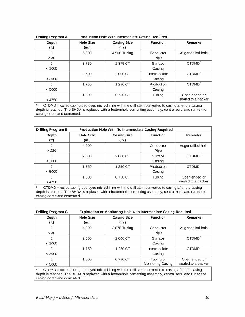
Three Generic Drilling Programs. Three generic drilling programs are proposed for productionmicroholes at a nonspecific site. Well Program “A” includes an intermediate casing. Well Program“B” does not. Well Program “C” produces an exploration hole for openhole logging or monitoring inan uncased bore, which is much too small for commercial production of fluids.
General Objectives:
TD: < 5000 ftPBTD: < 4980 ftDepth of production casing: < 5000 ftDepth of casing perforations: < 4800 - 4900 ftDepth of tubing: < 4750 ft
The drilling concept selects holes sizes and coiled-tubing drill stem/casing sizes to produce a 1-in.internal diameter casing at 5000 ft. It is assumed that an auger-drilled hole will be used for theconductor casing and it will be drilled to 20-ft or until 5 ft of hard rock is penetrated.
Road Map for a 5000-ft Microborehole 20
Drilling Program A Production Hole With Intermediate Casing Required
Depth(ft)
Hole Size(in.)
Casing Size(in.)
Function Remarks
0> 30
6.000 4.500 Tubing ConductorPipe
Auger drilled hole
0
< 1000
3.750 2.875 CT Surface
Casing
CTDMD*
0
< 2000
2.500 2.000 CT Intermediate
Casing
CTDMD*
0
< 5000
1.750 1.250 CT Production
Casing
CTDMD*
0
< 4750
1.000 0.750 CT Tubing Open ended orsealed to a packer
* CTDMD = coiled-tubing-deployed microdrilling with the drill stem converted to casing after the casingdepth is reached. The BHDA is replaced with a bottomhole cementing assembly, centralizers, and run to thecasing depth and cemented.
Drilling Program B Production Hole With No Intermediate Casing Required
Depth
(ft)
Hole Size
(in.)
Casing Size
(in.)
Function Remarks
0
> 230
4.000 Conductor
Pipe
Auger drilled hole
0
< 2000
2.500 2.000 CT Surface
Casing
CTDMD*
0< 5000
1.750 1.250 CT ProductionCasing
CTDMD*
0< 4750
1.000 0.750 CT Tubing Open ended orsealed to a packer
* CTDMD = coiled-tubing-deployed microdrilling with the drill stem converted to casing after the casingdepth is reached. The BHDA is replaced with a bottomhole cementing assembly, centralizers, and run to thecasing depth and cemented.
Drilling Program C Exploration or Monitoring Hole with Intermediate Casing Required
Depth(ft)
Hole Size(in.)
Casing Size(in.)
Function Remarks
0< 30
4.000 2.875 Tubing ConductorPipe
Auger drilled hole
0
< 1000
2.500 2.000 CT Surface
Casing
CTDMD*
0
< 2000
1.750 1.250 CT Intermediate
Casing
CTDMD*
0
< 5000
1.000 0.750 CT Tubing orMonitoring Casing
Open ended orsealed to a packer
* CTDMD = coiled-tubing-deployed microdrilling with the drill stem converted to casing after the casingdepth is reached. The BHDA is replaced with a bottomhole cementing assembly, centralizers, and run to thecasing depth and cemented.
Road Map for a 5000-ft Microborehole 21
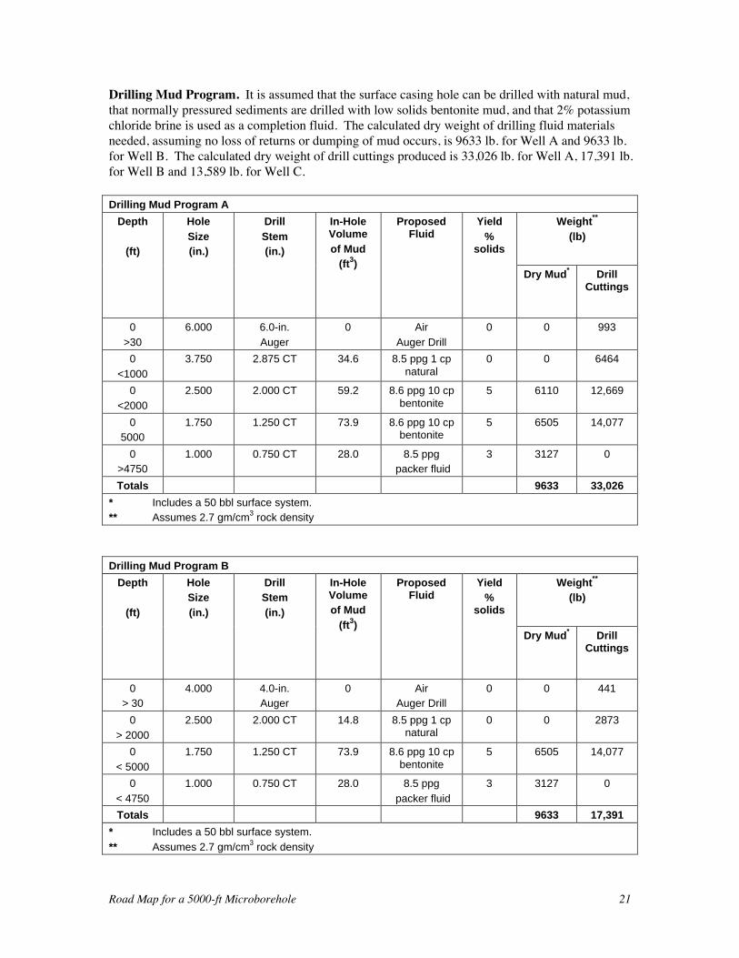
Drilling Mud Program. It is assumed that the surface casing hole can be drilled with natural mud,that normally pressured sediments are drilled with low solids bentonite mud, and that 2% potassiumchloride brine is used as a completion fluid. The calculated dry weight of drilling fluid materialsneeded, assuming no loss of returns or dumping of mud occurs, is 9633 lb. for Well A and 9633 lb.for Well B. The calculated dry weight of drill cuttings produced is 33,026 lb. for Well A, 17,391 lb.for Well B and 13,589 lb. for Well C.
Drilling Mud Program A
Weight**
(lb)
Depth
(ft)
Hole
Size(in.)
Drill
Stem(in.)
In-HoleVolume
of Mud(ft3)
ProposedFluid
Yield
%solids
Dry Mud* DrillCuttings
0
>30
6.000 6.0-in.
Auger
0 Air
Auger Drill
0 0 993
0
<1000
3.750 2.875 CT 34.6 8.5 ppg 1 cpnatural
0 0 6464
0
<2000
2.500 2.000 CT 59.2 8.6 ppg 10 cpbentonite
5 6110 12,669
05000
1.750 1.250 CT 73.9 8.6 ppg 10 cpbentonite
5 6505 14,077
0>4750
1.000 0.750 CT 28.0 8.5 ppg packer fluid
3 3127 0
Totals 9633 33,026
* Includes a 50 bbl surface system.** Assumes 2.7 gm/cm3 rock density
Drilling Mud Program B
Weight**
(lb)Depth
(ft)
HoleSize
(in.)
DrillStem
(in.)
In-HoleVolumeof Mud
(ft3)
ProposedFluid
Yield%
solids
Dry Mud* DrillCuttings
0> 30
4.000 4.0-in.Auger
0 AirAuger Drill
0 0 441
0
> 2000
2.500 2.000 CT 14.8 8.5 ppg 1 cpnatural
0 0 2873
0
< 5000
1.750 1.250 CT 73.9 8.6 ppg 10 cpbentonite
5 6505 14,077
0
< 4750
1.000 0.750 CT 28.0 8.5 ppg
packer fluid
3 3127 0
Totals 9633 17,391
* Includes a 50 bbl surface system.
** Assumes 2.7 gm/cm3 rock density
Road Map for a 5000-ft Microborehole 22
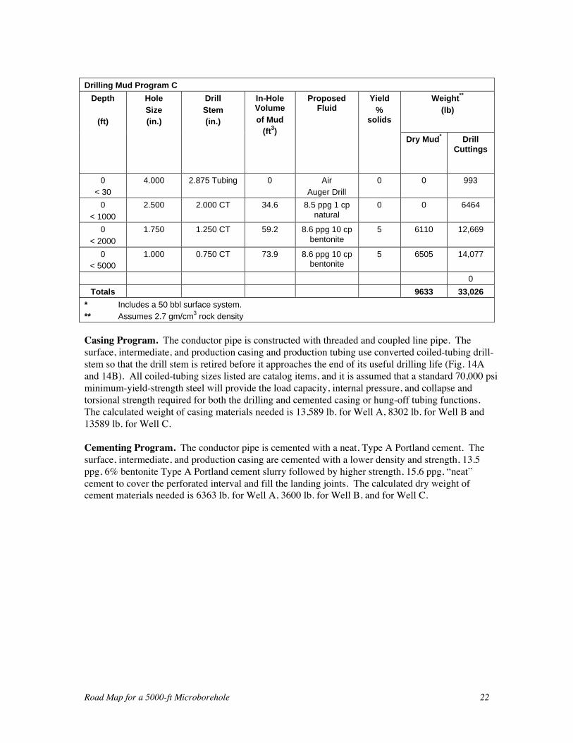
Drilling Mud Program C
Weight**
(lb)
Depth
(ft)
Hole
Size(in.)
Drill
Stem(in.)
In-HoleVolume
of Mud(ft3)
ProposedFluid
Yield
%solids
Dry Mud* DrillCuttings
0
< 30
4.000 2.875 Tubing 0 Air
Auger Drill
0 0 993
0
< 1000
2.500 2.000 CT 34.6 8.5 ppg 1 cpnatural
0 0 6464
0
< 2000
1.750 1.250 CT 59.2 8.6 ppg 10 cpbentonite
5 6110 12,669
0< 5000
1.000 0.750 CT 73.9 8.6 ppg 10 cpbentonite
5 6505 14,077
0
Totals 9633 33,026
* Includes a 50 bbl surface system.
** Assumes 2.7 gm/cm3 rock density
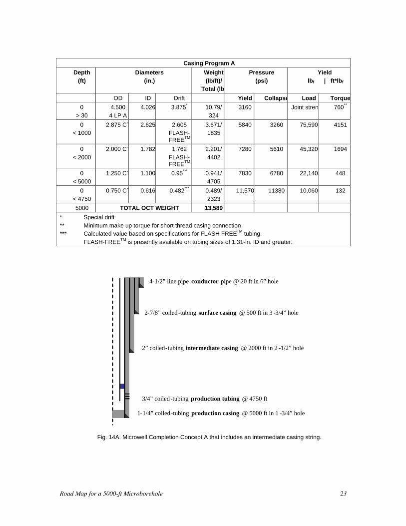
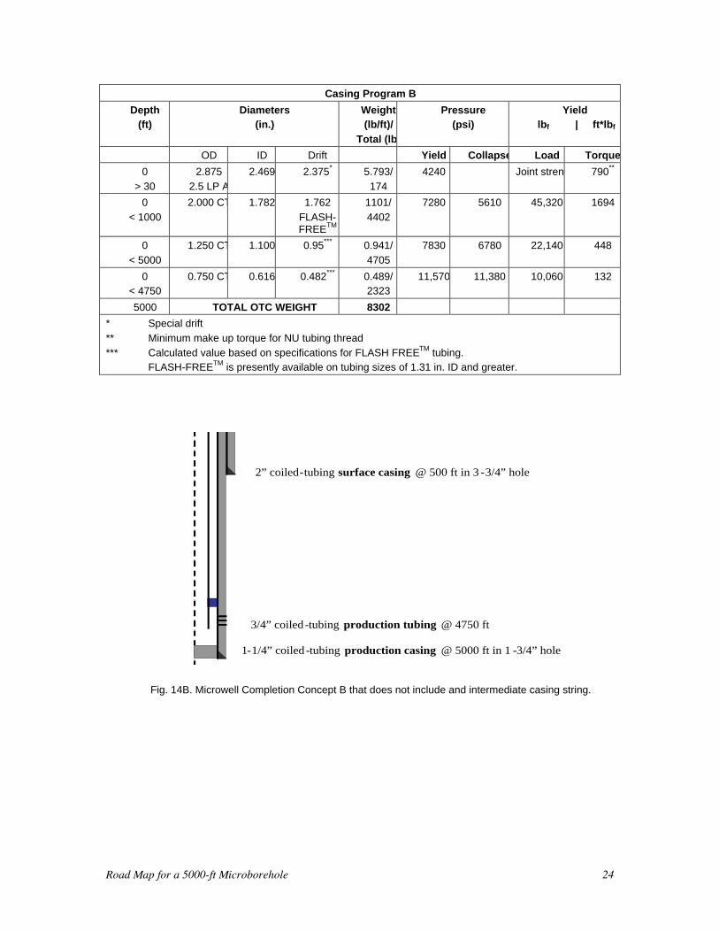
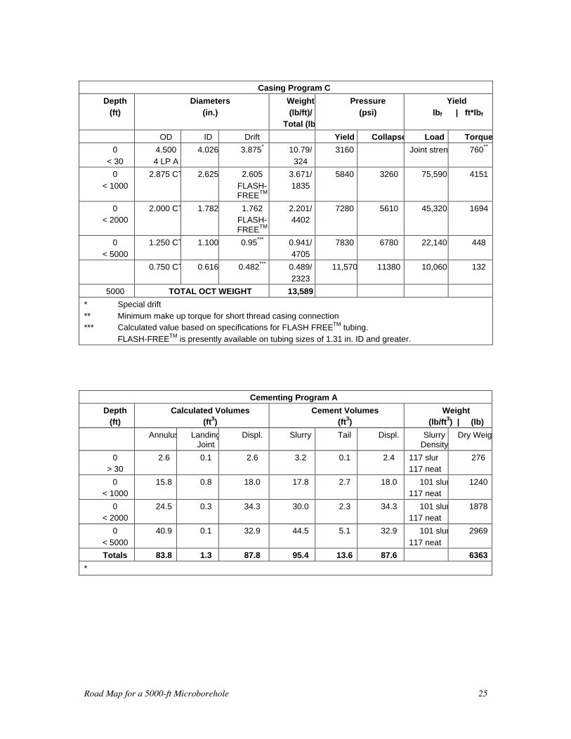
Casing Program. The conductor pipe is constructed with threaded and coupled line pipe. Thesurface, intermediate, and production casing and production tubing use converted coiled-tubing drill-stem so that the drill stem is retired before it approaches the end of its useful drilling life (Fig. 14Aand 14B). All coiled-tubing sizes listed are catalog items, and it is assumed that a standard 70,000 psiminimum-yield-strength steel will provide the load capacity, internal pressure, and collapse andtorsional strength required for both the drilling and cemented casing or hung-off tubing functions.The calculated weight of casing materials needed is 13,589 lb. for Well A, 8302 lb. for Well B and13589 lb. for Well C.
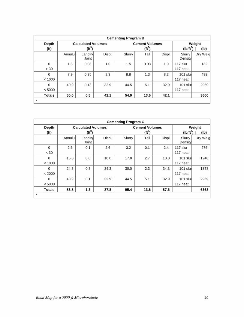
Cementing Program. The conductor pipe is cemented with a neat, Type A Portland cement. Thesurface, intermediate, and production casing are cemented with a lower density and strength, 13.5ppg, 6% bentonite Type A Portland cement slurry followed by higher strength, 15.6 ppg, “neat”cement to cover the perforated interval and fill the landing joints. The calculated dry weight ofcement materials needed is 6363 lb. for Well A, 3600 lb. for Well B, and for Well C.
Road Map for a 5000-ft Microborehole 23
Casing Program A
Depth
(ft)
Diameters
(in.)
Weight
(lb/ft)/Total (lb)
Pressure
(psi)
Yield
lbf | ft*lbf
OD ID Drift Yield Collapse Load Torque
0
> 30
4.500
4 LP A
4.026 3.875* 10.79/
324
3160 Joint strength 760**
0< 1000
2.875 CT 2.625 2.605FLASH-FREETM
3.671/1835
5840 3260 75,590 4151
0
< 2000
2.000 CT 1.782 1.762
FLASH-FREETM
2.201/
4402
7280 5610 45,320 1694
0
< 5000
1.250 CT 1.100 0.95*** 0.941/
4705
7830 6780 22,140 448
0
< 4750
0.750 CT 0.616 0.482*** 0.489/
2323
11,570 11380 10,060 132
5000 TOTAL OCT WEIGHT 13,589
* Special drift
** Minimum make up torque for short thread casing connection*** Calculated value based on specifications for FLASH FREETM tubing.
FLASH-FREETM is presently available on tubing sizes of 1.31-in. ID and greater.
2-7/8” coiled -tubing surface casing @ 500 ft in 3 -3/4” hole
4-1/2” line pipe conductor pipe @ 20 ft in 6” hole
2” coiled-tubing intermediate casing @ 2000 ft in 2 -1/2” hole
1-1/4” coiled -tubing production casing @ 5000 ft in 1 -3/4” hole
3/4” coiled -tubing production tubing @ 4750 ft
Fig. 14A. Microwell Completion Concept A that includes an intermediate casing string.
Road Map for a 5000-ft Microborehole 24
Casing Program B
Depth(ft)
Diameters(in.)
Weight(lb/ft)/
Total (lb)
Pressure(psi)
Yield lbf | ft*lbf
OD ID Drift Yield Collapse Load Torque
0
> 30
2.875
2.5 LP A
2.469 2.375* 5.793/
174
4240 Joint strength 790**
0
< 1000
2.000 CT 1.782 1.762
FLASH-FREETM
1101/
4402
7280 5610 45,320 1694
0
< 5000
1.250 CT 1.100 0.95*** 0.941/
4705
7830 6780 22,140 448
0< 4750
0.750 CT 0.616 0.482*** 0.489/2323
11,570 11,380 10,060 132
5000 TOTAL OTC WEIGHT 8302
* Special drift
** Minimum make up torque for NU tubing thread
*** Calculated value based on specifications for FLASH FREETM tubing.FLASH-FREETM is presently available on tubing sizes of 1.31 in. ID and greater.
2” coiled-tubing surface casing @ 500 ft in 3 -3/4” hole
2-7/8” line pipe conductor pipe @ 20 ft in 4” hole
1-1/4” coiled -tubing production casing @ 5000 ft in 1 -3/4” hole
3/4” coiled -tubing production tubing @ 4750 ft
Fig. 14B. Microwell Completion Concept B that does not include and intermediate casing string.
Road Map for a 5000-ft Microborehole 25
Casing Program C
Depth
(ft)
Diameters
(in.)
Weight
(lb/ft)/Total (lb)
Pressure
(psi)
Yield
lbf | ft*lbf
OD ID Drift Yield Collapse Load Torque
0
< 30
4.500
4 LP A
4.026 3.875* 10.79/
324
3160 Joint strength 760**
0
< 1000
2.875 CT 2.625 2.605
FLASH-FREETM
3.671/
1835
5840 3260 75,590 4151
0< 2000
2.000 CT 1.782 1.762FLASH-FREETM
2.201/4402
7280 5610 45,320 1694
0
< 5000
1.250 CT 1.100 0.95*** 0.941/
4705
7830 6780 22,140 448
0.750 CT 0.616 0.482*** 0.489/
2323
11,570 11380 10,060 132
5000 TOTAL OCT WEIGHT 13,589
* Special drift
** Minimum make up torque for short thread casing connection*** Calculated value based on specifications for FLASH FREETM tubing.
FLASH-FREETM is presently available on tubing sizes of 1.31 in. ID and greater.
Cementing Program A
Depth(ft)
Calculated Volumes(ft3)
Cement Volumes(ft3)
Weight(lb/ft3) | (lb)
Annulus LandingJoint
Displ. Slurry Tail Displ. SlurryDensity
Dry Weight
0> 30
2.6 0.1 2.6 3.2 0.1 2.4 117 slur117 neat
276
0< 1000
15.8 0.8 18.0 17.8 2.7 18.0 101 slur117 neat
1240
0< 2000
24.5 0.3 34.3 30.0 2.3 34.3 101 slur117 neat
1878
0
< 5000
40.9 0.1 32.9 44.5 5.1 32.9 101 slur
117 neat
2969
Totals 83.8 1.3 87.8 95.4 13.6 87.6 6363
*
Road Map for a 5000-ft Microborehole 26
Cementing Program B
Depth(ft)
Calculated Volumes(ft3)
Cement Volumes(ft3)
Weight(lb/ft3) | (lb)
Annulus LandingJoint
Displ. Slurry Tail Displ. SlurryDensity
Dry Weight
0> 30
1.3 0.03 1.0 1.5 0.03 1.0 117 slur117 neat
132
0< 1000
7.9 0.35 8.3 8.8 1.3 8.3 101 slur117 neat
499
0< 5000
40.9 0.13 32.9 44.5 5.1 32.9 101 slur117 neat
2969
Totals 50.0 0.5 42.1 54.9 13.6 42.1 3600
*
Cementing Program C
Depth
(ft)
Calculated Volumes
(ft3)
Cement Volumes
(ft3)
Weight
(lb/ft3) | (lb)
Annulus LandingJoint
Displ. Slurry Tail Displ. SlurryDensity
Dry Weight
0
< 30
2.6 0.1 2.6 3.2 0.1 2.4 117 slur
117 neat
276
0
< 1000
15.8 0.8 18.0 17.8 2.7 18.0 101 slur
117 neat
1240
0
< 2000
24.5 0.3 34.3 30.0 2.3 34.3 101 slur
117 neat
1878
0
< 5000
40.9 0.1 32.9 44.5 5.1 32.9 101 slur
117 neat
2969
Totals 83.8 1.3 87.8 95.4 13.6 87.6 6363
*
Road Map for a 5000-ft Microborehole 27
THE ROADMAP
Discussion. A review of the theoretical work, laboratory-scale, and 0- to 700-ft-deep fielddemonstrations described above leads us to the following conclusions:1. The equipment, systems, and services used in the recent field demonstrations will only be suitable
for a 5000-ft-deep drilling demonstration in the most ideal drilling site. Such sites may not existanywhere where drilling 5000-ft holes has significant commercial value.
2. The full value of microdrilling will not be achieved unless the capability to drill the hole sizesproposed in this document is developed. To retreat to working at the size and present performanceof the off-the-shelf equipment now available will lead to reduced performance that will quicklypush us to the small end of slimhole drilling technology. Only marginal cost-benefits offset bylarge loss of performance, utility, and capability will be realized. Existing downhole equipmentwill have to be downsized to 50% of its present size to achieve the microwell designs describedpreviously. Microholes drilled with presently available equipment will be twice the proposeddiameter and require approximately four times the mobilization and operating mass that has beenestimated above. Either a larger rig crew will be needed to man-handle equipment, or heavy,highly automated handling equipment will have to be mobilized.
3. A large, well planned, technology development program will have to be funded by the oil industrywith limited leverage with DOE funding to achieve the 5000-ft deep, microdrilling demonstrationsproposed.
4. Microhole technology development can be accelerated through internal investments by thefollowing concerns:a. Future microdrilling contractors including oil and gas service companies, oil field, mining, and
domestic water drilling contractors.b. Future equipment suppliers including oil and gas service companies and mechanical
equipment and instrumentation manufacturers.c. Future material suppliers including oil and gas service companies and cement and drilling
fluid additive suppliers, mining and domestic water drilling service companies.
NEEDED TECHNOLOGY DEVELOPMENT
Five critical and five less critical technology development initiatives have been identified that areneeded to enhance the probability of producing a 5000-ft microhole in a less than ideal environment.Most can be downsized from mature, conventional-sized technology. Basic engineering can beapplied to determine the appropriate performance requirements once the geometric scaling parametersare determined. Some technology development is needed to downsize less mature technology. Thepath to a microdrill design for this technology is uncertain but not expected to require breakthroughdevelopments. Extensive systems analysis will be required to assure that downsized designs areproperly scaled to achieve optimal performance. Under each item we have identified target sponsorsthat would plausibly support the effort, a target subcontractor that will lead the required developmentwork, and a one-significant-figure cost estimate for the development of the first prototypes needed toconduct early demonstrations.
These are technologies that must be demonstrated before microdrilling can move beyond specialty andniche applications. A brief description and detail on each of the technology development itemsfollows. A summary table of the items titled “The Road Map” includes a list of the items, sponsorsand contractors, and very rough development time and cost estimates.
Road Map for a 5000-ft Microborehole 28
Microdrill motors. Developments in the microdrill motor area will first require enhancing a maturetechnology for standard PDMs, and be followed by the development of new downhole hydraulichammers and compressible-fluid-powered PDMs. These technologies will need to be adapted to thespecific performance that microdrilling requires in the specific target rocks. The designs mustsupport high conversion efficiency using both Newtonian and non-Newtonian fluids with some drillsolids content. A tradeoff between motor life and mud cleaning performance will have to beoptimized in field demonstrations. The diameters shown in drilling programs a, b, and c (below) arethe coiled-tubing diameters on which the motors will be deployed, and therefore are minimum valuesthat will have to be specified at the completion of a full systems analysis.1. Rotary PDMs. Micro PDMs must convert low-flow and high-pressure hydraulic power to the
torque and speed needed to produce small chips in a very wide range of low and medium strengthsedimentary rocks using low weight-on-bit PDC and diamond bits. Theoretical designs areexpected to be straightforward for incompressible fluids. The major challenge will be to developtechnology to fabricate the rotors and stators to the tolerances needed to produce the highconversion efficiency that will be required for high performance drilling. The following areneeded:a. The design and fabrication of 3/4-in. motors for cement and wiper plug drilling; sand, scale,
and paraffin clean out; and limited duty openhole drilling.b. The design and fabrication of 1-1/4-in. and 2-in. motors for cement and wiper plug drilling
and heavy duty openhole drilling.2. Integrated rotary-percussion motors (IRPM). IRPMs must convert low-flow and high-
pressure hydraulic power to the impact amplitudes and frequencies needed to break medium andhigh strength sedimentary rocks using low weight-on-bit and integral hammer bits. The IRPMmust also produce the torque and rotary speed needed to properly index the percussion bit at low-to-moderate weight-on-bit. In early versions of the IRPM, the rotary speed and frequency mayneed to be controlled by the common flow rate through each converter. Advanced IRPMs mayrequire independent control to produce an optimum indexing for the rock being drilled. Thedesigns must include a reflector/tubing isolation sub-component that will protect the downholesensors and telemetry in the instrumentation sub and the bottom of the coiled-tubing drill stem,from both pressure pulsation and the mechanical vibration generated by the converter and thebit/rock interaction. We do not believe that designs for the envisioned integral unit exist, and thusa significant development program will be needed. Developing technology to fabricate theIRPMs to the tolerances required to produce high conversion efficiency may require significantinvestment. The following are needed:a. The design and fabrication of 3/4-in. IRPM for cement and wiper plug drilling; sand, scale,
and paraffin clean out; and limited duty openhole drilling.b. The design and fabrication of 1-1/4-in., 2-in., and 2-7/8-in. IRPMs for cement and wiper plug
drilling and heavy duty openhole drilling.
Microdrill bits. Microbit designs must support the efficient production of small chips using thePDMs and IRPMs described above. 3-3/4-in., 2-5/8-in., 1-3/4-in., and 1-in. bits will be needed. Thediameters are approximate and will have to be specified at the completion of a full systems analysis.Many of the larger size bits may already exist in a satisfactory design. Most of the smaller bits willlikely have to be downsized from larger designs. The following are needed:1. PDC rotary bits. High rotary speed bits with a low threshold thrust designed to penetrate soft
and medium strength rocks.
Road Map for a 5000-ft Microborehole 29
2. Percussion hammer bits. Bits designed to operate at high frequency/high rotary speeds andproduce small chips at low threshold thrusts in medium and high strength rocks.
3. Special bits. Microbits to drill cement and wiper plugs.Downhole sensing and control. Robust, accurate, microsensors and microsized processing andtelemetry circuits are needed to control the drilling process. First generation sensors should besufficiently resilient to operate in the instrumentation and telemetry sub at the bottom of the coiled-tubing and above the drilling motor and isolation sub-component, if present. Second generationsensors should be sufficiently robust to operate in a bit sub between the drilling motor and themicrobit.1. Existing sensors and telemetry circuits that perform the following services will have to beresized to fit in micro-housings below the coiled tubing or below the drilling motor:
a. Drilling process sensors(i) drill thrust (weight-on-bit)(ii) drill torque
2. Directional trajectory sensorsa. inclinometerb. magnetometer/gyro
3. Telemetry and processing circuitsa. Signal conditioning, A/D, and telemetry transmission and reception circuits
Downhole drilling controls. Existing sensors and circuits that perform the following services willhave to be resized to fit in a microhousing below the coiled tubing or a bit sub between the microbitand drill motor. First generation technology will use downhole measurements to guide surfacecontrol of drill-stem insertion to produce weight-on-bit and flow rates to produce the torque and rpmdesired. The second-generation technology development will support real-time, downhole drillingprocess control and steering for directional drilling with near-bit telemetry and control. Thefollowing is needed:1. Two way radio circuits and antennas2. Motor or valve controller circuits
a. Weight-on-bit thrust controlb. Directional control including:
(i) Deviation control – variable bent sub and(ii) Orientation control – bent sub orientation motor or(iii) Combined deviation/orientation sub (array of hydraulic pistons push the bit to one side of
the hole while centering the top of the sub to create the bend desired)
Micro-Casing Installation and Cementing. The following are needed:1. Microsized cementing tools for coiled tubing used for casing
a. Wiper plugs for non-flash free and flash free coiled-tubing cementing(i) Plug dropping manifold(ii) Landing collars /plug catcher
b. Float valves
Road Map for a 5000-ft Microborehole 30
c. Casing guide shoesd. Wrap-around, clamp-on centralizers for coiled tubing
2. Slurries for small annulus cementinga. Low viscosityb. Low densityc. Longer thickening times to support slower placement
3. Micro Production and Monitoring. The following are needed:a. Microsized well perforation tools for small diameter coiled tubing
(i) Coiled tubing deployed perforators(a) Abrasive jet(b) Shaped charged perforator
(ii) Wireline-deployed perforatorsb. Gravel packing design, simulations, and field demonstrations.c. Basic stimulation designs, simulations, and field demonstrations
(i) Perforation breakdown treatments(ii) Chemical dissolution treatments(iii) Hydro-fracturing treatments
Power and cutting transport modeling. Published models are not very accurate in the turbulentflow regime, and empirical annular-flow correction factors are untested for the proposed microhole-sized experimental data. Experimental data needs to be generated for microsized tubes and annuli totest and validate various commercial and published models. Where models are found to be lacking,new or modified models should be developed and verified. Models accounting for the following areneeded:1. Hydraulic power transport
a. Non-Newtonian flowb. Annular flowc. Cuttings transports
2. Pneumatic transporta. Newtonian compressible flowb. Foam flowc. Annular flowd. Cuttings transport
LESS CRITICAL TECHNOLOGY NEEDED
These are technologies that will improve the economics and versatility of microdrilling, but are notneeded to accomplish drilling 5000 ft microholes. A brief description and detail on each of thetechnology development items follows, and a summary table of the items titled “The Road Map”includes a list of the items, sponsors and contractors and very rough development time and costestimates.
Road Map for a 5000-ft Microborehole 31
High-pressure mud pumping. Demonstrations are needed of a small centrifugal horizontal pump, apressure multiplier, and other appropriate, high-pressure, mud pumping technologies including sumppumps. Special multiplex pump valves and plunger packing systems should be tested to determine ifhigh pump maintenance costs can be significantly reduced by using nontraditional pumpingequipment.Advanced drilling fluid cleaning. Demonstrations are needed of advanced, nonstandard cuttingsand drill solids separation technology, beyond an enhanced cleaning system based on presenttechnology. This should be done to determine if high mud-pump maintenance costs can besignificantly reduced and drilling motor life is increased using nontraditional separation equipmentand configurations.Coiled-tubing fabrication. Development is needed of technology for fabrication of coiled tubingspecifically for microdrilling and conversion to cemented casing. To be considered are:1. Flash-free coiled-tubing for the smallest sizes2. Telemetry cables. Installation technology to insert and remove cables in small-diameter, coiled
tubing is needed to provide hardwire telemetry for downhole sensors and controllers. (This canbe done manually by unreeling the tubing and inserting a stiff wire to pull through a telemetrycable. This method is not very practical for 5000-ft-long cables which must be removed andreinstalled in a smaller tubing each time a drill stem is converted to casing).
3. Cementing wiper plugs for coiled tubingCoiled-tubing deployed fishing. While wash-over and fishing operations with mining drill-rigtechnology has proven to be a viable method of retrieving fish from microholes at shallow depths, itwill be far less attractive as the depth of the fish increases, and trip time for the drill rods increasesdramatically. Coiled-tubing-deployed fishing technology requirements identified thus far include thefollowing equipment sized to support small-diameter coiled tubing operations, including 3/4-in., 1-1/4-in. and 2-in. tubing. Needed are:1. Fishing PDM. This should be a high-torque, low-rotary-speed motor to slowly rotate fishing
tools and wash-over pipe while circulating at a low flow rate.2. Flow-though jars and bumper sub. While small-diameter jars and bumper subs for wireline
fishing are available, the inability to circulate fluid through them to wash the fishing tools ontothe fish greatly reduces the chance of engaging the fish. Standard drill stem-deployed fishingtools need to be scaled to support fishing on small diameter coiled tubing.
3. Fishing tools. A greater selection of overshots, spears, and safety release tools will need to bedeveloped to support small diameter tools.
Microdrill air motor. New designs must have high conversion efficiency when using compressibleNewtonian air and mist, or non-Newtonian foams with some drill solids content in the continuousliquid phase. This technology will be needed to penetrate highly under-pressured formations anddepleted reservoirs. The diameters shown below are approximate and will have to be specified at thecompletion of a full systems analysis. This work should only be undertaken after a theoreticalthermodynamic/compressible flow systems analysis is completed and shows that power transport to5000-ft in a microhole is sufficient to produce a realistic penetration rate. Needed are:1. Rotary, positive displacement, air motor (PDAM) technology. Micro PDAMs must convert
low-flow and high-pressure pneumatic power to the torque and speed needed to produce smallchips in a very wide range of low and medium strength sedimentary rocks using low weight-on-bit PDC and diamond bits. Theoretical designs for compressible fluids have been proposed butmost have not been fabricated and tested. Using traditional incompressible fluid designs for
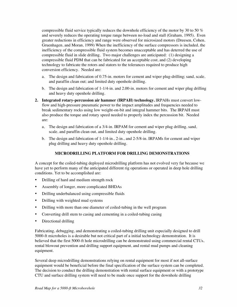
Road Map for a 5000-ft Microborehole 32
compressible fluid service typically reduces the downhole efficiency of the motor by 30 to 50 %and severely reduces the operating torque range between no-load and stall (Graham, 1995). Evengreater reductions in efficiency and range were observed for microsized motors (Dreesen, Cohen,Gruenhagen, and Moran, 1999) When the inefficiency of the surface compressors is included, theinefficiency of the compressible fluid system becomes unacceptable and has deterred the use ofcompressible fluid in slide drilling. Two major challenges are anticipated: (1) designing acompressible fluid PDM that can be fabricated for an acceptable cost, and (2) developingtechnology to fabricate the rotors and stators to the tolerances required to produce highconversion efficiency. Needed are:a. The design and fabrication of 0.75-in. motors for cement and wiper plug-drilling; sand, scale,
and paraffin clean out; and limited duty openhole drilling.b. The design and fabrication of 1-1/4-in. and 2.00-in. motors for cement and wiper plug drilling
and heavy duty openhole drilling.2. Integrated rotary-percussion air hammer (IRPAH) technology. IRPAHs must convert low-
flow and high-pressure pneumatic power to the impact amplitudes and frequencies needed tobreak sedimentary rocks using low weight-on-bit and integral hammer bits. The IRPAH mustalso produce the torque and rotary speed needed to properly index the percussion bit. Neededare:a, The design and fabrication of a 3/4-in. IRPAM for cement and wiper plug drilling, sand,
scale, and paraffin clean out, and limited duty openhole drilling.b. The design and fabrication of 1-1/4-in., 2-in., and 2-5/8-in. IRPAMs for cement and wiper
plug drilling and heavy duty openhole drilling.
MICRODRILLING PLATFORM FOR DRILLING DEMONSTRATIONS
A concept for the coiled-tubing deployed microdrilling platform has not evolved very far because wehave yet to perform many of the anticipated different rig operations or operated in deep hole drillingconditions. Yet to be accomplished are:• Drilling of hard and medium strength rock• Assembly of longer, more complicated BHDAs• Drilling underbalanced using compressible fluids• Drilling with weighted mud systems• Drilling with more than one diameter of coiled-tubing in the well program• Converting drill stem to casing and cementing in a coiled-tubing casing• Directional drilling
Fabricating, debugging, and demonstrating a coiled-tubing drilling unit especially designed to drill5000-ft microholes is a desirable but not critical part of a initial technology demonstration. It isbelieved that the first 5000-ft hole microdrilling can be demonstrated using commercial rental CTUs,rental blowout prevention and drilling support equipment, and rental mud pumps and cleaningequipment.
Several deep microdrilling demonstrations relying on rental equipment for most if not all-surfaceequipment would be beneficial before the final specification of the surface system can be completed.The decision to conduct the drilling demonstration with rental surface equipment or with a prototypeCTU and surface drilling system will need to be made once support for the downhole drilling
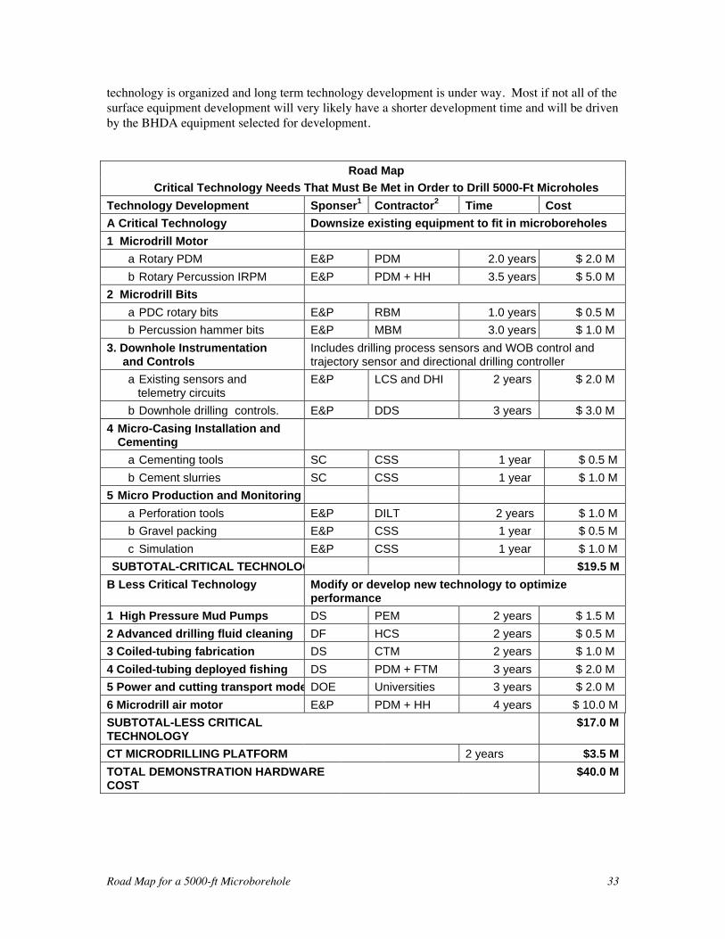
Road Map for a 5000-ft Microborehole 33
technology is organized and long term technology development is under way. Most if not all of thesurface equipment development will very likely have a shorter development time and will be drivenby the BHDA equipment selected for development.
Road Map
Critical Technology Needs That Must Be Met in Order to Drill 5000-Ft Microholes
Technology Development Sponser1 Contractor2 Time Cost
A Critical Technology Downsize existing equipment to fit in microboreholes
1 Microdrill Motor
a Rotary PDM E&P PDM 2.0 years $ 2.0 M
b Rotary Percussion IRPM E&P PDM + HH 3.5 years $ 5.0 M
2 Microdrill Bits
a PDC rotary bits E&P RBM 1.0 years $ 0.5 M
b Percussion hammer bits E&P MBM 3.0 years $ 1.0 M
3. Downhole Instrumentationand Controls
Includes drilling process sensors and WOB control andtrajectory sensor and directional drilling controller
a Existing sensors and telemetry circuits
E&P LCS and DHI 2 years $ 2.0 M
b Downhole drilling controls. E&P DDS 3 years $ 3.0 M
4 Micro-Casing Installation andCementing
a Cementing tools SC CSS 1 year $ 0.5 M
b Cement slurries SC CSS 1 year $ 1.0 M
5 Micro Production and Monitoring
a Perforation tools E&P DILT 2 years $ 1.0 M
b Gravel packing E&P CSS 1 year $ 0.5 M
c Simulation E&P CSS 1 year $ 1.0 M
SUBTOTAL-CRITICAL TECHNOLOGY $19.5 M
B Less Critical Technology Modify or develop new technology to optimizeperformance
1 High Pressure Mud Pumps DS PEM 2 years $ 1.5 M
2 Advanced drilling fluid cleaning DF HCS 2 years $ 0.5 M
3 Coiled-tubing fabrication DS CTM 2 years $ 1.0 M
4 Coiled-tubing deployed fishing DS PDM + FTM 3 years $ 2.0 M
5 Power and cutting transport modelDOE Universities 3 years $ 2.0 M
6 Microdrill air motor E&P PDM + HH 4 years $ 10.0 M
SUBTOTAL-LESS CRITICALTECHNOLOGY
$17.0 M
CT MICRODRILLING PLATFORM 2 years $3.5 M
TOTAL DEMONSTRATION HARDWARECOST
$40.0 M
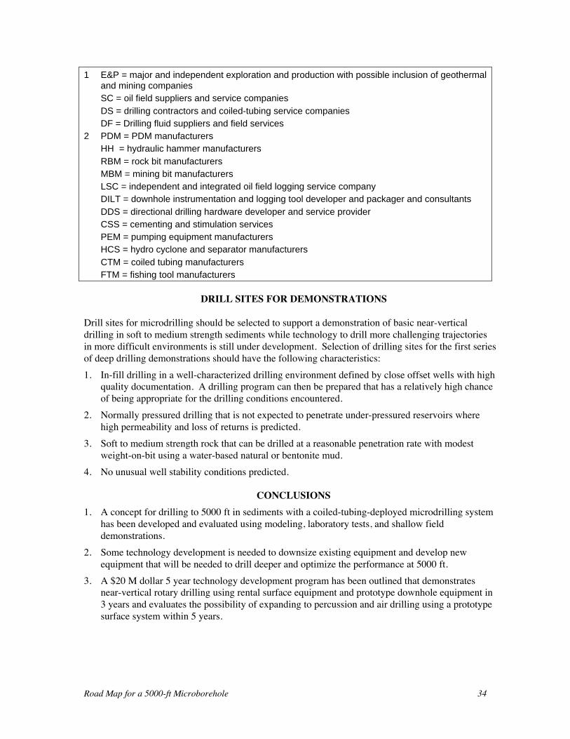
Road Map for a 5000-ft Microborehole 34
1 E&P = major and independent exploration and production with possible inclusion of geothermaland mining companiesSC = oil field suppliers and service companiesDS = drilling contractors and coiled-tubing service companiesDF = Drilling fluid suppliers and field services
2 PDM = PDM manufacturersHH = hydraulic hammer manufacturersRBM = rock bit manufacturersMBM = mining bit manufacturersLSC = independent and integrated oil field logging service companyDILT = downhole instrumentation and logging tool developer and packager and consultantsDDS = directional drilling hardware developer and service providerCSS = cementing and stimulation servicesPEM = pumping equipment manufacturersHCS = hydro cyclone and separator manufacturersCTM = coiled tubing manufacturersFTM = fishing tool manufacturers
DRILL SITES FOR DEMONSTRATIONS
Drill sites for microdrilling should be selected to support a demonstration of basic near-verticaldrilling in soft to medium strength sediments while technology to drill more challenging trajectoriesin more difficult environments is still under development. Selection of drilling sites for the first seriesof deep drilling demonstrations should have the following characteristics:1. In-fill drilling in a well-characterized drilling environment defined by close offset wells with high
quality documentation. A drilling program can then be prepared that has a relatively high chanceof being appropriate for the drilling conditions encountered.
2. Normally pressured drilling that is not expected to penetrate under-pressured reservoirs wherehigh permeability and loss of returns is predicted.
3. Soft to medium strength rock that can be drilled at a reasonable penetration rate with modestweight-on-bit using a water-based natural or bentonite mud.
4. No unusual well stability conditions predicted.
CONCLUSIONS1. A concept for drilling to 5000 ft in sediments with a coiled-tubing-deployed microdrilling system
has been developed and evaluated using modeling, laboratory tests, and shallow fielddemonstrations.
2. Some technology development is needed to downsize existing equipment and develop newequipment that will be needed to drill deeper and optimize the performance at 5000 ft.
3. A $20 M dollar 5 year technology development program has been outlined that demonstratesnear-vertical rotary drilling using rental surface equipment and prototype downhole equipment in3 years and evaluates the possibility of expanding to percussion and air drilling using a prototypesurface system within 5 years.
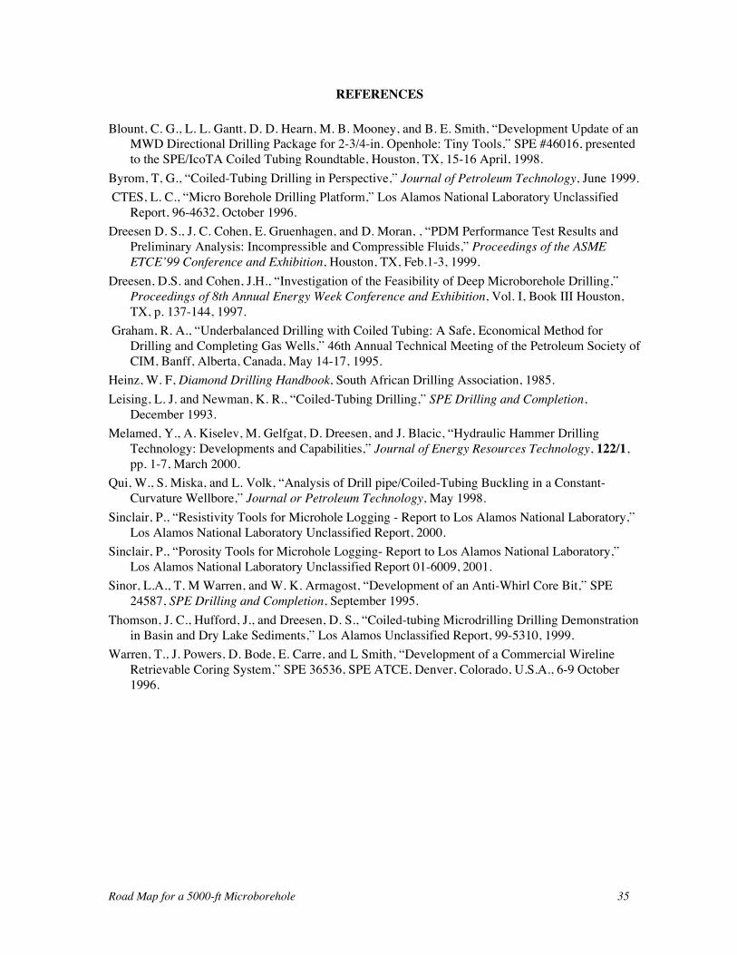
Road Map for a 5000-ft Microborehole 35
REFERENCES
Blount, C. G., L. L. Gantt, D. D. Hearn, M. B. Mooney, and B. E. Smith, “Development Update of anMWD Directional Drilling Package for 2-3/4-in. Openhole: Tiny Tools,” SPE #46016, presentedto the SPE/IcoTA Coiled Tubing Roundtable, Houston, TX, 15-16 April, 1998.
Byrom, T, G., “Coiled-Tubing Drilling in Perspective,” Journal of Petroleum Technology, June 1999. CTES, L. C., “Micro Borehole Drilling Platform,” Los Alamos National Laboratory Unclassified
Report, 96-4632, October 1996.Dreesen D. S., J. C. Cohen, E. Gruenhagen, and D. Moran, , “PDM Performance Test Results and
Preliminary Analysis: Incompressible and Compressible Fluids,” Proceedings of the ASMEETCE’99 Conference and Exhibition, Houston, TX, Feb.1-3, 1999.
Dreesen, D.S. and Cohen, J.H., “Investigation of the Feasibility of Deep Microborehole Drilling,”Proceedings of 8th Annual Energy Week Conference and Exhibition, Vol. I, Book III Houston,TX, p. 137-144, 1997.
Graham, R. A., “Underbalanced Drilling with Coiled Tubing: A Safe, Economical Method forDrilling and Completing Gas Wells,” 46th Annual Technical Meeting of the Petroleum Society ofCIM, Banff, Alberta, Canada, May 14-17, 1995.
Heinz, W. F, Diamond Drilling Handbook, South African Drilling Association, 1985.Leising, L. J. and Newman, K. R., “Coiled-Tubing Drilling,” SPE Drilling and Completion,
December 1993.Melamed, Y., A. Kiselev, M. Gelfgat, D. Dreesen, and J. Blacic, “Hydraulic Hammer Drilling
Technology: Developments and Capabilities,” Journal of Energy Resources Technology, 122/1,pp. 1-7, March 2000.
Qui, W., S. Miska, and L. Volk, “Analysis of Drill pipe/Coiled-Tubing Buckling in a Constant-Curvature Wellbore,” Journal or Petroleum Technology, May 1998.
Sinclair, P., “Resistivity Tools for Microhole Logging - Report to Los Alamos National Laboratory,”Los Alamos National Laboratory Unclassified Report, 2000.
Sinclair, P., “Porosity Tools for Microhole Logging- Report to Los Alamos National Laboratory,”Los Alamos National Laboratory Unclassified Report 01-6009, 2001.
Sinor, L.A., T. M Warren, and W. K. Armagost, “Development of an Anti-Whirl Core Bit,” SPE24587, SPE Drilling and Completion, September 1995.
Thomson, J. C., Hufford, J., and Dreesen, D. S., “Coiled-tubing Microdrilling Drilling Demonstrationin Basin and Dry Lake Sediments,” Los Alamos Unclassified Report, 99-5310, 1999.
Warren, T., J. Powers, D. Bode, E. Carre, and L Smith, “Development of a Commercial WirelineRetrievable Coring System,” SPE 36536, SPE ATCE, Denver, Colorado, U.S.A., 6-9 October1996.
Road Map for a 5000-ft Microborehole 36
APPENDIX
FIELD DRILLING DEMONSTRATIONS
Fenton Hill Site, Sandoval County, NM. Three microwells were drill at the Los Alamos NationalLaboratory Hot Dry Rock Geothermal Test Site.The first well was drilled to 110-ft through welded volcanic tuff with a 1-3/4 in. drag bit. At thatdepth the BHDA plugged off and was found to be stuck when the coiled-tubing was tensioned.Attempts to pull the BHDA, using the rig leveling jacks and a reel lock, sheared the pins in the releasesub leaving the BHDA on bottom. After fishing the motor out of the hole, it was found that the statorrubber had been pumped out of its housing and plugged off in the lower motor (flexible shaft)housing. It is believed that the bit locked up as the limber BHDA drilled into a slightly off axisfracture and the torque-induced pressure surge caused the stator failure. After circulation was lost,cuttings settled around the bit and planted the BHDA.A second 2-3/8-in. hole was drilled to 90-ft to provide a geophone placement hole.A third 1-3/4-in. hole was recently drilled to 223 ft where a complete loss of returns occurred.Several attempts were made to seal off the loss zones, and the well was drilled with no return to 262ft.Basin and Range Dry-Lake-Bed Sediments. Four 2-3/8-in. OD microholes were drilled to depthsbetween 315 ft and 550 ft (Thomson, Hufford, and Dreesen, 1999). On the first two holes it wasquickly learned that:1. A 13-ft deep conductor pipe was not sufficient to prevent fracturing to the surface at the flow rate
needed to operate the off-the-shelf PDMs above their stall point.2. The available drag and tri-cone bits were not suitable for drilling the high clay formation with
natural or bentonite mud. It is assumed that bit balling was the cause of the observed poor drillingperformance and any technology that would improve drilling performance plagued by bit ballingwould improve microdrilling performance if the approach was compatible with the microdrillingsystem.
Deeper conductor pipes and slightly sandier clay on the second two holes resulted in an exemplarydemonstration of the microdrilling concept in soft unconsolidated or poorly consolidated, lakebed-deposited shales and clays. The major remaining challenges at the end of the demonstration were:1. Replace the triplex plunger pump (a high-pressure, triplex water pump), with a pump better suited
for pumping drilling mud.2. Improve the performance of the mud cleaning system.3. Find bits better suited to drilling high clay formations (or drill with oil base mud).4. Develop a PDM that converts high-pressure, low-flow-rate circulation to a high speed, high power
(torque) output.Evaluation of the Basin and Range Dry-Lake-Bed Sediment drilling campaign produced a list of rigmodifications that were needed to address specific operational deficiencies that were identified. Theyincluded:
Road Map for a 5000-ft Microborehole 37
1. The hydraulic system on the CTU was overheating while drilling with moderate or high weight-on-bit.
2. The coiled-tubing injector was incapable of applying a steady compression load on the coiledtubing to produce a steady compression (weight-on-bit) that is needed for shallow drilling.
3. The reeling system and the controls allowed the coil to swarm during reeling and unreeling.4. The trailer axles and frame supporting the tubing reel were not structurally sound and the frame
cracked in several places.5. The triplex pump was not well suited for high viscosity fluids and slurries.6. The direct-drive, gas-engine-powered, triplex pump did not provide the flow rate control needed to
conduct openhole drilling.The redesign and repair of the frame and replacement of the axle corrected the structural concerns.Most of the remaining deficiencies were corrected with a complete redesign of the hydraulic systemthat included a new hydraulic pump, a variable speed hydraulic motor to drive the mud pump, agreatly enhanced fluid cooler, and compatible reel and tubing injector locks and controllers. Thepiston-style water pump was replaced with a high-pressure triplex plunger mud pump, but this did notfully eliminate the problems experienced with the water pump.On each of the four holes, a 1.66-in. OD PVC casing was run and sealed to the annulus with abentonite grout displaced with a wiper plug and water. The wiper plug locked into a landing collar onthe bottom of the casing and the casings were de-watered with compressed nitrogen circulatedthrough a 3/8-in. polyflow tubing. All of the casings were installed without any major difficulty, butthe casing on the last two wells refilled with water. The source of the water was either a defectivecasing-joint below the water table or the wiper plug. To preclude any future wiper plug leak, alanding joint was added between the casing shoe and the landing collar to assure that some cementwould remain in the bottom joint below the landing collar. The 1.66 OD casing joints have a buttressthread and an o-ring seal. To preclude a joint leak, extra care is required to assure that each joint isequipped with an o-ring and the o-ring is not damaged as the joint is made up.
San Ysidro Site, Sandoval County, NM. Six 1-3/4-in. and 2-3/8-in. OD microholes were drilled todepths between 182 ft and 706 ft in soft unconsolidated or poorly consolidated, blow sand andstreambed deposits.The first two holes were drilled in a valley floor and encountered a thin hard formation in the intervalbetween 182-ft and 189-ft depth. In both wells the hard spot could not be drilled with the rotarydrilling assemblies that were available. The first hole was abandoned at 182 ft and the second holewas advanced through 1/2 ft of hard formation using a rental percussion drilling assembly.Considerable damage to the coiled tubing (and possibly to the bore wall) occurred while drilling theshort section. After cutting off 178 ft of coiled tubing, rotary drilling resumed and reached a depth of599 ft before well stability problems made it impossible to advance the hole further. Severe washouts and hole collapse occurred after two artesian flows were penetrated at 306 and 412 ft. Thecombination of the flow needed to operate the drilling motor and the artesian flow caused erosion ofthe bore. The daily drilling routine with overnight shutdowns increased formation exposure time tocross flow and unnatural water until massive hole wash outs and collapse were observed. As the borediameter increased beyond the bit size the coiled tubing was inadvertently compressed beyond itsallowable (critical buckling) load.The conductor pipe was not set deep enough to control the flow and the conductor pipe was pulledout of the borehole when buckled coiled-tubing was removed from the bore and hung up in theconductor pipe’s shoe. Several attempts were made to run and cement-in 1.66-in. OD PVC casing
Road Map for a 5000-ft Microborehole 38
using a conventional rotary mining drill rig and drill rods as a wash-over pipe to reenter the bore andguide the casing to bottom. Casing was run to the bottom of the drill rods and the drill rods wereremoved on each attempt. However, attempts to cement the casing were plagued with difficulty inestablishing full returns prior to pumping cement and partial or total hole collapse when lostcirculation material (LCM) or cement was circulated up the annulus. The casing was left full ofcement when the last attempt to cement the casing failed to bring significant cement up the annulus.The well was successfully plugged and abandoned using the rotary rig and a coring assembly to washover the cement-filled plastic casing and to spot cement plugs in the annulus.The four holes were drilled on a mesa top that was about 100 ft above and one mile to the north of thevalley floor wells. The site was selected with the expectation that the elevation would precludeartesian flow if the same aquifers were penetrated by the mesa top wells. 100 ft of 2-7/8 in. ODcasing was cemented into 4-in. auger-drilled holes to serve as conductor pipes.The first well was drilled with coiled tubing to 360 ft with a 1-3/4-in. drag bit when a shear pin failurein the shear release sub left the BHDA on bottom. The hole was reamed to 2-3/8 in. with a drag bitand an overshot and bumper sub (without an internal circulation port) were run on coiled tubing tofish out the BHDA. The first attempts to fish the tool were not successful because the overshot guidewas hitting the outside edge of the fishing neck. The hole was temporarily abandoned.The second well was drilled with coiled tubing to 706 ft with a 2-3/8-in. drag bit when a series ofpacking leaks and valve failures in the mud pump jeopardized the reliability of the mud pump. Thedown time waiting on pump parts extended the bore wall soak time to the point that hole stability wasbecoming a great concern. It was decided to run the 1.66-in. OD PVC and cement it in before thehole collapsed. The PVC was successfully run to TD but attempts to circulate the bore resulted in lostor partial returns and hole collapse when lost circulation material was pumped to reestablishcirculation. The casing was successfully pulled to shallower depths to try to establish full circulationand an attempt to cement in the casing at 430 ft resulted in loss of the hole when a total hole collapseshut down the cement pumping just after the lead slurry started up the annulus. The well wassuccessfully plugged and abandoned using the rotary rig and a coring assembly to wash over thecement filled plastic casing and spot cement plugs in the annulus.A reentry of the first hole on the mesa top was made with the mining rotary rig, BQ drill rods and a2.345-in. OD by 1.779-in. ID core head. The coring assembly was washed-over the BHDA, and afterseveral miss-runs, the BHDA was trapped in the wash-over assembly by filling it with gravel and theassembly was recovered. The hole was deepened using the mining rotary drilling assembly and the1.66-in. OD PVC casing was successfully sealed at 383 ft with bentonite grout followed by 13 linearfeet of cement run between two wiper plugs to seal the bottom of the casing.Two additional wells were drilled at the mesa-top site, and each attempt failed to reach 800 ft, whichwas the length of 1-in. tubing on the CTU reel. A low-molecular-weight polymer mud, and a higher-flow feed-pump for the hydrocyclone mud-cleaner were evaluated on a final well drilled at the SanYsidro site. The results were mixed; the mud cleaner removed ten times the volume of fine cuttings,but the pump pressure to circulate the mud increased. The stalling of the PDM increasedsubstantially.


