Download - N-AAF-540) Contraceptives Deterioration

AGENCY FOR INTERNATIONAL DEVELOPMENT FOR AID USE ONLY WASHINGTVON 0 C 20$23
BIBLIOGRAPHIC INPUT SHEET A PRIMARY SUBJECT Population PC00-0000-0000
CLASSI a SECONDARYI Family planning
2 TITLE AND SUBTITLE
A study of reported condom deterioration supplement
3 AUTHOR(SJ
BelskyRL
4 DOCUMENT OATE IS NUMBER OF PAGES 6 ARC NUMBER 1978 bull ARC 7REFERENCE ORANZATIN NMiAND ADDRESS APH
8SUPPLEMENTARy NOTES (SponeoinS OrganizationPublishers Avallabilty)
(Main work148pN-AAF-540)
9 ABSTRACT
10 CONTROL NUMBER 11 PRICE OF DOCUMENT
tC nT~olS bull Tess I13 PROJECT NUMBER
ContraceptivesDeterioration Quality control
AID 5901 14-74)
_____ __ 14Ckf7 1B GTS _-
15 TYPE OF DOCUMENT
TOA STUDY OF REPORTED CONDOM DETERIORATION
Prepared By
RAYMOND LBELSKY BSEE
During The Period
JANUARY 15 THROUGH MARCH 4 1978
Under The Auspices Of The
AMERICAN PUBLIC HEALTH ASSOCIATION
Supported By The
U- SAGENCY FOR INTERNATIONAL DEVELOPMENT OFFICE OF POPULATION AIDphaC-iO0
A-rIPldC-100 ampTS APH4
AUTHORIZATION Ltr POPFPSD 83077
Amend 214781 -Assgn No 1100-072- -
CONTENTS
Page
I Conclusions from Testing of Three Sets of Sampled Condom from Thailand and Bangladesh 1
II Considerations in Testing Condoms for Tension 2
III Comparison of Tests Undertaken by MacMillan Research Sprlngborn Laboratories (on their own samples) and Springborn on Akwell Prepared Samples 4
IV Observations and Recomendations for Consideration by AID 6
APPENDIX
A Results of Testing Cut Ring Samples at Springborn 7Laboratories
B Results of Corraborative Tests at Sprlngborn Laboratories of Dumbbell Samples Prepared by Akwell Industries 10
C ASTM Specifications
1 D-3492-77 Rubber Contraceptives (Condoms) 13 2 D-412-75 Test MethodsRubber Properties inTension 17
303 D-3577-77 Rubber Surgical Gloves
34D BST Soecification BS3704 - Rubber Condoms
A SUPPLEMENT TO A STUDY OF REPORTED CONDOM DETERIORATION
I CONCLUSIONS FROM TESTING OF THREE SETS OF SAMPLEDCONDOMS FROM THAILAND AND BANGLADESH
Condoms from samples taken in Thailand at the CBFPS Boonma warehouseinBangkok and taken in Dacca from the PSI warehouse were initially testedby MacMillan Research at the Akwell factory in Dothan Alabama usingAkwell equipment and personnel The tests were closely observed by MacMillarResearch The results indicated that both lots of condoms are satisfactorywith considerable margin-in strength over minimums as measured inpercentelongation at breaking and tensile strength at breaking
Since the condoms were tested at Akwell and although the tests werescrupulously supervised by MacMillan Research itwas felt that another setof tests should be performed to further validate the original results
Springborn Laboratories inEnfield Connecticut were given 50 samplesfrom each lot prepared cut ring specimens (Discussion follows) and testedthe samples inaccordance with ASTM Specification D-3492-77 The results ofthese tests showed significant discrepancies from the MacMillan tests sothat another test was deemed appropriate In order to control the variablesAkwell prepared the specimens (dumbbell type) and Springborn tested these specimens
The tests by Sprngborn Laboratories confirmed the original resultsregarding percent elongaton at break and confirm that the condoms sampledfrom the Thai CBFPS program and theDaccaPSIprogram are strong and aresound products and well above the minimum criteria established by the ASTM spec fication
II CONSIDERATIONS INTESTING CONDOMS FOR TENSION
-A Methods of Testing
ASTM specifications D-3492-77 (Condoms) call for testing for tensile strength and percent elongation using a ring cut out of the sample condomASTM Specification D-412-75 describing test methods for rubber properties in tension allows for either the cut ring or a dumbbell cut axially from the sample The dumbbell shape is the most widely used in materials testingASTM D-412-75 states that results achieved by the two methods are generallyinagreement
B rriteria for Tension
The ability of the condom to be stretched under great load is indicative of the soundness and strength of the product both immediately after manufacture under accelerated aging procedures and after several years of shelf life under varied storage conditions The measure of strength is tensile strength at break and percent elongation at break when the specimen ispulled apart by a testing machine
ASTM 0-3492-77 (condoms) lists minimum criteria for percent elongationand tensile strength as performed on arCut ring specimen The calculation of tensile strength involves the thickness and width of the specimen which should have smooth even edges
C Preparation of the Specimen
Since thickness width and evenness of the sample are critical to the results the preparation must be performed with great care As condoms are made of very thin films any powder and lubricant must be thoroughly removed before the thickness of the specimen ismeasured The thickness is in the denominator of the tensile strength calculation and if not measured down to bare rubber can produce low tensile strengths
The die (either for cut ring or dumbbell) must be accurate and rigid for proper width and extremely sharp for a clean cut A sharp force is desirable In addition the condom must be flat whencut so that there are no uneven edges which could accelerate failure of the material
D Measurements
The thickness of the specimen is measured in thousands of a millimeter and under a specified load on the micrometer caliper surfaces A dial microshymeter caliper is easiest to read accurately
The width of the specimen is preset in the manufacture of the die and described inthe specifications
Percent elongation at break may be measured in several ways A testingmachine-with digital readout is most accurate This machine isvery specialand costly and generally only the condom manufacturers or a few specializedlaboratories have the device Other methods are oriented to operator reaction
-2shy
time and visualization One approach is to stop the machine immediatelywhen the condom breaks and measure the distance between the upper and lowergrips (cut ring) with a ruler This method is dependent on operator reactiontime The second method (for the dumbbell) is to place two ink marks oneinch apart on the narrow part of the specimen and observe the stretchingsample until it breaks As the rubber stretches the marks stretch andseparate This method is useful only with products well over minimumcriteria or severely deficient Elongation suitability would be difficultto measure on marginal condoms
The load at which the specimen breaks may be read on an automaticallystopped digital counter from a chart record or observing a needle at thepoint of breaking Load measurements are generally less subjective than percentelongation (except for accurate digital elongation readout machines) and conshysequently for marginal product are more accurate as a criteria than elongation
E Gripping the Specimen
Conventional testing machines have gripping devices which exert uniformpressure across the dumbbell Since the rubber is thin a slight amount offriction such as emery cloth will hold the specimen firom slipping andstretching in the grips
According to ASTM D-3492-77 (condoms) cut ring specimens are slippedover rolling grips mounted horizontally within the machine jaws one of whichis driven The specification does not say that the ring should be rotatedas it is pulled apart Akwell rotates one of the grips with asmall electricmotor since the British Standards Institute (BSI) requires it Springbornused fixed rods rather than rolling grips which would conform to the ASTMspecificiations
III COMPARISONS OF TESTS UNDERTAKEN BY MACMILLAN RESEARCH SPRINGBORN LABORATORIES AND SPRINGBORN LABORATORIES ON AkWELL PREPARED SAMPLES
A Preparation
1- Cut ring
a MacM-llanAkwell unrolled the condoms to the head and took ring specimens as specified by using solid sharp mallet dies mounted on a solid stable surface The specimen was cut by striking the die
b Springborns die was mounted on a piece of wood mounted ina hand operated arbor press which required a consistent sharp motion by the operator The die seemed duller and the condoms were not always flat causing uneven edges
2 For the third set of tests dumbbell specimens were cut for Springborn by Akwell using sharp mallet dies
3 Akwell very carefully cleans (buffs) the condoms Springborns cleaning may not have been as thorough for the second set of tests
4 Akwell measured thickness with a dial micrometer with the specified pressure Sprlngborn used hand micrometers which could produce variable readings
B Testing
1 MacMillanAkwells tests were performed on an automatic digital readout testing machine which Is very accurate The specimens were cut ring and the bottom roller grip was driven to rotate the ring
2 For cut rings Springborn used fixed roll grips well lubricated with silicone The readout of load at breaking was automatically recorded on a chart which is quite accurate Percent elongation was read by the operator stopping the machine at break and measuring the distance between the roller grips
3 Since Springborns roller grips did not rotate itwas decided to have Akwell cut dumbbell specimens which could be gripped for standard tensile testing machine jaws Akwell also tested duplishycate specimens from five of the condoms that Springborn tested of each fifty piece lot inSpringborns second round of testing Results were comparable
C General Considerations
1 The MacMillanAkwell cut ring specimen results were probablytthe most accurate since they were performed on an automatic digitalreadout machine for both load and percentelongationatbreak
-4shy
on well prepared condoms 2 The Springborn Laboratory cut ring specimen results indicated anexcessive amount of failures which isprobably due to insufficiew
cleaning of the lubrication and powder variable specimen thickshyness readings some unevenly cut specimens and perhaps the roller grips not rotating the specimen
3 The ASTM condom specification does not have criteria for tensilestrength of dumbbell specimens so that percent elongation was theonly criteria used for final evaluation The elongation resultsfor the dumbbells were so significantly above those listed inthespecification for cut ring that the investigator must concludethe acceptability of both lots
4 Ifstandard tensile testing machines are to be used invariousgeographic regions then criteria specifically relating to dumbshybells should be developed as well as for cut ring Rotatingroller grips needed for cut rings may restrict condom testingto only the manufacturers and a few specialized laboratories like BSI
IV OBSERVATIONS AND RECOMMENDATIONS FORCONSIDERATION BY AID
Inthe course of resolving the test results between hacmrnmanMKweiiand Springborn a discrepancy was noted inthe specification for testingcut ring samples The ASTM condom specification calls for roller gripswithout specifying whether they are free to rotate or whether one grip is tobe driven The most obvious Interpretation as Springborn observed itwas to use fixed rods Akwell (and other manufacturers probably) drive one ofthe roller grips in accordance with the BSI specification This discrepancyshould be clarified
The dumbbell specimen which is by far the most widely used configurashytion may not be revealing enough for condom strength but for use in anymaterials testing laboratory around the world criteria for dumbbell specimenscomparable to cut ring data would be useful Dr Greg McKenna of the NationalBureau of Standards suggested that a modified dumbbell design might be approshypriate
The ASTM specification D-3577-77 (Surgical Rubber Gloves) sets forth minimums for strength without restricting them to either the dumbbell or cut ring specimen
To equip an independent materials testing laboratory with dies malletsfor the dies and dial micrometer calipers would not exceed $400
-6shy
~4G ~s~APPENDIX A
Project Number 2635 1 March 10 1978 -
TEST REPORT
Prepared for Mr Raymond Belsky 290 West End Avenue New York New York 10023
Attention of Mr Raymond Belsky
Authorized by Mr Belsky -Verbal
MATERIAL TESTED
Two groups of Condoms each group containing 50 specimens One group from Boonma and one group from Bangladesh
TEST PERFORMED
Tensile Strength ASTM D412 using ring specimens as specified by ASTM D3492
TEST RESULTS
)ee Summary of Test Results attached Tables I and II
TEST PROCEDURES
Ring specimens measuring 20mm wide were cut from the supplied condoms The thicknesses were then measured and the specimens tested as follows
Apparatus Instron Tensile Tester TM Load Range 0 - 20 Ibs Crosshead Speed 20 in min Chart Speed 5 in minGrips Polished steel rods 0375 in dia
lubricated with silicone oil for easy slippage
The elongation was calculated fromthe grip separation at failure
SL TESTING INSTITUTE
jcv William W Tenero Encls Tables I and II Physical Testing Specialist
SL TESTING INSTITUTE bull ENFIELD CONN 06082 PHONE 203 74a9371 bull TWX 710-4385045 LETTERS AND REPORTS SL Testing Institute letters and reports are Issued for the exclusive use of the clients to whom they areaddressed No quotations from reports or useUI CRN A INMC writing Letters and reports apply only
of the SL Testing Institute name is permitted except as expressly authorized Into the specific materials products or processes tested examined or surveyed and are notnecessary indicative of the qualities of apparently identical or similar mater isle products or processes The liability of SL TestingInstitute with respect to services rendered shall be limited to the amount of the consideration paid for such services and notInclude any consequential damages 7
9G INS
110 Project Number 26351 -March 10 1978
TABLE I
SUMMARY OF TEST RESULTS Bangladesh (Ring Specimens) PeeA
Sample ID Number
Tensile Strength (MPa)
Elongation ()
Sample ID Number
Tensile Strength (MPa)
Elongation ()
1 Black 171 685 26 Blue 161 660 2 3 4
Yellow Yellow Green
96 125
122
640 640 660
27 Black 28 Blue 29 Pink
153 179 56
660 690 510
5 Blue 138 660 30 Pink 230 800
6 7 8
Red Yellow Yellow
163 806 96
670 560 630
31 Black 32 Pink 33 Yellow
158 165 116
730 680 620
9 Yellow 109 640 34 Blue 209 720 - 10 Yellow 95 650 35 Pink 180 700
11 12
Red Blue
201 44
710 580
36 Blue 37 Yellow
222 73
790 600
13 14 15
Yellow Green YUellw
65 166 91
610 700 600
38 Black 39 Yellow 40 Green
77 70
129
600 590 640
16 17 18 19 20
Green Yellow Yellow Yellow Blue
80 140 210 89
158
610 670 680 590 670
41 Yellow 42 Yellow 43 Blue 44 Pink 45 Black
188 131 229 103 154
740 630 740 680 710
21 22 23
Yellow Red Yellow
96 152 181
610 700 670
46 yellow 47 Yellow 48 Yellow1
123 184 11
650 690 620
24 25
Black Blue
109 190
630 700
49 Black 50Black
140 94
670 660
SL TESTING INSTITUTE bull ENFIELD CONN 0602 -PHONE 203 749-371 TWX 703545 LETTERS AND REPORTS SL Testing institute letters and repoorts are Issued for the exclusive useaddressed No quotations from reports of the clients to whom they areor use of the SL Testing Institute name is permitted except as expressly authorized in~dOORNLAU~fATO~E tJO writing Letters anid reports apply only to Ihe Specific matersialsprioducts or procsenecessarily indicative of the qualiies t eda med or uy and areoof opparenty Identical or similar materials products or processes The liability ofInstitute with respect to services rendered shall be SL Testinglimited to the amount of the consideration paid for such services and notinclude any consequential damages
-8shy
__
I9 Project Number 2635I SIV March 10 1978o
TABLE II
SUMMARY OF TEST RESULTS Boonma (Ring Specimens)
7-(4if
TensileSample ID TensileStrength Elongation Sample ID Strength ElongationNumber (MPa) () Number (MPa) ()
i Pink 210 790 26 Green 136 7002 Green 165 750 27 Yellow 22 6103 Blue 163 800 28 Blue 146 8004 Blue 135 730 29 Pink 204 7905 Blue 35 660 30 Green 196 770
6 Yellow 164 760 31 Yellow 133 6807 Green 186 780 32 Blue 73 6208 Pink 149 760 33 Yellow 179 7209 Blue 159 820 34 Green 205 76010 Yellow 203 730 35 Pink 155 720
11 Pink 2Z4 770 36 Blue 249 84012 Green 183 790 37 Green 186 75013 Blue 142 770 38 Blue 148 74014 Yellow 85 710 39 Pink 79 640 15 Pink 174 720 40 Green 190 770
16 Green 113 670 41 Green 214 78017 Blue 154 720 42 Blue 14818 Pink 131 710 750
43 Yellow 112 68019 Yellow 192 740 44 Green 165 73020 Blue 102 670 45 Green 131 740
21 Yellow 102 650 46 Pink 183 77022 Pink 97 670 47 Yellow 245
77023 Blue 114 710 48 Green 178 77024 Green 145 760 49 Blue 206 790 25 Pink 120 700 50 Blu1e 127 740
SL TESTING INSTITUTE bull ENFIELO CONN 06082 bull PHONE 203 748-8371 bull TWX 71043a5045LETTERS AND REPORTS SL Testing Instintute letters and reports are IrSUed for the exclusiveaddressed NoL uotatons from reports useIN y or use of the SL Testing In$ttute is permitte of the Clients to whom they arewritng Letters and reports apply only to the specific materals proucs or name exceptrocesses te t a ase expresslytv rs authorized Inarenecesseil~d ofInecssai cative o arnlset Prdut-Ptrep oheprocessesthe qualities of apparently Identical or examitned or Ssimilar materials products or processes eLu tinogInstitute With respect to The liblity ofservices rendered shal be limited to the amount of the consideration paid for such services and
estin
Include any consequential damages not
-9shy
14 IIS
I liiAPPENDIX B Project Number 2635 1
March 10 1978 -
TEST REPORT
Prepared for Mr Raymond Belsky 290 West End Avenue New York New York 10023
Attention of Mr Raymond B elsky
Authorized by -Mr Beisky - Verbal
MATERIAL TESTED
Two groups of50 tensile specimens One group from Dacca and one group from Thai
TEST PERFORMED -
Tensile Strength ASTM D412 using Type IV Specimens (4amp4 U
TEST RESULTS
3ee Summary of Test Results attached Tables I and II
TEST PROCEDURES
Type IV tensile specimensAwere die cut from 100 Condoms at Akwell Industries They were measured at Akwell then tested at Springborn Laboratories as follows
Apparatus Instron Tensile Tester TM Load Range 0 - 5 lbs Crosshead Speed 20 in min Chart Speed 20 in1min Grips - Standard self tightening Elongation Read with a steel ruler
using I bench-marks
SL TESTING INSTITUTE
jcv William W Tenero Encls Tables I and II Physical Testing Specialist
SL TESTING INSTITUTE ENFIELO CONN 05082 bull PHONE 203 749a371 TWX 710-438-5045 LETTERS AND REPORTS SL Testing Institute letters and reports are issued for the exclusive use of the clients to whom they are addressed No quotations from reports or use of the SL Testing Institute name is permitted except asUINd1uORN LAIORATONRO M writing Letters and reports apply only to the specific materials products or processes tested examined orexpressly authorized incurveyed and are notnecessarily indicative of the qualites of apparently Identical or similar materials products or processes The liability of SL TestingInstitute with respect to services rendered shall be limited to the amount of the consideration paid for such services and not include any consequential damages 10
~tG INS-
Project Number 26351 March 10 1978
TABLE I
SUMMARY OF TEST RESULTS Dacca (Type IV Specimens)
Sample ID Tensile Strength Elongation Sample ID
Tensile Strength Elongation
Number (MPa) MY) Number (MPa) ()
1 Blue 22 9 670 26 Yellow 276 740 2 Black 281 840 27 Pink 386 750 3 Yellow 362 770 28 Blue 395 790 4 Green 35 5 790 29 Green 24 5 700 5 Pink 357 740 30 Black 456 780
6 Blue 38 6 740 31 Blue 461 820 7 Green 347 730 32 Pink 500 720 8 Black 4304 790 33 Blue 327 780 9 Pink 292 640 34 Green 378 760 10 Yellow 383 780 35 Pink 331 700
11 12
Black Blue
478 521 j
760 760
36 Yellow 37 Black
431 402
720shy780
13 Yellow 44 5 P 740 38 Pink 35 3770 14 Pink 397 680 39 Blue 360 780 15 Green 349 750 40 Black 343 780
16 Yellow 402 741 Green 379 740 17 Pink 528 770 42 Pink 398 740 18 19
Green Blue
348 402
730 750
43 Yellow 44 Pink
384 478
750 730
20 Green 474 760 45 Blue 379 770
21 22
Yellow Pink
372 402
750 730
46 Pink 47 Green
485 306
750 750
23 Blue 27 8 740 48 Blue 4 41 790 24 Green 321 11740 49 Black 455 760 25 Black 441 780 50 Pink 354 770
SL TESTING INSTITUTE - ENFIELD CONN 06082 bull PHONE 203 749-371 TWX 710439-5045 LETTERS AND REPORTS SL Testing Institute letters and reports are Issued for the exclusive use of the clients to whom they areaddressed No quotations from reports or use of the SL Testing Institute nameNOAIN LAORr9AI~a6 lINIM writing Letters and reports apply only to is permitted except as expressly authorized Inthe specific matenals products or processes tested examined or surveyed and are notnecessarily indicative of the qualities of apparently Identical or similar materials products or processes The liability of SL TestingInstitute with respect to services rendered shall be limited to the amount of the consideration paid for such services and notInclude any consequential damages
- 11 shy
r4G Vs
Project Number 26351 March 101978
TABLEII
SUMMARY OF TEST RESULTS Thai (Type IV Specimens)
Tensile Tensile Sample ILD Strength Elongation Sample M Strength Elongation Number (MPa) () Number (MPa) ()
I Yellow 368 790 26 Yellow 361 750 2 Pink 298 730 27 Green 252 710 3 Blue 365 760 28 Pink 380 760 4 Pink 307 790 29 Green 3807 810 5 Green 464 890 30 Blue 390 810
6 Green 423 800 31 Blue 353 780 7 Pink 294 750 32 Yellow 295 760 8 Blue 347 760 33 Green 294 810 9 Green 448 1 830 34 Pink 338 790
L0 Pink 386 800 35 Green 547 840
11 Green 349 750 36 Pink 374 740 12 Pink 294 720 37 Blue 232 780 13 Green 349 780 38 Green 320 780 14 Yellow 326 790 39 Yellow 308 820 15 Green 416 810 40 Green 309 820
16 Pink 360 750 41 Green 444 820 17 Blue 324 760 42 Pink 522 760 18 Yellow 333 790 43 Green 412 780 19 Green 331 730 44 Yellow 299 740 20 Blue -339 760 - 45 Blue 367 770
21 Yellow 329 760 46 Green 316 800 22 Green 372 810 47 Pink 336 800 23 Blue 383 770 48 Blue -364 840 24 Green 377 760 49 Yellow 267 830 25 Pink 317 720 50 Green 389 760
SL TESTING INSTITUTE ENFIELO CONN 06082 PFHONE 203 749-8371 bull TWX 710-438-5045 LETTERS AND REPORTS SL Testing Institute letters and reports are Issued for the exclusive use of the clients to whom they are addressed No quotations from reports or use of the SL Testing Institute name Is permitted except as expressly authorized In1111 O1 d LAicATt 1M 1NI writing Letters and reports apply only to the specific materials produ ts or processes tested examined or surveyed and are not necessarily indicative of the qualities of apparently Identical or similar materials products or processes The liability of SL TestingInstitute with respect to services rendered shah be limited to the amount of the consideration paid for such services and not incluoe any consequential dmages - 12 shy
1
- 13 - APPENDIX C-1
[T ( AN IONAL ANSIASTM D 3492 77 I STANDARD1
Standard Specification for RUBBER CONTRACEPTIVES (CONDOMS)
This Standard is issucd under the fixed designation D 3492 the number immediately following the desijnation indiatethcyearof original adoption or in the case of revision the year of last revision A number in parentheses indicates theyewof last reapprova[
I Scope 11 This specification covcrs requirements
for condoms made of rubber latex intended for single use The scope of the specificationdoes not cover spermicidal or other dressingmaterials that may be applied to condoms
12 This specification is intended to serve as a guide to permit obtaining condoms of consistent performance The safe and proper use of condoms is excluded from the scope of this specification
21 ASTM Standards D412 Tests for Rubber Properties in Ten-
sion-D 573 Test for Rubber Deterioration in an
Air Oven2
D 865 Test for Rubber Deterioration byHeating in a Test Tube2
D 1f076 Specification for Rubber-Concenshytrated Ammonia Preserved Creamed and Centrifuged Natural Latex
22 Other Documents ISO 2859 Sampling Procedures and Tables
for Inspection by Attributes3
Code of Federal Regulations Title 21-Food and Drugs4
3 Classification 31 Condoms covered by this specification
shall be of the following types and classes Standard I- approximately 52 mm widthStandardl-approxim3tely 49 mm width Type I-smooth surface Type Il-textured surface Form I-round end Formn l-reservoir end Form 11-form fitting
Class A -dry Class B-lubricated
4 Materials
41 (ondoms shall be manufactured from good quality natural rubber latex conforming to Specification D 1076 and shall be free of embedded grit or discoloration Condoms may he transparcnt translucent opaque or colored
42 The condoms and any dressing mateshyrial applied to them shall not libcrate substances that are known to he toxic or other wise harmful under normal conditions of use Any dressing materials or compounding mashyterials shall not have a deleterious effcct on the condom Materials used should be permitshyted by code of Federal Regulations Title 21Part 121 Subparts E and Fwhich list materishyals safe for use in food packaging
5 Design 51 Rim-The open end of the condom
shall terminate in an integral rim 52 Dimemnsims- From each lot or batch
(not to exceed 144 000 pieces) ten coidoms shall be drawn at random rhose condoms tested shall meet the requirements in Table 1
Ihis specification iunder the jurisdiction (f ASTM(-mmitec )-II (in Rubber and RublrUkc Materialsand ithe direct rcsponmihility ofSubcommittce DI 140onCo~nsun cr Rubber Products
Current edition approved March 25 1977 Published Mac 1477 Originally published asD3492 -76 Last pr vious edition 0 3492 - 76TAnnual Book of ASTM Standards Part 37
Available from American National Standards Intishylute 1430 Broadway New York N Y 10018IAvailable from the Superintendent sif Documents U s Government Printing offie Washington D C20402
454
- 14-
Ifany one fails to meet these requirements the lot or batch shall b rejected
521 For Standard lForm III condoms having a shaped profile about the closed end the width of the profile when laid flat shall be not more than 70 mm
522 For Standard I1Form III condoms the width in 521 shall be not more than 62 mm 53 Procedures for Dimensional Test 531 The length of the condom excluding
the teat shall be measured to the nearest I mm
532 The width of the condom laid flat shall be measured at a distance greater than 85 mm from the rim The measurement shall be reported to the isearest 05 mm
533 The thickness shall be measured on condoms from which lubricant has been re-moved with water or isopropanol and then dried to constant mass The micrometer shall conform to that specified in Method D 412 When a condom is textured the thickness shall be measured in a nontextured area The measurements shall be reported to the nearest 001 mm
534 The mass of a condom after the thickness measurement shall be measured on a balance and reported to the nearest I mg
6 Physical Requirements 61 Tensile Strength and Elongation at
rDnreak-The tensile strength and elongation at break shall comply with the following re-quirements
Tensile ltngation at Strength Break min MPa min
4 mean specimen mean specimen bIr tosted less 24 17 750 675Owle12 wnthb aftermanufactureo the
4 mwlred tondi
tsobe tested less than 19 17 700 625Stsed ter 62han29700
nethure and
vecd to acceler bullUiatins 11t1is tested 12 19 17 700 625
mht or more ltumanufacture in t7O assampled con-
D 3492
From each lot or batch (not to exceed 144 000 pieces) 25 condoms shall be drawn at random for each test The condoms tested should meet or exceed the appropriate mean values in the table and if more than 1 out of 25 values for individual specimens falls below specimen valshyucs listed the lot shall be rejected
62 Determination of Tensile Properties 621 Conditioning - Determine the tensile
strength and elongation at break of 25 conshydoms after aging for 166 plusmn 2 h at 70 plusmn 2oC in accordance with Methods D 573 or D 865 If Method D 573 is used do not age condoms of different composition simultaneously in the same oven Age condoms as received in origishynal packages After aging condition condoms at 23 plusmn 2degC for not less than 16 h and prepare and test specimens as described in 622 within 96 h
622 Procedure -Determine tensile strength and elongation at break of 25 conshydoms in accordance with Method D 412 usshying ring specimens as follows
6221 Cut the specimens perpendicular to the length direction of condom with a die having cutting edges 200 plusmn 01 mm apart and at least 70 mm long Cut the specimens in the region of the condom about 80 mm from the rim In textured condoms cut the specimen from the nontextured region Use only specishyaens cut by a single impact of the die
6222 Measure the thickness of three or more equidistant points around the ring to the nearest 0001 mm and record the median value for the thickness
6223 Dust the specimen lay the ring flat and measure the distance between the two folded edges Multiply the measurement
by two to obtain the circumference of the ring 6224 Test the specimen to failure in a
tester having a range of about 100 N at a speed of 85 plusmn 08 mms Use roller grips atleast 20 mm in width between 5 and 15 mm in diameter and lubricated on surfaces conshy
tacting the specimen with castor oil or othereffective rubber lubricant Record the force and grip separation at break
623 Calculations 6231 Calculate the tensile strength as
follows T = FI2WD
where
455
- 15-
D3492D[
7 = tensile strength MPa number in Table z F = breaking force NW = width of ring 20 mm and 8 MarkingD = singlc thickness of wall mm 8I Condom Identification - Each condom6232 Calculate the clongation at break must be legibly marked to include the name oras follows I 1 trademark of the manufacturer and the date
E - 100 [(2D + G-C)IC] (month and year) of manufacture coded or where explicitE = elongation at break 82 Package Identification- Packagingshall have the name and address of the manu-D = distance between centers of the rollers fctrrodirburadheonryf
at break mm facturcr or distributor and the country of G = circumference of one roller mm and manufacture C = circumference of the specimen mm 9 Packaging and Storage 7 Quality Assurance 91 Unless otherwise specified packaging
71 Responsibility for Inspection-Unless shall bc in accordance with manufacturersotherwise indicated the supplier is rcsponsi- commercial practiceble for the performance of all inspection re- 92 Proper packaging should protect conshyquirements doms during storage for 10 years or more72 Leakage Nevertheless condoms should not be kept in721 Sampling-Inspection for leakage storage longer than necessary especially inshall follow ISO 2859 General Inspection warm climates and should be stored in a coolLevel I foran acceptable quality level (AQL) place in containers that protect them fromof 04 Single double and multiple sam- mechanical damagepling plans for normal inspection are given in 93 Condoms shall not be allowed to comeTable 2 for four ranges of lot sizes Multiple into contact with oil-bascd antiseptics pheshysampling is preferable and shall be used in nols and their derivatives petroleum-basedreference tests products or other materials harmful to rubshy
722 Procedure-Fill each condom in the ber sample with 300 cml of wafer Twist rim end to form a seal Wipe outside surface dry by 10 Retest rolling on filter paper or equivalent absorbant 101 retestOne for design and requireshymaterial Inspect for holes Reject lots of con- ments is permissible before final rejection ofdoms that are too small to hold 300 cm of lots not conforming to Sections 5 and 6shywater or which have a number of leaks equal- 102 No retest is permitted for lots noting or exceeding the appropriate rejection conforming to Section 7
456
- 16-
D 3492 I Dimendonal Reqalrements
Length mm Width mm Thickness mm Mass g max Standard 1Type 1 180 2 10 52 plusmn 3 (04 = 009 170 Standard Ii Type I 16) r 10 49 t 2 004 = 007 150 Standard [ Type I1 180 --10 52 = 3 004 t 009 195 Standard II Type II 160 10 49 = 2 004 = 009 175
TABLE 2 Normal lnspedloa Sampling Plans for Water Leakage Test 4
Lot Size 35 000 and less Lot Size 35 001 toiS0 000
Type of Sampling Cumulative AC RE Type of Sampling Cumulative ACr RErPlano Sample Size Plan Sample Size Single (I IAK) 125 1 2 Single (IIAL) 200 2 3
Double (I1IAK) 80 0 2 Double (I IIAL) 125 0 3
160 1 2 250 3 4
Multiple (IVAK) 32 a 2 Multiple (IVAL) 50 0 2
64 2 100 0 396 0 2 150 0 3
128 0 3 200 1 4
160 1 3 250 2 4
192 1 3 300 3 5
224 2 3 350 4 5 Lot Size 151) 001 to 500 00 Lot Size 500 001 and over
Single (11AM) 315 3 4 Single (IIAN) 500 5 6
Double (IIIAM) 200 1 4 Double (ilIAN) 315 2 5
400 4 5 630 6 7
Multiple (IVAM) 80 3 Multiple (IVAN) 125 b 4
160 0 3 250 I 5 240 I 4 375 2 6 320 2 5 500 3 7
400 3 6 625 5 8
480 4 6 750 7 9
560 6 7 875 9 10 Do not use samples with pinholes 25 mm from the open end I The table and sample size code letter InISO 2859 are given in parentheses The sampling plans are based on an AOL
of 040 r The acceptance (AC) and rejection (RE) numbers represent defectives 0 Acceptance not permitted
TheAmerican Sacley for Testing and Materials takes noposition respecting the validity ofany patent rightsassertedin connection with any Item mentioned in this standard Users ofthis standard are expressly advised that determinationofthe validityof any such patent rights and the risk oflifringement ofsuch rights Is entirely their own respcnsibility
457
- 17 - APPENDIX C-2
dIAM lCAN NATIJAL ANSIASTM D 412 -75
ISTANDAR ON
Standard Test Methods for RUBBER PROPERTIES IN TENSION
This Standard is issued under the fixed designation D 412 the number immediately following the designation indicatesthe War ot original adoption or in the case or revision the year of last revision A number in parentheses indicates the ycar of last reapproval These methods have been approvedforuse by agencies oftheDepartment ofDefense to replace methods 4001 4116 4121and 4411 of Federal Test Msethod 0tandard Vo 601 and for listing in the DoD Index ofSpecifcationsand Standards
I Scope
11 These methods cover the tension test-ing of rubber at various temperatures Meas-urements of tensile stress at given elonga-tions tensile strength ultimate elongationand tensile set are included The methods are not applicable to the testing of ebonite and similar hard low-elongation materials
12 The methods appear as follows
Sections Method A - Dumbbcll and Straight 11 to 14
Specimens Method B-Cut Ring Specimens 15to 18
13 The agreement between data from Method A and Method B specimens is gener- ally very good However when such speci-mens are used the results should be com-pared only with those obtained from specishymens of similar size and shape
2 Applicable Documents
21 AST1I Standards D 1349 Recommended Practice for Rub-
ber-Standard Temperatures and Atshymospheres for Testing and Conditioning
D3182 Recommended Practice for Rub-ber-Materials Equipment and Proce-dures for Mixing Standard Compoundsand Preparing Standard Vulcanized Sheets5a
D3183 Recommended Practice for Rub-ber- Preparation of Pieces for Test front Other Than Standard Vulcanized Shecets1
E 4 Verification of Testing Machines
3 Summary of Methods
31 The methods start ith a piece taken from the sample and includes (I) the preparashytion of the specimen and (2) testing of the specimen Specimens may be in the shape of a dumbbell ring or straight piece of uniform section and may be of various sizes
32 Measurements of tensile stress tensile strength and ultimate elongation are made on specimens that have not been prestressed Tensile stress and tensile strength are based on the original cross sectional area of a unishyform section of the specimen
33 Measurement of tensile set is made after a specimen has been extended and atlshylowed to retract by a prescribed procedurewithout prestressing Measurement of set after break is also described
4 SIgnificance 41 The tensile properties of rubber are not
intrinsic characteristics but depend on both the material and the conditions of test such asrate ofextension temperature humidity geshyometry of specimen inertia of dynamometer
These methods are under the jurisdiction or ASTM Committee )-il on Rubber and Rubhber-Like Productsand are the direct responsahilit of Subcommittee DI1It0 on PhysicalTesting
Current edition approed Nov 28 1975 PublishedFebruar 1147tOri inalh published a D412 -15T U tprivious edition 1)41 - 69
AntUalltfSl Snard Pans37 and3S4Annugal Pan 378eJA~ Xtniahi Annual Hi fASiAl Sti ndah Pan 41 Dletailed driwing asilahle fronm HeAdquarASIMters IVt Race St Phildelphia Pa 19113 Request Adjunt No 12-4114120ut
bull 15
18
q[h in teter and nironmental or mtechanical preconditioning For this reason the tensile properties are only relative indicators ofqual-ity and various rubbers should only be corn-pared hen tested under the same condi-tions The report should include a statement of the test conditions
42 Modest changes in rate of extension caused by type of tester (pendulum versus inertialess) have little or no effect on the tensile properties of most rubbers
43 Temperature may have a significant ef-fect on tensile properties and therefore should be controlled
44 For most rubbers humidity has a small effect that can be neglected There are sensi-tive rubbers that necessitate humidity condi-tioning
45 Tensile strength and ultimate elongashytion depend on the volume of the specimen (or the volume of the restricted portionin the case of dumbbells) and stress concentration due to shape of specimens For ring speci-mens ultimate elongation is based on inside circumference here the stress is highest Elongation of ring specimens theoretically should be based on mean circumference to give values for tensile stress at agiven elonga-tion in accord ith that determined with dumbbell or straight ccimens
46 Inertia-type dynamometers may give erroneous results if the load capacity of the tester is too high or too low for the material being tested or if ihere is friction Inertialess dynamometers have greater versatility but calibration may be less stable
47 Tensile set represents deformation after stretching and retraction that is partly permanent and partly recoverable For this reason the periods of extension and recovery and other conditions of test must be con-trolled to obtain comparable results
SDefinitions51 elongation-extension prodttced by a
tensile stressinrm2eni tis lia-hNOTE52 elongation itimate- the elongation at
the time of rupture 53 piece-the portion of the sample that
is prepared for testing 54 sample-the portion or unit(s) selected
to represent the lot
116
D 412
55 set 4fr breaA-the tensile set of a specimen stretched to rupture
56 pecinmn-a piece of material appro priately shaped and prepared so that it is ready to use for a test
57 tensile set-the extension remaining after a specimen has been stretched and alshylowed to etract in a specified manner exshypressed as a percentage of the original length
58 tensile strength-the maximum tensile stress applied during stretching a specimen to rupture
59 tensile stress-a stress applied to stretch a test piece (specimen)
510 tensile stress at given elnhgationshythe stress required to stretch the uniform cross section of a test specimen to a given elongation
6 Apparatus 61 Testing Machine-Tension tests shall
be made on a power-driven machine so equipped that a uniform rate of grip separashytion at 85 = 08 mms (20 -2 inmin) (Note I) for at least 750 mm (30 in) is maintained and having a suitable dynamometer and an indicating or recording device for measuring the applied force within plusmn2 If the capacshyity range cannot be changed during a test as in the case of pendulum dynamometers the applied force at break shall be measured within plusmn2 and the smallest tensile force measured shall be accurate to within plusmn 10 If the dynamometer is of the compensating type for measuring tensile stress directly means shall be provided to adjust for the cross-sectional area of the specimen The reshysponse of the recorder shall be sufficiently rapid that the applied force is measured with the requisite accuracy during the extension of the specimen to rupture If the tester is not equipped with a recorder a device shall be provided that indicates after rupturtthe maxishymum force applied during extension Testers shall be capable of measuring elongation inincrements of 10
tso10 I-A rate or separation of 170 plusmn 16
m~ms (40 t4 inlmin) may be used in routine work (with notation of the speed used made on the reshyport) but in case of dispute the rate shall be 85 08 mms (20 2inmin)
62 Test Chamber fiar Elevated and Low Temperature-The test chamber shall conshy
- 19
form to the following requirements 621 Air shall be circulated through the
chamber with a speed of I to 2 ms (200 to 400c e wcircularftmin) at the location of the grips and speci-mens and maintained within 2degC of the speci-fled temperature
622 A calibrated sensing device shall belocated near the grips for measuring the ac-tual tcTnperature
623 The chamber shall be vented to an exhaust system or the outside atmosphere to remove any toxic fumes liberated at high tern-peratures
624 Provision shall be made for suspend-ing specimens vertically near the grips for conditioning prior to test The specimensshould not touch each other or the sides of the chamber except for momentary contactwhen agitated by the circulating air
625 Suitable fast-acting grips for manipulation at high or low temperature shall be provided to permit placing test specimens in the grips oraround the spindles whichever is applicable in the shortest time possible to minimize any change in the temperature of the chamber
626 The dynamometer shall be suitable for use at the temperature of test or it shall be thermally insulated from the chamber
627 Provision shall be made for measur-ing elongation of specimens in the chamber If a scale is used to measure the extension between bench marks the scale shall be lo-cated parallel and close to the grip path dur-ing extension and shall be controlled from outside the chamber
63 Micrneters-The dial micrometer used to measure the thickness of flat speci-mens shall be capable of exerting a pressureof 25 plusmn 5kPa (36 plusmn 07 psi) on the specimens(Note 3) and measuring the thickness to within plusmn0025 mm (0001 in) For flat speci-mens the foot in contact with Die C speci mens shall be at least 6 mm (0236 in) indiameter The anvil of the micrometer shall he at least 35 mm (4 in) in diameter and shall be parallel to the face of the contact foot For ring specimens the base used to measure the radial kidthshall be at 12least
D 412
NorE 2-Dial micrometers exerting a force c fl080 plusmn 015 N (85 on a circular foot 635 mr
(025 in) indiameter or 020 plusmn 004 N (20 Sfl onfoot 32 rm (0125 in) in diameter conform to this pressure rcquirement A miromete should not he used to measure the thickness C specimens narrower in width than the diameter cthe foot unless the contact pressure is properladjusted
64 Apparatus far Tensile Set Test-Thi testing machine described in 61 or an appara te si m a r h as ho win a pay tus similir to that shorn in Fig I may bt used A stop watch or other suitable timint device that ill register the tiedin minute for at least 30 maicshallbe provided A scahi or other device shall be provided for nasur ing tensile set to within I 7 Selection of Test Specimens
71 The following information should bc considered in making a selection
711 Since grain will have a bearing or stress-strain results dumbbell or straighispecimens should be cut so the lengthwistportion of the specimen killbe parallel with the mill direction hen known Ring speci mens enable the tensile stress with and across the grain to be averaged
712 Ring specimens enable elongation to be measured by grip separation hut the elonshygation across the radial width of ring specishymens is not uniform To minimize this effect the width of ring specimens (as is the case with the Type I ring) must be small compared to the diameter
713 Straight specimens tend to break in the grips and are used only hen it is not feasible to prepare another Ipe of specimen
714 The size otspecimen will be influshyenced by the material test equipment and the piece available for test A longer specishymen may be used for rubbers having low ultimate elongations to improve the precision of measurement
8 Calibration of Testing Machine 81 Calibrate the testing machine inaccord
ante ith Procedure A ofMethods E 4 Ifthe dynarnoicer is of the train-gage type Calishybratle the Icterat one or more forcc dail innt (015 in) long and 155 = t3 mm 0O -= addition to the requiremcent in S cionsdnd10 I in) in diameter Curved feet Methods I-4to lit the I8 of1 slcrs having pendulum
urvature of the ring may also be used dynamometers nay be calibrated as follows
i7
D 412
p-tce one end ofa dumbbell specimen in the 92 For exposure at any temperatureupper grip of the te-ting machine Remove above standard (see 91) condition Method A the loer grip from the machine andattach to specimens for 10 t 2 min and Method 1i the specimen To this lower grip attach a specimens for 6 2 min (Note 4) Place eaeh hook suitable for holding known masses Sus- specimen in the test chamber at interval pend a mass from the hook on the specimen ahead of testing so that all specimens of a in such a way (Note 3) as to permit the mass series will be in the test chamber the same assembly to rest on the machine grip holder length of time that is if 30 sis required to run If the machine has -4 the test A specimens the firstdynamometer head of for Method the compensating tjpe calibrate it at two or specimen placed in the test chamber 10 min more settings of the compensator Start the prior to testing would be followed by other motor and run as in normal testing until the specimens at 30 s intervals The conditioning mass assembly is freely suspended by the time at elevated temperature must be limited specimen If the dial or scale (whichever is to avoid additional curing or heat agingnormally used in testing) does not indicate NOTE 4 Caution-Suitable heat- or cold-reit the force applied (or its equivalent in stress ant gloves should be worn for hand and arm protwsfor compensating tester) within the specified tion hen testing ut high or low temperatures Athigh temperatures an air mask is very desirabletolerance thoroughly check the machine for hen the door of the chamber is opened to insert excess friction in the bearings and all other specimens toxic fumes may be present and shoul moving parts After eliminating as nearly as not be inhaled possible all the excess friction recalibrate the 93 For testing at sub-ambient temperaturemachine at a maximum of three points using condition the specimen at least 10 min priorknown masses to produce forces of approxi- to testingmately 10 20 and 50 of capacity The mass of the lower grip and hook shall be 10 Characteristics of Piece Tested included as part of the calibration mass If 101 The median of the values for three pawls and ratchet are used during test they specimens shall be taken as the characterishould also be used during the calibration tics of the piece of rubber tested except that Friction in the head can be checked by cali- under the following conditions the median of brating with the pawls up the values for five specimens shall be used
NOTE 3-It is advisable to provide a means for 10 11 Ifone or two values do not meet thepreventing the masses from falling to the floor in specified requirements when testing for comshycase the dumbbell should break pliance with specifications 82 A rapid and frequent approximate 1012 If referee tests are being made
check on accuracy ofthe tensile tester calibra METHOD A-DUMBBELL AND STRAIGht tion may be obtained by using a spring calibra SPECIMENS tion device 11 Apparatus
9 Test Temperature 1 1 Dies-The shapes and dimensions o 91conform dies for preparing dumbbell specimens shall
ard temperature for testing shall be 23 plusmn 2degC conform with those shown in Fig 2The 91 Unless otherwise specified the stand- withrthoeesshowniinFig 2aTdshy
(734 plusmn 360F) If the material is affected by inside faces inthe reduced section shall I moisture the relative humidity shall be main- polished and perpendicular -to the plane tained at 50 plusmnt 5and the specimen shall be formed by the cutting edges for a depth of at conditioned for at least 24 h prior to testing least 5 mm (02 in) The dies shall be sharpWhen testing at some other temperature is and free of nicks in order to prevent raggeId required the temperature specified shall be edges on the specimen one of those listed in Recommended Practice NOTE 5-Careful maintenance of die cuttiredges is of extreme importance and can be 0-D 1349 and the report shall include a state- tained by light daily honing and touching up thf ment of the temperature at which the test was cutting edges with jewelers hard honing stonlC made Specimens shall be conditioned for at The condition of the die may be judged by invei
gating the rupture point on any series of brtIcleast 3 h when the test temperature is23 specimens When broken specimens are remoNg21C from the clamps of the testing machine it isaduan
118
- 21
ta1eous to pile these specimens and note if there is any tendency to break at or near the same portionof each specimen Rupture points consistenhl oc-curring at the same place may be an indicatio6 thatthe die is dull nicked or bent at that particular position
112 Bench Marker having two paralleltraipht marking surfaces ground smooth in
the same plane The surfaces shall be be tween 005 and 008 mm (0002 and 0003 in)in width and at least 15 mm (06 in) in lengthThe angles between the marking surfaces andthe sides shall be at least 75 deg The distance between the centers of the marking surfaces -hall be within I 7 of the required distance
113 Ink Applicator having plane unyielding surface (for example hardwood plateglass or plastic) The ink shall have no deteri-orating effect on the specimen and shall be ofcontrasting color to that of the specimen
114 Grips-The tester shall have twogrips one of which shall be connected to thednamometer
1141 Grips for testing dumbbell speci mens shall tighten automatically and exert auniform pressure across the gripping sur-fces increasing as the tension increases inorder to prevent uneven slipping and to favorfailure of the specimen in its constricted section Constant-pressure pneumatic-type grips are also satisfactory If possible at the end of -nh grip a positioning device is recom
mended for inserting specimens to the same depth in the grip and aligning them with the direction of pull
1142 Grips for testing straight specimenshallbe either constant-pressure pneumaticAcdged or toggle type designed to transmit he applied force over a large surface area of he specimen 12 Prcparatin of Test Specimens
121 Dmnbbell Specilens-The piece of ubber to be tested shall whenever possiblee flat not less than 15 mm (0060 in) nor ire than 3 mm (0120 in) in thickness and
a size that will permit cutting a specimen ione of the standard methods If obtainedm a manufactured article the piece of rub-
r hall he free of surface roughness fabric i etc in accordance ith the proceWre described in Recommended Practice
)183 All specimens shall be cut so the
119
-
OD 412 lengthwise portion of the specimen will bcparallel with the grain unless otherwise specire with the g in th specifled with the exception that specimens oibelts wider than 300 mm (12 in) of shecel packing of hose or of dredging sleeves morethan 0 mm (4 in) in inside diameter shall be taken in the transverse direction In the caseof specially cured sheets prepared in accord ance with Recommended Practice of D 3182 the specimen shall be 20 t 02 mm ((080 = 0008 in) in thickness and died out in thedirection of the grain Dumbbell specimensshall conform in shape to those shown in Fig2 Unless otherwise specified Die C (Fig 2)shall be used to prepare the specimens In all cases the cutting of test specimens shall be done with asingle stroke of the cutting tool so as to assure obtaining smoothly cut surfaces
1211 Marking Dumbbell Specimens-Dumbbell specimens shall be marked withthe bench marker described in 112 The samshypIe shall be under no tension at the time it ismarked Marks shall be placed on the reshyduced section of the specimen equidistantfrom its center and perpendicular to its longishytudinal axis The distance between centers ofthe marks shall be ithin I of either 2500 plusmn 025 mm (or 100 = 001 in) on specimenscut with Dies C and D and either 5000 = 050 mm (or 200 plusmn 002 in) on specimens cut with the other dies shon in Fig 2 Benchmarks 20 mm (079 in) apart may he used to measure elongation where scales graduatedin millimetres are required
1212 Measuuring Dumbbell Specimns-Three measurements shall be made for thick ness one at the center and one at each end ofthe reduced section of the specimen The median of the three measurements shall beused as the thickness in calculating the crossshysectional area thatexcept specimens for which the differences between the maximum and minimum thickness exceeds 008 mm(0003 in) shall he discarded The idth of the specimen shall be taken as the distancebeteen the cutting edges of the die in the restricted section
122 StrsiL Specimens-Stright specishymen nnta) be prepared here it inot practishycal to cut either a dunibbell or t ring pectishymen is in the case of a narro rubber tripsmall tubing or electrical insulation These
- 22 shy
specimens ihall he of sufficient length it per-
rit their intallationi in the griprs used in the test Bench marks shall be placed on the specimens as described for dumbbell speci-mens in 1211 to determine the cross sec-tional area of stright specimens in the form of tubes the weightlength and density of the specimen may be determined The cross- sectional area may then be calculated from the measurements as follows
A - MIDL
where A = cross-sectional area A = mass ) = density and L - length
13 Procedure
131 Dtermination of Tensile Stress Ten-sile Strength and Ultimate Elongation-Place dumbbell or straight specimens in the grips of the testing machine usint care to adjust the specimen symmetrically in order that the tension will be distributed uniformly over the cross section If tension is greater on one side of the specimen than on the other the bench marks will not remain parallel and maximum strength of the rubber will not be developed Unless otherwise specificd the rate ofgrip separation shall be 85 t 08 mms (20 plusmn 2 inmin) (Note I) Start the machine and note continuously the distance between the two bench marks taking care to avoid parallax Record the stress at the elongation specified and at the time of rupture prefera-bly by means of an autographic or spark re-corder At rupture measure and record the elongation to the nearest 10 ron the scale
132 Determination of Tensile Set-Place the specimen in the grips of the testing appara-tus and adjust symmetrically so as to distrib-ute the tension uniformly over the cross sec-tion Separate the grips at a rate of speed as uniformly as practicable requiring about 15 s to reach the specified elongation Then hold the specimen at the specified elongation for 10 min release quickly without allowing it to snap back and allow to rest for 10 min At the end of the 10-min rest period measure the distance between the bench marks to the near-est I of the original length and calculate the tensile set In stretching the specimen it has
D 412 been found convenient to use a measured rod of a length equal to the exact distance re quired between the two bench marks Hold ing the rod behind the test specimen while it is being stretched simplifies the operation and reduces the chance of stretching the speci men more than the required amount Use a stop watch or equivalent timer for recording the time required for the various operations
133 Determination of Set at Break-Set at break is the set determined on the speci men when stretched to rupture Ten minutes after the specimen is broken fit the two pieces carefully together so that they are in contact over the full area of the break Mea ure the distance between the bench mark and calculate the set
14 Calculation
141 Calculate the tensile stress as follomi Tensile stress - FIA (11
F = observed force and A = cross-sectional area of the unstretched
specimen 142 Calculate the tensile strength by letshy
ting F in Eq I be equal to the force required to break the specimen Tensile stress and tensile strength are expressed in either megapascal or pounds-force per square inch
143 Calculate the elongation as follows
Elonation - [(L-Lo)L] x 100 121 where L = observed distance between the bench
marks on the stretched specimen and L = original distance between the bench
marks
144 Calculate the ultimate elongation b letting L in Eq 2 be equal to the distance between the bench marks at the time of rupshyture
145 Calculate the tensihk set by substilutshying the distance between the bench mark after the 10-min retraction period for L in F-4 2
METHOD f-CUT RING SPECIMENS
15 Apparatus 151 Specimens Cut from Flat Sheets 1511 Cutter-The cutter sh6wn inFig I
120
- 23 -
Qt) D412 irecommended The cutter is rotated by a gage set the blade depth as indicated in Figmachine having sufficient torque to mainlain 3 Be extremely careful that the blade alignshya pecd of at least 31 rads (300 rpm) during ment is good Place the cutter in position inculting and having precision bearings and the drill press and adjust the machine so thatpindle for holding the cutter with a maxi- the bottom of the blade holder is approxishymum run-out of 0010 mm (00004 in) The mately 13 mm (05 in) above the rubber slabmachine should have a base perpendicular to on the hold-down platethe spindle and preferably an arrangement 1612 Set the stop on the vertical travel sofor positioning the rubber piece with respect that the tips of the cutting blades just peneshyto the spindle trate the rubber piece Lower the cutter at a1512 Rubber Holding Devke-A vac- steady uniform rate until it reaches the stopvum holding plate similar to the one shown in then bring it back to its initial position BeFig 4is recommended The plate is clamped sure that when the blade holder is fully lowshyto the base or table of the cutting machine ered the bottom of the holder does not conshyother size plates may be used depending on tact the rubber For specimens that arehe size of the rubber piece The holding thicker than 225 mm t0090 in) the cuttingkvie has plane parallel upper and lower blades will have to be adjusted A mild soapbull rftaces and is connected to a source of solution for lubrication may be used onMcduced pressure to hold the rubber piece
the cutting blade hen cutting the ring specishyfirmly on the plate without distortion men
152 Specimens Cut from Tubes 162 Preparatioinfrom Tubes-The tube is1521 Cutter-A sharp knife edge or razor placed on a mandrel preferably slightlyHlade held firmly in the tool post ofa lathe larger than the inner diameter of the tube so it1522 Mandrel-A hard rubber or wood is held firmly The mandrel and tube are roshyindrcl to fit the tube hold andused to tated in a lathe and rings of desired width areate the rubber piece in the lathe cut Thin-aled rubber tubes that can be laid153 Testing Machine Grips-The assem- flat may be cut with dies having to parallel1t1hown in Fig 5 is recommended to ex- bladesend the ring The shaft is 475 mm (0187 in) 163 Ruhbcr Rings-Products in the formidiameter The surface of the shaft shouldN lubricated with
of rings are tested uithout special preparationa material that does not if their size permits testing in the tensilefct the rubber particularly for tests at ele- tester Such products include ring seals andtied temperatures rubber bands154 Cirviunfrrence Gages-A cone or 164 MeauriRin Specicns-The rashyum of acone may be used to measure the dial width is measured at three locations disshyde diameter of ring specimens and shall tributed around the circumference of the ringhe steps having diametric intervals not ex- using the micrometer as specified in 63 The-cding 2 of the diameter to be measured thickness of the disk cutlternatively for rings cut from the inside ofAith the cutter the ring is meaured with the micrometerho n in Fig 3 go-no-go gages may be used described in 63 The cross-sectional area is
calculated from the medians of three width16 Pre-paration of Test Specimens and three thickness measurements Alternashy161 The ring specimen shall be prepared lively to measuring the width and thicknesstom flat sheets not less than l() mm (004 the area may be determined from the massinI nor more than 30 mm (012 in) in thick- density and mean circumference of the ringand of a size that will permit cutting the NOTEUs 6-For ringof know ndensity and meanPecimen Ring specimens shall conform to circumference the meaurementthe dimensions shown in Fig 3 Unless other-or mass is more
rapid and reliable for determining area than dimenshyIc specified the Type I cut ring shall be sional meaiurncmefli cd 165 Rin CiruiIirence-Theinside cirshy1611 Place the blades in their proper slots cumtference of ring pecimens can be detershyin the holder and using the blade-seting mined by the stepped cone or gono-go gages
121
- 24 shy
dcicribed in 154 cmploing no strcs in ex-ce- of that neccsar to overcome any ellip-ticity of the ring The mean circunferenve is obtained by adding to the inside circumfer-ence the product of the radial idth and pi (314)
NOTE 7-Types i 2 and 3 ring specimens inFig 3are designed for autographic measurement ofclongation Trpe I ha an inside circumference of 2inso that spindle separation in inches equals theultimate elongation inpercent Type 2has ameancircumference of 1(1 mm so that each 50 mm ofgrip separation equals t r elongation Type 3haamean circumference of 4 inso that each 2inof grip separation equals 100)1 elongation
17 Procedure 171 LDterminatien o Tensile Stress Ten-
sile Strength and Ultimate Eongation NOTE 8-For materials having a yield point un-
der 20 11 elongation hen tested at 80 t 008 mms 420 = 2inimin) the rate shall be reduced to085 mmls t20 inmin) If the material still has asyield point under 20 r( elongation the rate shall bereduced to 0085 mms (020 inmin) The rate ofseparation shall be reported
17 11 Place the ring specimen around the lubricated spindles The initial setting beshytween the spindles from center to center shall be adjusted so that a minimum of tension is placed on the specimen prior to testing Un-less otherwise specified spindle separationshall be 8 = 08 mms (20 plusmn 2inmin) Start the test machine and record continuously the distance between the centers of the spindlesIf the stress and struin are not autographically recorded predetermine the distance between the centers of the spindles as prescribed in 174 for the elongation specified for the mate-rial under test
1712 Record the stress at the predeter-mined distance between the centers of the spindles and at the time of rupture preferablyby means of an autographic recorder At rup-lure measure the distance between the ceni-ters of spindles to within 25 mm (01 in) and record
18 Calculation 181 Calculate the tensile stress as follows
Tensile stresswhe s s F201where
F = observed force and 2A = twice the cross-sectional area
122
DI0412
182 Calculate the tensile strength by let ting F in the above equation flor tensile stre be equal to the force required to break the specimen
183 Calculate the ultimate elongation aN follows
E - 100 (2D + G - C)IC where E - ultimate elongation C = inside circumference of ring specimenD = distance between centers of the spin
dles and G = circumference of one spindle
184 Determine spindle separation for lon gation in determining the tensile stress at a specified elongation as follows
D = Ij(E3II00) + C - G1
where D = distance between spindle centers f1r
specified elongation andAl = mean circumference of ring specimen
19 Report
191 The report shall include the following1911 Results calculated in accordance
with Section 14 or 18 whichever is applicable
1912 Type of test specimen1913 Rate of extension if other than 8t
-t008 mms (20 -2 inmin)1914 Temperature and humidity of test
room if other than 23 plusmn 2degC and 50 plusmn 3pound
and 1915 Temperature of testing if other
than 23 t 2degC (734 plusmnt 360F) 192 In the case of a dispute or if referee
tests are being made the following item shall also be reported
1921 All observed and recorded data on which the calculations are based
1922 Type of testing machine 1923 Date of test and 1924 Date of vulcanization of the rubber
if known 20 PrecIsIon-Method A
reFsZATensile Stress Tensile Strength andUltimate Elongation (Note 9)-Column 3 Of Table I contains the coefficients of variation that have been estimated at aminimum of 61
- 25 shy
4I D412 degrees of freedom (DF) for the ranges of sin rather than in the single-operator precisionrroperty levels in Column 2 In Column 4 are 202 Tension Set and Set After BreMi the differences (ranges) that should be consid- (Note 10)-Column 3 of Table 2 contains thicred acceptable for two results These preci- coefficients of variation estimated for thi nn data are based on tests conducted exclu- ranges indicated in Column 2 of the proper1cly ith vulcanized sheets prepared by the ties listed in Column I In Column 4 are thttional Bureau of Standards differences (ranges) that should be consid
NOTE 9-These precision data are based on re- ered acceptable for two results The data artfrom 69(67 to72) laboratories 10 materials (9 testsult based on conducted with vulcanizetfr tensilestrcss) covering the range of properties sheets prepared by different laboratoriestdtulatcd above and short-term replication conshymitng of tests on 2 sheets of essentially the same NOTE 10-These precision data are approximamterial usually on the same day rather than on tions based on limited data from tests with 6 specicparatedays Therefore any day-to-day variabil- mens from each of 9 materials at 7 laboratoriesdue to differences in set-up etc over and The minimum degrees of freedom are estimated a^v the variability sheet-to-sheet on the same 76 and 10 for single-operator and multilaboratorlis largely reflected in the multilaboratory preci- precision rcspecttvely
TABLE I Precision or Tensile Strength Tensile Stress and Ultimate Elongation (Method A)
AcceptableCoefficient of Range ofProperty Applicable Range of Property Variation Two Results
of mean S q of mean D2S q
e-operator- (repeatability)Ienile strength from 165 to 320 MPa t24tX to 30 80
4600 psi)Icnile stress at 300 e elongation from 35 to 170 MP (0)0to 30 80 250W psi)thimate elongation from 450 to 740 f 30 704-adtllonatoryl reproducibility) 0 70
tensile strength from 165 to 320 MPi 4241MJto 110 160 4600 psi)lensile stress at 300 elongation from 55 to 170 NIPa 18Mt) 60to 170 2500 psi)t tinate elongation from 40 to 740 i 51 130
TABLE 2 Prclon c2Tension and permanent Set c~rnienof Acceptable
Mc~hodcoeffcient or Range ofTwo Re-Meihod Applicable Range I Variation of Ran -fof mean eshy S sult~ 3of mean
men S D2S 0orrrator (repeatability)Irmnanent set afterbreak from 4 to 1) II 11
from 11 to 1t 6 17from 19to32 5 13lension set from 2 to 7 8 23 from 8 to 17 3 1 from 8to26 3 T
bLItilaliratory (reproducibility)Ptmanent setafter break from 4 to 10 23 6
from Illtoi 14 44tcs from 19 to 32 1I 33Icnile set from 72to 311 92
from $to 17 17 53 from INto26 0 40
123
D 412
I1
I-
Zrr
~m
4
- gt
- - o
SPOOL IS LOOSE C 9 0eSHAFT AND SLOTTE
SHAFT WITH PINS-TO ENGAGE SPOOLS TO ENGAGE PIN WHC ACTS AS CLUTCH
FIG I Apparalm for Tealk Set Tos
124
- 27 -
D 412
30 a350~tH V f 0mm ApproxhLh
i 6mm Mi (Grind)
Spacer Is to 220
L T Enlarged Detail of Cutling EdgeSection T-T
I1-T II (Rod) A7
G (Rod)
2 Ailen-Head Bolts
I w
i f IThread This
I -D- Side of Die
Section X-X Dimensions or Standard Dumbbell )ie
I)imcn- Units Tolerance Die A Die B Die C Die D Die E Die F
mm 5 25 25 16 16 16in 004H mm max I I I 062 062 06240 40 40 M) 30 30in max 16 la 16C 12 12 12mm min 140 140 115 IIX) 121 125in min 5$ 5 45 4 q S1) mm 6 2 32 32 32 32 32in plusmnO256 12$ 125 1211 12 125I)-E mn plusmn1 129113 13 11 1T 13 13in 004
F mm z2 0 01 11 115 115 11538 31 19 19 8 31in plusmn008
6 mm 15 Li 07 4175 15 151 14 14 14 14 14 14in plusmn004 0 056) 056 056 016 0$6H mm t2 25 25 25 16 16 16in plusmn008 I I I 163 0)6 1163L m m plusmn2 9 13 9 19in plusmn008 232 232 131W mm 131 232 232+005 -O011111 12 6 h 3 3in +0112 -05111 (1M411 412s)
b112M) 11125 115 1-511
lie kisc dimenions are expreswed in metric unil are not itatelh the tmc tdichiwelliCd inUS cUStlmary unit Hoilic dimcmiln irecr equitlcnl reull m he ereeced from either die IMusi4 unitare intcnded for ue ilh d iw ed in-pparautu c rali-ratedin ntite unitI sd ued in clicking machineitiprcferahic lhat Ih hksnlI-11$ mil tit t1i 112i
I 2 Standard I)ivfrr utultlnIlumbllhi mnm
125
- 28 -
D 412
F C
I I I M I i
SI
I I tI I I
A 11618plusmn=00510637plusmn0O002 295 0 f1161 plusmn 0004 I 00 =01 ji18 l 000-4446 plusmn 01I 1756 =0B I02 plusmn 001 0040 _ 00007 20 plusmn 002i0079 plusmn 0001 20 plusmn 002j0079 plusmn 0001 |40 - 004]157= 0w2C IltA IltA ltA IltA I ltA I ltA ltCA IltCAD IOne-halfA dimension less halir of thickness oatcutting blade E jSum o4Band Ddimensions NOTr-TIe slot for the cutting blade must be positioned so the point is on the diameter perpendicular to the 2ut FubullBard-Parker blade No 1ISthe slot is 54 plusmn 0i mm wide 035 plusmn002 mm deep and offset from the enter line Inthe
direction of rotton by 17 ram
FiG 3 Rlng Cutter
Sr 126
- 29 -
DID412
75 10 95
gte -
I o o
I
Dimen Dimienslon mm in ion mm in
6 025A 178 70 E 13 02 6 0l F 19 7 5
9 35 G 23 090C 2H I 5 M M11D 229 9 0
IG 4 Valcuum Hlolding Plle
FIG $ A mhl Rir pT emnle T c-1IFillure
127
-30 - APPENDIX C-3
SA15NDA NS IASTM D 3577-77 151TANDAID
Standard Specification for RUBBER SURGICAL GLOVES
This Standard is issued under the fixed designation D 3577 the number immediately following the designation indicatesthe year of original adoption or in the case of revision the year of last revision A number in parentheses indicates the yearof Ias reapproval
I Scope 11 This specification describes certain
requirements for packaged sterile rubber surgical gloves used in conducting surgicalprocedures
2 Applicable Documents 21 ASTA Standards D412 Tests for Rubber Properties in Tenshy
sion D573 Test for Rubber Deterioration in an
Air Oven 22 Other Documents ISO 2859 Sampling Procedures and Tables
for Inspection by Attributest
3 Significance 31 The specification isintended as a refer-
ence to the performance and safety of rubber surgical gloves The safe and proper use of rubber surgical gloves is beyond the scope of this standard
4 Classification 41 Type -Gloves compounded primar-
ily from natural rubber latex 42 Type 2-Gloves compounded from a
rubber cement or from synthetic rubber latex
S Materials
51 Any rubber polymer compound that permits the glove to meet the requirements of this specification
52 A lubricant that meets the current re-quirements of The US lhartutipeillt for Absorbable Dusting Powder may be applied to the glove Other lubricants may be used iftheir safety and efficacy have been previously established
6 Sampling 61 For referee purposes gloves shall be
sampled and inspected in accordance with ISO 2859 The inspection levels and acceptashyble quality levels (AQL) shall conform to those specified in Table 3 or as agreed beshytween the purchaser and the seller if the latshyter is more comprehensive
7 Performance 71 Gloves sampled in accordance with
Section 6 shall meet the following requireshyments
711 Comply with requirements for sterilshyity when tested in accordance with 82
712 Be airtight when tested in accordshyance with 83
713 Have consistent physical dimensions in accordance with 84
714 Have acceptable physical property characteristics in accordance with 85 8 Referee Test Methods
81 The following tests shall be conducted to assure the requirements of Section 7 as prescribed in Table 3
82 Sterility Test-Testing for sterility shall be conducted in accordance with the latest edition of the US Pharmacopeia
IThis specification isunder the jurisdiction of ASTM Committee D-I I on Rubber and RubberLike Materials and isthe direct rcstmnsibiliky of Subcommittee Di 1411 onConsumer Ruhber ProductsCurrent edition approved April 25 1977 Published May 1977
Annual Book ofASTM Standards Part 373 Available from American National Standards Instllute 1430 Broadway New York NY 100184 US Pharmacopeia latest revision Muck PublishingCo Easton Pa 19175
497
-31 -
Q0h D3577 83 Airtight 7st- I loles in the glovc shall 8521 After being subjected to a temper
he detected hy fastening the cuff to a circular ature of 70 t 2degC for 166 t 2 h the tensilimandrel inflating with air to a gage pressure strength and ultimate elongation shall not bof L5 kPa and immersing in water at room lcss than the values specified in Table 1Thitemperature to a depth of 200 plusmn 10 mm method shall be the condition for referciabove the tip of the middle finger The infla- tests tion pressure shall be plusmn 10 and the immer- 8522 After being subjected to a tempersion time shall he 15 plusmn 05 min Emergence ature or I(m1(plusmn 2oC for 22 - 03 h the tensiltof air bubbles from the glove constitutes an strength and ultimate elongation shall not btairlight failure The mandrel shall have a di- less than the values specified in Table I ameter of 90 t I mm and a minimum mass of 15 kg The mandrel is bored for air passage 9 Acceplanceand tapped to accept a suitable 9(-deg pipe- 91 G lves will be conidered t) meet thc to-hose elbow adaptor The inflation appara- referee performance requirements when tesitus consists of the following pressure bulb re sults dornotrmanee r e qui re scrbe ldswith control valve tubing ( ito 5-kPa pressure Table od gage hose lee 90-deg elhow adaptor water tank and fatener The inflalion apparatus 92 Retests are permissible under te proshall be assembled by attaching three suitable visions of The US Pharmacopeia and ISO lengths of tubing to the hose tee Tubing from 2859 the tee leg is connected to the pressure bull)Tuhs from the other legs of the tee are con- 10 Packaging and Markingnceld to the pressure gage and the mandrel 101 Packaging
84 Phkysical Dimensinis Test 10311 The unit of packaging shall norshy841 The gloves shall comply with the di- mally be one pairof glovesmension requirements specified in Table 2 10 12 A pair of gloves normally shall be842 The length shall be expressed in mil- enclosed in an inner wallet or wrapper Thelinetres as measured front the tip of the sec- wrapper shall be of sufficient size whenond finger io the outside edge of the cuff opened to provide a field for glove-donning
843 The width of the palm shall he cx- purposespressed in millimctres as measured at a level 1013 The pair and accompanying wrpshybetween the base of the index finger and the per if utilized shall be totally enclosed in anbase of the thumb Values of width per size outer package that will allow sterilization of other than listed shall meet the stated toler- the product ance specified in Table 2 11114 The outer package shall have a844 The minimum thickness shall be cx- method of closure sufficient to assure the steshypressed in millimetres as specified in Table 2 rility of tile product until opened or damagedwhen using a dial micrometer described in 1115 The outer package shall have suffi-Methods D 412 and in Ile locations indicated cient strength and integrity to withstand norshyon Fig I For referee tests cutting the glove mal transportation and storage within the inshyis necessary to obtain single-thickness ineas- terniediate or shipping cartons or bothurenlents 1(016 The method of closure of the outer85 Physical Requirements Test package shall be such that prior opening will
851 Before and after accelerated aging be detectable by the userthe gloves shall conform to the physical re- 1017 None of tie packaging materialquirements specified in Table I Tests shall be shall contain any material likely to impair theconducted in accordance with Methods quality and use of the glovesD 412 1018 Intermediate cartons and shipping
852 Accelerated aging tests shall be con- cases shall be of sufficient strength to maintaindueted in accordance with Method D 573 the quality and sterility of the product duringTest the gloves by either one of the following normal transportation and storagemethods 1(12 Marking
498
-32-
D 3577
1021 Cilovcs shall have n appropriat mantufacturing lot number marking or he color-coded to designate sie 1(24 The outermost case shall be labeled
It022 Inner wrappers or wallet if uti- on one or morc end panels with the glove size lized shall hear a size marking t) be located the legend sterile and a manufacturing lot on the outside of the wallet Jr wrapper number
1023 Packages shall bear markings for 1025 All levels of packaging shall conshythe contents to include the glove size instruc- form to till appropriate government labeling tions for opening the legend sterile and a regulations
TABLE 1 Physical Requlrements
Before Aging After Accelerated Aging
Type Tensile Ultimate Ehon- Stres ul 500 Elongatiin Tensile Ultimate Elhn Strength gation Strength gatin
1 24 MPa min 750 min 55 MPa max I8 MPa min 560t min
It 17 MPa min 650 min 70 MPa max 12 MPa iun 490 min
TABLE 2 Dimensions and Tolerances
Size Designation Shs 6 6I 7 7 8 tt 9
Tolerance
Length mm 245 265 265 265 265 265 265 265 min
Width mm 70 76 83 19 95 1(12 10 114 t6
Thickness mm Finger Palm
01() 010
min min
Cuff 0 101 min
TABLE 3 Performance Requirements in pectlon AOL
Characteristic Related Defects Level
Sterility fails sterility ANA
Airtight holes S-4 25
Physical dimensions length width and thickness 5-2 40
Physical properties before aging after accelerated aging S-2 40
A See U S Pharmacapeia
499
- 33 -
O3577
A Finger Tip
istance n
A 13 35 C 33 1 7 D 48 19 INote 11
1 25 1
C
NoteI - Dimension Dto locale oppronlmole center ofpalm with relpecl to glove size
Cull
- _- - Cult Edge
FIG I Location of Thickness Measurements
The American Sorielyfr Testing and Materialstakes no position respecting the validityofany patent rihs asserted inionnecllon with any item mentioned in this standard Users elf this standard are exrssa ertofthe validity f any such patent rights and the risk ofinfringement ofsuch rights Isentirely their own responsIbility
500
BS 3704 September 1972 UDC 013888 61547788
APPENDIX D
34 shy
-- -- f- I 2 ---- -- - -
Specification for
Rubber condoms
Amendments issued since publication
kmamp No Date of issue Text affected
BritishStandards Institution 7 2 Park Street London WIA 2BS Telephone 01 -629 9000 Telex 266933
BS 37041972 - 35 -
Foreword The first edition of BS 3704 was published in 1964 as a result of a proposal made by The Family Plannin iAssociation (FPA) following which BSI held a representative conference at which It was decided that standardL dealing with contraceptive appliances in terms of the approved list of appliances published by FPA should be prepared This work was conducted under the authority of the BSI Surgical Instruments and Medical AppliancelIndustry Standards Committee BS 3704 as published in 1964 was one of the first standardsdealing wltd contraceptive appliances issued by national standardizing bodies and since that time the importance ofqualitycontrol in this field has been recognized in other countries by the issue of relevant specifications
In the Foreword to BS 3704 1964 it was stated that the Technical Committee established as a result of the initiating conference recognized that notwithstanding a sound system of quality control productonit was nol realistic to expect that condoms can be produced with each individual item free from holes or flaws as defined inthe standard As a result of improvement of manufacturing techniques it has now been found possible for qualitycontrol techniques based on cumulative sampling methods applied to continuous productionruns to ensure that defective products (as deiermined by the presence of holes) do not exceed 05 n continuous production in contrast to the limit of 10 tolerated in the previous edition of this standard Furthermore certain details of therequirements for the test for freedom from holes have made the test more stringent than that previously adoptedThe method specified for quality control for freedom from holes in this standaid is not however intended tcexclude utilization ofelectrolytic or other methods for the purposes of routine production control of all condomi produced as operated by the manufacturer as an additional safeguard
After review of the bursting strength test by filling with water as specified in the first edition together withthe possibility of adoption of an air inflation test it was considered that such tests had no special merit a3 supplementary to the water filling test for holes It was consequently decided that quality control could beusefully supplemented by tests for the tensile propetiles of the material bearing in mind the possibility of effects of lubricants and storage
The standard is one which Ismost useful to purchasers of large consignments from a given manufacturer it can however provide an equal level of confidence to purchasers of smaller quantities if the manufacturer Is licensed by the British Standards Institution to use Its registered certification trade mark because the BSI will ensure that its licensees operate a level of quality control sufficient to maintain the quality of their products at least equal to that defined in the standard Manufacturers are therefore Invited to apply for the right to use the BSIs certification mark and particulars may be obtained from the British Standards Institution MaylandsAvenue Hemel Hempstead Herts (see the inside back cover of this standard for information on BSIs certification nark scheme)
Condoms are packaged in a way which iormally will protect them during storage and for this purpose airtightindividual packs are to be recommended Nonetheless in Appendix C attention is drawn to simple precautionsaimed at maintaining quality after condoms have left the manufacturers works
2
BS 37041972 --36 -
British Standard Specification for
Rubber condoms
1 Scope This British Standard specifies requirements for condoms made of rubber latex Intended for single use NOTE 1 Any claims made for the efficacy of spermicidal or other dressing materials are excluded from the scope of this Bitlsh Standard NOTE 2 The titlesofBritish Standards referred to in this standard are listed on the Inside back covei
2 Materials Condoms shall be manufactured from good quality rubber latex
The condoms and any dressing materialapplied to them shall not liberate substances which are known to be toxic or otherwise harmful under normal conditionsof use Any dressing material shall not have a deleterious effect on the condom
3 Design 31 Sampling At least one specimen shall be taken at random from eachproducton quantlimnot exceeding 10 000 condoms 32 Rim The open end of the condom shall terminate in an integral rim 33 Length The length of the condom (excluding the teat if provided) shall be not less than 160 rm 34 Width The width of a condom when laid flat measured at any point up to 85 mm from the rim shall be not less than 49 mm and not more than 56 mm
For condoms having a shaped profile about the closed end the width of such profile when laid flat shall be not more than 70 mm
35 Thickness The doublewall thickness determined with a micrometer dial gauge graduated in intervals of 001 mm and complying with the requirements of BS 903 Part A2 of a condom measured Inthe region 80 mm from the open end shall be not more than 016 nun
Specimens which are lubricated shall prior to the measurement of thickness have the lubricant removed as described in36 36 Weight The weight of each specimen determined on a balance of suitable accuracy shall be not mori than 170 gSpecimens which are lubricated shall prior to weighing have the lubricant removed by means ofwater or of propan-2-ol in accordance with BS 1595 fsoPropyl alcohol followed by drying to constant weight
Freedom from holes 41 Simpling At least 100 specimens shall be taken at random from eachproduction quanturnot exceeding10 000 condoms 42Method of test The specimens constituting the test sample shall be tested for freedom from holes as evidenced by absence of leakage when filled with 300 ml of water and firmly rolled over absorbent paper in accordance with Appendix ASpecimens subjected to this test shall be destroyed after test 43 Test requirements The number of condoms tested and the number of defective condoms from a sequenceof poduction quantl shall be recorded Te nu-ber-tdefective condoms from any one quantum shall not exceed 0004n + 5V1 i where
n = the number of condoms tested from each quantum The cumulative total of defective condoms from quanta
3
BS 37041972 - 37 shy
satisfying the above requirement shall not exceed O004N+ 5 66UTRO where N= the cumulative total ofcondoms tested from quanta satisfying that requirement at any point in the sequenceSuch cumulative assessmentshall continue for 1000 successive qtant of the same pioduitioi
Table I demonstrates the operation of the formula for cumulative sampling
Table 1 Sampling of condoms - freedom from holes
Quantum No Cumulhtive total of Cumulative number of test Cumulative totlof aUowable
condoms produced specimens N defectives
minimum Maxmum(o)(I10000 100 3 2 bull 20000 200 S 3 3000 300 6s 50000 Soo 8 80000 800 12 to Ioo ooi ooo 4 - I 10
100 10000010011000000 10000 711(00 10000000 100000 500
If thecumulative total of defectives exceeds the number of allowable defectives at any point in the sequenceof quanta the quantum at which this occurs shall be rejected The continued assessment of quality of furtherproduction quanta shall include all previous test results starting from quantum Number 1 and approval ofproduction shall be in suspense until the condition required by the scheme isagain fulfilled
5 Tensile PropertiesSt Sampling At least 10 specimens shall be taken at random from each successiveproductlon quantumjaotexceeding 400 000 condoms 52 Method of test The specimens constituting the test sample shall be tested for tensle properties inaccordance with Appendix B 53 Test requirements The mean tensile strength and elongation at break each calculated after excluding thelowest and highest of at least five test results shall comply with the following test requirements
Minimum Minimum tensile strength elongation at break
Sample tested less than 12 months after manufacture In the as-sampled condition 200 MPa lC 650
Sample tesied less than 12 months after manufacture and subjected to accelerated ageing 170 MPa bull 600
Sample tested 12 months or more after manufactureinthe as-sampled condition 170 MPa 600
Any quantum failing to satisfy these requirements shall be deemed not to comply with this British Standard
This formula permits the acceptance orup to 05 of defective products as defined by the presence ofholes (se4 when hea4on cumulative sampling methods applied to continuous production
SilPa- 10 NIms I Nmm2 I MPa is equivalent to s load of 10197 kllogams per square centimetre
4
BS 37041972 - 38 shy
6 Marking 61 Rubber condoms or the packages received by the consumer shall be legibly marked to include the followInj particulars
(I) The nane or trade mark of the manufacturer or vendor (2) The date (year and month) after which the article should not be used and which shall be not more thu
5years after manufacture or any lesser Interval agreed between the purchaser and the vendor (3) The number of this British Standard ie BS 3704
62 Instructions for use shall be included on or within each retail package
NOTE It isstongJly recommended that in view of the nature of this specification manufacturers and purchasing agencies shouldmake use of the certification mnrk scheme whereby the product may bear the registered certification mark of 1SIFor furtheiInformation see the Inside back cover of this standard 63 In the case of manufacturers licensed to use BSIs registered certlficatioztark BSI as the licensinjauthority shall have the right to check the validity of test results on prIluctlo ti by testing samples taken in the manufacturers works and from the manufacturers stores warehousesnd at points of sale on the openmarket Such samples shall include the pa prcoeduct
Appendix A
Test for holes
A1 Fit the specimen on the end of a suitable mount of about 45 mm diameter Suitable equipment Is illustrated nFIg l
A2 Ensure that the outer surface of the specimen Is in a dry state Then add 300 ml of water taking measures to ensure that air is expelled A3 After suspension for at least 3 minutes without visible leakage remove the specimen and close the open end firmly by twisting near the rim A4 Specimenswhiich have been treated ithiltbdcant-suring nianufacture should be rolled over a separatesheet-of absorbent paper in order to remove surplus lubricant before proceeding with the test given in AS AS Roll the specimen firmly under light pressure at least twice over a sheet of dry absorbent paper (preferal~lycoloured to avoid eye strain) and then inspect the alsorbent paper for signs of leakage A6 Condoms presenting visual evidence of leakage as described in A3 or AS shall be deemed to be defective
Appendix B
Tests for tensa properties
B1 Apparatus The following apparatus is required(1) Cutting die consisting of two parallel knives 20 mm apart set in a press abova a auliguig UULU zMPU UL
plastics material The length of the cutting edge of each knife shall be not less than 70 m (2) Tensile tcsting machine in accordance with BS 903 Part A2 with the following equipment and capability
a The normal sample clamps replaced by 15 mm diameter rollers one free to move on a bearing and the other rotated by a small electiic motor at about 7 revmin
b A load range of O-100 N A tolier separation speed of 500 mmmin
d Automaticrecording of the exact separation distance of the rollers and of the load during test B2 Preparation of sample specimens B21 At least 10 specimens shall be taken at random from each quantum as defined in 51 B22 Samplcs tested within 12 months of manufacture shall be divided into two equal parts (minimum five eich) One parL shall be subjected to accelerated ageing In the rolled condition with lubricant ifprovided each specimen being packaged as intended for supply to the consumer Accelerated ageing shall be undertaken by the air oven method In accordance with BS 903 Part A19 at a temperature of 700 C for 12 hours after which the specimens shall be taken from the oven and be allowed to cool in air for not less than 12 hours whilst remaining in the packaged condition
The second part of the sample shall not be subjected to accelerated agegin and shall be tested in the as-sampled condition
5
BS 37041972 - 39 shy
B23 Samples which are tested 12 months or more after manufacture shall not be subjected to accelerated ageing and shall be tested in the as-sampled condition bull B24 The test specimen shall be laid flat with its length at right angles to the cutting edges of the die and the test piece shall be obtained from a region 80 mm from the open end by cutting with one stroke of the press Onlytest pieces which have been completely separated at the first attempt shall be used The test piece shall be carefully wiped with a minimal quantity of propan-2-ol In accordance with BS 159S to remove any dressing material B3 Method of test Determine the mean single wall thickness of the test piece by measurement at notless than four equidistant points around the ring
Dust the sample with talcum powder lay it flat and measure the distance between the two folded edges The dimension of the perimeter used in calculation Is twice this measurement -
Place ring over the rollers and stretch it until it breaks Measure the load at break and final separation distance (between centres of the rollers) -A set of at least five test pieces shall be tested in this way for the calculation of the tensile strength as defined
in B4 B4 Calculation of results B41 The tensile strength of each test piece Iscalculated using the formula
FT= 2wt where- Tis the tensile strength (MPa)
Fis the breaking load (N) w is the width of the test piece (Ie 20 mm)
and t is the single wall thickness of the test piece (mm) B42 The elongation at break of each test piece Iscalculated using the formula
Eldngation at break = k + 2(final distance between rollers) -original perimeter
original perimeterwhere k is the length of the test-piece (mm) in contact with the rollers and which equas 47 mm with rollers of
15 mm diameter B5 Recording of results The tensile strength and elongation at break shalt be expressed as the mean of the test results obtained excluding the highest and lowest test results obtained on the set of test pieces
Appendix C
Notes on the storage of condoms and the use of lubricants
CJ Storage Rubber tends to deteriorate with age particularly in the case of thin-walled articles Condoms arepackaged in a way which normally will protect them during storage Nonetheless they should not be kept in stock longer than is necessary especially in warm climates The articles should be stored in a cool place and should be kept in containers such that the contents will not be subjected to mechanical damage As soon as anycondom shows any deterioration of the characteristics of the rubber it should be destroyed
The articles should not at any time be allowed to come into contact with oil based antlseptic phenols andtheir derivatives petroleum based grease petroleum spirit paraffin (kerosine) and other related organic productssince all these materials are extremely harmful to rubber
Reference may also be made to BS 3574 C2 Lubricants Because of the deleterious effect of oil and petroleum based grease including petroleunjellythese materials should not be used to lubricate condoms made of rubber A water soluble base lubricant or other lubricant having no harmful effect on rubber should be employed
- 40 -
L Elongate to give pressureI head ifrequired
f- Diameter about 45 Intl)
IJTJ
19M Rubber ring
SWell rouhded edgo
-Specimen
Distance to platform about 200 mm
Fig 1 Suitable mount for use in the test for freedom from hu
SI 7
- - - - -- -------------------------------
AMD 1766 June 1975
AMO 1768June 1975Junbull17bull
-
26 41 1 s 2AMD 1766
Amendment Slip No1 published 2 June 1975
to BS 3704 1972
Rubber condoms
Revised text
New clause Insert the following new clause immediately after clause 3
4 Freedom from visible defects 41 Sampling At least 100 specimens shall be taken at random from each productionquantum not exceeding 10 000 condoms These specimens shall subsequently be used for
testing for freedom from holes in accordance with clause 5 with the exception of those specimens exhibiting holes or tears 42 Method of test Specimens shall be examined by normal vision under good lightingconditions for any defects liable to cause failure in use Examination of the product shall be without significant stretchingNOTE Examples of such defects include visible holes tears broken or severely distorted rims particlesof foreigrn matter embedded in the film dirt of an oily nature lumps or surplus rubber bubblespermanent creases vith adhesion of the filn lesions resulting from abrasion or other surface dumuge
Those products found to be defective through the presence o holes or tears shall not he included in the assessment of visible defects but they shall be added to the number of defectives found when testing ror freedom from holes (see clause 5) All the remainingspecimens shall be tested for holes 43 Test requirements The results of testing for visible defects shall be evaluated In the sas-manner as the results of testing for freedom from holes (see clause 5) using the same formula for cumulative assessment and the same rejection procedure
Existing clause 4 Freedorn from holes bull Delete the tide of this clause subclauses 41 and 42 entirely and the first paragraph of
subclause 43 and substitute the following
5 Freedom from holes
51 Sampling See 41 52 Method of test With the exception of any specimen exhibiting visible holes or tears (see clause 4) the specimens constituting the test sample shall be tested for freedom from holes as evidenced by absence of leakage when filled with 300 ml of water and firmly tolled over absorbent paper in accordance with appendix A Specimens subjected to this test shall be destroyed after test 53 Test requirements The number of condoms tested and the number of defective condomsincluding those exhibiting visible holes and tears (see clause 4) from a sequence of production quantashall be recorded
- - -- - -- -----------------------------------------------
--------- -- -- -- -- -- -- - ---- - --- ----- - --- ----------
-------------
-42-
AMD 1766 Existing clause 5 Tensile properties Jn1975 Renumber this clause as clause 6 and subclauses 5152 and S3 as 6162 and 63
respectively -
AMD 1763 New clause June 1975
Insert the following new clause immediately after the newly numbered clause 6 Tensile properties
7 Colour fastness 71 Sanpling At least 10 specimens shall be taken at random from each successive production quanium not exceeding 400 000 condoms 72 Method of test Each specimen shall be thoroughly wetted Inside and out with tap water No attempt shall be made to remove any dressing material Each wet specimen shall be separately wrapped in white absorbent paper so tharthe largest possible surface area o the specimen is In contact with the paper and the whole sealed in a suitable container to prevent loss of moisture After 16 hours at room temperature the absorbent paper shall be visually examined in natural daylight for any indication of staining 73 Test requirements When the specimens have been sampled and tested in accordance with 71 and 72 there shall be no indication of staining of the absorbent paper by any colouring agent present in the specimens
A10 1766 Existing clause 6 Marking Jibe 1975 Renumber this clause asclause 8 and subclauses 61 and 62 as 81 and 82 respectively
bull
AMD 1760 Appendix BTests for tensile properties June 197S B1 Apparatus
Delete Item (2)a and substitute the following
a The normal sample Clamps replaced by IS mm diameter rollers one free to move on a bull bearing and the other rotated at a constant speed of about 7 rmin (to equalize the strain on the ring during the test)
AND 1766 B21 Jun 1976 At the end of this sentence delete S1 and substitute 61
AMD 1766 G24 June 1975
Add the following after the word material at the end of the final sentence and allowed to dry for not less than 16 hours
AMD 1766 B3 Method of test June 1975
Add the following after the word ring at he end of the first paragraph using a micrometer dial gauge graduated in Intervals of not more than 0002 mm
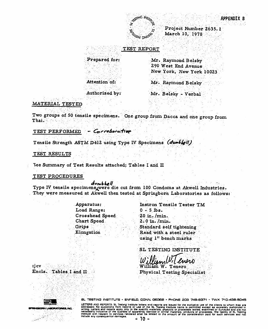

D 412
p-tce one end ofa dumbbell specimen in the 92 For exposure at any temperatureupper grip of the te-ting machine Remove above standard (see 91) condition Method A the loer grip from the machine andattach to specimens for 10 t 2 min and Method 1i the specimen To this lower grip attach a specimens for 6 2 min (Note 4) Place eaeh hook suitable for holding known masses Sus- specimen in the test chamber at interval pend a mass from the hook on the specimen ahead of testing so that all specimens of a in such a way (Note 3) as to permit the mass series will be in the test chamber the same assembly to rest on the machine grip holder length of time that is if 30 sis required to run If the machine has -4 the test A specimens the firstdynamometer head of for Method the compensating tjpe calibrate it at two or specimen placed in the test chamber 10 min more settings of the compensator Start the prior to testing would be followed by other motor and run as in normal testing until the specimens at 30 s intervals The conditioning mass assembly is freely suspended by the time at elevated temperature must be limited specimen If the dial or scale (whichever is to avoid additional curing or heat agingnormally used in testing) does not indicate NOTE 4 Caution-Suitable heat- or cold-reit the force applied (or its equivalent in stress ant gloves should be worn for hand and arm protwsfor compensating tester) within the specified tion hen testing ut high or low temperatures Athigh temperatures an air mask is very desirabletolerance thoroughly check the machine for hen the door of the chamber is opened to insert excess friction in the bearings and all other specimens toxic fumes may be present and shoul moving parts After eliminating as nearly as not be inhaled possible all the excess friction recalibrate the 93 For testing at sub-ambient temperaturemachine at a maximum of three points using condition the specimen at least 10 min priorknown masses to produce forces of approxi- to testingmately 10 20 and 50 of capacity The mass of the lower grip and hook shall be 10 Characteristics of Piece Tested included as part of the calibration mass If 101 The median of the values for three pawls and ratchet are used during test they specimens shall be taken as the characterishould also be used during the calibration tics of the piece of rubber tested except that Friction in the head can be checked by cali- under the following conditions the median of brating with the pawls up the values for five specimens shall be used
NOTE 3-It is advisable to provide a means for 10 11 Ifone or two values do not meet thepreventing the masses from falling to the floor in specified requirements when testing for comshycase the dumbbell should break pliance with specifications 82 A rapid and frequent approximate 1012 If referee tests are being made
check on accuracy ofthe tensile tester calibra METHOD A-DUMBBELL AND STRAIGht tion may be obtained by using a spring calibra SPECIMENS tion device 11 Apparatus
9 Test Temperature 1 1 Dies-The shapes and dimensions o 91conform dies for preparing dumbbell specimens shall
ard temperature for testing shall be 23 plusmn 2degC conform with those shown in Fig 2The 91 Unless otherwise specified the stand- withrthoeesshowniinFig 2aTdshy
(734 plusmn 360F) If the material is affected by inside faces inthe reduced section shall I moisture the relative humidity shall be main- polished and perpendicular -to the plane tained at 50 plusmnt 5and the specimen shall be formed by the cutting edges for a depth of at conditioned for at least 24 h prior to testing least 5 mm (02 in) The dies shall be sharpWhen testing at some other temperature is and free of nicks in order to prevent raggeId required the temperature specified shall be edges on the specimen one of those listed in Recommended Practice NOTE 5-Careful maintenance of die cuttiredges is of extreme importance and can be 0-D 1349 and the report shall include a state- tained by light daily honing and touching up thf ment of the temperature at which the test was cutting edges with jewelers hard honing stonlC made Specimens shall be conditioned for at The condition of the die may be judged by invei
gating the rupture point on any series of brtIcleast 3 h when the test temperature is23 specimens When broken specimens are remoNg21C from the clamps of the testing machine it isaduan
118
- 21
ta1eous to pile these specimens and note if there is any tendency to break at or near the same portionof each specimen Rupture points consistenhl oc-curring at the same place may be an indicatio6 thatthe die is dull nicked or bent at that particular position
112 Bench Marker having two paralleltraipht marking surfaces ground smooth in
the same plane The surfaces shall be be tween 005 and 008 mm (0002 and 0003 in)in width and at least 15 mm (06 in) in lengthThe angles between the marking surfaces andthe sides shall be at least 75 deg The distance between the centers of the marking surfaces -hall be within I 7 of the required distance
113 Ink Applicator having plane unyielding surface (for example hardwood plateglass or plastic) The ink shall have no deteri-orating effect on the specimen and shall be ofcontrasting color to that of the specimen
114 Grips-The tester shall have twogrips one of which shall be connected to thednamometer
1141 Grips for testing dumbbell speci mens shall tighten automatically and exert auniform pressure across the gripping sur-fces increasing as the tension increases inorder to prevent uneven slipping and to favorfailure of the specimen in its constricted section Constant-pressure pneumatic-type grips are also satisfactory If possible at the end of -nh grip a positioning device is recom
mended for inserting specimens to the same depth in the grip and aligning them with the direction of pull
1142 Grips for testing straight specimenshallbe either constant-pressure pneumaticAcdged or toggle type designed to transmit he applied force over a large surface area of he specimen 12 Prcparatin of Test Specimens
121 Dmnbbell Specilens-The piece of ubber to be tested shall whenever possiblee flat not less than 15 mm (0060 in) nor ire than 3 mm (0120 in) in thickness and
a size that will permit cutting a specimen ione of the standard methods If obtainedm a manufactured article the piece of rub-
r hall he free of surface roughness fabric i etc in accordance ith the proceWre described in Recommended Practice
)183 All specimens shall be cut so the
119
-
OD 412 lengthwise portion of the specimen will bcparallel with the grain unless otherwise specire with the g in th specifled with the exception that specimens oibelts wider than 300 mm (12 in) of shecel packing of hose or of dredging sleeves morethan 0 mm (4 in) in inside diameter shall be taken in the transverse direction In the caseof specially cured sheets prepared in accord ance with Recommended Practice of D 3182 the specimen shall be 20 t 02 mm ((080 = 0008 in) in thickness and died out in thedirection of the grain Dumbbell specimensshall conform in shape to those shown in Fig2 Unless otherwise specified Die C (Fig 2)shall be used to prepare the specimens In all cases the cutting of test specimens shall be done with asingle stroke of the cutting tool so as to assure obtaining smoothly cut surfaces
1211 Marking Dumbbell Specimens-Dumbbell specimens shall be marked withthe bench marker described in 112 The samshypIe shall be under no tension at the time it ismarked Marks shall be placed on the reshyduced section of the specimen equidistantfrom its center and perpendicular to its longishytudinal axis The distance between centers ofthe marks shall be ithin I of either 2500 plusmn 025 mm (or 100 = 001 in) on specimenscut with Dies C and D and either 5000 = 050 mm (or 200 plusmn 002 in) on specimens cut with the other dies shon in Fig 2 Benchmarks 20 mm (079 in) apart may he used to measure elongation where scales graduatedin millimetres are required
1212 Measuuring Dumbbell Specimns-Three measurements shall be made for thick ness one at the center and one at each end ofthe reduced section of the specimen The median of the three measurements shall beused as the thickness in calculating the crossshysectional area thatexcept specimens for which the differences between the maximum and minimum thickness exceeds 008 mm(0003 in) shall he discarded The idth of the specimen shall be taken as the distancebeteen the cutting edges of the die in the restricted section
122 StrsiL Specimens-Stright specishymen nnta) be prepared here it inot practishycal to cut either a dunibbell or t ring pectishymen is in the case of a narro rubber tripsmall tubing or electrical insulation These
- 22 shy
specimens ihall he of sufficient length it per-
rit their intallationi in the griprs used in the test Bench marks shall be placed on the specimens as described for dumbbell speci-mens in 1211 to determine the cross sec-tional area of stright specimens in the form of tubes the weightlength and density of the specimen may be determined The cross- sectional area may then be calculated from the measurements as follows
A - MIDL
where A = cross-sectional area A = mass ) = density and L - length
13 Procedure
131 Dtermination of Tensile Stress Ten-sile Strength and Ultimate Elongation-Place dumbbell or straight specimens in the grips of the testing machine usint care to adjust the specimen symmetrically in order that the tension will be distributed uniformly over the cross section If tension is greater on one side of the specimen than on the other the bench marks will not remain parallel and maximum strength of the rubber will not be developed Unless otherwise specificd the rate ofgrip separation shall be 85 t 08 mms (20 plusmn 2 inmin) (Note I) Start the machine and note continuously the distance between the two bench marks taking care to avoid parallax Record the stress at the elongation specified and at the time of rupture prefera-bly by means of an autographic or spark re-corder At rupture measure and record the elongation to the nearest 10 ron the scale
132 Determination of Tensile Set-Place the specimen in the grips of the testing appara-tus and adjust symmetrically so as to distrib-ute the tension uniformly over the cross sec-tion Separate the grips at a rate of speed as uniformly as practicable requiring about 15 s to reach the specified elongation Then hold the specimen at the specified elongation for 10 min release quickly without allowing it to snap back and allow to rest for 10 min At the end of the 10-min rest period measure the distance between the bench marks to the near-est I of the original length and calculate the tensile set In stretching the specimen it has
D 412 been found convenient to use a measured rod of a length equal to the exact distance re quired between the two bench marks Hold ing the rod behind the test specimen while it is being stretched simplifies the operation and reduces the chance of stretching the speci men more than the required amount Use a stop watch or equivalent timer for recording the time required for the various operations
133 Determination of Set at Break-Set at break is the set determined on the speci men when stretched to rupture Ten minutes after the specimen is broken fit the two pieces carefully together so that they are in contact over the full area of the break Mea ure the distance between the bench mark and calculate the set
14 Calculation
141 Calculate the tensile stress as follomi Tensile stress - FIA (11
F = observed force and A = cross-sectional area of the unstretched
specimen 142 Calculate the tensile strength by letshy
ting F in Eq I be equal to the force required to break the specimen Tensile stress and tensile strength are expressed in either megapascal or pounds-force per square inch
143 Calculate the elongation as follows
Elonation - [(L-Lo)L] x 100 121 where L = observed distance between the bench
marks on the stretched specimen and L = original distance between the bench
marks
144 Calculate the ultimate elongation b letting L in Eq 2 be equal to the distance between the bench marks at the time of rupshyture
145 Calculate the tensihk set by substilutshying the distance between the bench mark after the 10-min retraction period for L in F-4 2
METHOD f-CUT RING SPECIMENS
15 Apparatus 151 Specimens Cut from Flat Sheets 1511 Cutter-The cutter sh6wn inFig I
120
- 23 -
Qt) D412 irecommended The cutter is rotated by a gage set the blade depth as indicated in Figmachine having sufficient torque to mainlain 3 Be extremely careful that the blade alignshya pecd of at least 31 rads (300 rpm) during ment is good Place the cutter in position inculting and having precision bearings and the drill press and adjust the machine so thatpindle for holding the cutter with a maxi- the bottom of the blade holder is approxishymum run-out of 0010 mm (00004 in) The mately 13 mm (05 in) above the rubber slabmachine should have a base perpendicular to on the hold-down platethe spindle and preferably an arrangement 1612 Set the stop on the vertical travel sofor positioning the rubber piece with respect that the tips of the cutting blades just peneshyto the spindle trate the rubber piece Lower the cutter at a1512 Rubber Holding Devke-A vac- steady uniform rate until it reaches the stopvum holding plate similar to the one shown in then bring it back to its initial position BeFig 4is recommended The plate is clamped sure that when the blade holder is fully lowshyto the base or table of the cutting machine ered the bottom of the holder does not conshyother size plates may be used depending on tact the rubber For specimens that arehe size of the rubber piece The holding thicker than 225 mm t0090 in) the cuttingkvie has plane parallel upper and lower blades will have to be adjusted A mild soapbull rftaces and is connected to a source of solution for lubrication may be used onMcduced pressure to hold the rubber piece
the cutting blade hen cutting the ring specishyfirmly on the plate without distortion men
152 Specimens Cut from Tubes 162 Preparatioinfrom Tubes-The tube is1521 Cutter-A sharp knife edge or razor placed on a mandrel preferably slightlyHlade held firmly in the tool post ofa lathe larger than the inner diameter of the tube so it1522 Mandrel-A hard rubber or wood is held firmly The mandrel and tube are roshyindrcl to fit the tube hold andused to tated in a lathe and rings of desired width areate the rubber piece in the lathe cut Thin-aled rubber tubes that can be laid153 Testing Machine Grips-The assem- flat may be cut with dies having to parallel1t1hown in Fig 5 is recommended to ex- bladesend the ring The shaft is 475 mm (0187 in) 163 Ruhbcr Rings-Products in the formidiameter The surface of the shaft shouldN lubricated with
of rings are tested uithout special preparationa material that does not if their size permits testing in the tensilefct the rubber particularly for tests at ele- tester Such products include ring seals andtied temperatures rubber bands154 Cirviunfrrence Gages-A cone or 164 MeauriRin Specicns-The rashyum of acone may be used to measure the dial width is measured at three locations disshyde diameter of ring specimens and shall tributed around the circumference of the ringhe steps having diametric intervals not ex- using the micrometer as specified in 63 The-cding 2 of the diameter to be measured thickness of the disk cutlternatively for rings cut from the inside ofAith the cutter the ring is meaured with the micrometerho n in Fig 3 go-no-go gages may be used described in 63 The cross-sectional area is
calculated from the medians of three width16 Pre-paration of Test Specimens and three thickness measurements Alternashy161 The ring specimen shall be prepared lively to measuring the width and thicknesstom flat sheets not less than l() mm (004 the area may be determined from the massinI nor more than 30 mm (012 in) in thick- density and mean circumference of the ringand of a size that will permit cutting the NOTEUs 6-For ringof know ndensity and meanPecimen Ring specimens shall conform to circumference the meaurementthe dimensions shown in Fig 3 Unless other-or mass is more
rapid and reliable for determining area than dimenshyIc specified the Type I cut ring shall be sional meaiurncmefli cd 165 Rin CiruiIirence-Theinside cirshy1611 Place the blades in their proper slots cumtference of ring pecimens can be detershyin the holder and using the blade-seting mined by the stepped cone or gono-go gages
121
- 24 shy
dcicribed in 154 cmploing no strcs in ex-ce- of that neccsar to overcome any ellip-ticity of the ring The mean circunferenve is obtained by adding to the inside circumfer-ence the product of the radial idth and pi (314)
NOTE 7-Types i 2 and 3 ring specimens inFig 3are designed for autographic measurement ofclongation Trpe I ha an inside circumference of 2inso that spindle separation in inches equals theultimate elongation inpercent Type 2has ameancircumference of 1(1 mm so that each 50 mm ofgrip separation equals t r elongation Type 3haamean circumference of 4 inso that each 2inof grip separation equals 100)1 elongation
17 Procedure 171 LDterminatien o Tensile Stress Ten-
sile Strength and Ultimate Eongation NOTE 8-For materials having a yield point un-
der 20 11 elongation hen tested at 80 t 008 mms 420 = 2inimin) the rate shall be reduced to085 mmls t20 inmin) If the material still has asyield point under 20 r( elongation the rate shall bereduced to 0085 mms (020 inmin) The rate ofseparation shall be reported
17 11 Place the ring specimen around the lubricated spindles The initial setting beshytween the spindles from center to center shall be adjusted so that a minimum of tension is placed on the specimen prior to testing Un-less otherwise specified spindle separationshall be 8 = 08 mms (20 plusmn 2inmin) Start the test machine and record continuously the distance between the centers of the spindlesIf the stress and struin are not autographically recorded predetermine the distance between the centers of the spindles as prescribed in 174 for the elongation specified for the mate-rial under test
1712 Record the stress at the predeter-mined distance between the centers of the spindles and at the time of rupture preferablyby means of an autographic recorder At rup-lure measure the distance between the ceni-ters of spindles to within 25 mm (01 in) and record
18 Calculation 181 Calculate the tensile stress as follows
Tensile stresswhe s s F201where
F = observed force and 2A = twice the cross-sectional area
122
DI0412
182 Calculate the tensile strength by let ting F in the above equation flor tensile stre be equal to the force required to break the specimen
183 Calculate the ultimate elongation aN follows
E - 100 (2D + G - C)IC where E - ultimate elongation C = inside circumference of ring specimenD = distance between centers of the spin
dles and G = circumference of one spindle
184 Determine spindle separation for lon gation in determining the tensile stress at a specified elongation as follows
D = Ij(E3II00) + C - G1
where D = distance between spindle centers f1r
specified elongation andAl = mean circumference of ring specimen
19 Report
191 The report shall include the following1911 Results calculated in accordance
with Section 14 or 18 whichever is applicable
1912 Type of test specimen1913 Rate of extension if other than 8t
-t008 mms (20 -2 inmin)1914 Temperature and humidity of test
room if other than 23 plusmn 2degC and 50 plusmn 3pound
and 1915 Temperature of testing if other
than 23 t 2degC (734 plusmnt 360F) 192 In the case of a dispute or if referee
tests are being made the following item shall also be reported
1921 All observed and recorded data on which the calculations are based
1922 Type of testing machine 1923 Date of test and 1924 Date of vulcanization of the rubber
if known 20 PrecIsIon-Method A
reFsZATensile Stress Tensile Strength andUltimate Elongation (Note 9)-Column 3 Of Table I contains the coefficients of variation that have been estimated at aminimum of 61
- 25 shy
4I D412 degrees of freedom (DF) for the ranges of sin rather than in the single-operator precisionrroperty levels in Column 2 In Column 4 are 202 Tension Set and Set After BreMi the differences (ranges) that should be consid- (Note 10)-Column 3 of Table 2 contains thicred acceptable for two results These preci- coefficients of variation estimated for thi nn data are based on tests conducted exclu- ranges indicated in Column 2 of the proper1cly ith vulcanized sheets prepared by the ties listed in Column I In Column 4 are thttional Bureau of Standards differences (ranges) that should be consid
NOTE 9-These precision data are based on re- ered acceptable for two results The data artfrom 69(67 to72) laboratories 10 materials (9 testsult based on conducted with vulcanizetfr tensilestrcss) covering the range of properties sheets prepared by different laboratoriestdtulatcd above and short-term replication conshymitng of tests on 2 sheets of essentially the same NOTE 10-These precision data are approximamterial usually on the same day rather than on tions based on limited data from tests with 6 specicparatedays Therefore any day-to-day variabil- mens from each of 9 materials at 7 laboratoriesdue to differences in set-up etc over and The minimum degrees of freedom are estimated a^v the variability sheet-to-sheet on the same 76 and 10 for single-operator and multilaboratorlis largely reflected in the multilaboratory preci- precision rcspecttvely
TABLE I Precision or Tensile Strength Tensile Stress and Ultimate Elongation (Method A)
AcceptableCoefficient of Range ofProperty Applicable Range of Property Variation Two Results
of mean S q of mean D2S q
e-operator- (repeatability)Ienile strength from 165 to 320 MPa t24tX to 30 80
4600 psi)Icnile stress at 300 e elongation from 35 to 170 MP (0)0to 30 80 250W psi)thimate elongation from 450 to 740 f 30 704-adtllonatoryl reproducibility) 0 70
tensile strength from 165 to 320 MPi 4241MJto 110 160 4600 psi)lensile stress at 300 elongation from 55 to 170 NIPa 18Mt) 60to 170 2500 psi)t tinate elongation from 40 to 740 i 51 130
TABLE 2 Prclon c2Tension and permanent Set c~rnienof Acceptable
Mc~hodcoeffcient or Range ofTwo Re-Meihod Applicable Range I Variation of Ran -fof mean eshy S sult~ 3of mean
men S D2S 0orrrator (repeatability)Irmnanent set afterbreak from 4 to 1) II 11
from 11 to 1t 6 17from 19to32 5 13lension set from 2 to 7 8 23 from 8 to 17 3 1 from 8to26 3 T
bLItilaliratory (reproducibility)Ptmanent setafter break from 4 to 10 23 6
from Illtoi 14 44tcs from 19 to 32 1I 33Icnile set from 72to 311 92
from $to 17 17 53 from INto26 0 40
123
D 412
I1
I-
Zrr
~m
4
- gt
- - o
SPOOL IS LOOSE C 9 0eSHAFT AND SLOTTE
SHAFT WITH PINS-TO ENGAGE SPOOLS TO ENGAGE PIN WHC ACTS AS CLUTCH
FIG I Apparalm for Tealk Set Tos
124
- 27 -
D 412
30 a350~tH V f 0mm ApproxhLh
i 6mm Mi (Grind)
Spacer Is to 220
L T Enlarged Detail of Cutling EdgeSection T-T
I1-T II (Rod) A7
G (Rod)
2 Ailen-Head Bolts
I w
i f IThread This
I -D- Side of Die
Section X-X Dimensions or Standard Dumbbell )ie
I)imcn- Units Tolerance Die A Die B Die C Die D Die E Die F
mm 5 25 25 16 16 16in 004H mm max I I I 062 062 06240 40 40 M) 30 30in max 16 la 16C 12 12 12mm min 140 140 115 IIX) 121 125in min 5$ 5 45 4 q S1) mm 6 2 32 32 32 32 32in plusmnO256 12$ 125 1211 12 125I)-E mn plusmn1 129113 13 11 1T 13 13in 004
F mm z2 0 01 11 115 115 11538 31 19 19 8 31in plusmn008
6 mm 15 Li 07 4175 15 151 14 14 14 14 14 14in plusmn004 0 056) 056 056 016 0$6H mm t2 25 25 25 16 16 16in plusmn008 I I I 163 0)6 1163L m m plusmn2 9 13 9 19in plusmn008 232 232 131W mm 131 232 232+005 -O011111 12 6 h 3 3in +0112 -05111 (1M411 412s)
b112M) 11125 115 1-511
lie kisc dimenions are expreswed in metric unil are not itatelh the tmc tdichiwelliCd inUS cUStlmary unit Hoilic dimcmiln irecr equitlcnl reull m he ereeced from either die IMusi4 unitare intcnded for ue ilh d iw ed in-pparautu c rali-ratedin ntite unitI sd ued in clicking machineitiprcferahic lhat Ih hksnlI-11$ mil tit t1i 112i
I 2 Standard I)ivfrr utultlnIlumbllhi mnm
125
- 28 -
D 412
F C
I I I M I i
SI
I I tI I I
A 11618plusmn=00510637plusmn0O002 295 0 f1161 plusmn 0004 I 00 =01 ji18 l 000-4446 plusmn 01I 1756 =0B I02 plusmn 001 0040 _ 00007 20 plusmn 002i0079 plusmn 0001 20 plusmn 002j0079 plusmn 0001 |40 - 004]157= 0w2C IltA IltA ltA IltA I ltA I ltA ltCA IltCAD IOne-halfA dimension less halir of thickness oatcutting blade E jSum o4Band Ddimensions NOTr-TIe slot for the cutting blade must be positioned so the point is on the diameter perpendicular to the 2ut FubullBard-Parker blade No 1ISthe slot is 54 plusmn 0i mm wide 035 plusmn002 mm deep and offset from the enter line Inthe
direction of rotton by 17 ram
FiG 3 Rlng Cutter
Sr 126
- 29 -
DID412
75 10 95
gte -
I o o
I
Dimen Dimienslon mm in ion mm in
6 025A 178 70 E 13 02 6 0l F 19 7 5
9 35 G 23 090C 2H I 5 M M11D 229 9 0
IG 4 Valcuum Hlolding Plle
FIG $ A mhl Rir pT emnle T c-1IFillure
127
-30 - APPENDIX C-3
SA15NDA NS IASTM D 3577-77 151TANDAID
Standard Specification for RUBBER SURGICAL GLOVES
This Standard is issued under the fixed designation D 3577 the number immediately following the designation indicatesthe year of original adoption or in the case of revision the year of last revision A number in parentheses indicates the yearof Ias reapproval
I Scope 11 This specification describes certain
requirements for packaged sterile rubber surgical gloves used in conducting surgicalprocedures
2 Applicable Documents 21 ASTA Standards D412 Tests for Rubber Properties in Tenshy
sion D573 Test for Rubber Deterioration in an
Air Oven 22 Other Documents ISO 2859 Sampling Procedures and Tables
for Inspection by Attributest
3 Significance 31 The specification isintended as a refer-
ence to the performance and safety of rubber surgical gloves The safe and proper use of rubber surgical gloves is beyond the scope of this standard
4 Classification 41 Type -Gloves compounded primar-
ily from natural rubber latex 42 Type 2-Gloves compounded from a
rubber cement or from synthetic rubber latex
S Materials
51 Any rubber polymer compound that permits the glove to meet the requirements of this specification
52 A lubricant that meets the current re-quirements of The US lhartutipeillt for Absorbable Dusting Powder may be applied to the glove Other lubricants may be used iftheir safety and efficacy have been previously established
6 Sampling 61 For referee purposes gloves shall be
sampled and inspected in accordance with ISO 2859 The inspection levels and acceptashyble quality levels (AQL) shall conform to those specified in Table 3 or as agreed beshytween the purchaser and the seller if the latshyter is more comprehensive
7 Performance 71 Gloves sampled in accordance with
Section 6 shall meet the following requireshyments
711 Comply with requirements for sterilshyity when tested in accordance with 82
712 Be airtight when tested in accordshyance with 83
713 Have consistent physical dimensions in accordance with 84
714 Have acceptable physical property characteristics in accordance with 85 8 Referee Test Methods
81 The following tests shall be conducted to assure the requirements of Section 7 as prescribed in Table 3
82 Sterility Test-Testing for sterility shall be conducted in accordance with the latest edition of the US Pharmacopeia
IThis specification isunder the jurisdiction of ASTM Committee D-I I on Rubber and RubberLike Materials and isthe direct rcstmnsibiliky of Subcommittee Di 1411 onConsumer Ruhber ProductsCurrent edition approved April 25 1977 Published May 1977
Annual Book ofASTM Standards Part 373 Available from American National Standards Instllute 1430 Broadway New York NY 100184 US Pharmacopeia latest revision Muck PublishingCo Easton Pa 19175
497
-31 -
Q0h D3577 83 Airtight 7st- I loles in the glovc shall 8521 After being subjected to a temper
he detected hy fastening the cuff to a circular ature of 70 t 2degC for 166 t 2 h the tensilimandrel inflating with air to a gage pressure strength and ultimate elongation shall not bof L5 kPa and immersing in water at room lcss than the values specified in Table 1Thitemperature to a depth of 200 plusmn 10 mm method shall be the condition for referciabove the tip of the middle finger The infla- tests tion pressure shall be plusmn 10 and the immer- 8522 After being subjected to a tempersion time shall he 15 plusmn 05 min Emergence ature or I(m1(plusmn 2oC for 22 - 03 h the tensiltof air bubbles from the glove constitutes an strength and ultimate elongation shall not btairlight failure The mandrel shall have a di- less than the values specified in Table I ameter of 90 t I mm and a minimum mass of 15 kg The mandrel is bored for air passage 9 Acceplanceand tapped to accept a suitable 9(-deg pipe- 91 G lves will be conidered t) meet thc to-hose elbow adaptor The inflation appara- referee performance requirements when tesitus consists of the following pressure bulb re sults dornotrmanee r e qui re scrbe ldswith control valve tubing ( ito 5-kPa pressure Table od gage hose lee 90-deg elhow adaptor water tank and fatener The inflalion apparatus 92 Retests are permissible under te proshall be assembled by attaching three suitable visions of The US Pharmacopeia and ISO lengths of tubing to the hose tee Tubing from 2859 the tee leg is connected to the pressure bull)Tuhs from the other legs of the tee are con- 10 Packaging and Markingnceld to the pressure gage and the mandrel 101 Packaging
84 Phkysical Dimensinis Test 10311 The unit of packaging shall norshy841 The gloves shall comply with the di- mally be one pairof glovesmension requirements specified in Table 2 10 12 A pair of gloves normally shall be842 The length shall be expressed in mil- enclosed in an inner wallet or wrapper Thelinetres as measured front the tip of the sec- wrapper shall be of sufficient size whenond finger io the outside edge of the cuff opened to provide a field for glove-donning
843 The width of the palm shall he cx- purposespressed in millimctres as measured at a level 1013 The pair and accompanying wrpshybetween the base of the index finger and the per if utilized shall be totally enclosed in anbase of the thumb Values of width per size outer package that will allow sterilization of other than listed shall meet the stated toler- the product ance specified in Table 2 11114 The outer package shall have a844 The minimum thickness shall be cx- method of closure sufficient to assure the steshypressed in millimetres as specified in Table 2 rility of tile product until opened or damagedwhen using a dial micrometer described in 1115 The outer package shall have suffi-Methods D 412 and in Ile locations indicated cient strength and integrity to withstand norshyon Fig I For referee tests cutting the glove mal transportation and storage within the inshyis necessary to obtain single-thickness ineas- terniediate or shipping cartons or bothurenlents 1(016 The method of closure of the outer85 Physical Requirements Test package shall be such that prior opening will
851 Before and after accelerated aging be detectable by the userthe gloves shall conform to the physical re- 1017 None of tie packaging materialquirements specified in Table I Tests shall be shall contain any material likely to impair theconducted in accordance with Methods quality and use of the glovesD 412 1018 Intermediate cartons and shipping
852 Accelerated aging tests shall be con- cases shall be of sufficient strength to maintaindueted in accordance with Method D 573 the quality and sterility of the product duringTest the gloves by either one of the following normal transportation and storagemethods 1(12 Marking
498
-32-
D 3577
1021 Cilovcs shall have n appropriat mantufacturing lot number marking or he color-coded to designate sie 1(24 The outermost case shall be labeled
It022 Inner wrappers or wallet if uti- on one or morc end panels with the glove size lized shall hear a size marking t) be located the legend sterile and a manufacturing lot on the outside of the wallet Jr wrapper number
1023 Packages shall bear markings for 1025 All levels of packaging shall conshythe contents to include the glove size instruc- form to till appropriate government labeling tions for opening the legend sterile and a regulations
TABLE 1 Physical Requlrements
Before Aging After Accelerated Aging
Type Tensile Ultimate Ehon- Stres ul 500 Elongatiin Tensile Ultimate Elhn Strength gation Strength gatin
1 24 MPa min 750 min 55 MPa max I8 MPa min 560t min
It 17 MPa min 650 min 70 MPa max 12 MPa iun 490 min
TABLE 2 Dimensions and Tolerances
Size Designation Shs 6 6I 7 7 8 tt 9
Tolerance
Length mm 245 265 265 265 265 265 265 265 min
Width mm 70 76 83 19 95 1(12 10 114 t6
Thickness mm Finger Palm
01() 010
min min
Cuff 0 101 min
TABLE 3 Performance Requirements in pectlon AOL
Characteristic Related Defects Level
Sterility fails sterility ANA
Airtight holes S-4 25
Physical dimensions length width and thickness 5-2 40
Physical properties before aging after accelerated aging S-2 40
A See U S Pharmacapeia
499
- 33 -
O3577
A Finger Tip
istance n
A 13 35 C 33 1 7 D 48 19 INote 11
1 25 1
C
NoteI - Dimension Dto locale oppronlmole center ofpalm with relpecl to glove size
Cull
- _- - Cult Edge
FIG I Location of Thickness Measurements
The American Sorielyfr Testing and Materialstakes no position respecting the validityofany patent rihs asserted inionnecllon with any item mentioned in this standard Users elf this standard are exrssa ertofthe validity f any such patent rights and the risk ofinfringement ofsuch rights Isentirely their own responsIbility
500
BS 3704 September 1972 UDC 013888 61547788
APPENDIX D
34 shy
-- -- f- I 2 ---- -- - -
Specification for
Rubber condoms
Amendments issued since publication
kmamp No Date of issue Text affected
BritishStandards Institution 7 2 Park Street London WIA 2BS Telephone 01 -629 9000 Telex 266933
BS 37041972 - 35 -
Foreword The first edition of BS 3704 was published in 1964 as a result of a proposal made by The Family Plannin iAssociation (FPA) following which BSI held a representative conference at which It was decided that standardL dealing with contraceptive appliances in terms of the approved list of appliances published by FPA should be prepared This work was conducted under the authority of the BSI Surgical Instruments and Medical AppliancelIndustry Standards Committee BS 3704 as published in 1964 was one of the first standardsdealing wltd contraceptive appliances issued by national standardizing bodies and since that time the importance ofqualitycontrol in this field has been recognized in other countries by the issue of relevant specifications
In the Foreword to BS 3704 1964 it was stated that the Technical Committee established as a result of the initiating conference recognized that notwithstanding a sound system of quality control productonit was nol realistic to expect that condoms can be produced with each individual item free from holes or flaws as defined inthe standard As a result of improvement of manufacturing techniques it has now been found possible for qualitycontrol techniques based on cumulative sampling methods applied to continuous productionruns to ensure that defective products (as deiermined by the presence of holes) do not exceed 05 n continuous production in contrast to the limit of 10 tolerated in the previous edition of this standard Furthermore certain details of therequirements for the test for freedom from holes have made the test more stringent than that previously adoptedThe method specified for quality control for freedom from holes in this standaid is not however intended tcexclude utilization ofelectrolytic or other methods for the purposes of routine production control of all condomi produced as operated by the manufacturer as an additional safeguard
After review of the bursting strength test by filling with water as specified in the first edition together withthe possibility of adoption of an air inflation test it was considered that such tests had no special merit a3 supplementary to the water filling test for holes It was consequently decided that quality control could beusefully supplemented by tests for the tensile propetiles of the material bearing in mind the possibility of effects of lubricants and storage
The standard is one which Ismost useful to purchasers of large consignments from a given manufacturer it can however provide an equal level of confidence to purchasers of smaller quantities if the manufacturer Is licensed by the British Standards Institution to use Its registered certification trade mark because the BSI will ensure that its licensees operate a level of quality control sufficient to maintain the quality of their products at least equal to that defined in the standard Manufacturers are therefore Invited to apply for the right to use the BSIs certification mark and particulars may be obtained from the British Standards Institution MaylandsAvenue Hemel Hempstead Herts (see the inside back cover of this standard for information on BSIs certification nark scheme)
Condoms are packaged in a way which iormally will protect them during storage and for this purpose airtightindividual packs are to be recommended Nonetheless in Appendix C attention is drawn to simple precautionsaimed at maintaining quality after condoms have left the manufacturers works
2
BS 37041972 --36 -
British Standard Specification for
Rubber condoms
1 Scope This British Standard specifies requirements for condoms made of rubber latex Intended for single use NOTE 1 Any claims made for the efficacy of spermicidal or other dressing materials are excluded from the scope of this Bitlsh Standard NOTE 2 The titlesofBritish Standards referred to in this standard are listed on the Inside back covei
2 Materials Condoms shall be manufactured from good quality rubber latex
The condoms and any dressing materialapplied to them shall not liberate substances which are known to be toxic or otherwise harmful under normal conditionsof use Any dressing material shall not have a deleterious effect on the condom
3 Design 31 Sampling At least one specimen shall be taken at random from eachproducton quantlimnot exceeding 10 000 condoms 32 Rim The open end of the condom shall terminate in an integral rim 33 Length The length of the condom (excluding the teat if provided) shall be not less than 160 rm 34 Width The width of a condom when laid flat measured at any point up to 85 mm from the rim shall be not less than 49 mm and not more than 56 mm
For condoms having a shaped profile about the closed end the width of such profile when laid flat shall be not more than 70 mm
35 Thickness The doublewall thickness determined with a micrometer dial gauge graduated in intervals of 001 mm and complying with the requirements of BS 903 Part A2 of a condom measured Inthe region 80 mm from the open end shall be not more than 016 nun
Specimens which are lubricated shall prior to the measurement of thickness have the lubricant removed as described in36 36 Weight The weight of each specimen determined on a balance of suitable accuracy shall be not mori than 170 gSpecimens which are lubricated shall prior to weighing have the lubricant removed by means ofwater or of propan-2-ol in accordance with BS 1595 fsoPropyl alcohol followed by drying to constant weight
Freedom from holes 41 Simpling At least 100 specimens shall be taken at random from eachproduction quanturnot exceeding10 000 condoms 42Method of test The specimens constituting the test sample shall be tested for freedom from holes as evidenced by absence of leakage when filled with 300 ml of water and firmly rolled over absorbent paper in accordance with Appendix ASpecimens subjected to this test shall be destroyed after test 43 Test requirements The number of condoms tested and the number of defective condoms from a sequenceof poduction quantl shall be recorded Te nu-ber-tdefective condoms from any one quantum shall not exceed 0004n + 5V1 i where
n = the number of condoms tested from each quantum The cumulative total of defective condoms from quanta
3
BS 37041972 - 37 shy
satisfying the above requirement shall not exceed O004N+ 5 66UTRO where N= the cumulative total ofcondoms tested from quanta satisfying that requirement at any point in the sequenceSuch cumulative assessmentshall continue for 1000 successive qtant of the same pioduitioi
Table I demonstrates the operation of the formula for cumulative sampling
Table 1 Sampling of condoms - freedom from holes
Quantum No Cumulhtive total of Cumulative number of test Cumulative totlof aUowable
condoms produced specimens N defectives
minimum Maxmum(o)(I10000 100 3 2 bull 20000 200 S 3 3000 300 6s 50000 Soo 8 80000 800 12 to Ioo ooi ooo 4 - I 10
100 10000010011000000 10000 711(00 10000000 100000 500
If thecumulative total of defectives exceeds the number of allowable defectives at any point in the sequenceof quanta the quantum at which this occurs shall be rejected The continued assessment of quality of furtherproduction quanta shall include all previous test results starting from quantum Number 1 and approval ofproduction shall be in suspense until the condition required by the scheme isagain fulfilled
5 Tensile PropertiesSt Sampling At least 10 specimens shall be taken at random from each successiveproductlon quantumjaotexceeding 400 000 condoms 52 Method of test The specimens constituting the test sample shall be tested for tensle properties inaccordance with Appendix B 53 Test requirements The mean tensile strength and elongation at break each calculated after excluding thelowest and highest of at least five test results shall comply with the following test requirements
Minimum Minimum tensile strength elongation at break
Sample tested less than 12 months after manufacture In the as-sampled condition 200 MPa lC 650
Sample tesied less than 12 months after manufacture and subjected to accelerated ageing 170 MPa bull 600
Sample tested 12 months or more after manufactureinthe as-sampled condition 170 MPa 600
Any quantum failing to satisfy these requirements shall be deemed not to comply with this British Standard
This formula permits the acceptance orup to 05 of defective products as defined by the presence ofholes (se4 when hea4on cumulative sampling methods applied to continuous production
SilPa- 10 NIms I Nmm2 I MPa is equivalent to s load of 10197 kllogams per square centimetre
4
BS 37041972 - 38 shy
6 Marking 61 Rubber condoms or the packages received by the consumer shall be legibly marked to include the followInj particulars
(I) The nane or trade mark of the manufacturer or vendor (2) The date (year and month) after which the article should not be used and which shall be not more thu
5years after manufacture or any lesser Interval agreed between the purchaser and the vendor (3) The number of this British Standard ie BS 3704
62 Instructions for use shall be included on or within each retail package
NOTE It isstongJly recommended that in view of the nature of this specification manufacturers and purchasing agencies shouldmake use of the certification mnrk scheme whereby the product may bear the registered certification mark of 1SIFor furtheiInformation see the Inside back cover of this standard 63 In the case of manufacturers licensed to use BSIs registered certlficatioztark BSI as the licensinjauthority shall have the right to check the validity of test results on prIluctlo ti by testing samples taken in the manufacturers works and from the manufacturers stores warehousesnd at points of sale on the openmarket Such samples shall include the pa prcoeduct
Appendix A
Test for holes
A1 Fit the specimen on the end of a suitable mount of about 45 mm diameter Suitable equipment Is illustrated nFIg l
A2 Ensure that the outer surface of the specimen Is in a dry state Then add 300 ml of water taking measures to ensure that air is expelled A3 After suspension for at least 3 minutes without visible leakage remove the specimen and close the open end firmly by twisting near the rim A4 Specimenswhiich have been treated ithiltbdcant-suring nianufacture should be rolled over a separatesheet-of absorbent paper in order to remove surplus lubricant before proceeding with the test given in AS AS Roll the specimen firmly under light pressure at least twice over a sheet of dry absorbent paper (preferal~lycoloured to avoid eye strain) and then inspect the alsorbent paper for signs of leakage A6 Condoms presenting visual evidence of leakage as described in A3 or AS shall be deemed to be defective
Appendix B
Tests for tensa properties
B1 Apparatus The following apparatus is required(1) Cutting die consisting of two parallel knives 20 mm apart set in a press abova a auliguig UULU zMPU UL
plastics material The length of the cutting edge of each knife shall be not less than 70 m (2) Tensile tcsting machine in accordance with BS 903 Part A2 with the following equipment and capability
a The normal sample clamps replaced by 15 mm diameter rollers one free to move on a bearing and the other rotated by a small electiic motor at about 7 revmin
b A load range of O-100 N A tolier separation speed of 500 mmmin
d Automaticrecording of the exact separation distance of the rollers and of the load during test B2 Preparation of sample specimens B21 At least 10 specimens shall be taken at random from each quantum as defined in 51 B22 Samplcs tested within 12 months of manufacture shall be divided into two equal parts (minimum five eich) One parL shall be subjected to accelerated ageing In the rolled condition with lubricant ifprovided each specimen being packaged as intended for supply to the consumer Accelerated ageing shall be undertaken by the air oven method In accordance with BS 903 Part A19 at a temperature of 700 C for 12 hours after which the specimens shall be taken from the oven and be allowed to cool in air for not less than 12 hours whilst remaining in the packaged condition
The second part of the sample shall not be subjected to accelerated agegin and shall be tested in the as-sampled condition
5
BS 37041972 - 39 shy
B23 Samples which are tested 12 months or more after manufacture shall not be subjected to accelerated ageing and shall be tested in the as-sampled condition bull B24 The test specimen shall be laid flat with its length at right angles to the cutting edges of the die and the test piece shall be obtained from a region 80 mm from the open end by cutting with one stroke of the press Onlytest pieces which have been completely separated at the first attempt shall be used The test piece shall be carefully wiped with a minimal quantity of propan-2-ol In accordance with BS 159S to remove any dressing material B3 Method of test Determine the mean single wall thickness of the test piece by measurement at notless than four equidistant points around the ring
Dust the sample with talcum powder lay it flat and measure the distance between the two folded edges The dimension of the perimeter used in calculation Is twice this measurement -
Place ring over the rollers and stretch it until it breaks Measure the load at break and final separation distance (between centres of the rollers) -A set of at least five test pieces shall be tested in this way for the calculation of the tensile strength as defined
in B4 B4 Calculation of results B41 The tensile strength of each test piece Iscalculated using the formula
FT= 2wt where- Tis the tensile strength (MPa)
Fis the breaking load (N) w is the width of the test piece (Ie 20 mm)
and t is the single wall thickness of the test piece (mm) B42 The elongation at break of each test piece Iscalculated using the formula
Eldngation at break = k + 2(final distance between rollers) -original perimeter
original perimeterwhere k is the length of the test-piece (mm) in contact with the rollers and which equas 47 mm with rollers of
15 mm diameter B5 Recording of results The tensile strength and elongation at break shalt be expressed as the mean of the test results obtained excluding the highest and lowest test results obtained on the set of test pieces
Appendix C
Notes on the storage of condoms and the use of lubricants
CJ Storage Rubber tends to deteriorate with age particularly in the case of thin-walled articles Condoms arepackaged in a way which normally will protect them during storage Nonetheless they should not be kept in stock longer than is necessary especially in warm climates The articles should be stored in a cool place and should be kept in containers such that the contents will not be subjected to mechanical damage As soon as anycondom shows any deterioration of the characteristics of the rubber it should be destroyed
The articles should not at any time be allowed to come into contact with oil based antlseptic phenols andtheir derivatives petroleum based grease petroleum spirit paraffin (kerosine) and other related organic productssince all these materials are extremely harmful to rubber
Reference may also be made to BS 3574 C2 Lubricants Because of the deleterious effect of oil and petroleum based grease including petroleunjellythese materials should not be used to lubricate condoms made of rubber A water soluble base lubricant or other lubricant having no harmful effect on rubber should be employed
- 40 -
L Elongate to give pressureI head ifrequired
f- Diameter about 45 Intl)
IJTJ
19M Rubber ring
SWell rouhded edgo
-Specimen
Distance to platform about 200 mm
Fig 1 Suitable mount for use in the test for freedom from hu
SI 7
- - - - -- -------------------------------
AMD 1766 June 1975
AMO 1768June 1975Junbull17bull
-
26 41 1 s 2AMD 1766
Amendment Slip No1 published 2 June 1975
to BS 3704 1972
Rubber condoms
Revised text
New clause Insert the following new clause immediately after clause 3
4 Freedom from visible defects 41 Sampling At least 100 specimens shall be taken at random from each productionquantum not exceeding 10 000 condoms These specimens shall subsequently be used for
testing for freedom from holes in accordance with clause 5 with the exception of those specimens exhibiting holes or tears 42 Method of test Specimens shall be examined by normal vision under good lightingconditions for any defects liable to cause failure in use Examination of the product shall be without significant stretchingNOTE Examples of such defects include visible holes tears broken or severely distorted rims particlesof foreigrn matter embedded in the film dirt of an oily nature lumps or surplus rubber bubblespermanent creases vith adhesion of the filn lesions resulting from abrasion or other surface dumuge
Those products found to be defective through the presence o holes or tears shall not he included in the assessment of visible defects but they shall be added to the number of defectives found when testing ror freedom from holes (see clause 5) All the remainingspecimens shall be tested for holes 43 Test requirements The results of testing for visible defects shall be evaluated In the sas-manner as the results of testing for freedom from holes (see clause 5) using the same formula for cumulative assessment and the same rejection procedure
Existing clause 4 Freedorn from holes bull Delete the tide of this clause subclauses 41 and 42 entirely and the first paragraph of
subclause 43 and substitute the following
5 Freedom from holes
51 Sampling See 41 52 Method of test With the exception of any specimen exhibiting visible holes or tears (see clause 4) the specimens constituting the test sample shall be tested for freedom from holes as evidenced by absence of leakage when filled with 300 ml of water and firmly tolled over absorbent paper in accordance with appendix A Specimens subjected to this test shall be destroyed after test 53 Test requirements The number of condoms tested and the number of defective condomsincluding those exhibiting visible holes and tears (see clause 4) from a sequence of production quantashall be recorded
- - -- - -- -----------------------------------------------
--------- -- -- -- -- -- -- - ---- - --- ----- - --- ----------
-------------
-42-
AMD 1766 Existing clause 5 Tensile properties Jn1975 Renumber this clause as clause 6 and subclauses 5152 and S3 as 6162 and 63
respectively -
AMD 1763 New clause June 1975
Insert the following new clause immediately after the newly numbered clause 6 Tensile properties
7 Colour fastness 71 Sanpling At least 10 specimens shall be taken at random from each successive production quanium not exceeding 400 000 condoms 72 Method of test Each specimen shall be thoroughly wetted Inside and out with tap water No attempt shall be made to remove any dressing material Each wet specimen shall be separately wrapped in white absorbent paper so tharthe largest possible surface area o the specimen is In contact with the paper and the whole sealed in a suitable container to prevent loss of moisture After 16 hours at room temperature the absorbent paper shall be visually examined in natural daylight for any indication of staining 73 Test requirements When the specimens have been sampled and tested in accordance with 71 and 72 there shall be no indication of staining of the absorbent paper by any colouring agent present in the specimens
A10 1766 Existing clause 6 Marking Jibe 1975 Renumber this clause asclause 8 and subclauses 61 and 62 as 81 and 82 respectively
bull
AMD 1760 Appendix BTests for tensile properties June 197S B1 Apparatus
Delete Item (2)a and substitute the following
a The normal sample Clamps replaced by IS mm diameter rollers one free to move on a bull bearing and the other rotated at a constant speed of about 7 rmin (to equalize the strain on the ring during the test)
AND 1766 B21 Jun 1976 At the end of this sentence delete S1 and substitute 61
AMD 1766 G24 June 1975
Add the following after the word material at the end of the final sentence and allowed to dry for not less than 16 hours
AMD 1766 B3 Method of test June 1975
Add the following after the word ring at he end of the first paragraph using a micrometer dial gauge graduated in Intervals of not more than 0002 mm

D 412
I1
I-
Zrr
~m
4
- gt
- - o
SPOOL IS LOOSE C 9 0eSHAFT AND SLOTTE
SHAFT WITH PINS-TO ENGAGE SPOOLS TO ENGAGE PIN WHC ACTS AS CLUTCH
FIG I Apparalm for Tealk Set Tos
124
- 27 -
D 412
30 a350~tH V f 0mm ApproxhLh
i 6mm Mi (Grind)
Spacer Is to 220
L T Enlarged Detail of Cutling EdgeSection T-T
I1-T II (Rod) A7
G (Rod)
2 Ailen-Head Bolts
I w
i f IThread This
I -D- Side of Die
Section X-X Dimensions or Standard Dumbbell )ie
I)imcn- Units Tolerance Die A Die B Die C Die D Die E Die F
mm 5 25 25 16 16 16in 004H mm max I I I 062 062 06240 40 40 M) 30 30in max 16 la 16C 12 12 12mm min 140 140 115 IIX) 121 125in min 5$ 5 45 4 q S1) mm 6 2 32 32 32 32 32in plusmnO256 12$ 125 1211 12 125I)-E mn plusmn1 129113 13 11 1T 13 13in 004
F mm z2 0 01 11 115 115 11538 31 19 19 8 31in plusmn008
6 mm 15 Li 07 4175 15 151 14 14 14 14 14 14in plusmn004 0 056) 056 056 016 0$6H mm t2 25 25 25 16 16 16in plusmn008 I I I 163 0)6 1163L m m plusmn2 9 13 9 19in plusmn008 232 232 131W mm 131 232 232+005 -O011111 12 6 h 3 3in +0112 -05111 (1M411 412s)
b112M) 11125 115 1-511
lie kisc dimenions are expreswed in metric unil are not itatelh the tmc tdichiwelliCd inUS cUStlmary unit Hoilic dimcmiln irecr equitlcnl reull m he ereeced from either die IMusi4 unitare intcnded for ue ilh d iw ed in-pparautu c rali-ratedin ntite unitI sd ued in clicking machineitiprcferahic lhat Ih hksnlI-11$ mil tit t1i 112i
I 2 Standard I)ivfrr utultlnIlumbllhi mnm
125
- 28 -
D 412
F C
I I I M I i
SI
I I tI I I
A 11618plusmn=00510637plusmn0O002 295 0 f1161 plusmn 0004 I 00 =01 ji18 l 000-4446 plusmn 01I 1756 =0B I02 plusmn 001 0040 _ 00007 20 plusmn 002i0079 plusmn 0001 20 plusmn 002j0079 plusmn 0001 |40 - 004]157= 0w2C IltA IltA ltA IltA I ltA I ltA ltCA IltCAD IOne-halfA dimension less halir of thickness oatcutting blade E jSum o4Band Ddimensions NOTr-TIe slot for the cutting blade must be positioned so the point is on the diameter perpendicular to the 2ut FubullBard-Parker blade No 1ISthe slot is 54 plusmn 0i mm wide 035 plusmn002 mm deep and offset from the enter line Inthe
direction of rotton by 17 ram
FiG 3 Rlng Cutter
Sr 126
- 29 -
DID412
75 10 95
gte -
I o o
I
Dimen Dimienslon mm in ion mm in
6 025A 178 70 E 13 02 6 0l F 19 7 5
9 35 G 23 090C 2H I 5 M M11D 229 9 0
IG 4 Valcuum Hlolding Plle
FIG $ A mhl Rir pT emnle T c-1IFillure
127
-30 - APPENDIX C-3
SA15NDA NS IASTM D 3577-77 151TANDAID
Standard Specification for RUBBER SURGICAL GLOVES
This Standard is issued under the fixed designation D 3577 the number immediately following the designation indicatesthe year of original adoption or in the case of revision the year of last revision A number in parentheses indicates the yearof Ias reapproval
I Scope 11 This specification describes certain
requirements for packaged sterile rubber surgical gloves used in conducting surgicalprocedures
2 Applicable Documents 21 ASTA Standards D412 Tests for Rubber Properties in Tenshy
sion D573 Test for Rubber Deterioration in an
Air Oven 22 Other Documents ISO 2859 Sampling Procedures and Tables
for Inspection by Attributest
3 Significance 31 The specification isintended as a refer-
ence to the performance and safety of rubber surgical gloves The safe and proper use of rubber surgical gloves is beyond the scope of this standard
4 Classification 41 Type -Gloves compounded primar-
ily from natural rubber latex 42 Type 2-Gloves compounded from a
rubber cement or from synthetic rubber latex
S Materials
51 Any rubber polymer compound that permits the glove to meet the requirements of this specification
52 A lubricant that meets the current re-quirements of The US lhartutipeillt for Absorbable Dusting Powder may be applied to the glove Other lubricants may be used iftheir safety and efficacy have been previously established
6 Sampling 61 For referee purposes gloves shall be
sampled and inspected in accordance with ISO 2859 The inspection levels and acceptashyble quality levels (AQL) shall conform to those specified in Table 3 or as agreed beshytween the purchaser and the seller if the latshyter is more comprehensive
7 Performance 71 Gloves sampled in accordance with
Section 6 shall meet the following requireshyments
711 Comply with requirements for sterilshyity when tested in accordance with 82
712 Be airtight when tested in accordshyance with 83
713 Have consistent physical dimensions in accordance with 84
714 Have acceptable physical property characteristics in accordance with 85 8 Referee Test Methods
81 The following tests shall be conducted to assure the requirements of Section 7 as prescribed in Table 3
82 Sterility Test-Testing for sterility shall be conducted in accordance with the latest edition of the US Pharmacopeia
IThis specification isunder the jurisdiction of ASTM Committee D-I I on Rubber and RubberLike Materials and isthe direct rcstmnsibiliky of Subcommittee Di 1411 onConsumer Ruhber ProductsCurrent edition approved April 25 1977 Published May 1977
Annual Book ofASTM Standards Part 373 Available from American National Standards Instllute 1430 Broadway New York NY 100184 US Pharmacopeia latest revision Muck PublishingCo Easton Pa 19175
497
-31 -
Q0h D3577 83 Airtight 7st- I loles in the glovc shall 8521 After being subjected to a temper
he detected hy fastening the cuff to a circular ature of 70 t 2degC for 166 t 2 h the tensilimandrel inflating with air to a gage pressure strength and ultimate elongation shall not bof L5 kPa and immersing in water at room lcss than the values specified in Table 1Thitemperature to a depth of 200 plusmn 10 mm method shall be the condition for referciabove the tip of the middle finger The infla- tests tion pressure shall be plusmn 10 and the immer- 8522 After being subjected to a tempersion time shall he 15 plusmn 05 min Emergence ature or I(m1(plusmn 2oC for 22 - 03 h the tensiltof air bubbles from the glove constitutes an strength and ultimate elongation shall not btairlight failure The mandrel shall have a di- less than the values specified in Table I ameter of 90 t I mm and a minimum mass of 15 kg The mandrel is bored for air passage 9 Acceplanceand tapped to accept a suitable 9(-deg pipe- 91 G lves will be conidered t) meet thc to-hose elbow adaptor The inflation appara- referee performance requirements when tesitus consists of the following pressure bulb re sults dornotrmanee r e qui re scrbe ldswith control valve tubing ( ito 5-kPa pressure Table od gage hose lee 90-deg elhow adaptor water tank and fatener The inflalion apparatus 92 Retests are permissible under te proshall be assembled by attaching three suitable visions of The US Pharmacopeia and ISO lengths of tubing to the hose tee Tubing from 2859 the tee leg is connected to the pressure bull)Tuhs from the other legs of the tee are con- 10 Packaging and Markingnceld to the pressure gage and the mandrel 101 Packaging
84 Phkysical Dimensinis Test 10311 The unit of packaging shall norshy841 The gloves shall comply with the di- mally be one pairof glovesmension requirements specified in Table 2 10 12 A pair of gloves normally shall be842 The length shall be expressed in mil- enclosed in an inner wallet or wrapper Thelinetres as measured front the tip of the sec- wrapper shall be of sufficient size whenond finger io the outside edge of the cuff opened to provide a field for glove-donning
843 The width of the palm shall he cx- purposespressed in millimctres as measured at a level 1013 The pair and accompanying wrpshybetween the base of the index finger and the per if utilized shall be totally enclosed in anbase of the thumb Values of width per size outer package that will allow sterilization of other than listed shall meet the stated toler- the product ance specified in Table 2 11114 The outer package shall have a844 The minimum thickness shall be cx- method of closure sufficient to assure the steshypressed in millimetres as specified in Table 2 rility of tile product until opened or damagedwhen using a dial micrometer described in 1115 The outer package shall have suffi-Methods D 412 and in Ile locations indicated cient strength and integrity to withstand norshyon Fig I For referee tests cutting the glove mal transportation and storage within the inshyis necessary to obtain single-thickness ineas- terniediate or shipping cartons or bothurenlents 1(016 The method of closure of the outer85 Physical Requirements Test package shall be such that prior opening will
851 Before and after accelerated aging be detectable by the userthe gloves shall conform to the physical re- 1017 None of tie packaging materialquirements specified in Table I Tests shall be shall contain any material likely to impair theconducted in accordance with Methods quality and use of the glovesD 412 1018 Intermediate cartons and shipping
852 Accelerated aging tests shall be con- cases shall be of sufficient strength to maintaindueted in accordance with Method D 573 the quality and sterility of the product duringTest the gloves by either one of the following normal transportation and storagemethods 1(12 Marking
498
-32-
D 3577
1021 Cilovcs shall have n appropriat mantufacturing lot number marking or he color-coded to designate sie 1(24 The outermost case shall be labeled
It022 Inner wrappers or wallet if uti- on one or morc end panels with the glove size lized shall hear a size marking t) be located the legend sterile and a manufacturing lot on the outside of the wallet Jr wrapper number
1023 Packages shall bear markings for 1025 All levels of packaging shall conshythe contents to include the glove size instruc- form to till appropriate government labeling tions for opening the legend sterile and a regulations
TABLE 1 Physical Requlrements
Before Aging After Accelerated Aging
Type Tensile Ultimate Ehon- Stres ul 500 Elongatiin Tensile Ultimate Elhn Strength gation Strength gatin
1 24 MPa min 750 min 55 MPa max I8 MPa min 560t min
It 17 MPa min 650 min 70 MPa max 12 MPa iun 490 min
TABLE 2 Dimensions and Tolerances
Size Designation Shs 6 6I 7 7 8 tt 9
Tolerance
Length mm 245 265 265 265 265 265 265 265 min
Width mm 70 76 83 19 95 1(12 10 114 t6
Thickness mm Finger Palm
01() 010
min min
Cuff 0 101 min
TABLE 3 Performance Requirements in pectlon AOL
Characteristic Related Defects Level
Sterility fails sterility ANA
Airtight holes S-4 25
Physical dimensions length width and thickness 5-2 40
Physical properties before aging after accelerated aging S-2 40
A See U S Pharmacapeia
499
- 33 -
O3577
A Finger Tip
istance n
A 13 35 C 33 1 7 D 48 19 INote 11
1 25 1
C
NoteI - Dimension Dto locale oppronlmole center ofpalm with relpecl to glove size
Cull
- _- - Cult Edge
FIG I Location of Thickness Measurements
The American Sorielyfr Testing and Materialstakes no position respecting the validityofany patent rihs asserted inionnecllon with any item mentioned in this standard Users elf this standard are exrssa ertofthe validity f any such patent rights and the risk ofinfringement ofsuch rights Isentirely their own responsIbility
500
BS 3704 September 1972 UDC 013888 61547788
APPENDIX D
34 shy
-- -- f- I 2 ---- -- - -
Specification for
Rubber condoms
Amendments issued since publication
kmamp No Date of issue Text affected
BritishStandards Institution 7 2 Park Street London WIA 2BS Telephone 01 -629 9000 Telex 266933
BS 37041972 - 35 -
Foreword The first edition of BS 3704 was published in 1964 as a result of a proposal made by The Family Plannin iAssociation (FPA) following which BSI held a representative conference at which It was decided that standardL dealing with contraceptive appliances in terms of the approved list of appliances published by FPA should be prepared This work was conducted under the authority of the BSI Surgical Instruments and Medical AppliancelIndustry Standards Committee BS 3704 as published in 1964 was one of the first standardsdealing wltd contraceptive appliances issued by national standardizing bodies and since that time the importance ofqualitycontrol in this field has been recognized in other countries by the issue of relevant specifications
In the Foreword to BS 3704 1964 it was stated that the Technical Committee established as a result of the initiating conference recognized that notwithstanding a sound system of quality control productonit was nol realistic to expect that condoms can be produced with each individual item free from holes or flaws as defined inthe standard As a result of improvement of manufacturing techniques it has now been found possible for qualitycontrol techniques based on cumulative sampling methods applied to continuous productionruns to ensure that defective products (as deiermined by the presence of holes) do not exceed 05 n continuous production in contrast to the limit of 10 tolerated in the previous edition of this standard Furthermore certain details of therequirements for the test for freedom from holes have made the test more stringent than that previously adoptedThe method specified for quality control for freedom from holes in this standaid is not however intended tcexclude utilization ofelectrolytic or other methods for the purposes of routine production control of all condomi produced as operated by the manufacturer as an additional safeguard
After review of the bursting strength test by filling with water as specified in the first edition together withthe possibility of adoption of an air inflation test it was considered that such tests had no special merit a3 supplementary to the water filling test for holes It was consequently decided that quality control could beusefully supplemented by tests for the tensile propetiles of the material bearing in mind the possibility of effects of lubricants and storage
The standard is one which Ismost useful to purchasers of large consignments from a given manufacturer it can however provide an equal level of confidence to purchasers of smaller quantities if the manufacturer Is licensed by the British Standards Institution to use Its registered certification trade mark because the BSI will ensure that its licensees operate a level of quality control sufficient to maintain the quality of their products at least equal to that defined in the standard Manufacturers are therefore Invited to apply for the right to use the BSIs certification mark and particulars may be obtained from the British Standards Institution MaylandsAvenue Hemel Hempstead Herts (see the inside back cover of this standard for information on BSIs certification nark scheme)
Condoms are packaged in a way which iormally will protect them during storage and for this purpose airtightindividual packs are to be recommended Nonetheless in Appendix C attention is drawn to simple precautionsaimed at maintaining quality after condoms have left the manufacturers works
2
BS 37041972 --36 -
British Standard Specification for
Rubber condoms
1 Scope This British Standard specifies requirements for condoms made of rubber latex Intended for single use NOTE 1 Any claims made for the efficacy of spermicidal or other dressing materials are excluded from the scope of this Bitlsh Standard NOTE 2 The titlesofBritish Standards referred to in this standard are listed on the Inside back covei
2 Materials Condoms shall be manufactured from good quality rubber latex
The condoms and any dressing materialapplied to them shall not liberate substances which are known to be toxic or otherwise harmful under normal conditionsof use Any dressing material shall not have a deleterious effect on the condom
3 Design 31 Sampling At least one specimen shall be taken at random from eachproducton quantlimnot exceeding 10 000 condoms 32 Rim The open end of the condom shall terminate in an integral rim 33 Length The length of the condom (excluding the teat if provided) shall be not less than 160 rm 34 Width The width of a condom when laid flat measured at any point up to 85 mm from the rim shall be not less than 49 mm and not more than 56 mm
For condoms having a shaped profile about the closed end the width of such profile when laid flat shall be not more than 70 mm
35 Thickness The doublewall thickness determined with a micrometer dial gauge graduated in intervals of 001 mm and complying with the requirements of BS 903 Part A2 of a condom measured Inthe region 80 mm from the open end shall be not more than 016 nun
Specimens which are lubricated shall prior to the measurement of thickness have the lubricant removed as described in36 36 Weight The weight of each specimen determined on a balance of suitable accuracy shall be not mori than 170 gSpecimens which are lubricated shall prior to weighing have the lubricant removed by means ofwater or of propan-2-ol in accordance with BS 1595 fsoPropyl alcohol followed by drying to constant weight
Freedom from holes 41 Simpling At least 100 specimens shall be taken at random from eachproduction quanturnot exceeding10 000 condoms 42Method of test The specimens constituting the test sample shall be tested for freedom from holes as evidenced by absence of leakage when filled with 300 ml of water and firmly rolled over absorbent paper in accordance with Appendix ASpecimens subjected to this test shall be destroyed after test 43 Test requirements The number of condoms tested and the number of defective condoms from a sequenceof poduction quantl shall be recorded Te nu-ber-tdefective condoms from any one quantum shall not exceed 0004n + 5V1 i where
n = the number of condoms tested from each quantum The cumulative total of defective condoms from quanta
3
BS 37041972 - 37 shy
satisfying the above requirement shall not exceed O004N+ 5 66UTRO where N= the cumulative total ofcondoms tested from quanta satisfying that requirement at any point in the sequenceSuch cumulative assessmentshall continue for 1000 successive qtant of the same pioduitioi
Table I demonstrates the operation of the formula for cumulative sampling
Table 1 Sampling of condoms - freedom from holes
Quantum No Cumulhtive total of Cumulative number of test Cumulative totlof aUowable
condoms produced specimens N defectives
minimum Maxmum(o)(I10000 100 3 2 bull 20000 200 S 3 3000 300 6s 50000 Soo 8 80000 800 12 to Ioo ooi ooo 4 - I 10
100 10000010011000000 10000 711(00 10000000 100000 500
If thecumulative total of defectives exceeds the number of allowable defectives at any point in the sequenceof quanta the quantum at which this occurs shall be rejected The continued assessment of quality of furtherproduction quanta shall include all previous test results starting from quantum Number 1 and approval ofproduction shall be in suspense until the condition required by the scheme isagain fulfilled
5 Tensile PropertiesSt Sampling At least 10 specimens shall be taken at random from each successiveproductlon quantumjaotexceeding 400 000 condoms 52 Method of test The specimens constituting the test sample shall be tested for tensle properties inaccordance with Appendix B 53 Test requirements The mean tensile strength and elongation at break each calculated after excluding thelowest and highest of at least five test results shall comply with the following test requirements
Minimum Minimum tensile strength elongation at break
Sample tested less than 12 months after manufacture In the as-sampled condition 200 MPa lC 650
Sample tesied less than 12 months after manufacture and subjected to accelerated ageing 170 MPa bull 600
Sample tested 12 months or more after manufactureinthe as-sampled condition 170 MPa 600
Any quantum failing to satisfy these requirements shall be deemed not to comply with this British Standard
This formula permits the acceptance orup to 05 of defective products as defined by the presence ofholes (se4 when hea4on cumulative sampling methods applied to continuous production
SilPa- 10 NIms I Nmm2 I MPa is equivalent to s load of 10197 kllogams per square centimetre
4
BS 37041972 - 38 shy
6 Marking 61 Rubber condoms or the packages received by the consumer shall be legibly marked to include the followInj particulars
(I) The nane or trade mark of the manufacturer or vendor (2) The date (year and month) after which the article should not be used and which shall be not more thu
5years after manufacture or any lesser Interval agreed between the purchaser and the vendor (3) The number of this British Standard ie BS 3704
62 Instructions for use shall be included on or within each retail package
NOTE It isstongJly recommended that in view of the nature of this specification manufacturers and purchasing agencies shouldmake use of the certification mnrk scheme whereby the product may bear the registered certification mark of 1SIFor furtheiInformation see the Inside back cover of this standard 63 In the case of manufacturers licensed to use BSIs registered certlficatioztark BSI as the licensinjauthority shall have the right to check the validity of test results on prIluctlo ti by testing samples taken in the manufacturers works and from the manufacturers stores warehousesnd at points of sale on the openmarket Such samples shall include the pa prcoeduct
Appendix A
Test for holes
A1 Fit the specimen on the end of a suitable mount of about 45 mm diameter Suitable equipment Is illustrated nFIg l
A2 Ensure that the outer surface of the specimen Is in a dry state Then add 300 ml of water taking measures to ensure that air is expelled A3 After suspension for at least 3 minutes without visible leakage remove the specimen and close the open end firmly by twisting near the rim A4 Specimenswhiich have been treated ithiltbdcant-suring nianufacture should be rolled over a separatesheet-of absorbent paper in order to remove surplus lubricant before proceeding with the test given in AS AS Roll the specimen firmly under light pressure at least twice over a sheet of dry absorbent paper (preferal~lycoloured to avoid eye strain) and then inspect the alsorbent paper for signs of leakage A6 Condoms presenting visual evidence of leakage as described in A3 or AS shall be deemed to be defective
Appendix B
Tests for tensa properties
B1 Apparatus The following apparatus is required(1) Cutting die consisting of two parallel knives 20 mm apart set in a press abova a auliguig UULU zMPU UL
plastics material The length of the cutting edge of each knife shall be not less than 70 m (2) Tensile tcsting machine in accordance with BS 903 Part A2 with the following equipment and capability
a The normal sample clamps replaced by 15 mm diameter rollers one free to move on a bearing and the other rotated by a small electiic motor at about 7 revmin
b A load range of O-100 N A tolier separation speed of 500 mmmin
d Automaticrecording of the exact separation distance of the rollers and of the load during test B2 Preparation of sample specimens B21 At least 10 specimens shall be taken at random from each quantum as defined in 51 B22 Samplcs tested within 12 months of manufacture shall be divided into two equal parts (minimum five eich) One parL shall be subjected to accelerated ageing In the rolled condition with lubricant ifprovided each specimen being packaged as intended for supply to the consumer Accelerated ageing shall be undertaken by the air oven method In accordance with BS 903 Part A19 at a temperature of 700 C for 12 hours after which the specimens shall be taken from the oven and be allowed to cool in air for not less than 12 hours whilst remaining in the packaged condition
The second part of the sample shall not be subjected to accelerated agegin and shall be tested in the as-sampled condition
5
BS 37041972 - 39 shy
B23 Samples which are tested 12 months or more after manufacture shall not be subjected to accelerated ageing and shall be tested in the as-sampled condition bull B24 The test specimen shall be laid flat with its length at right angles to the cutting edges of the die and the test piece shall be obtained from a region 80 mm from the open end by cutting with one stroke of the press Onlytest pieces which have been completely separated at the first attempt shall be used The test piece shall be carefully wiped with a minimal quantity of propan-2-ol In accordance with BS 159S to remove any dressing material B3 Method of test Determine the mean single wall thickness of the test piece by measurement at notless than four equidistant points around the ring
Dust the sample with talcum powder lay it flat and measure the distance between the two folded edges The dimension of the perimeter used in calculation Is twice this measurement -
Place ring over the rollers and stretch it until it breaks Measure the load at break and final separation distance (between centres of the rollers) -A set of at least five test pieces shall be tested in this way for the calculation of the tensile strength as defined
in B4 B4 Calculation of results B41 The tensile strength of each test piece Iscalculated using the formula
FT= 2wt where- Tis the tensile strength (MPa)
Fis the breaking load (N) w is the width of the test piece (Ie 20 mm)
and t is the single wall thickness of the test piece (mm) B42 The elongation at break of each test piece Iscalculated using the formula
Eldngation at break = k + 2(final distance between rollers) -original perimeter
original perimeterwhere k is the length of the test-piece (mm) in contact with the rollers and which equas 47 mm with rollers of
15 mm diameter B5 Recording of results The tensile strength and elongation at break shalt be expressed as the mean of the test results obtained excluding the highest and lowest test results obtained on the set of test pieces
Appendix C
Notes on the storage of condoms and the use of lubricants
CJ Storage Rubber tends to deteriorate with age particularly in the case of thin-walled articles Condoms arepackaged in a way which normally will protect them during storage Nonetheless they should not be kept in stock longer than is necessary especially in warm climates The articles should be stored in a cool place and should be kept in containers such that the contents will not be subjected to mechanical damage As soon as anycondom shows any deterioration of the characteristics of the rubber it should be destroyed
The articles should not at any time be allowed to come into contact with oil based antlseptic phenols andtheir derivatives petroleum based grease petroleum spirit paraffin (kerosine) and other related organic productssince all these materials are extremely harmful to rubber
Reference may also be made to BS 3574 C2 Lubricants Because of the deleterious effect of oil and petroleum based grease including petroleunjellythese materials should not be used to lubricate condoms made of rubber A water soluble base lubricant or other lubricant having no harmful effect on rubber should be employed
- 40 -
L Elongate to give pressureI head ifrequired
f- Diameter about 45 Intl)
IJTJ
19M Rubber ring
SWell rouhded edgo
-Specimen
Distance to platform about 200 mm
Fig 1 Suitable mount for use in the test for freedom from hu
SI 7
- - - - -- -------------------------------
AMD 1766 June 1975
AMO 1768June 1975Junbull17bull
-
26 41 1 s 2AMD 1766
Amendment Slip No1 published 2 June 1975
to BS 3704 1972
Rubber condoms
Revised text
New clause Insert the following new clause immediately after clause 3
4 Freedom from visible defects 41 Sampling At least 100 specimens shall be taken at random from each productionquantum not exceeding 10 000 condoms These specimens shall subsequently be used for
testing for freedom from holes in accordance with clause 5 with the exception of those specimens exhibiting holes or tears 42 Method of test Specimens shall be examined by normal vision under good lightingconditions for any defects liable to cause failure in use Examination of the product shall be without significant stretchingNOTE Examples of such defects include visible holes tears broken or severely distorted rims particlesof foreigrn matter embedded in the film dirt of an oily nature lumps or surplus rubber bubblespermanent creases vith adhesion of the filn lesions resulting from abrasion or other surface dumuge
Those products found to be defective through the presence o holes or tears shall not he included in the assessment of visible defects but they shall be added to the number of defectives found when testing ror freedom from holes (see clause 5) All the remainingspecimens shall be tested for holes 43 Test requirements The results of testing for visible defects shall be evaluated In the sas-manner as the results of testing for freedom from holes (see clause 5) using the same formula for cumulative assessment and the same rejection procedure
Existing clause 4 Freedorn from holes bull Delete the tide of this clause subclauses 41 and 42 entirely and the first paragraph of
subclause 43 and substitute the following
5 Freedom from holes
51 Sampling See 41 52 Method of test With the exception of any specimen exhibiting visible holes or tears (see clause 4) the specimens constituting the test sample shall be tested for freedom from holes as evidenced by absence of leakage when filled with 300 ml of water and firmly tolled over absorbent paper in accordance with appendix A Specimens subjected to this test shall be destroyed after test 53 Test requirements The number of condoms tested and the number of defective condomsincluding those exhibiting visible holes and tears (see clause 4) from a sequence of production quantashall be recorded
- - -- - -- -----------------------------------------------
--------- -- -- -- -- -- -- - ---- - --- ----- - --- ----------
-------------
-42-
AMD 1766 Existing clause 5 Tensile properties Jn1975 Renumber this clause as clause 6 and subclauses 5152 and S3 as 6162 and 63
respectively -
AMD 1763 New clause June 1975
Insert the following new clause immediately after the newly numbered clause 6 Tensile properties
7 Colour fastness 71 Sanpling At least 10 specimens shall be taken at random from each successive production quanium not exceeding 400 000 condoms 72 Method of test Each specimen shall be thoroughly wetted Inside and out with tap water No attempt shall be made to remove any dressing material Each wet specimen shall be separately wrapped in white absorbent paper so tharthe largest possible surface area o the specimen is In contact with the paper and the whole sealed in a suitable container to prevent loss of moisture After 16 hours at room temperature the absorbent paper shall be visually examined in natural daylight for any indication of staining 73 Test requirements When the specimens have been sampled and tested in accordance with 71 and 72 there shall be no indication of staining of the absorbent paper by any colouring agent present in the specimens
A10 1766 Existing clause 6 Marking Jibe 1975 Renumber this clause asclause 8 and subclauses 61 and 62 as 81 and 82 respectively
bull
AMD 1760 Appendix BTests for tensile properties June 197S B1 Apparatus
Delete Item (2)a and substitute the following
a The normal sample Clamps replaced by IS mm diameter rollers one free to move on a bull bearing and the other rotated at a constant speed of about 7 rmin (to equalize the strain on the ring during the test)
AND 1766 B21 Jun 1976 At the end of this sentence delete S1 and substitute 61
AMD 1766 G24 June 1975
Add the following after the word material at the end of the final sentence and allowed to dry for not less than 16 hours
AMD 1766 B3 Method of test June 1975
Add the following after the word ring at he end of the first paragraph using a micrometer dial gauge graduated in Intervals of not more than 0002 mm


