Data SheetDecember 1999
MC010-Series Power Modules:18 Vdc to 36 Vdc Input; 10 W
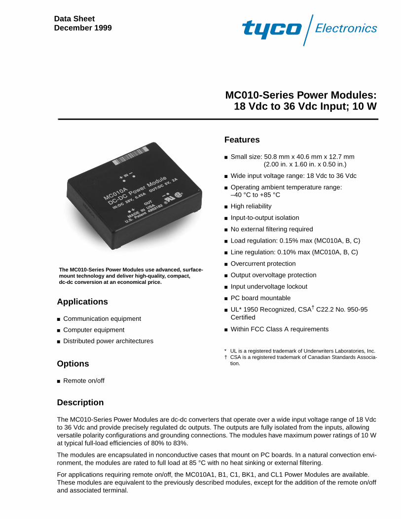
The MC010-Series Power Modules use advanced, surface-mount technology and deliver high-quality, compact, dc-dc conversion at an economical price.
Applications
Communication equipment
Computer equipment
Distributed power architectures
Options
Remote on/off
Features
Small size: 50.8 mm x 40.6 mm x 12.7 mm(2.00 in. x 1.60 in. x 0.50 in.)
Wide input voltage range: 18 Vdc to 36 Vdc
Operating ambient temperature range: –40 °C to +85 °C
High reliability
Input-to-output isolation
No external filtering required
Load regulation: 0.15% max (MC010A, B, C)
Line regulation: 0.10% max (MC010A, B, C)
Overcurrent protection
Output overvoltage protection
Input undervoltage lockout
PC board mountable
UL* 1950 Recognized, CSA† C22.2 No. 950-95 Certified
Within FCC Class A requirements
* UL is a registered trademark of Underwriters Laboratories, Inc.† CSA is a registered trademark of Canadian Standards Associa-
tion.
Description
The MC010-Series Power Modules are dc-dc converters that operate over a wide input voltage range of 18 Vdc to 36 Vdc and provide precisely regulated dc outputs. The outputs are fully isolated from the inputs, allowing versatile polarity configurations and grounding connections. The modules have maximum power ratings of 10 W at typical full-load efficiencies of 80% to 83%.
The modules are encapsulated in nonconductive cases that mount on PC boards. In a natural convection envi-ronment, the modules are rated to full load at 85 °C with no heat sinking or external filtering.
For applications requiring remote on/off, the MC010A1, B1, C1, BK1, and CL1 Power Modules are available. These modules are equivalent to the previously described modules, except for the addition of the remote on/off and associated terminal.
Data SheetDecember 199918 Vdc to 36 Vdc Input; 10 W
MC010-Series Power Modules:
2 Tyco Electronics Corp.
Absolute Maximum Ratings
Stresses in excess of the absolute maximum ratings can cause permanent damage to the device. These are abso-lute stress ratings only. Functional operation of the device is not implied at these or any other conditions in excess of those given in the operations sections of the data sheet. Exposure to absolute maximum ratings for extended periods can adversely affect device reliability.
Electrical Specifications
Unless otherwise indicated, specifications apply to all devices over all operating input voltage, resistive load, and temperature conditions.
Table 1. Input Specifications
Fusing Considerations
CAUTION: This power module is not internally fused. An input line fuse must always be used.
This encapsulated power module can be used in a wide variety of applications, ranging from simple stand-alone operation to an integrated part of a sophisticated power architecture. To preserve maximum flexibility, internal fus-ing is not included; however, to achieve maximum safety and system protection, always use an input line fuse. The safety agencies require a normal-blow fuse with a maximum rating of 5 A in series with the input (see Safety Con-siderations section). Based on the information provided in this data sheet on inrush energy and maximum dc input current, the same type of fuse with a lower rating can be used. However, for UL recognition, the dc rating of the fuse must not exceed 5 A. Refer to the fuse manufacturer’s data for further information.
Parameter Device Symbol Min Max Unit
Input Voltage:ContinuousTransient (ð1 second)
AllAll
VI
VI, trans
——
3647
VdcV
Operating Ambient Temperature(At 0.3 ms–1 (60 ft./min.) natural convection; see Thermal Considerations section.)
All TA –40 85 °C
Storage Temperature All Tstg –40 100 °C
I/O Isolation Voltage (1 minute) All — — 500 Vdc
Parameter Symbol Min Typ Max Unit
Operating Input Voltage VI 18 28 36 Vdc
Maximum Input Current (VI = 0 V to 36 V; IO = IO, max)
II, max — — 1.20 A
Inrush Transient i2t — 0.1 0.4 A2s
Input Reflected-ripple Current, Peak-to-peak(5 Hz to 20 MHz, 12 µH source impedance; TA = 25 °C; see Figure 1 and Design Considerations section.)
II — 25 — mAp-p
Input Ripple Rejection (120 Hz) — — 44 — dB
Input Inductance(see Design Considerations section.)
— — — 12 µH
Data SheetDecember 1999 18 Vdc to 36 Vdc Input; 10 W
MC010-Series Power Modules:
Electrical Specifications (continued)
Table 2. Output Specifications
Parameter Device Symbol Min Typ Max Unit
Output Voltage Set Point(VI = 28 V; IO = IO, max; TA = 25 °C)
MC010AMC010BMC010C
MC010BK
MC010CL
VO, set
VO, set
VO, set
VO1, set
VO2, set
VO1, set
VO2, set
4.8511.5214.411.4–11.414.25–14.25
5.012.015.012.0–12.015.0–15.0
5.2012.4815.612.6–12.615.75
–15.75
VdcVdcVdcVdcVdcVdcVdc
Output Voltage (Over all operating input voltage, resistive load, and temperature conditions until end of life. See Figures 3 and 4.)
MC010AMC010BMC010C
MC010BK
MC010CL
VO
VO
VO
VO1
VO2
VO1
VO2
4.8011.414.2510.08–10.0813.5–13.5
———————
5.2512.615.7513.2–13.216.5–16.5
VdcVdcVdcVdcVdcVdcVdc
Output Regulation:Line (VI = 18 Vdc to 36 Vdc)Load (IO = IO, min to IO, max)Temperature (TA = –40 °C to +85 °C)
MC010A, B, CMC010A, B, C
MC010AMC010BMC010C
—————
—————
0.020.05153545
0.100.1570150190
%VO
%VO
mVmVmV
Output Ripple and Noise Voltage(With 0.1 µF ceramic bypass capacitor on output; see Figure 2.):RMS
Peak-to-peak (5 Hz to 20 MHz)
MC010AMC010B, C
MC010BK, CLMC010A
MC010B, CMC010BK, CL
——————
——————
——————
10152070100100
mVrmsmVrmsmVrmsmVp-pmVp-pmVp-p
Output Current(At IO < IO, min, the modules may exceed output ripple specifications and dual-output modules may exceed specified output voltages.)
MC010AMC010BMC010C
MC010BK
MC010CL
IOIOIOIO1
IO2
IO1
IO2
0.10.040.030.040.040.030.03
———————
2.00.830.670.420.420.330.33
AAAAAAA
Output Current-limit Inception:VO = 4.5 VVO = 10.8 VVO = 13.5 VVO1 or VO2 = 10.2 VVO1 or VO2 = 12.75 V
MC010AMC010BMC010C
MC010BKMC010CL
IOIOIOIOIO
—————
3.71.51.31.41.3
5.52.52.42.52.4
AAAAA
Output Current Limit: VO = 1.0 VVO = 1.0 VVO1 or VO2 = 1.0 V
MC010AMC010B, C
MC010BK, CL
———
———
———
6.33.03.0
AAA
Tyco Electronics Corp. 3

Data SheetDecember 199918 Vdc to 36 Vdc Input; 10 W
MC010-Series Power Modules:
Electrical Specifications (continued)
Table 2. Output Specifications (continued)
Table 3. Isolation Specifications
General Specifications
Output Short-circuit Current(VO = 250 mV)
MC010AMC010B, C, BK, CL
——
——
3.51.0
——
AA
Efficiency (VI = 28 V; IO = IO, max; TA = 25 °C; see Figures 3 and 4.)
MC010AMC010B, C, BK, CL
ηη
7780
8083
——
%%
Dynamic Response(ýIO/ýt = 1 A/10 µs, VI = 28 V, TA = 25 °C; for MC010BK and CL, applies to VO1 and VO2 at IO = IO, max):Load Change from IO = 50% to 75% of IO, max:Peak Deviation
Settling Time (VO < 10% peak deviation)
Load Change from IO = 50% to 25% of IO, max:Peak Deviation
Settling Time (VO < 10% of peak deviation)
MC010AMC010B, BKMC010C, CL
All
MC010AMC010B, BKMC010C, CL
All
————
————
————
————
1402001803.0
1402001803.0
————
————
mVmVmVms
mVmVmVms
Parameter Device Min Typ Max Unit
Isolation Capacitance All — 1200 — pF
Isolation Resistance All 10 — — M¾
Parameter Device Min Typ Max Unit
Calculated MTBF (IO = 80% of IO, max; TC = 40 °C)
All 8,000,000 hours
Weight All — — 45.4 (1.60) g (oz.)
Parameter Device Symbol Min Typ Max Unit
44 Tyco Electronics Corp.
Data SheetDecember 1999 18 Vdc to 36 Vdc Input; 10 W
MC010-Series Power Modules:
Tyco Electronics Corp. 5
Feature Specifications
Unless otherwise indicated, specifications apply over all operating input voltage, resistive load, and temperature conditions. See Feature Descriptions for further information.
Parameter Device Symbol Min Typ Max Unit
Remote On/Off (MC010A1, B1, C1, BK1, CL1 only;VI = 0 V to 36 V; open collector or equivalent compatible; signal referenced to VI(–) terminal. See Figure 5 and Feature Descriptions section.):Logic Low—Module OnLogic High—Module OffModule Specifications:
On/Off Current—Logic LowOn/Off Voltage:
Logic LowLogic High (Ion/off = 0)
Open Collector Switch Specifications:Leakage Current During Logic High (Von/off = 18 V)
Output Low Voltage During Logic Low(Ion/off = 1 mA)
Turn-on Time (@ 80% of IO, max; TA = 25 °C;VO within ±1% of steady state)
All
AllAll
All
All
All
Ion/off
Von/off
Von/off
Ion/off
Von/off
—
—
0—
—
—
—
—
——
—
—
5
1.0
1.218
50
1.2
—
mA
VV
µA
V
ms
Output Overvoltage Protection (clamp) MC010AMC010BMC010C
MC010BK
MC010CL
VO, clamp
VO, clamp
VO, clamp
VO1, clamp
VO2, clamp
VO1, clamp
VO2, clamp
———————
6141716–1619–19
7161918–1821–21
VVVVVVV
Input Undervoltage Lockout:Module OnModule Off
AllAll
VUVLO
VUVLO
—12.0
1615.5
18—
VV
MC010-Series Power Modules: Data Sheet18 Vdc to 36 Vdc Input; 10 W December 1999
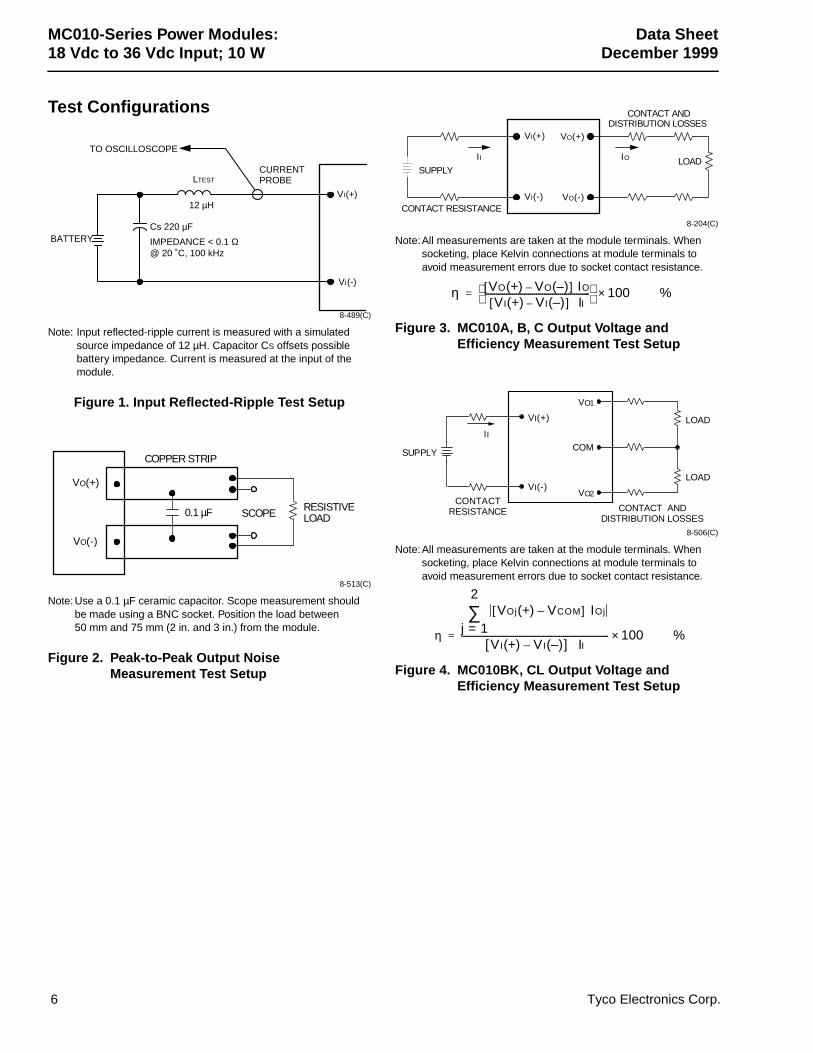
Test Configurations
8-489(C)
Note: Input reflected-ripple current is measured with a simulated source impedance of 12 µH. Capacitor CS offsets possible battery impedance. Current is measured at the input of the module.
Figure 1. Input Reflected-Ripple Test Setup
8-513(C)
Note: Use a 0.1 µF ceramic capacitor. Scope measurement should be made using a BNC socket. Position the load between 50 mm and 75 mm (2 in. and 3 in.) from the module.
Figure 2. Peak-to-Peak Output Noise Measurement Test Setup
8-204(C)
Note:All measurements are taken at the module terminals. When socketing, place Kelvin connections at module terminals to avoid measurement errors due to socket contact resistance.
Figure 3. MC010A, B, C Output Voltage and Efficiency Measurement Test Setup
8-506(C)
Note:All measurements are taken at the module terminals. When socketing, place Kelvin connections at module terminals to avoid measurement errors due to socket contact resistance.
Figure 4. MC010BK, CL Output Voltage and Efficiency Measurement Test Setup
TO OSCILLOSCOPE
12 µHVI(+)
VI(-)
BATTERY
CURRENTPROBELTEST
IMPEDANCE < 0.1 Ω@ 20 ˚C, 100 kHz
Cs 220 µF
VO(+)
VO(-)
RESISTIVELOADSCOPE0.1 µF
COPPER STRIP
VI(+)
VI(-)
VO(+)
VO(-)
II IO
SUPPLY
CONTACT RESISTANCE
CONTACT ANDDISTRIBUTION LOSSES
LOAD
η VO(+) VO(–)–[ ] IO
VI(+) VI(–)–[ ] II-----------------------------------------------------
100×= %
SUPPLY
VI(+)
VI(-)
VO1
VO2
II
CONTACTRESISTANCE CONTACT AND
DISTRIBUTION LOSSES
LOAD
COM
LOAD
η
VOj(+) VCOM–[ ] IOj
j 1=
2
∑
VI(+) VI(–)–[ ] II-------------------------------------------------------------------------- 100×= %
6 Tyco Electronics Corp.
Data Sheet MC010-Series Power Modules:December 1999 18 Vdc to 36 Vdc Input; 10 W
Design Considerations
Input Source Impedance
The power module should be connected to a low-ac-impedance input source. Source impedances greater than 12 µH can affect the stability of the power module. When the source impedance exceeds 12 µH, mount a 33 µF electrolytic capacitor (ESR < 0.7 ¾ at 100 kHz) close to the module input pins. This is also recom-mended to minimize reflected-ripple current as well as conducted and radiated electromagnetic interference (EMI).
Output Voltage Reversal
CAUTION: Applying a reverse voltage across the module output forward biases an inter-nal diode. Attempting to start the mod-ule under this condition can damage the module.
Safety Considerations
For safety-agency approval of the system in which the power module is used, the power module must be installed in compliance with the spacing and separation requirements of the end-use safety agency standard, i.e., UL 1950, CSA C22.2 No. 950-95, and VDE 0805 (EN60950, IEC950).
For the converter output to be considered meeting the requirements of safety extra-low voltage (SELV), the input must meet SELV requirements.
The power module has extra-low voltage (ELV) outputs when all inputs are ELV.
The input to these units is to be provided with a maxi-mum 5 A normal-blow fuse in the ungrounded lead.
Feature Descriptions
Overcurrent Protection
To provide protection in a fault (output overload) condi-tion, the unit is equipped with internal current-limiting and can endure current limiting for an unlimited dura-tion. At the point of current-limit inception, the unit shifts from voltage control to current control. If the out-put voltage is pulled very low during a severe fault, the
current-limit circuit can exhibit either foldback or tailout characteristics (output current decrease or increase). The unit operates normally once the output current is brought back into its specified range.
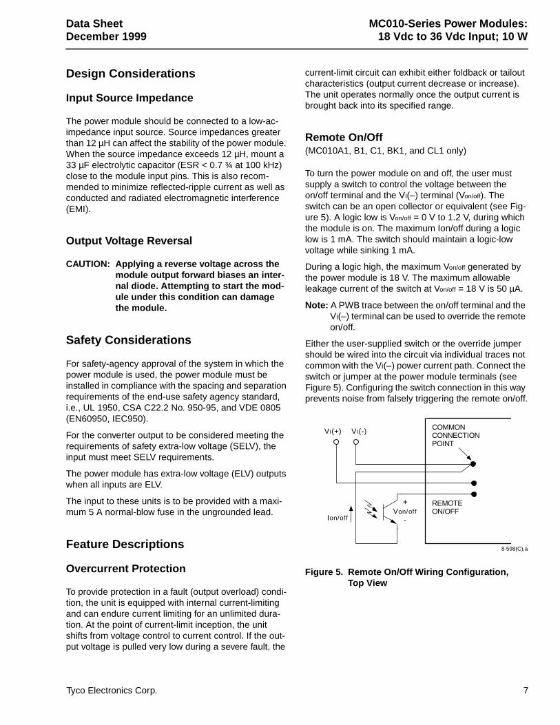
Remote On/Off(MC010A1, B1, C1, BK1, and CL1 only)
To turn the power module on and off, the user must supply a switch to control the voltage between the on/off terminal and the VI(–) terminal (Von/off). The switch can be an open collector or equivalent (see Fig-ure 5). A logic low is Von/off = 0 V to 1.2 V, during which the module is on. The maximum Ion/off during a logic low is 1 mA. The switch should maintain a logic-low voltage while sinking 1 mA.
During a logic high, the maximum Von/off generated by the power module is 18 V. The maximum allowable leakage current of the switch at Von/off = 18 V is 50 µA.
Note: A PWB trace between the on/off terminal and the VI(–) terminal can be used to override the remote on/off.
Either the user-supplied switch or the override jumper should be wired into the circuit via individual traces not common with the VI(–) power current path. Connect the switch or jumper at the power module terminals (see Figure 5). Configuring the switch connection in this way prevents noise from falsely triggering the remote on/off.
8-598(C).a
Figure 5. Remote On/Off Wiring Configuration, Top View
VI(+) VI(-) COMMONCONNECTIONPOINT
Von/off+
-Ion/off
REMOTEON/OFF
Tyco Electronics Corp. 7
MC010-Series Power Modules: Data Sheet18 Vdc to 36 Vdc Input; 10 W December 1999
Feature Descriptions (continued)
Output Overvoltage Protection
The output overvoltage clamp consists of control cir-cuitry, independent of the primary regulation loop, that monitors the voltage on the output terminals. The con-trol loop of the clamp has a higher voltage set point than the primary loop (see Feature Specifications table). This provides a redundant voltage-control that reduces the risk of output overvoltage.
Thermal Considerations
Although the power module is designed for an 85þ°C maximum operating ambient temperature, the charac-terization of the local thermal environment becomes more critical as temperatures exceed 70þ°C. The maxi-mum operating ambient temperature for the module is based on the maximum safe operating temperature of the devices contained inside it. Variations in local tem-perature and airflow, as well as the methods and loca-tion of measurement for these parameters, can affect the resulting internal temperature rises for a given ambient temperature. For ambient temperatures exceeding 70þ°C, call technical support for application assistance.
8 Tyco Electronics Corp.
Data SheetDecember 1999 18 Vdc to 36 Vdc Input; 10 W
MC010-Series Power Modules:
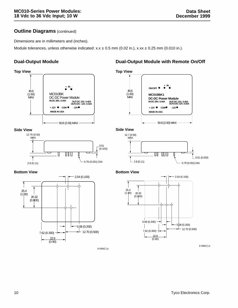
Outline Diagrams
Dimensions are in millimeters and (inches).
Module tolerances, unless otherwise indicated: x.x ± 0.5 mm (0.02 in.), x.xx ± 0.25 mm (0.010 in.).
Tyco Electronics Corp. 9
Single-Output Module
Top View
Side View
Bottom View
8-515(C).b
Single-Output Module with Remote On/Off
Top View
Side View
Bottom View
8-522(C).b
50.8 (2.00) MAX
+ IN -
MC010ADC-DC Power Module28V 0.45A IN 5V 2A OUT
+ OUT -
40.6(1.60)MAX
MADE IN USA
0.79 (0.031) DIA
12.7 (0.50)MAX
2.8 (0.11)
0.51 (0.020)
22.9(0.90)
12.70 (0.500)
5.08 (0.200)
25.4(1.00)
20.32(0.800)
7.62 (0.300)
50.8 (2.00) MAX
MADE IN USA
+ IN -
+ OUT -
MC010A1DC-DC Power Module 28V 0.45A IN 5V 2A OUT
ON/OFF40.6(1.60)MAX
0.79 (0.031) DIA2.8 (0.11)
12.7 (0.50)MAX
0.51 (0.020)
12.70 (0.500)
5.08 (0.200)
22.9(0.90)
20.32(0.800)
25.4(1.00)
7.62 (0.300)
5.08 (0.200)
Data SheetDecember 199918 Vdc to 36 Vdc Input; 10 W
MC010-Series Power Modules:
Outline Diagrams (continued)
Dimensions are in millimeters and (inches).
Module tolerances, unless otherwise indicated: x.x ± 0.5 mm (0.02 in.), x.xx ± 0.25 mm (0.010 in.).
10 Tyco Electronics Corp.
Dual-Output Module
Top View
Side View
Bottom View
8-589(C).b
Dual-Output Module with Remote On/Off
Top View
Side View
Bottom View
8-588(C).b
50.8 (2.00) MAX
+ IN -
+ 12V COM - 12V
MC010BKDC-DC Power ModuleIN:DC 28V, 0.44A OUT:DC 12V, 0.42A
OUT2:DC -12V, 0.42A
40.6(1.60)MAX
MADE IN USA
12.70 (0.50)MAX
0.51(0.020)
0.79 (0.031) DIA2.8 (0.11)
2.54 (0.100)
22.9(0.90)
12.70 (0.500)
25.4(1.00)
20.32(0.800)
5.08 (0.200)
7.62 (0.300)
50.8 (2.00) MAX
+ IN -
+ 12V COM - 12V
MC010BK1DC-DC Power ModuleIN:DC 28V, 0.44A OUT:DC 12V, 0.42A
OUT2:DC-12V, 0.42A
ON/OFF
MADE IN USA
40.6(1.60)MAX
0.51 (0.020)
12.7 (0.50)MAX
0.79 (0.031) DIA2.8 (0.11)
2.54 (0.100)
12.70 (0.500)
5.08 (0.200)
20.32(0.800)
25.4(1.00)
7.62 (0.300)
5.08 (0.200)
22.9(0.90)
Data SheetDecember 1999 18 Vdc to 36 Vdc Input; 10 W
MC010-Series Power Modules:
Tyco Electronics Corp. 11
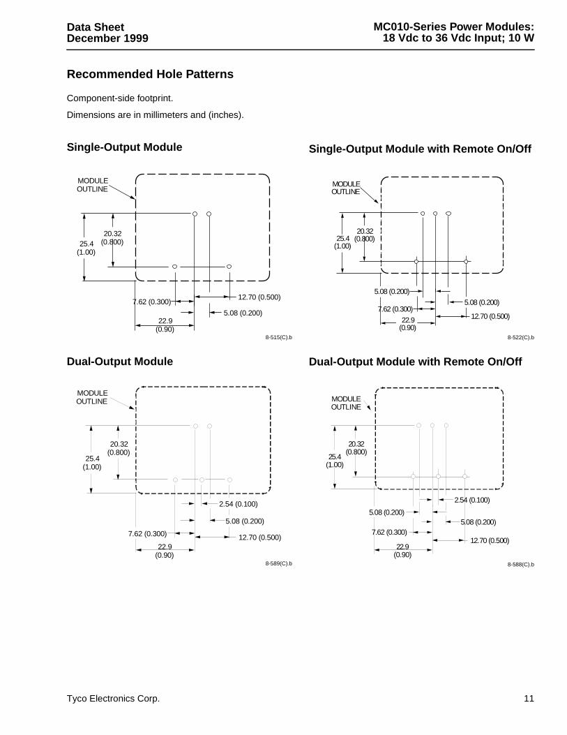
Recommended Hole Patterns
Component-side footprint.
Dimensions are in millimeters and (inches).
Single-Output Module
8-515(C).b
Dual-Output Module
8-589(C).b
Single-Output Module with Remote On/Off
8-522(C).b
Dual-Output Module with Remote On/Off
8-588(C).b
12.70 (0.500)
5.08 (0.200)
7.62 (0.300)
22.9(0.90)
MODULEOUTLINE
20.32(0.800)25.4
(1.00)
12.70 (0.500)22.9
(0.90)
MODULEOUTLINE
2.54 (0.100)
5.08 (0.200)
7.62 (0.300)
20.32(0.800)
25.4(1.00)
22.9(0.90)
12.70 (0.500)7.62 (0.300)
MODULEOUTLINE
20.32(0.800)25.4
(1.00)
5.08 (0.200)
5.08 (0.200)
22.9(0.90)
12.70 (0.500)7.62 (0.300)
5.08 (0.200)
2.54 (0.100)
MODULEOUTLINE
25.4(1.00)
20.32(0.800)
5.08 (0.200)

Data SheetDecember 199918 Vdc to 36 Vdc Input; 10 W
MC010-Series Power Modules:
Ordering Information
For assistance in ordering, please contact your Tyco Electronics’ Account Manager or Application Engineer.
InputVoltage
OutputVoltage
Output PowerRemote On/Off
LogicDeviceCode
Comcode
18 V—36 V 5 V 10 W No MC010A 10646415918 V—36 V 5 V 10 W Yes MC010A1 10646420918 V—36 V 12 V 10 W No MC010B 10646416718 V—36 V 12 V 10 W Yes MC010B1 10646421718 V—36 V 15 V 10 W No MC010C 10646417518 V—36 V 15 V 10 W Yes MC010C1 10646428218 V—36 V +12 V, –12 V 10 W No MC010BK 10646431618 V—36 V +12 V, –12 V 10 W Yes MC010BK1 10646439918 V—36 V +15 V, –15 V 10 W No MC010CL 10646436518 V—36 V +15 V, –15 V 10 W Yes MC010CL1 106464407
Printed onRecycled Paper
World Wide HeadquartersTyco Electronics Power Systems, Inc.3000 Skyline Drive, Mesquite, TX 75149, USA+1-800-526-7819 FAX: +1-888-315-5182 (Outside U.S.A.: +1-972-284-2626, FAX: +1-972-284-2900)www.power.tycoelectronics.come-mail: [email protected]
Tyco Electronics Corporation reserves the right to make changes to the product(s) or information contained herein without notice. No liability is assumed as a result of their use or application. No rights under any patent accompany the sale of any such product(s) or information.
© 2001 Tyco Electronics Power Systems, Inc. (Mesquite, Texas) All International Rights Reserved.Printed in U.S.A.
December 1999DS98-304EPS (Replaces DS91-197EPS)
Europe, Middle-East and Africa HeadquartersTyco Electronics (UK) LtdTel: +44 (0) 1344 469 300, Fax: +44 (0) 1344 469 301
Central America-Latin America HeadquartersTyco Electronics Power SystemsTel: +54 11 4316 2866, Fax: +54 11 4312 9508
Asia-Pacific HeadquartersTyco Electronics Singapore Pte LtdTel: +65 482 0311, Fax: 65 480 9299


