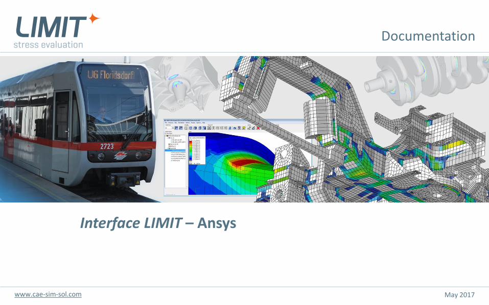
Download - Interface LIMIT – Ansys - cae-sim-sol.at
May 2017
Interface LIMIT – Ansys
www.cae-sim-sol.com
Documentation
Seite 2Interface LIMIT – Ansyswww.cae-sim-sol.com
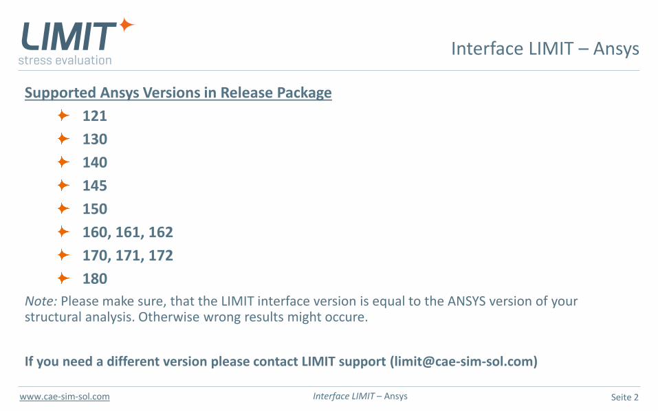
Supported Ansys Versions in Release Package
121
130
140
145
150
160, 161, 162
170, 171, 172
180
Note: Please make sure, that the LIMIT interface version is equal to the ANSYS version of yourstructural analysis. Otherwise wrong results might occure.
If you need a different version please contact LIMIT support ([email protected])
Interface LIMIT – Ansys
Seite 3Interface LIMIT – Ansyswww.cae-sim-sol.com
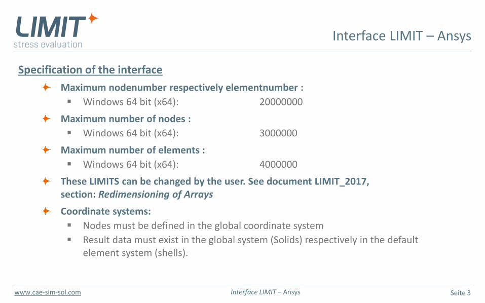
Specification of the interface
Maximum nodenumber respectively elementnumber :
▪ Windows 64 bit (x64): 20000000
Maximum number of nodes :
▪ Windows 64 bit (x64): 3000000
Maximum number of elements :
▪ Windows 64 bit (x64): 4000000
These LIMITS can be changed by the user. See document LIMIT_2017, section: Redimensioning of Arrays
Coordinate systems:
▪ Nodes must be defined in the global coordinate system
▪ Result data must exist in the global system (Solids) respectively in the defaultelement system (shells).
Interface LIMIT – Ansys
Seite 4Interface LIMIT – Ansyswww.cae-sim-sol.com
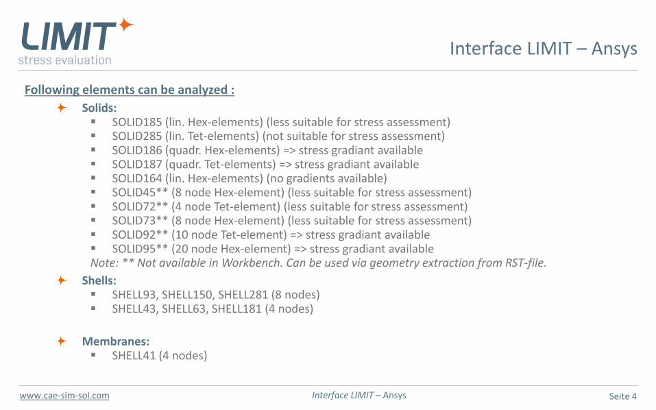
Following elements can be analyzed :
Solids: ▪ SOLID185 (lin. Hex-elements) (less suitable for stress assessment)▪ SOLID285 (lin. Tet-elements) (not suitable for stress assessment)▪ SOLID186 (quadr. Hex-elements) => stress gradiant available▪ SOLID187 (quadr. Tet-elements) => stress gradiant available▪ SOLID164 (lin. Hex-elements) (no gradients available)▪ SOLID45** (8 node Hex-element) (less suitable for stress assessment)▪ SOLID72** (4 node Tet-element) (less suitable for stress assessment)▪ SOLID73** (8 node Hex-element) (less suitable for stress assessment)▪ SOLID92** (10 node Tet-element) => stress gradiant available▪ SOLID95** (20 node Hex-element) => stress gradiant availableNote: ** Not available in Workbench. Can be used via geometry extraction from RST-file.
Shells: ▪ SHELL93, SHELL150, SHELL281 (8 nodes)▪ SHELL43, SHELL63, SHELL181 (4 nodes)
Membranes:▪ SHELL41 (4 nodes)
Interface LIMIT – Ansys
Seite 5Interface LIMIT – Ansyswww.cae-sim-sol.com
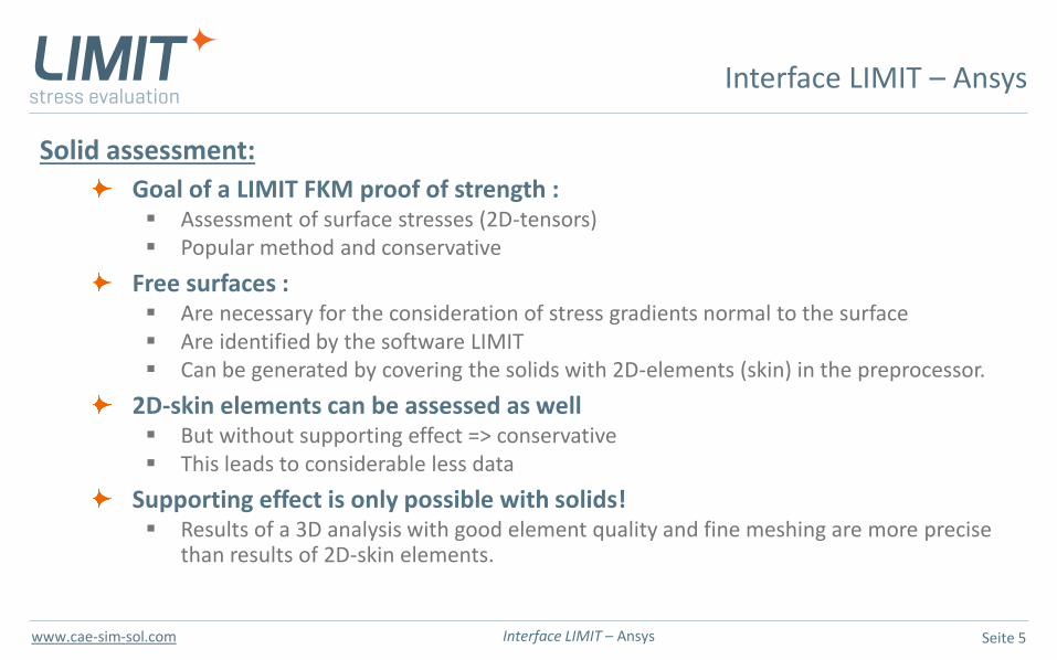
Solid assessment:
Goal of a LIMIT FKM proof of strength : ▪ Assessment of surface stresses (2D-tensors)▪ Popular method and conservative
Free surfaces : ▪ Are necessary for the consideration of stress gradients normal to the surface▪ Are identified by the software LIMIT▪ Can be generated by covering the solids with 2D-elements (skin) in the preprocessor.
2D-skin elements can be assessed as well▪ But without supporting effect => conservative▪ This leads to considerable less data
Supporting effect is only possible with solids! ▪ Results of a 3D analysis with good element quality and fine meshing are more precise
than results of 2D-skin elements.
Interface LIMIT – Ansys
Seite 6Interface LIMIT – Ansyswww.cae-sim-sol.com
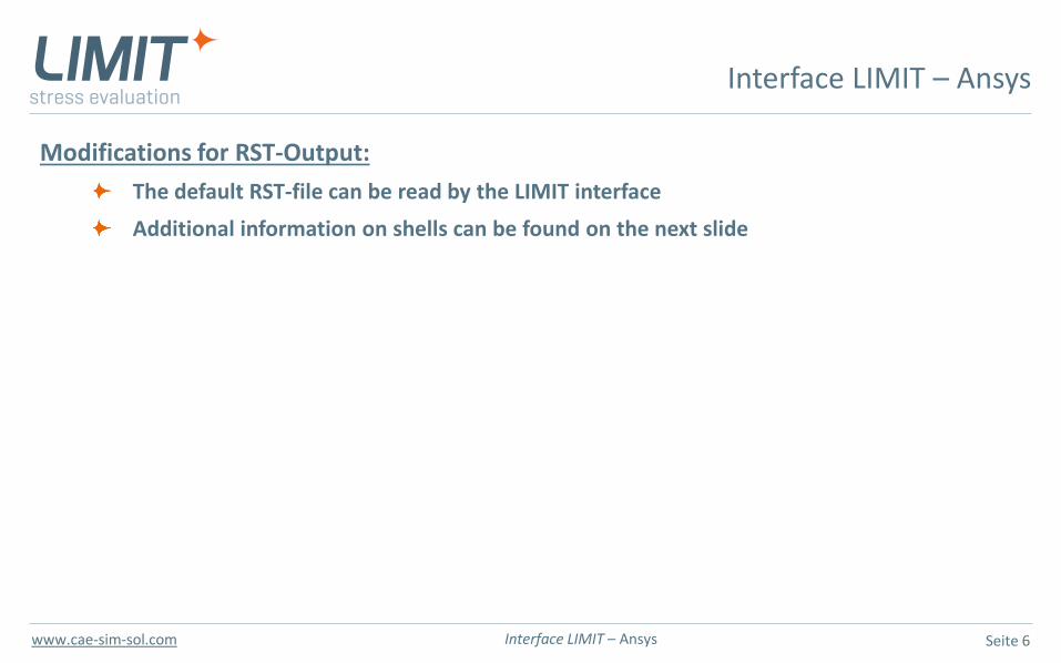
Modifications for RST-Output:
The default RST-file can be read by the LIMIT interface
Additional information on shells can be found on the next slide
Interface LIMIT – Ansys
Seite 7Interface LIMIT – Ansyswww.cae-sim-sol.com
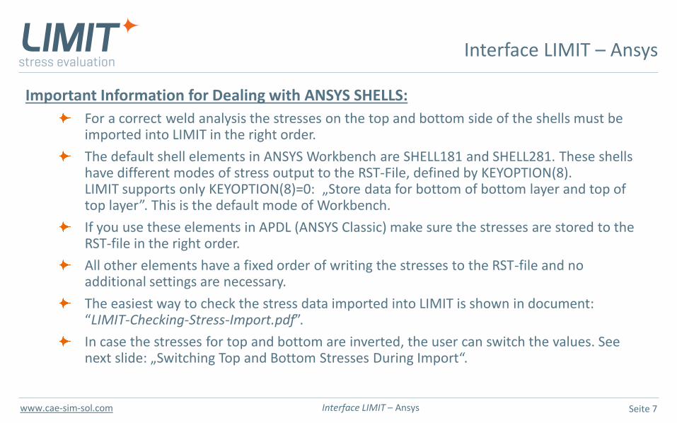
Important Information for Dealing with ANSYS SHELLS:
For a correct weld analysis the stresses on the top and bottom side of the shells must beimported into LIMIT in the right order.
The default shell elements in ANSYS Workbench are SHELL181 and SHELL281. These shellshave different modes of stress output to the RST-File, defined by KEYOPTION(8).LIMIT supports only KEYOPTION(8)=0: „Store data for bottom of bottom layer and top of top layer”. This is the default mode of Workbench.
If you use these elements in APDL (ANSYS Classic) make sure the stresses are stored to the RST-file in the right order.
All other elements have a fixed order of writing the stresses to the RST-file and no additional settings are necessary.
The easiest way to check the stress data imported into LIMIT is shown in document: “LIMIT-Checking-Stress-Import.pdf”.
In case the stresses for top and bottom are inverted, the user can switch the values. See next slide: „Switching Top and Bottom Stresses During Import“.
Interface LIMIT – Ansys
Seite 8Interface LIMIT – Ansyswww.cae-sim-sol.com
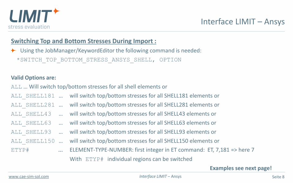
Switching Top and Bottom Stresses During Import :
Using the JobManager/KeywordEditor the following command is needed:
*SWITCH_TOP_BOTTOM_STRESS_ANSYS_SHELL, OPTION
Valid Options are:
ALL … Will switch top/bottom stresses for all shell elements or
ALL_SHELL181 … will switch top/bottom stresses for all SHELL181 elements or
ALL_SHELL281 … will switch top/bottom stresses for all SHELL281 elements or
ALL_SHELL43 … will switch top/bottom stresses for all SHELL43 elements or
ALL_SHELL63 … will switch top/bottom stresses for all SHELL63 elements or
ALL_SHELL93 … will switch top/bottom stresses for all SHELL93 elements or
ALL_SHELL150 … will switch top/bottom stresses for all SHELL150 elements or
ETYP# … ELEMENT-TYPE-NUMBER: first integer in ET command: ET, 7,181 => here 7
With ETYP# individual regions can be switched
Examples see next page!
Interface LIMIT – Ansys
Seite 9Interface LIMIT – Ansyswww.cae-sim-sol.com
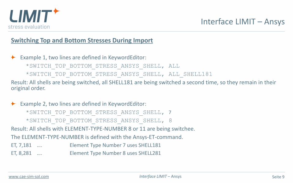
Switching Top and Bottom Stresses During Import
Example 1, two lines are defined in KeywordEditor:
*SWITCH_TOP_BOTTOM_STRESS_ANSYS_SHELL, ALL
*SWITCH_TOP_BOTTOM_STRESS_ANSYS_SHELL, ALL_SHELL181
Result: All shells are being switched, all SHELL181 are being switched a second time, so they remain in their original order.
Example 2, two lines are defined in KeywordEditor:
*SWITCH_TOP_BOTTOM_STRESS_ANSYS_SHELL, 7
*SWITCH_TOP_BOTTOM_STRESS_ANSYS_SHELL, 8
Result: All shells with ELEMENT-TYPE-NUMBER 8 or 11 are being switchee.
The ELEMENT-TYPE-NUMBER is defined with the Ansys-ET-command.
ET, 7,181 …. Element Type Number 7 uses SHELL181
ET, 8,281 …. Element Type Number 8 uses SHELL281
Interface LIMIT – Ansys
Seite 10Interface LIMIT – Ansyswww.cae-sim-sol.com
Last slide
Interface LIMIT – Ansys


