International Journal of Engineering and Technology Volume 4 No. 10, October, 2014
ISSN: 2049-3444 © 2014 – IJET Publications UK. All rights reserved. 595
GSM Based Intelligent Home Security System for Intrusion Detection
Omorogiuwa Eseosa1, Elechi Promise2
1Department of Electrical/Electronic Engineering
University of Port Harcourt, Port Harcourt, Nigeria 2Department of Electrical Engineering,
Rivers State University of Science and Technology, Port Harcourt, Nigeria
ABSTRACT
Conventional security systems which are the commonest form of protection to lives and properties, have certain limitations such as real
time monitoring and control of activities such as intruders in the form of human beings, fire, smoke, etc. These limitations in most cases
result in high financial loss to properties and lives. This work involves design and construction of GSM intelligent home security system
for real time monitoring of intruders. It consist of intrusion detection sensors, (pressure, Smoke/Fire, Gas and PIR motion), wireless sensors,
programmable microcontroller in embedded C language, regulated power supply unit, proteus (circuit simulator), relays, GSM modem,
mobile phone, data acquisition node and an interface program development. The design calculation and analysis was carried out before it
was modeled, simulated in proteus electronic simulator environment. When the PIR finds intruders ( in form of variation in temperature,
gas leakage, pressure, etc), the relevant sensing device(s) respond and the microcontroller sends encoded alarm signal to the wireless sensor
network established in home. The moment the alarm signal is received, it will send alarm short message to the users (owners of the building)
through GSM network immediately. The design analysis and calculations were carried out and finally, a positive result was achieved.
Keywords: Intruder, Detector, GSM, Intelligent and Security
1. INTRODUCTION
In today’s age of digital technology and intelligent systems,
home automation has become one of the fastest developing
application based technologies in the world. The idea of
comfortable living in homes has since changed for the past
decade as digital and wireless technologies, are integrated into it.
The main concept behind the work is receiving sent Short
Message Services (SMS) and processing it further as required to
perform several operations. There are several terminologies that
are used extensively throughout this paper such as Global System
for Mobile Communication (GSM), SMS, etc. It is a service
available on most digital mobile phones (also known as text
messaging service). Intelligent homes in simple terms can be
described as homes that are fully automated in terms of carrying
out a predetermined task, providing feed back to the home users
and responding accordingly to situations. Intelligent home
security systems such as controlled network, and communication
systems, emergency response, anti-theft monitoring systems
requires automated and controlled system both near and at a
distance of control. Intelligent home security systems play
important roles in providing an extra layer of security through
user authentication to prevent break-ins at entry points and also
to track illegal intrusions or activities within the vicinity of the
home. There are many researches done in the design of various
types of intelligent home security system like sensor-based
system that reply and contact-based systems such as finger-print
and palm-print scan that requires substantial amount with an
input device. Many intelligent home security systems are based
on a single system. GSM technology provides the benefit that
intelligent home security system is accessible in remote areas as
well.
This paper is aimed at designing a GSM based intelligent home
security system for detecting an intrusion into a monitored area
by a passive infrared detector. For home safety, intrusion detector
has a transmitter coupled with portable receiver to alert home
owners through SMS in situations of break-ins or entering into
the home using force.
Home security system has been a feature of science fiction
writing for many years, but has become practical since the early
20th century following the widespread introduction of electricity
into the home, and rapid advancement of information
technology. Early remote control devices began to emerge in the
late 1800s for example, Nikola Tesla, patented an idea for remote
control of vessels and vehicles (Tesla, 1898) in a research work
titled “Method for Controlling Mechanisms of Moving Vessels
and Vehicles”. The emergence of electrical home appliances
began between 1915 and 1920. More so, the decline in domestic
servants meant for the household needed cheap, mechanical
replacement. Domestic electricity supply however was still in its
infant stage-meaning this luxury was afforded only by the more
affluent households as investigated and published by Harper in
2003. Ideas similar to intelligent home security systems
originated during the world fairs of the 1930s (Mann, 2005) as
reported in the work titled “Smart Technology for Aging,
Disability and Independence Depicted Electrified and
Automated Homes”. In 1966, Jim Sutherland an engineer
working for Westinghouse Electric developed home security
system called “ECHO IV”. This was however, a private project
International Journal of Engineering and Technology (IJET) – Volume 4 No. 10, October, 2014
ISSN: 2049-3444 © 2014 – IJET Publications UK. All rights reserved. 596
and never commercialized. The first “wired home” were built by
American hobbyist during the 1960’s using the available
technology of the times. The term “Smart Home” was first coined
by the American Association of House builders in 1984 with the
invention of microcontrollers. The cost of electronic control fell
rapidly as time progresses thus making it more affordable.
Remote and intelligent control technologies were adopted by the
building services industry and appliance manufacturers
worldwide, as they offer end users easy accessibility and/or
greater control in their products (Harper, 2003). During the
1990’s, home security systems rose to prominence by the end of
the decade, domotics was commonly used to describe any system
in which informatics and telematics were combined to support
activities in the home. The phrase appears to be a portmanteau
word formed from domus (Latin meaning house) and informatics
referring specifically to the application of computer technology
to domestic appliances (Gerhart, 1999). As described by the
author in the work titled “Home Automation and Wiring”.
Despite interest in home security systems, by the end of 1990’s,
there was still no widespread uptake with such systems as it was
still considered as the domain of hobbyist or the rich. The major
challenge was however traced to lack of a single, simplified,
protocol and high cost of the device, thus resulting in not making
customers to be able to afford it.
While there is still much room for growth, according to
researchers, one million, five hundred thousand home security
systems were installed in the US in 2012 and sharp uptake could
see shipments topping over eight million in 2017 (ABI Research,
2012).
Intelligent home security system involves automation of homes
or household activities such as security locks of gates and doors.
The overall idea is to provide improved efficiency and security
in their place /areas of applications. In recent years, the
popularity of home automation has been increasingly great
because of its affordability and simplified design through
smartphones, internet connectivity/facilities and cable
connectivity. Devices may be connected through a computer
network to allow control by a personal computer, and may allow
remote access from the internet. Through the integration of
information technologies with the home security, systems are
able to communicate in an integrated manner which results in
convenience, energy efficiency and safety benefit.
GSM based intelligent home security system refers to the use of
device and information technology to control home
features/systems (such as windows, doors, etc.). Parameters to be
controlled in any system could be very simple/complex. These
can range from single control of lighting through complex
computer/microcontroller based networks with varying degrees
of automation. Home security system is adopted for reasons of
ease, security and energy efficiency. The controller devices are
properly interconnected such that there is obvious
communication between the home appliance/device and the
controller. For example, an alert message is sent through
telephone line in case of any intrusion taking place. The
automated device then makes the home intelligent and will call
neighbour(s), or any other emergency line dedicated to
intrusion(s) cases/attempt. It does the monitoring via GSM
handset or web browser. One of the areas of application of
intelligent home automation system is in smoke detection. An
example of remote monitoring in intelligent home security
system could be triggered when a smoke detector detect a fire or
smoke condition. The system could also call the home owner on
their mobile phone to alert them, or alert the neighbour(s).
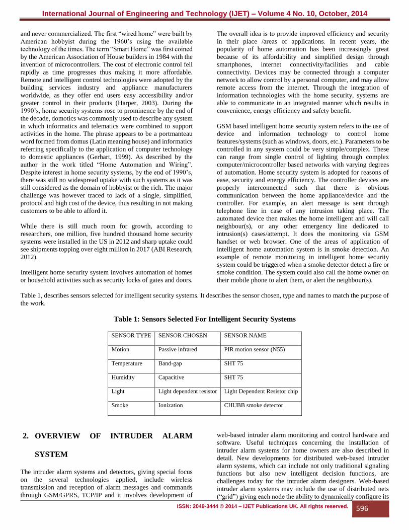
Table 1, describes sensors selected for intelligent security systems. It describes the sensor chosen, type and names to match the purpose of
the work.
Table 1: Sensors Selected For Intelligent Security Systems
SENSOR TYPE SENSOR CHOSEN SENSOR NAME
Motion Passive infrared PIR motion sensor (N55)
Temperature Band-gap SHT 75
Humidity Capacitive SHT 75
Light Light dependent resistor Light Dependent Resistor chip
Smoke Ionization CHUBB smoke detector
2. OVERVIEW OF INTRUDER ALARM
SYSTEM
The intruder alarm systems and detectors, giving special focus
on the several technologies applied, include wireless
transmission and reception of alarm messages and commands
through GSM/GPRS, TCP/IP and it involves development of
web-based intruder alarm monitoring and control hardware and
software. Useful techniques concerning the installation of
intruder alarm systems for home owners are also described in
detail. New developments for distributed web-based intruder
alarm systems, which can include not only traditional signaling
functions but also new intelligent decision functions, are
challenges today for the intruder alarm designers. Web-based
intruder alarm systems may include the use of distributed nets
(“grid”) giving each node the ability to dynamically configure its
International Journal of Engineering and Technology (IJET) – Volume 4 No. 10, October, 2014
ISSN: 2049-3444 © 2014 – IJET Publications UK. All rights reserved. 597
functions within entire respect for the security scope issues
(Antunes, 2007). The distributed network intelligence will allow
an intruder alarm system to react to multi-signalization intrusion
situations in much more efficient ways, being also able to
distinguish more accurately real security violation adverted
operations.
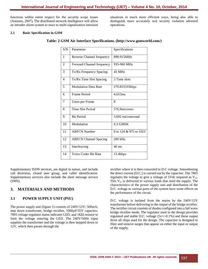
2.1 Basic Specification in GSM
Table: 2 GSM Air Interface Specifications. (http://www.gsmworld.com/)
S/N Parameter Specifications
1 Reverse Channel frequency 890-915MHz
2 Forward Channel frequency 935-960 MHz
3 Tx/Rx Frequency Spacing 45 MHz
4 Tx/Rx Time Slot Spacing 3 Time slots
5 Modulation Data Rate 270.833333kbps
6 Frame Period 4.615ms
7 Users per Frame 8
8 Time Slot Period 576.9microsec
9 Bit Period 3.692 microsecond
10 Modulation 0.3 GMSK
11 ARFCN Number 0 to 124 & 975 to 1023
12 ARFCN Channel Spacing 200 kHz
13 Interleaving 40 ms
14 Voice Coder Bit Rate 13.4kbps
Supplementary ISDN services, are digital in nature, and include
call diversion, closed user group, and caller identification.
Supplementary services also include the short message service
(SMS).
3. MATERIALS AND METHODS
3.1 POWER SUPPLY UNIT (PSU)
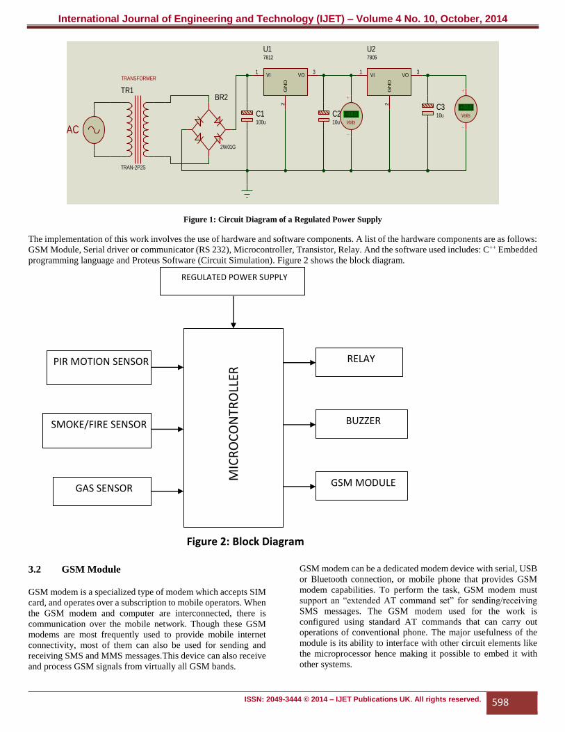
The power supply unit (figure 1) consists of 240V/12V; 500mA;
step down transformer, bridge rectifier, 1000µF/35V capacitor,
7805 voltage regulator status indicator LED, and 1KΏ resistor to
limit the voltage entering the LED. The 240V/50Hz input
supplies the transformer and the voltage is then stepped down to
12V, which then passes through the
rectifier where it is then converted to D.C voltage. Smoothening
the direct current (D.C.) is carried out by the capacitor .The 7805
regulates the voltage to give a voltage of 5Vdc required as Vcc.
This Vсс is delivered to various loads that need the supply. The
characteristics of the power supply unit and distribution of the
D.C. voltage to various parts of the system have some effects on
the performance of the circuit.
D.C. voltage is isolated from the mains by the 240V/12V
transformer before delivering to the output of the bridge rectifier.
The rectifier circuit consists of diodes configured into a full wave
bridge rectifier mode. The regulator used in the design provides
regulated and stable D.C. voltage (5v+/-0.1%) and these output
drive all chips used for the design .The capacitor is designed to
filter and remove surges that appear on either the input or output
of the supply.
International Journal of Engineering and Technology (IJET) – Volume 4 No. 10, October, 2014
ISSN: 2049-3444 © 2014 – IJET Publications UK. All rights reserved. 598
Figure 1: Circuit Diagram of a Regulated Power Supply
The implementation of this work involves the use of hardware and software components. A list of the hardware components are as follows:
GSM Module, Serial driver or communicator (RS 232), Microcontroller, Transistor, Relay. And the software used includes: C++ Embedded
programming language and Proteus Software (Circuit Simulation). Figure 2 shows the block diagram.
3.2 GSM Module
GSM modem is a specialized type of modem which accepts SIM
card, and operates over a subscription to mobile operators. When
the GSM modem and computer are interconnected, there is
communication over the mobile network. Though these GSM
modems are most frequently used to provide mobile internet
connectivity, most of them can also be used for sending and
receiving SMS and MMS messages.This device can also receive
and process GSM signals from virtually all GSM bands.
GSM modem can be a dedicated modem device with serial, USB
or Bluetooth connection, or mobile phone that provides GSM
modem capabilities. To perform the task, GSM modem must
support an “extended AT command set” for sending/receiving
SMS messages. The GSM modem used for the work is
configured using standard AT commands that can carry out
operations of conventional phone. The major usefulness of the
module is its ability to interface with other circuit elements like
the microprocessor hence making it possible to embed it with
other systems.
BR2
2W01G
C1100u
TR1
TRAN-2P2S
VI1
VO3
GN
D2
U17812
C210u
C310u
AC
TRANSFORMER
+88.8
Volts
VI1
VO3
GN
D2
U27805
+88.8
Volts
REGULATED POWER SUPPLY
MIC
RO
CO
NTR
OLL
ER RELAY
BUZZER
GSM MODULE
PIR MOTION SENSOR
SMOKE/FIRE SENSOR
GAS SENSOR
Figure 2: Block Diagram
International Journal of Engineering and Technology (IJET) – Volume 4 No. 10, October, 2014
ISSN: 2049-3444 © 2014 – IJET Publications UK. All rights reserved. 599
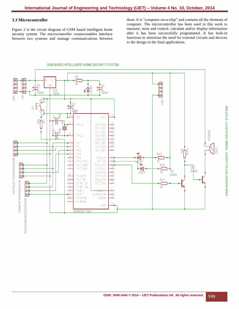
3.3 Microcontroller
Figure 2 is the circuit diagram of GSM based intelligent home
security system. The microcontroller creates/enables interface
between two systems and manage communications between
them. It is “computer-on-a-chip” and contains all the elements of
computer. The microcontroller has been used in this work to
measure, store and control, calculate and/or display information
after it has been successfully programmed. It has built-in
functions to minimize the need for external circuits and devices
to the design in the final applications.
International Journal of Engineering and Technology (IJET) – Volume 4 No. 10, October, 2014
ISSN: 2049-3444 © 2014 – IJET Publications UK. All rights reserved. 600
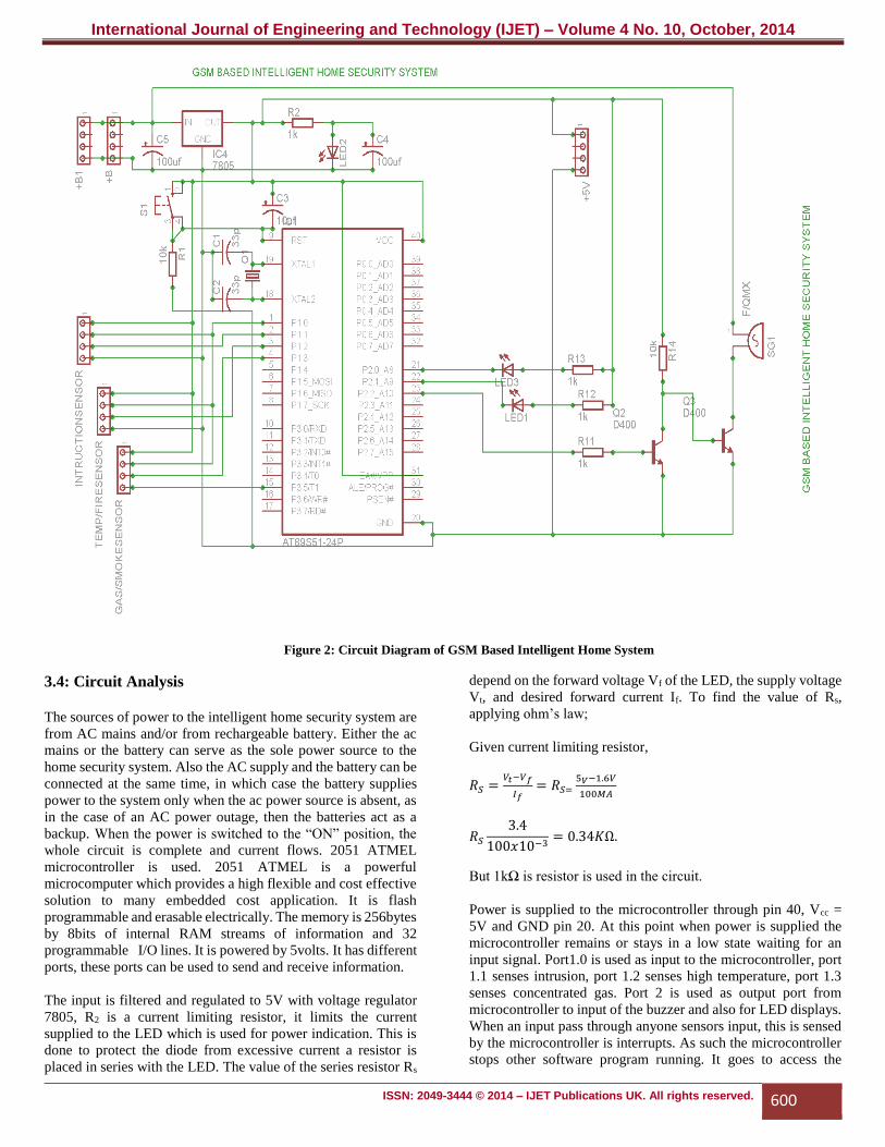
Figure 2: Circuit Diagram of GSM Based Intelligent Home System
3.4: Circuit Analysis
The sources of power to the intelligent home security system are
from AC mains and/or from rechargeable battery. Either the ac
mains or the battery can serve as the sole power source to the
home security system. Also the AC supply and the battery can be
connected at the same time, in which case the battery supplies
power to the system only when the ac power source is absent, as
in the case of an AC power outage, then the batteries act as a
backup. When the power is switched to the “ON” position, the
whole circuit is complete and current flows. 2051 ATMEL
microcontroller is used. 2051 ATMEL is a powerful
microcomputer which provides a high flexible and cost effective
solution to many embedded cost application. It is flash
programmable and erasable electrically. The memory is 256bytes
by 8bits of internal RAM streams of information and 32
programmable I/O lines. It is powered by 5volts. It has different
ports, these ports can be used to send and receive information.
The input is filtered and regulated to 5V with voltage regulator
7805, R2 is a current limiting resistor, it limits the current
supplied to the LED which is used for power indication. This is
done to protect the diode from excessive current a resistor is
placed in series with the LED. The value of the series resistor Rs
depend on the forward voltage Vf of the LED, the supply voltage
Vt, and desired forward current If. To find the value of Rs,
applying ohm’s law;
Given current limiting resistor,
𝑅𝑆 =𝑉𝑡−𝑉𝑓
𝐼𝑓 = 𝑅𝑆=
5𝑉−1.6𝑉
100𝑀𝐴
𝑅𝑆
3.4
100𝑥10−3= 0.34𝐾Ω.
But 1kΩ is resistor is used in the circuit.
Power is supplied to the microcontroller through pin 40, Vcc =
5V and GND pin 20. At this point when power is supplied the
microcontroller remains or stays in a low state waiting for an
input signal. Port1.0 is used as input to the microcontroller, port
1.1 senses intrusion, port 1.2 senses high temperature, port 1.3
senses concentrated gas. Port 2 is used as output port from
microcontroller to input of the buzzer and also for LED displays.
When an input pass through anyone sensors input, this is sensed
by the microcontroller is interrupts. As such the microcontroller
stops other software program running. It goes to access the
International Journal of Engineering and Technology (IJET) – Volume 4 No. 10, October, 2014
ISSN: 2049-3444 © 2014 – IJET Publications UK. All rights reserved. 601
address bus of the input signal and loads the program stored in
the address register, after loading, it sends to control register,
compute the signal based on the stored program and runs the
instruction. It sends out streams of instruction to the output
register or ports. The output instruction which set output high and
to send information to the GSM Modem, initializing to send SMS
to a program number and turn “ON” the indicator and buzzer.
The crystal oscillator determines the external frequency of the
microcontroller, the rate at which it processes information is
11.0592MHz. From power supply unit (PSU), the power is
supplied from the battery and filtered through capacitor C1, to
remove ripple or unwanted signal from the battery. The output
port 2.2 is low and can’t drive the buzzer .Therefore transistors
Q2, Q3 are used to amplify the output to drive the buzzer; R10 is
used to bias the input to base of the transistor Q2, to set the current
fed to the resistor. Q2 starts conducting when the transistor’s base
receives a control voltage/current, the transistor will turn “ON”
the buzzer. Switch S1 is the reset button; is used to reset the
microcontroller to its initialize state. The microcontroller in a
voltage- deprived state and will have the tendency to behave
erratically when the power supply voltage falls below the
required 5V. For this reason, a reset chip I is incorporated into
the design, forcing the PIC to reset to the beginning of the
program and hold until the supply voltage is within acceptable
limits.
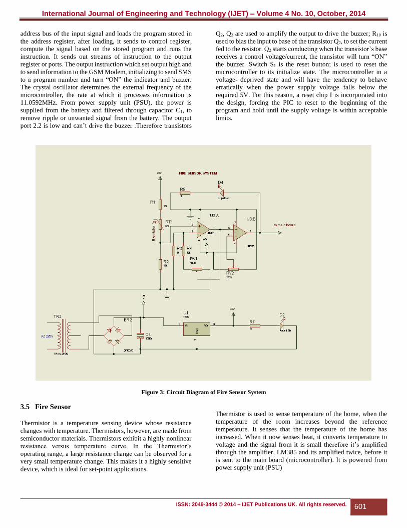
Figure 3: Circuit Diagram of Fire Sensor System
3.5 Fire Sensor
Thermistor is a temperature sensing device whose resistance
changes with temperature. Thermistors, however, are made from
semiconductor materials. Thermistors exhibit a highly nonlinear
resistance versus temperature curve. In the Thermistor’s
operating range, a large resistance change can be observed for a
very small temperature change. This makes it a highly sensitive
device, which is ideal for set-point applications.
Thermistor is used to sense temperature of the home, when the
temperature of the room increases beyond the reference
temperature. It senses that the temperature of the home has
increased. When it now senses heat, it converts temperature to
voltage and the signal from it is small therefore it’s amplified
through the amplifier, LM385 and its amplified twice, before it
is sent to the main board (microcontroller). It is powered from
power supply unit (PSU)
International Journal of Engineering and Technology (IJET) – Volume 4 No. 10, October, 2014
ISSN: 2049-3444 © 2014 – IJET Publications UK. All rights reserved. 602
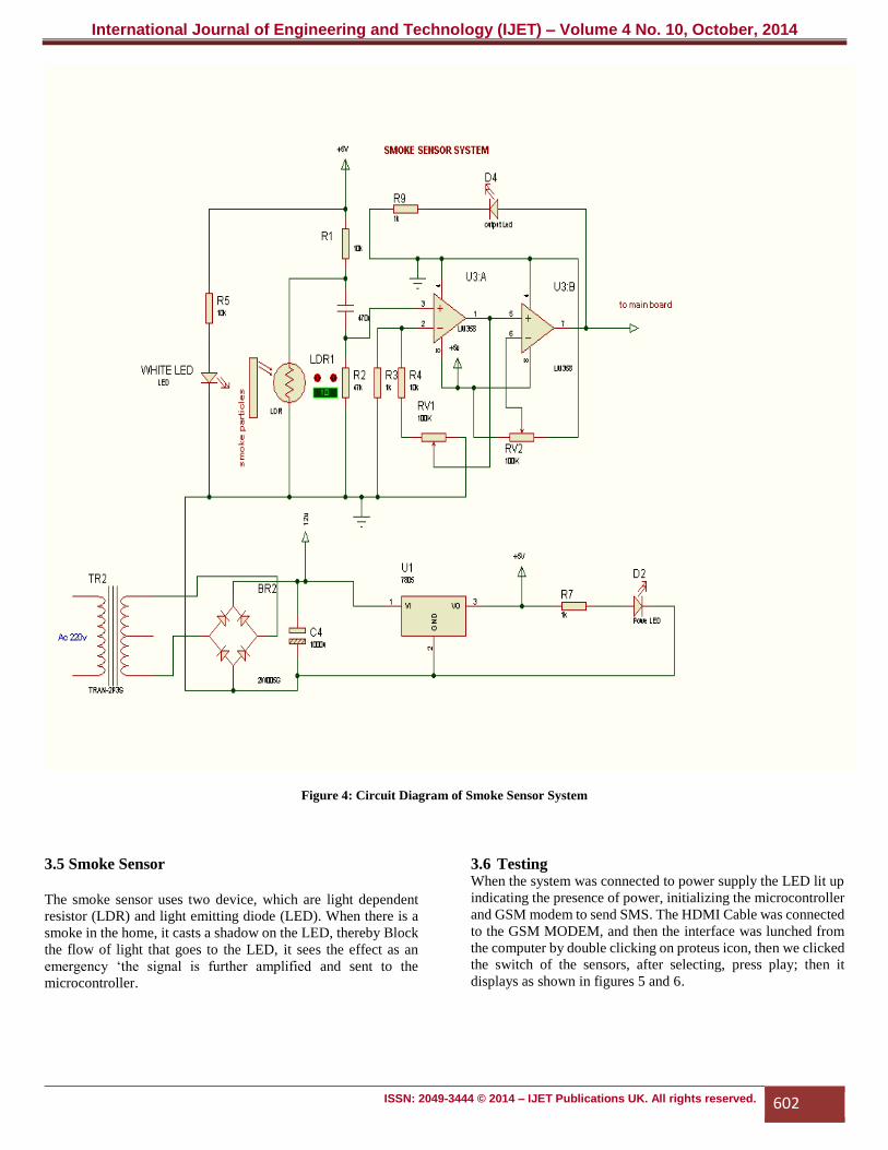
Figure 4: Circuit Diagram of Smoke Sensor System
3.5 Smoke Sensor
The smoke sensor uses two device, which are light dependent
resistor (LDR) and light emitting diode (LED). When there is a
smoke in the home, it casts a shadow on the LED, thereby Block
the flow of light that goes to the LED, it sees the effect as an
emergency ‘the signal is further amplified and sent to the
microcontroller.
3.6 Testing When the system was connected to power supply the LED lit up
indicating the presence of power, initializing the microcontroller
and GSM modem to send SMS. The HDMI Cable was connected
to the GSM MODEM, and then the interface was lunched from
the computer by double clicking on proteus icon, then we clicked
the switch of the sensors, after selecting, press play; then it
displays as shown in figures 5 and 6.
International Journal of Engineering and Technology (IJET) – Volume 4 No. 10, October, 2014
ISSN: 2049-3444 © 2014 – IJET Publications UK. All rights reserved. 603
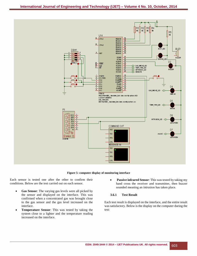
Figure 5: computer display of monitoring interface
Each sensor is tested one after the other to confirm their
conditions. Below are the test carried out on each sensor.
Gas Sensor: The varying gas levels were all picked by
the sensor and displayed on the interface. This was
confirmed when a concentrated gas was brought close
to the gas sensor and the gas level increased on the
interface.
Temperature Sensor: This was tested by taking the
system close to a lighter and the temperature reading
increased on the interface.
Passive infrared Sensor: This was tested by taking my
hand cross the receiver and transmitter, then buzzer
sounded meaning an intrusion has taken place.
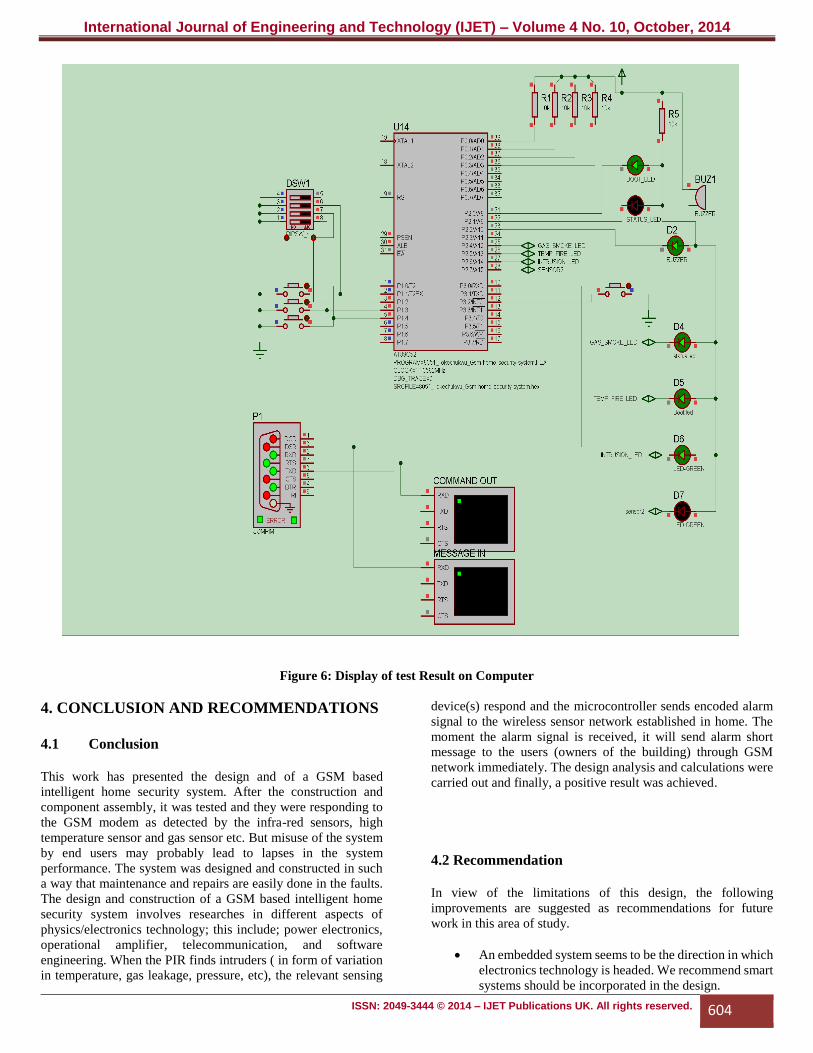
3.6.1 Test Result
Each test result is displayed on the interface, and the entire result
was satisfactory. Below is the display on the computer during the
test:
International Journal of Engineering and Technology (IJET) – Volume 4 No. 10, October, 2014
ISSN: 2049-3444 © 2014 – IJET Publications UK. All rights reserved. 604
Figure 6: Display of test Result on Computer
4. CONCLUSION AND RECOMMENDATIONS
4.1 Conclusion
This work has presented the design and of a GSM based
intelligent home security system. After the construction and
component assembly, it was tested and they were responding to
the GSM modem as detected by the infra-red sensors, high
temperature sensor and gas sensor etc. But misuse of the system
by end users may probably lead to lapses in the system
performance. The system was designed and constructed in such
a way that maintenance and repairs are easily done in the faults.
The design and construction of a GSM based intelligent home
security system involves researches in different aspects of
physics/electronics technology; this include; power electronics,
operational amplifier, telecommunication, and software
engineering. When the PIR finds intruders ( in form of variation
in temperature, gas leakage, pressure, etc), the relevant sensing
device(s) respond and the microcontroller sends encoded alarm
signal to the wireless sensor network established in home. The
moment the alarm signal is received, it will send alarm short
message to the users (owners of the building) through GSM
network immediately. The design analysis and calculations were
carried out and finally, a positive result was achieved.
4.2 Recommendation
In view of the limitations of this design, the following
improvements are suggested as recommendations for future
work in this area of study.
An embedded system seems to be the direction in which
electronics technology is headed. We recommend smart
systems should be incorporated in the design.
International Journal of Engineering and Technology (IJET) – Volume 4 No. 10, October, 2014
ISSN: 2049-3444 © 2014 – IJET Publications UK. All rights reserved. 605
Better microcontrollers are being produced all the time.
We recommend the use of the latest microcontrollers
and embedded microcontroller technology.
REFERENCES
[1] http://www.8051.projects.net
[2] http://www.gsmworld.com/about-us/history.html
[3] http//:en.wikipedia.org/wiki/gsm project
[4] AT Commands Set for Nokia GSM and WCDMA
products, Version 1.2, July 2005
[5] Gerhart, James (1999): Home Automation and Wiring,
McGraw-Hill Professional. ISBN 0070246742.
[6] Harper, Richard (2003): Inside the Smart Home,
Springer. ISBN 1852336889.
[7] Tesla, Nikola (1898): U.S. Patent 613809: Method of
and apparatus for controlling mechanism of moving
vessels and vehicles, United States Patent and
Trademark Office.
[8] Mann, W. C. (2005): Smart technology for aging,
disability and independence : the state of the science.
John Wiley and Sons. ISBN 0-471-69694-3.
[9] Antunes, R. (2007): Intruder alarm systems: The state
of the art, proceeding of the 2ND International
conference on electrical engineering (CEE”07): 251-
261. ISBN 972-99064-4-2
[10] Griffiths, M ( 2008): Smart Home Security:
Homebuilding & Renovating. ABI Research Mobile
(2012)//m.abireseach.com/
[11] Schertz P. (2000). Practical Electronics for Inventors.
Mc Graw Hills. 2nd edition.ISBN- 0-01-058078-2


