Download - A New Design for Cassino Hexapod Robot

1 Copyright © 2010 by ASME
Proceedings of the 10 th Biennial ASME Conference on Engineering System Des ign and Analysis ESDA 2010
July 12-14, 2010, Istanbul, Turkey
ESDA2010-24020
A NEW DESIGN FOR CASSINO HEXAPOD ROBOT
Nestor Eduardo Nava Rodríguez , Luis Moreno Lorente
Giuseppe Carbone, Marco Ceccarelli
Robotics Lab
Carlos III University Calle Universidad 30,
28911 Leganes (Madrid), Spain email: [email protected],
LARM: Laboratory of Robotics and Mechatronics
DiMSAT – University of Cassino Via Di Biasio 43 - 03043 Cassino (Fr), Italy
email: [email protected]; [email protected]
ABSTRACT We present the design process of a new low-cost easy-
operation Cassino Hexapod robot. In a recent past, research
activities have been carried out for developing a six-legged
robot at LARM (LAboratory of Robotics and Mechatronics) of
Cassino University in Italy. The robot designs have been based
on suitable mechanism structures and architectures that can be
easy operated by a commercial on-off logic device. The first
prototype is composed of modular legs with three degrees of
freedom (DOF). A second prototype of a hexapod leg presents
two links and two DOFs. The new prototype Cassino Hexapod
robot has two DOFs, such as, one for pitch movement that
drives an articulated mechanism and other for yaw movement.
Additional peculiarity of the leg design is that the foot is
designed as a powered wheel with the possibility to regulate the
velocity and force at the contact during the support phases of
the leg. Simulation results of the proposed design operation of
the new hexapod robot are reported with the aim of
characterizing both operation performance and design features.
1. INTRODUCTION Walking machines have been attempted as technological
transportation machinery because the necessity to overpass the
limits of wheeled systems by looking at legged solutions in
nature. But only in the recent past efficient walking machines
have been conceived, designed, and built with performances
that are suitable for practical applications, [1]. Biped,
quadruped and hexapod as well as humanoid robots has been
developed in the last part of 20-th century around the world in
research centres and universities as machines that can help the
human being in dangerous or exhausting tasks, for example,
transportation of military staff, like Bigdog [2], mine detection
and grass cutting, like COMET II [1], or forest harvesting, like
the hexapod develop at Plustech Ltd [1]. Others examples of
existed hexapod robots in the world are RHEx robot [1] of
Ambulatory Robotic Lab. in Montreal, the Adaptive Suspension
Vehicle of Ohio State University [1], Boadicea [3] of AI Lab. in
MIT, SLAIR2 [4] of the Fraunhofer Institute for Factory
Operation Ottovon in Guericke University and the All–Terrain
Hex–Limbed Extra–Terrestrial Explorer (ATHLETE) [5] of
NASA.
Mobile robots can be structured of different types, first
ones are based on crawlers or wheels and second ones are
equipped with biologically inspired legs. This second type of
walking machines can be slow and more difficult to design and
operate with respect to the first ones. Nevertheless, legged
robots are more suitable for rough terrain, where obstacles of
any size can appear [6]. In fact, the use of wheels or crawlers
limits the size of the obstacle that can be climbed to half the
diameter of the wheels [7]. On the contrary, legged machines
can overcome obstacles that are comparable with the size of the
machine leg [8]. There is also a third type of waking machines
that is called hybrid robot since it has legs and wheels at the
same time. This type of walking machines may range from
wheeled devices to true walking machines with a set of wheels.
In one case, the suspensions are arms working like legs to
overcome particularly difficult obstacles, and in other case,
wheels are used to enhance the speed when moving on flat
terrain.
We report in this paper the design issue of a new six-legs
walking robot called Cassino Hexapod robot. The new design
has been conceived with commercial and no-complex feature
components that decrease cost and control complexity for the
robot system. An articulated mechanism has been considered
for the mechanical leg structure since it performs a suitable
pitch movement for a hexapod robot with only 1 DOF. A
mobile robot with wheels can displace fast and easily on a low
rough terrain. Thus, an actuated wheel has been proposed as the
new hexapod foot. The wheel also allows the possibility of
elaborating a strategy for the contact control between robot foot

2 Copyright © 2010 by ASME
and floor. The design has been validated by analysing the
results of kinematic simulations of basic robot operations.
These results have illustrated feasible performances of the new
Cassino Hexapod in term of components interference, motor
synchronizations and versatility during legged and wheeled
operations.
2. THE ATTACHED PROBLEM Adequate movement of a hexapod robot is possible by
properly synchronising the motion of all six legs. Thus,
planning the movement of one leg is very important for the
successful performance of the robot. Each leg joint of the
Cassino Hexapod has been designed as actuated by a DC motor
which is activated by PLC, based on the digital logic. Operation
of a particular joint stops as soon as it reaches its extreme
position, which is sensed by the limit switches. Suitable
walking gait has been implemented for the locomotion of
Cassino Hexapod. For maintaining the stability of the robot, at
least three legs must be in contact with the ground
simultaneously [8-10]. Figure 1 shows a scheme with
movements of limbs in a six legs walking also with the footfall
formula representation. The limbs that are in contact with the
ground surface are shown as black circles in a table in which
the entries represent the possible foot contacts with the ground.
The arrow in Fig. 1 represents the moving forward direction of
the hexapod walking. In the tripod gait, the front and the rear
leg of one side and the middle leg of another side perform their
swing movements at the same time. Thus, the swings of right
and left tripods have to be synchronised by adding a software-
induced delay. This has to be done to implement a continuous
walk. Thus, the attached problem has considered how to
achieve a feasible movement for a hexapod gait through low-
cost structure composed of commercial components,
mechanical pieces with no complex features and suitable
mechanisms.
3. LARM DESIGN SOLUTIONS AND OPEN PROBLEMS
A single-link module can be defined as a link module
which contains in itself the needed actuators, transmissions and
sensors which can be connected together to form a mechanical
leg. Each module consists of a separate motor, hence increasing
the number of links which results in increasing the number of
robot DOF. Figure 2 shows the structure of the first hexapod
robot developed and built in Cassino [11]. For the current
design, a single leg is composed of three links (modules) and
four DOFs. The fourth DOF is arranged for the wheeled foot
enabling the smooth movement of the hexapod in a flat
environment. The first link motor can be modelled as the hip
joint, for turning the leg inside and out. The second link motor
is used to lift the leg up and down and finally the third link
motor is equivalent to the knee joint. Each motor is equipped
with a corresponding limit switch which signals to stop the
motion of the motor when joint limit is reached. The robotic leg
has been made up of commercially available components,
which have been assembled together to give the final form of
the leg, that is shown in Fig. 2, with a weight of 2.5 kg for each
leg.
Six legs have been assembled on a specifically designed
base frame for building the prototype of low-cost easy-
operation Cassino Hexapod of Fig. 2. The overall cost of this
built prototype has been less than 5000 Euros, including 18
commercial low-cost DC motors, 24 limit switches, 36 pulleys,
18 belts, about 150 screws of various sizes, PLC,
manufacturing of modules and other spare parts. Aluminium
alloy has been used as the material for constructing the hexapod
and hence leads to savings in weight and cost of the robot. The
weight of the robot without any payload or PLC installation is
17.7 kg. The weight of the hexapod with PLC and other circuits
is 21.6 kg. The operation of the hexapod has been achieved by
using PLC to control the different motors of the hexapod.
Siemens PLC Simatic S7–200, which is fixed onboard the
hexapod, is used for the operation of the robot. The program for
the hexapod operation has been written in a windows PC which
has STEP- 7/Micro WIN 32 installed into it. The program from
the PC can be downloaded onto the flash memory of the PLC
using a RS 232/PPI Cable.
Fig.1 Movements of limbs in a six legs walking with footfall formulas
representation (black circles stands for the limbs in contact with the ground
surface and arrow indicates moving forward direction).
Fig. 2. The first prototype of Cassino Hexapod robot.

3 Copyright © 2010 by ASME
The Cassino Hexapod design of Fig. 2 has presented some
problem during the operation from the point of view of high
weight and power consumption. The modular configuration
gives high number of actuators that increase versatility but as
well as motor power requirements. Therefore, a further leg
design for the hexapod has been studied obtaining the second
prototype of Fig. 3. The proposed leg consists of only two
modules, with a cross-section of 35.5 x 35.5 mm for upper-
module and 29.5 mm x 29.5 mm for lower-module, and one
wheel. The total leg height is 540 mm with a weight of 850
grams and the maximum step size of 200 mm. The leg contains
one motor, a screw-nut transmission, limit switcher, support for
the motor, proximal module, distal module and ball bearings for
reduce the friction in the joints. Some problems of the hexapod
leg design have been resolved for the second prototype of Fig.
3. Reducing the module quantity form 3 to 2 has decreased the
structure weight and including screw-nut transmission allows
installing the leg actuation on the hip sub-system. Moreover,
the screw-nut transmission operates as brake system when the
robot is static reducing power consumption. Nevertheless, even
if the second leg prototype presents a more zoomorphic design,
the screw-nut transmission is not a suitable solution for legged
mobile robots since it provides low velocities for small screw
paces and low precision for high screw paces. Thus, a new leg
design for the Cassino Hexapod Robot has been developed
considering problems and solution of the previous prototypes,
as following reported.
4. A NEW DESIGN SOLUTION The new solution for a Cassino Hexapod Robot is based
on millipede anatomy and walking. When millipede walking,
each leg takes a step that consists of two stages [12]. The first is
when the claw is in contact with the ground and is moving
backward and the animal body moves forward. The second is
the recovery stage when the leg moves forward in the air. In
millipede, the propulsive stage is longer than the recovery stage
since the greater is the thrust for pushing. Based on the
millipede anatomy, the new hexapod leg must perform mainly
pitch and yaw movements for walking. For pitch movement, an
articulated mechanism has been used as transmission solution,
as well as the leg structure, such the cross-four-bar linkage
mechanism of Fig. 4.
Fig. 3. A operating sequence of the second leg robot design.
Fig. 4. Kinematic scheme of a new leg for the Cassino Hexapod Robot.
Table 1. Kinematic parameters of the mechanism architecture of Fig. 3.
Links (mm) Angles (deg)
l11 58.3 θ1 Input
l51 375.0 θ0 59.1
l21 460.0 γ1 5.9
l12 50.0 λ1 50.2
l31 405.0 θ21 Variable
l41 70.0 θ12 Variable
l32 240.0 γ2 130.0
l22 260.0 θ2 Output
l52 290.0 θ22 Variable
l42 55.0 θ3 Output
l53 198.4 γ3 127.2
Similar solution has also been used in robot hand
applications [13] since the mechanism characteristic of
performing a three-DOFs movement with only one actuator.
Therefore, downward and upward movements for the walking
stages (and more operations, as reported in the simulation part)
can be performed by only one motor reducing the robot power
requirements. The mechanism of Fig. 4 has been properly
modified in order to obtain a feasible leg configuration. Table 1
list the values of the leg mechanism parameters. Note that θij (i
= 1, 2, 3 and j = 1, 2) values of Table 1 are variable since
represents input, outputs and moving component angles of Fig.
4 architecture. The other fixed values represent the angles of
component features of the internal body of this mechanism. The
yaw movement is performing by actuating directly the hip joint
with a commercial DC motor in a robust assembly, as shown in
Fig. 5(a). Finally, a wheel has been installed in the robot foot in
order to obtain a higher versatility with wheeled displacements
as well as improve force and velocity control at the contact
point with the ground.
Figure 5 shows a 3D-CAD model of the new design of the
Cassino hexapod robot in Pro-Engineer environment. Figure
5(a) shows a detail of a leg structure, in which the mechanism

4 Copyright © 2010 by ASME
of Fig. 4 can be recognized. Note in the leg base that a yaw
joint is included with a DC motor in vertical position and ball
bearings, in order to reduce friction, in a compact and suitable
assembly. The wheeled foot of the proposed leg structure can
be also recognized in Fig. 5. A similar DC motor assembly to
hip joint has been used for the foot joint, in which the actuator
is directly installed actuating the wheel. Finally, Fig. 5(b)
shows an overview of the whole hexapod model. The trunk
sub-system of the new design is similar to the first Cassino
Hexapod prototype of Fig. 2 since this shape provides a legs
configuration that keeps the operating leg closer to the robot
support area, formed by three legs in contact to the floor, than a
rectangular trunk shape.
5. SIMULATION MODELS AND RESULTS Kinematic simulations of the new hexapod operations
have been carried out by using the 3D-CAD model of Fig. 4.
The simulations have consisted in developing basic robot
performances in a virtual environment in order to check the
design feasibility before prototyping. Mechanism Toolbox of
Pro/Engineer has been used for simulations due to the
convenient features for simulating the operation of multi-body
systems that have been modelled in this environment.
(a)
(b)
Fig. 5. A 3D-CAD model of the New Cassino Hexapod Robot: (a) leg design;
(b) whole robot assembly.
The Mechanism Toolbox of Pro/Engineer used computes
backward differentially the algebraic equations of the dynamic
model [14]. The Cassino hexapod model in Pro-Engineer takes
into account several aspects such as, external forces, gravity,
contact constraints, friction and inertia properties. The model
has been elaborated by introducing each component with its
specific characteristics in terms of material, mass, density,
shape and mechanical design. Almost all hexapod components
have been modelled as made of aluminium alloy. Components,
such as screws and nuts, have been considered as made of steel
alloy. Ball bearings and motors have been modelled introducing
the mechanical properties reported in their datasheets
respectively [15-16]. Finally, wheels have been modelled as
made of commercial rubber. Friction effects are assumed
negligible for joints in the simulation since low-friction
bearings [15] have been used in the robot design. The kinematic
simulations involve the new Cassino hexapod in three
operations such as, walking on a flat terrain, moving along
vertical axis and wheeled operations. The simulation results
have been used in order to check the feasibility of the new
design assembly, avoid interferences among robot components
during operations and validate the performance of the above-
mentioned three functional modes, as following illustrated.
5.1. Walking on a flat terrain Figure 6 shows a sequence of the walking simulation
on a flat terrain by the new Cassino Hexapod. In this
simulation, the robot performs a linear displacement by using
its legs during 12 sec of simulation time making two steps with
each leg. The time interval of 0.01 sec (100 intervals in 1 sec)
has been selected for the simulations in order to obtain suitable
results within reasonable computational periods. The wheeled
feet are not actuated in this early simulation, but walking
accuracy of the robot can be improved by controlling the feet
motors in terms of contact force and velocity, as will be
elaborated in futures works on the Cassino Hexapod
development. Figure 7 shows the time evolutions of positions
inputted for the motors of hexapod legs in the walking
simulation of Fig. 6. In particular, Fig. 7(a) shows the position
plot of input for leg pitch actuator and Fig. 7(b) shows the input
for yaw actuator. Note that inputs of the all six robot legs have
the same evolution for both pitch and yaw actuators with a 1
sec offset that provides the correct walking movement. Figure 8
shows the configuration of robot legs, in which each leg is
numbered from 1 to 6 in order of suitable actuation sequence, it
means, number 1 is the first leg moving forward, number 2 is
the second leg moving forward and so on.
The robot step can be recognized in Fig. 7 by
analyzing the shape of pitch and yaw input curves. The peak
from 0 deg to - 15 deg of Fig. 7(a) represents the pitch
movement in which the robot leg goes through the air from the
fully-back to fully-front position in 1 sec. From 1 sec to 7 sec
the contact between foot and floor is constant, representing by 0
deg value of pitch movement, in which leg is going backward
performing the whole robot forward displacement.

5 Copyright © 2010 by ASME
(a)
(b)
(c)
(d)
Fig. 6. Result sequence for the walking on a flat terrain simulation: (a) initial position; (b) after 4 sec; (c) after 8 sec; (d) final position.
From 7 sec to simulation end the position sequence is
repeated, so that the hexapod step time is 8 sec. From Fig. 7(b)
the ramp with positive slope form -15 deg to 15 deg represents
the forward leg movement through the air and the ramp with
negative slope from 1 sec to7 sec represents the backward leg
movement in contact to the terrain.
(a)
(b)
Fig. 7. Inputs for the robot actuation during the simulation of Fig. 5: (a) pitch of leg, (b) yaw of leg.
Fig. 8. Leg sequence for a correct walking displacement in a flat terrain.
The effectiveness of the leg mechanisms has been validated
through kinematic results of the walking simulations. Figure
9(a) shows the time evolution of angular position, velocity and
acceleration of pitch movement of leg end-effector and Fig.
9(b) shows the angular position, velocity and acceleration of
yaw movement of leg end-effector. In both plots, position is
represented in solid line, velocity in dotted line and acceleration
in dashed line.

6 Copyright © 2010 by ASME
(a)
(b)
Fig. 9. Numerical results of the kinematic simulation of walking operation in Fig. 6: (a) position, velocity and acceleration of leg pitch movement; (b)
position, velocity and acceleration of leg yaw movement. (Position is in solid
line, velocity is in dotted line and acceleration is in dashed line)
In the plots of Fig. 9(a), the end-effector position goes up
to 8 deg even if the pitch input has been up to 15 deg. It means
the leg mechanism drives 8 deg of pitch displacement for end-
effector with 15 deg of input movement. Maximum velocity
and acceleration have been computed as about 20 deg/sec and
about 100 deg/sec^2, respectively, when maximum
displacement is reached. In the plots of Fig. 9(b), the computed
position of end-effector has shown the same time evolution of
input curve of Fig. 7(b) since the yaw motor actuates directly
the whole leg structure. Similar to the pitch case, maximum
yaw velocity and acceleration have been computed at
maximum displacement position with magnitudes of about 40
deg/sec and about 80 deg/sec^2, respectively.
5.2. Moving along a vertical axis Figure 10 shows a photo sequence of the virtual
hexapod simulating a vertical movement under kinematic
conditions. Vertical movement is an important functionality for
a mobile robot since it provides the possibility of reaching
caves, holes and difficult accessible places for multiple tasks
like exploration, inspection and recovering objects or even
injured people. For instants, an application of mobile legged
robot is archaeology and basic features for robotic systems in
this field can be summarized as follows: the robot should be
able to move inside the archaeological site carrying objects and
it can also use laser systems and thermographic sensors to
obtain more precise information about the pavement [17]. The
vertical movement characteristic allows the new Cassino
hexapod robot the capability of working in application like the
above-illustrated.
The vertical movement of the new hexapod consists in a
synchronized operation between legs pitch and feet wheels.
Figure 11 shows the input plots of leg pitch motors and wheel
motors for performing a correct upward and downward
movement. In particular, Fig. 11(a) shows the time evolution of
pitch input of leg and Fig. 11(b) shows the input plot of the
wheel motor for 10 sec of simulation time. Inputs for all six-
legs of the robot have been the same with the curve evolution
of Fig. 11. The pitch plot presents a curve with sinusoidal
evolution that represents the downward movement (from 0 sec
to 5 sec) and upward movement (from 5 sec to 10 sec). Note an
input value of pitch position near to zero at about 5 sec that
represent the transition between downward and upward
movements. The fully upper position has occurred at about 2.5
sec and the fully lower position has occurred at about 7.5 sec.
(a)
(b)
(c)
Fig. 10. Sequence of simulation results of moving along vertical axis: (a) initial
position; (b) minimum lower position; (c) maximum upper position.

7 Copyright © 2010 by ASME
(a)
(b)
Fig. 11. Robot inputs for the simulation of Fig. 7: (a) pitch of leg; (b) wheel
actuator.
The plot of wheel actuator represents the linear
displacement of wheel during vertical operation of the new
hexapod. It presents also sinusoidal evolution, as input plot of
leg pitch, but the curve is not symmetric respect to the time
axis. To obtain the same magnitude for upward and downward
displacements, the wheel must move more distance for upward
than for downward movement. Indeed, the maximum wheel
position for downward position has been about 150 mm, while
the maximum position for upward movement has been about
225 mm.
The vertical movement capacity of the new hexapod can be
used preventing a compliance system for robot legs during
walking and wheeled operations on rough surfaces. Suitable
algorithm can be implemented for the pitch motors controlling
input positions by feeding back trunk rotations about Y and X
axes. The aim of this control architecture will be to keep robot
trunk parallel to the terrain that is an important feature for robot
stabilization.
5.3. Wheeled operation mode The wheeled foot of the new design gives the characteristic
of moving as a vehicle to the hexapod robot. Two significant
operations have been simulated by using the CAD model of the
new Cassino hexapod, such as forward and lateral linear
movements. Figure 12 shows pictures of a wheeled movement
simulation of the hexapod straight forward. In particular, Fig.
12(a) shows a picture in which the robot is positioning its legs
in a configuration that allows the straight forward displacement.
This configuration is four legs parallel to the sagittal plane and
the others two in opposite position, as shown in Fig. 12(b).
Trunk shape permits to obtain this proper legs configuration
without interferences among components that represents an
extra novelty for the sub-system design. Figure 12(b) shows a
robot picture in a middle position during the straight forward
movement by using wheels.
Wheels and leg yaws have been the actuated DOFs for
the simulation of straight forward movement. Figure 12 shows
the input plots for these DOFs, in which Fig. 13(a) is the plot of
leg yaws and Fig. 13(b) is the plot of wheel linear displacement
for 10 sec of simulation time. Similar to the previous simulated
modes, the input plots of Fig. 13 are the same for all six robot
legs. Nevertheless, the ramp of Fig. 13(a) from 0 sec to about 3
sec, which represent the positioning movement of leg for a
proper configuration, has positive slope for four legs and
negative slope for the others two. At about 3 sec, all legs reach
the correct position and remain stable at 90 deg to the operation
end. Diagonal displacement can be performed by robot if the
leg yaws reach a different input angel θ from 1 deg to 89 deg.
Figure 13(b) shows, from 0 sec to 4 sec, values of wheel
displacements near to zero that represent the phase in which
legs are positioning in proper configuration and robot remains
at the beginning location. The growing up ramp, from 4 sec to
10 sec, represents the linear straight forward movement to a
final position that is located at about 1500 mm from the
beginning.
(a)
(b)
Fig. 12. Result sequence for a wheeled operating simulation: (a) positioning legs for wheeled translation; (b) forward movement.
8 Copyright © 2010 by ASME
(a)
(b)
Fig. 13. Actuation Inputs for the operating simulation of Fig. 9: (a) yaw of leg;
(b) wheel motor.
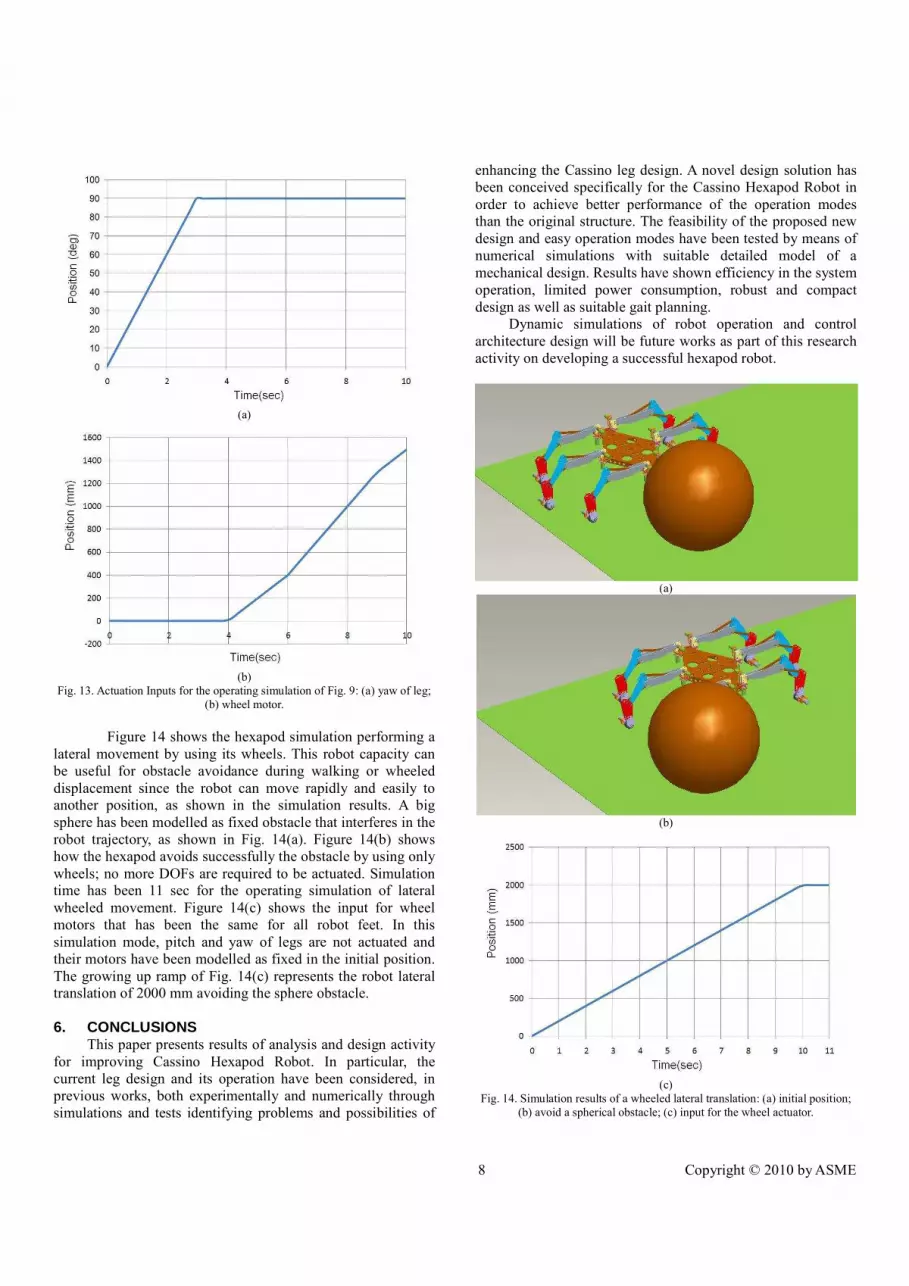
Figure 14 shows the hexapod simulation performing a
lateral movement by using its wheels. This robot capacity can
be useful for obstacle avoidance during walking or wheeled
displacement since the robot can move rapidly and easily to
another position, as shown in the simulation results. A big
sphere has been modelled as fixed obstacle that interferes in the
robot trajectory, as shown in Fig. 14(a). Figure 14(b) shows
how the hexapod avoids successfully the obstacle by using only
wheels; no more DOFs are required to be actuated. Simulation
time has been 11 sec for the operating simulation of lateral
wheeled movement. Figure 14(c) shows the input for wheel
motors that has been the same for all robot feet. In this
simulation mode, pitch and yaw of legs are not actuated and
their motors have been modelled as fixed in the initial position.
The growing up ramp of Fig. 14(c) represents the robot lateral
translation of 2000 mm avoiding the sphere obstacle.
6. CONCLUSIONS This paper presents results of analysis and design activity
for improving Cassino Hexapod Robot. In particular, the
current leg design and its operation have been considered, in
previous works, both experimentally and numerically through
simulations and tests identifying problems and possibilities of
enhancing the Cassino leg design. A novel design solution has
been conceived specifically for the Cassino Hexapod Robot in
order to achieve better performance of the operation modes
than the original structure. The feasibility of the proposed new
design and easy operation modes have been tested by means of
numerical simulations with suitable detailed model of a
mechanical design. Results have shown efficiency in the system
operation, limited power consumption, robust and compact
design as well as suitable gait planning.
Dynamic simulations of robot operation and control
architecture design will be future works as part of this research
activity on developing a successful hexapod robot.
(a)
(b)
(c)
Fig. 14. Simulation results of a wheeled lateral translation: (a) initial position;
(b) avoid a spherical obstacle; (c) input for the wheel actuator.

9 Copyright © 2010 by ASME
7. REFERENCES 1. Berns, K., 2009, “Walking Machine Catalogue”,
Available: http://www.walking-machines.org/.
2. Raibert, M., Blankerpoor, K., Nelson, G., Playter, R.
and BigDog Team, 2008, “BigDog, the Rough-Terrain
Quadruped Robot”, World Congress of the
International Federation of Automatic Control, Seoul,
pp. 10822 - 18025.
3. MIT Computer Science and Aritficial Intelligent Lab.,
2009, http://www.ai.mit.edu/projects/boadicea/ boadic
ea.html.
4. Dzhantimrov, J., Palis, A., Schmucker, B., Telesh, M.
and Zavgorodniy, B., 2007, “HIL/SIL by Development
of a Six Legged Robot SLAIR2”, International
Conference on Climbing and Walking Robots
CLAWAR, Singapore, pp 652-661.
5. Heverly, M. and Matthews, J., 2008, “A Wheel-on-
limb Rover for Lunar Operation”, Symposium on AI,
Robotics and Automation in Space, Los Angeles, pp.
340-344.
6. Carbone, G. and Ceccarelli, M., 2004, “A Mechanical
Design of a Low-Cost Easy-Operation
Anthropomorphic Wheeled Leg for Walking
Machines”, International Journal Robotica Manager,
9(2), pp. 3 - 8.
7. Chakraborty, N. and Ghosal, A., 2004, “Kinematics of
Wheeled Mobile Robots on Uneven Terrain”,
Mechanism and Machine Theory, 39, pp. 1273 – 1287.
8. Carbone, G. and Ceccarelli, M., 2005, “Legged
Robotic Systems”, Cutting Edge Robotics ARS
Scientific Book, Wien, pp. 553 – 76.
9. Zhao, Y. S., Lu, L., Zhao, T. S., Du, Y. H. and Huang,
Z., 2000, “Dynamic Performance Analysis of Six-
Legged Walking Machines”, Mechanism and Machine
Theory, 35(1), pp.155 – 63.
10. Zielinska, T. and Heng, J., 2002, “Development of a
Walking Machine: Mechanical Design and Control
Problems”, Mechatronics, 12(5), pp. 737 – 54.
11. Carbone, G., Shrot, A. and Ceccarelli, M., 2007,
“Operation Strategy for a Low-Cost Easy-Operation
Cassino Hexapod”, Applied Bionics and
Biomechanics, 4(4), pp. 159-156.
12. Hopkin, S. P. and Read, H. J, 1992, “The Biology of Millipedes”, OXFORD University press, New York,
pp. 233.
13. Nava Rodríguez, N. E., Carbone, G. and Ceccarelli, M., 2006, “Optimal Design of Driven Mechanism in a
1-DOF Anthropomorphic Finger”, Mechanism and
Machine Theory, 41, pp. 897-911.
14. Smith, S. G., 2008, Pro/ENGINEER Wildfire 3.0
Update Manual for Wildfire 2.0 Users.
15. SKF homepage, 2009, www.skf.com.
16. Faulhaber Homepage, 2008, DC-Motors, www.faulhab
er-group.com.
17. Cigola, M., Pelliccio, A., Salotto, O., Carbone, G..,
Ottaviano, E. and Ceccarelli, M., 2005, “Application
of Robots for inspection and restoration of Historical
sites”, International Symposium on Automation and
Robotics in Construction, Ferrara, paper 37.


