file structuresnu-oopsla lab1 chap3. secondary storage and system software 서울대학교...
TRANSCRIPT
File Structure SNU-OOPSLA Lab 1
Chap3.Chap3. Secondary Storage Secondary Storage and System Software and System Software
서울대학교 컴퓨터공학과객체지향시스템연구실(SNU-OOPSLA-LAB)
김 형 주 교수
File Structures by Folk, Zoellick, and Ricarrdi
File Structure SNU-OOPSLA Lab 2
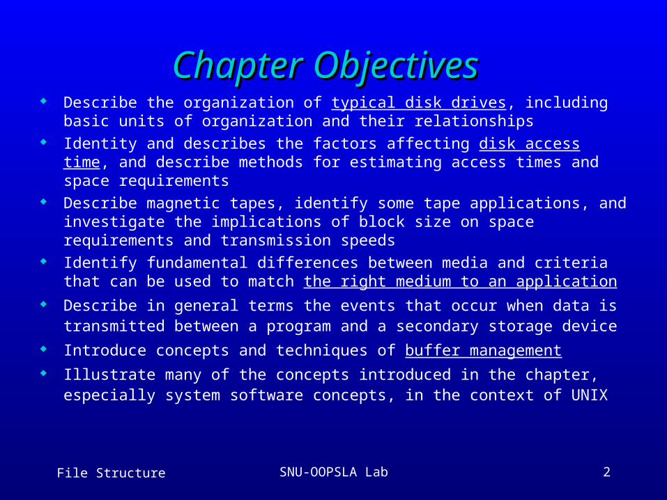
Chapter ObjectivesChapter Objectives Describe the organization of typical disk drives, including basic units of
organization and their relationships Identity and describes the factors affecting disk access time, and describe
methods for estimating access times and space requirements Describe magnetic tapes, identify some tape applications, and investigate
the implications of block size on space requirements and transmission speeds
Identify fundamental differences between media and criteria that can be used to match the right medium to an application
Describe in general terms the events that occur when data is transmitted between a program and a secondary storage device
Introduce concepts and techniques of buffer management Illustrate many of the concepts introduced in the chapter, especially system
software concepts, in the context of UNIX
File Structure SNU-OOPSLA Lab 3
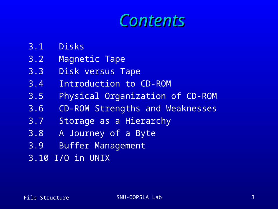
ContentsContents3.1 Disks
3.2 Magnetic Tape
3.3 Disk versus Tape
3.4 Introduction to CD-ROM
3.5 Physical Organization of CD-ROM
3.6 CD-ROM Strengths and Weaknesses
3.7 Storage as a Hierarchy
3.8 A Journey of a Byte
3.9 Buffer Management
3.10 I/O in UNIX
File Structure SNU-OOPSLA Lab 4
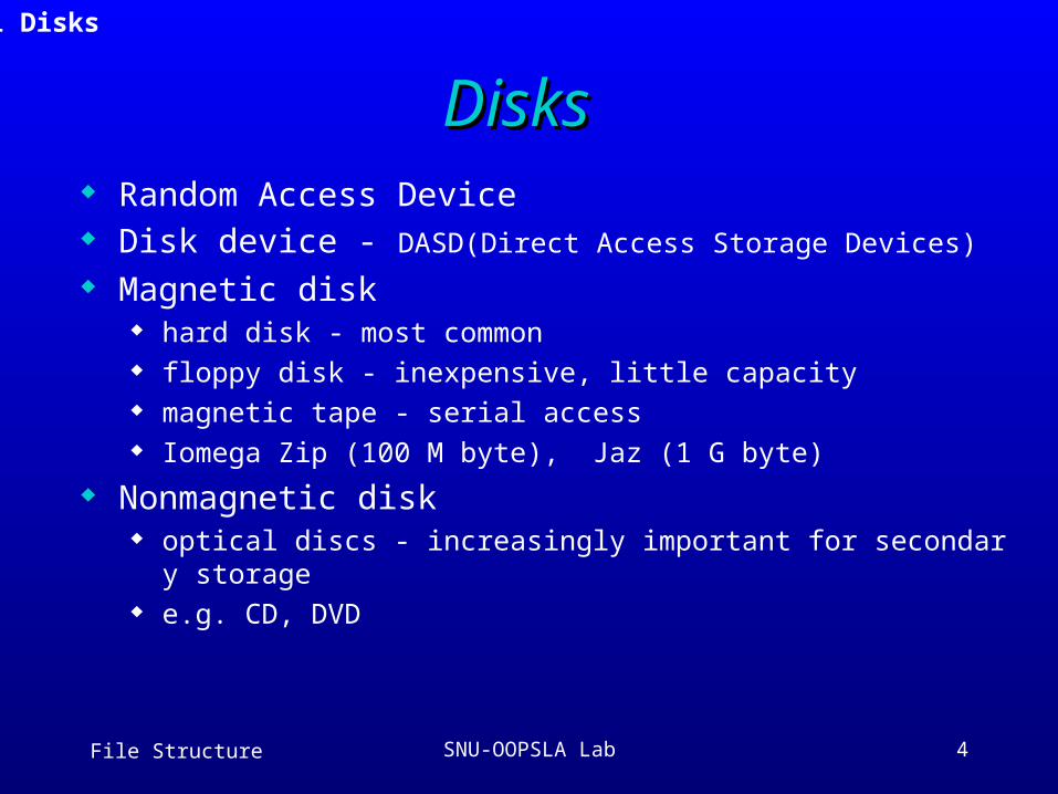
DisksDisks Random Access Device Disk device - DASD(Direct Access Storage Devices)
Magnetic disk hard disk - most common floppy disk - inexpensive, little capacity magnetic tape - serial access Iomega Zip (100 M byte), Jaz (1 G byte)
Nonmagnetic disk optical discs - increasingly important for secondary storage e.g. CD, DVD
3.1 Disks
File Structure SNU-OOPSLA Lab 5
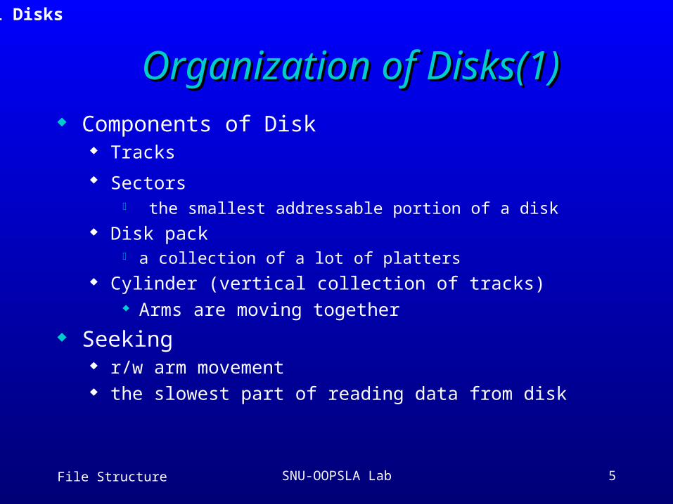
Organization of Disks(1)Organization of Disks(1) Components of Disk
Tracks
Sectors the smallest addressable portion of a disk
Disk pack a collection of a lot of platters
Cylinder (vertical collection of tracks) Arms are moving together
Seeking r/w arm movement the slowest part of reading data from disk
3.1 Disks
File Structure SNU-OOPSLA Lab 6
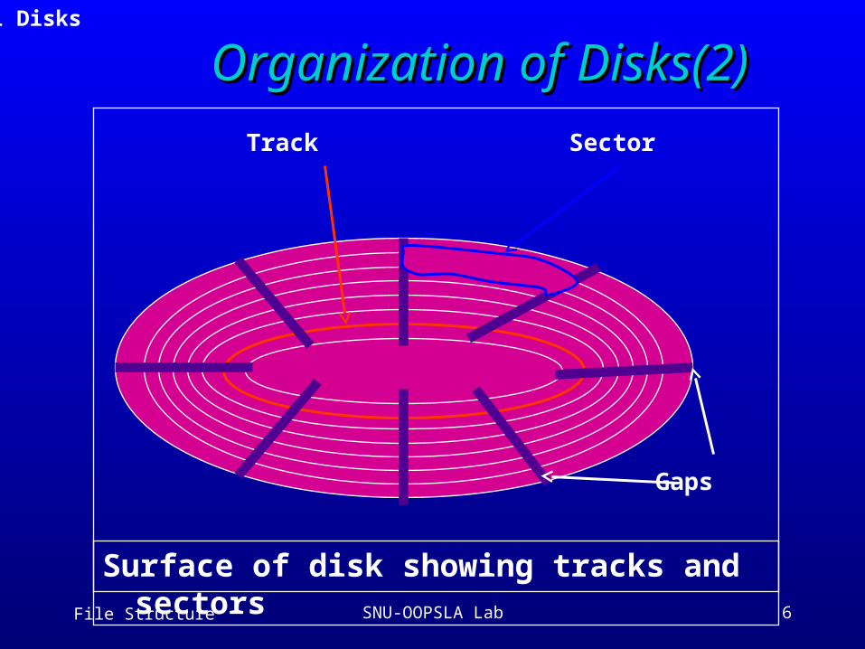
Organization of Disks(2)Organization of Disks(2)
Track Sector
Gaps
Surface of disk showing tracks and sectors
3.1 Disks
File Structure SNU-OOPSLA Lab 7
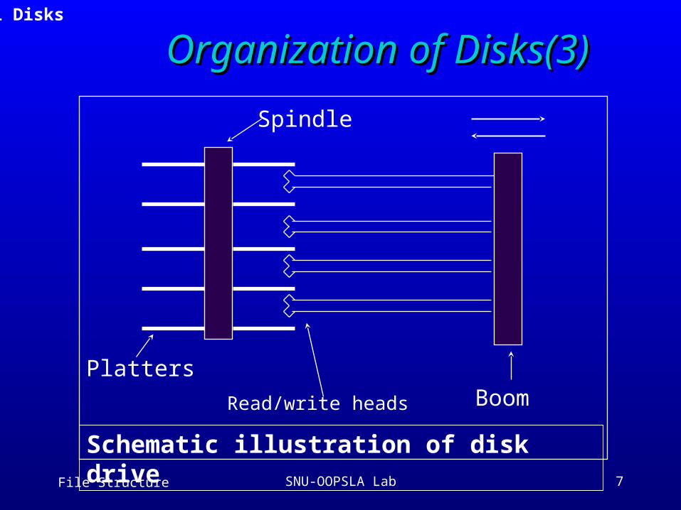
BoomRead/write heads
Spindle
Platters
Schematic illustration of disk drive
3.1 Disks
Organization of Disks(3)Organization of Disks(3)
File Structure SNU-OOPSLA Lab 8
Estimating Capacities(1)Estimating Capacities(1)
Cylinder --> Track --> Sector --> Byte Track capacity
= # of sectors per track * bytes per sector
Cylinder capacity = # of tracks per cylinder * track capacity
Drive capacity = # of cylinders * cylinder capacity
** Inner track, Outer track? Same capacity?
3.1 Disks
File Structure SNU-OOPSLA Lab 9
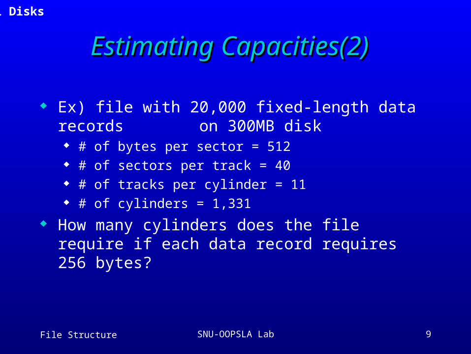
Estimating Capacities(2)Estimating Capacities(2)
Ex) file with 20,000 fixed-length data records on 300MB disk
# of bytes per sector = 512 # of sectors per track = 40 # of tracks per cylinder = 11 # of cylinders = 1,331
How many cylinders does the file require if each data record requires 256 bytes?
3.1 Disks
File Structure SNU-OOPSLA Lab 10
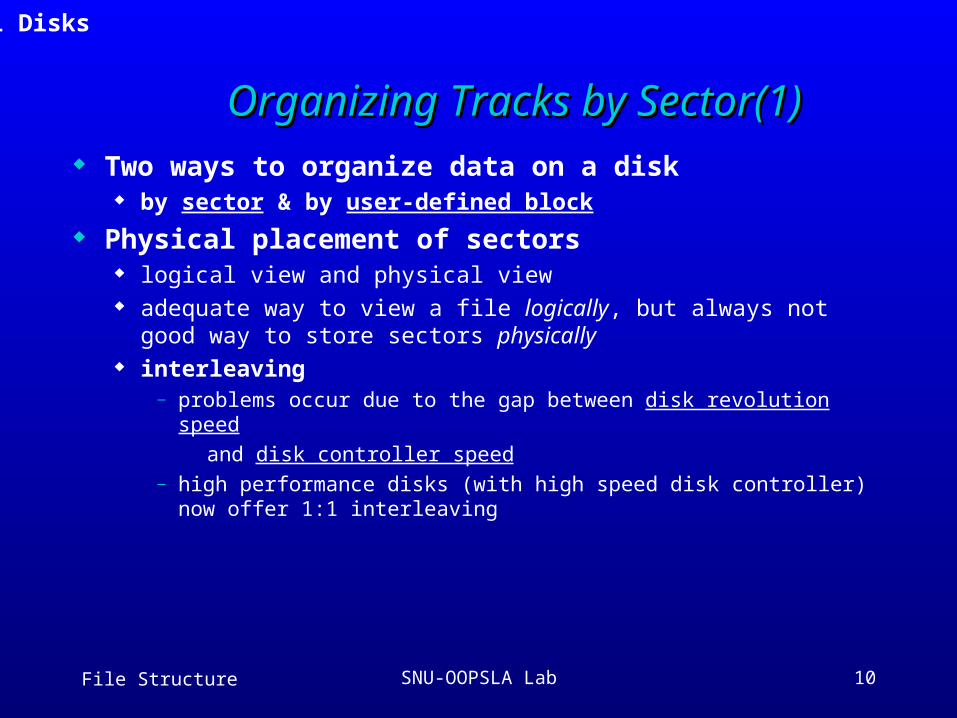
Organizing Tracks by Sector(1)Organizing Tracks by Sector(1) Two ways to organize data on a disk
by sector & by user-defined block
Physical placement of sectors logical view and physical view adequate way to view a file logically, but always not good way to
store sectors physically interleaving
— problems occur due to the gap between disk revolution speed
and disk controller speed— high performance disks (with high speed disk controller) now offer
1:1 interleaving
3.1 Disks
File Structure SNU-OOPSLA Lab 11
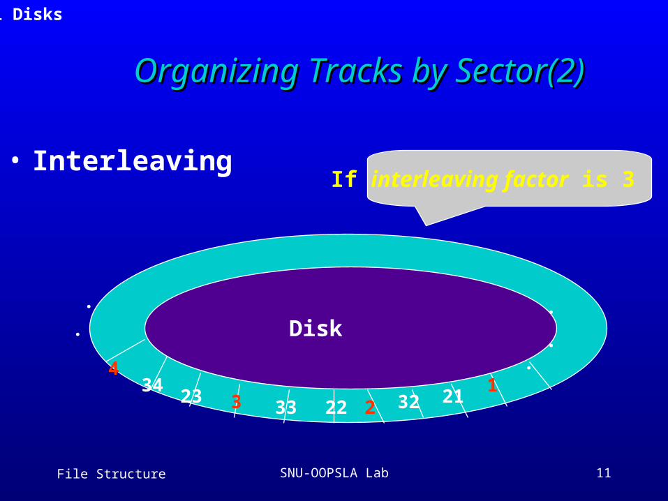
123
4
2122
23 323334
If interleaving factor is 3
..
..
.
Disk
3.1 Disks
• Interleaving
Organizing Tracks by Sector(2)Organizing Tracks by Sector(2)
File Structure SNU-OOPSLA Lab 12
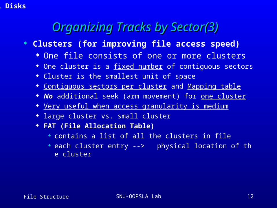
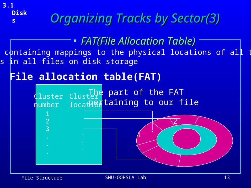
Organizing Tracks by Sector(3)Organizing Tracks by Sector(3) Clusters (for improving file access speed)
One file consists of one or more clusters One cluster is a fixed number of contiguous sectors Cluster is the smallest unit of space Contiguous sectors per cluster and Mapping table No additional seek (arm movement) for one cluster Very useful when access granularity is medium large cluster vs. small cluster FAT (File Allocation Table)
contains a list of all the clusters in file each cluster entry --> physical location of the cluster
3.1 Disks
File Structure SNU-OOPSLA Lab 13
• FAT(File Allocation Table) FAT(File Allocation Table) - A table containing mappings to the physical locations of all the clusters in all files on disk storage
Cluster number
Clusterlocation
123...
File allocation table(FAT)
The part of the FAT pertaining to our file
.
.
.
2
1
3.1 Disks
Organizing Tracks by Sector(3)Organizing Tracks by Sector(3)
File Structure SNU-OOPSLA Lab 14
Organizing Tracks by Sector(4)Organizing Tracks by Sector(4)
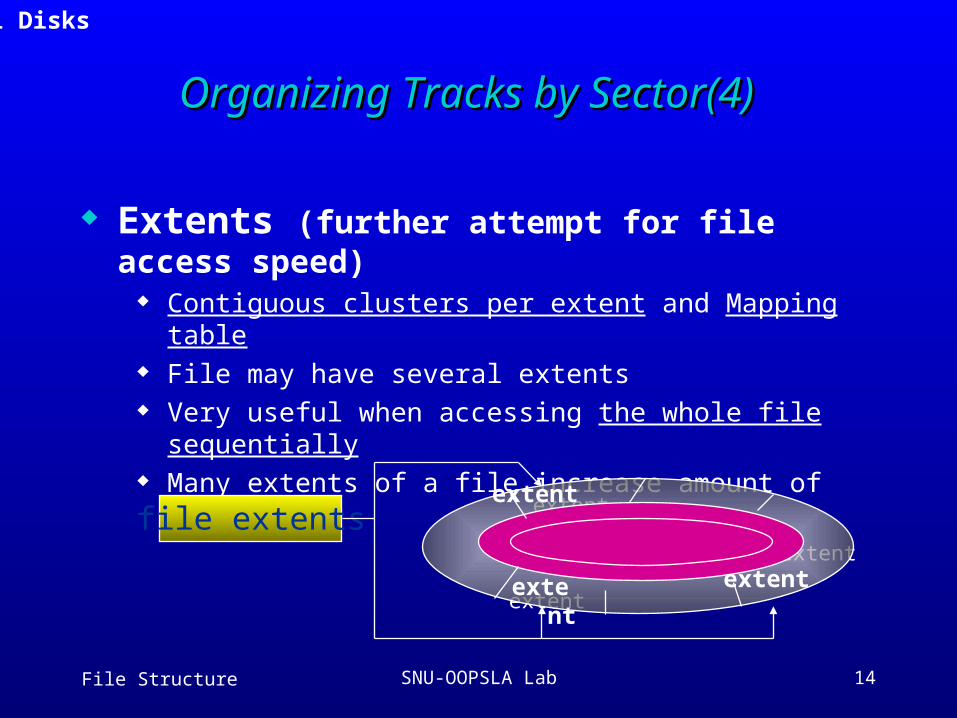
Extents (further attempt for file access speed) Contiguous clusters per extent and Mapping table File may have several extents Very useful when accessing the whole file sequentially Many extents of a file increase amount of seeking
3.1 Disks
file extents extent
extent
extent
extent
extent extent
File Structure SNU-OOPSLA Lab 15
Organizing Tracks by Sector(5)Organizing Tracks by Sector(5)
Fragmentation the space that goes unused within a cluster, block, track, or
other unit of physical storage internal fragmentation: loss of space within a sector or cluster trade-offs in use of large cluster sizes ex) size of sector is 512 bytes and size of all r
ecords in file is 300 bytes we may enforce one record / sector we may allow span sectors
3.1 Disks
File Structure SNU-OOPSLA Lab 16
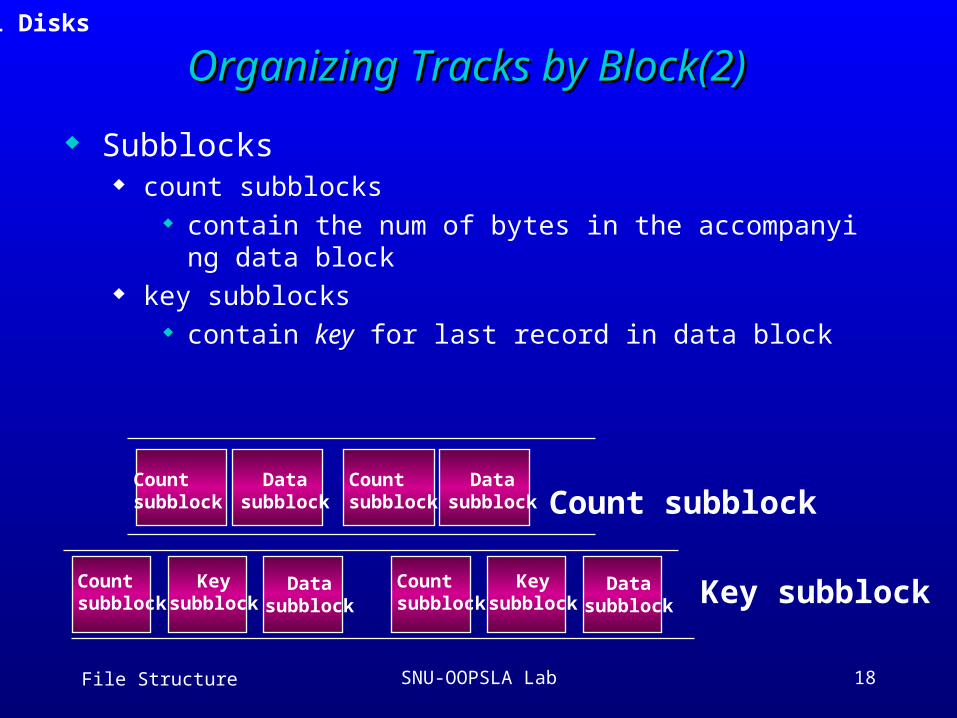
Organizing Tracks by Block(1)Organizing Tracks by Block(1)
User-defined size of blocks can be fixed or variable No sector spanning ==> No internal fragmentation Blocking factor
the number of records that are to be stored in each block
In block-addressing, each block of data is accompanied by one or more subblocks containing extra information about the data block
Note: the “block” has a different meaning in the context of the UNIX I/O system
3.1 Disks
File Structure SNU-OOPSLA Lab 17
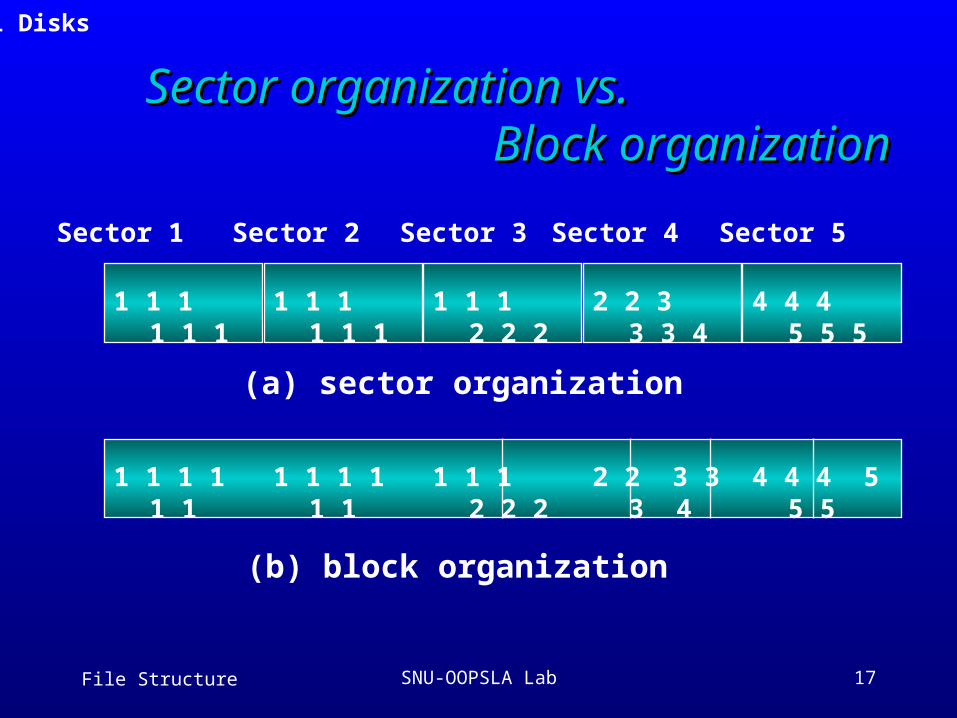
Sector organization vs.Sector organization vs. Block organization Block organization
1 1 1 1 1 1
1 1 1 1 1 1
1 1 1 2 2 2
2 2 3 3 3 4
4 4 4 5 5 5
Sector 1 Sector 2 Sector 3 Sector 4 Sector 5
(a) sector organization
(b) block organization
3.1 Disks
1 1 1 1 1 1 1 1 1 1 1 1 1 1 1 2 2 2
2 2 3 3 3 4
4 4 4 5 5 5
File Structure SNU-OOPSLA Lab 18
Organizing Tracks by Block(2)Organizing Tracks by Block(2)
Subblocks count subblocks
contain the num of bytes in the accompanying data block key subblocks
contain key for last record in data block
Countsubblock Count subblock
Key subblock
Datasubblock
Countsubblock
Datasubblock
Countsubblock
Keysubblock
Datasubblock
Countsubblock
Keysubblock
Datasubblock
3.1 Disks
File Structure SNU-OOPSLA Lab 19
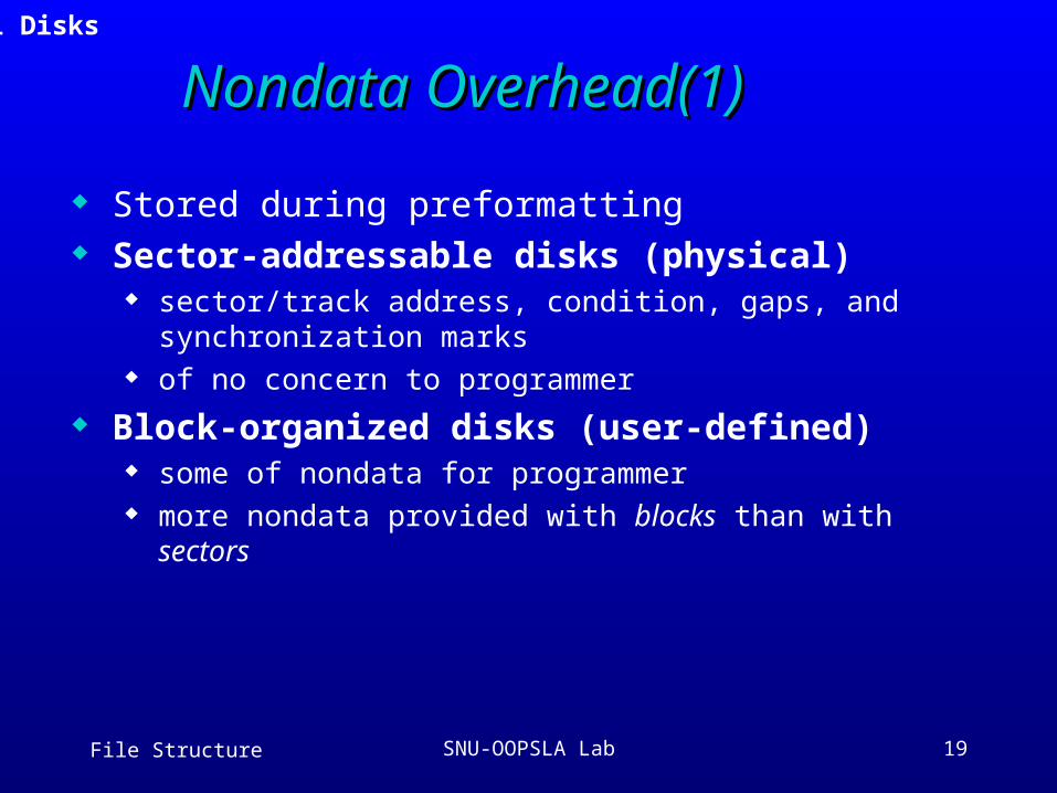
Nondata Overhead(1)Nondata Overhead(1)
Stored during preformatting Sector-addressable disks (physical)
sector/track address, condition, gaps, and synchronization marks
of no concern to programmer
Block-organized disks (user-defined) some of nondata for programmer more nondata provided with blocks than with sectors
3.1 Disks
File Structure SNU-OOPSLA Lab 20
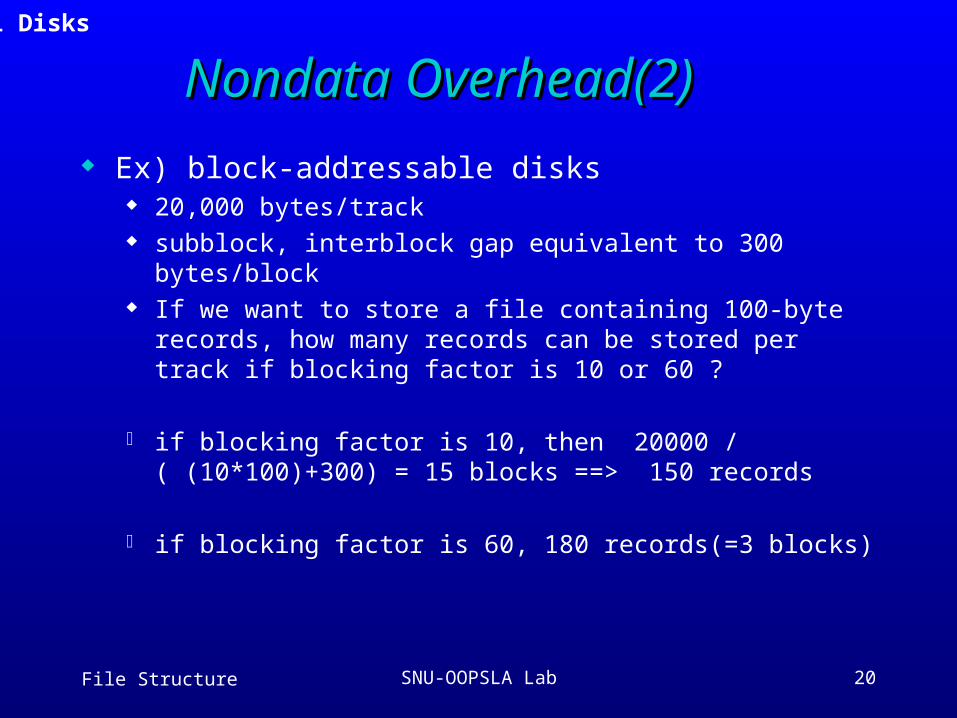
Nondata Overhead(2)Nondata Overhead(2)
Ex) block-addressable disks 20,000 bytes/track subblock, interblock gap equivalent to 300 bytes/block If we want to store a file containing 100-byte records, how
many records can be stored per track if blocking factor is 10 or 60 ?
if blocking factor is 10, then 20000 / ( (10*100)+300) = 15 blocks ==> 150 records
if blocking factor is 60, 180 records(=3 blocks)
3.1 Disks
File Structure SNU-OOPSLA Lab 21
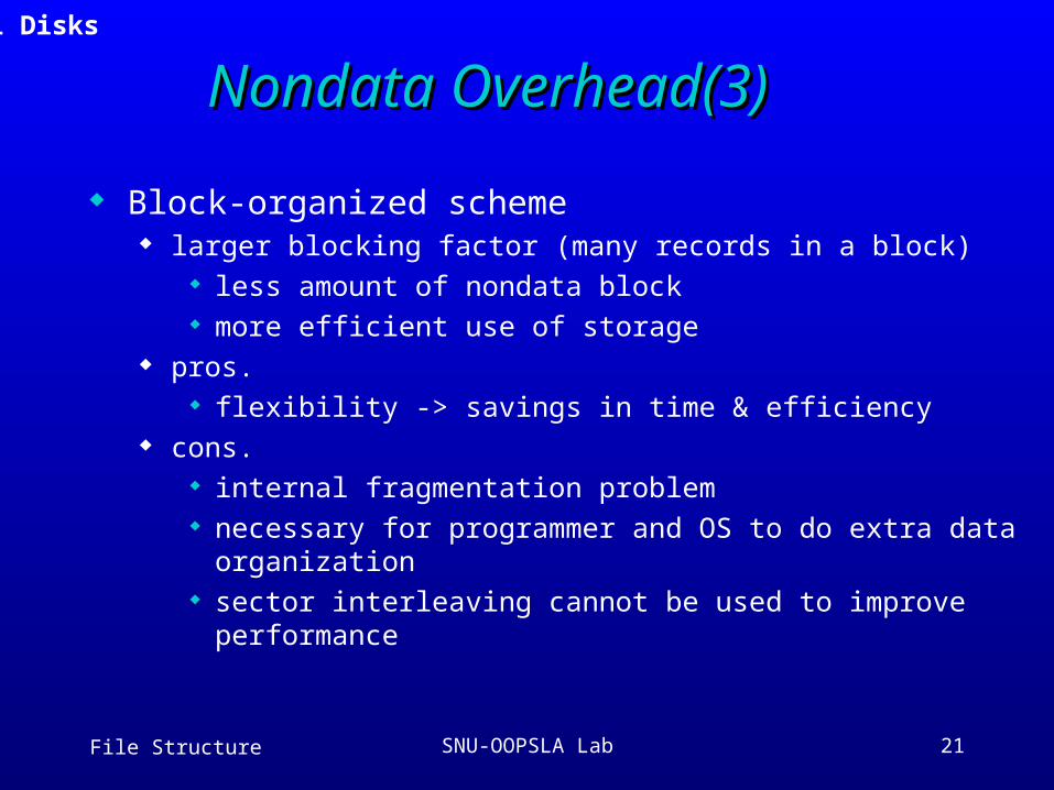
Nondata Overhead(3)Nondata Overhead(3)
Block-organized scheme larger blocking factor (many records in a block)
less amount of nondata block more efficient use of storage
pros. flexibility -> savings in time & efficiency
cons. internal fragmentation problem necessary for programmer and OS to do extra data
organization sector interleaving cannot be used to improve performance
3.1 Disks
File Structure SNU-OOPSLA Lab 22
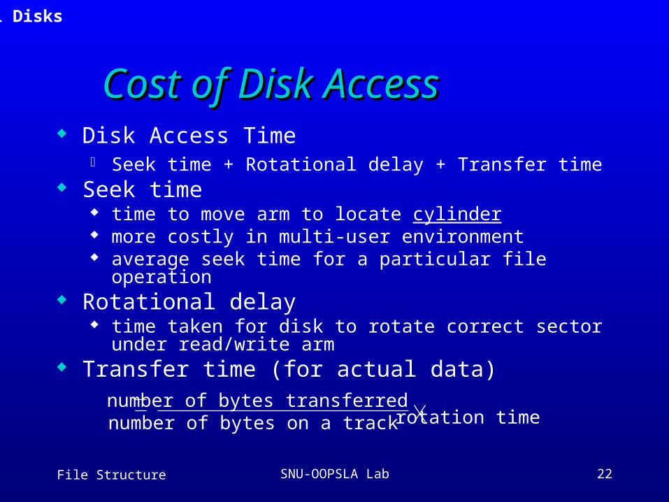
Cost of Disk AccessCost of Disk Access Disk Access Time
Seek time + Rotational delay + Transfer time Seek time
time to move arm to locate cylinder more costly in multi-user environment average seek time for a particular file operation
Rotational delay time taken for disk to rotate correct sector under read/write
arm Transfer time (for actual data)
number of bytes transferrednumber of bytes on a track rotation time
3.1 Disks
File Structure SNU-OOPSLA Lab 23
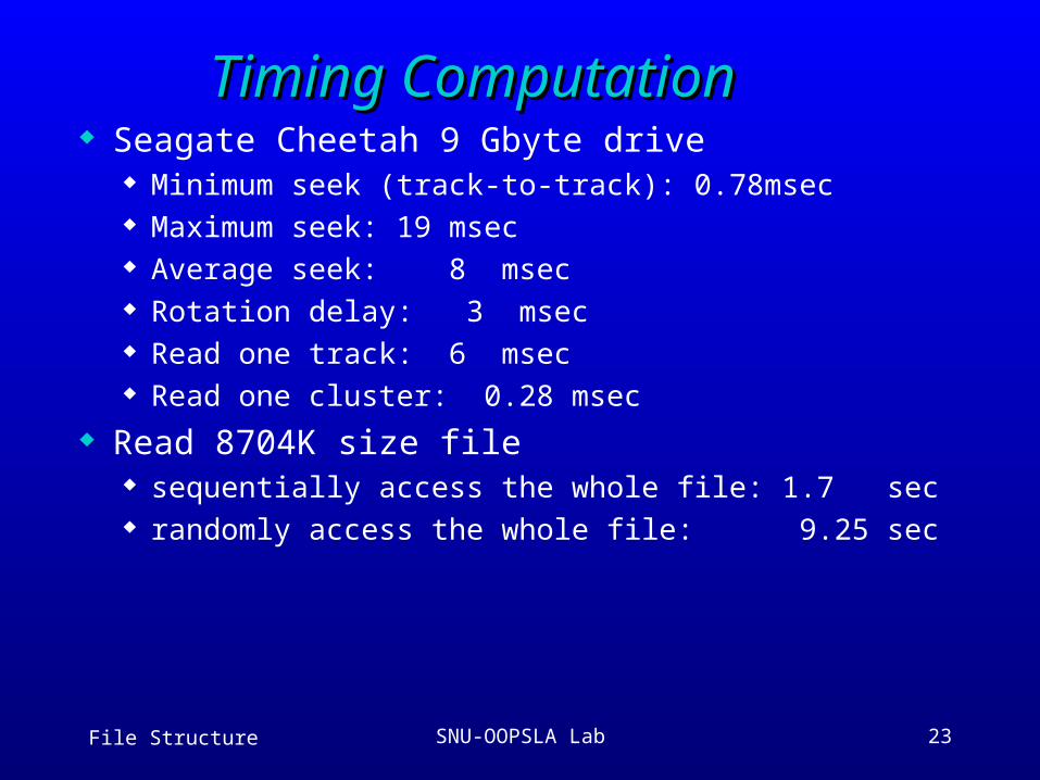
Timing ComputationTiming Computation Seagate Cheetah 9 Gbyte drive
Minimum seek (track-to-track): 0.78msec Maximum seek: 19 msec Average seek: 8 msec Rotation delay: 3 msec Read one track: 6 msec Read one cluster: 0.28 msec
Read 8704K size file sequentially access the whole file: 1.7 sec randomly access the whole file: 9.25 sec
File Structure SNU-OOPSLA Lab 24
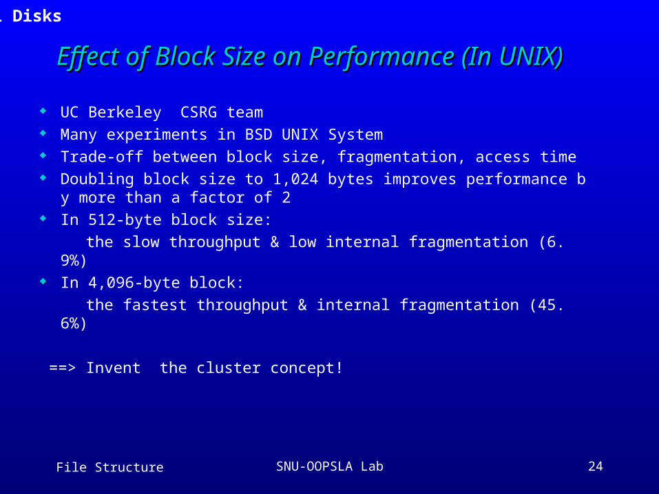
Effect of Block Size on Performance (In UNIX) Effect of Block Size on Performance (In UNIX)
UC Berkeley CSRG team Many experiments in BSD UNIX System Trade-off between block size, fragmentation, access time Doubling block size to 1,024 bytes improves performance by mo
re than a factor of 2 In 512-byte block size:
the slow throughput & low internal fragmentation (6.9%) In 4,096-byte block:
the fastest throughput & internal fragmentation (45.6%)
==> Invent the cluster concept!
3.1 Disks
File Structure SNU-OOPSLA Lab 25
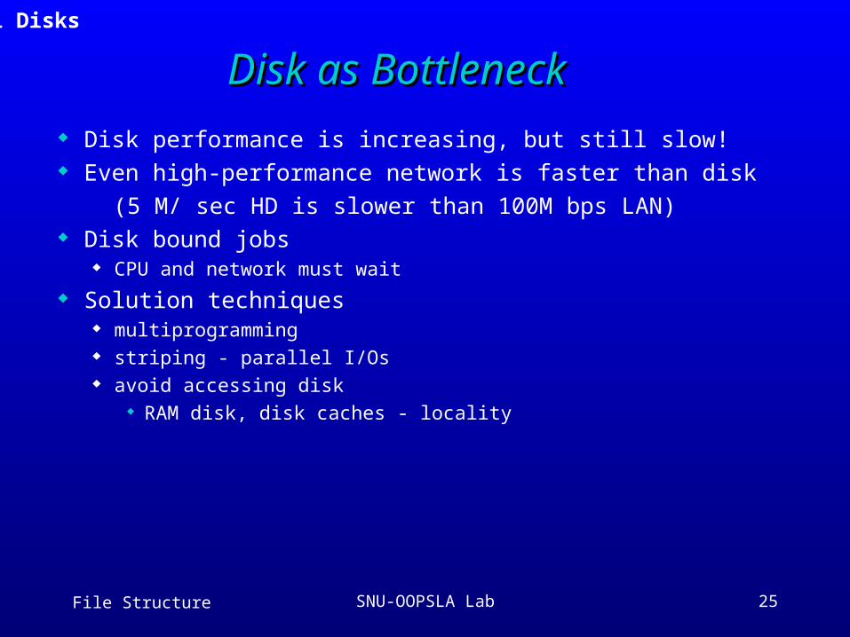
Disk as BottleneckDisk as Bottleneck
Disk performance is increasing, but still slow! Even high-performance network is faster than disk
(5 M/ sec HD is slower than 100M bps LAN) Disk bound jobs
CPU and network must wait
Solution techniques multiprogramming striping - parallel I/Os avoid accessing disk
RAM disk, disk caches - locality
3.1 Disks
File Structure SNU-OOPSLA Lab 26
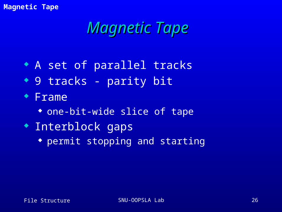
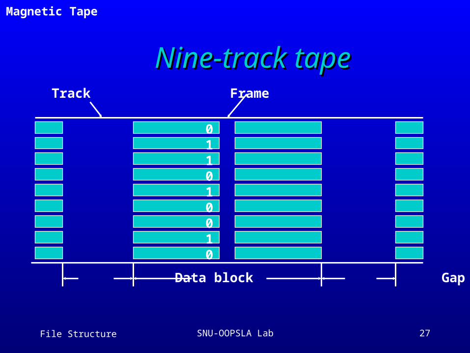
Magnetic TapeMagnetic Tape
A set of parallel tracks 9 tracks - parity bit Frame
one-bit-wide slice of tape
Interblock gaps permit stopping and starting
3.2 Magnetic Tape
File Structure SNU-OOPSLA Lab 27
Nine-track tapeNine-track tapeTrack Frame
011010010
Gap Data block Gap
3.2 Magnetic Tape
File Structure SNU-OOPSLA Lab 28
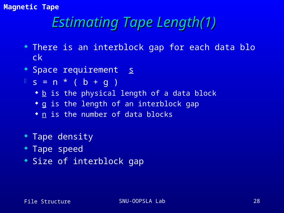
Estimating Tape Length(1)Estimating Tape Length(1)
There is an interblock gap for each data block Space requirement s s = n * ( b + g )
b is the physical length of a data block g is the length of an interblock gap n is the number of data blocks
Tape density Tape speed Size of interblock gap
3.2 Magnetic Tape
File Structure SNU-OOPSLA Lab 29
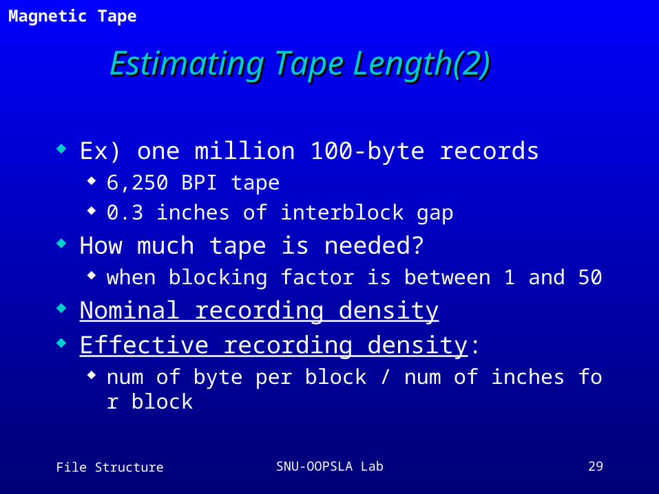
Estimating Tape Estimating Tape Length(2)Length(2)
Ex) one million 100-byte records 6,250 BPI tape 0.3 inches of interblock gap
How much tape is needed? when blocking factor is between 1 and 50
Nominal recording density Effective recording density:
num of byte per block / num of inches for block
3.2 Magnetic Tape
File Structure SNU-OOPSLA Lab 30
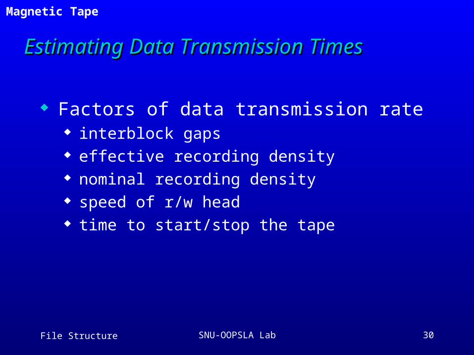
Estimating Data Transmission TimesEstimating Data Transmission Times
Factors of data transmission rate interblock gaps effective recording density nominal recording density speed of r/w head time to start/stop the tape
3.2 Magnetic Tape
File Structure SNU-OOPSLA Lab 31
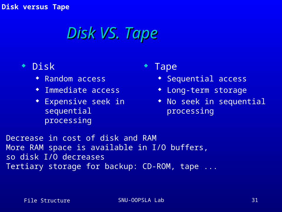
Disk VS. TapeDisk VS. Tape
Disk Random access Immediate access Expensive seek in
sequential processing
Tape Sequential access Long-term storage No seek in sequential
processing
Decrease in cost of disk and RAM More RAM space is available in I/O buffers, so disk I/O decreases Tertiary storage for backup: CD-ROM, tape ...
3.3 Disk versus Tape
File Structure SNU-OOPSLA Lab 32
Introduction to CD-ROMIntroduction to CD-ROM
3.4 Introduction to CD-ROM
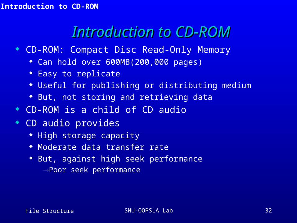
CD-ROM: Compact Disc Read-Only Memory Can hold over 600MB(200,000 pages) Easy to replicate Useful for publishing or distributing medium But, not storing and retrieving data
CD-ROM is a child of CD audio CD audio provides
High storage capacity Moderate data transfer rate But, against high seek performance
Poor seek performance
File Structure SNU-OOPSLA Lab 33
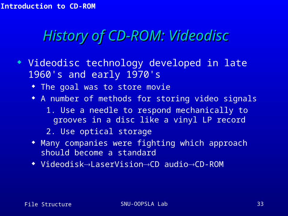
History of CD-ROM: VideodiscHistory of CD-ROM: Videodisc
Videodisc technology developed in late 1960's and early 1970's The goal was to store movie A number of methods for storing video signals
1. Use a needle to respond mechanically to grooves in a disc like a vinyl LP record
2. Use optical storage Many companies were fighting which approach should become a
standard VideodiskLaserVisionCD audioCD-ROM
3.4 Introduction to CD-ROM
File Structure SNU-OOPSLA Lab 34
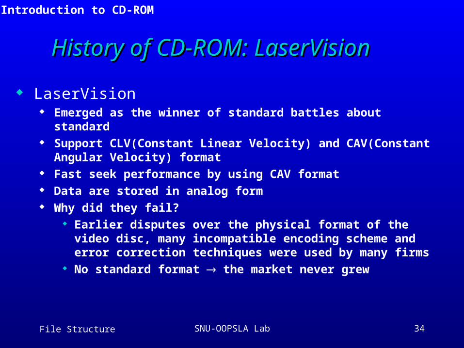
History of CD-ROM: LaserVisionHistory of CD-ROM: LaserVision
LaserVision Emerged as the winner of standard battles about standard Support CLV(Constant Linear Velocity) and CAV(Constant Angular
Velocity) format Fast seek performance by using CAV format Data are stored in analog form Why did they fail?
Earlier disputes over the physical format of the video disc, many incompatible encoding scheme and error correction techniques were used by many firms
No standard format the market never grew
3.4 Introduction to CD-ROM
File Structure SNU-OOPSLA Lab 35
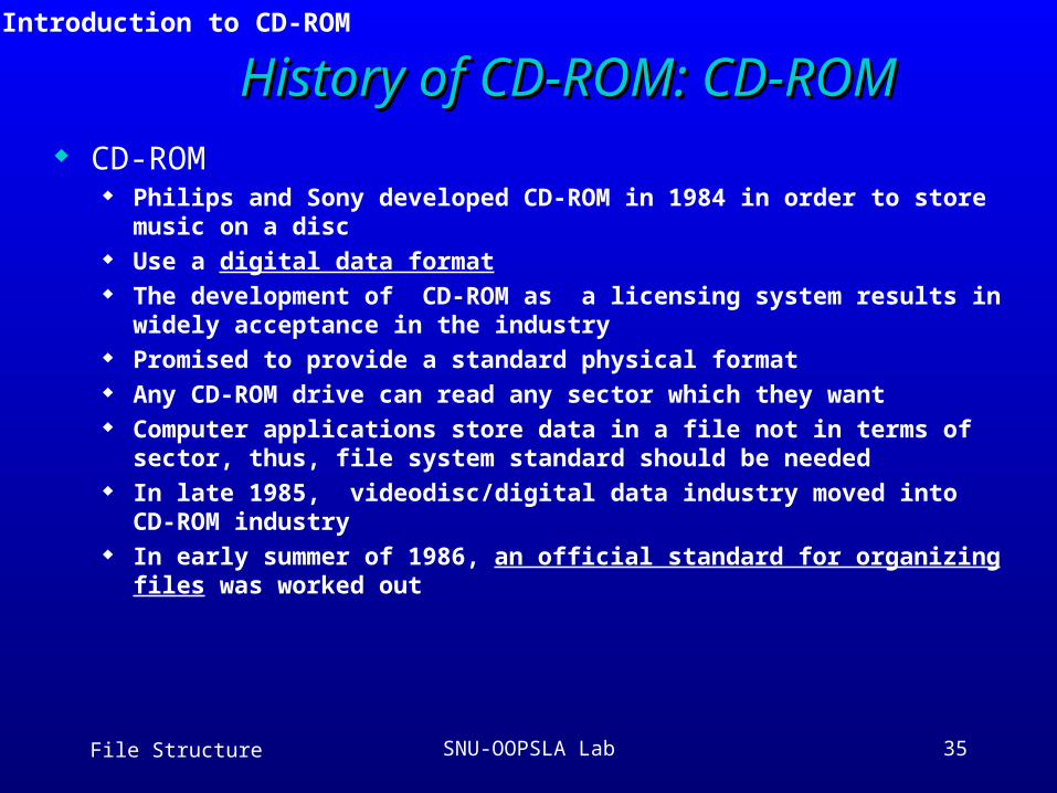
History of CD-ROM: CD-ROMHistory of CD-ROM: CD-ROM CD-ROM
Philips and Sony developed CD-ROM in 1984 in order to store music on a disc
Use a digital data format The development of CD-ROM as a licensing system results in widely
acceptance in the industry Promised to provide a standard physical format Any CD-ROM drive can read any sector which they want Computer applications store data in a file not in terms of sector, thus, file
system standard should be needed In late 1985, videodisc/digital data industry moved into CD-ROM industry In early summer of 1986, an official standard for organizing files was
worked out
3.4 Introduction to CD-ROM
File Structure SNU-OOPSLA Lab 36
3.5 Physical Organization of CD-ROM
Physical Organization of Master DiskPhysical Organization of Master Disk
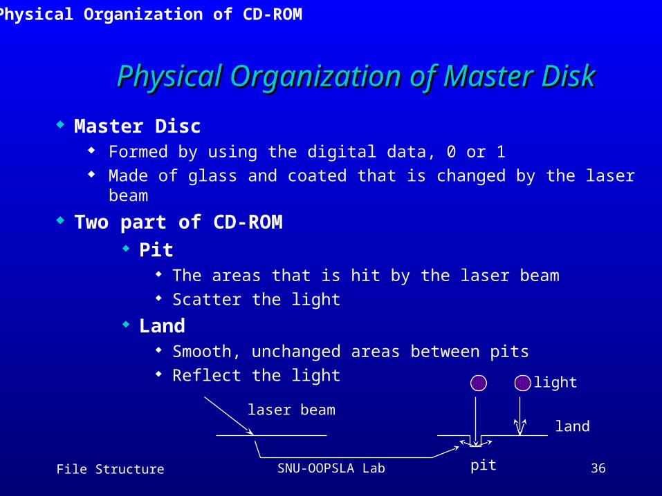
Master Disc Formed by using the digital data, 0 or 1 Made of glass and coated that is changed by the laser beam
Two part of CD-ROM Pit
The areas that is hit by the laser beam Scatter the light
Land Smooth, unchanged areas between pits Reflect the light
laser beam
pit
land
light
File Structure SNU-OOPSLA Lab 37
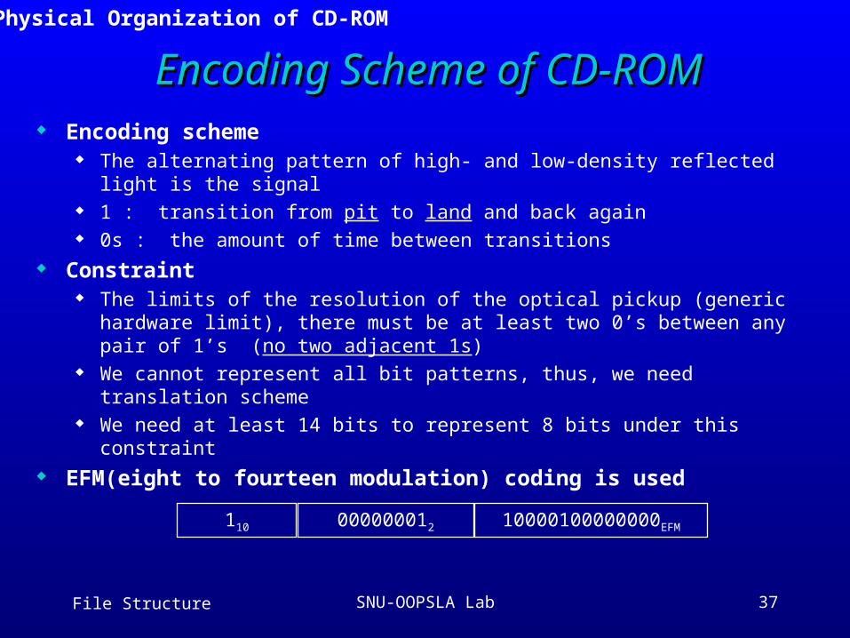
Encoding Scheme of CD-ROMEncoding Scheme of CD-ROM Encoding scheme
The alternating pattern of high- and low-density reflected light is the signal 1 : transition from pit to land and back again 0s : the amount of time between transitions
Constraint The limits of the resolution of the optical pickup (generic hardware limit),
there must be at least two 0’s between any pair of 1’s (no two adjacent 1s)
We cannot represent all bit patterns, thus, we need translation scheme We need at least 14 bits to represent 8 bits under this constraint
EFM(eight to fourteen modulation) coding is used
110 10000100000000EFM000000012
3.5 Physical Organization of CD-ROM
File Structure SNU-OOPSLA Lab 38
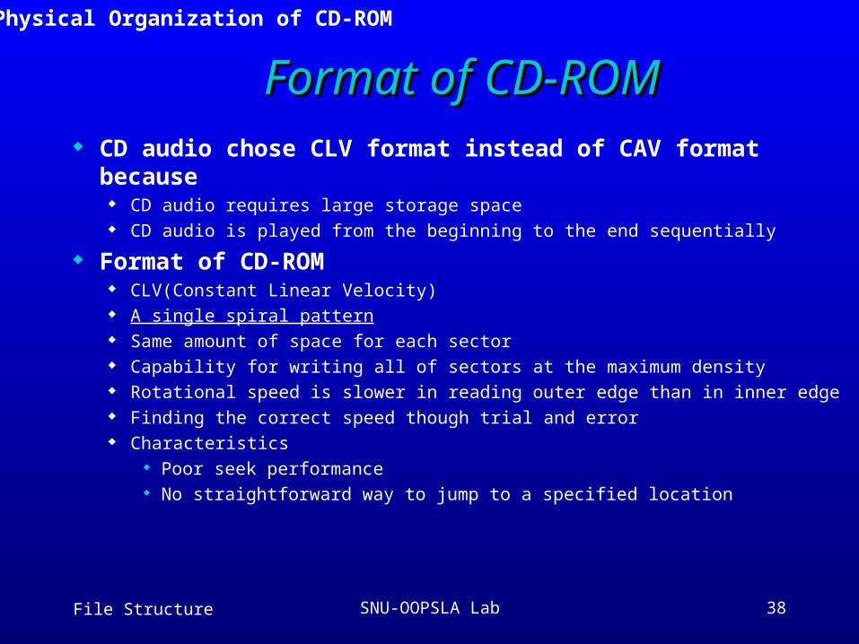
Format of CD-ROMFormat of CD-ROM CD audio chose CLV format instead of CAV format because
CD audio requires large storage space CD audio is played from the beginning to the end sequentially
Format of CD-ROM CLV(Constant Linear Velocity) A single spiral pattern Same amount of space for each sector Capability for writing all of sectors at the maximum density Rotational speed is slower in reading outer edge than in inner edge Finding the correct speed though trial and error Characteristics
Poor seek performance No straightforward way to jump to a specified location
3.5 Physical Organization of CD-ROM
File Structure SNU-OOPSLA Lab 39
Constant Angular Velocity DiskConstant Angular Velocity Disk
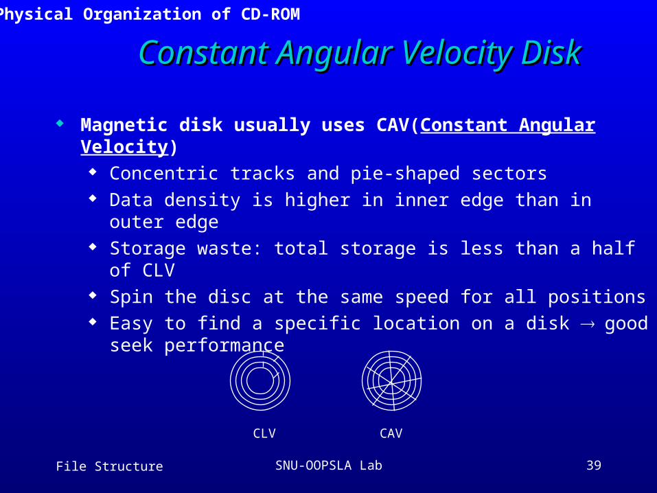
Magnetic disk usually uses CAV(Constant Angular Velocity) Concentric tracks and pie-shaped sectors Data density is higher in inner edge than in outer edge Storage waste: total storage is less than a half of CLV Spin the disc at the same speed for all positions Easy to find a specific location on a disk good seek
performance
CAVCLV
3.5 Physical Organization of CD-ROM
File Structure SNU-OOPSLA Lab 40
Addressing of CD-ROMAddressing of CD-ROM Addressing
Magnetic disk: cylinder/track/sector approach CD-ROM: a sector-addressing scheme
Track density varies thus, each second of playing time on a CD is divided into 75 sectors 75 sectors/sec, 2 Kbytes/sector At least one-hour of playing time Maximum capacity can be calculated: 600 Mbytes
60 min * 60 sec/min * 75 sectors/sec = 270,000 sectors
We address a given sector by referring minutes, second, and sector of play 16:22:34 means 34th sector in the 22nd second in the 16th minutes of play
3.5 Physical Organization of CD-ROM
File Structure SNU-OOPSLA Lab 41
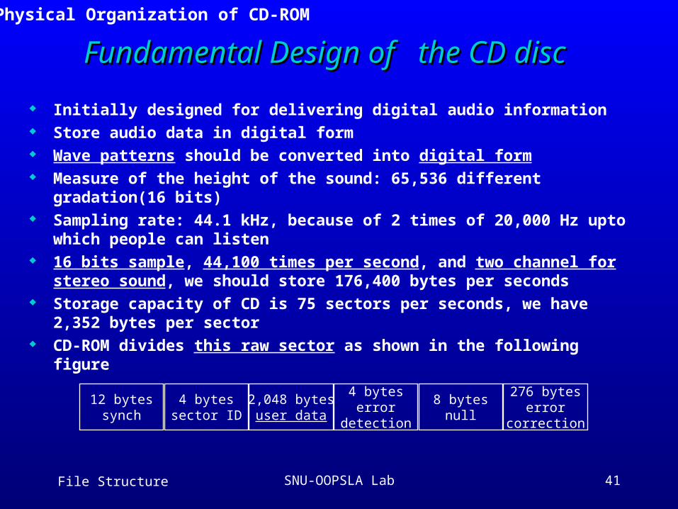
Fundamental Design of the CD discFundamental Design of the CD disc
Initially designed for delivering digital audio information Store audio data in digital form Wave patterns should be converted into digital form Measure of the height of the sound: 65,536 different gradation(16 bits) Sampling rate: 44.1 kHz, because of 2 times of 20,000 Hz upto which
people can listen 16 bits sample, 44,100 times per second, and two channel for stereo
sound, we should store 176,400 bytes per seconds Storage capacity of CD is 75 sectors per seconds, we have 2,352 bytes
per sector CD-ROM divides this raw sector as shown in the following figure
12 bytessynch
4 bytessector ID
2,048 bytesuser data
4 byteserror
detection
8 bytesnull
276 byteserror
correction
3.5 Physical Organization of CD-ROM
File Structure SNU-OOPSLA Lab 42
3.6 CD-ROM Strengths and Weaknesses
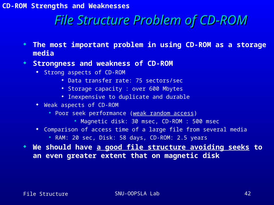
File Structure Problem of CD-ROMFile Structure Problem of CD-ROM
The most important problem in using CD-ROM as a storage media Strongness and weakness of CD-ROM
Strong aspects of CD-ROM Data transfer rate: 75 sectors/sec Storage capacity : over 600 Mbytes Inexpensive to duplicate and durable
Weak aspects of CD-ROM Poor seek performance (weak random access)
Magnetic disk: 30 msec, CD-ROM : 500 msec Comparison of access time of a large file from several media
RAM: 20 sec, Disk: 58 days, CD-ROM: 2.5 years
We should have a good file structure avoiding seeks to an even greater extent that on magnetic disk
File Structure SNU-OOPSLA Lab 43
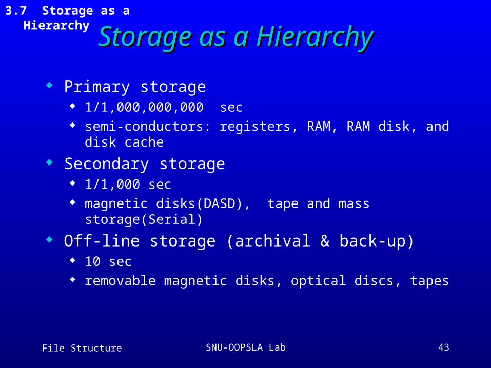
Storage as a HierarchyStorage as a Hierarchy
Primary storage 1/1,000,000,000 sec semi-conductors: registers, RAM, RAM disk, and disk cache
Secondary storage 1/1,000 sec magnetic disks(DASD), tape and mass storage(Serial)
Off-line storage (archival & back-up) 10 sec removable magnetic disks, optical discs, tapes
3.7 Storage as a Hierarchy
File Structure SNU-OOPSLA Lab 44
A Journey of a Byte(1)A Journey of a Byte(1)
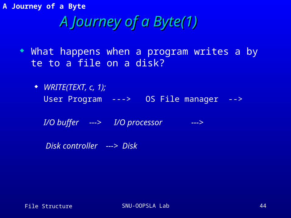
What happens when a program writes a byte to a file on a disk?
WRITE(TEXT, c, 1); User Program ---> OS File manager -->
I/O buffer ---> I/O processor --->
Disk controller ---> Disk
3.8 A Journey of a Byte
File Structure SNU-OOPSLA Lab 45
A Journey of a Byte(2)A Journey of a Byte(2)
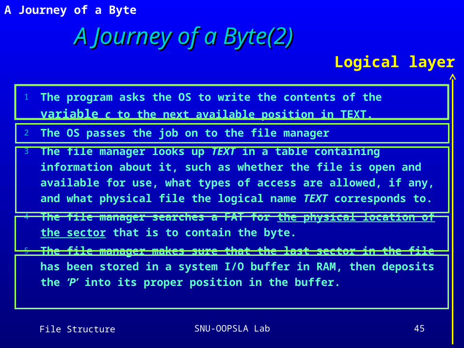
1 The program asks the OS to write the contents of the variable c to the
next available position in TEXT.
2 The OS passes the job on to the file manager
3 The file manager looks up TEXT in a table containing information about it,
such as whether the file is open and available for use, what types of
access are allowed, if any, and what physical file the logical name TEXT
corresponds to.
4 The file manager searches a FAT for the physical location of the sector
that is to contain the byte.
5 The file manager makes sure that the last sector in the file has been
stored in a system I/O buffer in RAM, then deposits the ‘P’ into its proper
position in the buffer.
Logical layer
3.8 A Journey of a Byte
File Structure SNU-OOPSLA Lab 46
A Journey of a Byte(3)A Journey of a Byte(3)
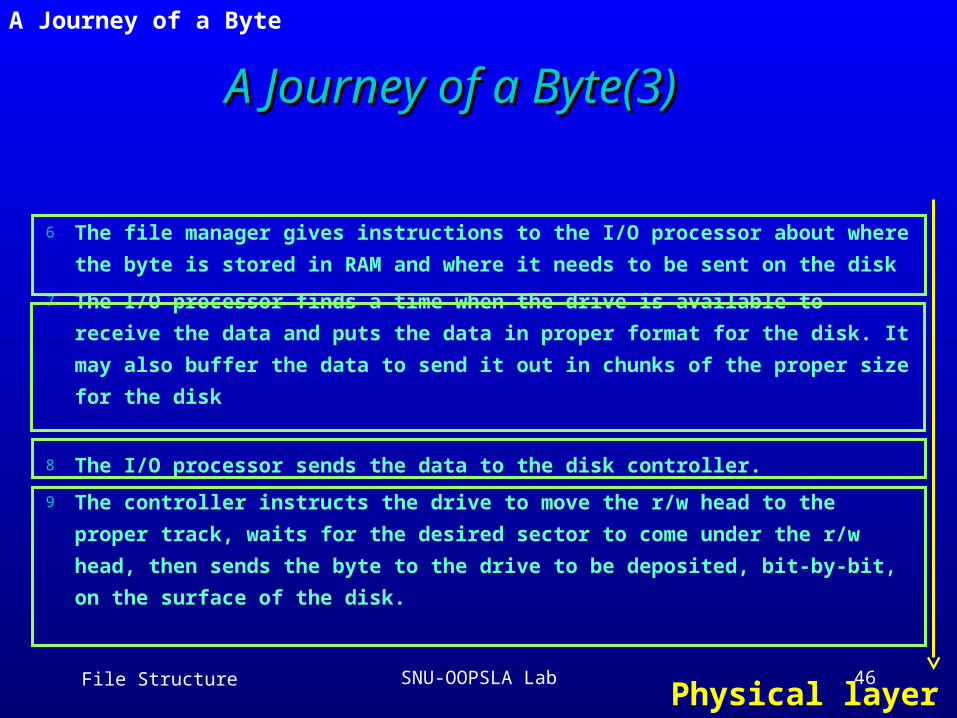
6 The file manager gives instructions to the I/O processor about where the
byte is stored in RAM and where it needs to be sent on the disk
7 The I/O processor finds a time when the drive is available to receive the
data and puts the data in proper format for the disk. It may also buffer the
data to send it out in chunks of the proper size for the disk
8 The I/O processor sends the data to the disk controller.
9 The controller instructs the drive to move the r/w head to the proper track,
waits for the desired sector to come under the r/w head, then sends the
byte to the drive to be deposited, bit-by-bit, on the surface of the disk.
Physical layer
3.8 A Journey of a Byte
File Structure SNU-OOPSLA Lab 47
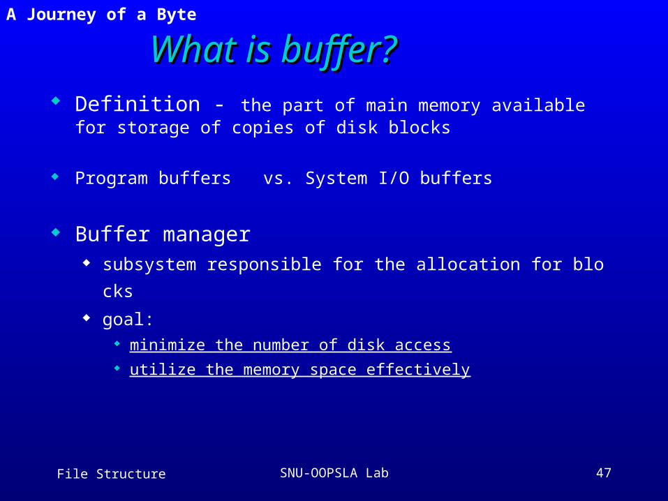
What is buffer?What is buffer? Definition - the part of main memory available for storage of c
opies of disk blocks
Program buffers vs. System I/O buffers
Buffer manager subsystem responsible for the allocation for blocks goal:
minimize the number of disk access utilize the memory space effectively
3.8 A Journey of a Byte
File Structure SNU-OOPSLA Lab 48
Buffer ManagementBuffer Management
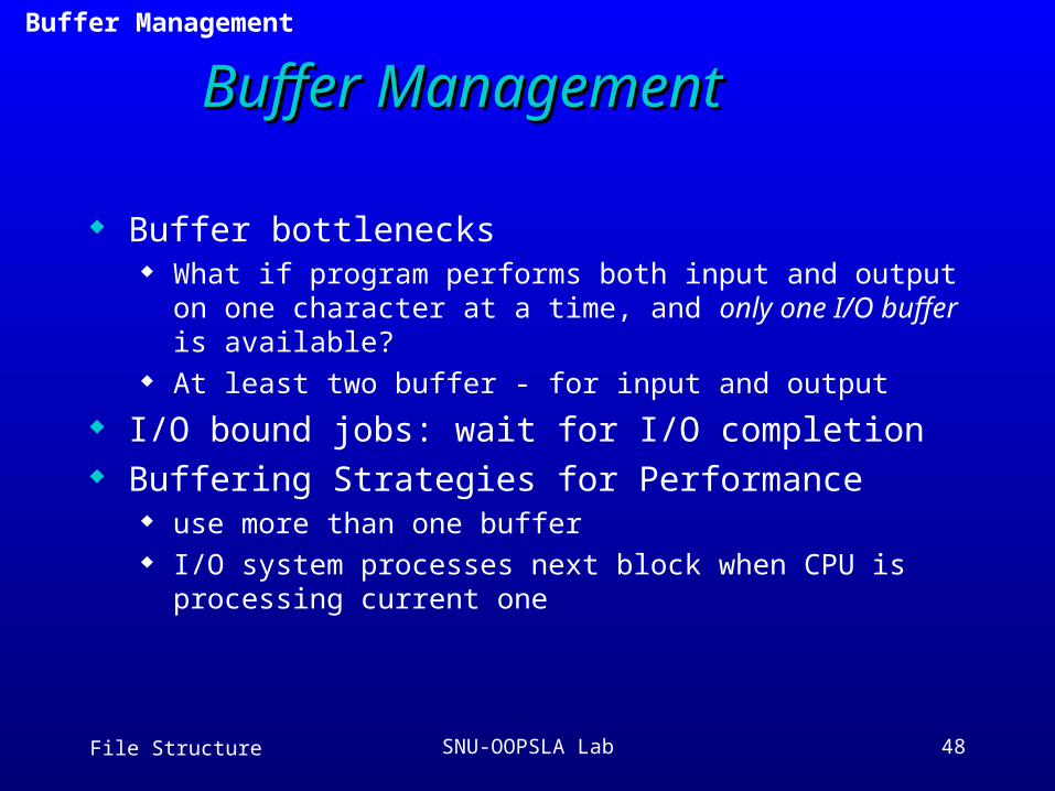
Buffer bottlenecks What if program performs both input and output on one
character at a time, and only one I/O buffer is available? At least two buffer - for input and output
I/O bound jobs: wait for I/O completion Buffering Strategies for Performance
use more than one buffer I/O system processes next block when CPU is processing
current one
3.9 Buffer Management
File Structure SNU-OOPSLA Lab 49
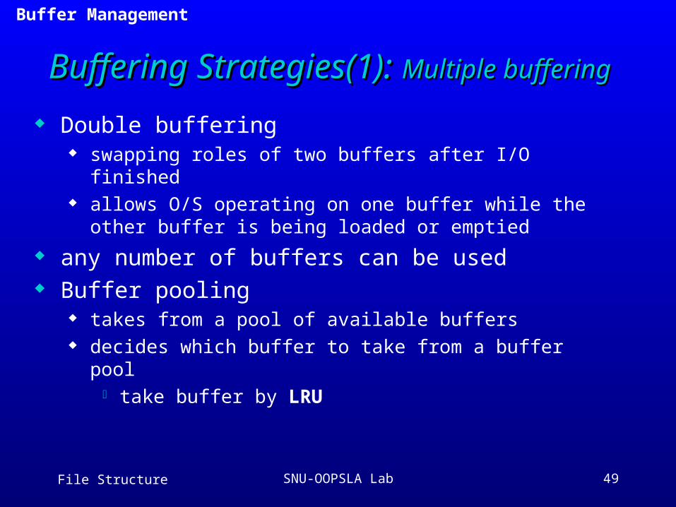
Buffering Strategies(1): Buffering Strategies(1): Multiple bufferingMultiple buffering
Double buffering swapping roles of two buffers after I/O finished allows O/S operating on one buffer while the other buffer is
being loaded or emptied
any number of buffers can be used Buffer pooling
takes from a pool of available buffers decides which buffer to take from a buffer pool
take buffer by LRU
3.9 Buffer Management
File Structure SNU-OOPSLA Lab 50
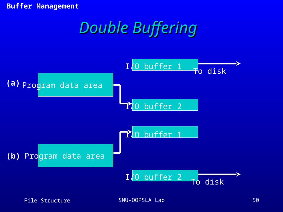
Double BufferingDouble Buffering
Program data area
Program data area
To disk
To diskI/O buffer 1
I/O buffer 1
I/O buffer 2
I/O buffer 2
(a)
(b)
3.9 Buffer Management
File Structure SNU-OOPSLA Lab 51
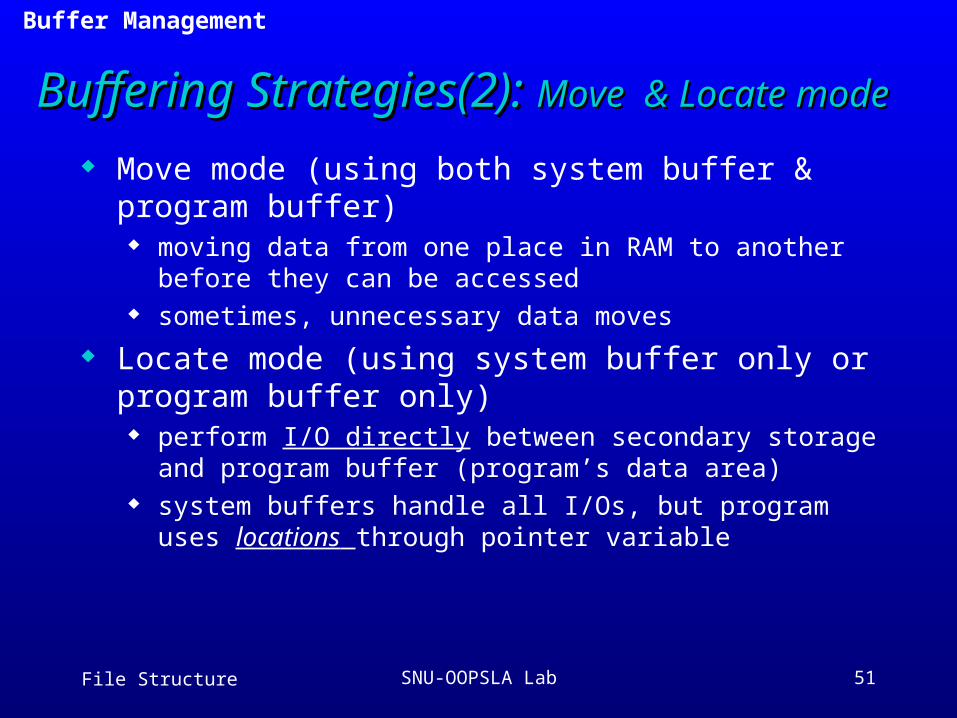
Buffering Strategies(2): Buffering Strategies(2): Move & Locate modeMove & Locate mode
Move mode (using both system buffer & program buffer) moving data from one place in RAM to another before they
can be accessed sometimes, unnecessary data moves
Locate mode (using system buffer only or program buffer only) perform I/O directly between secondary storage and program
buffer (program’s data area) system buffers handle all I/Os, but program uses locations
through pointer variable
3.9 Buffer Management
File Structure SNU-OOPSLA Lab 52
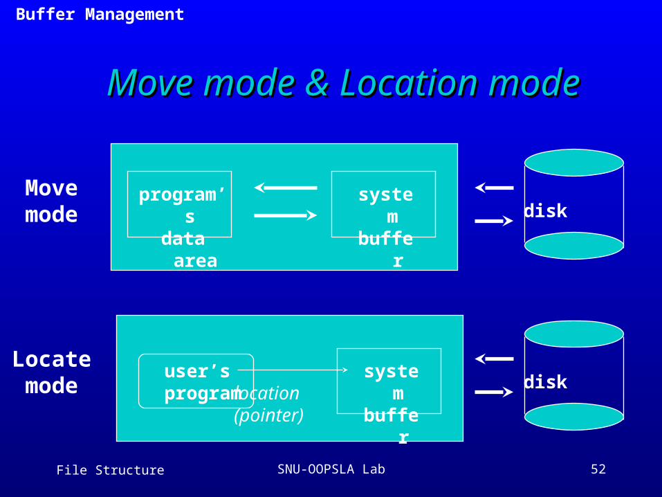
Move mode & Location modeMove mode & Location mode
system buffer
program’s data area
system buffer
disk
diskuser’s
programlocation(pointer)
Movemode
Locatemode
3.9 Buffer Management

File Structure SNU-OOPSLA Lab 53
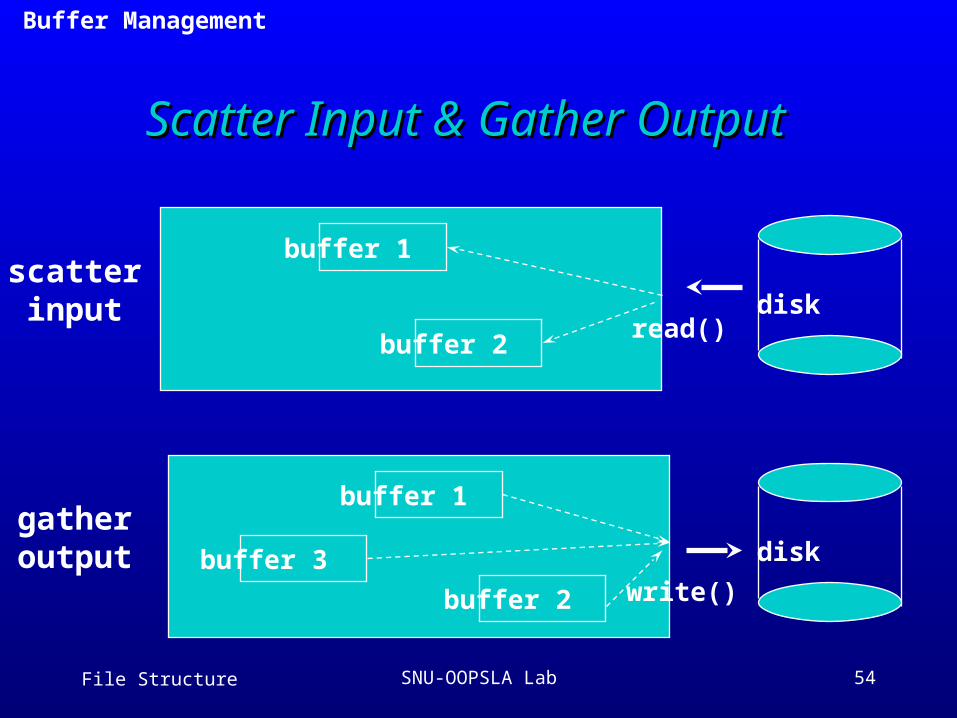
Buffering Strategies(3): Buffering Strategies(3): Scatter/Gather IOScatter/Gather IO
A file with many blocks and each block with header and data
Need to put the headers in one buffer and the data in a different buffer ==> may occur complication
Scatter-input mode a single READ can scatter data into a collection of buffers
Gather-output mode a single WRITE can gather several buffers and output
3.9 Buffer Management
File Structure SNU-OOPSLA Lab 54
Scatter Input & Gather OutputScatter Input & Gather Output
disk
disk
scatterinput
gatheroutput
read()
write()
buffer 1
buffer 2
buffer 1
buffer 3
buffer 2
3.9 Buffer Management
File Structure SNU-OOPSLA Lab 55
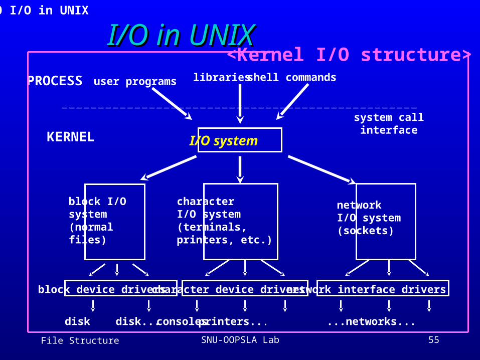
I/O in UNIXI/O in UNIX<Kernel I/O structure>
3.10 I/O in UNIX
I/O system
PROCESS
KERNEL
user programs libraries shell commands
system callinterface
block I/Osystem(normal files)
characterI/O system(terminals,printers, etc.)
networkI/O system(sockets)
block device drivers
disk disk...
character device drivers
consoles printers...
network interface drivers
...networks...
File Structure SNU-OOPSLA Lab 56
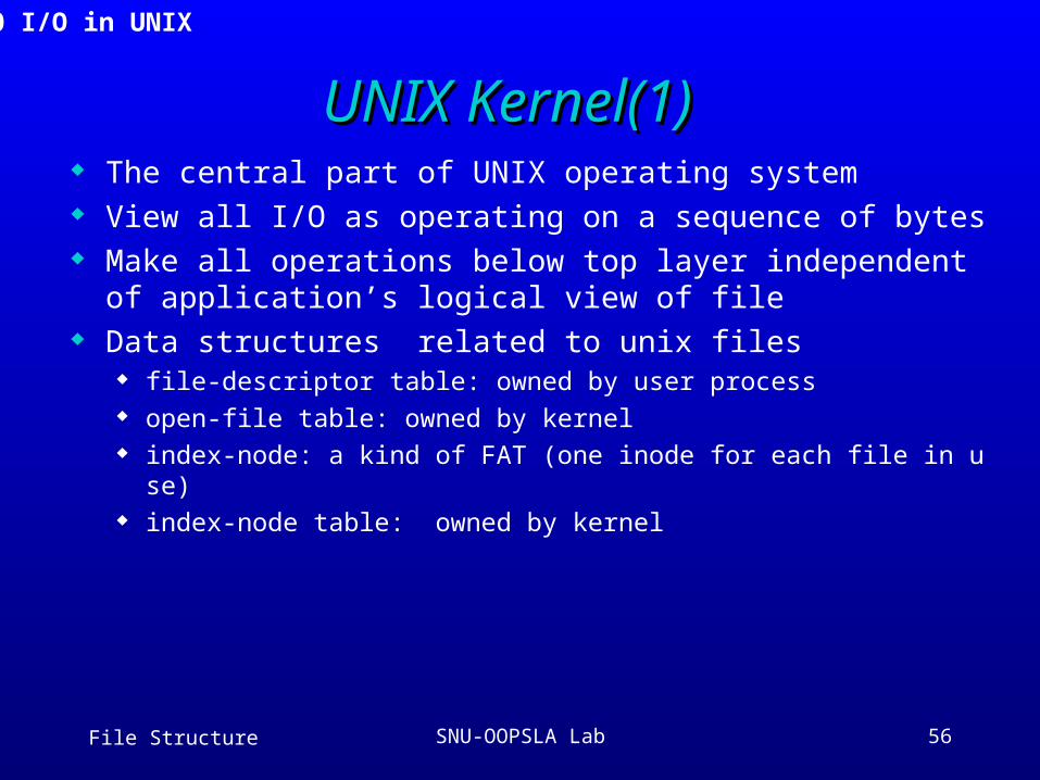
UNIX Kernel(1)UNIX Kernel(1) The central part of UNIX operating system View all I/O as operating on a sequence of bytes Make all operations below top layer independent of applic
ation’s logical view of file Data structures related to unix files
file-descriptor table: owned by user process open-file table: owned by kernel index-node: a kind of FAT (one inode for each file in use) index-node table: owned by kernel
3.10 I/O in UNIX
File Structure SNU-OOPSLA Lab 57
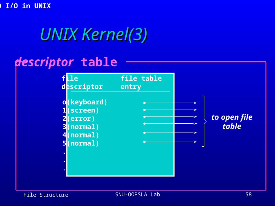
UNIX Kernel(2)UNIX Kernel(2)
File descriptor table associates each file descriptor to open file table every process has its own file descriptor table
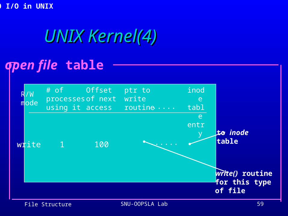
Open file table entries for every open file file structures: r/w mode, offset, reference count
3.10 I/O in UNIX
File Structure SNU-OOPSLA Lab 58
UNIX Kernel(3)UNIX Kernel(3)
file descriptor
file tableentry
o(keyboard)1(screen)2(error)3(normal)4(normal)5(normal)...
to open filetable
descriptor table
3.10 I/O in UNIX
File Structure SNU-OOPSLA Lab 59
UNIX Kernel(4)UNIX Kernel(4)
R/Wmode
# ofprocessesusing it
Offsetof nextaccess
ptr towriteroutine
inodetableentry......
write 1 100 ......to inode table
write() routinefor this typeof file
open file table
3.10 I/O in UNIX
File Structure SNU-OOPSLA Lab 60
UNIX Kernel(5)UNIX Kernel(5)
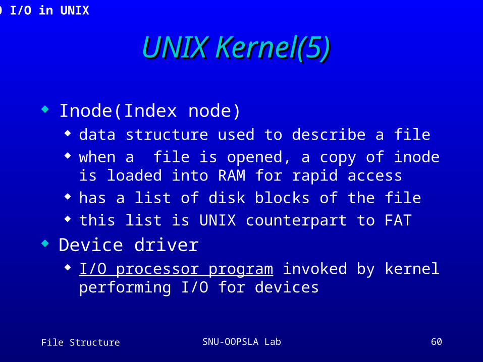
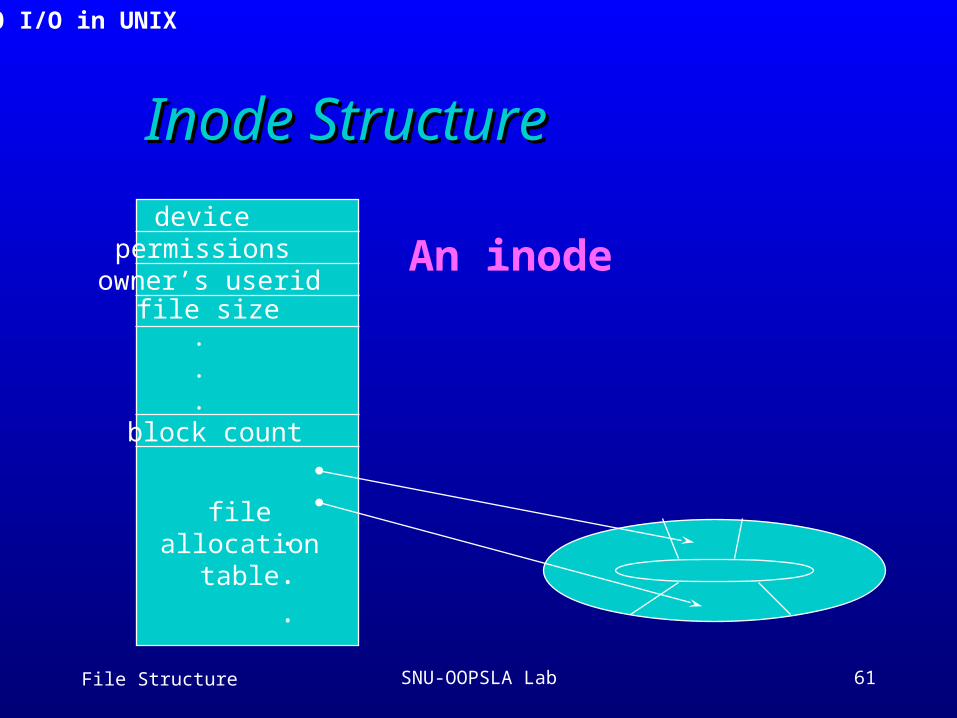
Inode(Index node) data structure used to describe a file when a file is opened, a copy of inode is loaded
into RAM for rapid access has a list of disk blocks of the file this list is UNIX counterpart to FAT
Device driver I/O processor program invoked by kernel
performing I/O for devices
3.10 I/O in UNIX
File Structure SNU-OOPSLA Lab 61
Inode StructureInode Structure
devicepermissions
owner’s useridfile size
block count
fileallocation
table
.
.
.
.
.
.
An inode
3.10 I/O in UNIX
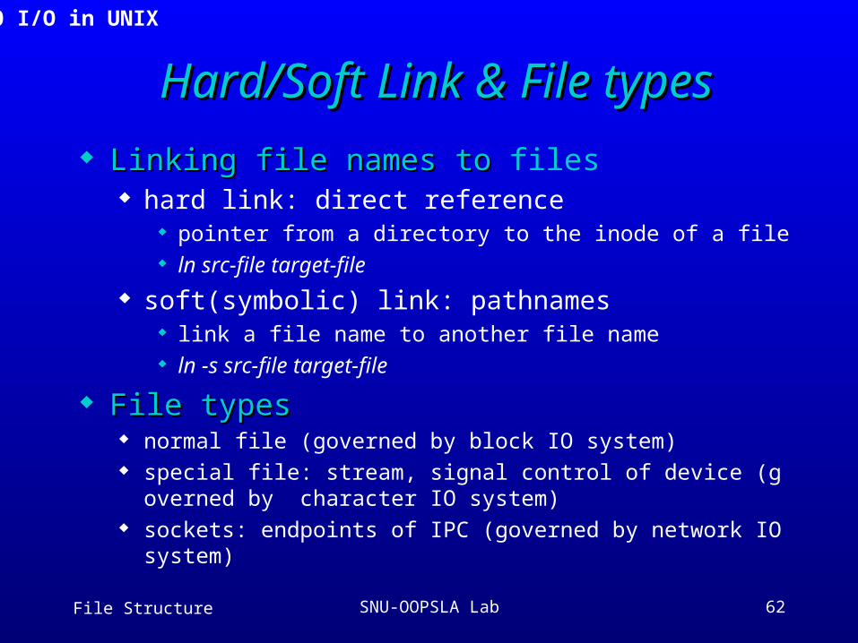
File Structure SNU-OOPSLA Lab 62
Hard/Soft Link & File typesHard/Soft Link & File types
Linking file names to Linking file names to files hard link: direct reference
pointer from a directory to the inode of a file ln src-file target-file
soft(symbolic) link: pathnames link a file name to another file name ln -s src-file target-file
File typesFile types normal file (governed by block IO system) special file: stream, signal control of device (governed by ch
aracter IO system) sockets: endpoints of IPC (governed by network IO system)
3.10 I/O in UNIX

File Structure SNU-OOPSLA Lab 63
Let’s Review !!!Let’s Review !!!3.1 Disks
3.2 Magnetic Tape
3.3 Disk versus Tape
3.4 Introduction to CD-ROM
3.5 Physical Organization of CD-ROM
3.6 CD-ROM Strengths and Weaknesses
3.7 Storage as a Hierarchy
3.8 A Journey of a Byte
3.9 Buffer Management
3.10 I/O in UNIX