figure 27.16 natural-draught concrete cooling tower ...nguyen.hong.hai.free.fr/ebooks/science and...
TRANSCRIPT

changes of diameter not exceeding 5% can be acceptedwithout harm to the pipe.
(4) Laid underground with complete or partial concrete sur-round if the external loading exceeds that which can becarried by the pipe with earth support only.
If steel culverts were designed only to withstand internal pres-sures, the plate would probably be too thin to withstand thehandling stresses during installation. There are therefore mini-mum practical thicknesses of plate from which pipes are made,these being 12 mm plate for pipes from 1.6 to 2.5 m in diameter,then thickening by 2 mm for each 0.5 m increase of diameter to22 mm plate for 5 m diameter pipe. Such pipes are more thanstrong enough for internal pressures in cw culverts, but fordiameters exceeding 1.6 m they are not suitable to resist vacuumconditions.
For steel pipe culverts subject to vacuum conditions, laidabove ground without concrete surround, the plate thicknesscan be calculated from the formula for buckling:
- 2E (*\P~T^ \d)
where p is the external collapse pressure (taken as 2 atmospheresto include a factor of safety of 2 to allow for manufacturingtolerances = 0.2 N/mm2), E is the modulus of elasticity (taken as200 000 N/mm2), p is Poisson's ratio (taken as 0.3) and t/d is theratio of plate thickness to pipe diameter.
From this, t should be not less than <//130, giving plate thick-nesses varying from 16 mm for 2 m diameter pipe to 40 mm for5 m diameter pipe. This takes into account only the externalload due to vacuum conditions and applies only to steel pipeslaid above ground without concrete surround. External loadingand ground support must be considered where steel pipessubject to vacuum conditions are laid below ground.
27.6.2.7 Water velocities and mussel growth
Velocities are kept above the self-cleansing velocity of 0.8 m/s.The minimum velocity for sea water in once-through systems isconsidered to be 3.25 m/s, since below this velocity mussels cansettle on the culvert walls and floor. When established, musselgrowth can form a thick rough lining on the walls and floors ofthe inlet culverts, so restricting water flow. Mussels may alsobecome detached and can cause damage if the shells are carriedto the condenser to become lodged in the water tubes. However,it is impossible to maintain a velocity above 3.25 m/s at all timesand provision is made to inject chlorine into the incomingcooling water during the spatting season to kill mussels or spat.A similar method is used to reduce algae growth on tower-cooled stations.
27.7 Natural-draught cooling towers
by K P Grubb, BSc(EnQ), MICE
A natural-draught cooling tower consists essentially of a largereinforced concrete chimney or shell into which air is admittedaround the base in such a manner that the induced flow of airintimately mixes with and cools a falling stream of water whichhas been heated in passing through the turbine condensers. Thiswater is normally distributed uniformly across the area of theshell by a sprinkler system, supported at about 14m aboveground level.
Figure 27.16 Natural-draught concrete cooling tower. (Courtesy:Central Electricity Generating Board)
The engineering design of a cooling tower thus presents acombination of hydraulic, aerodynamic, thermodynamic andstructural problems. Only the last will be considered here.
The structure supporting the packing, distribution system andeliminator will generally be formed of precast concrete unitsdesigned in accordance with BS CP 110.
Two variations from this Code lie in the use of reduced coverto reinforcement in order to minimize the sectional size of theprecast members and their impedance to cooling air, and inspecifying tighter dimensional tolerances to avoid unacceptablecumulative errors during the erection of the large number ofprecast elements used in the pack support structure.
Immediately below the sprinkler system a packing is situated,the main function of which is to increase the specific surface ofthe water stream so that maximum heat transfer takes place.
Currently, it takes the form of either: (1) splash packing,consisting generally of timber or plastic laths to transform thewater stream into droplet form; or (2) film packing, consistingeither of flat or corrugated asbestos cement sheets set on edge orof prefabricated plastic modules, both types creating a film ofwater on the sheeting surfaces such that maximum contact withthe cooling air stream is created (Figure 27.16). The cooledwater is finally collected in a concrete pond, which covers thebase area of the tower, for recirculation to the condensers. Twocooling towers about 90m in diameter and 115m high arerequired to cool the water flowing through the condensers of a500 MW unit.
Waterdistributionpipes
Sprayeliminator
Asbestos cementsheet pack
Spraynozzles

27.7.1 The tower shell
Hyperboloidal or near hyperboloidal shells have been used forcooling towers since 1918, when the shape was adopted toprovide stability against the gross foundation settlement whichwas anticipated by van Itersen in his design for the Dutch StateMines. For equivalent strength and stability this shape has asubstantial advantage in economy of both material and surfacearea over any equivalent cylindrical structure. When the furtheraesthetic advantage of the conic section is added, it is notsurprising that the shape has remained virtually unchallengedsince that date. It is now a shape uniquely associated withcooling towers.
The design of the shell presents the only unconventionalstructural design features in a cooling tower. In the UK, theonly significant loading on a tower shell is that due to wind andin consequence the structure is very light when compared withother structural shells. As the wall thickness is much smallerthan the other principal dimensions, the structure tends to resistwind loading predominantly by membrane and tangential shearstress resultants rather than by bending resistance.
However, the validity of the membrane theory as a basis ofdesign has been questioned since the mid 1970s when finiteelement methods became generally available resulting in fullbending analyses becoming more common. It is likely that acomparison of the two methods will not show significant designchanges but the finite element methods can be of great value inmore accurately modelling the geometry of the shell, ring beam,columns and foundations. Foundation settlement is one parti-cular aspect that can be incorporated into a finite elementanalysis. Such an analysis will reveal the nonsymmetrical hori-zontal bending effects which the shell, if considered as amembrane, is not intrinsically well prepared to resist. Outsidethe UK there exists the possibility of seismic loadings being inexcess of wind loadings. Where national codes require a nonli-near analysis of tower structures to be carried out in thesecircumstances, e.g. for nuclear installations, then again a finiteelement method is essential.
Several other aspects of shell design deserve mentioning.Under high-wind conditions the possibility of elastic instabilityexists. Although research work has indicated, that this form offailure is significantly less probable than the overstressing modein conventionally sized and designed shells, the presence ofmeridional cracking can cause a dramatic decrease in thebuckling resistance of a hyperboloid. However, as towers in-crease in height and horizontal dimensions the need to estimatethe buckling capacity of such towers becomes more importantand requires that a geometrically nonlinear analysis should becarried out as part of the design process.7
Cracking in the shell surface can also result from operationalthermal and moisture movement transients. These may well beintensified by ambient temperature variations. The effect of suchcracking alone is only structurally significant in its consequen-tial effect of rendering the shell more susceptible to buckling orvibrational failure although long-term corrosion of the shellreinforcement must also be taken into consideration. Hence, anestimation of temperature stresses in the tower shell should bemade.7
Large constructional inaccuracies in the shape of hyperbolicshells can seriously reduce'their resistance to wind loading.Hence precise control of shape is of great importance duringconstruction.
27.7.2 Wind loading
The current British Standard8 for the structural design ofcooling tower shells requires that wind loading shall be assessedin accordance with BS CP 3: Chapter V, Part 2. The towerwould therefore be regarded as a class C structure and would be
designed to withstand the effects of a 15s gust calculated at thecornice level and applied as a nonvariable quasi-static loadingover the tower height.
A current draft amendment to BS CP 3, Chapter V, Part 2suggests that this Code does not apply to buildings, or struc-tures, with properties such as low natural frequency or lowdamping which make them susceptible to dynamic response. Itgoes on to say that the assessment of such response should bebased upon published sources or experimental results such asproperly conducted wind tunnel tests.
Wind tunnel testing of towers in groups carried out in the UKand abroad in the last decade have revealed that loadings in atower caused by that portion of a wind spectrum at or near thenatural frequency of the tower, i.e. due to the dynamic response,are of more significance than hitherto suspected. Hence, someallowance for resonance loadings should be made in assessingstress resultants in the shell although currently the range oftower sizes and of tower grouping to be considered only allowsempirical expressions to be adopted.79
The distribution of pressure over the shell surface in anyhorizontal plane was measured at the time of the Ferrybridgeinvestigation from wind tunnel tests and the results of those testsform the basis for the pressure coefficient distribution specifiedin the British Standard.8
27.7.3 Support columns and foundations
The design of foundations and diagonal support columns fortower shells is largely conventional, but any possibility ofinducing uplift conditions on the upstream side of larger towersrequires most careful consideration, in particular where thelifting of foundations under seismic loading might be used as adesign aid for alleviating the uplift stresses in the shell andsupport columns.
Circumferential continuity of the foundations and/or pondwall is recommended in preference to discrete pad foundationsbelow each support column node.
The transfer of load and horizontal shear from the shell intothe support columns is effected through a thickening of thelower shell section, or ring beam. Very high maximum columnloads, which may result from elastic analysis of the supportcomplex, are likely to be modified or smoothed out by redistri-bution in practice, since it is clear that the loads are transient bynature and that the least degree of nonlinearity induced in the
R a k i n g column500 mm square
G r o u n d l eve l
Pond baseR a k i n g piles450 mm dia. /
Figure 27.17 Cooling-tower foundation
columns by momentary overstress will permit such a redistribu-tion. Some allowance for this effect is normally permitted indesign.
Figure 27.17 shows a cross-section through a piled founda-tion for a cooling tower. The concrete ring beam (supported onraking piles) carries a triangulated system of raking supportcolumns, which in turn support the ring beam created by thethickening of the lower section of the tower shell. The water inthe pond and the tower packing are carried by the base slab.
In this design the pond wall forms an integral part of the pilecap. It can equally form part of a composite contact foundation.Some economies may be achieved by supporting the rakingcolumns directly on the pile cap or contact foundation. In suchcases the pond wall may be constructed outside the columns asthe last item, hence providing easier access to the pond duringthe construction period.
27.8 Chimneys
by K P Grubb, BSc(EnQ), MICE
The function of a chimney is to discharge flue gases to theatmosphere at such a height and velocity that the concentrationof pollutants such as sulphur dioxide is kept within acceptablelimits at ground level. Brickwork makes a suitable structure forfree-standing chimneys up to about 60m high but for tallerchimneys the overturning moment due to increased wind loadcan be more economically resisted by a reinforced concreteshaft.
Fossil-fired stations will generally be equipped with eithercoal- or oil-fired boilers. Some coals have very high sulphurcontent, but generally the sulphur content of most British coal isreasonably low. With liquid fuels the sulphur content is morevaried and depends in the main on the origin and subsequentprocessing. Hence, the flue gases from a large oil-fired boilermight have a sulphur content of up to 3% and a back-endtemperature of about 15O0C. At or near to dewpoint a dilutecondensate of sulphuric acid might be produced on the fluesurface if temperature conditions are favourable.
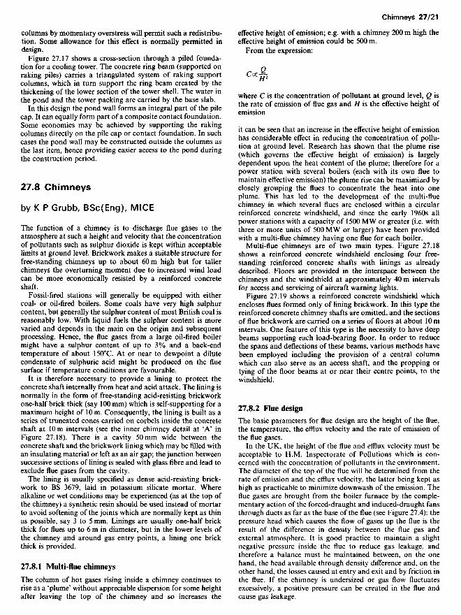
It is therefore necessary to provide a lining to protect theconcrete shaft internally from heat and acid attack. The lining isnormally in the form of free-standing acid-resisting brickworkone-half brick thick (say 100 mm) which is self-supporting for amaximum height of 10 m. Consequently, the lining is built as aseries of truncated cones carried on corbels inside the concreteshaft at 10m intervals (see the inner chimney detail at 'A' inFigure 27.18). There is a cavity 50mm wide between theconcrete shaft and the brickwork lining which may be filled withan insulating material or left as an air gap; the junction betweensuccessive sections of lining is sealed with glass fibre and lead toexclude flue gases from the cavity.
The lining is usually specified as dense acid-resisting brick-work to BS 3679, laid in potassium silicate mortar. Wherealkaline or wet conditions may be experienced (as at the top ofthe chimney) a synthetic resin should be used instead of mortarto avoid softening of the joints which are normally kept as thinas possible, say 3 to 5 mm. Linings are usually one-half brickthick for flues up to 6 m in diameter, but in the lower levels ofthe chimney and around gas entry points, a lining one brickthick is provided.
27.8.1 Multi-flue chimneys
The column of hot gases rising inside a chimney continues torise as a 'plume' without appreciable dispersion for some heightafter leaving the top of the chimney and so increases the
effective height of emission; e.g. with a chimney 200 m high theeffective height of emission could be 500 m.
From the expression:
Coc2C<X№
where C is the concentration of pollutant at ground level, Q isthe rate of emission of flue gas and H is the effective height ofemission
it can be seen that an increase in the effective height of emissionhas considerable effect in reducing the concentration of pollu-tion at ground level. Research has shown that the plume rise(which governs the effective height of emission) is largelydependent upon the heat content of the plume; therefore for apower station with several boilers (each with its own flue tomaintain effective emission) the plume rise can be maximized byclosely grouping the flues to concentrate the heat into oneplume. This has led to the development of the multi-fluechimney in which several flues are enclosed within a circularreinforced concrete windshield, and since the early 1960s allpower stations with a capacity of 1500 MW or greater (i.e. withthree or more units of 500 MW or larger) have been providedwith a multi-flue chimney having one flue for each boiler.
Multi-flue chimneys are of two main types. Figure 27.18shows a reinforced concrete windshield enclosing four free-standing reinforced concrete shafts with linings as alreadydescribed. Floors are provided in the interspace between thechimneys and the windshield at approximately 40m intervalsfor access and servicing of aircraft warning lights.
Figure 27.19 shows a reinforced concrete windshield whichencloses flues formed only of lining brickwork. In this type thereinforced concrete chimney shafts are omitted, and the sectionsof flue brickwork are carried on a series of floors at about 10mintervals. One feature of this type is the necessity to have deepbeams supporting each load-bearing floor. In order to reducethe spans and deflections of these beams, various methods havebeen employed including the provision of a central columnwhich can also serve as an access shaft, and the propping ortying of the floor beams at or near their centre points, to thewindshield.
27.8.2 Flue design
The basic parameters for flue design are the height of the flue,the temperature, the efflux velocity and the rate of emission ofthe flue gases.
In the UK, the height of the flue and efflux velocity must beacceptable to H.M. Inspectorate of Pollutions which is con-cerned with the concentration of pollutants in the environment.The diameter of the top of the flue will be determined from therate of emission and the efflux velocity, the latter being kept ashigh as practicable to minimize downwash of the emission. Theflue gases are brought from the boiler furnace by the comple-mentary action of the forced-draught and induced-draught fansthrough ducts as far as the base of the flue (see Figure 27.4): thepressure head which causes the flow of gases up the flue is theresult of the difference in density between the flue gas andexternal atmosphere. It is good practice to maintain a slightnegative pressure inside the flue to reduce gas leakage, andtherefore a balance must be maintained between, on the onehand, the head available through density difference and, on theother hand, the losses caused at entry and exit and by friction inthe flue. If the chimney is undersized or gas flow fluctuatesexcessively, a positive pressure can be created in the flue andcause gas leakage.

Figure 27.18 18 200 m multi-flue chimney with free-standingflues
Typical cross section
6m dia.flue
Vent
Detail 'A'
100mm acid resislirvc}-brickwork liningcarried on shaftcorbels
Glasswoolpacking
Access floors at40m intervals
50 mminsulation
Concrete shaft
/WindshieldLeadseal

Glass wooland lead seal
Flue-supportingfloors at 10mintervals
100mmacid-resistingbrickwork liningcarried on floors
Detail A
Windshield
Typical cross section
6 md ia . f lue
Accessshaft
Vent
Figure 27.19 200 m multi-flue chimney with flues supported onwindshield
Cros
s be
am
Details at flue entry vary; where entry is from beneath it isusual to provide a 'lobster-back' bend of steel plate in order toreduce friction and turbulence, in which case the flue liningcommences at about 25 m above the chimney base. In the caseof side entry it is usual to provide 'splitters' (i.e. deflector plates)over the area of entry to reduce turbulence in the gases due tothe right angle change in direction.
The multi-flue chimney of a 2000 MW station would be about200 m high with flues about 6 m in diameter and efflux velocityabout 23 m/s; for a 4000 MW station the chimney would beabout 260 m high and the efflux velocity about 26 m/s.
In the near future main boiler plant will be fitted with flue gasdesulphurization equipment to reduce the toxicity of chimneyemissions. This will affect chimney lining design and perform-ance significantly, and it will be some time before these reviseddesigns are proven.
27.8.3 Windshield design
The shafts of single-flue chimneys and the windshields of multi-flue chimneys must be designed to withstand the loadings fromwind, self weight and temperature. Code of Practice 3, ChapterV, Part 2 requires that any structure whose greatest lateral orvertical dimension exceeds 50 m shall be designed to withstand a15s gust wind speed. However, the Code recognizes the limi-tations of applying quasi-static loadings to buildings or struc-tures which are susceptible to dynamic response.
The basic design of the shaft or windshield as a cantileverresisting overturning moment under normal wind forces shouldtake due account of buffeting in the natural wind and it isdesirable to apply a factor to these forces which will adequatelyallow for dynamic downwind effects. Two such methods areproposed in current publications.1011
Generally, this basic design will be carried out on the basis ofan elastic analysis but model codes11 normally require in addi-tion consideration of an extreme wind condition with higherallowable stresses. Where a building or structure is susceptibleto excitation by vortex shedding or other aerodynamic instabi-lity the maximum dynamic response may occur at wind veloci-ties lower than normal wind force. It is therefore important todetermine the conditions under which such responses couldoccur.10"12
It is necessary (particularly for a windshield enclosing free-standing shafts) to investigate the ovalling stresses caused by thevarying pressure distribution around the windshield whichresult in positive and negative bending moments in the hori-zontal plane. Generally, the estimation of vertical and hori-zontal stress resultants are considered separately but withwindshields having a ratio of mean diameter: shell thickness inexcess of 50 it may be desirable to carry out a full bending andmembrane analysis of the windshield as a thin shell.
Temperature stresses are calculated on the basis of thetemperature differential which exists across the shaft or wind-shield walls and which causes tensile strain on the cooler face.10"
In designing the floors inside the windshield their effect asstiffening diaphragms should be considered, otherwise the wind-shield could be of uneconomic thickness. The floor design mustalso include open areas, generally covered with open-meshflooring, to allow sufficient upflow of air to cool the interspacein which the air temperature should not normally exceed 380C.
Although it is usual to provide an expansion gap between thefloors and any free-standing concrete shafts in a windshield, thefloors might be brought into contact with the shafts and loadtransferred laterally owing to horizontal deflection of the wind-shield. Hence, the shafts should be designed to withstand aproportion of the total wind load based on the relative stiffnessof shafts and windshield.
27.8.4 Protection of chimney top from acid attack
The top of a single- or multi-flue chimney for 10% of its heightshould be externally protected by acid-resisting paint or tiles.On multi-flue chimneys the flues projecting above the top floorare normally of acid-resisting brickwork only. Steel flues couldbe used, but they are expensive and difficult to erect. Glass-reinforced plastics are light and easy to erect but there isinsufficient operating experience to justify their general use atpresent. The top floor may be covered with quarry tiles.
27.8.5 Aircraft warning lights
Aircraft warning lights must be provided in accordance withRegulations, usually at 50 m intervals vertically and at the top ofthe chimney. Three lights at 120° intervals (or four at 90°intervals, for a multi-flue chimney with four flues) are providedat each level.
On multi-flue chimneys, the lights are usually fixed on theouter face of inward-opening doors in the windshield, accessibleat the appropriate floor level. On single-flue chimneys, lamps aremaintained by steeplejacks and fittings are duplicated.
27.8.6 AccessBronze sockets in which steeplejacks may insert ladder fixinghooks should be built in the external face of single-flue chim-neys; they are unnecessary on multi-flue chimneys because thereis internal access to the top.
27.8.7 Lightning protection
A lightning protection system is necessary. A coronal band isprovided and CP 326 permits the use of steel reinforcement in aconcrete structure as down conductors, provided that the rein-forcement cage is adequately earthed and tested on completionfor continuity.
27.8.8 Foundations
The varying subsoil conditions which may be experienced onpower station sites results in an equal variety of foundationtypes.
The total weight of a 200-m high multi-flue chimney for a2000 MW power station approaches 20 0001. Combined withthe resulting down-wind or cross-wind loadings the resultingmaximum bearing pressure would generally preclude the use ofcontact foundations, solid or annular, unless sound rock ispresent at an economic depth. Both piled foundations and thoseemploying cylinders or caissons have been provided on powerstations.
In all cases, the dynamic response of a chimney will varyinversely as the natural frequency of the combined windshield/foundation. Hence, in calculating this parameter due allowancemust be made for modelling the soil stiffness under the founda-tion.
27.9 Nuclear reactors and reactorbuildings
by N G Eggleton, BSc, FICE
In nuclear power stations, the turbo-generators are very similarto those in coal- or oil-burning stations, but instead of heatbeing produced from the combustion of coal or oil in thefurnace of a boiler, heat is produced by the nuclear fission of aradioactive material in a reactor. In the UK, except for the

Figure 27.20 Advanced Gas-cooled Reactor. (1) Reactor core;(2) supporting grid; (3) gas baffle (steel cylinder 14 m diameter,without bottom and with torispherical dome); (4) gas circulators;(5) boilers; (6) thermal insulation; (7) reheat steam penetrations;(8) main steam penetrations; (9) boiler feed penetrations; (10)prestressed concrete pressure vessel (19m diameter and 19.35 mhigh internally); (11) cable-stressing galleries; (12) charge-facelevel; (13) fuelling machine; (14) standpipes (one standpipe aboveevery channel in core for refuelling or control)
The first nuclear power station programme in the UK con-sisted of nine Magnox stations commissioned between 1962 and1968, and the second consists of seven Advanced Gas-cooledReactor (AGR) stations commissioned between 1972 and 1978.
The Magnox reactors use natural uranium fuel elements inmetal form, encased in magnesium alloy (magnox) finnedcontainers about 25 mm in diameter and 0.5 to I m long tosupport the fuel and contain the radioactive products of fission;they are graphite-moderated and are cooled by carbon dioxidegas. The metal fuel and magnox cans limit the coolant tempera-ture so that the steam temperatures and pressures reached in theboilers are suitable only for turbo-generators up to 300 MWcapacity. The fuel irradiation is 3000 to 4000 MW days pertonne.
The AGRs use enriched uranium (uranium dioxide) fuel. Thenatural uranium is enriched in a separation process by increas-ing the proportion of the radioactive isotope present. The fuelelements consist of 36 stainless-steel ribbed tubes containing14.5-mm diameter uranium dioxide pellets, the tube clusterbeing contained within a graphite sleeve 190mm in diameter.Eight such elements each 1 m long, are linked together by a tiebar to form a fuel stringer, and each channel in the reactor coreaccommodates one stringer. Oxide fuel and stainless-steel canspermit higher operating temperatures and the steam conditionsreached in the boilers (170kgf/cm2 and 54O0C) are suitable formodern designs of 660 MW turbo-generators. The fuel irradia-tion is about 18 000 MW days per tonne. The moderator in thecore remains graphite and the coolant remains carbon dioxidegas, but it is circulated at much higher pressure to increase itsheat-transfer capacity.
The gas operating pressure in the series of Magnox reactorsprogressed from about 1000kN/m2 to 2000 kN/m2 and theearlier reactors were contained in steel pressure vessels up to90 mm thick. As reactors of increasing size were designed andcoolant pressures increased, the fabrication of still larger andthicker steel vessels became impracticable, and prestressed con-crete pressure vessels were used in the later Magnox reactorsand in all the AGRs. The AGR pressure vessels operate at acoolant pressure of 4000-6000 kN/m2.
27.9.1 Reactor pressure vessel
The prestressed concrete pressure vessel shown in Figure 27.20is a vertical cylinder with helical multi-layer post-tensionedcables in the walls, so arranged that no cables are requiredacross the top and bottom slabs. The pattern of cables is shownin Figure 27.21. The bottom slab is designed for a workingpressure of 4200 kN/m2 a.b.s. which is the outlet pressure fromthe gas circulators. The top slab and walls, however, aredesigned for the lower pressure of 3900 kN/m2 following thecoolant pressure drop in the core. The vessel inner surfaces areinsulated and cooled to maintain concrete temperatures gener-ally below 7O0C.
The optimum angle of inclination of the helix is that for whichthe radial and vertical components of prestress are in the sameratio as the respective gas forces at ultimate load conditions.The prestressing cables are taken up into an annular extensionof the cylinder wall beyond the flat slabbed end to such a heightthat the radial component of load from the extended cablesprovides sufficient force to restrain the end slabs. This arrange-ment permits any number of penetrations in the top slabwithout reducing the load-carrying capacity of the slab.
The prestressing design has a high degree of redundancy andthe cable tensions are checked periodically; the pressure vessel istherefore very safe against rupture. The cables are not grouted-in and they can be removed individually for inspection, and, ifnecessary, replacement.
27.9.2 Reactor foundations
The main load to be carried by the reactor building foundationsis the pressure vessel containing the reactor core. Because of the
recent commitment to the pressurized water reactor at Sizewell'B', all the reactors which have been built for the public supplyindustry use a circulating gas coolant for the nuclear fuel andare classified as gas-cooled reactors.
The reactor core consists of nuclear fuel elements housed invertical channels formed in a graphite moderator which isassembled from accurately machined graphite blocks. Themoderator slows down the neutrons radiated from the nuclearfuel in order to enhance the frequency of neutron collision andfission in the mass of nuclear fuel. The reactor is designed tocontain sufficient mass of nuclear fuel to give a self-sustainingreaction. The reactor core is enclosed within a pressure vesselmade of either steel or prestressed concrete, and heat exchangers('boilers') are arranged around its circumference; the boilers arelocated outside steel pressure vessels, but are contained insideconcrete vessels or are contained in cavities within the wall ofconcrete vessels. The reactor shown in Figure 27.20 is containedin a prestressed concrete pressure vessel. The gas coolant iscirculated inside the pressure vessel; it flows up the channels inthe moderator which houses the fuel elements and there it gainsheat, then flows outwards from the core and down through theboilers, where it gives up heat to water and steam in the boiler-turbine steam circuit. It is then recirculated upwards throughthe core. In order to increase its capacity to carry heat, the gas iskept at high pressure.

Figure 27.21 Prestressing system of a pressure vessel
load distribution, reactors in the UK have usually been sup-ported by direct bearing on the subsoil at a depth of about 10 m,though in one instance where it was impracticable to spread theload sufficiently at a reasonable depth the reactor was carried onconcrete shafts 2.3m in diameter taken into rock about 40mbelow ground level.
A contact foundation for an AGR with a prestressed concretepressure vessel is shown in Figure 27.22. Here the total weight ofthe loaded vessel is transmitted to a rock stratum at a loading ofabout 1200kN/m2 through a mass concrete base 26m in dia-meter. Surrounding the circular base is a reinforced concreteretaining wall, and the beams which support the considerablylighter external portions of the reactor building span the areabetween the pressure vessel and the retaining wall. The retainingwall is an independent structure and is only connected to themass concrete base by a continuous rubber stop.
27.9.3 Layout of reactor building
The Magnox and AGR nuclear stations each have two reactors,with one or two turbo-generators to each reactor. As with oil- orcoal-burning stations, the layout has developed to an in-linearrangement of the units (reactor and turbo-generators),generally with transverse arrangement of the turbo-generators.
In addition to the pressure vessels and access facilities aroundthem, the reactor building has to accommodate the followingprincipal items.
(1) Services annexe, consisting of offices, stores, laboratoriesand changing rooms and ablutions for personnel.
(2) Fuelling machine, which traverses the charge face over thereactor core. Operated by remote control, it removes cansor stringers of irradiated fuel from the reactor core andinserts new fuel elements. Also located at the charge-facelevel are workshops for maintenance of the fuellingmachine and other reactor equipment and the decontami-nation centre.
(3) Shielded block, which contains the new and irradiated fuel-handling equipment.
(4) Active waste disposal. After removal from an AGR core,the fuel element stringers are separated and certain compo-nents of the assembly are waste. This scrap has becomeradioactive whilst in the reactor core, and is disposed of byburial in deep vaults in the reactor building.
(5) Cooling pond in which irradiated fuel elements are storedfor about 3 months after removal from the reactor core.This allows the radioactivity to decay to a level at whichthey can be transported away from the power station forprocessing. There is some 6 m depth of water in the coolingpond to shield operatives from radiation.
(6) Cooling-pond water and active-effluent treatment plant(7) Carbon dioxide treatment plant(8) Ventilation plant. Most of the reactor building is artifici-
ally ventilated, because the size of the reactor buildingleaves many working areas with insufficient natural venti-lation and also because many areas must be kept undereither forced or plenum ventilation conditions to preventthe possibility of spread of radioactive contamination.
Elevation on 'AA*Developed elevation of vessel
Reheat steampenetrations
Main steampenetrations
FeedpenetrationsGas circulatorpenetrations
Stressing gallery
19m diameter
Figure 27.22 Reactor foundation. (Courtesy: Central ElectricityGenerating Board)
Stringent precautions are taken in the design and construc-tion of reactor foundations to ensure that long-term overallsettlement and differential settlement (both between buildingsand that which results in tilt of the reactor) will be withinacceptable limits.
Reactor
Cylindricalpressure vessel inprestressed concrete
Mass'concrete base26m dia. Stressing
galleryStressinggallery
Reinforcedconcreteretainingwall
Extracted air is also filtered before discharge to outsideatmosphere. The ventilation occupies a substantial part ofthe reactor building.
(9) Station control room, which contains the instrumentationand control panels for the operation of the reactors,boilers, turbo-generators, and ancillary plant.
(10) Electrical switchgear(11) Emergency generators. These are standby generators to
safeguard against failure of the station supply and of theincoming supply from the public system.
The main difference between the layouts of various reactorbuildings is in the location of the foregoing items, particularly ofthe services annexe. If the reactor spacing is kept to theminimum, the services annexe has to be located between thereactors and the turbo-generators, which results in long high-pressure pipework between boilers and turbines. By increasingthe spacing of the reactors and locating the services annexebetween them, the turbo-generators can be brought close to thereactors and the length of pipework reduced; this results in anincrease in building volume and costs, but is more than offset bythe saving on pipework.
27.10 Hydro-electric power andpumped storage
by D L McKie, CEng/ MICE
27.10.1 Hydro-electric power
In hydro-electric power plants, turbines are powered by passingthe greater part of the water flow of a river through the turbines.The plants fall into two categories according to the absence oruse of storage:
(1) Run-of-river plants, which have insignificant reservoir capa-city. At any particular time the power available for genera-tion is limited according to the river flow at that time, andthere is no reserve to meet high demand for electricity. Theseplants usually provide continuous generation (base loadsupply) and their output: capacity ratio (load factor) is high.
(2) Storage plants, which have a significant reservoir capacitysufficient to enable the water flow through the turbines to beregulated according to the demand for electricity. The loadfactor of these plants is usually low.
Thus, a run-of-river scheme will have a low dam (or weir) toraise the river level up to the intake works which give controlledconditions for flow of water to the pressure pipes or tunnelsleading to the turbines. A storage scheme will have a high damlocated in the best position, taking into account the volumeimpounded, elevation and construction cost. The intake worksof a storage scheme are normally incorporated in the dam, orbuilt as a tower either on the face of the dam, or free-standing inthe reservoir.
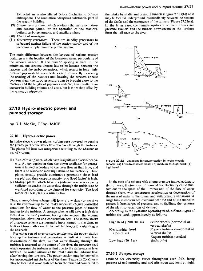
For either run-of-river or storage schemes, the power stationhousing the turbines and generators is built at a lower leveldownstream of the dam, so that water flowing through theturbines is returned to the course of the river; the pressure headwhich operates the turbines is that due to the difference in levelbetween the water surface at the intake and the tail-race levelafter leaving the turbines. The power station may be located at(or incorporated in) the base of the dam (Figure 27.23(a)) or itmay be located at some distance from the dam and connected to
Figure 27.23 Locations for power station in hydro-electricscheme, (a) Low-to-medium head; (b) medium-to-high head; (c)high head
In the case of a scheme with a long pressure tunnel leading tothe turbines, fluctuations of demand for electricity cause fluc-tuations in the speed of the turbines and of the flow of waterthrough them, with consequent acceleration or deceleration ofthe mass of water in the tunnel and with pressure variations. Asurge tank is constructed over and near the end of the tunnel toprotect it from surges of pressure, and to facilitate the responseof the plant to variations of demand.
According to the hydraulic operating head, different types ofturbine are used, approximately as follows:
High head (1500-300 m) Pelton wheels (horizontal orvertical shafts)
Medium/high head Francis turbines (horizontal or(550-30 m) vertical shafts)
Kaplan turbines (verticalLow head (50-5 m) shafts only)
27.10.2 Pumped storage
Demand for electricity varies throughout each 24 h, beinggreatest at mid morning and mid afternoon and least at night.
the intake by shafts and pressure tunnels (Figure 27.23(b)) or itmay be located underground intermediately between the bottomof the shafts and the emergence of the tunnels (Figure 27.23(c)).In the latter case, the tunnels upstream of the turbines arepressure tunnels and the tunnels downstream of the turbinesform the tail-race to the river.
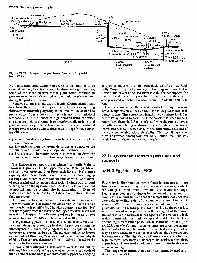
Figure 27.24 Pumped storage scheme, Dinorwic, Gwynedd,North Wales
Normally, generating capacity in excess of demand has to beclosed down but, if electricity could be stored in large quantities,some of the more efficient steam plant could continue togenerate at night and the stored output could be released laterduring the peaks of demand.
Pumped storage is an adjunct to highly efficient steam plantsto achieve the effect of storing electricity. It operates by usingtheir surplus generating capacity at the time of low demand topump water from a low-level reservoir up to a high-levelreservoir, and then at times of high demand using the waterstored in the high-level reservoir to drive hydraulic turbines andgenerate electricity. The scheme is built as a conventionalstorage-type of hydro-electric installation, except for the follow-ing differences:
(1) Water after discharge from the turbines is stored in a low-level reservoir.
(2) The turbines must be reversible to act as pumps, or thepumps and turbines may be separate machines.
(3) The electrical alternators operate as motors to drive thepumps, or as generators when being driven by the turbines.
The Dinorwig pumped storage scheme21 in North Wales isshown in Figure 27.24. The upper reservoir, Marchlyn Mawr,and the lower reservoir, Llyn Peris, each have a 'live' storagecapacity of 7 x 10⁶ m3. Both reservoirs were formed by enlargingexisting lakes. Marchlyn dam was constructed with 1.85 x 10⁶ m3
of zone graded and compacted slate rock fill which was surfacedwith asphalt on the upstream face. The lower lake was restoredto approximately its original size by excavating 4x 10⁶m3 ofwaste which had been tipped into it during more than 150 yr ofslate quarrying.
A maximum head of 542m is available to drive the six300 MW machines. Generation via all six vertical shaft Francispump-turbines is possible for 5 h, whilst pumping the full 'live'storage capacity from the lower to the upper reservoir takes justover 6 h. A feature of the Dinorwig scheme is that an outputfrom no load to 1320 MV can be achieved in 10s.
The generating plant is housed in a series of caverns exca-vated in slate and is located at a level which provides a minimumsubmergence of 60 m to the pump-turbines, the depth which isnecessary to prevent cavitation. The machine hall is the largestcavern and is 18Om long, 24 m wide and has a maximum depthof 60 m. Two tunnels give access from a road near the tailworksstructure to the cavern complex.
Virtually all underground excavations were carried out bydrill and blast methods. After excavation the walls and roofs oftunnels and caverns were given immediate support by applying
sprayed concrete with a minimum thickness of 25 mm. Rockbolts 25 mm in diameter and up to 4 m long were installed intunnels and caverns and, for caverns only, further support forthe walls and roofs was provided by tensioned double-corro-sion-protected monobar anchors 36mm in diameter and 12mlong.
From a manifold at the lowest point of the high-pressuretunnel a separate steel lined conduit 145 m long leads into eachpump-turbine. These steel-lined lengths then continue for 110 mbefore being paired to form the three concrete tailrace tunnels.Apart from these six 255 m lengths all hydraulic tunnels have asmooth concrete lining reinforced only at bends and junctions.Pulverized fuel ash formed 25% of the cementitious content ofthe concrete to give added durability. The steel linings werepressure-grouted throughout but only limited grouting wascarried out on the concrete-lined tunnels.
27.11 Overhead transmission lines andsupports
by N G Eggleton, BSc, FICE
Electricity is distributed at high voltage in transmission linesfrom power stations through a sequence of substations, in whichthe voltage is transformed down to the consumer's voltage.Heat is generated in a conductor by the flow of current and theconductor size must be such that the temperature does not riseabove the annealing point of the conductor material (approxi-mately 750C for hard-drawn copper and aluminium). For agiven conductor, the heat generated (which is also the power lostin transmission) is proportional to the voltage, but the powertransmitted is proportional to the square of the voltage, whichmakes transmission at high voltages desirable. In the UK,alternating current (three-phase, 50 Hz) is transmitted at 11, 33,66, 275, and 400 kV, and higher voltages are under considera-tion. Conductors may be insulated cables laid underground ormay be bare conductors carried at a safe height above groundbetween towers. The high degree of insulation and cooling, athigh voltages, necessary on underground cables makes themexpensive, and overhead conductors have a considerable eco-nomic advantage.
The range of overhead conductor sizes normally used is asshown in Table 27.4.
Upper reservoirMarchlyn Mawr
Headworks
Headgates 10.5 mdia.Low pressure tunnel
Surgeshaft
Pond
10 m dia.Highpressureshaft
Ventilationshaft
Stationcomplex
9.5 m dia. Highpressure tunnel Six steel
lined tunnels
Accesstunnels
70OmHigh pressuresystem
47OmLow pressuresystem
Lower reservoirLlyn PerisThree 8.25 m dia.tailrace tunnels
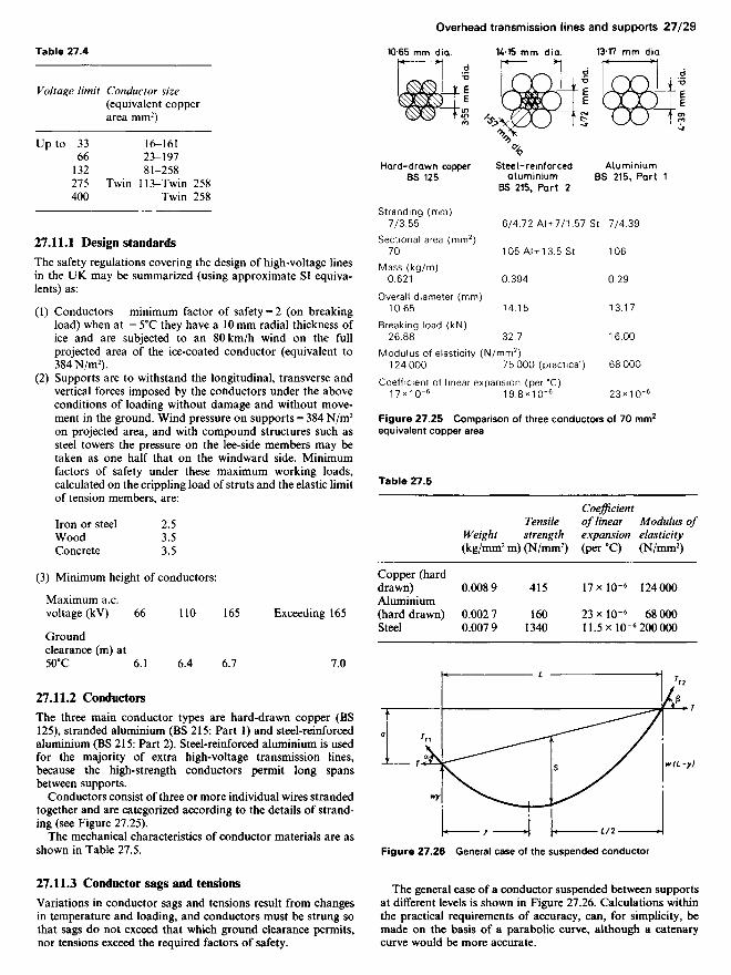
Table 27.4
Voltage limit Conductor size(equivalent copperarea mm2)
Up to 33 16-16166 23-197
132 81-258275 Twin 113-Twin 258400 Twin 258
27.11.1 Design standardsThe safety regulations covering the design of high-voltage linesin the UK may be summarized (using approximate SI equiva-lents) as:
(1) Conductors - minimum factor of safety = 2 (on breakingload) when at — 50C they have a 10 mm radial thickness ofice and are subjected to an 80km/h wind on the fullprojected area of the ice-coated conductor (equivalent to384 N/m2).
(2) Supports are to withstand the longitudinal, transverse andvertical forces imposed by the conductors under the aboveconditions of loading without damage and without move-ment in the ground. Wind pressure on supports = 384 N/m2
on projected area, and with compound structures such assteel towers the pressure on the lee-side members may betaken as one half that on the windward side. Minimumfactors of safety under these maximum working loads,calculated on the crippling load of struts and the elastic limitof tension members, are:
Iron or steel 2.5Wood 3.5Concrete 3.5
(3) Minimum height of conductors:
Maximum a.c.voltage (kV) 66 110 165 Exceeding 165
Groundclearance (m) at5O0C 6.1 6.4 6.7 7.0
27.11.2 ConductorsThe three main conductor types are hard-drawn copper (BS125), stranded aluminium (BS 215: Part 1) and steel-reinforcedaluminium (BS 215: Part 2). Steel-reinforced aluminium is usedfor the majority of extra high-voltage transmission lines,because the high-strength conductors permit long spansbetween supports.
Conductors consist of three or more individual wires strandedtogether and are categorized according to the details of strand-ing (see Figure 27.25).
The mechanical characteristics of conductor materials are asshown in Table 27.5.
27.11.3 Conductor sags and tensionsVariations in conductor sags and tensions result from changesin temperature and loading, and conductors must be strung sothat sags do not exceed that which ground clearance permits,nor tensions exceed the required factors of safety.
Hard-drawn copper Steel-reinforced AluminiumBS 125 aluminium BS 215, Part 1
BS 215, Part 2
Stranding (mm)7/3.55 6/4.72 AI + 7/1.57 St 7/4.39
Sectional area (mm2)70 105AI + 13.5St 106
Mass (kg/m)0.621 0.394 0.29
Overall diameter (mm)10.65 14.15 13.17
Breaking load (kN)26.88 32.7 16.00
Modulus of elasticity (N/mm2)124000 75000 (practical) 68000
Coefficient of linear expansion (per 0C)i7xicr6 i9.8*i(r6 23xicr6
Figure 27.25 Comparison of three conductors of 70 mm2
equivalent copper area
Table 27.5
CoefficientTensile of linear Modulus of
Weight strength expansion elasticity(kg/mm2 m) (N/mm2) (per 0C) (N/mm2)
Copper (harddrawn) 0.0089 415 17 x IQ-6 124000Aluminium(hard drawn) 0.002 7 160 23 x 10~6 68 000Steel 0.007 9 1340 11.5 x 10~6 200 000
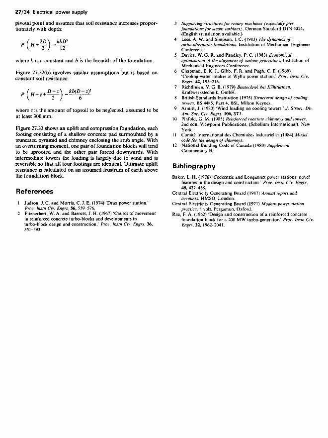
Figure 27.26 General case of the suspended conductor
The general case of a conductor suspended between supportsat different levels is shown in Figure 27.26. Calculations withinthe practical requirements of accuracy, can, for simplicity, bemade on the basis of a parabolic curve, although a catenarycurve would be more accurate.

Symbols and definitions for Figure 27.26
General Conductor data
L = span (horizontal A= actual cross-sectionaldistance between area of conductorssupports) d= overall diameter of
S= sag (distance measured conductorin the direction of the E= modulus of elasticityresultant load between of complete conductor,the conductor and the Virtual modulus formidpoint of a straight composite conductorline joining the two of materials a and bsupports) = Em + E
T= tension (horizontal a . b where* r*u m+lcomponent 01 the r
• A \ A area of atension under load vr, m = ^r, . .r area of bbeing uniform ffi . . f . .., & , . c= coefficient of linearthroughout any one . ~ .,& J expansion of complete
~ . .- i . • conductor.TT = tangential tension ... , ~ . ~T / f i * • * Virtual coefficient for a(actual tension at any . ,given point in a composite conductor
j . ., ot materials a and bconductor in the , „ ,,. A . r Al where E and m are asdirection or the ,tangent to the curve)
w= resultant load per = cdE/n + cbEb
metre of conductor mE.d + Eb
from vertical load of C1 = a constant = ^/EA /24self-weight + ice (if C2 = a constant = cEApresent) and horizontalwind load
a= difference in level ofadjacent supports
y = horizontal distance oflowest point of curvefrom lower support
t= temperature rise frominitial to finalconditions
Formulae for Figure 27.26„ H^
87 (27.1)
852 W3Z/3
Length of conductor = L + -^j- = L + ̂ p ^7 2)
(C1W1LV- T_(C^L\^_\n^) Tl \ Tt ) r' + Q' (27.3)
where the suffixes to W1T1 and W2T2 denote conditions at initialand final temperature respectively
= L _ f l Ty 2 wL (27.4)
Vertical reaction at higher support = w(L—y)
Vertical reaction at lower support = wy
Example 27.1 To determine the maximum sag at 5O0C of asteel-reinforced aluminium conductor of 100mm2 nominal alu-minium area (6/4.72 mm aluminium+ 7/1.57 mm steel) on a
span of 20Om. Factor of safety = 2.0 on breaking load with10 mm radial thickness of ice at - 50C and 80 km/h wind.
The sequence of calculations is as follows:
(1) Evaluate the conductor data (see Figure 27.25)
A = 105 mm2 Al+ 13.5 mm2 Steel= 118.5 mm2
d= 14.15 mm; breaking load = 32.7 kN
_ _ (EA\ 1/2_ /7500Ox 118.5X 1^2
C{~V2A) ~\ 24 J ~6°9
C2 = cEA=\9.8* 10 6 x75000x 118.5=176
/= 5O0C-(-50Q = 550C
(2) Calculate the initial tension T1 in the cable at -50C, theresultant load in the conductor w, at — 50C and W2 at 5O0C
T1 = initial tension at — 50C
breaking load _32,TkN =
factor of safety 2
Horizontal wind load = 384 ( —T7^— )\ 1UUU /
= 13.2N/m
Weight of ice (at 0.91 g/cm3) on conductor at - 50C
0.91 A r/34.15\2 /34.15V~l inn=ToooxTLl-ir) -(TO-) J X 1 0 °= 0.686 kg/m
Total weight = ice + self weight
= 0.686 + 0.394
= 1.08 kg/mHence:
w, = [13.22 + (9.9x 1.08)2]1/2
= 17N/m
W2 = load due to self weight
= 9.9 x 0.394 = 3.9 N/m
(3) From Equation (27.3) find horizontal tension T2 at 5O0C
(C^L\~_ /C1W1LV( T2 ) T> -\—) r' + C2/
(609X^X2Q°)2-r2= (6Q9X6
13
75
X0
20°)2-16350+176x5:
(«!«)•-,.,.„,

T2 is solved by trial and error using a slide rule. In this caseT2 = 4100.
(4) From Equation (27.1):
Sag S at 5O0C = ̂8/2
_3.9x2002
8x4100
= 4.75m
27.11.4 Supports
The configuration of supports (but not necessarily the form andmaterial used) depends initially on the electrical requirements ofnumber of circuits, conductor size and type, insulation andclearances, and on the arrangement of conductors and earthwires. The structural design of supports is related to the imposedloads: (1) horizontal transverse; (2) horizontal longitudinal; (3)vertical; and (4) wind and ice loads.
27.11.4.1 Horizontal transverse loads (P)
(1) Wind on bare or ice-coated conductors. Calculated on thesupport 'wind span' = half the sum of the adjacent spanlengths (see Figure 27.27). (PJ
(2) Wind on supports. For square-lattice structures, wind on theleeward face is taken as half that on the windward face; thisshielding factor decreases with rectangular shapes until thefull wind is taken on both faces. On cylindrical members,wind pressure is taken on 0.6 of projected area. (Ps)
(3) Conductor tension at line deviations.
r\Transverse load = 2 T sin ̂
where O is the angle of deviation and T is the maximumconductor tension (see Figure 27.27) (P2)
27.11.4.2 Horizontal longitudinal loads (T)
(1) Full conductor tension at line terminals. (T)(2) Out-of-balance conductor tensions due to broken conduc-
tors or earthwires. At supports with suspension insulators, areduced conductor tension, usually 70%, is allowed for the
swing of insulators into the unbroken span. (0.7 T or T)(3) Out-of-balance conductor tension at angle or section posi-
tions. Only encountered in special cases, e.g. change fromsingle to double earthwires. (T^)
27.11.4.3 Vertical loads (V)
(1) Weight of bare or ice-coated conductors calculated on basisof support 'weight span' (from Equation (27.4)). (KJ
(2) Weight of insulators, etc. (V)(3) Support weight. (KJ
27.11.4.4 Wind and ice loads
The relationship between wind velocity (K km/h) and pressure(P N/m2) may be taken as:
Flat surfaces P =0.1 K2
Round surfaces (e.g. conductors) P = 0.06 K2
Figure 27.27 indicates the locations relative to the conductor inwhich the main types of support are used, i.e. intermediate,angle and terminal.
The structural form and materials of supports may be classi-fied as:
Single or composite wooden polesSingle or composite reinforced concrete and prestressed con-crete polesSteel tubular polesNarrow-base towers - lattice structures of rolled steel and
tubular sections, with single blockfoundations, increasingly with theuse of guy wires
Broad-base towers - steel lattice structures, with a separatefoundation for each leg (Figures 27.28and 27.33).
27.11.5 Design of broad-base towers
The following description applies chiefly to the design sequencefor broad-base towers, but the principle applies equally to othertypes.
With the electrical requirements resolved, the first step indesign of the supports is to decide upon the 'standard span', i.e.the most economic span assuming level ground. Exploratorydesign is concentrated on the intermediate supports (being themajority) and the following interdependent factors are taken
Figure 27.27 Horizontal loading relative to support positions
I n t e r m e d i a t e
P » P w (based on L |^ 2 )2
Termina l
Pw (basedon Ll)

Figure 27.29 Wire clearance diagram
into consideration to determine the general outline and thearrangement and height of the cross arms:
(1) Height to bottom conductor, which is the minimum speci-fied ground clearance, plus the maximum sag of the conduc-tor.
(2) Conductor spacing:
(a) Minimum horizontal and vertical spacing to provide
adequate midspan clearance dependent upon spanlength, sag and voltage, as well as factors such as iceshedding overcome by offsetting the conductors(Figure 27.28).
(b) Minimum live-metal-to-earth clearance, taking intoaccount the maximum swing of suspension insulatorsrelated to horizontal (Pw and T) and vertical (Kw andKJ) conductor loading. Figure 27.29 shows a wireclearance diagram; the live-conductor-to-earthed-sup-port clearances are decided according to the transmis-sion voltage.
(c) Earthwire spacing. Protection against lightning isobtained by shielding the conductors with an overheadearthwire suitably earthed at the structures to interceptand earth-direct lightning strokes. The shielding angleV/ is preferred to be not greater than 30°. The earthwiresag should not exceed that of the conductor and therelative spacing is determined by the shielding angle(Figure 27.29).
When the standard span has been decided, the most economictower to meet the prescribed conditions can be designed. For theintermediate tower, the basis of loading may be:
Wind span = greatest wind load = wind load on standardspan+10%Weight span = greatest wind load = weight load from stan-dard span+100%Maximum length of span = length of standard span 4- 40%
Final design is undertaken graphically by means of stressdiagrams, usually on the basis of working loads. The factors ofsafety (e.g. in the UK 2.5 under normal, and 1.5 under broken-wire conditions) are applied when the individual member loads
Figure 27.30 Loading diagram for a double-circuit intermediatetower
Figure 27.28 Broad-base tower
Earthwire
Arcing hornConductor
Suspensioninsulator
Earthwire
Suspensioninsulator

Figure 27.31 Torsion loading
are tabulated. Vertical loads are omitted from the stress dia-grams, but at the tabulations are shared equally over the fourmain legs.
A typical loading diagram shown in Figure 27.30 includes acondition of any one conductor or the earthwire broken (shownin brackets for a top conductor but it must be consideredindividually at each conductor and earthwire position). Notethe proportionate reductions of Pw and Kw for the broken-wirecondition and the equal distribution at cross-arm level of thewind load Ps on the tower.
Stability under torsion loads due to broken wires depends onthe tower being adequately braced in plan, essentially at cross-arm level but possibly at other levels dependent on particulardesign features. Figure 27.31 shows the reactions for a tower ofsquare cross-section of the type shown in Figure 27.30.
27.11.6 Foundations
The forces to be resisted by overhead-line support foundationsresult largely from overturning moments, with a consequentemphasis on horizontal and uprooting forces. The types offoundation can be broadly classified as:
Direction of overturning
Figure 27.32 Side-bearing foundations
(1) Side bearing - resistance depends on horizontal soil reac-tions, i.e. single foundations used for unstayed poles andnarrow-base towers.
(2) Uplift and compression - resistance depends on vertical soilreactions, i.e. in the case of broad-base towers where each ofthe four legs has a separate foundation, and in the case ofstayed poles.
Figure 27.32 shows the pressure distribution assumed (neglect-ing the small values of direct horizontal shear) in two formulaeused for pole and shallow concrete block side-bearing founda-tion. In Figure 27.32(a) (parabolic distribution) the pressuredeveloped is based on the horizontal movement relative to the
Ground level
Stub angle
Square concrete'chimney'
Angle cleat
Figure 27.33 Uplift and compression foundations
Ground level
Compression
Vsquare
pivotal point and assumes that soil resistance increases propor-tionately with depth:
'(»*¥)-«£
where A: is a constant and b is the breadth of the foundation.
Figure 27.32(b) involves similar assumptions but is based onconstant soil resistance:
,(^.Uf]-UBfZ
where z is the amount of topsoil to be neglected, assumed to beat least 300 mm.
Figure 27.33 shows an uplift and compression foundation, eachfooting consisting of a shallow concrete pad surmounted by atruncated pyramid and chimney enclosing the stub angle. Withan overturning moment, one pair of foundation blocks will tendto be uprooted and the other pair forced downwards. Withintermediate towers the loading is largely due to wind and isreversible so that all four footings are identical. Ultimate upliftresistance is calculated on an assumed frustrum of earth abovethe foundation block.
References
1 Judson, J. C. and Morris, C. J. E. (1974) 'Drax power station.'Proc. Instn Civ. Engrs, 56, 559-576.
2 Fitzherbert, W. A. and Barnett, J. H. (1967) 'Causes of movementin reinforced concrete turbo-blocks and developments inturbo-block design and construction/ Proc. Instn Civ. Engrs, 36,351-393.
3 Supporting structures for rotary machines (especially pierfoundations for steam turbines). German Standard DIN 4024.(English translation available.)
4 Lees, A. W. and Simpson, I. C. (1983) The dynamics ofturbo-alternator foundations. Institution of Mechanical EngineersConference.
5 Davies, W. G. R. and Pandley, P. C. (1983) Economicaloptimisation of the alignment of turbine generators. Institution ofMechanical Engineers Conference.
6 Chapman, E. K. J., Gibb, F. R. and Pugh, C. E. (1969)'Cooling-water intakes at Wylfa power station/ Proc. Instn Civ.Engrs, 42, 193-216.
7 Richtlinien, V. G. B. (1979) Bautechnik bei Kuhltiirmen.Kraftwerkstechnik, GmbH.
8 British Standards Institution (1975) Structural design of coolingtowers. BS 4485, Part 4, BSI, Milton Keynes.
9 Armitt, J. (1980) 'Wind loading on cooling towers/ J. Struct. Div.Am. Soc. Civ. Engrs, 106, ST3.
10 Pinfold, G. M. (1985) Reinforced concrete chimneys and towers.2nd edn. Viewpoint Publications, (Scholium International), NewYork.
11 Comite International des Cheminees Industrielles (1984) Modelcode for the design of chimneys.
12 National Building Code of Canada (1980) Supplement.Commentary B.
Bibliography
Baker, L. H. (1970) 'Cockenzie and Longannet power stations, novelfeatures in the design and construction/ Proc. Instn Civ. Engrs,48, 427^58.
Central Electricity Generating Board (1987) Annual report andaccounts. HMSO, London.
Central Electricity Generating Board (1971) Modern power stationpractice. 8 vols. Pergamon, Oxford.
Rae, F. A. (1962) 'Design and construction of a reinforced concretefoundation block for a 200 MW turbo-generator/ Proc. Instn Civ.Engrs, 22, 1962-2041.