fig 2.9 guidance road markings - 2 may 2012 sartsm vol 2
TRANSCRIPT

MAY 2012 SARTSM – VOL 2 ROAD MARKINGS
INTRODUCTION 2.1.11
Fig 2.9 Guidance Road Markings - 2

SARTSM – VOL 2 ROAD MARKING MAY 2012
INTRODUCTION 2.1.12
(continued from page 2.1.2)
(a) to the smallest practical "scale" which permits several
hundred metres of roadway to be illustrated in sections on
an A3 page (a 3,7 m lane is shown as 2.5 mm wide) - this
scale limits the level of detail - examples may extend to two
facing A3 pages;
(b) an intermediate "scale" which permits detail such as
roadstuds to be shown effectively (a 3.7 m lane is shown as
10 - 12 mm wide);
(c) a larger "scale" of approximately 1/200 which permits
greater clarity of dimensional detail (a 3,7 m lane is shown
at 18,5 mm).
4 Figures in Section 2.7 which deal with individual arrow, symbol
and letter dimensions are generally drawn to a scale stated in
the figure.
5 Whenever practical the colour of all road markings is given by a
"black and white" colour shading convention. This is shown in
Figure 2.10, Detail 2.10.1.
6 Whenever it has been considered necessary to clarify the
direction of travel of traffic in relation to the road markings in the
figure this is indicated by means of one or more black triangular
arrows. To avoid confusion no other road marking arrows are
shown shaded black. An example is illustrated in Detail 2.10.2.
7 In figures which depict significant lengths of roadway the full
size width of the road marking lines and their colours are shown
within circles which are located at a convenient "end" of a
section of roadway. A typical example is shown in Detail 2.10.3.
8 In the smaller scale figures the road marking number and name
are both given outside the indication of the roadway. In the
larger scale figures the number and name may sometimes be
separated so that the number appears within the roadway and
the name is kept to the outside of the detail. It is recommended
that detailed design drawings being prepared in the drawing
office use numbers only, following the method of including the
road marking number within the roadway, as close as possible
to the actual marking - see Detail 2.10.3.
9 The more commonly used longitudinal broken line markings
may be specified as "Reduced", "Standard", or "Extra". The
functions of these options are discussed in the relevant
subsections but the typical examples include the appropriate
word next to the marking or the marking name, according to the
availability of space - see Detail 2.10.4.
10 Whenever practical in terms of the "scale" of the figure
roadstuds are shown. The roadstuds are illustrated by the
convention shown in Detail 2.10.5 and in the larger details they
are colour coded in terms of the convention given in Detail
2.10.1. The use of roadstuds is, however, optional.
11 The provision of kerbing is an option which is fairly commonly
exercised in both rural and urban situations. When the scale of
the figure permits, kerbing is illustrated by two thin closely
spaced lines. When this convention is used in the figures,
black-and-white KERBFACE marking GM8 is normally shown.
The use of marking GM8 is optional.

MAY 2012 SARTSM – VOL 2 ROAD MARKINGS
INTRODUCTION 2.1.13
Fig 2.10 Figure Conventions

GENERAL PRINCIPLES 2.2.1
MAY 2012 SARTSM – VOL 2 ROAD MARKINGS
2.2 GENERAL PRINCIPLES
2.2.1 General
1 Road markings perform a very necessary function by
conveying requirements and information to drivers which might
not be possible by means of road signs. They may often be
visible when signs are obscured and are able to provide
message continuity to drivers of moving vehicles, which may be
difficult and costly to achieve using road signs.
2 Road markings have the limitation that they may be obliterated
under adverse weather conditions. Their conspicuity is
impaired, often significantly, when wet or dirty and their
durability depends to a great extent on the quality of their
application to the road surface and on their exposure to traffic
wear.
3 The effectiveness of road markings will deteriorate rapidly if
their application is not adequately specified and controlled.
When road markings have poor durability the road authority is
forced to re-mark more frequently which results in poor
cost-efficiency. If road markings are not durable or well
maintained the accident potential for sections of roadway may
be significantly increased, with further adverse economic
effects. Road markings may be provided in a range of materials
in addition to the traditional paint. The initial installation cost of
many of these materials can be high, but they may be
sufficiently durable that, in spite of this, their performance is
cost-effective.
4 This section deals briefly with the various factors relevant to the
provision of effective road markings. Greater detail on some of
these topics may be found in Volume 1, Chapters 1 and 7.
2.2.2 Figure Dimensions
1 The road marking figures contained in this chapter must be
considered as typical. In this context the indication of lane, or
even roadway width dimensions is rarely given in the figures.
This is because, in reality, there is not a wide range in normal
lane width specification, although most road authorities have
their own standard requirements.
2 Longitudinal roadway dimensions are, conversely, given in
many figures. These commonly relate to geometric
components of a road design, as depicted by the road
markings. As such the dimensions may cover elements such
as:
(a) changes in road width and/or number of lanes;
(b) development of exclusive turning lanes;
(c) the length of such turning lanes;
(d) junction geometry.
The dimension standards given in the figures can generally be
considered representative of design for either high speed
and/or high standard environments. The use of these
standards and the appropriate dimensions in the figures
should not be taken as representing an obligation to
provide such standards on the roadway for any specific
site or design. The ultimate decisions on dimensions must
be made as part of the geometric design process for the
site.
3 In certain of the larger scale figures individual road markings
may occasionally be dimensioned to indicate which size, out of
a range of sizes, is appropriate in the specific circumstances. In
addition all individual arrows, symbols, and letters are fully
dimensioned in Section 2.7 - Enhanced Standard Details (see
also Subsections 2.1.5 and 2.2.3).
2.2.3 General Principles of Road Marking Dimensions
1 The width and length of many types of road marking may be
varied. However, the majority have recommended and/or
mandatory minimum dimensions. The mandatory minimum
dimensions are contained in Schedule 3 of the Road Traffic
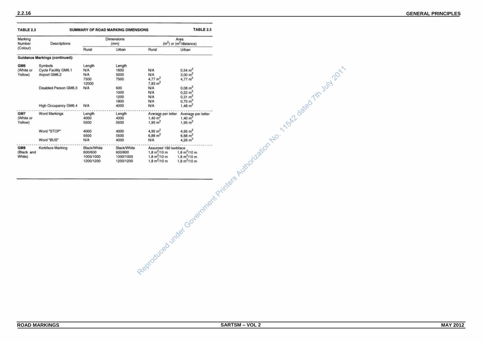
Act, Act 93 of 1996. These dimensions are summarised in
Table 2.3.
2 The minimum width of any line marking, as stated in Act 93 of
1996, shall be 100 mm.
3 All broken line markings are described by a LINE-TO-GAP
RATIO and recommended dimensions of line and gap lengths
are given in Table 2.3. Longitudinal broken line markings are
designed for convenience to be set out in repeating
MODULES. A module may comprise one or several
line-plus-gap repetitions.
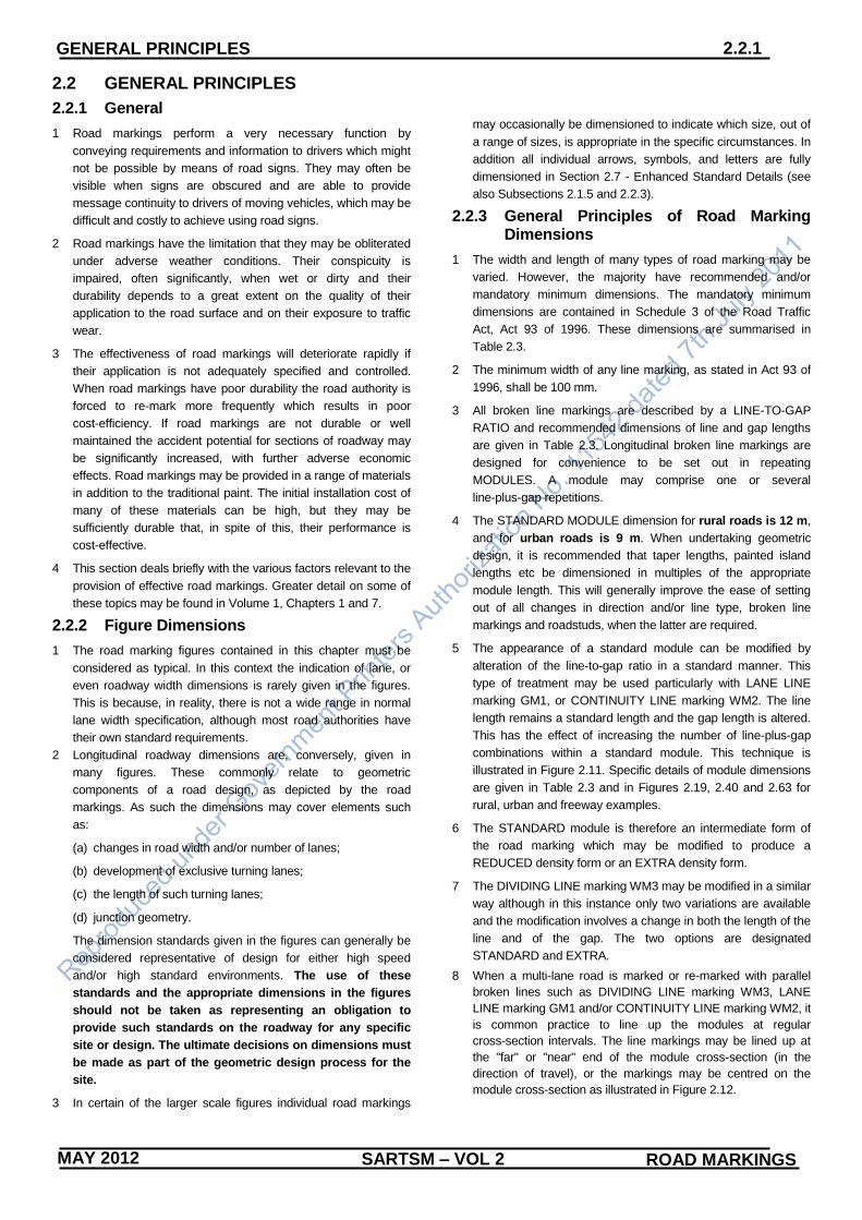
4 The STANDARD MODULE dimension for rural roads is 12 m,
and for urban roads is 9 m. When undertaking geometric
design, it is recommended that taper lengths, painted island
lengths etc be dimensioned in multiples of the appropriate
module length. This will generally improve the ease of setting
out of all changes in direction and/or line type, broken line
markings and roadstuds, when the latter are required.
5 The appearance of a standard module can be modified by
alteration of the line-to-gap ratio in a standard manner. This
type of treatment may be used particularly with LANE LINE
marking GM1, or CONTINUITY LINE marking WM2. The line
length remains a standard length and the gap length is altered.
This has the effect of increasing the number of line-plus-gap
combinations within a standard module. This technique is
illustrated in Figure 2.11. Specific details of module dimensions
are given in Table 2.3 and in Figures 2.19, 2.40 and 2.63 for
rural, urban and freeway examples.
6 The STANDARD module is therefore an intermediate form of
the road marking which may be modified to produce a
REDUCED density form or an EXTRA density form.
7 The DIVIDING LINE marking WM3 may be modified in a similar
way although in this instance only two variations are available
and the modification involves a change in both the length of the
line and of the gap. The two options are designated
STANDARD and EXTRA.
8 When a multi-lane road is marked or re-marked with parallel
broken lines such as DIVIDING LINE marking WM3, LANE
LINE marking GM1 and/or CONTINUITY LINE marking WM2, it
is common practice to line up the modules at regular
cross-section intervals. The line markings may be lined up at
the "far" or "near" end of the module cross-section (in the
direction of travel), or the markings may be centred on the
module cross-section as illustrated in Figure 2.12.

SARTSM – VOL 2 ROAD MARKINGS MAY 2012
GENERAL PRINCIPLES 2.2.2
MAY 2012
9 Dimensions for the majority of symbols, arrows and letters
allow for the following general range of standard sizes
(lengths):
1,25 m : 2,5 m : 4,0 m : 5,0 m : 7.5 m.
It should be noted that certain arrows are not appropriate in all
the sizes indicated and others may be occasionally used in a
size outside the range. This information is given in Table 2.3.
10 WORD marking GM7, with a letter size of 5,5 m, has been
established for a very long time and many organisations have
this size of letter stencil or mask. The dimension of 5,5 m has
therefore been retained for GM7 letters in preference to a 5,0 m
size.
11 If it is required to mark on the road surface a symbol used
elsewhere in the road traffic sign system, it is recommended
that, to be effective, the symbol be elongated by a factor of at
least three times, whilst retaining the original width. These
criteria should only be used for experimental purposes, as
approved by the relevant Minister. The need for any such road
marking should be submitted to:
The Secretary
Route Numbering and Road Traffic Signs Sub-Committee
c/o Department of Transport
Private Bag X193
PRETORIA
0001.
2.2.4 Basic Design Principles
1 Road markings are provided to satisfy requirements for driver
guidance, in terms of the geometric arrangement of their
longitudinal and lateral alignment and location. They must, in
doing so, also be provided in an economically and
environmentally suitable way. Road markings should therefore
embody the following properties:
(a) good visibility by day and night;
(b) good skid resistance;
(c) durability;
(d) clarity of message;
(e) where appropriate, symbolic markings should be elongated
in the direction of movement of traffic;
(f) elongated markings should be sized (length) in relation to
the operating speed of traffic;
(g) short drying or application times to keep traffic disruption to
a minimum;
(h) low environmental impact (products shall not contain
substances banned under national or international
law).
2 The visibility of road markings depends on the observation
angle, the length of the marking and the contrast in levels of
light reflected by the marking and by the surrounding surfaces.
This LUMINANCE CONTRAST is considered to result from
conditions of identical illumination of the adjacent contrasting
surfaces. The luminance of a marking is dependent on the
amount of pigment, the presence of glass beads (which reduce
the luminance) and the method or manner of application. To be
visible, markings must contrast adequately with the surface
to which they are applied. For this reason it is sometimes
necessary to specify that a black outlining background be
applied to light coloured road surfaces before marking white or
yellow markings.
3 To improve contrast it is generally recommended that road
markings which have a night-time significance be made
retroreflective by the means of glass beads (ballotini), applied
either in a pre-application mixed form, or after the application of
a paint.
4 When the alignment and/or width of a roadway is altered due to
an increase or decrease in the number of lanes, or the
introduction or removal of a dividing island, or at a constriction,
it is commonly necessary to re-align the longitudinal road
markings. Such a change in alignment is achieved by shifting
the line marking laterally at a constant rate until it reaches the
new position. This rate of shift is generally referred to as the
TAPER RATE. In this context a "taper" can be considered to
occur either when the road is widening or narrowing.
5 For purposes of road marking a taper rate of 1 in 50 (or 1 metre
shift in 50 metres longitudinal distance) is considered "flat",
whereas a taper rate of 1 in 10 is considered "sharp". Subject
to the road space available the ends of the tapering section
may be softened, both visually and geometrically, by the
introduction of circular or parabolic curves. Such treatment is
more appropriate when using "sharp" taper rates but may also
be used with "flat" tapers on high speed roads.
6 The TAPER RATE to be used in a specific situation is
dependent on:
(a) the operating speed of traffic;
(b) whether only road markings are offset without similar
changes to the road edge or to kerbing;
(c) whether a channelizing or median island (or barrier) is
introduced as well as the shift in alignment.
7 Table 2.1 indicates a range of appropriate TAPER RATES.
When a change in alignment occurs simultaneously with the
introduction of an island (or barrier) the flatter taper rate quoted
should be used. When introduced into the traffic flow a narrow
island may be potentially more hazardous than a wider one,
therefore flatter taper rates are recommended for narrower
obstructions.
8 It is often difficult to adequately indicate through the road
markings that a road carries two-way traffic. This is particularly
the case when one-way and two-way roads closely follow on
another or join each other. Drivers can, in fact, have difficulty
putting the correct interpretation on what they see. Designers
should note and understand, the functional or operational
difference between longitudinal line markings used for the
separation of vehicles travelling in the same direction, and
those used for the separation of vehicles travelling in opposite
directions, even though the markings may be similar or even
identical in appearance. Designers should be careful to identify
such situations and be prepared to use design techniques such
as wider line thicknesses to add emphasis to the markings that
are most difficult to interpret.
(continued on page 2.2.6)

MAY 2012 SARTSM – VOL 2 ROAD MARKINGS
GENERAL PRINCIPLES 2.2.3
Fig 2.11 Typical Modules for Broken Line Markings

SARTSM – VOL 2 ROAD MARKINGS MAY 2012
GENERAL PRINCIPLES 2.2.4
MAY 2012
Fig 2.12 Lateral Alignment of Road Marking Modules
GENERAL PRINCIPLES 2.2.5
MAY 2012 SARTSM – VOL 2 ROAD MARKINGS
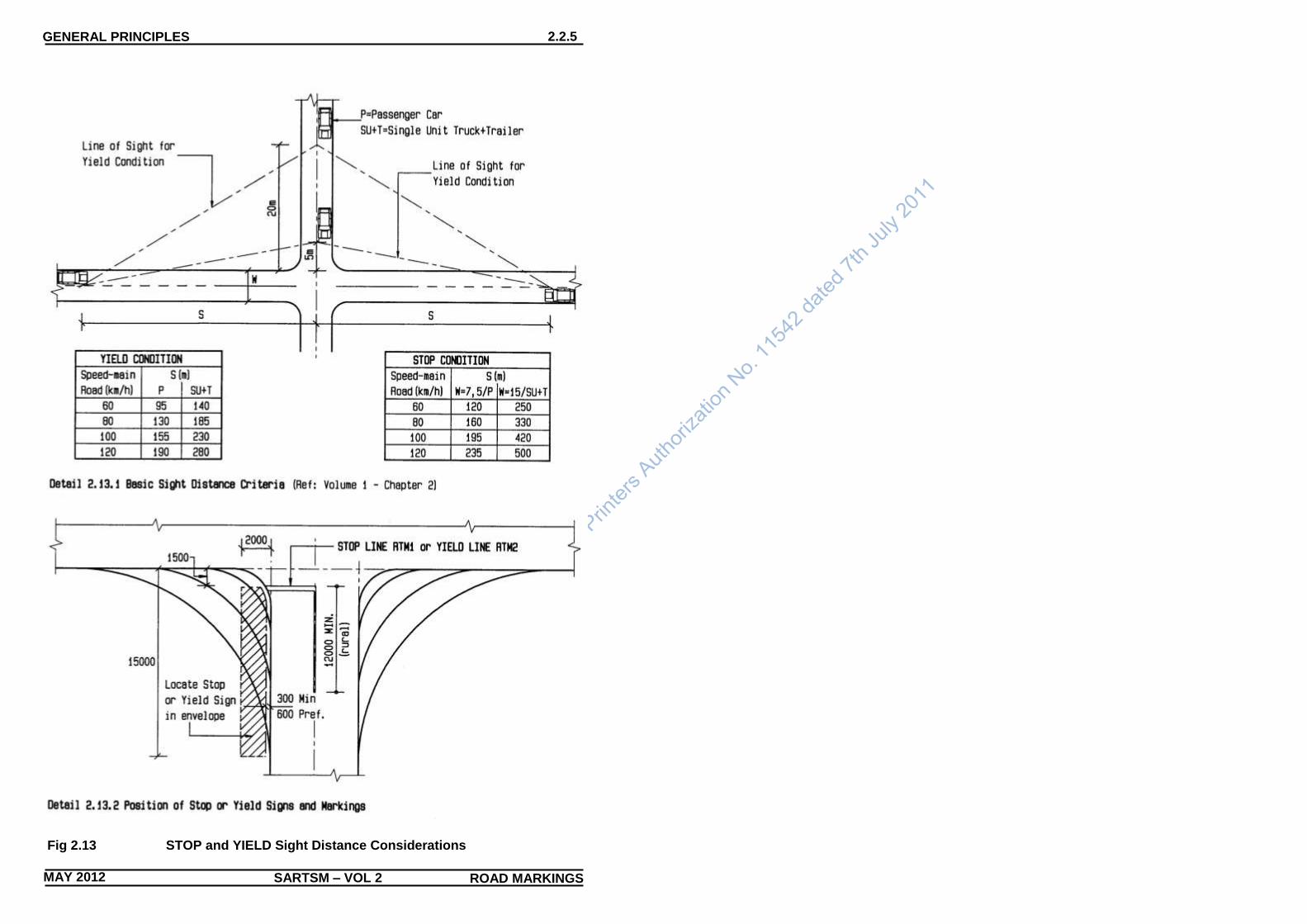
Fig 2.13 STOP and YIELD Sight Distance Considerations

GENERAL PRINCIPLES 2.2.6
SARTSM – VOL 2 ROAD MARKINGS MAY 2012
(continued from page 2.2.2)
9 Two of the most common groups of road marking applications,
used in all environments, and covered in this subsection because
of their basic importance, are:
(a) STOP LINE marking RTM1 or YIELD LINE marking RTM2;
(b) the marking of DIVIDING LINE WM3, NO OVERTAKING LINE
RM1 and NO CROSSING LINES RM2 in relation to each
other.
10 Figure 2.13 gives details of the sight distance considerations
appropriate to the decision to mark a STOP LINE marking RTM1
or a YIELD LINE marking RTM2 at an intersecting side road. The
position of markings RTM1 and RTM2 are very much related to
the positions of STOP sign R1 and YIELD sign R2 respectively.
However, when lines RTM1 or RTM2 are marked it is the marking
at which drivers have to stop or yield (not the sign). The markings
in particular, must therefore be positioned with adequate sight
distance in mind. The minimum width requirements specified for
markings RTM1 and RTM2 in Table 2.3 should be noted.
11 The marking of a line between streams of traffic travelling in
opposite directions is perhaps the most commonly used road
marking on our roads. Which line should be used is dependent on
the need to control overtaking manoeuvres. When traffic volumes
are low, operating speed is acceptable, and visibility is good, the
"centre" of the road may be demarcated by a DIVIDING LINE
marking WM3 which permits overtaking (with due regard to safety)
in both directions of travel. A DIVIDING LINE shall be marked on
all permanently surfaced rural roads with a running surface width
of 5,5 m or more. A DIVIDING LINE may be marked on rural or
urban roads of lesser width in the interests of safety, subject to
engineering assessment. Marking WM3 may be used
economically for relatively short distances on roads under 5,5 m
width. When traffic volumes are low, likely situations for such use
include sharp horizontal and/or vertical alignment, the approaches
to road junctions, railway crossings, or bridges and culverts, in
order to warn drivers to pay particular attention to possible
on-coming traffic. Traffic volumes above the very lowest levels will
warrant road widths in excess of 5,5 m, in which case the use of a
NO OVERTAKING line will most likely be warranted in the types of
situation described above.
12 When warranted a DIVIDING LINE should be replaced by either a
NO OVERTAKING LINE marking RM1 or a NO CROSSING LINE
marking RM2.
13 Apart from the visual impact of the two line types RM1 and RM2,
the basic operational difference between them is that NO
OVERTAKING LINE RM1 permits drivers to cross the line to gain
access to land on the opposite side of the line, and vice versa, and
with due regard to safety to pass a stationary obstruction in the
road. In contrast the only circumstance under which a driver may
cross a NO CROSSING LINE RM2 is to pass a stationary
obstruction in the road if it is safe to do so.
14 A prohibition on overtaking may be marked according to one of
three systems, namely (see Figure 2.14):
(a) a "Single Line System" in which a DIVIDING LINE WM3 is
replaced by a single NO OVERTAKING LINE RM1;
(b) a "Hybrid System" in which a section of NO OVERTAKING
LINE RM1 is added to the left of the DIVIDING LINE - this
prohibits overtaking only in the direction of travel on the side of
the RM1 marking - overtaking is permitted in the direction of
travel on the side of marking WM3 ( this type of combined line
marking may be replaced over some sections of the road by a
single RM1 marking, hence the term "hybrid");
(c) a "Three Line System" which retains the DIVIDING LINE
throughout the section of road on which the prohibition is
marked - where NO CROSSING is required two solid
continuous white lines are marked, one on each side of the
dividing line - if overtaking is to be permitted in one
(continued on page 2.2.10)
TABLE 2.1 NOMINAL TAPER RATES FOR LONGIITUDINAL LINES TABLE 2.1
Operating Speed (km/h)
Taper Rate for Line Shift Without
Kerbed Island
1 in **
Taper Rate for Line Shift Preceding Kerbed Island
1 in **
Width of Kerbed Island
600 mm – 1,25 m 1,75 m – 2,5 m 3 m or more
30 20 Rural 50 20
10 Urban 25 10
50 25 Rural 50
20 15 Urban 30
60 35 Rural 50
25 20 Urban 35
80 45 Rural 50
35 30 Urban 45
120 50
50 40 35
(Continued on page 2.2.8)
scribed in the Road Traffic Act, Act93 of 1996.

GENERAL PRINCIPLES 2.2.7
MAY 2012 SARTSM – VOL 2 ROAD MARKINGS
Fig 2.14 Line Combinations Incorporating No Overtaking Markings
NOTES: (1) The marking arrangements shown above indicate
“centre line” treatments for two-way roadways. To
avoid risks of confusion (particularly in a legal
context) the terms “centre line” and “barrier line”
are no longer used. The line separating opposing
streams of two-way traffic may comprise a
DIVIDING LINE marking WM3 (permtting
overtaking), a NO OVERTAKING LINE marking
RM1 (prohibitin overtaking but permitting crossing),
or a NO CROSSING LINE marking RM2
(prohibiting overtaking and crossing), or some
combination of these lines.
(2) Details 2.14.1 and 2.14.2 show systems of line
marking between opposing streams of traffic which
involve the replacement of DIVIDING LINE wm3
by NO OVERTAKING LINE RM1.
(3) Detail 2.14.3 shows a system where, in effect, two NO OVERTAKING LINES RM1 added to DIVIDING LINE WM3, create a NO CROSSING LINE RM2. With such a system it is necessary to discontinue the marking if it is required to give access in a local situation to a property or side road (see Subsection 2.3).
(4) Markings WM3, RM1 and RM2 may be used with or wotout LEFT EDGE LINE marking RM4.1, or on a multi-lane road they may be used with LANE LINE marking GM1.

SARTSM – VOL 2 ROAD MARKINGS MAY 2012
GENERAL PRINCIPLES 2.2.8
(Continued on page 2.2.10) Fig 2.15 No Overtaking Lines for Vertical Curves

GENERAL PRINCIPLES 2.2.9
MAY 2012 SARTSM – VOL 2 ROAD MARKINGS
Fig 2.16 No Overtaking Lines for Horizontal Curves
NOTES: (1) An assessment of the need for NO OVERTAKING LINE RM1
should be undertaken for both directions of travel and for horizontal and vertical curvature. Marking RM1 should then be provided according to one of the three systems described in paragraph 2.2.3.14. If the “Three Line System” is used sections of NO CROSSING LINE may result (see Figure 2.14).
(2) Figure 2.15 gives details of minimum Barrier Sight Distance warrants for the provision of NO OVERTAKING LINES. A
Minimum diistance between successive lengths of markings RM1 or RM2 of 120 m is recommended, whether the lines are in the same direction or in opposite directions. Such overtaking lengths should be checked for adequacy by engineering assessment.
(3) On horizontal curves minimum Barrier Sight Distance should be assessed based on the line of sight not encroaching beyond the shoulder break point.

SARTSM – VOL 2 ROAD MARKINGS MAY 2012
GENERAL PRINCIPLES 2.2.10
(continued from page 2.2.6)
direction only for some distance the appropriate solid "third" line is
discontinued, permitting overtaking by traffic travelling adjacent to
the DIVIDING LINE.
15 Marking of NO OVERTAKING LINE RM1 and/or NO CROSSING
LINE RM2 is warranted where the Barrier Sight Distance between
a point 1,05 m high (equivalent to eye height) and a point 1,30 m
high (equivalent to vehicle height) on vertical or horizontal curves
is less than the value given in Figure 2.15. The Barrier Sight
Distance allows sufficient time for two vehicles approaching each
other in a head-on situation to stop if should be left with no other
option for avoiding action. This distance therefore approximates to
twice the Stopping Sight Distance.
16 The length of a NO OVERTAKING LINE RM1 depends on
whether its principle use is for traffic control purposes (commonly
at junctions), or for reasons of limited sight distance (commonly
between junctions). Figures 2.15 and 2.16 give details of the
setting out of NO OVERTAKING LINES for vertical curves and
horizontal curves respectively. Table 2.3 indicates minimum and
recommended minimum lengths of NO OVERTAKING LINE RM1
and NO CROSSING LINE RM2 when these are used at junctions.
Information on recommended minimum lengths of these line
types, when used on sections of road between junctions, is given
in Figure 2.15. For more information on the positional design of
marking RM1 refer to Section 2.3 and Volume 1, Chapter 7.
2.2.5 Specifications
1 The specification of applied road markings, and the testing of such
markings for compliance to specification is not well developed.
Details given in this section are therefore for the guidance only of
any authority wishing to carry out testing.
2 SABS Specifications CKS 192-1971, CKS 501-1981 and SANS
731-1:2006 and 731-2:2006 refer for Drop-on Type Reflectorised
Road-marking Paint, High-build Non-skid Road-marking Paint and
Road-marking Paint respectively, and deal with the quality of paint
manufacture, and offer limited testing advice. They do not cover a
number of important properties of road marking paints, nor do they
cover other road marking materials, nor any application
specifications.
3 The annual cost to road authorities of re-marking roads within their
jurisdiction can be considerable. In order to ensure that, in the
interests of road safety, markings remain of an acceptable
standard, the effectiveness of such expenditure should be
carefully monitored. In order to achieve an adequate and
cost-effective quality of road marking it is recommended that road
authorities entering into contracts specify their requirements for
the road markings as applied to the relevant road surface or
surfaces, in addition to specifying the materials as manufactured.
The specification can cover the durability required from materials
by specifying an acceptable deterioration in quality over a period
of time. By specifying in such a manner authorities should be able
to establish parameters for the maintenance of road markings in
an efficient manner. Such specification can be made independent
of the actual road marking materials and tenders can be reviewed
in terms of the initial cost AND the time span performance likely
from different materials.
4 Factors which should be included in a specification of an applied
road marking material are :
(a) colour;
(b) luminance factor
(c) coefficient of retroreflection;
(d) skid resistance (particularly for urban areas).
5 It is common practice when painting road markings on a newly laid
bituminous surface to cater for the surface curing time by painting
two applications at closely spaced intervals. This factor must be
considered when writing contract specifications and when
assessing tenders.
2.2.6 Roadstuds
1 ROADSTUDS may be used to supplement road markings where
these are subject to conditions of below average visibility.
Roadstuds achieve their effectiveness because they project above
the road surface and they incorporate retroreflective lenses which
efficiently reflect the light from vehicle headlamps over
considerable distances.
2 Road authorities may adopt policies which require the use of
roadstuds universally or selectively. If a universal policy is adopted
consideration should be given to intensifying the application rate of
the roadstuds in areas where below average conditions are
predictable.
3 Occurrence of the following conditions, either separately or in
combination may warrant the selective or intensified use of
roadstuds:
(a) regular occurrence of mist, fog or rain resulting in:
(i) significantly reduced visibility;
(ii) reduced performance of conventional road markings due
to standing water;
(b) heavy traffic volumes resulting in:
(i) poor visibility due to glare from headlamps of on-coming
vehicles;
(ii) restricted forward vision due to traffic density (and
resultant close following distances)
(iii) rapid wear of conventional road markings;
(c) isolated low standard road design resulting from:
(i) changing vertical and/or horizontal alignment;
(ii) reduced carriageway width or lateral clearance to street
furniture;
(iii) a speed limit set well below the general limit for the class
of road, or an advisory speed displayed which is much
lower (>20%) than the general speed limit; (iv) poor surface water drainage
(Continued on page 2.2.12)

GENERAL PRINCIPLES 2.2.11
MAY 2012 SARTSM – VOL 2 ROAD MARKINGS
(d) hazardous sites, with documented accident records,
involving:
(i) T-junctions;
(ii) wrong-way travel;
(iii) complex lane layouts;
(iv) sharp curves;
(v) at-grade railway crossings;
(e) roadworks sites of significant time duration to demarcate:
(i) temporary road alignments;
(ii) temporary lane arrangements;
(iii) rapid lane indication after resurfacing;
(f) on all freeways.
4 It is essential that the meaning imparted by roadstuds, and
the guidance given by them, is consistent and predictable.
Only three colours of roadstud are permitted to supplement
road markings. The meanings to be conveyed by the three
colours, in conjunction with relevant road markings, are:
(a) RED shall mean PROHIBITION;
(b) YELLOW shall mean WARNING;
(c) WHITE shall offer GUIDANCE.
5 The functions of these permitted colours of roadstud are:
(a) RED:
(i) to supplement any road marking to indicate potential
"wrong way" driving situations;
(ii) in conjunction with a white NO OVERTAKING LINE
marking RM1;
(iii) in conjunction with a white NO CROSSING LINE
marking RM2;
(iv) in conjunction with a white RIGHT EDGE LINE
marking RM4.2;
(b) YELLOW:
(i) in conjunction with yellow road markings with the
exception of any application covered by
sub-paragraph 2.2.6.5 (a) (i);
(c) WHITE (or clear):
(i) in conjunction with white road markings with the
exception of any application covered by
sub-paragraph 2.2.6.5 (a) (i).
6 It is recommended that only roadstuds which comply with the
requirements of the South African Standard Specification
SANS 1442:2008 Roadstuds be used. Roadstuds may be
omnidirectional, uni-directional or bi-directional.
Omnidirectional
roadstuds are only appropriate where all-round visibility of the
stud does not conflict with the colour code or function
provisions detailed in paragraphs 2.2.6.4 and 2.2.6.5. The
most likely application of omnidirectional roadstuds to comply
with these requirements is with a LANE LINE marking GM1.
Uni-directional roadstuds may be specified for use in white,
yellow or red. Bi-directional roadstuds may be specified as:
(a) white/white;
(b) white/red;
(c) yellow/yellow;
(d) yellow/red;
(e) red/red.
7 When the conditions given in paragraph 2.2.6.3 are likely to
occur, either separately or in combination, it is recommended
that the use of roadstuds be considered particularly with the
following types of road marking:
(a) NO OVERTAKING LINE RM1;
(b) NO CROSSING LINE RM2;
(c) CHANNELISING LINE RM3;
(d) LEFT EDGE LINE RM4.1;
(e) RIGHT EDGE LINE RM4.2;
(f) PAINTED ISLANDS RM5;
(g) CONTINUITY LINE WM2;
(h) DIVIDING LINE WM3;
(i) REVERSIBLE LANE LINE WM4;
(j) ARRESTOR BED AHEAD WM9;
(k) LANE LINE GM1.
8 The use of roadstuds is generally NOT recommended in the
following circumstances:
(a) if they are likely to be a risk to cyclists;
(b) where traffic speeds are low;
(c) when road surfacing is planned in the near future;
(d) when street lighting is of sufficient standard to ensure
adequate night-time visibility;
(e) specifically across the exit point to freeway off-ramps and
the entry point from freeway on-ramps, and any other
similar situation where traffic leaves or joins a major
roadway in a free-flowing or merging manner.
9 When roadstuds are specified for use, they should be spaced
(continued on page 2.2.14)
TABLE 2.2 RECOMMENDED LONGITUDINAL ROADSTUD SPACING TABLE 2.2
Normal (m) Intermediate (m) Abnormal (m) Centre - Centre Centre - Centre Centre - Centre
Rural 24 12 6 Urban 18 9 3 Temporary 12 6 3 down to 1

SARTSM – VOL 2 ROAD MARKINGS MAY 2012
GENERAL PRINCIPLES 2.2.12
(Continued on page 2.2.14) Fig 2.17 Basic Details of Roadstuds on Two-Lane Two-Way Roadways

GENERAL PRINCIPLES 2.2.13
MAY 2012 SARTSM – VOL 2 ROAD MARKINGS
Fig 2.18
Roadstuds on Multi-Lane Roads

SARTSM – VOL 2 ROAD MARKINGS MAY 2012
GENERAL PRINCIPLES 2.2.14
(continued from page 2.2.11)
longitudinally in accordance with the recommendations in Table
2.2. The terms "Normal", "Intermediate" and "Abnormal" used in
Table 2.2 are general terms intended to offer a limited grading of
the severity of conditions which may warrant the use of
roadstuds.
10 In addition to the requirements of Table 2.2 roadstuds shall be
spaced so that there are no fewer than three roadstuds in each
longitudinal line are visible to drivers to adequately define the
alignment of the lines. When horizontal and/or vertical alignment
is of a low standard this need may require an upgrading from
Normal to Intermediate spacing, or Intermediate to Abnormal
spacing.
11 When commencing setting out of roadstuds over some distance
the position of the first transverse row of studs for edge lines,
lane lines, dividing line etc. should be determined from one of the
broken line types on the section of road i.e. a LANE LINE GM1 or
DIVIDING LINE WM3. From this first "cross-section", subsequent
roadstuds can be positioned at the appropriate modular spacings
on all longitudinal lines. Figures 2.17 and 2.18 illustrate basic
roadstud applications and colour codes.
12 When roadstuds are to be applied next to a continuous
longitudinal solid line marking the roadstuds should preferably be
placed 50 mm from the line on the side outside the travelled way.
This spacing may be reduced to 25 mm in exceptional cases.
13 The lateral separation between multiple longitudinal lines such as
NO OVERTAKING LINE RM1, DIVIDING LINE WM3 and NO
CROSSING LINES RM2, should be such that if a roadstud is to
be placed between any two parallel lines there should be a
minimum of 150 mm between the lines to allow a minimum
clearance between the lines and roadstuds of 25 mm.
14 When a longitudinal marking is more than 200 mm wide it is
recommended that two roadstuds of the appropriate colour be
placed side-by-side within 150 mm to 200 mm short breaks in the
line.
2.2.7 Materials and Maintenance
1 Road markings may be applied in a paint, plastic or bonded
sheet form. The texture and preparation of the road surface to
which markings are to be applied determine, to a great extent,
the effectiveness of the application, and therefore the life of the
markings.
2 Road marking paints may be applied in a range of thicknesses of
the order of 0,2 mm to 0,5 mm and are designed to be quick
drying. Thin application paints, with limited durability, are
appropriate only to lightly trafficked roads or roads likely to be
subjected to maintenance within the longer life of more
appropriate thicker application markings used on busier roads.
3 The skid resistance of painted markings can be low.
Specifications should ensure that adequate skid resistance will
be achieved, particularly for large areas of road marking such as
symbols or arrows, and that compliance with these specifications
actually occurs.
4 Thermo-plastic materials, although costly, can be cost effective,
particularly if used for transverse lines, pre-cut symbols or arrows
for areas with high traffic flows. Thermo-plastic materials may be
spray applied (1 mm to 1,5 mm thickness) or screed applied (up
to 3 mm thickness). Cold applied plastics are even more costly,
but their durability may still be cost effective under conditions of
extreme wear. Specially textured materials are available which
improve wet weather performance and durability, and quality
plastic materials generally have very good skid resistance
properties.
5 The following aspects should be considered by road authorities
when developing a systematic approach to road marking
maintenance:
(a) before re-marking, particularly after a road or street has been
constructed or re-surfaced, the functional need for all
markings which existed before the work should be assessed;
(b) if a marking has been deemed necessary, it is in the interest
of public safety that it be well maintained;
(c) the most cost effective form of maintenance need not
necessarily to be the re-marking of markings at ever shorter
intervals of time due to the labour cost component; other
options should be assessed on an economical basis;
(d) mechanical street cleaning and the washing of devices such
as guardrails (and their delineators) is used in several parts
of the world to extend replacement maintenance periods and
should be assessed from time to time for cost effectiveness.
2.2.8 Temporary Markings
1 Due to the difficulty in effectively erasing road markings it is
strongly recommended that the provision of temporary markings
be carefully planned with respect to the number of iterations
which may be necessary on any specific section of road, and the
materials to be used. Attention must be paid to the method of
removal of road markings, with particular regard to the
anticipated lighting conditions likely to prevail on the sector of
road. Under adverse conditions, such as a low angle of sunlight,
markings which have been erased may show up more clearly
than when they still existed as painted markings.
2 A lightly applied, non-emulsion paint such as PVA, which will
wear quickly under traffic operation, may be viable for short term
work. Short term work can also include situations where frequent
re-marking of a section of road is scheduled due to variations in
temporary traffic accommodations.
3 Temporary pre-formed, adhesive-backed tapes may be used,
particularly for smaller areas of application. These are designed
to be applied and lifted, and re-applied a number of times, and
can therefore be cost effective if used carefully. A black version
of this tape is available which can be used to temporarily
"blank-out" markings which could be confusing, particularly at
temporary changes in direction when lane, edge or dividing lines
would otherwise continue across the line of the deviation.
4 Temporary roadstuds, placed at closely spaced intervals, may be
used to simulate road markings. Such roadstuds are designed for
easy removal after use.
2.2.9 Warrants
1 Precise warrants for the use of road markings are not well
developed. Guidance is given in Volume 1, Chapter 7 in relation
to certain road markings. The following may be considered as
general warrants for the use of certain common road markings
(see also paragraph 2.2.9.2):
(Continued on page 2.2.16)

GENERAL PRINCIPLES 2.2.15
MAY 2012 SARTSM – VOL 2 ROAD MARKINGS
(a) a LEFT EDGE LINE marking RM4.1 is warranted on any
rural or urban roadway which has been provided with a
shoulder, particularly a surfaced shoulder, if a shoulder is
not surfaced marking RM4.1 may be applied within 150 mm
of the edge of surfacing to inhibit edge damage (250 mm if
roadstuds are to be provided);
(b) a RIGHT EDGE LINE marking RM4.2 is warranted on the
right side of all freeway carriageways carrying traffic
travelling in one direction only (Class A1 freeway), whether
the median is provided with a barrier or not; marking RM4.1
is also warranted on at-grade dual carriageways which
have a median that is not defined by barrier or
unmountable kerbs;
(c) a GUIDE LINE marking GM2 is warranted within a junction
when more than one turning lane is provided for the right or
left turning movements, even if one of the two lanes is a
shared turning and through lane;
(d) a CONTINUITY LINE marking WM2 is warranted when a
dedicated or exclusive turning lane is provided at a rural or
urban junction; marking WM2 is commonly also warranted if
LEFT EDGE LINE marking RM4.1 is dropped through the
opening of a wide (including bell-mouths) side road junction
(see examples in Sections 2.3 and 2.4).
2 When the following traffic control devices are used the indicated
road marking is also warranted:
(a) STOP sign R1 (and its derivatives) - STOP LINE marking
RTM1;
(b) YIELD sign R2, YIELD TO PEDESTRIANS sign R2.1,
and YIELD AT TRAFFIC CIRCLE sign R2.2 - YIELD LINE
marking RTM2;
(c)TRAFFIC SIGNALS - STOP LINE marking RTM1 AND
PEDESTRIAN CROSSING LINES marking RTM3;
(d) EXCLUSIVE PARKING BAY marking RM7 - appropriate
designatory letter RM7.1;
(e) BUS LANE RESERVATION sign R302, BICYCLE LANE
RESERVATION sign R304, HIGH OCCUPANCY VEHICLE
RESERVATION sign R336 or TRAM LANE
RESERVATION sign R339 - EXCLUSIVE USE LANE LINE
marking RM9;
(f) EXCLUSIVE USE LANE LINE marking RM9 - symbol
markings BICYCLE GM6.1 and HIGH OCCUPANCY
VEHICLE GM6.4, and WORD MARKINGS GM7;
(g) in advance of a mid-block pedestrian crossing - ZIG ZAG
ZONE LINES marking RM11;
(h) in advance of a railway crossing (see Chapter 7, Figure
7.4) - RAILWAY CROSSING AHEAD marking WM1;
(i) in advance of a lane drop - LANE REDUCTION ARROW
markings WM6;
(j) in advance of a NO OVERTAKING LINE marking RM1 or a
NO CROSSING LINE marking RM2 - NO OVERTAKING
LINE AHEAD marking WM8;
(k) in advance of an arrestor bed - ARRESTOR BED AHEAD
marking WM9;
(l) at a speed hump - NO OVERTAKING LINE marking RM1 and SPEED HUMP marking WM10.
SARTSM – VOL 2 ROAD MARKINGS MAY 2012
GENERAL PRINCIPLES 2.2.16

RURAL 2.3.1
MAY 2012 SARTSM – VOL 2 ROAD MARKINGS
ROAD MARKINGS ROAD MARKINGS
2.3 ROAD MARKING APPLICATIONS IN RURAL SITUATIONS
2.3.1 General
1 The examples of road marking applications illustrated in this
section fall broadly into two groups:
(a) those relating to the commonly long sections of road
between rural junctions comprising mainly longitudinal
regulatory and warning markings; and
(b) those used, often in addition to those in (a) above, at rural
road junctions.
2 Examples of applications of road markings in urban and
freeway situations are illustrated in Sections 2.4 and 2.5.
3 Situations such as climbing lanes are commonly found on
sections of rural road. If such a facility is required on a freeway
or in an urban area the detail given in Figures 2.34 or 2.35
should be adapted accordingly by, for instance, use of urban
broken line modules in place of rural modules.
4 In some instances the scale of an illustration may limit the
amount of detail which can be given. Where necessary,
additional enhanced, or enlarged, details are given in Section
2.7. These enhanced standard details are commonly
appropriate to several marking applications. In addition,
although this section contains specific examples of rural
applications of PAINTED ISLAND marking, this marking is
covered in detail in Section 2.7 by Figures 2.87 to 2.92.
2.3.2 Section Coverage
1 The examples of rural road marking applications covered in this
section start with the basic components and then cover the
following groups of application types:
(a) broken line patterns;
(b) longitudinal line markings;
(c) basic junction marking;
(d) the beginning and ending of dual carriageways;
(e) lane drops;
(f) painted islands.
2 There is the potential for much duplication of application
examples between various sections. This has been avoided as
much as is practical. If the user wishes to view a broader range
of examples those in other sections should be assessed. This
action may be particularly relevant in peri-urban or urban fringe
areas.
3 As part of the action to avoid duplication a number of very basic
principles are covered in Section 2.2. These principles have
been considered so basic as to apply throughout the road
network at virtually all levels. Typical subjects covered in
Section 2.2 which are relevant to rural road marking
applications are:
(a) alignment of lane markings on multi-lane roads (Figure
2.12);
(b) STOP and YIELD sight distances and sign location (Figure
2.13);
(c) tapers (Table 2.1);
(d) NO OVERTAKING LINE marking RM1 warrants (Figures
2.14 to 2.16);
(e) roadstuds (Subsection 2.2.6, Table 2.2 and Figures 2.17
and 2.18).
2.3.3 Specification and Materials Quantities
1 Detailed specifications are not covered but Subsection 2.2.5
gives limited guidance.
2 As an aid to measuring quantities of road markings, by area,
Table 2.3 lists areas by each standard size of individual
marking in m2, or for longitudinal markings by an appropriate
length i.e. m2/100 m. This table stretches over pages 2.2.6 to
2.2.16 and is arranged to fold out so that it can be visible
anywhere in the Chapter, or, in fact if the user is working with
specific road marking drawings.
3 It should be noted that the minimum width of any road marking
line is 100 m. The various application details give
recommended line widths in the manner illustrated in Figure
2.10. Road authorities may always use a wider line than
indicated in the details. If this option is exercised, however, it is
recommended that any line width differential indicated in a
detail be maintained.

SARTSM – VOL 2 ROAD MARKINGS MAY 2012
RURAL 2.3.2
2.3.4 Rural Longitudinal Road Markings
1 By far the greatest proportion of road markings on rural roads
are longitudinal road markings, either in the form of:
(a) broken line markings; or
(b) continuous line markings.
2 On rural roads longitudinal lines commonly separate traffic
travelling in opposite directions. Such lines are recommended
to be 150 mm in width on all but the lowest class roads. A line
separating opposing streams of traffic is generally referred as a
"dividing line". The following line types may be used for this
function:
(a) DIVIDING LINE marking WM3 (broken line);
(b) NO OVERTAKING LINE marking RM1 (continuous line);
(c) NO CROSSING LINE marking RM2 (double continuous
lines).
3 Figure 2.19 illustrates the longitudinal broken line types most
commonly used on rural roads. Broken lines should be marked
in a regular repeating modular pattern. The module length for
rural road markings is 12 m. Modular broken line markings
may be applied as STANDARD, REDUCED or EXTRA
MODULES. The decision to alter from one type of module to
another, or to choose one type of module instead of another,
may be warranted by factors such as:
(a) the need to economise where visual impact is not critical;
(b) the need for increased visual impact from road marking due
to horizontal or vertical curvature, high traffic volumes or a
change in the roadway cross-section or lane configuration;
(c) the need to emphasize to road users the difference
between functionally different, but visually similar, types of
road markings;
(d) the use of a progressive increase in density of marking
approaching a point of divergence, convergence, or
potential conflict of traffic.
4 Figures 2.20 and 2.21 illustrate various aspects of longitudinal
line markings used in combination with each other. These start,
in Detail 2.20.1, with the application of SHOULDER
DELINEATOR devices D1, which are classified as a form of
road marking due to their function. These devices may be
specified for gravel roads or for roads with a narrow surface
(under 5,5 m in width) in order to give an indication of road
alignment. The spacing between delineators should be reduced
for shorter radius curves.
5 Details 2.20.2 to 2.20.7 show a progressive build up in line
marking intensity with increasing roadway width through the
provision of surfaced shoulders to a dual carriageway
cross-section.
6 Figure 2.21 gives examples of the three recognised methods of
marking the dividing line on a 2-lane 2-way rural road. The
"3-line" system builds upon a continuous DIVIDING LINE
marking WM3 by the addition of NO OVERTAKING LINE
marking RM1 on one or both sides of the WM3 line according
to the requirement to prohibit overtaking. It should be noted that
when lines RM1 are placed on
both sides of WM3 an effective NO CROSSING LINE marking
RM2 is created. The "2-line" system is similar to the three line
system, with the exception that, when overtaking is to be
prohibited from both sides of the dividing line, the NO
OVERTAKING LINE marking RM1 REPLACES the DIVIDING
LINE marking WM2. A
"no crossing" operation is NOT automatically created in this
instance. The simple "1-line" system works on the basis that
the DIVIDING LINE marking WM3 is replaced by the NO
OVERTAKING LINE marking RM1, thereby creating a
prohibition in both directions. If it is likely that a road will be
marked to permit overtaking in one direction, but not in the
opposite direction, then either the "2-line" or "3-line" system
should be used.
7 Detail 2.21.4 shows the use of NO OVERTAKING LINE
AHEAD ARROW marking WM8. These should be marked so
that there are always at least two such arrows preceding the
start of a NO OVERTAKING LINE marking RM1. This
requirement should not, however, be taken to mean that
minimum length of DIVIDING LINE marking WM2, between
successive sections of NO OVERTAKING LINE marking RM1,
should or may be 60 m. Such a length should be determined by
engineering analysis taking account of the specific terrain
characteristics.
8 Figure 2.22 gives details of options which may be used when a
NO CROSSING LINE is specified but it is still necessary to
permit access to properties at a very limited number of points.
Since the specific function of line RM2 is to prevent vehicles
from crossing the dividing line there is little point in using it if
regular breaks are going to be provided (intervals of less than
200 m).

RURAL 2.3.3
MAY 2012 SARTSM – VOL 2 ROAD MARKINGS
Fig 2.19 Rural Broken Line Module Characteristics

RURAL 2.3.4
SARTSM – VOL 2 ROAD MARKINGS MAY 2012
Fig 2.20
Longitudinal Line Combinations - 1

RURAL 2.3.5
MAY 2012 SARTSM – VOL 2 ROAD MARKINGS
RM1
Fig 2.21
Longitudinal Line Combinations - 2

RURAL 2.3.6
SARTSM – VOL 2 ROAD MARKINGS MAY 2012 SARTSM – VOL 2 MAY 2012 ROAD MARKINGS
Fig 2.22 Access Across No Overtaking/No Crossing Lines

RURAL 2.3.7
MAY 2012 SARTSM – VOL 2 ROAD MARKINGS ROAD MARKINGS
ROAD MARKINGS
2.3.5 Basic Junction Marking
1 Figures 2.23 to 2.28 cover the road marking of a range of
typical rural road junctions, from a minor main road / gravel side
road junction, up to multi-lane approach treatments. Basic
regulatory and warning signs are indicated by position in the
details, but for more complete information on the signing aspect
refer to Chapter 3: Regulatory and Warning Signs and
Markings Applications.
2 In the various details references have not been made to
classes of rural road because, effectively, the marking details
are independent of road classification. For example, the first
detail in Figure 2.23 could apply to a numbered rural Class B
route, just as appropriately as the dual carriageway detail in
Figure 2.27. (The signing of the full range of rural junctions by
road approach class is covered in Chapter 10: Rural Junction
Signing.)
3 A principle design factor, which has influenced the details in
these figures, has been an attempt to create an awareness of,
what might very well be an otherwise invisible side road
junction, particularly during the hours of darkness. As a general
principle it is, therefore, recommended that this be achieved by
a change in the "normal" longitudinal line markings, whatever
these may be. Thus, as a basic step, it is recommended that a
NO OVERTAKING LINE marking RM1 be introduced on each
main road approach, and that this be discontinued through the
actual junction. The minimum length of such a line should be 60
m ,but it may be made longer, particularly for high speed
approaches. The discontinuity in the RM1 marking should be at
least 20 m, comprising a 8 m - 4 m - 8 m, GAP - LINE - GAP,
(or short section of typical rural DIVIDING LINE marking WM3),
located centrally on the intersecting side road. As junction
geometry becomes more complex it may well be necessary to
vary this 20 m distance but it is likely to be adequate until the
side road is provided with turning lanes.
4 The various examples in Figures 2.24 to 2.26 show a
progressive increase in through-road marking intensity for both
T-junctions and crossroads, including the following specific
features:
(a) dropping of a LEFT EDGE LINE marking RM4.1 and its
replacement by CONTINUITY LINE marking WM2;
(b) introduction of an extra lane through the junction in place of
an emergency shoulder, with attendant MANDATORY
DIRECTION ARROWS RM8 and MANDATORY
DIRECTION ARROWS AHEAD WM7 - the line between
the two lanes is a LANE LINE marking GM1 (NOT a WM2
marking);
(c) introduction of protected right turn lanes using PAINTED
ISLAND marking RM5 (this treatment may be achieved
without RM5 marking, by means of an extended
CONTINUITY LINE marking WM2 on the alignment of the
indicated painted island - such a treatment will, however,
lack the visual impact of the painted island).
5 In all instances the vertical profile and horizontal alignment
on the approach to a junction must be given adequate
consideration. If either or both of these geometric factors
is likely to inhibit the effectiveness of the markings, at the
dimensions illustrated, the markings should be increased
in length so that their visual impact is effective before the
start of such a geometric constraint.
6 Figures 2.27 and 2.28 illustrate typical dual carriageway and
single carriageway multi-lane approaches to a rural junction.
Whilst an indication is given in these figures of the lengths of
additional turning lanes these should be considered as
guidelines only and should be subject to engineering
assessment.
7 Roadstuds have been shown in these figures as an option. For
further details on roadstud applications refer to Subsection
2.2.6 and Figures 2.17 and 2.18.
8 A common principle used through all relevant examples, is to
"define" the through traffic portion of the roadway by defining its
limits by a "heavier" or more visible longitudinal road marking.
Such road markings are normally a CONTINUITY LINE
marking WM2 and/or a CHANNELIZING LINE marking RM3
and they commonly form a longitudinal continuation of a
preceding LEFT EDGE LINE marking RM4.1, or, on a dual
carriageway road, a RIGHT EDGE LINE marking RM4.2.
9 Figure 2.29 gives a number of larger scale dimensional details
applicable to typical rural road junctions covering the following
requirements:
(a) STOP LINE marking (see also Figure 2.13);
(b) YIELD LINE marking;
(c) typical rural road word marking;
(d) typical deceleration / left turn lane marking;
(e) typical acceleration lane treatment;
(f) various aspects applicable to a median opening in a dual carriageway road.

RURAL 2.3.8
SARTSM – VOL 2 ROAD MARKINGS MAY 2012 SARTSM – VOL 2 MAY 2012 ROAD MARKINGS
Fig 2.23 Basic Junction Marking - 1

RURAL 2.3.9
MAY 2012 SARTSM – VOL 2 ROAD MARKINGS ROAD MARKINGS
ROAD MARKINGS
Fig 2.24 Basic Junction Marking - 2

RURAL 2.3.10
SARTSM – VOL 2 ROAD MARKINGS MAY 2012 SARTSM – VOL 2 MAY 2012 ROAD MARKINGS
Fig 2.25 Basic Junction Marking - 3

RURAL 2.3.11
MAY 2012 SARTSM – VOL 2 ROAD MARKINGS
Fig 2.26 Basic Junction Marking - 4

RURAL 2.3.12
SARTSM – VOL 2 ROAD MARKINGS MAY 2012
Fig 2.27 Multi-Lane Junction
Marking - 1

RURAL 2.3.13
MAY 2012 SARTSM – VOL 2 ROAD MARKINGS
Fig 2.28 Multi-Lane Junction
Marking - 2

RURAL 2.3.14
SARTSM – VOL 2 ROAD MARKINGS MAY 2012
Fig 2.29
Multi-Lane Junction Special Aspects

RURAL 2.3.15
MAY 2012 SARTSM – VOL 2 ROAD MARKINGS
2.3.6 Dual Carriageway Road Marking
1 The beginning and the end of dual carriageway roadways can
present designers with particular road marking difficulties, and if
such situations are not treated with care and attention to detail,
potentially hazardous conditions may result.
2 Figures 2.30 to 2.33 illustrate a range of road marking options for
the beginning and / or end of dual carriageway roadways,
according to different geometric treatments.
3 Variables which may be combined in a number of ways include:
(a) slow lane drop;
(b) fast lane drop;
(c) symmetrical reduction in width of both carriageways;
(d) asymmetrical reduction in carriageway and roadway width.
4 Figure 2.30 shows a symmetrical reduction, about the road centre
line, from a four lane dual carriageway cross-section to a 2-lane /
2-way cross section. The example shows the dropping of the slow
lane on one carriageway with an emergency run-off area being
provided on the line of the original shoulder. The remaining lane
then shifts to the right until it lies to the left of the road centre line
or dividing line. In the opposite direction the lane shifts away from
the centre line as the median island is developed, and the second
lane is then developed, to the right of the existing lane. This
manner of developing the extra lane is recommended since it
leads slower moving traffic directly into the left side lane, and
faster moving traffic is then required to make a right side
overtaking manoeuvre if necessary. On the approach to the
beginning of the dual carriageway it is recommended that the
dividing line marking be made progressively more "intense" or
visible until it develops into a symmetrical painted island.
5 Figure 2.30 also shows a selection of typical DIAGRAMMATIC
and HIGH VISIBILITY signs commonly specified for the beginning
and end treatment of dual carriageways. These typical signs are
relevant for any of the figures in this subsection.
6 Figure 2.31 gives detail of a fast lane drop at the end of a dual
carriageway where the 2-lane / 2-way road forms a direct
extension of the left side carriageway of the dual carriageway. This
arrangement allows for an extensive painted island which acts in
the one direction as an emergency run-off area, and in the other
direction as a steeply angled "diverter" for the lane which is
developed into the new carriageway.
7 Figure 2.32 illustrates a similar situation for the arrangement
where the 2-lane / 2-way roadway lies to the right of the dual
carriageway centre line (as seen from the dual carriageway).
8 Figure 2.33 shows an example of the reduction in width of a road
from a 4-lane dual carriageway to a 4-lane undivided road and
then further to a 2-lane / 2-way roadway.
9 Further details of lane drop markings are illustrated in Figure 2.37.

RURAL 2.3.16
SARTSM – VOL 2 ROAD MARKINGS MAY 2012
Fig 2.30
Beginning/End of Dual Carriageway - 1

RURAL 2.3.17
MAY 2012 SARTSM – VOL 2 ROAD MARKINGS
Fig 2.31
Beginning/End of Dual Carriageway - 2

RURAL 2.3.18
SARTSM – VOL 2 ROAD MARKINGS MAY 2012
Fig 2.32
Beginning/End of Dual Carriageway - 3

RURAL 2.3.19
MAY 2012 SARTSM – VOL 2 ROAD MARKINGS
Fig 2.33
Beginning/End of Dual Carriageway - 4

RURAL 2.3.20
SARTSM – VOL 2 ROAD MARKINGS MAY 2012
2.3.7 Three Lane Cross-Sections
1 There are many, many kilometres of rural road on which
the mix of slow-moving and fast-moving traffic, and a
general increase in traffic saturation, dictate consideration
of the provision of an additional lane to permit overtaking
opportunities.
2 A topographical situation which will commonly warrant the
provision of a third lane is an uphill section of roadway. An
additional climbing lane will permit uphill overtaking
opportunities for faster moving traffic. When such a lane is
provided it can be developed one of two ways, namely:
(a) by widening the roadway onto existing shoulders (with
these becoming reduced in width);
(b) by providing extra roadway width and maintaining the
shoulder through the three lane section (this width
may be generated symmetrically about the dividing
line, or asymmetrically).
3 Irrespective of the manner of development of the third
lane, it may be dropped either by dropping the "fast" lane
or the "slow" lane. Figure 2.34 illustrates a fast lane drop
operation and Figure 2.35 a slow lane drop. The details of
these figures presume the provision of adequate safety
features for the termination of a climbing lane, such as;
(a) run-off areas;
(b) effective taper rates or lengths (see Table 2.1);
(c) the adequate continuation of the climbing lane until
slow-moving vehicles can pick -up speed to within
85% of the norm for the section of road.
4 Figure 2.36 shows a continuing three lane section of
roadway. In this example the cross-sectional treatment
alternates between 2-lanes in one direction and one in the
opposite direction, and vice versa, in order to give each
direction of traffic flow opportunities to overtake safely.
Such an arrangement may also be appropriate in rolling
topography. If this type of road marking is to be specified,
it is important to its effectiveness that the taper rates used
are adequate, otherwise traffic merging operation in the
lane drop situations may not function smoothly (see Table
2.1 for recommended taper rates).
5 An enlarged detail of typical lane drop markings, with
recommended spacings, is given in Figure 2.37. This is
appropriate to any lane drop situation, whether a fast lane
drop or a slow lane drop.

RURAL 2.3.21
SARTSM – VOL 2 ROAD MARKINGS MAY 2012
Fig 2.34 Climbing Lane –
Drop Fast Lane

RURAL 2.3.22
SARTSM – VOL 2 ROAD MARKINGS MAY 2012
Fig 2.35 Climbing Lane –
Drop Slow Lane

RURAL 2.3.23
SARTSM – VOL 2 ROAD MARKINGS MAY 2012
Fig 2.36 3 Lane/2 Way -
Overtaking Opportunity

RURAL 2.3.24
SARTSM – VOL 2 ROAD MARKINGS MAY 2012
Fig 2.37 Application of LANE REDUCTION ARROWS WM6

RURAL 2.3.25
SARTSM – VOL 2 ROAD MARKINGS MAY 2012
2.3.8 Rural Painted Island Markings
1 Enlarged details of PAINTED ISLAND marking RM5 are given in
Section 2.7 in Figures 2.87 to 2.92. These details are generic to all
forms of painted island. Figures 2.38 and 2.39 in this subsection
give specific examples of the application of the generic rules given
in Section 2.7 to rural painted islands.
2 The examples given cover such typical applications as:
(a) median painted islands "protecting" traffic from unwitting entry
into right turn lanes, either with traffic flow or against traffic
flow;
(b) the end treatment of median painted islands to permit
non-encroaching turns by large vehicles with a wide swept
turning path;
(c) shoulder markings appropriate to left side lane drops and in
advance of physical obstructions within emergency shoulders;
(d) a transition section on a dividing line between a three line NO
CROSSING LINE marking, and the start of a median
PAINTED ISLAND marking.

RURAL 2.3.26
SARTSM – VOL 2 ROAD MARKINGS MAY 2012
Fig 2.38 Painted Island -
Rural Applications - 1

RURAL 2.3.27
SARTSM – VOL 2 ROAD MARKINGS MAY 2012
Fig 2.39 Painted Island -
Rural Applications - 2


URBAN 2.4.1
MAY 2012 SARTSM – VOL 2 ROAD MARKINGS
2.4 ROAD MARKING APPLICATIONS IN URBAN SITUATIONS
2.4.1 General
1 The majority of details in this section relate to the illustration of
road markings at urban junctions and in particular to lane
markings. Whilst many of these markings are commonly used
in urban areas the principles involved may also be used at rural
junctions when required. Such details are not repeated in
Section 2.3 which deals with rural road marking applications. If
the principles of an urban application are applied to a rural
situation all longitudinal broken line markings based on
standard modules should be altered to reflect the 12 m rural
module.
2 Examples of the application of road markings in freeway
situations, whether urban or rural, are illustrated in Section 2.5.
3 Urban road marking situations commonly include the need to
indicate parking markings. These are illustrated as appropriate
but the principles of parking marking applications are dealt with
in detail in Section 2.6.
4 Additional enhanced or enlarged details are given in Section
2.7 when it is not possible to include such detail in a general
application due to the scale of the illustration. In addition,
although this section contains specific examples of certain
urban applications of PAINTED ISLAND marking, this marking
is covered in detail in Section 2.7 by Figures 2.87 to 2.92.
2.4.2 Section Coverage
1 The examples of urban road marking applications covered in
this section start with the basic components and then cover the
following groups of application types:
(a) broken line patterns;
(b) longitudinal line markings;
(c) basic junction marking;
(d) central business district road markings;
(e) pedestrian markings;
(f) reversible lane markings.
In addition some less common applications and "do's and
don'ts" are illustrated.
2 Duplication of examples in different sections has been avoided
as much as is practical. For this reason it is possible that an
example in another section will fulfil a need not covered in this
section. This is likely to be the case particularly in urban fringe
areas or peri-urban areas.
3 As part of the action to avoid duplication a number of very basic
principles are covered in Section 2.2. These principles have
been considered so basic as to apply throughout the road
network at virtually all levels. Typical subjects covered in
Section 2.2 which are relevant to urban road marking
applications are:
(a) alignment of lane markings on multi-lane roads (Figure
2.12);
(b) STOP and YIELD sight distances and sign location (Figure 2.13);
(c) tapers (Table 2.1);
(d) NO OVERTAKING LINE marking RM1 warrants (Figures
2.14 to 2.16);
(e) roadstuds (Subsection 2.2.6, Table 2.2 and Figures 2.17
and 2.18).
2.4.3 Specification and Materials Quantities
1 Detailed specifications are not covered but Subsection 2.2.5
gives limited guidance.
2 As an aid to measuring quantities of road markings, by area,
Table 2.3 lists areas by each standard size of individual
marking in m2, or for longitudinal markings by an appropriate
length i.e. m2/100 m. This table stretches over pages 2.2.6 to
2.2.16 and is arranged to fold out so that it can be visible
anywhere in the Chapter, or, in fact if the user is working with
specific road marking drawings.
3 It should be noted that the minimum width of any road marking
line is 100 mm. The various application details give
recommended line widths in the manner illustrated in Figure
2.10. Road authorities may always use a wider line than
indicated in the details. If this option is exercised, however, it is
recommended that any line width differential indicated in a
detail be maintained.

URBAN 2.4.2
SARTSM – VOL 2 ROAD MARKINGS MAY 2012
2.4.4 Urban Longitudinal Road Markings
1 The range of road markings used in urban areas is much more
varied than in rural areas or on freeways. Longitudinal markings
of the following types still form a significant proportion of urban
road markings:
(a) broken line markings; or
(b) continuous line markings.
2 On urban roads longitudinal lines commonly separate traffic
travelling in opposite directions. Such lines are recommended
to be 150 mm in width on all but the lowest class roads. A line
separating opposing streams of traffic is generally referred as a
"dividing line". The following line types may be used for this
function:
(a) DIVIDING LINE marking WM3 (broken line);
(b) NO OVERTAKING LINE marking RM1 (continuous line);
(c) NO CROSSING LINE marking RM2 (double continuous
lines).
3 Figure 2.40 illustrates the longitudinal broken line types most
commonly used on urban roads. Broken lines should be
marked in a regular repeating modular pattern. The module
length for urban road markings is 9 m. Modular broken line
markings may be applied as STANDARD, REDUCED or
EXTRA MODULES. The decision to alter from one type of
module to another, or to choose one type of module instead of
another, may be warranted by factors such as:
(a) the need to economise where visual impact is not critical;
(b) the need for increased visual impact from road marking due
to horizontal or vertical curvature, high traffic volumes or a
change in the roadway cross-section or lane configuration;
(c) the need to emphasize to road users the difference
between functionally different, but visually similar, types of
road markings;
(d) the use of a progressive increase in density of marking
approaching a point of divergence, convergence, or
potential conflict of traffic.
4 Figures 2.41 and 2.42 give examples of typical applications of
longitudinal road markings to urban road cross-sections. For
completeness these start in Detail 2.41.1 with a very common
urban road cross-section with no continuous longitudinal
marking. Details 2.41.2 to 2.42.3 show a progressive building in
line marking intensity with increasing roadway width. It should
be noted that kerbed cross-sections are relatively common in
urban environments, whereas cross-sections with surfaced
shoulders are generally less common. For these reasons,
essentially continuous longitudinal NO STOPPING LINE
marking RM12 and NO PARKING LINE marking RM13 are
relatively common, whereas the application of LEFT EDGE
LINE marking RM4.1 and RIGHT EDGE LINE marking RM4.2
is less common, except on dual carriageway roads.
5 The use of DIVIDING LINE WM3, NO OVERTAKING LINE
RM1 or NO CROSSING LINE RM2 is just as appropriate on
certain types of urban road as it is on rural roads. The use of
these line types is covered in detail in Subsection 2.3.4. These
details are equally
relevant to urban applications and are not repeated in this
section.
6 Other applications relevant to longitudinal road markings, dealt
with in Section 2.3, but also relevant to certain urban
environments include:
(a) the use of NO OVERTAKING LINE AHEAD ARROW
markings WM8 (see Figure 2.21);
(b) various options to adapt NO CROSSING LINE marking
RM2 when it is necessary to permit occasional access
across such a dividing line (see Figure 2.22).