field installation guide
TRANSCRIPT

//////////////////////////
Field Installation GuideFor Manufactured and Modular Homes
Second Student Edition, March 2018
Ashish T. Asutosh
Sahil Motwani
Andriel E. Fenner
Yash Garg
Charles J. Kibert
Authors
↓
+

This material was funded in whole by a $9.9M TAACCCT grant awarded by
the U.S. Department of Labor’s Employment and Training Administration.
The product was created by the grantee and does not necessarily reflect
the official position of the U.S. Department of Labor. The U.S. Department
of Labor makes no guarantees, warranties, or assurances of any kind,
express or implied, with respect to such information, including any
information on linked sites and including, but not limited to, accuracy of
the information or its completeness, timeliness,
usefulness, adequacy, continued availability, or ownership.
Field Installation Guide for Manufactured and Modular Homes (2018) is licensed under the Creative
Commons Attribution 4.0 International License. To view a copy of this license, visit, http://
creativecommons.org/licenses/by/4.0/deed.en_US.
© Copyright University of florida, MarCh 2018
This course was developed Through a collaboraTion of The following higher educaTion insTiTuTions:

.
1.0 InTroDUCTIon
2.0 PrE-InSTALLATIon ConSIDErATIonS
2.1 Site feasibility
2.1.1 Zone identification
2.1.2 Terrain determination
2.1.3 Site gradation
2.1.4 Federal and State Permits
2.1.5 Soil Condition
2.1.6 Site proximity and accessibility
2.2 Preliminary considerations of basic utilities
2.2.1 Electricity
2.2.2 Mechanical
2.2.3 Plumbing
3.0 SITE ASSEMbLY
3.1 Manufactured home review
3.2 Foundation structure
3.2.1 Site preparation and soil bearing capacity
3.2.2 Site drainage
3.2.3 Considerations on foundation and piers structure
3.2.4 Footing construction
3.2.5 Pier construction
3.2.6 Ground anchor installation
3.3 Hinged roof
4.0 UTILITIES
4.1 Water supply and discharge
4.2 Drainage system
4.3 Electrical
4.4 Fuel supply
4.5 Fire place
5.0 FInAL InSPECTIon
2.0 PRE-INSTALLATION CONSIDERATIONS
3.0 SITE ASSEMBLY
field insTallaTion guide for manufacTured and modular homes
ContentsCo
nten
ts+
1.0 INTRODUCTION
4.0 UTILITIES

. . . . .
FiEld inStallation guidE For ManuFacturEd
and Modular HoMES
ite assembly and installation of utilities are the final steps in the manufactured home
process, which, for the purposes of this book, includes both HUD manufactured homes and modular homes. We will use the terminology "manufactured home" to cover both types. After its components are fabricated in the factory, the home is shipped and assembled on the site. Several factors must be taken into account for proper installation of manufactured homes, including site conditions, regulations and standards, equipment availabil-ity, and the training and abilities of the workforce. Proper installation is crucial because improper installation can result in serious damage to the home. For example, an uneven stress on one small part of the structure can cause significant impact, resulting in warping and bowing of the home. The manufactured home must be installed by a licensed contractor specifically trained for this type of construction activity. This chapter explains site feasibility, federal and state permits, soil classification, site proximity and accessibility, utility/
services on site, and foundations. HUD manufactured homes must comply with both state/local regulations and federal regulations from the U.S. Depart-ment of Housing and Urban Development (HUD). On the other hand, modular homes must comply with state and local codes. HUD enforces appropriate standards for the design, construction, installation and performance of manufactured homes. It also guarantees affordability, durability and safety. The HUD construction and safety standards take precedence over state and local laws. HUD can inspect fac-tories and retailer lots to review records to ensure that all standards are met. If a manufactured home does not comply with these standards, the manufacturer must take action, including notifying the consumer and resolving the issue. HUD also reviews the administration of state dispute resolution programs in 35 states and administers a HUD dispute resolution program in the other 15 states. The Florida State code for manufactured homes is known as Florida Administra-tive Code 15C-1. Some manufacturers have their own site assembly manual which conforms to both the state and federal codes.
S
//////////////////////////
1.0 introduction

. . . . .
Good planning of the pre-installation activities is cru-cial for manufactured homes to be able to achieve the same longevity and structural stability as a site-built home. Typically, a General Contractor (GC) is responsi-ble for all site preparation and foundation work.
2.1.1. Zone identification
Prior to selecting a manufactured home, it is important to identify the zone where the home will be located (Figure 1). In the U.S., three major zones should be considered for manufactured home construction: wind zone, roof load zone, and thermal zone. The requirements and permissions are different for each zone. The General Contractor (GC) should know the regulations and ensure that the manufactured home meets the requirements for their zone.
2.0 Pre-installation considerations
. . . . .
Site Feasibility2.1
Figure 1 Wind zone map of U.S. and the State of Florida used for manufactured home construction.Source: Mobile Home Foundation
A wind zone is a geographic area where building must be designed to withstand a specific maximum wind velocity. Most of the U.S. is located in Zone I. Zone II and Zone III are hurri-cane-prone areas.
Roof loads are types of temporary live loads that act on a building, e.g. snow loads.
A thermal zone map refers to the recommended U- value for a specific geographic area. The U-value is the overall coefficient of heat transmission of the envelope of the manufactured home based on the location and an indoor design temperature of 70° F.
+
2
field assembly guide for modular and manufacTured homes

. . . . .
2.1.2. terrain determination
The site where a manufactured home will be located should avoid large trees, steep slopes, muddy areas, likely flood zones, natural water paths, and be accessible for equip-ment used during delivery and installation of the home.
2.1.3. Site gradation
Site preparation for a manufactured home is of the utmost importance for the home to be properly installed. First, all organic matter on site should be removed to prevent it from causing physical damage to the house and to avoid attracting termites. Next, the site should be graded to be flat, with a minimum slope of half a inch per foot for at least 10 feet away from the perimeter of the home. The slope will drain water away from the house and avoid problems with the home structure (Figure 2).
2.1.4. Federal and State Permits
Federal and State permits provide the conditions for installation of manufactured homes. The installer should contact the local authority having jurisdiction, manufac-tured housing association, and the State Administrative Agency for the appropriate regulations including building codes, local regulations for manufactured homes, setbacks, fire separation requirements, and special foundation conditions. In addition, it is recommended that the installation permits address other alterations and the installa-tion of other on-site structures.
2.1.5. Soil condition
To prevent the house from settling and sagging, it is important to determine the soil type under the pier pad and the pier spacing by using a pocket penetrom-eter test (Figure 3). A pier is a structural element that supports the manufactured home and helps create a crawl space under the home. A pier pad is a concrete square or rectangular element that supports a pier and distributes the weight carried by the pier across a larger ground area. A pocket penetrometer is a light
Figure 2 Example of a sloped site to prevent stagnation of water near the manufactured home structure.Source: Pennsylvania Department of Community & Economic Development
Due to the constant load of the manufactured home on the soil over time, the home slowly sinks into the ground. This is known as settling and sagging of the home. Some other factors contributing to this are drying and wetting of the soil which can lead to expansion and shrinkage.
+
3

. . . . .
portable instrument used to field check the soil strength. Visual classification of soils is used together with the pocket penetrometer results to determine the bearing capacity of the soil. All organic matter which can affect the soil strength should be eliminated from the area prior to testing. The readings are taken at six locations around the perimeter of the house. Readings are taken at the depth
of the footer in 500 lb increments and averaged to determine the soil bearing capacity of the site. HUD requires a minimum soil bearing capacity of 1500 pounds per square foot (psf) for the pocket penetrometer test.
To select the anchor lengths for anchors that will connect the house to the ground, a torque probe test is also required. The torque probe test is used to determine the condi-tion of the subsoil without core samples. The test uses a ratchet handle torque wrench which slides up and down on the shaft. Torque wrench readings are in inch-pounds and are used to measure the consistency of the sub-soil. The torque values obtained are translated into soil classifications using the Chance Soil Classification Table. Torque readings are taken at the depth to which the anchor is to be installed, and at least 2 feet above this depth because the average earth consistency 2 to 3 feet above the anchor determines the anchor holding capacity. The probe shaft is marked at 1-foot intervals, permitting soil evaluation at every foot of depth.
2.1.6. Site Proximity and accessibility
The distance from the factory greatly influences the transportation cost of the house. In addition, this distance also affects the cost of the heavy equipment used to install the house. For this reason, urban or suburban areas are less costly for manufactured home installation compared to rural sites.
To be able to deliver manufactured home components, it is important to ensure ac-cessibility from the factory to the site. Accessibility includes adequate parking spaces for cars and heavy equipment, avoiding power lines, verifying the existence of natural obstacles such as trees, rocks, and animal habitats, identifying any sharp rises or dips in the road which can be a threat to the safe delivery of the house, and checking for any sharp turns or curves on the way to the site.
It is important to ensure that subcontractors, such as plumbers and electricians, are available as needed to assist in the installation of the home, . Additionally, utilities such as electricity, water, telephone, cable, and sewer must be available for connection.
Figure 3 Pocket penetrometerSource: Test Mark Industries
Preliminary considerations of Basic utilities2.2
4

. . . . .
review Questions
1. Why is it important to know the zone identifications prior to manufacturing and installing a home?
2. How do federal and state laws differ for installing a manufactured home?
3. Why should the installer determine the soil type and strength?
4. Explain how the soil strength can be tested?
5. What are the preliminary considerations for the subcontractors before the manufactured home is installed?
2.2.1 Electricity
A licensed electrical contractor connects the electricity from the power grid to the house. The installation of the electrical system includes wiring the main breaker panel to the meter base and joining the wiring between multi-sectional units.
2.2.2. Mechanical
A licensed mechanical contractor installs the furnace and other gas-fired devices and connects them to the gas line and the gas line to the gas meter. If an air-conditioning unit needs to be installed, the mechanical contractor also performs this task.
2.2.3. Plumbing
Licensed plumbers must connect the waste and drain system between the home and the public sewer or septic tank. The plumber also is responsible for connect-ing the home water lines to the utility water system or a private well.
//////////////////////////
5

. . . . .
Manufactured homes are constructed on a chassis composed of steel beams and cross members. The chassis is fitted with axles and wheels that make up the running gear and it also has a steel hitch assembly. Generally, there are two potential designs for the chassis (Figure 4):
• Traditional chassis system: consists of two longitudinal steel beams (10-12 inches in height) and steel cross members. The steel cross members span between the beams and steel outriggers which extend beyond the beams to support exterior walls of the home. Manufactured homes designed to be placed on perimeter foundation walls are often manufactured with shorter outriggers to provide clearance for the site-built foundation walls.
• Integrated Support System: This alternative configuration relocates the steel main beams to the perimeter of the home, eliminating the cantilever outriggers.
Before transporting the manufactured home sections, the route from the factory to the site must be assessed for road conditions such as peaks and dips, width and slope, accident zones, flyovers and bridges, power lines, natural obstructions, and trees.
For installation, the sections of the home are lifted by a crane whose lifting capacity is greater than the gross weight of the home. The crane lifts the home in such a way that balance is maintained and the weight is evenly distributed through the ties and cables of the crane. The home is lifted carefully and lowered onto the piers. In some cases, the chassis is used as a part of the support systems, as shown in Figure 5.
Figure 4 The two main chassis used for manufactured homes. Left: Traditional chassis system. Right: Integrated floor system consisting of steel-reinforced perimeter framing. Source: Manufactured homes, FEMA P-85 chapter 2
field assembly guide for modular and manufacTured homes
Manufactured Home review3.1
Site assembly3.0
6

. . . . .
There are four different typicall situations for a manufactured home installation:
1 ) Single section home to be installed on piers
2 ) Single section home to be installed on load-bearing foundation perimeter wall
3 ) Multi-section home to be installed on piers
4 ) Multi-section homes to be installed on load-bearing foundation perimeter wall
Figure 5 Figure showing an integrated system using the chassis as a structural element that distributes the load evenly to the piers and load-bearing perimeter walls. In this case, the general contractor must leave space for ventilation of the crawl space. Source: Asset Development Group, Milwaukee, 2002
HUD Label Display: Every mobile/manufactured home must receive a HUD label certifying that it was built in accordance with the Federal Manufactured Housing Construction and Safety Standards. According to 24 CFR, Section 3280.11, the label shall be approximately 2" X 4" in size and shall be permanently attached to the home by means of riveting or other methods. It shall be inscribed on a 0.32 inch thick aluminum plate. The label number shall be engraved with a 3 letter designation which identifies the Production Inspection and Primary Inspection Agency (IPIA) for the state in which the home is manufactured. Each label shall also be marked with a 6-digit number which the label supplier will furnish. The label shall be located at the tail–light end of each transportable section of the home, approximately 1 foot above the floor and one foot in from the roadside.
Figure 6 Example of a HUD label display. Source: Florida Department of Highway Safety and Motor Vehicles
7

. . . . .
3.2.1. Site Preparation and Soil Bearing capacity
The site for the manufactured home should be firm, undisturbed, or compacted fill. The load-bearing capacity of the soil must be considered using one of the following methods:
1 ) Contact the local municipality regarding soil bearing capacity as they may have established their own requirements.
2 ) Consult the International Residential Code presumptive load-bearing values of foundations materials.
3 ) Conduct a soils test with a certified geotechnical engineer.
The site must be graded to prevent stagnant surface water on or under the home. The slope from the foundation should be a minimum of half an inch per foot for at least 10 feet away from the perimeter of the home. All vegetation such as grass, weeds, roots, and wood must be removed from the house perimeter.
3.2.2. Site drainage
Drainage is crucial for any building project, including modular houses. The drainage system must direct surface water away from the home. Drain tiles or an automatic sump pump system must be provided to remove any water that may collect under the home. The site must be prepared in such a way that there are no depressions where surface water can accumulate beneath the home (Figure 7).
The site drainage will depend on the topography of the site. Drainage patterns such as the one shown in Figure 8 are preferred because they maximize site drainage.
Foundation Structure3.2
Drain tiles are a common system used to prevent seepage to base-ment. The purpose of the drain tile is to collect water around the basement foundation and deliver it to a sump so that it can be pumped up and away from the home. Basically, it is a pipe with holes or perforations and stone surrounding it. The holes or perforations are used to let water in so that it can then run toward the sump to be pumped out.
+
↓
Figure 7 Site drainage for manufactured homes. Left: A slope directing water away from the house perimeter. Right: Water is collected beneath the house which may cause several problems, including structural issues.Source: Florida Department of Highway Safety and Motor Vehicles
8

. . . . .
3.2.3. considerations on Foundations and Piers structure
The foundation of a manufactured home transfers the weight of the building and external loads to the ground through footings and piers (Figure 9). The pier spacing and footing size will depend on the soil bearing capacity and the manufactured house load. Piers and footing should be designed per the installation manual provided by the man-ufacturer and be in accordance with construction
and safety standards from the Department of Housing and Urban Development (HUD).
The soil bearing capacity should to be determined because the weight of the home must be transferred to the ground without causing future problems. The most common problems associated with the failure of a foundation are roof sag, spongy floors, floor squeaks, and windows and doors that are difficult to open.
Piers should be centered on the foundation pad. In addition, the State of Florida requires piers to be located at each end of the home on the centerline, whether or not the manufacturer requires them. Wood foundations are not allowed by Florida standards. Piers are typically made of concrete block and are designed to bear up to 8000 pounds. When loads exceed 8000 pounds, concrete piers must be double blocked and interlocked. Figure 9 Example of typical loads on manufactured homes.
Source: Stuctural Works, Inc
Figure 8 Typical drainage pattern for manufactured homes where the water flow is redirected, preventing it from collecting beneath the home.Source: Florida Department of Highway Safety and Motor Vehicles
In addition to the size of the house and materials used, specific regula-tions also affect the total modular house load.
+
9

. . . . .
3.2.4. Footing construction
Footings will support each pier of the house and spread the house load to the ground. All footings must provide equal load-bearing capacity and resistance to decay and must be placed on undisturbed soil or fill compacted to 90% of its maximum relative density.
3.2.5. Pier construction
Piers are used to disperse the house load to the foundation and allow the manufactured house to be elevated from the ground. A pier is made of several elements, as shown in Figure 10. Several details should be considered for pier construction, specially their distribution under the manufactured home (Figure 11). Technical requirements include:
• The minimum distance between the finished grade and the bottom of the chassis I-beam should be not less than 18 inches. In the case of a sloped grade, the shortest pier may have a minimum distance of 12 inches from the ground.
• The pier foundation must have a minimum dimension of 4"x16"x16" and made of precast concrete or 8 inches of poured in place concrete. Other materials approved by HUD may be used.
• Piers may be built of regular 8"x8"x16" concrete blocks centered on the footing or foundation. The pier may have open cells or be solid material.
• The first pier must be within two feet of either end of the manufactured home.
• Tiered block shall be installed perpendicular to the main I -beam.
• A 2"x8"x16" pressure treated wood or other material approved by HUD shall completely cover the top of the pier with shims centered and driven tight from both sides of the I-beam between the wood plate or cap and the main frame.
• When a pier has been capped with at least a four-inch solid concrete block, or other material, 1/4 inch of wood stock or wood shims shall be installed between the pier and steel I -beam.
• Piers must be centered under the I-beam.
Figure 10 Composition of a typical pier for manufactured homes.Source: Florida Department of Highway Safety and Motor Vehicles
10

. . . . .
Pier height
Pier height is measured from the top of foundation or footing to the top of cement block stack, including the 4 inch cap block. The maximum height of a perimeter pier may be 54 inches. There are two types of stacked piers:
• Single Stacked Piers
The pier height for single stacked block piers shall be 36 inches and corner piers are 24 inches. Horizontal offsets from the top to the bottom of the pier must not exceed 1/2 inch.
• Double Stacked Piers
All piers over 36 inches and corners piers over 24 inches in height shall be double tiered with blocks interlocked and capped with two 4" x 8" x 16" solid concrete blocks side by side. Concrete blocks, or other approved material, must be perpendicular to the I-beam and cushioned with wood shims or pressure treated plate. All frame piers between 36 inches and 67 inches high and all corner piers over 3 blocks high must be double tiered with blocks interlocked. Mortar is not required. Horizontal offsets must not exceed 1 inch from the top to the bottom of the pier. An additional pier should be added when the centerline loads exceed 8000 lbs.
Cap Blocks
Cap blocks are rectangular pads that are placed on top of the pier (Figure 12). A minimum thickness of 4 inches and minimum flexural strength of 2,200 pounds are required. A 2" x 8" x 16" cap block made of wood, concrete or other material approved by HUD must completely cover the top of the pier. Plastic cap blocks can also be used for this purpose. Cap blocks such as 1x8 Pressure Treated (PT) wood or multiple layers of PT lumber cannot be used (Figure 12).
Figure 11 Picture showing different types of piers used in manufactured homes. Source: Clayton Homes
11

. . . . .
Shims
Shims are wooden triangular blocks used to assist in leveling the manufactured home. They are used under an I-beam that has not been leveled (Figure 13). Typically, they are more than one inch in height.
Loading points and pier spacing
Although modular homes with dimensions of 24 ft. X 65 ft. may seem small, their total weight can be significant. Therefore, it is crucial to un-derstand how to transfer the home’s weight to the ground. There are three main support areas that should be considered for this purpose:
• The frame or I-beams: pier spacing may be chosen by the installer.
• The centerline: pier spacing is specified in the installation manual provided by the manufacturer.
• The outside edges of each section of the home whether it is a single wide or a multi-section home: pier spacing is specified in the manufacturer’s installation manual.
Perimeter piers must be installed along the long dimension parallel to the perimeter rail (Figure 14). Some considerations are:
• End piers under the main I-beams may be setback a maximum of 24 inches as measured from the center of the pier to the outside edge of the floor.
• Perimeter piers are required to be placed on both sides of the sidewall, exte-rior doors or sliding glass doors greater than 48 inches in width, under porch posts, factory-installed fireplaces, wood stoves or areas with higher loads (Figure 15).
Figure 13 - Wooden triangular shims are used to level the manufactured home when needed.Source: Florida Department of Highway Safety and Motor Vehicles
Figure 12 Cap blocks should be structurally stable and free of cracks. Cap blocks must also meet specific requirements regarding thickness and dimension. Source: Florida Department of Highway Safety and Motor Vehicles
12

. . . . .
Figure 14 - Example of the placement of piers under a manufactured home. Special attention must be given to the distribution of piers under the main I-beam and for perimeter support.Source: Clayton Homes
Figure 15 - Piers should be placed in special areas or concern and areas with higher loads, such as sliding glass door and bath tubs. Source: Clayton Homes
13

. . . . .
HUD has developed some tables to determine the pier spacing anc configuration for manufactured homes.
Table 1 should be used when the weight of single-sectioned homes is transfered to the ground by the I-beam. Manufacturers should design piers load based on the selected pier spacing. For example, if a manufacturer chooses a 3 feet spacing, the piers under the I-beam frame should be designed to support 2, 250 lbs, considering a roof live load of 20 psf for Florida. The pier load capacity increases as the spacing between piers becomes wider.
A concrete block is designed to have a load of up to 8,000 lbs. When loads are over 8,000 lbs, a pier will have to be double blocked and interlocked. For piers under 36 inches in height, a single-stack block configuration can be used to support up to 8,000 lbs in load. Double and interlocked blocks should be used for piers between 36 and 67 inches in height to support up to 16,000 lbs in load.
FRAME BLOCKING ONLY
Perimeter supports not needed except at openings or other required locations
Pier spacing Roof live load (psf) (Florida) Location Pier Load (lbs)
3’0’’ 20 Frame 2,250
4’0’’ 20 Frame 2,900
5’0’’ 20 Frame 3,550
6’0’’ 20 Frame 4,200
7’0’’ 20 Frame 4,850
8’0’’ 20 Frame 5,500
9’0’’ 20 Frame 6,150
Table 1 - HUD’s Table 1 to be used to determine pier spacing under I-beams. Source: HUD
Pier Location Height Configuration Concrete block load (lbs)
Frame
Less than 36 inches (except corner piers more than 3
blocks high)
Single-stack blocks with long side perpendicular to I-beam 8,000
Between 36 and 67 inches and corner piers over 3 blocks
highDouble, interlocked blocks 16,000
Over 67 inches Designed by registered engineer or architect
14

. . . . .
Table 2 should be used by manufacturers who have designed the weight of multi-sec-tional homes to be transferred to the ground by the frame, perimeter wall, and mating line. As Table 1, load capacity of each pier will be decided by the spacing between piers.
Table 2 - Table to be used when the weight is transferred by the frame and perimeter walls. Source: HUD
FRAME PLUS PERIMETER & MATE LINE BLOCKING
Pier spacing Roof live load (psf) (Florida) Location Load (lbs)
4’0’’ 20
Frame 1,400
Perimeter 1,900
Mating 3,200
5’0’’ 20
Frame 1,650
Perimeter 2,300
Mating 3,950
6’0’’ 20
Frame 1,900
Perimeter 2,700
Mating 4,700
7’0’’ 20
Frame 2,150
Perimeter 3,100
Mating 5,450
8’0’’ 20
Frame 2,400
Perimeter 3,500
Mating 6,100
9’0’’ 20
Frame 2,650
Perimeter 3,900
Mating 6,850
10’0’’ 20
Frame 2,900
Perimeter 4,300
Mating 7,600
Pier Location Height Configuration Maximum load (lbs)
Perimeter 54 inches or lessSingle-stack blocks with
long side parallel to perimeter rail (rim joist)
8,000
15

. . . . .
Table 3 is used to calculate the pier and footing loads under the mating centerline for multi-sectioned homes when openings occur. When large openings occur in the mating wall, heavy loads are imposed on the columns that support the open spans. Table 3 defines the load of piers and footing according to the mating wall opening.
Table 3 - Use to determine the centerline opening pier footing loads. Source: HUD
PIER FOOTING LOAdS
Centerline or mate line openings – footing loads
Mating wall opening (ft)
Pier & footing load (lbs)
Mating wall opening (ft)
Pier & footing load (lbs)
4’0’’ 980 20’0’’ 4,700
5’0’’ 1,200 21’0’’ 4,920
6’0’’ 1,420 22’0’’ 5,140
7’0’’ 1,640 23’0’’ 5,360
8’0’’ 1,860 24’0’’ 5,580
9’0’’ 2,080 25’0’’ 5,800
10’0’’ 2,300 26’0’’ 6,040
11’0’’ 2,540 27’0’’ 6,280
12’0’’ 2,780 28’0’’ 6,520
13’0’’ 3,020 29’0’’ 6,760
14’0’’ 3,260 30’0’’ 7,000
15’0’’ 3,500 31’0’’ 7,220
16’0’’ 3,740 32’0’’ 7,440
17’0’’ 3,980 33’0’’ 7,660
18’0’’ 4,220 34’0’’ 7,880
Pier Location Height Configuration Maximum load (lbs)
Marriage line 54 inches or lessSingle-stack blocks with long side perpendicular
to the marriage line8,000
Note: Loads listed are maximum column loads for each section of the manufactured home.
Shear wall and other specialized piers
The manufacturer’s installation manual will usually indicate where the shear walls and any other specialized piers must be located. Labels are sometimes attached to the home indicating where the shear wall piers will be placed. Manufacturers may request piers for other specialized areas such as heavy furniture locations, waterbeds, and aquariums.
16

. . . . .
Figure 16 Picture showing elements that comprise the ground anchor system.Source: Florida Department of Highway Safety and Motor Vehicles
↓
3.2.6. ground anchor installation
Ground anchors are used to fasten the home to the ground to prevent swaying due to external forces such as winds or heavy rains. The installation of manufactured home anchoring systems in Florida is regulated by the Florida Administrative Code 15C-1 which was developed by the State of Florida Department of Highway Safety and Motor Vehicles (DMV). The code ensures that manufactured home anchoring systems are installed correctly.
Ground anchors must be provided with protection against harsh climate conditions and corro-sion. As a result, they must be galvanized with a zinc coating of not less than 0.30 oz./ft2 and be capable of resisting a minimum ultimate load of 4725 lb. and a working load of 3150 lb. However, the ultimate load and working load of ground anchors and anchoring equipment must be determined by a registered professional engineer or tested by a nationally recognized third-party testing agency in accordance with a nationally recognized testing protocol.
All anchors must be installed in a vertical position and be buried into the ground. Straps and stabi-lizer plates are used for settling the manufactured home (Figure 16).
Straps
Manufactured homes must resist wind forces that may cause the home to overturn or slide off the foundation. Steel straps are commonly used to attach the manufactured home to the ground anchors in order to resist wind forces.
Vertical and diagonal straps must be used to resist wind forces in the longitudinal direction, especially for Wind Zones 2 and 3. In this case, straps are connected to ground anchors in the direction of the length of the home. Generally, vertical straps are connected to the sidewall of the manufac-tured home and diagonal straps are connected to the I-beam with a clam (Figure 17).
17

. . . . .
In addition to vertical straps, a strap angle should also be used to increase the stability of the home. However, installers and building inspectors should ensure that the angle of the anchoring strap is within the range specified. Acceptable angles for frame tie straps to resist the winds are specified by the manufacturer and range from 40 to 50 degrees (Figure 18).
↓
Figure 17 The figures shows typical strap angle installation for wind zones II and III.Source: Florida Department of Community Affairs & Federation of Manufactured Home Owners of Florida, Inc.
18

. . . . .
Straps must be factory attached to the connecting bracket and have a radius clip to protect the strap from sharp edges. To lengthen a factory made strap on site, the approved method requires a strap overlap of approxi-mately 12 inches and 2 crimp seal evenly spaced (Figure 19).
Crimping is the process of joining 2 pieces of metal or other ductile ma-terial in order to hold them together. The process of bending or deforming the pieces is called crimp.
+
Figure 19 - Primary pieces used for strap installation Source: Tie Down Engineering
If the proper strap angle is too steep and cannot be achieved on the near beam, manufacturers usually allow you to go to the far beam.
Figure 18 - Picture showing strap angle detail. Source: Florida Department of Highway Safety and Motor Vehicles
19

. . . . .
longitudinal Stabilization device (lSd)
Longitudinal Stabilization Devices (LSDs) are an alternative method for ground anchor-age. The use of two LSD on a single section home could replace approximately eight conventional anchors used for longitudinal resistance. For proper installation, first determine where the LSD will be installed on the home, place a longitudinal foundation pad centered in the pier and the I-beam, install the longitudinal strut, and attach the strut to the beam clamp and tie bracket (Figure 20). A qualified professional must iden-tify the necessity of installing 2 LSD for each pier, or using only a single transversal strut connecting the foundation pad to the opposite I-beam, or both systems.
Figure 20 - Longitudinal Stabilization Device (LSD) system can be used as an alternative method for ground anchorage of manufactured homes.Source: Tie Down Engineering
20

. . . . .
Hinged roofs3.3
Hinged roofs are raised using a crane or roof jacks following the manufacturer’s installa-tion manual. Generally, the roof installation team should consider the following:
• Lifting points: Roof lift points are spaced equally along the length of the roof, with the end lift points no more than five feet from the end of the roof. Three lift points are recommended for a roof up to 48 feet long (excluding over-hangs), four lift points for up to 60 feet, and five lift points for up to 72 feet.
• Temporary fasteners: Any temporary fasteners connecting the hinged portion of the roof to the vertical king post should be removed.
• Lifting the roof: The roof is raised to its intended height. A temporary slight overextension may be required during lifting. The roof must not, in any case, be overextended and the hinges must not be damaged. The roof should be raised evenly in small increments by keeping it level throughout the entire process to prevent racking. Roofing paper and shingles should not get caught in the hinge crease.
Figure 21 Hinged roof cross-sectional view. Source: Florida Department of Highway Safety and Motor Vehicles
Figure 22 Typical truss location for a hinged roof.Source: Florida Department of Highway Safety and Motor Vehicles
21

. . . . .
• Bracing: When required, bracing is installed diagonally at both ends of each home section from the top of the gable end truss. The trusses are plumbed and the braces are secured by following the installation instructions.
• Double hinge: In the case where a roof has a double hinged top chord, the first hinged section must be unfolded and the second hinged section is secured following the installation instructions.
• Sheathing fasteners: When required, sheathing is fastened from the upper portion of the roof to the lower fixed portion of the roof just below the hinges.
• Redistribution of insulation: Before closing up the attic space, the installer
Typical hinged roof are shown in Figure 21 and 22.
• Securing king post: The hinged king post which is commonly known as a knee wall is positioned atop the fixed king posts or against the wooden stop. They are positioned as needed to level the roof, aligning each king post with the king post directly beneath it, and fastened in place following the installation instructions provided by the manu-facturer (Figure 23).
Figure 23 - Installation of hinged roof.Source: Florida Department of Highway Safety and Motor Vehicles
22
. . . . .
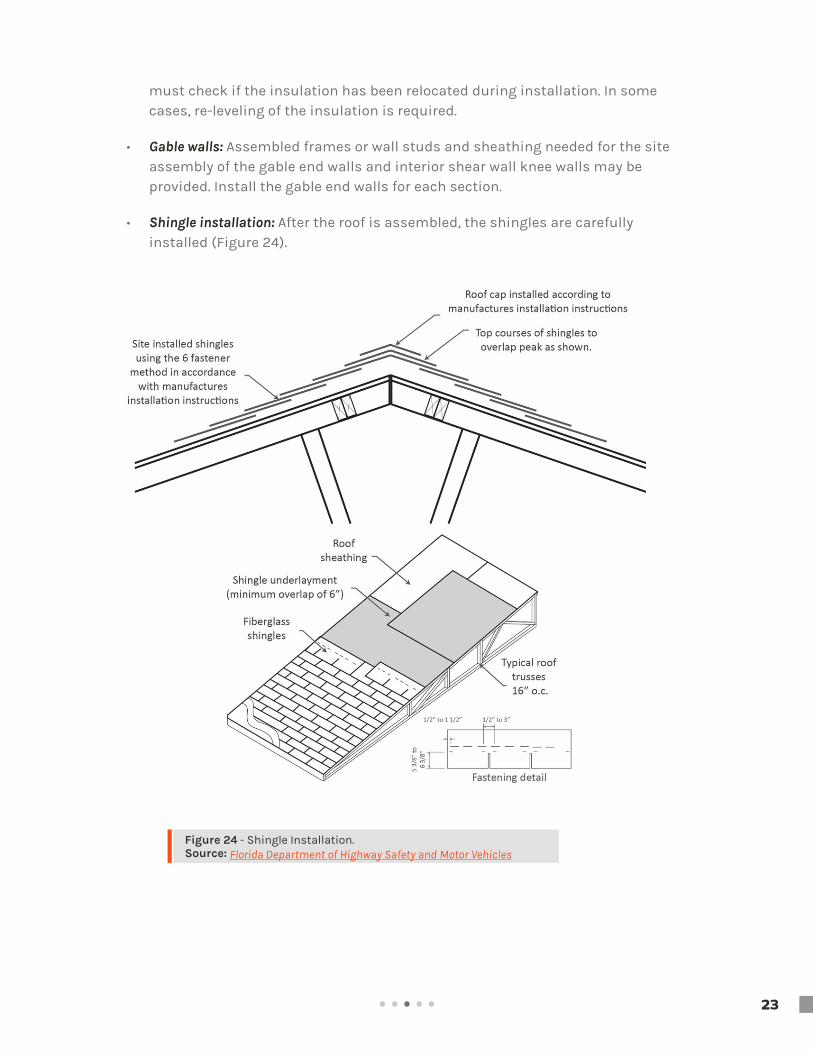
Figure 24 - Shingle Installation.Source: Florida Department of Highway Safety and Motor Vehicles
must check if the insulation has been relocated during installation. In some cases, re-leveling of the insulation is required.
• Gable walls: Assembled frames or wall studs and sheathing needed for the site assembly of the gable end walls and interior shear wall knee walls may be provided. Install the gable end walls for each section.
• Shingle installation: After the roof is assembled, the shingles are carefully installed (Figure 24).
23

. . . . .
review Questions
1. How does site drainage impact manufactured homes? How should the site be prepared to direct water away from the home?
2. Explain the load transfer process to the ground for a manufactured home.
3. What is a pier and what is its function? Explain the differences between single and double stacked piers.
4. What are the three main support locations for piers? Where are other places piers should be located?
4. Explain how manufactured homes are able to resist wind forces.
5. What is a longitudinal stabilization device?
//////////////////////////
24

. . . . .
The installation of utilities is the final step in com-pleting a manufactured home. Each utility should be connected by a qualified professional who has specific expertise and is licensed and trained accord-ingly.
The water supply for the site should be installed before the manufactured home is transported to the site. Typically, governmental agencies provide water supply and sewage connections to every urban area. The factory installed water system is connected to the main water inlet which is usually located under the house in the crawl space area.
The water inlet provided under the home, usually below the water heater compartment or utility room, must be connected to the home’s water system from the water supply (Figure 25). The connection procedure described below must be followed for the proper functioning of the system:
• Flush the field-installed water piping to clean out all debris prior to connec-tions.
• Make sure all the piping inside the house is clean and clear of any interruptions.
• Ensure all pipe threads are clean.
• The local water supply line must not exceed a pressure of 80 psi. If it exceeds this value, a pressure reducing valve must be installed on the supply line.
• The main shut-off valve must be installed while connecting the home’s potable water inlet to the water supply. A shut-off valve must be located underneath or adjacent to the home. To prevent the possibility of fresh water contamination, an anti-siphon valve must be used on all field installed exterior faucets.
• All traps must be provided with proper venting so that there will be no danger of siphonage, aspiration, or forcing traps seals under conditions of ordinary use.
• The sanitary drainage system under the home shall be adequately sup-ported with approved materials and properly sloped to drain. Plastic piping
Water Supply and discharge4.1
Figure 25 - Water line crossover.Source: Florida Department of Highway Safety and Motor Vehicles
field assembly guide for modular and manufacTured homes
utilities4.0
25

. . . . .
shall be supported at not less than four-foot intervals. Drain lines shall be sloped 1/4 inch per foot toward the drain outlet (Figure 26). Where it is impractical, due to structure features or other arrangements, the piping may have a grade of no less than 1/8 inch per foot, when a properly installed full-size cleanout is installed at the upper end. Be sure to use approved materials to assemble the piping material.
All wastewater piping is connected to the sewer outlet that is located under the manu-factured home. Usually, a sewer line is either a 3 inch or 4 inch line connected to a P-trap. The P-trap is cleaned from the top and connected to the sewer line on the ground with another clean out. A Y-connection is made just before the ground sewer line along with a P-trap connection. The Y-connection is connected to a minimum 3 inch trailer vent to release the sewer gasses. Proving vent piping for the wastewater system is manda-tory (Figure 27).
drainage System4.2
Figure 26 - Drain lines must have proper slope under the floor.Source: Florida Department of Highway Safety and Motor Vehicles
Figure 27 - Isometric plumbing example of a typical manufactured home with all connections and pipe dimensions.Source: Florida Department of Highway Safety and Motor Vehicles
A P-trap is a plumbing fixture that traps debris from the sink and prevents it from forming a clog deep within the plumbing system. It also stops sewer gases from passing into the home. A P-trap is mandatory for all manufactured homes.
+
26

. . . . .
Lighting fixtures, ceiling-suspended (paddle) fans, and chain-hung lighting fixtures should be installed in accordance with the manufacturer’s specifications. All the exterior lighting fixtures and ceiling fans must be grounded by a fixture-grounding device or by a fixture-grounding wire (Figure 28). Where lighting fixtures are mounted on combustible surfaces such as hardboard, a limited combus-tible or noncombustible ring must be installed to completely cover the combustible surface exposed between the fixture canopy and the wiring outlet box.
For exterior lights, junction box covers must be removed and wire-to-wire connections must be made. All electrical wires should be color coded and connections must match colors to ensure a correct, hazard free system. The wiring must be pushed and connected to the junction box (Figure 29). A water tight seal must be ensured by caulking around the base of every fixture at the point of contact of the fixture and any surface of the manufactured home. Ceiling-suspended fans must be connected to a junction box listed for ceiling fan application and installed with the trailing edges of the blades at least 6ft. 4 in. above the finished floor. The wiring must be connected in accordance with the product manufacturer’s installation instructions.
After completion of all electrical system and connections, the electrical lights and ceiling fans must be inspected and tested.
The gas piping system in a manufactured home should be designed for a pressure of at least 10 inches of water column [5.8 oz./in2 or 0.36 psi] and not more than 14 inches of water column [8 oz./in2 or 0.5 psi]. A regulator must be installed in case the gas from the supply source exceeds the established pressure. Multi-section homes with fuel supply piping in both sections require crossover connections to join all sections of the home. At the comple-tion of installation, the system must be tested and inspected for leaks and other possible problems.
Figure 28 - Typical electrical ground.Source: Florida Department of Highway Safety and Motor Vehicles
Figure 29 - Electrical wiring connection with junction box. Source: Florida Department of Highway Safety and Motor Vehicles
Electrical4.3
Fuel Supply4.4
27

. . . . .
Fireplace and wood stove assemblies should be installed in accordance with the manu-facturer’s instructions. Chimneys, chimney flashing and roofing, fireplace combustion air inlets, and hearths may be installed during the manufacturing process of the house. However, some additional sections relating to the fireplace and wood stove installation must be installed on site.
The chimney must extend at least three feet above the highest point where it penetrates the roof. It should also be extended at least two feet higher than any surface within 10 feet (Figure 30).
review Questions
1. What measures should be taken into consideration for water services?
2. Explain the use of a P-trap in the drainage system for manufactured homes.
3. How should exterior lights be connected?
4. Explain the fuel supply system for manufactured home.
5. How should chimneys be installed in a manufactured home?
//////////////////////////
Figure 30 - Illustration of minimum chimney height requirement above the surface of the home.Source: Florida Department of Highway Safety and Motor Vehicles
Fire Place4.5
28

. . . . .
The manufactured home final inspection can be made either after the installation of utilities or after the completion of the home. This final inspection is performed by the local authority before delivering the home to the user. The following are typical final inspection procedures for utilities:
Fuel Supply
Before testing, the gas line connections must be visually inspected to ensure that there are no leaks. Specific areas of concern include:
• Ensuring that all exhaust vents on gas-fired equipment are not damaged and are securely connected.
• Ensuring that roof jacks and stacks have not being damaged during trans-portation and are properly installed.
• Ensuring that all gas-fired appliances are suitable for use in manufactured housing and installed accordingly.
If no visible damage is observable, the local authority will test the entire gas system and home appliances. There are two tests that can be used for fuel supply: piping only test or the entire system test.
• Piping Only Test: The piping only test is performed to ensure that there are no minor leaks that could not be detected by visual inspection. This test also ensures that no leaks occur after the pressure is released into the piping system. For the test, all shut-off valves must be placed in closed position. A mercury manometer or slope gauge calibrated in increments of not more than 1/10 lbs is then attached to the home’s gas inlet. Unregulated or exces-sive pressure may result in damage to the appliances. The system is pres-surized up to 3 psi for 10 minutes. This pressure must be maintained in the system. If the system has leaks, the pressure will drop. After all the leaks have been detected, release the pressure and rinse all tested connections with water to remove leak detection fluids. Since repairs to the pipes or fittings are prohibited, replace defective piping and fittings.
field assembly guide for modular and manufacTured homes
Final inspection5.0
29

. . . . .
review Questions
1. When should the final inspection be performed for a manufactured home?
2. Identify the potential locations that should be inspected for fuel leakages during the assembly of manufactured homes.
3. Identify and explain the procedure for fuel supply testing during the final inspection of manufactured homes.
review Questions
1. When should the final inspection be performed for a manufactured home?
2. Identify the potential locations that should be inspected for fuel leaks during the assembly of manufactured homes.
3. Identify and explain the procedure for fuel supply testing during the final inspection of manufactured homes.
//////////////////////////
30

. . . . .Refe
renc
esInstallation guides for relocated manufactured homes by Pennsylvania department of community & economic Development-November 2013 retrieved from http://www.pmha.org/Portals/2/Documents/Installation/InstallationGuideRelocatedManufacturedHomes_2013.pdf
Manufactured Home Installation Manual State of Wisconsin Department of Commerce Division of Safety and Buildings- July 15 2009 retrieved from http://dsps.wi.gov/Documents/Credentialing%20Forms/Manufactured%20Homes%20Application%20Forms/InstallManual1209.pdf
Overview of Manufactured Home Installation MANUFACTURED HOUSING INSTITUTE retrieved from http://www.mhcommunities.org/cm/admin/template/brochures/89temp.pdf
Mobile Home Installation Guide,housing and communit development State of California Business, Transportation and Housing Department of Housing and Community Development January 2007 retrieved from http://www.hcd.ca.gov/codes/mobilehome-special-occupancy-parks/mhiguidebookcomplete1-07.pdf
Model Manufactured Home Installation Standards, Hud –December 7 2016 retrieved from http://www.ecfr.gov/cgibin/retrieveECFR?gp=&SID=1e9980cb67e67f3e5e3660219cfde7ee&mc=true&r=PART&n=pt24.5.3285
Installation manual ,Clayton Homes December 2015 retrieved from https://p.widencdn.net/x8kxrx
Skyline Corporation Manufactured Home Installation Manual- 1/9/2009 retrieved from https://www.dli.mn.gov/ccld/PDF/ms_install_Skyline1209.pdf
Florida Department of Highway Safety and Motor Vehicles. "Installation Course For Manufactured Housing, manu-factured housing sections". Retrieved from http://www.hsmv.state.fl.us/mobilehome/TrngManual.pdf
Manufactured homes, FEMA P-85 chapter 2 retrieved from https://www.fema.gov/media-library-data/20130726-1501-20490-6842/fema_p85_ch2.pdf
Guide to Foundation and Support Systems for Manufactured Homes , retrieved from www.huduser.org
Information Booklet ,Regulation of Mobile/Manufactured Home Manufacturers ,Dealers and Installers Prepared by Manufacturing Housing Section Bureau of Motor Vehicles Field Operations Decision of Motorist Services –Depart-ment of Highway Safety and Motor Vehicles by State of Florida retrieved from http://www.hsmv.state.fl.us/dmv/forms/BMHRV/81094.pdf
Manufactured Installation manual, Palm harbor homes, Inc. September 22, 2008 retrieved from http://www.palmharbor.com/public/phhweb/builders/pdfs/installation_manual_PHH.pdf
Sectional manufactured home installation manual, Friendship homes of Minnesota, retrieved from http://www.dli.mn.gov/ccld/pdf/ms_install_friendshiphomes.pdf
Manufactured Homes and Factory Built Housing Installation Handbook, Colorado Department of Local Affairs Division of Housing Technology and standards, Feb 2014 retrieved from http://lincolncountyco.us/land_use/MHIPHandbook%20(Jan%202016).pdf
Field installation manual manufactured homes (MOD) Multi section homes, Chief custom homes retrieved from https://www.dli.mn.gov/ccld/PDF/ms_install_chief_multi0107.pdf
Manufactured Home Installation Manual for Manufactured Homes Produced On Or After April 1, 2007 by state of Wisconsin retrieved from http://dsps.wi.gov/Documents/Credentialing%20Forms/Manufactured%20Homes%20Application%20Forms/InstallManual1209.pdf
Model Manufactured Home Installation Standards, HUD, retrieved from https://portal.hud.gov/hudportal/documents/huddoc?id=225hud.pdf
Manufactured Home Construction and Safety Standards, 24 CFR Part 3280 retrieved from https://www.law.cornell.edu/cfr/text/24/chapter-XX
HUD homes retrieved from, www.hud.gov/hudhomes
+References
field assembly guide for modular and manufacTured homes
31