field hardware crib notes - lenelkb.lenel.com/al/12/1/1710.pdf · field hardware crib notes...
TRANSCRIPT


Field Hardware Crib Notes
revision 29
This document is maximized for screen resolution and intended for electronic distribution only. To order a printed book, contact Lenel Systems International, Inc.

Lenel OnGuard Field Hardware Crib Notes DOC-602, revision 29, July 2013Copyright © 1997-2013 Lenel Systems International, Inc. Information in this document is subject to change without notice. No part of this document may be reproduced or transmitted in any form or by any means, electronic or mechanical, for any purpose, without the express written permission of Lenel Systems International, Inc.
Non-English versions of Lenel documents are offered as a service to our global audiences. We have attempted to provide an accurate translation of the text, but the official text is the English text, and any differences in the translation are not binding and have no legal effect.
The software described in this document is furnished under a license agreement and may only be used in accordance with the terms of that agreement. Lenel and OnGuard are registered trademarks of Lenel Systems International, Inc.
Microsoft, Windows, Windows Server, and Windows Vista are either registered trademarks or trademarks of Microsoft Corporation in the United States and/or other countries. Other product names mentioned in this User Guide may be trademarks or registered trademarks of their respective companies and are hereby acknowledged.
WarrantyLenel warrants that the product is free from defects in material and workmanship under normal use and service with proper maintenance for one year from the date of factory shipment. Lenel assumes no responsibility for products damaged by improper handling, misuse, neglect, improper installation, over-voltages, repair, alteration, or accident. This warranty is limited to the repair or replacement of the defective unit. In no event shall Lenel Systems International be liable for loss of use or consequential damages of any kind, however occasioned.
There are no expressed warranties other than those set forth herein. Warranty expressly excludes third party additions, deletions and/or upgrades to this product, including those contained herein. Lenel does not make, nor intends, nor does it authorize any agent or representative to make any other warranties or implied warranties, and expressly excludes and disclaims all implied warranties of merchantability or fitness for a particular purpose.
Returned units are repaired or replaced from a stock of reconditioned units. All returns must be accompanied by a return authorization number (RMA) obtained from the Lenel customer service department prior to returning or exchanging any product. The RMA number must appear on the outside of the shipping box and on the packing slip. Any items returned without an RMA number will not be accepted and will be returned at the customer’s expense. All returns must have transportation, insurance, and custom brokers’ fees prepaid.
LiabilityIt is expressly understood and agreed that the interface should only be used to control exits from areas where an alternative method for exit is available. This product is not intended for, nor is rated for operation in life-critical control applications. Lenel Systems International is not liable under any circumstances for loss or damage caused by or partially caused by the misapplication or malfunction of the product. Lenel’s liability does not extend beyond the purchase price of the product.

Table of Contents
Hardware Basics ...................................................................................... 7
Intelligent System Controller LNL-500 ................................................ 23
Intelligent Single Door Controller LNL-2210 ...................................... 31
Intelligent Dual Reader Controller LNL-2220 ...................................... 47
Intelligent System Controller LNL-3300 .............................................. 65
Input Control Module LNL-1100 Series 2 ............................................ 77
Input Control Module LNL-1100-U ..................................................... 89
Output Control Module LNL-1200 Series 2 ....................................... 111
Output Control Module LNL-1200-U ................................................. 121
Single Reader Interface Module LNL-1300 Series 2 .......................... 139
Dual Reader Interface Module LNL-1320 Series 2 ............................ 149
Single Door Controller Module LNL-1300-U .................................... 165
Dual Door Controller Module LNL-1320-U ....................................... 187
Star Multiplexer LNL-8000 ................................................................ 211
LenelProx Readers .............................................................................. 219
v

vi

Basics
Hardware Basics
Power Supplies
MountingMost modules are 6 x 8 inches in size, with mounting holes along the long edge. Up to two (2) units can be
Field hardware power supplies and enclosures
Part # Description
LNL-AL400ULX UL Listed power supply - 12 VDC (4A output, 9.7 - 13.5 VDC, 12 VDC nominal), 120 VAC input, continuous supply current with enclosure, lock, UPS capable (battery optional). Operating temperature: 0° to +49° C (32° to 120° F). Humidity: 0 to 85% RHNC. BTU output: 33 BTU.
LNL-400X-CE220 CE marked power supply - 12 VDC (4A output), 230 VAC input, continuous supply current with enclosure, lock, UPS capable (battery optional). Operating temperature: 0° to +49° C (32° to 120° F). Humidity: 0 to 85% RHNC. BTU output: 33 BTU.
LNL-AL600ULX-4CB6 UL Listed power supply - 12 VDC (6A output, 9.7 - 13.5 VDC, 12 VDC nominal), 120 VAC input, continuous supply current with enclosure, lock, UPS capable (battery optional). Operating temperature: 0° to +49° C (32° to 120° F). Humidity: 0 to 85% RHNC. BTU output: 49 BTU.
LNL-600X6-CE220 CE marked power supply - 12 VDC (6A output), 230 VAC input, continuous supply current with enclosure, lock, UPS capable (battery optional). Operating temperature: 0° to +49° C (32° to 120° F). Humidity: 0 to 85% RHNC. BTU output: 49 BTU.
LNL-CTX Hardware enclosure (12 x 16 x 4.5 inches [304.8 x 406.4 x 114.3 mm]) with lock and tamper switch support up to two Lenel access hardware modules (UL approved).
LNL-CTX-6 Hardware enclosure (18 x 24 x 4.5 inches [457.2 x 609.6 x 114.3 mm]) with lock and tamper switch support up to six Lenel access hardware modules (UL approved).
ABT-12 Battery Kit, 12 VDC, 12AH Battery (PS-12120).
7

Bas
ics
mounted in a single LNL-CTX enclosure. The LNL-CTX-6 allows for up to six (6) modules.Inside view of the LNL-CTX
12.5" 12.5"
15.5
"
OptionalBattery
Power Supply
Pian
o H
inge
HardwareStandoffs
3.00
"2.
00"
2.00
"
HardwareStandoffs
3.00
"2.
00"
2.00
"
0.875"1.25"
1.75
"
1.75
"
5.50"5.50"
Depth
= 4.5
"
8
Basics
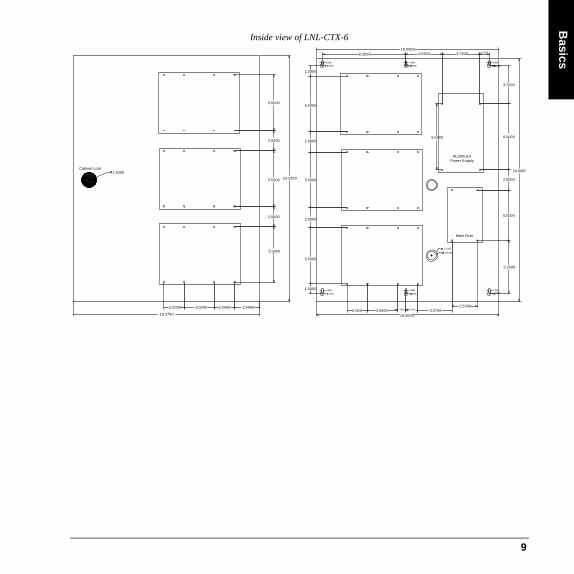
Inside view of LNL-CTX-6
Cabinet Lock1.5000
18.3750
2.0000 2.0000 2.50003.0000
5.5000
2.0000
5.5000 24.2500
2.0000
5.5000
18.00008.2500 3.5625 3.7500 0.9375
0.18690.1869
0.3750
0.1869
0.3750
1.0000
5.5000
2.0000
5.5000
2.0000
5.5000
1.0000 0.1869
0.3750
0.1869
0.3750
2.000 3.000018.0000
3.37502.5000
0.18690.3750
5.2500
5.0000
24.0000
2.0000
1.1250
0.8750
6.5000
3.7500
6.5000
AL600ULXPower Supply
Main Fuse
1.18750.8125
9

Bas
ics
Knockout diagramBackbox Mounting Hole Configuration
0.8125
1.0"
1.50"
3/4" and 1" Knock Outs
5.1875" 4.8125"
0.875"
0.125"
3/4" and 1" Knock Outs
0.375" Clearance Hole0.1875" Slots nominal
10

Basics
LNL-AL400ULX InstallationThe LNL-AL400ULX should be installed in accordance with article 760 of the National Electrical Code and NFPA70 as well as all applicable local codes.
1. Mount the enclosure in desired location.
2. Connect unswitched AC power (120 VAC/60 Hz) to terminals marked L, G, N, dedicated to the Burglar Alarm/Access Control Subsystem.
1/2" and 3/4 knockout locationdrawing
1.5"
1.0"
6.0"
1.0"
11
Bas
ics
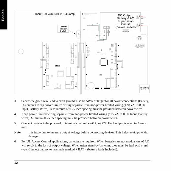
3. Secure the green wire lead to earth ground. Use 18 AWG or larger for all power connections (Battery, DC output). Keep power limited wiring separate from non-power limited wiring (120 VAC/60 Hz Input, Battery Wires). A minimum of 0.25 inch spacing must be provided between power wires.
4. Keep power limited wiring separate from non-power limited wiring (115 VAC/60 Hz Input, Battery wires). Minimum 0.25 inch spacing must be provided between power wires.
5. Connect devices to be powered to terminals marked -out1+; -out2+. Each output is rated to 2 amps max.
Note: It is important to measure output voltage before connecting devices. This helps avoid potential damage.
6. For UL Access Control applications, batteries are required. When batteries are not used, a loss of AC will result in the loss of output voltage. When using stand-by batteries, they must be lead acid or gel type. Connect battery to terminals marked + BAT – (battery leads included).
Input 120 VAC, 60 Hz, 1.45 amp.
blue
gree
n
brow
n
DC Output,Battery & ACSupervision
Circuit(power limited)
To Batteryin CTX
+ INPUT ---
+ OUT2--- + OUT1---
12

Basics
7. Connect appropriate trouble reporting devices to AC Fail and Low Battery supervisory relay outputs marked NC, C, NO. Use 22 AWG to 18 AWG for AC Fail and Low Battery reporting. AC Failure will will report in 2 minutes; 2 hours if jumper is cut. For a six-hour delay on reporting, cut resistor R1.
8. Wire routing note: UL two panel installation instructions for LNL-CTX enclosures
To install multiple Lenel hardware panels into a single enclosure, the following guidelines must be used for certified UL installations.
• All wire connections that cross over the hinge side of the door must be wire wrapped or tie wrapped together.
• All wire must be routed behind the hardware panel so that the wires are secure from movement when opening and closing the door.
• All connections for the lock side of the enclosure must come from behind the Lenel hardware devices.
LNL-AL600ULX-4CB6 InstallationThe LNL-AL600ULX-4CB6 should be installed in accordance with article 760 of the National Electrical Code of NFPA70 as we as all applicable local codes. If you are located in Canada, refer to the Canadian Electrical Code.
1. Mount the enclosure in desired location.
2. The power supply is pre-wired to the ground (chassis). Connect main incoming ground to the provided green grounding conductor lead. Connect unswitched AC circuit (115 VAC/60 Hz) dedicated to the Burglar Alarm/Access Control Subsystem to terminals marked L, G, N.
13

Bas
ics
3. Keep power limited wiring separate from non-power limited wiring (115 VAC/60 Hz Input, Battery wires). Minimum 0.25 inch spacing must be provided between power wires.
4. Connect devices to be powered to terminals marked (1P-1N, 2P-2N, 3P-3N, 4P-4N) and distribute evenly. Each output is rated at 1.5 amps max.
Note: It is important to measure output voltage before connecting devices. This helps avoid potential damage. Use 18 AWG or larger wire for all power connections (battery, DC outputs).
For UL Access Control applications, batteries are required. When batteries are not used, a loss of AC will result in the loss of output voltage. When the use of stand-by batteries is desired, they must be lead acid or gel type. Connect battery to terminals marked + BAT – (battery leads included).
LENEL Hardware
LENEL Hardware
LENEL Hardware
LENEL Hardware
AL1012U
LXB
L G N
bla
ck
red
bla
ck
red
Input 115 VAC, 60Hz, 1.9 amp.
To Battery in LNL-CTX
Main Fuse
1P, 2P, 3P, and 4P = Fused Outputs
F1
F2
F3
F4
ON - OFF
+ BAT --
AC
FAIL
BA
TFA
ILN
C C
NO
NC
C N
O
+ DC --
--+
4 4
P N
3 3
P N
2 2
P N
1 1
P N
InputPD4A
1N, 2N, 3N, and 4N = Common Outputs
Output Circuit 1
Output Circuit 2
Output Circuit 3
Output Circuit 4
Neutral - WhiteGround - Green
Hot - Black
white
green
black
Ca
bin
et T
am
pe
r Sw
itch
Power Limited Devices
LEN
EL
Hardw
are
LEN
EL
Hardw
are
LNL-AL600ULX-4CB6Enclosure Dimensions:24"H x 18"W x 4.5"DUnit includes Cabinet, Cabinet Tamper Switch, Power Supply, Power Distribution Circuit, Battery Leads, Lenel access hardware mounts/screws, and Lock.
CAUTION:De-energize unit prior to servicing. So not expose to rain or moisture.
Battery & AC Supervision Circuit (power limited)
14
Basics
5. Connect appropriate trouble reporting device to the Battery Fail and AC Fail supervisory relay outputs marked NC, C, NO. Use 22 AWG or 18 AWG for AC Fail/Battery Fail reporting. AC Failure will report in 2 minutes; 2 hours if jumper is cut. For a six-hour delay on reporting, cut resistor RL1.
6. Connect cabinet tamper switch to cabinet tamper circuit on the Lenel access hardware.
7. Wire routing note: UL six panel installation instructions for LNL-CTX enclosures
To install multiple Lenel hardware panels into a single enclosure, the following guidelines must be used for certified UL installations.
• All wire connections that cross over the hinged side of the door must be wire wrapped or tie wrapped together.
• All wire must be routed behind the hardware panels so that the wires are secured from movement when opening and closing the door.
• All connections from the lock side of the enclosure must come from the Lenel hardware devices.
RS-485 Communication WiringProper wiring for RS-485 communication interfaces is critical for successful system turn-up and operation. The following guidelines apply for all RS-485 wiring.
1. Use low capacitance shielded cable with 2 twisted pairs, characteristic impedance 120 ohms (Belden9842 or equivalent) for the main RS-485 run.
2. Keep the main run maximum end-to-end distance below 4000 feet.
3. Use daisy chain configuration, NOT star configuration, to connect devices.
4. Use shielded 24 AWG cable with 2 twisted pair (Belden 9502 or equivalent) for down leads (drops or stubs).
5. Keep down leads as short as possible (no longer than 10 feet).
15

Bas
ics
6. Terminate cables at both ends with RS-485 terminators (hardware has on-board terminators for RS-485 termination).
7. Always use the signal ground (SG) connection. Carefully insulate the SG wire for a reliable installation. Use 24 GA plastic sleeving over the SG wire when terminating the cable to the 5-position insulation displacement mating connector.
Each RS-485 communication line can have any number of DEPENDENT devices, but must have only one MASTER device. The transmit lines of the MASTER device are connected to the receive lines of the DEPENDENT devices and the receive lines of the MASTER device are connected to the transmit lines of the DEPENDENT devices. Observe the + and the - of each pair (NOTE: only applies to 4-wire RS-485 wiring).
KEEP DOWN LEAD SHORT(10 FEET MAX.)
TO NEXT UNITOR TERMINATOR
TO PREVIOUS UNITOR TERMINATOR
RS-485 CABLE, 100 Ohm IMPEDANCEBELDEN 9842 OR EQUIVALENT
Reader Interface Module
16

Basics
Refer to the following diagrams for RS-485 Signal Ground and Termination.
RS-485 Multi-drop Wiring and EOL Termination
ISC
T+ T- SG
Earth Ground, one point only
per ISC
Shield
PV
C C
ove
r W
ire
PV
C C
ove
r W
ire
PV
C C
ove
r W
ire
/or
Dra
in
Wire
T+ T- SG
Dual Reader Interface
T+ T- SG
Biometric Reader Gateway
T+ T- SG
T+ T- SG
Dual Reader Interface
T
T
T = On Board Termination
T+ T- SGBiometric Reader
T+ T- SGBiometric Reader
T+ T- SGBiometric Reader
T
Enclosure Ground Enclosure Ground Enclosure Ground
Downstream ports 2 & 3 typical
17

Bas
ics
T+ T- SGBiometric Reader
T+ T- SGBiometric Reader
T+ T- SGBiometric Reader
ISC
T+ T- SG
Earth Ground, one point only per ISC
Shield
PV
C C
ove
r W
ire
PV
C C
ove
r W
ire
PV
C C
ove
r W
ire/o
r D
rain
W
ire
T+ T- SG
Dual Reader Interface
T+ T- SG
Biometric Reader Gateway
T+ T- SG
T+ T- SG
Dual Reader Interface
T T
T = On Board Termination
Enclosure Ground Enclosure Ground Enclosure Ground
RS-485 Multi-drop Wiring and EOL TerminationISC and Biometric Gateway Mid RS-485
= Indicates RS-485 in and out or less than 10 foot drop
Downstream ports 2 & 3 typical
18
Basics
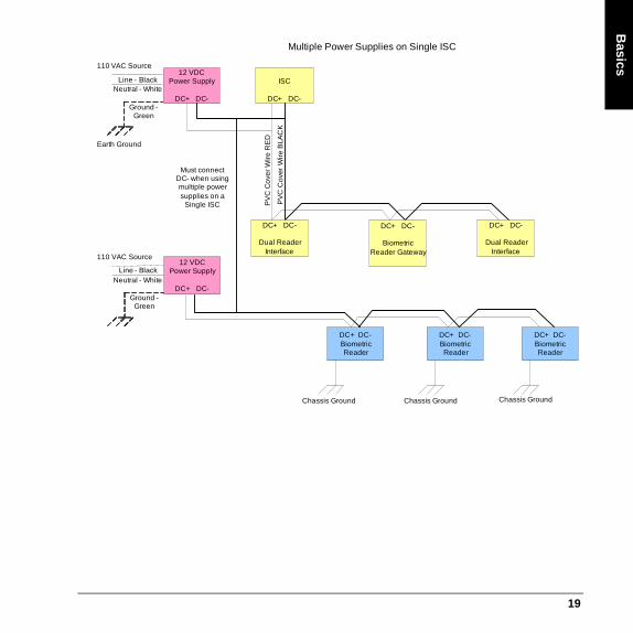
Multiple Power Supplies on Single ISC
ISC
DC+ DC-
Earth Ground
PV
C C
ove
r W
ire
RE
D
PV
C C
ove
r W
ire
BLA
CK
DC+ DC-
Dual Reader Interface
DC+ DC-
Biometric Reader Gateway
DC+ DC-
Dual Reader Interface
DC+ DC-Biometric Reader
DC+ DC-Biometric Reader
DC+ DC-Biometric Reader
Chassis Ground Chassis Ground Chassis Ground
12 VDC Power Supply
DC+ DC-Ground -
Green
Line - BlackNeutral - White
110 VAC Source
12 VDC Power Supply
DC+ DC-Ground -
Green
Line - BlackNeutral - White
110 VAC Source
Must connect DC- when using multiple power supplies on a
Single ISC
19

Bas
ics
Relay Contact ProtectionDC Inductive LoadContacts for DC inductive loads can be effectively protected using clamp diodes. Select diodes with reverse breakdown voltage 10 times the circuit voltage.
AC Inductive LoadContacts for AC inductive loads can be protected using metal-oxide varistors (MOVs). MOVs are effective when the load voltage is 100 V to 200 V. (MOVs are also suitable for DC operation).
MOVs must be installed as close to the load as possible (within a few inches) to be effective. Mounted in this fashion, MOVs can also reduce the effects of EMI on sensitive electronic circuits.
System Turn-Up Considerations1. Make sure that no power is applied to any device.
2. Check all wiring and device switch settings.
3. Disconnect all devices from the RS-485 communication line.
4. Power up the controller. Be sure to check voltage requirement first.
5. Configure the controller and verify that it is working properly.
DC SOURCE
AC SOURCE
NC
C
NO
NC
C
NO
FUSE
+
-
LOAD
LOAD
MOV
FUSE
20

Basics
6. Connect one port of the RS-485 communication line to the multiplexer.
7. Power up a DEPENDENT device, and verify that it passes its own power-up self-test. Again, be sure to check voltage requirement first.
8. Check for ground fault between the DEPENDENT device and the RS-485 communication line. If applicable, find the fault and clear it.
9. Connect the DEPENDENT device to the RS-485 line and bring it on-line.
10. Verify all functions of the DEPENDENT device.
11. Verify the RS-485 line voltage in reference to the signal ground.
12. For each additional DEPENDENT device, repeat steps 7 through 11.
13. Verify the RS-485 line voltage for the controller, and mark the readings on the inside of the controller panel for future reference.
Device Configuration ChecksSystem programming must include the order of priority signals described below:
1. Hold-up or panic alarm or duress.
2. Burglar alarm.
3. Burglar alarm supervision.
4. Industrial supervision where a risk of injury to persons, or damage or destruction of property will not be involved.
5. Other supervisory services.
Items (1) and (2) may have equal priority. Items (4) and (5) may have equal priority.
Ground Potential Difference ChecksTo check if there is ground fault for a new unit,
1. Apply power to all devices already successfully connected to the RS-485 line.
2. Power up the new unit, but DO NOT connect it to the RS-485 line.
3. Connect the signal ground (SG) of the RS-485 line through a 10K limiting resistor.
4. Measure the AC and DC voltage across the resistor. There should NOT be more than one volt across the resistor. Otherwise, find and clear the fault.
5. Connect the new unit to the RS-485 line if no ground fault is found.
21

Bas
ics
22

LN
L-500
Intelligent System Controller LNL-500The Intelligent System Controller (ISC) interfaces upstream with the access control software on the host system. It provides real time processing for the I/O interfaces to which it is connected. Multiple combinations of Input Control Modules, Output Control Modules, and Reader Interface Modules can be connected. The ISC can have two downstream 2-wire RS-485 channels or one 4-wire RS-485 channels. In either configuration, you may connect up to 32 readers or 16 devices on a single ISC.
LNL-500 Components
B
ACDC
AC
GND
GND
GND
IN2
IN1
J4 J7
23
24
85
2W
4
W
TXDTR1+
RXDTR1-
RTSR1+
CTSR1-
GND
TR2+
TR2-
GND
TR3+
TR3-
GND
J11
J12
S1
U4
Lithium Ion3V BR2325
8 7 6 5 4 3 2 1
485 232
J3
J5
J6
J9
A
C
2.0
0 (
50
.8)
2.0
0 (
50
.8)
.50 (12.7)
5.50 (139.7)
6.00 (152.4)
DIP SWITCHES
PROGRAM PROM
J8
J10
J13
.50 (12.7)
FOR ETHERNET APPLICATION:LANTRONIX COBOX MICRORICHCO PLASTICS STANDOFF
23

LN
L- 5
00
Alarm InputsIf either of these inputs is not used, install a shorting wire.
Unsupervised Alarm Input Wiring
Upstream Host CommunicationThe ISC uses Port 1 to communicate to the host system. Port 1 can be wired as an RS-232 interface for direct one-to-one (or modem) communication, or as an RS-485 interface for multi-drop or extended distance communication. If RS-485 communication is used, an RS-232 to RS-485 converter is required at the host workstation.
Upstream Host Communication Wiring (Port 1)
Port 1 - wiring configuration. This configuration will work for direct connect (RS-232) and Lantronix Ethernet network communications.
GND
IN 2
GND
IN 1
CABINETTAMPER
POWERFAULT
PORT 1, CONFIGURED AS RS-232
Wire with 24 AWG.
TR1+
TR1-
GND
R1 -
R1 +
4-WIRE SG TR - TR+ R- R+
PORT 1, CONFIGURED AS RS-485Wire with 24 AWG stranded twisted pair(s) with shield.
TERMINATE RS-485 END OF BUS
TXD/TR1+
RXD/TR1-
GND
CTS/R1 -
RTS/R1 +
TXD/TR1+
RXD/TR1-
GND
CTS/R1 -
RTS/R1 +
2-WIRE Earth Ground
Earth Ground
24

LN
L-500
With direct connect DIP switch 5 needs to be OFF and with Lantronix 5 needs to be ON.
Downstream Device CommunicationThe ISC can be configured to communicate downstream with up to 8 input/output devices, using Port 2 and Port 3. Each of these ports can be wired only as an RS-485 interface, for multi-drop communication on a single bus of up to 4000 feet.
For Ports 2-3, the following type of RS-485 cable is required: 24 AWG (minimum) twisted pair (with shields.) Either 2-wire or 4-wire RS-485 cable configuration can be used. The main run RS-485 cable should be no longer than 4000 feet (1219 m), 100 ohms maximum (Belden 9842 4-wire or 9841 2-wire,
ISC 9-pin connector 25-pin connector
TXD/TR1+ pin 2 pin 3
RXD/TR1- pin 3 pin 2
RTS/R1+ not used not used
CTS/R1- pin 7 pin 4
GND pin 5 pin 7
Jumper together 4, 6 & 8 5, 6 & 20
25

LN
L- 5
00
plenum cabling Belden 88102 or equivalent). The drop cables (to readers and other devices) should be kept as short as possible, no longer than 10 feet.
PowerThe ISC accepts either a 12 VDC or 12 VAC ± 15% power source for its power input. If using a 12 VDC power source, be sure to observe polarity. The power source should be located as close to the ISC as possible. Wire the power input with 18 AWG (minimum) twisted pair cable.
Power Source Wiring
TR2 +
TR2 -
GND
TR3 +
TR3 -
GND
2-WIRE
TR2 +
TR2 -
GND
TR3 +
TR3 -
GND
GND TR- TR+ R- R+
Downstream Device
4-WIRE
GND T- T+
Ports 2 - 3RS-485
Earth Ground
ACDC
AC
GND
ACDC
AC
GND
12 V12 VAC
12 V
+
–
12 VDC
... OR ...
26

LN
L-500
DIP SwitchesDIP switches must be configured appropriately for your system.
Processor Address
Address DIP SWITCH
1: 2: 3: 4:
0 (default) off off off off
1 ON off off off
2 off ON off off
3 ON ON off off
4 off off ON off
5 ON off ON off
6 off ON ON off
7 ON ON ON off
Communication Handshake Status
HANDSHAKE STATUS DIP SWITCH 5:
Transmit enable by CTS ON
None off
27

LN
L- 5
00
DIP switch 8 controls the utilization of encryption. The ISC supports encryption with use of AES firmware. The controller must have a 256 KB chip.
The controller only reads DIP switch settings when it is powered up. If DIP switch settings are changed, the controller must go through a power cycle before the changes are seen.
Installing JumpersThe jumpers must be configured appropriately for your system.
Communication Baud Rate
BAUD RATE DIP SWITCH
6: 7:
38400 bps ON ON
19200 bps off ON
9600 bps ON off
Communication Password Status
PASSWORD STATUS DIP SWITCH 8:
Encryption is optional off
Encryption is required ON
28

LN
L-500
[J13]OFF: Port 1, Ethernet (Cobox-micro)ON: Port 1, serial (RS-232/RS-485)
B
ACDC
AC
GND
GND
GND
IN2
IN1
J4 J7
232
48
5
2W
4W
TXDTR1+
RXDTR1-
RTSR1+
CTSR1-
GND
TR2+
TR2-
GND
TR3+
TR3-
GND
J11
J12
S1
U4
Lithium Ion3V BR2325
8 7 6 5 4 3 2 1
485 232
J3
J5
J6
J9
A
C
J8
J10
J13
[J12]OFF: Port 3 RS-485 EOL termination is not onON: Port 3 RS-485 EOL termination is on
[J4]Control for Port 1, RS-232 or RS-485[J7]Control for Port 1, 2-wire or 4-wire
[J11]OFF: Port 2 RS-485 EOLtermination is not onON: Port 2 RS-485 EOLtermination is on
[J8, J10]OFF: Port 1 RS-485 EOLtermination is not onON: Port 1 RS-485 EOLtermination is on
[J3, J5, J6, J9]Control for Port 1, RS-232or RS-485
29

LN
L- 5
00
SpecificationsThe LNL-500 is for use in low voltage, class 2 circuits only. These specifications are subject to change without notice.
• Primary power: (DC or AC)
- DC input: 12 VDC + 10%, 250 mA- AC input: 12 VAC + 15%, 400 mA RMS
• Memory and clock backup: 3 volt Lithium (Rayovac BR2325 or Wuhan Lixing CR2330)
• Communication ports:
- Port 1: RS-232 or RS-485 (2-wire or 4-wire), 9600 to 38400 bps async- Port 2-3: RS-485 (2-wire), 9600 to 38400 bps async
• Inputs:
- Cabinet Tamper Monitor: unsupervised, dedicated- Power Fault Monitor: unsupervised, dedicated
• Wire requirement:
- Power: 1 stranded twisted pair, 18 AWG- RS-485: 24 AWG stranded twisted pair(s) with shield, 4000 feet (1219 m) max.- RS-232: 24 AWG stranded, 50 feet (15.24 m) maximum- Inputs: 1 stranded twisted pair, 30 ohms maximum
• Environmental:
- Temperature: 32 to 158° F(0 to 70° C) operating, -67 to +185° F (-55 to +85° C) storage- Humidity: 0 to 95% RHNC
• Mechanical:
- Dimensions: 6 x 5 x 1 in. (152 x 127 x 25 mm)- Weight: 8 oz. (227 g) nominal
• Data memory: 512 KB
• Certifications:
- UL294 and UL1076 Listed, ULC Listed- FCC Part 15- C-Tick- FIPS 197 Certificate #305- CE marking- RoHS compliant- WEEE
30

LN
L-2210
Intelligent Single Door Controller LNL-2210This controller provides a single door solution with either a single reader or two readers for ingress/egress operation. The board contains the following components: one (1) host Ethernet interface, one (1) power-in input, two (2) unsupervised/supervised inputs, two (2) reader interfaces, two (2) output relays, four (4) DIP switches, seven (7) jumpers, seven (7) status LEDs, and one (1) reset switch.
LNL-2210 Board
TB1 TB2 TB31 1 1
12V
PoE
J3
TB51
TB41
34
S1
2 1
ON
S2
7 6 5 4 3 2 1
J7
J1
J4
J5
BT1
K1
J6
K2
TB1
TB5
RESET SWITCH
2.55 [64.77] 2.55 [64.77] .15 [3.81].20 [5.08]
5.40 [137.16]
2.35
[59.
69]
.20 [5.08]
2.75
[69.
85]
TAMPER SWITCHCONNECTION(J7)
ETHERNETCONNECTOR(J6)
PoE/12VDCPOWER SELECTORJUMPER (J3)
DIP SWITCHES STATUS LEDs
31

LN
L-2
210
Wiring and SetupRefer to the following table for wiring and setup of the LNL-2210.
Connections
TB1-1 IN1IN1
Input 1
TB1-2
TB1-3 IN2IN2
Input 2
TB1-4
TB2-1 VO Reader 1 Power Output – 12VDC
TB2-2 LED Reader 1 LED Output
TB2-3 BZR Reader 1 Buzzer Output
TB2-4 CLK Reader 1 CLK/Data 1/TR+
TB2-5 DAT Reader 1 DAT/Data 0/TR-
TB2-6 GND Reader 1 Ground
TB3-1 LED Reader 2 LED Output
TB3-2 BZR Reader 2 Buzzer Output
TB3-3 CLK Reader 2 CLK/Data 1/TR+
TB3-4 DAT Reader 2 DAT/Data 0/TR–
TB4-1 VO Auxiliary Power Output – 12VDC
TB4-2 GND Auxiliary Power Output Ground
TB4-3 VIN Input Power – 12VDC (from local power supply)
TB4-4 GND Input Power Ground
32

LN
L-2210
Communication WiringThe controller communicates to the host via the onboard 10-BaseT/100Base-TX Ethernet interface (port 0).
Reader WiringThe first reader port supports readers that utilize D1/D0, Clock/Data, or OSDP 2-wire RS-485 electrical signaling. The second reader port supports readers that utilize D1/D0, Clock/Data. Power to the first reader is 12VDC and is current limited to 150mA. The second reader may be powered from the auxiliary power output on TB4-1 and TB4-2. Readers that require different voltage or have high current requirements should be powered separately. Refer to the reader manufacturer specifications for cabling requirements. In the 2-wire LED mode, the Buzzer output is used to drive the second LED. Reader port configuration is set via the host software.
TB5-1 NO Relay K1 – Normally Open Contact
TB5-2 1-C Relay K1 – Common Contact
TB5-3 NC Relay K1 – Normally Closed Contact
TB5-4 NO Relay K2 – Normally Open Contact
TB5-5 2-C Relay K2 – Common Contact
TB5-6 NC Relay K2 – Normally Closed Contact
Connections (Continued)
33

LN
L-2
210
Reader wiring
R E D (1 )
W H T (3)G R N (2 )
BR N (4)
B LK (6)
O R G (5 )
V OLEDB ZR
C LK/D 1D AT/D 0G N D
1T
B2
FIR ST R E AD E R P O R TD AT A1/D AT A0 O R C LO C K/D AT A
VO (12VDC)
TB2BZR
CLK/D1DAT/D0
GND
LED
1
GE
NE
RIC
CA
RD
RE
AD
ER
RED (1)
BRN (4)ORG (5)
GRN (2)
BLK (6)
WHT (3)
1BZR
DAT/D0CLK/D1
LED
SECOND READER PORTDATA1/DATA0 OR CLOCK/DATA
1TB
4
GNDVIN
GND
VO
FIRST READER PORT
TB3
34

LN
L-2210
Input Circuit WiringTypically, these inputs are used to monitor door position, request to exit, or alarm contacts. Input circuits can be configured as unsupervised or supervised. When unsupervised, reporting consists of only the open or closed states.
When configured as supervised, the input circuit will report not only open and closed, but also open circuit, shorted, grounded*, and foreign voltage*. A supervised input circuit requires two resistors be added to the circuit to facilitate proper reporting. The standard supervised circuit requires 1K Ohm, 1% resistors and should be located as close to the sensor as possible. Custom end of line (EOL) resistances may be configured via the host software.
* Grounded and foreign voltage states are not a requirement of UL 294 and therefore not verified by UL.
The input circuit wiring configurations shown are supported but may not be typical:
Relay Circuit WiringTwo relays are provided for controlling door lock mechanisms or alarm signaling. The relay contacts are rated at 2A @ 30 VDC, dry contact configuration. Each relay has a Common pole (C), a Normally Open pole (NO) and a Normally Closed pole (NC). When you are controlling the delivery of power to the door strike, the Normally Open and Common poles are used. When you are momentarily removing power to unlock the door, as with a mag lock, the Normally Closed and Common poles are used. Check with local building codes for proper egress door installation.
1K,1%
1K,1%
1K,1%
1K,1%
Standard Supervised Circuit,Normally Closed Contact
Standard Supervised Circuit,Normally Open Contact
Unsupervised Circuit,Normally Open Contact
Unsupervised Circuit,Normally Closed Contact
IN2
IN1
TB11 }
35

LN
L-2
210
Inductive door locking devices may induce relay contact arcing as the contact opens that can cause damage and premature failure of the relay. For this reason, it is recommended that either a diode or MOV (metal oxide varistor) be used to protect the relay. Wire should be of sufficient gauge to avoid voltage loss.
• Diode Selection: Diode current rating: 1x strike current. Diode breakdown voltage 4x strike voltage. For 12 VDC or 24 VDC strike, diode 1N4002 (100V/1A) typical.
• MOV Selection: Clamp voltage: 1.5x VAC RMS. For 24 VAC strike, Panasonic ERZ-C07DK470 typical.
+-
TB5
2-C
NC
NC
NO
1
NO
1-C
DC STRIKE
DIODE
FUSE
12 VDCPOWER SUPPLY
TB51
NO
1-CNC
NC
NO
2-C
AC STRIKE
MOV
FUSE
ACTRANSFORMER
36
LN
L-2210
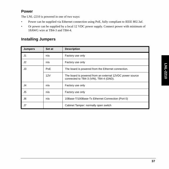
PowerThe LNL-2210 is powered in one of two ways:
• Power can be supplied via Ethernet connection using PoE, fully compliant to IEEE 802.3af.
• Or power can be supplied by a local 12 VDC power supply. Connect power with minimum of 18AWG wire at TB4-3 and TB4-4.
Installing Jumpers
Jumpers Set at Description
J1 n/a Factory use only
J2 n/a Factory use only
J3 PoE The board is powered from the Ethernet connection.
12V The board is powered from an external 12VDC power source connected to TB4-3 (VIN), TB4-4 (GND).
J4 n/a Factory use only
J5 n/a Factory use only
J6 n/a 10Base-T/100Base-Tx Ethernet Connection (Port 0)
J7 Cabinet Tamper: normally open switch
37

LN
L-2
210
Setting Dip SwitchesThe switches on S1 DIP switch configure the operating mode of the processor. DIP switches are read on power-up except where noted. Pressing switch S2 causes the board to reset.
Configuration via Web PageThe Configuration Web Page can be launched from within System Administration (only if an IP address or host name is specified) or by using a browser to access the programmed IP address. Depending on your proxy settings, you may have to allow this web page. (For more information, consult your browser’s documentation or system administrator for assistance.)
Switch Selection:
SW1 When SW1 is on, use the default login user name and password. (This can be changed without resetting the board.)User name: adminPassword: password
SW2 During power up, when SW2 is on (and SW1 is off) for the first 10 seconds, the static IP address is 192.168.0.251, and the primary path is configured for IP Server.
SW3 By default this switch is off and SSL is enabled. Turn SW3 ON to disable SSL settings.
SW4 Not used.
38

LN
L-2210
1. In System Administration in the Access Panels folder, click [Configuration Web Page]. This page will launch in a browser. (You may also access this page by going to the device IP address from within the browser.)
2. Click the link to go to the login page. Log in using your user name and password. If DIP switch 1 is ON, then the default user name and password is used (admin, password). If DIP switch 1 is off, use the login that was programmed in the device. Click [Login].
3. The Home page indicates the type of device and has a Notes field. You may type in a description here. Click [Save Notes].
4. To configure network settings, click [Network].
• If you are using DHCP, specify a host name. By default, the host name consists of “MAC” followed by the numbers of the device MAC address. With DHCP, IP settings will be configured automatically.
• For a static IP address, specify the IP address, subnet mask, and default gateway.
• Click [Accept].
5. To configure the host, click [Host Comm].
a. Specify the controller’s communication address.
b. Configure the following under Primary Host Port:
– Connection Type: IP Server.
– Data Security: The controller is capable of Password/AES encryption.
– Port Number (default 3001) Must match setting in the access control software.
When using an IP Server connection, the controller may be configured to allow all IP addresses or only authorized IP addresses.
c. Click [Accept].
6. To view information, click [Device Info].
You may view the time and product ID, as well as properties that have been configured, such as firmware version, serial number, device name, DIP switches, etc.
7. For users configuration, click [Users].
User accounts may be created, edited or deleted. Each user account has an associated user name and password, as well as a level and notes.
a. One of three different levels may be assigned to users.
39

LN
L-2
210
– Level 1 — Full control
– Levels 2 and 3 have the following permissions:
For pages that cannot be viewed, the message is displayed when users attempt to access the page: “This page is unavailable due to one of the following reasons: your user level is not authorized to view this page, or another level 1 user is logged in at this time.”
b. Select the password strength.
– Low - The minimum password length must be six characters. None of the password strength criteria will be enforced.
– Medium - The minimum password length must be six characters. Two of the password strength criteria must be met.
Access View allowed Edit allowed
Home page Level 2: Yes (cannot edit notes)Level 3: Yes (cannot edit notes)
Level 2: NoLevel 3: No
Network page Level 2: YesLevel 3: No
Level 2: NoLevel 3: No
Host Port page Level 2: YesLevel 3: No
Level 2: NoLevel 3: No
Device Info page Level 2: YesLevel 3: Yes
n/a
Users page Level 2: NoLevel 3: No
Level 2: NoLevel 3: No
Restore/Default page Level 2: NoLevel 3: No
Level 2: NoLevel 3: No
Apply Setting page Level 2: NoLevel 3: No
Level 2: NoLevel 3: No
40

LN
L-2210
– High - The minimum password length is eight characters. Three of the password strength criteria must be met. Additionally, strong passwords are checked to make sure that they are not based on the user name.
Password strength criteria:
– Uppercase alphabet characters
– Lowercase alphabet characters
– Arabic numerals (0-9)
– Non alphanumeric characters ` ! ? $ ^ * ( ) _ - + = { [ } ] : ; @ ~ # | < , > . ? /
Characters " , \, &, = and % are invalid characters and cannot be used for passwords.
c. Specify the Session Timer (5 to 60 minutes). Click [Save].
d. You may disable the web server by selecting the check box. When this option is selected and SW1 is off, all ports except for the host communication port will be disabled. The configuration web page cannot be used to access the device.
e. Select the Enable door forced open filter check box if you do not want a forced open alarm generated if the door is opened within three seconds of it being closed.
8. For configuration of auto-save, click [Auto-Save].
a. On this page, you may restore the last save or clear all the settings.
b. Choose to disable or enable Auto-Save. If Auto-Save is enabled, volatile memory is written to flash. The frequency of this action is specified in the timer (30 seconds to 30 minutes). Click [Save Settings].
9. You may click [Restore/Default] if you need to reload the factory settings or the current operating settings.
10. When you have completed configuring the device, click [Apply Settings], [Apply Settings, Reboot], and then [Log Out].
Additional Mounting InformationSources for the optional items shown below:
• 3-gang stainless steel blank cover: Leviton part number 84033-40. Available from Graybar, part number 88158404
• Magnetic switch set: G.R.I. part number: 505
41

LN
L-2
210
Side view
FIELD WIRING
2210 WITH INCLUDEDMOUNTING PLATE
TO ETHERNETNETWORK
3-GANGJUNCTION BOX
BLANKCOVER W/SCREWS
MAGNETICTAMPER SWITCH
42

LN
L-2210
Mounting plate dimensions
Status LEDsPower-up: All LEDs OFF.
Initialization: LEDs 1, 2, 3, 4, 5, 6, and 7 are sequenced during initialization. LEDs 1, 3, and 4 are turned ON for approximately four seconds after the hardware initialization has completed, then the application code is initialized. The amount of time the application takes to initialize depends on the size of the database, about 3 seconds without a card database. Each 10,000 cards will add about 3 seconds to the application initialization. When LEDs 1, 2, 3 and 4 flash at the same time, data is being read from or written to flash memory, do not cycle power when in this state. If the sequence stops or repeats, perform the Bulk Erase Configuration Memory procedure. If clearing the memory does not correct the initialization problem, contact technical support.
3.85 [97.8]
2.35 [59.7]
5.50 [139.7]
3.63 [92.1]
3.30 [83.8]
3.63 [92.1]
Ø0.16 [Ø4.0]1300 MGT HOLES
4PL
Ø0.16 [Ø4.0]3-GANG MGT HOLES
4PL
43

LN
L-2
210
Running: After initialization is complete, the LEDs have the following meanings: At power up, LEDs 2 through 7 are turned ON then OFF in sequence.
LED Description
1 Off-line/On-line and battery status
Off-line = 20% ON, On-line = 80% ON
Double flash if battery is low
2 Host communication activity
3 Readers (Combined) Reader 1: Clock/Data or D1/D0 Mode = Flashes when Data is Received, Either Input. RS-485 Mode = Flashes when Transmitting Data
4 Input IN1 Status: OFF = Inactive, ON = Active, Flash = Trouble
5 Input IN2 Status: OFF = Inactive, ON = Active, Flash = Trouble
6 Cabinet tamper
7 Not used
YEL Ethernet Speed: Off = 10Mb/S, ON = 100Mb/S
GRN Off = no link, ON = good link, Flashing = Ethernet activity
44

LN
L-2210
SpecificationsThe interface is for use in low voltage, class 2 circuits only, and it is for use with UL Listed access control power limited power supplies. The installation of this device must comply with all local fire and electrical codes. These specifications are subject to change without notice.
• Power Input:
- PoE power input 12.95 W, compliant to IEEE 802.3af or- 12 VDC ± 10%, 90 0mA maximum
Note: For UL installations, PoE powered devices shall not be used; power for these devices must be provided by a UL294 listed source (12VDC).
• Power Output (thermally protected)
- Reader port 1:12 VDC @ 150 mA- Reader port 2: use AUX power port- AUX power port: used to power reader 2 and/or strike, not to exceed 650 mA
• SRAM Backup Battery: rechargeable battery, with battery life up to 10 years (not field replaceable)
• Host communication: Ethernet: 10Base-T/100Base-TX
• Inputs: 2 supervised, programmable end of line resistors, 1k/2k – ohm, 1% 1/4W watt standard, and dedicated tamper input.
• Relays: 2 outputs, Form-C contacts: 2 A @ 30 VDC
• Reader interface:- Reader power: 12 VDC ± 10% or local power supply (12 VDC). (PTC limited 150 mA max)- Reader data inputs: Two TTL reader ports- RS-485 mode: 9600 bps, asynchronous, half-duplex, 1 start bit, 8 data bits, and 1 stop bit.
Maximum cable length: 4000 feet (1,200 m).- LED output: TTL compatible, high > 3 V, low < 0.5 V, 5 mA source/sink maximum.- Buzzer output: Open collector, 5 VDC open circuit maximum, 10 mA sink maximum.
• Cable Requirements:
- Power: 1 stranded twisted pair, 18 AWG- Ethernet: CAT 5 (minimum)- RS-485: 24AWG, 4,000 feet (1,200m) maximum, stranded twisted pair(s) with an overall shield.- Alarm Input: 1 stranded twisted pair per input, 30 ohm maximum loop resistance.- Reader data (TTL): 18 AWG stranded, 6 conductors, 500 feet (150 m) maximum
45

LN
L-2
210
- Reader data (RS-485): 24 AWG, 120-ohm impedance, stranded twisted pair with shield, 4000 feet (1,219 m) maximum
• Environmental:
- Temperature: Operating: 0° to +70° C (32° to 158° F), Storage: -55° to 85° C (-67° to 185° F)- Humidity: 0 to 95% RHNC
• Mechanical:
- Dimensions: 5.5 x 2.75 x 0.96 in. (140 x 70 x 24 mm)- Weight: 3.8 oz. (106.35 g) nominal, board only, 4.7 oz. (133.28 g) with bracket
• Certifications:
- UL294 Recognized Component- FCC Part 15- CE marking- RoHS compliant- WEEE
46

LN
L-2220
Intelligent Dual Reader Controller LNL-2220The Intelligent Dual Reader Controller (IDRC) provides a single board solution to control two doors. It holds the database for the hardware configuration, and card holder database in nonvolatile memory. The event log buffer is stored in battery backed memory. Two physical barriers can be controlled with the IDRC. Each reader port can accommodate a readhead that utilizes wiegand, magnetic stripe, or 2-wire RS-485 electrical signaling standards, one or two wire LED controls, and buzzer control (one wire LED mode only). Four form-c relay outputs may be used for strike control or alarm signaling. The relay contacts are rated at 5A @ 30 VDC, dry contact configuration. Eight supervised inputs are provided for monitoring the door contacts, exit push buttons and alarm contacts. Inputs can be configured to meet Grade A Supervision requirements. The LNL-2220 requires 12-24 VDC for power. It is recommended that the board be mounted 0.25 inch minimum above any conductive surface.
47
LN
L-2
220
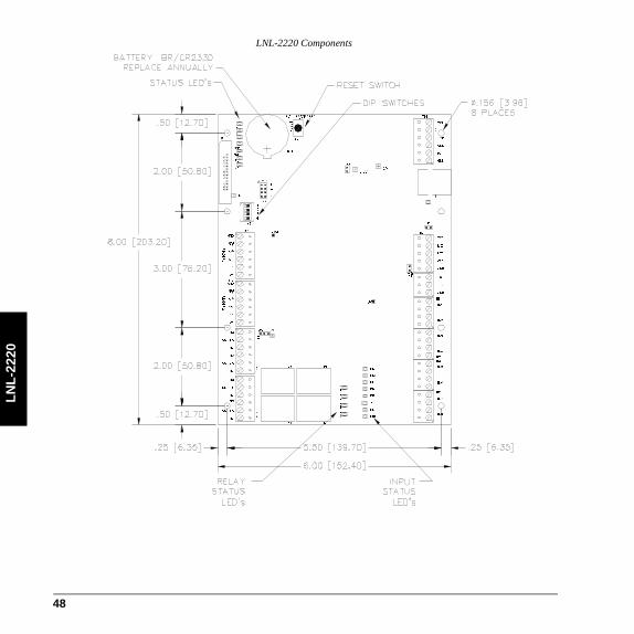
LNL-2220 Components
J4
J3
1
2
3
TMP
FLT
R1
R2
+
1
3
2
4
J8
RESET
S2
BT1
3V BR/CR2330
J1
5V3.3V
2
3
4
1
S1
VBAT
IN1
K
1
K
2
K
3
K
4
K2 K1
K3K4
IN2
IN3
IN4
IN5
IN6
IN7
IN8
8V
J6
J2
J5
J7
PASS 12V
GND
DATD0
TB8
READER
1 BZR
VO
GND
FLT
GND
TMP
GND
VIN
TB1
LED
D1CLK
READER
2
D1
LED
VO
BZR
GND
CLK
D0DAT
TB9
NO
OUT 1 C
NC
NO
OUT 2 C
NC
NC
OUT 4 C
NC
NO
NO
OUT 3 C
TB1
0
TB1
1
RXD
CTS
GND
RTS
TXD
TB2
TB3
TR+
GND
TR-
IN1
IN2
IN3
IN4
IN5
IN6
IN7
IN8
TB4
TB5
TB6
TB7
-
48

LN
L-2220
Wiring and Setup
Connection
TB1 Power input VIN: 12 to 24 VDC
GND
Cabinet tamper input TMP
GND
Power fault input FLT
GND
TB2 Host port 1 TXD (RS-232)
RXD (RS-232)
RTS (RS-232)
CTS (RS-232)
GND (RS-232)
TB3 Downstream port TR+ (2-wire RS-485)
TR- (2-wire RS-485)
GND(2-wire RS-485)
TB4 Input 1 IN 1Door 1 door contact
Input 2 IN 2Door 1 REx
49

LN
L-2
220
TB5 Input 3 IN 3Door 1 Aux 1
Input 4 IN 4Door 1 Aux 2
TB6 Input 5 IN 5Door 2 door contact
Input 6 IN 6Door 2 REx
TB7 Input 7 IN 7Door 2 Aux 1
Input 8 IN 8Door 2 Aux 2
TB8 Reader 1 (current maximum: 150mA)
GND: Ground
Data/Data 0/RS-485 TR-
Clock/Data 1/RS-485 TR+
BZR: Reader buzzer/LED 2
LED: Reader LED 1
VO: Reader power
Connection (Continued)
50

LN
L-2220
TB9 Reader 2 (current maximum: 150mA)
GND: Ground
Data/Data 0/RS-485 TR-
Clock/Data 1/RS-485 TR+
BZR: Reader buzzer/LED 2
LED: Reader LED 1
VO: Reader power
TB10 Out 1Door 1 strike
NO: Normally open contact
C: Common
NC: Normally closed contact
Out 2Door 1 Aux
NO: Normally open contact
C: Common
NC: Normally closed contact
TB11 Out 3Door 2 strike
NO: Normally open contact
C: Common
NC: Normally closed contact
Out 4Door 2 Aux
NO: Normally open contact
C: Common
NC: Normally closed contact
Connection (Continued)
51

LN
L-2
220
Communication WiringThe controller communicates to the host via the on-board 10Base-T/100Base-TX Ethernet interface (port 0) and/or RS-232 interface (port 1). The RS-232 interface is for direct one to one connection to a host computer port or via modem, 50 feet maximum. The downstream communication port (TB3) is a 2-wire RS-485 interface which can be used to connect additional I/O panels. The interface allows multi-drop communication on a single bus of up to 4000 feet (1200 m). Use twisted pairs (minimum 24 AWG) with an overall shield for communication.
Install the termination jumper ONLY on the panel at each end of the RS-485 bus. Failure to do so will compromise the proper operation of the communication channel!
Communication wiring
Reader WiringEach reader port supports wiegand, magnetic stripe, and 2-wire RS-485 electrical interfaces. Voltage at the reader port (VO) is passed-through from the input voltage of the controller (TB1-VIN) and is current limited to 150mA for each reader port. Readers that require different voltage or have high current
RXDTXD
RTSCTSGND
Port 1, RS-232 To Host(Wire with 24 AWG stranded)
TR-TR+
GND
To Downstream Devices(Wire with 24 AWG,
stranded twisted pair(s) with an overall shield)
TB2 TB3
52
LN
L-2220
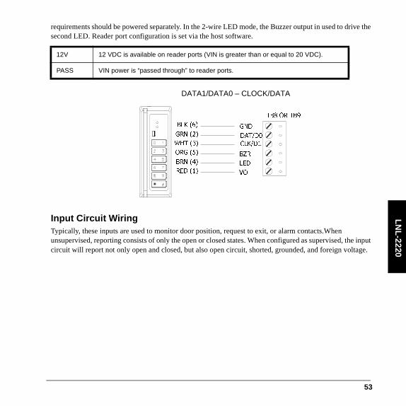
requirements should be powered separately. In the 2-wire LED mode, the Buzzer output in used to drive the second LED. Reader port configuration is set via the host software.
Input Circuit WiringTypically, these inputs are used to monitor door position, request to exit, or alarm contacts.When unsupervised, reporting consists of only the open or closed states. When configured as supervised, the input circuit will report not only open and closed, but also open circuit, shorted, grounded, and foreign voltage.
12V 12 VDC is available on reader ports (VIN is greater than or equal to 20 VDC).
PASS VIN power is “passed through” to reader ports.
BLK (6)
ORG (5)
BRN (4)
GRN (2)
RED (1)
WHT (3)
GND
DAT/D0
CLK/D1
BZR
LED
VO
TB8 OR TB9
DATA1/DATA0 – CLOCK/DATA
53

LN
L-2
220
A supervised input circuit requires two resistors be added to the circuit to facilitate proper reporting. The standard supervised circuit requires 1K Ohm, 1% resistors and should be located as close to the sensor as possible. Custom EOL resistances may be configured via the host software.
Relay Circuit WiringFour relays are provided for controlling door lock mechanisms or alarm signaling. The relay contacts are rated at 5A @ 30 VDC, dry contact configuration. Each relay has a Common pole (C), a Normally Open pole (NO) and a Normally Closed pole (NC). When you are controlling the delivery of power to the door strike, the Normally Open and Common poles are used. When you are momentarily removing power to unlock the door, as with a mag lock, the Normally Closed and Common poles are used. Check with local building codes for proper egress door installation.
Door lock mechanisms can generate feedback to the relay circuit that can cause damage and premature failure of the relay. For this reason, it is recommended that either a diode or MOV (metal oxide varistor) be used to protect the relay.
1K,1%
1K,1%
1K,1%
1K,1%
Standard Supervised Circuit,Normally Closed Contact
Standard Supervised Circuit,Normally Open Contact
Unsupervised Circuit,Normally Open Contact
Unsupervised Circuit,Normally Closed Contact
Terminal BlocksTB4 Through TB7
Wire with 22 AWG stranded twisted pair.
54

LN
L-2220
Wire should be of sufficient guage to avoid voltage loss.
• Diode Selection: Diode current rating: 1x strike current. Diode breakdown voltage 4x strike voltage. For 12 VDC or 24 VDCstrike, diode 1N4002 (100V/1A) typical.
• MOV Selection: Clamp voltage: 1.5x VAC RMS. For 24 VAC strike, Panasonic ERZC07DK470 typical.
Power and Alarm InputsThe LNL-2220 requires 12-24 VDC power. Locate power source as close to the unit as possible. Connect power with minimum of 18AWG wire.
NC
C
NO
NC
C
NO
TB10 or TB11
– +
NC
C
NO
NC
C
NO
TB10 or TB11
55

LN
L-2
220
Note: Connect the GND signal to earth ground in ONE LOCATION within the system! Multiple earth ground connections may cause ground loop problems and is not advised.
Observe POLARITY on 12-24 VDC input!
There are two dedicated inputs for cabinet tamper and UPS fault monitoring. Normal (safe) condition is a closed contact. If these inputs are not used, install a jumper wire.
Wiring for power, power fault, and cabinet tampering
Setting DIP Switches
Note: To clear the flash and ram on the board using DIP switches, set SW1 and SW2 to on and power up the board. Within 10 seconds, drop either of the switches (SW1 or SW2) to off.
Switch Selection:
SW1 When SW1 is on, use the default login username and password. (This can be changed without resetting the board.)Username: adminPassword: password
SW2 During power up, when SW2 is on (and SW1 is off) for the first 10 seconds, the default static IP address is 192.168.0.251, and the primary path is configured for IP Server, and the secondary path is configured for RS-232 at 38400 bps.When powering up the board with both SW1 and SW2 set to on for 10 seconds, the default communication setting for Lenel's OEM code is DHCP enabled.
SW3 When SW3 is on, it is used to disable SSL settings.
SW4 Not used.
VINGND
+-
12 to 24 VDC (wire power with stranded twisted pair, 18 AWG)
TMPGND
GNDFLT
CABINET TAMPER
POWER FAULT
56

LN
L-2220
Installing Jumpers
* Note 1: The input power (VIN) must be 20 VDC minimum if the 12 VDC selection is to be used.
** Note 2: Observe POLARITY connection to LED. External current limiting is not required.
Configuration via Web PageThe IDRC is configured through the web interface.
The Configuration Web Page can be launched from within System Administration (only if an IP address or host name is specified) or by using a browser to access the programmed IP address. Depending on your
Jumpers Set at Description
J1 n/a Factory use only
J2 n/a 10base-T/100base-Tx Ethernet Connection (Port 0)
J3 n/a Factory use only
J4 n/a Factory use only
J5 off Port 2 RS-485 EOL terminator is off.
ON Port 2 RS-485 terminator is ON.
J6 n/a Factory use only
J7 Reader power select * See Note 1 *
12V 12 VDC at reader ports
PASS VIN pass through to reader ports
J8-1 n/a Remote status LED #1 ** See Note 2 **
J8-2 n/a Remote status LED #2 ** See Note 2 **
J8-3 n/a Remote status LED #3 ** See Note 2 **
J8-4 n/a Remote status LED #4 ** See Note 2 **
57

LN
L-2
220
proxy settings, you may have to allow this web page. (For more information, consult your browser’s online help or system administrator for assistance.)
1. In System Administration in the Access Panels folder, click [Configuration Web Page]. This page will launch in a browser. (You may also access this page by going to the device IP address from within the browser.)
2. Click the link to go to the login page. Log in using your username and password. If DIP switch 1 is ON, then the default username and password is used (admin, password). If DIP switch 1 is off, use the login that was programmed in the device. Click [Login].
3. The Home page indicates the type of device and has a Notes field. You may type in a description here. Click [Save Notes].
4. To configure network settings, click [Network].
a. If you are using DHCP, specify a host name. By default, the host name consists of “MAC” followed by the numbers of the device MAC address. With DHCP, IP settings will be configured automatically.
b. For a static IP address, specify the IP address, subnet mask, and default gateway.
c. Click [Accept].
5. To configure the host, click [Host Comm].
a. Specify the controller’s communication address.
b. Configure the following:
– Connection Type: Choose IP Server, Serial-RS232, or Serial-modem. Currently the IP Client connection type is not supported.
– Data Security: The controller is capable of Password/AES encryption.
– Port Number (default 3001) Must match setting in the access control software.
When using an IP Server connection, the controller may be configured to allow all IP addresses or only authorized IP addresses.
c. Click [Accept].
6. To view information, click [Device Info].
You may view the time and product ID, as well as properties that have been configured, such as firmware version, serial number, OEM code, device name, DIP switches, etc.
58

LN
L-2220
7. For users configuration, click [Users].
User accounts may be created, edited or deleted. Each user account has an associated username and password, as well as a level and notes.
a. One of three different levels may be assigned to users.
– Level 1 — Full control
– Levels 2 and 3 have the following permissions:
For pages that cannot be viewed, the message is displayed when users attempt to access the page: “This page is unavailable due to one of the following reasons: your user level is not authorized to view this page, or another level 1 user is logged in at this time.”
b. Select the password strength.
c. Specify the Session Timer (5 to 60 minutes). Click [Save]
d. You may disable the web server by selecting the check box. When this option is selected and SW1 is off, all ports except for the host communication port will be disabled. The configuration web page cannot be used to access the device.
Access View allowed Edit allowed
Home page Level 2: Yes (cannot edit notes)Level 3: Yes (cannot edit notes)
Level 2: NoLevel 3: No
Network page Level 2: YesLevel 3: No
Level 2: NoLevel 3: No
Host Port page Level 2: YesLevel 3: No
Level 2: NoLevel 3: No
Device Info page Level 2: YesLevel 3: Yes
n/a
Users page Level 2: NoLevel 3: No
Level 2: NoLevel 3: No
Restore/Default page Level 2: NoLevel 3: No
Level 2: NoLevel 3: No
Apply Setting page Level 2: NoLevel 3: No
Level 2: NoLevel 3: No
59
LN
L-2
220
e. Select the Enable door forced open filter check box if you do not want a forced open alarm generated if the door is opened within three seconds of it being closed.
8. For configuration of auto-save, click [Auto-Save Config].
a. On this page, you may restore the last save or clear everything.
b. Choose to disable or enable Auto-Save. If Auto-Save is enabled, volatile memory is written to flash. The frequency of this action is specified in the timer (30 seconds to 30 minutes). Click [Save Settings].
9. You may click [Restore/Default] if you need to reload the factory settings or the current operating settings.
10. When you have completed configuring the device, click [Apply Setting], [Apply, Reboot], and then [Log Out].
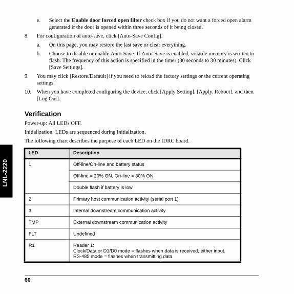
VerificationPower-up: All LEDs OFF.
Initialization: LEDs are sequenced during initialization.
The following chart describes the purpose of each LED on the IDRC board.
LED Description
1 Off-line/On-line and battery status
Off-line = 20% ON, On-line = 80% ON
Double flash if battery is low
2 Primary host communication activity (serial port 1)
3 Internal downstream communication activity
TMP External downstream communication activity
FLT Undefined
R1 Reader 1:Clock/Data or D1/D0 mode = flashes when data is received, either input.RS-485 mode = flashes when transmitting data
60

LN
L-2220
R2 Reader 2:Clock/Data or D1/D0 mode = flashes when data is received, either input.RS-485 mode = flashes when transmitting data
D16 Flashes with host communication (Ethernet port 0)
YEL Ethernet Speed: OFF = 10Mb/S, ON = 100Mb/S
GRN Off = no link, ON = good link, Flashing = Ethernet activity
IN1 Input IN1 Status: Off = Inactive, ON = Active, Flash = Trouble
IN2 Input IN2 Status: Off = Inactive, ON = Active, Flash = Trouble
IN3 Input IN3 Status: Off = Inactive, ON = Active, Flash = Trouble
IN4 Input IN4 Status: Off = Inactive, ON = Active, Flash = Trouble
IN5 Input IN5 Status: Off = Inactive, ON = Active, Flash = Trouble
IN6 Input IN6 Status: Off = Inactive, ON = Active, Flash = Trouble
IN7 Input IN7 Status: Off = Inactive, ON = Active, Flash = Trouble
IN8 Input IN8 Status: Off = Inactive, ON = Active, Flash = Trouble
K1 Relay K1: ON = energized
K2 Relay K2: ON = energized
K3 Relay K3: ON = energized
K4 Relay K4: ON = energized
LED Description
61

LN
L-2
220
SpecificationsThe IDRC is for use in low voltage, class 2 circuits only. These specifications are subject to change without notice.
• Primary Power: 12 to 24 VDC ±10%, 500 mA maximum (plus reader current)
- 12 VDC @ 250 mA (plus reader current) nominal- 24 VDC @ 150 mA (plus reader current) nominal
• Memory and Clock Backup: 3 V Lithium (Rayovac BR2325 or Wuhan Lixing CR2330)
• Host communication: Ethernet: 10Base-T/100Base-TX, and RS-232 9600 to 115,200 bps, asynchronous, half-duplex, 1 start bit, 8 data bits, and 1 stop bit.
• Downstream communication: 2-wire RS-485, 2400-38400 bps, asynchronous, half-duplex, 1 start bit, 8 data bits, and 1 stop bit.
• Inputs:
- 2 unsupervised, dedicated for tamper and UPS fault monitoring- 8 unsupervised/supervised, standard EOL: 1k/1k ohm. Four custom EOL’s are available (host
software dependent).• Relays: Four, Form-C, 5 A @ 30 VDC, resistive
• Reader interface:
- Reader power (jumper selectable): 12 VDC ±10% regulated, current limited to 150mA for each reader or 12 to 24 VDC ±10% (input voltage passed through) current limited to 150mA for each reader.
- Data inputs: TTL compatible inputs, mag stripe and wiegand standards supported- RS-485 mode: 9600 bps, asynchronous, half-duplex, 1 start bit, 8 data bits, and 1 stop bit.- LED output: TTL levels, high > 3V, low < 0.5 V, 5mA source/sink max.- Buzzer output: TTL levels, high > 3V, low < 0.5 V, low=active, 5mA source/sink max.
• Cable Requirements:
- Power: 1 stranded twisted pair, 18 AWG- Ethernet: Cat 5- RS-485: 24 AWG, stranded twisted pair(s) with an overall shield, 4000 feet (1219 m) maximum- RS-232: 24 AWG stranded, 50 feet (15.24 m) maximum- Alarm Input: stranded twisted pair, 30 ohms maximum, typically 22 AWG @ 1000 feet (300 m)
• Environmental:
- Temperature: 32 to 158° F(0 to 70° C) operating, -67 to +185° F (-55 to +85° C) storage- Humidity: 0 to 95% RHNC
62

LN
L-2220
• Mechanical:
- Dimensions: 8 x 6 x 1 in. (203.2 x 152.4 x 25 mm)- Weight: 9 oz. (255 g) nominal, board only
• Certifications:
- UL294 and UL1076 Listed, ULC Listed- FCC Part 15- C-Tick- FIPS 197 Certificate #766- CE marking- RoHS compliant- WEEE
63

LN
L-2
220
64
LN
L-3300
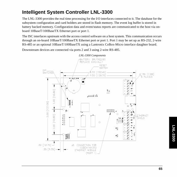
Intelligent System Controller LNL-3300The LNL-3300 provides the real time processing for the I/O interfaces connected to it. The database for the subsystem configuration and card holders are stored in flash memory. The event log buffer is stored in battery backed memory. Configuration data and event/status reports are communicated to the host via on-board 10BaseT/100BaseTX Ethernet port or port 1.
The ISC interfaces upstream with the access control software on a host system. This communication occurs through an on-board 10BaseT/100BaseTX Ethernet port or port 1. Port 1 may be set up as RS-232, 2-wire RS-485 or an optional 10BaseT/100BaseTX using a Lantronix CoBox-Micro interface daughter board.
Downstream devices are connected via ports 2 and 3 using 2-wire RS-485.
LNL-3300 Components
1
4
3
2
S1
VBAT
1
2
3
4
5
6
LNK
SPD
TB2
J1
J11
TXDTR+
RXDTR-
RTS
CTS
GND
PORT
1
485J7
232
J9
J8
J1
0
PORT
2
PORT
3
TR+
TR-
GND
TR+
TR-
GND
J4
J5
GND
FLT
GND
TMP
VIN
GN
D
ACT
3
.
3
V
5
V
J1 J13
J14
J15
J16
J17
- +
J3
S2
BT1
3V BR/CR2330
U1
U4U3
U5
U7
J6
J12
65

LN
L-3
300
Communication WiringThe ISC communicates to the host via: on-board Ethernet 10Base-T/100Base100-TX port or on port 1. Port 1 may be configured as RS-232, 2-wire RS-485 or optional Lantronix Ethernet 10baseT/100Base-TX CoBox-Micro interface. RS-232 interface is for direct one to one connection to a host computer port, or a modem.
Wiring port 1
Ports 2 and 3 utilize 2-wire RS-485 interface only. The interface allows multi-drop communication on a single bus of up to 4,000 feet (1,200 m). Use twisted pair (minimum 24 AWG) with shield for the communication with 120 ohm impedance. Install termination jumpers only at the end of line unit.
PORT 1 CONFIGURED as 2-WIRE RS-485
TXD/TR1+
RXD/TR1-
RTSCTS
GND
PORT 1 CONFIGURED as RS-232
GND
TXD/TR1+
RXD/TR1-
RTSCTS
Earth Ground
Wire with 24 AWG, stranded
66

LN
L-3300
Wiring ports 2 and 3
Power and Alarm InputsThe LNL-3300 accepts 12 to 24 VDC for power. Locate power source as close to the unit as possible. Connect power with minimum of 18 AWG wires. Inputs TMP and FLT are used for monitoring cabinet tamper and power failure with normally closed contacts. These two inputs are for contact closure monitoring only, and do not use EOL resistor(s). If these inputs are not used, install a short piece of wire at the input to indicate safe condition.
Observe POLARITY on VIN!
Wiring for power, power fault, and cabinet tampering
GND
TR3-TR3+
TR2-
TR2+
GND
GND
TR3-TR3+
TR2-
TR2+
GND
PORT 22-WIRE RS-485
PORT 32-WIRE RS-485
Earth Ground
Earth Ground
Wire with 24 AWG, stranded
VINGND
+-
12 to 24 VDC (wire power with stranded twisted pair, 18 AWG)
TMPGND
GNDFLT
CABINET TAMPER
POWER FAULT
67

LN
L-3
300
Setting DIP Switches
Note: To clear the flash and ram on the board using DIP switches, set SW1 and SW2 to on and power up the board. Within 10 seconds, drop either of the switches (SW1 or SW2) to off
Switch Selection:
SW1 When SW1 is on, use the default login username and password. (This can be changed without resetting the board.)Username: adminPassword: password
SW2 During power up, when SW2 is on (and SW1 is off) for the first 10 seconds, the default static IP address is 192.168.0.251, and the primary path is configured for IP Server, and the secondary path is configured for RS-232 at 38400 bps.When powering up the board with both SW1 and SW2 set to on for 10 seconds, the default communication setting for Lenel's OEM code is DHCP enabled.
SW3 When SW3 is on, it is used to disable SSL settings.
SW4 Not used.
68

LN
L-3300
Installing Jumpers
Note: Observe POLARITY connection to LED. External current limiting is not required.
Jumpers Set at Description
J2 n/a Factory use only
J3 n/a Factory use only
J4 off Port 2 RS-485 EOL terminator is off.
ON Port 2 RS-485 terminator is ON.
J5 off Port 3 RS-485 EOL terminator is off.
ON Port 3 RS-485 terminator is ON.
J6 n/a Lantronix CoBox-micro connection - port 1
J7, J8, J9 232 Port 1 is RS-232
485 Port 1 is RS-485
J10 off Port 1 RS-485 EOL terminator is off.
ON Port 1 RS-485 terminator is ON.
J11 n/a Factory use only
J12 n/a Factory use only
J13 n/a Factory use only
J14 n/a Remote status LED #1 (see note below)
J14 n/a Remote status LED #2 (see note below)
J15 n/a Remote status LED #3 (see note below)
J16 n/a Remote status LED #4 (see note below)
69

LN
L-3
300
Configuration via Web PageThe Configuration Web Page can be launched from within System Administration (only if an IP address or host name is specified) or by using a browser to access the programmed IP address. Depending on your proxy settings, you may have to allow this web page. (For more information, consult your browser’s online help or system administrator for assistance.)
1. In System Administration in the Access Panels folder, click [Configuration Web Page]. This page will launch in a browser. (You may also access this page by going to the device IP address from within the browser.)
2. Click the link to go to the login page. Log in using your username and password. If DIP switch 1 is ON, then the default username and password is used (admin, password). If DIP switch 1 is off, use the login that was programmed in the device. Click [Login].
3. The Home page indicates the type of device and has a Notes field. You may type in a description here. Click [Save Notes].
4. To configure network settings, click [Network].
a. If you are using DHCP, specify a host name. By default, the host name consists of “MAC” followed by the numbers of the device MAC address. With DHCP, IP settings will be configured automatically.
b. For a static IP address, specify the IP address, subnet mask, and default gateway.
c. Click [Accept].
5. To configure the host, click [Host Comm].
a. Specify the controller’s communication address.
b. Configure the following:
– Connection Type: Choose IP Server, Serial-RS232, or Serial-modem, Serial-RS485 (LNL-3300 only) and Serial-Cobox (LNL-3300 only). Currently the IP Client connection type is not supported.
– Data Security: The controller is capable of Password/AES encryption.
– Port Number (default 3001) Must match setting in the access control software.
When using an IP Server connection, the controller may be configured to allow all IP addresses or only authorized IP addresses.
c. Configure an alternate host port if needed. If you opt NOT to use dual path communication, set this to Disabled.
70

LN
L-3300
d. Click [Accept].
6. To view information, click [Device Info].
You may view the time and product ID, as well as properties that have been configured, such as firmware version, serial number, OEM code, device name, DIP switches, etc.
7. For users configuration, click [Users].
User accounts may be created, edited or deleted. Each user account has an associated username and password, as well as a level and notes.
a. One of three different levels may be assigned to users.
– Level 1 — Full control
– Levels 2 and 3 have the following permissions:
For pages that cannot be viewed, the message is displayed when users attempt to access the page: “This page is unavailable due to one of the following reasons: your user level is not authorized to view this page, or another level 1 user is logged in at this time.”
Access View allowed Edit allowed
Home page Level 2: Yes (cannot edit notes)Level 3: Yes (cannot edit notes)
Level 2: NoLevel 3: No
Network page Level 2: YesLevel 3: No
Level 2: NoLevel 3: No
Host Port page Level 2: YesLevel 3: No
Level 2: NoLevel 3: No
Device Info page Level 2: YesLevel 3: Yes
n/a
Users page Level 2: NoLevel 3: No
Level 2: NoLevel 3: No
Restore/Default page Level 2: NoLevel 3: No
Level 2: NoLevel 3: No
Apply Setting page Level 2: NoLevel 3: No
Level 2: NoLevel 3: No
71

LN
L-3
300
b. Select the password strength.
c. Specify the Session Timer (5 to 60 minutes). Click [Save]
d. You may disable the web server by selecting the check box. When this option is selected and SW1 is off, all ports except for the host communication port will be disabled. The configuration web page cannot be used to access the device.
e. Select the Enable door forced open filter check box if you do not want a forced open alarm generated if the door is opened within three seconds of it being closed.
8. For configuration of auto-save, click [Auto-Save Config].
a. On this page, you may restore the last save or clear everything.
b. Choose to disable or enable Auto-Save. If Auto-Save is enabled, volatile memory is written to flash. The frequency of this action is specified in the timer (30 seconds to 30 minutes). Click [Save Auto-Save Timer].
9. You may click [Restore/Default] if you need to reload the factory settings or the current operating settings.
10. When you have completed configuring the device, click [Apply Setting], [Apply, Reboot], and then [Log Out].
72

LN
L-3300
VerificationThe ISC board contains six status LEDs that can be used to verify correct installation after power up.
The following chart describes the purpose of each LED on the ISC board.
Initialization :
LED 1 LED 2 LED 3 LED 4 LED 5 LED 6 Purpose
ON off off off off off Basic processor initialization
ON ON off off off off Internal SRAM test
ON off ON off off off External flash test
ON ON ON off off off External SDRAM, first chip test
ON off off ON off off External SDRAM, second chip test
ON ON off ON off off External SRAM test
ON off ON ON off off External EEPROM test
ON ON ON ON off off External RTC test
ON off off off ON off Backup battery ABD reset circuit test
ON ON off off ON off UART test
ON off ON off ON off Ethernet interface, MII
73

LN
L-3
300
Run time :
LED Description
1 Off-line/on-line and battery status
Off-line = 20% ON. On-line = 80% ON
Double flash if battery is low
2 Primary host communication activity (Ethernet or port 1)
3 Port 2 communication activity
4 Port 3 communication activity
5 ON = writing to flash memory. Do not remove power when ON.
6 TBD
SPD On-board Ethernet speed: off = 10 Mb/S, ON = 100 Mb/S
ACT Off = no on-board Ethernet activity, ON = Ethernet activity (yellow LED)
LNK Off = no link, ON = good link (green LED)
74

LN
L-3300
Specifications** The ISC is for use in low voltage, class 2 circuits only. These specifications are subject to change without notice.
• Primary Power: 12 to 24 VDC ±10%, 300 mA maximum
- 12VDC @ 240 mA (325 mA with CoBox-Micro) nominal- 24VDC @ 135 mA (175 mA with CoBox-Micro) nominal
• Memory and Clock Backup: 3 V Lithium (Rayovac BR2325 or Wuhan Lixing CR2330)
• Communication Ports:
- Port 1: RS-232 or 2-wire RS-485: 9,600 to 115,200 bps, async- Ports 2 and 3: 2-wire RS-485: 2,400 to 38,400 bps, async
• Inputs: two non-supervised, dedicated for cabinet tamper and power fault monitoring
• Cable Requirements:
- Power: 1 stranded twisted pair, 18 AWG- RS-485: 24 AWG stranded twisted pair(s) with shield, 4000 feet (1219 m) maximum, 120 Ohm- RS-232: 24 AWG stranded, 50 feet (15.24 m) maximum- Ethernet: Cat 5- Alarm inputs: stranded twisted pair, 30 ohms maximum
• Environmental:
- Temperature: 32 to 158° F(0 to 70° C) operating, -67 to +185° F (-55 to +85° C) storage- Humidity: 0 to 95% RHNC
• Mechanical:
- Dimension: 5 in. x 6 in. x 1 in. (127 x 152.4 x 25mm)- Weight: 4.1 oz. (115 g) nominal
• Lantronix NIC support: Standoff size - Diameter .125 inch x 7/16 inch long. Richco Plastics part number LMSP-7-01, 3 pieces (Not supplied)
• Certifications:
- UL294 and UL1076 Listed, ULC Listed- FCC Part 15- C-Tick- FIPS 197 Certificate #767- CE marking- RoHS compliant- WEEE
75

LN
L-3
300
76

LN
L-1100
Input Control Module LNL-1100 Series 2The Lenel Input Control Module (ICM) provides the access control system with high-speed acknowledgement of critical alarm points in monitored areas. The ICM communicates directly with the Intelligent System Controller (ISC) either by RS-485 communication. The ICM has 16 configurable input control points and 2 output control relays. It supports normally open, normally closed, supervised and non-supervised circuits.
The input circuits are scanned using an analog to digital converter. The digitized input status signal is software monitored and controlled, so that each input point can be programmed as a supervised or non-supervised alarm point.
77

LN
L- 1
100
LNL-1100 Components
TB11
VIN
GND
TR-
R+
R-
GND
TR+
TB10
4W
2W
RS-485
TB1
TB2
TB3
TB4
TB9
I1
I1
I2
I2
I3
I3
I4
I4
I5
I5
I6
I6
I7
I7
I8
I8
CT
GND
BA
GND
2W
4W
J3
J6 J5
1
2
3
4
5
6
7
8
S1
NC
C
NO
NC
C
NO
OUT 1
OUT 2
TB12
K1
K2
J8
TB5
I9
I9
I10
I10
TB6
I11
I11
I12
I12
TB7
I13
I13
I14
I14
TB8
I15
I15
I16
I16
A
B
K1
K2
J9
J7
J4
J1
J2
RS-
485
TERM
U1
1
2
3
4
5
6
7
8
9
10
11
12
13
14
15
16
CT
BA
78

LN
L-1100
Status LEDsThe series 2 Input Control Module contains LEDs that can be used to verify correct installation after power up.
Power-up: All LED’s OFF.
Initialization: Once power is applied, initialization of the module begins.
The A LED is turned on at the beginning of initialization. If the application program cannot be run, the A LED will flash at a rapid rate. The ICM is waiting for firmware to be downloaded.
When initialization is completed, LEDs 1 through 16, CT and BA are briefly sequenced ON then OFF.
Run time: After the above sequence, the LEDs have the following meanings:
A LED: Heartbeat and On-Line Status:
• Off-line: 1 second rate, 20% ON
• On-line: 1 second rate, 80% ON
B LED: Communication Port Status:
• Indicates communication activity on the communication port
1 LED: Input Status: 12 LED: Input Status: 23 LED: Input Status: 34 LED: Input Status: 45 LED: Input Status: 56 LED: Input Status: 67 LED: Input Status: 78 LED: Input Status: 89 LED: Input Status: 910 LED: Input Status: 1011 LED: Input Status: 1112 LED: Input Status: 1213 LED: Input Status: 1314 LED: Input Status: 1415 LED: Input Status: 1516 LED: Input Status: 16CT: Cabinet TamperBA: Power Fault
79

LN
L- 1
100
Input in the inactive state: OFF (briefly flashes ON every 3 seconds)
Input in the active state: ON (briefly flashes OFF every 3 seconds)
Input in a fault state: Rapid Flash
LED K1 and K2: correspond to output relay RLY 1 (K1) or RLY 2 (K2) is energized.
Unsupervised Alarm InputsWire the BA (power fault) and CT (cabinet tamper) inputs using a twisted pair cable, 30 ohms maximum (no EOL resistors required). If either of these inputs is not used, a shorting wire should be installed.
GND
IN 2
GND
IN 1
CABINETTAMPER
POWERFAULT
80

LN
L-1100
Software Configurable Alarm InputsEach input that is configured as a supervised alarm must be terminated with two (2) 1000-ohm resistors (1% tolerance - 0.25 watt. N/O and N/C alarms are terminated identically).
1K, 1%
1K, 1%
I9
I9
I10
I10
I11
I11
I12
I12
1K, 1%
1K, 1%
NC
NO
NC
NO
Supervised
Unsupervised
81

LN
L- 1
100
Upstream Controller CommunicationThe Input Control Module uses Port 1 to communicate to the Intelligent System Controller. The RS-485 is asynchronous, half-duplex, using 1 start bit, 8 data bits, 1 stop bit.
Relay OutputsTwo form-C contact relays are provided for controlling door strikes or other devices. Load switching can cause abnormal contact wear and premature contact failure. Switching of inductive loads (strike) also causes EMI (electromagnetic interference) which may interfere with normal operation of other equipment. To minimize premature contact failure and to increase system reliability, contact protection circuit must be used. The following two circuits are recommended. Locate the protection circuit as close to the load as
TR +
TR -
SG
2W
RS-485 2-WIRE COMMUNICATIONS
T+ T- SG
Earth Ground
Wire with 24 AWG stranded twisted pair with shield
82

LN
L-1100
possible (within 12 inches [30cm]), as the effectiveness of the circuit will decrease if it is located further away. Use sufficiently large gauge of wires for the load current as to avoid voltage loss.
12 VDC
+ -
NC
CNO
NO
NC
C
DIODE 1N4002 (100V/1A) TYPICALDIODE CURRENT RATING > 1X STRIKE CURRENTDIODE BREAK DOWN VOLTAGE > 4X STRIKE VOLTAGE
-
+
DC STRIKE
ACXFMR
NC
C
NO
NO
NC
C
FOR 24 VAC STRIKE, PANASONIC ERZ-C07DK470MOV SELECTION: CLAMP VOLTAGE > 1.5 X VAC RMS
AC STRIKE
83

LN
L- 1
100
PowerThe ICM accepts 12 to 24 VDC for power. Locate power source as close to the unit as possible. Connect power with minimum of 18AWG wires.
DIP SwitchesDevice Address
Address DIP SWITCH
5: 4: 3: 2: 1:
0 off off off off off
1 off off off off ON
2 off off off ON off
3 off off off ON ON
4 off off ON off off
5 off off ON off ON
6 off off ON ON off
7 off off ON ON ON
8 off ON off off off
9 off ON off off ON
10 off ON off ON off
VIN
GND
+
-12 to 24 VDC
Wire with 18 AWG stranded twisted pair.
84

LN
L-1100
11 off ON off ON ON
12 off ON ON off off
13 off ON ON off ON
14 off ON ON ON off
15 off ON ON ON ON
16 ON off off off off
17 ON off off off ON
18 ON off off ON off
19 ON off off ON ON
20 ON off ON off off
21 ON off ON off ON
22 ON off ON ON off
23 ON off ON ON ON
24 ON ON off off off
25 ON ON off off ON
26 ON ON off ON off
27 ON ON off ON ON
28 ON ON ON off off
Device Address (Continued)
Address DIP SWITCH
5: 4: 3: 2: 1:
85
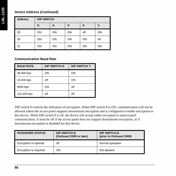
LN
L- 1
100
DIP switch 8 controls the utilization of encryption. When DIP switch 8 is ON, communication will not be allowed unless the access panel supports downstream encryption and is configured to enable encryption to this device. When DIP switch 8 is off, the device will accept either encrypted or unencrypted communication. It must be off if the access panel does not support downstream encryption, or if downstream encryption is disabled for this device.
29 ON ON ON off ON
30 ON ON ON ON off
31 ON ON ON ON ON
Communication Baud Rate
BAUD RATE DIP SWITCH 6: DIP SWITCH 7:
38,400 bps ON ON
19,200 bps off ON
9600 bps ON off
115,200 bps off off
PASSWORD STATUS DIP SWITCH 8:(OnGuard 2009 or later)
DIP SWITCH 8:(prior to OnGuard 2009)
Encryption is optional off Normal operation
Encryption is required ON Not allowed
Device Address (Continued)
Address DIP SWITCH
5: 4: 3: 2: 1:
86

LN
L-1100
Installing JumpersThe jumpers must be configured appropriately for your system.
TB 11
VIN
GND
TR-
R+
R-
GND
TR+
TB 10
4W
2W
RS-
485
TB1
TB 2
TB 3
TB4
TB 9
I1
I1
I2
I2
I3
I3
I4
I4
I5
I5
I6
I6
I7
I7
I8
I8
CT
GND
BA
GND
2W
4W
J3
J6 J5
1
2
3
4
5
6
7
8
S1
NC
C
NO
NC
C
NO
OUT 1
OUT 2
TB12
K1
K
2
J8
TB5
I9
I9
I10
I10
TB6
I11
I11
I12
I12
TB7
I13
I13
I14
I14
TB8
I15
I15
I16
I16
A
B
K1
K2
J9
J7
J4
J1
J2
R
S-
485
TE
RM
U
1
1
2
3
4
5
6
7
8
9
10
11
12
13
14
15
16
CT
BA
[J1]RS-485 termination. Install in first and last units only.OFF: Termination is not onON: Termination is on
[J3]2-wire select: install in 2W position only.
J3
87

LN
L- 1
100
SpecificationsThe LNL-1100 is for use in low voltage, class 2 circuits only. These specifications are subject to change without notice.
• Primary power: 12 to 24 VDC + 10%, 350 mA maximum
- 12 VDC @ 300 mA nominal- 24 VDC @ 220 mA nominal
• Output: Two (2) outputs, Form-C, 5 A @ 28 VDC resistive
• Inputs:
- Sixteen (16) unsupervised/supervised, standard EOL: 1k/1k ohm, 1%, 1/4 watt- Two (2) unsupervised, dedicated for cabinet tamper and UPS fault monitoring
• Communication: RS-485, 2-wire, 9600 to 115,200 bps
• Cable requirements:
- Power: 18 AWG, 1 stranded twisted pair- RS-485: 24 AWG, 120 ohm impedance, stranded twisted pair with shield, 4000 feet (1219 m)
maximum- Alarm inputs:1 stranded twisted pair, 30 ohms maximum- Outputs: as required for the load
• Mechanical:
- Dimension: 6 x 8 x 1 in. (152 x 203 x 25 mm)- Weight: 9 oz. (280 g) nominal
• Environmental:
- Temperature: 32 to 158° F(0 to 70° C) operating, -67 to +185° F (-55 to +85° C) storage- Humidity: 0 to 95% RHNC
• Certifications:
- UL294 and UL1076 Listed, ULC Listed- FCC Part 15- C-Tick- CE marking- RoHS compliant- WEEE
88

LN
L-1100-U
Input Control Module LNL-1100-UThe Input Control Module (ICM) board contains the following components: sixteen (16) software configurable alarm inputs, two (2) unsupervised alarm inputs, two (2) alarm output relays, one (1) RS-485 interface, power input, DIP switches, and jumpers.
ICM board (Dimensions are in inches [mm])
Installation1. Set baud rate (SW1), address (SW2), and LED control switches.
2. Install jumpers.
3. Mount the board in the enclosure.
Note: The LNL-CONV-U1 Universal Mounting Plate is required when installing the board into a CTX enclosure. For more information, refer to Mounting on page 97.
4. Wire the unsupervised alarm inputs for power fault and cabinet tamper.
5. Wire the supervised alarm inputs.
89

LN
L-1
1 00-
U
6. Wire the upstream host communication.
7. Wire the relay outputs.
8. Wire the power and communications inputs.
9. Validate proper operation on power up.
ConfigurationThe Input Control Module board contains two (2) 8-position DIP switches that are user-selectable to control addressing, baud rate, and other user functions, and one (1) RS-485 termination jumper used to configure the system.
Setting DIP SwitchesICM DIP switches
90

LN
L-1100-U
Communication Baud Rate (SW1)Configure the baud rate using SW1 switches 1-4. (Switch 5 is used for LED control. Switches 6-8 are not used).
LED ModeSW1 switch 5 is used for LED control. It is read at boot time. If you make a change to this setting, be sure to restart.
Note: The status LEDs only function when the cabinet tamper switch is open (cabinet door is open). When the cabinet tamper switch is closed (cabinet door is closed), the status LEDs are off.
Baud rate SW1 switch for host SW1 switch for OSDP readers (Aux ports)
1: 2: 3: 4:
2400 bps off off off off
9600 bps ON off ON off
19200 bps off ON off ON
38400 bps ON ON ON ON
SW1 Switch 5 State
ON LEDs behave as the Access (LNL) series module.
off LED behavior is in Normal Mode
91

LN
L-1
1 00-
U
Device Address (SW2)Configure the board address using SW2. (Switches 6-8 are not used.)
Address SW2 switch
1: 2: 3: 4: 5:
0 off off off off off
1 ON off off off off
2 off ON off off off
3 ON ON off off off
4 off off ON off off
5 ON off ON off off
6 off ON ON off off
7 ON ON ON off off
8 off off off ON off
9 ON off off ON off
10 off ON off ON off
11 ON ON off ON off
12 off off ON ON off
13 ON off ON ON off
14 off ON ON ON off
15 ON ON ON ON off
16 off off off off ON
92
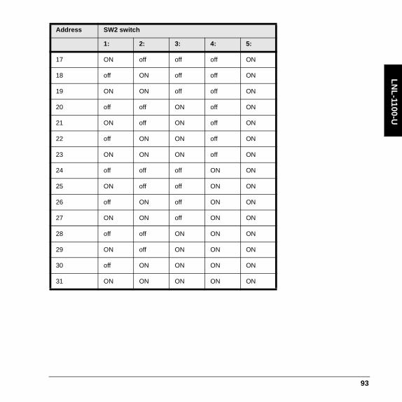
LN
L-1100-U
17 ON off off off ON
18 off ON off off ON
19 ON ON off off ON
20 off off ON off ON
21 ON off ON off ON
22 off ON ON off ON
23 ON ON ON off ON
24 off off off ON ON
25 ON off off ON ON
26 off ON off ON ON
27 ON ON off ON ON
28 off off ON ON ON
29 ON off ON ON ON
30 off ON ON ON ON
31 ON ON ON ON ON
Address SW2 switch
1: 2: 3: 4: 5:
93

LN
L-1
1 00-
U
Installing JumpersJumper configuration
Host Communications: Jumper J22 pins 1 & 2 for RS-485 communications termination. Install jumper on the last ICM on the communications line for proper termination of the communications bus. (For more information, refer to the ICM upstream wiring diagram.)
Status LEDsNote: The status LEDs only function when the cabinet tamper switch is open (cabinet door is open).
When the cabinet tamper switch is closed (cabinet door is closed), the status LEDs are off.
LED Table for Series 2 LNL-1100 ModeWhen switch 5 is in the ON position, the LEDs behave like the series 2 LNL-1100.
LED Table for Normal ModeWhen SW1 switch 5 is in the off position, the LEDs operate in Normal Mode.
Indication LED State
Power-up ALL Off
Initialization D79 Flashing
After initialization D79 Offline: 1 second rate, 20% ONOnline: 1 second rate, 80% ON
Communications D1 ON
94
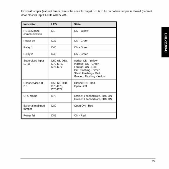
LN
L-1100-U
External tamper (cabinet tamper) must be open for Input LEDs to be on. When tamper is closed (cabinet door closed) Input LEDs will be off.
Indication LED State
RS-485 panel communication
D1 ON - Yellow
Power on D37 ON - Green
Relay 1 D40 ON - Green
Relay 2 D48 ON - Green
Supervised input I1-I16
D59-66, D68, D70-D73, D75-D77
Active: ON - YellowInactive: ON - GreenForeign: ON - RedCut: Flashing - GreenShort: Flashing - RedGround: Flashing - Yellow
Unsupervised I1-I16
D59-66, D68, D70-D73, D75-D77
Closed ON - Red,Open - Off
CPU status D79 Offline: 1 second rate, 20% ONOnline: 1 second rate, 80% ON
External (cabinet) tamper
D80 Open ON - Red
Power fail D82 ON - Red
95

LN
L-1
1 00-
U
CPU status LED D79 possible module error conditions for LED Normal and Series 2 modes:
Error condition Flashing pattern
Description
No valid application firmware 3 Red, 2 Green
The module is not operational. Firmware must be loaded using a console, e.g. HyperTerminal with Xmodem.
Boot loader waiting on firmware file
3 Red, 1 Green
Console boot loader is waiting on start of firmware file.
Boot loader loading firmware file
2 Red, 2 Green
Console boot loader is loading a firmware file.
Invalid EFL file 1 Red, 2 Green
The EFL specified to be loaded using the console loader is not a valid EFL file.
Invalid Xmodem packet 1 Red, 1 Green
The console loader received an invalid Xmodem packet and terminated the firmware download operation.
Invalid Application firmware for module CPU
3 Red, 0 Green
The module is not operational. Application firmware loaded on the module will not run properly. Requires new firmware be loaded using the console boot loader or the module must be returned for repair.
Invalid Boot firmware for module CPU
2 Red, 3 Green
The module is not operational. Boot loader firmware loaded on the module will not run properly. The module must be returned for repair.
Firmware update failed 1 Red, 3 Green
Firmware update operation was unsuccessful. Retry and if it fails continuously, load a different firmware file.
No valid primary firmware copy
3 Green, 2 Red
The firmware flash contains 2 copies of the application firmware. The primary copy is not valid so the backup copy will be loaded into the primary copy and executed.
96

LN
L-1100-U
MountingThe ICM can be mounted in the LNL-AL400ULX or LNL-AL600ULX-4CB6 and the LNL-CTX or LNL-CTX6 enclosure using the Universal Mounting Plate (UMP) LNL-CONV-U1.
No valid backup firmware copy
3 Green, 1 Red
The firmware flash contains 2 copies of the application firmware. The backup copy is not valid so the primary copy will be loaded into the backup copy.
No valid manufacturing parameters
3 Green, 0 Red
The manufacturing parameters which include the serial number, etc. are invalid. The module must be returned for repair.
Error condition Flashing pattern
Description
97

LN
L-1
1 00-
U
Mounting the ICM in the LNL-AL400ULX and LNL-CTX
98

LN
L-1100-U
Mounting the ICM in the LNL-AL600ULX-4CB6 or LNL-CTX6
WiringWire inputs I1 through I16 (J9 - J16) using a twisted pair cable, 30 ohms maximum, 24 AWG minimum.
99

LN
L-1
1 00-
U
ICM input wiring
Note: See Input Resistor Table for termination resistor values.
Supervised (Software Configurable) Alarm InputsThe 16 inputs available on the ICM are software configurable alarm inputs that can be used for alarm device monitoring. Each of these inputs can be configured, via the Access Control software, as either N/O (normally open) or N/C (normally closed) in combination with either supervised or unsupervised wiring. These alarm inputs are connected using Inputs 1 - 16.
Each input that is configured as a supervised alarm must also be terminated with two (2) 1K (1000) ohm resistors (1% tolerance - 1/4 (0.25) watt. N/O and N/C alarms are terminated identically). Resistors are provided with the module.
Install the resistors as close to input device as possible. For cable length limitations, see Specifications.
100

LN
L-1100-U
Unsupervised Alarm Inputs: Power Fail and External (Cabinet) TamperThe Input Control Module features two (2) unsupervised alarm inputs that can be used for power fail and cabinet tamper monitoring. These inputs are connected using the power fail and external (cabinet) tamper contact terminals on the Input Control Module board.
The power fail and external tamper inputs are simple N/C (normally closed) contact closure monitors. Connect the power fail monitoring device to J20 pins 1 & 3 and to External Tamper (cabinet tamper) pins 4 & 6. If not used, a jumper must be installed across pins 1 & 3 and 4 & 6.
Note: Input Status LEDs will be off when the tamper device is in the closed position or the jumper is installed.
Wire the power fail and external tamper inputs using twisted pair cable, 30 ohms maximum. (No EOL resistors are required.)
Input Resistor Table
Alarm Zone Contact NC Alarm Zone Contact NO
Normal 1K ± 10% 2K ± 10%
Alarm 2K ± 10% 1K ± 10%
Fault – Line Short 0 – 50 0 – 50
Fault – Line Open 15K – ∞ 15K – ∞Fault – Foreign Voltage 50 – 750
1250 – 15002500 – 15K
50 – 7501250 – 15002500 – 15K
101

LN
L-1
1 00-
U
Unsupervised alarm input wiring (Power Fail and External Tamper contacts)
Upstream Controller CommunicationThe ICM uses Port 1 to communicate to the Intelligent System Controller.
Port 1 is a 2-wire RS-485 interface, that requires the following type of RS-485 cable: 24 AWG (minimum) twisted pair (with shields). The main run RS-485 cable should be no longer than 4000 feet [1219 m], 100 ohms maximum (Belden 9841, West Penn, or equivalent). The drop cables (to downstream devices) should be kept as short as possible, no longer than 10 feet [3.048 m].
The RS-485 communication is asynchronous, half-duplex, using 1 start bit, 8 data bits, 1 stop bit.
Note: RS-485 communication is supported for upstream communication only.
102

LN
L-1100-U
ICM upstream wiring
To enable RS-485 termination, install jumper on pin header J22 (on the last unit on the communication line).
Notes: The (EIA) Electronic Industries Association standard defines RS-485 as an electrical interface for multi-port communications on a bus transmission line. It allows for high-speed data transfer over extended distances (4000 feet [1219m]). The RS-485 interface uses a balance of differential transmitter/receiver to reject common mode noise. For increased reliability over the extended distances, End-Of-Line (EOL) termination is required.
RS-485 must be terminated at both ends of the RS-485 line (bus). Terminating the line provides a more reliable communication by minimizing the signal reflection and external noise coupling. Each component provided has an on-board terminator. The installer should determine which device is at the end of the communication line.
Control Output WiringContact protection circuit must be used. The following two circuits are recommended. Locate the protection circuit as close to the load as possible (within 12 inches [30cm]), as the effectiveness of the circuit will decrease if it is located farther away.
103

LN
L-1
1 00-
U
Relay OutputsRelay contact (DC strike)
Relay contact (AC strike)
104

LN
L-1100-U
Elevator ControlOnGuard hardware is capable of supporting elevator control for up to 128 floors. An elevator reader has an input/output module that controls the access to floors via an elevator.
The OnGuard software must be configured for elevator control. This can be done from System Administration by selecting the Elevator check box on the General tab in the Readers and Doors form. The reader’s type, name, port, address, and access panel can all be defined here as well.
Note: In order for this check box to be available, the access panel to which this reader module is connected must have Elevator support enabled on the Options tab.
With elevator control on the LNL-1300 reader, door strike and contact are not available, and REX (Request to EXit) is disabled.
Addresses assigned to input/output panels do not need to be consecutive. On the first panel, the inputs/outputs represent the first sixteen floors (e.g.: Input 1 = first floor, Input 2 = second floor, etc.). The second panel represents the next sixteen floors (floor 17 through 32), etc.
105

LN
L-1
1 00-
U
Overview of elevator control
Power and CommunicationsThe Input Control Module requires a 12 to 24 VDC ± 10% power source for its input power.
Intelligent System Controller
Output Control Module
Elevator Reader
(inside cab)
Input Control Module
Access Control System
Elevator Control Room
Up to 128 Outputs - eight Output Control
Modules
Up to 128 Inputs - eight Input Control
Modules
Single Reader Interface
Single Reader
Interface Module
Single Reader
Interface
Maximum: 4000 feet
(1219.2 meters)5 conductors
106

LN
L-1100-U
Wire the Power In input with 18 AWG (minimum) twisted pair cable.
Note: Be sure to observe polarity.
Power source wiring
Power Source Requirements Current
DC power source Isolated, non-switching, regulated DC power
300mA for 12VDC150mA for 24VDC
107

LN
L-1
1 00-
U
SpecificationsThe LNL-1100-U is for use in low voltage, class 2 circuits only. These specifications are subject to change without notice.
• Primary power: 12 to 24 VDC + 10%
- 12 VDC @ 300 mA nominal- 24 VDC @ 150 mA nominal- 12.3 BTU/hour
• Output: Two (2) outputs, Form-C contacts: Relay 1 and 2 (K1 and K2), 5 A @ 30 VDC
• Inputs:
- Sixteen (16) unsupervised/supervised, standard EOL: 1k/1k ohm, 1%, 1/4 watt- One (1) unsupervised, dedicated external (cabinet) tamper- One (1) unsupervised, AC power fail
• Upsteam communication: RS-485, 2-wire, 2400 to 38400 bps
- Does not support encryption• Cable requirements:
- Power: 18 AWG, 1 stranded twisted pair- RS-485: 24 AWG, 120 ohm impedance, stranded twisted pair with shield, 4000 feet (1219 m)
maximum- Alarm inputs: 1 stranded twisted pair, 30 ohms maximum- Outputs: as required for the load
• Mechanical:
- Dimension: 5 x 8 x 1.25 in. (127 x 203 x 32 mm)- Weight: 6.2 oz. (188 g) nominal
• Environmental:
- Temperature: -10 to +70°C (14 to 158° F) operating, -40 to +85°C (-40 to 185°F) storage- Humidity: 10% at 93°C (199°F) non-condensing operating, 10 to 95% at 85°C (185°F) non-
condensing storage• Certifications:
- FCC compliance: This equipment has been tested and found to comply with the limits for a Class A digital device, pursuant to part 15 of the FCC Rules. These limits are designed to provide reasonable protection against harmful interference when the equipment is operated in a commercial environment. This equipment generates, uses, and can radiate radio frequency
108

LN
L-1100-U
energy and, if not installed and used in accordance with the instruction manual, may cause harmful interference to radio communications.
- UL294, UL1076, and S319 Listed- ULC Listed- C-Tick N22193- CE marking- RoHS- Environmental class: Indoor dry - WEEE
European Union directives: 2002/96/EC (WEEE directive): Products marked with this symbol cannot be disposed of as unsorted municipal waste in the European Union. For proper recycling, return this product to your local supplier upon the purchase of equivalent new equipment, or dispose of it at designated collection points. For more information see: www.recyclethis.info.
109

LN
L-1
1 00-
U
110

LN
L-1200
Output Control Module LNL-1200 Series 2The Lenel Output Control Module (OCM) communicates directly with the Intelligent System Controller (ISC) by RS-485 communication. Each OCM is an individually addressed device, and counts as a single device on all ISCs.
LNL-1200 Components
S1
1
1 2 43 5 12976 8 13 1410 11 15 16
TB1
0
TR+
GND
R+4W
R-
2W
TR-
RS-
485
GND
VIN
GND
BA
CT
GND
TB9
TB1
1
J2
J1
J1, J2
RS-485
TERM
NC
C
NO
NC
C
NO
OUT 8
OUT 7
TB4
K8
NO
C
NC
NO
C
NCOUT 6
OUT 5
NO
C
NC
NO
C
NC
OUT 4
OUT 3
NO
C
NC
NO
C
NCOUT 2
OUT 1
TB3
K7
TB2
TB1
2W
4W
J3
U1
J6
J5
J7
J8
J4
A
B
CT
BA
2
3
4
5
6
7
8
K2
K4
K3
K1 K9
K11
K12
K10
K5 K13
K14
K1
5
K1
6
TB5
TB6
TB7
TB8
NO
C
NC
NO
C
NC
OUT 9
OUT 10
C
NO
NC
C
NO
NC
OUT 11
OUT 12
NC
C
OUT 13NO
NC
OUT 14NO
C
OUT 16NO
C
OUT 15
NC
C
NO
NC
K6
111

LN
L-1
200
Status LEDsThe series 2 Output Control Module contains a total of 20 LEDs to verify correct installation after power up.
Power-up: All LED’s OFF.
Initialization: Once power is applied, initialization of the module begins.
The A LED is turned on at the beginning of initialization. If the application program cannot be run, the A LED will flash at a rapid rate. The OCM is waiting for firmware to be down loaded.
When initialization is completed, LEDs A, B, CT and BA are briefly sequenced ON then OFF.
Run time: After the above sequence, the LEDs have the following meanings:
A LED: Heartbeat and Online Status:
• Offline: 1 second rate, 20% ON.
• Online: 1 second rate, 80% ON.
B LED: Communication Port Status:
• Indicates communication activity on the communication port.
CT: Cabinet Tamper.
BA: Power Fault.
Input in the inactive state: OFF (briefly flashes ON every 3 seconds).
Input in the active state: ON (briefly flashes OFF every 3 seconds).
LEDs 1 through 16: correspond to output relay OUT 1 (K1) through OUT 16 (K16).
112

LN
L-1200
Unsupervised Alarm InputsWire the BA (power fault) and CT (cabinet tamper) inputs using a twisted pair cable, 30 ohms maximum (no EOL resistors required). If either of these inputs is not used, a shorting wire should be installed.
Upstream Controller CommunicationThe Output Control Module uses Port 1 to communicate to the Intelligent System Controller. The RS-485 is asynchronous, half-duplex, using 1 start bit, 8 data bits, 1 stop bit.
CT
GND
BA
GND
CABINETTAMPER
POWERFAULT
TR +
TR -
SG
2WRS-485 2-WIRE COMMUNICATIONS
T+ T- SG
Earth Ground
Wire with 24 AWG stranded twisted pair with shield
113

LN
L-1
200
Relay Outputs
Power Source WiringThe power source should be located as close to the Output Control Module as possible. Be sure to observe polarity.
DC SOURCE
AC SOURCE
NC
C
NO
NC
C
NO
FUSE
+
-
LOAD
LOAD
MOV
FUSE
VIN
GND
+
-12 to 24 VDC
Wire with 18 AWG stranded twisted pair.
114

LN
L-1200
DIP SwitchesDevice Address
Address DIP SWITCH
5: 4: 3: 2: 1:
0 off off off off off
1 off off off off ON
2 off off off ON off
3 off off off ON ON
4 off off ON off off
5 off off ON off ON
6 off off ON ON off
7 off off ON ON ON
8 off ON off off off
9 off ON off off ON
10 off ON off ON off
11 off ON off ON ON
12 off ON ON off off
13 off ON ON off ON
14 off ON ON ON off
15 off ON ON ON ON
16 ON off off off off
115

LN
L-1
200
17 ON off off off ON
18 ON off off ON off
19 ON off off ON ON
20 ON off ON off off
21 ON off ON off ON
22 ON off ON ON off
23 ON off ON ON ON
24 ON ON off off off
25 ON ON off off ON
26 ON ON off ON off
27 ON ON off ON ON
28 ON ON ON off off
29 ON ON ON off ON
30 ON ON ON ON off
31 ON ON ON ON ON
Device Address (Continued)
Address DIP SWITCH
5: 4: 3: 2: 1:
116

LN
L-1200
DIP switch 8 controls the utilization of encryption.
When DIP switch 8 is ON, communication will not be allowed unless the access panel supports downstream encryption and is configured to enable encryption to this device.
When DIP switch 8 is off, the device will accept either encrypted or unencrypted communication. It must be off if the access panel does not support downstream encryption, or if downstream encryption is disabled for this device.
Communication Baud Rate
BAUD RATE DIP SWITCH 6: DIP SWITCH 7:
38,400 bps ON ON
19,200 bps off ON
9600 bps ON off
115,200 bps off off
PASSWORD STATUS DIP SWITCH 8:(OnGuard 2009 or later)
DIP SWITCH 8:(prior to OnGuard 2009)
Encryption is optional off Normal operation
Encryption is required ON Not allowed
117

LN
L-1
200
Installing JumpersThe jumpers must be configured appropriately for your system.
[J1]RS-485 termination. Install in first and last units only.OFF: Termination is not onON: Termination is on
S1
1
1 2 43 5 12976 8 13 1410 11 15 16
TB1
0
TR+
GND
R+4W
R -
2W
TR -
R
S-
485
GND
VIN
GND
BA
CT
GND
TB9
TB1
1
J
2
J1
NC
C
NO
NC
C
NO
OUT 8
OUT 7
TB
4
K
8
NO
C
NC
NO
C
NCOUT 6
OUT 5
NO
C
NC
NO
C
NC
OUT 4
OUT 3
NO
C
NC
NO
C
NCOUT 2
OUT 1
TB
3
K7
TB2
T
B1
2W
4W
J3
U1
J 6
J5
J7
J8
J4
A
B
CT
BA
2
3
4
5
6
7
8
K2
K4
K3
K 1 K9
K11
K12
K10
K5K13
K14
K1
5
K1
6
TB5
TB6
TB7
TB8
NO
C
NC
NO
C
NC
OUT 9
OUT 10
C
NO
NC
C
NO
NC
OUT 11
OUT 12
NC
C
OUT 13NO
NC
OUT 14NO
C
OUT 16NO
C
OUT 15
NC
C
NO
NC
K6
[J3]2-wire select: install in 2W position only.
J3
118
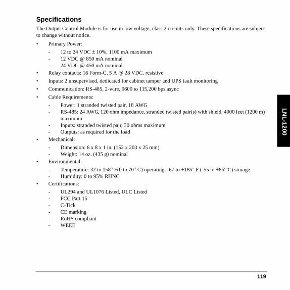
LN
L-1200
SpecificationsThe Output Control Module is for use in low voltage, class 2 circuits only. These specifications are subject to change without notice.
• Primary Power:
- 12 to 24 VDC ± 10%, 1100 mA maximum- 12 VDC @ 850 mA nominal- 24 VDC @ 450 mA nominal
• Relay contacts: 16 Form-C, 5 A @ 28 VDC, resistive
• Inputs: 2 unsupervised, dedicated for cabinet tamper and UPS fault monitoring
• Communication: RS-485, 2-wire, 9600 to 115,200 bps async
• Cable Requirements:
- Power: 1 stranded twisted pair, 18 AWG- RS-485: 24 AWG, 120 ohm impedance, stranded twisted pair(s) with shield, 4000 feet (1200 m)
maximum- Inputs: stranded twisted pair, 30 ohms maximum- Outputs: as required for the load
• Mechanical:
- Dimension: 6 x 8 x 1 in. (152 x 203 x 25 mm)- Weight: 14 oz. (435 g) nominal
• Environmental:
- Temperature: 32 to 158° F(0 to 70° C) operating, -67 to +185° F (-55 to +85° C) storage- Humidity: 0 to 95% RHNC
• Certifications:
- UL294 and UL1076 Listed, ULC Listed- FCC Part 15- C-Tick- CE marking- RoHS compliant- WEEE
119

LN
L-1
200
120
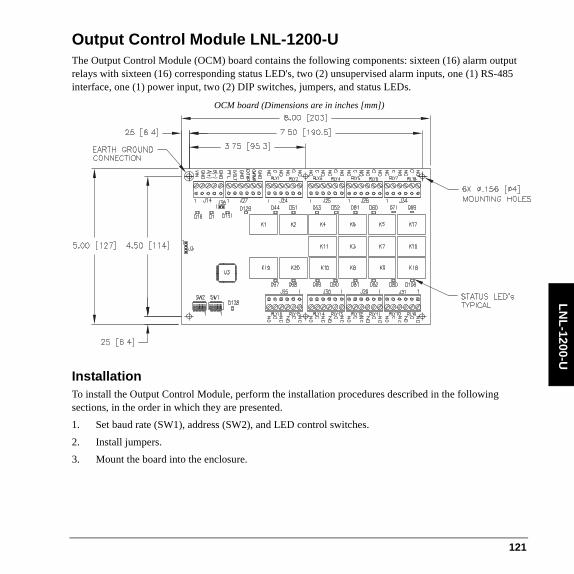
LN
L-1200-U
Output Control Module LNL-1200-UThe Output Control Module (OCM) board contains the following components: sixteen (16) alarm output relays with sixteen (16) corresponding status LED's, two (2) unsupervised alarm inputs, one (1) RS-485 interface, one (1) power input, two (2) DIP switches, jumpers, and status LEDs.
OCM board (Dimensions are in inches [mm])
InstallationTo install the Output Control Module, perform the installation procedures described in the following sections, in the order in which they are presented.
1. Set baud rate (SW1), address (SW2), and LED control switches.
2. Install jumpers.
3. Mount the board into the enclosure.
121

LN
L-1
200-
U
Note: The LNL-CONV-U1 Universal Mounting Plate is required when installing the board into a CTX enclosure. For more information, refer to Mounting on page 128.
4. Wire the unsupervised alarm inputs for power fail and external (cabinet) tamper.
5. Wire the upstream host communication.
6. Wire the relay outputs.
7. Wire the power and communications inputs.
8. Validate proper operation on power up.
ConfigurationThe Output Control Module board contains two (2) 8-position DIP switches that are user selectable to control addressing, baud rate, and other user functions, and one (1) RS-485 termination jumper used to configure the system.
Setting DIP Switches
122

LN
L-1200-U
Communication Baud Rate (SW1)Configure the baud rate using SW1 switches 1 and 2. (Switches 3 through 8 are not used.)
Device Address (SW2)Configure the board address using SW2. (Switches 6-8 are not used.)
Baud rate SW1 switch for host
1: 2:
2400 bps off off
9600 bps ON off
19200 bps off ON
38400 bps ON ON
Address SW2 switch
1: 2: 3: 4: 5:
0 off off off off off
1 ON off off off off
2 off ON off off off
3 ON ON off off off
4 off off ON off off
5 ON off ON off off
6 off ON ON off off
7 ON ON ON off off
123

LN
L-1
200-
U
8 off off off ON off
9 ON off off ON off
10 off ON off ON off
11 ON ON off ON off
12 off off ON ON off
13 ON off ON ON off
14 off ON ON ON off
15 ON ON ON ON off
16 off off off off ON
17 ON off off off ON
18 off ON off off ON
19 ON ON off off ON
20 off off ON off ON
21 ON off ON off ON
22 off ON ON off ON
23 ON ON ON off ON
24 off off off ON ON
25 ON off off ON ON
26 off ON off ON ON
Address SW2 switch
1: 2: 3: 4: 5:
124

LN
L-1200-U
Installing JumpersJumper configuration
To enable RS-485 termination, install jumper on pin header J36. For more information, refer to the Upstream Communication section.
Host Communications: Jumper J36 pins 1 & 2 for RS-485 communications. Install the jumper on the last OCM on the communications line.
27 ON ON off ON ON
28 off off ON ON ON
29 ON off ON ON ON
30 off ON ON ON ON
31 ON ON ON ON ON
Address SW2 switch
1: 2: 3: 4: 5:
125

LN
L-1
200-
U
Status LEDsLED Table
Indication LED State
RS-485 panel communication
D1 ON - Yellow
Power on D18 ON - Green
Relay 1 D44 ON - Green
Relay 2 D51 ON - Green
Relay 3 D53 ON - Green
Relay 4 D52 ON - Green
Relay 5 D61 ON - Green
Relay 6 D60 ON - Green
Relay 7 D71 ON - Green
Relay 8 D69 ON - Green
Relay 9 D108 ON - Green
Relay 10 D80 ON - Green
Relay 11 D82 ON - Green
Relay 12 D81 ON - Green
Relay 13 D90 ON - Green
Relay 14 D89 ON - Green
Relay 15 D98 ON - Green
Relay 16 D97 ON - Green
126

LN
L-1200-U
CPU status LED D128 possible module error conditions:
CPU status D128 Offline: 1 second rate, 20% ONOnline: 1 second rate, 80% ON
External (cabinet) tamper
D129 Open ON - Red
Power fail D131 ON - Red
Error condition Flashing pattern
Description
No valid application firmware
3 Red, 2 Green
The module is not operational. Firmware must be loaded using a console, e.g. HyperTerminal with Xmodem.
Boot loader waiting on firmware file
3 Red, 1 Green
Console boot loader is waiting on start of firmware file.
Boot loader loading firmware file
2 Red, 2 Green
Console boot loader is loading a firmware file.
Invalid EFL file 1 Red, 2 Green
The EFL specified to be loaded using the console loader is not a valid EFL file.
Invalid Xmodem packet 1 Red, 1 Green
The console loader received an invalid Xmodem packet and terminated the firmware download operation.
Invalid Application firmware for module CPU
3 Red, 0 Green
The module is not operational. Application firmware loaded on the module will not run properly. Requires new firmware be loaded using the console boot loader or the module must be returned for repair.
Invalid Boot firmware for module CPU
2 Red, 3 Green
The module is not operational. Boot loader firmware loaded on the module will not run properly. The module must be returned for repair.
LED Table (Continued)
Indication LED State
127

LN
L-1
200-
U
MountingThe OCM can be mounted in the LNL-AL400ULX or LNL-AL600ULX-4CB6 and the LNL-CTX or LNL-CTX6 enclosure using the Universal Mounting Plate (UMP) LNL-CONV-U1.
Firmware update failed 1 Red, 3 Green
Firmware update operation was unsuccessful. Retry and if it fails continuously, load a different firmware file.
No valid primary firmware copy
3 Green, 2 Red
The firmware flash contains 2 copies of the application firmware. The primary copy is not valid so the backup copy will be loaded into the primary copy and executed.
No valid backup firmware copy
3 Green, 1 Red
The firmware flash contains 2 copies of the application firmware. The backup copy is not valid so the primary copy will be loaded into the backup copy.
No valid manufacturing parameters
3 Green, 0 Red
The manufacturing parameters which include the serial number, etc. are invalid. The module must be returned for repair.
Error condition Flashing pattern
Description
128

LN
L-1200-U
Mounting the OCM in the LNL-AL400ULX and LNL-CTX
129

LN
L-1
200-
U
Mounting the OCM in the LNL-AL600ULX-4CB6 or LNL-CTX6
Wiring
Unsupervised Alarm Inputs: Power Fail and External (Cabinet) TamperThe Output Control Module features two (2) unsupervised alarm inputs that can be used for power fail and external (cabinet) tamper monitoring. These inputs are connected using the power fail and external tamper contact terminals located on the Output Control Module.
The power fail and external tamper inputs are simple N/C (normally closed) contact closure monitors.
Wire the power fail and external tamper inputs using twisted pair cable, 30 ohms maximum (No EOL resistors are required).
Connect the power fail monitoring device to J27 pins 1 & 3 and the External Tamper (cabinet tamper) pins 4 & 6. If not used, a jumper must be installed across pins 1 & 3 and 4 & 6.
130
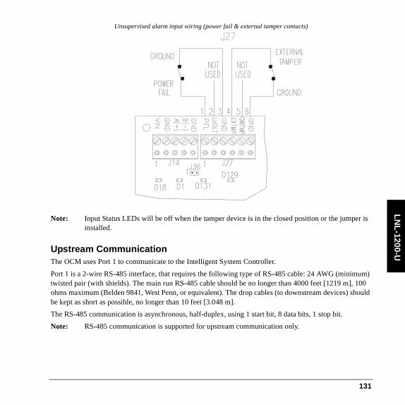
LN
L-1200-U
Unsupervised alarm input wiring (power fail & external tamper contacts)
Note: Input Status LEDs will be off when the tamper device is in the closed position or the jumper is installed.
Upstream CommunicationThe OCM uses Port 1 to communicate to the Intelligent System Controller.
Port 1 is a 2-wire RS-485 interface, that requires the following type of RS-485 cable: 24 AWG (minimum) twisted pair (with shields). The main run RS-485 cable should be no longer than 4000 feet [1219 m], 100 ohms maximum (Belden 9841, West Penn, or equivalent). The drop cables (to downstream devices) should be kept as short as possible, no longer than 10 feet [3.048 m].
The RS-485 communication is asynchronous, half-duplex, using 1 start bit, 8 data bits, 1 stop bit.
Note: RS-485 communication is supported for upstream communication only.
131

LN
L-1
200-
U
Upstream wiring
To enable RS-485 termination, install jumper on pin header J36.
Notes: The (EIA) Electronic Industries Association standard defines RS-485 as an electrical interface for multi-port communications on a bus transmission line. It allows for high-speed data transfer over extended distances (4000 feet/1219 m). The RS-485 interface uses a balance of differential transmitter/receiver to reject common mode noise. For increased reliability over the extended distances, End-Of-Line (EOL) termination is required.
RS-485 (2-wire or 4-wire) must be terminated at both ends of the RS-485 line (bus). Terminating the line provides a more reliable communication by minimizing the signal reflection and external noise coupling. Each component provided has an on-board terminator. The installer should determine which device is at the end of the communication line.
Relay OutputsThe Output Control Module contains sixteen (16) form-C dry-contact relay outputs, Relay 1 through 16 (K1-K11 & K16-K20). Each is rated at 5A 30VDC.
Transient clamping must be provided to protect the output contacts and to reduce EMI emissions.
For AC-powered devices, use MOV across the load. For DC-powered devices, use a diode across the load
132

LN
L-1200-U
Relay contact (DC strike)
133

LN
L-1
200-
U
Relay contact (AC strike)
Elevator ControlOnGuard hardware is capable of supporting elevator control for up to 128 floors. An elevator reader has an input/output module that controls the access to floors via an elevator.
The OnGuard software must be configured for elevator control. This can be done from System Administration by selecting the Elevator check box on the General tab in the Readers and Doors form. The reader’s type, name, port, address, and access panel can all be defined here as well.
134

LN
L-1200-U
Note: In order for this check box to be available, the access panel to which this reader module is connected must have Elevator support enabled on the Options tab.
With elevator control on the LNL-1300 reader, door strike and contact are not available, and REX (Request to EXit) is disabled.
Addresses assigned to input/output panels do not need to be consecutive. On the first panel, the inputs/outputs represent the first sixteen floors (e.g.: Input 1 = first floor, Input 2 = second floor, etc.). The second panel represents the next sixteen floors (floor 17 through 32), etc.
Overview of elevator control
Intelligent System Controller
Output Control Module
Elevator Reader
(inside cab)
Input Control Module
Access Control System
Elevator Control Room
Up to 128 Outputs - eight Output Control
Modules
Up to 128 Inputs - eight Input Control
Modules
Single Reader Interface
Single Reader
Interface Module
Single Reader
Interface
Maximum: 4000 feet
(1219.2 meters)5 conductors
135
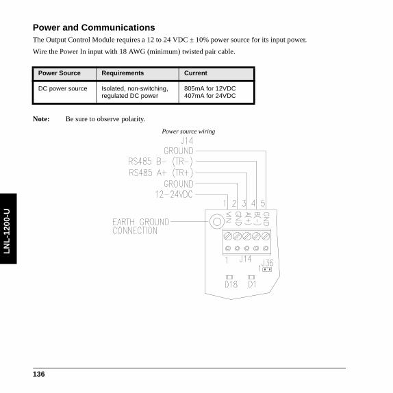
LN
L-1
200-
U
Power and CommunicationsThe Output Control Module requires a 12 to 24 VDC ± 10% power source for its input power.
Wire the Power In input with 18 AWG (minimum) twisted pair cable.
Note: Be sure to observe polarity.
Power source wiring
Power Source Requirements Current
DC power source Isolated, non-switching, regulated DC power
805mA for 12VDC407mA for 24VDC
136

LN
L-1200-U
SpecificationsThe LNL-1200-U is for connection to low voltage, class 2 power-limited circuits only. These specifications are subject to change without notice.
• Primary Power: 12 to 24 VDC ± 10%
- 12 VDC @ 805 mA nominal- 24 VDC @ 407 mA nominal- 33 BTU/hour
• Relay contacts: 16 Form-C contacts: Relay 1-16 (K1-K11, K16-K20), 5 A @ 30 VDC
• Inputs:
- One (1) unsupervised, dedicated external (cabinet) tamper- One (1) unsupervised, AC power fail
• Upstream communication: RS-485 2-wire, 2400 to 38400 bps
- Does not support encryption• Cable Requirements:
- Power: 1 stranded twisted pair, 18 AWG- RS-485: 24 AWG, 120 ohm impedance, stranded twisted pair(s) with shield, 4000 feet (1219 m)
maximum- Inputs:1 stranded twisted pair, 30 ohms maximum- Outputs: as required for the load
• Mechanical:
- Dimension: 5 x 8 x 1.25 in. (127 x 203 x 32 mm)- Weight: 12.2 oz. (346 g) nominal
• Environmental:
- Temperature: -10 to +70°C (14 to 158° F) operating, -40 to +85°C (-40 to 185°F) storage- Humidity: 10% at 93°C (199°F) non-condensing operating, 10 to 95% at 85°C (185°F) non-
condensing storage• Certifications:
- FCC Part 15- FCC compliance: This equipment has been tested and found to comply with the limits for a
Class A digital device, pursuant to part 15 of the FCC Rules. These limits are designed to provide reasonable protection against harmful interference when the equipment is operated in a commercial environment. This equipment generates, uses, and can radiate radio frequency
137

LN
L-1
200-
U
energy and, if not installed and used in accordance with the instruction manual, may cause harmful interference to radio communications.
- ETL 294, s319- UL294, 1076- C-Tick N22193- CE marking- RoHS- Environmental class: Indoor dry - WEEE
European Union directives: 2002/96/EC (WEEE directive): Products marked with this symbol cannot be disposed of as unsorted municipal waste in the European Union. For proper recycling, return this product to your local supplier upon the purchase of equivalent new equipment, or dispose of it at designated collection points. For more information see: www.recyclethis.info.
138

LN
L-1300
Single Reader Interface Module LNL-1300 Series 2The Single Reader Interface (SRI) supports access control card readers, keypads, or readers with keypads that use standard Wiegand Data1/Data0 or Clock/Data communications. Lock, unlock, and facility code offline access modes are supported on all readers connected to the SRI.
The SRI provides a vital link between the Intelligent System Controller (ISC) and the card reader attached to the interface. As many as 32 SRI modules can be multi-dropped using RS-485 2-wire communication, up to 4000 feet per port away from the ISC. Each SRI module is individually addressed for increased reporting capabilities with OnGuard Access Control software applications. The SRI includes two inputs that support normally open, normally closed, supervised, and non-supervised circuits. Two output relays support fail-safe or fail-secure operation.
LNL-1300 Components
1 2 3 4 5 6 7 8
J2
TB1
GND
J3
J5
TR-
TR+
VO
D0
DAT
GND
D1
LED
CLK
BZR
TB4
J4
B A
U1
J6
TB3
TB2
K2
K1
I1
I1
I2
I2
GND
VIN
C
NC
NO
C
NO
NC
K2
K1
2.
35
[
59.
7]
2.
75
[
69.
9]
3.85 [97.8]
4.25 [108]
TAMPER INPUT , NORMALLY CLOSED
STATUS LEDs.2 [5 .1]
.2 [5 .1]
Ø.156 [Ø4.0]
4 PLACES
139

LN
L-1
300
Status LEDsThe series 2 Single Reader Interface Module board contains two (2) status LEDs.
Power-up: All LEDs off.
Initialization: Once power is applied, initialization of the module begins.
The A LED is turned ON at the beginning of initialization. If the application program cannot be run, the A LED will flash at a rapid rate. The MR-50 is waiting for firmware to be down loaded.
Run time: After a successful initialization, the LEDs have the following meanings:
A LED: Heartbeat and On-Line Status:
• Offline: 1 second rate, 20% ON
• Online: 1 second rate, 80% ON
B LED: Communication Port Status:
Indicates communication activity on the communication port
140

LN
L-1300
WiringThe Single Reader Interface Module contains two (2) supervised alarm inputs that can be used for door position and REX exit push button monitoring. Wire the I1 and I2 inputs using a twisted pair cable, 30 ohms maximum. Terminate each of these inputs with two (2) 1000-ohm resistors (1% tolerance - 0.25 watt).
K1
K2
NORMALLY CLOSED
COMMON
NORMALLY OPEN
NORMALLY OPEN
NORMALLY CLOSED
COMMON
+12 VOLT DC
12 VDC RETURN
STRIKE RELAY
AUX RELAY
NO
NC
1K, 1%
1K, 1%
1K, 1%
1K, 1%
EXIT REQUESTNORMALLY OPEN
DOOR CONTACTNORMALLY CLOSED
NC
C
NO
NO
NC
C
VIN
GND
I2
I2
I1
I1
1 2 3 4 5 6 7 8
J4
GND
TR-
TR+
VO
DAT/D0
DAT/D1
LED
BZR
GND
J3
GROUND
BUZZER
LED
DATA1/CLOCK/TR+
DATA0/DATA/TR-
READER POWER
DATA1/CLOCK/TR+
DATA0/DATA/TR-
GROUND
READER
SIO COMM.RS-485
INTERFACE
TAMPER, NC
141

LN
L-1
300
Upstream Controller CommunicationThe Single Reader Interface Module uses Port 1 to communicate to the Intelligent System Controller.
TO ADDITIONALSIO UNITS
ISC
TR
+ TR
-S
G
INTERFACEINTERFACE
1 2 3 4 5 6 7 8
J4
GND
TR-
TR+
1 2 3 4 5 6 7 8
J4
GND
TR-
TR+
LAST UNIT ON COMMUNICATION LINE – TERMINATOR INSTALLED
142

LN
L-1300
Relay OutputsRelay contact (DC strike)
Relay contact (DC strike)
12 VDC
+ -
NC
C
NO
NO
NC
C
DIODE 1N4002 (100V/1A) TYPICALDIODE CURRENT RATING > 1X STRIKE CURRENTDIODE BREAK DOWN VOLTAGE > 4X STRIKE VOLTAGE
-
+
DC STRIKE
ACXFMR
NC
CNO
NO
NC
C
FOR 24 VAC STRIKE, PANASONIC ERZ-C07DK470MOV SELECTION: CLAMP VOLTAGE > 1 .5 X VAC RMS
AC STRIKE
143

LN
L-1
300
Downstream Reader CommunicationThe Single Reader Interface Module can communicate downstream with one (1) keypad or card reader. Power, reader, and door hardware wiring:
Cabinet TamperJumper J3 must be configured for Cabinet Tamper. There are two possible configuration options: On or Off. When J3 is on, cabinet tamper is bypassed. When it is off, it must be wired in order to work.
PowerThe Single Reader Interface Module requires a filtered 12VDC ± 15% power source for its power input. The power source must provide isolated and non-switching, linear regulated DC power, with 125 mA current.
Black - GND
Orange - BZR
Brown - LED
White - CLK/D1
Green - DAT/D0
Red - +12V
144

LN
L-1300
Installing JumpersJumper(s) configuration for the device communication address, communication baud rate, and RS-485 termination status:
1
2
3
4
5
6
7
8
86
7
115200 9600 19200 38400
0 1 2 3 4 5
BAUD RATE
I/O LINK ENCRYPTION off
6 7
8 9 10 11 12 13 14 15
16 17 18
1 2
3
4
51
2
3
4 5
19 20 21 22 23
1 2
3
4
5
24
1 2
3
4
5
25 26 27 28 29 30 31
J3
J4
J5
J6
CABINET TAMPER, NORMALLY CLOSED
RS-485 EOL, ON = ENGAGED FOR EOL UNIT
FACTORY USE ONLY
FACTORY USE ONLY
I/O LINK ENCRYPTION ON
145

LN
L-1
300
SpecificationsThe LNL-1300 is for use in low voltage, class 2 circuits only. These specifications are subject to change without notice.
• Primary power:
- 12 to 24 VDC + 10%, 150 mA maximum (plus reader current)- 12 VDC @ 110 mA (plus reader current) nominal- 24 VDC@ 60 mA (plus reader current) nominal
• Outputs: Form-C contacts: K1: 5 A @ 28 VDC, K2: 1 A @28 VDC
• Inputs:
- 2 supervised, End of Line resistors, 1k/1k ohm, 1% 1/4 watt standard- 1 unsupervised, dedicated for cabinet tamper
• Reader Interface:
- Reader power: 12 to 24 VDC ± 10% (input voltage passed through)- Reader LED output: TTL compatible, high > 3 V, low < 0.5 V, 5 mA source/sink maximum- Buzzer output: Open collector, 5 VDC open circuit maximum, 10 mA sink maximum- Reader data inputs: TTL compatible inputs or 2-wire RS-485
• Communication: RS-485, 2-wire. 9600, 19200, 38400, or 115200 bps
• Cable requirements:
- Power: 18 AWG, 1 stranded twisted pair- RS-485 24 AWG, 120 ohm impedance, stranded twisted pair with shield, 4000 feet (1219 m)
maximum- Alarm Inputs: 1 stranded twisted pair per input, 30 ohms maximum- Outputs: As required for the load- Reader data (TTL): 18 AWG stranded, 6 conductor, 500 feet (150 m) maximum- Reader data (RS-485): 24 AWG, 120 ohm impedance, stranded twisted pair with shield, 4000
(1,219 m) maximum• Mechanical:
- Dimension: 4.25 x 2.75 x 1.4 in. (108 x 74 x 36 mm)- Weight: 4 oz. (120 g) nominal
• Environmental:
- Temperature: -31 to +167° F (-35 to +75° C) operating, -67 to +185° F (-55 to +85° C) storage- Humidity: 0 to 95% RHNC
• Certifications:
146

LN
L-1300
- UL294 and UL1076 Listed, ULC Listed- FCC Part 15- C-Tick- CE marking- RoHS compliant- WEEE
147

LN
L-1
300
148
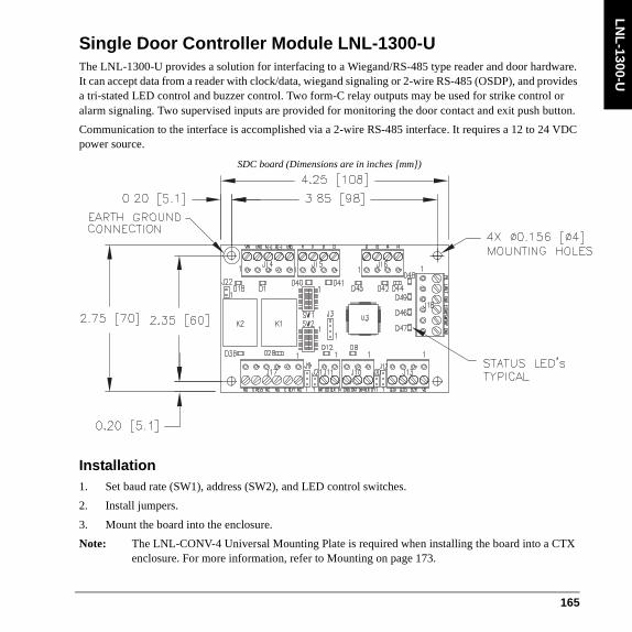
LN
L-1300-U
Single Door Controller Module LNL-1300-UThe LNL-1300-U provides a solution for interfacing to a Wiegand/RS-485 type reader and door hardware. It can accept data from a reader with clock/data, wiegand signaling or 2-wire RS-485 (OSDP), and provides a tri-stated LED control and buzzer control. Two form-C relay outputs may be used for strike control or alarm signaling. Two supervised inputs are provided for monitoring the door contact and exit push button.
Communication to the interface is accomplished via a 2-wire RS-485 interface. It requires a 12 to 24 VDC power source.
SDC board (Dimensions are in inches [mm])
Installation1. Set baud rate (SW1), address (SW2), and LED control switches.
2. Install jumpers.
3. Mount the board into the enclosure.
Note: The LNL-CONV-4 Universal Mounting Plate is required when installing the board into a CTX enclosure. For more information, refer to Mounting on page 173.
165

LN
L-1
300-
U
4. Wire the supervised alarm inputs for door position and REX exit push button monitoring.
5. Wire the upstream host communication.
6. Wire the relay outputs for door strike and AUX.
7. Wire the downstream interface for the keypad or card reader.
8. Wire tamper input.
9. Wire power and communications inputs.
10. Validate proper operation on power up.
ConfigurationThe Single Door Controller (SDC) board contains two (2) 8-position DIP switches that are user-selectable to control addressing, baud rate, and other functions, and four jumpers used to configure your system.
Setting DIP SwitchesSDC dip switches
166
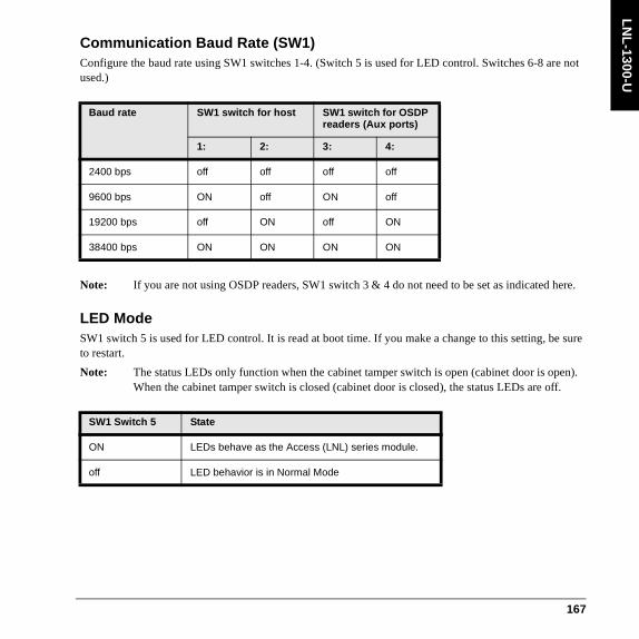
LN
L-1300-U
Communication Baud Rate (SW1)Configure the baud rate using SW1 switches 1-4. (Switch 5 is used for LED control. Switches 6-8 are not used.)
Note: If you are not using OSDP readers, SW1 switch 3 & 4 do not need to be set as indicated here.
LED ModeSW1 switch 5 is used for LED control. It is read at boot time. If you make a change to this setting, be sure to restart.
Note: The status LEDs only function when the cabinet tamper switch is open (cabinet door is open). When the cabinet tamper switch is closed (cabinet door is closed), the status LEDs are off.
Baud rate SW1 switch for host SW1 switch for OSDP readers (Aux ports)
1: 2: 3: 4:
2400 bps off off off off
9600 bps ON off ON off
19200 bps off ON off ON
38400 bps ON ON ON ON
SW1 Switch 5 State
ON LEDs behave as the Access (LNL) series module.
off LED behavior is in Normal Mode
167

LN
L-1
300-
U
Device Address (SW2)Configure the board address using SW2. (Switches 6-8 are not used.)
Address SW2 switch
5: 4: 3: 2: 1:
0 off off off off off
1 off off off off ON
2 off off off ON off
3 off off off ON ON
4 off off ON off off
5 off off ON off ON
6 off off ON ON off
7 off off ON ON ON
8 off ON off off off
9 off ON off off ON
10 off ON off ON off
11 off ON off ON ON
12 off ON ON off off
13 off ON ON off ON
14 off ON ON ON off
15 off ON ON ON ON
16 ON off off off off
168

LN
L-1300-U
17 ON off off off ON
18 ON off off ON off
19 ON off off ON ON
20 ON off ON off off
21 ON off ON off ON
22 ON off ON ON off
23 ON off ON ON ON
24 ON ON off off off
25 ON ON off off ON
26 ON ON off ON off
27 ON ON off ON ON
28 ON ON ON off off
29 ON ON ON off ON
30 ON ON ON ON off
31 ON ON ON ON ON
Address SW2 switch
5: 4: 3: 2: 1:
169

LN
L-1
300-
U
Installing JumpersJumper configuration
Host communications:
• Jumper J22 pins 1 & 2 for RS-485 reader communications. Install the jumper on last the SDC on the communications line.
Reader output voltage selection:
• Jumper J12 pins 1 & 2 for +12 VDC readers
• Jumper J12 pins 2 & 3 for +5 VDC readers
Reader RS-485 termination:
• Jumper J20 pins 1 & 2 for RS-485 reader communications
Note: Do NOT install the jumper for Wiegand/Clock & Data/F2F Reader Communications.
Reader data line pull-up voltage selection:
• Jumper 9 pins 1 & 2 for +12 VDC data lines
• Jumper 9 pins 2 & 3 for +5 VDC data lines
170

LN
L-1300-U
Notes: Some readers have data lines pulled up to +5 while the data lines of other readers are pulled up to +12 VDC. Therefore, you need to set these to match your reader.
NOT required for RS-485 communications.Jumper J21 is not used.
Status LEDsNote: The status LEDs only function when the cabinet tamper switch is open (cabinet door is open).
When the cabinet tamper switch is closed (cabinet door is closed), the status LEDs are off.
LED Table for Series 2 LNL-1300 ModeWhen switch 5 is in the ON position, the LEDs behave like the series 2 LNL-1300.
LED Table for Normal ModeWhen SW1 switch 5 is in the off position, the LEDs operate in Normal Mode.
External tamper (cabinet tamper) must be open for Input LEDs to be on. When tamper is closed (cabinet door closed) Input LEDs will be off.
Indication LED State
Power-up ALL Off
Initialization D45 Flashing
After initialization D45 Offline: 1 second rate, 20% ONOnline: 1 second rate, 80% ON
Communications D1 ON
Indication LED State
RS-485 panel communication
D1 ON - Yellow
Reader 1 RS-485 communication
D8 ON - Yellow
171

LN
L-1
300-
U
CPU status LED D45 possible module error conditions for LED Normal and Series 2 modes:
Power on D18 ON - Green
Relay 1 D28 ON - Green
Relay 2 D36 ON - Green
Supervised input I1-I2 D40, D41 Active: ON - YellowInactive: ON - GreenForeign: ON - RedCut: Flashing - GreenShort: Flashing - RedGround: Flashing - Yellow
Unsupervised I1-I2 D40, D41 Closed ON - Red,Open - Off
CPU status D45 Offline: 1 second rate, 20% ONOnline: 1 second rate, 80% ONFlash Green - Badge Read
External (cabinet) tamper
D46 Open ON - Red
Error condition Flashing pattern
Description
No valid application firmware
3 Red, 2 Green
The module is not operational. Firmware must be loaded using a console, e.g. HyperTerminal with Xmodem.
Boot loader waiting on firmware file
3 Red, 1 Green
Console boot loader is waiting on start of firmware file.
Boot loader loading firmware file
2 Red, 2 Green
Console boot loader is loading a firmware file.
Indication LED State
172

LN
L-1300-U
MountingThe SDC can be mounted in the LNL-AL400ULX or LNL-AL600ULX-4CB6 and the LNL-CTX or LNL-CTX6 enclosure using the Universal Mounting Plate (UMP) LNL-CONV-U2. The universal mounting plate can hold up to two (2) LNL-1300-U modules.
Invalid EFL file 1 Red, 2 Green
The EFL specified to be loaded using the console loader is not a valid EFL file.
Invalid Xmodem packet 1 Red, 1 Green
The console loader received an invalid Xmodem packet and terminated the firmware download operation.
Invalid Application firmware for module CPU
3 Red, 0 Green
The module is not operational. Application firmware loaded on the module will not run properly. Requires new firmware be loaded using the console boot loader or the module must be returned for repair.
Invalid Boot firmware for module CPU
2 Red, 3 Green
The module is not operational. Boot loader firmware loaded on the module will not run properly. The module must be returned for repair.
Firmware update failed 1 Red, 3 Green
Firmware update operation was unsuccessful. Retry and if it fails continuously, load a different firmware file.
No valid primary firmware copy
3 Green, 2 Red
The firmware flash contains 2 copies of the application firmware. The primary copy is not valid so the backup copy will be loaded into the primary copy and executed.
No valid backup firmware copy
3 Green, 1 Red
The firmware flash contains 2 copies of the application firmware. The backup copy is not valid so the primary copy will be loaded into the backup copy.
No valid manufacturing parameters
3 Green, 0 Red
The manufacturing parameters which include the serial number, etc. are invalid. The module must be returned for repair.
Error condition Flashing pattern
Description
173

LN
L-1
300-
U
Mounting the SDC in the LNL-AL400ULX and LNL-CTX
174
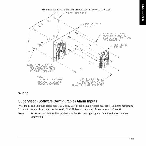
LN
L-1300-U
Mounting the SDC in the LNL-AL600ULX-4CB6 or LNL-CTX6
Wiring
Supervised (Software Configurable) Alarm InputsWire the I1 and I2 inputs across pins 1 & 2 and 3 & 4 of J15 using a twisted pair cable, 30 ohms maximum. Terminate each of these inputs with two (2) 1k (1000) ohm resistors (1% tolerance - 0.25 watt).
Note: Resistors must be installed as shown in the SDC wiring diagram if the installation requires supervision.
175

LN
L-1
300-
U
SDC input wiring
The two (2) inputs available on the SDC are software configurable alarm inputs that can be used for alarm device monitoring. Each of these inputs can be configured, via the Access Control software, as either N/O (normally open) or N/C (normally closed) in combination with either supervised or unsupervised wiring. These alarm inputs are connected using Inputs 1 and 2.
Each input that is configured as a supervised alarm must also be terminated with two (2) 1K (1000) ohm resistors (1% tolerance - 1/4 (0.25) watt. N/O and N/C alarms are terminated identically). Resistors are provided with the module.
Install the resistors as close to input device as possible. For cable length limitations, refer to Specifications.
Input Resistor Table
Alarm Zone Contact NC
Alarm Zone Contact NO
Normal 1K ± 10% 2K ± 10%
Alarm 2K ± 10% 1K ± 10%
176

LN
L-1300-U
Upstream CommunicationThe Single Reader SDC Interface Module uses Port 1 to communicate to the Intelligent System Controller.
Port 1 is a 2-wire RS-485 interface, that requires the following type of RS-485 cable: 24 AWG (minimum) twisted pair (with shields). The main run RS-485 cable should be no longer than 4000 feet [1219 m], 100 ohms maximum (Belden 9841, West Penn, or equivalent). The drop cables (to downstream devices) should be kept as short as possible, no longer than 10 feet.
The RS-485 communication is asynchronous, half-duplex, using 1 start bit, 8 data bits, 1 stop bit.
Note: RS-485 communication is supported for upstream communication only.
Fault – Line Short 0 – 50 0 – 50
Fault – Line Open 15K – ∞ 15K – ∞Fault – Foreign Voltage
50 – 7501250 – 15002500 – 15K
50 – 7501250 – 15002500 – 15K
Input Resistor Table (Continued)
Alarm Zone Contact NC
Alarm Zone Contact NO
177

LN
L-1
300-
U
Notes: The (EIA) Electronic Industries Association standard defines RS-485 as an electrical interface for multi-port communications on a bus transmission line. It allows for high-speed data transfer over extended distances (4000 feet [1219 m]). The RS-485 interface uses a balance of differential transmitter/receiver to reject common mode noise. For increased reliability over the extended distances, End-Of-Line (EOL) termination is required.
RS-485 must be terminated at both ends of the RS-485 line (bus). Terminating the line provides a more reliable communication by minimizing the signal reflection and external noise coupling. Each component provided has an on-board terminator. The installer should determine which device is at the end of the communication line.
Relay OutputsThe Single Reader SDC Interface Module contains two (2) form-C dry-contact relay outputs, Relay 1 & 2 (K1 & K2). K1 is rated at 5A 30 VDC; K2 is rated at 1A 30 VDC.
To wire the K1 and K2 outputs, use sufficiently large wires for the load to avoid voltage loss.
Transient clamping must be provided to protect the output contacts and to reduce EMI emissions. For AC-powered devices, use MOV across the load. For DC-powered devices, use a diode across the load.
Relay contact (DC strike)
178

LN
L-1300-U
Relay contact (AC strike)
SDC AUX relay wiring
179

LN
L-1
300-
U
Downstream Reader CommunicationThe Single Reader SDC Interface Module can communicate downstream with one (1) card reader. The interface is six wire that includes buzzer and LED control. The LED and buzzer are both open collector types switching (sinking) 10mA maximum.
Note: The LNL-1300-U does not support Bioscrypt readers or the LNL-CK keypad.
Use 18 AWG wire minimum and maximum length of 500 feet [150m].
Reader power: Voltage 12 VDC +/-10% (optional 5 VDC +/-5% jumper selectable, current 400 mA maximum to 50°C, derate to 300 mA for 70°C).
Reader wiring
Open Supervised Device ProtocolOpen Supervised Device Protocol (OSDP) uses bi-directional communications between readers and the reader interface, providing constant monitoring of reader health, improved control of reader operation and configuration in real-time, and additional communications capabilities over a single connection, including LCD reader display control.
180

LN
L-1300-U
Wiring for OSDP readers
Elevator ControlOnGuard hardware is capable of supporting elevator control for up to 128 floors. An elevator reader has an input/output module that controls the access to floors via an elevator.
The OnGuard software must be configured for elevator control. This can be done from System Administration by selecting the Elevator check box on the General tab in the Readers and Doors form. The reader’s type, name, port, address, and access panel can all be defined here as well.
Note: In order for this check box to be available, the access panel to which this reader module is connected must have Elevator support enabled on the Options tab.
With elevator control on the LNL-1300 reader, door strike and contact are not available, and REX (Request to EXit) is disabled.
Addresses assigned to input/output panels do not need to be consecutive. On the first panel, the inputs/outputs represent the first sixteen floors (e.g.: Input 1 = first floor, Input 2 = second floor, etc.). The second panel represents the next sixteen floors (floor 17 through 32), etc.
181

LN
L-1
300-
U
Overview of Elevator Control
External (Cabinet) TamperAn external cabinet tamper is configured by connecting a tamper device across pins 3 & 4 of J18 on the SDC. If not used, a jumper must be installed across pins 3 & 4 of J18.
Note: Power fail is not supported on the SDC; therefore no jumper is required. This is labeled in the diagram as “NOT USED.”
Intelligent System Controller
Output Control Module
Elevator Reader
(inside cab)
Input Control Module
Access Control System
Elevator Control Room
Up to 128 Outputs - eight Output Control
Modules
Up to 128 Inputs - eight Input Control
Modules
Single Reader Interface
Single Reader
Interface Module
Single Reader
Interface
Maximum: 4000 feet
(1219.2 meters)5 conductors
182

LN
L-1300-U
External tamper wiring
Note: Input status LEDs will be off when the tamper device is in closed position or the jumper is installed.
Power and CommunicationsFor its power input, the SDC requires a 12 to 24 VDC ± 10% power source for it input power.
Wire the power input with 18 AWG (minimum) twisted pair cable.
Power Source Requirements Current
DC power source Isolated, non-switching, regulated DC power
700mA for 12VDC350mA for 24VDC
183

LN
L-1
300-
U
Power source wiring
Notes: Be sure to observe polarity.
Do not use an AC transformer to directly power the Single Door SDC Interface Module.
184

LN
L-1300-U
SpecificationsThe LNL-1300-U is for use in low voltage, class 2 circuits only. These specifications are subject to change without notice.
• Primary power:
- 12 to 24 VDC + 10%- 12 VDC @ 700 mA (includes reader current) nominal- 24 VDC@ 350 mA (includes reader current) nominal- 28.7 BTU/hour
• Outputs: Form-C contacts: Relay 1 and 2 (K1 and K2): 5 A @ 30 VDC
• Inputs:
- Two (2) supervised, End of Line resistors, 1k/1k ohm, 1% 1/4 watt standard- One (1) unsupervised, dedicated for external (cabinet) tamper
• Reader Interface:
- Reader power: voltage 12 VDC +/-10% (optional 5 VDC +/-5% jumper selectable, current 400 mA maximum to 50°C, derate to 300 mA for 70°C)
- Reader LED output: open collector type switching (sinking) 10 mA each- Buzzer output: open collector type switching (sinking) 10 mA each- Reader data inputs: 2-wire RS-485, Wiegand, Clock and Data
• Upstream communication: RS-485, 2-wire. 2400 to 38400 bps
- Does not support encryption• Downstream communication:
- Does not support RS-485• Cable requirements:
- Power: 18 AWG, 1 stranded twisted pair- RS-485 24 AWG, 120 ohm impedance, stranded twisted pair with shield, 4000 feet (1219 m)
maximum- Alarm Inputs: 1 stranded twisted pair per input, 30 ohms maximum- Outputs: As required for the load- Reader data (Wiegand, Clock and Data): 18 AWG stranded, 6 conductor, 500 feet (150 m)
maximum- Reader data (RS-485): 24 AWG, 120 ohm impedance, stranded twisted pair with shield, 4000
(1,219 m) maximum• Mechanical:
185

LN
L-1
300-
U
- Dimension: 4.75 x 2.75 x 1.25 in. (121 x 70 x 32 mm)- Weight: 3.5 oz. (100 g) nominal
• Environmental:
- Temperature: -10 to +70°C (14 to 158°F) operating, -40 to +85°C (-40 to 185°F) storage- Humidity: 10% at 93°C (199°F) non-condensing operating, 10 to 95% at 85°C (185°F) non-
condensing storage• Certifications:
- FCC Part 15- FCC compliance: This equipment has been tested and found to comply with the limits for a
Class A digital device, pursuant to part 15 of the FCC Rules. These limits are designed to provide reasonable protection against harmful interference when the equipment is operated in a commercial environment. This equipment generates, uses, and can radiate radio frequency energy and, if not installed and used in accordance with the instruction manual, may cause harmful interference to radio communications.
- ETL 294, s319- UL294, UL1076- C-Tick N22193 - CE marking- RoHS- Environmental class: Indoor dry - WEEE
European Union directives: 2002/96/EC (WEEE directive): Products marked with this symbol cannot be disposed of as unsorted municipal waste in the European Union. For proper recycling, return this product to your local supplier upon the purchase of equivalent new equipment, or dispose of it at designated collection points. For more information see: www.recyclethis.info.
186

LN
L-1320
Dual Reader Interface Module LNL-1320 Series 2The Dual Reader Interface (SDRI) supports most access control card readers, keypads, or readers with keypads that use standard Wiegand Data1/Data0 or Clock/Data communications. Lock, unlock, and facility code offline access modes are supported on all readers connected to the DRI.
The DRI provides a vital link between the Intelligent System Controller (ISC) and the card reader attached to the interface. As many as 32 DRI modules can be multi-dropped using RS-485 2-wire communication, up to 4000 feet per port away from the ISC. Each DRI module is individually addressed for increased reporting capabilities with OnGuard Access Control software applications. The DRI includes eight inputs that support normally open, normally closed, supervised, and non-supervised circuits. In addition, six output relays support fail-safe or fail-secure operation.
149

LN
L-1
320
LNL-1320 Components
INP
UT
S
IN 1
IN 2
IN 3
IN 4
IN 5
IN 6
IN 7
IN 8
TMP
GND
PFL
GN
D D
AT
CL
K
BZ
A
LE
O
VO
D0
D
1G
ND
DA
T C
LK
BZA
L
EO
V
OD
0
D1 RE
ADER
2R
EADE
R 1
RS
-485
TR +
TR -
R +
R -
SG
A C OC
A C
GN O
J6
J5
J5, J 6 TE R MINA TOR
2W 4WJ 3
RS-485
U 1 OFF ONS 1
8 7
6 5
4
3 2
1
NO
C
N
C
NO
C
N
CR
LY
2
R
LY 1
NO
C
N
C
N
O
C
NC
RL
Y 4
RL
Y 3
NO
C
N
C
N
O
C
NC
RLY
6
R
LY
5
5.50 (139.7)
6.00 (152.4)
8.00
(203
.2)
0.25 (6.4)
0.50
(12
.7)
2.00
(50
.8)
2.00
(50
.8)
3.00
(76
.2)
READER INTERFACE
DIP SWITCHES
OUTPUTS
RELAY STATUS LEDs
INPUTS (1-8)
COMMUNICATION PORT, RS-485
POWER IN
TB
1T
B2
TB
3T
B4
TB
5TB
6TB
7
TB 12
TB 11
TB10
TB9
TB 8
K1
K2
K3
K4
K5
K6
K 1 K 2 K 3 K 4 K 5 K 6J 3J15
12V P T
J 14J 13
J 11
J 10
J 9
J 12
GND
A B 1 2 3 4 5 6 7 8 P FL R 1 R 2TMP STATUS LEDs
J8
J7
150

LN
L-1320
Status LEDsThe series 2 Dual Reader Interface Module board contains LEDs that can be used to verify correct installation after power up.
The A LED is turned on at the beginning of initialization. If the application program cannot be run, the A LED will flash at a rapid rate. The dual reader interface module is waiting for firmware to be downloaded.
When initialization is completed, LEDs A through R2 are briefly sequenced ON then OFF.
After the above sequence, the LEDs have the following meanings:
Input in the inactive state: OFF (briefly flashes ON every 3 seconds).
Input in the active state: ON (briefly flashes OFF every 3 seconds).
Input in a trouble state (default): Rapid Flash.
LED Purpose
A This LED is the heartbeat and online status.Offline: 1 second rate, 20% ON, Online: 1 second rate, 80% ON
B Indicates communication activity on the communication port.
1 IN1 input status
2 IN2 input status
3 IN3 input status
4 IN4 input status
5 IN5 input status
6 IN6 input status
7 IN7 input status
8 IN8 input status
TMP Cabinet tamper
PFL Power fault
151

LN
L-1
320
R1: reader port 1:• Clock/Data Mode: Flashes when data is received, either input.
• Data 0/Data 1 Mode: Flashes when data is received, either input.
• RS-485 Mode: Flashes when transmitting data.
R2: reader port 2:• Clock/Data Mode: Flashes when data is received, either input.
• Data 0/Data 1 Mode: Flashes when data is received, either input.
• RS-485 Mode: Flashes when transmitting data.
LED K1 through K6: Illuminates when output relay RLY 1 (K1) through RLY 6 (K6) is energized.
152

LN
L-1320
WiringSupervised Alarm Inputs - Standard wiring configuration is as follows (Alarm Contacts 1-4 are for Door #1, Alarm Contacts 5-8 are for Door #2):
In 1
In 2
In 3
In 4
In 5
In 6
In 7
In 8
Door 1 Door Contact
Door 1 REX
Door 1 Aux 1
Door 1 Aux 2
Door 2 Door Contact
Door 2 REX
Door 2 Aux 1
Door 2 Aux 2
DRI Alarm Input Contact Wiring
TMP
GND
PFL
Cabinet TamperPower Failure
GND
153

LN
L-1
320
Wire the IN1 - IN8 inputs using a twisted pair cable, 30 ohms maximum. Terminate each of these inputs with two (2) 1000-ohm resistors (1% tolerance - 0.25 watt) for supervised inputs.
1K, 1%
1K, 1%
1K, 1%
1K, 1%
NC
NO
NC
NO
Supervised
Unsupervised
154

LN
L-1320
Upstream Controller CommunicationThe Dual Reader Interface Module uses Port 1 to communicate to the Intelligent System Controller.
The RS-485 is asynchronous, half-duplex, using 1 start bit, 8 data bits, 1 stop bit.
TR +
TR -
SG
2W
RS-485 2-WIRE COMMUNICATIONS
T+ T- SG
Earth Ground
Wire with 24 AWG stranded twisted pair with shield
155

LN
L-1
320
Output WiringContact protection circuit must be used. The following two circuits are recommended. Locate the protection circuit as close to the load as possible (within 12 inches [30cm]), as the effectiveness of the circuit will decrease if it is located further away.
12 VDC
+ -
NC
C
NO
NO
NC
C
DIODE CURRENT RATING > 1X STRIKE CURRENTDIODE BREAK DOWN VOLTAGE > 4X STRIKE VOLTAGEFOR 12 OR 24 VDC STRIKE, DIODE 1N4002 (100V/1A) TYPICAL
-
+
DC STRIKE
ACXFMR
NC
C
NO
NO
NC
C
CLAMP VOLTAGE > 1.5 X VAC RMSFOR 24 VAC STRIKE, PANASONIC ERZ-CO7DK470 TYPICAL
AC STRIKE
156

LN
L-1320
Relay Outputs
Downstream Reader CommunicationThe Dual Reader Interface Module can communicate downstream with two (2) keypads or card readers. Wire the J1 interface using a 24 AWG (minimum) cable.
DRI Alarm Output Contact Wiring
NC
C
NO
NC
C
NO
NC
C
NO
NC
C
NO
NC
C
NO
NC
C
NO
RLY 1
RLY 2
RLY 3
RLY 4
RLY 5
RLY 6
Door 1 StrikeRelay
Door 1 Aux 1
Door 1 Aux 2
Door 2 StrikeRelay
Door 2 Aux 1
Door 2 Aux 2
VO
LEDBZRD1/CLK
D0/DAT
GND
RED (1)
BRN (4)ORG (5)WHT (3)
GRN (2)
BLK (6)
0 1
2 3
4 5
6 7
8 9
* #
157

LN
L-1
320
PowerWire the power input with an 18 AWG (minimum) twisted pair cable.
DIP SwitchesDIP switches must be configured appropriately for your system.
Device Address
Address DIP SWITCH
5: 4: 3: 2: 1:
0 off off off off off
1 off off off off ON
2 off off off ON off
3 off off off ON ON
4 off off ON off off
5 off off ON off ON
6 off off ON ON off
7 off off ON ON ON
8 off ON off off off
9 off ON off off ON
VIN
GND
+
-12 to 24 VDC
Wire with 18 AWG stranded twisted pair.
158

LN
L-1320
10 off ON off ON off
11 off ON off ON ON
12 off ON ON off off
13 off ON ON off ON
14 off ON ON ON off
15 off ON ON ON ON
16 ON off off off off
17 ON off off off ON
18 ON off off ON off
19 ON off off ON ON
20 ON off ON off off
21 ON off ON off ON
22 ON off ON ON off
23 ON off ON ON ON
24 ON ON off off off
25 ON ON off off ON
26 ON ON off ON off
27 ON ON off ON ON
Device Address (Continued)
Address DIP SWITCH
5: 4: 3: 2: 1:
159

LN
L-1
320
DIP switch 8 controls the utilization of encryption.
When DIP switch 8 is ON, communication will not be allowed unless the access panel supports downstream encryption and is configured to enable encryption to this device.
28 ON ON ON off off
29 ON ON ON off ON
30 ON ON ON ON off
31 ON ON ON ON ON
Communication Baud Rate
BAUD RATE DIP SWITCH 6: DIP SWITCH 7:
38,400 bps ON ON
19,200 bps off ON
9600 bps ON off
115,200 bps off off
PASSWORD STATUS DIP SWITCH 8:(OnGuard 2009 or later)
DIP SWITCH 8:(prior to OnGuard 2009)
Encryption is optional off Normal operation
Encryption is required ON Not allowed
Device Address (Continued)
Address DIP SWITCH
5: 4: 3: 2: 1:
160

LN
L-1320
When DIP switch 8 is off, the device will accept either encrypted or unencrypted communication. It must be off if the access panel does not support downstream encryption, or if downstream encryption is disabled for this device.
Installing Jumpers
[J5]RS-485 EOL termination : Jumper = termination . No jumper = no termination
[J2]Reader power : 12V = 24 VDC reduced to 12 VDC at reader ports .
Do not use if VIN is less than 20 VDC PT = VIN passed through to reader ports
[J3]2-wire select: Must install in 2W position.
INP
UT
S
IN 1
IN 2
IN 3
IN 4
IN 5
IN 6
IN 7
IN 8
TMP
GND
PFL
GND
D
AT
CLK
B
ZA
LEO
V
OD0
D
1G
ND
DA
T C
LK
BZ
A
LEO
V
OD
0 D
1 REA
DER
2RE
ADER
1
RS
-485
TR +
TR -
R +
R -
SG
A COC
A C
GNO
J6
J5
2W 4WJ 3
RS-485
U1OFF ON
S1
8 7
6 5
4
3
2 1
NO
C
NC
NO
C
N
CR
LY 2
R
LY 1
NO
C
NC
N
O
C
NC
RLY
4
RLY
3N
O
C
NC
N
O
C
NC
RL
Y 6
R
LY 5
TB1
TB
2T
B3
TB4
TB
5T
B6T
B7
TB12
TB11
TB 10
TB 9
TB8
K1
K2
K3
K4
K5
K6
K1 K2 K 3 K 4 K 5 K 6J3J15
12V P T
J14J13
J11
J 10
J9
J12
GND
A B 1 2 3 4 5 6 7 8 P FL R1 R2TMP
J8
J7
161

LN
L-1
320
SpecificationsThe LNL-1320 is for use in low voltage, class 2 circuits only. These specifications are subject to change without notice.
• Primary power: 12 to 24 VDC + 10%, 550mA maximum (plus reader current)
- 12 VDC @ 450mA(plus reader current) nominal- 24 VDC @ 270mA (plus reader current) nominal
• Outputs: Six outputs, Form-C, 5A @ 28 VDC resistive
• Inputs:
- Eight (8) unsupervised/supervised, standard EOL, 1k/1k ohm, 1% 1/4 watt- Two (2) unsupervised, dedicated for cabinet tamper and UPS fault monitoring
• Reader interface:
- Reader power (jumper selectable): 12 VDC + 10% regulated, 125mA maximum each reader or 12 to 24 VDC ±10% (input voltage passed through) 125mA maximum each reader
- Reader LED output: TTL compatible, high > 3V, low < 0.5V, 5mA source/sink maximum- Reader buzzer output: Open collector, 5 VDC open circuit maximum, 10mA sink maximum- Reader data inputs: TTL compatible inputs or 2-wire RS-485
• Communication: RS-485 two-wire, 9600 to 115,200 bps
• Cable requirements:
- Power: 18 AWG, 1 stranded twisted pair- RS-485: 24 AWG, 120 ohm impedance, stranded twisted pair with shield, 4000 feet (1219 m)
maximum- Alarm inputs: 1 stranded twisted pair per input, 30 ohms maximum- Outputs: As required for the load- Reader data (TTL): 6 conductors, 18 AWG stranded, 500 feet (150 m) maximum- Reader data (RS-485): 24AWG, 120 ohm impedance, stranded twisted pair with shield, 4000
feet (1219 m) maximum• Mechanical:
- Dimension: 6 x 8 x 1 in. (152 x 203 x 25 mm)- Weight: 11 oz. (312 g) nominal
• Environmental:
- Temperature: 32 to 158° F(0 to 70° C) operating, -67 to +185° F (-55 to +85° C) storage- Humidity: 0 to 95% RHNC
• Certifications:
162

LN
L-1320
- UL294 and UL1076 Listed, ULC Listed- FCC Part 15- C-Tick- CE marking- RoHS compliant- WEEE
163

LN
L-1
320
164

LN
L-1320-U
Dual Door Controller Module LNL-1320-UThe Dual Door Controller (DDC) provides a solution for interfacing to Wiegand Data1/Data0 and Magnetic Clock/Data readers or keypads (4/8 bit), and door hardware. It can accept data from a reader with clock/data, Wiegand signaling, or 2-wire RS-485, provides a tri-stated LED control and buzzer control. Six form-C relay outputs may be used for strike control or alarm signaling. Eight inputs are provided for monitoring the door contact and exit push button, and auxiliary inputs (supervised or unsupervised). Communication to the host controller and other modules is done via a 2-wire RS-485 interface. It requires 12 to 24 VDC for power.
DDC board
Installation1. Set baud rate, address, and LED control switches.
2. Install jumpers.
3. Mount the board in the enclosure.
187

LN
L-1
320-
U
Note: The LNL-CONV-U1 Universal Mounting Plate is required when installing the board into a CTX enclosure. For more information, refer to Mounting on page 197.
4. Wire the supervised alarm inputs.
5. Wire the upstream host communication.
6. Wire the relay outputs for door strike and AUX.
7. Wire the downstream interface for the keypad or card reader.
8. Wire the unsupervised alarm inputs for power fail and cabinet tamper.
9. Wire the power and communications inputs.
10. Validate proper operation on power up.
ConfigurationThe Dual Door Controller (DDC) Interface Module board contains two (2) 8-position DIP switches that are user-selectable to control addressing, baud rate, and other functions, and seven (7) jumpers used to configure your system.
188

LN
L-1320-U
Setting DIP SwitchesDDC dip switches
189

LN
L-1
320-
U
Communication Baud Rate (SW1)Configure the baud rate using SW1 switches 1-4. (Switch 5 is used for LED control. Switches 6-8 are not used.)
LED ModeSW1 switch 5 is used for LED control. It is read at boot time. If you make a change to this setting, be sure to restart.
Note: The status LEDs only function when the cabinet tamper switch is open (cabinet door is open). When the cabinet tamper switch is closed (cabinet door is closed), the status LEDs are off.
Baud rate SW1 switch for host SW1 switch for OSDP readers (Aux ports)
1: 2: 3: 4:
2400 bps off off off off
9600 bps ON off ON off
19200 bps off ON off ON
38400 bps ON ON ON ON
SW1 Switch 5 State
ON LEDs behave as the Access (LNL) series module.
off LED behavior is in Normal Mode
190

LN
L-1320-U
Device Address (SW2)Configure the board address using SW2. (Switches 6-8 are not used.)
Address SW2 switch
1: 2: 3: 4: 5:
0 off off off off off
1 ON off off off off
2 off ON off off off
3 ON ON off off off
4 off off ON off off
5 ON off ON off off
6 off ON ON off off
7 ON ON ON off off
8 off off off ON off
9 ON off off ON off
10 off ON off ON off
11 ON ON off ON off
12 off off ON ON off
13 ON off ON ON off
14 off ON ON ON off
15 ON ON ON ON off
16 off off off off ON
191

LN
L-1
320-
U
17 ON off off off ON
18 off ON off off ON
19 ON ON off off ON
20 off off ON off ON
21 ON off ON off ON
22 off ON ON off ON
23 ON ON ON off ON
24 off off off ON ON
25 ON off off ON ON
26 off ON off ON ON
27 ON ON off ON ON
28 off off ON ON ON
29 ON off ON ON ON
30 off ON ON ON ON
31 ON ON ON ON ON
Address SW2 switch
1: 2: 3: 4: 5:
192

LN
L-1320-U
Installing Jumpers
193
LN
L-1
320-
U
Host Communications
• Jumper J33 pins 1 & 2 for RS-485 communications termination. Install jumper on the last DDC unit on the communications line for proper termination of the communications bus. For more information, refer to the DDC upstream communication diagram.
Reader 1 output voltage selection:
• Jumper J12 pins 1 & 2 for +12VDC readers
• Jumper J12 pins 2 & 3 for +5VDC readers
Reader 2 output voltage selection:
• Jumper J17 pins 1 & 2 for +12VDC readers
• Jumper J17 pins 2 & 3 for +5VDC readers
Reader 1 RS-485 termination:
• Jumper J29 pins 1 & 2 for RS-485 reader communications.
Note: Do NOT install the jumper for Wiegand/Clock & Data/F2F Reader Communications.
Reader 2 RS-485 termination:
• Jumper J31 pins 1 & 2 for RS-485 reader communications.
Note: Do NOT install the jumper for Wiegand/Clock & Data/F2F Reader Communications.
Reader 1 data line pull-up voltage selection:
• Jumper J9 pins 1 & 2 for +12VDC Data Line
• Jumper J9 pins 2 & 3 for +5VDC Data Lines
Note: Not required for RS-485 communications.
Reader 2 data line pull-up voltage selection:
• Jumper J14 pins 1 & 2 for +12VDC Data Lines
• Jumper J14 pins 2 & 3 for +5VDC Data Lines
Note: Not required for RS-485 communications.
Jumpers J30 & J32 not used.
Status LED Table for Series 2 LNL-1320 ModeNote: The status LEDs only function when the cabinet tamper switch is open (cabinet door is open).
When the cabinet tamper switch is closed (cabinet door is closed), the status LEDs are off.
194

LN
L-1320-U
When switch 5 is in the ON position, the LEDs behave like the series 2 LNL-1320.
Status LED Table for Normal ModeWhen SW1 switch 5 is in the off position, the LEDs operate in Normal Mode. External tamper (cabinet tamper) must be open for Input LEDs to be on. When tamper is closed (cabinet door closed) Input LEDs will be off.
Indication LED State
Power-up ALL Off
Initialization D84 Flashing
After initialization D84 Offline: 1 second rate, 20% ONOnline: 1 second rate, 80% ON
Communications D1 ON
Indication LED State
RS-485 panel communication
D1 ON - Yellow
Reader 1 RS-485 communication
D6 ON - Yellow
Reader 2 RS-485 communication
D15 ON - Yellow
Power on D41 ON - Green
Relay 1 D44 ON - Green
Relay 2 D51 ON - Green
Relay 3 D52 ON - Green
Relay 4 D59 ON - Green
195

LN
L-1
320-
U
CPU status LED D84 possible module error conditions for LED Normal and Series 2 modes:
Relay 5 D60 ON - Green
Relay 6 D67 ON - Green
Supervised input I1-I8 D69, D70-D74, D76-D78
Active: ON - YellowInactive: ON - GreenForeign: ON - RedCut: Flashing - GreenShort: Flashing - RedGround: Flashing - Yellow
Unsupervised I1-I8 D69, D70-D74, D76-D78
Closed ON - Red,Open - Off
CPU status D84 Offline: 1 second rate, 20% ONOnline: 1 second rate, 80% ONFlashing Green - Badge Read
External (cabinet) tamper D85 Open ON - Red
Power fail D87 ON - Red
Error condition Flashing pattern
Description
No valid application firmware
3 Red, 2 Green
The module is not operational. Firmware must be loaded using a console, e.g. HyperTerminal with Xmodem.
Boot loader waiting on firmware file
3 Red, 1 Green
Console boot loader is waiting on start of firmware file.
Boot loader loading firmware file
2 Red, 2 Green
Console boot loader is loading a firmware file.
Invalid EFL file 1 Red, 2 Green
The EFL specified to be loaded using the console loader is not a valid EFL file.
Indication LED State
196

LN
L-1320-U
MountingThe DDC can be mounted in the LNL-AL400ULX or LNL-AL600ULX-4CB6 and the LNL-CTX or LNL-CTX6 enclosure using the Universal Mounting Plate (UMP) LNL-CONV-U1
Invalid Xmodem packet 1 Red, 1 Green
The console loader received an invalid Xmodem packet and terminated the firmware download operation.
Invalid Application firmware for module CPU
3 Red, 0 Green
The module is not operational. Application firmware loaded on the module will not run properly. Requires new firmware be loaded using the console boot loader or the module must be returned for repair.
Invalid Boot firmware for module CPU
2 Red, 3 Green
The module is not operational. Boot loader firmware loaded on the module will not run properly. The module must be returned for repair.
Firmware update failed 1 Red, 3 Green
Firmware update operation was unsuccessful. Retry and if it fails continuously, load a different firmware file.
No valid primary firmware copy
3 Green, 2 Red
The firmware flash contains 2 copies of the application firmware. The primary copy is not valid so the backup copy will be loaded into the primary copy and executed.
No valid backup firmware copy
3 Green, 1 Red
The firmware flash contains 2 copies of the application firmware. The backup copy is not valid so the primary copy will be loaded into the backup copy.
No valid manufacturing parameters
3 Green, 0 Red
The manufacturing parameters which include the serial number, etc. are invalid. The module must be returned for repair.
Error condition Flashing pattern
Description
197

LN
L-1
320-
U
Mounting the DDC in the LNL-AL400ULX and LNL-CTX
198

LN
L-1320-U
Mounting the DDC in the LNL-AL600ULX-4CB6 or LNL-CTX6
WiringWire inputs I1 through I8 (J19 - J22) using a twisted pair cable, 30 ohms maximum, 24 AWG minimum.
199

LN
L-1
320-
U
Supervised (Software Configurable) Alarm InputsDDC input wiring
Note: See the Input Resistor Table for termination resistor values.
The eight (8) inputs that are available on the DDC are software configurable alarm inputs that can be used for alarm device monitoring. Each of these inputs can be configured, via the Access Control software, as either N/O (normally open) or N/C (normally closed) in combination with either supervised or unsupervised wiring. These alarm inputs are connected using Inputs 1 - 8. Inputs 1 and 6 are used for the door contacts, inputs 2 and 5 are used for request to exit switches, and inputs 3, 4, 7, and 8 are available for auxiliary inputs points.
Each input that is configured as a supervised alarm must be terminated with two (2) 1K (1000) ohm resistors (1% tolerance - 1/4 (0.25) watt. N/O and N/C alarms are terminated identically.)
200

LN
L-1320-U
Install the resistors as close to input device as possible. For cable length limitations, refer to Specifications.
Upstream CommunicationThe DDC uses Port 1 to communicate to the Intelligent System Controller.
Port 1 is a 2-wire RS-485 interface, that requires the following type of RS-485 cable: 24 AWG (minimum) twisted pair (with shields). The main run RS-485 cable should be no longer than 4000 feet [1219 m], 100 ohms maximum (Belden 9841, West Penn, or equivalent). The drop cables (to downstream devices) should be kept as short as possible, no longer than 10 feet [3.048 m].
The RS-485 communication is asynchronous, half-duplex, using 1 start bit, 8 data bits, 1 stop bit
Note: RS-485 communication is supported for upstream communication only.
Input Resistor Table
Alarm Zone Contact NC
Alarm Zone Contact NO
Normal 1K ± 10% 2K ± 10%
Alarm 2K ± 10% 1K ± 10%
Fault – Line Short 0 – 50 0 – 50
Fault – Line Open 15K – ∞ 15K – ∞Fault – Foreign Voltage
50 – 7501250 – 15002500 – 15K
50 – 7501250 – 15002500 – 15K
201

LN
L-1
320-
U
DDC upstream communication
To enable RS-485 termination, install jumper on pin header J33 (on the last unit on the communications line).
Notes: The (EIA) Electronic Industries Association standard defines RS-485 as an electrical interface for multi-port communications on a bus transmission line. It allows for high-speed data transfer over extended distances (4000 feet [1219m]). The RS-485 interface uses a balance of differential transmitter/receiver to reject common mode noise. For increased reliability over the extended distances, End-Of-Line (EOL) termination is required.
RS-485 must be terminated at both ends of the RS-485 line (bus). Terminating the line provides a more reliable communication by minimizing the signal reflection and external noise coupling. Each component provided has an on-board terminator. The installer should determine which device is at the end of the communication line.
Control Output WiringContact protection circuit must be used. The following two (2) circuits are recommended. Locate the protection circuit as close to the load as possible (within 12 inches [30cm]), as the effectiveness of the circuit will decrease if it is located farther away.
202

LN
L-1320-U
Relay OutputsRelay contact (DC strike)
Relay contact (AC strike)
203

LN
L-1
320-
U
DDC AUX relay wiring
Downstream Reader CommunicationThe DDC can communicate to two (2) card readers. The interface is six-wire that includes buzzer and LED control. The LED and buzzer are both open collector type switching (sinking) 10 mA maximum.
Note: The LNL-1320-U does not support Bioscrypt readers or the LNL-CK keypad.
Wire using 18 AWG wire minimum and maximum length of 500 feet [152.4m].
Reader power: Voltage 12 VDC +/-10% (optional 5 VDC +/-5% jumper selectable, current 400 mA maximum to 50°C, derate to 300 mA for 70°C.
204

LN
L-1320-U
DDC reader wiring
Open Supervised Device ProtocolOpen Supervised Device Protocol (OSDP) uses bi-directional communications between readers and the reader interface, providing constant monitoring of reader health, improved control of reader operation and configuration in real-time, and additional communications capabilities over a single connection, including LCD reader display control.
205
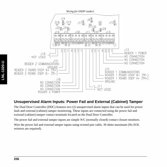
LN
L-1
320-
U
Wiring for OSDP readers
Unsupervised Alarm Inputs: Power Fail and External (Cabinet) TamperThe Dual Door Controller (DDC) features two (2) unsupervised alarm inputs that can be used for power fault and external (cabinet) tamper monitoring. These inputs are connected using the power fail and external (cabinet) tamper contact terminals located on the Dual Door Controller.
The power fail and external tamper inputs are simple N/C (normally closed) contact closure monitors.
Wire the power fail and external tamper inputs using twisted pair cable, 30 ohms maximum (No EOL resistors are required).
206

LN
L-1320-U
Note: Input status LEDs will be off when the tamper device is in the closed position or the jumper is installed
External (cabinet) tamper: Configure by connecting a tamper device across pins 3 & 4 of J27 on the DDC. If not used, a jumper must be installed across pins 3 & 4 of J27.
Power fail: Configure by connecting pins 1 & 6 of J27 to power fail device. If not used, a jumper must be installed across pins 1 & 6 of J27.
Power and CommunicationsThe Dual Door Controller requires a 12 to 24 VDC ± 10% power source for its input power.
Wire the Power In input with 18 AWG (minimum) twisted pair cable.
Note: Be sure to observe polarity.
Power Source Requirements Current
DC power source Isolated, non-switching, regulated DC power
1200mA for 12VDC600mA for 24VDC
207

LN
L-1
320-
U
Power source wiring
208

LN
L-1320-U
SpecificationsThe LNL-1320-U is for connection to low voltage, class 2 power-limited circuits only. These specifications are subject to change without notice.
• Primary power: 12 to 24 VDC + 10%
- 12 VDC @ 1200 mA (includes reader current) nominal- 24 VDC @ 600 mA (includes reader current) nominal- 49.1 BTU/hour
• Outputs: Form-C contacts, Relays 1-6 (K1-K6), 5 A @ 30 VDC
• Inputs:
- Eight (8) supervised, End of Line resistors, 1k/1k ohm, 1% 1/4 watt standard- One (1) unsupervised, dedicated external (cabinet) tamper- One (1) unsupervised, AC power fail
• Reader interface:
- Reader power (per reader): voltage 12 VDC +/-10% (optional 5 VDC +/-5% jumper selectable, current 400 mA maximum to 50°C, derate to 300 mA for 70°C)
- Reader LED output: open collector type switching (sinking) 10 mA each- Reader buzzer output: open collector type switching (sinking) 10 mA each- Reader data inputs: 2-wire RS-485, Wiegand Data1/Data0, Clock and Data
• Upstream communication: RS-485, 2-wire, 2400 to 38400 bps
- Does not support encryption• Downstream communication:
- Does not support RS-485• Cable requirements:
- Power: 18 AWG, 1 stranded twisted pair- RS-485: 24 AWG, 120 ohm impedance, stranded twisted pair with shield, 4000 feet (1219 m)
maximum- Alarm inputs: 1 stranded twisted pair per input, 30 ohms maximum- Outputs: As required for the load- Reader data (Wiegand, Clock and Data): 6 conductors, 18 AWG stranded, 500 feet (152.4 m)
maximum- Reader data (RS-485): 24 AWG, 120 ohm impedance, stranded twisted pair with shield, 4000
feet (1219 m) maximum• Mechanical:
209

LN
L-1
320-
U
- Dimension: 5 x 8 x 1.25 in. (127 x 203 x 32 mm)- Weight: 7.3 oz. (207 g) nominal
• Environmental:
- Temperature: -10 to +70°C (14 to 158°F) operating, -40 to +85°C (-40 to 185°F) storage- Humidity: 10% at 93°C (199°F) non-condensing operating, 10 to 95% at 85°C (185°F) non-
condensing storage• Certifications:
- FCC Part 15- FCC compliance: This equipment has been tested and found to comply with the limits for a
Class A digital device, pursuant to part 15 of the FCC Rules. These limits are designed to provide reasonable protection against harmful interference when the equipment is operated in a commercial environment. This equipment generates, uses, and can radiate radio frequency energy and, if not installed and used in accordance with the instruction manual, may cause harmful interference to radio communications.
- ETL 294, s319- UL294, 1076- C-Tick N22193- CE marking- RoHS- Environmental class: Indoor dry - WEEE
European Union directives: 2002/96/EC (WEEE directive): Products marked with this symbol cannot be disposed of as unsorted municipal waste in the European Union. For proper recycling, return this product to your local supplier upon the purchase of equivalent new equipment, or dispose of it at designated collection points. For more information see: www.recyclethis.info.
210

LN
L-8000
Star Multiplexer LNL-8000The Star Multiplexer was designed to implement star topology on a single downstream port (ports 2 through 5 of any of the Intelligent System Controllers (ISC) or on any host communication port of any OnGuard server) to eight RS-485 (2-wire) ports or four RS-485 (4-wire) channels. It allows conversion of communication protocol, and provides connection with alternate communication devices to extend effective distances.
The host interface can be either RS-232 or RS-485 (2-wire) communication. The Star Multiplexer interfaces upstream with the ISC, and downstream with one or many Lenel RS-485 products on each downstream port (ports 2-9). A maximum of eight devices are allowed per downstream port.
LNL-8000 Components
TR+
TR-
GND
TR+
TR-
GND
TR+
TR-
GND
TR+
TR-
GND
0.50
(13)
2.00
(51)
5.00
(127
)
5 .50 (140)
6.00 ( 152)
TB7
TB8
TB9
TB10
POR
T 6
POR
T 7
PO
RT
8P
ORT
9
TR+
TR-
GND
TR+
TR-
GND
TR+
TR-
GND
TR+
TR-
GND
TB3
TB4
TB5
TB6
PO
RT 2
PORT
3PO
RT
4PO
RT
5
POR
T 1
J6J1
232
485
JP2
232
485
JP7
JP5
TR +TXDTR -RXD
GNDT B2
JP17
A 1 2 3 4 5 6 7 8 9
+ DC
NC
GNDT B1
JP15
JP13
JP9
JP8
JP3
JP14
JP12JP11
JP4
JP10
JP161
2 3
4
2.00
(51)
U12
U9
211

LN
L-8
000
Upstream Controller CommunicationThe Star Multiplexer can communicate to the Intelligent System Controller by one of four downstream ports, either by RS-485 (2-wire) communications or RS-232 to RS-485 converters
RS-232 2-WIRE
RxDTxD
TR+TXD
TR-RXD
GND
GND
Earth Ground
Wire with 24 AWG stranded
RS-485 2-WIRE
TR+TXD
TR-RXD
GND
GNDTR-TR+
Earth Ground
Wire with 24 AWG stranded twisted pair(s) with shield
212

LN
L-8000
Downstream CommunicationsThe Star Multiplexer topology is capable of eight different downstream directions in RS-485 (2-wire) communications (using Belden 9841 or equivalent) or four different downstream directions with RS-485 (4-wire) communications (using Belden 9842 or equivalent).
Each leg of the star, in either configuration, has a maximum wire distance of 4000 feet. Each leg supports up to eight (8) Lenel hardware RS-485 devices in many configurations.
PowerThe Star Multiplexer accepts a 12 VDC ± 15% power source for its power input. The power source should be located as close to the Star Multiplexer as possible. Wire the power input with an 18 AWG (minimum) twisted pair cable.
When using a 12 VDC power source, be sure to observe polarity.
R S-485 2-W IR E
TR +
TR -
G N D
TR+ TR- G ND
W ire w ith 24 AW G stranded tw isted pair(s) w ith shie ld
RS-485 4-W IRE
TR+
TR-
G N D
TR+
TR-
G N D
R+ R- T+ T- SG
Por
ts 2
,4,6
,8R
EC
EIV
E O
NLY
Por
ts 3
,5,7
,9T
RA
NS
MIT
&
RE
CE
IVE
W ire w ith 24 AW G stranded tw isted pair(s) w ith shield
213

LN
L-8
000
Wiring and Termination
To field devices
Star Multiplexer
Star Multiplexer
Star Multiplexer
Star Multiplexer
Intelligent System Controller
Port 3 Port 2
To field devices To field devices To field devices
Note: Examples common across all ports
Remove all terminators.
T indicates termination
Port 1 Port 1 Port 1 Port 1
Ports 2-9 Ports 2-9 Ports 2-9 Ports 2-9
214

LN
L-8000
Star Multiplexer
Star Multiplexer
Intelligent System Controller
Port 2/3
To field devices To field devices To field devices
Star Multiplexer
Star Multiplexer
To field devices
T
T
Note: Examples common across all ports
Only terminate the last units of the multi-drop line.
T indicates termination
Port 1 Port 1 Port 1
Port 1
Ports 2-9 Ports 2-9 Ports 2-9
Ports 2-9
215

LN
L-8
000
DIP SwitchesThe communication speed is determined by the speed at which the Intelligent System Controller is communicating to the downstream devices.
Currently, OnGuard only supports 38400 bps. Set the communication speed DIP switches in the default position of 38400 bps.
When connecting the star multiplexer directly to a host computer for multi-drop configuration, the DIP switch settings should be set to all ON - this setting is 38400 BPS Fast.
S1 S2 S3 S4 Speed
OFF ON OFF OFF 2400 bps
ON ON OFF OFF 4800 bps
OFF OFF ON OFF 9600 bps
ON OFF ON OFF 19200/38400 bps
216

LN
L-8000
Installing JumpersThe jumpers must be configured appropriately for your system.
TR+
TR-
GND
TR+
TR-
GND
TR+
TR-
GND
TR+
TR-
GND
TB
7T
B8T
B9TB
10
PO
RT
6
PO
RT
7
PO
RT
8
PO
RT
9
TR+
TR-
GND
TR+
TR-
GND
TR+
TR-
GND
TR+
TR-
GND
TB
3T
B4
TB5
TB
6
PO
RT
2
PO
RT
3
PO
RT
4
PO
RT
5
PO
RT
1
JP6
JP1
232
485
JP2
232
485
JP7
JP5
TR +TXDTR -RXDGND
TB2
JP17
A 1 2 3 4 5 6 7 8 9
+DC
NC
GNDTB1
JP15
JP13
JP9
JP8
JP3
JP14
JP12JP11
JP4
JP10
JP161 2
3
4
U12
U9
[JP1, JP6, JP5, JP7]Control for Port 1, RS-232 or RS-485
[JP2]OFF: Port 1 RS-485 EOL termination is not onON: Port 1 RS-485 EOL termination is on
[JP11, JP4, JP10, JP16]Control for Ports 2, 4, 6, 8, respectively.OFF: Port is receive only for 4-wire RS-485ON: Port is (2-wire) RS-485
[JP12, JP14, JP3, JP8, JP9, JP13, JP15, JP17]RS-485 Termination Status for ports 2-9, respectively. OFF: Not terminatedON: terminated
217

LN
L-8
000
SpecificationsThe Star Multiplexer is for use in low voltage, class 2 circuits only. These specifications are subject to change without notice.
• Primary Power:
- DC input: 12 VDC ± 15%. 250 mA• Interfaces:
- Port 1: RS-232/RS-485, selectable- Ports 3, 5, 7, 9: RS-485, Transmit/Receive- Ports 2, 4, 6, 8: RS-485, Transmit/Receive or Receive Only
• Wire Requirements:
- Power: 1 stranded twisted pair, 18 AWG- RS-485:24 AWG stranded twisted pair(s) with shield, 4000 feet (1219 m) maximum- RS-232: 24 AWG stranded, 50 feet (15 m) maximum
• Environmental:
- Temperature:0 to 70°C, operating, -55 to +85°C storage- Humidity: 0 to 95% RHNC
• Mechanical:
- Dimensions: 5 x 6 x 1 in. (127 x 152 x 25 mm)- Weight: 4 oz. (114 gm) nominal
• Certifications:
- UL294 and UL1076 Listed, ULC Listed- FCC Part 15- CE marking- RoHS compliant- WEEE
218

Len
elPro
x
LenelProx ReadersLenelProx readers are radio-frequency proximity readers (with or without integrated keypads). OnGuard currently supports the following models:
• LPMM-6800
• LPSP-6820
• LPKP-6840 and BT-LPKP-NDK
• LPSR-2400
• LPRKP-4600
• LPMR-1824 and LPMR-1824 MC
• LPLR-911
219

Len
elP
rox
General WiringThe following diagrams address general wiring for the LenelProx readers. For specific instructions regarding wiring, installation, and configuration, consult the Hardware Installation Guide.
Example wiring: the LPSP-6820 and the LNL-1300
LENELBrown
Yellow
White
Green
Red
Black
VO
LED
BZR
CLK/D1
DATA/D0
GND
LenelProx LPSP-6820
Single Reader Interface Module
TYPICAL SOFTWARE SETTINGS
1. Reader Type = WIEGAND/PROX2. Keypad = NO KEYPAD3. LED Mode = 1-WIRE LED CONTROL
220

Len
elPro
x
For the Dual Reader Interface Module, make sure that jumper J2 is set to unregulated power mode. This will allow the maximum amount of current for the readers.
Example wiring: the LPSP-6820 and the LNL-1320
LENEL
VO
LED
BZR
CLK/D1
DATA/D0
GND
Brown
Yellow
White
Green
Red
Black
Dual Reader Interface Module
TYPICAL SOFTWARE SETTINGS
1. Reader Type = WIEGAND/PROX2. Keypad = NO KEYPAD3. LED Mode = 1-WIRE LED CONTROL
221

Len
elP
rox
222


Len121PittTel ww
el Systems International, Inc.2 Pittsford-Victor Roadsford, New York 14534 USA866.788.5095 Fax 585.248.9185w.lenel.com