field evaluation of underground storage tank system · pdf filewinston h. hickox secretary for...
TRANSCRIPT

Winston H. HickoxSecretary for
EnvironmentalProtection
Gray DavisGovernor
FIELD EVALUATION OFUNDERGROUND STORAGE TANK SYSTEM
LEAK DETECTION SENSORS
- Appendices -
August 2002
State Water Resources Control BoardUnderground Storage Tank Program
P.O. Box 944212Sacramento, CA 94244
www.swrcb.ca.gov/cwphome/ust/

TABLE OF CONTENTS
APPENDIX ISummary of Phase I Testing (Veeder-Root Discriminating Sensors)
APPENDIX IIWorkplan for the Field Evaluation
APPENDIX IIILocation of Facilities Involved in the Field Evaluation
APPENDIX IVField Data Collection Forms
APPENDIX VSensor Survey Distribution Letter, Survey Form, Results, and Comments
APPENDIX VIField Data
APPENDIX VIIDiscussion of Point Liquid and Polymer Strip Discriminating Sensors

APPENDIX ISummary of Phase I Testing (Veeder-Root Discriminating Sensors)

November, 2000
Appendix I, Phase I Testing Summary Page 1 of 9
Figure I - A typical multi-element discriminating sensorwith float switches and a product solubility element.
Phase I Testing Summary(Field Evaluation of Veeder-Root Discriminating Sensors)
IntroductionSensors are used in a variety of places within a UST system to detect a release of product. Fordouble-wall systems, they are either located inside the secondary containment (sumps and underdispenser pans) or in the space between the primary and secondary containment of the tank orpiping, known as the interstitial space. Field experience has shown that due to numerous design,installation, and maintenance issues these areas are often not kept clean of water intrusion orexcessive condensation. This has led the industry to introduce sensors that are capable ofdifferentiating between water and hydrocarbons. These sensors are referred to as “discriminatingsensors.”
Discriminating sensors can provide distinct alarms for water or product. Some even offerdistinct alarms for low and high levels of water. Depending on how the control panel isprogrammed, a product or water (low or high level) detection can activate a warning, alarm, orpump shutdown. Typically, sensors are programmed to provide a warning when water isdetected, which still allows the UST system to operate. Product detection is typicallyprogrammed to activate a fuel alarm, and may also automatically shut down the pump.
There are two basic approaches to discriminating sensors, as described in the followingparagraphs. One approach to discriminating sensors is to combine two or more sensing elementsinto a single unit (See Figure I). This approach is well suited for sumps where surface water isprone to leak in, presenting the possibility of product floating on water. Sensing elements (mostoften a float switch) are used to detect low and high liquid levels. If the level rises above apreset point, the sensor notifies the operator by activating an alarm or warning message on acontrol panel. A hydrocarbon-sensing element (such as a product permeability sensor) is alsoincorporated to detect the presence of product. The combination of these multiple sensingelements into a single unit makes a discriminating sensor able to determine the presence of waterversus hydrocarbons. There are several combinations of detection mechanisms that may beincorporated in a single unit to produce a discriminating sensor.

November, 2000
Appendix I, Phase I Testing Summary Page 2 of 9
The second type of discriminating sensor uses only one detection mechanism, but is able todiscern between product and other liquids based on some specific property of the liquid. Someadsistor, capacitance change, electrical conductivity, fiber optic chemical, and thermalconductivity sensors are sophisticated enough to distinguish between product and water.
Purpose of the ProjectThis report is based on testing performed only on discriminating sensors manufactured byVeeder-Root, as they are the most prevalent in California. We initiated a field study ofdiscriminating sensors in response to local agency concerns that some of these sensors did notappear to operate properly when annual maintenance certification and inspections wereconducted. Particular items of concern brought to our attention by local agency inspectors were:
• The inability of discriminating sensors to detect a layer of hydrocarbon-based product (i.e.gasoline) floating on top of water and to properly distinguish between water and product;
• The inability of polymer-based hydrocarbon detecting elements to alarm in a reasonableamount of time; and
• The inability of polymer-based hydrocarbon detecting elements to return to effectiveoperation (recover) after exposure to hydrocarbons.
While this project was initially designed to address the aforementioned local agency concerns,we enlisted the help of discriminating sensor manufacturers and local agency inspectors toexpand the scope of the study. The scope of the study included:
• Evaluating the functionality of discriminating sensors used in California (in response tothe above listed concerns of local agency inspectors);
• Checking the adequacy of field-testing procedures for discriminating sensors (or workwith manufacturers to develop field-testing procedures if they are not already available);
• Determining if discriminating sensors in the field perform consistently with thespecifications outlined in their third-party evaluations; and
• Determining if the third-party evaluation protocol currently used is suitable for the sensortypes tested using that protocol.
Coordination of the Field TestingSince the focus of the testing was on the performance of sensors in the field, it was necessary toconduct testing at operating facilities where the sensors are installed. Three local agenciesrepresenting a cross section of California’s UST population local regulatory governmentsvolunteered to assist with this project. The City of Santa Ana, City of Santa Monica, and City ofOakland helped us to identify facilities within their jurisdictions that were using Veeder-Rootdiscriminating sensors. In order to minimize the impact on owners, operators, and localagencies, we scheduled our field testing to coincide with the required annual inspections. Themaintenance contractor performed the testing for the sensors while completing all the otherscheduled annual certification work. Manufacturer’s representatives were on hand to observethe testing, assist with the advanced setup and diagnostic features of the sensor control panel, andto answer technical questions.
Testing ProcedureIn order to test the sensors during this evaluation, Veeder-Root prepared a draft testingprocedure. We reviewed and provided comments on the draft test procedures, which were then

November, 2000
Appendix I, Phase I Testing Summary Page 3 of 9
modified by Veeder-Root and re-submitted as a second draft. The second draft was the testingprocedure used in our field evaluation. Modifications were made throughout the study, asdeemed necessary by our staff on site. Modifications were included to minimize stationdowntime, and to test possible improvements to the protocol (such as the cleansing of sensors inwhite gas1 to accelerate recovery of polymer strips.)
The basic test procedure was to immerse the discriminating sensor in fuel, water, or a fuel/watermixture to see if it alarmed appropriately (e.g., water and/or fuel). We modified the procedureby using a stopwatch to determine the length of time between sensor immersion and alarm, andthe length of time for the sensor to recover after being removed from the liquid. We also notedthe type and the depth of the liquid in which a sensor was immersed, as well as the type of alarm(fuel, water, or both water and fuel) the sensor registered.
Test procedures varied slightly between sensor models, due to differences in detectionmechanisms. Veeder-Root’s discriminating sensors can be classified in two general familiesbased upon their fuel-sensing mechanisms: Ultrasonic sensors (model 794380-341), and PolymerStrip Sensors (all other models tested). Table I lists the Veeder-Root discriminating sensorstested in this study, including the mechanisms each sensor model uses to determine the presenceof liquid and/or fuel, and the testing procedure used in our study.
TABLE I - Veeder-Root’s Discriminating Sensors
ModelNumber
Application VR TestProcedure
Water SensingMechanism
Fuel Sensing Mechanism
794380-320 Dispenser Pan A Ultrasonic Polymer Strip794380-350 Sump (Pump or Piping) A Ultrasonic Polymer Strip794380-322 Dispenser Pan A Float Switch Polymer Strip794380-352 Sump (Pump or Piping) A Float Switch Polymer Strip794380-360 Fiber Trench A Ultrasonic Polymer Strip794380-361 Fiber Trench A Ultrasonic Polymer Strip794380-362 Fiber Trench A Ultrasonic Polymer Strip794380-341 Interstitial B Ultrasonic Capacitance Change
Data CollectionCity of Santa AnaSWRCB staff, local agency inspectors, maintenance contractors, and Veeder-Rootrepresentatives collected data for this project. Data collection began in Santa Ana in August2000, where the local agency inspector, maintenance contractor, Veeder-Root representativeswere present at each testing site. SWRCB staff was present at some of the Santa Ana sites.Veeder-Root representatives recorded the test data in Santa Ana. This data was forwarded to usfor analysis. (See Table II for a summary of this data.)
1 Since the time of testing we have heard from other manufacturers of polymer strip sensors that this practice,although common among service technicians, may have an adverse effect on the polymer strip sensor’s continuedfunctionality. SWRCB staff does not recommend cleansing sensors with white gas unless specifically instructed todo so by the sensor manufacturer.

November, 2000
Appendix I, Phase I Testing Summary Page 4 of 9
SWRCB staff did not always witness testing in Santa Ana. Additionally, we were still refiningthe scope of data to be collected, testing procedures, and protocol for data collection. For thesereasons, results of testing in Santa Ana were usually considered only when making generalobservations and conclusions in this report, not in making any specific calculations. Anexception to this is test data for model 794380-341 sensors. Santa Ana test data for this modelhas been included in the calculations of this report, since the sample size in Santa Monica andOakland was so small. The local agency inspector present at all Santa Ana sites furnished uswith his reports on the sites equipped with model 794380-341 sensors, and this data was used incalculating pass/fail rates for that model. City of Oakland and City of Santa MonicaTesting was conducted in Oakland and Santa Monica in October and November 2000. Localagency inspectors, Veeder-Root personnel, service technicians, and SWRCB staff were presentat all facilities tested. SWRCB staff recorded all test data. Upon completion of testing, the datacollected from Oakland and Santa Monica was compiled in a data table, which is summarized inTable III.
Table II - Summary of Veeder-Root Test Data from Santa Ana*Dates of Testing August 21st–25th, 2000
Number of Facilities Tested 8Number of Sensors Tested (model 794380-208) = 18
(model 794380-320) = 3(model 794380-341) = 13(model 794380-350) = 26(model 794380-352) = 5(model 794380-362) = 1(model 794380-40x) = 10
Total Number of Sensors Tested 76*Detailed test information not available for Santa Ana facilities
Table III - Summary of Test Data from Oakland and Santa MonicaNumber of Facilities Tested 18Number of Sensors Tested (model 794380-320) = 2
(model 794380-322) = 1(model 794380-341) = 6(model 794380-350) = 8
(model 794380-352) = 49(model 794380-360) = 1
Total Number of Sensors Tested 67Pass/Fail Data for Model 794380-341 4 passes, 2 failures
Range of Response Times in Fuel and Fuel/Water Mix (794380-350) 3:26 to 42:50 (min:sec)Range of Recovery Times in Fuel and Fuel/Water Mix (794380-350) 19:49 to 70:40 (min:sec)
Range of Response Times in Water (794380-352) 2 to 18 secondsAverage Response Time in Water (794380-352) 8 seconds
Range of Response Times in Fuel and Fuel/Water Mix (794380-352) 4:59 to 12:10 (min:sec)Average Response Time in Fuel and Fuel/Water Mix (794380-352) 7 minutes, 15 seconds
Range of Recovery Times in Fuel and Fuel/Water Mix (794380-352) 0:27 to 52:29 (min:sec)Average Recovery Time in Fuel and Fuel/Water Mix (794380-352) 17 minutes, 26 seconds

November, 2000
Appendix I, Phase I Testing Summary Page 5 of 9
DiscussionSince the operating mechanism and testing procedure of the Veeder-Root model 794380-341sensor are different than all the other sensors in our study, it is reasonable to divide the“discussion” section into two parts: one part for the 794380-341 (ultrasonic mechanism), and onefor all of the other sensors in our study (polymer-strip mechanism).
Ultrasonic Mechanism (Veeder-Root Model 794380-341)Our testing showed the 794380-341 interstitial fiberglass tank sensor performed unsatisfactorily.Eleven of 20 model 794380-341 sensors failed when tested in the field2. Usually, the sensorsdetected the presence of liquid, but were unable to discriminate between fuel and water. Veeder-Root determined the failures are due to a faulty solder joint within the sensor, and is planning tomake design changes to eliminate the problem. Since the sensor cannot reliably discriminatebetween fuel and water, Veeder-Root intends to reclassify the current 794380-341 sensor as non-discriminating3.
When testing the 794380-341 sensors in Santa Ana, we observed that they often came out of thetanks wet. The moisture was a clear, odorless and somewhat gooey film. When the film dried, itbecame milky white4. There appeared to be moisture in the interstitial spaces of the tanks thesesensors are monitoring, but not enough to activate an alarm. Follow-up information from SantaAna indicates that these sensors had to be cleaned before they would alarm properly when tested,and that this is a common occurrence observed by inspectors during routine sensor fieldcertifications.
Polymer-Strip Mechanism (Veeder-Root Models 794380-320, 794380-322, 794380-350,794380-352, 794380-360, 794380-361, and 794380-362)The polymer-strip discriminating sensors consist of three separate sensing elements. The lowand high liquid detectors are float switches or ultrasonic sensors depending on the model. Theproduct-sensing element is a polymer strip that absorbs hydrocarbons. The strip is imbeddedwith small particles of conductive material (See Figure II). As the strip absorbs hydrocarbons,the material expands and the strip becomes less conductive (e.g. the resistance rises). When theresistance reaches a certain level (for Veeder-Root sensors this is set at approximately 250 kΩ to500 kΩ) an alarm is activated.
2 Includes data supplied by the local agency inspector present at Santa Ana test sites.3 Veeder-Root has completed reclassification of the model 794380-341 sensor since this summary was originallyprepared.4 The local agency inspector present at these facilities was concerned that the liquid may include resin or adhesiveused in construction of the fiberglass tanks where these sensors are installed.
Figure II – Polymer strip used in discriminating sensors

November, 2000
Appendix I, Phase I Testing Summary Page 6 of 9
The low and high-level liquid sensors proved to be generally effective. They typically activateda liquid alarm in less than the third-party specified time. On the few occasions that a sensor didnot respond properly, the problem was usually diagnosed as faulty wiring or improperprogramming of the console and not a design problem.
While our field-testing showed the low and high level liquid sensors to be effective, severalissues concerning the polymer strip were raised which may be cause for concern and furtherinvestigation. Other issues, such as control panel configuration and testing protocols, were alsobrought to light in the course of field-testing. The following paragraphs discuss these concernsin detail.
1. Response and recovery times of the polymer strip element when exposed to fuel weresometimes excessive, and not always consistent with third-party claims. Primary concernsinclude the length and variation of response and recovery times, as discussed below:
(a) Length of Response Times The fuel alarm is activated only after enough fuel has permeated the polymer strip toraise its electrical resistance to a value of 250 kΣ-500 kΣ. The time required to reach thenecessary electrical resistance varied from 5 to 12 minutes, with an average of just above7 minutes. Typically the resistance in the strip did not change appreciably for severalminutes. In the event of a catastrophic leak, this response time could lead to largeamounts of fuel in the dispenser pan or containment sump. As the liquid level reachesthe high-level liquid sensor a high level water alarm will sound, but it could still be manyminutes before the polymer strip reacts to the fuel and activates a fuel alarm. This wouldbe a major concern if the system is not configured for turbine shutdown when the highlevel water alarm is activated.
(b) Variation of Response Times With the wide variation in response times between sensors of the same model tested inthe same product, it is difficult to say exactly how long a polymer-strip sensor shouldtypically take to alarm once exposed to fuel. This makes it difficult to establish field-testing guidelines, or to determine if a sensor is actually non-functional or just slow torespond.
(c) Length of Recovery Times Recovery times often exceeded the third-party value of 17.17 minutes. Values rangedfrom under 1 minute to over 52 minutes, with an average of more than 17 minutes. Likea sponge in water, the strip swells when exposed to fuel. It must completely dry out andreturn to its original shape in order to come out of alarm. This can take quite awhile,depending on how saturated the strip is and how volatile the liquid is. In the interest oftime, our test procedure called for a minimum amount of fuel, and for the sensor to beremoved from fuel as soon as it alarmed. We even experimented with removing thesensor from fuel before it had alarmed in hopes of decreasing recovery times. Even so,the recovery times were high. Although the test protocol used in this study did notinclude long-term immersion of sensors in fuel, it is reasonable to believe that sensorsimmersed in fuel for extended periods of time (as would be the case in the event of anactual leak) would take even longer to recover, or may not recover at all.
November, 2000
Appendix I, Phase I Testing Summary Page 7 of 9
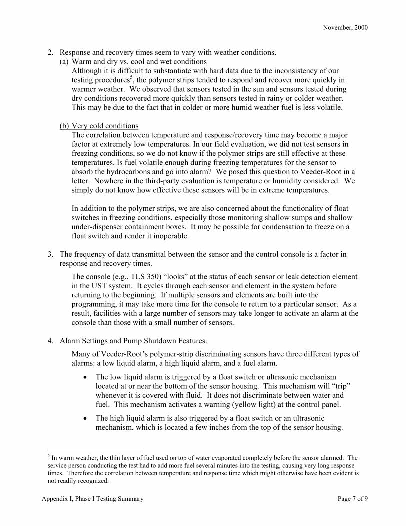
2. Response and recovery times seem to vary with weather conditions.(a) Warm and dry vs. cool and wet conditions
Although it is difficult to substantiate with hard data due to the inconsistency of ourtesting procedures5, the polymer strips tended to respond and recover more quickly inwarmer weather. We observed that sensors tested in the sun and sensors tested duringdry conditions recovered more quickly than sensors tested in rainy or colder weather.This may be due to the fact that in colder or more humid weather fuel is less volatile.
(b) Very cold conditionsThe correlation between temperature and response/recovery time may become a majorfactor at extremely low temperatures. In our field evaluation, we did not test sensors infreezing conditions, so we do not know if the polymer strips are still effective at thesetemperatures. Is fuel volatile enough during freezing temperatures for the sensor toabsorb the hydrocarbons and go into alarm? We posed this question to Veeder-Root in aletter. Nowhere in the third-party evaluation is temperature or humidity considered. Wesimply do not know how effective these sensors will be in extreme temperatures.
In addition to the polymer strips, we are also concerned about the functionality of floatswitches in freezing conditions, especially those monitoring shallow sumps and shallowunder-dispenser containment boxes. It may be possible for condensation to freeze on afloat switch and render it inoperable.
3. The frequency of data transmittal between the sensor and the control console is a factor inresponse and recovery times.
The console (e.g., TLS 350) “looks” at the status of each sensor or leak detection elementin the UST system. It cycles through each sensor and element in the system beforereturning to the beginning. If multiple sensors and elements are built into theprogramming, it may take more time for the console to return to a particular sensor. As aresult, facilities with a large number of sensors may take longer to activate an alarm at theconsole than those with a small number of sensors.
4. Alarm Settings and Pump Shutdown Features.
Many of Veeder-Root’s polymer-strip discriminating sensors have three different types ofalarms: a low liquid alarm, a high liquid alarm, and a fuel alarm.
• The low liquid alarm is triggered by a float switch or ultrasonic mechanismlocated at or near the bottom of the sensor housing. This mechanism will “trip”whenever it is covered with fluid. It does not discriminate between water andfuel. This mechanism activates a warning (yellow light) at the control panel.
• The high liquid alarm is also triggered by a float switch or an ultrasonicmechanism, which is located a few inches from the top of the sensor housing.
5 In warm weather, the thin layer of fuel used on top of water evaporated completely before the sensor alarmed. Theservice person conducting the test had to add more fuel several minutes into the testing, causing very long responsetimes. Therefore the correlation between temperature and response time which might otherwise have been evident isnot readily recognized.

November, 2000
Appendix I, Phase I Testing Summary Page 8 of 9
Again, this mechanism cannot discriminate between water and fuel. Thismechanism activates an alarm (red light) at the control panel.
• A fuel alarm is triggered by a polymer strip that runs the length of the sensorhousing, from the bottom of the sensor to the top float switch. Unless the polymerstrip detects hydrocarbons, alarms from this mechanism are considered anindication of water intrusion. This mechanism activates an alarm (red light) at thecontrol panel.
Both warnings and alarms are designed to alert the operator that there is something wrongwith the UST system. Each requires investigation, and should receive an appropriateresponse from the operator. Warnings and alarms may also be programmed to activatepump shut-down, which turns off the turbine so that the UST cannot operate. Pump shut-down is generally only done with alarms.
If warnings or alarms are ignored and the liquid level exceeds the height of the top floatswitch, the sensor no longer detects additional fuel or water entering the sump. Thesensor becomes ineffective and no longer provides leak detection; therefore, pump shutdown at the high level alarm is a must.
5. High Vapor Mode
Another feature of the Veeder-Root control panel is the “High Vapor Mode.” Thisoperating mode is designed for use in areas where background levels of hydrocarbonvapors are high enough to activate the fuel alarm, even though the UST system is notleaking. This may be due to a previous release of product, or possibly the materials andadhesives used in the construction of the UST itself may release vapors. “High VaporMode” is a tool used to eliminate false alarms. When the console is configured in “HighVapor Mode,” the sensor will not sound a fuel alarm unless it detects both the presence ofliquid and hydrocarbons. The low liquid alarm mechanism must be triggered and theresistance in the polymer strip must be high enough to trigger a fuel alarm.
Although the sensors we tested in “High Vapor Mode” seemed to be generally effective,they have not been third-party certified for operation in “High Vapor Mode” versus “LowVapor Mode.”
6. Lack of Field Testing Procedures.
Although each manufacturer may provide its own manual of procedures for testingdiscriminating sensors, there are several different tests a technician can run. Someagencies require a test of the low and high liquid alarms only. Some agencies requiretesting the sensors in fuel and water separately. And some agencies require each sensorto be tested in fuel, in water, and in a fuel/water mixture.
Based on the results of our field testing, we determined that it is necessary to periodicallytest all sensors in fuel. Even though the consoles are designed to run diagnostics on thesensors, the consoles do not always recognize problems with sensors or their wiring. Weencountered two or three sensors that were either not programmed properly or had wiringproblems. These programming or wiring problems were only discovered through
November, 2000
Appendix I, Phase I Testing Summary Page 9 of 9
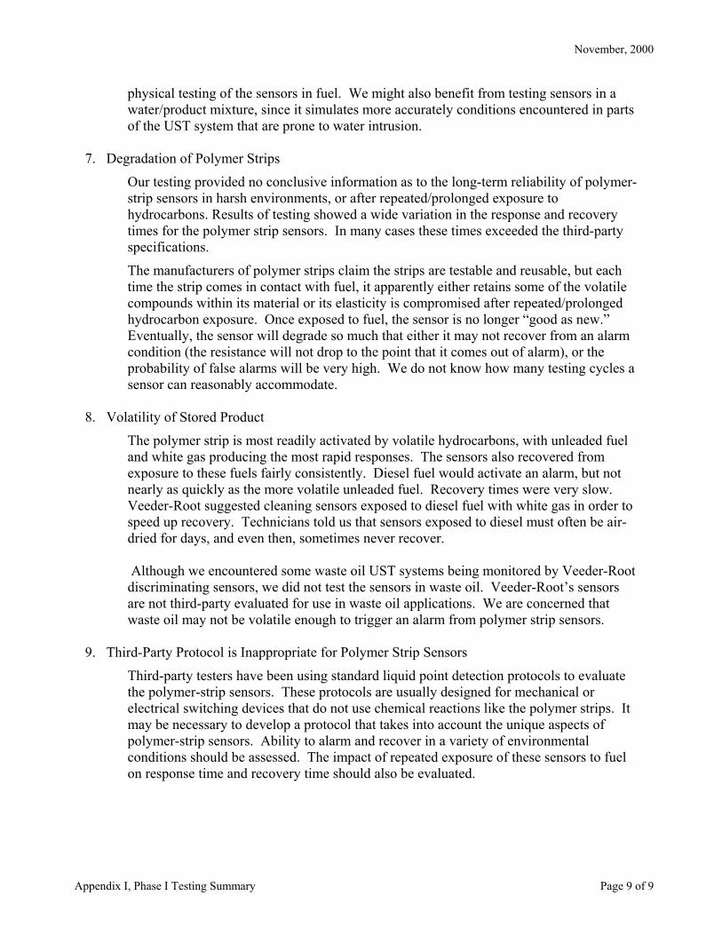
physical testing of the sensors in fuel. We might also benefit from testing sensors in awater/product mixture, since it simulates more accurately conditions encountered in partsof the UST system that are prone to water intrusion.
7. Degradation of Polymer Strips
Our testing provided no conclusive information as to the long-term reliability of polymer-strip sensors in harsh environments, or after repeated/prolonged exposure tohydrocarbons. Results of testing showed a wide variation in the response and recoverytimes for the polymer strip sensors. In many cases these times exceeded the third-partyspecifications.
The manufacturers of polymer strips claim the strips are testable and reusable, but eachtime the strip comes in contact with fuel, it apparently either retains some of the volatilecompounds within its material or its elasticity is compromised after repeated/prolongedhydrocarbon exposure. Once exposed to fuel, the sensor is no longer “good as new.”Eventually, the sensor will degrade so much that either it may not recover from an alarmcondition (the resistance will not drop to the point that it comes out of alarm), or theprobability of false alarms will be very high. We do not know how many testing cycles asensor can reasonably accommodate.
8. Volatility of Stored Product
The polymer strip is most readily activated by volatile hydrocarbons, with unleaded fueland white gas producing the most rapid responses. The sensors also recovered fromexposure to these fuels fairly consistently. Diesel fuel would activate an alarm, but notnearly as quickly as the more volatile unleaded fuel. Recovery times were very slow.Veeder-Root suggested cleaning sensors exposed to diesel fuel with white gas in order tospeed up recovery. Technicians told us that sensors exposed to diesel must often be air-dried for days, and even then, sometimes never recover.
Although we encountered some waste oil UST systems being monitored by Veeder-Rootdiscriminating sensors, we did not test the sensors in waste oil. Veeder-Root’s sensorsare not third-party evaluated for use in waste oil applications. We are concerned thatwaste oil may not be volatile enough to trigger an alarm from polymer strip sensors.
9. Third-Party Protocol is Inappropriate for Polymer Strip Sensors
Third-party testers have been using standard liquid point detection protocols to evaluatethe polymer-strip sensors. These protocols are usually designed for mechanical orelectrical switching devices that do not use chemical reactions like the polymer strips. Itmay be necessary to develop a protocol that takes into account the unique aspects ofpolymer-strip sensors. Ability to alarm and recover in a variety of environmentalconditions should be assessed. The impact of repeated exposure of these sensors to fuelon response time and recovery time should also be evaluated.

APPENDIX IIWorkplan for Phase II of the Field Evaluation

Appendix II, Workplan Page 1 of 1
SWRCB Sensor Field Evaluation Workplan (Phase II) – July 3, 2001
Team MembersProject Supervisor: Shahla Farahnak, P.E.Project Coordinator: Scott BaconAssistant Coordinator: Raed MahdiField Testing Staff: Raul Barba, Eric Luong, and Jennifer Redmond
Purpose of the ProjectThis project is intended to evaluate the functionality of liquid and vapor sensors used to monitor USTsystems. The focus will be on “real world” effectiveness, with testing performed at operating facilitieswhere the sensors are currently installed. The study is designed to:
• Evaluate the functionality of sensors used in California;• Check the adequacy of field-testing procedures for sensors (or work with manufacturers to
develop field-testing procedures if they are not already available);• Determine if sensors in the field perform consistently with the specifications outlined in their
third-party evaluations; and• Determine if the third-party evaluation protocol currently used is suitable for each of the sensor
types evaluated with that protocol.
Coordinating Field EffortsIn order for us to test at a UST facility, several people must be present or notified. At a minimum, thiswill include SWRCB staff and a service technician on site, as well as notification of the facilityowner/operator. Additionally, local agency inspectors and sensor manufacturers may be present. Weplan to work with local agencies and maintenance contractors to coincide our testing with the requiredannual maintenance inspections already scheduled at the facilities
Data Collection Process• Field Testing Method – Experienced service technicians will conduct the testing. They will
access sensors in sumps, tank interstice, dispenser pans, excavation linings, and monitoring wells.The sensors will be immersed in water at a depth corresponding to their third-party evaluation. Inaddition, discriminating sensors will be tested in fuel and/or a fuel/water mixture.
• Data Recording – Our staff will observe the testing and record data. We will record sensorresponse and recovery time, as well as information about the sensor make, model, andapplication. Additionally, we will record data about the facility and the condition of the area thesensor is located in. Through careful collection and analysis of data, we hope to determine whatfactors may adversely effect sensor performance.
• Industry Professional’s Survey - In addition to the data collected from field-testing, we willsurvey experienced maintenance technicians and inspectors. Their responses will be used tosupplement our field data and give us a clearer picture of sensor effectiveness.
Safety ConsiderationsQualified contractors will perform all hands-on testing. They have been trained to safely deal with theequipment and hazardous substances found at the facilities where our testing will take place. Our staffwill only observe and record data, but all applicable standards of safety will be adhered to. This includes,but is not limited to, proper securing of the work area from traffic hazards.
Final Report/SummaryA thorough report will be completed at the end of field-testing. It will detail our testing activities andpresent the data collected from both the tests and completed surveys. In addition, the report will stateconclusions and recommendations based on the results of our study.

APPENDIX IIILocation of Facilities Included in the Field Evaluation

Appendix III, Location of facilities included in the field evaluation Page 1 of 1
Location of Facilities Included in the Field Evaluation of Underground Storage Tank
System Leak Detection Sensors

APPENDIX IVField Data Collection Forms

Appendix IV, Field Data Collection Forms Page 1 of 3
SWRCB SENSOR FIELD EVALUATIONSITE DATA COLLECTION FORM
Site # ________________________
SITE INFORMATIONDate: Time Testing Begins: Time Testing Ends:Facility Name: Address:
Major Oil Independent Oil Government Agency Facility Ownership:Other:
Tank Type: Single-Wall Double-Wall Steel Fiberglass Dry Hydrostatic
Piping Type: Single-Wall Double-Wall Pressurized Suction Steel Fiberglass Flex Fiber Trench
# of Tanks: # of Sumps: # of Dispensers:
STAFFSWRCB Staff Present:Local Agency StaffPresent
Agency:
Service Technician(s) Conducting Test:Contractor: Years in Industry:Manufacturer’sRepresentatives:
Manufacturer:
WEATHER CONDITIONSTemperature at Start of Testing: Temperature at End of Testing:Humidity at Start of Testing: Humidity at End of Testing:
Sunny Cloudy Windy Light Rain GeneralConditions: Heavy Rain Fog Other:
COMMENTS:

Appendix IV, Field Data Collection Forms Page 2 of 3
SWRCB SENSOR FIELD EVALUATION, SENSOR DATA COLLECTION FORMEQUIPMEMNT INFORMATION
Sensor Make: Sensor Model:Sensor Serial #: Sensor Manufacture Date:
Control Panel Make: Control Panel Model:Control Panel Serial #: Control Panel
Manufacture Date:Float Switch Ultrasonic Product Permeable Optical Operating Principle:Capacitance Change Product Soluble Thermal Conductivity Conductivity
Discriminating? Y N Continuous? Y N Reusable? Y N Listed in LG-113? Y N
APPLICATION INFORMATIONTank Interstice Pump Sump Fill Sump UDC Sensor Location:Vapor Well Groundwater Well Trench Liner
Is Sensor at Lowest Point? Yes No NA
Is Wiring Connected Properly?Yes No NA
Total # of SensorsRecorded on this Form:
Is Clean and Dry Contains Water Contains Debris Brine-Filled Sensor Location… (check all that apply) Contains Product Contains Backfill Has Strong Vapor Smell
Regular Unleaded Mid-Grade Unleaded Premium Unleaded Water Sensor is Monitoring forthe Presence of… Diesel Brine Waste Oil Other:
Steel PVC/Plastic Fiberglass Tank/Sump/UDCMonitored by Sensor is… Membrane/Liner HDPE Other:Tank/Sump/UDC Manufacturer:
WATER TEST (Low)Water Height: Response TimeRecovery Time Pump Shut-Down Yes No NAAlarm Activated: Water Product Both None Test Result: Pass Fail
WATER TEST (High)Water Height: Response TimeRecovery Time Pump Shut-Down Yes No NAAlarm Activated: Water Product Both None Test Result: Pass Fail
PRODUCT TEST Product Used:Product Height: Response TimeRecovery Time: Pump Shut-Down Yes No NAAlarm Activated: Water Product Both None Test Result: Pass Fail
PRODUCT ON WATER TESTWater Height: Product Thickness:Response Time: Recovery Time:Alarm Activated: Water Product Both None Pump Shut-Down Yes No NAProduct Used: Test Result: Pass Fail
After testing this sensor was: Repaired1 Replaced Re-Tested2 Re-Installed COMMENTS:
1 Describe repairs in Comments section2 If the sensor is re-tested, record test data in another sensor form and attach it to the back of this form

1) Sensor Location: T1 to T4 are sensors in tanks 1-4, S1 to S4 are sensors in the turbine sumps of tanks 1-4, additional sensor locations should be included in the “comments” section of this form.2) Alarm Type: W = Water, F = Fuel, N = None. Include both W and F if applicable.3) Times: All times will be taken from the moment the sensor is placed in the fluid. The clock will not be zeroed between alarm activation and recovery.4) Indicate any sensors that were replaced, noting the model # of the old and new sensors as well as the reason for replacement.
Appendix IV, Field Data Collection Forms Page 3 of 3
Veeder-Root Discriminating Sensor Field Performance Test
Site Address: Date:
Testing Contractor: SWRCB Staff:
Weather Conditions: Diameter of test apparatus (in.): Site ID #:
High Water Level Fuel Water/Fuel MixtureResponse Response Response Recovery
Time(mm:ss)
SensorModel
WaterLevel(in.)
Time toAlarm
(mm:ss)
AlarmType
(WFN)
RecoveryTime
(mm:ss)
FuelLevel(in)
Time inFuel
(mm:ss)Time toAlarm
(mm:ss)
AlarmType
(WFN)
RecoveryTime
(mm:ss)
WaterLevel(in.)
FuelThickness
(in.)
Time inLiquid
(mm:ss)Time toAlarm
(mm:ss)
AlarmType
(WFN)
PassOr
Fail?
S1
S2
S3
S4
T1
T2
T3
T4
Comments:

APPENDIX VSensor Survey Distribution Letter, Survey Form, Results, and Comments

State Water Resources Control BoardDivision of Clean Water Programs
1001 I Street • Sacramento, California 95814 • (916) 341-5871Mailing Address: P.O. Box 944212 • Sacramento, California • 94244-2120
FAX (916) 341-5808 • Internet Address: http://www.swrcb.ca.gov
California Environmental Protection Agency Recycled Paper
Winston H. HickoxSecretary for
EnvironmentalProtection
Gray DavisGovernor
October 24, 2001
TO: Interested Parties
SURVEY FORM FOR SENSOR FIELD STUDY
We are sending this letter to you, as someone who may have expertise in the performance of the varioussensors used in UST systems. We are concerned about the performance of these sensors, specificallythose in tank-top sumps, tank annular spaces, and under dispenser containment. As you know, theirperformance is critical in detecting leaks. Therefore, we have initiated our own study to evaluate theireffectiveness under actual operating conditions.
We plan to visit 200 operating UST facilities and collect data on sensor performance. However, werecognize that our field study is limited and would be incomplete without input from those who havevaluable first-hand experience with these sensors. Therefore, we are requesting your assistance tocomplete the enclosed survey form and return it to us. This will allow us to incorporate your knowledgeand experience into our study. We estimate it will take approximately 30 minutes to complete the entiresurvey, however we are interested in your views even if you can only complete a portion.
Please distribute the survey to anyone in your organization who routinely works with UST leak detectionsensors. This includes, but is not limited to, service technicians, inspectors, installers, and environmentalmanagers. Please return the completed surveys by November 15, 2001 to:
Attention: Scott BaconState Water Resources Control BoardDepartment of Clean Water ProgramP.O. Box 944212Sacramento, CA 94244-2120Fax: (916) 341-5808
If you prefer, you may complete and submit the survey online at:http://www.calcupa.net/support/index.htm
If you have any questions regarding this survey, please contact Scott Bacon at (916) 341-5873 or email:[email protected].
Sincerely,
- ORIGINAL SIGNED BY -
Shahla Dargahi Farahnak, P.E., ChiefEngineering Unit 2Underground Storage Tank Program
Enclosure

Appendix V, Survey Page 1 of 3
UST SENSOR STUDY SURVEYSTATE WATER RESOURCES CONTROL BOARD
(Please answer all the questions that are applicable based on your experience in the field)
Information provided by: – (Leave blank if you prefer to submit this survey anonymously)
Name: _________________________________ Company/Agency: _____________________________Address: _______________________________________________ Telephone: ____________________
GENERAL INFORMATION1. What is your affiliation? Local Agency Inspector Technician Consultant
Owner/Operator Other (Specify) _______________________
2. How many years of experience do you have in the UST field? ___________
3. Average number of UST facilities you inspect/service monthly? _______ Not applicable
OVERALL SENSOR INFORMATION4. Do you perform/require a functional test (i.e. accessing the sensors and activating an alarm by flipping
them over, immersing them in liquid, etc.) of all sensors during the annual UST monitoring equipmentcertification? Yes No
5. What percentage of the sensors you encounter in the field are failing the functional tests?
<5% 5-10% 10-20% 20-30% 30-40% 40-50% >50%
6. What percentage of the sensor failures are due to the following factors:
a) Poor design: <5% 5-10% 10-20% 20-30% 30-40% 40-50% >50%b) Installation: <5% 5-10% 10-20% 20-30% 30-40% 40-50% >50%c) Maintenance: <5% 5-10% 10-20% 20-30% 30-40% 40-50% >50%d) Programming: <5% 5-10% 10-20% 20-30% 30-40% 40-50% >50%e) Tampering: <5% 5-10% 10-20% 20-30% 30-40% 40-50% >50%f) Other: <5% 5-10% 10-20% 20-30% 30-40% 40-50% >50%
7. Sensor failure is most common in: Steel Tanks Dry Interstice Fiberglass Tank
Wet Interstice Fiberglass Tank Tank-Top (pump/fill) Sumps Under Dispenser Containment Location is not a factor in sensor failure

Appendix V, Survey Page 2 of 3
SENSOR COMPARISON8. Please complete this section to the best of your knowledge:
Floatswitch
Polymerstrip
Optical Prism Ultrasonic Conductivity Capacitancechange
% failure rate
* Indicate mostcommon reason(s)for failure
*Failure Reasons: P = Programming M = Maintenance I = Installation T = TamperingPD = Poor Design Other = Please indicate
9. What specific make(s) and/or model(s) of sensor are most reliable? ____________________________________________________________________________________________________________________
10. What specific make(s) and/or model(s) of sensor are least reliable? _____________________________________________________________________________________________________________________
DISCRIMINATING SENSORS11. What percentage of the sensors you use/inspect/service are discriminating sensors?
- Tank Interstice: <5% 5-10% 10-20% 20-30% 30-40% 40-50% >50%- Turbine Sumps: <5% 5-10% 10-20% 20-30% 30-40% 40-50% >50%- Under Dispenser: <5% 5-10% 10-20% 20-30% 30-40% 40-50% >50%
12. Based on your experience, discriminating sensors are ________________ when compared to non-discriminating sensors?
More reliable Less reliable Equally reliable
13. For discriminating sensors using polymer strip, what is the typical time for each of the following?
a) response in unleaded fuel: <30sec 30-60sec 1-3min 3-5min 5-10min 10-20min >20min
b) recovery in unleaded fuel: <1min 1-3min 3-5min 5-10min 10-20min >20min Not reusable
c) response in diesel fuel: <30sec 30-60sec 1-3min 3-5min 5-10min 10-20min >20min
d) recovery in diesel fuel: <1min 1-5min 5-15min 15-30min 30-60min >60min Not reusable

Appendix V, Survey Page 3 of 3
14. Is there a change in response times for polymer strip sensors after repeated exposure to fuel?
Response time for polymer-strip sensors increases after repeated exposure to hydrocarbons. Response time for polymer-strip sensors decreases after repeated exposure to hydrocarbons. Response time for polymer strip sensors does not change after repeated exposure to hydrocarbons.
15. Which of the following methods do you most often use/require when testing discriminating sensors?
Test in water only Test in product only Test in both product and water Flip sensor over I do not test/require testing of discriminating sensors
PUMP SHUT-DOWN FEATURE16. What is the typical time delay between sensor activation and pump shut-down?
<5sec 5-10sec 10-30sec 30-45sec 45-60sec 1-2min >2min
17. For sensors programmed for pump shut-down, what percent of them shut down the pump?
<5% 5-10% 10-20% 20-30% 30-40% 40-50% >50
18. What are the most common reason(s) for failure of the pump shut-down?
Programming Maintenance Installation TamperingRelay box (Equipment problems) Other (Specify) __________________
ADDITIONAL INFORMATION19. What changes can be made to improve sensor reliability?______________________________________
________________________________________________________________________________________________________________________________________________________________________________________________________________________________________________________________________________________________________________________________________________
20. Do you have any other comments you would like to share with us? _____________________________
________________________________________________________________________________________________________________________________________________________________________________________________________________________________________________________________________________________________________________________________________________

Number of UST Facilities Inspected/Servicedby Respondent
00.5 1 2 3 4 5 6 7 8 10 12 15 20 25 30 35 50 60
UST Facilities per Month
Res
po
nse
s
Experience of Survey Respondents
00.5 1 2 3 4 5 6 7 9 10 11 12 13 15 17 20 21 30
Years Experience
Res
po
nse
s
ABOUT THE RESPONDENTS
SWRCB Sensor Field Evaluation, Survey Results71 local agency inspectors and service technicians responded to the survey. The following tables summarize their responses to a varietyof questions on UST leak detection sensors.
1
4
12
10
6
5
1
2
1
6
1
3
4
3
1 1 1 1
2
4
6
8
10
12
14
1
3
4
2
3
6
5 5
1
7
5
8
2
9
1
2
1 11
2
3
4
5
6
7
8
9
10
Appendix V, Survey Results Page 1 of 6
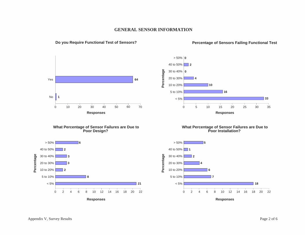
Do you Require Functional Test of Sensors? Percentage of Sensors Failing Functional Test
< 5%
5 to 10%
10 to 20%
20 to 30%
30 to 40%
40 to 50%
> 50%
1
64
Responses
33
16
10
4
0
2
0
0 5 10 15 20 25 30
What Percentage of Sensor Failures are Due toPoor Design?
21
8
2
3
3
2
6
Responses
Responses
No
Yes
0 10 20 30 40 50
0 2 4 6 8 10 12 14 16 18 20 22
< 5%
5 to 10%
10 to 20%
20 to 30%
30 to 40%
40 to 50%
> 50%
What Percentage of Sensor Failures are Due toPoor Installation?
18
7
6
4
2
1
5
Responses
0 2 4 6 8 10 12 14 16 18 20 22
< 5%
5 to 10%
10 to 20%
20 to 30%
30 to 40%
40 to 50%
> 50%
3560 70
Per
cen
tag
eP
erce
nta
ge
Per
cen
tag
e
Appendix V, Survey Results Page 2 of 6
GENERAL SENSOR INFORMATION

Location Where Sensor Failure is Most Common
Dry IntersticeFiberglass Tank
Location is not afactor in sensor failure
Steel Tanks
Tank-Top (pump/fill)Sumps
Under DispenserContainment
< 5%
5 to 10%
10 to 20%
20 to 30%
30 to 40%
40 to 50%
> 50%
What Percentage of Sensor Failures are Due toTampering?
13
4
3
2
0
1
1
Responses
0 2 4 6 8 10 12 14 16 18 20 22
15
21
1
16
2
Responses
0 2 4 6 8 10 12 14 16 18 20 22
< 5%
5 to 10%
10 to 20%
20 to 30%
30 to 40%
40 to 50%
> 50%
What Percentage of Sensor Failures are Due toPoor Maintenance?
15
8
6
5
2
4
1
Responses
0 2 4 6 8 10 12 14 16 18 20 22
< 5%
5 to 10%
10 to 20%
20 to 30%
30 to 40%
40 to 50%
> 50%
What Percentage of Sensor Failures are Due toImproper Programming?
14
13
4
6
1
3
2
Responses
0 2 4 6 8 10 12 14 16 18 20 22
Per
cen
tag
e
Per
cen
tag
e
Per
cen
tag
e
Appendix V, Survey Results Page 3 of 6

Equally Reliable
Less Reliable
More Reliable
Reliability of Discriminating Sensorsas Compared to Non-Discriminating
10
41
2
Responses
0 5 10 15 20 25 30 35 40 45
< 5%
5 to 10%
10 to 20%
20 to 30%
30 to 40%
40 to 50%
> 50%
Percentage of Discriminating Sensors in Tank Interstice
39
6
4
5
3
1
0
Responses
0 5 10 15 20 25 30 35 40
< 5%
5 to 10%
10 to 20%
20 to 30%
30 to 40%
40 to 50%
> 50%
Percentage of Discriminating Sensors in Turbine Sumps
28
8
7
7
4
1
4
Responses
0 5 10 15 20 25 30 35 40
< 5%
5 to 10%
10 to 20%
20 to 30%
30 to 40%
40 to 50%
> 50%
Percentage of Discriminating Sensors in UDC
29
10
6
4
4
1
3
Responses
0 5 10 15 20 25 30 35 40
Per
cen
tag
e
Per
cen
tag
e
Per
cen
tag
e
Appendix V, Survey Results Page 4 of 6
DISCRIMINATING SENSOR INFORMATION

Discriminating Sensor Response Time in Unleaded Fuel
4
6
9
4
7
2
3
Responses
Discriminating Sensor Recovery Time in Unleaded Fuel
1
5
2
4
10
9
3
0 2 4 6 8 10 12
< 1 min
3 to 5 mins
10 to 20 mins
not reusable
Discriminating Sensor Response Time in Diesel Fuel
2
6
4
2
3
4
10
< 30 secs
30 to 60 secs
1 to 3 mins
3 to 5 mins
5 to 10 mins
10 to 20 mins
> 20 mins
Responses
Discriminating Sensor Recovery Time in Diesel Fuel
1
3
0
0
3
11
6
Tim
eT
ime
Tim
eT
ime
1 to 3 mins
5 to 10 mins
> 20 mins
Responses
0 2 4 6 8 10 12
Responses
< 1 min
3 to 5 mins
10 to 20 mins
not reusable
1 to 3 mins
5 to 10 mins
> 20 mins
0 2 4 6 8 10 12
< 30 secs
30 to 60 secs
1 to 3 mins
3 to 5 mins
5 to 10 mins
10 to 20 mins
> 20 mins
0 2 4 6 8 10 12
Appendix V, Survey Results Page 5 of 6

Installation
Maintenance
Programming
Relay Box
Tampering
Other
How are Discriminating Sensor Being Tested?
8
21
10
9
0 5 10 15 20 25
Flip SensorOver
Test inProduct Only
Pump Shut-Down Delay Time
12
16
19
11
4
2
1
< 5 secs
5 to 10 secs
1 to 2 mins
> 2 mins
Responses
Reason for Failure of Pump Shutdown
2
8
11
28
8
3
Tim
e
Test in BothProduct and Water
Test inWater Only
Responses
0 5 10 15 20 25 30
Responses
0 5 10 15 20
Changes in Response Time for Polymer Strips AfterRepeated Exposure to Fuel
14
11
7
Responses
0 2 4 6 8 10 12 14 16
increases
decreases
does not change
10 to 30 secs
30 to 45 secs
45 to 60 secs
Appendix V, Survey Results Page 6 of 6
PUMP SHUT-DOWN INFORMATION

Appendix V, Survey Comments and Recommendations page 1 of 3
Online Survey Comments and Recommendations for the Sensor FieldEvaluation of Underground Storage Tanks:
This is a compilation of comments and recommendations we received from our survey participants. Thesecomments represent the views of the participants surveyed and may not reflect the opinions of the SWRCB.
• Discriminating sensors must be able to be tested in the actual product and must clear within a fewminutes.
• Improve maintenance of sensors and replace outdated ones.
• The polymer strip type sensor appears to be a poor design for immediate identification of a leak.Remove this type from the approval list.
• Do not allow the use of sensors associated with the MSA Tankguard. I'm not sure, but I believe thatthey are polymer strip discriminating sensors. They have an extremely low response and recovery timeof about 15-20 minutes. Also the sensitivity of the MSA Tankguard can be adjusted and always seemsto need to be adjusted at each inspection. The alarm may not sound when the sensor is being tested inliquid, but then sound when it is not being tested. I do not trust the reliability of these sensors.
• Operator training, proper maintenance and tamper proofing.
• Eliminate discriminating sensors altogether in annular spaces. Heck, eliminate them everywhere.They are only good for sumps and containment areas that are so poorly constructed that liquidintrusion is a constant problem. Repairing the sumps would be a better solution to liquid intrusionproblems.
• The positive shut down sump sensors are plastic and they stick open. Some type of new stick productis needed.
• You might want to require that all sensors be replaced regularly every 2-3 years.
• Eliminate discriminating sensors unless they have <5sec-response time. They need to be designed sothat corrosion and sticking do not occur. Needs to be such that maintenance is minimized since this isonly done annually.
• Require quarterly maintenance and inspection of sensors.
• Make them simple and easy to place. The Tri-State feature is best on systems that have no maintenancecrew.
• Overall experience with discriminating sensors is minimal, but due to survey set cases/problems, we donot allow or will approve them for use in the city. Result is problematic.
• Better design, stronger materials, and no resistors at sensor end.
• Improve design on brands listed in question 10. Discriminating sensors are not practical. I do not testthem due to recovery time. Sometimes they do not recover.
• I don't know if it is possible, but what if they made a sensor that was non-stick so that sludge would nothold the float, making it stuck. The contact points would also need to be sludge proof.
• Better installation practices. Sensors are not being hung at the correct location, i.e. at the bottom of thetank or sump.

Appendix V, Survey Comments and Recommendations page 2 of 3
• Eliminate discriminating sensors or improve technology. Operate and test sensors under varioussimulated conditions. Improve technology of annular float sensors in FG tanks to improveaccessibility/visual inspection/simulated testing.
• Be there at the annual maintenance checks. You learn a lot, see a lot of the important violations anddisrupt the business only once. The entire focus of my inspections is the leak detection systems forpiping and tanks. They must work. Operators do not like to do leak detection manually. Pushingtoward all electronic monitoring is essential for the future. Get the operators out of it. Have the ATGprint out the monthly .2 gph-passing test for tanks at least once a month automatically. Then theoperator saves this record for the inspection.
• Testers hate to test the discriminating sensors with product because they know they will have problemsgetting them cleared, if at all. If the sensors won't clear, then it must be replaced, and tested. On oneoccasion, the technician did not have a discriminating sensor replacement with him so he had to callhis shop and have someone drive one out to the site. This kept that product offline for several hours.The facility operator was not happy.
• Get rid of sacrificial sensors, and require secondary containment for all piping!!!
• My primary objective in completing this survey is to expose the problems that I have encountered intrying to test the sensors for the MSA Tankguard system. All other sensors that I have encountered aresufficiently reliable.
• The compatibility of simple contact switch sensors with the control panels is not a major issue or anoperational problem. The use of discriminating sensors is a major issue even when these sensors areused with a compatible control panel.
• We hardly see discriminating sensors. The alarm needs to go through a central alarm system in whichcase we will know of any release. Tampering defeats the purpose of monitoring. We find improperpositioning of the probe/ raised probe 80 % of the sites. Water intrusion a real problem.
• A tank system that is properly constructed and maintained should never have liquid intrusion problemsand therefore there is no need for discriminating sensors.
• Owners need a good, simple manual on the tank system components, requirements, andresponsibilities: like "straight talk on tanks" in more detail. So many stations change hands and somany employees are dueless, that comprehensive explanation of UST's is desperately needed to start toget an unformed constituency.
• Bravo box float mechanisms for dispenser containment monitoring were not mentioned in this surveybut have about a 50% failure rate due to debris or loose chains. SFSFD water tests all float monitoreddispenser pans.
• Sensor reliability or rather the lack there of, has caused local agencies to all other leak detection andtesting requirements to UST's. The confidence level in the sensors functioning properly at any giventime is low, Because of this the confidence in our UST programs goal of preventing and detectingreleases is also somewhat low. Why spend a lot of time and resources when the devices areunreliable? Also, this didn't address mechanical systems. The Bravo Float system has chronicproblems with not functioning properly after more than a year. The float does not leave very muchroom for sidewalls of channels so dirt freezes the movement. Tampering by loosening chains isextremely common. We dislike this design.
• Phasing out existing monitoring systems. I.e. pollulert, petrometer, leak-x, petrovend, etc. Notioncurrent LG-113 should be an eventually to start planning for now.

Appendix V, Survey Comments and Recommendations page 3 of 3
• Discriminating sensors add approximately 10 min. per sensor for testing and returning to operability.That adds about 2 hours to a standard gas station monitoring certification inspection.
• Question 13(d)- recovery time for diesel fuel is greater than 60 minutes.
• Please remove discriminating sensors from approved method. They are not reliable and/or do not sensefor reasonable system monitoring (if located in sump bottom with water in sump a full leak will not bedetected if the water level is above the sensor). Question 7-Sensor failure is most common in Tank Top(pump/fill) Sumps and Under Dispenser Containment.
• This survey should allow free-text answers. Some pick-list choices are inadequate. At the very least,there should be a "unknown" response.
• In the past when we arrived on site for an inspection, the maintenance contractor or operator may havealready tested and replaced any faulty sensors. This will skew the data you collect from inspectors,indicating higher performance rates.
• People raising probes due to surface water infiltration via rain or steam cleaning the parking lot, whichviolates many laws.
• Alternate technologies should be available for positive shutdown, which do not rely on the relay boxes.

APPENDIX VIField Data

Appendix VI, Definitions and List of Acronyms Page 1 of 1
Sensor Field Data Tables
List of Acronyms Acronym Meaning
MR Sensor is manually reset after an alarmMSA Mine Safety AppliancesNA Not applicable to the sensor being testedNP Not programmed for pump shut-downNT Not testedPSD Pump shut-downRec Recovery time (in seconds)Resp Response time (in seconds)UDC Under-dispenser containmentUnk Unknown. Data was unavailable
List of DefinitionsTerm Definition
Flip Test Sensor was tested by flipping it overHeights All liquid levels are reported in inchesHigh Test High-level water testingLow Test Low-level water testing. For single-level
sensors tested in water, test data will berecorded in this column
Product Sensor was tested in productSite ID #200 The 67 sensors tested during Phase I (Veeder-
Root discriminating sensors) are included inthis database under Site ID# 200
Times All response and recovery times are reportedin seconds

APPENDIX VI, TABLE 1Summary of All Failures
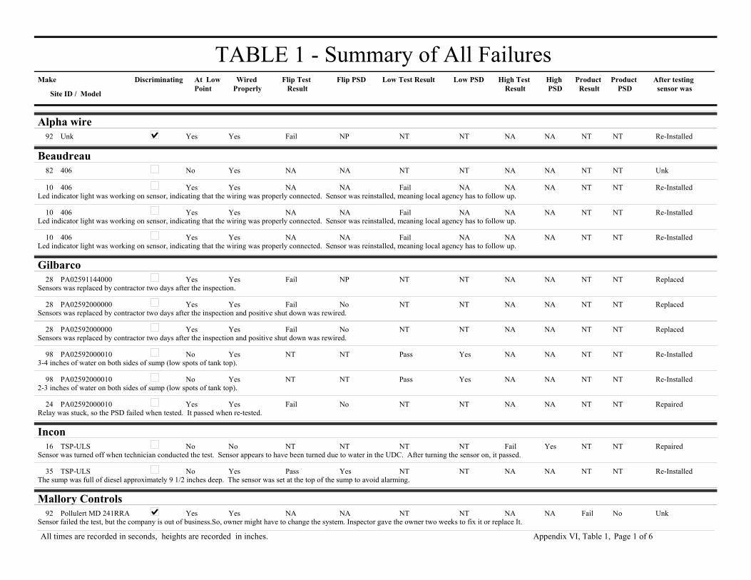
TABLE 1 - Summary of All FailuresMake At Low
PointFlip Test
ResultLow Test Result
Site ID / Model
Low PSD High Test Result
High PSD
Product Result
Product PSD
After testing sensor was
Wired Properly
Discriminating Flip PSD
Alpha wireUnk Yes Fail NT92 Yes NT NA NA NT NTNP Re-Installed
Beaudreau406 No NA NT82 Yes NT NA NA NT NTNA Unk
406 Yes NA Fail10 Yes NA NA NA NT NTNA Re-InstalledLed indicator light was working on sensor, indicating that the wiring was properly connected. Sensor was reinstalled, meaning local agency has to follow up.
406 Yes NA Fail10 Yes NA NA NA NT NTNA Re-InstalledLed indicator light was working on sensor, indicating that the wiring was properly connected. Sensor was reinstalled, meaning local agency has to follow up.
406 Yes NA Fail10 Yes NA NA NA NT NTNA Re-InstalledLed indicator light was working on sensor, indicating that the wiring was properly connected. Sensor was reinstalled, meaning local agency has to follow up.
GilbarcoPA02591144000 Yes Fail NT28 Yes NT NA NA NT NTNP Replaced
Sensors was replaced by contractor two days after the inspection.
PA02592000000 Yes Fail NT28 Yes NT NA NA NT NTNo ReplacedSensors was replaced by contractor two days after the inspection and positive shut down was rewired.
PA02592000000 Yes Fail NT28 Yes NT NA NA NT NTNo ReplacedSensors was replaced by contractor two days after the inspection and positive shut down was rewired.
PA02592000010 No NT Pass98 Yes Yes NA NA NT NTNT Re-Installed3-4 inches of water on both sides of sump (low spots of tank top).
PA02592000010 No NT Pass98 Yes Yes NA NA NT NTNT Re-Installed2-3 inches of water on both sides of sump (low spots of tank top).
PA02592000010 Yes Fail NT24 Yes NT NA NA NT NTNo RepairedRelay was stuck, so the PSD failed when tested. It passed when re-tested.
InconTSP-ULS No NT NT16 No NT Fail Yes NT NTNT Repaired
Sensor was turned off when technician conducted the test. Sensor appears to have been turned due to water in the UDC. After turning the sensor on, it passed.
TSP-ULS No Pass NT35 Yes NT NA NA NT NTYes Re-InstalledThe sump was full of diesel approximately 9 1/2 inches deep. The sensor was set at the top of the sump to avoid alarming.
Mallory ControlsPollulert MD 241RRA Yes NA NT92 Yes NT NA NA Fail NoNA Unk
Sensor failed the test, but the company is out of business.So, owner might have to change the system. Inspector gave the owner two weeks to fix it or replace It.
Page 1 of 6All times are recorded in seconds, heights are recorded in inches. Appendix VI, Table 1,

Make At Low Point
Flip Test Result
Low Test Result
Site ID / Model
Low PSD High Test Result
High PSD
Product Result
Product PSD
After testing sensor was
Wired Properly
Discriminating Flip PSD
MSATankgard 482607 No NA NT17 No NT NA NA Fail YesNA Repaired
Sensor initially turned off. Appears to have been turned off due to product in the sump. Sensor worked when turned on; sensor not at lowest point - about 8" above.
Tankgard 482607 Yes NA NT17 Yes NT NA NA Fail NoNA UnkHad to leave site before witnessing removal or re-installation of sensor.
Red JacketLiquid Refraction Sensor No Pass NT20 Yes NT NA NA NT NTYes Re-Installed
Sensor has been pulled up due to high water in the fill/vapor sump.
RonanLS-3 No Fail NT20 Yes NT NA NA NT NTNo Unk
Sensor appears to be good during a continuity test, but appears not to be hooked up to the control panel.
LS-3 Yes Fail NT47 No NT NA NA NT NTYes RepairedSensor would not come out of alarm after testing. Pump would not come on. Contractor repaired the facility. Problem was wiring inside the building, near the control panel.
LS-3 Yes Fail NT20 No NT NA NA NT NTNo UnkSensor appeared to be functional when technician tested for continuity, but did not activate an alarm at the panel. Tech suspects problem with wiring between sensor and panel.
LS-3 Yes Fail NT32 Yes NT NA NA NT NTNP RepairedFloat was stuck. Technician had to shake it to loosen it, then sensor went into alarm.
LS-7 No Pass NT1 Yes NT NA NA NT NTNP Re-InstalledThe sensor could not be taken out of the tank interstice; therefore the sensor was activated within the tank.
UniversalLALS-1 Yes Fail NT94 Yes NT NA NA NT NTNA Unk
Contractor waited for 2 minutes for the sensor to response, but never did. Sensor had to be replaced.
LALS-1 Yes NA Fail95 Yes No NA NA NT NTNA UnkSensor was not tested because it was stuck in the interstitial space.
LAVS-1 Yes NA Fail94 Yes No NA NA NT NTNA Unk
Veeder-Root794380-208 No Fail NT85 Yes NT NA NA NT NTNo Replaced
The contractor decided to stop testing the sensor after it failed to respond for more than 2 minutes and replace it with a new sensor.
794380-208 No Fail NT10 Yes NT NA NA NT NTNo Re-InstalledAlarm activated at the control panel, but no pump shutdown. ( printer said pump shutdown occurred, but pump continued to run. Picture of sensor is site 7 #2.). Follow up was done on this site and Inspector confirmed that the PSD is functioning properly.
794380-208 No NT Pass91 Yes Yes NA NA NT NTNT Re-InstalledFill bucket was detached. Stick was in the product line (to prevent the flapper from shutting down the flow)
Page 2 of 6All times are recorded in seconds, heights are recorded in inches. Appendix VI, Table 1,

Make At Low Point
Flip Test Result
Low Test Result
Site ID / Model
Low PSD High Test Result
High PSD
Product Result
Product PSD
After testing sensor was
Wired Properly
Discriminating Flip PSD
794380-208 No NT Pass91 Yes Yes NA NA NT NTNT Re-InstalledFill bucket was detached. Stick was in the product line (to prevent the flapper from shutting down the flow)
794380-208 No NT Pass91 Yes Yes NA NA NT NTNT Re-InstalledFill bucket was detached. Stick was in the product line (to prevent the flapper from shutting down the flow)
794380-208 No NT Pass91 Yes Yes NA NA NT NTNT Re-TestedSensor timed out & Technician had to go and re-set it to shut down the pump.
794380-208 No NT Pass91 Yes Yes NA NA NT NTNT Re-InstalledFill bucket was detached. Stick was in the product line (to prevent the flapper from shutting down the flow). Most of sensors timed out & Technician had to go and re-set it to shut down the pump.
794380-208 No NT Pass91 Yes Yes NA NA NT NTNT Re-TestedSensor timed out & Technician had to go and re-set it to shut down the pump.
794380-208 No NT Pass91 Yes Yes NA NA NT NTNT Re-TestedSensor timed out & Technician had to go and re-set it to shut down the pump.
794380-208 No NT Pass91 Yes Yes NA NA NT NTNT Re-TestedSensor timed out & Technician had to go and re-set it to shut down the pump.
794380-208 No Pass NT42 Yes NT NA NA NT NTNP Re-InstalledContains a substantial amount of water.
794380-208 No Pass NT76 Yes NT NA NA NT NTNP Re-Installed
794380-208 No Pass NT73 Yes NT NA NA NT NTYes Re-InstalledSensor was raised about 4 inches from the bottom of the sump.
794380-208 No Pass NT33 Yes NT NA NA NT NTNP Re-Installed
794380-208 No Pass NT33 Yes NT NA NA NT NTNP Re-Installed
794380-208 No Pass NT33 Yes NT NA NA NT NTNP Re-Installed
794380-208 No Pass NT33 Yes NT NA NA NT NTNP Re-Installed
794380-208 No Pass NT33 Yes NT NA NA NT NTNP Re-Installed
794380-208 No Pass NT33 Yes NT NA NA NT NTNP Re-Installed
794380-208 No Pass NT79 Yes NT NA NA NT NTYes Re-InstalledProduct is leaking out of the top of the turbine pump.
794380-208 No Pass NT79 Yes NT NA NA NT NTYes Re-InstalledProduct is leaking out of the top of the turbine pump.
794380-208 No Pass NT79 Yes NT NA NA NT NTYes Re-InstalledProduct is leaking out of the top of the turbine pump.
794380-208 No Pass NT42 Yes NT NA NA NT NTYes Re-InstalledThe sensor was not located at the lowest point in the tank. Technician lowered it and activetd an alarm.
Page 3 of 6All times are recorded in seconds, heights are recorded in inches. Appendix VI, Table 1,

Make At Low Point
Flip Test Result
Low Test Result
Site ID / Model
Low PSD High Test Result
High PSD
Product Result
Product PSD
After testing sensor was
Wired Properly
Discriminating Flip PSD
794380-208 No Pass NT76 Yes NT NA NA NT NTNP Re-Installed
794380-208 No Pass NT62 Yes NT NA NA NT NTNP Re-Installed2-3 gallons of product in the sump. Sensor was raised above the product level. Sensor in pump sump was not programmed to shut down pump.
794380-208 No Pass NT62 Yes NT NA NA NT NTNP Re-Installed2-3 gallons of product in the sump. Sensor was raised above the product level. Sensor in pump sump was not programmed to shut down pump.
794380-208 No Pass NT42 Yes NT NA NA NT NTYes Re-Installed
794380-208 No Pass NT85 Yes NT NA NA NT NTYes Re-InstalledThere was a hole in the sump, approximately 1 1/2" diam. Electrical wiring below penetration lines. Hydrostatic test was performed to the highest penetration lines at 16 minutes per cycle.Test at 16 psi and fail if below 12 psi. Fill sump is not clean..
794380-208 No Pass NT10 Yes NT NA NA NT NTYes Re-Installed2 sensors, 1 raised in sump and the other was a the lowest point. Both responded and activated pump shut off. Picture of sensor was taken.
794380-208 Yes Fail NT88 Yes NT NA NA NT NTNo ReplacedTechnician waited for over 2 minutes, but sensor did not alarm. Finally inspector decided to call the test off and replace the sensor. Testing was done on the new sensor and it passed.
794380-341 Unk NA Unk200 Unk Unk NA NA Fail UnkNA Unk
794380-341 Unk NA Unk200 Unk Unk NA NA Fail UnkNA Unk
794380-341 Yes NA NT19 Yes NT NA NA Fail NoNA ReplacedReplaced with same type of sensor.
794380-341 Yes NA NT38 Yes NT NA NA Fail NANA ReplacedSensor was tested with both unleaded gasoline and waste oil. Both cases, water alarms were observed. Sensor was not approved for use in waste oil. After testing, sensor was replaced and it passed the product test.
794380-341 Yes NA Pass38 Yes NA NA NA Fail NoNA ReplacedSensor sets water alarm for product test. After testing the sensor was replaced and the new sensor was setting the right alarm.
794380-341 Yes NA Pass38 Yes NA NA NA Fail NoNA ReplacedSensor sets water alarm for product test. After testing, sensor was replaced and the new sensor was setting the right alarm.
794380-341 Yes NA Pass64 Yes Yes NA NA Fail YesNA UnkDetected product as water. Since pump shuts down for product or water, Local Agency did not require sensor to be changed. Owner will replace sensor or re-program as non-discriminating.
794380-341 Yes NA Pass77 Yes Yes NA NA Fail YesNA RepairedTechnician had to clean the sensor with a rag completely (especially in the small window at sensor's center) before fuel could be detected. After cleaning sensor did detect fuel.
794380-341 Yes NA Pass64 Yes Yes NA NA Fail YesNA UnkDetected product as water. Since pump shuts down for product or water, Local Agency did not require sensor to be changed. Owner will replace sensor or reprogram as non-discriminating.
794380-341 Yes NA Pass77 Yes Yes NA NA Fail YesNA RepairedTechnician had to clean the sensor with a rag completely (especially in the small window at sensor's center) before fuel could be detected. After cleaning sensor did detect fuel.
794380-341 Yes NA Pass77 Yes Yes NA NA Fail YesNA RepairedTechnician had to clean the sensor with a rag completely (especially in the small window at sensor's center) before fuel could be detected. After cleaning sensor did detect fuel.
794380-350 Yes NA Pass84 Yes NA Pass Yes Fail YesNA ReplacedSensor did not come out of alarm after being tested in product, so technician replaced it.
Page 4 of 6All times are recorded in seconds, heights are recorded in inches. Appendix VI, Table 1,

Make At Low Point
Flip Test Result
Low Test Result
Site ID / Model
Low PSD High Test Result
High PSD
Product Result
Product PSD
After testing sensor was
Wired Properly
Discriminating Flip PSD
794380-350 Yes NA Pass84 Unk NA Fail No Fail NoNA Re-InstalledTechnician suspected a problem with the wiring at this site.
794380-350 Yes NA Pass84 Unk NA Fail No Fail NoNA Re-InstalledSensor alarmed, but failed PSD. Problem with the relay is suspected.
794380-350 Yes NA Pass84 No NA Fail No Fail NoNA ReplacedSensor did not respond during high water or product testing. Technician suspected wiring problem, since sensor was replaced but test results did not change.
794380-352 No NT Fail22 Yes No Pass Yes NT NTNT Re-InstalledSensor's low float did not activate (would not reset). Sensor was replaced by the owner without informing the local agnecy nor the contractor who does the routine inspection. Apparently, they did not retest sensor's functinality.
794380-352 Unk NT Unk200 Unk Unk Pass Unk Fail UnkNT Unk
794380-352 Unk NT Unk200 Unk Unk Pass Unk Fail UnkNT
794380-352 Yes NT NT82 No NT NT NT NT NTNT UnkWiring malfunctioning.
794380-352 Yes NT NT82 No NT NT NT NT NTNT UnkWiring malfunctioning.
794390-205 No NT NT65 Yes NT NA NA Pass NANT Re-InstalledSump had oil in it. Sensor was raised above the oil, but alarmed when technician lowered it into the oil. Contractor was notified to pump out the oil that day.
794390-205 No Pass NT46 Yes NT NA NA NT NTYes Re-InstalledSensor was raised approximately 1 foot from bottom of the sump.
794390-407 No NT NT29 No NT NA NA NT NTNT RepairedThe sensor was located at the top of the tank, at the access port. The pull-string was broken. Inspector said sensor must be fixed immediately. The sensor was not functionally tested during this inspection. Afollow up was done & sensor was repaired.
794390-407 Yes Fail NT73 Yes NT NA NA NT NTNP RepairedSensor would not go into alarm until the techician shook it vigorously. Float was stuck. Interstice was moist, but not enough liquid to activate an alarm.
794390-407 Yes Fail NT73 Yes NT NA NA NT NTNP RepairedSensor would not go into alarm until the techician shook it vigorously. Float was stuck.
794390-409 Unk Fail NT81 Unk NT NA NA NT NTNP Re-InstalledSensor was wedged between the primary and secondary tank walls and cannot be removed to verify sensor type. Alarm was not set at the control panel by pulling it like the prevous two tanks.
794390-409 Unk Fail NT81 Yes NT NA NA NT NTNP Re-InstalledSensor was wedged between the primary and secondary tank walls and cannot be removed to verify sensor type. Alarm was set at the control panel by pulling it. The response time was estimated because there was no way of knowing when sensor was triggered.
794390-420 NA Fail NT51 Yes NT NA NA NT NTNP UnkThe sensor was missing the float. Follow up was made with local agency and confirmed that the technician repaired the sensor. However, inspector did not peform re-inspection.
794390-420 No Pass NT55 Yes NT NA NA NT NTNP UnkThis sensor is for steel tanks, and could not be wrapped around the FG tank. Local agency instructed owner to replace.
Page 5 of 6All times are recorded in seconds, heights are recorded in inches. Appendix VI, Table 1,

Make At Low Point
Flip Test Result
Low Test Result
Site ID / Model
Low PSD High Test Result
High PSD
Product Result
Product PSD
After testing sensor was
Wired Properly
Discriminating Flip PSD
794390-420 No Pass NT89 Yes NT NA NA NT NTYes Re-InstalledInterstitial space is full of water. Technician could not put back the sensor without calling the maintenance to remove water. Sensor was not at lowest point and wire was wrapped up.
794390-420 No Pass NT99 No NT NA NA NT NTNPWaste oil contained oil/water around the tank sump. The sensor was not located in the lowest point.
794390-420 No Pass NT89 Yes NT NA NA NT NTYes Re-Installed
794390-420 Yes Fail NT23 Yes NT NA NA NT NTNP ReplacedOriginal sensor was stuck in the interstice because of rust on casing; sensor was replaced. New sensor passed test.
Warrick ControlsDLP-1-NC Yes Fail NT7 Yes NT NA NA NT NTNP Re-Tested
Sensor was sitting in water and not alarmed. Contractor shook sensor and float moved activating the alarm. Sensor passed retest after 1-2 second alarm response.
Page 6 of 6All times are recorded in seconds, heights are recorded in inches. Appendix VI, Table 1,

APPENDIX VI, TABLE 2Field Data for Non-discriminating Sensors

TABLE 2 - Field Data for Non-Discriminating SensorSensor
LocationPanel Make
Panel Model
At Low Point
Wiring OK
Condition of Location Resp Rec Alarm PSD Result Resp Rec PSD ResultAlarm
Liquid Testing Flip Testing
Sensor Make: BeaudreauSensor Model: 404 Operating Principle: Float Switch
UDC Veeder-Root TLS-300 Yes Yes Clean/Dry 3 1 Product NA Pass NT NT NT NTNT
Sensor Model: 406 Operating Principle: Optical
UDC Beaudreau 404-4 Cut-off Yes Yes Clean/Dry 1 2 Both NA Pass NA NA NA NANASensor shuts off power to dispenser.
UDC Beaudreau 404-4 Cut-off Yes Yes Clean/Dry 1 2 Both NA Pass NA NA NA NANASensor shuts off power to dispenser.
UDC Beaudreau 404-4 Cut-off Yes Yes Clean/Dry 2 2 Both NA Pass NA NA NA NANASensor shuts off power to dispenser.
UDC Beaudreau 404-4 Cut-off Yes Yes Clean/Dry 2 2 Both NA Pass NA NA NA NANASensor shuts off power to dispenser.
UDC Beaudreau 404-4 Cut-off Yes Yes Clean/Dry 2 2 Both NA Pass NA NA NA NANASensor shuts off power to dispenser.
UDC Beaudreau 404-4 Cut-off No Yes Debris NT NT NT NT NT NA NA NA NANA
UDC Beaudreau 404-4 Cut-off Yes Yes Clean/Dry None NA None NA Fail NA NA NA NANALed indicator light was working on sensor, indicating that the wiring was properly connected. Sensor was reinstalled, meaning local agency has to follow up.
UDC Beaudreau 404-4 Cut-off Yes Yes Clean/Dry None NA None NA Fail NA NA NA NANALed indicator light was working on sensor, indicating that the wiring was properly connected. Sensor was reinstalled, meaning local agency has to follow up.
UDC Beaudreau 404-4 Cut-off Yes Yes Clean/Dry None NA None NA Fail NA NA NA NANALed indicator light was working on sensor, indicating that the wiring was properly connected. Sensor was reinstalled, meaning local agency has to follow up.
UDC Beaudreau 404-4 Cut-off Yes Yes Clean/Dry 1 2 Both NA Pass NA NA NA NANASensor shuts off power to dispenser.
UDC Beaudreau 404-4 Cut-off Yes Yes Clean/Dry 1 1 Both NA Pass NA NA NA NANAThe sensor was tested in a cup for total darkness and shut off the valve at the dispenser.
UDC Beaudreau 404-4 Cut-off Yes Yes Clean/Dry 2 5 Both NA Pass NA NA NA NANA
UDC Beaudreau 404-4 Cut-off Yes Yes Debris NT NT NT NT NT NA NA NA NANADebris and dust accumulated over the years.
Page 1 of 31All times are recorded in seconds and heights in inches. Appendix VI, Table 2,

Sensor Location
Panel Make
Panel Model
At Low Point
Wiring OK
Condition of Location Resp Rec Alarm PSD Result Resp Rec PSD ResultAlarm
Liquid Testing Flip Testing
UDC Beaudreau 404-4 Cut-off Yes Yes Clean/Dry 15 1 Both NA Pass NA NA NA NANA
UDC Beaudreau 404-4 Cut-off Yes Yes Clean/Dry 1 1 Both Yes Pass NA NA NA NANASensor failed testing 6 weeks earlier. Technician replaced control module (located under dispenser) and now sensor worked.
UDC Beaudreau 404-4 Cut-off Yes Yes Clean/Dry 1 1 Both Yes Pass NA NA NA NANASensor failed testing 6 weeks earlier. Technician replaced control module (located under dispenser) and now sensor worked.
UDC Beaudreau 404-4 Cut-off Yes Yes Clean/Dry 1 1 Both Yes Pass NA NA NA NANASensor failed testing 6 weeks earlier. Technician replaced control module (located under dispenser) and now sensor worked.
UDC Beaudreau 404-4 Cut-off Yes Yes Clean/Dry 1 1 Both Yes Pass NA NA NA NANASensor failed testing 6 weeks earlier. Technician replaced control module (located under dispenser) and now sensor worked.
UDC Beaudreau 404-4 Cut-off Yes Yes Clean/Dry 1 1 Both NA Pass NA NA NA NANA
UDC Beaudreau 404-4 Cut-off Yes Yes Clean/Dry 1 1 Both NA Pass NA NA NA NANA
UDC Beaudreau 404-4 Cut-off Yes Yes Clean/Dry 1 1 Both NA Pass NA NA NA NANA
UDC Beaudreau 404-4 Cut-off Yes Yes Clean/Dry 1 1 Both NA Pass NA NA NA NANA
UDC Beaudreau 404-4 Cut-off Yes Yes Clean/Dry 1 1 Both NA Pass NA NA NA NANA
UDC Beaudreau 404-4 Cut-off Yes Yes Clean/Dry 1 1 Both NA Pass NA NA NA NANA
Sensor Make: EmcoSensor Model: Q0003-006 Operating Principle: Optical
Tank Interstice Emco EECO 3000 Yes Yes Clean/Dry 60 60 Product NA Pass NA NA NA NANA
Tank Interstice Emco EECO 3000 Yes Yes Clean/Dry 60 60 Product NA Pass NA NA NA NANA
Tank Interstice Emco EECO 3000 Yes Yes Clean/Dry 60 60 Product NA Pass NA NA NA NANA
Tank Interstice Emco EECO 3000 Yes Yes Clean/Dry 60 60 Product NA Pass NA NA NA NANA
Sensor Model: Q0003-010 Operating Principle: Optical
Pump Sump Emco Wheaton Leak Sensor II Yes Yes Clean/Dry NT NT NT NT NT NA NA NP NANA~8 oz water in cup; panel did not support ATG, only good for open/close sensor response; pressure operating principle?
Tank Interstice Emco Wheaton Leak Sensor II Yes Yes Clean/Dry NT NT NT NT NT NA NA NA NANA~8 oz water in cup; panel did not support ATG, only good for open/close sensor response; pressure operating principle?
Sensor Make: GilbarcoSensor Model: PA02591144000 Operating Principle: Float Switch
Page 2 of 31All times are recorded in seconds and heights in inches. Appendix VI, Table 2,

Sensor Location
Panel Make
Panel Model
At Low Point
Wiring OK
Condition of Location Resp Rec Alarm PSD Result Resp Rec PSD ResultAlarm
Liquid Testing Flip Testing
Pump Sump Gilbarco EMC Yes Yes Clean/Dry NT NT NT NT NT 5 5 Yes PassProductSensor is Gilbarco equivalent of VR model -208.
Pump Sump Gilbarco EMC Yes Yes Clean/Dry NT NT NT NT NT 5 5 Yes PassProductSensor is Gilbarco equivalent of VR model -208.
Pump Sump Gilbarco EMC Yes Yes Clean/Dry NT NT NT NT NT 5 5 Yes PassProductSensor is Gilbarco equivalent of VR model -208.
Tank Interstice Gilbarco EMC Yes Yes Clean/Dry NT NT NT NT NT 360 1 NP PassBothUnable to remove and observe waste oil UST overfill sesor. Technician was able to to activate sensor within the tank.
Tank Interstice Gilbarco EMC Yes Yes Clean/Dry NT NT NT NT NT 720 1 NP PassBoth
Tank Interstice Gilbarco EMC Yes Yes Clean/Dry NT NT NT NT NT 1 1 NP PassProduct
Tank Interstice Gilbarco EMC Yes Yes Clean/Dry NT NT NT NT NT 720 1 NP PassBothMid-grade and Premium share the same annular space; some condensation; sensor casing split.
Tank Interstice Gilbarco EMC Yes Yes Clean/Dry NT NT NT NT NT 1 1 NP PassBoth
Tank Interstice Gilbarco EMC Yes Yes Clean/Dry NT NT NT NT NT 1 1 NP PassBoth
Tank Interstice Gilbarco EMC Yes Yes Clean/Dry NT NT NT NT NT 1 1 NP PassBoth
Tank Interstice Gilbarco EMC Yes Yes Clean/Dry NT NT NT NT NT 1 1 NP PassBoth
Tank Interstice Gilbarco EMC Yes Yes Clean/Dry NT NT NT NT NT 1 1 NP PassBoth
Tank Interstice Gilbarco EMC Yes Yes Clean/Dry NT NT NT NT NT 1 1 NP PassProduct
Tank Interstice Gilbarco EMC Yes Yes Clean/Dry NT NT NT NT NT None NA NP FailNoneSensors was replaced by contractor two days after the inspection.
Tank Interstice Gilbarco EMC Yes Yes Clean/Dry NT NT NT NT NT 1 1 NP PassProduct
Tank Interstice Gilbarco EMC Yes Yes Clean/Dry NT NT NT NT NT 5 5 NP PassProductThis was a two-compartment tank (midgrade and premium). The casing of the sensor was split and took the form of a bell.
Tank Interstice Gilbarco EMC Yes Yes Clean/Dry NT NT NT NT NT 5 5 NP PassProduct
Tank Interstice Gilbarco EMC Yes Yes Clean/Dry 8 5 Product NA Pass NT NT NT NTNT
Tank Interstice Gilbarco EMC Yes Yes Clean/Dry 9 5 Product NA Pass NT NT NT NTNTSoil in the access area for this sensor was stained dark with diesel fuel from unknown source. Possibly overfill or surface water ingress.
Tank Interstice Veeder-Root TLS-350 Yes Yes Water NT NT NT NT NT Unk Unk NP PassProductAlarm was set during the removal of the sensor from the tank interstice. Sensor was also covered with dirty water.
Tank Interstice Gilbarco EMC Yes Yes Clean/Dry NT NT NT NT NT 1 1 NP PassProduct
Page 3 of 31All times are recorded in seconds and heights in inches. Appendix VI, Table 2,

Sensor Location
Panel Make
Panel Model
At Low Point
Wiring OK
Condition of Location Resp Rec Alarm PSD Result Resp Rec PSD ResultAlarm
Liquid Testing Flip Testing
Tank Interstice Gilbarco EMC Yes Yes Clean/Dry NT NT NT NT NT 5 5 NP PassProductSensor is Gilbarco equivalent of VR model -420.
Tank Interstice Gilbarco EMC Yes Yes Clean/Dry NT NT NT NT NT 5 5 NP PassProductSensor is Gilbarco equivalent of VR model -420.
Tank Interstice Gilbarco EMC Yes Yes Clean/Dry NT NT NT NT NT 5 5 NP PassProductSensor is Gilbarco equivalent of VR model -420.
Sensor Model: PA02592000000 Operating Principle: Float Switch
Pump Sump Gilbarco EMC Yes Yes Clean/Dry NT NT NT NT NT 840 5 NP PassBothLLD failed the 3 gph leak test. Needs replacement.
Pump Sump Gilbarco EMC Yes Yes Clean/Dry NT NT NT NT NT 5 5 No FailProductSensors was replaced by contractor two days after the inspection and positive shut down was rewired.
Pump Sump Gilbarco EMC Yes Yes Clean/Dry NT NT NT NT NT 5 5 No FailProductSensors was replaced by contractor two days after the inspection and positive shut down was rewired.
Pump Sump Gilbarco EMC Yes Yes Product NT NT NT NT NT 5 5 Yes PassProduct
Pump Sump Gilbarco EMC Yes Yes Clean/Dry NT NT NT NT NT 10 1 Yes PassBoth
Pump Sump Gilbarco EMC Yes Yes Clean/Dry NT NT NT NT NT 840 5 NP PassBoth
Pump Sump Gilbarco EMC Yes Yes Clean/Dry NT NT NT NT NT 840 5 NP PassBoth
Pump Sump Gilbarco EMC Yes Yes Clean/Dry NT NT NT NT NT 5 5 Yes PassProduct
Sensor Model: PA02592000010 Operating Principle: Float Switch
Pump Sump Veeder-Root TLS-350 Yes Yes Clean/Dry NT NT NT NT NT 5 5 Yes PassProduct
Pump Sump Gilbarco EMC Yes Yes Clean/Dry NT NT NT NT NT 5 5 Yes PassProduct
Pump Sump Gilbarco EMC Yes Yes Product NT NT NT NT NT 10 1 Yes PassBoth
Pump Sump Gilbarco EMC Yes Yes Product NT NT NT NT NT 10 1 Yes PassBoth
Pump Sump Gilbarco EMC Yes Yes Product NT NT NT NT NT 30 1 No FailBothRelay was stuck, so the PSD failed when tested. It passed when re-tested.
Pump Sump Gilbarco EMC Yes Yes Clean/Dry NT NT NT NT NT 5 5 Yes PassProduct
Pump Sump Gilbarco EMC Yes Yes Clean/Dry NT NT NT NT NT 5 5 Yes PassProduct
Pump Sump Veeder-Root TLS-350 Yes Yes Clean/Dry NT NT NT NT NT 5 5 Yes PassProduct
Pump Sump Gilbarco EMC Yes Yes Clean/Dry NT NT NT NT NT 5 5 Yes PassProduct
Page 4 of 31All times are recorded in seconds and heights in inches. Appendix VI, Table 2,

Sensor Location
Panel Make
Panel Model
At Low Point
Wiring OK
Condition of Location Resp Rec Alarm PSD Result Resp Rec PSD ResultAlarm
Liquid Testing Flip Testing
Pump Sump Veeder-Root TLS-350 Yes Yes Clean/Dry NT NT NT NT NT 5 5 Yes PassProduct
Pump Sump Gilbarco EMC No Yes Water 5 5 Product Yes Pass NT NT NT NTNT3-4 inches of water on both sides of sump (low spots of tank top).
Pump Sump Gilbarco EMC Yes Yes Clean/Dry NT NT NT NT NT 7 10 Yes PassProductFlip test used since cable was too short to remove from sump for water test.
Pump Sump Gilbarco EMC No Yes Water 8 8 Product Yes Pass NT NT NT NTNT2-3 inches of water on both sides of sump (low spots of tank top).
Pump Sump Gilbarco EMC Yes Yes Clean/Dry NT NT NT NT NT 5 5 Yes PassProduct
Pump Sump Gilbarco EMC Yes Yes Clean/Dry NT NT NT NT NT 5 5 Yes PassProduct
Pump Sump Gilbarco EMC Yes Yes Clean/Dry NT NT NT NT NT 5 5 Yes PassProduct
Sensor Model: PA0259300000-2 Operating Principle: Float Switch
Tank Interstice Gilbarco EMC NA Yes Brine-Filled 5 5 Product Yes Pass NT NT NT NTNTPump shut down on high and low level alarms.
Tank Interstice Gilbarco EMC NA Yes Brine-Filled 5 5 Product Yes Pass NT NT NT NTNTPump shut down on high and low level alarms.
Sensor Make: InconSensor Model: TS-ILS Operating Principle: Optical
Tank Interstice Incon 1000ER Yes Yes Clean/Dry NT NT NT NT NT NA NA NA NANA
Sensor Model: TSP-HIS Operating Principle: Float Switch
Tank Interstice Incon TS-1000 Yes Yes Brine-Filled NT NT NT NT NT 15 Unk NP PassProductThe sensor is Incon (double floats) continuously monitors the interstitial space.It was tested for both high level and low level alarms.
Tank Interstice Incon TS-1000 Yes Yes Brine-Filled NT NT NT NT NT 10 Unk NP PassProduct
Sensor Model: TSP-ULS Operating Principle: Float Switch
Fill Sump Incon TS-1000 No Yes Product NT NT NT NT NT 1 15 Yes PassProductThe sump was full of diesel approximately 9 1/2 inches deep. The sensor was set at the top of the sump to avoid alarming.
Fill Sump Incon TS-1000EFI Yes Yes Clean/Dry NT NT NT NT NT 5 Unk Yes PassBoth
Pump Sump Incon Unk Yes Yes Clean/Dry NT NT NT NT NT 2 2 NP PassBothSmall metal casing with holes at bottom of sensor for liquid to enter; console had printer and ATG capability.
Page 5 of 31All times are recorded in seconds and heights in inches. Appendix VI, Table 2,

Sensor Location
Panel Make
Panel Model
At Low Point
Wiring OK
Condition of Location Resp Rec Alarm PSD Result Resp Rec PSD ResultAlarm
Liquid Testing Flip Testing
Pump Sump Incon Unk Yes Yes Clean/Dry NT NT NT NT NT 2 2 NP PassBothSmall metal casing with holes at bottom of sensor for liquid to enter; console had printer and ATG capability.
Pump Sump Incon 1000ER Yes Yes Clean/Dry NT NT NT NT NT NT NT NT NTNT
Pump Sump Incon TS-1000 Yes Yes Clean/Dry NT NT NT NT NT 5 Unk NP PassProductThis facility does not have a positive shut-down feature.
Pump Sump Incon TS-1000 Yes Yes Clean/Dry NT NT NT NT NT 5 Unk NP PassProduct
Pump Sump Incon TS-1000EFI Yes Yes Clean/Dry NT NT NT NT NT 25 Unk Yes PassBoth
Pump Sump Incon TS-1000 Yes Yes Water NT NT NT NT NT 1 15 Yes PassProduct
Tank Interstice Incon 1000ER Yes Yes Clean/Dry NT NT NT NT NT NT NT NT NTNT
Tank Interstice Incon TS-1000 NA Yes Clean/Dry NT NT NT NT NT 1 15 Yes PassProduct
Tank Interstice Incon Unk Yes Yes Clean/Dry NT NT NT NT NT 2 2 NP PassBothSmall metal casing with holes at bottom of sensor for liquid to enter; console had printer and ATG capability.
Tank Interstice Incon Unk Yes Yes Clean/Dry NT NT NT NT NT 2 2 NP PassBothSmall metal casing with holes at bottom of sensor for liquid to enter; console had printer and ATG capability.
UDC Incon TS-1000 Yes Yes Product NT NT NT NT NT 1 15 Yes PassProductThere was a substantial amount of product in the UDC. There seemed to be a leak in the piping under the dispenser. It was in alarm on arrival.
UDC Incon 1000ER No No Water NT NT NT NT NT NT NT NT NTNTSensor was turned off when technician conducted the test. Sensor appears to have been turned due to water in the UDC. After turning the sensor on, it passed.
Sensor Make: MSASensor Model: Tankgard 482607 Operating Principle: Thermal Conductivity
Pump Sump MSA Tankguard Yes Yes Water NT NT NT NT NT NA NA NA NANA
Pump Sump MSA Tankguard No No Water NT NT NT NT NT NA NA NA NANASensor initially turned off. Appears to have been turned off due to product in the sump. Sensor worked when turned on; sensor not at lowest point - about 8" above.
Pump Sump MSA Tankguard Yes Yes Clean/Dry NT NT NT NT NT NA NA NA NANAHad to leave site before witnessing removal or re-installation of sensor.
Tank Interstice MSA Tankguard Unk Unk Water NT NT NT NT NT NA NA NA NANASensor also is monitoring the presense of antifreeze, which shared the tank with the waste oil.
Tank Interstice MSA Tankguard Yes Yes Clean/Dry NT NT NT NT NT NA NA NA NANA
Sensor Make: Owens-Corning Tank
Page 6 of 31All times are recorded in seconds and heights in inches. Appendix VI, Table 2,
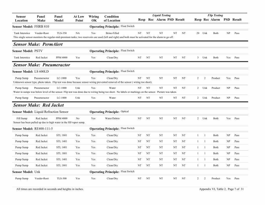
Sensor Location
Panel Make
Panel Model
At Low Point
Wiring OK
Condition of Location Resp Rec Alarm PSD Result Resp Rec PSD ResultAlarm
Liquid Testing Flip Testing
Sensor Model: FHRB 810 Operating Principle: Float Switch
Tank Interstice Veeder-Root TLS-350 NA Yes Brine-Filled NT NT NT NT NT 20 Unk NP PassBothThis single sensor monitors the regular-mid-premium tanks; two reservoirs are used (left and right) and both must be activated for the alarm to go off.
Sensor Make: PermAlertSensor Model: PSTV Operating Principle: Float Switch
Tank Interstice Red Jacket PPM 4000 Yes Yes Clean/Dry NT NT NT NT NT 3 Unk Yes PassBoth
Sensor Make: PneumeractorSensor Model: LS 600LD Operating Principle: Float Switch
Pump Sump Pneumeractor LC-1000 Yes Yes Clean/Dry NT NT NT NT NT 2 2 Yes PassProductUnknown sensor type, photo taken. Flip test was done because sensor wiring prevented removal of the sensor ( wiring too short).
Pump Sump Pneumeractor LC-1000 Unk Yes Water NT NT NT NT NT 2 Unk NP PassProductWater in sumps was below level of the sensor. Flip test was done due to wiring being too short. No labels or markings on the sensor. Picture was taken.
Pump Sump Pneumeractor LC-1000 Unk Yes Water NT NT NT NT NT 2 Unk NP PassProduct
Sensor Make: Red JacketSensor Model: Liquid Refraction Sensor Operating Principle: Optical
Fill Sump Red Jacket PPM 4000 No Yes Water/Debris NT NT NT NT NT 2 Unk Yes PassBothSensor has been pulled up due to high water in the fill/vapor sump.
Sensor Model: RE400-111-5 Operating Principle: Float Switch
Pump Sump Red Jacket STL 1801 Yes Yes Clean/Dry NT NT NT NT NT 1 1 NP PassBoth
Pump Sump Red Jacket STL 1401 Yes Yes Clean/Dry NT NT NT NT NT 1 1 NP PassBoth
Pump Sump Red Jacket STL 1401 Yes Yes Clean/Dry NT NT NT NT NT 1 1 NP PassBoth
Pump Sump Red Jacket STL 1801 Yes Yes Clean/Dry NT NT NT NT NT 1 1 NP PassBoth
Pump Sump Red Jacket STL 1401 Yes Yes Clean/Dry NT NT NT NT NT 1 1 NP PassBoth
Pump Sump Red Jacket STL 1801 Yes Yes Clean/Dry NT NT NT NT NT 1 1 NP PassBoth
Sensor Model: Unk Operating Principle: Float Switch
Pump Sump Veeder-Root TLS-300 Yes Yes Clean/Dry NT NT NT NT NT 2 2 Yes PassProduct
Page 7 of 31All times are recorded in seconds and heights in inches. Appendix VI, Table 2,

Sensor Location
Panel Make
Panel Model
At Low Point
Wiring OK
Condition of Location Resp Rec Alarm PSD Result Resp Rec PSD ResultAlarm
Liquid Testing Flip Testing
Sensor Make: RonanSensor Model: LS-3 Operating Principle: Float Switch
Fill Sump Ronan X76S Yes Yes Clean/Dry NT NT NT NT NT 1 1 NP FailBothFloat was stuck. Technician had to shake it to loosen it, then sensor went into alarm.
Fill Sump Ronan X761VCS-3LXi Yes Yes Clean/Dry NT NT NT NT NT 2 2 Yes PassProduct
Fill Sump Ronan X761VCS-3LXi Yes Yes Clean/Dry NT NT NT NT NT 2 2 Yes PassProduct
Fill Sump Ronan X76S Yes Yes Clean/Dry NT NT NT NT NT 1 1 Yes PassProduct
Fill Sump Ronan X76S Yes Yes Clean/Dry NT NT NT NT NT 1 1 Yes PassProduct
Fill Sump Ronan X76S Yes Yes Water NT NT NT NT NT 1 1 Yes PassProductSlight amount of water in fill sump. Not enough to activate an alarm.
Fill Sump Ronan X761VCS-3LXi Yes Yes Clean/Dry NT NT NT NT NT 2 2 Yes PassProduct
Fill Sump Ronan X76S Yes Yes Clean/Dry NT NT NT NT NT 1 1 NP PassBoth
Fill Sump Red Jacket PPM 4000 No Yes Water/Debris NT NT NT NT NT Unk Unk No FailNoneSensor appears to be good during a continuity test, but appears not to be hooked up to the control panel.
Monitoring Well EBW AutoStik Jr. 4 Yes Yes Backfill NT NT NT NT NT 1 1 NP PassProductSensor is a custom version of the LS3-A. It is made of stainless steel and is resistant to the chemicals stored in the system.
Monitoring Well EBW AutoStik Jr. 4 Yes Yes Backfill NT NT NT NT NT 1 1 NP PassProductSensor is a custom version of the LS3-A. It is made of stainless steel and is resistant to the chemicals stored in the system.
Monitoring Well EBW AutoStik Jr. 4 Yes Yes Backfill NT NT NT NT NT 1 1 NP PassProductSensor is a custom version of the LS3-A. It is made of stainless steel and is resistant to the chemicals stored in the system.
Monitoring Well EBW AutoStik Jr. 4 Yes Yes Backfill NT NT NT NT NT 1 1 NP PassProductSensor is a custom version of the LS3-A. It is made of stainless steel and is resistant to the chemicals stored in the system.
Monitoring Well EBW AutoStik Jr. 4 Yes Yes Backfill NT NT NT NT NT 1 1 NP PassProductSensor is a custom version of the LS3-A. It is made of stainless steel and is resistant to the chemicals stored in the system.
Monitoring Well EBW AutoStik Jr. 4 Yes Yes Backfill NT NT NT NT NT 1 1 NP PassProductSensor is a custom version of the LS3-A. It is made of stainless steel and is resistant to the chemicals stored in the system.
Monitoring Well EBW AutoStik Jr. 4 Yes Yes Backfill NT NT NT NT NT 1 1 NP PassProductSensor is a custom version of the LS3-A. It is made of stainless steel and is resistant to the chemicals stored in the system.
Monitoring Well EBW AutoStik Jr. 4 Yes Yes Backfill NT NT NT NT NT 1 1 NP PassProductSensor is a custom version of the LS3-A. It is made of stainless steel and is resistant to the chemicals stored in the system.
Page 8 of 31All times are recorded in seconds and heights in inches. Appendix VI, Table 2,

Sensor Location
Panel Make
Panel Model
At Low Point
Wiring OK
Condition of Location Resp Rec Alarm PSD Result Resp Rec PSD ResultAlarm
Liquid Testing Flip Testing
Pump Sump Ronan X76-4X Yes Yes Clean/Dry NT NT NT NT NT 1 1 NP PassBoth
Pump Sump Ronan X76S Yes Yes Water NT NT NT NT NT 2 2 NP PassBoth
Pump Sump Ronan X76S Yes Yes Clean/Dry NT NT NT NT NT 1 1 Yes PassProductFail-safe was verified operational.
Pump Sump Ronan X76VS Yes Yes Clean/Dry NT NT NT NT NT 2 1 Yes PassProduct
Pump Sump Ronan X76S Yes Yes Clean/Dry NT NT NT NT NT 1 1 Yes PassProductFail-safe was verified operational.
Pump Sump Ronan X76S Yes No Clean/Dry NT NT NT NT NT 3 NA Yes FailProductSensor would not come out of alarm after testing. Pump would not come on. Contractor repaired the facility. Problem was wiring inside the building, near the control panel.
Pump Sump Ronan X76S Yes Yes Water NT NT NT NT NT 1 1 Yes PassBoth
Pump Sump Ronan X76S Yes Yes Water NT NT NT NT NT 1 1 Yes PassBoth
Pump Sump Ronan X76S Yes Yes Clean/Dry NT NT NT NT NT 1 1 Yes PassProductFail-safe was verified operational.
Pump Sump Red Jacket PPM 4000 Yes No Water NT NT NT NT NT none NA No FailNoneSensor appeared to be functional when technician tested for continuity, but did not activate an alarm at the panel. Tech suspects problem with wiring between sensor and panel.
Pump Sump Ronan Unk Yes Yes Clean/Dry NT NT NT NT NT 2 2 NP PassUnkThis site has a suction system and a tank sump.
Pump Sump Ronan X761VCS-3LXi Yes Yes Clean/Dry NT NT NT NT NT 2 2 Yes PassProduct
Pump Sump Red Jacket PPM 4000 Yes Yes Clean/Dry NT NT NT NT NT 3 Unk Yes PassBothAfter follow up with local agency, inspector confirmed that the technician replaced fill sump sensor and replaced the broken wire in the monitor.
Pump Sump Ronan X76LVC Yes Yes Clean/Dry NT NT NT NT NT 1 1 Yes PassProduct
Pump Sump Ronan X76LVC Yes Yes Clean/Dry NT NT NT NT NT 1 1 Yes PassProduct
Pump Sump Ronan X76VS Yes Yes Clean/Dry NT NT NT NT NT 2 1 Yes PassProduct
Pump Sump Ronan X76S Yes Yes Water NT NT NT NT NT 1 2 NP PassBoth
Pump Sump Ronan X76S Yes Yes Water NT NT NT NT NT 2 2 NP PassBoth
Pump Sump Ronan X76VS Yes Yes Clean/Dry NT NT NT NT NT 2 1 Yes PassProductSensor was on its side and slightly upside-down, but not in alarm. Sensor did alarm when fully flipped over. Tech re-installed sensor properly after testing.
Pump Sump Ronan X76LVC Yes Yes Clean/Dry NT NT NT NT NT 5 5 NP PassProduct
Pump Sump Ronan X761VCS-3LXi Yes Yes Water NT NT NT NT NT 2 2 Yes PassProduct
Pump Sump Ronan X76LVC Yes Yes Clean/Dry NT NT NT NT NT 1 1 Yes PassProduct
Page 9 of 31All times are recorded in seconds and heights in inches. Appendix VI, Table 2,

Sensor Location
Panel Make
Panel Model
At Low Point
Wiring OK
Condition of Location Resp Rec Alarm PSD Result Resp Rec PSD ResultAlarm
Liquid Testing Flip Testing
Pump Sump Ronan X76S Yes Yes Water NT NT NT NT NT 2 2 NP PassBoth
Pump Sump Ronan X76LVC Yes Yes Clean/Dry NT NT NT NT NT 5 5 NP PassProduct
Pump Sump Ronan X761VCS-3LXi Yes Yes Clean/Dry NT NT NT NT NT 2 2 Yes PassProduct
Pump Sump Ronan X76-4X Yes Yes Clean/Dry NT NT NT NT NT 1 1 NP PassBoth
Pump Sump Ronan X76-4X Yes Yes Clean/Dry NT NT NT NT NT 1 1 NP PassBoth
Tank Interstice Ronan X76S Yes Yes Clean/Dry NT NT NT NT NT 2 2 NP PassProduct
Tank Interstice Ronan X76LVC Yes Yes Clean/Dry NT NT NT NT NT 1 1 NP PassProduct
Tank Interstice Ronan X76S Yes Yes Clean/Dry NT NT NT NT NT 1 1 NP PassBoth
Tank Interstice Ronan X76S Yes Yes Clean/Dry NT NT NT NT NT 1 1 NP PassBoth
Tank Interstice Red Jacket PPM 4000 Yes Yes Clean/Dry NT NT NT NT NT 3 Unk Yes PassBoth
Tank Interstice Ronan X76S Yes Yes Clean/Dry NT NT NT NT NT 2 2 NP PassProduct
Tank Interstice Ronan X76S Yes Yes Clean/Dry NT NT NT NT NT 1 1 NP PassBoth
UDC Ronan X76-4X Yes Yes Clean/Dry NT NT NT NT NT 1 1 NP PassBoth
UDC Ronan X76-4X Yes Yes Clean/Dry NT NT NT NT NT 1 1 NP PassBoth
UDC Ronan X76-4X Yes Yes Clean/Dry NT NT NT NT NT 1 1 NP PassBoth
UDC Ronan X76-4X Yes Yes Clean/Dry NT NT NT NT NT 1 1 NP PassBoth
UDC Ronan X76-4X Yes Yes Clean/Dry NT NT NT NT NT 1 11 NP PassBoth
UDC Ronan X76-4X Yes Yes Clean/Dry NT NT NT NT NT 1 1 NP PassBoth
UDC Ronan X76-4X Yes Yes Clean/Dry NT NT NT NT NT 1 1 NP PassBoth
UDC Ronan X76-4X Yes Yes Clean/Dry NT NT NT NT NT 1 1 NP PassBoth
Sensor Model: LS-30 Operating Principle: Float Switch
Tank Interstice Ronan X76S NA Yes Brine-Filled NT NT NT NT NT 2 2 NP PassBoth
Tank Interstice Ronan X76S NA Yes Brine-Filled NT NT NT NT NT 2 2 NP PassBoth
Tank Interstice Ronan Unk NA Yes Unk 3 3 Water NA Pass NT NT NT NTNTRonan- LS-30 hydrostatic in generator tank.
Tank Interstice Ronan X76S NA Yes Brine-Filled NT NT NT NT NT 2 2 NP PassBoth
Tank Interstice Ronan X76S NA Yes Brine-Filled NT NT NT NT NT 2 2 NP PassBoth
Page 10 of 31All times are recorded in seconds and heights in inches. Appendix VI, Table 2,

Sensor Location
Panel Make
Panel Model
At Low Point
Wiring OK
Condition of Location Resp Rec Alarm PSD Result Resp Rec PSD ResultAlarm
Liquid Testing Flip Testing
Sensor Model: LS-7 Operating Principle: Float Switch
Tank Interstice Ronan X76S Yes Yes Clean/Dry NT NT NT NT NT 1 1 NP PassProductTechnician pulled wire and pull string at the same time. This lifts the sensor off the bottom of the tank interstice and allows the float to fall, activating the alarm.
Tank Interstice Ronan X76S Yes Yes Clean/Dry NT NT NT NT NT 1 1 NP PassProductTechnician pulled wire and pull string at the same time. This lifts the sensor off the bottom of the tank interstice and allows the float to fall, activating the alarm.
Tank Interstice Ronan X76S Yes Yes Clean/Dry NT NT NT NT NT 1 1 NP PassProductTechnician pulled wire and pull string at the same time. This lifts the sensor off the bottom of the tank interstice and allows the float to fall, activating the alarm.
Tank Interstice Ronan X76S Yes Yes Clean/Dry NT NT NT NT NT 3 1 NP PassProduct
Tank Interstice Ronan X76S Yes Yes Clean/Dry NT NT NT NT NT 3 1 NP PassProduct
Tank Interstice Ronan X76LVC Yes Yes Clean/Dry NT NT NT NT NT 4 4 NP PassProduct
Tank Interstice Ronan X76-4X Yes Yes Clean/Dry NT NT NT NT NT 1 1 NP PassBoth
Tank Interstice Ronan X76VS Yes Yes Clean/Dry NT NT NT NT NT 1 1 NP PassProductAlarm was activated by shaking sensor while still in tank interstice.
Tank Interstice Ronan X76LVC No Yes Clean/Dry NT NT NT NT NT 5 5 NP PassProductThe sensor could not be taken out of the tank interstice; therefore the sensor was activated within the tank.
Tank Interstice Ronan X76VS Yes Yes Clean/Dry NT NT NT NT NT 1 1 NP PassProductSensor had to be re-installed with a fish-tape because the string was broken. This took the contractor about 1 hour.
Tank Interstice Ronan X76S Yes Yes Clean/Dry NT NT NT NT NT 3 1 NP PassProduct
Tank Interstice Ronan X76LVC Yes Yes Clean/Dry NT NT NT NT NT 5 5 NP PassProduct
Tank Interstice Ronan X76VS Yes Yes Clean/Dry NT NT NT NT NT 1 1 NP PassProductAlarm was activated by shaking sensor while still in tank interstice.
Tank Interstice Ronan X76LVC Yes Yes Clean/Dry NT NT NT NT NT 3 3 NP PassProduct
Tank Interstice Ronan X76-4X Yes Yes Clean/Dry NT NT NT NT NT 1 1 NP PassBoth
Tank Interstice Ronan X76-4X Yes Yes Clean/Dry NT NT NT NT NT 1 1 NP PassBoth
Tank Interstice Ronan X76LVC NA Yes Clean/Dry NT NT NT NT NT 5 5 NP PassProduct
Tank Interstice Ronan X76VS Yes Yes Clean/Dry NT NT NT NT NT 1 1 NP PassProductAlarm was activated by shaking sensor while still in tank interstice.
Sensor Model: Unk Operating Principle: Float Switch
Tank Interstice Veeder-Root TLS-300 NA Yes Clean/Dry NT NT NT NT NT 2 2 Yes PassProduct
Page 11 of 31All times are recorded in seconds and heights in inches. Appendix VI, Table 2,

Sensor Location
Panel Make
Panel Model
At Low Point
Wiring OK
Condition of Location Resp Rec Alarm PSD Result Resp Rec PSD ResultAlarm
Liquid Testing Flip Testing
Sensor Make: UniversalSensor Model: LALS-1 Operating Principle: Thermal Conductivity
Fill Sump Universal Leak Alert LA-08 Yes Yes Clean/Dry 1 Unk Both Yes Pass NA NA NA NANASensor activates an audible alarm and shuts down pump at the dispenser.
Fill Sump Universal Leak Alert LA-08 Yes Yes Clean/Dry 1 Unk Both Yes Pass NA NA NA NANASensor activates an audible alarm and shuts down pump at the dispenser.
Piping Sump Universal Leak Alert LA-08 Yes Yes Clean/Dry 1 Unk Both Yes Pass NA NA NA NANASensor activates an audible alarm and shuts down pump at the dispenser.
Pump Sump Universal Leak Alert LA-08 Yes Yes Clean/Dry 2 Unk Product NA Pass NA NA NA NANA
Pump Sump Universal Leak Alert LA-08 Yes Yes Clean/Dry 3 2 Water Yes Pass NA NA NA NANA
Pump Sump Universal Leak Alert LA-08 Yes Yes Clean/Dry 2 2 Water Yes Pass NA NA NA NANA
Pump Sump Universal Leak Alert LA-08 Yes Yes Vapor Odor NT NT NT NT NT 1 1 NP PassProductContractor blows on the sensor to activate the alarm. Sensor responds instantly. Sumps had been recently refinished and had strong chemical smell, not fuel.
Pump Sump Universal Leak Alert LA-08 Yes Yes Clean/Dry 2 Unk Product NA Pass NA NA NP NANA
Pump Sump Universal Leak Alert LA-08 Yes Yes Vapor Odor NT NT NT NT NT 1 1 NP PassProductContractor blows on the sensor to activate the alarm. Sensor responds instantly. Sumps had been recently refinished and had strong chemical smell, not fuel.
Pump Sump Universal Leak Alert LA-08 Yes Yes Clean/Dry 2 Unk Product NA Pass NA NA NA NANA
Tank Interstice Universal Leak Alert LA-08 Yes Yes Clean/Dry 8 10 Water Yes Pass NA NA NA NANA
Tank Interstice Universal Leak Alert LA-08 Yes Yes Clean/Dry 15 15 Water NA Pass NA NA NA NANAEmergency generator with 1000 gallon tank.
Tank Interstice Universal Leak Alert LA-08 Yes Yes Clean/Dry 5 3 Water Yes Pass NA NA NA NANA
Tank Interstice Universal Leak Alert LA-08 Yes Yes Clean/Dry 4 4 Water Yes Pass NA NA NA NANA
Tank Interstice Universal Leak Alert LA-08 Yes Yes Clean/Dry NT NT NT NT NT 3 3 NA PassWaterContractor blows on the sensor to activate the alarm.
Tank Interstice Universal Leak Alert LA-08 Yes Yes Clean/Dry NT NT NT NT NT 1 1 NA PassProductContractor blows on the sensor to activate the alarm. Sensor responds instantly.
Tank Interstice Universal Leak Alert LA-08 Yes Yes Clean/Dry NT NT NT NT NT 1 1 NA PassProductContractor blows on the sensor to activate the alarm. Sensor responds instantly.
Tank Interstice Universal Leak Alert LA-08 Yes Yes Clean/Dry NT NT NT NT NT 1 1 NA PassProductContractor blows on the sensor to activate the alarm. Sensor responds instantly.
Page 12 of 31All times are recorded in seconds and heights in inches. Appendix VI, Table 2,

Sensor Location
Panel Make
Panel Model
At Low Point
Wiring OK
Condition of Location Resp Rec Alarm PSD Result Resp Rec PSD ResultAlarm
Liquid Testing Flip Testing
Tank Interstice Universal Leak Alert LA-08 Yes Yes Clean/Dry 2 Unk Product NA Pass NA NA NA NANA
Tank Interstice Universal Leak Alert LA-08 Yes Yes Clean/Dry 2 Unk Product NA Pass NA NA NA NANA
Tank Interstice Universal Leak Alert LA-08 Yes Yes Clean/Dry NT NT NT NT NT 2 2 NA PassBothContractor blows on the sensor to activate the alarm.
Tank Interstice Universal Leak Alert LA-08 Yes Yes Clean/Dry NT NT NT NT NT 3 3 NA PassWaterContractor blows on the sensor to activate the alarm.
Tank Interstice Universal Leak Alert LA-08 Yes Yes Clean/Dry 3 3 None Yes Pass NA NA NA NANA
Tank Interstice Universal Leak Alert LA-08 Yes Yes Clean/Dry NT NT NT NT NT 3 3 NA PassWaterContractor blows on the sensor to activate the alarm.
Tank Interstice Universal Leak Alert LA-08 Yes Yes Clean/Dry 1 Unk Both Yes Pass NA NA NA NANASensor activates an audible alarm and shuts down pump at the dispenser.
Tank Interstice Universal Leak Alert LA-08 Yes Yes Clean/Dry 1 Unk Both Yes Pass NA NA NA NANASensor activates an audible alarm and shuts down pump at the dispenser.
Tank Interstice Universal Leak Alert LA-08 Yes Yes Clean/Dry NT NT NT NT NT None None NA FailNoneContractor waited for 2 minutes for the sensor to response, but never did. Sensor had to be replaced.
Tank Interstice Universal Leak Alert LA-08 Yes Yes Clean/Dry None NA None No Fail NA NA NA NANASensor was not tested because it was stuck in the interstitial space.
Tank Interstice Universal Leak Alert LA-08 Yes Yes Clean/Dry 2 Unk Product NA Pass NA NA NA NANA
Sensor Model: LAVS-1 Operating Principle: Metal Oxide Semiconductor
Tank Interstice Universal Leak Alert LA-08 Yes Yes Clean/Dry Unk Unk Unk No Fail NA NA NA NANA
Sensor Model: LS 03875 STP Sensor Operating Principle: Thermal Conductivity
Pump Sump Universal Leak Alert LA-08 Yes Yes Clean/Dry 2 33 Product Yes Pass NA NA NP NANAThere was no light bulb on the monitoring panel, but alarm activated.
Pump Sump Universal Leak Alert LA-08 Yes Yes Clean/Dry 2 11 Product Yes Pass NA NA NA NANAThere was no light bulb on the monitoring panel, but alarm activated.
Pump Sump Universal Leak Alert LA-08 Yes Yes Clean/Dry 2 15 Product Yes Pass NA NA NP NANAThere was no light bulb on the monitoring panel, but alarm activated.
Sensor Make: Veeder-RootSensor Model: 330212-001 Operating Principle: Float Switch
UDC Veeder-Root Dispenser cut-off Yes Yes Clean/Dry NT NT NT NT NT 2 2 Yes PassProduct
Page 13 of 31All times are recorded in seconds and heights in inches. Appendix VI, Table 2,

Sensor Location
Panel Make
Panel Model
At Low Point
Wiring OK
Condition of Location Resp Rec Alarm PSD Result Resp Rec PSD ResultAlarm
Liquid Testing Flip Testing
UDC Veeder-Root Dispenser cut-off Yes Yes Clean/Dry NT NT NT NT NT 1 MR NP PassBothSensor cuts power to dispenser, which must be manually reset.
UDC Veeder-Root Dispenser cut-off Yes Yes Clean/Dry NT NT NT NT NT 2 1 Yes PassProduct
UDC Veeder-Root Dispenser cut-off Yes Yes Clean/Dry NT NT NT NT NT 2 2 Yes PassProduct
UDC Veeder-Root Dispenser cut-off Yes Yes Clean/Dry NT NT NT NT NT 2 2 Yes PassProduct
UDC Veeder-Root Dispenser cut-off Yes Yes Clean/Dry NT NT NT NT NT 1 MR NP PassBothSensor cuts power to dispenser, which must be manually reset.
UDC Veeder-Root Dispenser cut-off Yes Yes Clean/Dry NT NT NT NT NT 10 MR NP PassBothSensor cuts power to dispenser, which must be manually reset.
Sensor Model: 331102-002 Operating Principle: Float Switch
Pump Sump Veeder-Root TLS-350 Yes Yes Clean/Dry NT NT NT NT NT 8 1 Yes PassBothSensor has double float alarm (high/low). Service technician decided only to do the flip test.
Pump Sump Veeder-Root TLS-350 Yes Yes Clean/Dry NT NT NT NT NT 5 1 Yes PassBothSensor has double float alarm (high/low). Service technician decided only to do the flip test.
Sensor Model: 794380-208 Operating Principle: Float Switch
ATG Sump Veeder-Root TLS-350 Yes Yes Water NT NT NT NT NT Unk Unk NP PassProductSump contains dirty water. Alarm was set at the control panel.
ATG Sump Veeder-Root TLS-350 Yes Yes Water NT NT NT NT NT Unk Unk NP PassProductSump contains dirty water. Alarm was set at the control panel.
ATG Sump Veeder-Root TLS-350 Yes Yes Water NT NT NT NT NT Unk Unk NP PassProductSump contains dirty water. Alarm was set at the control panel
ATG Sump Veeder-Root TLS-350 Yes Yes Clean/Dry NT NT NT NT NT 5 1 Yes PassProduct
ATG Sump Veeder-Root TLS-350 Yes Yes Clean/Dry NT NT NT NT NT 5 1 Yes PassProduct
ATG Sump Veeder-Root TLS-350 Yes Yes Clean/Dry NT NT NT NT NT 5 1 Yes PassProduct
Fill Sump Veeder-Root TLS-350 Yes Yes Water NT NT NT NT NT 3 3 Yes PassProductFill sump contains water, dirt, and corrosion.
Fill Sump Veeder-Root TLS-350 Yes Yes Debris NT NT NT NT NT 3 2 NP PassProduct
Fill Sump Veeder-Root TLS-350 Yes Yes Product NT NT NT NT NT 2 2 NP PassProductSensor was in alarm when technician arrived to conduct inspection. Technician called to have the product removed.
Fill Sump Veeder-Root TLS-350 No Yes Water NT NT NT NT NT 2 2 NP PassProduct
Page 14 of 31All times are recorded in seconds and heights in inches. Appendix VI, Table 2,

Sensor Location
Panel Make
Panel Model
At Low Point
Wiring OK
Condition of Location Resp Rec Alarm PSD Result Resp Rec PSD ResultAlarm
Liquid Testing Flip Testing
Fill Sump Veeder-Root TLS-350 No Yes Product NT NT NT NT NT 2 2 NP PassProduct
Fill Sump Veeder-Root TLS-350 Yes Yes Clean/Dry NT NT NT NT NT 2 2 Yes PassProduct
Fill Sump Veeder-Root TLS-350 Yes Yes Water NT NT NT NT NT 10 2 Yes PassProduct
Fill Sump Veeder-Root TLS-350 Yes Yes Debris NT NT NT NT NT 2 2 NP PassProduct
Fill Sump Veeder-Root TLS-350 Yes Yes Clean/Dry 5 Unk Product NA Pass NT NT NT NTNT
Fill Sump Veeder-Root TLS-350 Yes Yes Product NT NT NT NT NT 8 Unk NP PassProductFill sump contains waste oil.
Fill Sump Veeder-Root TLS-350 Yes Yes Product NT NT NT NT NT 8 Unk NP PassProduct
Fill Sump Veeder-Root TLS-350 Yes Yes Product NT NT NT NT NT 8 Unk NP PassProduct
Fill Sump Veeder-Root TLS-350 Yes Yes Product NT NT NT NT NT 8 Unk NP PassProduct
Fill Sump Veeder-Root TLS-350 Yes Yes Clean/Dry 10 5 Product Yes Pass NT NT NT NTNT
Fill Sump Veeder-Root TLS-350 Yes Yes Clean/Dry 5 5 Product Yes Pass NT NT NT NTNT
Fill Sump Veeder-Root TLS-350 Yes Yes Clean/Dry 8 5 Product Yes Pass NT NT NT NTNT
Fill Sump Veeder-Root TLS-350 Yes Yes Clean/Dry 5 5 Product Yes Pass NT NT NT NTNT
Fill Sump Veeder-Root TLS-350 Yes Yes Clean/Dry 5 5 Product Yes Pass NT NT NT NTNT
Fill Sump Veeder-Root TLS-350 No Yes Clean/Dry NT NT NT NT NT 1 1 NP PassBoth
Fill Sump Veeder-Root TLS-350 No Yes Clean/Dry NT NT NT NT NT 1 1 NP PassBoth
Fill Sump Veeder-Root TLS-350 Yes Yes Water NT NT NT NT NT none NA No FailNoneTechnician waited for over 2 minutes, but sensor did not alarm. Finally inspector decided to call the test off and replace the sensor. Testing was done on the new sensor and it passed.
Fill Sump Veeder-Root TLS-350 No Yes Clean/Dry NT NT NT NT NT 1 1 NP PassBoth
Fill Sump Veeder-Root TLS-350 Yes Yes Clean/Dry NT NT NT NT NT 5 1 Yes PassProduct
Fill Sump Veeder-Root TLS-350 Yes Yes Water NT NT NT NT NT 5 1 Yes PassProduct
Fill Sump Veeder-Root Unk Yes Yes Clean/Dry NT NT NT NT NT 5 6 NP PassProduct
Fill Sump Veeder-Root TLS-350 Yes Yes Clean/Dry NT NT NT NT NT 12 2 Yes PassProduct
Fill Sump Veeder-Root TLS-350 No Yes Water NT NT NT NT NT 15 1 Yes PassProductThe sensor was not located at the lowest point in the tank. Technician lowered it and activetd an alarm.
Fill Sump Veeder-Root Unk Yes Yes Water NT NT NT NT NT 5 6 Yes PassProduct
Page 15 of 31All times are recorded in seconds and heights in inches. Appendix VI, Table 2,

Sensor Location
Panel Make
Panel Model
At Low Point
Wiring OK
Condition of Location Resp Rec Alarm PSD Result Resp Rec PSD ResultAlarm
Liquid Testing Flip Testing
Fill Sump Veeder-Root TLS-350 No Yes Water NT NT NT NT NT 5 1 NP PassProductContains a substantial amount of water.
Fill Sump Veeder-Root Unk Yes Yes Clean/Dry NT NT NT NT NT 5 6 Yes PassProduct
Fill Sump Veeder-Root TLS-350 Yes Yes Clean/Dry NT NT NT NT NT 5 1 Yes PassProductThe sensor was not at the lowest point in the tank.
Fill Sump Veeder-Root Unk Yes Yes Water NT NT NT NT NT 5 5 Yes PassProductSump has 4-5 inches of water. Technician was waiting for maintinance to clean the water before putting back the sensor.
Fill Sump Veeder-Root Unk Yes Yes Water NT NT NT NT NT 5 5 Yes PassProductSump has 4-5 inches of water. Technician was waiting for maintinance to clean the water before putting back the sensor.
Piping Sump Veeder-Root TLS-350 Yes Yes Clean/Dry NT NT NT NT NT 6 4 Yes PassProduct
Pump Sump Veeder-Root TLS-350 Yes Yes Clean/Dry NT NT NT NT NT Unk Unk NP PassProductAlarm was set at the control panel.
Pump Sump Veeder-Root TLS-350 Yes Yes Water 5 2 Product Yes Pass NT NT NT NTNT
Pump Sump Veeder-Root TLS-350 Yes Yes Water 5 2 Product Yes Pass NT NT NT NTNT
Pump Sump Veeder-Root TLS-350 Yes Yes Water 5 2 Product Yes Pass NT NT NT NTNT
Pump Sump Veeder-Root TLS-350 Yes Yes Water NT NT NT NT NT 10 10 NP PassProductFlip Test- estimated response of 10 seconds.
Pump Sump Veeder-Root TLS-350 Yes Yes Clean/Dry NT NT NT NT NT 10 10 NP PassProductFlip Test- estimated response of 10 seconds
Pump Sump Veeder-Root TLS-350 Yes Yes Clean/Dry NT NT NT NT NT Unk Unk NP PassProductAlarm was set at the control panel.
Pump Sump Veeder-Root TLS-350 Yes Yes Clean/Dry NT NT NT NT NT 8 2 Yes PassProduct
Pump Sump Veeder-Root TLS-350 Yes Yes Water NT NT NT NT NT 6 2 Yes PassProduct
Pump Sump Veeder-Root TLS-350 Yes Yes Clean/Dry 5 5 Product Yes Pass NT NT NT NTNT
Pump Sump Veeder-Root TLS-350 Yes Yes Product NT NT NT NT NT 5 2 Yes PassProduct
Pump Sump Veeder-Root TLS-350 Yes Yes Clean/Dry NT NT NT NT NT 10 5 Yes PassProduct
Pump Sump Veeder-Root TLS-350 Yes Yes Clean/Dry NT NT NT NT NT 5 5 Yes PassProductThe cable is too short to test sensor in liquid, Instead perform a flip test.
Pump Sump Veeder-Root TLS-350 Yes Yes Clean/Dry NT NT NT NT NT 8 2 Yes PassProduct
Page 16 of 31All times are recorded in seconds and heights in inches. Appendix VI, Table 2,

Sensor Location
Panel Make
Panel Model
At Low Point
Wiring OK
Condition of Location Resp Rec Alarm PSD Result Resp Rec PSD ResultAlarm
Liquid Testing Flip Testing
Pump Sump Veeder-Root TLS-350 Yes Yes Clean/Dry NT NT NT NT NT 10 10 NP PassProductFlip Test- estimated response of 10 seconds
Pump Sump Veeder-Root TLS-350 No Yes Clean/Dry NT NT NT NT NT 1 1 NP PassBoth
Pump Sump Veeder-Root TLS-350 Yes Yes Water NT NT NT NT NT 5 1 Yes PassProduct
Pump Sump Veeder-Root TLS-350 No Yes Product NT NT NT NT NT 5 1 Yes PassProduct
Pump Sump Veeder-Root TLS-350 Yes Yes Clean/Dry NT NT NT NT NT 5 1 Yes PassProduct
Pump Sump Veeder-Root TLS-350 Yes Yes Clean/Dry NT NT NT NT NT 5 1 Yes PassProduct
Pump Sump Veeder-Root TLS-350 Yes Yes Clean/Dry 10 4 Product Yes Pass NT NT NT NTNT
Pump Sump Veeder-Root TLS-350 Yes Yes Clean/Dry 12 4 Product Yes Pass NT NT NT NTNT
Pump Sump Veeder-Root TLS-350 Yes Yes Clean/Dry NT NT NT NT NT Unk Unk NP PassProductAlarm was set at the control panel.
Pump Sump Veeder-Root TLS-350 No Yes Clean/Dry NT NT NT NT NT 1 1 NP PassBoth
Pump Sump Veeder-Root TLS-350 Yes Yes Clean/Dry NT NT NT NT NT 8 4 Yes PassProduct
Pump Sump Veeder-Root TLS-350 Yes Yes Clean/Dry 10 4 Product Yes Pass NT NT NT NTNT
Pump Sump Veeder-Root TLS-350 Yes Yes Clean/Dry NT NT NT NT NT 6 4 Yes PassProduct
Pump Sump Veeder-Root TLS-350 No Yes Clean/Dry NT NT NT NT NT 1 1 NP PassBoth
Pump Sump Unk Unk Yes Yes Clean/Dry NT NT NT NT NT 6 6 Yes PassProduct
Pump Sump Veeder-Root TLS-350 Yes Yes Clean/Dry 5 5 Product Yes Pass NT NT NT NTNT
Pump Sump Veeder-Root TLS-350 Yes Yes Clean/Dry NT NT NT NT NT 2 Unk Yes PassProduct
Pump Sump Veeder-Root TLS-350 Yes Yes Clean/Dry NT NT NT NT NT 2 Unk Yes PassProduct
Pump Sump Veeder-Root TLS-350 Yes Yes Clean/Dry 8 4 Product Yes Pass NT NT NT NTNT
Pump Sump Veeder-Root TLS-350 Yes Yes Clean/Dry NT NT NT NT NT 10 15 Yes PassProduct
Pump Sump Veeder-Root TLS-350 Yes Yes Clean/Dry 7 5 Product Yes Pass NT NT NT NTNT
Pump Sump Veeder-Root TLS-350 Yes Yes Clean/Dry 10 5 Product Yes Pass NT NT NT NTNT
Pump Sump Veeder-Root TLS-350 Yes Yes Clean/Dry NT NT NT NT NT 5 5 Yes PassProductCable was too short to allow for testing in liquid. Flip test was used.
Pump Sump Veeder-Root TLS-350 Yes Yes Clean/Dry NT NT NT NT NT 5 5 Yes PassProductCable was too short to allow for testing in liquid. Flip test was used.
Page 17 of 31All times are recorded in seconds and heights in inches. Appendix VI, Table 2,

Sensor Location
Panel Make
Panel Model
At Low Point
Wiring OK
Condition of Location Resp Rec Alarm PSD Result Resp Rec PSD ResultAlarm
Liquid Testing Flip Testing
Pump Sump Veeder-Root TLS-350 Yes Yes Clean/Dry NT NT NT NT NT 5 5 Yes PassProductCable was too short to allow for testing in liquid. Flip test was used.
Pump Sump Veeder-Root TLS-350 Yes Yes Clean/Dry NT NT NT NT NT Unk Unk Unk PassProductTested 4 of VR 208 sensors, all 4 alarms were set.
Pump Sump Veeder-Root TLS-350 Yes Yes Clean/Dry NT NT NT NT NT Unk Unk Unk PassProduct
Pump Sump Veeder-Root TLS-350 Yes Yes Clean/Dry NT NT NT NT NT Unk Unk Unk PassProduct
Pump Sump Veeder-Root Unk Yes Yes Water NT NT NT NT NT 5 6 Yes PassProduct
Pump Sump Veeder-Root TLS-350 Yes Yes Clean/Dry NT NT NT NT NT 10 15 Yes PassProduct
Pump Sump Veeder-Root TLS-350 No Yes Product NT NT NT NT NT 3 3 NP PassProduct2-3 gallons of product in the sump. Sensor was raised above the product level. Sensor in pump sump was not programmed to shut down pump.
Pump Sump Veeder-Root Unk No Yes Water 25 17 Water Yes Pass NT NT NT NTNTFill bucket was detached. Stick was in the product line (to prevent the flapper from shutting down the flow)
Pump Sump Veeder-Root Unk No Yes Water 20 20 Water Yes Pass NT NT NT NTNTFill bucket was detached. Stick was in the product line (to prevent the flapper from shutting down the flow)
Pump Sump Veeder-Root Unk No Yes Water 20 20 Water Yes Pass NT NT NT NTNTFill bucket was detached. Stick was in the product line (to prevent the flapper from shutting down the flow)
Pump Sump Veeder-Root Unk No Yes Water 20 15 Water Yes Pass NT NT NT NTNTSensor timed out & Technician had to go and re-set it to shut down the pump.
Pump Sump Veeder-Root Unk No Yes Water 25 30 Water Yes Pass NT NT NT NTNTSensor timed out & Technician had to go and re-set it to shut down the pump.
Pump Sump Veeder-Root Unk No Yes Water 20 30 Water Yes Pass NT NT NT NTNTSensor timed out & Technician had to go and re-set it to shut down the pump.
Pump Sump Veeder-Root Unk No Yes Water 20 20 Water Yes Pass NT NT NT NTNTSensor timed out & Technician had to go and re-set it to shut down the pump.
Pump Sump Veeder-Root Unk No Yes Water 20 15 Water Yes Pass NT NT NT NTNTFill bucket was detached. Stick was in the product line (to prevent the flapper from shutting down the flow). Most of sensors timed out & Technician had to go and re-set it to shut down the pump.
Pump Sump Veeder-Root TLS-350 Yes Yes Clean/Dry NT NT NT NT NT Unk Unk Unk PassProduct
Pump Sump Veeder-Root TLS-350 Yes Yes Clean/Dry NT NT NT NT NT 3 5 Yes PassProduct
Pump Sump Veeder-Root TLS-350 Yes Yes Clean/Dry NT NT NT NT NT 3 3 Yes PassProduct
Pump Sump Veeder-Root TLS-350 Yes Yes Clean/Dry NT NT NT NT NT 2 2 Yes PassProduct
Pump Sump Veeder-Root TLS-350 Yes Yes Clean/Dry NT NT NT NT NT 5 5 Yes PassProduct
Page 18 of 31All times are recorded in seconds and heights in inches. Appendix VI, Table 2,

Sensor Location
Panel Make
Panel Model
At Low Point
Wiring OK
Condition of Location Resp Rec Alarm PSD Result Resp Rec PSD ResultAlarm
Liquid Testing Flip Testing
Pump Sump Veeder-Root TLS-350 Yes Yes Clean/Dry NT NT NT NT NT 5 5 Yes PassProduct
Pump Sump Veeder-Root TLS-350 Yes Yes Clean/Dry NT NT NT NT NT 5 5 Yes PassProduct
Pump Sump Veeder-Root TLS-350 No Yes Water NT NT NT NT NT 2 Unk Yes PassProduct2 sensors, 1 raised in sump and the other was a the lowest point. Both responded and activated pump shut off. Picture of sensor was taken.
Pump Sump Veeder-Root TLS-350 Yes Yes Water NT NT NT NT NT 2 Unk Yes PassProduct
Pump Sump Veeder-Root TLS-350 Yes Yes Clean/Dry NT NT NT NT NT 5 5 Yes PassProduct
Pump Sump Veeder-Root TLS-350 Yes Yes Clean/Dry 15 5 Product Yes Pass NT NT NT NTNT
Pump Sump Veeder-Root TLS-350 No Yes Clean/Dry NT NT NT NT NT 5 5 Yes PassProductSensor was raised about 4 inches from the bottom of the sump.
Pump Sump Veeder-Root TLS-350 No Yes Product NT NT NT NT NT 3 3 NP PassProduct2-3 gallons of product in the sump. Sensor was raised above the product level. Sensor in pump sump was not programmed to shut down pump.
Pump Sump Veeder-Root TLS-350 Yes Yes Clean/Dry NT NT NT NT NT 15 10 Yes PassProduct
Pump Sump Veeder-Root TLS-350 Yes Yes Clean/Dry NT NT NT NT NT 12 10 Yes PassProduct
Pump Sump Veeder-Root TLS-350 Yes Yes Clean/Dry NT NT NT NT NT 10 10 Yes PassProduct
Pump Sump Veeder-Root TLS-350 No Yes Product NT NT NT NT NT 8 10 Yes PassProductProduct is leaking out of the top of the turbine pump.
Pump Sump Veeder-Root TLS-350 No Yes Product NT NT NT NT NT 8 10 Yes PassProductProduct is leaking out of the top of the turbine pump.
Pump Sump Veeder-Root TLS-350 No Yes Product NT NT NT NT NT 8 10 Yes PassProductProduct is leaking out of the top of the turbine pump.
Pump Sump Veeder-Root TLS-350 Yes Yes Clean/Dry NT NT NT NT NT 6 Unk Yes PassProduct
Pump Sump Veeder-Root TLS-350 Yes Yes Clean/Dry NT NT NT NT NT 6 Unk Yes PassProduct
Pump Sump Veeder-Root TLS-350 Yes Yes Clean/Dry NT NT NT NT NT 10 15 Yes PassProduct
Pump Sump Veeder-Root TLS-350 Yes Yes Clean/Dry NT NT NT NT NT 3 5 Yes PassProduct
Pump Sump Veeder-Root TLS-350 Yes Yes Clean/Dry NT NT NT NT NT 4 4 Yes PassProductNoticed a 1" hole in the sump, which will need to be repaired in order to have tight secondary containment.
Pump Sump Gilbarco EMC Yes Yes Clean/Dry NT NT NT NT NT 5 5 Yes PassProduct
Pump Sump Veeder-Root TLS-300 Yes Yes Clean/Dry NT NT NT NT NT 30 Unk NP PassProduct
Page 19 of 31All times are recorded in seconds and heights in inches. Appendix VI, Table 2,

Sensor Location
Panel Make
Panel Model
At Low Point
Wiring OK
Condition of Location Resp Rec Alarm PSD Result Resp Rec PSD ResultAlarm
Liquid Testing Flip Testing
Pump Sump Veeder-Root TLS-350 No Yes Clean/Dry NT NT NT NT NT 4 5 Yes PassProductThere was a hole in the sump, approximately 1 1/2" diam. Electrical wiring below penetration lines. Hydrostatic test was performed to the highest penetration lines at 16 minutes per cycle.Test at 16 psi and fail if below 12 psi. Fill sump is not clean..
Pump Sump Veeder-Root TLS-350 No Yes Clean/Dry NT NT NT NT NT er 2 m NA No FailNoneThe contractor decided to stop testing the sensor after it failed to respond for more than 2 minutes and replace it with a new sensor.
Pump Sump Veeder-Root TLS-350 Yes Yes Clean/Dry NT NT NT NT NT 4 4 Yes PassNA
Pump Sump Veeder-Root TLS-350 Yes Yes Clean/Dry NT NT NT NT NT 3 3 Yes PassProduct
Pump Sump Unk Unk Yes Yes Clean/Dry NT NT NT NT NT 5 5 Yes PassProduct
Pump Sump Veeder-Root TLS-350 Yes Yes Clean/Dry NT NT NT NT NT 4 4 Yes PassProduct
Pump Sump Veeder-Root Unk Yes Yes Clean/Dry NT NT NT NT NT 5 8 Yes PassProduct
Pump Sump Veeder-Root TLS-350 Yes Yes Clean/Dry NT NT NT NT NT 5 1 NP PassBoth
Pump Sump Veeder-Root Unk Yes Yes Water NT NT NT NT NT 5 5 Yes PassProductSump has 4-5 inches of water. Technician was waiting for maintinance to clean the water before putting back the sensor.
Pump Sump Veeder-Root Unk Yes Yes Water NT NT NT NT NT 5 5 Yes PassProductSump has 4-5 inches of water. Technician was waiting for maintinance to clean the water before putting back the sensor.
UDC Veeder-Root TLS-350 Yes Yes Clean/Dry NT NT NT NT NT 10 15 Yes PassProduct
UDC Veeder-Root TLS-350 Yes Yes Clean/Dry NT NT NT NT NT 15 Unk Unk PassProduct
UDC Veeder-Root TLS-350 Yes Yes Clean/Dry 10 5 Product Yes Pass NT NT NT NTNT
UDC Veeder-Root TLS-350 Yes Yes Clean/Dry NT NT NT NT NT 6 4 Yes PassProduct
UDC Veeder-Root TLS-350 Yes Yes Clean/Dry NT NT NT NT NT 6 4 Yes PassProduct
UDC Veeder-Root TLS-350 Yes Yes Clean/Dry 15 10 Product Yes Pass NT NT NT NTNT
UDC Veeder-Root TLS-350 Yes Yes Clean/Dry NT NT NT NT NT 10 15 Yes PassProduct
UDC Veeder-Root TLS-350 Yes Yes Clean/Dry NT NT NT NT NT 6 4 Yes PassProduct
UDC Veeder-Root TLS-350 Yes Yes Clean/Dry NT NT NT NT NT 10 15 Yes PassProduct
UDC Veeder-Root TLS-350 Yes Yes Clean/Dry NT NT NT NT NT 10 15 Yes PassProduct
UDC Veeder-Root TLS-350 Yes Yes Clean/Dry NT NT NT NT NT 8 2 Yes PassProduct
UDC Veeder-Root TLS-350 Yes Yes Clean/Dry NT NT NT NT NT 15 Unk Unk PassProduct
UDC Veeder-Root TLS-350 Yes Yes Clean/Dry NT NT NT NT NT 15 Unk Unk PassProduct
Page 20 of 31All times are recorded in seconds and heights in inches. Appendix VI, Table 2,

Sensor Location
Panel Make
Panel Model
At Low Point
Wiring OK
Condition of Location Resp Rec Alarm PSD Result Resp Rec PSD ResultAlarm
Liquid Testing Flip Testing
UDC Veeder-Root TLS-350 Yes Yes Clean/Dry NT NT NT NT NT 15 Unk Unk PassProductTested six dispensers, all passed-alarms set (total of six triggers), all six sensors (VR 208) are working.
UDC Veeder-Root TLS-350 Yes Yes Clean/Dry NT NT NT NT NT 10 10 NP PassProductFlip Test- estimated response of 10 seconds
UDC Veeder-Root TLS-350 Yes Yes Clean/Dry NT NT NT NT NT 8 2 Yes PassProduct
UDC Veeder-Root TLS-350 Yes Yes Clean/Dry NT NT NT NT NT 8 2 Yes PassProduct
UDC Veeder-Root TLS-350 Yes Yes Clean/Dry NT NT NT NT NT 8 2 Yes PassProduct
UDC Veeder-Root TLS-350 Yes Yes Clean/Dry NT NT NT NT NT 8 2 Yes PassProduct
UDC Veeder-Root TLS-350 Yes Yes Clean/Dry NT NT NT NT NT 8 2 Yes PassProduct
UDC Veeder-Root TLS-350 Yes Yes Clean/Dry 15 10 Product Yes Pass NT NT NT NTNT
UDC Veeder-Root TLS-350 Yes Yes Clean/Dry NT NT NT NT NT 6 4 Yes PassProduct
UDC Veeder-Root TLS-350 Yes Yes Clean/Dry 10 5 Product Yes Pass NT NT NT NTNT
UDC Veeder-Root TLS-350 Yes Yes Clean/Dry NT NT NT NT NT 10 10 NP PassProductFlip Test- estimated response of 10 seconds
UDC Veeder-Root TLS-350 Yes Yes Clean/Dry NT NT NT NT NT 10 10 NP PassProductFlip Test- estimated response of 10 seconds
UDC Veeder-Root TLS-350 Yes Yes Clean/Dry NT NT NT NT NT 10 10 NP PassProduct
UDC Veeder-Root TLS-350 Yes Yes Clean/Dry NT NT NT NT NT 10 10 NA PassProduct
UDC Veeder-Root TLS-350 Yes Yes Clean/Dry NT NT NT NT NT 10 10 NP PassProduct
UDC Veeder-Root TLS-350 Yes Yes Clean/Dry NT NT NT NT NT 6 4 Yes PassProduct
UDC Veeder-Root TLS-350 Yes Yes Clean/Dry NT NT NT NT NT 6 4 Yes PassProduct
UDC Veeder-Root Unk Yes Yes Clean/Dry 20 20 Water Yes Pass NT NT NT NTNTSensor timed out & Technician had to go and re-set it to shut down the pump. Technician conducts water and flip test in some of the sensors because the wire did not reach te water bucket.
UDC Veeder-Root TLS-350 Yes Yes Clean/Dry NT NT NT NT NT 15 Unk Unk PassProduct
UDC Veeder-Root Unk Yes Yes Clean/Dry 20 25 Water Yes Pass NT NT NT NTNTSensor timed out & Technician had to go and re-set it to shut down the pump. Technician conducts water and flip test in some of the sensors because the wire did not reach te water bucket.
UDC Veeder-Root Unk Yes Yes Clean/Dry 22 22 Water Yes Pass NT NT NT NTNTSensor timed out & Technician had to go and re-set it to shut down the pump. Technician conducts water and flip test in some of the sensors because the wire did not reach the water bucket.
UDC Veeder-Root TLS-350 Yes Yes Clean/Dry NT NT NT NT NT 15 Unk Unk PassProduct
Page 21 of 31All times are recorded in seconds and heights in inches. Appendix VI, Table 2,

Sensor Location
Panel Make
Panel Model
At Low Point
Wiring OK
Condition of Location Resp Rec Alarm PSD Result Resp Rec PSD ResultAlarm
Liquid Testing Flip Testing
UDC Veeder-Root Unk Yes Yes Clean/Dry 22 22 Water Yes Pass NT NT NT NTNT
UDC Veeder-Root Unk Yes Yes Clean/Dry 21 21 Water Yes Pass NT NT NT NTNTSensor timed out & Technician had to go and re-set it to shut down the pump. Technician conducts water and flip test in some of the sensors because the wire did not reach te water bucket.
UDC Veeder-Root Unk Yes Yes Clean/Dry 25 22 Water Yes Pass NT NT NT NTNTSensor timed out & Technician had to go and re-set it to shut down the pump. Technician conducts water and flip test in some of the sensors because the wire did not reach te water bucket.
UDC Veeder-Root Unk Yes Yes Clean/Dry 22 22 Water Yes Pass NT NT NT NTNT
UDC Veeder-Root Unk Yes Yes Clean/Dry 20 20 Unk Unk Unk NT NT NT NTNTSensor timed out & Technician had to go and re-set it to shut down the pump. Technician conducts water and flip test in some of the sensors because the wire did not reach te water bucket.
Unk Veeder-Root TLS-350 No Yes Water NT NT NT NT NT 2 2 No FailProductAlarm activated at the control panel, but no pump shutdown. ( printer said pump shutdown occurred, but pump continued to run. Picture of sensor is site 7 #2.). Follow up was done on this site and Inspector confirmed that the PSD is functioning properly.
Vault Gilbarco Unk Yes Yes Clean/Dry NT NT NT NT NT 2 2 NP PassProductSingle wall steel tank inside a Vault. Vapor recovery fill bucket is half way full of water.
Sensor Model: 794380-209 Operating Principle: Float Switch
Pump Sump Veeder-Root TLS-350 Yes Yes Water NT NT NT NT NT 12 Unk Yes PassProduct
Pump Sump Veeder-Root TLS-350 Yes Yes Clean/Dry NT NT NT NT NT 12 Unk Yes PassProduct
Pump Sump Veeder-Root TLS-350 Yes Yes Clean/Dry NT NT NT NT NT 12 Unk Yes PassProduct
Sensor Model: 794380-300 Operating Principle: Float Switch
Tank Interstice Veeder-Root TLS-300 NA Yes Brine-Filled 2 2 Water NA Pass NT NT NT NTNT
Sensor Model: 794380-301 Operating Principle: Float Switch
Tank Interstice Veeder-Root Simplicity Yes Yes Brine-Filled NT NT NT NT NT 6 1 Yes PassBoth
Tank Interstice Veeder-Root Simplicity Yes Yes Brine-Filled NT NT NT NT NT 6 1 Yes PassBoth
Tank Interstice Veeder-Root Simplicity Yes Yes Brine-Filled NT NT NT NT NT 6 1 Yes PassBoth
Sensor Model: 794380-302 Operating Principle: Float Switch
Tank Interstice Veeder-Root TLS-350 NA Yes Brine-Filled 20 15 Water NA Pass NT NT NT NTNTTechnician lifted sensor out of brine reservoir to activate the "low water level" alarm.
Tank Interstice Veeder-Root TLS-350 NA Yes Brine-Filled 10 Unk Low Brine Level Yes Pass NT NT NT NTNT
Tank Interstice Veeder-Root TLS-350 NA Yes Brine-Filled 10 Unk Low Brine Level Yes Pass NT NT NT NTNT
Page 22 of 31All times are recorded in seconds and heights in inches. Appendix VI, Table 2,

Sensor Location
Panel Make
Panel Model
At Low Point
Wiring OK
Condition of Location Resp Rec Alarm PSD Result Resp Rec PSD ResultAlarm
Liquid Testing Flip Testing
Tank Interstice Veeder-Root TLS-350 NA Yes Brine-Filled 20 15 Water NA Pass NT NT NT NTNTTechnician lifted sensor out of brine reservoir to activate the "low water level" alarm.
Tank Interstice Veeder-Root TLS-350 NA Yes Brine-Filled 30 10 Water NA Pass NT NT NT NTNTTechnician lifted sensor out of brine reservoir to activate the "low water level" alarm.
Tank Interstice Veeder-Root TLS-350 NA Yes Brine-Filled 5 5 Product Yes Pass NT NT NT NTNT
Tank Interstice Veeder-Root TLS-350 NA Yes Brine-Filled 10 Unk Low Brine Level Yes Pass NT NT NT NTNT
Tank Interstice Veeder-Root TLS-350 NA Yes Brine-Filled 30 10 Water NA Pass NT NT NT NTNTTechnician lifted sensor out of brine reservoir to activate the "low water level" alarm.
Sensor Model: 794380-408 Operating Principle: Float Switch
UDC Veeder-Root TLS-350 Yes Yes Clean/Dry NT NT NT NT NT 6 Unk NP PassProductAlarm set at the control panel, sensor is not programmed for pump shut down or dispenser shut down.
UDC Veeder-Root TLS-350 Yes Yes Clean/Dry NT NT NT NT NT 6 Unk NP PassProductAlarm set at the control panel, sensor is not programmed for pump shut down or dispenser shut down.
UDC Veeder-Root TLS-350 Yes Yes Clean/Dry NT NT NT NT NT 6 Unk NP PassProductAlarm set at the control panel, sensor is not programmed for pump shut down or dispenser shut down.
UDC Veeder-Root TLS-350 Yes Yes Clean/Dry NT NT NT NT NT 6 Unk NP PassProductAlarm set at the control panel, sensor is not programmed for pump shut down or dispenser shut down.
Sensor Model: 794380-500 Operating Principle: Float Switch
Tank Interstice Veeder-Root TLS-300 NA Yes Brine-Filled 2 2 Water NA Pass NT NT NT NTNT
Sensor Model: 794390-205 Operating Principle: Float Switch
Fill Sump Veeder-Root TLS-350 No Yes Product NT NT NT NT NT NT NT NT NTNTSump had oil in it. Sensor was raised above the oil, but alarmed when technician lowered it into the oil. Contractor was notified to pump out the oil that day.
Fill Sump Veeder-Root TLS-350 Yes Yes Clean/Dry 5 5 Product NA Pass NT NT NT NTNT
Fill Sump Veeder-Root TLS-350 Yes Yes Clean/Dry 5 5 Product NA Pass NT NT NT NTNT
Fill Sump Veeder-Root TLS-350 Yes Yes Clean/Dry NT NT NT NT NT 5 Unk NP PassProduct
Fill Sump Gilbarco EMC Yes Yes Clean/Dry NT NT NT NT NT 10 10 Yes PassProductSensor was Gilbarco equivalent of Veeder Root Model 794380-205. Cable was too short to test the sensor in liquid, so flip test was used.
Fill Sump Veeder-Root TLS-350 Yes Yes Clean/Dry NT NT NT NT NT 10 6 NP PassProduct
Fill Sump Veeder-Root TLS-350 Yes Yes Clean/Dry NT NT NT NT NT 10 6 NP PassProduct
Page 23 of 31All times are recorded in seconds and heights in inches. Appendix VI, Table 2,

Sensor Location
Panel Make
Panel Model
At Low Point
Wiring OK
Condition of Location Resp Rec Alarm PSD Result Resp Rec PSD ResultAlarm
Liquid Testing Flip Testing
Fill Sump Gilbarco EMC Yes Yes Clean/Dry NT NT NT NT NT 5 5 Yes PassProductSensor was Gilbarco equivalent of Veeder Root Model 794380-205. Cable was too short to test the sensor in liquid, so flip test was used.
Pump Sump Veeder-Root TLS-350 Yes Yes Water NT NT NT NT NT 90 Unk NP PassProductsensor is not programmed for positive shut down, only sets an audible alarm.
Pump Sump Veeder-Root TLS-350 Yes Yes Clean/Dry NT NT NT NT NT 8 6 Yes PassProduct
Pump Sump Veeder-Root TLS-350 Yes Yes Clean/Dry NT NT NT NT NT 10 6 Yes PassProduct
Pump Sump Veeder-Root TLS-350 Yes Yes Clean/Dry NT NT NT NT NT 10 10 Yes PassProduct
Pump Sump Veeder-Root TLS-350 Yes Yes Clean/Dry NT NT NT NT NT 10 5 Yes PassProduct
Pump Sump Veeder-Root TLS-350 Yes Yes Clean/Dry NT NT NT NT NT 25 5 Yes PassBothSome condensation on sump.
Pump Sump Veeder-Root TLS-350 Yes Yes Clean/Dry NT NT NT NT NT 90 Unk NP PassProductsensor is not programmed for positive shut down, only sets an audible alarm.
Pump Sump Veeder-Root TLS-350 Yes Yes Clean/Dry 5 5 Product Yes Pass NT NT NT NTNT
Pump Sump Veeder-Root TLS-350 Yes Yes Clean/Dry 10 5 Product Yes Pass NT NT NT NTNT
Pump Sump Veeder-Root TLS-350 Yes Yes Clean/Dry NT NT NT NT NT 90 Unk NP PassProductsensor is not programmed for positive shut down, only sets an audible alarm.
Pump Sump Veeder-Root TLS-350 Yes Yes Clean/Dry NT NT NT NT NT 15 5 Yes PassBoth
Pump Sump Veeder-Root TLS-350 Yes Yes Product NT NT NT NT NT 5 1 NP PassBoth1 inch of kerosene in sump; this sensor was tested with just an alarm first; retesting while running pump and the pump did not shut off.
Pump Sump Veeder-Root TLS-350 Yes Yes Clean/Dry NT NT NT NT NT 20 5 Yes PassBoth
Pump Sump Gilbarco EMC Yes Yes Clean/Dry NT NT NT NT NT 10 10 Yes PassProductSensor was Gilbarco equivalent of Veeder Root Model 794380-205. Cable was too short to test the sensor in liquid, so flip test was used.
Pump Sump Veeder-Root TLS-350 Yes Yes Clean/Dry NT NT NT NT NT 20 10 Yes PassProduct
Pump Sump Veeder-Root TLS-350 Yes Yes Clean/Dry NT NT NT NT NT 15 5 Yes PassBothFor this tank, there are two sumps, but only one sensor (the sumps are linked).
Pump Sump Gilbarco EMC Yes Yes Clean/Dry NT NT NT NT NT 5 5 Yes PassProductSensor was Gilbarco equivalent of Veeder Root Model 794380-205. Cable was too short to test the sensor in liquid, so flip test was used.
Pump Sump Veeder-Root TLS-350 No Yes Clean/Dry NT NT NT NT NT 15 10 Yes PassProductSensor was raised approximately 1 foot from bottom of the sump.
Pump Sump Veeder-Root TLS-350 Unk Yes Water NT NT NT NT NT 1 2 Yes PassProduct
Page 24 of 31All times are recorded in seconds and heights in inches. Appendix VI, Table 2,

Sensor Location
Panel Make
Panel Model
At Low Point
Wiring OK
Condition of Location Resp Rec Alarm PSD Result Resp Rec PSD ResultAlarm
Liquid Testing Flip Testing
Pump Sump Veeder-Root TLS-350 Unk Yes Water NT NT NT NT NT 5 2 Yes PassProduct
Pump Sump Veeder-Root TLS-350 Yes Yes Clean/Dry NT NT NT NT NT 15 10 Yes PassProduct
Pump Sump Veeder-Root TLS-350 Yes Yes Clean/Dry NT NT NT NT NT 10 10 Yes PassProduct
Pump Sump Veeder-Root TLS-350 Yes Yes Clean/Dry NT NT NT NT NT 2 1 Yes PassProduct
Pump Sump Veeder-Root TLS-350 Yes Yes Clean/Dry NT NT NT NT NT 1 1 Yes PassProduct
Pump Sump Veeder-Root TLS-350 Yes Yes Clean/Dry NT NT NT NT NT 5 1 Yes PassProduct
Tank Interstice Veeder-Root TLS-350 Yes Yes Clean/Dry NT NT NT NT NT 20 5 Yes PassBothDiesel tank interstice 50m from sump.
Tank Sump Veeder-Root TLS-350 Yes Yes Clean/Dry NT NT NT NT NT 25 Unk NP PassProductSuction system with tank top sump.
UDC Veeder-Root TLS-350 Yes Yes Clean/Dry NT NT NT NT NT 4 1 Yes PassProduct
UDC Veeder-Root TLS-350 Yes Yes Clean/Dry NT NT NT NT NT 4 1 Yes PassProduct
UDC Veeder-Root TLS-350 Yes Yes Clean/Dry NT NT NT NT NT 4 1 Yes PassProduct
UDC Veeder-Root TLS-350 Yes Yes Clean/Dry NT NT NT NT NT 4 1 Yes PassProduct
UDC Veeder-Root TLS-350 Yes Yes Clean/Dry NT NT NT NT NT 4 1 Yes PassProduct
Sensor Model: 794390-407 Operating Principle: Float Switch
Tank Interstice Veeder-Root TLS-350 No No Clean/Dry NT NT NT NT NT NT NT NT NTNTThe sensor was located at the top of the tank, at the access port. The pull-string was broken. Inspector said sensor must be fixed immediately. The sensor was not functionally tested during this inspection. Afollow up was done & sensor was repaired.
Tank Interstice Veeder-Root TLS-350 Yes Yes Clean/Dry NT NT NT NT NT 5 5 NP PassProduct
Tank Interstice Veeder-Root TLS-350 Yes Yes Clean/Dry NT NT NT NT NT 5 5 NP PassProductWrap-around sensor. Techician moved sensor toward top of tank until alarm sounded. Did not completely remove the sensor.
Tank Interstice Veeder-Root TLS-350 Yes Yes Clean/Dry NT NT NT NT NT 5 5 NP PassProductWrap-around sensor. Techician moved sensor toward top of tank until alarm sounded. Did not completely remove the sensor.
Tank Interstice Veeder-Root TLS-350 Yes Yes Clean/Dry NT NT NT NT NT 5 5 NP PassProductWrap-around sensor. Techician moved sensor toward top of tank until alarm sounded. Did not completely remove the sensor.
Tank Interstice Veeder-Root TLS-350 Yes Yes Clean/Dry NT NT NT NT NT 5 5 NP PassProduct
Tank Interstice Veeder-Root TLS-350 Yes Yes Unk NT NT NT NT NT 1 1 NP PassBoth
Tank Interstice Veeder-Root TLS-350 Yes Yes Water NT NT NT NT NT 5 5 NP FailProductSensor would not go into alarm until the techician shook it vigorously. Float was stuck. Interstice was moist, but not enough liquid to activate an alarm.
Page 25 of 31All times are recorded in seconds and heights in inches. Appendix VI, Table 2,

Sensor Location
Panel Make
Panel Model
At Low Point
Wiring OK
Condition of Location Resp Rec Alarm PSD Result Resp Rec PSD ResultAlarm
Liquid Testing Flip Testing
Tank Interstice Veeder-Root TLS-350 Yes Yes Clean/Dry NT NT NT NT NT 5 5 Yes PassProduct
Tank Interstice Veeder-Root TLS-350 Yes Yes Clean/Dry NT NT NT NT NT 10 10 NP PassProductTechnician pulled sensor around the tank until alarm activated, but did not fully remove the sensor from the annular space.
Tank Interstice Veeder-Root TLS-350 NA Yes Clean/Dry NT NT NT NT NT 2 10 Yes PassProduct
Tank Interstice Veeder-Root TLS-350 Yes Yes Clean/Dry NT NT NT NT NT Unk Unk NP PassProductAlarm was set during the removal of the sensor from the tank interstice.
Tank Interstice Veeder-Root TLS-350 NA Yes Clean/Dry NT NT NT NT NT 2 15 Yes PassProduct
Tank Interstice Veeder-Root TLS-350 Yes Yes Clean/Dry NT NT NT NT NT Unk Unk NP PassProductAlarm was set during the removal of the sensor from the tank interstice.
Tank Interstice Veeder-Root TLS-350 Yes Yes Unk NT NT NT NT NT 1 1 NP PassBoth
Tank Interstice Veeder-Root TLS-350 Yes Yes Clean/Dry NT NT NT NT NT 10 10 NP PassProductTechnician pulled sensor around the tank until alarm activated, but did not fully remove the sensor from the annular space.
Tank Interstice Veeder-Root TLS-350 Yes Yes Clean/Dry NT NT NT NT NT 5 5 NP FailProductSensor would not go into alarm until the techician shook it vigorously. Float was stuck.
Tank Interstice Veeder-Root TLS-350 Yes Yes Clean/Dry NT NT NT NT NT 10 10 NP PassProductTechnician pulled sensor around the tank until alarm activated, but did not fully remove the sensor from the annular space.
Tank Interstice Veeder-Root TLS-350 Yes Yes Unk NT NT NT NT NT 1 1 NP PassBoth
Tank Interstice Veeder-Root TLS-350 Yes Yes Clean/Dry NT NT NT NT NT 10 10 NP PassProductTechnician pulled sensor around the tank until alarm activated, but did not fully remove the sensor from the annular space.
Sensor Model: 794390-409 Operating Principle: Float Switch
Tank Interstice Veeder-Root TLS-350 NA Yes Clean/Dry NT NT NT NT NT 3 2 Yes PassProduct
Tank Interstice Veeder-Root TLS-350 Unk Yes Clean/Dry NT NT NT NT NT 1 1 NP PassBoth
Tank Interstice Veeder-Root TLS-350 Unk Yes Clean/Dry NT NT NT NT NT 1 1 NP PassBoth
Tank Interstice Veeder-Root TLS-350 Yes Yes Water NT NT NT NT NT 2 2 Yes PassProduct
Tank Interstice Veeder-Root TLS-350 Unk Yes Clean/Dry NT NT NT NT NT 1 1 NP PassBoth
Tank Interstice Veeder-Root TLS-350 Yes Yes Clean/Dry NT NT NT NT NT 9 Unk NP PassProductSensor is not set up for pump shut down.
Tank Interstice Veeder-Root Unk Yes Yes Clean/Dry NT NT NT NT NT 17 17 Yes PassProductThree tanks ( 1 split gasoline tank & 2 diesel tanks)
Tank Interstice Veeder-Root Unk Yes Yes Clean/Dry NT NT NT NT NT 20 20 Yes PassProduct
Page 26 of 31All times are recorded in seconds and heights in inches. Appendix VI, Table 2,

Sensor Location
Panel Make
Panel Model
At Low Point
Wiring OK
Condition of Location Resp Rec Alarm PSD Result Resp Rec PSD ResultAlarm
Liquid Testing Flip Testing
Tank Interstice Veeder-Root Unk Yes Yes Clean/Dry NT NT NT NT NT 20 20 Yes PassProduct
Tank Interstice Veeder-Root TLS-350 Yes Yes Clean/Dry NT NT NT NT NT 15 Unk NP PassProduct
Tank Interstice Veeder-Root TLS-350 Yes Yes Clean/Dry NT NT NT NT NT 15 Unk NP PassProductTested 4 of 409 sensors, all appeared to be dry and clean; alarms set for all sensors.
Tank Interstice Veeder-Root TLS-350 Yes Yes Unk NT NT NT NT NT 10 10 NP PassProductFlip Test - Approximately 10 Seconds.
Tank Interstice Veeder-Root TLS-350 Yes Yes Unk NT NT NT NT NT 10 10 NP PassProductFlip Test - Approximately 10 Seconds.
Tank Interstice Veeder-Root TLS-350 Yes Yes Clean/Dry NT NT NT NT NT 15 Unk NP PassProduct
Tank Interstice Veeder-Root TLS-350 Yes Yes Clean/Dry NT NT NT NT NT 5 Unk NP PassProduct
Tank Interstice Veeder-Root TLS-350 Yes Yes Clean/Dry NT NT NT NT NT 15 Unk Unk PassProduct
Tank Interstice Veeder-Root TLS-350 Yes Yes Clean/Dry NT NT NT NT NT 9 Unk NP PassProductSensor is not set up for pump shut down.
Tank Interstice Veeder-Root TLS-350 Unk Yes Clean/Dry NT NT NT NT NT 75 Unk NP FailProductSensor was wedged between the primary and secondary tank walls and cannot be removed to verify sensor type. Alarm was set at the control panel by pulling it. The response time was estimated because there was no way of knowing when sensor was triggered.
Tank Interstice Veeder-Root TLS-350 Yes Yes Clean/Dry NT NT NT NT NT 45 Unk NP PassProductFollow up was made on this site with the local agnecy and assured that next day, the contractor replaced the broken sensors. Inspector did not re-inspect, but received a report from the contractor indicating that the sensor is working properly.
Tank Interstice Veeder-Root TLS-350 Unk Unk Clean/Dry NT NT NT NT NT None Unk NP FailNoneSensor was wedged between the primary and secondary tank walls and cannot be removed to verify sensor type. Alarm was not set at the control panel by pulling it like the prevous two tanks.
Tank Interstice Veeder-Root TLS-350 Yes Yes Clean/Dry NT NT NT NT NT 5 Unk NP PassProduct
Tank Interstice Veeder-Root TLS-350 Yes Yes Unk NT NT NT NT NT 10 10 NP PassProductFlip Test - Approximately 10 Seconds.
Sensor Model: 794390-420 Operating Principle: Float Switch
Piping Sump Veeder-Root TLS-350 Yes Yes Clean/Dry NT NT NT NT NT 5 5 NP PassProduct3 small steel pipes (1 for each generator) were run within one large steel pipe. The sensor monitors the large pipe, which stays dry unless the small pipes leak.
Piping Sump Veeder-Root TLS-350 Yes Yes Clean/Dry NT NT NT NT NT 5 5 NP PassProduct3 small steel pipes (1 for each generator) were run within one large steel pipe. The sensor monitors the large pipe, which stays dry unless the small pipes leak.
Piping Sump Veeder-Root TLS-350 Yes Yes Clean/Dry NT NT NT NT NT 5 5 NP PassProduct3 small steel pipes (1 for each generator) were run within one large steel pipe. The sensor monitors the large pipe, which stays dry unless the small pipes leak.
Pump Sump Veeder-Root TLS-350 Yes Yes Clean/Dry NT NT NT NT NT 5 5 Yes PassProduct
Page 27 of 31All times are recorded in seconds and heights in inches. Appendix VI, Table 2,

Sensor Location
Panel Make
Panel Model
At Low Point
Wiring OK
Condition of Location Resp Rec Alarm PSD Result Resp Rec PSD ResultAlarm
Liquid Testing Flip Testing
Pump Sump Veeder-Root TLS-350 Yes Yes Clean/Dry NT NT NT NT NT 5 5 Yes PassProduct
Pump Sump Veeder-Root TLS-350 No No Water NT NT NT NT NT 5 5 NP PassProductWaste oil contained oil/water around the tank sump. The sensor was not located in the lowest point.
Pump Sump Veeder-Root TLS-350 Yes Yes Clean/Dry NT NT NT NT NT 4 2 Yes PassProductThe sump contained product.
Pump Sump Veeder-Root TLS-320 Yes Yes Clean/Dry NT NT NT NT NT 4 2 Yes PassProduct
Pump Sump Veeder-Root TLS-350 Yes Yes Water/Product NT NT NT NT NT 10 5 Yes PassProductSensor was sitting in 3-4 inches of water/product but was not in alarm. However, sensor activated alarm when flipped.
Pump Sump Veeder-Root TLS-350 Yes Yes Clean/Dry NT NT NT NT NT 5 5 Yes PassProduct
Pump Sump Veeder-Root TLS-350 Yes Yes Clean/Dry NT NT NT NT NT 5 5 Yes PassProduct
Tank Interstice Veeder-Root TLS-350 NA NA Clean/Dry NT NT NT NT NT 5 3 NP PassProduct
Tank Interstice Gilbarco EMC Yes Yes Clean/Dry NT NT NT NT NT 5 5 NP PassProduct
Tank Interstice Gilbarco EMC Yes Yes Clean/Dry NT NT NT NT NT 1 1 NP PassProduct
Tank Interstice Veeder-Root TLS-350 Unk Yes Clean/Dry NT NT NT NT NT 1 1 NP PassProduct
Tank Interstice Veeder-Root TLS-350 Unk Yes Clean/Dry NT NT NT NT NT 1 1 NP PassProduct
Tank Interstice Veeder-Root TLS-350 NA NA Clean/Dry NT NT NT NT NT 5 3 NP PassProduct
Tank Interstice Veeder-Root TLS-350 Yes Yes Clean/Dry NT NT NT NT NT 5 5 Yes PassProductContractor mentioned that this type of sensors are constantly cracking and split out in age(chronic problem). Maybe it’s a design problem.Even when sensors are cracked, contractor usually don’t replace them.
Tank Interstice Veeder-Root Unk No Yes Water NT NT NT NT NT 4 4 Yes PassProductInterstitial space is full of water. Technician could not put back the sensor without calling the maintenance to remove water. Sensor was not at lowest point and wire was wrapped up.
Tank Interstice Veeder-Root TLS-350 Yes Yes Clean/Dry 5 5 Product Yes Pass NT NT NT NTNT
Tank Interstice Veeder-Root TLS-350 Yes Yes Clean/Dry NT NT NT NT NT 5 5 NP PassProductSensor casing was corroded and cracked. This is a chronic problem with this model. Even when cracked, contractor does not replace them because they all tend to be like that after a while.
Tank Interstice Veeder-Root TLS-350 Yes Yes Clean/Dry 5 5 Product Yes Pass NT NT NT NTNT
Tank Interstice Veeder-Root Unk No Yes Water NT NT NT NT NT 4 4 Yes PassProduct
Tank Interstice Veeder-Root TLS-350 NA NA Clean/Dry NT NT NT NT NT 5 3 NP PassProduct
Tank Interstice Veeder-Root Unk Yes Yes Clean/Dry NT NT NT NT NT 5 5 NP PassProduct
Tank Interstice Veeder-Root TLS-350 Yes Yes Clean/Dry NT NT NT NT NT 25 Unk NP PassProduct
Tank Interstice Veeder-Root TLS-350 Yes Yes Clean/Dry NT NT NT NT NT 10 Unk NP PassProduct
Page 28 of 31All times are recorded in seconds and heights in inches. Appendix VI, Table 2,

Sensor Location
Panel Make
Panel Model
At Low Point
Wiring OK
Condition of Location Resp Rec Alarm PSD Result Resp Rec PSD ResultAlarm
Liquid Testing Flip Testing
Tank Interstice Veeder-Root TLS-350 Yes Yes Clean/Dry NT NT NT NT NT 2 2 NP PassProduct
Tank Interstice Pneumeractor LC-1000 Yes Yes Clean/Dry NT NT NT NT NT 2 2 NP PassProduct
Tank Interstice Pneumeractor LC-1000 Yes Yes Clean/Dry NT NT NT NT NT 2 2 NP PassProduct
Tank Interstice Veeder-Root TLS-350 Yes Yes Clean/Dry NT NT NT NT NT 2 2 NP PassProduct
Tank Interstice Veeder-Root TLS-350 Yes Yes Clean/Dry NT NT NT NT NT 2 2 Yes PassProduct
Tank Interstice Veeder-Root TLS-350 Yes Yes Water NT NT NT NT NT 5 Unk NP PassProductSensor was wet when removed from tank interstice. It is unknown how much liquid was in interstice.
Tank Interstice Veeder-Root TLS-350 Yes Yes Clean/Dry NT NT NT NT NT 10 Unk NP PassProduct
Tank Interstice Veeder-Root TLS-350 Yes Yes Clean/Dry NT NT NT NT NT 10 Unk NP PassProduct
Tank Interstice Veeder-Root TLS-350 Yes Yes Clean/Dry 5 5 Product Yes Pass NT NT NT NTNT
Tank Interstice Veeder-Root TLS-350 Yes Yes Clean/Dry NT NT NT NT NT 10 Unk NP PassProduct
Tank Interstice Gilbarco EMC Yes Yes Clean/Dry NT NT NT NT NT 5 5 NP PassProduct
Tank Interstice Veeder-Root TLS-350 Yes Yes Clean/Dry NT NT NT NT NT 10 Unk NP PassProduct
Tank Interstice Veeder-Root TLS-350 Yes Yes Clean/Dry NT NT NT NT NT 5 Unk NP PassProduct
Tank Interstice Veeder-Root TLS-350 Yes Yes Clean/Dry NT NT NT NT NT 5 Unk Yes PassProduct
Tank Interstice Veeder-Root TLS-350 Yes Yes Clean/Dry NT NT NT NT NT 5 Unk Yes PassProduct
Tank Interstice Veeder-Root TLS-350 Yes Yes Clean/Dry 5 5 Product NA Pass NT NT NT NTNT
Tank Interstice Veeder-Root TLS-350 Yes Yes Clean/Dry 5 5 Product Yes Pass NT NT NT NTNT
Tank Interstice Veeder-Root TLS-350 Yes Yes Clean/Dry 5 5 Product Yes Pass NT NT NT NTNT
Tank Interstice Veeder-Root TLS-350 Yes Yes Clean/Dry 5 5 Product NA Pass NT NT NT NTNT
Tank Interstice Veeder-Root TLS-350 Yes Yes Clean/Dry 3 3 Product NA Pass NT NT NT NTNT
Tank Interstice Veeder-Root TLS-350 Yes Yes Clean/Dry NT NT NT NT NT 10 Unk NP PassProduct.
Tank Interstice Veeder-Root TLS-350 Yes Yes Clean/Dry NT NT NT NT NT 5 5 Yes PassProduct
Tank Interstice Veeder-Root TLS-350 Yes Yes Clean/Dry NT NT NT NT NT 1 1 NP PassBoth
Tank Interstice Veeder-Root TLS-350 Yes Yes Clean/Dry NT NT NT NT NT 2 Unk Yes PassProduct
Tank Interstice Veeder-Root TLS-350 Yes Yes Clean/Dry NT NT NT NT NT 2 2 Yes PassProduct
Page 29 of 31All times are recorded in seconds and heights in inches. Appendix VI, Table 2,

Sensor Location
Panel Make
Panel Model
At Low Point
Wiring OK
Condition of Location Resp Rec Alarm PSD Result Resp Rec PSD ResultAlarm
Liquid Testing Flip Testing
Tank Interstice Veeder-Root TLS-300 No Yes Clean/Dry NT NT NT NT NT 30 Unk NP PassProductThis sensor is for steel tanks, and could not be wrapped around the FG tank. Local agency instructed owner to replace.
Tank Interstice Veeder-Root TLS-350 Yes Yes Clean/Dry NT NT NT NT NT 5 5 Yes PassProduct
Tank Interstice Veeder-Root TLS-350 Yes Yes Clean/Dry NT NT NT NT NT 1 1 NP PassBoth
Tank Interstice Veeder-Root TLS-350 Yes Yes Clean/Dry NT NT NT NT NT 5 5 Yes PassProduct
Tank Interstice Veeder-Root TLS-350 Yes Yes Clean/Dry NT NT NT NT NT None NA NP FailBothOriginal sensor was stuck in the interstice because of rust on casing; sensor was replaced. New sensor passed test.
Tank Interstice Veeder-Root TLS-350 Yes Yes Clean/Dry NT NT NT NT NT 5 5 Yes PassProduct
Tank Interstice Veeder-Root TLS-350 Yes Yes Clean/Dry 5 5 Product Yes Pass NT NT NT NTNT
Tank Interstice Veeder-Root TLS-350 Yes Yes Clean/Dry 5 5 Product Yes Pass NT NT NT NTNT
Tank Interstice Veeder-Root TLS-350 Yes Yes Clean/Dry NT NT NT NT NT 5 5 NP PassBoth
Tank Interstice Veeder-Root TLS-350 Yes Yes Clean/Dry NT NT NT NT NT 5 5 NP PassBoth
Tank Interstice Veeder-Root TLS-350 Yes Yes Clean/Dry NT NT NT NT NT 2 Unk Yes PassProduct
Tank Interstice Veeder-Root TLS-350 Yes Yes Clean/Dry NT NT NT NT NT 5 5 Yes PassProduct
Tank Interstice Veeder-Root TLS-350 Yes Yes Clean/Dry NT NT NT NT NT 5 5 NP PassProduct
Tank Interstice Gilbarco EMC Yes Yes Clean/Dry NT NT NT NT NT 5 5 NP PassProduct
Tank Interstice Gilbarco EMC Yes Yes Clean/Dry NT NT NT NT NT 5 5 NP PassProductSteel sensor casing was split.
Tank Interstice Gilbarco EMC Yes Yes Clean/Dry NT NT NT NT NT 5 5 NP PassProductSteel sensor casing was split.
Tank Interstice Veeder-Root TLS-350 Yes Yes Clean/Dry NT NT NT NT NT 2 2 Yes PassProduct
Tank Interstice Veeder-Root TLS-350 Yes Yes Clean/Dry NT NT NT NT NT 3 3 NP PassProduct
Tank Interstice Veeder-Root TLS-350 Yes Yes Clean/Dry NT NT NT NT NT 1 1 NP PassBoth
Tank Interstice Veeder-Root TLS-350 Yes Yes Clean/Dry NT NT NT NT NT 3 3 NP PassProduct
Tank Interstice Veeder-Root TLS-350 Yes Yes Clean/Dry NT NT NT NT NT 5 5 NP PassProduct
Tank Interstice Veeder-Root TLS-350 Yes Yes Clean/Dry NT NT NT NT NT 3 3 NP PassProduct
Tank Interstice Veeder-Root TLS-350 NA Yes Clean/Dry NT NT NT NT NT None NA NP FailNoneThe sensor was missing the float. Follow up was made with local agency and confirmed that the technician repaired the sensor. However, inspector did not peform re-inspection.
Tank Interstice Veeder-Root TLS-350 Yes Yes Clean/Dry NT NT NT NT NT 5 5 NP PassProduct
Page 30 of 31All times are recorded in seconds and heights in inches. Appendix VI, Table 2,
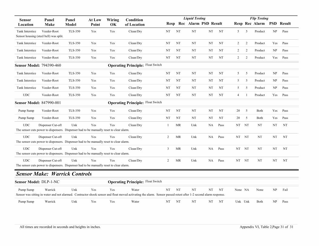
Sensor Location
Panel Make
Panel Model
At Low Point
Wiring OK
Condition of Location Resp Rec Alarm PSD Result Resp Rec PSD ResultAlarm
Liquid Testing Flip Testing
Tank Interstice Veeder-Root TLS-350 Yes Yes Clean/Dry NT NT NT NT NT 5 5 NP PassProductSensor housing (steel bell) was split.
Tank Interstice Veeder-Root TLS-350 Yes Yes Clean/Dry NT NT NT NT NT 2 2 Yes PassProduct
Tank Interstice Veeder-Root TLS-350 Yes Yes Clean/Dry NT NT NT NT NT 2 2 NP PassProduct
Tank Interstice Veeder-Root TLS-350 Yes Yes Clean/Dry NT NT NT NT NT 2 2 Yes PassProduct
Sensor Model: 794390-460 Operating Principle: Float Switch
Tank Interstice Veeder-Root TLS-350 Yes Yes Clean/Dry NT NT NT NT NT 5 5 NP PassProduct
Tank Interstice Veeder-Root TLS-350 Yes Yes Clean/Dry NT NT NT NT NT 5 5 NP PassProduct
Tank Interstice Veeder-Root TLS-350 Yes Yes Clean/Dry NT NT NT NT NT 5 5 NP PassProduct
UDC Veeder-Root TLS-350 Yes Yes Clean/Dry NT NT NT NT NT 4 1 Yes PassProduct
Sensor Model: 847990-001 Operating Principle: Float Switch
Pump Sump Veeder-Root TLS-350 Yes Yes Clean/Dry NT NT NT NT NT 20 5 Yes PassBoth
Pump Sump Veeder-Root TLS-350 Yes Yes Clean/Dry NT NT NT NT NT 20 5 Yes PassBoth
UDC Dispenser Cut-off Unk Yes Yes Clean/Dry 1 MR Unk NA Pass NT NT NT NTNTThe sensor cuts power to dispensers. Dispenser had to be manually reset to clear alarm.
UDC Dispenser Cut-off Unk Yes Yes Clean/Dry 2 MR Unk NA Pass NT NT NT NTNTThe sensor cuts power to dispensers. Dispenser had to be manually reset to clear alarm.
UDC Dispenser Cut-off Unk Yes Yes Clean/Dry 3 MR Unk NA Pass NT NT NT NTNTThe sensor cuts power to dispensers. Dispenser had to be manually reset to clear alarm.
UDC Dispenser Cut-off Unk Yes Yes Clean/Dry 2 MR Unk NA Pass NT NT NT NTNTThe sensor cuts power to dispensers. Dispenser had to be manually reset to clear alarm.
Sensor Make: Warrick ControlsSensor Model: DLP-1-NC Operating Principle: Float Switch
Pump Sump Warrick Unk Yes Yes Water NT NT NT NT NT None NA NP FailNoneSensor was sitting in water and not alarmed. Contractor shook sensor and float moved activating the alarm. Sensor passed retest after 1-2 second alarm response.
Pump Sump Warrick Unk Yes Yes Water NT NT NT NT NT Unk Unk NP PassBoth
Page 31 of 31All times are recorded in seconds and heights in inches. Appendix VI, Table 2,

APPENDIX VI, TABLE 3Field Data for Discriminating Sensors
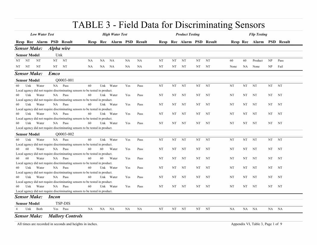
TABLE 3 - Field Data for Discriminating SensorsResp Rec Alarm PSD Result Resp Rec Alarm PSD Result Resp Rec Alarm PSD Result Resp Rec Alarm PSD Result
Low Water Test High Water Test Product Testing Flip Testing
Sensor Make: Alpha wireSensor Model UnkNT NT NT NT NT NA NA NA NA NA NT NT NT NT NT 60 60 Product NP Pass
NT NT NT NT NT NA NA NA NA NA NT NT NT NT NT None NA None NP Fail
Sensor Make: EmcoSensor Model Q0003-00160 Unk Water NA Pass 60 Unk Water Yes Pass NT NT NT NT NT NT NT NT NT NTLocal agency did not require discriminating sensors to be tested in product.60 Unk Water NA Pass 60 Unk Water Yes Pass NT NT NT NT NT NT NT NT NT NTLocal agency did not require discriminating sensors to be tested in product.60 Unk Water NA Pass 60 Unk Water Yes Pass NT NT NT NT NT NT NT NT NT NTLocal agency did not require discriminating sensors to be tested in product.60 Unk Water NA Pass 60 Unk Water Yes Pass NT NT NT NT NT NT NT NT NT NTLocal agency did not require discriminating sensors to be tested in product.60 Unk Water NA Pass 60 Unk Water Yes Pass NT NT NT NT NT NT NT NT NT NTLocal agency did not require discriminating sensors to be tested in product.
Sensor Model Q0003-00260 Unk Water NA Pass 60 Unk Water Yes Pass NT NT NT NT NT NT NT NT NT NTLocal agency did not require discriminating sensors to be tested in product.60 60 Water NA Pass 60 60 Water Yes Pass NT NT NT NT NT NT NT NT NT NTLocal agency did not require discriminating sensors to be tested in product.60 60 Water NA Pass 60 60 Water Yes Pass NT NT NT NT NT NT NT NT NT NTLocal agency did not require discriminating sensors to be tested in product.60 Unk Water NA Pass 60 Unk Water Yes Pass NT NT NT NT NT NT NT NT NT NTLocal agency did not require discriminating sensors to be tested in product.60 Unk Water NA Pass 60 Unk Water Yes Pass NT NT NT NT NT NT NT NT NT NTLocal agency did not require discriminating sensors to be tested in product.60 Unk Water NA Pass 60 Unk Water Yes Pass NT NT NT NT NT NT NT NT NT NTLocal agency did not require discriminating sensors to be tested in product.
Sensor Make: InconSensor Model TSP-DIS4 Unk Both Yes Pass NA NA NA NA NA NT NT NT NT NT NA NA NA NA NA
Sensor Make: Mallory ControlsPage 1 of 9All times are recorded in seconds and heights in inches. Appendix VI, Table 3,

Resp Rec Alarm PSD Result Resp Rec Alarm PSD Result Resp Rec Alarm PSD Result Resp Rec Alarm PSD Result
Low Water Test High Water Test Product Testing Flip Testing
Sensor Model Pollulert FD 221GTRA10 Dry Water NA Pass NA NA NA NA NA 10 Dry Product NA Pass NA NA NA NA NASensor had to be wiped dry to come out of alarm.10 Dry Water NA Pass NA NA NA NA NA 10 Dry Product NA Pass NA NA NA NA NASensor had to be wiped dry to come out of alarm.10 Dry Water NA Pass NA NA NA NA NA 10 Dry Product NA Pass NA NA NA NA NASensor had to be wiped dry to come out of alarm.
Sensor Model Pollulert MD 241RRA10 Dry Water NA Pass NA NA NA NA NA 10 Dry Product NA Pass NA NA NA NA NASensor had to be wiped dry to come out of alarm.10 Dry Water NA Pass NA NA NA NA NA 10 Dry Product NA Pass NA NA NA NA NASensor had to be wiped dry to come out of alarm.10 Dry Water NA Pass NA NA NA NA NA 10 Dry Product NA Pass NA NA NA NA NASensor had to be wiped dry to come out of alarm.NT NT NT NT NT NA NA NA NA NA 10 10 Product Yes Pass NA NA NA NA NA
NT NT NT NT NT NA NA NA NA NA NA NA None No Fail NA NA NA NA NASensor failed the test, but the company is out of business.So, owner might have to change the system. Inspector gave the owner two weeks to fix it or replace It.NT NT NT NT NT NA NA NA NA NA 20 10 Product Yes Pass NA NA NA NA NA
Sensor Make: Red JacketSensor Model RE400-2031 1 Water NA Pass NA NA NA NA NA NT NT NT NT NT NA NA NA NA NA
1 1 Water NA Pass NA NA NA NA NA NT NT NT NT NT NA NA NA NA NA
1 1 Water NA Pass NA NA NA NA NA NT NT NT NT NT NA NA NA NA NA
1 1 Water NA Pass NA NA NA NA NA NT NT NT NT NT NA NA NA NA NA
1 1 Water NA Pass NA NA NA NA NA NT NT NT NT NT NA NA NA NA NA
1 1 Water NA Pass NA NA NA NA NA NT NT NT NT NT NA NA NA NA NA
Sensor Make: Veeder-RootSensor Model 794380-320Unk Unk Unk Unk Unk 2 5 Water Unk Pass 383 1030 Product Unk Pass NA NA NA NA NA
Unk Unk Unk Unk Unk 1 7 Water Unk Pass 395 962 Product Unk Pass NA NA NA NA NA
Sensor Model 794380-3225 Unk Water NA Pass 5 5 Water Yes Pass NT NT NT NT NT NT NT NT NT NTTechnician flipped the sensor, activating both low and high water alarms at the same time.
Page 2 of 9All times are recorded in seconds and heights in inches. Appendix VI, Table 3,

Resp Rec Alarm PSD Result Resp Rec Alarm PSD Result Resp Rec Alarm PSD Result Resp Rec Alarm PSD Result
Low Water Test High Water Test Product Testing Flip Testing
Sensor Model 794380-341NT NT NT NT NT 5 1 Water Yes Pass 5 1 Product Yes Pass NA NA NA NA NAWhen placed in fuel, alarms went off as water - pump shut-down worked; waste oil sensor failed, replaced and recorded on separate sheet.10 10 Water Yes Pass NA NA NA NA NA 10 10 Water Yes Fail NA NA NA NA NATechnician had to clean the sensor with a rag completely (especially in the small window at sensor's center) before fuel could be detected. After cleaning sensor did detect fuel.10 10 Water Yes Pass NA NA NA NA NA 10 10 Water Yes Fail NA NA NA NA NATechnician had to clean the sensor with a rag completely (especially in the small window at sensor's center) before fuel could be detected. After cleaning sensor did detect fuel.10 10 Water Yes Pass NA NA NA NA NA 10 10 Water Yes Fail NA NA NA NA NATechnician had to clean the sensor with a rag completely (especially in the small window at sensor's center) before fuel could be detected. After cleaning sensor did detect fuel.Unk Unk Unk Unk Unk NA NA NA NA NA NA NA None Unk Fail NA NA NA NA NA
Unk Unk Unk Unk Unk NA NA NA NA NA 2 2 Product Unk Pass NA NA NA NA NA
Unk Unk Unk Unk Unk NA NA NA NA NA 2570 4240 Product Unk Pass NA NA NA NA NA
Unk Unk Unk Unk Unk NA NA NA NA NA 5 5 Product Unk Pass NA NA NA NA NA
3 3 Water Yes Pass NA NA NA NA NA 3 3 Product Yes Pass NA NA NA NA NA
12 1 Water NA Pass NA 0 NA NA NA 13 Unk Water No Fail NA NA NA NA NASensor sets water alarm for product test. After testing the sensor was replaced and the new sensor was setting the right alarm.NT NT NT NT NT 5 1 Water Yes Pass 5 1 Product Yes Pass NA NA NA NA NA
NT NT NT NT NT 5 1 Water Yes Pass 5 1 Product Yes Pass NA NA NA NA NA
NT NT NT NT NT NA NA NA NA NA Unk Unk None No Fail NA NA NA NA NAReplaced with same type of sensor.3 2 Both Yes Pass NA NA NA NA NA 3 2 Both Yes Pass NA NA NA NA NASensor had been programmed to give the same alarm in water and product.3 2 Both Yes Pass NA NA NA NA NA 3 2 Both Yes Pass NA NA NA NA NASensor had been programmed to give the same alarm in water and product.3 2 Both Yes Pass NA NA NA NA NA 3 2 Both Yes Pass NA NA NA NA NASensor had been programmed to give the same alarm in water and product.3 3 Water Yes Pass NA NA NA NA NA 3 3 Water Yes Fail NA NA NA NA NADetected product as water. Since pump shuts down for product or water, Local Agency did not require sensor to be changed. Owner will replace sensor or re-program as non-discriminating.12 1 Water NA Pass NA 0 NA NA NA 13 Unk Product Yes Pass NA NA NA NA NA
Unk Unk Unk Unk Unk NA NA NA NA NA 2 2 Product Unk Pass NA NA NA NA NA
12 1 Water NA Pass NA 0 NA NA NA 12 Unk Water No Fail NA NA NA NA NASensor sets water alarm for product test. After testing, sensor was replaced and the new sensor was setting the right alarm.NT NT NT NT NT NA 0 NA NA NA 13 Unk Water NA Fail NA NA NA NA NASensor was tested with both unleaded gasoline and waste oil. Both cases, water alarms were observed. Sensor was not approved for use in waste oil. After testing, sensor was replaced and it passed the product test.Unk Unk Unk Unk Unk NA NA NA NA NA NA NA None Unk Fail NA NA NA NA NA
Unk Unk Unk Unk Unk 3 10 Water Unk Pass 358 2450 Product Unk Pass NA NA NA NA NA
Page 3 of 9All times are recorded in seconds and heights in inches. Appendix VI, Table 3,

Resp Rec Alarm PSD Result Resp Rec Alarm PSD Result Resp Rec Alarm PSD Result Resp Rec Alarm PSD Result
Low Water Test High Water Test Product Testing Flip Testing
Unk Unk Unk Unk Unk NA NA NA NA NA 4 10 Product Unk Pass NA NA NA NA NA
Unk Unk Unk Unk Unk NA NA NA NA NA 417 1055 Product Unk Pass NA NA NA NA NA
3 3 Water Yes Pass NA NA NA NA NA 3 3 Water Yes Fail NA NA NA NA NADetected product as water. Since pump shuts down for product or water, Local Agency did not require sensor to be changed. Owner will replace sensor or reprogram as non-discriminating.
Sensor Model 794380-3505 5 Water NA Pass 5 5 Water Yes Pass 360 465 Product Yes Pass NA NA NA NA NATechnician left sensor in product for 2min & 45sec. He rinsed the sensor with soapy water after alarm activated to speed up recovery time.1 1 Water NA Pass 5 5 Water Yes Pass 360 765 Product Yes Pass NA NA NA NA NATechnician left sensor in product for 2min & 45sec. He rinsed the sensor with soapy water after alarm activated to speed up recovery time.2 2 Water NA Pass 2 2 Water Yes Pass 300 480 Product Yes Pass NA NA NA NA NA
2 2 Water NA Pass 2 Unk Water Yes Pass 480 Non Product Yes Fail NA NA NA NA NASensor did not come out of alarm after being tested in product, so technician replaced it.2 2 Water NA Pass None Non None No Fail none Unk None No Fail NA NA NA NA NASensor did not respond during high water or product testing. Technician suspected wiring problem, since sensor was replaced but test results did not change.2 2 Water NA Pass 2 2 Water Yes Pass 180 NA Product Yes Pass NA NA NA NA NA
2 2 Water NA Pass 2 2 Water No Fail Unk Unk Product No Fail NA NA NA NA NATechnician suspected a problem with the wiring at this site.5 5 Water NA Pass 5 5 Water NA Pass 480 300 Product Yes Pass NA NA NA NA NATechnician left sensor in product for 2min & 45sec. He rinsed the sensor with soapy water after alarm activated to speed up recovery time.1 1 Water NA Pass 5 5 Water Yes Pass 330 600 Product Yes Pass NA NA NA NA NATechnician left sensor in product for 2min & 45sec. He rinsed the sensor with soapy water after alarm activated to speed up recovery time.5 Unk Water NA Pass 2 2 Water Yes Pass 300 600 Product Yes Pass NA NA NA NA NASensors were left in fuel for 3 minutes. They alarm 2-5 minutes after being pulled from fuel. This speeds up recovery time.5 5 Water NA Pass 5 5 Water Yes Pass 300 360 Product Yes Pass NA NA NA NA NATechnician left sensor in product for 2min & 45sec. He rinsed the sensor with soapy water after alarm activated to speed up recovery time.5 5 Water NA Pass 5 5 Water Yes Pass 330 420 Product Yes Pass NA NA NA NA NATechnician left sensor in product for 2min & 45sec. He rinsed the sensor with soapy water after alarm activated to speed up recovery time.5 5 Water NA Pass 5 5 Water NA Pass 300 540 Product Yes Pass NA NA NA NA NATechnician left sensor in product for 2min & 45sec. He rinsed the sensor with soapy water after alarm activated to speed up recovery time.5 5 Water NA Pass 5 5 Water NA Pass 720 360 Product Yes Pass NA NA NA NA NATechnician left sensor in product for 2min & 45sec. He rinsed the sensor with soapy water after alarm activated to speed up recovery time.5 5 Water NA Pass 5 5 Water NA Pass 360 1500 Product Yes Pass NA NA NA NA NATechnician left sensor in product for 2min & 45sec. He rinsed the sensor with soapy water after alarm activated to speed up recovery time.5 Unk Water NA Pass 2 2 Water Yes Pass 420 720 Product Yes Pass NA NA NA NA NASensors were left in fuel for 3 minutes. They alarm 2-5 minutes after being pulled from fuel. This speeds up recovery time.1 1 Water NA Pass 5 5 Water Yes Pass 300 540 Product Yes Pass NA NA NA NA NATechnician left sensor in product for 2min & 45sec. He rinsed the sensor with soapy water after alarm activated to speed up recovery time.
Page 4 of 9All times are recorded in seconds and heights in inches. Appendix VI, Table 3,

Resp Rec Alarm PSD Result Resp Rec Alarm PSD Result Resp Rec Alarm PSD Result Resp Rec Alarm PSD Result
Low Water Test High Water Test Product Testing Flip Testing
7 1 Water NA Pass 3 1 Water Yes Pass 360 720 Product Yes Pass NA NA NA NA NAFor product test, sensor was left in fuel for 3 minutes.NT NT NT NT NT 5 1 Water Yes Pass 360 900 Product Yes Pass NA NA NA NA NA
NT NT NT NT NT 5 1 Water Yes Pass 360 900 Product Yes Pass NA NA NA NA NA
NT NT NT NT NT 5 1 Water Yes Pass 360 900 Product Yes Pass NA NA NA NA NA
NT NT NT NT NT 5 1 Water Yes Pass 840 Unk Product Yes Pass NA NA NA NA NATakes longer for this sensor to alarm because often left sitting in water.7 1 Water NA Pass 5 1 Water Yes Pass 300 300 Product Yes Pass NA NA NA NA NAFor product test, sensor was left in fuel for 3 minutes.7 1 Water NA Pass 4 1 Water Yes Pass 360 590 Product Yes Pass NA NA NA NA NAFor product test, sensor was left in fuel for 3 minutes.7 1 Water NA Pass 5 1 Water Yes Pass 360 660 Product Yes Pass NA NA NA NA NAFor product test, sensor was left in fuel for 3 minutes.Unk Unk Unk Unk Unk 4 5 Water Unk Pass 238 3531 Product Unk Pass NA NA NA NA NA
7 1 Water NA Pass 6 1 Water Yes Pass 360 1020 Product Yes Pass NA NA NA NA NAFor product test, sensor was left in fuel for 3 minutes.5 Unk Water NA Pass 2 2 Water Yes Pass 300 600 Product Yes Pass NA NA NA NA NASensors were left in fuel for 3 minutes. They alarm 2-5 minutes after being pulled from fuel. This speeds up recovery time.Unk Unk Unk Unk Unk 2 10 Water Unk Pass 365 1100 Product Unk Pass NA NA NA NA NA
Unk Unk Unk Unk Unk 4 7 Water Unk Pass 357 890 Product Unk Pass NA NA NA NA NA
2 2 Water NA Pass 2 2 Water No Fail Unk Unk Product No Fail NA NA NA NA NASensor alarmed, but failed PSD. Problem with the relay is suspected.Unk Unk Unk Unk Unk 3 9 Water Unk Pass 206 1390 Product Unk Pass NA NA NA NA NA
5 Unk Water NA Pass 2 2 Water Yes Pass 300 600 Product Yes Pass NA NA NA NA NASensors were left in fuel for 3 minutes. They alarm 2-5 minutes after being pulled from fuel. This speeds up recovery time.5 5 Water NA Pass 5 5 Water NA Pass 420 420 Product Yes Pass NA NA NA NA NATechnician left sensor in product for 2min & 45sec. He rinsed the sensor with soapy water after alarm activated to speed up recovery time.Unk Unk Unk Unk Unk 5 10 Water Unk Pass 318 1189 Product Unk Pass NA NA NA NA NA
5 Unk Water NA Pass 2 2 Water Yes Pass 420 720 Product Yes Pass NA NA NA NA NASensors were left in fuel for 3 minutes. They alarm 2-5 minutes after being pulled from fuel. This speeds up recovery time.7 1 Water NA Pass 6 1 Water Yes Pass 300 483 Product Yes Pass NA NA NA NA NAFor product test, sensor was left in fuel for 3 minutes.Unk Unk Unk Unk Unk 4 9 Water Unk Pass 3009 6120 Product Unk Pass NA NA NA NA NA
5 Unk Water NA Pass 2 2 Water Yes Pass 300 600 Product Yes Pass NA NA NA NA NASensors were left in fuel for 3 minutes. They alarm 2-5 minutes after being pulled from fuel. This speeds up recovery time.
Sensor Model 794380-3523 1 Both Yes Pass 3 1 Both Yes Pass NT NT NT NT NT NT NT NT NT NT
Page 5 of 9All times are recorded in seconds and heights in inches. Appendix VI, Table 3,

Resp Rec Alarm PSD Result Resp Rec Alarm PSD Result Resp Rec Alarm PSD Result Resp Rec Alarm PSD Result
Low Water Test High Water Test Product Testing Flip Testing
6 1 Both Yes Pass NT NT NT NT NT NT NT NT NT NT NT NT NT NT NTSensors were tested as a non-discriminating float sensor.6 1 Both Yes Pass NT NT NT NT NT NT NT NT NT NT NT NT NT NT NTSensors were tested as a non-discriminating float sensor.NT NT NT NT NT 5 1 Both Yes Pass NT NT NT NT NT NT NT NT NT NTThese sensors were located in the fill sump, in the overfill bucket.NT NT NT NT NT 1 1 Both Yes Pass NT NT NT NT NT NT NT NT NT NTThese sensors were located in the fill sump, in the overfill bucket.NT NT NT NT NT 5 1 Both Yes Pass NT NT NT NT NT NT NT NT NT NTThese sensors were located in the fill sump, in the overfill bucket.3 1 Both Yes Pass 3 1 Both Yes Pass NT NT NT NT NT NT NT NT NT NT
10 5 Water NA Pass 10 5 Water Yes Pass NT NT NT NT NT NT NT NT NT NTFlip test activated both low and high liquid alarms. Technician did not test the sensor in product.10 5 Water NA Pass 10 5 Water Yes Pass NT NT NT NT NT NT NT NT NT NTFlip test activated both low and high liquid alarms. Technician did not test the sensor in product.10 5 Water NA Pass 10 5 Water Yes Pass NT NT NT NT NT NT NT NT NT NTFlip test activated both low and high liquid alarms. Technician did not test the sensor in product.15 5 Water NA Pass 15 5 Water Yes Pass NT NT NT NT NT NT NT NT NT NTFlip test activated both low and high liquid alarms. Technician did not test the sensor in product. Water in sump was not high enough to activate the alarm.5 Unk Water NA Pass 5 Unk Water Unk Pass NT NT NT NT NT NT NT NT NT NTLocal agency did not test discriminating sensors in product. Both low and high level alarms were activated by flipping the sensor.5 Unk Water NA Pass 5 Unk Water Unk Pass NT NT NT NT NT NT NT NT NT NTLocal agency did not test discriminating sensors in product. Both low and high level alarms were activated by flipping the sensor.Unk Unk None No Fail 3 1 Both Yes Pass NT NT NT NT NT NT NT NT NT NTSensor's low float did not activate (would not reset). Sensor was replaced by the owner without informing the local agnecy nor the contractor who does the routine inspection. Apparently, they did not retest sensor's functinality.Unk Unk Unk Unk Unk 10 17 Water Unk Pass 425 2435 Product Unk Pass NT NT NT NT NTCleaned in Coleman Fuel.Unk Unk Unk Unk Unk 8 16 Water Unk Pass 446 1548 Product Unk Pass NT NT NT NT NT
Unk Unk Unk Unk Unk 12 18 Water Unk Pass 468 960 Product Unk Pass NT NT NT NT NT
Unk Unk Unk Unk Unk 4 10 Water Unk Pass 452 960 Product Unk Pass NT NT NT NT NT
Unk Unk Unk Unk Unk 6 11 Water Unk Pass NA NA Water Unk Fail NT NT NT NT NT
Unk Unk Unk Unk Unk NT NT NT NT NT 543 570 Product Unk Pass NT NT NT NT NT
Unk Unk Unk Unk Unk 10 18 Water Unk Pass 275 2595 Product Unk Pass NT NT NT NT NTCleaned in Coleman Fuel.6 1 Both Yes Pass NT NT NT NT NT NT NT NT NT NT NT NT NT NT NTSensors were tested as a non-discriminating float sensor.Unk Unk Unk Unk Unk 7 13 Water Unk Pass 425 1413 Product Unk Pass NT NT NT NT NT
Page 6 of 9All times are recorded in seconds and heights in inches. Appendix VI, Table 3,

Resp Rec Alarm PSD Result Resp Rec Alarm PSD Result Resp Rec Alarm PSD Result Resp Rec Alarm PSD Result
Low Water Test High Water Test Product Testing Flip Testing
Unk Unk Unk Unk Unk 6 16 Water Unk Pass 435 2040 Product Unk Pass NT NT NT NT NT
Unk Unk Unk Unk Unk 9 22 Water Unk Pass 530 2040 Product Unk Pass NT NT NT NT NTCleaned in Coleman Fuel.Unk Unk Unk Unk Unk 4 14 Water Unk Pass 355 1640 Product Unk Pass NT NT NT NT NTCleaned in Coleman Fuel.Unk Unk Unk Unk Unk 5 13 Water Unk Pass 414 1240 Product Unk Pass NT NT NT NT NT
Unk Unk Unk Unk Unk 5 12 Water Unk Pass 379 1143 Product Unk Pass NT NT NT NT NT
Unk Unk Unk Unk Unk 6 16 Water Unk Pass 429 1166 Product Unk Pass NT NT NT NT NT
Unk Unk Unk Unk Unk 8 21 Water Unk Pass 422 1320 Product Unk Pass NT NT NT NT NT
Unk Unk Unk Unk Unk 5 12 Water Unk Pass 425 1271 Product Unk Pass NT NT NT NT NT
Unk Unk Unk Unk Unk 4 9 Water Unk Pass 483 1229 Product Unk Pass NT NT NT NT NT
Unk Unk Unk Unk Unk 7 13 Water Unk Pass 299 573 Product Unk Pass NT NT NT NT NT
Unk Unk Unk Unk Unk 4 13 Water Unk Pass 318 481 Product Unk Pass NT NT NT NT NT
Unk Unk Unk Unk Unk 4 11 Water Unk Pass 397 690 Product Unk Pass NT NT NT NT NT
Unk Unk Unk Unk Unk 6 10 Water Unk Pass 489 1190 Product Unk Pass NT NT NT NT NT
Unk Unk Unk Unk Unk 5 11 Water Unk Pass 539 1631 Product Unk Pass NT NT NT NT NT
Unk Unk Unk Unk Unk 4 9 Water Unk Pass 474 1299 Product Unk Pass NT NT NT NT NT
Unk Unk Unk Unk Unk 9 15 Water Unk Pass 495 1256 Product Unk Pass NT NT NT NT NT
Unk Unk Unk Unk Unk 6 14 Water Unk Pass Unk 813 Product Unk Pass NT NT NT NT NT
Unk Unk Unk Unk Unk 6 16 Water Unk Pass 335 2010 Product Unk Pass NT NT NT NT NT
Unk Unk Unk Unk Unk 2 12 Water Unk Pass 470 1078 Product Unk Pass NT NT NT NT NT
Unk Unk Unk Unk Unk 4 11 Water Unk Pass 350 3499 Product Unk Pass NT NT NT NT NT
Unk Unk Unk Unk Unk 5 10 Water Unk Pass 459 1769 Product Unk Pass NT NT NT NT NT
Unk Unk Unk Unk Unk 6 14 Water Unk Pass 462 2206 Product Unk Pass NT NT NT NT NT
Unk Unk Unk Unk Unk 5 11 Water Unk Pass 453 930 Product Unk Pass NT NT NT NT NT
Unk Unk Unk Unk Unk 6 13 Water Unk Pass 440 1140 Product Unk Pass NT NT NT NT NT
Unk Unk Unk Unk Unk 8 19 Water Unk Pass 420 1851 Product Unk Pass NT NT NT NT NT
Unk Unk Unk Unk Unk 5 13 Water Unk Pass 540 1760 Product Unk Pass NT NT NT NT NT
Unk Unk Unk Unk Unk 9 11 Water Unk Pass 360 1500 Product Unk Pass NT NT NT NT NT
Unk Unk Unk Unk Unk 8 21 Water Unk Pass 354 1807 Product Unk Pass NT NT NT NT NT
NT NT NT NT NT 5 5 Water Yes Pass NT NT NT NT NT 5 5 Water Yes PassSensor was programmed for PSD on high-liquid only, not product. Technician re-programmed for PSD on low, high, and product.
Page 7 of 9All times are recorded in seconds and heights in inches. Appendix VI, Table 3,

Resp Rec Alarm PSD Result Resp Rec Alarm PSD Result Resp Rec Alarm PSD Result Resp Rec Alarm PSD Result
Low Water Test High Water Test Product Testing Flip Testing
NT NT NT NT NT 5 5 Water Yes Pass NT NT NT NT NT 3 5 Water Yes PassSensor was programmed for PSD on high-liquid only, not product. Technician re-programmed for PSD on low, high, and product.NT NT NT NT NT 5 5 Water Yes Pass NT NT NT NT NT 3 5 Water Yes PassSensor was programmed for PSD on high-liquid only, not product. Technician re-programmed for PSD on low, high, and product.NT NT NT NT NT 5 5 Water Yes Pass NT NT NT NT NT 5 5 Water Yes PassSensor was programmed for PSD on high-liquid only, not product. Technician re-programmed for PSD on low, high, and product.NT NT NT NT NT 5 5 Water Yes Pass NT NT NT NT NT 5 Unk Water NP Pass
10 2 Water NA Pass 2 2 Water Yes Pass 260 Unk Product Yes Pass NT NT NT NT NTProgrammed for "high vapor mode".NT NT NT NT NT 5 5 Water Yes Pass NT NT NT NT NT 5 Unk Water NP Pass
3 3 Water NA Pass 2 2 Water Yes Pass 240 Unk Product Yes Pass NT NT NT NT NTProgrammed for "high vapor mode". Sensor intermittently activated "sensor out" alarm when being moved. Technician suspected a short in wiring where cable attaches to sensor.Unk Unk Unk Unk Unk 5 14 Water Unk Pass 730 1276 Product Unk Pass NT NT NT NT NT
Unk Unk Unk Unk Unk 13 21 Water Unk Pass 480 600 Product Unk Pass NT NT NT NT NT
NT NT NT NT NT NT NT NT NT NT NT NT NT NT NT NT NT NT NT NTWiring malfunctioning.NT NT NT NT NT NT NT NT NT NT NT NT NT NT NT NT NT NT NT NTWiring malfunctioning.NT NT NT NT NT NT NT NT NT NT NT NT NT NT NT NT NT NT NT NT
NT NT NT NT NT 60 5 Water Yes Pass NT NT NT NT NT NT NT NT NT NT
NT NT NT NT NT NA NA NA NA NA NT NT NT NT NT NT NT NT NT NTHad 2 bad relays that had to be fixed.NT NT NT NT NT 10 5 Water Yes Pass NT NT NT NT NT 5 Unk Water NP Pass
Unk Unk Unk Unk Unk 10 24 Water Unk Pass 520 1769 Product Unk Pass NT NT NT NT NT
NT NT NT NT NT NT NT NT NT NT NT NT NT NT NT NT NT NT NT NTHad 2 bad relays that had to be fixed.Unk Unk Unk Unk Unk 13 24 Water Unk Pass 420 1978 Product Unk Pass NT NT NT NT NT
Unk Unk Unk Unk Unk 18 25 Water Unk Pass 385 1470 Product Unk Pass NT NT NT NT NT
Unk Unk Unk Unk Unk 12 25 Water Unk Pass 412 1920 Product Unk Pass NT NT NT NT NT
Unk Unk Unk Unk Unk 12 25 Water Unk Pass 400 1695 Product Unk Pass NT NT NT NT NT
Unk Unk Unk Unk Unk 15 28 Water Unk Pass 335 2281 Product Unk Pass NT NT NT NT NT
NT NT NT NT NT 5 5 Water Yes Pass NT NT NT NT NT 5 5 Water Yes PassSensor was programmed for PSD on high-liquid only, not product. Technician re-programmed for PSD on low, high, and product.Unk Unk Unk Unk Unk 16 30 Water Unk Pass Unk Unk Product Unk Pass NT NT NT NT NTEmergency shut-off activated during testing, so no data was available.Unk Unk Unk Unk Unk 8 19 Water Unk Pass 420 1625 Product Unk Pass NT NT NT NT NT
Page 8 of 9All times are recorded in seconds and heights in inches. Appendix VI, Table 3,

Resp Rec Alarm PSD Result Resp Rec Alarm PSD Result Resp Rec Alarm PSD Result Resp Rec Alarm PSD Result
Low Water Test High Water Test Product Testing Flip Testing
Unk Unk Unk Unk Unk 9 19 Water Unk Pass NA NA None Unk Fail NT NT NT NT NT
Unk Unk Unk Unk Unk 6 15 Water Unk Pass 600 2120 Product Unk Pass NT NT NT NT NT
Unk Unk Unk Unk Unk 10 18 Water Unk Pass 600 2120 Product Unk Pass NT NT NT NT NT
15 Unk Water NA Pass 5 Unk Water Yes Pass 300 Unk Product Yes Pass NT NT NT NT NT
15 Unk Water NA Pass 6 Unk Water Yes Pass 390 Unk Product Yes Pass NT NT NT NT NT
15 2 Water NA Pass 15 3 Water Yes Pass 270 Unk Product Yes Pass NT NT NT NT NT
2 2 Product Yes Pass 2 2 Product Yes Pass 3 Unk Product Yes Pass NT NT NT NT NTProgrammed for "high vapor mode". Sensor was saturated with product vapors, so any liquid moving low or high float registrered as a product alarm.Unk Unk Unk Unk Unk 16 41 Water Unk Pass 450 1559 Product Unk Pass NT NT NT NT NT
Page 9 of 9All times are recorded in seconds and heights in inches. Appendix VI, Table 3,

APPENDIX VIIDiscussion of Point Liquid and Polymer Strip Discriminating Sensors

Appendix VII, Discussion of Point Liquid and Polymer Strip Discriminating Sensors Page 1 of 1
Point Liquid and Polymer Strip Discriminating Sensors
Point liquid type sensors use solid state electronics, which measure a particular physical property orproperties of liquid that contacts the detection element. An example is capacitance change sensors, whereliquid contacting the detection element acts as the dielectric in a capacitor. Air (no liquid present atsensor), hydrocarbon-based liquids, and water each have distinctly different dielectric constants. Acapacitance change sensor can detect this and respond differently when dry, or when exposed to water orhydrocarbons. Different responses from the sensor are interpreted by the control panel, which activatesthe appropriate alarm.
Point liquid discriminating sensors are capable of responding only to liquids directly in contact with thedetection element. This means that product floating on water will produce a water alarm if only the wateris in contact with the detection element. The detection elements are usually quite small, meaning that itdoes not take a great deal of water to potentially mask a product release. Point liquid discriminatingsensors tend to be smaller than the polymer strip type, and contain no moving parts. These attributesallow them to be installed in a variety of orientations, and in tight spaces (such as a tank interstice) wherepolymer strip sensors would not fit. Response time for this type of sensor varies by manufacturer andmodel, but is generally quick (less than 1 minute).
In contrast to point liquid discriminating sensors, polymer strip sensors use two detection elementscombined in one housing to discriminate between product and water*. The first detection element is afloat switch or ultrasonic detector that will activate a “low liquid level” alarm when in contact with anyliquid. It is located near the bottom of the sensor, and generally has a quick response time (less than 1minute). The second detection element is a hydrocarbon-sensing cable or strip that will activate a“product” alarm when exposed to hydrocarbon-based product. It will not respond to water. The cable orstrip typically runs from the bottom to the top of the sensor, and response times vary betweenapproximately 5 minutes and 20 minutes in unleaded fuel (may be 12 hours or more in diesel fuel). It is only by combining the float or ultrasonic liquid-sensing element with the hydrocarbon-sensingelement (cable or strip) that the polymer strip type sensor is able to discriminate between product andwater. A liquid entering the area monitored by the sensor will first contact the lowest float or ultrasonicdetection element, activating a “low liquid level” alarm. This alarm alerts the UST operator that liquid ispresent in the monitored area. If the liquid present is gasoline, the hydrocarbon-sensing element willactivate a “product” alarm approximately 5 to 20 minutes later (may be 12 hours or more for diesel fuel).In this event, the UST operator knows that product is present in the area monitored by the sensor, not justwater.
Polymer strip discriminating sensors offer the benefit of being able to detect a layer of hydrocarbonfloating on water, as long as the water level is in contact with the hydrocarbon-sensing strip. This makesthem well suited for locations where water ingress is common. Many (but not all) of these sensors havean additional float or ultrasonic liquid-sensing element located at the top end of the hydrocarbon-sensingstrip. This element activates a “high liquid level” alarm, which indicates that the liquid level hasexceeded the height of the hydrocarbon-sensing strip. Once water has reached this level, subsequentproduct releases may float above and fail to contact the hydrocarbon-sensing strip, resulting in a misseddetection. Polymer strip type sensors are less likely to miss a layer of product on water than point liquiddiscriminating sensors, but it is still a possibility that UST operators and inspectors should be aware of.
* Examples of polymer strip discriminating sensors include Emco Electronics models Q0003-002 and -003, Inconmodels TSP-DDS and TSP-DTS, and Veeder-Root models 794380-320, -322, -350, and –352).