fidap tutorial 3: curtain coating - university of...
TRANSCRIPT

___________________________________________
FIDAP Tutorial 3: Curtain Coating
Introduction: The aim of this tutorial is to set up and solve a problem involvingcurtain coating. There are a number of different industrial processes for covering asubstrate with a thin layer of coating material such as the manufacturing of photographicfilm. Three of the common methods include curtain coating, slot coating and slidecoating. In curtain coating, the liquid freely falls over a distance before it is layered overa moving substrate. Two of the advantages of curtain coating is that even very irregularshaped substrates can be covered with a thin layer of liquid and coating can be achievedat very high speeds. The flow in curtain coating can generally be divided into threezones: sheet forming zone, curtain flow zone, and impingement zone (see Figure 3-1).The impingement zone generally is the most important to understand because itultimately controls the entire process. Of primary importance are the free surfacethickness and the heel formation. These depend on the physical properties and the ratioof the speed of the falling liquid to the speed of the moving substrate. Heel formation isimportant to minimize in order to avoid the formation of eddies. Eddies may trap bubblesand lead to uneven coating. They are also susceptible to flow instabilities. This tutorialdemonstrates how to model the impingement zone of the curtain coating application.
Figure 3-1: Curtain Coating
Sheet Forming
Curtain Flow Zone
Impingement Zone
Static Contact
Dynamic Contact
Moving substrate
Heel Formation

FIDAP Tutorial 3: Curtain Coating______________________________________________________________________________________
© Fluent Inc., April 11, 2001 3-2
Objective:• Solve a problem involving multiple free surfaces which arises in Curtain Coating
Applications.
Prerequisites: This tutorial assumes that you have already completed FIDAPTutorial 1: Laminar Flow in a 2-D Mixing Elbow.
For a review of Free Surface Simulations in FIDAP, refer to• FIDAP Tutorial Manual: Chapter 6,• FIDAP Theory Manual: Chapter 9,• Introductory FIDAP Lecture Notes: Lecture 7
A one day Advanced Course in Free Surface Simulations is also available. Dates areavailable at www.fluent.com.
Files Needed for Tutorial 3:These files can be downloaded from www.fluent.users.com/fidap8/training• ccoat.FIPREP (Note: This file was modified by removing the "/" preceding the
commands for DENSITY and VISCOSITY. This step will be unnecessary to doin .FIPREP files created by GAMBIT versions 2.x and later.)
• ccoat.FDNEUT

FIDAP Tutorial 3: Curtain Coating______________________________________________________________________________________
© Fluent Inc., April 11, 2001 3-3
Problem Description: An approximation to the final free surface shape is shownschematically below in Figure 3-2. Cgs units are used and the units of length are given incm. The curtain thickness is .06 cm and falls from .48 cm above the moving substrate.In this example the speed of the falling liquid curtain at the "inlet" and the movingsubstrate "slip" are equal. Conservation of mass requires that the flow rate at the "inlet"and "outlet" match. A plug flow velocity profile (UY=-200 cm/s) is prescribed at the"inlet". There are two free surfaces. The left free surface is "lfree" and results in adynamic contact line. Typically high stresses develop near the dynamic contact pointcausing numerical oscillations which prevent convergence. A work around is to use theNavier slip condition for a few of the nodes on the solid boundary nearest the dynamiccontact line. For this purpose the solid boundary needs to have the entity type SLIP. Forgreater control of the mesh, the domain is divided into two faces (separated by the dashedline in the figure below) and the corresponding two edges which comprise the right freesurface are "rfree1" and "rfree2". In this case, we first compute the Reynolds numberwhich is a ratio of inertial and viscous forces. At the "outlet" the Reynolds number (Re=1.25 * 200 * .06/5.27) is 2.85 which puts the flow in the laminar regime.
Figure 3-2: Mesh Plot
"inlet" (UX=0, UY = -200)
"outlet" (UY=0)
"slip" (UT = 200, UN=0)
"lfree"
"rfree1"
"rfree2"
.06
.48
.489dynamic contact point
.06
ρ = 1.25 g/cm3
µ = 5.27 g/cm-sγ = 30 g/s2
L = .06 cmU = 200 cm/s
Reynolds number = 2.85Capillary number = 35.13

FIDAP Tutorial 3: Curtain Coating______________________________________________________________________________________
© Fluent Inc., April 11, 2001 3-4
STEP 1: Start up FIDAP
Start up FIDAP in the GUI mode using the identifier: ccoat
fidap –id ccoat –gui
STEP 2: Read in the .FIPREP file
1) The commands for the preliminary problem description have been created by themesh generator (GAMBIT) and are contained in the file ccoat.FIPREP (seeAppendix A). You will save a few steps by reading in this file. Select theREADFILE option on the FIDAP Command Toolbar near the top center of theFIDAP screen (Do NOT click FIPREP on the Main Module Toolbar). TheREADFILE Command form is shown below.
2) Click FILE on the READFILE Command form. The Select Read File Formappears. Highlight the file: ccoat.FIPREP and click ACCEPT at the bottom of theSelect Read File form. Click ACCEPT at the bottom of the READFILE
Main Module ToolbarFIDAP Command Toolbar

FIDAP Tutorial 3: Curtain Coating______________________________________________________________________________________
© Fluent Inc., April 11, 2001 3-5
Command Form. After successfully processing this file, the following messagewill appear in the Command History Window:
*****FISOLV INPUT DATA SUCCESSFULLY CREATED
STEP 3: Enter the FI-BC module
1) Click FI-BC on the Main Module Toolbar. The entity names (defined inGAMBIT) and group numbers are displayed in the graphics window. Forexample, the entity "inlet" is also Group 3 (G3) and it is located near the top leftof the graphics window. There are two distinct free surfaces. The left freesurface is "lfree". The right free surface is composed to two different entities:"rfree1" and "rfree2". The fluid enters at "inlet" (top) and exits at "outlet" (right).The horizontal edge is "slip". The continuum entity is "fluid".
The FI-BC Command Toolbar is shown below.
2) Click Set Display on the FI-BC menu toolbar. The SET DISPLAY OPTIONSCommand Form is shown below.

FIDAP Tutorial 3: Curtain Coating______________________________________________________________________________________
© Fluent Inc., April 11, 2001 3-6
3) Notice that the form is divided into three sections: ENTITY, GROUP and NODE.Click off Disp Label in section 1: ENTITY. Click off GROUP. The updated SETDISPLAY OPTIONS Command Form is shown below.

FIDAP Tutorial 3: Curtain Coating______________________________________________________________________________________
© Fluent Inc., April 11, 2001 3-7
4) Click CLEAR at the bottom of the SET DISPLAY OPTIONS Command form.The edges and vertex node numbers are displayed in the graphics window. Thecorner node numbers are 1, 2, 27, 28 and 14. These node numbers will be used inStep 15 #11 - #12 in order to define a physically correct normal at these cornerpoints. If you created your own mesh, the node numbers will most likely differfrom the ones shown below.

FIDAP Tutorial 3: Curtain Coating______________________________________________________________________________________
© Fluent Inc., April 11, 2001 3-8
5) It is also necessary to free the horizontal velocity component of the 3 closestnodes to node 14 that lie on the entity "slip". This step allows the user todetermine those node numbers. Click off ENTITY. Click ALL in section 3:NODE. The updated form is shown below.
6) Click CLEAR at the bottom of the form. All of the node numbers are displayed.

FIDAP Tutorial 3: Curtain Coating______________________________________________________________________________________
© Fluent Inc., April 11, 2001 3-9
Zoom into the region next to node 14 by moving the cursor to the region justbelow and to the left of node 14. Press the C key, depress the left mouse buttonand drag a small rectangle around the 3 nodes just to the right of node 14.Release the left mouse button.
7) The 3 nodes just to the right of node 14 are now easily visible as shown below.They are node numbers: 156, 136 and 155.
8) Click END on the FIDAP toolbar to end out of the FI-BC module.
Node 14

FIDAP Tutorial 3: Curtain Coating______________________________________________________________________________________
© Fluent Inc., April 11, 2001 3-10
STEP 4: Enter the FIPREP module
Click FIPREP on the Main Module Toolbar. The FIPREP Command Toolbar isshown below.
At this stage, the only information in the FIDAP database has been provided byGAMBIT from the .FIPREP file (see APPENDIX A). The .FIPREP file created byGAMBIT assumes certain basic commands and they may or may not beappropriate. In this example, the problem statement assumes that no freesurfaces are present and the physical properties (density and viscosity) are bothequal to one. Clearly, these two commands need to be changed. Table 3-1describes which FIDAP commands need to be modified.
Table 3-1: Commands that need to be Modified
Command Current FIDAPdatabase
FIDAP commands which needmodification
1. PROBLEM 2-D, LAMINAR,ISOTHERMAL,NONLINEAR, FIXED
Change FIXED to FREE
2. DENSITY CONSTANT = 1 CONSTANT = 1.25
3. VISCOSITY CONSTANT = 1 CONSTANT = 5.27
4. ENTITY Only NAME and TYPEfor boundary entities
SURFACE types need information onfree surface movement.SLIP type needs PROPERTY set.
In the .FIPREP file there are NO commands for the solver type, pressurealgorithm, boundary or initial conditions. IF NONE ARE ADDED BY THEUSER, FIDAP WILL USE THE DEFAULT VALUES WHICH MAY OR MAYNOT BE APPROPRIATE. Table 3-2 describes which FIDAP commands need tobe added.

FIDAP Tutorial 3: Curtain Coating______________________________________________________________________________________
© Fluent Inc., April 11, 2001 3-11
Table 3-2: Commands that need to be Added
No Command Current FIDAPdatabase (containsFIDAP default)
FIDAP commandsneeding to be added
1. Surface Tension SURFACETENSION = 0 SURFACETENSION = 30
2. Solver S.S. = 10 SEGREGATED
3. Pressure Penalty(when solver is S.S.)
MIXED andDISCONTINUOS
4. BoundaryConditions Zero normal stress Boundary conditions needed
5. Initial Conditions All D.O.F. = Zero UY = -200
6. Scale Value = 1 Value = .06
7. Relaxation No relaxation: ACCF = 0(when solver is S.S.)
Hybrid with user definedvalues
It is important to note that the defaults for pressure and relaxation are differentfor the S.S. and the SEGREGATED solver. Table 3-2 lists the default for the S.S.solver: Penalty method for pressure and No relaxation. If the solver is changedto SEGREGATED, the defaults change: Mixed Discontinuous for pressure andHybrid Relaxation.

FIDAP Tutorial 3: Curtain Coating______________________________________________________________________________________
© Fluent Inc., April 11, 2001 3-12
STEP 5: Define the PROBLEM Command
1) Click Simulation on the FIPREP Toolbar. The SIMULATION Toolbar is shownbelow.
Of the SIMULATION commands listed above, the following four commands willeither need to be modified (if they already exist in the FIDAP database) or theywill need to be added ( if they do not exist in the FIDAP database):a) PROBLEM (modify by changing fixed to free),b) SOLUTION (add the segregated solver instead of using the default S.S.
solver),c) PRESSURE (add: optional step since by changing the solver from S.S. to
SEGREGATED, FIDAP will automatically change the default PRESSUREformulation to MIXED DISCONTINUOUS)
d) RELAXATION (add and specify relaxation values for all degrees of freedom)

FIDAP Tutorial 3: Curtain Coating______________________________________________________________________________________
© Fluent Inc., April 11, 2001 3-13
2) Click PROBLEM on the Simulation Toolbar. The PROBLEM Command Formis shown below.
Note that not all of these options agree with those given in Table 3-1. The GUIshows that the CONVECTIVE TERM is LINEAR. An additional step is requiredto update the GUI to show the contents of the current database.
3) Click SELECT at the bottom of the PROBLEM Command and chooseALLENTRIES. The updated PROBLEM Command is shown below.
The form now shows the CONVECTIVE TERM to be NONLINEAR. All ofthese options are consistent with those shown in Table 3-1.

FIDAP Tutorial 3: Curtain Coating______________________________________________________________________________________
© Fluent Inc., April 11, 2001 3-14
The SURFACE TYPE is not selected, which means that the default: FIXEDsimulation is active.
4) In the PROBLEM Command form, click SURFACE TYPE and right click the !which appears to the right of FIXED. Change the keyword to FREE. The updatedform is shown below:
5) Click REPLACE at the bottom of the PROBLEM Command Form. If you clickADD, there willl be two PROBLEM commands in the database. The lastPROBLEM command will overwrite the previous one. This is not incorrect, itmeans there will be extra lines in the .FIJOUR file.
6) Confirm the change was made correctly by checking the FIDAP CommandHistory Window.

FIDAP Tutorial 3: Curtain Coating______________________________________________________________________________________
© Fluent Inc., April 11, 2001 3-15
STEP 6: Define the Solver
The user must next decide on a solver. For free surface problems, there are two choices:the Newton Solvers and the Segregated Solvers A further consideration must also begiven to the type of free surface update which determines how the nodes on the freesurface are to move. The two choices are Kinematic and Normal. The kinematic updateis generally preferred for problems in which the Capillary number >1 and the Normalstress update is generally preferred when the Capillary number < 1. The Capillarynumber is a ratio of viscous and surface tension forces (viscosity * velocity / surfacetension = 5.27 * 200 / 30 ) and is given by 35.13. Table 3-3 shows which updates areavailable with each of the solvers.
Table 3-3: Choice of Free Surface Updates For Newton and Segregated Solver
Newton Solver Segregated Solver
Kinematic (Ca>1) Kinematic (Ca >1)
Normal Stress (Ca < 1)
For this problem, Ca >1 and therefore, the Kinematic approach is preferred. If theproblem was a large 2-D problem or a 3-D problem we would be forced to use theSegregated Solver because of its lower memory requirement. However, this is arelatively small 2-D problem, so that either solver could be used.
Another choice that needs to be made is the Remeshing Scheme which determines howthe nodes below the free surface move. There are three remeshing choices: Spines,Mapped and Elastic. Even though the remeshing scheme is not specified until Step 14, itis important to consider it in this step because not all the remeshing schemes areavailable with both solvers. A general recommendation to use the Spines approach forproblems in which the mesh deformation is not large, otherwise either the Mapped orElastic approach is needed. Table 3-4 shows which remeshing schemes are availablewith either solver.

FIDAP Tutorial 3: Curtain Coating______________________________________________________________________________________
© Fluent Inc., April 11, 2001 3-16
Table 3-4: Choice of Remeshing Schemes for Newton and Segregated Solver
Newton Solver Segregated Solver
Spines (small mesh deformation) Spines (small mesh deformation)
Mapped (moderate mesh deformation)
Elastic (very large deformation)
For this problem the mesh is expected to deform moderately, therefore the choice is themapped scheme which is only available with the segregated solver.
Thus, using the Capillary number and estimation of mesh deformation, the choices are:the segregated solver and the mapped option for the free surface update.
The solver and free surface update are chosen in the SOLUTION command.
1) Click SOLUTION on the SIMULATION Command Form. The SOLUTIONCommand Form is shown below.

FIDAP Tutorial 3: Curtain Coating______________________________________________________________________________________
© Fluent Inc., April 11, 2001 3-17
2) Right click on the ! to the right of S.S. and choose SEGREGATED. Change thevalue of the keyword SEGREGATED from 10 to 100. Click SOLUTIONTOLERANCE and input the value .0001 (the default is .001) for the keywordVELCONV. Click FREE SURFACE ITER. and input a value of 500 for thekeyword KINEMATIC. Click FREE SURFACE CONV. TOL and input a valueof .001 (the default is .01) for the keyword SURFCONV. The updatedSOLUTION Command form is shown below.
3) Click ADD at the bottom of the SOLUTION Command form.
4) Check the Command History Window to confirm the change was made correctly.
STEP 7: Define the PRESSURE Formulation
1) Click PRESSURE on the SIMULATION Command Form. The PRESSURECommand Form is shown below.

FIDAP Tutorial 3: Curtain Coating______________________________________________________________________________________
© Fluent Inc., April 11, 2001 3-18
2) Change the PRESSURE APPROXIMATION from PENALTY to MIXED. Theupdated PRESSURE Command form is shown below.
Note that there is no value given for the keyword MIXED, thus the default (1.e-6)will be used. This step is optional since the default pressure formulation is mixed,discontinuous whenever the segregated solver is used.
3) Click ADD at the bottom of the PRESSURE Command Form.
4) Check the Command History Window to confirm the change was made correctly.

FIDAP Tutorial 3: Curtain Coating______________________________________________________________________________________
© Fluent Inc., April 11, 2001 3-19
STEP 8: Define the Relaxation Values
1) Since the SEGREGATED SOLVER has been chosen, the default relaxationscheme is the HYBRID type. The default values for each degree of freedom aregiven in the FIPREP manual (.3 for velocity, .6 for pressure and .5 for freesurface). In this step, the user will input a higher relaxation value (.975) for freesurface. Click RELAXATION on the Simulation Toolbar. The RELAXATIONCommand Form is shown below.
2) Click RELAXATION APPROACH and choose the HYBRID option. Theupdated RELAXATION Command form is shown below.

FIDAP Tutorial 3: Curtain Coating______________________________________________________________________________________
© Fluent Inc., April 11, 2001 3-20
Click ADD at the bottom of the RELAXATION Command Form. The DATANEEDED button will appear at the top right of the GUI.
3) You need to enter relaxation values for each of the degrees of freedom in theorder:UX, UY, UZ P , T and Free Surface
Move the cursor to the lower left wheat colored box and click in the box (or pressthe F2 key). Input the following data and then hit the Enter key:.3 .3 0 .5 0 .975
The DATA NEEDED button will not disappear because FIDAP is expecting 22values. Because only 6 values were entered, the remaining relaxation values willbe given the default 0. Click on the DATA NEEDED button to make it disappear.
4) Check the Command History Window to confirm the change was made correctly.

FIDAP Tutorial 3: Curtain Coating______________________________________________________________________________________
© Fluent Inc., April 11, 2001 3-21
STEP 9: Define the Physical Properties
The stress-divergence form of the momentum equation and the three boundary conditionsare shown below. The user needs to input values for the properties: density (ρ), viscosity(µ) and surface tension (γ), otherwise the default value 1 is used.
In addition, the Navier Slip Condition is needed to alleviate the large local stresses nearthe dynamic contact point. The user needs to specify the slip coefficient a.
Click Properties on the FIPREP Command Toolbar. The PROPERTIES Toolbar is shownbelow.
0=⋅nu Hpn γσ 2a +−= γσ ∇⋅= tt
tuu ⋅−= )(1 s
t aσ
( )[ ]Tpt
uuuuu ∇+∇⋅∇+−∇=
∇⋅+ µ
∂∂ρ
Stress Divergence Form of Momentum Equation
Boundary Conditions
Kinematic Normal Stress Tangential Stress

FIDAP Tutorial 3: Curtain Coating______________________________________________________________________________________
© Fluent Inc., April 11, 2001 3-22
STEP 10: Define the DENSITY
1) Click DENSITY on the PROPERTIES Toolbar. The DENSITY Command Formis shown below.
2) Click SELECT at the bottom of the DENSITY Command Form and chooseALLENTRIES. The updated DENSITY Command form is shown below. It isimportant to note this requires that the DENSITY command in the .FIPREP file beuncommented. This is automatically done in GAMBIT versions 2.0 and later. Ifan earlier version of GAMBIT was used to create the geometry, the DENSITYcommand must be uncommented by the user. The same is true for the VISCOSITYcommand. This was done if you used the file provided with this tutorial (See thecomment at the bottom of page 2: Files Needed for Tutorial 3).

FIDAP Tutorial 3: Curtain Coating______________________________________________________________________________________
© Fluent Inc., April 11, 2001 3-23
3) Change the value of the keyword CONSTANT = 1 to CONSTANT = 1.25.The updated DENSITY Command is shown below.
4) Click REPLACE at the bottom of the DENSITY Command Form.
5) Check the Command History Window to confirm the change was made correctly.

FIDAP Tutorial 3: Curtain Coating______________________________________________________________________________________
© Fluent Inc., April 11, 2001 3-24
STEP 11: Define the VISCOSITY
1) Click VISCOSITY on the PROPERTIES Toolbar. The VISCOSITY CommandForm is shown below.
2) Click SELECT at the bottom of the VISCOSITY Command Form and chooseALLENTRIES. The updated VISCOSITY Command form is shown below.

FIDAP Tutorial 3: Curtain Coating______________________________________________________________________________________
© Fluent Inc., April 11, 2001 3-25
3) Change the value of the keyword CONSTANT = 1 to CONSTANT = 5.27.The updated VISCOSITY Command is shown below.
4) Click REPLACE at the bottom of the VISCOSITY Command Form.
5) Check the Command History Window to confirm the change was made correctly.

FIDAP Tutorial 3: Curtain Coating______________________________________________________________________________________
© Fluent Inc., April 11, 2001 3-26
STEP 12: Define the SURFACE TENSION
1) Click SURFACETENSION on the PROPERTIES Toolbar. TheSURFACETENSION Command Form is shown below.
2) Click SELECT at the bottom of the SURFACETENSION Command Form andchoose ALLENTRIES. Note the warning message in the FIDAP CommandHistory Window:
This warning error occurs because there are no SURFACETENSION Commandspresent in the current database.
3) Change the MODEL SET NUMBER from SET = 1 to SET = fluid. You do notneed to type in the quotes. Input a value of 30 for the keyword CONSTANT.The updated form is shown below.

FIDAP Tutorial 3: Curtain Coating______________________________________________________________________________________
© Fluent Inc., April 11, 2001 3-27
4) Click ADD at the bottom of the SURFACETENSION Command Form.
5) Check the FIDAP History Window to confirm the change was made correctly.
STEP 13: Define the SLIPCOEFFICIENT
1) Click SLIPCOEFFICIENT on the PROPERTIES Toolbar. TheSLIPCOEFFICIENT Command Form is shown below.

FIDAP Tutorial 3: Curtain Coating______________________________________________________________________________________
© Fluent Inc., April 11, 2001 3-28
2) Change the MODEL SET NUMBER: SET = 1 to SET = slip. Input a value of .01for the keyword CONSTANT. Click TANGENTIAL VELOCITY and input avalue of 200 for the keyword UT. The updated form is shown below.
3) Click ADD at the bottom of the SLIPCOEFFICIENT Command Form.
4) Check the FIDAP History Window to confirm the change was made correctly.

FIDAP Tutorial 3: Curtain Coating______________________________________________________________________________________
© Fluent Inc., April 11, 2001 3-29
STEP 14: Modify the ENTITY Commands
Several modifications need to be made to the ENTITY Commands for the SURFACE andSLIP types. The user needs to decide how the nodes on and below the SURFACEentities: "lfree", "rfree1" and "rfree2" are to move. The user also needs to determine theSlip Coefficient for the entity "slip".
It has already been decided that the remeshing scheme is the mapped option, which isdetermined on the ENTITY command under the option SPINE GENERATION.
The user additionally needs to decide• how many nodes below the free surface are allowed to move• how the nodes on the free surface are to move• the contact angle at the end points of all SURFACE entity types if the endpoints
are not fixed (UX=UY=0).
Specifying the DEPTH keyword determines how many nodes are allowed to move. Thevalue is either
• 0 (maximum depth)• -1 (no spines are created)• positive number (specifies the depth including the node on the free surface).
For the mapped approach the choices for determining how the nodes on the free surfacemove are
• NORMAL (default)• PREFERRED
If the PREFERRED option is chosen the direction is specified by the values of thekeywords PREFERRED DIRECTION -X, -Y and -Z.
The contact angle is chosen by specifying the angle the outward tangent of the freesurface makes with the positive x- axis. It is only needed for nodes 14 and 27. (All ofthe other endpoints: nodes 1, 2, 28 are fixed. (Refer to the diagram shown in Step 3 #4for the node numbers). For 2-D problems there are two options for specifying thecontact angle.
• Use the ANG1 or ANG2 keyword on the ENTITY command.• Use the BCNODE command, specify the DEGREE OF FREEDOM to be
CONTACTANGLE and specify the NODE NUMBER at which the contact angle isbeing prescribed.
In this tutorial we will use the first option to specify the contact angle at node 27 (Step 14#8) and the second option to specify the contact angle at node 14 (Step 15, #15). Anadvantage of using the first option is that since the node number is not required, it wouldbe the preferred choice if the geometry needs to be remeshed (which would change thenode numbering). A summary of the correct modifications to the entity commands isgiven in Table 3-5.
FIDAP Tutorial 3: Curtain Coating______________________________________________________________________________________
© Fluent Inc., April 11, 2001 3-30
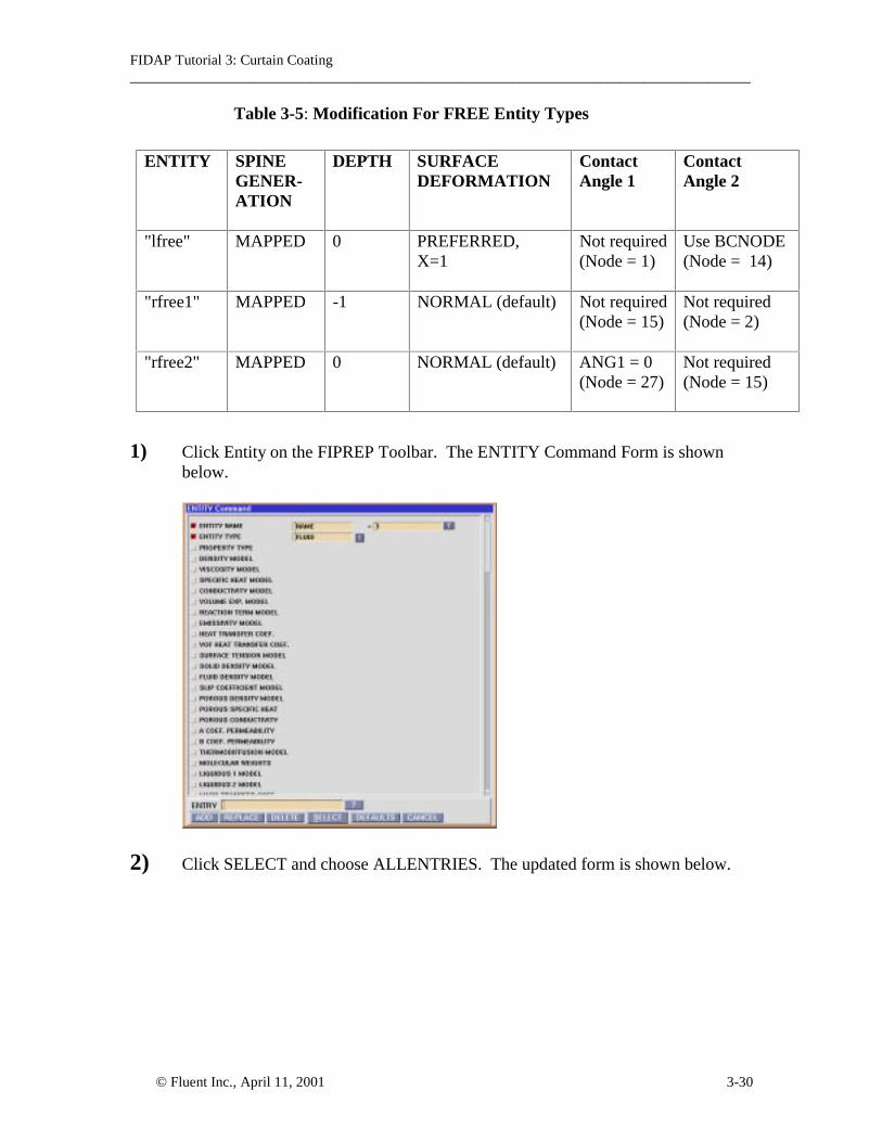
Table 3-5: Modification For FREE Entity Types
ENTITY SPINEGENER-ATION
DEPTH SURFACEDEFORMATION
ContactAngle 1
ContactAngle 2
"lfree" MAPPED 0 PREFERRED,X=1
Not required(Node = 1)
Use BCNODE(Node = 14)
"rfree1" MAPPED -1 NORMAL (default) Not required(Node = 15)
Not required(Node = 2)
"rfree2" MAPPED 0 NORMAL (default) ANG1 = 0(Node = 27)
Not required(Node = 15)
1) Click Entity on the FIPREP Toolbar. The ENTITY Command Form is shownbelow.
2) Click SELECT and choose ALLENTRIES. The updated form is shown below.

FIDAP Tutorial 3: Curtain Coating______________________________________________________________________________________
© Fluent Inc., April 11, 2001 3-31
The FIDAP Command History Window lists all of the ENTITY commands in thecurrent database. Only the commands for the last four entities: "slip", "lfree","rfree1" and "rfree2" need to be modified.
3) To modify the entity "lfree": Click the ? at the bottom of the form and choose"lfree". The updated form is shown below.

FIDAP Tutorial 3: Curtain Coating______________________________________________________________________________________
© Fluent Inc., April 11, 2001 3-32
4) Use the vertical slider bar in the Command Form and scroll down one third of theway until you see the FREE SURFACE DEPTH. Click FREE SURFACEDEPTH and input a value of 0 for the keyword DEPTH. Click PREFERREDDIRECTION -X and input a value of 1 for the keyword X. Click SPINEGENERATION and choose the MAPPED option. The updated form is shownbelow.
5) Move the cursor into the grey area, right click and choose REPLACE(REPEAT).Confirm the change was made correctly by checking the FIDAP CommandHistory Window.

FIDAP Tutorial 3: Curtain Coating______________________________________________________________________________________
© Fluent Inc., April 11, 2001 3-33
6) To modify the entity "rfree1": Click the ? at the bottom of the form and choose"rfree1". Use the vertical slider bar in the Command Form and scroll down untilyou see the FREE SURFACE DEPTH. Click FREE SURFACE DEPTH andinput a value of -1 for the keyword DEPTH. The value -1 (no spine generation) isused here because the maximum depth has already been specified for "lfree".Click SPINE GENERATION and choose the MAPPED option. The updated formis shown below.
7) Move the cursor into the grey area, right click and choose REPLACE(REPEAT).Confirm the change was made correctly by checking the FIDAP CommandHistory Window.
8) To modify the entity "rfree2": Click the ? at the bottom of the form and choose"rfree2". Use the vertical slider bar in the Command Form and scroll down untilyou see the FREE SURFACE DEPTH. Click FREE SURFACE DEPTH andinput a value of 0 for the keyword DEPTH. Click SPINE GENERATION andchoose the MAPPED option. Click CONTACT ANGLE 1 and retain the defaultvalue zero for the keyword ANG1. The updated form is shown below.

FIDAP Tutorial 3: Curtain Coating______________________________________________________________________________________
© Fluent Inc., April 11, 2001 3-34
9) Move the cursor into the grey area, right click and choose REPLACE(REPEAT).Confirm the change was made correctly by checking the FIDAP CommandHistory Window.
10) In Step 13, the SLIPCOEFFICIENT was defined with the SET = "slip". Theproper association with the corresponding entity must be performed. Recall thatthe SET on the SLIPCOEFFICIENT command must match the PROPERTY on theENTITY command. To modify the entity "slip": Click the ? at the bottom of theform and choose "slip". Click PROPERTY TYPE and click the ? to the right of"fluid" to select slip. The updated form is shown below.

FIDAP Tutorial 3: Curtain Coating______________________________________________________________________________________
© Fluent Inc., April 11, 2001 3-35
11) Click REPLACE at the bottom of the form. Confirm the change was madecorrectly by checking the FIDAP Command History Window.
STEP 15: Define the Boundary Conditions
1) Click Boundary C. on the FIPREP Command Toolbar. The BOUNDARY C.Toolbar is shown below.
2) Click BCNODE on the BOUNDARY C. Toolbar. The BCNODE CommandForm is shown below.
Table 3-6 describes the boundary conditions to be applied for the velocity degreesof freedom. Recall that the specific node numbers (needed for boundaryconditions #6-#9) were determined in the FI-BC module in Step 3. It is importantthat boundary conditions #6-#9 are applied after boundary condition #1. Thereason is that the tangential velocity at the dynamic contact point and the nextclosest nodes be free so that the Navier slip boundary condition will be applied atthose nodes. If the order is reversed then the boundary condition #1 willoverwrite boundary conditions #6-#9 and it is likely that convergence will not beachieved.
FIDAP Tutorial 3: Curtain Coating______________________________________________________________________________________
© Fluent Inc., April 11, 2001 3-36
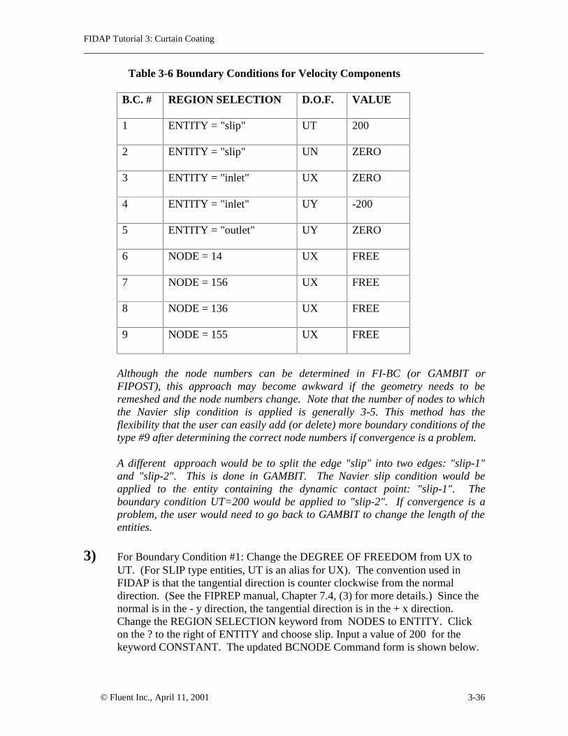
Table 3-6 Boundary Conditions for Velocity Components
B.C. # REGION SELECTION D.O.F. VALUE
1 ENTITY = "slip" UT 200
2 ENTITY = "slip" UN ZERO
3 ENTITY = "inlet" UX ZERO
4 ENTITY = "inlet" UY -200
5 ENTITY = "outlet" UY ZERO
6 NODE = 14 UX FREE
7 NODE = 156 UX FREE
8 NODE = 136 UX FREE
9 NODE = 155 UX FREE
Although the node numbers can be determined in FI-BC (or GAMBIT orFIPOST), this approach may become awkward if the geometry needs to beremeshed and the node numbers change. Note that the number of nodes to whichthe Navier slip condition is applied is generally 3-5. This method has theflexibility that the user can easily add (or delete) more boundary conditions of thetype #9 after determining the correct node numbers if convergence is a problem.
A different approach would be to split the edge "slip" into two edges: "slip-1"and "slip-2". This is done in GAMBIT. The Navier slip condition would beapplied to the entity containing the dynamic contact point: "slip-1". Theboundary condition UT=200 would be applied to "slip-2". If convergence is aproblem, the user would need to go back to GAMBIT to change the length of theentities.
3) For Boundary Condition #1: Change the DEGREE OF FREEDOM from UX toUT. (For SLIP type entities, UT is an alias for UX). The convention used inFIDAP is that the tangential direction is counter clockwise from the normaldirection. (See the FIPREP manual, Chapter 7.4, (3) for more details.) Since thenormal is in the - y direction, the tangential direction is in the + x direction.Change the REGION SELECTION keyword from NODES to ENTITY. Clickon the ? to the right of ENTITY and choose slip. Input a value of 200 for thekeyword CONSTANT. The updated BCNODE Command form is shown below.

FIDAP Tutorial 3: Curtain Coating______________________________________________________________________________________
© Fluent Inc., April 11, 2001 3-37
4) Right click in the grey area in the BCNODE Command form and selectADD(REPEAT). Confirm the change was made correctly by checking theFIDAP Command History Window.
5) For Boundary Condition #2: Change the DEGREE OF FREEDOM keyword fromUT to UN. (For SLIP entities, UN is an alias for UY). Change the value of theVALUE GENERATION keyword from CONSTANT to ZERO. The updatedBCNODE Command form is shown below.

FIDAP Tutorial 3: Curtain Coating______________________________________________________________________________________
© Fluent Inc., April 11, 2001 3-38
6) Right click in the grey area in the BCNODE Command form and selectADD(REPEAT). Confirm the change was made correctly by checking theFIDAP Command History Window.
7) Continue to apply boundary conditions #3, #4, #5 described in Table 3-6.
8) Right click in the grey area in the BCNODE Command form and selectADD(REPEAT). Confirm the change was made correctly by checking the FIDAPCommand History Window.
9) For Boundary Condition #6: Change the DEGREE OF FREEDOM to UX.Change the REGION SELECTION to NODES. Input a value of 14 for keywordNODES. Change the VALUE GENERATION TO FREE. The updatedBCNODE Command form is shown below.
10) Right click in the grey area in the BCNODE Command form and selectADD(REPEAT). Confirm the change was made correctly by checking theFIDAP Command History Window. Repeat this procedure for boundaryconditions #7, #8 and #9 described in Table 3-6.
11) FIDAP does not compute a physically correct normal direction at the cornernodes in the model. For further details, please refer to the FIPREP manual,Chapter 7.4, (2) for an explanation on how to apply physically correct normalsusing the COORDINATE degree of freedom and specifying the node number.Table 3-7 shows the Boundary Conditions for the COORDINATE DEGREE OFFREEDOM.

FIDAP Tutorial 3: Curtain Coating______________________________________________________________________________________
© Fluent Inc., April 11, 2001 3-39
Table 3-7: Boundary Conditions for DEGREE OF FREEDOM = COORDINATE
B.C. # REGION SELECTION D. O. F.
10 NODE = 1 COORDINATE
11 NODE = 2 COORDINATE
12 NODE = 14 COORDINATE
13 NODE = 27 COORDINATE
14 NODE = 28 COORDINATE
For Boundary Condition #10: Change the DEGREE OF FREEDOM toCOORDINATE. Input a value of 1 for the keyword NODES. Click off VALUEGENERATION. The updated form is shown below.

FIDAP Tutorial 3: Curtain Coating______________________________________________________________________________________
© Fluent Inc., April 11, 2001 3-40
12) Right click in the grey area in the BCNODE Command form and selectADD(REPEAT). Confirm the change was made correctly by checking the FIDAPCommand History Window. Repeat this procedure for boundary conditions #11,#12, #13 and #14 described in Table 3-7.
13) The final two boundary conditions are needed to fix the free surface position atnodes 1 and 2. Table 3-8 shows the Boundary conditions needed for theSURFACE DEGREE OF FREEDOM. By specifying a ZERO Value for theSURFACE D.O.F. means that the node is fixed.
Table 3-8: Boundary Conditions forDEGREE OF FREEDOM = SURFACE
B.C. # REGION SELECTION D. O. F. VALUE
15 NODE = 1 SURFACE ZERO
16 NODE = 2 SURFACE ZERO
Boundary Condition #15: Change the DEGREE OF FREEDOM to SURFACE.Input a value of 1 for the NODES keyword. Click VALUE GENERATION andchoose the keyword ZERO. The updated form is shown below.

FIDAP Tutorial 3: Curtain Coating______________________________________________________________________________________
© Fluent Inc., April 11, 2001 3-41
14) Right click in the grey area in the BCNODE Command form and selectADD(REPEAT). Confirm the change was made correctly by checking theFIDAP Command History Window. Repeat for boundary condition #16described in Table 3.8.
15) The value of the contact angle at node 14 is generally determined fromexperiment. Change the DEGREE OF FREEDOM to CONTACTANGLE. Inputa value of 14 for the keyword NODES. Change the VALUE GENERATIONkeyword from ZERO to CONSTANT. Input a value of -20 for the keywordCONSTANT. Input a value of 1 for the keyword X (after the option X/ZCCOMPONENT) to force the movement to be in the horizontal direction. Theupdated form is shown below.
16) Click ADD at the bottom of the form. Confirm the change was made correctly bychecking the FIDAP Command History Window.

FIDAP Tutorial 3: Curtain Coating______________________________________________________________________________________
© Fluent Inc., April 11, 2001 3-42
STEP 16: Apply the Initial Conditions
The default initial condition is zero for all degrees of freedom. Typically a nonzeroinitial condition helps to prevent divergence or improve convergence.
1) Click Initial C. on the FIPREP Menu Toolbar. The ICNODE command Form isshown below.
2) Change the DEGREE OF FREEDOM keyword to UY. Change the I.C. TYPEkeyword from ZERO to CONSTANT and input a value of -200. (You could havealso specified UX = 200). Change the REGION SELECTION keyword fromNODES to ENTITY and select fluid. The updated ICNODE Command Form isshown below.

FIDAP Tutorial 3: Curtain Coating______________________________________________________________________________________
© Fluent Inc., April 11, 2001 3-43
3) Click ADD at the bottom of the ICNODE Command Form. Confirm the changewas made correctly by checking the FIDAP Command History Window.
STEP 17: Scale the Geometry
The actual curtain thickness is .06 cm. To make the geometry easier to create inGAMBIT, the curtain thickness was created to be 1. Therefore, the entire geometry needsto be scaled by a factor of .06, which can be easily done in FIPREP. A scale commandcan be used to multiply all the dimensions in GAMBIT by any factor.
1) Click Mesh Data on the FIPREP Menu Toolbar. The MESH DATA CommandForm is shown below.
2) Click SCALE on the MESH DATA form. The SCALE Command Form isshown below.
3) Click LENGTH SCALE FACTOR and enter a value of .06 for the keywordVALUE. The updated form is shown below.

FIDAP Tutorial 3: Curtain Coating______________________________________________________________________________________
© Fluent Inc., April 11, 2001 3-44
4) Click ADD at the bottom of the form. Confirm the change was made correctly bychecking the FIDAP Command History Window.
STEP 18: End out of the FIPREP Module
Click END on the FIDAP Command Toolbar.
STEP 19: Create the FISOLV Database
1) Click CREATE on the Main Module Toolbar. The Create Toolbar is shownbelow.
2) Click Create on the Create Toolbar. The CREATE Command Form is shownbelow:
The default FILE TYPE is FISOLV.

FIDAP Tutorial 3: Curtain Coating______________________________________________________________________________________
© Fluent Inc., April 11, 2001 3-45
3) Click ACCEPT at the bottom of the CREATE Command Form. The FIDAPCommand History Window will show the following message:
At the beginning of this tutorial, the .FIPREP file was read and a modeldatabase was created. This step updates that model database to also include theproblem specifications: problem type, boundary conditions, physical properties,…. Before attempting to run the simulation, you need to check that the followingmessage is reported in the FIDAP Command History Window:
***FISOLV INPUT DATA SUCCESSFULLY CREATED
If you get error messages, you can NOT proceed to STEP 20: Run the Simulation.To find the source of error you can go back into FIPREP and check the databaseor you can check the .FIINP file that you create next.
4) Click Create on the Create Toolbar. Change the FILE TYPE from FISOLV toFIPREP. Click FILE OPEN STATUS and select the keyword DELETE (tooverwrite any preexisting .FIINP file). The updated CREATE Command Form isshown below.
5) Click ACCEPT at the bottom of the CREATE Command Form.
The file created is named ccoat.FIINP (see Appendix B ). This file contains aclean set of commands and is very useful for diagnosing problems shouldconvergence problems or inaccurate solutions arise. If the database was notcreated in the last step, this file should be checked for errors.

FIDAP Tutorial 3: Curtain Coating______________________________________________________________________________________
© Fluent Inc., April 11, 2001 3-46
STEP 20: Run the Simulation
1) Click RUN on the Main Module Toolbar and select FISOLV. The RUNCommand Form is shown below.
2) Change the RUN keyword from BACKGROUND to FOREGROUND. Theupdated RUN Command Form is shown below.
If you run the simulation in the background, the simulation will continue to run,even if you exit the FIDAP GUI. If you run the simulation in the foreground, youmay display convergence data during the run (via the MONITOR option).
3) Click ACCEPT at the bottom of the RUN Command Form. TheFOREGROUNDTASK IS RUNNING Form is shown below.

FIDAP Tutorial 3: Curtain Coating______________________________________________________________________________________
© Fluent Inc., April 11, 2001 3-47
STEP 21: Monitor the Convergence
1) Click SOLUTION MONITOR at the bottom of the FOREGROUND TASK ISRUNNING Form. The SOLUTION MONITOR Form is shown below.
2) The FIDAP Command History Window will display the first message:
*** RUNNING FISOLV IN THE FOREGROUND WITH IDENTIFIER “ccoat”
Wait for the following message to appear before proceeding to the next step.
Launching the fisolv job with the command line:……
If you click START MONITOR too soon, you will getthe error message in the FIDAP Command History Window:
Solution has not yet begun reporting convergence information.

FIDAP Tutorial 3: Curtain Coating______________________________________________________________________________________
© Fluent Inc., April 11, 2001 3-48
3) Click START MONITOR at the bottom of the SOLUTION MONITOR Form.The Convergence Form is shown below. A discussion of the convergence plotwill be given in STEP 23.
4) When the solution reaches convergence (735 iterations), click DONE at thebottom of the Convergence Form.
FIDAP Tutorial 3: Curtain Coating______________________________________________________________________________________
© Fluent Inc., April 11, 2001 3-49
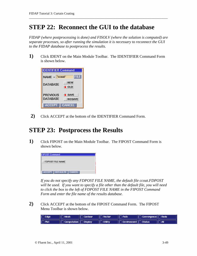
STEP 22: Reconnect the GUI to the database
FIDAP (where postprocessing is done) and FISOLV (where the solution is computed) areseparate processes, so after running the simulation it is necessary to reconnect the GUIto the FIDAP database to postprocess the results.
1) Click IDENT on the Main Module Toolbar. The IDENTIFIER Command Formis shown below.
2) Click ACCEPT at the bottom of the IDENTIFIER Command Form.
STEP 23: Postprocess the Results
1) Click FIPOST on the Main Module Toolbar. The FIPOST Command Form isshown below.
If you do not specify any FDPOST FILE NAME, the default file ccoat.FDPOSTwill be used. If you want to specify a file other than the default file, you will needto click the box to the left of FDPOST FILE NAME in the FIPOST CommandForm and enter the file name of the results database.
2) Click ACCEPT at the bottom of the FIPOST Command Form. The FIPOSTMenu Toolbar is shown below.

FIDAP Tutorial 3: Curtain Coating______________________________________________________________________________________
© Fluent Inc., April 11, 2001 3-50
3) Check the Convergence. Click Convergence on the FIPOST Menu Toolbar. TheCONVERGENCE Command Form is shown below.
Change the Y AXIS SCALE keyword from LINEAR to LOG. The updatedCONVERGENCE Command is shown below.
Click ACCEPT at the bottom of the form. The Convergence Plot is shown below.The stairstep nature is typical of free surface convergence histories using thesegregated solver in which the velocity field is solved until convergence, and thenthe free surface is updated, after which the velocity field must be solved againwith the new free surface. This sequence is continued until both velocity and freesurfaces are converged.
Figure 3-3: Convergence History

FIDAP Tutorial 3: Curtain Coating______________________________________________________________________________________
© Fluent Inc., April 11, 2001 3-51
4) To specify a title for the plots, click on All in the FIPREP toolbar and selectTITLE.
Click ACCEPT on the TITLE Command Form. The DATA NEEDED buttonwill appear and you will be prompted to enter data. Press the F2 key and type inthe Command Prompt Window:
Curtain Coating: Re = 2.85, Ca = 35.13
Press the Enter Key.
5) Even though the solution has converged, it is a good idea to verify that theboundary conditions have been correctly applied. This can be done in theFIPOST module, however it is only a qualitative check. This step could havealso been done after Step 19: creation of the DATABASE and before Step 20: runthe simulation. It is also a good trouble shooting strategy if convergence is aproblem. Click Mesh on the FIPREP module. The MESH Command Form willappear. Click NODAL D.O.F. and change the keyword from VELOCITY to UX.Click ADD in the MESH Command form. The updated MESH Command Formis shown below.

FIDAP Tutorial 3: Curtain Coating______________________________________________________________________________________
© Fluent Inc., April 11, 2001 3-52
Click ACCEPT in the MESH Command form. Slide the PAN/ZOOM bar(located in the Graphics Control Window) to the left slightly to better view theentire model. The boundary conditions will be designated by arrows pointing tothe right or upwards (indicating a positive boundary condition), arrows pointingto the left or downwards (indicating a negative boundary condition) or zeros(indicating a zero boundary condition). Arrows will be colored from red (largestmagnitude) to blue (smallest magnitude). In the figure below, you will see redarrows pointing to the right at all of the nodes on the entity "slip", except for thefirst four nodes (indicating a positive ux boundary condition). There are zeroson all of the nodes at the "inlet" (indicating a zero UX boundary condition).
Figure 3-4: Mesh Plot and UX Boundary Condition.

FIDAP Tutorial 3: Curtain Coating______________________________________________________________________________________
© Fluent Inc., April 11, 2001 3-53
Performing a similar check on the UY boundary conditions gives the plot shownbelow. There are red arrows pointing to the left at the "inlet" (indicating a largenegative boundary condition for UY). There are zeros on all nodes on the "outlet"and "slip" (indicating a zero UY boundary condition).
Figure 3-5: Mesh Plot and UY Boundary Condition.
6) Plot the free surface movement. Click FREE on the All Menu and clickACCEPT. The original shape is white. The final free surface shape is shown ingreen. The left free surface bulges to the left creating a small heel.
Figure 3-6: Movement of Free Surface
Original Surface (white)
Free Surface (green)

FIDAP Tutorial 3: Curtain Coating______________________________________________________________________________________
© Fluent Inc., April 11, 2001 3-54
7) Plot the streamline contours. The Plot shows smooth contours in the entireregion. There are no recirculation zones (closed contours) in the heel region.
Figure 3-7: Streamline Contours
8) Create a Vector Plot: Click Vector on the FIPOST Menu Toolbar. ClickACCEPT on the bottom of the VECTOR Command Form. The Vector plot isshown below. You may need to use the PAN/ZOOM slider bar in the GraphicsControl Window to scale the plot to fit.
Figure 3-8: Vector Field

FIDAP Tutorial 3: Curtain Coating______________________________________________________________________________________
© Fluent Inc., April 11, 2001 3-55
9) Plot the pressure contours. Note the spike in the pressure in the heel region. Thisis due to the velocity discontinuity at the dynamic contact point.
Figure 3-9: Pressure Contours
STEP 24: Exit the FIPOST module
Click END on the FIDAP Command Toolbar to end out of the FIPOST moduleand return to the FIDAP root level.
STEP 25: Exit FIDAP
Click END on the FIDAP Command Toolbar to end out of FIDAP. Click YES atthe EXIT PROMPT Form.

FIDAP Tutorial 3: Curtain Coating______________________________________________________________________________________
© Fluent Inc., April 11, 2001 3-56
SUMMARY:
In this tutorial the ratio of the speeds of the falling curtain and the moving substrate areequal. When the Reynolds number is low, FIDAP predicts a small heel formation. Thisis consistent with previously published results (1). The user can easily change the values:width and speed of the falling curtain, speed of the moving substrate, density, viscosity,and surface tension of the fluid for a new set of conditions. The recommended approachis to edit the file ccoat.FIINP (which was created in Step 19, #4) by uncommenting outsome of the commands, inserting the necessary parameters and adding some commands.For more details on this procedure, please refer to Lecture 5 of the FIDAP IntroductoryLecture Note. The basic steps are:
1. Copy the file ccoat.FIINP to the file ccoat_p.FDREAD and make the followingchanges to the file ccoat_p.FDREAD.
2. Uncomment out the 3 lines:FICONV(NEUTRAL,NORESULTS,INPUT)INPUT(FILE="ccoat.FDNEUT")END
3. Insert the parameterized values. An example of just one of the values is given by:$vel_c = 200
4. REPLACE the necessary FIPREP commands with the parameterized values.Change fromBCNO(UY, ENTI("inlet", CONS = -200.)
toBCNO(UY, ENTI="inlet", CONS = -$vel_c)
5. After the command PARAMETER (LIST), add the RUN Command:RUN(FISOLV,FORE)
6. Insert the POSTPROCESSING commands:IDENT(NAME = "ccoat_p")FIPOSTDEVI(XWIN)CONVERGENCE (ALL,LOG)MESH(BCNO,UX)MESH(BCNO(UY)FREECONT (STREAMLINE)VECTORCONTOUR (PRES)END
An example input file (named ccoat_p.FDREAD) is provided in Appendix C.
REFERENCES:1. Kistler, Stephan F. and Schweizer, Peter M. (1997), Liquid Film Coating: Scientificprinciples and their technological implications, Chapman and Hall, London.
FIDAP Tutorial 3: Curtain Coating______________________________________________________________________________________
© Fluent Inc., April 11, 2001 3-57
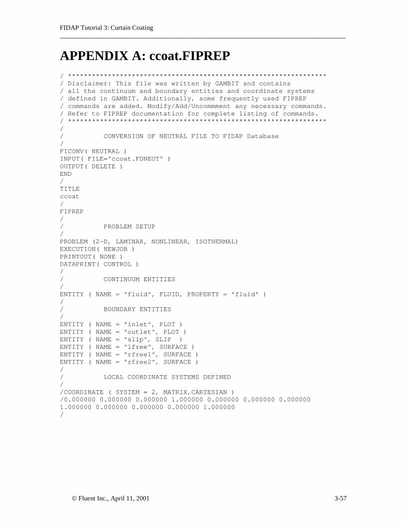
APPENDIX A: ccoat.FIPREP/ *****************************************************************/ Disclaimer: This file was written by GAMBIT and contains/ all the continuum and boundary entities and coordinate systems/ defined in GAMBIT. Additionally, some frequently used FIPREP/ commands are added. Modify/Add/Uncommment any necessary commands./ Refer to FIPREP documentation for complete listing of commands./ *****************************************************************// CONVERSION OF NEUTRAL FILE TO FIDAP Database/FICONV( NEUTRAL )INPUT( FILE="ccoat.FDNEUT" )OUTPUT( DELETE )END/TITLEccoat/FIPREP// PROBLEM SETUP/PROBLEM (2-D, LAMINAR, NONLINEAR, ISOTHERMAL)EXECUTION( NEWJOB )PRINTOUT( NONE )DATAPRINT( CONTROL )// CONTINUUM ENTITIES/ENTITY ( NAME = "fluid", FLUID, PROPERTY = "fluid" )// BOUNDARY ENTITIES/ENTITY ( NAME = "inlet", PLOT )ENTITY ( NAME = "outlet", PLOT )ENTITY ( NAME = "slip", SLIP )ENTITY ( NAME = "lfree", SURFACE )ENTITY ( NAME = "rfree1", SURFACE )ENTITY ( NAME = "rfree2", SURFACE )// LOCAL COORDINATE SYSTEMS DEFINED//COORDINATE ( SYSTEM = 2, MATRIX,CARTESIAN )/0.000000 0.000000 0.000000 1.000000 0.000000 0.000000 0.0000001.000000 0.000000 0.000000 0.000000 1.000000/

FIDAP Tutorial 3: Curtain Coating______________________________________________________________________________________
© Fluent Inc., April 11, 2001 3-58
/ SOLUTION PARAMETERS//SOLUTION( S.S. = 10, VELCONV = .01, RESCONV = .01, ACCF = .0 )/PRESSURE( PENALTY = 1.E-6, DISCONTINUOUS )/OPTIONS( UPWINDING, , , )/SCALE( VALUE = 1 )/TIMEINTEGRATION( BACKWARD,NSTEPS = ,DT = 0,,, )/POSTPROCESS( NBLOCKS = )// MATERIAL PROPERTIES// Partial list of Material Properties data//The following lines were uncommented. This step will not be necessary/in GAMBIT versions 2.0 and later.DENSITY( SET = "fluid", CONSTANT = 1 )VISCOSITY( SET = "fluid", CONSTANT = 1 )/CONDUCTIVITY( SET = "fluid", CONSTANT = 1 )/SPECIFICHEAT( SET = "fluid", CONSTANT = 1 )// INITIAL AND BOUNDARY CONDITIONS//ICNODE( , CONSTANT = 0, ALL )//BCNODE( , CONSTANT = 0, ENTITY = "inlet" )/BCNODE( , CONSTANT = 0, ENTITY = "outlet" )/BCNODE( , CONSTANT = 0, ENTITY = "slip" )/BCNODE( , CONSTANT = 0, ENTITY = "lfree" )/BCNODE( , CONSTANT = 0, ENTITY = "rfree1" )/BCNODE( , CONSTANT = 0, ENTITY = "rfree2" )/END/CREATE( FIPREP,DELETE )PARAMETER( LIST )CREATE( FISOLV )/RUN( FISOLV, FOREGROUND )

FIDAP Tutorial 3: Curtain Coating______________________________________________________________________________________
© Fluent Inc., April 11, 2001 3-59
APPENDIX B: ccoat.FIINP// FICONV(NEUTRAL,NORESULTS,INPUT)/ INPUT(FILE= "ccoat.FDNEUT")/ END/TITLE/FIPREP PROB (2-D, STEA, INCO, LAMI, NONL, NEWT, MOME, ISOT, FREE, SING) PRES (MIXE, DISC) EXEC (NEWJ) SOLU (SEGR = 100, VELC = 0.100000000000E-03, SURF = 0.100000000000E-02, PREC = 21, KINE = 500) DATA (NONE) RELA (HYBR) 0.3000000000E+00, 0.3000000000E+00, 0.0000000000E+00, 0.5000000000E+00, 0.0000000000E+00, 0.9750000000E+00, 0.0000000000E+00, 0.0000000000E+00, 0.0000000000E+00, 0.0000000000E+00, 0.0000000000E+00, 0.0000000000E+00, 0.0000000000E+00, 0.0000000000E+00, 0.0000000000E+00, 0.0000000000E+00, 0.0000000000E+00, 0.0000000000E+00, 0.0000000000E+00, 0.0000000000E+00, 0.0000000000E+00, 0.0000000000E+00, 0.0000000000E+00, 0.0000000000E+00, 0.0000000000E+00, 0.0000000000E+00, 0.0000000000E+00, 0.0000000000E+00 PRIN (NONE) SCAL (VALU = 0.600000000000E-01)
ENTI (NAME = "fluid", FLUI, PROPERTY ="fluid") ENTI (NAME = "inlet", PLOT) ENTI (NAME = "outlet", PLOT) ENTI (NAME = "slip", SLIP, PROPERTY = "slip") ENTI (NAME = "lfree", SURF, DEPT = 0, X = 1.0, MAPP) ENTI (NAME = "rfree1", SURF, DEPT = -1, MAPP, NORM) ENTI (NAME = "rfree2", SURF, DEPT = 0, MAPP, NORM, ANG1 = 0.0)
DENS (SET = "fluid", CONS = 1.25) VISC (SET = "fluid", CONS = 5.27) SURF (SET = "fluid", CONS = 30.0) SLIP (SET = "slip", CONS = 0.100000000000E-01, UT = 200.0)

FIDAP Tutorial 3: Curtain Coating______________________________________________________________________________________
© Fluent Inc., April 11, 2001 3-60
BCNO (UT, ENTI = "slip", CONS = 200.0) BCNO (UN, ENTI = "slip", ZERO) BCNO (UX, ENTI = "inlet", ZERO) BCNO (UY, ENTI = "inlet", CONS = -200.0) BCNO (UY, ENTI = "outlet", ZERO)
BCNO (CONT, CONS = -20.0, NODE = 14, X = 1.0, Y = 0.0)
BCNO (UX, NODE = 14, FREE) BCNO (UX, NODE = 156, FREE) BCNO (UX, NODE = 136, FREE) BCNO (UX, NODE = 155, FREE)
BCNO (COOR, NODE = 1) BCNO (COOR, NODE = 2) BCNO (COOR, NODE = 14) BCNO (COOR, NODE = 27) BCNO (COOR, NODE = 28) BCNO (SURF, NODE = 1, ZERO) BCNO (SURF, NODE = 2, ZERO)
ICNO (UY, CONS = -200.0, ENTI = "fluid")END/ *** of FIPREP CommandsCREATE(FIPREP,DELE)CREATE(FISOLV)PARAMETER(LIST)

FIDAP Tutorial 3: Curtain Coating______________________________________________________________________________________
© Fluent Inc., April 11, 2001 3-61
APPENDIX C: ccoat_p.FDREAD/ccoat_p.FDREAD/This is a parameterized file for a curtain coating problem./This file both runs the simulation and postprocesses the results./To run this file type the command:/fidap -id ccoat_p -in ccoat_p.FDREAD -new/Note: The file ccoat.FDNEUT must also be in your working directory./
FICONV(NEUTRAL,NORESULTS,INPUT)INPUT(FILE= "ccoat.FDNEUT")END//units are CGS//scale geometry in GAMBIT so that characteristic length at outlet/ is .06 cm/length units are cm$length = .06
/scale factor$scfac = $length
/density units are g/m3$density = 1.25
/viscosity units are g/(cm-s)$viscosity = 5.27
/surface tension units are g/s2$surftens = 30.0
/velocity units of falling curtain and moving substrate are cm/s$vel_c = 200$vel_s = 200
/slip coefficient$slipcoef = .01
/contact angle units are degrees$contangle = 20
/Reynolds number and Capillary number at "outlet"$Re = $density * $vel_s * $length / $viscosity$Ca = $viscosity * $vel_s / $surftens
/Relaxation values for velocity, pressure and free surface d.o.f.$vel_rel = .3$pre_rel = .5$sur_rel = .975

FIDAP Tutorial 3: Curtain Coating______________________________________________________________________________________
© Fluent Inc., April 11, 2001 3-62
/title information$fr = 100$fc = 100$Re1 = 100 * $Re$Re2 = INT ($Re1)$Re3 = ($Re2/$fr)
$Ca1 = 100 * $Ca$Ca2 = INT ($Ca1)$Ca3 = ($Ca2/$fc)
$head = "Curtain Coating:"$rtitle = " Re = " + NTOS ($Re3)$ctitle = " Ca = " + NTOS ($Ca3)
TITLE (String)($head + $rtitle + $ctitle)
FIPREP PROB (2-D, STEA, INCO, LAMI, NONL, NEWT, MOME, ISOT, FREE, SING) PRES (MIXE, DISC) EXEC (NEWJ) SOLU (SEGR = 100, VELC = 0.1E-03, SURF = 0.1E-02, PREC = 21, KINE =500) DATA (NONE) RELA (HYBR)/ U V W P T S $vel_rel $vel_rel 0 $pre_rel 0 $sur_rel PRIN (NONE) SCAL (VALU = $scfac)
ENTI (NAME = "fluid", FLUI, PROP = "fluid") ENTI (NAME = "inlet", PLOT) ENTI (NAME = "outlet", PLOT) ENTI (NAME = "slip", SLIP, PROP = "slip" ) ENTI (NAME = "lfree", SURF, DEPT = 0, MAPP, X = 1.0) ENTI (NAME = "rfree1", SURF, DEPT = -1, MAPP, NORM) ENTI (NAME = "rfree2", SURF, DEPT = 0, MAPP, NORM, ANG1 = 0.0)
DENS (SET = "fluid", CONS = $density) VISC (SET = "fluid", CONS = $viscosity) SURF (SET = "fluid", CONS = $surftens) SLIP (SET = "slip", CONS = $slipcoef, UT = $vel_s)

FIDAP Tutorial 3: Curtain Coating______________________________________________________________________________________
© Fluent Inc., April 11, 2001 3-63
BCNO (UT, ENTI = "slip", CONS = $vel_s) BCNO (UN, ENTI = "slip", ZERO) BCNO (UX, ENTI = "inlet", ZERO) BCNO (UY, ENTI = "inlet", CONS = -$vel_c) BCNO (UY, ENTI = "outlet", ZERO) BCNO (CONT, CONS = $contangle, NODE = 14, X = 1.0, Y = 0.0) BCNO (UX, NODE = 14, FREE) BCNO (UX, NODE = 156, FREE) BCNO (UX, NODE = 136, FREE) BCNO (UX, NODE = 155, FREE) BCNO (COOR, NODE = 1) BCNO (COOR, NODE = 2) BCNO (COOR, NODE = 14) BCNO (COOR, NODE = 27) BCNO (COOR, NODE = 28) BCNO (SURF, NODE = 1, ZERO) BCNO (SURF, NODE = 2, ZERO)
ICNO (UY, CONS = -$vel_c, ENTI = "fluid")END
CREATE(FIPREP,DELE)CREATE(FISOLV)PARAMETER(LIST)RUN(FISOLV,FORE)
IDENT(NAME="ccoat_p")
FIPOSTDEVI(XWIN)CONVERGENCE( ALL, LOG )MESH( BCNO, UX )MESH( BCNO, UY )FREECONT(STREAMLINE)VECTOR( )CONTOUR( PRES )END