fictitious architects court house project
TRANSCRIPT

COURT HOUSE PROJECT
Fictitious Architects
Presented by Ryan Rigsbee
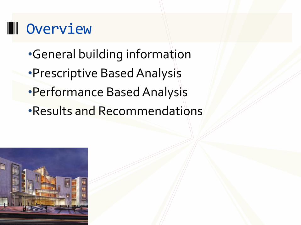
•General building information
•Prescriptive Based Analysis
•Performance Based Analysis
•Results and Recommendations
Overview
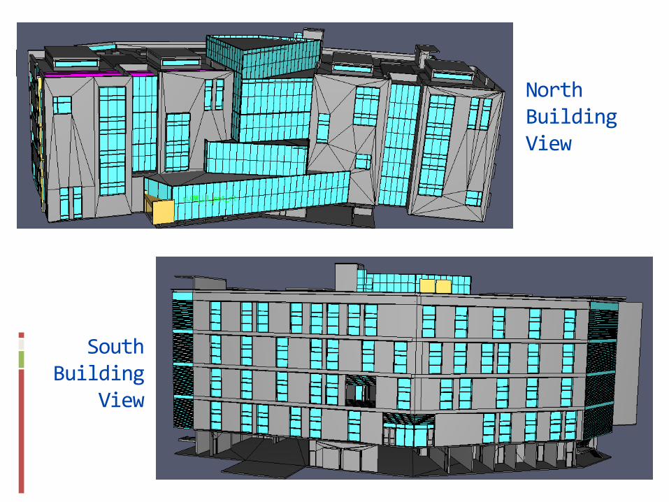
North Building View
South Building
View
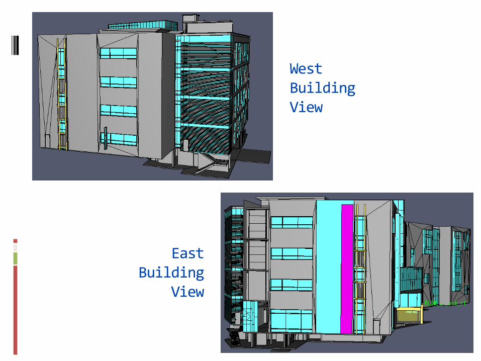
East Building
View
West Building View
General Building Information
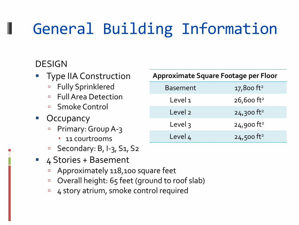
DESIGN
Type IIA Construction Fully Sprinklered Full Area Detection Smoke Control
Occupancy Primary: Group A-3
11 courtrooms
Secondary: B, I-3, S1, S2
4 Stories + Basement Approximately 118,100 square feet Overall height: 65 feet (ground to roof slab) 4 story atrium, smoke control required
Approximate Square F00tage per Floor
Basement 17,800 ft2
Level 1 26,600 ft2
Level 2 24,300 ft2
Level 3 24,900 ft2
Level 4 24,500 ft2
General Building Information
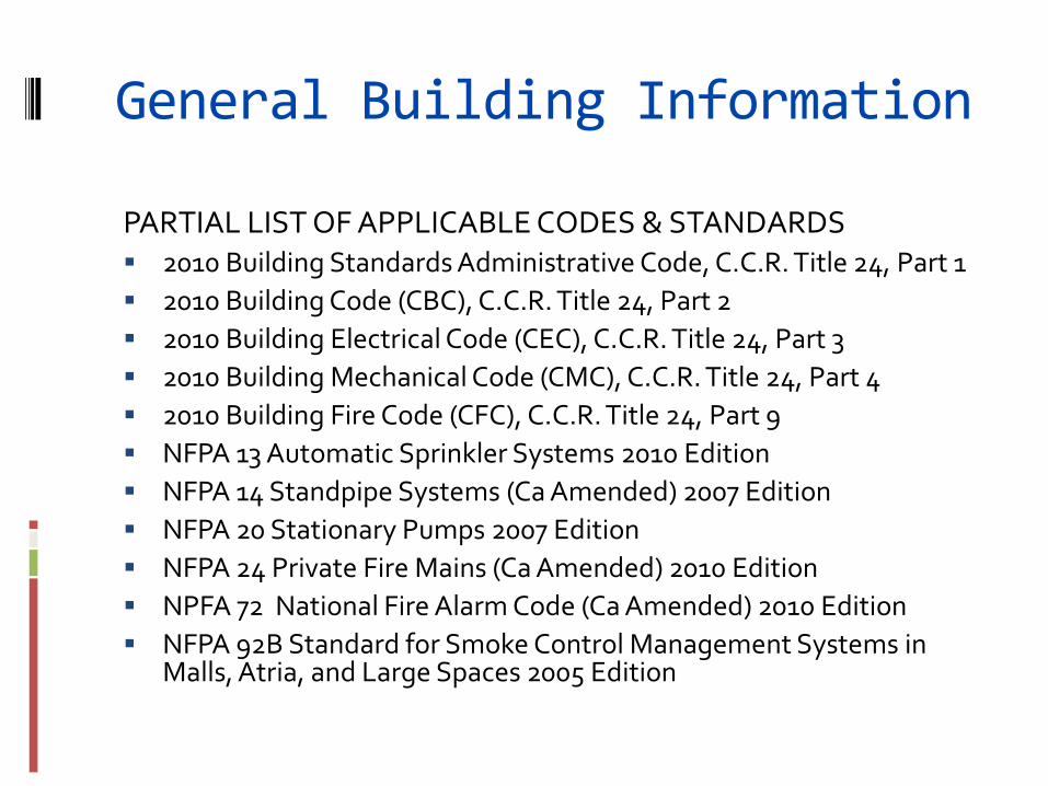
PARTIAL LIST OF APPLICABLE CODES & STANDARDS 2010 Building Standards Administrative Code, C.C.R. Title 24, Part 1
2010 Building Code (CBC), C.C.R. Title 24, Part 2
2010 Building Electrical Code (CEC), C.C.R. Title 24, Part 3
2010 Building Mechanical Code (CMC), C.C.R. Title 24, Part 4
2010 Building Fire Code (CFC), C.C.R. Title 24, Part 9
NFPA 13 Automatic Sprinkler Systems 2010 Edition
NFPA 14 Standpipe Systems (Ca Amended) 2007 Edition
NFPA 20 Stationary Pumps 2007 Edition
NFPA 24 Private Fire Mains (Ca Amended) 2010 Edition
NPFA 72 National Fire Alarm Code (Ca Amended) 2010 Edition
NFPA 92B Standard for Smoke Control Management Systems in Malls, Atria, and Large Spaces 2005 Edition
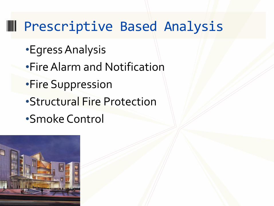
•Egress Analysis
•Fire Alarm and Notification
•Fire Suppression
•Structural Fire Protection
•Smoke Control
Prescriptive Based Analysis
Egress Analysis
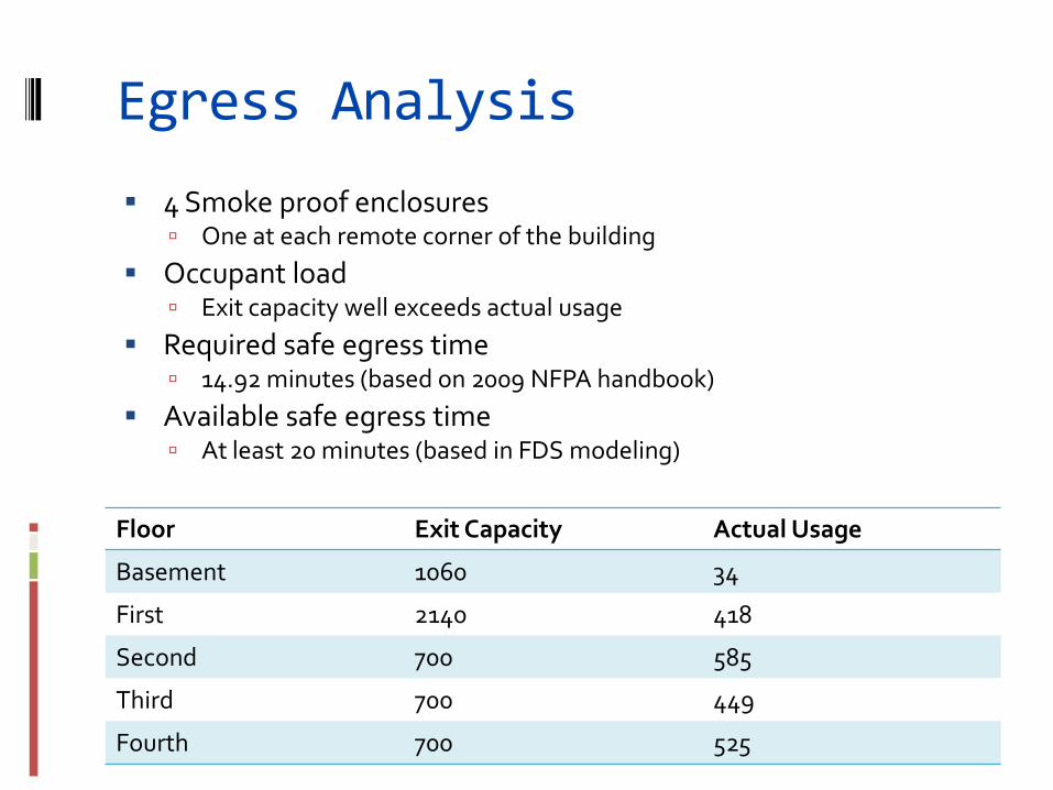
4 Smoke proof enclosures One at each remote corner of the building
Occupant load Exit capacity well exceeds actual usage
Required safe egress time 14.92 minutes (based on 2009 NFPA handbook)
Available safe egress time At least 20 minutes (based in FDS modeling)
Floor Exit Capacity Actual Usage
Basement 1060 34
First 2140 418
Second 700 585
Third 700 449
Fourth 700 525
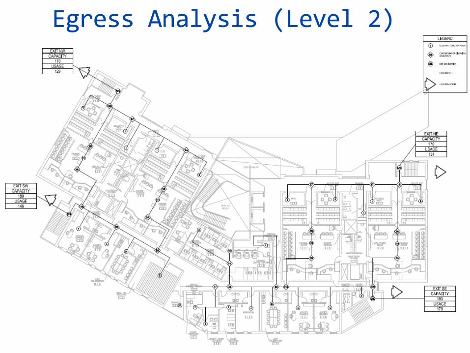
Egress Analysis (Level 2)
Fire Alarm and Signaling
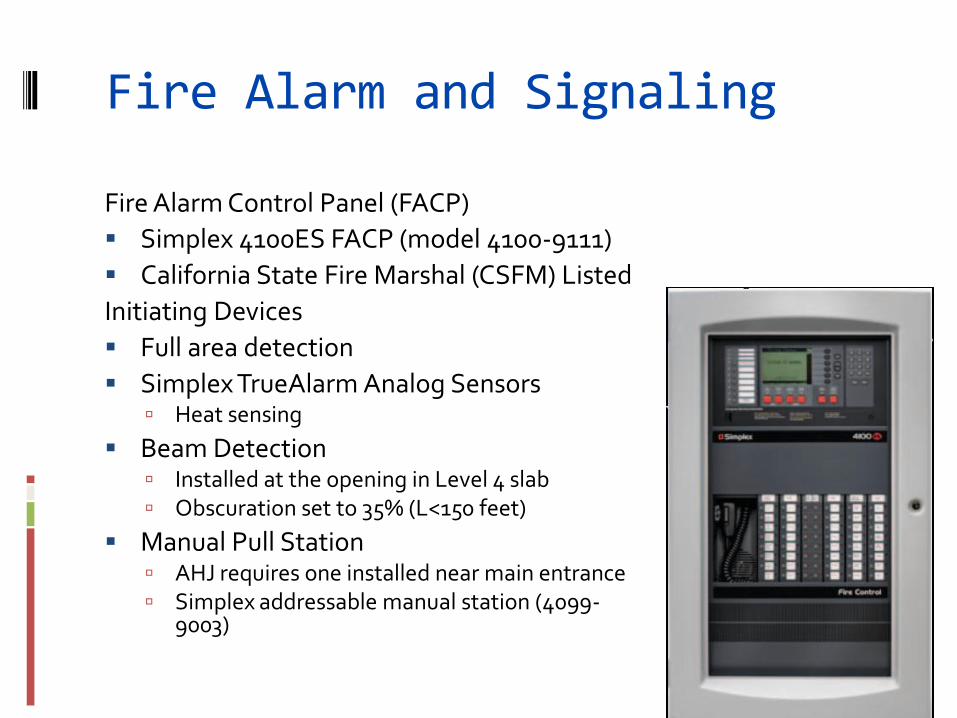
Fire Alarm Control Panel (FACP)
Simplex 4100ES FACP (model 4100-9111)
California State Fire Marshal (CSFM) Listed
Initiating Devices
Full area detection
Simplex TrueAlarm Analog Sensors Heat sensing
Beam Detection Installed at the opening in Level 4 slab Obscuration set to 35% (L<150 feet)
Manual Pull Station AHJ requires one installed near main entrance Simplex addressable manual station (4099-
9003)
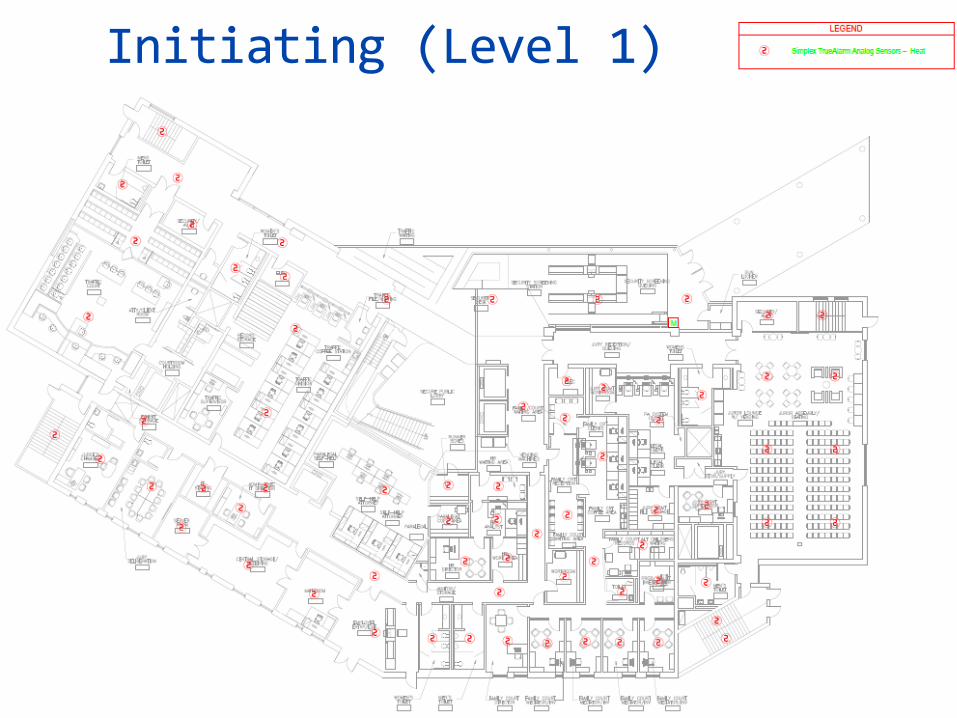
Initiating (Level 1)
Fire Alarm and Signaling
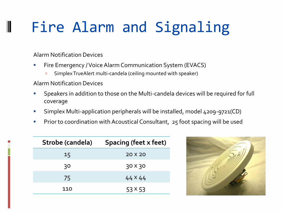
Alarm Notification Devices
Fire Emergency / Voice Alarm Communication System (EVACS)
Simplex TrueAlert multi-candela (ceiling mounted with speaker)
Alarm Notification Devices
Speakers in addition to those on the Multi-candela devices will be required for full coverage
Simplex Multi-application peripherals will be installed, model 4209-9721(CD)
Prior to coordination with Acoustical Consultant, 25 foot spacing will be used
Strobe (candela) Spacing (feet x feet)
15 20 x 20
30 30 x 30
75 44 x 44
110 53 x 53
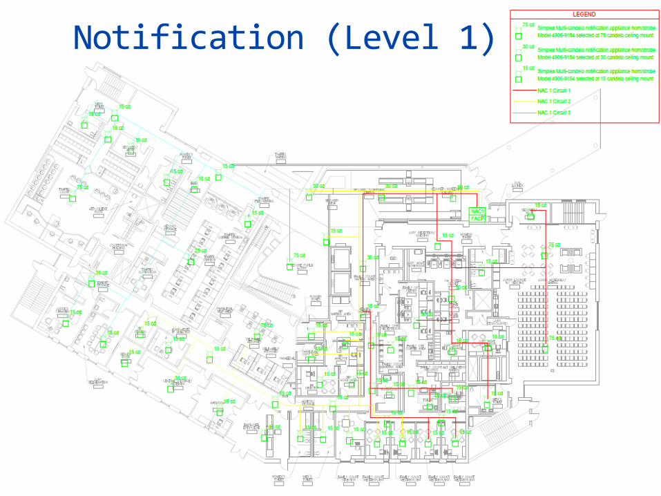
Notification (Level 1)
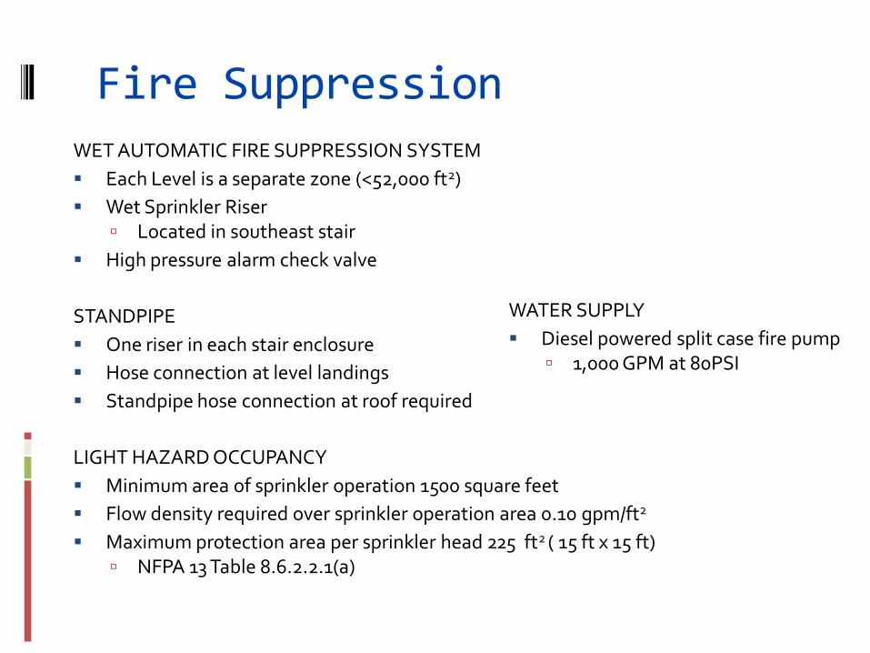
Fire Suppression WET AUTOMATIC FIRE SUPPRESSION SYSTEM
Each Level is a separate zone (<52,000 ft2)
Wet Sprinkler Riser Located in southeast stair
High pressure alarm check valve
STANDPIPE
One riser in each stair enclosure
Hose connection at level landings
Standpipe hose connection at roof required
LIGHT HAZARD OCCUPANCY
Minimum area of sprinkler operation 1500 square feet
Flow density required over sprinkler operation area 0.10 gpm/ft2
Maximum protection area per sprinkler head 225 ft2 ( 15 ft x 15 ft) NFPA 13 Table 8.6.2.2.1(a)
WATER SUPPLY
Diesel powered split case fire pump 1,000 GPM at 80PSI
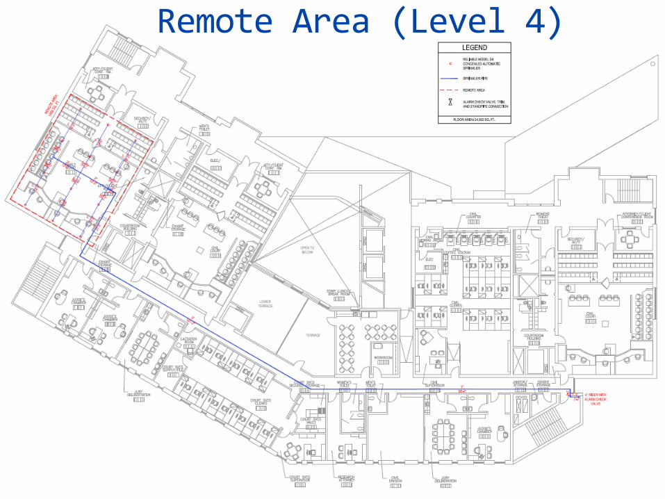
Remote Area (Level 4)
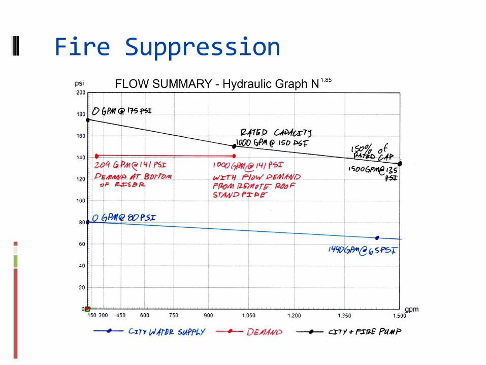
Fire Suppression
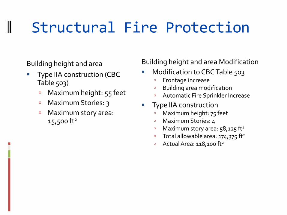
Structural Fire Protection
Building height and area
Type IIA construction (CBC Table 503)
Maximum height: 55 feet
Maximum Stories: 3
Maximum story area: 15,500 ft2
Building height and area Modification
Modification to CBC Table 503 Frontage increase Building area modification Automatic Fire Sprinkler Increase
Type IIA construction Maximum height: 75 feet Maximum Stories: 4 Maximum story area: 58,125 ft2 Total allowable area: 174,375 ft2
Actual Area: 118,100 ft2
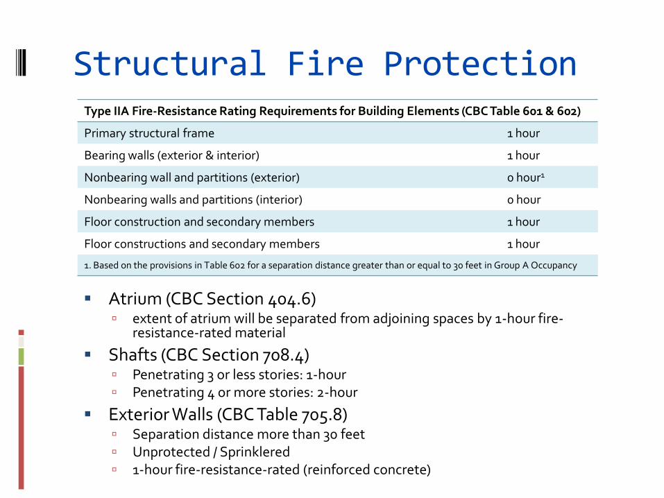
Structural Fire Protection
Type IIA Fire-Resistance Rating Requirements for Building Elements (CBC Table 601 & 602)
Primary structural frame 1 hour
Bearing walls (exterior & interior) 1 hour
Nonbearing wall and partitions (exterior) 0 hour1
Nonbearing walls and partitions (interior) 0 hour
Floor construction and secondary members 1 hour
Floor constructions and secondary members 1 hour
1. Based on the provisions in Table 602 for a separation distance greater than or equal to 30 feet in Group A Occupancy
Atrium (CBC Section 404.6) extent of atrium will be separated from adjoining spaces by 1-hour fire-
resistance-rated material
Shafts (CBC Section 708.4) Penetrating 3 or less stories: 1-hour Penetrating 4 or more stories: 2-hour
Exterior Walls (CBC Table 705.8) Separation distance more than 30 feet Unprotected / Sprinklered 1-hour fire-resistance-rated (reinforced concrete)
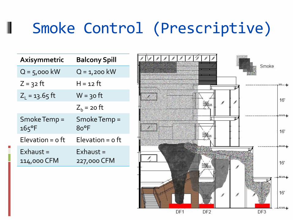
Smoke Control (Prescriptive)
Axisymmetric Balcony Spill
Q = 5,000 kW Q = 1,200 kW
Z = 32 ft H = 12 ft
ZL = 13.65 ft W = 30 ft
Zb = 20 ft
Smoke Temp = 165°F
Smoke Temp = 80°F
Elevation = 0 ft Elevation = 0 ft
Exhaust = 114,000 CFM
Exhaust = 227,000 CFM
•Egress Analysis
•Smoke control
Performance Based Analysis
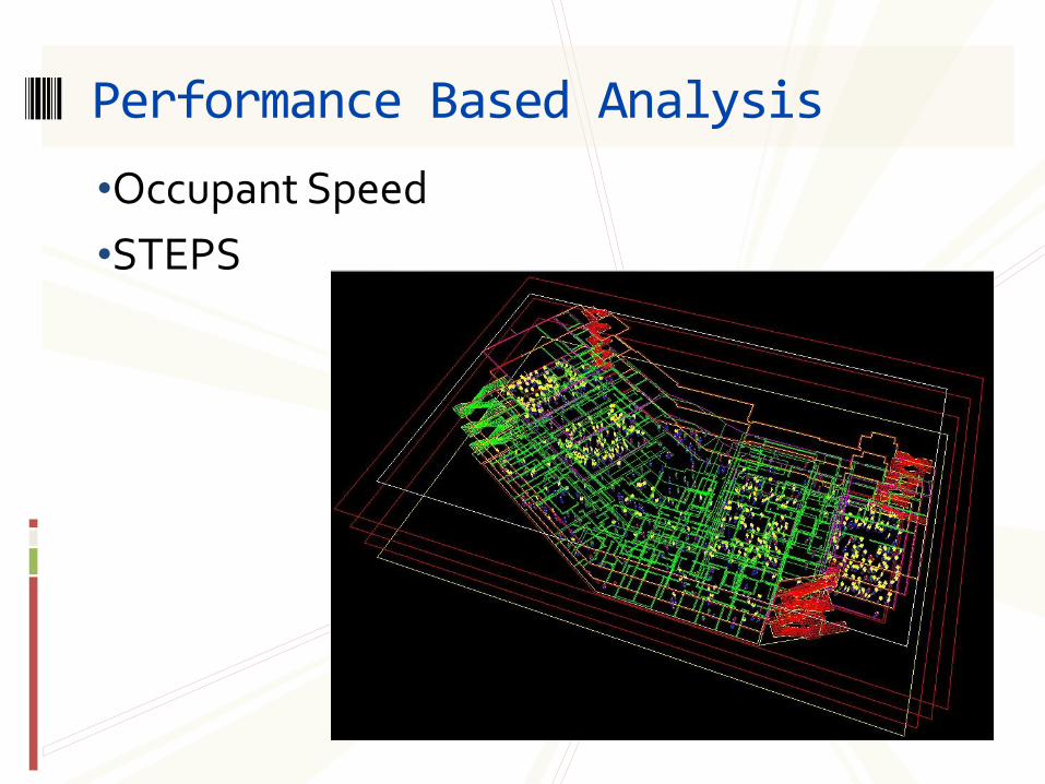
•Occupant Speed
•STEPS
Performance Based Analysis
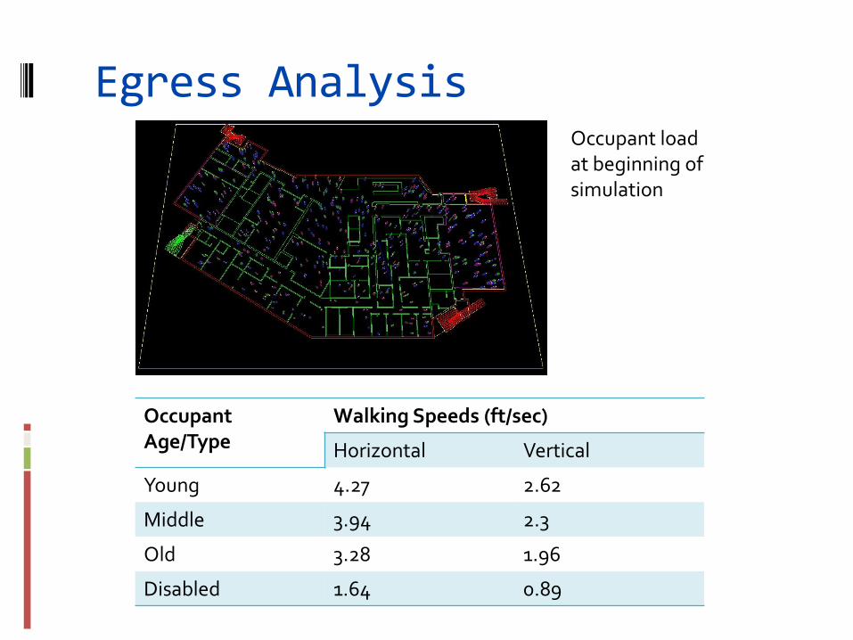
Egress Analysis
Occupant Age/Type
Walking Speeds (ft/sec)
Horizontal Vertical
Young 4.27 2.62
Middle 3.94 2.3
Old 3.28 1.96
Disabled 1.64 0.89
Occupant load at beginning of simulation
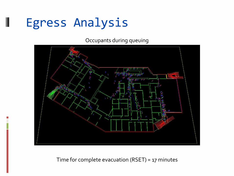
Egress Analysis Occupants during queuing
Time for complete evacuation (RSET) = 17 minutes
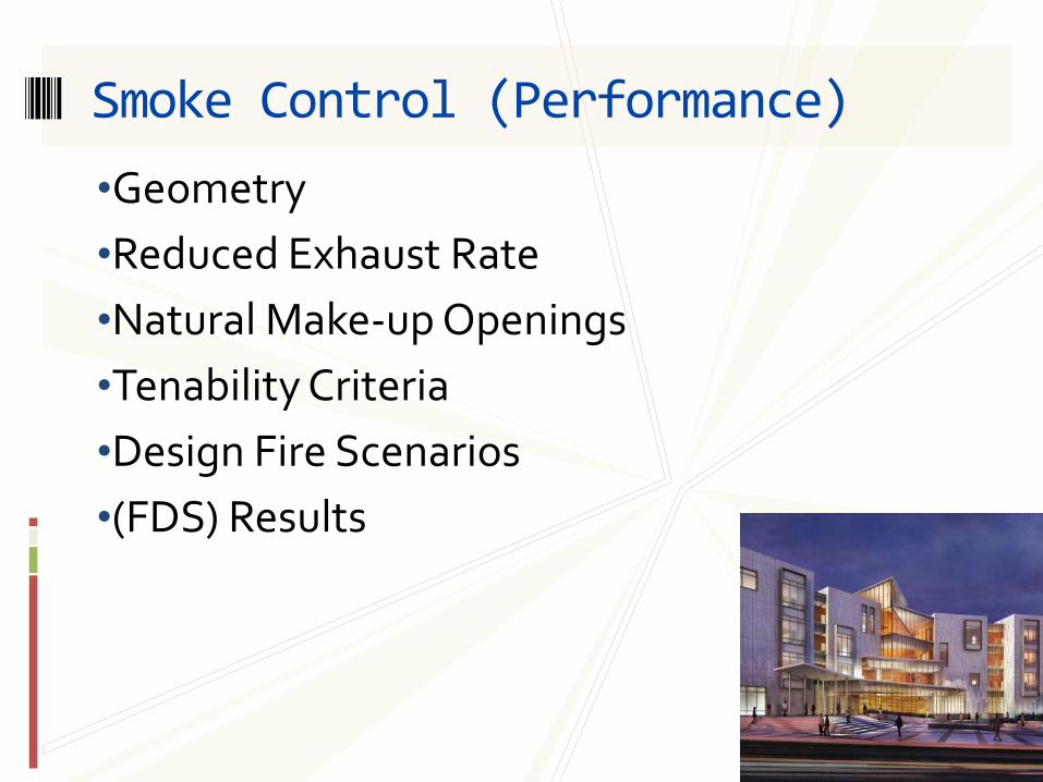
•Geometry
•Reduced Exhaust Rate
•Natural Make-up Openings
•Tenability Criteria
•Design Fire Scenarios
•(FDS) Results
Smoke Control (Performance)
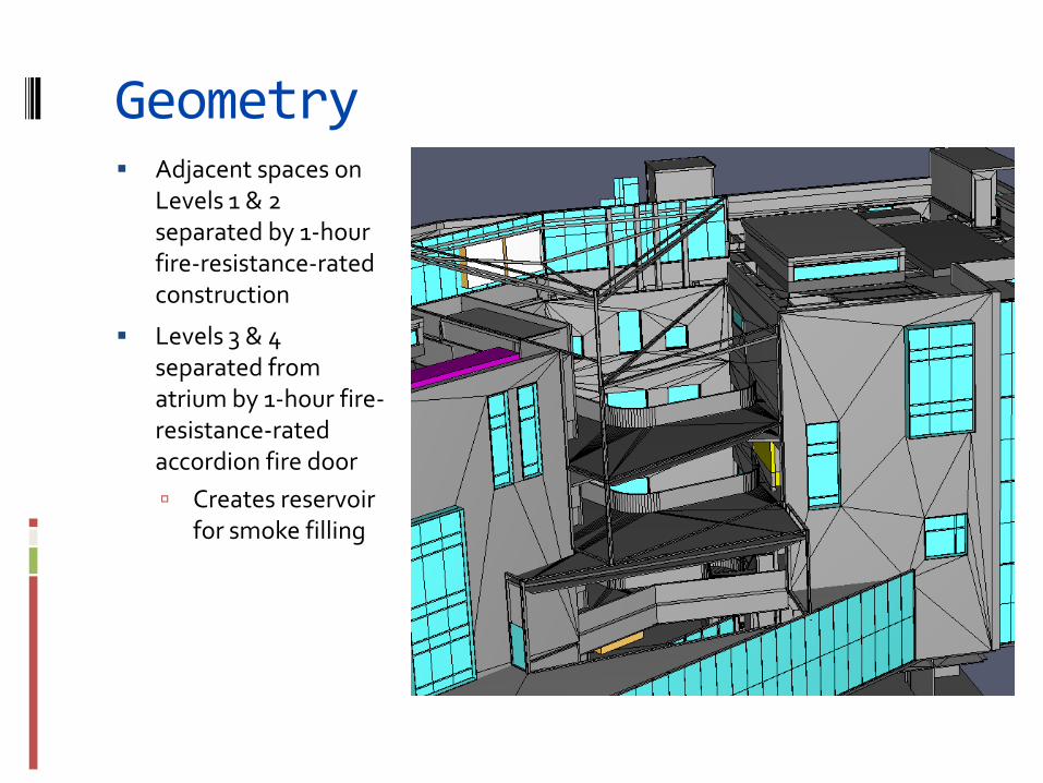
Geometry Adjacent spaces on
Levels 1 & 2 separated by 1-hour fire-resistance-rated construction
Levels 3 & 4 separated from atrium by 1-hour fire-resistance-rated accordion fire door
Creates reservoir for smoke filling
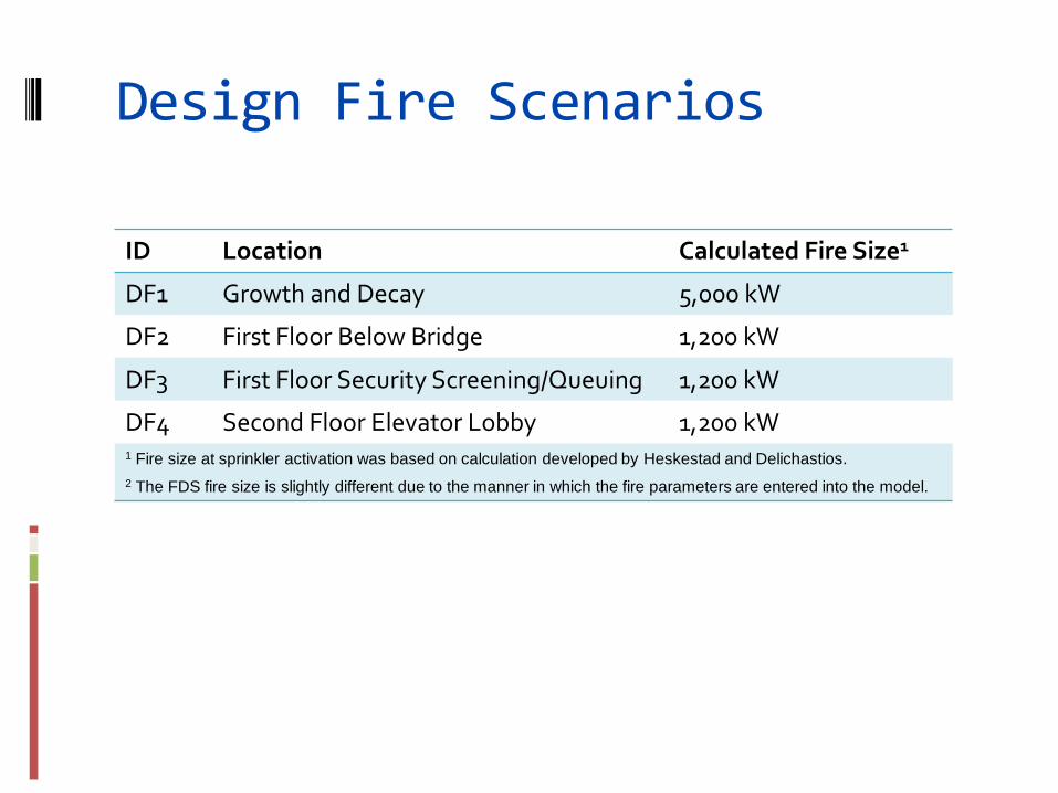
Design Fire Scenarios
ID Location Calculated Fire Size1
DF1 Growth and Decay 5,000 kW
DF2 First Floor Below Bridge 1,200 kW
DF3 First Floor Security Screening/Queuing 1,200 kW
DF4 Second Floor Elevator Lobby 1,200 kW 1 Fire size at sprinkler activation was based on calculation developed by Heskestad and Delichastios. 2 The FDS fire size is slightly different due to the manner in which the fire parameters are entered into the model.
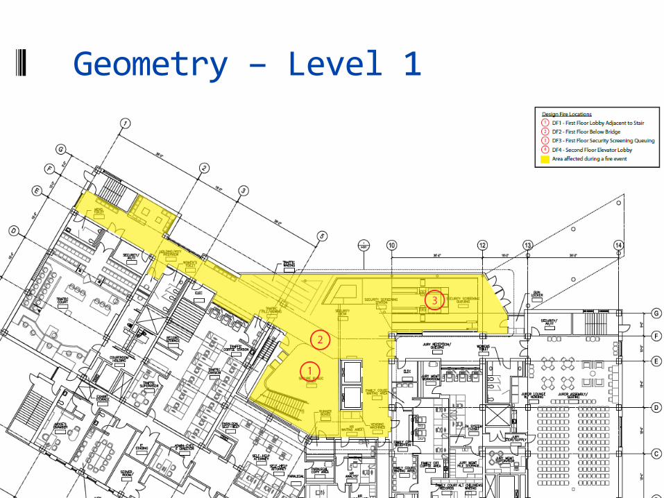
Geometry – Level 1
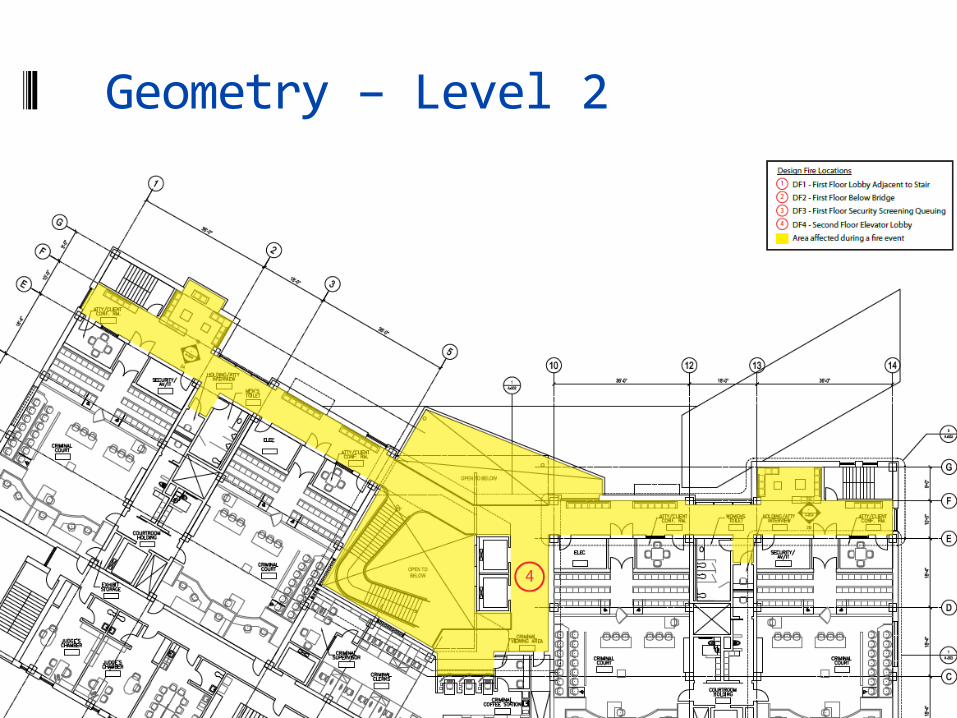
Geometry – Level 2
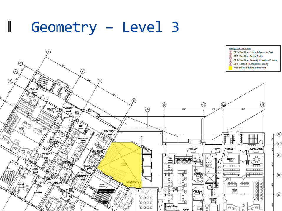
Geometry – Level 3
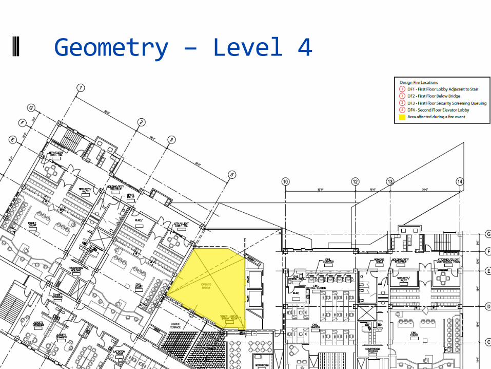
Geometry – Level 4
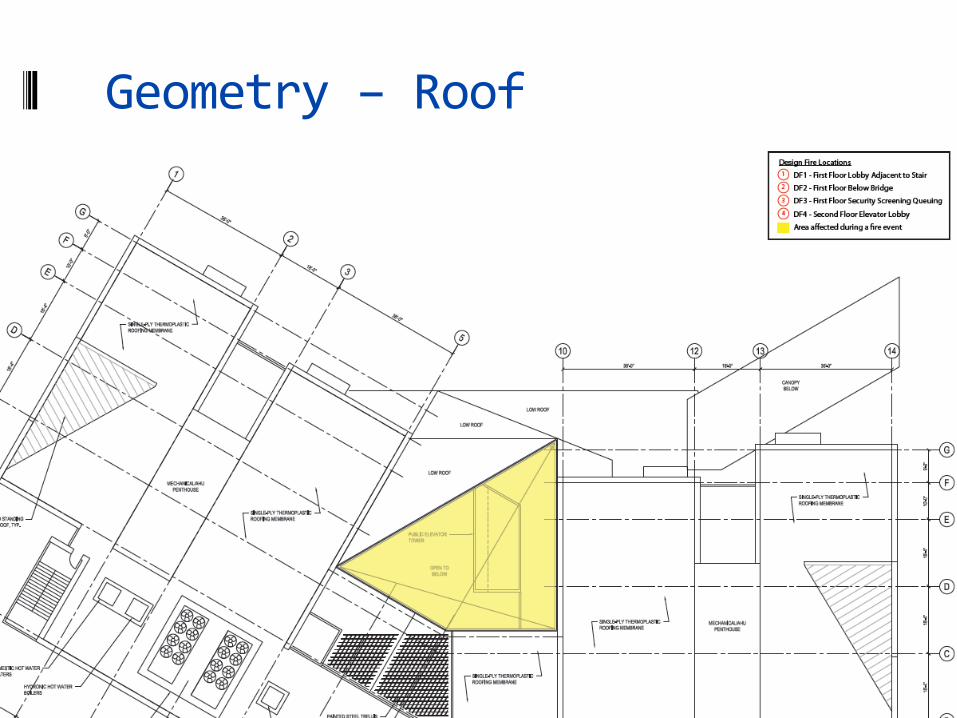
Geometry – Roof
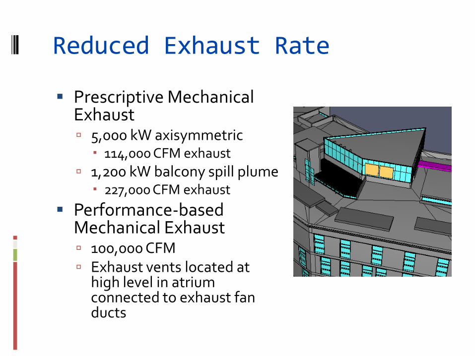
Reduced Exhaust Rate
Prescriptive Mechanical Exhaust 5,000 kW axisymmetric 114,000 CFM exhaust
1,200 kW balcony spill plume 227,000 CFM exhaust
Performance-based Mechanical Exhaust 100,000 CFM Exhaust vents located at
high level in atrium connected to exhaust fan ducts

Natural Make-up Openings Automatic doors and windows
L1 Main entrance clear area: 111 square feet L1 West window clear area: 26.5 square feet L2 East window clear area: 26.5 square feet L2 West window clear area: 26.5 square feet
Velocity through openings: ≤ 525 FPM
West Face View East Face View
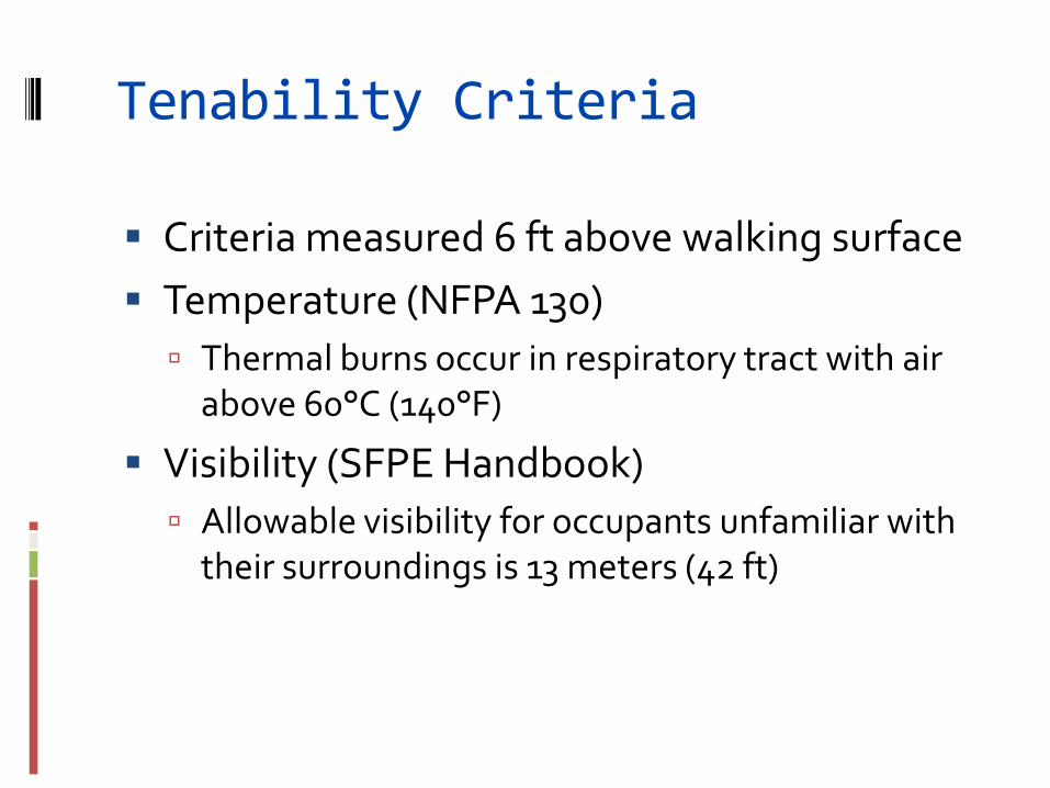
Tenability Criteria
Criteria measured 6 ft above walking surface
Temperature (NFPA 130)
Thermal burns occur in respiratory tract with air above 60°C (140°F)
Visibility (SFPE Handbook)
Allowable visibility for occupants unfamiliar with their surroundings is 13 meters (42 ft)
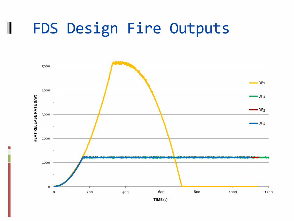
FDS Design Fire Outputs
0
1000
2000
3000
4000
5000
0 200 400 600 800 1000 1200
HE
AT
RE
LE
AS
E R
AT
E (
kW
)
TIME (s)
DF1
DF2
DF3
DF4
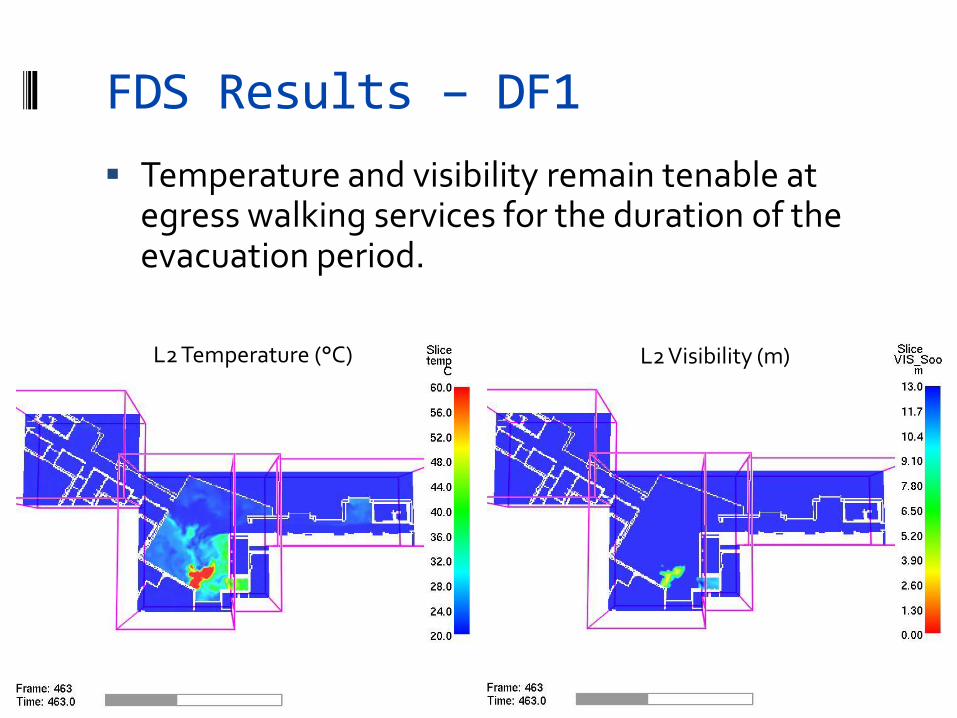
FDS Results – DF1
Temperature and visibility remain tenable at egress walking services for the duration of the evacuation period.
L2 Temperature (°C) L2 Visibility (m)
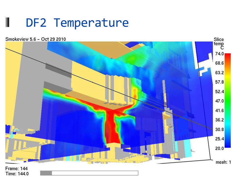
DF2 Temperature
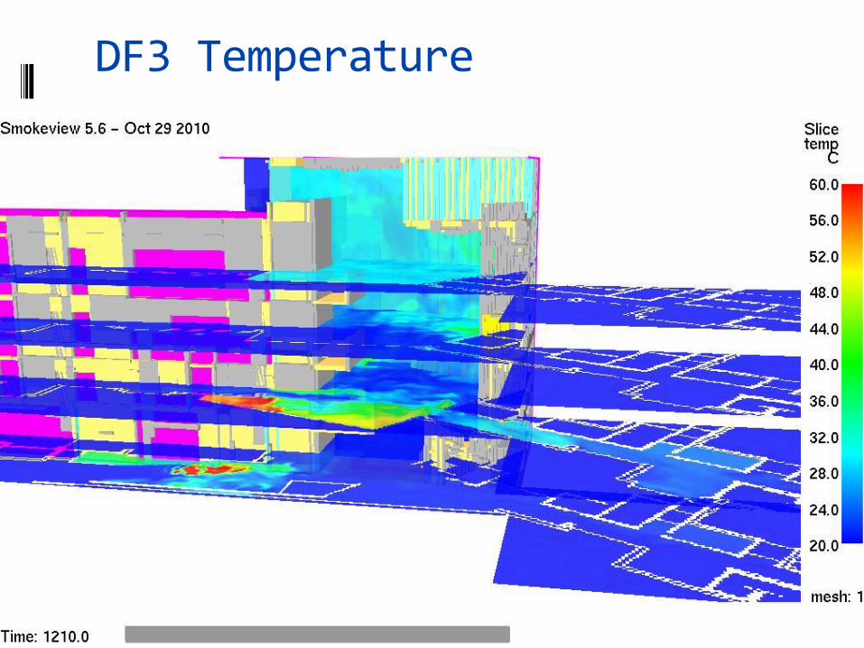
DF3 Temperature
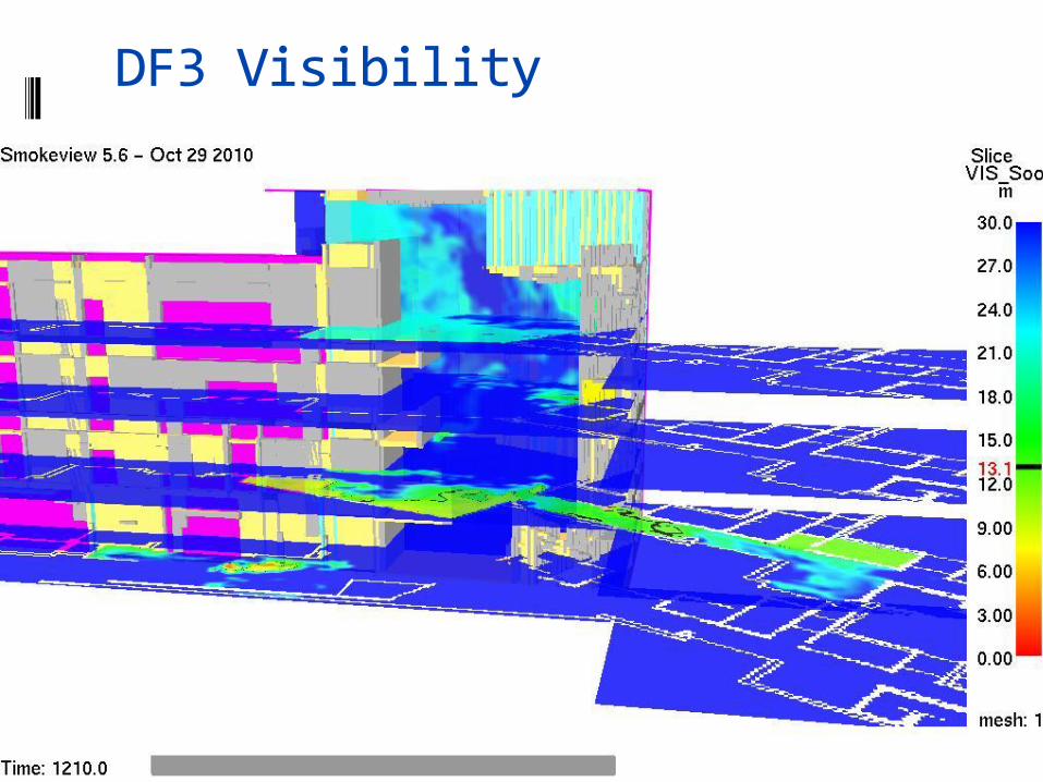
DF3 Visibility
•Performance based egress analysis
• RSET = 17 minutes
• ASET ≥ 20 minutes
•Performance based smoke control analysis
• 100,000 CFM mechanical exhaust
• Natural make-up openings
• 1-hour fire-resistance-rated accordion fire door
• 20 minutes of tenable conditions (ASET)
Results
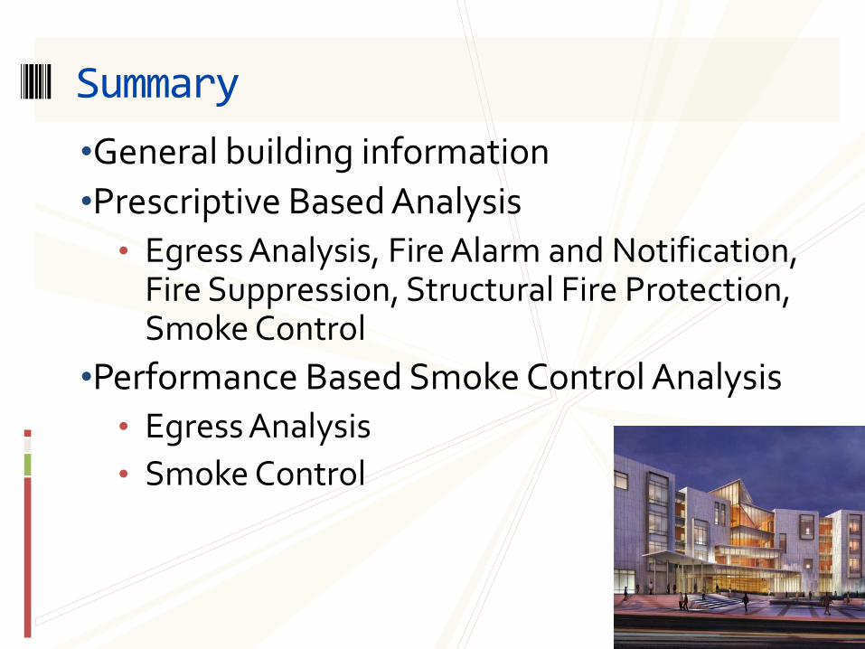
•General building information
•Prescriptive Based Analysis
• Egress Analysis, Fire Alarm and Notification, Fire Suppression, Structural Fire Protection, Smoke Control
•Performance Based Smoke Control Analysis
• Egress Analysis
• Smoke Control
Summary