fichatecnica ptp31
TRANSCRIPT
TI00384P/00/EN/14.11
71154777
Technical Information
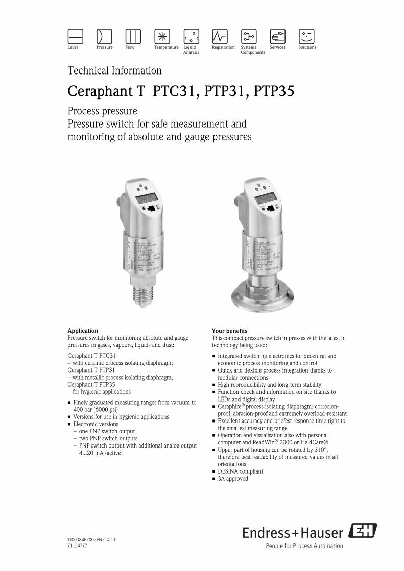
Ceraphant T PTC31, PTP31, PTP35
Process pressure
Pressure switch for safe measurement and
monitoring of absolute and gauge pressures
Application
Pressure switch for monitoring absolute and gauge
pressures in gases, vapours, liquids and dust:
Ceraphant T PTC31
− with ceramic process isolating diaphragm;
Ceraphant T PTP31
− with metallic process isolating diaphragm;
Ceraphant T PTP35
- for hygienic applications
• Finely graduated measuring ranges from vacuum to
400 bar (6000 psi)
• Versions for use in hygienic applications
• Electronic versions
– one PNP switch output
– two PNP switch outputs
– PNP switch output with additional analog output
4...20 mA (active)
Your benefits
This compact pressure switch impresses with the latest in
technology being used:
• Integrated switching electronics for decentral and
economic process monitoring and control
• Quick and flexible process integration thanks to
modular connections
• High reproducibility and long-term stability
• Function check and information on site thanks to
LEDs and digital display
• Ceraphire® process isolating diaphragm: corrosion-
proof, abrasion-proof and extremely overload-resistant
• Excellent accuracy and briefest response time right to
the smallest measuring range
• Operation and visualisation also with personal
computer and ReadWin® 2000 or FieldCare®
• Upper part of housing can be rotated by 310°,
therefore best readability of measured values in all
orientations
• DESINA compliant
• 3A approved

Ceraphant T
2 Endress+Hauser
Table of contents
Function and system design. . . . . . . . . . . . . . . . . . . . . 3
Device selection . . . . . . . . . . . . . . . . . . . . . . . . . . . . . . . . . . . . . . 3
Measuring principle . . . . . . . . . . . . . . . . . . . . . . . . . . . . . . . . . . . 3
Measuring system . . . . . . . . . . . . . . . . . . . . . . . . . . . . . . . . . . . . . 4
Input . . . . . . . . . . . . . . . . . . . . . . . . . . . . . . . . . . . . . . 4
Measured variable . . . . . . . . . . . . . . . . . . . . . . . . . . . . . . . . . . . . 4
Measuring range . . . . . . . . . . . . . . . . . . . . . . . . . . . . . . . . . . . . . . 4
Output . . . . . . . . . . . . . . . . . . . . . . . . . . . . . . . . . . . . . 4
Output signal . . . . . . . . . . . . . . . . . . . . . . . . . . . . . . . . . . . . . . . 4
Range of adjustment . . . . . . . . . . . . . . . . . . . . . . . . . . . . . . . . . . . 5
Switching capacity . . . . . . . . . . . . . . . . . . . . . . . . . . . . . . . . . . . . 5
Inductive load . . . . . . . . . . . . . . . . . . . . . . . . . . . . . . . . . . . . . . . 5
Signal on alarm . . . . . . . . . . . . . . . . . . . . . . . . . . . . . . . . . . . . . . 5
Load . . . . . . . . . . . . . . . . . . . . . . . . . . . . . . . . . . . . . . . . . . . . . . 5
Power supply. . . . . . . . . . . . . . . . . . . . . . . . . . . . . . . . 6
Electrical connection . . . . . . . . . . . . . . . . . . . . . . . . . . . . . . . . . . 6
Supply voltage . . . . . . . . . . . . . . . . . . . . . . . . . . . . . . . . . . . . . . . 7
Current consumption . . . . . . . . . . . . . . . . . . . . . . . . . . . . . . . . . . 7
Power supply failure . . . . . . . . . . . . . . . . . . . . . . . . . . . . . . . . . . . 7
Performance characteristics. . . . . . . . . . . . . . . . . . . . . 8
Reference operating conditions . . . . . . . . . . . . . . . . . . . . . . . . . . . 8
Switch output . . . . . . . . . . . . . . . . . . . . . . . . . . . . . . . . . . . . . . . 8
Analog output . . . . . . . . . . . . . . . . . . . . . . . . . . . . . . . . . . . . . . . 8
Influences of air pressure changes . . . . . . . . . . . . . . . . . . . . . . . . . 8
Long-term drift . . . . . . . . . . . . . . . . . . . . . . . . . . . . . . . . . . . . . . . 8
Long-term reliability . . . . . . . . . . . . . . . . . . . . . . . . . . . . . . . . . . . 8
Thermal change . . . . . . . . . . . . . . . . . . . . . . . . . . . . . . . . . . . . . . 8
Operating conditions (installation) . . . . . . . . . . . . . . . 9
Installation instructions . . . . . . . . . . . . . . . . . . . . . . . . . . . . . . . . . 9
Operating conditions (environment) . . . . . . . . . . . . . . 9
Ambient temperature range . . . . . . . . . . . . . . . . . . . . . . . . . . . . . 9
Storage temperature . . . . . . . . . . . . . . . . . . . . . . . . . . . . . . . . . . . 9
Degree of protection . . . . . . . . . . . . . . . . . . . . . . . . . . . . . . . . . . . 9
Shock resistance . . . . . . . . . . . . . . . . . . . . . . . . . . . . . . . . . . . . . . 9
Vibration resistance . . . . . . . . . . . . . . . . . . . . . . . . . . . . . . . . . . . 9
Electromagnetic
compatibility . . . . . . . . . . . . . . . . . . . . . . . . . . . . . . . . . . . . . . . . 9
Operating conditions (Process) . . . . . . . . . . . . . . . . . 10
Medium temperature range . . . . . . . . . . . . . . . . . . . . . . . . . . . . 10
Limiting medium pressure range . . . . . . . . . . . . . . . . . . . . . . . . . 10
Pressure specifications . . . . . . . . . . . . . . . . . . . . . . . . . . . . . . . . 10
Mechanical construction . . . . . . . . . . . . . . . . . . . . . . 11
Design, dimensions . . . . . . . . . . . . . . . . . . . . . . . . . . . . . . . . . . 11
Process connection PTC31 Sensor module with ceramic process
isolating diaphragm . . . . . . . . . . . . . . . . . . . . . . . . . . . . . . . . . . 12
Process connection PTP Sensor module with metallic process isolating
diaphragm . . . . . . . . . . . . . . . . . . . . . . . . . . . . . . . . . . . . . . . . . 13
Weight . . . . . . . . . . . . . . . . . . . . . . . . . . . . . . . . . . . . . . . . . . . . 15
Material (not wetted) . . . . . . . . . . . . . . . . . . . . . . . . . . . . . . . . . 16
Material (wetted) . . . . . . . . . . . . . . . . . . . . . . . . . . . . . . . . . . . . 17
Human interface . . . . . . . . . . . . . . . . . . . . . . . . . . . . 18
Operating elements . . . . . . . . . . . . . . . . . . . . . . . . . . . . . . . . . . 18
On-site operation . . . . . . . . . . . . . . . . . . . . . . . . . . . . . . . . . . . . 18
Operation with PC . . . . . . . . . . . . . . . . . . . . . . . . . . . . . . . . . . . 21
Certificates and approvals . . . . . . . . . . . . . . . . . . . . . 22
CE mark . . . . . . . . . . . . . . . . . . . . . . . . . . . . . . . . . . . . . . . . . . 22
UL listing . . . . . . . . . . . . . . . . . . . . . . . . . . . . . . . . . . . . . . . . . . 22
Pressure Equipment Directive (PED) . . . . . . . . . . . . . . . . . . . . . 22
Suitability for hygenic processes . . . . . . . . . . . . . . . . . . . . . . . . . 22
Standards and guidelines . . . . . . . . . . . . . . . . . . . . . . . . . . . . . . 22
Ordering Information. . . . . . . . . . . . . . . . . . . . . . . . . 23
Ceraphant T PTC31 . . . . . . . . . . . . . . . . . . . . . . . . . . . . . . . . . . 23
Ceraphant T PTP31 . . . . . . . . . . . . . . . . . . . . . . . . . . . . . . . . . . 25
Ceraphant T PTP35 . . . . . . . . . . . . . . . . . . . . . . . . . . . . . . . . . . 27
Questionnaire on customer-
specific configuration . . . . . . . . . . . . . . . . . . . . . . . . . . . . . . . . . 28
Accessories . . . . . . . . . . . . . . . . . . . . . . . . . . . . . . . . 29
Welding boss
− with sealing taper . . . . . . . . . . . . . . . . . . . . . . . . . . . . . . . . . . 29
Welding boss
− with sealing surface . . . . . . . . . . . . . . . . . . . . . . . . . . . . . . . . 29
Thread adapter . . . . . . . . . . . . . . . . . . . . . . . . . . . . . . . . . . . . . 29
Clamp adapter . . . . . . . . . . . . . . . . . . . . . . . . . . . . . . . . . . . . . . 29
Hygiene adapter . . . . . . . . . . . . . . . . . . . . . . . . . . . . . . . . . . . . . 30
Plug-in jack . . . . . . . . . . . . . . . . . . . . . . . . . . . . . . . . . . . . . . . . 30
Connecting cable . . . . . . . . . . . . . . . . . . . . . . . . . . . . . . . . . . . . 30
Configuration kit . . . . . . . . . . . . . . . . . . . . . . . . . . . . . . . . . . . . 31
Power supply RNB130 . . . . . . . . . . . . . . . . . . . . . . . . . . . . . . . . 31
Documentation . . . . . . . . . . . . . . . . . . . . . . . . . . . . . 31
Field of Activities . . . . . . . . . . . . . . . . . . . . . . . . . . . . . . . . . . . . 31
Technical Information . . . . . . . . . . . . . . . . . . . . . . . . . . . . . . . . 31
Operating instructions . . . . . . . . . . . . . . . . . . . . . . . . . . . . . . . . 31

Ceraphant T
Endress+Hauser 3
Function and system design
Device selection
Measuring principle Ceraphant T PTC31
The process pressure acts on the ceramic process isolating diaphragm and the pressure-dependent change in
capacitance of the ceramic sensor is measured. A microprocessor evaluates the signal and switches the output
or outputs the corresponding measured value.
The ceramic sensor is a dry sensor i.e. no fill fluid is needed for pressure transmission. This means that the
sensor can fully support a vacuum. Extremely high durability, on a par with the material Alloy, is achieved
through the use of the highly pure material Ceraphire® as a ceramic.
Ceraphant T PTP31 and PTP35
The process pressure acting upon the metallic process isolating diaphragm of the sensor is transmitted to a
resistance bridge via a fluid. The change in the output voltage of the bridge is proportional to the pressure and
can be measured directly.
Ceraphant T -
product family
PTC31 PTP31 PTP35
P01-PTC31xxx-14-xx-xx-xx-001
P01-PTP31xxx-14-xx-xx-xx-001
P01-PTP35xxx-14-xx-xx-xx-001
Measuring cell With capacitive measuring cell
and ceramic process isolating
diaphragm (Ceraphire®)
With piezoresistive measuring
cell and metallic process
isolating diaphragm
With piezoresistive measuring
cell and metallic process
isolating diaphragm for
hygienic applications
Field of application Measurement and monitoring of
absolute and gauge pressures
Measurement and monitoring
of absolute and gauge pressures
Measurement and monitoring
of absolute and gauge pressures
in hygienic processes
Process connection Thread
− G ¼ female
− G ¼A and G ½A
− G ½A, hole 11.4 mm
− M12x1,5
− 7/16-20 UNF
− ¼ FNPT and ½ MNPT
Thread
− G ¼ female
− G ¼A and G ½A
− G ½A, hole 11.4 mm
− M12x1,5
− 7/16-20 UNF
− ¼ FNPT and ½ MNPT
− G ½A flush mounted
Hygiene
− Clamp ½" - 2"
− G 1A
− Varivent F, N
− DIN 11851
− APV inline
− SMS 1½"
Measuring range 0 to 0.1 bar (1.5 psi)
to
0 to 40 bar (600 psi)
0 to 1 bar (15 psi)
to
0 to 400 bar (6000 psi)
0 to 1 bar (15 psi)
to
0 to 40 bar (600 psi)
Process
temperature
−40°C to +100°C
(−40°F to +212°F)
−40°C to +100°C
(−40°F to +212°F)
−40°C to +100°C
(−40 °F to +212 °F)
135°C (275°F) max. 1 hour

Ceraphant T
4 Endress+Hauser
Measuring system
P01-PTx3xxxx-14-xx-xx-xx-001
A: 1x PNP switch output
B: 2x PNP switch output
C: PNP switch output with additional analog output 4...20 mA (active).
➀ Transmitter power supply unit
➁ Load (e.g. programmable logic controller, process control system, relay)
Input
Measured variable The measured variable for the pressure switch can be selected as either gauge pressure or absolute pressure.
Measuring range Measuring ranges up to 400 bar (6000 psi), see "Ordering information" section.
Output
Output signal DC voltage version: Positive voltage signal (rate depends on power supply voltage) at electronics switch output
(PNP). Short-circuit proof version.
• 1x PNP switch output
• 2x PNP switch output
• PNP switch output with additional active analog output 4...20 mA.
The analog output continuously represents the measuring range configured or specified by the sensor.
➩➩➩
p
pp
1
2
2
2
A B
C
11

Ceraphant T
Endress+Hauser 5
Range of adjustment • Switch output:
Switch point (SP): 0.5...100 % in increments of 0.1 % (min. 1 mbar * (0.015 psi)) of the upper range limit
(URL)
Switch-back point (RSP): 0...99.5 % in increments of 0.1 % (min. 1 mbar * (0.015 psi)) of the upper range
limit (URL)
Min. distance between SP and RSP: 0.5% URL
* measuring ranges with negative gauge pressure up to 4 bar (60 psi) in increments of min. 10 mbar (0.15
psi)
• Analog output (if available):
Lower range value (LRV) and upper range value (URV) can be set anywhere within the sensor range (LRL -
URL). Turn down of the analog output up to 4:1 of the upper range limit (URL).
• Damping: can be set anywhere between 0...40 s in increments of 0.1 s
• Factory setting (if no customer-specific settings have been ordered):
Switch point SP 1: 45 %; Switch-back point RSP 1: 44.5 %
Switch point SP 2: 55 %; Switch-back point RSP 2: 54.5 %
Analog output: LRV 0 %; URV 100 %
LRL = Lower Range Limit / URL = Upper Range Limit
LRV = Lower Range Value / URV = Upper Range Value
Switching capacity DC voltage version:
• Switch status ON: Ia ≤250 mA, switch status OFF: Ia ≤1 mA
• Switching cycles: >10,000,000
• Voltage drop PNP: ≤2 V
• Overload resistance: Automatic load check of switching current;
max. capacitance load: 14 μF at max. supply voltage (without resistive load)
max. period length: 0.5 s; min. ton: 40 μs
Periodic disconnection from a protective circuit in event of overcurrent (f = 2 Hz) and indication of
"Warning"
Inductive load To prevent electrical interference, only operate an inductive load (relays, contactors, solenoid valves) when
directly connected to a protective circuit (free-wheeling diode or capacitor).
Signal on alarm • Analog output
≤ 3,6 mA / last current value / ≥21,0 mA adjustable (if setting ≥21.0 mA the output is ≥21.5 mA)
• Switch outputs: In safe state (switch normally open)
Load Max. (USupply −6.5 V) / 0.22 A (analog output)

Ceraphant T
6 Endress+Hauser
Power supply
Electrical connection Connector and cable connection
P01-PTx3xxxx-04-xx-xx-xx-001
A: M12x1 connector;
B: M16x1.5 or ½ NPT valve plug
C: cable, 5 m (16.4 ft) long, 5-core
➀ reference pressure supply
Device connection
• DC voltage version with M12x1 connector
P01-PTx3xxxx-04-xx-xx-xx-002
A1: 1x PNP switch output
A2: PNP switch outputs R1 and ➀ (R2)
A2’: PNP switch outputs R1 and ➀ (diagnosis/break contact with adjustment "DESINA")
A3: PNP switch output with additional analog output
A3’: PNP switch output with additional analog output (PIN assignment with "DESINA" setting)
• DC voltage version with M16x1.5 or ½ NPT valve plug
P01-PTx3xxxx-04-xx-xx-xx-003
B: 1x PNP switch output
➀
A B C
M16x1.5 / ½ NPT 5 m (16.4 ft)M12x1
4...20mA4...20mA
L–
L–L–
L–
L+
L+L+
L+
2
22
2 1
11
1
3
33
3 4
44
4R1 ➀
Diag.R1
R1
A1 A2A2’
A3’A3
1
3
L–
L+
2R
B

Ceraphant T
Endress+Hauser 7
• DC voltage version with cable
P01-PTx3xxxx-04-xx-xx-xx-004
C1: 1x PNP switch output
C2: 2x PNP switch output
C2’: PNP switch outputs R1 and ➀ (diagnosis/break contact with adjustment "DESINA")
C3: PNP switch output with additional analog output
C3’: PNP switch output with additional analog output (assignment with "DESINA" setting)
Cable specification: all three connection versions 5-core; 4 x 0.2 mm2(AWG25), PE 0.75 mm2(AWG18)
– Core colours: BN = brown, BK = black, WH = white, BU = blue, GNYE = green/yellow
Supply voltage • DC voltage version
12...30 V DC
Current consumption Without load < 60 mA, with reverse polarity protection
Power supply failure • Behaviour in case of overvoltage (>30 V)
The device works continuously without any damage up to 34 V DC.
The specific properties are no longer guaranteed if the supply voltage is exceeded.
No damage is caused to the device in case of a short-term overvoltage up to 1 kV (as per EN 6100-4-5)
• Behaviour in case of undervoltage
If the supply voltage drops below the minimum value, the device switches off (status as if not supplied with
power = switch open).
L–
L– L–
L–
L+
L+ L+
L+
R1
R1 Diag.4...20mA 4...20mA
R1 ➀
WH WH
WH
BU
GNYE GNYE
GNYE GNYEBU BU
BU
BN
BN BN
BN
BK
BK BK
BK
C1 C2C2’
C3 C3’
Ceraphant T
8 Endress+Hauser
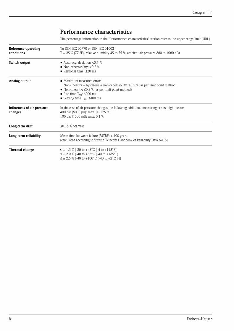
Performance characteristicsThe percentage information in the "Performance characteristics" section refer to the upper range limit (URL).
Reference operating
conditions
To DIN IEC 60770 or DIN IEC 61003
T = 25 C (77 °F), relative humidity 45 to 75 %, ambient air pressure 860 to 1060 hPa
Switch output • Accuracy: deviation <0.5 %
• Non-repeatability: <0.2 %
• Response time: ≤20 ms
Analog output • Maximum measured error:
Non-linearity + hysteresis + non-repeatability: ≤0.5 % (as per limit point method)
• Non-linearity: ≤0.2 % (as per limit point method)
• Rise time T90: ≤200 ms
• Settling time T99: ≤400 ms
Influences of air pressure
changes
In the case of air pressure changes the following additional measuring errors might occur:
400 bar (6000 psi): max. 0.0275 %
100 bar (1500 psi): max. 0.1 %
Long-term drift ≤0.15 % per year
Long-term reliability Mean time between failure (MTBF) > 100 years
(calculated according to "British Telecom Handbook of Reliability Data No. 5)
Thermal change ≤ ± 1.5 % (-20 to +45°C (-4 to +113°F))
≤ ± 2.0 % (-40 to +85°C (-40 to +185°F)
≤ ± 2.5 % (-40 to +100°C (-40 to +212°F))

Ceraphant T
Endress+Hauser 9
Operating conditions (installation)
Installation instructions • Any orientation
• Any position-dependent zero shift can be corrected. Offset: ±20 % URL
• Housing can be rotated up to 310 °
Oxygen applications
Oxygen and other gases can react explosively to oils, grease and plastics, such that, among other things, the
following precautions must be taken:
– All components of the system, such as measuring devices, must be cleaned in accordance with BAM
requirements (DIN 19247). (BAM = Federal Institute for Materials Research and Testing).
– Depending on the materials used, a certain maximum temperature and a maximum pressure must not be
exceeded in oxygen applications. The maximum temperature Tmax for oxygen applications is 60°C (140°F).
The devices suitable for gaseous oxygen applications are listed in the following table, indicated by pmax.
Operating conditions (environment)
Ambient temperature range -40 to +85°C (-40 to +185°F), briefly up to +100°C (212°F)
Storage temperature -40 to +85°C (-40 to 185°F)
Degree of protection • M12x1 connector
Gauge pressure sensors IP 65; Absolute pressure sensors: IP 66
• M16x1.5 or ½ NPT valve plug
IP 65
• Cable: IP 66
For applications where the device is installed outdoor or cleaned from outside we recommend the use of a
protection cap.
Shock resistance 50 g to DIN IEC 68-2-27 (11 ms)
Vibration resistance 20 g to DIN IEC 68-2-6 (10-2000Hz)
Electromagnetic
compatibility
• Interference emission as per EN 61326, class B electrical equipment
• Interference immunity as per EN 61326, appendix A (industrial use)
Order code for devices cleaned for oxygen applications pmax for oxygen applications
PTC31 – * * * ** * ** 6 *,
for devices with sensors, nominal value < 10 bar (150 psi)
Overpressure limit (OPL) of sensor1)
1) → See Page 23 ff "Ordering information", feature 80 "Sensor seal".
PTC31 – * * * ** * ** 6 *,
for devices with sensors, nominal value ≥10 bar (150 psi)
30 bar (450 psi)

Ceraphant T
10 Endress+Hauser
Operating conditions (Process)
Medium temperature range • PTC31, PTP31: −40°C...+100°C (-40°F to +212°F)
• PTP35: −40°C...+100°C (-40°F to +212°F), +135°C (+275°F) for max. 1 hour
Please also note the temperature limits of the seal used (see page 12: Material)
Extreme jumps in temperature can result in temporary errors. Temperature compensation takes effect after
several minutes. Internal temperature compensation is faster the smaler the temperature jump and the longer
the time interval
Limiting medium pressure
range
• For overload resistance see "Ordering information" section
• Vacuum resistance
For ceramic sensor with nominal value >100 mbar (1.5 psi): 0 mbarabs (0 psi)
For ceramic sensor 100 mbar (1.5 psi): 700 mbarabs (10.5 psi)
For metal sensor: 10 mbarabs (0.15 psi)
Pressure specifications The maximum pressure for the measuring device is dependent on the weakest element with regard to pressure,
see the following sections "Ordering information: Measuring range" and "Mechanical construction"
The MWP (maximum working pressure) is specified on the nameplate. This value refers to a reference
temperature of +20 °C (-68°F) and may be applied to the device for an unlimited time.
The test pressure (Over Pressure Limit OPL) corresponds to 1.5 times the MWP and may be applied for a
limited time only in order to avoid lasting damage.

Ceraphant T
Endress+Hauser 11
Mechanical construction
Design, dimensions Dimensions
P01-PTx3xxxx-06-xx-xx-xx-001
M12x1 connector as per IEC 60947-5-2
M16x1.5 or ½ NPT valve plug as per DIN 43650A/ISO 4400
Cable 5 m (16 ft) long, cable outer diameter 7.7 mm (0.3 in); cores 4 x 0.2 mm2(AWG 24), PE 0.75 mm2(AWG 18)
reference pressure hose with outer diameter 2.5 mm (0.1 in)
➀ Across flats AF 27 mm(for 400 bar (6000 psi) sensor AF 32 mm)
A = height dimension of process connections − see next diagrams
Process connection
P01-PTx3xxxx-06-xx-xx-xx-006
PTC31: sensor module ➀ with process connection.
PTP31/35: sensor module ➁ with M24x1.5 adapter thread for adapters with process connection.
Adapter (mounted onto sensor module at the factory, 400 bar (6000 psi) thread adapter welded onto sensor module)
➂ Adapter with thread connection
➃ Adapter with clamp connection (except ½" clamp)
➄ Adapter with hygienic connection (except G 1A)
ø42.3 (1.67)
10
5(4
.13
)
52
(2.0
5)
52
(2.0
5)
11
(0.4
3)
39 (1.54)
36 (1.42)52 (2.05)
24 (0.94)24 (0.94)
A AA
ø38.5 (1.52)
65 (2.56)
mm (inch)
24 (0.94)
M16x1.5 / ½ NPTM12x1 5 m (16,4 ft)
1
M24x1.5
PTC31 PTP31, PTP35
2
3 4 5
1

Ceraphant T
12 Endress+Hauser
Process connection PTC31
Sensor module with ceramic
process isolating diaphragm
P01-PTx3xxxx-14-xx-xx-xx-003
PTC31; sensor module with process connection
➀ with internal thread
➁ with external thread
"Seal" detail: ➂ Ceraphire ceramic sensor, ➃ moulded seal, in contact with process, ➄ sensor module
Dimension A: see the following dimension drawings (dimension with *)
Thread connections
P01-PTx3xxxx-06-xx-xx-xx-002
Process connection versions (see also "Ordering information" section)
AC: thread ISO 288, G¼ (female)
AD: thread ISO 288, G¼A
AE: thread ISO 288, G½A
AF: thread ISO 288, G½A, bore 11 mm (0.43 in)
BA: Thread DIN 13, M12x1.5
CA: thread 7/16-20 UNF (SAE)
DA: thread ANSI ¼ FNPT
DD: thread ANSI ½ MNPT
A
1 23
4
5
PTC31
M12x1.5 1/4NPT
Ø3 (0.12)
Ø6 (0.24)
G1/4
7/16-20UNF
G1/2
17
(0.6
7)
23
.1*
(0.9
1)
3(0
.12
)
Ø17.5 (0.69)
17
(0.6
7)
20
*(0
.79
)
Ø11.4(0.45)
1/2NPT
25
.15
*(0
.99
)
.4(0.84)Ø21
Ø3 (0.12)
G1/4A
12
*(0
.47
)
AC AD AE AF
BA DA DDCA
11
(0.4
3)
11
(0.4
3)
11
(0.4
3)
11
(0.4
3)
11
(0.4
3)
11
(0.4
3)
11
(0.4
3)
11
(0.4
3)
Ø11.4(0.45)
Ø11.4(0.45)
G1/2
Ø29.9 (1.18)
SW
27
(AF
27m
m)
mm (inch)

Ceraphant T
Endress+Hauser 13
Process connection PTP
Sensor module with metallic
process isolating diaphragm
P01-PTx3xxxx-14-xx-xx-xx-002
➀ Sensor module with adapter thread for adapters with thread connection
➁ Sensor module with adapter thread for adapters with clamp or hygiene connection
➂ Sensor module with clamp or hygiene connection (only versions DA, BA, BB)
"Seal" detail: ➃ sensor module, ➄ Standard O-ring, in contact with process, ➅ adapter
Dimension A: see the following dimension drawing (dimension with *). For 400 bar (6000 psi) sensor see also Page 12.
Process connection PTP31 Thread connections
P01-PTx3xxxx-06-xx-xx-xx-020
Process connection versions: sensor module with adapter (see also "Ordering information" section)
AC: thread ISO 228, G¼ (female)
AD: thread ISO 228, G¼A
AE: thread ISO 228, G½A
AF: thread ISO 228, G½A, bore 11 mm (0.43 in)
BA: Thread DIN 13, M12x1.5
CA: thread 7/16-20 UNF (SAE)
DA: thread ANSI ¼ FNPT
DD: thread ANSI ½ MNPT
4
4
5
56
6
A
A
A
2 31 PTP31 PTP35PTP35
Ø17.3 (0.7)
1/2"NPT
Ø11.4 (0.45)
25.1
5(0
.99)
DA
CA
Ø23 (0.9)
15
.5(0
.61
)
1/4 NPT
Ø11.4 (0.45)
Ø26 (1.02)
34
(1.3
4)
15
.5(0
.61
)
7/16-20 UNF
BA
DD
Ø23 (0.9)
15
.5(0
.61
)
M12x1.5
34
(1.3
4)
34
(1.3
4)
47
(1.8
5)
Ø17.5 (0.69)
Ø23 (0.9)
G1/4
3(0
.12)
3(0
.12)
Ø6 (0.24)
Ø3 (0.12)
Ø17.5 (0.69)
G1/2A
20
(0.7
9)
Ø11.4 (0.45)
G1/4A
Ø3 (0.12)
AC AD AE
AF
34
(1.3
4)
45
(1.7
7)
15
.5(0
.61
)
12
(0.4
7)
34
(1.3
4)
42
(1.6
5)
G1/2A
20
(0.7
9)
mm (inch)

Ceraphant T
14 Endress+Hauser
Process connection PTP31 Flush-mounted nozzle
P01-PMP131xx-06-09-xx-xx-002
Process connection PTP31; Version AG
AG: Thread ISO 228 G ½, seal DIN 3852 flush-mounted
m: Dimensions for tapped hole G ½ as per DIN 3852-11 form X
Process connection PTP35 Hygiene connections
P01-PTx3xxxx-06-xx-xx-xx-004
Process connection versions
BA: thread ISO 228 G1A, metal taper seal
BB: thread ISO 228 G1A, O-ring seat seal
Process connection versions (sensor module with adapter)
LB: Varivent F pipe DN 25-32, PN 40
LL: Varivent N pipe DN 40-162, PN 40
PH: DIN 11851, DN 40, PN 40 (including slotted nut)
PL: DIN 11851, DN 50, PN 25 (including slotted nut)
HL: APV inline, DN 50, PN 40, (B = bores 6 x Ø8.6 + 2 x M8 thread)
KL: SMS 1½ PN 25, 316L, 3A
See also "Ordering information" section
27 (1.06)
14
(0.5
)
2.5
(0.1
)
22
(0.9
)
G ½14
(14
.5)
G ½
ø26 (1)
17
(0.6
7)
11
(0.4
3)
1 mm (inch)AG
Ø50 (1.97)
Ø66 (2.60)
Ø61,5 (2.42)Ø82 (3.23)Ø100 (3.94)
LB
HLLL
BA BB
Ø68 (2.68)
Ø84 (3.31)
18
*(0
.71
)
Ø51 (2.01)
Ø68 (2.68)
PL
17
*(0
.67
)
Ø39 (1.54)
Ø56 (2.20)
PH
17
*(0
.67
)
18
*(0
.71
)
19
*(0
.75
)
Ø30(1.18)
G1"
Ø41(1.61)
SW41AF41mm
SW41AF41mm
Ø29 (1.14)
G1"
Ø41 (1.61)
B
11
.5(0
.45
)
11
.5(0
.45
)
25
.3(1
.00
)
32
.5(1
.28
)KL
Ø54,85 (2.16)
SW32AF32mm
17
(0.6
7)
mm (inch)
SW32AF32mm
SW32AF32mm
Ceraphant T
Endress+Hauser 15
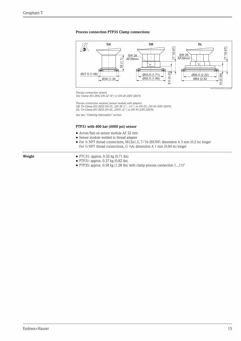
Process connection PTP35 Clamp connections
P01-PTx3xxxx-06-xx-xx-xx-005
Process connection version
DA: Clamp ISO 2852 DN 22 (¾") or DN 20 (DIN 32676)
Process connection versions (sensor module with adapter)
DB: Tri-Clamp ISO 2852 DN 25...DN 38 (1"...1½" ) or DN 25...DN 40 (DIN 32676)
DL: Tri-Clamp ISO 2852 DN 40...DN51 (2" ) or DN 50 (DIN 32676)
See also "Ordering information" section
PTP31 with 400 bar (6000 psi) sensor
• Across flats on sensor module AF 32 mm
• Sensor module welded to thread adapter
• For ¼ NPT thread connections, M12x1.5, 7/16-20UNF: dimension A 5 mm (0.2 in) longer
For ½ NPT thread connections, G ½A: dimension A 1 mm (0.04 in) longer
Weight • PTC31: approx. 0.32 kg (0.71 lbs)
• PTP31: approx. 0.37 kg (0.82 lbs)
• PTP35: approx. 0.58 kg (1.28 lbs) with clamp process connection 1...1½"
Ø27.5 (1.08)
Ø34 (1.34
8.5
(0.3
3)
17
*(0.6
7)
DB
Ø56.5 (2.22)
Ø64 (2.52
DL
10
(0.3
9)
17
*(0.6
7)
SW 28AF28mm
28
(1.1
)
DA
Ø43.5 (1.71)
Ø50.5 (1.99)
SW 28AF28mm

Ceraphant T
16 Endress+Hauser
Material (not wetted) Housing
P01-PTx3xxxx-06-xx-xx-xx-012
Front view, left-hand side view
Filling oil
Filling oil for PTP31 and PTP35: synthetic oil, FDA number 21-CFR 172.882
M16x1.5 / ½ NPTM12x1
5 m (16,4 ft)
1
2
3 4
6
7
8
9
10
11
12
135
18
19
15
14
16
17
20
Item
number
Component part Material
1 Housing F25 AISI 316 L (1.4404) with electropolished surface Ra ≤ 0,8 μm (31,5 μin)
2 Seal between display and
housing
Closed-cell acrylate adhesive
3 Dispay PC-FR LEXAN 943A
4 Keys PC-FR LEXAN
5 CDI cover TPE SANTOPRENE 151-60
6 Sensor jack 1.4435
7 O ring FKM
8 M-12 jack 316L (1.4404/1.4435)
9 Inner jack PA; contacts CuZn nickel-plated
10 Valve jack 316L (1.4404/1.4435)
11 Seal jack NBR
12 ISO plug PA
13 Screw V2A
14 Jack PBT-FR
15 O ring EPDM
16 Cable PUR/UL 94 V0
17 Cable gland PA
18 M16 jack 316L (1.4404/1.4435)
19 Coupling nut SMS 11861 1.4307
20 Coupling nut DRD 1.4301
Ceraphant T
Endress+Hauser 17
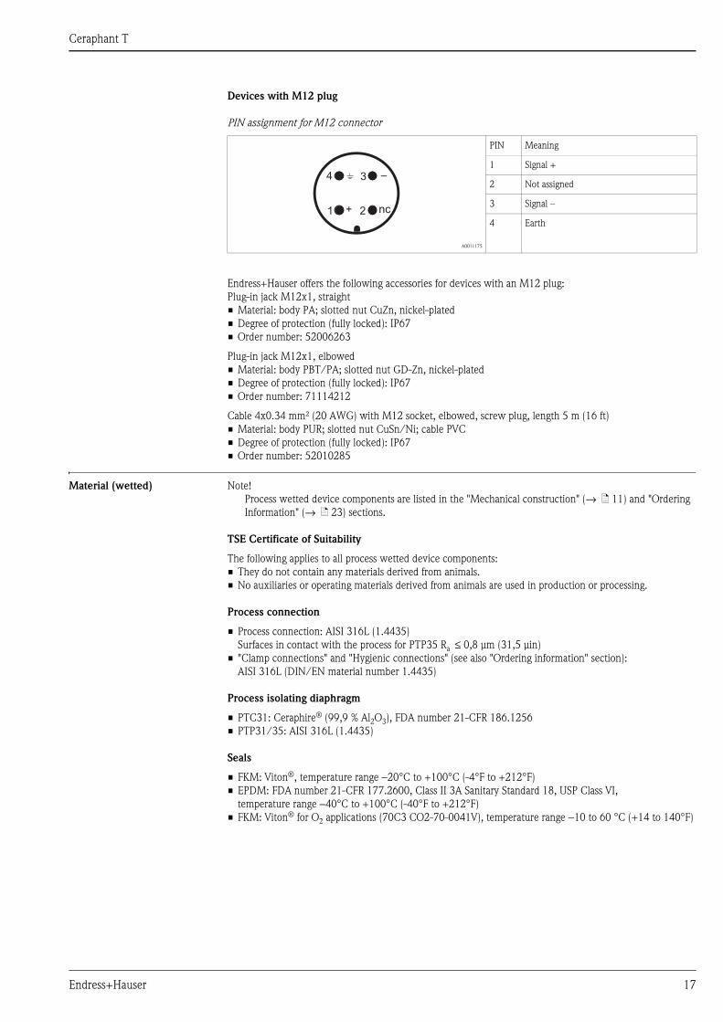
Devices with M12 plug
PIN assignment for M12 connector
Endress+Hauser offers the following accessories for devices with an M12 plug:
Plug-in jack M12x1, straight
• Material: body PA; slotted nut CuZn, nickel-plated
• Degree of protection (fully locked): IP67
• Order number: 52006263
Plug-in jack M12x1, elbowed
• Material: body PBT/PA; slotted nut GD-Zn, nickel-plated
• Degree of protection (fully locked): IP67
• Order number: 71114212
Cable 4x0.34 mm² (20 AWG) with M12 socket, elbowed, screw plug, length 5 m (16 ft)
• Material: body PUR; slotted nut CuSn/Ni; cable PVC
• Degree of protection (fully locked): IP67
• Order number: 52010285
Material (wetted) Note!
Process wetted device components are listed in the "Mechanical construction" (→ ä 11) and "Ordering
Information" (→ ä 23) sections.
TSE Certificate of Suitability
The following applies to all process wetted device components:
• They do not contain any materials derived from animals.
• No auxiliaries or operating materials derived from animals are used in production or processing.
Process connection
• Process connection: AISI 316L (1.4435)
Surfaces in contact with the process for PTP35 Ra ≤ 0,8 μm (31,5 μin)
• "Clamp connections" and "Hygienic connections" (see also "Ordering information" section):
AISI 316L (DIN/EN material number 1.4435)
Process isolating diaphragm
• PTC31: Ceraphire® (99,9 % Al2O3), FDA number 21-CFR 186.1256
• PTP31/35: AISI 316L (1.4435)
Seals
• FKM: Viton®, temperature range −20°C to +100°C (-4°F to +212°F)
• EPDM: FDA number 21-CFR 177.2600, Class II 3A Sanitary Standard 18, USP Class VI,
temperature range −40°C to +100°C (-40°F to +212°F)
• FKM: Viton® for O2 applications (70C3 CO2-70-0041V), temperature range −10 to 60 °C (+14 to 140°F)
A0011175
PIN Meaning
1 Signal +
2 Not assigned
3 Signal –
4 Earth
21
34
+
–
nc

Ceraphant T
18 Endress+Hauser
Human interface
Operating elements Position and meaning of display and operating elements.
P01-PTx3xxxx-19-xx-xx-en-003
The background illumination of the digital display indicates the status of the device:
white = ok; red = error
On-site operation Menu-guided operation using operating keys.
Operating key
Communications jackfor personal computer
Digital display
Yellow LEDs for switching statesLED on = switch closedLED off = switch open
LED for statusGreen = okRed = error
Red/green-blinking= warning
E
22.07 bar
Function group Operating options
BASE
(basic functions)
Selection of unit: bar, psi, kPa/MPa
Offset: ±20 % URL
Damping display value, output signal: anywhere between 0...40 s (in increments of 0.1 s)
Display:
− Display of measured value or configured switch point
− Rotation of display by 180°
− Switching off display
Behaviour according to DESINA:
The PIN assignment of the M12 connector is in accordance with the guidelines of DESINA
(DESINA = distributed and standardised installation technology for machine tools and
manufacturing systems)
OUT
(Configuration of
1st output)
Output function:
− Hysteresis function or window function
− NC contact or NO contact
(see next diagram)
− Analog output 4...20 mA
Switch point:
− Input value
− Acceptance of applied value
Switch point anywhere between 0.5...100 % URL
(in increments of 0.1 %, min. 0.001 bar (0.015 psi))
Switch-back point:
− Input value
− Acceptance of applied value
Switch-back point anywhere between 0...99.5 % URL
(in increments of 0.1 %, min. 0.001 bar (0.015 psi))
Switch output delay: anywhere between 0...99 s (in increments of 0.1 s)

Ceraphant T
Endress+Hauser 19
OUT 2
(Configuration of
2nd output,
only for corresponding
electronics version)
Output function:
− Hysteresis function or window function
− NC contact or NO contact
(see next diagram)
− Analog output 4...20 mA
Switch point 2:
− Input value
− Acceptance of applied value
Switch point anywhere between 0.5...100 % URL
(in increments of 0.1 %, min. 0.001 bar (0.015 psi))
Switch-back point 2:
− Input value
− Acceptance of applied value
Switch-back value anywhere between 0...99.5 % URL
(in increments of 0.1 %, min. 0.001 bar (0.015 psi))
Switch output delay: anywhere between 0...99 s (in increments of 0.1 s)
4-20
(configuration of
analog output,
only for corresponding
electronic version)
Lower range value (LRV) and upper range value (URV) of analog output:
− Input value
− Acceptance of applied value
Anywhere within sensor range (in increments of 0.1 %); turn down up to 4 : 1
Setting of error current: choice of ≤3.6 mA / ≥21.0 mA / last current value
SERV
(service functions)
Resetting of all settings to factory settings
Static Revision Counter (configuration counter; increases by one with every change in
configuration)
Locking by means of freely selectable code
Display of last error to occur
Simulation of switch output and analog output
Display of max. measured pressure value
Display of min. measured pressure value
Note Measuring ranges with negative gauge pressure up to 4 bar (60 psi)
in increments of min. 0.01 mbar (0.15 psi)
Function group Operating options
Ceraphant T
20 Endress+Hauser
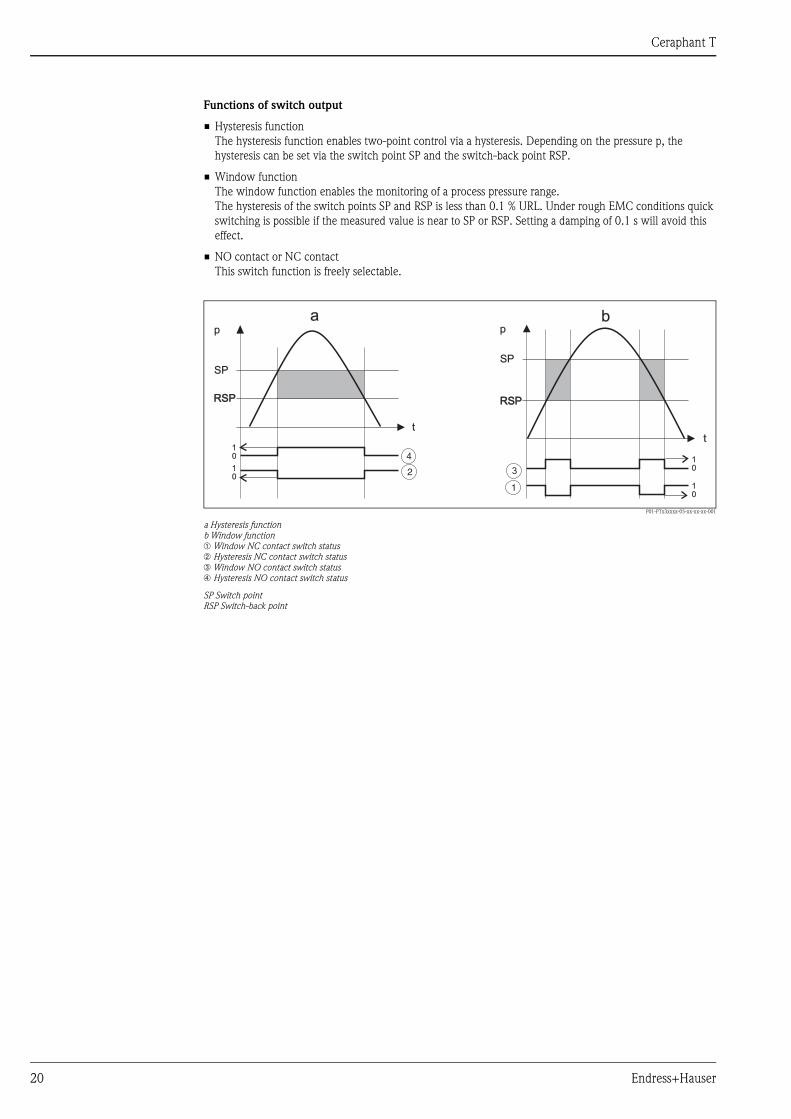
Functions of switch output
• Hysteresis function
The hysteresis function enables two-point control via a hysteresis. Depending on the pressure p, the
hysteresis can be set via the switch point SP and the switch-back point RSP.
• Window function
The window function enables the monitoring of a process pressure range.
The hysteresis of the switch points SP and RSP is less than 0.1 % URL. Under rough EMC conditions quick
switching is possible if the measured value is near to SP or RSP. Setting a damping of 0.1 s will avoid this
effect.
• NO contact or NC contact
This switch function is freely selectable.
P01-PTx3xxxx-05-xx-xx-xx-001
a Hysteresis function
b Window function
➀ Window NC contact switch status
➁ Hysteresis NC contact switch status
➂ Window NO contact switch status
➃ Hysteresis NO contact switch status
SP Switch point
RSP Switch-back point
tt
1
2 3
4
p
a bp
SPSP
RSPRSPRSPRSP
0
00
0
1
11
1
Ceraphant T
Endress+Hauser 21
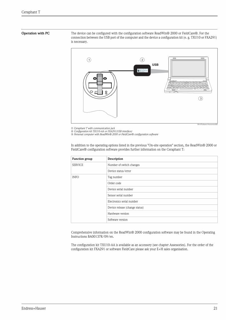
Operation with PC The device can be configured with the configuration software ReadWin® 2000 or FieldCare®. For the
connection between the USB port of the computer and the device a configuration kit (e. g. TXU10 or FXA291)
is necessary.
P01-PTx3xxxx-19-xx-xx-xx-002
➀ Ceraphant T with communication jack
➁ Configuration kit TXU10-AA or FXA291(USB interface)
➂ Personal computer with ReadWin® 2000 or FieldCare® configuration software
In addition to the operating options listed in the previous "On-site operation" section, the ReadWin® 2000 or
FieldCare® configuration software provides further information on the Ceraphant T:
Comprehensive information on the ReadWin® 2000 configuration software may be found in the Operating
Instructions BA00137R/09/en.
The configuration kit TXU10-AA is available as an accessory (see chapter Assessories). For the order of the
configuration kit FXA291 or software FieldCare please ask your E+H sales organisation.
USB
1 2
3
Function group Description
SERVICE Number of switch changes
Device status/error
INFO Tag number
Order code
Device serial number
Sensor serial number
Electronics serial number
Device release (change status)
Hardware version
Software version
Ceraphant T
22 Endress+Hauser
Certificates and approvals
CE mark The device meets the legal requirements of the EC directives. Endress+Hauser confirms that the device has
been successfully tested by applying the CE mark.
UL listing The device was examined by Underwriters Laboratories Inc. USA (UL) in accordance with the standards UL
61010B-1 and CSA C22.2 No. 1010.1-92 and listed under the number E225237 UL for Canada and the USA.
Pressure Equipment Directive
(PED)
This measuring device corresponds to Article 3 (3) of the EC Directive 97/23/EC (Pressure Equipment
Directive) and has been designed and manufactured according to good engineering practice.
Suitability for hygenic
processes
Standards and guidelines DIN EN 60770 (IEC 60770):
Transmitters for use in industrial-process control systems
Part 1: Methods for performance evaluation.
DIN EN 61003-1, publication date:1993-12
Industrial-process control systems - Instruments with analog inputs and two- or multi-state outputs - Part 1:
Methods of evaluating the performance.
DIN 16086
Electrical pressure measuring instruments; pressure sensors, pressure transmitters, pressure measuring
instruments;
concepts, specifications on data sheets
IEC 60529
Degrees of protection provided by enclosures (IP code).
EN 61326
Electrical equipment for measurement, control and laboratory use - EMC requirements.
IEC 61010
Safety requirements for electrical equipment for measurement, control and laboratory use.
EN 61000-4-5
Electromagnetic compatibility (EMC) -
Part 4: Testing and measurement techniques; Section 5: Surge immunity test
The Ceraphant T PTP35 is suitable for the employment in hygenic processes.
An overview of permitted process connections on page 14 and 15.
Many versions meet the requirements of 3A-Sanitary Standard No. 74.
Note!
The gap-free connections can be cleaned without residue using the
usual cleaning methods.74 -74 -

Ceraphant T
Endress+Hauser 23
Ordering Information
Ceraphant T PTC31 This overview does not mark options which are mutually exclusive.
10 Certificate
A For non-hazardous areas
20 Electrical connection
1 M 12x1 connector: IP 65; with sensors for gauge pressure and absolute pressure: IP 66
2 M16x1.5 valve plug, ISO 4400: IP 65
3 ½NPT valve plug, ISO 4400: IP 65
4 5 m (16.4 ft) cable: IP 66
30 Electronics, output signal
A 12...30V DC, PNP switch, 3-wire
B 12...30V DC, 2 PNP switch, 4-wire
C 12...30 V DC, PNP switch + 4...20mA, 4-wire
40 Display
1 With digital display
50 Sensor
Gauge pressure Max. working pressure MWP Overload OPL
1C 0...0.1bar / 0...10 kPa 2.7 bar 4 bar
1F 0...0.4 bar / 0...40 kPa 5.3 bar 8 bar
1H 0...1 bar / 0...100 kPa 6.7 bar 10 bar
1M 0...4 bar / 0...400 kPa 16.7 bar 25 bar
1P 0...10 bar / 0...1000 kPa 26.7 bar 40 bar
1S 0...40 bar / 0...4000 kPa 40 bar 60 bar
Negative gauge pressure Max. working pressure MWP Overload OPL
5C -0.1...0.1 bar / -10...10 kPa 2.7 bar 4 bar
5F -0.4...0.4 bar / -40...40 kPa 5.3 bar 8 bar
5H -1...1 bar / -100...100 kPa 6.7 bar 10 bar
5M -1...4 bar / -100...400 kPa 16.7 bar 25 bar
5P -1...10 bar / -100...1000 kPa 26.7 bar 40 bar
Absolute pressure Max. working pressure MWP Overload OPL
2F 0...0.4 bar / 0...40 kPa 5.3 bar 8 bar
2H 0...1 bar / 0...100 kPa 6.7 bar 10 bar
2M 0...4 bar / 0...400 kPa 16.7 bar 25 bar
2P 0...10 bar / 0...1000 kPa 26.7 bar 40 bar
2S 0...40 bar / 0...4000 kPa 40 bar 60 bar
60 Configuration and unit
1 Sensor range: bar Calibration in sensor range
2 Sensor range: kPa/MPa Calibration in sensor range
3 Sensor range: psi Calibration in sensor range
S Switch output 1, see additional specification Calibration in sensor range
T Switch output 1 + 2, see additional specification Calibration in sensor range
U Switch and analog output, see additional specification Calibration in sensor range
V Switch output 1, switch output 2 DESINA, see add. spec. Calibration in sensor range
W Analog output, switch output DESINA, see add. spec. Calibration in sensor range
70 Process connection, material
AC Thread ISO 288, G¼ (female), 316L
AD Thread ISO 228, G¼A, 316L
AE Thread ISO 228, G½A, 316L
AF Thread ISO 228, G½A, bore 11.4 mm, 316L
BA Thread DIN 13, M 12x1.5, 316L
CA Thread 7/16-20 UNF (SAE), 316L
DA Thread ANSI ¼ FNPT, 316L
DD Thread ANSI ½ MNPT, 316L
80 Sensor seal (in contact with process)
1 FKM Viton sensor seal
4 EPDM sensor seal
6 FKM Viton sensor seal, cleaned for O2 service
90 Additional equipment
A Without additional equipment
B Final inspection report
C 3.1 (process connection), inspection certificate to EN 10204

Ceraphant T
24 Endress+Hauser
D Final inspection report + 3.1 (process connection), inspect. certificate to EN 10204
995 Marking:
1 Tagging (TAG), see additional spec.
PTC31 order code
90 Additional equipment

Ceraphant T
Endress+Hauser 25
Ceraphant T PTP31 This overview does not mark options which are mutually exclusive.
10 Certificate
A For non-hazardous areas
20 Electrical connection
1 M 12x1 connector: IP 65; with sensors for gauge pressure and absolute pressure: IP 66
2 M16x1.5 valve plug, ISO 4400: IP 65
3 ½NPT valve plug, ISO 4400: IP 65
4 5 m (16.4 ft) cable: IP 66
30 Electronics, output signal
A 12...30V DC, PNP switch, 3-wire
B 12...30V DC, 2 PNP switch, 4-wire
C 12...30 V DC, PNP switch + 4...20mA, 4-wire
40 Display
1 With digital display
50 Sensor
Gauge pressure Max. working pressure MWP Overload OPL
3H 0...1 bar / 0...100 kPa 2.7 bar 4 bar
3M 0...4 bar / 0...400 kPa 10.7 bar 16 bar
3P 0...10 bar / 0...1000 kPa 26.7 bar 40 bar
3S 0...40 bar / 0...4000 kPa 100 bar 160 bar
3U 0...100 bar / 0...10 MPa 100 bar 160 bar
3Z 0...400 bar / 0...40 MPa 400 bar 600 bar
Negative gauge pressure Max. working pressure MWP Overload OPL
7H -1...1 bar / -100...100 kPa 2.7 bar 4 bar
7M -1...4 bar / -100...400 kPa 10.7 bar 16 bar
7P -1...10 bar / -100...1000 kPa 26.7 bar 40 bar
Absolute pressure Max. working pressure MWP Overload OPL
4H 0...1 bar / 0...100 kPa 2.7 bar 4 bar
4M 0...4 bar / 0...400 kPa 10.7 bar 16 bar
4P 0...10 bar / 0...1000 kPa 26.7 bar 40 bar
4S 0...40 bar / 0...4000 kPa 100 bar 160 bar
4U 0...100 bar / 0...10 MPa 100 bar 160 bar
4Z 0...400 bar / 0...40 MPa 400 bar 600 bar
60 Configuration and unit
1 Sensor range: bar Calibration in sensor range
2 Sensor range: kPa/MPa Calibration in sensor range
3 Sensor range: psi Calibration in sensor range
S Switch output 1, see additional specification Calibration in sensor range
T Switch output 1 + 2, see additional specification Calibration in sensor range
U Switch and analog output, see additional specification Calibration in sensor range
V Switch output 1, switch output 2 DESINA, see add. spec. Calibration in sensor range
W Analog output, switch output DESINA, see add. spec. Calibration in sensor range
70 Process connection, material
AC Thread ISO 288, G¼ (female), 316L
AD Thread ISO 228, G¼A, 316L
AE Thread ISO 228, G½A, 316L
AF Thread ISO 228, G½A, bore 11.4 mm, 316L
AG Thread ISO 228, G½A, seal DIN 3852, 316L, flush-mounted
BA Thread DIN 13, M 12x1.5, 316L
CA Thread 7/16-20 UNF (SAE), 316L
DA Thread ANSI ¼FNPT, 316L
DD Thread ANSI ½MNPT, 316L
80 Seal, filling fluid
1 O-ring FKM Viton, synthetic oil
4 O-ring EPDM, synthetic oil
7 Welded, synthetic oil (only for 400 bar sensor)
90 Additional equipment
A Without additional equipment
B Final inspection report
C 3.1 (process connection), inspection certificate to EN 10204
D Final inspection report + 3.1 (process connection), inspect. certificate to EN 10204

Ceraphant T
26 Endress+Hauser
995 Marking:
1 Tagging (TAG), see additional spec.
PTP31 order code

Ceraphant T
Endress+Hauser 27
Ceraphant T PTP35 This overview does not mark options which are mutually exclusive.
10 Certificate
A For non-hazardous areas
20 Electrical connection
1 M 12x1 connector: IP 65; with sensors for gauge pressure and absolute pressure: IP 66
2 M16x1.5 valve plug, ISO 4400: IP 65
3 ½NPT valve plug, ISO 4400: IP 65
4 5 m (16.4 ft) cable: IP 66
30 Electronics, output signal
A 12...30V DC, PNP switch, 3-wire
B 12...30V DC, 2 PNP switch, 4-wire
C 12...30 V DC, PNP switch + 4...20mA, 4-wire
40 Display
1 With digital display
50 Sensor
Gauge pressure Max. working pressure MWP Overload OPL
3H 0...1 bar / 0...100 kPa 2.7 bar 4 bar
3M 0...4 bar / 0...400 kPa 10.7 bar 16 bar
3P 0...10 bar / 0...1000 kPa 26.7 bar 40 bar
3S 0...40 bar / 0...4000 kPa 100 bar 160 bar
Negative gauge pressure Max. working pressure MWP Overload OPL
7H -1...1 bar / -100...100 kPa 2.7 bar 4 bar
7M -1...4 bar / -100...400 kPa 10.7 bar 16 bar
7P -1...10 bar / -100...1000 kPa 26.7 bar 40 bar
Absolute pressure Max. working pressure MWP Overload OPL
4H 0...1 bar / 0...100 kPa 2.7 bar 4 bar
4M 0...4 bar / 0...400 kPa 10.7 bar 16 bar
4P 0...10 bar / 0...1000 kPa 26.7 bar 40 bar
4S 0...40 bar / 0...4000 kPa 100 bar 160 bar
60 Configuration and unit
1 Sensor range: bar Calibration in sensor range
2 Sensor range: kPa/MPa Calibration in sensor range
3 Sensor range: psi Calibration in sensor range
S Switch output 1, see additional specification Calibration in sensor range
T Switch output 1 + 2, see additional specification Calibration in sensor range
U Switch and analog output, see additional specification Calibration in sensor range
V Switch output 1, switch output 2 DESINA, see add. spec. Calibration in sensor range
W Analog output, switch output DESINA, see add. spec. Calibration in sensor range
70 Process connection, material
Clamp connections
DA ISO 2852 DN12-22 (¾"), 316L, 3A, EHEDG 2), DIN32676, DN10-20
DB ISO 2852 DN25-38 (1...1½"), 316L, 3A, EHEDG 2), DIN32676, DN25-40
DL ISO 2852 DN40-51 (2"), 316L, 3A, EHEDG 2), DIN32676, DN50
Hygienic connections
BA Thread ISO 228 G1A, metal taper seal, 316L,
flush-mounted for sleeve 52005087
BB Thread ISO 228 G1A, O-ring seat seal, 316L,
flush-mounted for sleeve 52001051
KL SMS 1½" PN 25, 316L, 3A 1), EHEDG 2)
1) Suitable fittings and seals must be used for hygienic design in accordance with 3A specifications.
2) Suitable fittings and seals must be used for hygienic design in accordance with EHEDG specifications.
LB Varivent F pipe DN 25-32, PN 40, 316L, 3A
LL Varivent N pipe DN4 0-162, PN 40, 316L, 3A
PH DIN 11851 DN 40 PN 40, slotted nut, 316L, 3A 1), EHEDG 2)
PL DIN 11851 DN 50 PN 25, slotted nut, 316L, 3A 1), EHEDG 2)
HL APV Inline DN 50 PN 40, 316L, EHEDG
80 Seal, filling fluid
4 O-ring EPDM, oil conform to FDA
8 Without O-ring, oil conform to FDA (only for process connections BA, BB, DA)

Ceraphant T
28 Endress+Hauser
Questionnaire on customer-
specific configuration
The Ceraphant T pressure switch can also be ordered with customised settings. For this purpose, please use
the questionnaire below. Information on the desired switch point (SP), switch-back point (RSP), lower range
value and upper range value always refer to the pressure unit selected. The possible range of adjustment is
indicated in the questionnaire in % of the upper range limit (URL). The bold-printed specifications are the
factory settings.
P01-PTx3xxxx-16-xx-xx-en-001
90 Additional equipment
A Without additional equipment
B Final inspection report
C 3.1.B process connection, inspection certificate to EN10204
D Final inspection report + 3.1 (process connection), inspect. certificate to EN10204
995 Marking:
1 Tagging (TAG), see additional spec.
PTP35 order code
Output 1 (Application 1)
Function: ( ) 1 = ( ) 3 =( ) 2 =
SP: Range of adjustment: 0,5...100 % URL (in increments of 0.1 %, min. 1 mbar *)
RSP: Range of adjustment: 0...99,5 % URL (in increments of 0.1 %, min. 1 mbar *)
* increments of min. 10 mbar with neg. gauge pressure up to 4 bar
( ) 4 =Window normally closed Window normally open
Hysteresis normally closed Hysteresis normally open
Min. difference SP – RSP: 0,5% URL
Output 2 (Application 2) (only if available)
Function:( ) 1 = ( ) 3 =( ) 2 =
SP: Range of adjustment: 0,5...100 % URL (in increments of 0.1 %, min. 1 mbar *)
RSP: Range of adjustment: 0...99,5 % URL (in increments of 0.1 %, min. 1 mbar *)
( ) 4 =Window normally closed Window normally open ( ) 5 = 4...20 mA (only if available)
Hysteresis normally closed Hysteresis normally open
* increments of min. 10 mbar with neg. gauge pressure up to 4 bar
Analogue output (only if output 2 = 4...20 mA output available)
Range low scale:
Range high scale:
Failure mode:
(only for 2 outputs): ( ) yes
Hint: See section “Devices Connection”
Range of adjustment: 0....100 % URL
Range of adjustment: 0....100 % URLTurn down up to 4 : 1
( ) 1 = 3.6 mA ( ) 3 = last current value≤ ≥( ) 2 = 21.0 mA
Connection conform to DESINA ( ) no
Questionnaire ustomer-specific setupfor Ceraphant PTC31, PTP31, PTP35 for c
Pressure unit ( ) bar ( ) kPa/MPa ( ) psi
TAG
(max. 2 x 18characters)

Ceraphant T
Endress+Hauser 29
Accessories
Welding boss
− with sealing taper
Welding boss
− with sealing surface
Thread adapter
Clamp adapter
• Welding boss for flush mounting process
connection G1 A with metallic sealing taper
(version BA for PTP35)
Material: AISI 316L
Order number: 52005087
• Optional with inspection certificate 3.1
Order number: 52010171
• Welding aid (Dummy) for welding the welding
boss without any problems, order number
52005087 or 52010171
Material: brass
Order number: 52005272
P01-Pxxxxxxx-00-xx-00-xx-001
ø50 (1,97)
30
(1.1
8)
27
.5(1
.08
)
mm(inch)
• Welding boss for flush mounting process
connection G1 A with sealing surface (version BB
for PTP35)
Material: AISI 316L
Order number: 52001051
• Seal (enclosed): silicone O-ring
FDA approved materials according to
21 CFR Part 177.1550/2600
• Optional with inspection certificate 3.1:
Order number: 52011896P01-PMP13xxx-00-xx-00-xx-002
ø60 (2.4)–0.4
24
.6(0
.97
)
29
.6(1
.2)
ø41 (1.6)
G1
mm (inch)
• PTP31: order numbers for thread adapter versions
Version AC: order no. 52023980
Version AD: order no. 52023981
Version AE: order no. 52023982
Version AF: order no. 52023983
Version BA: order no. 52023984
Version CA: order no. 52023985
Version DA: order no. 52023986
Version DD: order no. 52023987
See chapter "Process connection PTP31 Thread connections" → ä 13.
• PTP35: Order numbers for clamp adapter versions
Version DB: order no. 52023994
Version DL: order no. 52023995
Optional with inspection certificate 3.1:
Version DB: order no. 52024001
Version DL: order no. 52024002
See chapter "Process connection PTP35 Clamp connections" → ä 15.

Ceraphant T
30 Endress+Hauser
Hygiene adapter
Plug-in jack
Connecting cable
• PTP35: order numbers for hygiene adapter versions
Version KL: order no. 52026997
Version LB: order no. 52023996
Version LL: order no. 52023997
Version PH: order no. 52023999
Version PL: order no. 52023998
Version HL: order no. 52024000
Optional with inspection certificate 3.1:
Version KL: order no. 52026999
Version LB: order no. 52023996
Version LL: order no. 52024004
Version PH: order no. 52024006
Version PL: order no. 52024005
Version HL: order no. 52024007
See chapter "Process connection PTP35 Hygiene connections" → ä 14.
• M12x1 plug-in jack
Self-made connection to M12x1 plug
Materials: Body PA
Coupling nut: Cu Zn, brass, nickeled
Protection: IP 67 (fully locked)
Order number: 52006263P01-PMP13xxx-00-xx-00-xx-003
• M12x1 plug-in jack, elbowed
Self-made connection to M12x1 plug
Materials: Body PA
Coupling nut: GD-Zn, brass, nickeled
Protection: IP 67 (fully locked)
Order number: 51006327
P01-Pxxxxxxx-00-xx-00-xx-002
20
(0.8
)
41
(1.6
)
35 (1.4)
14.8 (0.6)mm (inch)
• Cable, 4 x 0.34 mm2 (AWG 21) with M12 socket,
elbowed, screw plug, length 5 m (16 ft), sprayed
cable
Materials: Body PUR
Coupling nut: Cu Zn/Ni, brass, nickeled
Cable: PVC
Protection: IP 67 (fully locked)
order number: 52010285
• Cable, 4 x 0.34 mm2 (AWG 21) with M12 socket,
with LED, elbowed, sprayed cable, length 5 m (16
ft), specially for hygiene applications
(For devices with switch output only)
Materials: Body: PVC
Coupling nut: 316L
Cable: PVC
Protection: IP 69K (fully locked)
Order number: 52018763
Display: gn: device operational;
ye1: switch status; ye 2: switch status 2
P01-PTx3xxxx-07-xx-xx-xx-001
ye2
ye1
gn
2
R R
2 (wh)1
1 (bn)
3 3 (bu)4
4 (bk)
L–
L+
Ceraphant T
Endress+Hauser 31
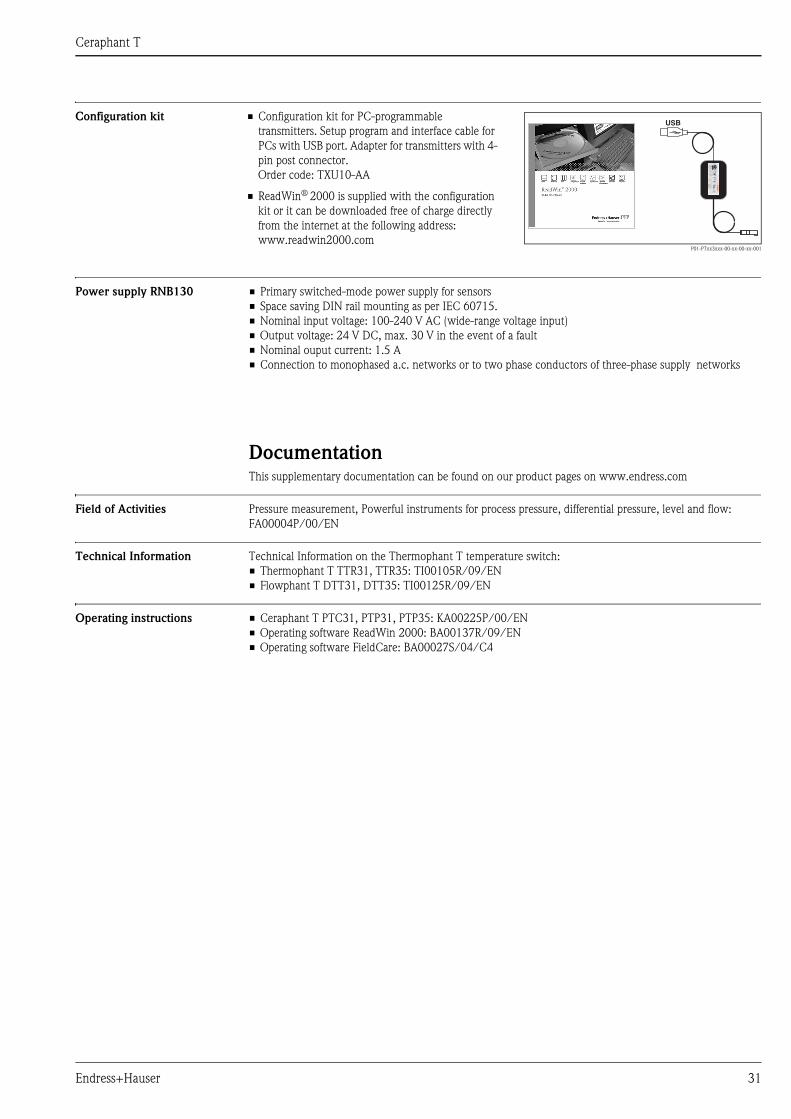
Configuration kit
Power supply RNB130 • Primary switched-mode power supply for sensors
• Space saving DIN rail mounting as per IEC 60715.
• Nominal input voltage: 100-240 V AC (wide-range voltage input)
• Output voltage: 24 V DC, max. 30 V in the event of a fault
• Nominal ouput current: 1.5 A
• Connection to monophased a.c. networks or to two phase conductors of three-phase supply networks
DocumentationThis supplementary documentation can be found on our product pages on www.endress.com
Field of Activities Pressure measurement, Powerful instruments for process pressure, differential pressure, level and flow:
FA00004P/00/EN
Technical Information Technical Information on the Thermophant T temperature switch:
• Thermophant T TTR31, TTR35: TI00105R/09/EN
• Flowphant T DTT31, DTT35: TI00125R/09/EN
Operating instructions • Ceraphant T PTC31, PTP31, PTP35: KA00225P/00/EN
• Operating software ReadWin 2000: BA00137R/09/EN
• Operating software FieldCare: BA00027S/04/C4
• Configuration kit for PC-programmable
transmitters. Setup program and interface cable for
PCs with USB port. Adapter for transmitters with 4-
pin post connector.
Order code: TXU10-AA
• ReadWin® 2000 is supplied with the configuration
kit or it can be downloaded free of charge directly
from the internet at the following address:
www.readwin2000.comP01-PTxx3xxx-00-xx-00-xx-001
Instruments International
Endress+HauserInstruments International AGKaegenstrasse 24153 ReinachSwitzerland
Tel.+41 61 715 81 00Fax+41 61 715 25 [email protected]
TI00384P/00/EN/14.11
71154777
FM+SGML 6.071154777