fibre laser nitriding of titanium and its alloy in open...
TRANSCRIPT

General rights Copyright and moral rights for the publications made accessible in the public portal are retained by the authors and/or other copyright owners and it is a condition of accessing publications that users recognise and abide by the legal requirements associated with these rights.
• Users may download and print one copy of any publication from the public portal for the purpose of private study or research. • You may not further distribute the material or use it for any profit-making activity or commercial gain • You may freely distribute the URL identifying the publication in the public portal
If you believe that this document breaches copyright please contact us providing details, and we will remove access to the work immediately and investigate your claim.
Downloaded from orbit.dtu.dk on: Jul 08, 2018
Fibre laser nitriding of titanium and its alloy in open atmosphere for orthopaedicimplant applications: Investigations on surface quality, microstructure and tribologicalproperties
Chan, Chi-Wai; Lee, Seunghwan; Smith, Graham C.; Donaghy, Clare
Published in:Surface and Coatings Technology
Link to article, DOI:10.1016/j.surfcoat.2016.12.036
Publication date:2017
Document VersionPublisher's PDF, also known as Version of record
Link back to DTU Orbit
Citation (APA):Chan, C-W., Lee, S., Smith, G. C., & Donaghy, C. (2017). Fibre laser nitriding of titanium and its alloy in openatmosphere for orthopaedic implant applications: Investigations on surface quality, microstructure andtribological properties. Surface and Coatings Technology, 309, 628-640. DOI: 10.1016/j.surfcoat.2016.12.036

Fibre laser nitriding of titanium and its alloy in open atmosphere fororthopaedic implant applications: Investigations on surface quality,microstructure and tribological propertiesChan, C. W., Lee, S., Smith, G. C., & Donaghy, C. (2017). Fibre laser nitriding of titanium and its alloy in openatmosphere for orthopaedic implant applications: Investigations on surface quality, microstructure andtribological properties. Surface and Coatings Technology, 309, 628-640. DOI: 10.1016/j.surfcoat.2016.12.036
Published in:Surface and Coatings Technology
Document Version:Peer reviewed version
Queen's University Belfast - Research Portal:Link to publication record in Queen's University Belfast Research Portal
Publisher rights© Elsevier Ltd. This manuscript version is made available under the CC-BY-NC-ND 4.0 license http://creativecommons.org/licenses/by-nc-nd/4.0/ which permits distribution and reproduction for non-commercial purposes, provided the author and source are cited.
General rightsCopyright for the publications made accessible via the Queen's University Belfast Research Portal is retained by the author(s) and / or othercopyright owners and it is a condition of accessing these publications that users recognise and abide by the legal requirements associatedwith these rights.
Take down policyThe Research Portal is Queen's institutional repository that provides access to Queen's research output. Every effort has been made toensure that content in the Research Portal does not infringe any person's rights, or applicable UK laws. If you discover content in theResearch Portal that you believe breaches copyright or violates any law, please contact [email protected].
Download date:20. Feb. 2018

1 | P a g e
Fibre laser nitriding of titanium and its alloy in open atmosphere for orthopaedic implant applications: Investigations on surface quality,
microstructure and tribological properties
Chi-Wai Chana*, Seunghwan Leeb, Graham C. Smithc, Clare Donaghya a Bioengineering Research Group, School of Mechanical and Aerospace Engineering, Queen's University Belfast, BT9 5AH, UK b Department of Mechanical Engineering, Technical University of Denmark, DK-2800 Kgs. Lyngby, Denmark c Department of Natural Sciences, University of Chester, Thornton Science Park, Chester CH2 4NU, UK
Abstract
Laser nitriding is known to be an effective method to improve the surface hardness and wear resistance of titanium and its alloys. However, the process requires a gas chamber and this greatly limits the practicability for treating orthopaedic implants which involve complex-shaped parts or curved surfaces, such as the tapered surface in a femoral stem or the ball-shaped surface in a femoral head. To tackle this problem, a direct laser nitriding process in open atmosphere was performed on commercially pure titanium (grade 2, TiG2) and Ti6Al4V alloy (grade 5, TiG5) using a continuous-wave (CW) fibre laser. The effects of varying process parameters, for instance laser power and nitrogen pressure on the surface quality, namely discolouration were quantified using ImageJ analysis. The optimised process parameters to produce the gold-coloured nitride surfaces were also identified: 40 W (laser power), 25 mm/s (scanning speed), 1.5 mm (standoff distance) and 5 bar (N2 pressure). Particularly, N2 pressure at 5 bar was found to be the threshold above which significant discolouration will occur. The surface morphology, composition, microstructure, micro-hardness, and tribological properties, particularly hydrodynamic size distribution of wear debris, were carefully characterized and compared. The experimental results showed that TiG2 and TiG5 reacted differently with the laser radiation at 1.06 μm wavelength in laser nitriding as evidenced by substantial differences in the microstructure, and surface colour and morphology. Furthermore, both friction and wear properties were strongly affected by the hardness and microstructure of titanium samples and direct laser nitriding led to substantial improvements in their wear resistant properties. Between the two types of titanium samples, bare TiG2 showed higher friction forces and wear rates, but this trend was reversed after laser nitriding treatments.
Keywords: fibre laser, laser nitriding, titanium alloys, wear debris, orthopaedic implants
Corresponding author: [email protected]

2 | P a g e
Introduction Titanium and its alloys have become the workhorse of orthopaedic applications in the past few decades because of their desirable material properties, such as excellent corrosion resistance and biocompatibility, high strength to weight ratio as well as high toughness. The major problems limiting the performance of titanium-based orthopaedic implants are their poor resistance to wear and the generation of debris when the implants are damaged or fractured in service. It is known that implant debris can cause inflammation and osteolysis [1, 2]. Surface modification of titanium by laser nitriding is an efficient method to improve the surface hardness and wear properties [3-8]. The improvement of surface properties by laser nitriding comes from the formation of a titanium nitride (TiN) layer. Laser-formed TiN layers offer competitive advantages over the TiN layers created by other conventional methods, such as PVD, CVD, ion implantation, etc. The key advantages are high layer thickness (>50 µm) and no issue of delamination, i.e. layers are metallurgically bonded to the substrate. On top of this, a laser is a highly flexible and accurate tool which can perform nitriding on selected areas without causing undesired heating of the substrate.
Briefly, the laser nitriding process starts by scanning the laser beam across the substrate surface in a nitrogen-filled chamber. When the substrate surface is heated up by the laser beam above its melting point, the laser-irradiated area will melt and a plasma forms above the surface. The high temperature and pressure created above the surface, resulting from the laser-plasma-material interactions, cause ionization and dissociation of nitrogen [9]. The ionized and dissociated nitrogen, namely nitrogen ions and atoms, will be absorbed by the melted surface and the TiN layer will form after solidification [10-12]. The physical reactions involved in the laser nitriding process are detailed by Höche and Schaaf [13]. The sequence of how nitrogen is activated by laser energy and absorbed by the titanium substrate to form TiN is provided by Kloosterman and DeHossen [14].
Despite laser nitriding possessing several attractive characteristics, the process requires a gas chamber and this greatly limits the practicability. For example, it is difficult to create a homogenous nitride layer on complex-shaped parts or circular surfaces, such as the tapered surface of a femoral stem or the ball-shaped surface of a femoral head. In other words, translation of the results from literature (i.e. laser nitriding in nitrogen-filled chamber) to industrial applications is unrealistic given that the nitride properties are not only controlled by the process parameters but also by the design of the gas chamber which determines the gas dynamic factors. To overcome this drawback, direct laser nitriding in open atmosphere (or without gas chamber) has been proposed, i.e. nitrogen is directly delivered to the laser-irradiated area via a coaxial nozzle in the laser head.
A brief summary of the literature on direct laser nitriding in open atmosphere is provided below. Chen et al. [15] used a specially developed nozzle to perform direct nitriding on Ti6Al4V using pulsed Nd:YAG laser, and investigated how the gas dynamic factors affect the quality of the nitride layer. Yu et al. [16] developed a hybrid laser-plasma nitriding method to obtain an oxide-free TiN layer on pure titanium. They performed a direct nitriding process using CW CO2 laser coupled with a plasma gun. Nasser et al. [17] investigated the effect of laser-induced plasma in direct nitriding using CW CO2 laser. They identified a process window for the formation of a near-stoichiometric, oxide-free TiN layer. Kamat et al. [18] produced the TiN layers on pure titanium by direct nitriding using CW CO2 laser. Two different gas conditions, namely pure nitrogen and mixed nitrogen-argon were used in their nitriding experiments, and the effect of process parameters on the microstructure of the nitride layers were studied. May et al. [19] employed a custom coaxial nozzle for direct nitriding using pulsed fibre laser. They reported that the topography and wetting behaviour of the nitride layer can be modified by varying laser repetition rates.
Existing results on the direct laser nitriding process provide insights on the microstructure and some surface characteristics namely topography and wettability of the nitride layers. The success of the direct nitriding process relies heavily on the prevention of surface oxidation during the nitriding

3 | P a g e
process, i.e. preventing the titanium substrate reacting faster with oxygen from the surrounding air than with nitrogen from the coaxial gas nozzle. It is believed that discolouration of the nitride layer, as a consequence of surface oxidation, induces uncertainty in the surface properties. However, the surface discolouration and its relationships with the process parameters are still not clearly defined.
In the present study, direct laser nitriding on medical grade pure titanium and Ti6Al4V (hereafter called TiG2 and TiG5 respectively) in open atmosphere was attempted using an in-house CW fibre laser, with particular emphasis on investigating the surface discolouration by image analysis and on optimising the process parameters to obtain the gold-coloured nitride surfaces. The surface morphology, composition, microstructure, micro-hardness, and tribological properties of the nitrided TiG2 and TiG5 surfaces were carefully characterized and compared. In addition to conventional characterization of friction and gravimetric wear properties, the hydrodynamic size distribution of wear debris was characterized by means of dynamic light scattering (DLS). While this technique is gaining popularity in characterization of wear particles in tribosystems [20-22], its application to titanium materials has not yet been reported in the literature.
4 | P a g e
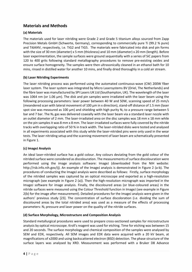
Materials and Methods (a) Materials
The materials used for laser nitriding were Grade 2 and Grade 5 titanium alloys sourced from Zapp Precision Metals GmbH (Schwerte, Germany), corresponding to commercially pure Ti (99.2 % pure) and Ti6Al4V, respectively, i.e. TiG2 and TiG5. The materials were fabricated into disk and pin forms with the size of 30 mm (diameter) x 5 mm (thickness) and 10 mm (diameter) x 20 mm (length). Before laser experimentation, the sample surfaces were ground sequentially with a series of SiC papers from 120 to 400 grits following standard metallography procedures to remove pre-existing oxides and ensure surface homogeneity. The samples were then ultrasonically cleaned in an ethanol bath for 10 mins, rinsed in distilled water for another 10 mins, and finally dried thoroughly in a cold air stream.
(b) Laser Nitriding Experiments
The laser nitriding process was performed using the automated continuous-wave (CW) 200W fiber laser system. The laser system was integrated by Micro Lasersystems BV (Driel, The Netherlands) and the fibre laser was manufactured by SPI Lasers UK Ltd (Southampton, UK). The wavelength of the laser was 1064 nm (or 1.06 µm). The disk and pin samples were irradiated with the laser beam using the following processing parameters: laser power between 40 W and 50W, scanning speed of 25 mm/s (meandered scan with lateral movement of 100 µm in x direction), stand-off distance of 1.5 mm (laser spot size was measured as 100 µm) and shielding with high purity N2 to a pressure range between 5 bar and 7 bar. The N2 gas was delivered coaxially with the laser beam via a standard laser nozzle with an outlet diameter of 2 mm. The laser-irradiated area on the disc samples was 18 mm x 18 mm while on the pin samples it was 8 mm x 8 mm. The laser-irradiated surfaces were fully covered by the nitride tracks with overlapping ratio of 50 % in track width. The laser-nitrided disks were tested and analysed in all experiments associated with this study while the laser-nitrided pins were only used in the wear tests. The laser nitriding setup and the scanning movement of laser beam are schematically presented in Figure 1.
(c) ImageJ Analysis
An ideal laser-nitrided surface has a gold colour. Any colours deviating from the gold colour of the nitrided surface were considered as discolouration. The measurements of surface discolouration were performed using the image analysis software: ImageJ (downloaded from the NIH website: http://rsb.info.nih.gov/ij). An example of the ImageJ analysis is demonstrated in Figure 2 (a-b). The procedures of conducting the ImageJ analysis were described as follows: Firstly, surface morphology of the nitrided samples was captured by an optical microscope and exported as a high-resolution micrograph (see example in Figure 2 (a)). Then the high-resolution micrograph was imported in the ImageJ software for image analysis. Finally, the discoloured areas (or blue-coloured areas) in the nitride surfaces were measured using the Colour Threshold function in ImageJ (see example in Figure 2(b) for the image after measurement). Detailed procedures for the ImageJ analysis were given in the authors’ previous study [23]. The concentration of surface discoloration (i.e. dividing the sum of discoloured areas by the total nitrided area) was used as a measure of the effects of processing parameters: N2 pressure and laser power on the quality of the nitride surfaces.
(d) Surface Morphology, Microstructure and Composition Analysis
Standard metallurgical procedures were used to prepare cross-sectioned samples for microstructure analysis by optical microscope. Kroll's reagent was used for etching. Time for etching was between 15 and 20 seconds. The surface morphology and chemical composition of the samples were analysed by SEM and EDX, respectively. All SEM images and EDX data were acquired with a 20 kV beam, at magnifications of x2000 and using backscattered electron (BSD) detection. The phase structure of the surface layers was analysed by XRD. Measurement was performed with a Bruker D8 Advance

5 | P a g e
diffractometer using copper K<alpha> radiation, nickel K<beta> filter, soller slits on the source and detector arm, divergence slit set to automatic to illuminate a 1 mm strip on the sample area, and the acceptance slit fixed at 9.5 mm. Standard theta/2-theta geometry was used (Bragg-Brentano).
(e) Vickers Hardness Measurements
Hardness values in the cross-sectional surfaces were measured using a Vickers hardness testing ma-chine under constant load of 200 kgf. Indent marks were made in different locations down from the surface nitride layer to base metal. The distance between each indent was 50 µm. It is known that grain boundary can affect the hardness by the Hall-Petch relation [24], i.e. grain boundary is a barrier to resist dislocation motion. In the Vickers hardness test, if the indent mark is larger than the grain size, the resulting hardness is an indication of the combined effect of grain interior and grain boundary. Depending on the location of indentation, the hardness might be varied due to the difference in ratio between areas of grain interior and boundary in the indent mark. Taking this into consideration, the reported result was an average hardness taken from seven indent marks in each region, namely ni-trided area, HAZ and base metal. The standard deviation was presented along with the average hard-ness to indicate the variance of measurements.
(f) Surface Roughness Measurements
Surface roughness values (Ra) were measured using a Mitutoyo surface roughness tester. The Ra val-ues were the average of 12 measurements taken in different locations in a direction perpendicular to the moving direction of laser beam.
(g) Friction and Wear properties
Tribostress was applied to titanium samples via self-mated sliding contacts of TiG2/TiG2 and TiG5/TiG5 pairs, as well as their laser-nitrided counterparts, by means of pin-on-disk tribometry (CMS Instru-ments SA, Peseux, Switzerland) in fetal bovine serum (FBS, Sigma Aldrich) as model synovial fluid. The contact configuration was flat-on-flat by employing flat-ended, cylindrical pin and disk as described above. The applied load, sliding speed, and total sliding distance were 10 N, 50 mm/s, and 400 m, respectively. Coefficient of friction (COF), defined as friction/load, was recorded over the entire sliding contacts with pin-on-disk tribometry. Wear properties of titanium samples were characterized in two different ways. Firstly, mass changes of both pin and disk before and after tribostress, i.e. gravimetric wear, were determined by balance. Secondly, distribution of wear particle size in FBS was determined by characterization of hydrodynamic diameter, DH, with dynamic light scattering (DLS, Zetasizer ZSP model, Malvern Instruments Ltd, Worcestershire, UK). FBS with dispersed wear debris was re-col-lected and transferred to cuvettes or culture tubes using a micropipette for DLS analysis and photog-raphy, respectively. No additional solvent was used for re-collection of FBS. Disposable cuvettes (PMMA, Brand) were used for DLS measurements and disposable round bottom sterile culture tubes (PS, VWR North America) were used for photography.

6 | P a g e
Results and Discussion (a) Effect of Process Parameters on the Quality of Nitride Surfaces
Figure 3 (a-f) shows the laser-nitrided surfaces of TiG2 and TiG5 produced by different N2 pressure. The results of TiG2 (in Figure 3 (a-c)) showed that a uniform and gold-coloured nitride surface can be produced by keeping the N2 pressure at 5 bar. When increasing the N2 pressure to 6 bar, surface discolouration (i.e. blue coloured oxides) started to appear. With further increase of N2 pressure to 7 bar, a majority of the nitride surface turned into blue colour, indicating a high level of surface discolouration. Similar observations can be found from the surfaces of nitrided TiG5 (in Figure 3 (d-f)), i.e. the level of surface discolouration increased with increasing N2 pressure. Image analysis was used to quantify the concentration of surface discolouration. The results are plotted in Figure 4. For the nitrided TiG2, the surface discolouration increased from 4.2 % to 41.2 % when increasing the N2 pressure from 5 bar to 7 bar. Likewise, increasing the N2 pressure from 5 bar to 7 bar caused an increase of surface discolouration from 2.6 % to 26.7 % in the nitrided TiG5. The major difference between the nitrided TiG2 and TiG5 surfaces lay in the tints of the gold colour, i.e. the TiG2 surface was brighter than that of TiG5. This indicates that the two materials reacted differently with the laser radiation at 1.06 µm wavelength in the laser nitriding process.
Intrusion of surrounding air in the laser-nitrided area can result in oxygen contamination due to the fact that Ti reacts faster with O2 than N2 to form TiO2. The enthalpy of formation of TiO2 from Ti is lower that of TiN, i.e. ∆Go values of TiO2 and TiN are -889.406 and -308.029 kJ/mol, respectively [25]. Furthermore, TiN can react with O2 to form TiO2 and TiNxOy in the topmost surface layer, i.e. oxidation of TiN has the ∆Go value of -580.32 kJ/mol [26]. Oxygen contamination can reduce the beneficial properties of TiN. Surface discolouration, as a consequence of the interference colour of TiO2, is an indicator to show the level of oxygen contamination. It has been reported by Chen et al. [15] that the mode of gas flow is crucial to minimize the intrusion of surrounding air. The N2 pressure should be kept at a low level to promote laminar flow around the substrate surface. If the N2 pressure is too high, turbulence flow will occur, causing the surrounding air to mix with the N2 pressure zone. The experimental results indicated that the N2 pressure of 5 bar is the threshold above which will result in rapid formation of blue oxide films.
Apart from the N2 pressure, laser power also has an important influence on the quality of the nitride surfaces. The effect of laser power can be reflected by the conditions of plasma generated in the laser nitriding process. Depending on the levels of laser power, three conditions of plasma can be observed (in Figure 5), namely (1) high brightness with severe sparking (i.e. 50W), (2) intermediate brightness with little sparking (i.e. 45W) and (3) low brightness without sparking (i.e. 40W). Defects (such as craters and cracks) and obvious discolouration were found from the surfaces associated with high brightness plasma and occurrence of sparking (i.e. conditions 1 and 2). Maintaining stable and low brightness plasma without sparking (i.e. condition 3) is important to produce a good quality nitride surface. This can be achieved by selecting a suitable level of laser power which is 40W. It has been reported that the presence of the laser-induced plasma can reduce the oxygen contamination. This is because the laser-induced plasma can increase the availability of dissociated and atomic N which reacts with the Ti substrate more efficiently than the surrounding, unexcited oxygen [14, 17, 18]. The nitride surfaces reported in the subsequent microstructure and wear resistance study were produced by the optimised set of parameters: 40 W (laser power), 25 mm (scanning speed), 1.5 mm (stand-off distance) and 5 bar (N2 pressure). The same set of parameters was used for laser nitriding of TiG2 and TiG5.
It is particularly to note that though the image analysis method employed in the present study is a simple and inexpensive tool to judge or screen the quality of the nitride layer, detailed analysis might be obtained by using spectrocolorimetry.

7 | P a g e
(b) Surface Morphology and Roughness Results of Laser-nitrided TiG2 and TiG5
The SEM BSD images of TiG2 and TiG5 before and after laser nitriding are shown in Figure 6(a-b) and 6(c-d) respectively. The nitride surfaces in TiG2 and TiG5 showed circular rosette-like structures. Such circular rosette-like structures, consisting of both ripples and radial lamellae, were about 100 μm in diameter with 50 μm repeat distance in the rows and 100 μm separation of the rows of spots. It has been reported that the rippled structure was resulted from the oscillation of the liquid titanium due to Marangoni convection and hydrodynamic processes driven by capillary waves acting on the melt pools [13, 27, 28]. In addition, networked structures can be observed from the nitride surface of TiG5, indicating that the melt pool dynamics of TiG5 differed from the case of TiG2. The calculated interaction time (i.e. laser spot diameter divided by scanning speed [29]) indicated that the laser radiation stopped at each location for about 4 milliseconds.
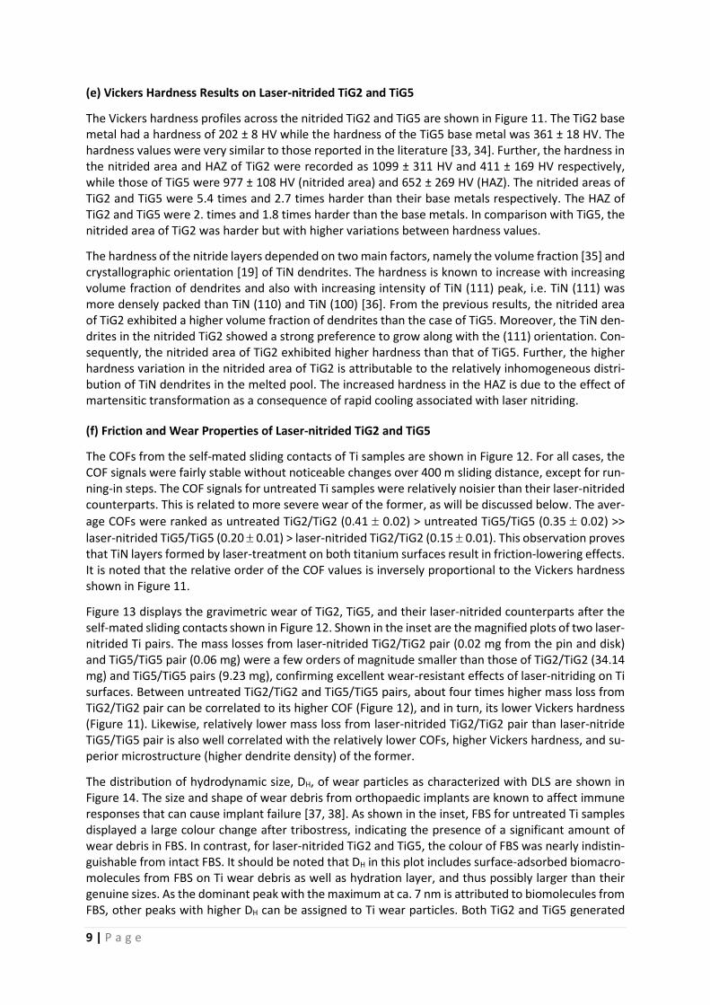
Figure 7 shows the comparison of surface roughness (i.e. Ra) of TiG2 and TiG5 before and after laser nitriding. From the roughness results, the Ra values of both TiG2 and TiG5 increased significantly after laser nitriding. The Ra values of TiG2 increased from 0.37 ± 0.015 µm (untreated) to 2.60 ± 0.18 µm (nitride) and from 0.13 ± 0.015 µm (untreated) to 3.57 ± 0.18 µm (nitride) for TiG5, respectively. The rough surface in the nitrided TiG2 and TiG5 is a consequence of the surface deformation caused by hydrodynamic and capillary effects.
(c) EDX Results of Laser-nitrided TiG2 and G5
Figure 8 (a-b) show the EDX mapping images of the laser-nitrided TiG2 and TiG5 surfaces. EDX analysis was used to map out the distribution of elements across the nitride surface, untreated surface and their boundary. As seen from Figure 8 (a-b), the nitride surfaces of TiG2 and TiG5 were enriched with more nitrogen as evidenced by the presence of higher amount of densely-populated yellow pixels (representing the N element). When examining the distribution of metal element (i.e. Ti) in the laser-nitrided TiG2 (in Figure 8 (a)), a clear difference existed between the nitride and untreated surfaces. Likewise, the metal elements, namely Ti, Al and V, distributed differently between the nitride and untreated surfaces of TiG5. Particularly, Al was found to preferably concentrate in the periphery of the circular rosette-like structures. The atomic composition (at.%) of metal elements in the laser-nitrided TiG2 and TiG5 surfaces are quantified and shown in Table 1. It can be seen that the metal elements after laser nitriding were reduced. In TiG2, the Ti reduced by 3.7 % after laser nitriding. For TiG5, the reduction was more significant in Al in comparison with Ti and V after laser nitriding, i.e. AI reduced by 57 % compared to 20 % and 37 % for Ti and V.
It is important to note that the EDX mapping results of N were only qualitative. Quantitative measurement of N by EDX is problematic because (1) the cross-section for N K-line X-ray production by an electron beam is quite low and (2) the nitrogen line would occur in a difficult part of the spectrum between carbon and oxygen, where the transmission of the thin window of the X-ray detector has an effect. Regarding the distribution of metal elements, the differences between the nitride and untreated surfaces can be explained by Marangoni convection, i.e. stirring of metal elements in the melt pools due to Marangoni forces. The preferential distribution of Al in the peripheral area is due to the metallurgical segregation of Al that occurs during rapid solidification in the laser melting process [30]. The reduction in percentage concentration of metal elements after nitriding is due to the incorporation of nitrogen in the microstructure.
(d) Microstructure and XRD Results of Laser-nitrided TiG2 and TiG5
The OM micrographs in Figure 9 (a-f) show the etched microstructure of the laser-nitrided TiG2 and TiG5. It can be seen from Figure 9 (b) that the laser-nitrided TiG2 exhibited a dendritic structure in the nitrided area. A thin, continuous layer formed on the topmost surface and the dendrites grew from the layer in the direction perpendicular to the surface. The dendrites were coarse and found to be densely packed with each other. A mushy zone (i.e. due to the stagnation effect of growing dendrites)

8 | P a g e
was observed near the boundary between the nitrided area and heat-affected zone (HAZ). The boundary line was irregular. The HAZ (in Figure 9 (c)) showed a finer microstructure compared with the nitrided area. The depth of the nitrided area and HAZ were around 68 µm and 40 µm, respectively. Beneath the HAZ, the microstructure of original base metal, namely equiaxed alpha phases can be seen in Figure 9 (a).
In the nitrided area of TiG5 (Figure 9 (d-f)), a distinct remelted zone can be found in the topmost surface with a clear boundary line separating the remelted zone and the previously-formed dendrite zone. Underlying the boundary, a graded microstructure can be seen, i.e. the TiN dendrites concentrated in the upper part and the amount of dendrites decreased in the lower part. In comparison with the TiG2, the dendrites were smaller with more space between them. No mushy zone was found but secondary needle-like phases appeared. An irregular boundary can still be observed between the nitrided area and HAZ. The HAZ (in Figure 9 (e)) showed a refined microstructure. The base metal beneath the HAZ (in Figure 9 (f)) exhibited a bimodal microstructure consisting of lamellar structure (alpha + beta area) and equiaxed alpha-phases. The depth of the nitrided zone was 87 µm and that of the HAZ was 56 µm.
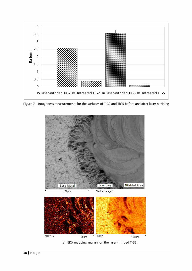
Figure 10 (a-b) show the results of XRD measurements on TiG2 and TiG5 before and after laser nitriding. As observed from Figure 10 (a-b), the laser-nitrided TiG2 and TiG5 comprised of two distinct phases: cubic titanium nitride (c-TiN) preferentially grown on (111) and (200) planes and hexagonal alpha-titanium on (011) plane. In the case of nitrided TiG2, the intensity of the TiN (111) peak was slightly higher than that of the TiN (200), whereas the intensity of the TiN (200) peak in the nitrided TiG5 was much stronger than that of the TiN (111) peak. No beta phases were detected from the laser-nitrided TiG5 surface. Moreover, only a very small amount of TiO2 (101) was detected from the nitride surfaces of TiG2 and TiG5, indicating that the high pressure zone created between the nozzle and the surface was effective in blocking the oxygen intruding from the open air.
According to the Ti-N phase diagram, four different phases, namely alpha Ti, beta Ti, Ti2N and TiN can be found in the microstructure when Ti reacts with N. The resulting microstructure is determined by the temperature and nitrogen concentration in the thermomechanical process. From the XRD results, beta-Ti and Ti2N were not detected. The microstructure in the nitrided area of TiG2 and TiG5 was a mixture of the TiN dendrites and the nitrogen-rich alpha Ti phases. The absence of beta-Ti in the nitrided TiG5 is due to the alpha stabilising effect of nitrogen which suppressed the formation of beta phases during solidification.
The model proposed by Labudovic et al. [31] suggests that solidification of the nitrided area commences with the TiN dendrites due to its higher melting point (~2,930 °C) compared to the alpha phases (~1670 °C), i.e. TiN forms first at the surface of the melt pool when it solidifies. In the laser nitriding process, a fully covered surface was produced by overlapping the laser beam with the adjacent previously-nitrided area. It has been reported that the temperature in the melt pool of the previously-nitrided area can exceed the melting point of TiN and cause remelting of the surface TiN dendrites. Consequently, the thin and continuous surface layer in the nitrided TiG2 was the remelted TiN dendrites. On the other hand, it is not surprising to see the irregular boundary line between the nitrided area and HAZ in the TiG2 and TiG5 samples given that the formation of TiN is an exothermic reaction. The additional heat energy released by the formation of TiN dendrites near the boundary can cause local melting in the boundary area. The situation was more obvious in the TiG2 because of the presence of mushy zone.
It should be noted that the differences of dendrite size and distribution between TiG2 and TiG5 are attributed to the differences in temperature and nitrogen concentration in the melt pools of the two materials due to their different interactions with the laser radiation in the near-infrared range, namely 1.06 µm (as described in the previous sections). The secondary needle-like phases in the nitrided area of TiG5 resulted from the rapid cooling associated with the laser nitriding process, triggering the martensitic transformation of high temperature beta phase to alpha prime phase [32].
9 | P a g e
(e) Vickers Hardness Results on Laser-nitrided TiG2 and TiG5
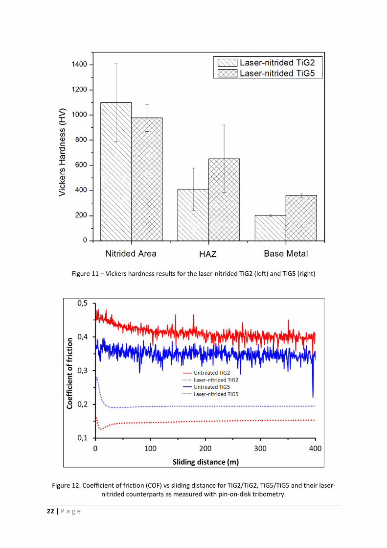
The Vickers hardness profiles across the nitrided TiG2 and TiG5 are shown in Figure 11. The TiG2 base metal had a hardness of 202 ± 8 HV while the hardness of the TiG5 base metal was 361 ± 18 HV. The hardness values were very similar to those reported in the literature [33, 34]. Further, the hardness in the nitrided area and HAZ of TiG2 were recorded as 1099 ± 311 HV and 411 ± 169 HV respectively, while those of TiG5 were 977 ± 108 HV (nitrided area) and 652 ± 269 HV (HAZ). The nitrided areas of TiG2 and TiG5 were 5.4 times and 2.7 times harder than their base metals respectively. The HAZ of TiG2 and TiG5 were 2. times and 1.8 times harder than the base metals. In comparison with TiG5, the nitrided area of TiG2 was harder but with higher variations between hardness values.
The hardness of the nitride layers depended on two main factors, namely the volume fraction [35] and crystallographic orientation [19] of TiN dendrites. The hardness is known to increase with increasing volume fraction of dendrites and also with increasing intensity of TiN (111) peak, i.e. TiN (111) was more densely packed than TiN (110) and TiN (100) [36]. From the previous results, the nitrided area of TiG2 exhibited a higher volume fraction of dendrites than the case of TiG5. Moreover, the TiN den-drites in the nitrided TiG2 showed a strong preference to grow along with the (111) orientation. Con-sequently, the nitrided area of TiG2 exhibited higher hardness than that of TiG5. Further, the higher hardness variation in the nitrided area of TiG2 is attributable to the relatively inhomogeneous distri-bution of TiN dendrites in the melted pool. The increased hardness in the HAZ is due to the effect of martensitic transformation as a consequence of rapid cooling associated with laser nitriding.
(f) Friction and Wear Properties of Laser-nitrided TiG2 and TiG5
The COFs from the self-mated sliding contacts of Ti samples are shown in Figure 12. For all cases, the COF signals were fairly stable without noticeable changes over 400 m sliding distance, except for run-ning-in steps. The COF signals for untreated Ti samples were relatively noisier than their laser-nitrided counterparts. This is related to more severe wear of the former, as will be discussed below. The aver-age COFs were ranked as untreated TiG2/TiG2 (0.41 ± 0.02) > untreated TiG5/TiG5 (0.35 ± 0.02) >> laser-nitrided TiG5/TiG5 (0.20 ± 0.01) > laser-nitrided TiG2/TiG2 (0.15 ± 0.01). This observation proves that TiN layers formed by laser-treatment on both titanium surfaces result in friction-lowering effects. It is noted that the relative order of the COF values is inversely proportional to the Vickers hardness shown in Figure 11.
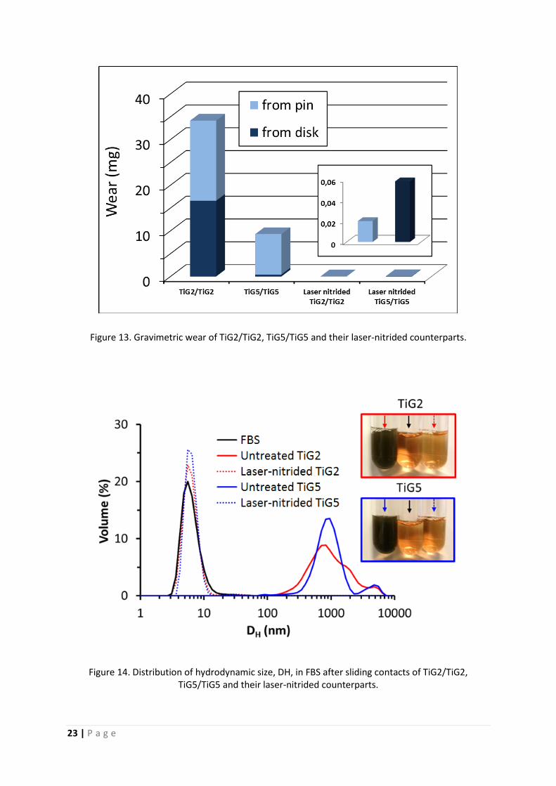
Figure 13 displays the gravimetric wear of TiG2, TiG5, and their laser-nitrided counterparts after the self-mated sliding contacts shown in Figure 12. Shown in the inset are the magnified plots of two laser-nitrided Ti pairs. The mass losses from laser-nitrided TiG2/TiG2 pair (0.02 mg from the pin and disk) and TiG5/TiG5 pair (0.06 mg) were a few orders of magnitude smaller than those of TiG2/TiG2 (34.14 mg) and TiG5/TiG5 pairs (9.23 mg), confirming excellent wear-resistant effects of laser-nitriding on Ti surfaces. Between untreated TiG2/TiG2 and TiG5/TiG5 pairs, about four times higher mass loss from TiG2/TiG2 pair can be correlated to its higher COF (Figure 12), and in turn, its lower Vickers hardness (Figure 11). Likewise, relatively lower mass loss from laser-nitrided TiG2/TiG2 pair than laser-nitride TiG5/TiG5 pair is also well correlated with the relatively lower COFs, higher Vickers hardness, and su-perior microstructure (higher dendrite density) of the former.
The distribution of hydrodynamic size, DH, of wear particles as characterized with DLS are shown in Figure 14. The size and shape of wear debris from orthopaedic implants are known to affect immune responses that can cause implant failure [37, 38]. As shown in the inset, FBS for untreated Ti samples displayed a large colour change after tribostress, indicating the presence of a significant amount of wear debris in FBS. In contrast, for laser-nitrided TiG2 and TiG5, the colour of FBS was nearly indistin-guishable from intact FBS. It should be noted that DH in this plot includes surface-adsorbed biomacro-molecules from FBS on Ti wear debris as well as hydration layer, and thus possibly larger than their genuine sizes. As the dominant peak with the maximum at ca. 7 nm is attributed to biomolecules from FBS, other peaks with higher DH can be assigned to Ti wear particles. Both TiG2 and TiG5 generated

10 | P a g e
wear particles with the DH ranging from ca. 100 nm to 10,000 nm, although TiG2 is slightly more widely distributed than TiG5. However, the Z-average for TiG5 (689.9 nm) was somewhat larger than that of TiG2 (493.1 nm). The Z-average of laser-nitrided TiG2 and TiG5 were 65.5 nm and 65.0 nm, respectively. The excellent wear-resistant effect of laser-nitriding of Ti surfaces was therefore confirmed by DLS. Conclusions
In this work, the possibilities of performing laser nitriding on TiG2 and TiG5 surfaces by CW fibre laser in open air environment were investigated. Image analysis was carried out to quantify the concentra-tion of discolouration in the nitride surfaces. The cross-section microstructure, surface features and mechanical properties of the laser-formed nitride layers were analysed. The following conclusions were reached:
(a) TiG2 and TiG5 reacted differently with the laser radiation at 1.06 µm wavelength in laser nitriding as evidenced by differences in the surface colour and morphology, as well as the size and distri-bution of dendrites in the nitride layers;
(b) Laser power and N2 pressure were found to be critical to affect the quality of the nitride surfaces;
(c) The optimized processing parameters to produce the uniform and gold-coloured nitride layers in TiG2 and TiG5 were identified as 40 W (laser power), 25 mm/s (scanning speed), 1.5 mm (stand-off distance) and 5 bar (N2 pressure);
(d) The hardness of nitride layers was dependent on the volume fraction and crystallographic orien-tation of TiN dendrites.
(e) Both friction and wear properties were strongly affected by the hardness and microstructure of Ti samples and direct laser nitriding led to substantial improvement in their wear resistant properties.
Acknowledgment The work described in this paper was supported by research grant from the Queen's University Belfast (Start-up Research Fund: D8201MAS), United Kingdom.

11 | P a g e
References 1. Abu-Amer, Y., Darwech, I., and Clohisy, J.C., Aseptic loosening of total joint
replacements: mechanisms underlying osteolysis and potential therapies. Arthritis Research & Therapy. 9 (2007) S1-S6.
2. Cordova L.A., Stresing V., Gobin B., Rosset P., Passuti N., Gouin F., Trichet V., Layrolle P., and Heymann D., Orthopaedic implant failure: aseptic implant loosening–the contribution and future challenges of mouse models in translational research, Clinical Science, 127 (2014) 277-293.
3. Ignatiev, M., Kovalev, E., Melekhin, I., Smurov, I.Y., and Sturles, S. Investigation of the hardening of a titanium alloy by laser nitriding, Wear, 166 (1993) 233-236.
4. Xin, H., Mridha, S., and Baker, T.N., The effect of laser surface nitriding with a spinning laser beam on the wear resistance of commercial purity titanium, Journal of Material Science, 31 (1996) 22-30.
5. Schaaf, P. Laser nitriding of metals, Progress in Materials Science, 47 (2000) 1-161. 6. Guo, B., Zhou, J., Zhang, S., Zhou, H., Pu, Y., Chen, J., Microstructure and tribological properties of
in situ synthesized TiN/TiN3 Al intermetallic matrix composite coatings on titanium by laser cladding and laser nitriding, Materials Science & Engineering A, 480 (2008) 404-410.
7. Tian, Y.S., Chen, C.Z., Li, S.T., and Huo, Q.H., Research progress on laser surface modification of titanium alloys, Apply Surface Science, 242 (2005) 177-184.
8. Balla, V.K., Bhat, A., Bose, S., and Bandyopadhyay, A., Laser processed TiN reinforced Ti6Al4V composite coatings, Journal of the Mechanical Behavior of Biomedical Materials, 6 (2012) 9-20.
9. Schaaf, P., Laser nitriding of metals, Progress in Materials Science, 47 (2002) 1-161. 10. Hoche, D., Rapin, G., & Schaaf, P. FEM simulation of the laser plasma interaction during laser
nitriding of titanium, Applied Surface Science, 254 (2007) 888-892. 11. Schaaf, P., & Höche, D. (2009). Free electron laser synthesis of functional coatings. In Miotello, A.,
& Ossi, P.M. (Ed.) Laser-surface interactions for new materials production (pp 295-306). Berlin Heidelberg: Springer.
12. Schaaf, P., & Höche, D. (2014). Industrial applications of laser-material interactions for coating formation. In Castillejo, M., Ossi, P.M., & Zhigilei, L. (Ed.), Lasers in materials science (pp. 345-357). Switzerland: Springer International Publishing.
13. Höche, D., and Schaaf, P., Laser nitriding: Investigations on the model system TiN: A review, Heat Mass Transfer, 47 (2011) 519-540.
14. Kloosterman, A.B., and De Hosson, J.T.M., Microstructural characterization of laser nitrided titanium, Scripta Metallurgica et Materialia. 33 (1995) 567–573.
15. Chen, X., Wu, G., Wang, R., and Han, W., Laser nitiding of titanium alloy in the atmosphere environment, Surface & Coatings Technology, 201 (2007) 4843-4846.
16. Yu, H., Sun, F., and Zhang, J., Laser and plasma nitriding of titanium using CW-CO2 lasers in the atmosphere, Current Apply Physics, 9 (2009) 227-223.
17. Nassar, A.R., Akarapu, R., Copley, S.M., and Todd, J.A., Investigations of laser-sustained plasma and its role in laser nitriding of titanium. Journal of Physics D: Applied Physics, 45 (2012) 185401.
18. Kamata, A.M., Stephen M. Copley, S.M., and Todd, J.A., Effect of processing parameters on microstructure during laser-sustained plasma (LSP) nitriding of commercially-pure titanium, Acta Materialia, 107 (2016) 72-82.
19. May, A., Agarwal, N., Lee, J., Lambert, M., Akkan, C.K., Nothdurft, F.P., and Aktas, O.C., Laser induced anisotropic wetting on Ti-6Al-4V surfaces, Materials Letters, 138 (2015) 21-24.
20. Zhang, Y., Yan, M., Yu, A., Mao, H., Zhang, J., Inhibitory effects of beta-tricalciumphosphate wear particles on osteocytes via apoptotic response and Akt inactivation, Toxicology, 297 (2012) 57-67.
21. Omata, S., Sawae, Y., Murakami, T., Effect of poly(vinyl alcohol) (PVA) wear particles generated in water lubricant on immune response of macrophage, Biosurface and biotribology, 1 (2015) 71-79.
22. Akchurin, A., Bosman, R., Lugt, P.M., and van Drogen, M., Analysis of wear particles formed in boundary-lubricated sliding contacts, Tribology Letter (2016) 63:16.

12 | P a g e
23. Chan, C.W., and Smith, G.C., Fibre laser joining of highly dissimilar materials: Commercially pure Ti and PET hybrid joint for medical device applications, Materials and Design, 103 (2016) 278-292.
24. Hansen, N., Hall–Petch relation and boundary strengthening, Scripta Materialia, 51 (2004) 801-806.
25. Chase, M.W., NIST-JANAF Thermochemical Tables, Fourth Edition. Journal of Physical and Chemical Reference Data, Monograph 9 (1998) 1-1951.
26. Wittmer, M., Noser, J., and Melchior, H., Oxidation kinetics of TiN thin films, Journal of Applied Physics, 52 (1981) 6659-6664.
27. Gyorgy, E., Perez del Pino, A., Serra, P., & Morenza, J.L., Microcolumn development on titanium by multipulse laser irradiation in nitrogen, Journal of Materials Research, 18 (2003) 2228-2234.
28. Abboud, J.H., Effect of processing parameters on titanium nitrided surface layers produced by laser gas nitriding, Surface and Coatings Technology, 214 (2013) 19-29.
29. Suder, W.J., and Williams, S.W. Investigation of the effects of basic laser material interactionparameters in laser welding, Journal of Laser Applications, 24 (2012) 032009.
30. Vaithilingam, J., Prina, E., Goodridge, R.D., Hague, R.J.M., Edmondson, S., Rose, F.R.A.J., and Christie, S.D.R, Surface chemistry of Ti6Al4V components fabricated using selective laser melting for biomedical applications, Materials Science and Engineering C, 67 (2016) 294-303.
31. Labudovic, M., Kovacevic, R., Kmecko, I., Khan, T.l., Blecic, D., and Blecic, Z., Mechanism of surface modification of the Ti-6Al-4V alloy using a gas tungsten arc heat source, Metallurgical and Materials Transactions A, 30 (1999) 1597-1603.
32. Fan, Y., Cheng, P., Yao, Y.L., Yang, Z., and Egland, K., Effect of phase transformations on laser forming of Ti-6Al-4V alloy, Journal of Applied Physics, 98 (2005) 013518.
33. Sicknan Soares da, R., Gelson Luis, A., Guilherme Elias Pessanha, H., & Mauro Antônio de Arruda, N., Vickers hardness of cast commercially pure titanium and Ti-6Al-4V alloy submitted to heat treatments. Brazilian Dental Journal, 17 (2006) 126-129.
34. Poondla, N., Srivatsan, T.S., Patnaik, A., and Petraroli, M., A study of the microstructure and hardness of two titanium alloys: Commercially pure and Ti–6Al–4V, 486 (2009) 162-167.
35. Baker, T.N., Laser surface modification of Ti alloys. In: Surface Engineering of Light Alloys, Aluminium, Magnesium and Titanium Alloys. 2010: Woodhead Publications.
36. Vora, H.D., Rajamure, R.S., Dahotre, S.N., Ho, Y.H., Banerjee, R., and Dahotre, N.B., Integrated experimental and theortical approach for corrosion and wear evaluation of laser surface nitrided Ti-6Al-4V, biomaterial in physiological solution, 37 (2014) 153-164.
37. Mishra, P.K., Wu, W., Rozo, C., Hallab, N.J., Benevenia J., and Gause W.C., Micrometer-sized titanium particles can induce potent Th2-type responses through TLR4-Independent pathways, Journal of Immunology, 187 (2011) 6491-6498.
38. St Pierre, C.A., Chan, M., Iwakura, Y., Ayers, D.C., Kurt-Jones, E.A., and Finberg, R.W., Periprosthetic osteolysis: Characterizing the innate immune response to titanium wear-particles, Journal of Orthopaedic Research, 28 (2010) 1418-1424.

13 | P a g e
Table and Figures Table 1 – EDX composition results (metal elements) of TiG2 and TiG5 before and after laser nitriding
Elements Untreated TiG2
(at. %) Laser-nitrided TiG2
(at. %) Untreated TiG5
(at. %) Laser-nitrided TiG5
(at. %) Ti 77.3 74.5 77.6 62.1 Al --- --- 8.6 3.7 V --- --- 2.7 1.7

14 | P a g e
Figure 1 – Schematic diagram of the laser nitriding setup (left) and the scanning movement of the laser beam (right). High purity N2 is delivered coaxially via the laser nozzle. High pressure N2 zone is created between the substrate surface and nozzle tip to prevent O2 intruding from surrounding air.
Figure 2 (a-b) – Example of ImageJ analysis showing the measurement of discoloured areas (i.e. blue-coloured area) in the TiG2 nitrided surface. The discoloured areas predominantly appeared in the crests of the nitride tracks. The shaded area in (b) corresponds to the blue-coloured area in (a). The laser processing parameters: laser power, scanning speed, stand-off distance and N2 pressure were 40 W, 25 mm/s, 1.5 mm and 6 bar respectively.

15 | P a g e
Figure 3 (a-f) – Optical micrographs for the surfaces of laser-nitrided (a-c) TiG2 and (d-f) TiG5 produced by different N2 pressure (5, 6 and 7 bar) in the laser nitriding experiments. Surface discolouration started to appear at 6 bar and became significant at 7 bar. The laser processing parameters: laser power, scanning speed and stand-off distance were 40 W, 25 mm/s and 1.5 mm, respectively.

16 | P a g e
Figure 4 – Effect of changing the N2 pressure on the concentration of discolouration for the laser-nitrided TiG2 and TiG5 surfaces. The surface discolouration was measured by ImageJ (i.e. measured the concentration of blue colour appeared in the nitrided surfaces).
Figure 5 – Effect of changing the laser power on the plasma conditions during the laser nitriding process. The laser power used to generate the plasma in condition 1 was 50W, condition 2 was 45W and condition 3 was 40W. Other processing parameters, such as scanning speed, stand-off distance, and N2 pressure were kept constant, i.e. 25 mm/s, 1.5 mm and 5 bar respectively. The diameter of the laser-induced plasma (from left to right) was estimated to be 8.6 mm, 5.4 mm, and 2.1 mm, respectively.

17 | P a g e
Figure 6 (a-d) – SEM micrographs taken at the untreated and laser-nitrided surfaces for (a-b) TiG2 and (c-d) TiG5. Circular rosette-like structures, consisting of ripples and lamellae in radial direction, can be observed from the laser-nitrided surfaces of TiG2 and TiG5. Additionally, networked structures can be found in the case of TiG5. The calculated interaction time indicated that the laser radiation stopped at each location for about 4 milliseconds.
18 | P a g e
Figure 7 – Roughness measurements for the surfaces of TiG2 and TiG5 before and after laser nitriding
(a) EDX mapping analysis on the laser-nitrided TiG2
0
0.5
1
1.5
2
2.5
3
3.5
4Ra
(um
)
Laser-nitrided TiG2 Untreated TiG2 Laser-nitrided TiG5 Untreated TiG5

19 | P a g e
(b) EDX mapping image of laser-nitrided TiG5
Figure 8 (a-b) – EDX mapping images for the laser-nitrided (a) TiG2 – Ti, N and (b) TiG5 – Ti, Al, V and N across the laser-nitrided area, base metal and their boundary

20 | P a g e
Figure 9 (a-f) – Cross-sectional micrographs for the laser-nitrided (a-c) TiG2 and (e-f) TiG5 at different areas: nitrided area, HAZ and base metal. Dendritic structure can be seen in the nitrided areas of TiG2 and TiG5. A remelted layer/zone can be observed in the topmost surface and a refined structure can be seen from the HAZ. The base metal of TiG2 showed a typical equiaxed alpha microstructure while that of the TiG2 exhibited a bimodal microstructure consisting of lamellar structure (alpha + beta area) and equiaxed alpha-phases.
21 | P a g e
(a) XRD patterns for untreated and laser-nitrided TiG2
(b) XRD patterns for untreated and laser-nitrided TiG5
Figure 10 (a-b) – XRD patterns for the untreated and laser-nitrided (a) TiG2 and (b) TiG5
22 | P a g e
Figure 11 – Vickers hardness results for the laser-nitrided TiG2 (left) and TiG5 (right)
Figure 12. Coefficient of friction (COF) vs sliding distance for TiG2/TiG2, TiG5/TiG5 and their laser-nitrided counterparts as measured with pin-on-disk tribometry.
23 | P a g e
Figure 13. Gravimetric wear of TiG2/TiG2, TiG5/TiG5 and their laser-nitrided counterparts.
Figure 14. Distribution of hydrodynamic size, DH, in FBS after sliding contacts of TiG2/TiG2, TiG5/TiG5 and their laser-nitrided counterparts.