fiber laser welding of alsicoated presshardened steel regarding fiber laser welding of phs. kim et...
TRANSCRIPT

Introduction In recent years, automotive indus-tries have reduced vehicle weight by re-placing conventional low-strengthsteels with advanced high-strengthsteels (AHSSs), and ultrahigh-strengthsteels (UHSSs). The higher specificstrength, thinner gauge of AHSS andUHSS sheets provide superior mechani-cal properties compared to the otherhigh-strength, low-alloy steels (Ref. 1).By decreasing the thickness of thesheets, the weight of the vehicles can bereduced, improving fuel efficiency anddecreasing greenhouse gas emissions tobenefit the environment (Refs. 2, 3).
Among the other AHSS, press-hardened steel (PHS), such as the USI-BOR® glade, offers high ultimate tensilestrength (1500 MPa) in the hot-stamped condition. In the as-quenchedstate, PHS exhibits high strength andlow formability, making it difficult toform complex parts (Ref. 1). Conse-quently, these steels are intended for ahot stamping process, i.e., forming atthe austenite temperature and subse-quently quenching to form martensite.In order to prevent surface oxidationand decarburization, PHS sheets areusually coated with various coatings,such as Al-Si, Zn, or Zn-Ni alloys (Ref.4). Among these coating alloys, Al-Si
offers better corrosion and high-tem-perature oxidation resistance (Ref. 4). Automotive components commonlymade with PHS are A-pillars, B-pillars,door rings, bumpers, roof rails, andtunnels (Ref. 5), all of which are usual-ly made from laser-welded blanks(LWBs), also known as tailor-weldedblanks (TWBs). Other property tailor-ing methods such as partial temper-ing, partial quenching, and post tem-pering of the monolithic sheets can beemployed (Ref. 6). Utilization of PHSmaterials combined with LWB tech-nology provides weight saving, materi-al cost reduction, improved part per-formance, and simplifies the manufac-turing process (Refs. 7–9). Fiber laserwelding is considered to be preferredin this application compared to otherforms of laser sources, considering itoffers a small beam diameter, flexiblebeam delivery, higher precision and ac-curacy, less thermal distortion, andhigh-plug efficiency (Refs. 10, 11). Apart from the chemical composi-tion of steels, the presence of a coatingalso influences the properties ofLWBs. It has been reported that thecoated steels are prone to more weld-ing defects such as weld concavity(Ref. 12) and coating mixing into theweld pool (Refs. 13, 14), compared touncoated steels. One of the major is-sues associated with using coated PHSis the presence of the Al-Si coating onthe surface, which affects the weldingprocess. During laser welding, thecoating is mixed into the fusion zone
WELDING RESEARCH
MAY 2016 / WELDING JOURNAL 147-s
SUPPLEMENT TO THE WELDING JOURNAL, MAY 2016Sponsored by the American Welding Society and the Welding Research Council
Fiber Laser Welding of AlSiCoated PressHardened Steel
The mixing and formation of the AlSi coating’s deltaferrite phase was the key factor for premature failure of the laserwelded joints
BY D. C. SAHA, E. BIRO, A. P. GERLICH, AND Y. N. ZHOU
ABSTRACT The effect of an AlSi coating on the microstructure and mechanical properties offiber laserwelded, presshardened steel is examined in the present work. It is shownthat mixing of the AlSi coating significantly modified the fusion zone microstructure,which was found to be a combination of martensite and delta ferrite in both the weldedasreceived and hotstamped conditions. In contrast, a uniform distribution of alpha ferrite and martensite was observed when the asreceived sheet was welded then hotstamped. The ferrite phase was found to be rich in Al and Si, which retarded the kineticsof martensite formation, increasing the ferrite fraction after hot stamping of the weldedcoupon. Micro and nanoscale hardness measurements on ferrite suggest it is a softerphase compared to martensite; therefore, inducing strain localization and prematurefracture during tensile tests occurred. The strength of allwelded joints was found to bedependent on ferrite phase fractions, since this promoted premature fracture, and deteriorated joint strength and ductility.
KEYWORDS • Fiber Laser Welds • PressHardened Steel • Coating Mixing • Weld Solidification • Delta Ferrite
D. C. SAHA ([email protected]), A. P. GERLICH, and Y. N. ZHOU are with the Department of Mechanical and Mechatronics Engineering,University of Waterloo, Waterloo, Ontario, Canada. E. BIRO is with ArcelorMittal Global Research, Hamilton, Ontario, Canada.
Saha 5-16.qxp_Layout 1 4/14/16 6:18 PM Page 147

(FZ), and thereby changes the localchemistry and equilibrium phases(Ref. 15). Hence, heterogeneous phas-es can form and adversely affect themechanical properties (Refs. 14, 16). To date, limited work has been pub-lished regarding fiber laser welding ofPHS. Kim et al. (Ref. 13) investigatedthe laser welding properties of Al-Si-coated PHS and found an intermetallicphase at fusion boundary. Other stud-ies (Refs. 17, 18) also reported inter-metallic phase formation in the FZwhile welding Al-Si-coated PHS. Stud-ies done on laser welding of Al-Si-coat-ed PHS have claimed that a secondphase formed in either the FZ or thefusion boundary was an intermetalliccompound, without identifying it;however, it was shown to be related tothe presence of Al content. Recently, Kang et al. (Ref. 19) inves-tigated the influence of beam size andhot stamping parameters (temperatureand time) on the FZ microstructure for-mation. They found that the fraction ofmartensite increases in the FZ when alarger beam size, higher austenizationtemperature, and time are considered.Industries are now dealing with this is-sue by employing a dedicated weldingprocess known as laser ablation (Refs.17, 18), which uses a short multi-im-pulse laser to remove the Al-Si coating,leaving behind only an intermediate
Fe2Al5 andFeAl3 layer. The forma-tion mecha-nisms of producing the second phasein the FZ and their effect on mechani-cal properties are not well understood.In this study, the effect of the coatingwill be examined in terms of the for-mation of various phases in the FZ,and their impact on the microhardnessand tensile properties. In the presentstudy, all of the possible processingcombinations of PHS joints will beconsidered, such as as-received welded(ARW), as-received welded then hotstamped (ARWHS), and hot stampedwelded (HSW). The properties of indi-vidual phases within the FZ will beevaluated using Vickers microhardnessand nanoindentation.
Experimental Methodology Fiber laser welds were made on 1.00-mm-thick Al-Si-coated PHS, where theyield strength and ultimate tensilestrength of the as-received sheets areabout 424 and 570 MPa, respectively.The chemical composition and mechan-ical properties are listed in Tables 1 and2, respectively. For hot stamping, as-received sheets were austenized in a fur-nace at 930°C for 5 min, and then trans-
ferred (within 10 s) to flat dies, wherequenching was done to ensure fullymartensite microstructure (Refs. 1, 21).The cooling rate was measured with athermocouple welded to the dies, andconfirmed to be about 31°C/s, which isidentical to the critical cooling rate ofmartensite formation of PHS as report-ed in the literature (Refs. 1, 22). Welds were made using an IPG Pho-tonics ytterbium fiber laser system(model: YLS-6000-S2); the details of thesystem can be found in previous studies(Ref. 23). The welds were inspected forconcavity, porosity, and other defects inaccordance with General Motors engi-neering standards (GM4485M) (Ref.24). The minimum concavity of thejoint was estimated to be within the in-dustrial acceptable range (below 20%)(Ref. 25). Welds were made in the bead-on-plate configuration, and the materi-als, hot stamping conditions, and weld-ing parameters can be found in Table 3. The mechanically ground and pol-ished specimens were etched with 5%Nital solution for 2 s to reveal the mi-crostructure. Microstructures werecharacterized using an optical micro-scope and a field-emission scanningelectron microscope (FE-SEM, model:
WELDING RESEARCH
WELDING JOURNAL / MAY 2016, VOL. 95148-s
Fig. 1 — SEM micrographs of the AlSi coating and line scanning of Al, Si, and Fe. A and C — Asreceived condition; B andD — hotstamped condition.
Fig. 2 — Typical base metal microstructure of the investigated steels.A — Asreceived condition; B — hotstamped condition.
Fig. 3 — Fiber laserwelded PHS steel without coating on the surfaceshowing. A — The full weld profile; B — the fully martensitic FZ.
Table 1 — Nominal Compositions of the PressHardened Steel (PHS) Used in This Investigation
C Mn P S Si B Mo Al Cr Ti CEN (Ref. 20)
0.23 1.22 0.013 0.001 0.27 0.0032 0.02 0.039 0.20 0.037 0.48
A A
A
C D
B B
B
Saha 5-16.qxp_Layout 1 4/14/16 6:18 PM Page 148
Zeiss Leo 1550). The equilibrium binaryphase diagram of the studied steel wascalculated using commercial thermody-namic software ThermoCalc. Vickers microhardness was meas-ured under 200-g load and 15-s dwelltime. In order to avoid interferencefrom the strain fields developed by theadjacent indents, a spacing of at leastthree times the diagonal was main-tained between indents, as recommend-ed by ASTM Standard E384 (Ref. 26).Nanoindentation was performed on theetched specimens using 5000-mN loadfor 20 s using a Hysitron TriboindenterTI-900 equipped with a scanning probemicroscope. Transverse tensile speci-mens were machined as per ASTM Stan-dard E8 (Ref. 27) with the sample di-mensions shown in Refs. 28, 29. Thetensile tests were carried out using acomputerized tensile testing machine ata crosshead speed of 1 mm/min.
Results
Coating and Base Metal Characteristics
Figure 1 shows typical morphologyof the coating in the as-received (Fig.1A) and hot-stamped (Fig. 1B) condi-tion. As-received material has a coatingthickness of about 15–20 mm, whichwas transformed and diffused into thesteel to a depth of about 30–40 mm dur-ing hot stamping. It was reported thatthe growth of the coating thickness ishighly dependent on the austenizationtemperature and time. Both parametersincrease the coating thickness (Ref. 4).
Coating of the as-received steel consistsof an Al matrix with elongated pure Siparticles (Fig. 1A), which formed by aeutectic reaction during the aluminizingprocess (Ref. 30). An intermediate layerexists between the coating, and thesteel substrate has a thickness of about4–6 mm (Ref. 31) with a composition ofFe2SiAl7. In addition, a thin layer (<1 mmthickness) of FeAl3 was also observedbetween the steel substrate and theFe2SiAl7 layer, as shown in the inset ofFig. 1A (Ref. 30). Energy-dispersivespectroscopy (EDS) line scanning ofthe coating (Fig. 1C) shows a thin Si-enriched layer at the outer surface ofthe coating. A multilayered coating isformed during heat treatment (Refs. 4,30–34), as shown in Fig. 1B and D. Atotal of five distinct microstructuralregions can be found in the coating inthe hot-stamped condition, with dif-ferent morphologies and compositions(Refs. 30, 31, 34). The microstructure of the as-received steel is comprised predomi-nantly of ferrite, pearlite, and a smallamount of martensite at the grainboundaries — Fig. 2A. A typical mor-
phology of lath martensite can be foundin the hot-stamped condition — Fig.2B. Laths are parallel to each other andsome of the laths contain distributedcarbides, which resulted from the au-totempering (Ref. 35).
Microstructure of the Welds
To investigate the influences of theAl-Si coating on the FZ microstructure,the coating was removed chemically bydipping into a solution of 10% sodiumhydroxide (NaOH) in deionized water.Figure 3 shows the full weld profile andthe FZ microstructure; a fully marten-sitic microstructure was obtained beforeand after hot stamping of the weldedcoupon.
AsReceived Welded (ARW)
Bead-on-plate welds were made withthe welding parameters as specified inTable 3. From Fig. 4, it is noted that thethermal cycle employed during weldinghas drastically changed the HAZ and FZmicrostructures. Although the fiberlaser welding process involves rapidheating and cooling, the FZ was not
WELDING RESEARCH
MAY 2016 / WELDING JOURNAL 149-s
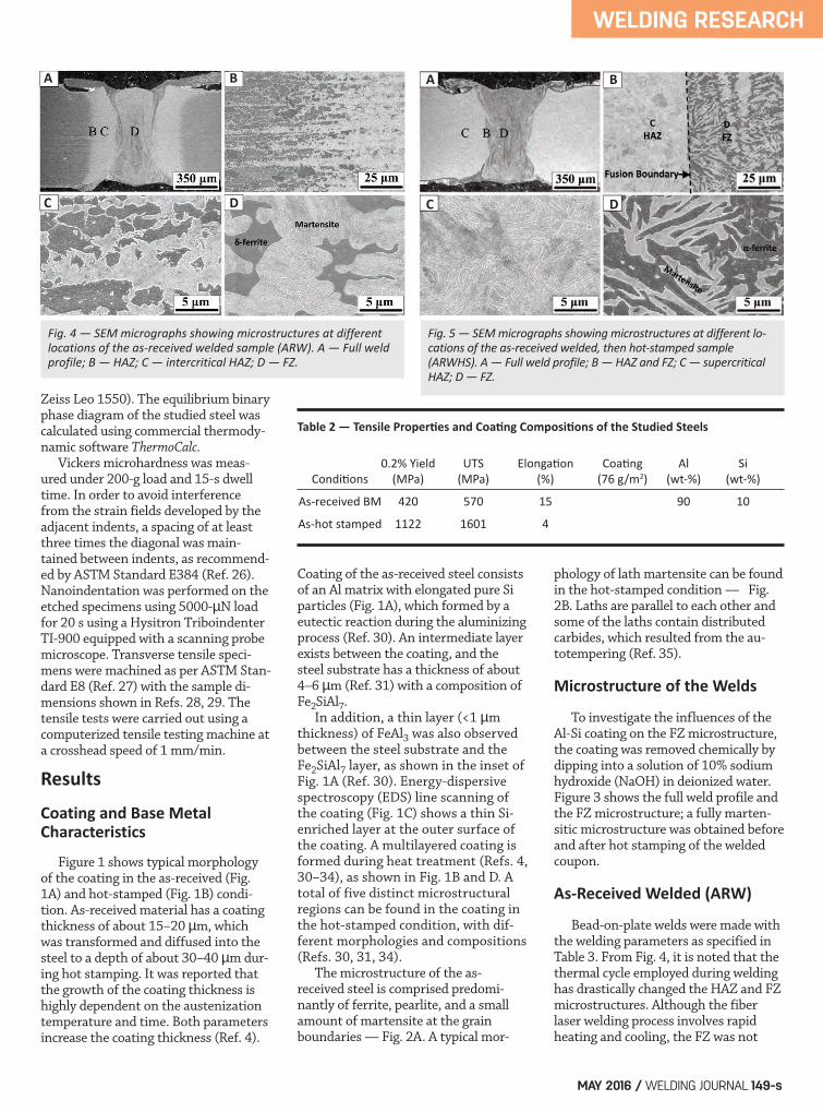
Fig. 4 — SEM micrographs showing microstructures at differentlocations of the asreceived welded sample (ARW). A — Full weldprofile; B — HAZ; C — intercritical HAZ; D — FZ.
Fig. 5 — SEM micrographs showing microstructures at different locations of the asreceived welded, then hotstamped sample(ARWHS). A — Full weld profile; B — HAZ and FZ; C — supercriticalHAZ; D — FZ.
Table 2 — Tensile Properties and Coating Compositions of the Studied Steels
0.2% Yield UTS Elongation Coating Al Si Conditions (MPa) (MPa) (%) (76 g/m2) (wt%) (wt%)
Asreceived BM 420 570 15 90 10
Ashot stamped 1122 1601 4
A AB B
C CD D
Saha 5-16.qxp_Layout 1 4/14/16 6:18 PM Page 149

transformed to complete martensitedue to mixing of the coating into theFZ. The FZ microstructure in the coatedsheet is a combination of skeletal ferriteand martensite (Fig. 4D), and the areafraction of ferrite and martensite (usingImageJ software) (Ref. 36) was estimat-ed to be about 20 and 80%, respectively.It has been reported that the skeletalpattern ferrite is a typical structure ofhigh-temperature delta-ferrite (d-fer-rite) (Refs. 37, 38); therefore, the ferrite
structure found on the ARW sample canbe referred to as d-ferrite. From the so-lidification pattern, it can be presumedthe d-ferrite phase was solidified as thefirst solidified phase; afterward, themartensite phase appeared. The influ-ence of the coating on the FZ mi-crostructure modification is discussedlater. The BM contains only ferrite andpearlite, which are already softer thanthe martensite in the FZ; therefore, noheat-affected zone (HAZ) softening was
detected. However, the HAZ of theARW sample consists of retransformedmartensite and ferrite (Fig. 4C) wherethe peak temperature during weldingwas between the Ac1 and Ac3 tempera-tures of the steel.
AsReceived Welded then HotStamped (ARWHS)
The as-received material was weld-ed using similar welding parameters asused for ARW sample (Table 3). Thewelded coupons were then austenizedand quenched between dies, which re-sulted in the microstructures shown inFig. 5. It can be noted that after hotstamping, the HAZ microstructure iscompletely transformed to martensitesimilar to the hot-stamped BM; there-fore, identical microhardness can beexpected, since the microhardness isdependent on martensite fraction. It is suggested that the hot stamp-
WELDING RESEARCH
WELDING JOURNAL / MAY 2016, VOL. 95150-s
Fig. 6 — SEM micrographs showing microstructures at differentlocations of the hotstamped welded sample (HSW). A — Fullweld profile; B — HAZ; C — subcritical HAZ; D — FZ.
Fig. 7 — SEM micrographs showing AlSi coating mixing and resultant microstructures at various locations of the ARW sample.
Fig. 8 — SEM micrographs showing AlSi coating mixing and resultant microstructures at various locations of the ARWHS sample.
Fig. 9 — AlSi coating mixing in the fusion boundary of the HSWsample shows continuous networklike δferrite.
Table 3 — Materials, Hot Stamping Conditions, and Welding Parameters Used in This Study
Power Focal Length Spot Size Speed Conditions (kW) (mm) (mm) (m/min) Stamping Conditions ARW 4 200 0.6 12 Asreceived welded ARWHS 4 200 0.6 12 Asreceived welded then hot stampd HSW 4 200 0.6 12 Hotstamped welded
A
A
B
B
C
C
D
D
A B
C D
A B
C D
Saha 5-16.qxp_Layout 1 4/14/16 6:18 PM Page 150

ing process could not transform thesteel into a fully martensite structuredue to the mixing of the coating alloyinto the FZ. The FZ microstructurewas found to be a combination of fer-rite and martensite. The peak temper-ature (930°C) in the hot-stampingprocess is identical to the intercriticalHAZ temperature (between Ac1 andAc3); therefore, during hot stamping,the d-ferrite and martensite structurecan transform to ferrite (a-ferrite) andaustenite (g). This would explain theferrite phase observed in the FZ of theARWHS sample, which can be referredto as a-ferrite. This will be discussedin a later section. The area fraction ofthe a-ferrite and martensite were esti-mated to be about 40 and 60%, respec-tively, compared to 20% d-ferrite, and80% martensite in the ARW condition— Fig. 4D.
HotStamped Welded (HSW)
Unless coating mixing occurs at thefusion boundary, the FZ is also com-posed of 100% martensite, which has asimilar BM lath microstructure — Fig.6D. However, the martensite laths areclearly thinner and finer in the FZ,which suggests the cooling rate wasmuch faster during welding. The HAZmicrostructure can be divided intothree distinct zones termed as subcriti-cal HAZ, intercritical HAZ, and super-critical HAZ, depending on the temper-ature ranges. Among these zones, thesubcritical HAZ (Fig. 6C) experiencedtemperatures between room tempera-ture and the Ac1 temperature, such thatthe BM martensite structure under-went tempering. During tempering, themartensite structure is decomposed toferrite and cementite (Fe3C), which has
a lower strength compared to a fullymartensite structure (Refs. 39–42),which degrades the tensile, fatigue, andformability behavior of the weldedjoints (Refs. 23, 28, 29). The next zone is the intercriticalHAZ, where partial austenization oc-curred between the temperatures of Ac1and Ac3 line. The microstructure wasfound to be a combination of ferrite andretransformed martensite — Fig. 6B. Asthe temperature increased in the HAZ,the fraction of martensite increased aswell, thereby improving the mechanicalproperties in contrast to the subcriticalHAZ. When the local peak temperatureduring welding exceeds the Ac3 temper-ature, the microstructure becomes fullymartensitic (with the highest micro-hardness) and is therefore referred to asthe supercritical HAZ. The FZ structurewas found to be fully martensitic,whereas the fusion boundary mi-crostructure is composed of martensiteand a network of d-ferrite phase. During laser beam welding, a highervapor pressure pushed away the moltenmetal from the keyhole center (Ref. 43)and the weld metal mixed with the Al-Sicoating generated a vortex flow at theupper sides of the molten pool. There-fore, due to limited solubility of the hot-stamped coating to the weld pool, thecoating was not mixed with the moltenmetal homogeneously. Consequently,the local Al concentration was higher atthe fusion boundary, which stabilizesthe high-temperature ferrite phase (d-ferrite) during rapid solidification.
Coating Mixing into the Fusion Zone
In the current studies, it was foundthat the presence of an Al-Si coating in-fluences the formation of d-ferritephase in the FZ (Figs. 4–6), since no evi-dence of d-ferrite was observed in thewelded sample where this coating was
WELDING RESEARCH
MAY 2016 / WELDING JOURNAL 151-s
Fig. 10 — EDS line scanning results of Al and Si across the martensite and ferrite phase. Aand B — center of the FZ in the ARW sample; C and D — center of the FZ in the ARWHSsample; E and F — the fusion boundary in the HSW sample.
Table 4 — Average Al and Si wt% in Ferrite Phase for Three Different Sample Conditions
Conditions Al (wt%) Si(wt%)
ARW 2.52 � 0.08 0.71 � 0.07
ARWHS 1.70 � 0.21 0.67 � 0.10
HSW 2.64 � 0.23 0.60 �0.13
A B
E F
C D
Saha 5-16.qxp_Layout 1 4/14/16 6:18 PM Page 151

chemically removed — Fig. 3. It wasalso observed that the presence of thecoating on either surface may be mixedinto the FZ; however, a coating on thetop surface of the sheet has the mostprominent effect on the d-ferrite forma-tion. Coating mixing was most notice-able along the fusion boundary, whered-ferrite was formed as a continuousstructure due to the effect of Marangoniconvection flow (Refs. 44, 45). Figures 7 and 8 distinguish thecoating mixing and resultant mi-crostructure among the ARW and AR-WHS conditions. Although both of theFZ consist of a ferrite (d-ferrite or a-ferrite) and martensite structure, themartensite fraction is clearly higher inthe ARW condition (about 80%). It isworth mentioning here that the higherfraction of martensite is associatedwith higher heating parameters, i.e.,temperature and time, during hotstamping, as reported by Kang et al.(Ref. 19). Their calculation shows thatwhen the Al and Si content increases,the ferrite to austenite phase transfor-mation temperature also increases. Martensite formed in the FZ of theARW sample resulted from the higheraustenization temperature and rapidcooling (~10,000°C/s (Refs. 23, 46))during welding, whereas the ARWHSspecimen showed a decreased fractionof the martensite (about 40%) becauseof the lower austenization tempera-ture (930°C) and slower cooling rate(~31°C/s) in the hot-stamping process.Another distinguishable feature is that
samples in the ARW condition containa larger fraction of d-ferrite along thefusion boundary (Fig. 7D); conversely,a uniform distribution of the a-ferriteand martensite can be identifiedthroughout the FZ of the ARWHSsample — Fig. 8D. Unlike the above two cases, theHSW condition exhibits coating mix-ing only along the fusion boundary —Fig. 9. There is no trace of d-ferrite atthe center of the FZ, where the mi-crostructure was fully martensite witha high microhardness (505 ± 23 HV). Ahigher fraction of localized d-ferrite atthe fusion boundary indicates thatthere was limited mixing of the coat-ing in the weld pool. As a result, the lo-cal concentration of Al at the fusionboundary was higher compared to thecenter area of the FZ. The d-ferritephase at fusion boundary was found tohave a skeletal-like continuous struc-
ture (Fig. 9C and D) rather than agrain-like structure — Fig. 8D. The compositional analysis of themartensite and ferrite phase was per-formed using the EDS line scanningtechnique as presented in Fig. 10. In ad-dition, the chemical composition ofeach phase was measured (Table 4); theresult shows rich Al content (1.70 to2.64 wt-%) in the ferrite phase. The in-fluence of Al content on phase transfor-mation and d-ferrite formation is pre-dicted using a ThermoCalc Fe-Al binaryphase diagram (Fig. 11), and is dis-cussed later. However, Si content wasfound to be at the same level in all threedifferent sample conditions.
Mechanical Properties
Hardness
Nanohardness of the individual
WELDING RESEARCH
WELDING JOURNAL / MAY 2016, VOL. 95152-s
Fig. 11 — ThermoCalc binary phase diagrams of FeAl and illustrated influence of Al on the phase transformation and δferrite formation.
Fig. 13 — Microhardness distributions across the weldment. A — ARW and ARWHS samples; B — HSW sample. Error bars represent the standard deviation.
Fig. 12 — Nanoindentation study of the different phases presentin the weldment. A — The ARW sample; B — the ARWHS sample; C — the HSW sample; D — the comparison of thenanohardness among the samples. Error bars represent thestandard deviation.
A
A
B
B
C D
Saha 5-16.qxp_Layout 1 4/14/16 6:18 PM Page 152
phases of martensite, and ferrite (d-ferrite and a-ferrite) were further esti-mated by using instrumented nanoin-dentation tests. The indent impres-sions from individual grains on eachphase in three different samples arepresented in Fig. 12. A total of 12 to16 indents were made on each phase,i.e., on martensite and ferrite in theFZ (ARW and AWRHS sample) and thefusion boundary (HSW sample). Theaverage nanohardness of the marten-site and ferrite phase ranges from 7.1to 7.9 GPa and 4.5 to 4.9 GPa, respec-tively, for all three sample conditions. Hardness impression on the marten-site islands of the ARWHS sample ex-hibit the lowest nanohardness (7.1 ± 0.6GPa) among the martensite phases onthe two other samples, which is due tothe lower cooling rate in the hot-stamp-ing process and smaller stress-freemartensite grain. Conversely, nanohard-ness measured on the ferrite phase isfairly in the same range, which indicatesthat the strength of the ferrite phasewas not influenced by the hot-stampingprocess. It should be concluded that thesecond phase found in the FZ of all ma-terial conditions definitely was not con-sistent with the hardness of an inter-metallic compound as reported in earli-er literature (Refs. 13, 17, 18). Thenanohardness of the intermetallic com-pound phase (Fe (Al, Si), Fig. 1B) ismuch higher (10.1 ± 0.5 GPa) comparedto the hardness of ferrite (4.1–4.9 GPa)phase. The microhardness distributions
across the three different welded sam-ples are presented in Fig. 13. The as-received and hot-stamped BM hardnessvalues are about 244 ± 4, and 575 ± 8HV, respectively. Hardness profiles ob-tained from the ARW and HSW condi-tions exhibited the maximum hardnessin the supercritical HAZ, which was dueto the solid-state transformation, rapidcooling, and a larger fraction of themartensite phase compared to other lo-cations. Although there are significantdifferences in hardness among the as-received and hot-stamped steels, the av-erage FZ hardness of the ARW andHSW samples were similar, about 516 ±25 and 505 ± 23 HV, respectively. A larger deviation of the hardnessin the FZ was believed to be the effectof the coating mixing in the fusionboundary. For instance, the circularmarked point on the hardness profileof the HSW sample (Fig. 13B) indi-cates the fusion boundary, where thereis a higher fraction of network-like d-ferrite — Fig. 9C. The average micro-and nanohardness of the fusionboundary and ferrite were measuredto be about 404 ± 63 HV and 4.5 ± 0.1GPa, respectively. Unlike the HAZ ofthe ARW condition, the HAZ of theHSW sample undergoes tempering be-cause of the martensite microstruc-ture present in its BM. It has been re-ported that tempering of martensitehas reduced the strength of the jointin all types of welding processes (Refs.23, 28, 29). In this study, it was found that the
HAZ hardness was reduced by about35% (from 575 ± 8 HV (BM) to 374 ±25 HV (HAZ)) compared to the hot-stamped BM hardness. Similar soften-ing was reported by Jia et al. (Ref. 47)in hot-stamped welded 22MnB5 steel.In addition, they also found that withincreasing welding speed, the HAZ andFZ hardness increases due to lowerheat input. While comparing hardnessdistribution of the ARWHS samplewith other conditions, there is no soft-ening or variation of the hardness be-tween BM and HAZ. Conversely, asharp drop in hardness was measuredin the FZ (Fig. 13A); the BM hardnesswas 575 ± 8 HV, which decreased to394 ± 24 HV, representing about a32% reduction of hardness, in contrastto the BM and HAZ. The degree ofsoftening in the FZ of the ARWHSsample was the same as that observeddue to the HAZ softening in the HSWsample — Fig. 13B.
Tensile Properties andFailure Locations
Typical engineering stress vs. straincurves of the BMs and three differentwelded samples are presented in Fig.14. The corresponding mechanicalproperties and the failure macro-graphs of the joints can be found inTable 5 and Fig. 15, respectively. The hot-stamped BM (HSBM) showsthe highest yield strength (1122 MPa)and ultimate tensile strength (1601MPa), which can be expected from the
WELDING RESEARCH
MAY 2016 / WELDING JOURNAL 153-s
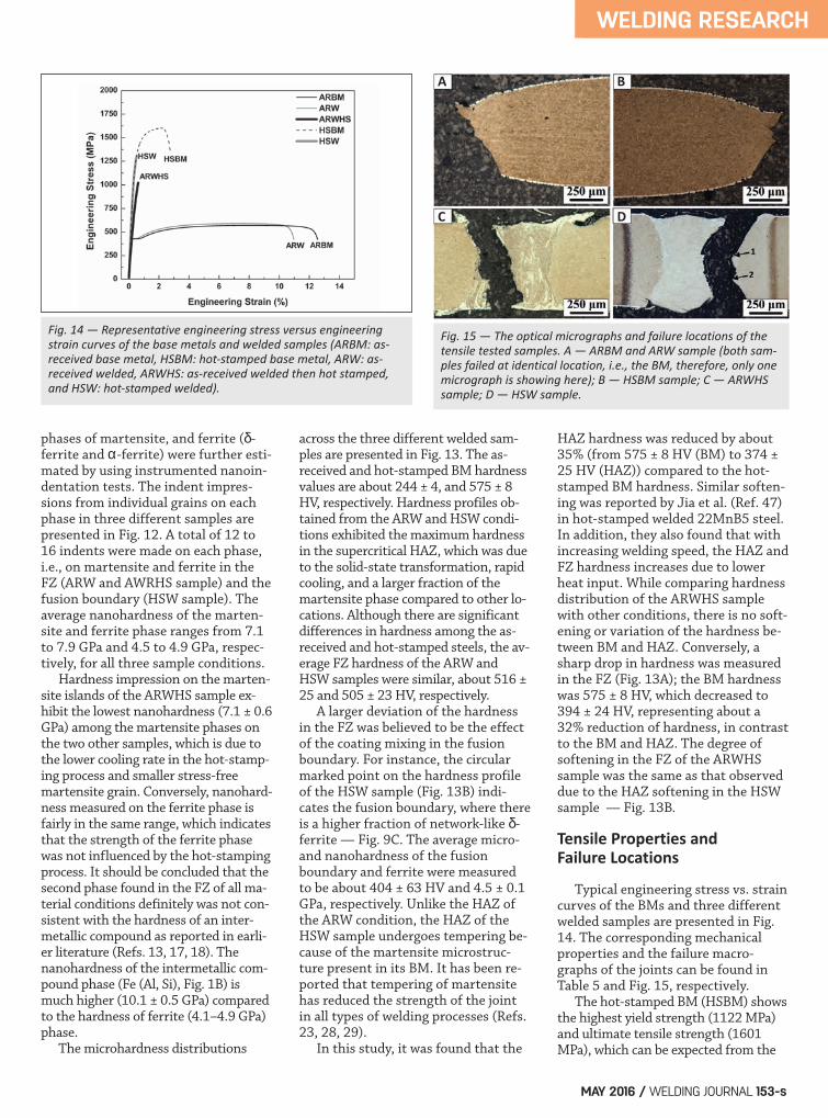
Fig. 14 — Representative engineering stress versus engineeringstrain curves of the base metals and welded samples (ARBM: asreceived base metal, HSBM: hotstamped base metal, ARW: asreceived welded, ARWHS: asreceived welded then hot stamped,and HSW: hotstamped welded).
Fig. 15 — The optical micrographs and failure locations of thetensile tested samples. A — ARBM and ARW sample (both samples failed at identical location, i.e., the BM, therefore, only onemicrograph is showing here); B — HSBM sample; C — ARWHSsample; D — HSW sample.
A B
C D
Saha 5-16.qxp_Layout 1 4/14/16 6:18 PM Page 153
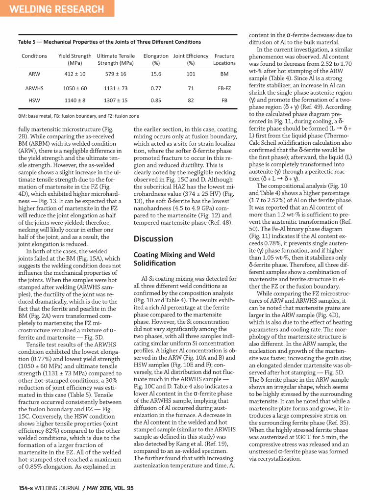
fully martensitic microstructure (Fig.2B). While comparing the as-receivedBM (ARBM) with its welded condition(ARW), there is a negligible difference inthe yield strength and the ultimate ten-sile strength. However, the as-weldedsample shows a slight increase in the ul-timate tensile strength due to the for-mation of martensite in the FZ (Fig.4D), which exhibited higher microhard-ness — Fig. 13. It can be expected that ahigher fraction of martensite in the FZwill reduce the joint elongation as halfof the joints were yielded; therefore,necking will likely occur in either onehalf of the joint, and as a result, thejoint elongation is reduced. In both of the cases, the weldedjoints failed at the BM (Fig. 15A), whichsuggests the welding condition does notinfluence the mechanical properties ofthe joints. When the samples were hotstamped after welding (ARWHS sam-ples), the ductility of the joint was re-duced dramatically, which is due to thefact that the ferrite and pearlite in theBM (Fig. 2A) were transformed com-pletely to martensite; the FZ mi-crostructure remained a mixture of a-ferrite and martensite — Fig. 5D. Tensile test results of the ARWHScondition exhibited the lowest elonga-tion (0.77%) and lowest yield strength(1050 ± 60 MPa) and ultimate tensilestrength (1131 ± 73 MPa) compared toother hot-stamped conditions; a 30%reduction of joint efficiency was esti-mated in this case (Table 5). Tensilefracture occurred consistently betweenthe fusion boundary and FZ — Fig.15C. Conversely, the HSW conditionshows higher tensile properties (jointefficiency 82%) compared to the otherwelded conditions, which is due to theformation of a larger fraction ofmartensite in the FZ. All of the weldedhot-stamped steel reached a maximumof 0.85% elongation. As explained in
the earlier section, in this case, coatingmixing occurs only at fusion boundary,which acted as a site for strain localiza-tion, where the softer d-ferrite phasepromoted fracture to occur in this re-gion and reduced ductility. This isclearly noted by the negligible neckingobserved in Fig. 15C and D. Althoughthe subcritical HAZ has the lowest mi-crohardness value (374 ± 25 HV) (Fig.13), the soft d-ferrite has the lowestnanohardness (4.5 to 4.9 GPa) com-pared to the martensite (Fig. 12) andtempered martensite phase (Ref. 48).
Discussion
Coating Mixing and Weld Solidification
Al-Si coating mixing was detected forall three different weld conditions asconfirmed by the composition analysis(Fig. 10 and Table 4). The results exhib-ited a rich Al percentage at the ferritephase compared to the martensitephase. However, the Si concentrationdid not vary significantly among thetwo phases, with all three samples indi-cating similar uniform Si concentrationprofiles. A higher Al concentration is ob-served in the ARW (Fig. 10A and B) andHSW samples (Fig. 10E and F); con-versely, the Al distribution did not fluc-tuate much in the ARWHS sample —Fig. 10C and D. Table 4 also indicates alower Al content in the a-ferrite phaseof the ARWHS sample, implying thatdiffusion of Al occurred during aust-enization in the furnace. A decrease inthe Al content in the welded and hotstamped sample (similar to the ARWHSsample as defined in this study) wasalso detected by Kang et al. (Ref. 19),compared to an as-welded specimen.The further found that with increasingaustenization temperature and time, Al
content in the a-ferrite decreases due todiffusion of Al to the bulk material. In the current investigation, a similarphenomenon was observed. Al contentwas found to decrease from 2.52 to 1.70wt-% after hot stamping of the ARWsample (Table 4). Since Al is a strongferrite stabilizer, an increase in Al canshrink the single-phase austenite region(g) and promote the formation of a two-phase region (d + g) (Ref. 49). Accordingto the calculated phase diagram pre-sented in Fig. 11, during cooling, a d-ferrite phase should be formed (L → d +L) first from the liquid phase (Thermo-Calc Scheil solidification calculation alsoconfirmed that the d-ferrite would bethe first phase); afterward, the liquid (L)phase is completely transformed intoaustenite (g) through a peritectic reac-tion (d + L → d + g). The compositional analysis (Fig. 10and Table 4) shows a higher percentage(1.7 to 2.52%) of Al on the ferrite phase.It was reported that an Al content ofmore than 1.2 wt-% is sufficient to pre-vent the austenitic transformation (Ref.50). The Fe-Al binary phase diagram(Fig. 11) indicates if the Al content ex-ceeds 0.78%, it prevents single austen-ite (g) phase formation, and if higherthan 1.05 wt-%, then it stabilizes onlyd-ferrite phase. Therefore, all three dif-ferent samples show a combination ofmartensite and ferrite structure in ei-ther the FZ or the fusion boundary. While comparing the FZ microstruc-tures of ARW and ARWHS samples, itcan be noted that martensite grains arelarger in the ARW sample (Fig. 4D),which is also due to the effect of heatingparameters and cooling rate. The mor-phology of the martensite structure isalso different. In the ARW sample, thenucleation and growth of the marten-site was faster, increasing the grain size;an elongated slender martensite was ob-served after hot stamping — Fig. 5D.The d-ferrite phase in the ARW sampleshows an irregular shape, which seemsto be highly stressed by the surroundingmartensite. It can be noted that while amartensite plate forms and grows, it in-troduces a large compressive stress onthe surrounding ferrite phase (Ref. 35).When the highly stressed ferrite phasewas austenized at 930°C for 5 min, thecompressive stress was released and anunstressed a-ferrite phase was formedvia recrystallization.
WELDING RESEARCH
WELDING JOURNAL / MAY 2016, VOL. 95154-s
Table 5 — Mechanical Properties of the Joints of Three Different Conditions
Conditions Yield Strength Ultimate Tensile Elongation Joint Efficiency Fracture (MPa) Strength (MPa) (%) (%) Locations
ARW 412 ± 10 579 ± 16 15.6 101 BM ARWHS 1050 ± 60 1131 ± 73 0.77 71 FBFZ
HSW 1140 ± 8 1307 ± 15 0.85 82 FB
BM: base metal, FB: fusion boundary, and FZ: fusion zone
Saha 5-16.qxp_Layout 1 4/15/16 3:04 PM Page 154
StructureProperty Correlation
This section will deal with the hot-stamped version of the steels, i.e., AR-WHS and HSW specimens. In bothcases, the minimum hardness was esti-mated to be at the FZ and subcriticalHAZ, respectively. It was also observedthat hardness degraded in a similaramount (ARWHS: 32% and HSW:35%) in contrast to the BM — Fig. 13.In addition, hardness also dropped atthe fusion boundary due to coatingmixing and formation of d-ferrite,which accounts for a 30% reduction ofthe hardness compared to the BM. Inaddition to concavity, which acts as aphysical crack initiation zone, thelarge variation of hardness betweenthe HAZ and FZ will effectively pro-vide a metallurgical notch during ten-sile tests. It was interesting to observethat failure did not occur at the sub-critical HAZ where the highest hard-ness drop (35%) was measured, butrather the origin of failure occurred atthe fusion boundary. This is a result ofthe continuous network structure ofthe fusion boundary d-ferrite, whichintroduces a larger metallurgical notchand promotes failure. Therefore, the HSW sample experi-ences failure along the fusion boundaryand leaves the FZ completely intact. Asin the HSW sample, the Al-Si coatingmixing predominantly occurred on thetop surface and extended to half of thesheet thickness; therefore, it can be sug-gested that half of the weld thicknesswas fractured along the soft d-ferrite assuggested by the fracture path (point 1,Fig. 15D) and the other half failed bytearing of the martensite phase (point2, Fig. 15D) due to stress localization. In contrast, tensile tests of the AR-WHS sample show failure occurred pre-dominantly at the FZ. The fracture initi-ated at the top surface of the fusionboundary and propagated through theFZ —Fig. 15C. As expected, the largerhardness drop at the fusion boundarypromoted stress localization. Therefore,it can be noted that the failure of thelaser-welded Al-Si hot-stamped steel isdependent on the presence of d-ferritein the FZ microstructures.
Conclusions The microstructure and the mechan-ical properties of fiber laser-welded PHS
were characterized considering the ef-fect of Al-Si coating mixing in the weldpool. The coating mixing role on weldsolidification was examined and the ma-jor findings of this study can be summa-rized as follows:
1) The FZ microstructure was modi-fied due to the effect of coating mixing.Significant coating mixing occurred inthe FZ of the ARW sample, andpromoted d-ferrite formation.Therefore, the FZ microstructure wasfound to be a combination of d-ferriteand martensite. Conversely, the HSWsample indicates a continuous network-like d-ferrite at the fusion boundary,and a fully martensitic microstructurein the center of the FZ. 2) A higher percentage of Al prompt-ed ferrite formation. In addition, ferriteformation was also influenced by thehot stamping process. Lower coolingrate increases the ferrite formation;therefore, the fraction of martensitewas found to be decreased after hotstamping of the ARW sample (i.e., ARWHS sample). In this case, the FZmicrostructure is a combination of ×-ferrite and martensite. 3) Vickers microhardness andnanoindentation on the fusion bound-ary and ferrite revealed significantlylower hardness values, 404 ± 63 HVand 4.5 to 4.9 GPa, respectively, ascompared to other regions of the weld-ment. Likewise, the ferrite andmartensite dual phase structure showsthe lowest microhardness (about 394± 24 HV) at the FZ. 4) The strength of the fiber laser-welded PHS is dependent on the frac-tion of ferrite phase formation, themicrohardness decreased by about32% as a result of coating mixing andleading to failure across the FZ in theARWHS sample, whereas the HSWspecimen failed at the fusion bound-ary. Therefore, an insignificant effectof martensite tempering on the jointperformance was observed.
The authors would like to acknowl-edge AUTO21, Canada’s AutomotiveResearch and Development Program,NSERC, and Innovation in AutomotiveManufacturing Initiative (IAMI) inCanada for financing this project. Theauthors are also thankful to Arcelor-
Mittal Dofasco, Inc., in Hamilton,Canada, for providing the materials tocarry out this work. The authors wouldlike to thank Prof. Michael Worswickfrom the Mechanical and MechatronicsEngineering Department, University ofWaterloo, for the hot stamping facili-ties, and Dr. Yuquan Ding as well forhis kind cooperation with the nanoin-dentation study.
1. Karbasian, H., and Tekkaya A. E.2010. A review on hot stamping. Journal ofMaterials Processing Technology 210(15):2103–2118. 2. Drew, S., Greg, F., Michael, W., Susan,C. A., Rita Van, D., Nicholas, Z. M., Jeff, A.,Dorothy, K., and George, M. 2011. Climate,health, agricultural and economic impactsof tighter vehicle-emission standards. Na-ture Climate Change 1(1): 59–66. 3. Kim, H. J., McMillan, C., Keoleian, G.A., and Skerlos, S. J. 2010. Greenhouse gasemissions payback for lightweighted vehi-cles using aluminum and high-strengthsteel. Journal of Industrial Ecology 14(6):929–946. 4. Fan, D. W., and De Cooman, B. C.2012. State-of-the-knowledge on coatingsystems for hot stamped parts. Steel Re-search International 83(5): 412–433. 5. Yao, Y., Meng, J. P., Ma, L. Y., Zhao,G. Q., and Wang, L. R. 2013. Study on hotstamping and usibor 1500P. Applied Me-chanics and Materials 320: 419–425. 6. Kolleck, R., and Veit, R. 2010. Toolsand technologies for hot forming with lo-cal adjustment of part properties. Materi-als Science Forum 638-642: 3919–3924. 7. Saunders, F. I., and Wagoner, R. H.1996. Forming of tailor-welded blanks.Metallurgical and Materials Transactions A27(9): 2605–2616. 8. Chan, L. C., Cheng, C. H., Chan, S.M., Lee, T. C., and Chow, C. L. 2005.Formability analysis of tailor-weldedblanks of different thickness ratios. Jour-nal of Manufacturing Science and Engineer-ing 127(4): 743–751. 9. Min., K. B., and Kang, S. S. 2000. Astudy on resistance welding in steel sheetsfor tailor welded blank evaluation of flashweldability and formability (2nd Report).Journal of Materials Processing Technology103(2): 218–224. 10. Quintino, L., Costa, A., Miranda, R.,Yapp, D., Kumar, V., and Kong, C. J. 2007.Welding with high power fiber lasers — Apreliminary study. Materials & Design 28(4): 1231–1237. 11. Thomy, C., Seefeld, T., and Vollert-sen, F. 2005. High-power fibre lasers —
WELDING RESEARCH
MAY 2016 / WELDING JOURNAL 155-s
Acknowledgments
References
Saha 5-16.qxp_Layout 1 4/15/16 2:10 PM Page 155
Application potentials for welding of steeland aluminium sheet material. AdvancedMaterials Research 6-8: 171 to 178. 12. Westerbaan, D. 2013. Fiber laserwelding of advanced high strength steels.M. Sc. thesis. Waterloo, ON, University ofWaterloo. 13. Kim, C., Kang, M. J., and Park, Y. D.2011. Laser welding of Al-Si coated hotstamping steel. Procedia Engineering 10(0):2226–2231. 14. Moon, J. H., Seo, P. K., and Kang, C.G. 2013. A study on mechanical propertiesof laser-welded blank of a boron sheet steelby laser ablation variable of Al-Si coatinglayer. International Journal of Precision Engi-neering and Manufacturing 14(2): 283–288. 15. Kwon, M. S., Kim, Y. G., Kim, Y. J.,Kang, C. Y., Kong, J. P., Oh, M. H., Shin, H.J., and Oh, S. T. 2014. Tailor welded blank,manufacturing method thereof, and hotstamped component using tailor weldedblank. U.S. Patent 20140154521 A1. 16. Pic, A., Duque Múnera, D., andPinard, F. 2008. Press hardened steel basedlaser welded blanks: The ultimate tool forcrashworthiness. Metallurgical Research &Technology 105(01): 50–59. 17. Vierstraete, R., Ehling, W., Pinard,F., Cretteur, L., Pic, A., and Yin, Q. 2010.Laser ablation for hardening laser weldedsteel blanks. Industrial Laser Solutions25(2): 6. 18. Ehling, W., Cretteur, L., Pic, A.,Vierstraete, R., and Yin, Q. 2009. Proc. 5thInt. WLT Conf. Lasers Manuf., Munich, Germany. 19. Kang, M., Kim, Y. M., and Kim, C.2015. Effect of heating parameters on laserwelded tailored blanks of hot press form-ing steel. Journal of Materials ProcessingTechnology. 20. Kasuya, T., and Yurioka, N. 1993.Carbon equivalent and multiplying factorfor hardenability of steel. Welding Journal72(6): 263-s to 268-s. 21. Merklein, M., and Lechler, J. 2006.Investigation of the thermo-mechanicalproperties of hot stamping steels. Journalof Materials Processing Technology 177(1-3):452–455. 22. Bardelcik, A., Salisbury, C. P., Win-kler, S., Wells, M. A., and Worswick, M. J.2010. Effect of cooling rate on the highstrain rate properties of boron steel. Inter-national Journal of Impact Engineering37(6): 694–702. 23. Saha, D. C., Westerbaan, D., Nayak,S. S., Biro, E., Gerlich, A. P., and Zhou, Y.2014. Microstructure-properties correla-tion in fiber laser welding of dual-phaseand HSLA steels. Materials Science and En-gineering: A 607: 445–453. 24. General Motors Engineering Stan-dards. 2002. Weld Specifications LaserWelds-Butt Joints. GM4485M. 25. Westerbaan, D., Parkes, D., Nayak,
S. S., Chen, D. L., Biro, E., Goodwin, F., andZhou. Y. 2014. Effects of concavity on ten-sile and fatigue properties in fibre laserwelding of automotive steels. Science andTechnology of Welding and Joining 19(01):60–68. 26. ASTM Standard, E384-11E1. 2007.Standard test method for Knoop and Vick-ers hardness of materials. West Con-shohocken, Pa.: ASTM International. 27. ASTM Standard E8. 2011. Standardtest methods for tension testing of metal-lic materials. West Conshohocken, Pa.:ASTM International. 28. Xu, W., Westerbaan, D., Nayak, S.,Chen, D., Goodwin, F., Biro. E., and Zhou,Y. 2012. Microstructure and fatigue per-formance of single and multiple linearfiber laser welded DP980 dual-phase steel.Materials Science and Engineering: A 553:51–58. 29. Xu, W., Westerbaan, D., Nayak, S. S.,Chen, D. L., Goodwin, F., and Zhou, Y.2013. Tensile and fatigue properties offiber laser welded high strength low alloyand DP980 dual-phase steel joints. Materi-als & Design 43: 373–383. 30. Fan, D. W., Kim, H. S., Oh, J. K.,Chin, K. G., and De Cooman, B. C. 2010.Coating degradation in hot press forming.ISIJ International 50(4): 561–568. 31. Windmann, M., Röttger, A., andTheisen, W. 2014. Formation of inter-metallic phases in Al-coated hot-stamped22MnB5 sheets in terms of coating thick-ness and Si content. Surface and CoatingsTechnology 246: 17–25. 32. Drillet, P., Drillet, D., and Keffer-stein, R. 2009. Process for manufacturingstamped products, and stamped productsprepared from the same U.S. Patent8733142 B2. 33. Grauer, S. J., Caron, E. J. F. R.,Chester, N. L., Wells, M. A., and Daun, K. J.2015. Investigation of melting in the Al–Sicoating of a boron steel sheet by differentialscanning calorimetry. Journal of MaterialsProcessing Technology 216: 89–94. 34. Suehiro, M., Maki, J., Kusumi, K.,Ohgami, M., and Miyakoshi, T. 2003. Prop-erties of aluminum coated steels for hot-forming. Nippon Steel Technical Report:15–20. 35. Bhadeshia, H. K. D. H., and Honey-combe, R. W. K. 2011. Steels — Microstruc-ture and Properties. Butterworth-Heine-mann, Oxford, UK, Elsevier. 36. Rasband, W. S. 1997. ImageJ, Na-tional Institutes of Health, Bethesda, Md.0 38. Amirthalingam, M., Hermans, M.,and Richardson, I. 2009. Microstructuraldevelopment during welding of silicon-and aluminum-based transformation-in-duced plasticity steels — Inclusion and ele-mental partitioning analysis. Metallurgicaland Materials Transactions A 40(4):901–909.
39. Biro, E., Vignier, S., Kaczynski, C.,McDermid, J. R., Lucas, E., Embury, J. D.,and Zhou, Y. N. 2013. Predicting transientsoftening in the sub-critical heat-affectedzone of dual-phase and martensitic steelwelds. ISIJ International 53(1): 110–118. 40. Biro, E., McDermid, J., Embury, J.,and Zhou, Y. 2010. Softening kinetics inthe subcritical heat-affected zone of dual-phase steel welds. Metallurgical and Materi-als Transactions A 41(9): 2348–2356. 41. Xia, M., Biro, E., Tian, Z., and Zhou,Y. N. 2008. Effects of heat input andmartensite on HAZ softening in laser weld-ing of dual phase steels. ISIJ International48(6): 809–814. 42. Baltazar Hernandez, V. H., Nayak, S.S., and Zhou, Y. 2011. Tempering ofmartensite in dual-phase steels and its ef-fects on softening behavior. Metallurgicaland Materials Transactions A 42(10):3115–3129. 43. Mickael, C., Muriel, C., Philippe Le,M., Sadok, G., and Mikhaël, B. 2013. A newapproach to compute multi-reflections oflaser beam in a keyhole for heat transferand fluid flow modelling in laser welding.Journal of Physics D: Applied Physics 46(50):505305. 44. Limmaneevichitr, C., and Kou, S.2000. Visualization of Marangoni convec-tion in simulated weld pools. Welding Journal79(5): 126-s to 135-s. 45. Limmaneevichitr, C., and Kou, S.2000. Experiments to simulate effect ofMarangoni convection on weld pool shape.Welding Journal 79(8): 231-s to 237-s. 46. Gould, J., Khurana, S., and Li, T.2006. Predictions of microstructures whenwelding automotive advanced high-strength steels. Welding Journal 85(5): 111-s to 116-s. 47. Jia, J., Yang, S. L., Ni, W. Y., Bai, J.Y., and Lin, Y. S. 2014. Microstructure andproperties of fiber laser welded joints of ul-trahigh-strength steel 22MnB5 and its dis-similar combination with Q235 Steel. ISIJInternational 54(12): 2881 to 2889. 48. Baltazar Hernandez, V. H., Panda, S.K., Kuntz, M. I., and Zhou, Y. 2010.Nanoindentation and microstructureanalysis of resistance spot welded dualphase steel. Materials Letters 64(2):207–210. 49. San Martín, D., Palizdar, Y., García-Mateo, C., Cochrane, R. C., Brydson, R.,and Scott, A. J. 2011. Influence of alu-minum alloying and heating rate onaustenite formation in low carbon-man-ganese steels. Metallurgical and MaterialsTransactions A 42(9): 2591–2608. 50. Briand, F., Dubet, O., and Choet, C.2011. Process for Laser-ARC Hybrid Weld-ing Aluminized Metal Workpieces. U.S.Patent 20110226746 A1.
WELDING RESEARCH
WELDING JOURNAL / MAY 2016, VOL. 95156-s
Saha 5-16.qxp_Layout 1 4/14/16 6:18 PM Page 156