fhwa micropile design and construction - earth engineers micropile design and construction - earth...
TRANSCRIPT

U.S. Department of Transportation Publication No. FHWA NHI-05-039 Federal Highway Administration December 2005 NHI Course No. 132078_______________________________
Micropile Design and Construction Reference Manual
ROAD SURFACEFINISHED GRADE
SLIDE PLANE
CONCRETE CAP
CASE 1NON RETICULATEDMICROPILE STRUCTURE
NEW BRIDGE STRUCTURE
BRIDGE ABUTMENT
NEW MICROPILEFOUNDATION SUPPORT(TYP)
SURCHARGE
FINAL GRADE
CONCRETE CAP
CASE 2 RETICULATEDMICROPILE WALL
ORIGINALGRADE
SECTION A – A
EXISTINGFOOTING & PILES
EXISTING DRIVENPIPE PILES (TYP)
NEW FOOTINGEXTENSION
EXISTING BRIDGEPIER W/PILESUPPORTEDFOOTING
NEW MICROPILES
A
NEW MICROPILES
FOUNDATION SUPPORT
SLOPE STABILIZATION
SEISMIC RETROFIT OF BRIDGES
EARTH RETENTION
WALL FACING
National Highway Institute

NOTICE The contents of this report reflect the views of the authors, who are responsible for
the facts and the accuracy of the data presented herein. The contents do not necessarily reflect policy of the Department of Transportation. This report does not constitute a standard, specification, or regulation. The United States Government
does not endorse products or manufacturers. Trade or manufacturer's names appear herein only because they are considered essential to the objective of this
document.

Technical Report Documentation Page 1. REPORT NO. FHWA-NHI-05-039
2. GOVERNMENT ACCESSION NO.
3. RECIPIENT'S CATALOG NO.
5. REPORT DATE
December 2005
4. TITLE AND SUBTITLE Micropile Design and Construction (Reference Manual for NHI Course 132078)
6. PERFORMING ORGANIZATION CODE 8. PERFORMING ORGANIZATION REPORT NO. 7. AUTHOR(S)
Paul J. Sabatinia P.E., Ph.D.; Burak Tanyua Ph.D.; Tom Armourb P.E.; Paul Groneckb P.E.; and James Keeleyb P.E.
a GeoSyntec Consultants, Chicago, IL b DBM Contractors Inc. Federal Way, WA 10. WORK UNIT NO.
9. PERFORMING ORGANIZATION NAME AND ADDRESS Ryan R. Berg & Associates, Inc. 2190 Leyland Alcove Woodbury, MN 55125 IN COOPERATION AND ASSOCIATION WITH: ADSC – The International Association of Foundation Drilling 14180 Dallas Parkway, Suite 510 Dallas, TX 75254
11. CONTRACT OR GRANT NO.
DTFH61-03-T-63043
13. TYPE OF REPORT & PERIOD COVERED
12. SPONSORING AGENCY NAME AND ADDRESS National Highway Institute Federal Highway Administration U.S. Department of Transportation Washington, D.C.
14. SPONSORING AGENCY CODE
15. SUPPLEMENTARY NOTES FHWA COTR – Larry Jones FHWA Technical Consultants: Jerry A. DiMaggio, P.E. and Barry Siel, P.E. This manual is an updated and revised version of FHWA SA-97-070 prepared by DBM Contractors Inc. and authored by T. Armour, P. Groneck, J. Keeley and S. Sharma; June 2000. 16. ABSTRACT The use of micropiles has grown significantly since their conception in the 1950s, and in particular since the mid-1980s. Micropiles have been used mainly as foundation support elements to resist static and seismic loads, and to a lesser extent, as in-situ reinforcements to provide stabilization of slopes and excavations. Many of these applications are for transportation structures. This manual is intended to be a “practitioner-oriented” document containing sufficient information on the geotechnical and structural design of micropiles for foundation support and for slope stabilization. Information is also provided on inspection and load testing procedures, cost data, and contracting methods to facilitate the safe and cost-effective use of micropiles on transportation projects. Two detailed design examples and a generic commentary guideline specification for micropiles is included in the manual. 17. KEY WORDS Micropiles, structural foundation, load testing, slope stabilization
18. DISTRIBUTION STATEMENT No restrictions.
19. SECURITY CLASSIF. Unclassified
20. SECURITY CLASSIF. Unclassified
21. NO. OF PAGES 436
22. PRICE

SI CONVERSION FACTORS APPROXIMATE CONVERSIONS FROM SI UNITS
Symbol When You Know Multiply By To Find Symbol
LENGTH mm m m km
millimeters meters meters
kilometers
0.039 3.28 1.09 0.621
inches feet
yards miles
in ft yd mi
AREA mm2 m2
m2 ha
km2
square millimeters square meters square meters
hectares square kilometers
0.0016 10.764 1.195 2.47 0.386
square inches square feet
square yards acres
square miles
in2 ft2 yd2 ac mi2
VOLUME ml l
m3 m3
millimeters liters
cubic meters cubic meters
0.034 0.264 35.71 1.307
fluid ounces gallons
cubic feet cubic yards
fl oz gal ft3 yd3
MASS g
kg tonnes
grams kilograms
tonnes
0.035 2.202 1.103
ounces pounds
tons
oz lb
tons TEMPERATURE
EC Celsius 1.8 C + 32 Fahrenheit EF WEIGHT DENSITY
kN/m3 kilonewton / cubic meter 6.36 poundforce / cubic foot pcf
FORCE and PRESSURE or STRESS N
kN kPa kPa
newtons kilonewtons kilopascals kilopascals
0.225 225
0.145 20.9
poundforce poundforce
poundforce / square inch poundforce / square foot
lbf lbf psi psf

FHWA NHI-05-039 Micropile Design & Construction i - iii December 2005
TABLE OF CONTENTS CHAPTER 1 INTRODUCTION 1.1 PURPOSE AND SCOPE OF MANUAL........................................................................ 1 – 1 1.2 MICROPILE DEFINITION AND DESCRIPTION ....................................................... 1 – 4 1.3 HISTORICAL BACKGROUND.................................................................................... 1 – 5 1.4 REFERENCES................................................................................................................ 1 – 8
CHAPTER 2 MICROPILE CLASSIFICATION SYSTEM 2.1 INTRODUCTION .......................................................................................................... 2 – 1 2.2 DESIGN APPLICATION CLASSIFICATION ............................................................. 2 – 1 2.3 CONSTRUCTION TYPE CLASSIFICATION.............................................................. 2 – 6 2.4 REFERENCES................................................................................................................ 2 – 8
CHAPTER 3 MICROPILE APPLICATIONS IN TRANSPORTATION PROJECTS 3.1 INTRODUCTION........................................................................................................... 3 – 1 3.2 FEASIBILITY OF MICROPILES.................................................................................. 3 – 1
3.2.1 Overview............................................................................................................ 3 – 1 3.2.2 Physical Considerations ..................................................................................... 3 – 3 3.2.3 Subsurface Conditions ....................................................................................... 3 – 4 3.2.4 Environmental Conditions ................................................................................. 3 – 4 3.2.5 Existing Structure Adaptation............................................................................ 3 – 6 3.2.6 Micropile Limitations ........................................................................................ 3 – 6 3.2.7 Economics of Micropiles ................................................................................... 3 – 6
3.3 STRUCTURAL SUPPORT ............................................................................................ 3 – 7 3.3.1 Overview............................................................................................................ 3 – 7 3.3.2 New Foundations ............................................................................................... 3 – 7 3.3.3 Underpinning of Existing Foundations.............................................................. 3 – 9 3.3.4 Seismic Retrofit ............................................................................................... 3 – 12
3.4 IN-SITU REINFORCEMENT...................................................................................... 3 – 14 3.5 REFERENCES.............................................................................................................. 3 – 20
CHAPTER 4 CONSTRUCTION TECHNIQUES AND MATERIALS 4.1 INTRODUCTION........................................................................................................... 4 – 1 4.2 DRILLING ...................................................................................................................... 4 – 1
4.2.1 Overview............................................................................................................ 4 – 1 4.2.2 Drill Rigs............................................................................................................ 4 – 3 4.2.3 Drilling Techniques ........................................................................................... 4 – 6 4.2.4 Overburden Drilling Techniques ....................................................................... 4 – 9 4.2.5 Open-Hole Drilling Techniques....................................................................... 4 – 13
4.3 GROUTING .................................................................................................................. 4 – 14 4.3.1 General............................................................................................................. 4 – 14 4.3.2 Grout Equipment ............................................................................................. 4 – 16 4.3.3 Grout Mixing ................................................................................................... 4 – 19 4.3.4 Grout Placement Techniques ........................................................................... 4 – 19
FHWA NHI-05-039 Micropile Design & Construction i-iv December 2005
4.3.4.1 Gravity Fill Techniques (Type A Micropiles)................................. 4 – 19 4.3.4.2 Pressure Grouting Through the Casing (Type B Micropiles) ......... 4 – 20 4.3.4.3 Postgrouting (Type C and D Micropiles) ........................................ 4 – 21
4.3.5 Top-Off (Secondary) Grouting ........................................................................ 4 – 26 4.4 REINFORCING STEEL ............................................................................................... 4 – 26
4.4.1 General............................................................................................................. 4 – 26 4.4.2 Placement of Reinforcement............................................................................ 4 – 26 4.4.3 Reinforcement Types ....................................................................................... 4 – 26
4.5 REFERENCES.............................................................................................................. 4 – 35 CHAPTER 5 DESIGN OF MICROPILES FOR STRUCTURE FOUNDATIONS 5.1 INTRODUCTION........................................................................................................... 5 – 1 5.2 STEP 1: EVALUATE FEASIBILITY OF MICROPILES ............................................ 5 – 3 5.3 STEP 2: REVIEW AVAILABLE INFORMATION & GEOTECHNICAL DATA ..... 5 – 5 5.4 STEP 3: DEVELOP APPLICABLE LOADING COMBINATIONS ........................... 5 – 7 5.5 STEP 4: PRELIMINARY DESIGN OF MICROPILES................................................ 5 – 8
5.5.1 Selection of Micropile Spacing.......................................................................... 5 – 8 5.5.2 Selection of Micropile Length ........................................................................... 5 – 8 5.5.3 Selection of Micropile Cross Section ................................................................ 5 – 9 5.5.4 Selection of Micropile Type ............................................................................ 5 – 10
5.6 STEP 5: STRUCTURAL DESIGN OF MICROPILE CASED LENGTH.................. 5 – 10 5.7 STEP 6: STRUCTURAL DESIGN OF MICROPILE UNCASED LENGTH ............ 5 – 17 5.8 STEP 7: REVISE MICROPILE DESIGN ................................................................... 5 – 18 5.9 STEP 8: EVALUATE GEOTECHNICAL CAPACITY OF MICROPILE................. 5 – 18
5.9.1 Establish Stratum for Bond Zone..................................................................... 5 – 18 5.9.2 Select Ultimate Bond Stress and Calculate Bond Length................................ 5 – 19 5.9.3 Evaluate Micropile Group Compression Capacity .......................................... 5 – 22 5.9.4 Evaluate Micropile Group Uplift Capacity...................................................... 5 – 27
5.10 STEP 9. ESTIMATE MICROPILE GROUP SETTLEMENT .................................. 5 – 29 5.10.1 General........................................................................................................... 5 – 29 5.10.2 Micropile Group Settlement .......................................................................... 5 – 29 5.10.3 Micropile Elastic Movement.......................................................................... 5 – 36
5.11 STEP 10. DESIGN MICROPILE CONNECTION AT PILE CAP........................... 5 – 38 5.12 STEP 11. DEVELOP LOAD TESTING PROGRAM............................................... 5 – 44 5.13 STEP 12. PREPARE DRAWINGS AND SPECIFICATIONS ................................. 5 – 45 5.14 CORROSION PROTECTION.................................................................................... 5 – 45
5.14.1 Background.................................................................................................... 5 – 45 5.14.2 Evaluation of Soil Corrosion Potential .......................................................... 5 – 46 5.14.3 Corrosion Protection Systems........................................................................ 5 – 46
5.14.3.1 Methods for Corrosion Protection of Reinforcing Steel ............... 5 – 46 5.14.3.2 Methods for Corrosion Protection of Steel Casing ....................... 5 – 48 5.14.3.3 Corrosion Protection Requirements for Micropiles ...................... 5 – 50
5.15 PLUNGE LENGTH..................................................................................................... 5 – 51 5.16 END BEARING MICROPILE.................................................................................... 5 – 52 5.17 DOWNDRAG.............................................................................................................. 5 – 53 5.18 DESIGN OF MICROPILES FOR LATERAL LOADING ........................................ 5 – 54
5.18.1 General........................................................................................................... 5 – 54

FHWA NHI-05-039 Micropile Design & Construction i - v December 2005
5.18.2 Analysis Steps for Single Laterally Loaded Micropile.................................. 5 – 54 5.18.3 Evaluation of Micropile Lateral Load Capacity at Threaded Casing Joints.. 5 – 60
5.19 LATERAL RESISTANCE OF MICROPILE GROUPS ............................................ 5 – 61 5.19.1 General........................................................................................................... 5 – 61 5.19.2 Step By Step Design Procedure for Laterally Loaded Pile Groups ............... 5 – 62 5.19.3 Soil-Structure Interaction Analyses for Micropile Groups............................ 5 – 66 5.19.4 Battered Micropiles........................................................................................ 5 – 66
5.20 BUCKLING CONSIDERATIONS FOR MICROPILES ........................................... 5 – 67 5.21.1 General........................................................................................................... 5 – 67 5.21.2 Micropile Surrounded by Very Weak or Liquefiable Soil............................. 5 – 67 5.20.3 Micropiles Installed Through Voids .............................................................. 5 – 72
5.21 SEISMIC CONSIDERATIONS.................................................................................. 5 – 73 5.21.1 General........................................................................................................... 5 – 73 5.21.2 Use of Battered Micropiles in Highly Seismic Regions ................................ 5 – 75 5.21.3 Load Sharing with Existing Foundations....................................................... 5 – 76 5.21.4 Pile Uplift Capacity........................................................................................ 5 – 77 5.21.5 Liquefaction ................................................................................................... 5 – 77
5.22 REFERENCES............................................................................................................ 5 – 79
CHAPTER 6 DESIGN OF MICROPILES FOR SOIL SLOPE STABILIZATION 6.1 INTRODUCTION........................................................................................................... 6 – 1 6.2 STEP 1: IDENTIFY PROJECT SPECIFIC CONSTRAINTS AND EVALUATE
MICROPILE FEASIBILITY....................................................................................... 6 – 3 6.3 STEP 2: IDENTIFY PERFORMANCE REQUIREMENTS......................................... 6 – 6 6.4 STEP 3: REVIEW AVAILABLE INFORMATION & GEOTECHNICAL DATA ..... 6 – 7 6.5 STEP 4: EVALUATE FACTOR OF SAFETY OF EXISTING SLOPE ...................... 6 – 9 6.6 DESIGN CONCEPTS FOR MICROPILES USED FOR SLOPE STABILIZATION 6 – 11
6.6.1 Overview.......................................................................................................... 6 – 11 6.6.2 Evaluating the Additional Force Required to Obtain Target Factor of Safety 6 – 12
6.6.2.1 Micropile Location Within Slope Cross Section .............................. 6 – 12 6.6.2.2 Methods to Model Resisting Force from a Micropile....................... 6 – 16 6.6.2.3 Evaluating Slope Stability Away From Micropile............................ 6 – 19
6.6.3 Load Transfer in Micropiles ............................................................................ 6 – 21 6.6.4 Bending Momemt and Shear Capacity of Single Vertical Micropile ............. 6 – 25
6.6.4.1 Evaluation of Bending Moment Capacity of Single Vertical Micropile ............................................................................................. 6 – 25
6.6.4.2 Evaluation of Shear Capacity of Single Vertical Micropile ............. 6 – 25 6.6.5 Shear Capacity of Battered Micropile Group .................................................. 6 – 30 6.6.6 Spacing Required to Provide Required Force to Stabilize the Slope.............. 6 – 33 6.6.7 Potential for Soil Flow Between Micropiles.................................................... 6 – 35
6.7 DESIGN EXAMPLES FOR SLOPE STABILIZATION WITH MICROPILES......... 6 – 37 6.7.1 STEP 4: Evaluate Factor of Safety of Existing Slope..................................... 6 – 39 6.7.2 STEP 5: Evaluate Additional Force Required to Obtain Target Factor of
Safety ............................................................................................................. 6 – 41 6.7.3 STEP 6: Select Micropile Cross Section ........................................................ 6 – 43 6.7.4 STEP 7: Estimate Length of Micropile........................................................... 6 – 44 6.7.5 STEP 8: Evaluate Bending Capacity of Single Vertical Micropile .............. 6 – 45

FHWA NHI-05-039 Micropile Design & Construction i-vi December 2005
6.7.6 STEP 9: Evaluate Shear Capacity of Single Vertical Micropile ................... 6 – 47 6.7.7 STEP 10: Evaluate Shear Capacity of Battered Micropile Group.................. 6 – 51 6.7.8 STEP 11: Calculate Spacing Required to Provide Force to Stabilize the
Slope................................................................................................................ 6 – 52 6.7.9 STEP 12: Check Potential Soil Flow between Micropiles ............................. 6 – 53 6.7.10 STEP 13: Perform Structural Design of Concrete Cap Beam ...................... 6 – 54
6.8 SHEAR CAPACITY OF MICROPILES FOR ANALYSIS ....................................... 6 – 58 6.9 CASE HISTORIES ....................................................................................................... 6 – 59
6.9.1 Stabilization of Blue Trail Landslide Using Micropiles, Wyoming ................ 6 – 59 6.9.2 Stabilization of Sum-271 Landslide Using Micropiles, Ohio ........................ 6 – 62 6.9.3 Stabilization of Littleville Landslide using Micropiles, Alabama ................... 6 – 66
6.10 REFERENCES............................................................................................................ 6 – 67 CHAPTER 7 PILE LOAD TESTING 7.1 INTRODUCTION............................................................................................................ 7 – 1 7.2 OVERVIEW OF MICROPILE LOAD TESTING .......................................................... 7 – 1 7.3 LOAD TESTING EQUIPMENT ..................................................................................... 7 – 3
7.3.1 General............................................................................................................... 7 – 3 7.3.2 Load Testing Equipment.................................................................................... 7 – 3
7.4 MICROPILE LOAD TESTING PROCEDURES.......................................................... 7 – 11 7.4.1 Verification Tests............................................................................................. 7 – 11
7.4.1.1 General ............................................................................................ 7 – 11 7.4.1.2 Procedures for Verification Test ..................................................... 7 – 11 7.4.1.3 Recording of Verification Test Data ............................................... 7 – 12
7.4.2 Proof Testing.................................................................................................... 7 – 15 7.4.2.1 General ............................................................................................ 7 – 15 7.4.2.2 Proof Test Procedures and Recording and Analysis of Proof Test
Data ............................................................................................ 7 – 15 7.4.3 Micropile Acceptance Criteria......................................................................... 7 – 15
7.4.3.1 Acceptance of Verification Test...................................................... 7 – 15 7.4.3.2 Acceptance of Proof Test ................................................................ 7 – 18 7.4.3.3 Consequences of Failure ................................................................. 7 – 18
7.5 MICROPILE LOAD TEST REPORT ........................................................................... 7 – 19 7.6 EVALUATION OF PROJECT LOAD TESTING REQUIREMENTS ........................ 7 – 20
7.6.1 Introduction...................................................................................................... 7 – 20 7.6.2 Load Testing Program for Verification Tests .................................................. 7 – 20
7.6.3 Load Testing Program for Proof Tests............................................................. 7 – 21 7.6.4 Test Load Magnitude ....................................................................................... 7 – 22 7.6.5 Method of Load Application............................................................................ 7 – 23
7.7 OTHER LOAD TESTING TECHNIQUES................................................................... 7 – 23 7.7.1 General............................................................................................................. 7 – 23 7.7.2 Dynamic Load Testing..................................................................................... 7 – 24
7.7.3 Statnamic Load Testing ................................................................................... 7 – 26 7.8 REFERENCES.............................................................................................................. 7 – 28
CHAPTER 8 CONSTRUCTION INSPECTION/QUALITY CONTROL 8.1 INTRODUCTION........................................................................................................... 8 – 1

FHWA NHI-05-039 Micropile Design & Construction i - vii December 2005
8.2 INSPECTION ROLES UNDER CERTAIN CONTRACT APPROACHES ................. 8 – 1 8.3 PRE-PROJECT PREPARATION................................................................................... 8 – 2 8.4 INSPECTION OF MICROPILE MATERIALS ............................................................. 8 – 5
8.4.1 General............................................................................................................... 8 – 5 8.4.2 Storing and Handling of Cement ....................................................................... 8 – 5 8.4.3 Storing and Handling of Reinforcing Steel........................................................ 8 – 6
8.5 INSPECTION OF CONSTRUCTION ACTIVITIES..................................................... 8 – 8 8.5.1 Inspection of Drilling Activities ........................................................................ 8 – 8 8.5.2 Inspection of Reinforcement Installation Activities .......................................... 8 – 9 8.5.3 Inspection of Grouting Activities..................................................................... 8 – 10
8.6 REQUIRED PROJECT DOCUMENTATION............................................................. 8 – 12 8.6.1 Micropile Load Testing.................................................................................... 8 – 12 8.6.2 Production Micropiles...................................................................................... 8 – 13 8.6.3 Grouting Records for Production Micropiles .................................................. 8 – 13
8.7 REFERENCES.............................................................................................................. 8 – 18 CHAPTER 9 CONTRACTING METHODS 9.1 INTRODUCTION........................................................................................................... 9 – 1 9.2 CONTRACTOR QUALIFICATION.............................................................................. 9 – 1 9.3 METHOD CONTRACTING APPROACH.................................................................... 9 – 2
9.3.1 Standard Design................................................................................................. 9 – 4 9.3.2 Alternate Micropile Design................................................................................ 9 – 5 9.3.3 Cost Reduction Incentive Proposal (Value Engineering) .................................. 9 – 5
9.4 PERFORMANCE SPECIFICATIONS........................................................................... 9 – 6 9.5 DESIGN/BUILD APPROACH....................................................................................... 9 – 7
9.5.1 General............................................................................................................... 9 – 7 9.3.2 Postbid Design ................................................................................................... 9 – 7 9.5.3 Prebid Design..................................................................................................... 9 – 8
9.6 CONTRACT PLANS...................................................................................................... 9 – 9
CHAPTER 10 COST ESTIMATING 10.1 INTRODUCTION....................................................................................................... 10 – 1 10.2 FACTORS THAT INFLUENCE MICROPILE COSTS ............................................ 10 – 1
10.2.1 Overview........................................................................................................ 10 – 1 10.2.2 Micropile Material Costs ............................................................................... 10 – 1 10.2.3 Equipment Cost.............................................................................................. 10 – 3 10.2.4 Labor Cost...................................................................................................... 10 – 4 10.2.5 Load Testing Costs ........................................................................................ 10 – 4
10.3 MICROPILE COST ANALYSIS ............................................................................... 10 – 5 10.3.1 Overview........................................................................................................ 10 – 5 10.3.2 Effects of Project-Specific Constraints on Cost............................................. 10 – 6 10.3.3 Micropile Cost Estimate Examples................................................................ 10 – 6 10.3.3.1 Sample Problem No. 1 (Bridge Abutment Support).......................... 10 – 6 10.3.3.2 Sample Problem No. 2 (Seismic Retrofit) ......................................... 10 – 8
10.4 MEASUREMENT AND PAYMENT FOR MICROPILES....................................... 10 – 8

FHWA NHI-05-039 Micropile Design & Construction i-viii December 2005
GLOSSARY OF TERMS APPENDIX A – DESIGN CONCEPT OF CASE 2 MICROPILE NETWORKS FOR SLOPE STABILIZATION APPENDIX B – LPILE ANALYSIS RESULTS FOR SLOPE STABILIZATION PROBLEM APPENDIX C – MICROPILE GUIDE CONSTRUCTION SPECIFICATION APPENDIX D – SAMPLE PROBLEM NO.1, BRIDGE FOUNDATION ABUTMENT SUPPORT APPENDIX E – SAMPLE PROBLEM NO. 2, LATERALLY LOADED MICROPILE

FHWA NHI-05-039 Micropile Design & Construction i - ix December 2005
LIST OF TABLES Table 2-1. Details of Micropile Classification Based on Type of Grouting ........................ 2 – 9
Table 3-1. Relationship Between Micropile Application, Design Behavior,
and Construction Type ............................................................................... 3 – 3
Table 4-1. Overburden Drilling Methods ......................................................................... 4 – 10 Table 4-2. Dimensions, Yield, and Ultimate Strengths for Standard Reinforcing Bars ... 4 – 27 Table 4-3. Dimensions and Yield Strength for DSI Threadbar ........................................ 4 – 29 Table 4-4. Dimensions and Yield Strength of Common Hollow Injection Bars ............... 4 – 31 Table 4-5. Dimensions and Yield Strength of Common Micropile Pipe Types & Sizes.... 4 – 33 Table 5-1. Design Steps for Micropiles Used for Structural Foundations ........................... 5 – 2 Table 5-2. Guidelines for Minimum Number of Investigation Points and Depth of
Investigation. ................................................................................................. 5 – 6 Table 5-3. Summary of Typical bond (Grout-to-Ground Bond) Values for
Micropile Design. ........................................................................................ 5 – 21 Table 5-4. Efficiency Factors for Micropile Groups in Cohesive Soils............................ 5 – 23 Table 5-5. Criteria for Assessing Ground Corrosion Potential ........................................... 5 – 46 Table 5-6. Corrosion Protection Requirements for Micropiles........................................... 5 – 50 Table 5-7 Values of ε50 for Intact Clays.............................................................................. 5 – 55 Table 5-8 Values of ε50 for Stiff Clays................................................................................ 5 – 56 Table 5-9 Soil –modulus Parameter (k) for Sands. ............................................................. 5 – 56 Table 5-10 Soil –modulus Parameter (k) for Clays............................................................. 5 – 56 Table 5-11 Guidance on Level of Fixity for Micropile-Footing Connections.................... 5 – 58 Table 5-12 Elastic Constants of Various Soils Based on Soil Type ................................... 5 – 69 Table 5-13 Elastic Constants of Various Soils Based on SPT N Value.............................. 5 – 70 Table 6-1. Design Steps for Micropiles for Slope Stabilization .......................................... 6 – 3 Table 6-2. Mult Values for Design Example....................................................................... 6 – 47 Table 6-3. Hult(Ψds) for Various Batter Angles .................................................................... 6 – 52 Table 6-4. Comparison of Actual Loads to Design Loads for Blue Trail Landslide Project. ........................................................................ 6 – 62 Table 7-1. Verification Test Load Schedule ....................................................................... 7 – 13 Table 7-2. Proof Test Load Schedule.................................................................................. 7 – 16 Table 7-3. Recommendations on Minimum Number of Test Micropiles for Proof Testing ............................................................................................ 7 – 22 Table 8-1. Example Micropile Installation Log ............................................................... 8 – 14 Table 8-2. Example Completed Micropile Installation Log ............................................ 8 – 15

FHWA NHI-05-039 Micropile Design & Construction i-x December 2005
Table 10-1. Typical Breakdown of Micropile Unit Costs................................................... 10 – 2 Table 10-2. Material Costs of Steel Casings used for Micropiles....................................... 10 – 2 Table 10-3. Material Costs of Steel Reinforcing Bars used for Micropiles........................ 10 – 3 Table 10-4. Effects of Project-Specific Factors on Micropile Cost .................................... 10 – 5 Table 10-5. Sample Problem No. 1 – Cost Analysis (Bridge Abutment Support) ........... 10 – 7 Table 10-6. Sample Problem No. 2 – Cost Analysis (Seismic Retrofit) ........................... 10 – 9 Table 10-7. Micropile Measurement and Payment Units ............................................... 10 – 10

FHWA NHI-05-039 Micropile Design & Construction i - xi December 2005
LIST OF FIGURES Figure 1 - 1. Micropile Construction Sequence using Casing ............................................... 1 – 4 Figure 1 - 2. Classical Arrangement of Root Piles for Underpinning.................................... 1 – 6 Figure 1 - 3. Typical Network of Reticulated Micropiles...................................................... 1 – 7
Figure 2 – 1. CASE 1 Micropiles........................................................................................... 2 – 2 Figure 2 – 2. CASE 2 Micropiles – Reticulated Pile Network .............................................. 2 – 3 Figure 2 – 3. CASE 1 Micropile Arrangements..................................................................... 2 – 4 Figure 2 – 4. CASE 2 Micropile Arrangements..................................................................... 2 – 5 Figure 2 – 5. Micropile Classification Based on Type of Grouting....................................... 2 – 7
Figure 3 – 1. Classification of Micropile Applications.......................................................... 3 – 2 Figure 3 – 2. Low Headroom Micropile Installation ............................................................ 3 – 4 Figure 3 – 3. Protection of an Existing Diaphragm Wall with a Secant Micropile
Screen using Anti-acid Mortar .................................................................... 3 – 5 Figure 3 - 4. Micropiles Used Under New Abutments for Bridge Over Mahoning Creek,
Armstrong County, Pennsylvania ...................................................... 3 – 8 Figure 3 – 5. Micropiles for Foundation Support of Transportation Applications ............. 3 – 10 Figure 3 - 6. Underpinning of West Emerson Street Viaduct, Seattle, Washington .......... 3 – 11 Figure 3 – 7. Underpinning Arrangement for Pocomoke River Bridge, Maryland ............. 3 – 12 Figure 3 - 8. Seismic Retrofit of I-110, North Connector, Los Angeles, California .......... 3 – 13 Figure 3 – 9. Typical Configurations for Inclined Micropile Walls .................................... 3 – 15 Figure 3 – 10. State Road 4023 Micropile Slope Stabilization, Armstrong County,
Pennsylvania.............................................................................................. 3 – 16 Figure 3 – 11. Cross Section Showing Steep Canyon Slope and Temporary Micropile
Shoring ...................................................................................................... 3 – 17 Figure 3 – 12. Wall 600 Permanent Earth Retention, Portland, Oregon.............................. 3 – 18 Figure 3 – 13. Photo of Slope Stabilization at FH-7 Project in Mendocino National Forest,
California................................................................................................... 3 – 18 Figure 3 – 14. Schematic of Slope Stabilization at FH-7 Project in Mendocino National
Forest, California....................................................................................... 3 – 19 Figure 4 – 1. Typical Micropile Construction Sequence Using Casing................................. 4 – 2 Figure 4 - 2. Large Track-mounted Rotary Hydraulic Drill Rig........................................... 4 – 3 Figure 4 - 3. Small Track-mounted Rotary Hydraulic Drill Rig........................................... 4 – 4 Figure 4 - 4. Small Frame-mounted Rotary Hydraulic Drill Rig.......................................... 4 – 5 Figure 4 - 5. Casing with Heavy Duty Casing Crown .......................................................... 4 – 7 Figure 4 - 6. Drill Rigs Equipped (a) with Tricone Roller Bit and (b) for Double Head
Drilling ............................................................................................... 4 – 7 Figure 4 - 7. Rotary Percussive Drilling (a) Drive Head and (b) Drive Head and Shoe ...... 4 – 8 Figure 4 - 8. Rotary Duplex Drilling (a) Drills Rods and (b) Various Casing Shoes ........... 4 – 8 Figure 4 - 9. Overburden Drilling Methods ........................................................................... 4 – 9 Figure 4 - 10. Effect of Water Content on Grout Compressive Strength and Flow
Properties................................................................................................... 4 – 14

FHWA NHI-05-039 Micropile Design & Construction i-xii December 2005
Figure 4 - 11. Various Types of Colloidal Mixers............................................................... 4 – 17 Figure 4 - 12. Various Types of Paddle Mixers................................................................... 4 – 18 Figure 4 - 13. Principle of the Tube à Manchette Method of Postgrouting Injection ......... 4 – 23 Figure 4 - 14. Use of Reinforcement Tube as a Tube á Manchette Postgrouting System ... 4 – 24 Figure 4 - 15. Circulating Loop Arrangement for Pressure Grouting.................................. 4 – 25 Figure 4 - 16. Multiple Bar Reinforcement with Bar Centralizer/Spacer............................ 4 – 28 Figure 4 - 17. Details of Continuously Threaded Dywidag Bar .......................................... 4 – 29 Figure 4 - 18. Details of Composite High-capacity Type 1B Micropiles ............................ 4 – 34 Figure 5 - 1. Detail of a Composite Reinforced Micropile ................................................... 5 – 3 Figure 5 - 2. Example Micropile Detail .............................................................................. 5 – 12 Figure 5 - 3. Block Failure Mode for Micropile Group in Cohesive Soil with Cap in
Contact with Ground ................................................................................. 5 – 24 Figure 5 - 4. End-bearing Resistance of Piles in Layered Soils.......................................... 5 – 26 Figure 5 - 5. Model to Calculate Micropile Group Uplift Capacity in Cohesive Soils ...... 5 – 27 Figure 5 - 6. Model to Calculate Micropile Group Uplift Capacity in Cohesionless Soils 5 – 28 Figure 5 - 7. Equivalent Footing Concept for Uniform Soil................................................ 5 – 30 Figure 5 - 8. Equivalent Footing Concept for Firm Soil Underlying Soft Soil Layer ......... 5 – 31 Figure 5 - 9. Bearing Capacity Index versus Corrected SPT Blowcount ............................ 5 – 35 Figure 5 - 10. Pile to Footing Connection Detail. ................................................................ 5 – 39 Figure 5 - 11. Pile to Footing Connection Detail. ................................................................ 5 – 40 Figure 5 - 12. Pile to Footing Connection Detail. ................................................................ 5 – 41 Figure 5 - 13. Pile to Footing Connection Detail. ................................................................ 5 – 42 Figure 5 - 14. Pile to New Footing Connection Detail used for Moderate Loads. .............. 5 – 43 Figure 5 - 15. Pile to New Footing Connection Detail used for High Loads....................... 5 – 43 Figure 5 - 16. Pile to Existing Footing Connection Detail................................................... 5 – 44 Figure 5 - 17. GEWI Piles with (a) Grout Protection only; and (b) Double Corrosion
Protection................................................................................................... 5 – 49 Figure 5 - 18. Detail of Load Transfer through the Casing Plunge Length. ........................ 5 – 52 Figure 5 - 19. LPILE Analysis Result for Bending Moment .............................................. 5 – 59 Figure 5 - 20. LPILE Analysis Result for Lateral Micropile Deflection ............................. 5 – 59 Figure 5 - 21. Illustration of P-Multiplier Concept for Lateral Group Analysis.................. 5 – 64 Figure 5 - 22. Load-Deflection & Bending Moment-Deflection for Pile Group Analysis.. 5 – 65 Figure 5 - 23. Limiting Lateral Modulus for Various Micropile Materials ......................... 5 – 70 Figure 5 - 24. Micropile Installed Through Voids in Karstic Terrain; (a) Actual
Configuration, (b) Model Used for Estimation of Structural Capacity ..... 5 – 72 Figure 5 - 25. Three-dimensional soil pile interaction......................................................... 5 – 74 Figure 5 - 26. Plan View of Micropile Foundation.............................................................. 5 – 75 Figure 5 - 27. Lateral Response of Micropile Foundations to Different Flexural
Reinforcement Ratios ................................................................................ 5 – 76 Figure 6 - 1. Micropile System in Approach 1 ..................................................................... 6 – 1 Figure 6 - 2. Micropile System in Approach 2 ..................................................................... 6 – 2 Figure 6 - 3. Concentrated Movements Recorded from Inclinometer at the Slip Surface.... 6 – 6 Figure 6 - 4. Residual Friction Angle for Clayey Soils ...................................................... 6 – 10 Figure 6 - 5. Example Slope Geometry............................................................................... 6 – 13
FHWA NHI-05-039 Micropile Design & Construction i - xiii December 2005
Figure 6 - 6. Relationship between Force Required for FS = 1.3 and Location of the Micropile ................................................................................................... 6 – 14
Figure 6 - 7. Effect of Micropile Placed Too Far Upslope (FSmin < 1.3)............................ 6 – 15 Figure 6 - 8. Effect of Micropile Placed Too Far Downslope (FSmin < 1.3)....................... 6 – 15 Figure 6 - 9. Micropiles with Battered Upslope Leg and Battered Downslope Leg........... 6 – 17 Figure 6 - 10. Single Vertical Micropile Model for Design Analyses................................ 6 – 17 Figure 6 - 11. Relationship Between Hreq and Cohesive Strength for Micropile Analysis
Model ........................................................................................................ 6 – 18 Figure 6 - 12. Slope Stability Analysis Search Limits Away From Micropile Location.... 6 – 19 Figure 6 - 13. Potential Instability Resulting from Future Excavation............................... 6 – 20 Figure 6 - 14. Example Resultant Axial Force and Bending Moment Diagrams for (a)
Downslope and (b) Upslope Micropile ..................................................... 6 – 22 Figure 6 - 15. (a) Micropile Resistance Length Not Sufficient to Prevent Pullout and (b)
Micropile Resistance Length Sufficient to Prevent Pullout ...................... 6 – 24 Figure 6 - 16. An Example Distribution of P-Y Curves with Depth Obtained from Laterally
Loaded Pile Analysis................................................................................. 6 – 27 Figure 6 - 17. Utilizing P-Y Curves Obtained from Laterally Loaded Pile Analysis in (a) Up
Analysis and (b) Down Analysis............................................................... 6 – 28 Figure 6 - 18. Example of Calculated Bending Moment Diagrams for Up and Down
Analyses. ................................................................................................... 6 – 29 Figure 6 - 19 Forces Acting on (a) Vertical and (b) Inclined Micropile Along the Slip
Surface....................................................................................................... 6 – 31 Figure 6 - 20 Relationship between Adjusted Capacity of Individual Micropiles and
Inclination Angle. ...................................................................................... 6 – 32 Figure 6 - 21 Definition of Inclination Angle When (a) Slip Surface is Horizontal and (b)
Slip Surface is not Horizontal. .................................................................. 6 – 34 Figure 6 - 22 Spacing between Micropiles. ......................................................................... 6 – 35 Figure 6 - 23 Plastically Deforming Soil between Two Adjacent Micropiles..................... 6 – 36 Figure 6 - 24 Slope Geometry and Subsurface Information for the Design Example ......... 6 – 38 Figure 6 - 25 FSmin Determined from Trial Shear Strength Parameters. ............................. 6 – 40 Figure 6 - 26 FSmin of the Slope Based on Modified Shear Strength Parameters................ 6 – 41 Figure 6 - 27 Slope Stability Analysis to Determine Additional Force to Obtain Target
Factor of Safety. ........................................................................................ 6 – 42 Figure 6 - 28 Stability of the (a) Upslope Away from the Micropile and (b) Downslope
Away from the Micropile. ......................................................................... 6 – 43 Figure 6 - 29 Micropile Cross-Section for the Design Example.......................................... 6 – 44 Figure 6 - 30 Single Vertical Micropile Modeled in LPILE................................................ 6 – 46 Figure 6 - 31 Depths Chosen for p-y Curves for Entire Length of the Micropile ............... 6 – 48 Figure 6 - 32 Process to Evaluate Shear Resistance (Q) of Single Vertical Micropile Using
Up and Down Laterally Loaded Pile Analyses ......................................... 6 – 49 Figure 6 - 33 Modeling Soil Layers with Previously Determined p-y Curves .................... 6 – 50 Figure 6 - 34 Interpolation of Hult for Battered Downslope Micropile Leg......................... 6 – 53 Figure 6 - 35 Spreadsheet Calculations Based on Eq. 6-12 to Obtain Hult-soil/pile for the
Example Problem ...................................................................................... 6 – 55 Figure 6 - 36 Equations Used in Each Cell in Figure 6-35 .................................................. 6 – 56 Figure 6 - 37 Graphical Solution for Hult-soil/pile Based on Figure 6-36 ................................ 6 – 57 Figure 6 - 38 Extent of Blue Trail Landslide ....................................................................... 6 – 60

FHWA NHI-05-039 Micropile Design & Construction i-xiv December 2005
Figure 6 - 39 Conceptual Design Drawing of the MSE and NRM Walls for Blue Trail Landslide Project ....................................................................................... 6 – 60
Figure 6 - 40 Typical Section of Micropile and Ground Anchor Wall for Blue Trail Landslide Project ....................................................................................... 6 – 61
Figure 6 - 41 Typical Section of Micropile and Ground Anchor Wall at SUM-271........... 6 – 63 Figure 6 - 42 Comparison of Axial Loads for the SUM-271 Project .................................. 6 – 64 Figure 6 - 43 Comparison of Bending Moments for the SUM-271 Project ........................ 6 – 65 Figure 6 - 44 Typical Section of Micropile and Anchor Wall at Littleville, Alabama........ 6 – 66 Figure 7 - 1. Schematic of Compression Load Test Arrangement........................................ 7 – 4 Figure 7 - 2. Schematic of Tension Load Test Arrangement................................................ 7 – 4 Figure 7 - 3. Schematic of Lateral Load Test Arrangement ................................................. 7 – 5 Figure 7 - 4. Compression Load Test Set-Up ....................................................................... 7 – 5 Figure 7 - 5. Tension Load Test Setup.................................................................................. 7 – 6 Figure 7 - 6. Photograph of Lateral Load Test Set-Up ......................................................... 7 – 7 Figure 7 - 7. Typical Pressure Gauge Calibration Curve...................................................... 7 – 7 Figure 7 - 8. Strain Gauge Locations on Micropiles for SUM-271 Project........................ 7 – 10 Figure 7 - 9. Load Displacement Curve of Verification Tests............................................ 7 – 14 Figure 7 - 10. Plotting Elastic and Residual Movement of Verification Test Data. ............ 7 – 14 Figure 7 - 11. Plotting of Proof Test Data............................................................................ 7 – 17 Figure 7 - 12. Dynamic Test Set-Up for Micropile.............................................................. 7 – 25 Figure 7 - 13. Statnamic Test Set-Up................................................................................... 7 – 27 Figure 8 - 1. QA Inspector Responsibilities for a Typical Micropile Project ....................... 8 – 4 Figure 8 - 2. Cement Storage ................................................................................................ 8 – 6 Figure 8 - 3. Storage of Reinforcing Steel ............................................................................ 8 – 7 Figure 8 - 4. Double Corrosion Protected (Encapsulated) Reinforcing Steel ...................... 8 – 8 Figure 8 - 5. Reinforcement Centralizers............................................................................ 8 – 10 Figure 8 - 6. Drill Rig Pressure Gauge................................................................................ 8 – 11 Figure 8 - 7. Grout Cubes for Compressive Strength Testing ............................................ 8 – 16 Figure 8 - 8. Baroid Mud Balance Test............................................................................... 8 – 17

FHWA NHI-05-039 Chapter 1 - Introduction Micropile Design & Construction 1-1 December 2005
CHAPTER 1 INTRODUCTION
1.1 PURPOSE AND SCOPE OF MANUAL
The use of micropiles has grown significantly since their conception in the 1950s, and in particular since the mid-1980s. Micropiles have been used mainly as foundation support elements to resist static and seismic loads, and to a lesser extent, as in-situ reinforcements to provide stabilization of slopes and excavations. Many of these applications are for transportation structures.
In 1993, the Federal Highway Administration (FHWA) sponsored a project to review the state-of-the-practice of micropiles. The research group for this project included contractors, consultants, academics, and owners. The document produced from this project, entitled Drilled and Grouted Micropiles – State-of-the-Practice Review (FHWA, 1997) provided a comprehensive international review and detailed analysis of available research and development results, laboratory and field testing data, design methods, construction methodologies, site observations, and monitored case studies. As part of this study, the limitations and uncertainties in the state-of-the-practice were evaluated, and further research needs were assessed. One of the highlighted needs was a manual of design and construction guidelines intended for use by practicing highway agency geotechnical and structural engineers.
In response to this need, the FHWA sponsored the development of the manual Micropile Design and Construction Guidelines, Implementation Manual (FHWA, 2000). Funding and development of the manual was a cooperative effort between FHWA, U.S. micropile specialty contractors, and several state DOTs. The manual is intended to be a “practitioner-oriented” document containing sufficient information on micropile design, construction specifications, inspection and testing procedures, cost data, and contracting methods to facilitate the safe and cost-effective use of micropiles on transportation projects.
This manual is a revision to the 2001 Implementation Manual. The major revisions to the manual include:
Chapter 3:
• Existing case history information has been updated and additional case histories have been added which specifically address the evaluation of micropile feasibility for specific projects.

FHWA NHI-05-039 Chapter 1 - Introduction Micropile Design & Construction 1-2 December 2005
Chapter 4:
• A description of sonic drilling techniques has been added.
Chapter 5:
• Information on corrosion protection has been updated to reflect current FHWA practice regarding assessment of ground conditions and to include recommendations for levels of corrosion protection provided in the Deep Foundations Institute (DFI) “Guide to Drafting a Specification for High Capacity Drilled and Grouted Micropiles for Structural Support” (DFI, 2003).
• A design flowchart for micropiles used for structural support is provided. This flowchart addresses all appropriate structural and geotechnical strength and service limit states.
• Guideline information on recommended subsurface investigation (i.e., depth and spacing of geotechncial borings) has been added.
• The factor of safety for grout-ground bond has been reduced from 2.5 to 2.0 to reflect current practice. A discussion on the rationale for this modification is presented.
• Specific information on geotechnical strength limit states including vertical capacity (compression and uplift) and downdrag is provided for micropiles.
• Evaluation of combined axial compression and bending, and methods to evaluate potential micropile buckling have been added. Detailed information on lateral loading of micropiles and methods to evaluate the structural capacity at a threaded connection are included.
• Structural design considerations for battered micropiles are included.
• Information on micropile group settlement and group lateral movement is included.
• A section on seismic considerations in the design of micropiles for seismic retrofit applications has been added. Relevant information from the FOREVER (2003) research project and design information from the current Japanese manual on seismic design of micropiles (Japanese Public Works Research Institute, 2002) is included.
FHWA NHI-05-039 Chapter 1 - Introduction Micropile Design & Construction 1-3 December 2005
Chapter 6:
• Detailed information on the feasibility of micropiles for slope stabilization projects is provided including guidance on the assessment of geotechnical parameters required for analyses. Specific information on the limitations of the design method is provided.
• Three detailed case histories on the use micropiles for slope stabilization have been added.
• The design method for micropiles used to stabilize slopes has been modified to include a step-by-step design approach with information concerning: (1) effect of micropile location on slope stability; (2) effect of passive resistance in front of micropile structure; (3) axial load transfer in a micropile used for slope stabilization; and (4) step-by-step approach to the iterative design involving the analysis of the portions of the micropiles above a potential slip surface and below a potential slip surface.
Chapter 7:
• Guidance on the evaluations to be performed to develop a micropile load testing program for verification and proof testing are provided.
• Information is presented on the use of pile driver analyzing (PDA) techniques and Statnamic testing as a potential tool for micropile construction quality assurance.
Chapter 8:
• A micropile inspector responsibilities summary checklist and an updated micropile installation log are provided.
Chapter 10:
• Information on cost estimating is updated and includes specific information on major cost elements for micropiles including steel materials and labor costs. Information on load testing costs is also provided. Specific recommendations regarding typical measurement and payment items for a micropile project is provided.

FHWA NHI-05-039 Chapter 1 - Introduction Micropile Design & Construction 1-4 December 2005
1.2 MICROPILE DEFINITION AND DESCRIPTION
A micropile is a small-diameter (typically less than 300 mm (12 in.)), drilled and grouted non-displacement pile that is typically reinforced. A micropile is constructed by drilling a borehole, placing steel reinforcement, and grouting the hole as illustrated in Figure 1-1. Micropiles can withstand relatively significant axial loads and moderate lateral loads, and may be considered a substitute for conventional driven piles or drilled shafts or as one component in a composite soil/pile mass, depending upon the design concept employed. Micropiles are installed by methods that cause minimal disturbance to adjacent structures, soil, and the environment. They can be installed where access is restrictive and in all soil types and ground conditions. Micropiles can be installed at any angle below the horizontal using the same type of equipment used for the installation of ground anchors and for grouting projects.
BEGIN DRILLING&/OR INSTALLATION
OF TEMPORARYCASING
COMPLETEDRILLING TO
DEPTH
REMOVE INNERDRILL BIT &
ROD (IF USED)
PLACEREINFORCEMENT &GROUT (BY TREMIE)
REMOVETEMPORARY
CASING, INJECTFURTHER GROUT
UNDERPRESSURE ASAPPLICABLE
COMPLETE PILE(CASING MAY BELEFT IN PLACETHROUGH THE
COMPRESSIBLESTRATUM)
ADDITIONAL GROUT
COMPRESSIBLESTRATUM
BEARINGSTRATUM
Figure 1-1. Micropile Construction Sequence.

FHWA NHI-05-039 Chapter 1 - Introduction Micropile Design & Construction 1-5 December 2005
Since the installation procedure causes minimal vibration and noise and can be used in conditions of low headroom, micropiles are often used to underpin existing structures. Specialized drilling equipment is often required to install the micropiles from within existing basement or other limited headroom facilities.
Most of the applied load on conventional cast-in-place drilled or non-displacement piles is structurally resisted by the reinforced concrete; increased structural capacity is achieved by increased cross-sectional and surface areas. Micropile structural capacities, by comparison, rely on high-capacity steel elements to resist most or the entire applied load. These steel elements may occupy as much as one-half of the drillhole cross section. The special drilling and grouting methods used in micropile installation allow for high grout/ground bond values along the grout/ground interface. The grout transfers the load through friction from the reinforcement to the ground in the micropile bond zone in a manner similar to that of ground anchors. Due to the small pile diameter, any end-bearing contribution in micropiles is generally neglected. The grout/ground bond strength achieved is influenced primarily by the ground type and grouting method used, i.e., pressure grouting or gravity feed. The role of the drilling method is also influential, although less well quantified.
1.3 HISTORICAL BACKGROUND
Micropiles were conceived in Italy in the early 1950s, in response to the demand for innovative techniques for underpinning historic buildings and monuments that had sustained damage with time, and especially during World War II. A reliable underpinning system was required to support structural loads with minimal movement and for installation in access-restrictive environments with minimal disturbance to the existing structure. An Italian specialty contractor called Fondedile, for whom Dr. Fernando Lizzi was the technical director, developed the palo radice, or root pile, for underpinning applications. The palo radice is a small-diameter, drilled, cast-in-place, lightly reinforced, grouted pile. The classic arrangement of pali radice for underpinning is shown in Figure 1-2.
Although steel was in short supply in postwar Europe, labor was inexpensive, abundant, and often of high mechanical ability. Such conditions encouraged the development of these lightly reinforced, cast-in-place root pile elements, largely designed and installed by specialty contractors on a design-build basis. Load testing on these new root piles measured capacities in excess of 400 kN (90 kips), although the design capacity based on contemporary conventional bored pile design methodologies suggested capacities of less than 100 kN (23 kips). Direct full-scale load tests were performed at relatively little cost, fostering the

FHWA NHI-05-039 Chapter 1 - Introduction Micropile Design & Construction 1-6 December 2005
acquisition and publication of a wealth of testing information. No grout/ground bond failures were recorded during these early tests.
The use of root piles grew in Italy throughout the 1950s. Fondedile introduced the technology in the United Kingdom in 1962 for the underpinning of several historic structures, and by 1965, it was being used in Germany on underground urban transportation projects. For proprietary reasons, the term “micropile” replaced “root pile” at that time.
Initially, the majority of micropile applications were structural underpinning in urban environments. Starting in 1957, additional engineering demands resulted in the introduction of systems of reticoli di pali radice (reticulated root piles). Such systems comprise multiple vertical and inclined micropiles interlocked in a three-dimensional network, creating a laterally confined soil/pile composite structure (Figure 1-3). Reticulated micropile networks were used for slope stabilization, reinforcement of quay walls, protection of buried structures, and other soil and structure support and ground reinforcement applications.
AA
MICROPILE (TYP)
HORIZONTALCROSS- SECTION A-A
VERTICALCROSS- SECTION
Figure 1-2. Arrangement of Root Piles (pali radice) for Underpinning.

FHWA NHI-05-039 Chapter 1 - Introduction Micropile Design & Construction 1-7 December 2005
BIG CRACK IN THE SOFTLIMESTONE FORMATION
RC BEAMS
SOFT LIMESTONE
CLAY
RETICULATEDPALI RADICE
RETICULATED PALI RADICEFOR THE COLUMNREINFORCEMENT
EXISTING MASONRYREINFORCED BYRETICULATED PALIRADICE
TYPICAL COLUMNPLAN VIEW
Figure 1-3. Typical Network of Reticulated (reticolo di pali radice) Micropiles.

FHWA NHI-05-039 Chapter 1 - Introduction Micropile Design & Construction 1-8 December 2005
Other proprietary micropiles were developed in Switzerland and Germany, and the technologies were quickly exported overseas by branches or licensees of the originating contractors. Portions of Asia soon became a major market.
Fondedile introduced the use of micropiles in North America in 1973 through a number of underpinning applications in the New York and Boston areas. The micropile technology did not grow rapidly in the United States, however, until the mid-1980s. At that time an abundance of successful published case histories, consistent influence by specialty contractors, and the growing needs of consultants and owners working in old urban environments overcame the skepticism and concerns of the traditional East Coast piling market (Bruce, 1988).
1.4 REFERENCES
Bruce, D. A. (1988), “Developments in Geotechnical Construction Processes for Urban Engineering”, Civil Engineering Practice, Vol. 3, No. 1, Spring, pp. 49-97.
Deep Foundations Institute (DFI) (2003), “Guide to Drafting a Specification for High Capacity Drilled and Grouted Micropiles for Structural Support.”
FHWA (1997), “Drilled and Grouted Micropiles, State-of-Practice Review”, Bruce, D. A. and Juran, I., Reports No. FHWA-RD-96-016, 017, 018, and 019.
FHWA (2000), “Micropile Design and Construction Guidelines Implementation Manual”, Armour, T., Groneck, P., Keeley, J., and Sharma, S., Report No. FHWA-SA-97-070.
Japanese Public Works Research Institute (2002), “Design and Execution Manual for Seismic Retrofitting of Existing Pile Foundations with High Capacity Micropiles”, Foundation Engineering Research Team, Structures Research Group.
FOREVER (2003), “Synthesis of the Results of the National Project on Micropiles”, International Center for Ground Improvement, Polytechnic University, Juran, I., Jahir Hasan, Weinstein, G. M, and Sourisseau, L.

FHWA NHI-05-039 Chapter 2 – Micropile Classification System Micropile Design & Construction 2-1 December 2005
CHAPTER 2 MICROPILE CLASSIFICATION SYSTEM
2.1 INTRODUCTION
In 1997, the FHWA published a 4-volume report summarizing the state-of-the-practice for micopiles (FHWA-RD-96-016, –017, -018, and –019; 1997). In that report, a micropile classification system was developed. This system is based on two criteria: (1) philosophy of behavior (design); and (2) method of grouting (construction). The philosophy of behavior dictates the method employed in designing the micropile. The method of grouting defines the grout/ground bond strength (or side resistance), which generally controls micropile capacity. The classification system consists of a two-part designation: a number, which denotes the micropile behavior (design), and a letter, which designates the method of grouting (construction).
2.2 DESIGN APPLICATION CLASSIFICATION
The design of an individual micropile or a group of micropiles differs greatly from that of a network of closely-spaced reticulated micropiles. This difference led to the definition of CASE 1 micropile elements, which are loaded directly and where the micropile reinforcement resists the majority of the applied load (Figure 2-1). CASE 2 micropile elements circumscribe and internally reinforce the soil to theoretically make a reinforced soil composite that resists applied loads (Figure 2-2). This is referred to as a reticulated micropile network.
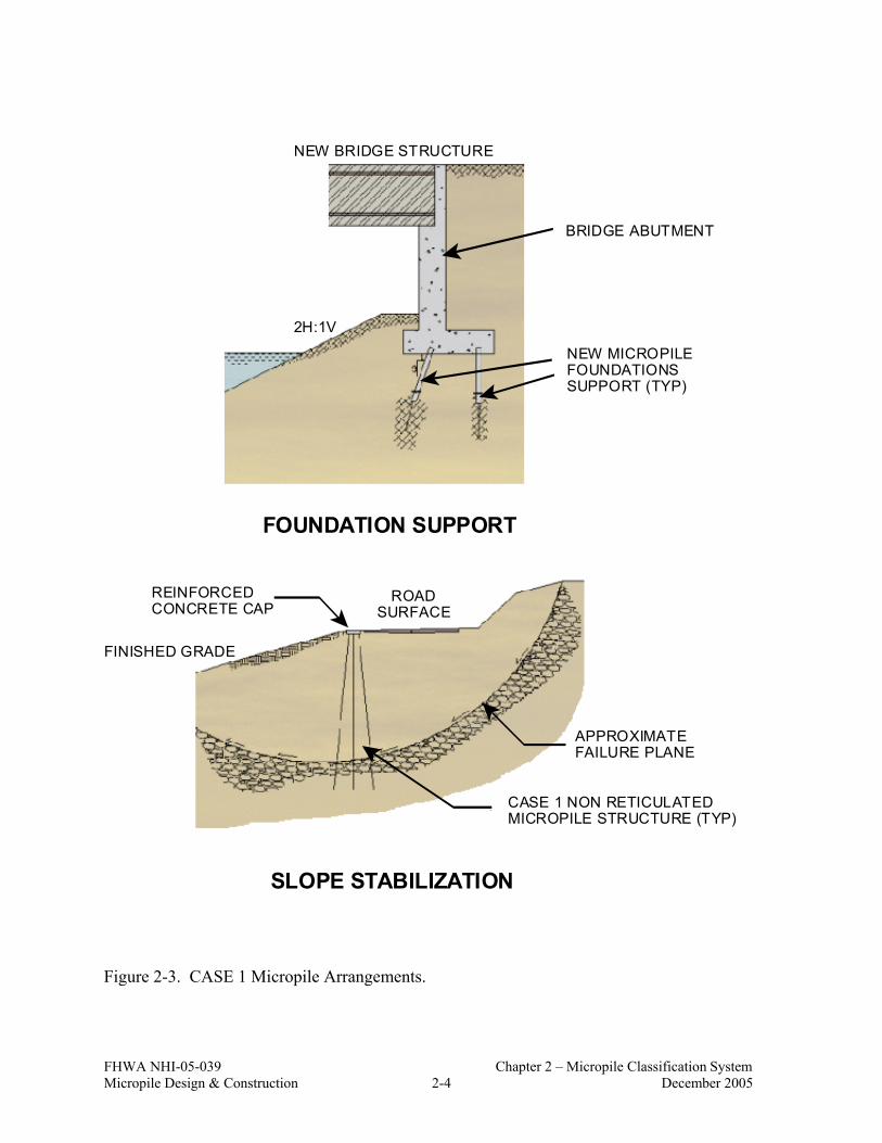
CASE 1 micropiles can be used as an alternative to more conventional types of piles since they are used to transfer structural loads to a deeper, more competent or stable stratum. Such directly loaded piles, whether for axial (compression or tension) or lateral loading conditions, are referred to as CASE 1 elements. The load is primarily resisted structurally by the steel reinforcement and geotechnically by side resistance developed over a “bond zone” of the individual micropiles. At least 90 percent of all international applications to date, and virtually all of the projects in North America have involved CASE 1 micropiles. Such micropiles are designed to act individually, although, they may be installed in groups. Typical arrangements of CASE 1 micropiles are illustrated in Figure 2-3.

FHWA NHI-05-039 Chapter 2 – Micropile Classification System Micropile Design & Construction 2-2 December 2005
MICROPILESDRILLEDSHAFT MICROPILES
DRILLEDSHAFT
VERTICAL LATERAL
COMPRESSIBLESTRATUM
BEARINGSTRATUM
EXTENT OFSOIL-PILE
INTERACTION
MICROPILES
DRILLEDSHAFT
MOVING SOIL
STABLE SOIL
EXTENT OFSOIL-PILE
INTERACTION
TO SUSTAIN AXIAL LOADS TO SUSTAIN LATERAL LOADS
Figure 2-1. CASE 1 Micropiles.

FHWA NHI-05-039 Chapter 2 – Micropile Classification System Micropile Design & Construction 2-3 December 2005
TO SUPPORT VERTICAL LOADAND LATERAL LOADS (IF NEEDED)
COMPOSITEBLOCK
TO LOWER CENTER OFGRAVITY OF SOIL-STRUCTUREUNIT TO IMPROVE STABILITY
COMPOSITEBLOCK
CAP BEAM
PALI RADICE (ROOT PILE)RETICULATED STRUCTURE
BLOCK CENTEROF GRAVITY
STRUCTURE CENTEROF GRAVITY
RESULTANT CENTEROF GRAVITY
Figure 2-2. CASE 2 Micropiles – Reticulated Micropile Network.
The remaining micropile applications involve networks of reticulated micropiles as components of a reinforced soil mass which is used to provide stabilization and support. These micropiles are referred to as CASE 2 elements. Structural loads are applied to the entire reinforced soil mass, as compared to individual micropiles (as for CASE 1 micropiles). CASE 2 micropiles are lightly reinforced because they are not individually loaded. A conceptual application of a network of reticulated micropiles is illustrated in Figure 2-4.
FHWA NHI-05-039 Chapter 2 – Micropile Classification System Micropile Design & Construction 2-4 December 2005
FOUNDATION SUPPORT
SLOPE STABILIZATION
NEW BRIDGE STRUCTURE
BRIDGE ABUTMENT
NEW MICROPILEFOUNDATIONSSUPPORT (TYP)
REINFORCEDCONCRETE CAP
ROADSURFACE
FINISHED GRADE
CASE 1 NON RETICULATEDMICROPILE STRUCTURE (TYP)
APPROXIMATEFAILURE PLANE
2H:1V
Figure 2-3. CASE 1 Micropile Arrangements.
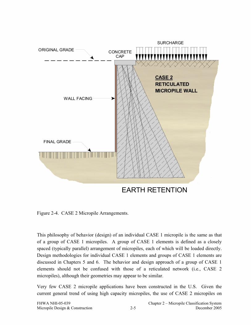
FHWA NHI-05-039 Chapter 2 – Micropile Classification System Micropile Design & Construction 2-5 December 2005
CONCRETECAP
SURCHARGE
ORIGINAL GRADE
FINAL GRADE
WALL FACING
CASE 2RETICULATEDMICROPILE WALL
EARTH RETENTION
Figure 2-4. CASE 2 Micropile Arrangements.
This philosophy of behavior (design) of an individual CASE 1 micropile is the same as that of a group of CASE 1 micropiles. A group of CASE 1 elements is defined as a closely spaced (typically parallel) arrangement of micropiles, each of which will be loaded directly. Design methodologies for individual CASE 1 elements and groups of CASE 1 elements are discussed in Chapters 5 and 6. The behavior and design approach of a group of CASE 1 elements should not be confused with those of a reticulated network (i.e., CASE 2 micropiles), although their geometries may appear to be similar.
Very few CASE 2 micropile applications have been constructed in the U.S. Given the current general trend of using high capacity micropiles, the use of CASE 2 micropiles on

FHWA NHI-05-039 Chapter 2 – Micropile Classification System Micropile Design & Construction 2-6 December 2005
future U.S. projects appears to be quite limited. Also, the use of CASE 2 micropiles, especially for public sector projects, will likely be disallowed until such time that an appropriate database of performance data becomes available for these micropiles to allow for a technically sound and safe design procedure to be developed.
2.3 CONSTRUCTION TYPE CLASSIFICATION
The method of grouting is typically the most sensitive construction process influencing grout/ground bond capacity. Grout/ground bond capacity varies directly with the grouting method. The second part of the micropile classification consists of a letter designation (A through D) based primarily on the method of placement and pressure under which grouting is performed during construction. The use of drill casing and reinforcement define sub-classifications. The classification is shown schematically in Figure 2-5 and is described subsequently.
• Type A: For Type A micropiles, grout is placed under gravity head only. Sand-cement mortars or neat cement grouts can be used. The micropile excavation may be underreamed to increase tensile capacity, although this technique is not common or used with any other micropile type.
• Type B: Type B indicates that neat cement grout is placed into the hole under pressure as the temporary drill casing is withdrawn. Injection pressures typically range from 0.5 to 1 MPa (72 to 145 psi) to avoid hydrofracturing the surrounding ground or causing excessive grout takes, and to maintain a seal around the casing during its withdrawal, where possible.
• Type C: Type C indicates a two-step process of grouting including: (1) neat cement grout is placed under gravity head as with Type A; and (2) prior to hardening of the primary grout (after approximately 15 to 25 minutes), similar grout is injected one time via a sleeved grout pipe without the use of a packer (at the bond zone interface) at a pressure of at least 1 MPa (145 psi). This pile type appears to be used only in France, and is referred to as IGU (Injection Globale et Unitaire).
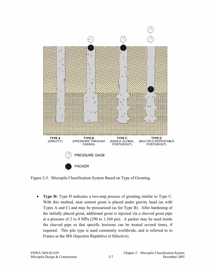
FHWA NHI-05-039 Chapter 2 – Micropile Classification System Micropile Design & Construction 2-7 December 2005
TYPE A(GRAVITY)
TYPE B(PRESSURE THROUGH
CASING)
TYPE C(SINGLE GLOBAL
POSTGROUT)
TYPE D(MULTIPLE REPEATABLE
POSTGROUT)
PRESSURE GAGE
PACKER
Figure 2-5. Micropile Classification System Based on Type of Grouting.
• Type D: Type D indicates a two-step process of grouting similar to Type C. With this method, neat cement grout is placed under gravity head (as with Types A and C) and may be pressurized (as for Type B). After hardening of the initially placed grout, additional grout is injected via a sleeved grout pipe at a pressure of 2 to 8 MPa (290 to 1,160 psi). A packer may be used inside the sleeved pipe so that specific horizons can be treated several times, if required. This pile type is used commonly worldwide, and is referred to in France as the IRS (Injection Répétitive et Sélective).

FHWA NHI-05-039 Chapter 2 – Micropile Classification System Micropile Design & Construction 2-8 December 2005
Table 2-1 provides additional information on Type A, B, C, and D micropiles. Sub-classifications (e.g., A1, A2, and A3) are included in Table 2-1 to indicate the type of drill casing and reinforcement used for each method of grouting. These sub-classifications also represent the type of reinforcement required by design (e.g. reinforcing bar, casing, none). Therefore, the combined micropile classification system is based on design application (i.e., Case 1 or Case 2), micropile type (i.e., Type A, B, C, or D) and grouting method (i.e., 1, 2, or 3). It is emphasized that Table 2-1 is intended to present a classification system based on the type of micropile construction. It is not intended to be used in contract specifications.
2.4 REFERENCES
FHWA (1997), “Drilled and Grouted Micropiles, State-of-Practice Review”, Bruce, D. A. and Juran, I., Reports No. FHWA-RD-96-016, 017, 018, and 019.
Pearlman, S. L., and Wolosick, J. R. (1992), “Pin Piles for Bridge Foundations,” Proceedings, 9th Annual International Bridge Conference, Pittsburgh, Pennsylvania, June 15-17.

FHWA NHI-05-039 Chapter 2 – Micropile Classification System Micropile Design & Construction 2-9 December 2005
Table 2-1. Details of Micropile Classification Based on Type of Grouting (after Pearlman and Wolosick, 1992).
Micropile Type and Grouting Method
Sub-type
Drill Casing Reinforcement Grout
A1 Temporary or unlined (open hole or auger)
None, single bar, cage, tube or structural section
A2 Permanent, full length
Drill casing itself Type A
Gravity grout only
A3 Permanent, upper shaft only
Drill casing in upper shaft, bar(s) or tube in lower shaft (may extend full length)
Sand/cement mortar or neat cement grout tremied to base of hole (or casing), no excess pressure applied
B1 Temporary or unlined (open hole or auger)
Monobar(s) or tube (cages rare due to lower structural capacity)
B2 Permanent, partial length
Drill casing itself
Type B
Pressure - grouted through the casing or
auger during withdrawal
B3 Permanent, upper shaft only
Drill casing in upper shaft, bar(s) or tube in lower shaft (may extend full length)
Neat cement grout is first tremied into drill casing/auger. Excess pressure (up to 1 MPa (145 psi) typically) is applied to additional grout injected during withdrawal of casing/auger
C1 Temporary or unlined (open hole or auger)
Single bars or tube (cages rare due to lower structural capacity)
C2 Not conducted –
Type C
Primary grout placed under gravity head, then one phase of
secondary “global” pressure grouting C3
Not conducted –
Neat cement grout is first tremied into hole (or casing/auger). Between 15 to 25 minutes later, similar grout injected through tube (or reinforcing pipe) from head, once pressure is greater than 1 MPa (145 psi)
D1 Temporary or unlined (open hole or auger)
Single bars or tube (cages rare due to lower structural capacity)
D2
Possible only if regrout tube placed full-length outside casing
Drill casing itself
Type D
Primary grout placed under gravity head (Type A) or under pressure (Type B). Then one or more
phases of secondary “global” pressure
grouting D3 Permanent, upper shaft only
Drill casing in upper shaft, bar(s) or tube in lower shaft (may extend full length)
Neat cement grout is first tremied (Type A) and/or pressurized (Type B) into hole or casing/auger. Several hours later, similar grout injected through sleeved pipe (or sleeved reinforcement) via packers, as many times as necessary to achieve bond

FHWA NHI-05-039 Chapter 2 – Micropile Classification System Micropile Design & Construction 2-10 December 2005

FHWA NHI-05-039 Chapter 3 – Micropile Transportation Applications Micropile Design & Construction 3-1 December 2005
CHAPTER 3 MICROPILE APPLICATIONS IN TRANSPORTATION
PROJECTS
3.1 INTRODUCTION
Micropiles are currently used in two general application areas: (1) structural support; and (2) in-situ reinforcement (Figure 3-1). Structural support includes new foundations, underpinning of existing foundations, seismic retrofitting applications and foundation support for earth retaining structures. In-situ reinforcement is used for slope stabilization and earth retention; ground strengthening; settlement reduction; and structural stability. Table 3-1 summarizes the typical design behavior and micropile construction type for each application.
Selection factors influencing the choice of micropiles for a project application are described herein. Example micropile applications for structural support and in-situ reinforcement for transportation projects and other civil engineering projects are described.
3.2 FEASIBILITY OF MICROPILES
3.2.1 Overview
Micropiles have specific advantages compared to more conventional support systems. In general, micropiles may be feasible under the following project-specific constraints:
• project has restricted access or is located in a remote area; • required support system needs to be in close pile proximity to existing structures; • ground and drilling conditions are difficult (e.g., karstic areas, uncontrolled fills,
boulders); • pile driving would result in soil liquefaction; • vibration or noise needs to be minimized; • hazardous or contaminated spoil material will be generated during construction; and • adaptation of support system to existing structure is required.
Limitations and cost information for micropiles are also presented in this section.

FHWA NHI-05-039 Chapter 3 – Micropile Transportation Applications Micropile Design & Construction 3-2 December 2005
Figure 3-1. Classification of Micropile Applications.
Review of Applications
Slope Stabilization
and Earth Retention
Ground
Strengthening
SettlementReduction
StructuralStability
Structural Support
In-situ Reinforcement
Earth Retaining Structure
Foundations
Foundationsfor
New Structures
Seismic Retrofitting
Underpinningof
Existing Foundations
Scour Protection
Repair/ Replacement
of Existing Foundations
Upgrading of
FoundationCapacity
Arresting/Prevention
of Movement

FHWA NHI-05-039 Chapter 3 – Micropile Transportation Applications Micropile Design & Construction 3-3 December 2005
Table 3-1. Relationship Between Micropile Application, Design Behavior and Construction Type (modified after FHWA, 1997).
STRUCTURAL
SUPPORT IN-SITU EARTH REINFORCEMENT
Application
Underpinning of Existing Foundations,
New Foundations, and Seismic Retrofitting
Slope Stabilization and Earth Retention
Ground Strengthening
Settlement Reduction
Structural Stability
Design Behavior CASE 1 CASE 1 and
CASE 2 CASE 2 with
minor CASE 1 CASE 2 CASE 2
Construction Type
Type A (bond zones in rock or stiff clays)
Type B, C, and D in soil
Type A and Type B in soil
Types A and B in soil
Type A in soil
Type A in soil
Frequency of Use
Probably 95 percent of total world applications 0 to 5 percent
3.2.2 Physical Considerations
The drilling and grouting equipment used for micropile installation is relatively small and can be mobilized in restrictive areas that would prohibit the entry of conventional pile installation equipment. Figure 3-2 shows micropiles being installed in low headroom conditions, illustrating the maneuverability of the equipment.
Micropiles can be installed in close proximity to existing walls or foundations, provided that there is space above for the drill-head and safe work zone or the micropiles are battered to provide this space. Micropile installation is not as affected by overhead power lines or other obstructions as are conventional pile installation systems. The equipment can be mobilized up steep slopes and in remote locations. Also, drilling and grouting procedures associated with micropile installations do not cause damage to adjacent existing structures or affect adjacent ground conditions when proper drilling and grouting procedures are utilized.

FHWA NHI-05-039 Chapter 3 – Micropile Transportation Applications Micropile Design & Construction 3-4 December 2005
Figure 3-2. Low Headroom Micropile Installation.
3.2.3 Subsurface Conditions
Micropiles can be installed in areas of particularly difficult, variable, or unpredictable geologic conditions such as ground with cobbles and boulders, fills with buried utilities and miscellaneous debris, and irregular lenses of competent and weak materials. Soft clays, running sands, and high groundwater not conducive to conventional drilled shaft systems cause minimal impacts to micropile installations. Micropiles are commonly used in karstic limestone formations.
3.2.4 Environmental Conditions
Micropiles can be installed in hazardous and contaminated soils. Because of their small diameter, drilling results in less spoil than would be produced by conventional drilled piles. Also, the flush effluent can be controlled easily at the ground surface through containerization or the use of lined surface pits. These factors greatly reduce the potential for surface contamination and handling costs.
Grout mixes can be designed to withstand chemically aggressive groundwater and soils. Special admixtures can be included in the grout mix design to reduce and avoid deterioration from acidic and corrosive environments. For example, a micropile “screen” was constructed from the installation of overlapping (secant) micropiles adjacent to an existing concrete
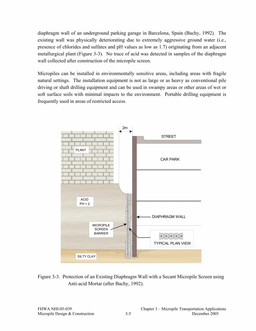
FHWA NHI-05-039 Chapter 3 – Micropile Transportation Applications Micropile Design & Construction 3-5 December 2005
diaphragm wall of an underground parking garage in Barcelona, Spain (Bachy, 1992). The existing wall was physically deteriorating due to extremely aggressive ground water (i.e., presence of chlorides and sulfates and pH values as low as 1.7) originating from an adjacent metallurgical plant (Figure 3-3). No trace of acid was detected in samples of the diaphragm wall collected after construction of the micropile screen.
Micropiles can be installed in environmentally sensitive areas, including areas with fragile natural settings. The installation equipment is not as large or as heavy as conventional pile driving or shaft drilling equipment and can be used in swampy areas or other areas of wet or soft surface soils with minimal impacts to the environment. Portable drilling equipment is frequently used in areas of restricted access.
STREET
CAR PARK
DIAPHRAGM WALL
PLANT
ACIDPH < 2
MICROPILESCREENBARRIER
SILTY CLAY
TYPICAL PLAN VIEW
2m
Figure 3-3. Protection of an Existing Diaphragm Wall with a Secant Micropile Screen using Anti-acid Mortar (after Bachy, 1992).

FHWA NHI-05-039 Chapter 3 – Micropile Transportation Applications Micropile Design & Construction 3-6 December 2005
Micropile installations cause less noise and vibration than conventional piling techniques, especially driven piles. The vibration from pile driving is imparted to the soil and can be transferred through the soil to adjacent structures. The use of micropiles in old urban environments and industrial/manufacturing areas can prevent this potential damage to adjacent sensitive structures and equipment.
Micropiles can be installed in areas where there is a contaminated aquifer overlying a bearing strata. Unlike driven piles that may produce a vertical conduit for contaminate migration, micropiles can be installed in a manner preventing contamination of lower aquifers.
3.2.5 Existing Structure Adaptation
Micropiles can be added to an existing pile cap, thereby eliminating the need for an increased footing size. With this approach, the additional compression, tension and moment resistance associated with increased structural loads can be resisted effectively. Oftentimes adjacent utilities and/or structures restrict the possibility of enlarging the existing pile caps, thus eliminating more traditional piling systems. With this approach, design analyses need to consider the relative stiffness of the micropiles and the existing piles to estimate individual loads.
3.2.6 Micropile Limitations
Vertical micropiles may be limited in lateral capacity and cost effectiveness. The ability of micropiles to be installed on an incline, however, significantly enhances their lateral capacity. Because of their high slenderness ratio (length/diameter), micropiles may not be acceptable for conventional seismic retrofitting applications in areas where liquefaction may occur due to concerns of buckling resulting from loss of lateral support.
The use of micropiles for slope stabilization continues to increase. However, it is recommended that performance data be collected on such projects as experience and detailed design procedures continue to evolve.
3.2.7 Economics of Micropiles
The lineal cost of micropiles usually exceeds that of conventional piling systems, especially driven piles. A detailed discussion on micropile costs is provided in Chapter 10.
Cost effectiveness of micropiles depends on many factors. It is important to assess the cost of using micropiles based on the physical, environmental, and subsurface factors previously described. For example, for an open site with soft, clean, uniform soils and unrestricted

FHWA NHI-05-039 Chapter 3 – Micropile Transportation Applications Micropile Design & Construction 3-7 December 2005
access, micropiles will likely not be a competitive solution. However, for the delicate underpinning of an existing bridge pier in a heavily trafficked old industrial or residential area, micropiles can provide the most cost-effective solution.
Care should be taken to clearly define the true final cost of a solution based on micropiles. Cost analysis should be based on all related costs for the entire project and not just the unit cost of the piling system. As with other pile systems, it would be beneficial to consider micropile costs in terms of $/kN of axial capacity when evaluating deep foundation alternatives. Micropile costs are associated with:
• right-of-way acquisition; • right-of-way agreements; • utility realignment; • excavation, shoring and backfill requirements; • footing construction; • hazardous material handling; • dewatering; • erosion control; • access restrictions; • ground improvement; and • owner and neighbor disruption.
3.3 STRUCTURAL SUPPORT
3.3.1 Overview
Micropile applications for structural support include foundations for new structures, underpinning of existing structures, scour protection, and seismic retrofitting of existing structures. Many of these applications have been used for transportation projects. In this section, case histories involving these applications are provided.
3.3.2 New Foundations
Micropiles are applicable in new bridge construction in areas that require deep foundation alternatives or in difficult ground (cobbles/boulders obstructions) where installation of conventional piles or drilled shafts is very difficult and/or expensive.
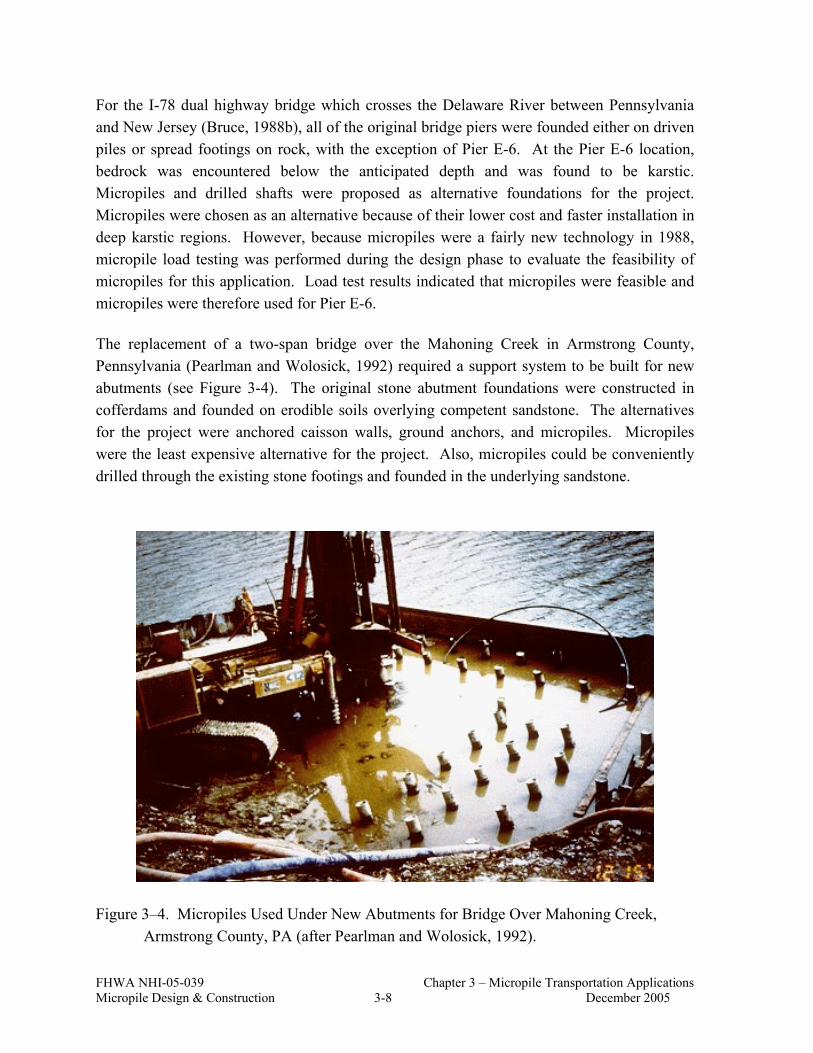
FHWA NHI-05-039 Chapter 3 – Micropile Transportation Applications Micropile Design & Construction 3-8 December 2005
For the I-78 dual highway bridge which crosses the Delaware River between Pennsylvania and New Jersey (Bruce, 1988b), all of the original bridge piers were founded either on driven piles or spread footings on rock, with the exception of Pier E-6. At the Pier E-6 location, bedrock was encountered below the anticipated depth and was found to be karstic. Micropiles and drilled shafts were proposed as alternative foundations for the project. Micropiles were chosen as an alternative because of their lower cost and faster installation in deep karstic regions. However, because micropiles were a fairly new technology in 1988, micropile load testing was performed during the design phase to evaluate the feasibility of micropiles for this application. Load test results indicated that micropiles were feasible and micropiles were therefore used for Pier E-6.
The replacement of a two-span bridge over the Mahoning Creek in Armstrong County, Pennsylvania (Pearlman and Wolosick, 1992) required a support system to be built for new abutments (see Figure 3-4). The original stone abutment foundations were constructed in cofferdams and founded on erodible soils overlying competent sandstone. The alternatives for the project were anchored caisson walls, ground anchors, and micropiles. Micropiles were the least expensive alternative for the project. Also, micropiles could be conveniently drilled through the existing stone footings and founded in the underlying sandstone.
Figure 3–4. Micropiles Used Under New Abutments for Bridge Over Mahoning Creek, Armstrong County, PA (after Pearlman and Wolosick, 1992).
FHWA NHI-05-039 Chapter 3 – Micropile Transportation Applications Micropile Design & Construction 3-9 December 2005
The use of micropiles allows new bridge foundations to be constructed in areas of existing overhead restrictions, while maintaining traffic flow. A major improvement project was undertaken to replace the deck of the Brooklyn-Queens Expressway in the Borough of Brooklyn, New York (Bruce and Gemme, 1992). As a part of this project, a new center lane and several new entry/exit ramps were required. Micropiles were the only alternative for the new viaduct and the ramp construction because of low headroom restrictions and stringent vibration restrictions during construction. Due to low headroom conditions, micropile casing were left full length in the ground. Also, traffic flow was maintained during construction. Although the site comprised variable fluvioglacial deposits, this did not affect the rapid installation of the micropiles.
Other micropile applications used for structural support include buildings, earth retaining structures, and soundwalls. Figure 3-5 shows typical arrangements of micropiles for support of common transportation-related structures.
3.3.3 Underpinning of Existing Foundations
Micropiles were originally developed for underpinning existing structures. The underpinning of existing structures may be performed for many purposes, including:
• arresting and preventing structural movement; • for upgrading load-bearing capacity of existing structures; • repair and replacement of deteriorating or inadequate foundations; • to provide scour protection for erosion-sensitive foundations; • raising previously settled foundations; and • providing a means to transfer loads to deeper strata.
Micropiles can be installed through and bonded within existing structures providing direct connection with competent underlying strata without the need for new pile caps, while at the same time reinforcing the structure internally.
Construction can be executed without reducing the existing foundation capacity. The West Emerson Street Viaduct project in Seattle, Washington (Figure 3-6) required additional foundation support to be built at the existing bents. The additional foundation support had to be designed for both tension and compression loads. The conditions at the site included tight access and low headroom. Low headroom caissons and micropiles were the alternatives for the project. Micropiles were chosen to be added on five existing bents because of their considerable low cost compared to low headroom caissons.
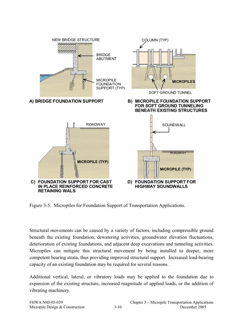
FHWA NHI-05-039 Chapter 3 – Micropile Transportation Applications Micropile Design & Construction 3-10 December 2005
NEW BRIDGE STRUCTURE
BRIDGEABUTMENT
MICROPILEFOUNDATIONSUPPORT (TYP)
COLUMN (TYP)
MICROPILES
SOFT GROUND TUNNEL
ROADWAY
MICROPILE (TYP)
ROADWAY
MICROPILE (TYP)
SOUNDWALL
A) BRIDGE FOUNDATION SUPPORT B) MICROPILE FOUNDATION SUPPORTFOR SOFT GROUND TUNNELINGBENEATH EXISTING STRUCTURES
C) FOUNDATION SUPPORT FOR CASTIN PLACE REINFORCED CONCRETERETAINING WALS
D) FOUNDATION SUPPORT FORHIGHWAY SOUNDWALLS
Figure 3-5. Micropiles for Foundation Support of Transportation Applications.
Structural movements can be caused by a variety of factors, including compressible ground beneath the existing foundation, dewatering activities, groundwater elevation fluctuations, deterioration of existing foundations, and adjacent deep excavations and tunneling activities. Micropiles can mitigate this structural movement by being installed to deeper, more competent bearing strata, thus providing improved structural support. Increased load-bearing capacity of an existing foundation may be required for several reasons.
Additional vertical, lateral, or vibratory loads may be applied to the foundation due to expansion of the existing structure, increased magnitude of applied loads, or the addition of vibrating machinery.

FHWA NHI-05-039 Chapter 3 – Micropile Transportation Applications Micropile Design & Construction 3-11 December 2005
Figure 3-6. Underpinning of West Emerson Street Viaduct, Seattle, Washington.
The 75-year-old Pocomoke River Bridge in Maryland was rehabilitated when the capacity of the original wooden piles of the pier foundations was compromised by exposure to river scour (Bruce et al., 1990). Any alternative foundations system would need to be constructed in the middle of the river. The improved foundation system for the bridge was required to be preloaded before connecting to the existing structure to prevent additional settlement of the sensitive structure. Micropiles and caissons were considered for this project, and micropiles were selected for the project and installed through the existing foundation. The underpinning arrangement for the Pocomoke Bridge using micropiles is shown in Figure 3-7.
Another underpinning example is the expansion of the Exton Square Mall in Chester County, Pennsylvania (Cadden et al., 2001). The mall site is underlain by dolomitic limestone, which is defined by Pennsylvania Department of Environmental Resources as a hazardous rock due to its susceptibility to solutioning and sinkhole development. Deep foundations had to be used in order to support column loads up to 4,450 kN (1,000 kips). The alternatives evaluated for the project included drilled shafts, driven piles, and micropiles. Project constraints included performing the work while most of the stores remained open and performing all the interior work at night when the mall was closed. Micropiles were chosen as an alternative because they were judged to be best suited to the tight access, low headroom, logistical restrictions, irregular rock mass quality, and high individual pile working loads. Driven piles were not feasible because they would likely become damaged during installation.

FHWA NHI-05-039 Chapter 3 – Micropile Transportation Applications Micropile Design & Construction 3-12 December 2005
MICROPILE (TYP)
WEST ABUTMENT(DRIVEN TIMBER PILES)
EAST ABUTMENT(DRIVEN TIMBER PILES)
BASCULEPIER 3
BASCULEPIER 4
30.4 m 32 m 30.4 m
Figure 3-7. Underpining Arrangement for Pocomoke River Bridge, Maryland (after Bruce et al., 1990).
3.3.4 Seismic Retrofit
Micropiles are being used increasingly for seismic retrofitting of existing highway structures, especially in California. Micropiles exhibit near equal tension and compression capacities, therefore optimizing the additional foundation support elements used (Bruce and Chu, 1995). Micropiles may be economically feasible for bridge foundation retrofits having one or more of the following constraints:
• restrictions on footing enlargements; • vibration and noise restrictions; • low headroom clearances; • difficult access; • high axial load demands in both tension and compression; • difficult drilling/driving conditions; and • hazardous soil sites.
Micropiles were used as part of a seismic retrofit project for California Department of Transportation’s earthquake retrofit project at I-110 in Los Angeles (Pearlman et al., 1993).

FHWA NHI-05-039 Chapter 3 – Micropile Transportation Applications Micropile Design & Construction 3-13 December 2005
Micropiles were used at the north connector over-crossing (Figure 3-8). Initially drilled shafts were chosen for the project; however, difficult drilling conditions, including buried concrete obstructions and water-bearing flowing sand layers, low overhead conditions, and limited right-of-way access prohibited the use of drilled shafts. Micropiles were chosen for the project due to their lower cost and ability to be installed under difficult access conditions. Micropiles for this project were designed for tension and compression and were connected to the existing structure.
Figure 3-8. Seismic Retrofit of I-110, North Connector, Los Angeles, California.
Micropiles were used to upgrade existing foundations for a highway bridge along Route 57 near Cairo, Illinois. The seismicity for this area of southern Illinois is controlled by the New Madrid Seismic Source Zone. Micropiles were designed to withstand lateral and vertical forces from the design earthquake. The site soils consist of approximately 7.5 m (25 ft) of silty clay overlying sands. The existing pier and abutment foundations include short, vertical and batter timber piles deriving resistance from the sandy soils. The installation of a total of 240 micropiles occurred under low headroom conditions (under the bridge deck) and required excavation around the existing pier foundations. Ten micropiles were installed just

FHWA NHI-05-039 Chapter 3 – Micropile Transportation Applications Micropile Design & Construction 3-14 December 2005
outside the perimeter of each foundation. Reinforcing steel was doweled into the existing footing and a new pile cap was poured.
Micropiles have also been used for earthquake retrofit of major bridges in the San Francisco Bay area and New York City.
3.4 IN-SITU REINFORCEMENT
Micropiles are used in two different ways to stabilize slopes. Lizzi (1982) suggests that micropiles be used as reticulated network systems (CASE 2), which creates a stable, reinforced-soil, “gravity-retaining wall”. In CASE 2 systems the reinforced soil gravity mass supplies the essential resisting force, and the micropiles, encompassed by the soil, supply additional resistance to the tensile and shear forces acting on the “wall”. Alternately, Pearlman and Wolosick (1992) and Palmerton (1984) suggest that groups of individual inclined micropiles could be used to stabilize the slope because they serve to connect the moving zone (above the failure surface) to the stable zone (below the failure surface). These micropiles provide reinforcement to resist the shearing forces that develop along the failure surface. Typical configurations of inclined micropile groups for slope stabilization and earth retention are shown in Figure 3-9.
For rocky, stiff, or dense materials, the shear resistance of the micropiles across the failure surface, i.e., individual capacity; is critical (CASE 1). For loose materials, the micropiles and soil are mutually reinforcing and creating a gravity wall, so the individual micropile capacities are not as significant (CASE 2).
Micropiles were used to stabilize a portion of State Road 4023 in Armstrong County, Pennsylvania (Bruce, 1988a). A 75-m (250-ft) long section of this road and railroad tracks located upslope were experiencing damage from slope movements towards an adjacent river. Rock anchors and tangent drilled shafts extending into rock were the proposed techniques for in-situ reinforcement. However, alternative bidding was allowed in the project. During bidding, inclined micropile groups were proposed as an alternative to proposed techniques and were accepted due to significant cost savings. The resultant savings was approximately $1 million compared to the lowest bid for the anchored drilled shaft wall design. The wall included four rows of micropiles extending across the failure plane and into competent rock (Figure 3-10).
Micropiles were used to provide temporary excavation support for a project involving improvements to State Highway 82 near Aspen, Colorado (Macklin et al., 2004). In this

FHWA NHI-05-039 Chapter 3 – Micropile Transportation Applications Micropile Design & Construction 3-15 December 2005
mountainous region, construction is hampered by difficult site access and slope instability risks. This site consists of loose to very dense silty to gravelly sand with cobbles and boulders, which were deposited as debris flow, sheet wash, and colluvium over dense alluvial sandy gravel with cobbles. Originally, temporary shoring using combinations of soil nails and tiebacks was considered for the project. However, in an effort to improve the construction schedule and phasing, micropiles were selected as an alternative temporary shoring system. The micropile shoring implemented on this project was essentially a hybrid between a soldier beam and lagging system and a soil nail stabilization system (Figure 3-11). Phasing of the project required constructing a number of bridges in a specific sequence. The micropile shoring system allowed the contractor to transition access road grades where convenient, depending upon the excavation and access requirements for any phase of the work.
STEEL REINFORCING BAR(28 mm TO 63 mm TYP)
GROUT
125mm - 230mm 125mm - 230mm
(c) PILE SECTIONS
STEEL PIPE (100 mmTO 175 mm O.D. TYP)
(a) ROADWAY SLOPE (b) SLOPE ABOVE HIGHWAY
Figure 3-9. Typical Configurations for Inclined Micropile Walls.

FHWA NHI-05-039 Chapter 3 – Micropile Transportation Applications Micropile Design & Construction 3-16 December 2005
0.3m (MIN)
1.37m (MIN)
2H:1V
VARIES 150mm TO 1200mm
0.91m
CONCRETE CAP153mm MUD SLAB
EXISTING GRADE
15m±
TOP OFROCK
ROW 1(26E)
ROW 2(16E)
ROW 3(9E)
ROW 4(VERT)
140mm DIA
115mm DIA
Figure 3-10. State Road 4023 Micropile Slope Stabilization, Armstrong County, Pennsylvania (after Bruce, 1988a).

FHWA NHI-05-039 Chapter 3 – Micropile Transportation Applications Micropile Design & Construction 3-17 December 2005
The Portland Westside Light-Rail Project in Portland, Oregon is an example of the use of micropiles to provide permanent earth retention (Ueblacker, 1996). Wall 600 extends from the east portal of the Westside Light-Rail cut and cover tunnel approximately 183 m (600 ft) to just beneath the Vista Avenue Bridge. Cut heights along the retaining wall ranged from 4 to 9.5 m (13 to 30 ft). The original design included a counterfort concrete retaining wall supported on a driven pile foundation. The micropile wall was accepted as a contractor-proposed value engineering alternate, largely because it was an alternate solution that could be constructed within the available right-of-way. Micropiles were installed vertically and inclined (Figure 3-12). Shotcrete was used for a temporary facing with the permanent facing comprising an architecturally treated cast-in-place concrete.
An early example of slope stabilization using reticulated micropiles was for Forest Highway 7 in Mendocino National Forest, California (Palmerton, 1984). This project was one of the two reticulated micropiles built in U.S. at the time. The site could have been stabilized using either cantilever or anchored walls; however, there was an interest in this relatively new technology and micropiles were therefore selected as part of a demonstration project. The two-lane road of Forest Highway 7 was constructed across a landslide where slide movement had occurred as a result of excessive rainfall (Figure 3-13). A 94-m (305-ft) long section of the road was stabilized using reticulated micropiles (Figure 3-14).
Feasibility evaluation for micropiles is discussed further in Chapter 5 for structural support applications and Chapter 6 for slope stabilization applications.
Figure 3-11. Cross Section Showing Steep Canyon Slope and Temporary Micropile Shoring (after Macklin et al., 2004).

FHWA NHI-05-039 Chapter 3 – Micropile Transportation Applications Micropile Design & Construction 3-18 December 2005
GEOCOMPOSITE DRAIN
TRACK BALLAST
ORIGINAL COUNTERFORTWALL ENVELOPE
MICROPILES
GRADE BEAM
75mm DIA WATER MAINS
EXISTING GRADE
STRUCTURALFILL
100mm MIN TEMP. SHOTCRETE FACING
305mm CIP PERMANENTWALL FACING
Figure 3-12. Wall 600 Permanent Earth Retention, Portland, Oregon (after Ueblacker, 1996).
Figure 3-13. Photo of Slope Stabilization at FH-7 Project in Mendocino National Forest, California.

FHWA NHI-05-039 Chapter 3 – Micropile Transportation Applications Micropile Design & Construction 3-19 December 2005
PILE BATTER V:HA,AN,B,BN
C
D, DN
E, EN
G, GN
F, FN
VERT.
10 : 3.4
10 : 2.6
10 : 1.3
10 : 1
10 : 1.4
ASSUMEDFAILUREPLANE
PILE CAP
GAGE DEPTH 1.22m
5.50m
3.05m
7.93m
11.89m
10.37m
13.11m
127mm – DIAMETERREINFORCED PILE
BA D E F G C GNFN EN DN BNAN
DOWNHILLUPSTATION
Figure 3-14. Schematic of Slope Stabilization at FH-7 Project in Mendocino National Forest, California.
FHWA NHI-05-039 Chapter 3 – Micropile Transportation Applications Micropile Design & Construction 3-20 December 2005
3.5 REFERENCES
Bachy (1992), “Interception of Pollution by Impervious Barrier;” Sancho de Avila Car Park, Barcelona, Spain, Promotional literature, Paris, France.
Bruce, D. A. (1988a), “Developments in Geotechnical Construction Processes for Urban Engineering”, Civil Engineering Practice, Vol. 3, No. 1, Spring, pp. 49-97.
Bruce, D. A., (1988b), “Aspects of Minipiling Practice in the United States,” Ground Engineering, Vol. 21, No. 8, pp. 20-33.
Bruce, D. A., Pearlman, S. L., and Clark, J. H. (1990), “Foundation Rehabilitation of the Pocomoke River Bridge, Maryland, Using High Capacity Preloaded Pinpiles,” Proceedings, 7th Annual International Bridge Conference, Pittsburgh, Pennsylvania, June 18-20, Paper IBC-90-42, 9 pages.
Bruce, D. A. and Gemme, R., (1992) “Current Practice in Structural Underpinning Using Pinpiles,” Proceedings, New York Met Section, ASCE Seminar, New York, April 21-22, 46 pages.
Bruce, D. A., and Chu, E. K. (1995), “Micropiles for Seismic Retrofit, Proceedings,” National Seismic Conference on Bridges and Highways, Sponsored by FHWA and Caltrans, San Diego, California, December 10-13, 17 pages.
Cadden, A. W., Bruce, D. A., and Ciampitti, L. M. (2001), “Micropiles in Karst: A Case History of Difficulties and Success”, Foundations and Ground Improvement, Proceedings of a Specialty Conference, ASCE, June 9-13, Geotechnical Special Publication, No. 113, pp. 204-215.
FHWA (1997), Drilled and Grouted Micropiles, State-of-Practice Review. Federal Highway Administration Publication, Report No. FHWA-RD-96-016/019, July 1997, Four Volumes.
Lizzi, F. (1982), “The Pali Radice (Root Piles),” Symposium on Soil and Rock Improvement Techniques including Geotextiles, Reinforced Earth and Modern Piling Methods, Bangkok, December, Paper D1.

FHWA NHI-05-039 Chapter 3 – Micropile Transportation Applications Micropile Design & Construction 3-21 December 2005
Macklin, P. R., Berger, D., Zietlow, W., Herring, W., and Cullen, J. (2004), “Case History: Micropile Use for Temporary Excavation Support”, Geotechnical Special Publication “Drilled Shafts, Micropiling, Deep Mixing, Remedial Methods, and Specialty Foundation Systems”, ASCE Publication, No.: 124, pp: 653-661.
Palmerton, J.B. (1984), “Stabilization of Moving Land Masses By Cast-In-Place Piles,” USACOE Waterways Experiment Station, Final Report GL-84-4.
Pearlman, S. L., and Wolosick, J. R. (1992), “Pin Piles for Bridge Foundations,” Proceedings, 9th Annual International Bridge Conference, Pittsburgh, Pennsylvania, June 15-17.
Pearlman, S.L., Campbell, B.D., and Withiam, J.L. (1992), “Slope Stabilization Using InSitu Earth Reinforcements” ASCE Specialty Conference on Stability and Performance of Slopes and Embankments – II, Berkeley, California.
Pearlman, S.L., Wolosick, J.R., and Gronek, P.B. (1993), “Pin Piles for Seismic Rehabilitation of Bridges,” Proceedings 9th International Bridge Conference, Pittsburg, Pennsylvania.
Ueblacker, G. (1996), “Portland Westside Lightrail Corridor Project Micropile Retaining Wall,” Foundation Drilling, November, pp. 8-12.

FHWA NHI-05-039 Chapter 3 – Micropile Transportation Applications Micropile Design & Construction 3-22 December 2005

FHWA NHI-05-039 Chapter 4 – Construction Techniques & Materials Micropile Design & Construction 4-1 December 2005
CHAPTER 4 CONSTRUCTION TECHNIQUES AND MATERIALS
4.1 INTRODUCTION
The purpose of this chapter is to familiarize design engineers and construction personnel with the different techniques and materials utilized in the construction of micropiles. Specifically, information is provided on: (1) types of drill rigs used for micropile drilling; (2) various techniques used for overburden and open hole drilling; (3) grout types with methods of mixing and placing; and (4) types of micropile reinforcement. The construction of a micropile involves a succession of processes, the most significant of which are drilling, placing the reinforcement, and grouting. There are a large number of drilling systems available for both overburden and rock and many are used for micropile construction.
The typical construction sequence for simple Type A and B micropiles (Figure 4-1) includes drilling the pile shaft to the required tip elevation, placing the steel reinforcement, placing the initial grout by tremie, and placing additional grout under pressure (for Type B). In general, the drilling and grouting equipment and techniques used for the micropile construction are similar to those used for the installation of soil nails, ground anchors, and grout holes.
4.2 DRILLING
4.2.1 Overview
Most drilling methods selected by the specialty contractor for a micropile project are likely to be acceptable on a particular project, provided they can form a stable hole of the required dimensions and within the stated tolerances, and without detriment to their surroundings. It is important not to exclude a particular drilling method because it does not suit a predetermined concept of how the project should be executed. It is equally important that the drilling contractor be knowledgeable of the project ground conditions, and the effects of the drilling method chosen. Drilling within a congested urban site in close proximity of older buildings or deteriorating foundations has very different constraints than drilling for new foundations on an open field site.

FHWA NHI-05-039 Chapter 4 – Construction Techniques & Materials Micropile Design & Construction 4-2 December 2005
BEGIN DRILLING&/OR INSTALLATION
OF TEMPORARYCASING
COMPLETEDRILLING TO
DEPTH
REMOVE INNERDRILL BIT &
ROD (IF USED)
PLACEREINFORCEMENT &GROUT (BY TREMIE)
REMOVETEMPORARY
CASING, INJECTFURTHER GROUT
UNDERPRESSURE ASAPPLICABLE
COMPLETE PILE(CASING MAY BELEFT IN PLACETHROUGH THE
COMPRESSIBLESTRATUM)
ADDITIONAL GROUT
COMPRESSIBLESTRATUM
BEARINGSTRATUM
Figure 4-1. Typical Micropile Construction Sequence Using Casing.
The act of drilling and forming the pile excavation may disturb the surrounding ground for a certain time and over a certain distance. The drilling method selected by the contractor should avoid causing an unacceptable level of disturbance to the site and its facilities, while providing for installation of a micropile that supports the required capacities in the most cost-effective manner. Vigorous water flushing can increase drilling rates and increase the removal of the fine components of mixed soils, enlarging the effective diameter in the bond zone and aiding in grout penetration and micropile capacity. Conversely, the use of higher flush flow rates and pressures should be approached with caution, with consideration to the risks of creating voids and surface settlement, and the risks of hydrofracturing the ground which could result in ground heave.
Drilling, installation of the reinforcement, and grouting of a particular micropile should be completed in a series of continuous processes and executed as expeditiously as possible. Longer durations between completion of drilling and placing of the reinforcement and grout can be detrimental to the integrity of the surrounding soil. Some materials, such as overconsolidated clays and clay shales, can deteriorate, relax, or soften as a result of

FHWA NHI-05-039 Chapter 4 – Construction Techniques & Materials Micropile Design & Construction 4-3 December 2005
exposure, resulting in a loss of interfacial bond capacity. In these cases, installation of a micropile bond zone should be completed within one day to avoid a pile hole remaining open overnight.
Other site-specific conditions may affect selection of the drilling method and flush type. The use of water flush may require the supply, handling, and disposal of large quantities of water. In areas where the water supply may be scarce, a series of ponds or tanks for settlement and recirculation of the water may be necessary. Requirements for cleanliness or lack of space for water handling and disposal may dictate the use of air flush or augers for hole drilling. The presence of hazardous materials in the ground and the need for careful control and disposal of the soil cuttings may also necessitate the use of augers for micropile installation.
4.2.2 Drill Rigs
Drill rigs typically used for micropile installation are hydraulic rotary (electric or diesel) power units. They can be track mounted allowing for maneuverability on difficult and sloped terrain. The size of the track-mounted drills can vary greatly, as seen in Figure 4-2 and 4-3, with the larger drill allowing use of long sections of drill rods and casing in areas without overhead restrictions and the smaller drill allowing work in lower overhead and harder-to-reach locations. The drill mast can be mounted on a frame allowing work in limited-access and low-overhead areas, such as building basements.
Figure 4-2. Large Track-Mounted Rotary Hydraulic Drill Rig.

FHWA NHI-05-039 Chapter 4 – Construction Techniques & Materials Micropile Design & Construction 4-4 December 2005
(a)
(b)
Figure 4-3. Low Headroom Track-Mounted Rotary Hydraulic Drill Rig (a) not Mounted and (b) Mounted for Drilling.

FHWA NHI-05-039 Chapter 4 – Construction Techniques & Materials Micropile Design & Construction 4-5 December 2005
A frame-mounted drill such as the one shown in Figure 4-4 can be connected with long hoses to a separate hydraulic rotary power unit. This allows placement of the power unit outside the area of work, thus reducing space requirements, noise in the work area, and problems with exhaust removal. The drill frame can be moved and supported with a fork lift or moved by hand with winches and supported by bolting to a concrete floor, and/or bridge footing or bracing from a ceiling or bridge soffit.
The rotary head that turns the drill string (casing, augers, or rods) can be extremely powerful on even the smallest of rigs, allowing successful installation in the most difficult ground conditions. Shortening of the drill mast and the use of short jointed sections of drill string and micropile reinforcement allows pile installation with less than 3 m (10 ft) of overhead clearance. For a vertical micropile, the micropile centerline can be located within approximately 375 mm (15 in.) of the face of an adjacent wall. This distance may need to increase for micropiles larger than approximately 175 mm (7 in.) in diameter.
Figure 4-4. Small Frame-Mounted Rotary Hydraulic Drill Rig.

FHWA NHI-05-039 Chapter 4 – Construction Techniques & Materials Micropile Design & Construction 4-6 December 2005
4.2.3 Drilling Techniques
The drilling method is selected with the objective of causing minimal disturbance or upheaval to the ground and structure while being the most efficient, economic, and reliable means of penetration. Micropiles must often be drilled through an overlying weak material to reach a more competent bearing stratum. Therefore, construction typically requires the use of overburden drilling techniques to penetrate and support weak and unconsolidated soils and fills. In addition, unless the bearing stratum is a self-supporting material, such as rock or a cohesive soil, the drill hole may need temporary support for its full length, e.g. through the use of temporary casing (Figure 4-5) or suitable drilling fluid. If self-supporting material is present for the full depth of the micropile, the drillhole can possibly be formed by open hole techniques, i.e., without the need for temporary hole support by drill casing or hollow stem auger.
Alternative drilling methods are required to penetrate through an existing structure (Figure 4-6). Concrete coring techniques may be used to provide an oversized hole in existing slabs and footings to allow the subsequent drill casing to pass through. In some cases, conventional rock drilling methods involving rotary percussive techniques can be used to penetrate existing lightly-reinforced footings and structures. Rotary percussive (Figure 4-7) or rotary duplex (Figure 4-8) techniques may be used to first penetrate an initial obstruction layer, such as concrete rubble, with more conventional single-tube advancement drilling used for completion of the micropile shaft in the soil layers below.

FHWA NHI-05-039 Chapter 4 – Construction Techniques & Materials Micropile Design & Construction 4-7 December 2005
Figure 4-5. Casing with Heavy Duty Casing Crown.
(a) (b)
Figure 4-6. Drill Rigs Equipped (a) with Tricone Roller Bit and (b) for Double Head Drilling.

FHWA NHI-05-039 Chapter 4 – Construction Techniques & Materials Micropile Design & Construction 4-8 December 2005
(a) (b)
Figure 4-7. Rotary Percussive Drilling (a) Drive Head and (b) Drive Bit and Shoe.
(a) (b)
Figure 4-8. Rotary Duplex Drilling (a) Drill Rods and (b) Various Casing Shoes.

FHWA NHI-05-039 Chapter 4 – Construction Techniques & Materials Micropile Design & Construction 4-9 December 2005
Water is the most common medium for cleansing and flushing the hole during drilling, followed by air, drill slurries, and foam. Caution should be exercised while using air flush to avoid injection of the air into the surrounding ground, causing fracturing and heaving. The use of bentonite slurries to stabilize and flush holes will impair grout-to-ground bond capacity by creating a skin of clay at the interface; however, this is not an uncommon choice in Italian and French practice with Type D piles. Polymer drilling muds have been used successfully in micropile construction in all types of ground. This slurry type reduces concern for impairment of the bond capacity, and allows for easier cleanup and disposal versus bentonite slurry.
4.2.4 Overburden Drilling Techniques
There is a large number of proprietary overburden drilling systems sold by drilling equipment suppliers worldwide. In addition, specialty contractors often develop their own variations in response to local conditions and demands. The result is large selection of systems and methods. However, seven generic methods have been identified which are common for piles with diameters less than 300 mm (12 in) to depths less than 60 m (200 ft). The following is a brief discussion of these seven methods. These seven methods are also summarized in Table 4-1, and simply represented in Figure 4-9.
Figure 4-9. Overburden Drilling Methods (modified after Bruce, 1989).

FHWA NHI-05-039 Chapter 4 – Construction Techniques & Materials Micropile Design & Construction 4-10 December 2005
Table 4-1. Overburden Drilling Methods (after Bruce, 1989).
Drilling Method Principle Common Diameters and Depths Notes
Single-tube advancement
a) Drive drilling Casing with “lost point” percussed without flush
50-100 mm to 30 m (2-4 in. to 100 ft)
Obstructions or very dense soil problematic. 1
b) External flush Casing, with shoe, rotated with strong water flush.
100-250 mm to 60 m (4-10 in. to 200 ft)
Needs high torque head and powerful flush pump.
2 Rotary duplex
Simultaneous rotation and advancement of casing plus internal rod, carrying flush. Rod may have down-the-hole hammer.
100-220 mm to 70 m (4-8.75 in. to 230 ft)
Used only in very sensitive soil/site conditions. Needs positive flush return. Needs high torques. (Internal flushing only)
3 Rotary percussive concentric duplex
As 2, except casing and rods percussed as well as rotated.
89-175 mm to 40 m (3.5-7 in. to 130 ft)
Useful in obstructed/rocky conditions. Needs powerful top rotary percussive hammer.
4 Rotary percussive eccentric duplex
As 2, except eccentric bit on rod cuts oversized hole to ease casing advance.
89-200 mm to 60 m (3.5-8 in. to 200 ft)
Expensive and difficult system used for difficult overburden. Rod can be percussive at top, or may have down-the-hole hammer above bit.
5 “Double head” duplex
As 2 or 3, except casing and rods may rotate in opposite directions.
100-150 mm to 60 m (4-6 in. to 200 ft)
Powerful, new system for fast, straight drilling in very difficult ground. Need significant hydraulic power. Casing can be percussed by top hammer. Rod may be percussed by top hammer or may have down-the-hole hammer above bit.
6 Hollow-stem auger
Auger rotated to depth to permit subsequent introduction of grout and/or reinforcement through stem.
100-400 mm to 30 m (4-16 in. to 100 ft)
Obstructions problematic; care must be exercised in cohesionless soils. Prevents application of higher grout pressures.
7 Sonic Casing is excited by a variable frequency, variable amplitude, sonic head
100 to 300 mm to 100 m
(4-12 in. to 330 ft)
No or minimal flush needed. Full length sample of soil recovered for each hole.
Note: Drive drilling, being purely a percussive method, is not described in the text as it has no application in micropile construction.

FHWA NHI-05-039 Chapter 4 – Construction Techniques & Materials Micropile Design & Construction 4-11 December 2005
• Single-Tube Advancement-External Flush (Wash Boring): The toe of the drill casing is fitted with an open crown or bit and the casing is advanced into the ground by rotation of the drill head. Water flush is pumped continuously through the casing, which washes debris out and away from the crown. The water-borne debris typically escapes to the surface around the outside of the casing, but may be lost into especially loose and permeable strata. Care must be exercised below sensitive structures in order that uncontrolled washing does not damage the structure by causing cavitation.
Air flush is not normally used with this system due to the danger of accidentally over pressurizing the ground in an uncontrolled manner which can cause ground disturbance. Conversely, experience has shown that polymer drill flush additives can be very advantageous in certain ground conditions, in place of water alone (Bruce, 1992). These do not appear to detrimentally affect grout-to-soil bond development as may be the case with bentonite slurries.
• Rotary Duplex: The drill rod with a suitable drill bit is placed inside the drill casing. It is attached to the same rotary head as the casing, allowing simultaneous rotation and advancement of the combined drill and casing string. The flushing fluid, usually water or polymer flush, is pumped through the head down through the central drill rod to exit from the flushing ports of the drill bit. The flush-borne debris from the drilling then rises to the surface along the annulus between the drill rod and the casing. At the surface, the flush exits through ports in the drill head. Air flush must be used with caution because blockages within the annulus can allow high air pressures to develop at the drill bit and cause ground disturbance.
• Rotary Percussive Duplex (Concentric): Rotary percussive duplex systems are a development of rotary duplex methods, whereby the drill rods and casings are simultaneously percussed, rotated, and advanced. The percussion is provided by a top-drive rotary percussive drill head. This method requires a drill head of substantial rotary and percussive energy.
• Rotary Percussive Duplex (Eccentric or Lost Crown): Originally sold as the Overburden Drilling Eccentric (ODEX) System, this method involves the use of rotary percussive drilling combined with an eccentric underreaming bit. The eccentric bit undercuts the drill casing, which is then pushed into the oversized drill hole with much less rotational energy or thrust than is required with the concentric method. The drill casing does not require an expensive cutting shoe and suffers less wear and abrasion. The larger diameter options, of more than 127 mm (5 in.) in diameter, often involve the use of a down-the-hole hammer acting on a drive shoe at

FHWA NHI-05-039 Chapter 4 – Construction Techniques & Materials Micropile Design & Construction 4-12 December 2005
the toe of the casing so that the casing is effectively pulled into the borehole as opposed to being pushed by a top hammer.
• Double Head Duplex: With the double head duplex method, the rods and casings are rotated by separate drill heads mounted one above the other on the same carriage. These heads provide high torque (and so enhanced soil- and obstruction-cutting potential), but at the penalty of low rotational speed. However, the heads are geared such that the lower one (rotating the outer casing), and the upper one (rotating the inner drill string) turn in opposite directions. The resulting aggressive cutting and shearing action at the bit permits high penetration rates, while the counter-rotation also minimizes blockage of the casing/rod annulus by debris carried in the exiting drill flush. In addition, the inner rods may operate by either purely rotary techniques or rotary percussion using top-drive or down-the-hole hammers. The counter-rotation feature promotes exceptional hole straightness and penetrability, even in the most difficult ground conditions.
• Hollow-Stem Auger: Hollow-stem augers are continuous flight auger systems with a central hollow core similar to those commonly used in auger-cast piling or for subsurface investigation. These are installed by purely rotary heads. When drilling down, the hollow core is closed off by a cap on the drill bit. When the hole has been drilled to depth, the cap is knocked off or blown off by grout pressure, permitting the pile to be formed as the auger is withdrawn. Such augers may be used for drilling cohesive materials, very soft rocks, and are commonly used in sands. If used in sands with minimal cohesion or adhesion, there is a danger of loosening or cavitating the soil, especially in inclined holes. Post grouting is essential (Type D).
Various forms of cutting shoes or drill bits can be attached to the lead auger, but heavy obstructions, such as old foundations and cobble and boulder soil conditions, are difficult to penetrate economically with this system. In addition, great care must be exercised when using augers as uncontrolled penetration rates or excessive “hole cleaning” may lead to excessive spoil removal, thereby risking soil loosening or cavitation in certain circumstances.
• Sonic: Sonic drilling is a dual cased drilling system that employs high frequency mechanical vibration to take continuous core samples of overburden and most bedrock formations, and to advance casing into the ground. Other names for sonic drilling include rotosonic, rotasonic, sonicore, vibratory or resonant sonic drilling. The entire drill string is vibrated at a frequency of between 50 and 150 hertz and evenly distributes the energy and wear at the drill bit face. The rig uses a specially

FHWA NHI-05-039 Chapter 4 – Construction Techniques & Materials Micropile Design & Construction 4-13 December 2005
designed hydraulically powered drill head or oscillator that is attached directly to the core barrel, drill pipe or outer casing. The vibrations are sent down through the drill steel to the face of the drill bit creating displacement, fracturing or shearing action depending on the material being drilled.
4.2.5 Open Hole Drilling Techniques
When a micropile can be formed in stable and free-standing conditions, the advancement of casing may be suspended and the hole continued to final depth by open-hole drilling techniques. There is a balance in cost between the time lost in changing to a less-expensive open-hole system and continuing with a more expensive overburden drilling system for the full hole depth. Open-hole drilling techniques may be classified as follows:
• Rotary Percussive Drilling: Particularly for rocks of high compressive strength, rotary percussive techniques using either top-drive or down-the-hole hammers are utilized. For the small hole diameters used for micropiles, down-the-hole techniques are the most economical and common. Air, air/water mist, or foam is used as the flush.
Top-drive systems can also use air, water, or other flushing systems, but have limited diameter and depth capacities, are relatively noisy, and may cause damage to the structure or foundation through excessive vibration.
• Solid Core Continuous Flight Auger: In stiff to hard clays without boulders and in some weak rocks, drilling may be conducted with a continuous flight auger. Such drilling techniques are rapid, quiet, and do not require the introduction of a flushing medium to remove the spoil. There may be the risk of lateral decompression or wall remolding/interface smear, either of which may adversely affect grout-to-ground bond. Such augers may be used in conditions where the careful collection and disposal of drill spoils are particularly important.
• Underreaming: Various devices have been developed to enlarge or underream open holes in cohesive soils or soft sediments, especially when the micropiles are to act in tension. These tools can be mechanically or hydraulically activated and will cut or abrade single or multiple underreams or “bells.” However, this is a time-consuming process, and it is rarely possible or convenient to verify its effectiveness. In addition, the cleaning of the underreams is often difficult; water is the best cleaning medium, but may cause softening of the ground. For all these reasons, it is rare to find underreaming used in typical micropile practice.

FHWA NHI-05-039 Chapter 4 – Construction Techniques & Materials Micropile Design & Construction 4-14 December 2005
4.3 GROUTING
4.3.1 General
As described in Chapter 2, the grouting operations have a major impact on micropile capacity. Details of each type of grouting operation vary somewhat throughout the world, depending on the origins of the practice and the quality of the local resources. However, as general observations, it may be noted that:
• Grouts are designed to provide high strength and stability (i.e., bleed), but must also be pumpable. As shown in Figure 4-10, this implies typical water/cement (w/c) ratios in the range of 0.40 to 0.50 by weight for micropile grout. In Figure 4-10, bleed capacity is defined as amount of free water that develops at final set. For example, for a w/c ratio of 1.0, 100 liters of grout would develop 20 liters of free water.
• Grouts are produced with potable water, to reduce the danger of reinforcement corrosion.
1 N/mm2 = 145 psi
1 dyne/cm2 = 1.45 × 10⁻⁵ psi
Figure 4-10. Effect of Water Content on Grout Compressive Strength and Flow Properties (after Littlejohn and Bruce, 1977).

FHWA NHI-05-039 Chapter 4 – Construction Techniques & Materials Micropile Design & Construction 4-15 December 2005
• Type I/II cement conforming to ASTM C150/AASHTO M85 is most commonly used, supplied either in bagged or bulk form depending on site condition, job size, local availability, and cost.
• Neat cement-water grout mixes are most commonly used, although sand is a common additive in certain countries (e.g., Italy, Britain). Bentonite (which reduces grout strength) is used in primary mixes only with extreme caution, while additives are allowed only for cases where improved pumpability is required as for pumping over long distances and/or in hot conditions (e.g., high-range water reducers).
• Design compressive strengths of 28 to 35 MPa (4,000 to 5,000 psi) can be attained with properly produced neat cement grouts.
• If admixtures and/or additives are used, it is essential that they are chemically compatible. This is best achieved by using only one chemical supplier, and not by “mixing and matching”.
The placed grout is required to serve a number of purposes, as described below.
• It transfers the imposed loads between the reinforcement and the surrounding ground.
• It may form part of the load-bearing cross section of the micropile.
• It serves to protect the steel reinforcement from corrosion.
• Its effects may extend beyond the confines of the drill hole by permeation, densification, and/or fissuring.
The grout, therefore, needs to have adequate properties of fluidity, strength, stability, and durability. The need for grout fluidity can mistakenly lead to an increase in water content which has a negative impact on the other three properties. Of all the factors that influence grout fluidity and set properties, the water/cement ratio is the most important. Again, Figure 4-10 illustrates why this ratio is limited to a range of 0.40 to 0.50, although even then, additives may be necessary to ensure adequate pumpability for ratios less than 0.40.
It is essential to the integrity of the micropile that upon completion of the grouting operation, there is no significant loss of grout from any part of the micropile that will be relied upon for load bearing or corrosion protection. This condition can be achieved by grouting to refusal during micropile formation, i.e. continue grouting until no more grout take occurs. Problems with grout loss may necessitate the use of a filler such as sand for plugging the permeable layer, or may require pre-grouting the hole and redrilling and regrouting after set of the initial grout. Loss of grout is judged simply by observing the level of grout which remains in the hole after the grout has stiffened. For general guidance, a grout take over twice the “neat”

FHWA NHI-05-039 Chapter 4 – Construction Techniques & Materials Micropile Design & Construction 4-16 December 2005
hole volume is indicative of voided or very permeable conditions warranting special attention.
For a Type B micropile, it may not always be possible to attain the desired pressures during grouting; the soil seal around the casing may not always be adequate to contain the pressurized grout. This may occur after partial pressure grouting of the bond length. If this occurs, the grout should be pumped until the level reaches the top of pile, at which time grouting is discontinued. Maintaining grout pressures at a reasonable level (0.70 MPa (100 psi) or less) will help prevent this from occurring. If the bond lengths of the test micropiles (that verified the geotechnical capacity) are grouted full length with the desired pressure, questions may be raised as to the adequacy of micropiles that are grouted under partial pressure. One benefit of conducting micropile tests to typically 150 to 200 percent of the design load or greater is that it helps to determine if the micropiles have excess geotechnical capacity. Production proof tests (described in Chapter 7) may be conducted on the suspect micropiles.
Because the grout is such a vital component of the micropile, close attention must be paid to the control and quality of the product. A grout quality control plan, which at a minimum should include cube or cylinder compression testing and grout density (water /cement ratio) testing, is discussed in Chapter 8.
Comprehensive guides to cement grout mix design, performance, and equipment are provided in Littlejohn (1982), Gourlay and Carson (1982), and Houlsby (1990). Similar issues relating solely to the similar demands of prestressed ground anchors are summarized by Littlejohn and Bruce (1977).
4.3.2 Grout Equipment
In general, any plant suitable for the mixing and pumping of fluid cementitious grouts may be used for the grouting of micropiles. The best quality grouts, in terms of both fluid and set properties, are produced by high-speed, high-shear colloidal mixers (see Figure 4-11) as opposed to low-speed, low-energy mixers, such as those that depend on paddles (Figure 4-12). High speed mixers are faster and produce a homogeneous grout mix (see Section 4.3.3). Mixing equipment can be driven by air, diesel, or electricity, and is available in a wide range of capacities and sizes from many manufacturers.
For grout placement, lower pressure injection (up to 2 MPa (290 psi)) and up to 200 liters/min (52 gal/min)) is usually completed using constant pressure, rotary-screw type pumps (e.g., Moyno pumps), while higher pressure grouting, such as for Type C or D

FHWA NHI-05-039 Chapter 4 – Construction Techniques & Materials Micropile Design & Construction 4-17 December 2005
micropiles, usually requires a fluctuating pressure piston or ram pump, which can deliver up to 8 MPa (1,160 psi) at up to 50 liters/min (13 gal/min).
VORTEX DRUM HANY MIXER
THE ORIGINAL CHEMGROUTCOLLOIDAL MIXER
SKETCH OF LATER CHEMGROUT MIXER
CEMIX MIXERSLeft: MODEL 175 Right: MODEL 200
DOUBLE-ROTOR CONCRETE MIXER
DISCHARGEVALVE
ROTOR ROTOR
ROTOR ROTOR
ROTOR
VORTEX DRUM DISCHARGEVALVE
CONCRETE MIXER HANDY MIXER
ORIGINAL CHEMGROUTCOLLOIDAL MIXER
MODIFIED CHEMGROUT MIXER
CEMIX MIXERLeft MODEL 176 Right MODEL 200
DOUBLE-ROTOR COLCRETE MIXER
Figure 4-11. Various Types of High Speed, High Shear “Colloidal” Mixers.

FHWA NHI-05-039 Chapter 4 – Construction Techniques & Materials Micropile Design & Construction 4-18 December 2005
END VIEW ELEVATION ELEVATION
MOTOR
A A
PADDLES
SECTION AAHORIZONTAL PADDLE MIXER
CHEMGROUT PADDLE MIXER
PROPELLERFIXED IN
DRUM
PORTABLEPROPELLER
VERTICAL PADDLE MIXER
MOVABLEPROPELLER
END VIEW ELEVATION ELEVATION
MOTOR
A A
PADDLES
SECTION AAHORIZONTAL PADDLE MIXER
CHEMGROUT PADDLE MIXER
PROPELLERFIXED IN
DRUM
PORTABLEPROPELLER
VERTICAL PADDLE MIXER
MOVABLEPROPELLER
Figure 4-12. Various Types of Paddle Mixers.

FHWA NHI-05-039 Chapter 4 – Construction Techniques & Materials Micropile Design & Construction 4-19 December 2005
4.3.3 Grout Mixing
During mixing, a measured volume of water is usually added to the mixer first, followed by cement and then aggregate or filler (if applicable). It is generally recommended that grout be mixed for a minimum of two minutes and that thereafter the grout is kept in continuous slow agitation in a holding tank prior to being pumped to the micropile. Only in cases where exceptionally large grout takes are anticipated should ready-mix grout be considered. The grout should be injected within a certain maximum time after mixing. This “safe workability” time should be determined on the basis of on-site tests, but is typically not in excess of one hour. There is no question that high speed high shear mixers produce higher quality, more consistent grout more quickly than do paddle mixers. Bearing in mind the relatively large cement particle surface area to be “wetted” (measured in “football fields” per single 43 kg bag), and that this must be accomplished with less than 20 liters of water, the intimate blending generated by the high speed mixer is essential for efficient hydration.
Water is typically batched into the mixer by means of a calibrated tank or flow meter. Cement is typically batched by weight, either in bags or by bulk from a silo. Sand or fillers are also batched by weight from premeasured bags or more commonly, by using a gage box that has previously been checked and weighed. For bulk material, some method must be provided for controlling the quantities of components (volume or weight measurement) added to the mix. Admixtures are usually provided ready-proportioned to a single bag of cement, or the dosage can be adjusted by the mixer operator.
4.3.4 Grout Placement Techniques
4.3.4.1 Gravity Fill Techniques (Type A Micropiles)
For Type A micropiles, the hole is drilled to depth and it is then filled with grout and the reinforcement is placed. Grout should always be introduced into the drill hole through a tremie pipe exiting at the bottom of the hole. Grout is pumped into the bottom of the hole until grout of similar quality to that being injected is freely flowing from the mouth of the borehole. No excess pressure is applied. This type and phase of grouting is referred to as the primary treatment.
The grout usually comprises a neat cement mix with w/c ratio between 0.45 and 0.50 by weight. Additionally, sanded mixes of up to 1:1 or 2:1 sand:cement ratio have been used in European practice, but they are becoming less common due to a growing trend towards the use of higher grouting pressures involving neat cement grouts. Gravity fill techniques tend now to be used only when the pile is founded in rock, or when low-capacity piles are being installed in stiff or hard cohesive soils, and pressure grouting is unnecessary (Bruce and

FHWA NHI-05-039 Chapter 4 – Construction Techniques & Materials Micropile Design & Construction 4-20 December 2005
Gemme, 1992). For sanded mixes, the w/c ratio is often extended to 0.60, assuming the resultant mix remains stable (i.e., bleed less than 5 percent and sand does not segregate) (Barley and Woodward, 1992). In the U.S., sanded mixes are only used for pregrouting, e.g., in karst terrains, for economic reasons.
4.3.4.2 Pressure Grouting Through the Casing (Type B Micropiles)
For Type B micropiles, additional grout is injected under pressure after the primary grout has been tremied, and as the temporary casing is being withdrawn. The aim is to enhance the grout-to-ground bond characteristics. This operation can be limited to the load transfer length within the design-bearing stratum, or may be extended to the full length of the pile where appropriate.
Pressure grouting is usually conducted by attaching a pressure cap to the top of the drill casing (this is often the drilling head itself) and injecting additional grout into the casing under controlled pressure. In the past, pressurization of the grout was achieved by applying compressed air through the grout line, since contemporary drill head details and grout pump technology could not accommodate the relatively viscous, sand-cement mortars. This method has now been rendered obsolete by the developments in pump capabilities, combined with the trend to use stable, neat cement grouts without sand.
Grout pressures are measured as close to the point of injection as possible, to account for line losses between pump and hole. Commonly, a pressure gauge is mounted on the drill rig and monitored by the driller as a guide for rate of casing withdrawal during the pressurization phase. Alternatively, if a grouting cap is used and the casing is being extracted by means other than the drill rig (e.g., by hydraulic jacks), it is common to find a pressure gauge mounted on the cap itself. Practitioners acknowledge that there will be line losses in the system, but typically record the pressure indicated on the pressure gauge without the correction, reasoning that such losses are compensated by the extra pressure exerted by the grout column due to its weight in the borehole. The recommended method is to install a pressure gauge on the drill rig or on the line just at the cap.
American practice is to inject additional grout at a typical average pressure between 0.5 to 1 MPa (72 to 145 psi), with the aim of reinstating in-situ lateral soil pressures that may have been reduced by the drilling process and achieving permeation into coarser grained granular soils or fractured rocks. The maximum applied injection pressures (typically 20 kPa per meter (18 psi per ft) of depth in loose soils and 40 kPa per meter (36 psi per ft) of depth in dense soils) are dictated by the following factors:
• need to avoid ground heave or uncontrolled loss of grout;

FHWA NHI-05-039 Chapter 4 – Construction Techniques & Materials Micropile Design & Construction 4-21 December 2005
• nature of the drilling system (permissible pressures are lower for augers due to leakage at joints and around the flights);
• ability of the ground to form a “seal” around the casing during its extraction and pressure grouting;
• need to avoid “seizing” the casing by flash setting of the grout due to excessive pressure, preventing proper completion of the pile;
• required grout-to-ground bond capacity; and • total micropile depth.
The injection of grout under pressure is aimed at improving grout-to-ground skin friction, thus enhancing the load-carrying capacity of the micropile. Extensive experience with ground anchors has confirmed the effect of pressure grouting on ultimate load-holding capacity.
When pressure grouting in granular soils, a certain amount of permeation and displacement (i.e., slight redensification or compaction occurs to “repair” the soil locally loosened during drilling) of loosened soils takes place. Additionally, a phenomenon known as pressure filtration occurs, wherein the applied grout pressure forces some of the integral mixing water out of the cement suspension and into the surrounding soil. This process leaves behind a grout of lower water content than was injected and is thus quicker setting and of higher strength. It also causes the formation of cake-like cement paste along the grout/soil interface that improves bond. In cohesive soils, some lateral displacement, compaction, or localized improvement of the soil can occur around the bond zone, although the improvement is generally less than for cohesionless soils.
Pressure grouting also appears to cause a recompaction or redensification of the soil around the borehole and increases the effective diameter of the pile in the bond zone. These mechanisms effectively enhance grout/soil contact, leading to higher skin friction values and improved load/displacement performance. Such pressure grouting may also mechanically improve the soil between piles.
4.3.4.3 Postgrouting (Type C and D Micropiles)
It may not be possible to exert sufficiently high grout pressures during the casing removal stage due to potential ground hydrofracture or leakage around the casing. In addition, some micropile construction methods may not use or need a temporary drill casing, and so pressure grouting of the Type B method is not feasible. These circumstances have led to the development of post-grouting techniques, whereby additional grout can be injected via special grout tubes some time after the placing of the primary grout (Figure 4-13). Such grouts are always neat cement-water mixes (for the ease of pumpability through the rubber

FHWA NHI-05-039 Chapter 4 – Construction Techniques & Materials Micropile Design & Construction 4-22 December 2005
valves) and may therefore have higher w/c ratios than the primary grout, being in the range of 0.50 to 0.75 by weight. It is reasoned that excess water from these mixes is expelled by pressure filtration during passage into the soil, and so the actual placed grout has a lower water content (and therefore higher strength).
As described in the following paragraphs, high postgrouting pressures are typically applied, locally, for quite restricted periods; it may only take a few minutes to inject a sleeve. However, higher grout-to-ground bond capacity may, in fact, be more efficiently achieved in Type B micropiles, where grouting pressures are lower but are exerted over a larger area and a much longer period.
Postgrouting techniques Type C and Type D micropiles are described below.
• Type C: Neat cement grout is placed in the hole as done for Type A micropiles. Between 15 and 25 minutes later, and before hardening of this primary grout, similar grout is injected once from the head of the hole without a packer, via a 38- to 50-mm (1.5- to 2-in.) diameter preplaced sleeved grout pipe through the reinforcement at a pressure of at least 1 MPa (145 psi) (Figure 4-14).
Type D: Neat cement grout is placed in the hole as done for Type A micropiles. When this primary grout has hardened, similar grout is injected via a preplaced sleeved grout pipe. Several phases of such injection are possible at selected horizons and it is typical to record pressures of 2 to 8 MPa (290 to 1,160 psi), especially at the beginning of each sleeve treatment when the surrounding primary grout must be ruptured for the first time. There is usually an interval of at least 24 hours before successive phases. Three or four phases of injection are not uncommon, contributing additional grout volumes of as much as 250 percent of the primary volume.

FHWA NHI-05-039 Chapter 4 – Construction Techniques & Materials Micropile Design & Construction 4-23 December 2005
REINFORCINGSTEEL
BOND ZONE(SOIL / GROUTINTERFACE)
CEMENT GROUT(FIRST PHASE)
CLOSED RUBBERSLEEVE
SLEEVED PIPE
DOUBLEPACKER (TYP)
POST GROUT(SECOND PHASE)
OPEN RUBBERSLEEVE
Figure 4-13. Principle of the Tube á Manchette Method of Postgrouting Injection.
The postgrout tube can be a separate 25- or 38-mm (1- or 1.5-in.) diameter sleeved plastic pipe (tube à manchette) placed together with the steel reinforcement (Figure 4-13), or it can be the reinforcement tube itself, suitably sleeved (Figure 4-14). In each of these cases, a double packer may be used to grout through the tubes from the bottom sleeve upwards.

FHWA NHI-05-039 Chapter 4 – Construction Techniques & Materials Micropile Design & Construction 4-24 December 2005
DRILL HOLEDIAMETER
STEEL TUBE
DOUBLE PACKER
NON RETURN VALVE(MANCHETTE)
ANNULUS GROUT(GROUT PRESSURE)
1st PHASE PRESSURE GROUT
2nd PHASE PRESSURE GROUT
Figure 4-14. Use of Reinforcement Tube as a Tube á Manchette Postgrouting System.
Alternatively, pressure grouting can be conducted from the surface via a circulating-loop arrangement. By this method, grout is pumped around the system and the pressure is increased steadily by closing the pressurization value on the outlet side. At the critical “break out” pressure, dictated by the lateral resistance provided by the adjacent grout, the

FHWA NHI-05-039 Chapter 4 – Construction Techniques & Materials Micropile Design & Construction 4-25 December 2005
grout begins to flow out of the tube through one or more sleeves and enters the ground at that horizon. When using the loop method, it is assumed that with each successive phase of injection that a different sleeve opens ultimately resulting in treatment over the entire sleeved length (a feature guaranteed by the tube à manchette method using double packers) (Figure 4-15).
Figure 4-15. Circulating Loop Arrangement for Pressure Grouting (DSI, 1992).

FHWA NHI-05-039 Chapter 4 – Construction Techniques & Materials Micropile Design & Construction 4-26 December 2005
Where micropile structural capacity depends on the compressive strength of the grout, the use of low-strength bentonite primary grouts to reduce “break out” pressures should be avoided.
4.3.5 Top-Off (Secondary) Grouting
Due to slow grout seepage, bleed, or shrinkage, it is common to find that the grout level drops slightly prior to stiffening and hardening. In ground anchorage practice, this is simply rectified by topping off the hole with the lowest water-content grout practical, at some later phase. However, in micropile practice where a permanent casing for reinforcement of the upper micropile length is not used, such a cold joint should be avoided since the grout column should be continuous for load holding and corrosion protection reasons. Topping off is therefore best conducted during the stiffening phase to ensure integrity. Where particularly high interfacial bond stresses must be resisted between the micropile and an existing structure, the use of a high-strength non-shrink grout may be considered.
4.4 REINFORCING STEEL
4.4.1 General
The amount of steel reinforcement placed in a micropile is determined by the loading it supports and the stiffness required to limit elastic displacements. Reinforcement may consist of a single reinforcing bar, a group of reinforcing bars, a steel pipe casing or rolled structural steel. In American practice, the use of a single reinforcing bar and/or a high-strength steel casing is commonly used.
4.4.2 Placement of Reinforcement
Reinforcement may be placed either prior to grouting, or placed into the grout-filled borehole before the temporary support (if used) is withdrawn. It must be clean of deleterious substances such as surface soil and mud that may contaminate the grout or coat the reinforcement, impairing bond development. Suitable centralizers should be firmly fixed to maintain the specified grout cover. Pile cages and reinforcement groups, if used, must be sufficiently robust to withstand the installation and grouting process and the rotation and withdrawal of the temporary casing.
4.4.3 Reinforcement Types
A description of the various types of reinforcement is provided in this section.

FHWA NHI-05-039 Chapter 4 – Construction Techniques & Materials Micropile Design & Construction 4-27 December 2005
• Concrete Reinforcing Steel Bars (rebar): Standard reinforcing steel (Table 4-2), conforming to ASTM A615/AASHTO M31and ASTM A706, with yield strengths of 420 and 520 MPa (60 and 75 ksi), is typically used. Bar sizes range in diameter from 25 mm to 63 mm (1 to 2.5 in.). A single bar is typically used, but bar groups have been used. For a bar group, the individual bars can be separated by the use of spacers or tied to the helical reinforcement, to provide area for grout to flow between the bars and ensure adequate bonding between the bars and grout (Figure 4-16). Alternatively, bars can be bundled as long as adequate development length for the bundle is provided.
Table 4-2. Dimensions, Yield, and Ultimate Strengths for Standard Reinforcing Bars.
Steel Grade Rebar Size, mm (in) Area, mm2 (in.2) Yield Strength, kN (kip) 19 (#6) 284 (0.44) 117 (26) 22 (#7) 387 (0.60) 160 (36) Grade 420(1)
25 (#8) 510 (0.79) 211 (47) 19 (#6) 284 (0.44) 147 (33) 22 (#7) 387 (0.60) 200 (45)
25 (#8) 510 (0.79) 264 (59) 29 (#9) 645 (1.0) 334 (75
32 (#10) 819 (1.27) 424 (95) 36 (#11) 1006 (1.56) 520 (117) 43 (#14) 1452 (2.25) 751 (169)
Grade 520(2)
57 (#18) 2581 (4.0) 1335 (3000)
Grade 550(3) 63 (2.5 in) 3168 (4.91) 1747 (393) Notes: (1)Grade 420 steel has yield stress of fy= 420 MPa (60 ksi) and tensile strength of fu = 620
MPa (92 ksi) (2)Grade 520 steel has yield stress of fy= 520 MPa (75 ksi) and tensile strength of fu = 690
MPa (102 ksi) (3)Grade 550 steel has yield stress of fy = 550 MPa (80 ksi) and tensile strength of fu = 700
MPa (104 ksi)

FHWA NHI-05-039 Chapter 4 – Construction Techniques & Materials Micropile Design & Construction 4-28 December 2005
245 mm OD x 12 mm WALLTHICKNESS STEEL CASING
75 mm REINFORCINGBAR (TYP)
BAR CENTRALIZER
NEAT CEMENT GROUT280 mm DIAMETERDRILLED HOLE
PILECL
120E
Figure 4-16. Multiple Bar Reinforcement with Bar Centralizer/Spacer.
For low overhead conditions where placement of full-length bars is not feasible, mechanical couplers can be used. Field adjustment of individual bar lengths can be difficult if the coupler type requires shop fabrication.
• Continuous-Thread Steel Bars: Steel reinforcing bars may be fabricated with a continuous full-length thread, such as the Dywidag Systems International (DSI) Threadbar or the Williams All-Thread Bar.
The DSI Threadbar system, which is also referred to as a GEWI Threadbar (Figure 4-17 and Table 4-3), is a common choice throughout the world for micropile reinforcement. The bar has a coarse pitch, continuous ribbed thread rolled on during production. It is available in diameters ranging from 19 mm to 63 mm (3/4 to 2-1/2 in.) in steel conforming to ASTM A615/AASHTO M 31, with yield strengths of 420,

FHWA NHI-05-039 Chapter 4 – Construction Techniques & Materials Micropile Design & Construction 4-29 December 2005
520, and 550 MPa (60, 75, and 80 ksi). The size range of 32 mm to 63 mm (1-1/4 to 2-1/2 in.) is most commonly used. Higher strength bars of steel conforming to ASTM A722/AASHTO M 275 with an ultimate strength of 1,035 MPa (150 ksi) are also available, in diameters of 26, 32, and 36 mm (1, 1-1/8, and 1-3/8 in.).
Figure 4-17. Details of DSI Threadbar (DSI, 1993).
Table 4-3. Dimensions and Yield Strength for DSI Threadbar.
Steel Grade
Bar Diameter mm (in)
Area mm2 (in2)
Yield Strength kN (kip)
Diameter over
Threads mm (in.)
Bar Weight kg/m (lbs/lf)
32 (#10) 819 (1.27) 424 (95) 36.3 (1.43) 6.41 (4.30) 36 (#11) 1006 (1.56) 520 (117) 40.9 (1.61) 7.91 (5.31) 43 (#14) 1452 (2.25) 751 (169) 47.2 (1.86) 11.39 (7.65)
520(1)
57 (#18) 2581 (4.0) 1335 (300) 63.5 (2.5) 20.24 (13.6) 550(2) 63 (2.5in) 3168 (4.91) 1747 (393) 69.1 (2.72) 24.86 (16.7)
Notes: (1)Grade 500 steel has yield stress of fy= 520 MPa (75 ksi) and tensile strength of fu = 690 MPa (100 ksi).
(2)Grade 550 steel has yield stress of fy= 552 MPa (80 ksi) and tensile strength of fu = 700 MPa (102 ksi).
The Williams All-Thread Bar is available in diameters ranging from 20 to 89 mm (0.8 to 3.5 in.) in steel conforming to ASTM A615/AASHTO M 31 and from 26 to 65 mm (1 to 2.5 in.) in steel conforming to ASTM A722/AASHTO M 275, with an ultimate strength of 1,035 MPa (150 ksi). The bar has a finer thread than used on the Dywidag bar.
The thread on the bars not only ensures grout-to-steel bond, but also allows the bar to be cut at any point and joined with a coupler to restore full tension/compression capacity. The continuous thread also simplifies pile-to-structure connections where

FHWA NHI-05-039 Chapter 4 – Construction Techniques & Materials Micropile Design & Construction 4-30 December 2005
the bar is connected to an anchor plate. A hex nut is used to connect the plate, with the continuous thread allowing easy adjustment of the plate location.
• Continuous-Thread Hollow-Core Steel Bars: Steel reinforcing bars that have a hollow core and a continuous full-length thread include the Dwyidag, Ischebeck Titan, MAI International, and Chance IBO Injection Boring Rods. Typical sizes of hollow-core steel bars are shown in Table 4-4. It should be noted that additional sizes are available. Hollow-core steel bars offer the advantages of continuous thread, and the hollow core allows the bar to be used to drill the micropile hole. A drill bit is mounted on the tip of the bar, and the bar is drilled in with grout flush pumped to the bit through the hollow core of the bar. Alternately, an air or water flush can be used, with the grout placed through the bar after drilling to the final depth.
The continuous thread allows the bar to be cut to length and coupled, and allows the use of a hex nut for the pile top connection. The main drawback of this type of reinforcement is the higher cost.
• Steel Pipe Casing: With the trend towards micropiles that can support higher loads at low displacements and for the requirement to sustain lateral loads, steel-pipe reinforcement has become more common. Pipe reinforcement can provide significant steel area for support of high loading and contribution to the micropile stiffness, while providing high shear and reasonable bending capacity to resist the lateral loads.
Pipe reinforcement is placed by either using the drill casing as permanent reinforcement, or by placing a smaller diameter permanent pipe inside the drill casing. Use of the drill casing for full-length reinforcement is typical only for micropiles founded in rock, where extraction of the casing for pressure grouting is not necessary. The length of the pipe sections used is dictated by the length of the drill mast and by the available overhead clearance. Casing sections are typically joined by a threaded connection, which is machined into the pipe. The reduced area of the threaded joint should be considered in the structural design of the pile, particularly for the capacity in tension and bending. Methods exist for reinforcement of the threaded joints that can provide a strength equivalent to the full casing section.

FHWA NHI-05-039 Chapter 4 – Construction Techniques & Materials Micropile Design & Construction 4-31 December 2005
Table 4-4. Dimensions and Yield Strength of Common Hollow Injection Bars.
Diameter
Rod Size Yield kN (kip)
Ultimate Capacity kN (kip)
Inner mm (in.)
Outer mm (in.)
Weight kg/m (lb/ft)
MAI R25N 150 (33.7) 200 (45) 14 (.55) 25 (1.0) 2.6 (1.74)
MAI R32N 230 (51.7) 280 (63) 18.5 (.73) 32 (1.25) 3.4 (2.28)
MAI R38N 400 (90) 500 (112.4) 19 (.75) 38 (1.5) 6.0 (4.0)
MAI R51N 630 (141.6) 800 (179.8) 33 (1.3) 51 (2.0) 8.4 (5.64)
IBO-TITAN 30/16
180 (40.5) 220 (49.5) 16 (.63) 30 (1.18) 2.7 (1.8)
IBO-TITAN 32/20
244 (54.9) 291 (64.5) 20 (.79) 32 (1.26) 3.2 (2.15)
IBO-TITAN 40/16
525 (118) 660 (148.4) 16 (.63) 40 (1.57) 7.0 (4.63)
TITAN 73/53 970 (218.1) 1,160 (260.8) 53 (2.09) 73 (2.87) 12.3 (8.3)
TITAN 103/78 1,800 (404.6) 2,282 (513) 78 (3.07) 103 (4.05) 24.9 (16.7)
Pipe in the sizes typically used for micropile construction are available in steel conforming to ASTM A53, A519, A252 and A106 with typical yield strengths of 241 MPa (36 ksi). Availability of the desired pipe size may determine the grade of steel used. The main drawback of using these pipe grades is the relatively low yield strength and very high unit cost per linear meter.
American Petroleum Institute (API) 5CT or 5L (N-80) casing may be used. The high yield strength of 552 MPa (80 ksi) greatly aids in the ability of the micropile to support high loads, and improves the strength of threaded joints machined into the

FHWA NHI-05-039 Chapter 4 – Construction Techniques & Materials Micropile Design & Construction 4-32 December 2005
pipe wall. The pipe is also readily available in the form of mill secondary material at a reasonable unit cost. The overwhelming majority of higher capacity micropiles installed to date in the United States have used the N-80 casing. The casing should be specified to meet the tensile requirements of ASTM A252, Grade 3 with a minimum elongation of 15 percent, except the minimum specified yield strength should be consistent with that used for design. A minimum of two representative coupon samples or mill certificates (if available) for each truckload of casing delivered to project should be submitted.
Due to the high strength and typical chemical composition of the API N-80 casing, weldability of the casing sections requires special welding procedures. Welding should be performed in accordance with American Welding Society (AWS) D1.1 “Structural Welding Code – Steel” or alternate methods or materials can be described on an AWS weld procedure form and that method should be approved by a welding specialist. Prior to welding the N-80 casing, welding procedures must be submitted to the owner for approval. Special welding procedures are not required for minor welds which do not carry structural loads.
Pipe dimensions and yield strengths, for various grades of steel, are presented in Table 4-5.
• Composite Reinforcement: For micropiles with partial length permanent drill casing (Type 1C, 2C and 4C), the use of a steel bar for reinforcement of the bottom portion of the pile is common, resulting in a composite reinforced pile (example shown in Figure 4-18). The reinforcing bar may be extended to the top of the micropile for support of tension loading. The use of varying reinforcement adds complexity to the pile structural analysis, with particular attention needed for the location and capacity of reinforcement transition.

FHWA NHI-05-039 Chapter 4 – Construction Techniques & Materials Micropile Design & Construction 4-33 December 2005
Table 4-5. Dimensions and Yield Strength of Common Micropile Pipe Types and Sizes.
API N-80 Pipe – Common Sizes
Casing OD Wall(1), mm (in.) 139.7 (5.500) 139.7 (5.500) 177.8 (7.000) 177.8 (7) 244.5 (9.625)
Wall Thickness(1), mm (in.) 9.17 (0.361) 10.5 (0.415) 12.6 (0.498) 18.5 (0.73) 12.0 (0.472)
Area(2), mm2 (in.2) 3760 (5.83) 4280 (6.63) 6560 (10.2) 9280 (14.4) 8760 (13.6)
Yield Strength(3), kN (kip) 2,070 (466) 2,360 (530) 3,620 (814) 5,120 (1,151) 4,830 (1,086)
ASTM A519, A106 Pipe – Common Sizes(5)
Casing OD Wall(1), mm (in.) 139.7 (5.50) 168.3 (6.625) 203.2 (8.00) 273.1 (10.75) -
Wall Thickness(1), mm (in.) 12.7 (0.50) 12.7 (0.50) 12.7 (0.50) 16 (0.625) -
Area(2), mm2 (in.2) 5,067 (7.85) 6,208 (9.62) 7,600 (11.8) 12,850 (19.9) -
Yield Strength(3), kN (kip)
1,270 (286) 1,540 (346) 1,890 (425) 3,190 (717) -
Notes: (1)Casing outside diameter (OD) and wall thickness (t) are nominal dimensions. (2)Steel area is calculated as As = (π/4) × (OD2 - ID2). (3)Nominal yield stress for API N-80 steel is Fy = 552 MPa (80 ksi). (4)Nominal yield stress for ASTM A519 & A106 steel is Fy = 241 MPa (36 ksi). (5)Other pipe sizes are manufactured but may not be readily available. Check for availability
through suppliers.

FHWA NHI-05-039 Chapter 4 – Construction Techniques & Materials Micropile Design & Construction 4-34 December 2005
TOP OF FOOTING #16 REINFORCING BAR
BAR COUPLER
176 or 211 DIA CASING
GROUT
8 EA 19 X 19SHEAR RINGS
NOTE: ALL DIMENSIONS IN MILLIMETERS
CASED UPPERMICROPILEBOND LENGTH
MAX TEST LOAD – 4,500 kNCASING: 176 or 211 mm DIAWALL: 13 mm
BOTTOM OFFOOTING
TOP OF DENSESOILS
13mm WALL
Note: 1 mm = 0.040 in and 1 kN = 0.224 kips
Figure 4-18. Details of Example Composite High-Capacity Type 1B Micropiles.

FHWA NHI-05-039 Chapter 4 – Construction Techniques & Materials Micropile Design & Construction 4-35 December 2005
4.5 REFERENCES
Barley, A. D., and Woodward, M. A. (1992), “High Loading of Long Slender Minipiles,” Proceedings, ICE Conference on Piling European Practice and Worldwide Trends, Thomas Telford, London, pp. 131-136.
Bruce, D. A. (1989), “Aspects of Minipiling Practice in the United States,” Ground Engineering, Vol. 22, No. 1, pp. 35-39.
Bruce, D. A. (1992), “Recent Progress in American Pin Pile Technology,” Proceedings, ASCE Conference, Grouting, Soil Improvement, and Geosynthetics, New Orleans, Louisiana, Feb. 25-28, pp. 765-777.
Bruce, D. A. and Gemme, R. (1992), “Current Practice in Structural Underpinning Using Pinpiles,” Proceedings, New York Met Section, ASCE Seminar, New York, April 21-22, 46 pages.
CCTG (1992), Technical Rules for the Design and Calculation of the Foundations of the Civil Engineering Works, Publication 62, Title V, September.
DSI (2004), DSI Product Literature.
Federal Highway Administration (1997), “Drilled and Grouted Micropiles: State of Practice Review, Volumes I, II, III, and IV.” Principal Investigators D.A. Bruce, I. Juran., Publication Nos. FHWA-RD-96-016. –017, -018, and –019, July.
Gourlay and Carson, C. (1982), “The State of Grouting in the 1980’s” Grouting in Geotechnical Engineering, ASCE Conference, New Orleans, LA, February 10-12, pp. 346-358.
Houlsby, A. C. (1990), Construction and Design of Cement Grouting, John Wiley & Sons, 442 p.
Littlejohn, G. S. (1982), “Design of Cement Based Grouts,” Grouting in Geotechnical Engineering, ASCE Conference, New Orleans, LA, February 10-12, pp. 35-48.
Littlejohn, G. S., and Bruce, D. A. (1977), Rock Anchors State-of-the-Art, Foundation Publications Ltd., Brentwood, Essex, England, 50 pages.

FHWA NHI-05-039 Chapter 4 – Construction Techniques & Materials Micropile Design & Construction 4-36 December 2005

FHWA NHI-05-039 Chapter 5 – Design for Structure Foundations Micropile Design & Construction 5-1 December 2005
CHAPTER 5 DESIGN OF MICROPILES FOR STRUCTURE FOUNDATIONS
5.1 INTRODUCTION
A typical micropile cross section used for structural foundation support is shown on Figure 5-1. This micropile consists of an upper length reinforced with a permanent steel casing with a center steel reinforcing bar and a lower grouted bond length reinforced with the center reinforcing bar.
The geotechnical load capacity of a micropile is sensitive to the process used during micropile construction, especially the techniques used for drilling the micropile shaft, flushing the drill cuttings, and grouting the micropile. Therefore, verification of the shaft resistance developed at the grout – ground interface assumed in design via micropile load testing is essential to confirm structure safety; load testing should therefore be considered a part of the design.
The basic philosophy of micropile design differs little from that for a drilled shaft. The system must be capable of sustaining the anticipated loading conditions with the micropile components operating at safe stress levels, and with resulting displacements being within tolerable (or allowable) limits. For conventional drilled shafts, where the large cross sectional area results in high structural capacity and stiffness, the design is normally governed by the geotechnical load capacity, i.e., side and base resistance. Because micropiles have a relatively small cross sectional area, the design is usually controlled by structural considerations. Moreover, the high grout to ground capacities that can be developed using pressure grouting techniques will typically result in high geotechnical load capacities.
The purpose of this chapter is to present a step-by-step generalized method for the design of micropiles used for structural foundations. The major steps and substeps in this design method are outlined in Table 5-1. Detailed information for each of these steps is presented in this chapter and a complete design is shown in Sample Problem No. 1.

FHWA NHI-05-039 Chapter 5 – Design for Structure Foundations Micropile Design & Construction 5-2 December 2005
Table 5-1. Design Steps for Micropiles used for Structural Foundations.
1. Identify project requirements and evaluate micropile feasibility 2. Review available information and perform subsurface exploration and laboratory testing
program 3. Develop all loading combinations 4. Preliminary design of micropiles
• spacing • length • cross section
5. Evaluate allowable structural capacity of cased length 6. Evaluate allowable structural capacity of uncased length 7. Compare design loads to structural capacity from Steps 5 and 6 and modify structural
section, if necessary 8. Evaluate geotechnical capacity of micropile
• evaluate suitable ground stratum for bond zone • select bond stress and calculate bond length required to resist design load • evaluate micropile group capacity for compression and tension (i.e., uplift)
9. Estimate micropile group settlement 10. Design micropile to footing connection at pile cap 11. Develop load testing program 12. Prepare Drawings and Specifications
Other Design Considerations
1. Corrosion Protection** 2. Plunge Length 3. End Bearing Micropiles 4. Downdrag 5. Lateral Loads on Single Vertical Micropiles 6. Lateral Loads on Micropile Groups 7. Buckling 8. Seismic
** Corrosion protection is a critical component of all micropile designs.

FHWA NHI-05-039 Chapter 5 – Design for Structure Foundations Micropile Design & Construction 5-3 December 2005
TOP OF FOOTINGCL
MICROPILEREINFORCING BAR
BOTTOM OF FOOTING
STEEL CASING
GROUT
CENTRALIZER
CASING PLUNGELENGTH
PRESSURE GROUTED
MICROPILE BOND LENGTH
CASED UPPERMICROPILE
LENGTH
TOP OF DENSESOIL / ROCK
PILE CAP ANCHORAGE
GROUTED BOND ZONEDIAMETER (DIA BOND)
Figure 5-1. Detail of a Composite Reinforced Micropile.
5.2 STEP 1: EVALUATE PROJECT REQUIREMENTS AND MICROPILE FEASIBILITY
It is essential to systematically consider various foundation types and to select the optimum alternative based on the superstructure requirements, the subsurface conditions, and foundation cost. Foundation types may include shallow foundations consisting of spread

FHWA NHI-05-039 Chapter 5 – Design for Structure Foundations Micropile Design & Construction 5-4 December 2005
footing or mat foundations with or without ground improvement; or deep foundations consisting of driven piles, drilled shafts, or micropiles.
The feasibility of using spread footings for foundation support should be considered in any foundation selection process. Spread footings are generally more economical than deep foundations; spread footings in conjunction with ground improvement techniques should also be considered. Deep foundations should not be used indiscriminately for all subsurface conditions and for all structures. Feasibility evaluations considering shallow foundations, driven piles, and drilled shafts is provided in FHWA NHI-05-042 (2005).
Where deep foundations have been judged to be the most appropriate foundation alternative (as compared to shallow foundations), micropiles should be compared to driven piles and drilled shafts. On some projects, construction of driven piles and/or drilled shafts may be feasible though subsurface conditions or other project constraints will increase cost. Cost effectiveness of micropiles should be investigated for such projects. Bidding of alternative foundation systems may provide the most cost-effective option.
In assessing micropile feasibility for a specific project, micropiles will most often be compared to drilled shafts and/or driven piles. In many cases, either driven piles or drilled shafts will be more cost-effective than micropiles, therefore the cost-effective use of micropiles will be limited to projects with specific technical constraints that make the construction of drilled shafts or driven piles difficult to impossible. In general, micropiles may be cost-effective at project locations where:
• subsurface conditions would make the installation of driven piles or drilled shafts difficult (and expensive) such as ground containing significant amounts of boulders, cobbles, or other large debris;
• difficult access or limited overhead clearance is available for constructing deep foundations (e.g., working inside existing structures or underneath bridge decks);
• subsurface voids may exist (e.g., potentially collapsible ground, karstic formations, underground mines, etc.);
• vibration limits would preclude the use of conventional deep foundation installation equipment; or
• underpinning or retrofitting of existing foundations requires strict control of vibrations or settlements.
It is noted, however, that micropile capacities continue to increase as additional experience with this technology is obtained. Currently, micropiles in rock have been tested to ultimate loads as high as 4,500 kN (1,000 kips). For high capacity micropiles, the cost per unit of

FHWA NHI-05-039 Chapter 5 – Design for Structure Foundations Micropile Design & Construction 5-5 December 2005
capacity may be comparable to that for driven piles. A process to evaluate micropile project costs is described in Chapter 10. The user of this manual is also specifically referred to FHWA NHI-05-042 (2005) for information on developing cost per unit capacity for driven piles.
5.3 STEP 2: REVIEW AVAILABLE INFORMATION AND GEOTECHNICAL
DATA
The subsurface exploration, laboratory testing, and evaluation of geotechnical design parameters for the design of micropiles used for structural foundation support is similar to that for either driven piles (see FHWA NHI-05-042 (2005) or drilled shafts (see FHWA-HI-99-025, 1999). Specific elements that should precede the actual exploration program include a search and review of published and unpublished information at and near the site, a visual site inspection, and design of the subsurface exploration program. For guidance regarding the planning and conduct of subsurface exploration programs, refer to AASHTO Manual on Subsurface Investigations (1988), FHWA NHI-01-031 Manual on Subsurface Investigations (2001), and Geotechnical Engineering Circular 5 (GEC 5), Evaluation of Soil and Rock Properties (2002).
As a minimum, the information gathering and subsurface exploration and laboratory testing program should obtain information to analyze foundation stability and settlement with respect to:
• regional and local geology; • discussion of site history which may include information on mining, previous
excavations, problems with previous construction, construction methods used for adjacent utilities or basements or foundations, possible occurrence of potentially contaminated materials, etc.;
• logs of soil borings that includes description and classification of the soil strata encountered, unit weights, moisture contents, standard penetration tests (SPT) or cone penetrometer test (CPT) values, and description of groundwater conditions;
• if rock is encountered, logs with rock classifications, penetration rates, degree of weathering and fracturing, recovery and RQD measurements, and driller’s observations should be provided;
• laboratory testing results including Atterberg limits information (for silty or clayey soils) and grain size analyses;
• a subsurface soil profile along the alignment of the structure developed from the soil boring information presenting soil type, ground water elevations, and SPT values as a minimum;

FHWA NHI-05-039 Chapter 5 – Design for Structure Foundations Micropile Design & Construction 5-6 December 2005
• estimated soil and/or rock shear strength and compressibility parameters; • determination and discussion of the presence of hazardous, contaminated, and/or
corrosive conditions, if applicable; indicators of corrosive conditions include low soil resistivity, the presence of lead, sulfates, and chlorides, and observations of corrosion of existing site features; and
• project-specific considerations including, for example, liquefiable soil layers, expansive or dispersive soil deposits, underground voids from solution weathering or mining activity, etc.
Some minimum guidelines for boring spacing and depth are provided in Table 5-2. This table should be used only as a first step in estimating the number of borings for a particular design, as actual boring spacing and depth will depend upon the project type, geologic environment, and variability encountered during the field investigation.
Table 5-2. Guidelines for Minimum Number of Investigation Points and Depth of
Investigation (Modified after FHWA-IF-02-034, 2002).
Application Minimum Number of
Investigation Points and Location of Investigation Points
Minimum Depth of Investigation
Deep Foundations (Micropiles for Structural Support)
For substructure (e.g., bridge piers or abutments) widths less than or equal to 30 m (100 ft), a minimum of one investigation point per substructure. For substructure widths greater than 30 m (100 ft), a minimum of two investigation points per substructure. Additional investigation points should be provided if erratic subsurface conditions are encountered.
In soil, depth of investigation should extend below the anticipated micropile tip elevation a minimum of 6 m (20 ft), or a minimum of two times the maximum micropile group dimension, whichever is deeper. All borings should extend through unsuitable strata such as unconsolidated fill, peat, highly organic materials, soft fine-grained soils, and loose coarse-grained soils to reach hard or dense materials. For micropiles bearing on rock, a minimum of 3 m (10 ft) of rock core shall be obtained at each investigation point location to verify that the boring has not terminated on a boulder. For micropiles supported on or extending into rock, a minimum of 3 m (10 ft) of rock core, or a length of rock core equal to at least three times the micropile diameter for isolated micropiles or two times the maximum micropile group dimension, whichever is greater, shall be extended below the anticipated micropile tip elevation to determine the physical characteristics of rock within the zone of foundation influence.

FHWA NHI-05-039 Chapter 5 – Design for Structure Foundations Micropile Design & Construction 5-7 December 2005
In areas underlain by heterogeneous soil deposits and/or rock formations, it will likely be necessary to exceed the minimum guidelines provided in Table 5-2 to evaluate variations in soil and/or rock types and to assess consistency across the site area. For situations where micropiles will be installed in karstic formations, it may be necessary to advance a boring at the location of each micropile. Where battered micropiles may be used, the location of the micropile bond length will be offset from the footing location. Borings should be located so that information on bond zone soils is obtained.
In general, all geotechnical data interpretations should be provided. The basic character and extent of the soil strata determined from the geotechnical investigation can be verified during pile installation by monitoring and logging of the penetration rates, drilling action, flush return, and soil cuttings.
5.4 STEP 3: DEVELOP APPLICABLE LOADING COMBINATIONS
For state DOT projects, reference will typically be made to AASHTO Standard Specification for Highway Bridges (when using allowable stress design (ASD) or load factor design (LFD)) or to AASHTO LRFD Bridge Design Specifications (when using load and resistance factor design) for loadings, load combinations, and load terminology. Under any of these design approaches, various individual loads will be added together to develop a series of load combinations to be checked as part of the design. The required loads for consideration in design (e.g., maximum compression load, maximum tension load, and maximum transverse and longitudinal overturning moments) will usually be provided by the structural engineer as part of a design criteria package. Other loading cases that may be considered include lateral loads, seismic loads, and loads due to downdrag.
For most applications, it is sufficiently accurate to assume that the foundation cap is perfectly rigid, i.e., the cap is free to rotate about all axes but will not bend. With this, the so-called “rigid cap” method can be used to distribute axial forces resulting from overturning moments to individual foundation elements. However, for large pile groups, relatively thin pile caps, and/or widely spaced foundation elements, a more sophisticated soil-structure interaction analysis may be required. Moreover, since micropiles are often used with pre-existing foundation elements, the potential differences in the stiffness of the elements may require that such sophisticated analyses be used. Additional discussion on available soil-structure interaction analysis methods is provided in Section 5.19.3.

FHWA NHI-05-039 Chapter 5 – Design for Structure Foundations Micropile Design & Construction 5-8 December 2005
5.5 STEP 4: PRELIMINARY DESIGN OF MICROPILES
5.5.1 Selection of Micropile Spacing
In all cases, the center-to-center spacing between individual micropiles should be at least 760 mm (30 in.) or 3 micropile diameters, whichever is greater. This spacing criterion was originally developed for driven piles and it allows for potential deviations in drilling over significant depths and reduces group effects between adjacent micropiles
The spacing of micropiles for structural foundation support will also depend on the specific application. For example, the spacing of micropiles used to improve (or retrofit) an existing foundation (or footing) will be based on the condition of the existing footing, access to the existing footing, and the magnitude of the loads that need to be resisted by the micropiles. Where relatively small design loads are involved (e.g. less than 450 kN (100 kips)), it may be feasible to drill and install micropiles through the existing foundation and still develop sufficient load transfer between the micropiles and the existing foundation to provide adequate capacity. Where larger loads are required or where the existing foundation has deteriorated, a new footing may need to be constructed around the existing footing and positively connected to the existing footing using steel dowels or other devices to provide the required capacity.
Micropile spacing and layout can either be selected by the Owner and included in the Plans or the Specifications may allow for the Contractor to select the number of micropiles and layout. The latter provides the Contractor with the flexibility to consider whether fewer higher capacity micropiles may be used as compared to a baseline configuration with a greater number of lower capacity micropiles.
5.5.2 Selection of Micropile Length
The total length of an individual micropile will be selected such that the required geotechnical capacity is developed by skin friction (or side resistance) between the grout and the ground over a suitable length in an appropriate stratum. The evaluation of this suitable length is described in Section 5.9.
The total length will also be controlled by required penetration depths to resist downdrag and uplift forces and to provide additional lateral resistance where scour is a consideration or where other sources of lateral load need to be considered in the design.
The maximum length of a micropile that can be achieved using common track-drilling equipment is greater than 90 m (300 ft). Typically, however, micropiles of such lengths
FHWA NHI-05-039 Chapter 5 – Design for Structure Foundations Micropile Design & Construction 5-9 December 2005
would be very expensive and a practical limit for most projects may be on the order of 30 m (100 ft).
5.5.3 Selection of Micropile Cross Section
To carry required axial loads, it is not uncommon for up to one half of the cross sectional area of the micropile to comprise steel casing and/or steel reinforcing rod (s). The use of common casing sizes is preferred to avoid delays associated with material availability. Currently, the most common casing sizes in the U.S. are 141 mm (5-1/2 in.), 178 mm (7 in.), and 245 mm (9-5/8 in.) with a nominal yield stress of 552 MPa (80 ksi), with the 178 mm casing being the most common. These sizes refer to the outside diameter of the casing. Tables 4-2, 4-3, 4-4, and 4-5 provide material properties for common micropile reinforcement.
In general, it is preferable to install fewer higher capacity micropiles as compared to a larger number of lower capacity micropiles to resist a given set of foundation loads. With this approach, less total drilling is required thus reducing overall costs. Also, it is more efficient to resist lateral loads, minimize lateral deflections, and/or achieve relatively high axial load capacities using steel casing as compared to steel reinforcing bars alone. For example, a 178 mm (7-in.) diameter steel casing has about 2.5 times as much steel area as a 2.25-in. diameter reinforcing bar. Therefore, for allowable axial loads greater than approximately 900 kN (200 kips), it is likely that steel casing would be required as compared to a micropile only reinforced with steel reinforcing bars.
The bond between the cement grout and the reinforcing steel bar allows the composite action of the micropile, and is the mechanism for transfer of the pile load from the reinforcing steel to the ground. Typical ultimate bond values range from 1.0 to 1.75 MPa (145 to 254 psi) for smooth bars and pipe, and 2.0 to 3.5 MPa (290 to 508 psi) for deformed bars (ACI 318). Flaky rust on bars lowers the bond strength, but wiping off the loosest rust produces a rougher surface which develops a bond equal to or greater than the unrusted bar. The loose powdery rust appearing on bars after short exposures does not have a significant effect on grout-reinforcing bar bond.
In the majority of cases, grout-to-steel bond does not govern the pile design. In general, the allowable load of a micropile is controlled by the structural strength of the micropile cross section. The procedure to calculate allowable loads in a micropile based on structural considerations is provided as part of Design Step 5 and 6.

FHWA NHI-05-039 Chapter 5 – Design for Structure Foundations Micropile Design & Construction 5-10 December 2005
5.5.4 Selection of Micropile Type
A description of the various micropile types (Type A, B, C, and D) is provided in Chapter 4 of this manual. The selection of the micropile type should be left to the discretion of the Contractor. As part of the request for bid, however, the Owner should require that the Contractor provide information on their proposed methods of drilling and grouting. Based on previous project experience, the Owner may wish to disallow certain drilling techniques based on project-specific constraints. For example, the need to limit surface ground movements for a project involving sandy ground may preclude the use of certain drilling techniques known to increase the potential for soil caving. The Owner should provide specific performance criteria (e.g., movements of structures) as part of the bid package so that the Contractor can select an appropriate industry-accepted drilling and grouting procedure.
5.6 STEP 5: STRUCTURAL DESIGN OF MICROPILE CASED LENGTH
1) Evaluate Allowable Compression Load for Cased Length
The allowable compression load for the cased length of a micropile is given as:
( )[ ]gcabarsteelygroutgroutcallowablec AAFAfP sin' 47.04.0 ++×= −−− (Eq. 5-1)
where
Pc-allowable = allowable compression load;
f'c = unconfined compressive strength of grout (typically a 28-day strength);
Agrout = area of grout in micropile cross section (inside casing only, discount grout outside the casing);
Fy-steel = yield stress of steel;
Abar = cross sectional area of steel reinforcing bar (if used); and
Acasing = cross sectional area of steel casing.

FHWA NHI-05-039 Chapter 5 – Design for Structure Foundations Micropile Design & Construction 5-11 December 2005
Strain Compatibility between Grout, Casing, and Reinforcing Rod
Strain compatibility under compression loads is considered for the steel components and grout by limiting allowable compressive stresses to the minimum allowable for any individual component (i.e., steel casing, steel reinforcement, or grout). Therefore, the maximum yield stress of steel to be used in Eq. 5-1 is the minimum of: (1) yield stress of casing; (2) yield stress of steel reinforcing rod; and (3) maximum stress based on considerations of grout failure. Additional explanation for the maximum stress based on grout failure is provided below.
According to Section 8.16.2.3 of AASHTO (2002), “the maximum usable strain at the extreme concrete compression fiber is equal to 0.003”. Therefore, if the grout is limited to a compression strain of 0.003, the steel components must also be limited to this value. The stress in the steel at this strain level is equal to the Young’s modulus of steel, E, multiplied by strain (i.e., 0.003). For a typical E for steel of 200,000 MPa (29,000 ksi), the allowable steel yield stress is then 200,000 MPa × 0.003 = 600 MPa (87 ksi). Therefore, the maximum stress based on considerations of grout failure is 600 MPa (87 ksi).
For example, for a micropile with a casing yield strength of 241 MPa (36 ksi), a reinforcing rod yield strength of 520 MPa (75 ksi), and a grout failure controlled maximum stress of 600 MPa (87 ksi), a value of 241 MPa (36 ksi) would be used for the term Fy-steel in Eq. 5-1.
An example of the evaluation of Pc-allowable is described for the micropile shown in Figure 5-2.
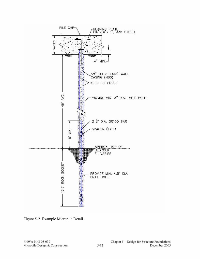
FHWA NHI-05-039 Chapter 5 – Design for Structure Foundations Micropile Design & Construction 5-12 December 2005
Figure 5-2 Example Micropile Detail.

FHWA NHI-05-039 Chapter 5 – Design for Structure Foundations Micropile Design & Construction 5-13 December 2005
Effect of Coupled Sections on Compression Capacity
As previously discussed in Chapter 3, steel reinforcing bars and casing are installed in coupled sections. For installation of micropiles in very low overhead clearance conditions, the length of individual casing sections may be 1 meter or shorter. Reinforcing bar couplers can typically provide a minimum axial capacity of 125 percent of the intact reinforcing bar yield strength, therefore the strength properties of an intact reinforcing bar can be used.
A common method for coupling individual casing lengths for micropiles is to machine a thread into the wall of the casing at the section ends. If the joint is properly designed and if the casing is filled with grout (as is commonly done), the joint can provide compressive capacity approximately equivalent to the strength of the full intact casing section. The grout provides support, preventing the male half of the joint from deforming inward.
From a practical standpoint, the strength of coupled sections of reinforcing bars and/or casing sections is confirmed via proof testing and verification testing.
Allowance for Corrosion
For evaluation of the allowable compression capacity of the cased length, the outside diameter of the steel casing is reduced to account for assumed losses in section resulting from corrosion over the design life. The specific losses depend on the agressivity of the ground in which the micropile is constructed. It is noted here, that the cross sectional area of the reinforcing bar is not reduced (for purposes of
( ) 222sin
2
222sin
22sin
.13.17.63.6.5.54
)(4
.63.6).67.4.5.5(4
67.4.)415.0(2.5.52
)(4
inininADA
inininA
ininintODID
IDODA
gcadrillholegrout
gca
w
gca
=−=−=
=−=
=−=−=
−=
ππ
π
π
( )( ) ksiksiksiF
strengthcrushinggroutFF
gcay
gcaygcay
8087,80min,min
sin
sinsin
==
=
−
−−
kipsinksiinksiP allowablec 276).63.6()80(47.0).13.17()4(4.0 22 =+=∴ −
[ ]gcagcaygroutgroutcallowablec AFAfP sinsin' 47.04.0 −−− +×=

FHWA NHI-05-039 Chapter 5 – Design for Structure Foundations Micropile Design & Construction 5-14 December 2005
calculating allowable compression capacity). Typical reinforcement coatings (e.g., epoxy-coating) and minimum specified grout cover thickness are selected to provide sufficient protection against corrosion.
Detailed information on corrosion protection for micropiles including recommended losses due to corrosion for micropiles loaded in compression is provided in Section 5.14.
Buckling of Cased Length of Micropile
In some cases, the cased length of the micropile may be formed within, for example, very weak ground or in a karstic zone. In such cases, the allowable compression load calculated above may need to be reduced to account for bucking over this length of the micropile. Section 5.20 provides information on project conditions which may require that buckling be considered and structural calculations for evaluating the allowable compression load of the cased length accounting for micropile buckling.
2) Evaluate Allowable Tension Load for Cased Length
For projects in which the micropiles will be subject to tensile loads, the allowable tension load Pt-allowable for the cased length of a micropile can be calculated as:
( )gcabarsteelyallowablet AAFP sin55.0 +×= −− (Eq. 5-2)
where Fy-steel is the minimum yield stress of the bar and casing.
Allowance for Corrosion
For aggressive ground conditions (as defined in Section 5.14), it may be conservatively assumed that the steel casing is not effective in carrying tensile loads, i.e., assume Acasing = 0 in Eq. 5-2. In this case, the central reinforcing steel should be designed to carry the entire tension design load. Detailed information on corrosion protection for micropiles loaded in tension is provided in Section 5.14.
Effect of Coupled Sections on Tensile Capacity
Unlike compressive stresses, tension stresses have a greater impact on the integrity of the casing at the joint location primarily because of the reduced thickness of the casing over the length of the threaded area. Currently, no specific testing standard

FHWA NHI-05-039 Chapter 5 – Design for Structure Foundations Micropile Design & Construction 5-15 December 2005
exists for evaluating the tension capacity of a threaded casing joint appropriate for micropile applications.
If tension loads greater than 25 percent of the allowable tension load on the intact casing are proposed to be resisted by a casing with flush joint threaded connections, the Owner should require the contractor to provide data demonstrating the adequacy of the proposed joint detail. Since a common testing method does not exist, testing procedures and test data will need to be reviewed by a qualified engineer. As projects involving micropiles subject to relatively large tensile forces become more commonplace, a means to evaluate allowable tensile stresses for threaded joints will become necessary, especially since many casing providers in the U.S. have a slightly different proprietary threading detail.
3) Evaluate Combined Axial Compression and Bending of Cased Length
The application of lateral loads or overturning moments (from the superstructure) at the ground surface create bending stresses in the micropile. These bending stresses cause additional compressive stresses (above those from vertical compression loads alone) in the micropile. Allowable stresses in the cased length of the micropile are evaluated using a combined stress evaluation.
As for other deep foundation elements subject to lateral loads and/or overturning moments, the bending moments in the pile can be evaluated using a laterally loaded pile analysis program such as LPILE (Reese et al., 2005). With these analyses, the maximum bending moment in the pile, Mmax, is calculated and used in the combined stress evaluation.
The details of performing laterally loaded micropile analyses are provided in Section 5.18. Herein, it is assumed that Mmax has been evaluated and the structural capacity of the cased length can be evaluated.
The combined stress evaluation is based on the method described in Section 10.36 of AASHTO (2002) for structural steel sections. The design check for combined stresses (appropriate for micropiles) is
0.11 '
≤
−
+
be
a
b
a
a
FFff
Ff
(Eq. 5-3)

FHWA NHI-05-039 Chapter 5 – Design for Structure Foundations Micropile Design & Construction 5-16 December 2005
where
• fa is the axial stress = Pc/Acasing; • fb is the bending stress = Mmax/S where S is the elastic section modulus of
the steel casing; • Fa is the allowable axial stress that would be permitted if axial force alone
existed = 0.47 Fy-casing (see AASHTO Table 10.32.1.A); • Fb = is the allowable bending stress that would be permitted if bending
moment alone existed = 0.55 Fy-casing (see AASHTO Table 10.32.1.A) ; and • F′e is the Euler buckling stress.
The contribution of a central reinforcing bar to bending strength is small compared to that of the casing, hence its effects on bending strength are ignored in Eq. 5-3. In Eq. 5-3, it is conservatively assumed that the maximum axial compression load, Pc, is carried by the steel casing only and the yield stress of the steel casing is used. Section properties required for the analysis are calculated as:
)(4
22sin IDODA gca −=
π (Eq. 5-4a)
( )2/sin
ODI
S gca= (Eq. 5-4b)
( )44sin 64
IDODI gca −=π (Eq. 5-4c)
The Euler buckling stress is calculated as:
( )2
2'
rKlFSEFe
π= (Eq. 5-5)
where
• E = elastic modulus of the steel casing (typically assumed to be 200,000 MPa (29,000 ksi));
• FS is a factor of safety equal to 2.12; • K = effective length factor (assumed equal to 1.0); • L = unsupported length of the micropile; and • r = radius of gyration of the steel casing = (Icasing/Acasing)1/2.

FHWA NHI-05-039 Chapter 5 – Design for Structure Foundations Micropile Design & Construction 5-17 December 2005
The effective length factor, K, depends on the rotational restraint at the ends of the micropile and the means available to resist lateral movements. This value is typically assumed equal to 1.0 for micropile designs.
The assumption that the entire axial load is carried by the steel casing is conservative. Richards and Rothbauer (2004) proposed a combined stress check that can account for the contribution of the grout inside the casing to compression capacity. This method assumes that buckling potential is negligible. The Richards and Rothbauer combined stress check can be written as:
0.1max ≤+− allowableallowablec
c
MM
PP (Eq. 5-6)
where
• Pc = maximum axial compression load; • Pc-allowable is determined from Eq. 5-1; • Mmax = maximum bending moment in the micropile; and • Mallowable = Fb (=0.55 Fy-casing) × S.
More advanced methods which consider composite action between the steel casing and the grout inside the casing in carrying these axial loads could be used, but are beyond the scope of this manual.
5.7 STEP 6: STRUCTURAL DESIGN OF MICROPILE UNCASED LENGTH
The allowable compression load for the uncased length of a micropile is given as:
( )barbarygroutcallowablec AFAfP ×+×= −− 47.04.0 ' (Eq. 5-7)
For the uncased portion of the pile, the reinforcing bar yield stress used in the calculations in compression is assumed to not exceed 600 MPa (87 ksi) (i.e., to prevent grout crushing at an assumed strain of 0.003 unless data is provided demonstrating that the confined grout can sustain higher strain levels without crushing).
The allowable tension load for the uncased length of a micropile is given as:
barbaryallowablet AFP ×= −− 55.0 (Eq. 5-8)

FHWA NHI-05-039 Chapter 5 – Design for Structure Foundations Micropile Design & Construction 5-18 December 2005
In Eq. 5-8, the actual yield stress of the bar is used.
It is noted that a combined stress evaluation (see Step 5 Part 3) is not performed for the uncased length since micropiles are designed so that bending stresses are negligible within the uncased portion of the micropile. In other words, the steel casing will be placed to a sufficient depth so that bending moments below that depth are negligible.
5.8 STEP 7: REVISE MICROPILE DESIGN
Based on the calculations performed in Steps 5 and 6, the micropile cross section should be modified if the allowable compression or tension load (for either the cased or uncased length) is not sufficient to carry the compression or tension design loads provided as part of Step 3. Possible modifications include using more micropiles, increasing the size of the drill hole, using a larger diameter reinforcing bar, replacing a single reinforcing bar with two bars, and/or increasing the steel area of the casing.
5.9 STEP 8. EVALUATE GEOTECHNICAL CAPACITY OF MICROPILE
5.9.1 Establish Stratum for Bond Zone
The maximum compression and tension loads applied at the top of the micropile must be resisted through grout to ground bond over a specific length of the micropile. This length is referred to as the bond zone or bond length. This length can be formed in most soil and rock strata with the major differences being in the grout to ground bond strength that can be developed in a given ground type. The objective for design is to evaluate the length of this bond zone required to resist the applied tension and compression loads with a prescribed factor of safety (discussed subsequently).
As part of this design step, all borings should be reviewed to identify strata appropriate for the micropile bond zone and to identify significant variations in subsurface conditions. Like ground anchors, certain soil deposits are not generally suitable as the location for the micropile bond zone, including (1) organic soils; (2) cohesive soils with an average liquidity index greater than 0.2; (3) cohesive soils with an average liquid limit greater than 50; and (4) cohesive soils with an average plastic index greater than 20. Micropiles installed in these deposits may be

FHWA NHI-05-039 Chapter 5 – Design for Structure Foundations Micropile Design & Construction 5-19 December 2005
susceptible to excessive creep deformations at testing and working loads. If used, however, for the bond zone, comprehensive testing is recommended and higher factors of safety for geotechnical capacity should be used, as discussed subsequently.
5.9.2 Select Ultimate Bond Stress and Calculate Bond Length
The allowable geotechnical bond capacity, PG-allowable, is calculated as:
bbbond
allowableG LDFS
P ×××=− πα
(Eq. 5-9)
where: αbond = grout to ground ultimate bond strength; FS = factor of safety applied to the ultimate bond strength; Db = diameter of the drill hole; and Lb = bond length
In most cases, Eq. 5-9 will be used to calculate the estimated bond length to resist the maximum compression load and/or maximum tension (i.e., uplift) load based on load information provided as part of Step 3. To this end, Eq. 5-9 can be rearranged as:
bbond
allowableGb D
FSPL
××
×= −
πα (Eq. 5-10)
where, for Eq. 5-10, PG-allowable is equal to the maximum compression or tension load for design.
Table 5-3 provides guidance for estimating the values for grout-to-ground ultimate bond strengths. The table includes ranges for the four methods of grouting (Type A, Type B, Type C, and Type D) in a variety of ground conditions.
For most micropile projects, the contract documents will provide a minimum bond length. This bond length will be based on the evaluation provided in Eq. 5-10. Unless the design engineer has previous experience in similar ground, values no greater than average values (i.e., middle of range reported) for αbond from Table 5-3 should be used. The design engineer may wish to consider lower bound values where granular materials are loose or for medium to high plasticity cohesive materials. Although the specific type of micropile (i.e., Type A, B, C, or D) will be selected by the Contractor, the design engineer should assume a Type A micropile

FHWA NHI-05-039 Chapter 5 – Design for Structure Foundations Micropile Design & Construction 5-20 December 2005
will be constructed for microple bond zones in rock and a Type B micropile will be constructed for bond zones in soil.
Ranges of values provided in Table 5-3 and additional information on estimating grout-to-ground bond capacities is available in the following publications:
• “GEC No. 4, Ground Anchors and Anchored Structures”, FHWA Report No. FHWA-IF-99-015, (1999).
• “Post-Tensioning Institute (PTI) Recommendations for Prestressed Rock and Soil Anchors”, (2004).
• “Construction, Carrying Behavior, and Creep Characteristics of Ground Anchors,” H. Ostermayer, Conference on Diaphragm Walls and Anchorages, Institute of Civil Engineers, London, (1975).
• “Ground Control and Improvement” by P.P. Xanthakos, L.W. Abramson, and D.A. Bruce, (1994).
• “Drilled and Grouted Micropiles State-of-the-Practice Review”, FHWA Report Nos. RD-96-016/017/018/019; Volumes I – IV, (1997).
• “Tiebacks”, FHWA Report No. FHWA/RD-82/047, (1982). • “Permanent Ground Anchors”, FHWA Report No. FHWA-DP-68-1R,
(1988).

FHWA NHI-05-039 Chapter 5 – Design for Structure Foundations Micropile Design & Construction 5-21 December 2005
Table 5-3. Summary of Typical αbond (Grout-to-Ground Bond) Values for Micropile Design.
Grout-to-Ground Bond Ultimate Strengths, kPa (psi) Soil / Rock Description
Type A Type B Type C Type D
Silt & Clay (some sand) (soft, medium plastic)
35-70 (5-10)
35-95 (5-14)
50-120 (5-17.5)
50-145 (5-21)
Silt & Clay (some sand) (stiff, dense to very dense)
50-120 (5-17.5)
70-190 (10-27.5)
95-190 (14-27.5)
95-190 (14-27.5)
Sand (some silt) (fine, loose-medium dense)
70-145 (10-21)
70-190 (10-27.5)
95-190 (14-27.5)
95- 240 (14-35)
Sand (some silt, gravel) (fine-coarse, med.-very dense)
95-215 (14-31)
120-360 (17.5-52)
145-360 (21-52)
145-385 (21-56)
Gravel (some sand) (medium-very dense)
95-265 (14-38.5)
120-360 (17.5-52)
145-360 (21-52)
145-385 (21-56)
Glacial Till (silt, sand, gravel) (medium-very dense, cemented)
95-190 (14-27.5)
95-310 (14-45)
120-310 (17.5-45)
120-335 (17.5-48.5)
Soft Shales (fresh-moderate fracturing, little to no weathering)
205-550 (30-80) N/A N/A N/A
Slates and Hard Shales (fresh-moderate fracturing, little to no weathering)
515-1,380 (75-200) N/A N/A N/A
Limestone (fresh-moderate fracturing, little to no weathering)
1,035-2,070 (150-300) N/A N/A N/A
Sandstone (fresh-moderate fracturing, little to no weathering)
520-1,725 (75.5-250) N/A N/A N/A
Granite and Basalt (fresh-moderate fracturing, little to no weathering)
1,380-4,200 (200-609) N/A N/A N/A
Type A: Gravity grout only Type B: Pressure grouted through the casing during casing withdrawal Type C: Primary grout placed under gravity head, then one phase of secondary “global” pressure grouting Type D: Primary grout placed under gravity head, then one or more phases of secondary “global” pressure
grouting

FHWA NHI-05-039 Chapter 5 – Design for Structure Foundations Micropile Design & Construction 5-22 December 2005
For all highway projects, some amount of site-specific load testing of micropiles must be performed and the scope of this load testing is used to define the factor of safety applied to the ultimate bond strength for design. Herein, a factor of safety of 2.0 is recommended provided the following load testing is performed:
• At least one ultimate or verification test is conducted prior to beginning production micropile installation, and then one or more additional ultimate or verification tests must be conducted in each significantly different ground type encountered as construction proceeds. A larger number of ultimate, or verification, tests may be specified for larger projects.
• During installation of production micropiles, proof testing must be
conducted on a specified number of the total production piles installed. In general, proof tests may be performed on 5 percent of production micropiles. Specific proof testing requirements are discussed in Chapter 7.
For projects in which the micropile bond zone is formed in potentially creeping soils, high plasticity soils, weak rock, or any other ground type considered to be marginal or for which previous experience in similar ground is limited, a factor of safety value of 2.5 should be used to estimate the bond length and as the basis for the maximum load in an ultimate or verification load test. For micropiles installed in soils susceptible to creep, load testing will include measuring micropile deformations during an extended period of time at one or more test loads. The measured movement is compared to a maximum allowable creep movement (see Chapter 7 for details on sustained load (creep) testing).
5.9.3 Evaluate Micropile Group Compression Capacity
Micropile Groups in Cohesive Soils
The efficiency of a micropile group installed in cohesive soils is a function of the center-to-center spacing of the micropiles, s, and contact condition between the bottom of the micropile footing cap and the soil near the ground surface (see Table 5-4).
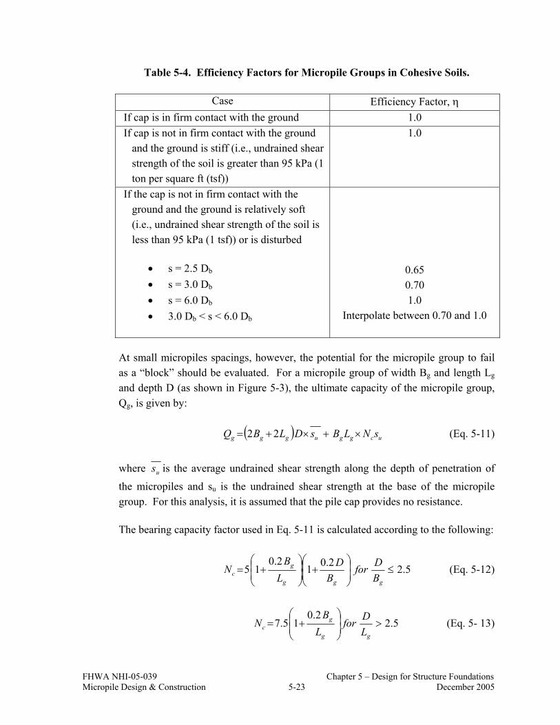
FHWA NHI-05-039 Chapter 5 – Design for Structure Foundations Micropile Design & Construction 5-23 December 2005
Table 5-4. Efficiency Factors for Micropile Groups in Cohesive Soils.
Case Efficiency Factor, η If cap is in firm contact with the ground 1.0 If cap is not in firm contact with the ground
and the ground is stiff (i.e., undrained shear strength of the soil is greater than 95 kPa (1 ton per square ft (tsf))
1.0
If the cap is not in firm contact with the ground and the ground is relatively soft (i.e., undrained shear strength of the soil is less than 95 kPa (1 tsf)) or is disturbed
• s = 2.5 Db • s = 3.0 Db • s = 6.0 Db • 3.0 Db < s < 6.0 Db
0.65 0.70 1.0
Interpolate between 0.70 and 1.0
At small micropiles spacings, however, the potential for the micropile group to fail as a “block” should be evaluated. For a micropile group of width Bg and length Lg and depth D (as shown in Figure 5-3), the ultimate capacity of the micropile group, Qg, is given by:
( ) ucgguggg sNLBsDLBQ ×+×+= 22 (Eq. 5-11)
where us is the average undrained shear strength along the depth of penetration of
the micropiles and su is the undrained shear strength at the base of the micropile group. For this analysis, it is assumed that the pile cap provides no resistance.
The bearing capacity factor used in Eq. 5-11 is calculated according to the following:
5.22.012.0
15 ≤
+
+=
ggg
gc B
DforB
DL
BN (Eq. 5-12)
5.22.0
15.7 >
+=
gg
gc L
DforL
BN (Eq. 5- 13)

FHWA NHI-05-039 Chapter 5 – Design for Structure Foundations Micropile Design & Construction 5-24 December 2005
Figure 5-3. Block Failure Model for Micropile Group in Cohesive Soil with Cap in Contact with Ground.
Qg
Cap
Bg
Lg
Cohesive soilwith c=su and
φ=0
Block shear
surface
D

FHWA NHI-05-039 Chapter 5 – Design for Structure Foundations Micropile Design & Construction 5-25 December 2005
The group capacity to be used for design is evaluated using the following steps:
Step 1: Calculate ultimate group capacity as:
( ) ηπα ×××××= groupinmicropilesofnoLDQ bbbondg . (Eq. 5-14)
where η is obtained from Table 5-4.
Step 2: Calculate ultimate group capacity according to Eq. 5-14 and use lower value (i.e., from Step 1 and Step 2) for design.
Step 3: Use a FS value of 2.0 to calculate an allowable group capacity.
Micropile Groups in Cohesionless Soils
As long as the center-to-center spacing of micropiles in a group is greater than three times the diameter of the grouted body (i.e., s > 3Db), the capacity of a micropile group in cohesionless soils may be calculated as the sum of the resistance of all the individual micropiles in the group, i.e., use Eq. 5-14 with η=1.0. For example, for pressure grouted micropiles installed in cohesionless soils with a typical grouted diameter of 200 mm and typical minimum center-to-center spacing in the range of 750 to 1,000 mm, it is therefore unnecessary to consider a reduction in micropile capacity as a result of group effects.
For the case of micropiles installed in strong soil (which may be cohesionless soil) over weak or compressible soil, an alternate method to evaluate micropile group capacity is used, as described below.
Micropile Groups in Strong Soil Overlying a Weak or Compressible Soil
If a micropile group is embedded in a strong soil deposit overlying a weaker soil deposit, then the potential for a “punching” shear failure of the micropile group into the weaker soil stratum should be considered during design.
The method proposed herein to evaluate the potential for punching shear failure of micropile groups is the same as that which has been developed to address this same issue for drilled shaft groups (see FHWA-IF-99-025, 1999). This approach requires that the capacity of the block of micropiles meet the following condition to assure safety against punching shear failure:

FHWA NHI-05-039 Chapter 5 – Design for Structure Foundations Micropile Design & Construction 5-26 December 2005
[ ] 1110qqq
BHqq
LBQ
og
opgg
g ≤−+≤= (Eq. 5-15)
where:
• Qg, Bg, and Lg are as defined on Figure 5-3; • qo is the ultimate unit base resistance at the depth of the top of the lower (i.e.,
weaker) layer using the shear strength parameters of the lower layer; • q1 is the ultimate unit base resistance at the depth of the top of the upper (i.e.,
stronger) layer using the shear strength parameters of the upper layer; • qp is the ultimate unit base resistance at the depth of the micropile tips; and • H is the distance from the tip elevation of the micropiles to the elevation of
the top of the weaker lower soil layer.
If the piles are battered, the values for Bg and Lg should be based on the plan area of the pile group at the base of the piles. Satisfaction of the condition prescribed in Eq. 5-15 should preclude the potential for a punching shear failure of the micropile group (see Figure 5-4).
Figure 5-4. End-bearing Resistance of Piles in Layered Soils (after Meyerhof, 1976).
D
H
qo
qp
q1
Pile toe 10Bg
Weak Soil
Strong
Weak Soil

FHWA NHI-05-039 Chapter 5 – Design for Structure Foundations Micropile Design & Construction 5-27 December 2005
5.9.4 Evaluate Micropile Group Uplift Capacity
The design of micropile groups subject to uplift forces follows the method described in FHWA NHI-05-042 (2005) for uplift capacity for driven piles in cohesionless soils and for driven piles in cohesive soils.
Micropile Groups in Cohesive Soils
For micropile groups in cohesive soil, the group uplift capacity may be calculated based upon the undrained shear strength of the block of soil enclosed by the group plus the effective weight of the pile cap and pile-soil block as shown on Figure 5-5. This may be expressed as:
( ) guug WsYXZQ +×+×=2 (Eq. 5-16)
where us is the average undrained soil shear strength over the depth of micropile
embedment along the group perimeter and Wg is the effective weight of the pile/soil block including the pile cap. In using Eq. 5-16, a factor of safety of 2.0 should be used to estimate the allowable group uplift capacity.
Figure 5-5. Model to Calculate Micropile Group Uplift Capacity in Cohesive Soils.

FHWA NHI-05-039 Chapter 5 – Design for Structure Foundations Micropile Design & Construction 5-28 December 2005
Micropile Groups in Cohesionless Soils
The uplift capacity of a micropile group in cohesionless soil may be conservatively taken as the effective weight of a block of soil extending upward from the base of the micropiles at a slope of 1H:4V as shown on Figure 5-6. In this evaluation, the weight of the micropiles within the block is (conservatively) considered equal to the weight of the soil. Using Figure 5-6, the group uplift capacity is given by:
( ) γ×
××++×= DAAAAQ topbasetopbaseug 31 (Eq. 5-17)
where Abase = Bg × Lg and Atop = (Bg+D/2) × (Lg+D/2) and γ is the effective unit weight of the soil. In Eq. 5-17, the term in brackets is simply the volume of the enclosed soil. A FS = 1.0 is acceptable for this analysis since the shear strength that would be mobilized within the soil is conservatively neglected; this implies that the allowable micropile group capacity would be equal to the calculated group uplift capacity based on Eq. 5-17.
The allowable group uplift capacity (based on either Eq. 5-16 or 5-17) should be compared to the allowable uplift capacity of a single micropile multiplied by the number of micropiles in the group and the design should be based on the lesser group capacity.
Figure 5-6. Model to Calculate Micropile Group Uplift Capacity in Cohesionless Soils.

FHWA NHI-05-039 Chapter 5 – Design for Structure Foundations Micropile Design & Construction 5-29 December 2005
5.10 STEP 9. ESTIMATE MICROPILE GROUP SETTLEMENT
5.10.1 General
In general, methods used for estimating settlements of driven pile groups are applicable for micropile groups. The major components of settlement that need to be assessed include: (1) settlements of the ground in which the micropiles are constructed; and (2) elastic compression/tension of an individual micropile. These settlements are added together to evaluate the total settlement of the micropile group subject to the design load and are then compared to the allowable settlement.
The specific value for allowable settlement will depend on the structure being supported, but for typical highway bridge projects, the maximum vertical movement will depend primarily on anticipated differential settlements between bridge piers for single span or continuous span bridges.
5.10.2 Micropile Group Settlement
Micropiles in a group can undergo vertical displacement as a result of consolidation of soil layers below the bottom of the micropile group. Where a single pile will transfer its load to the soil in the immediate vicinity of the pile, a pile group can distribute its load to the soil layer below the group. Consideration should be made for this group displacement when the soil below the group is cohesive in nature and subject to consolidation. The method presented herein for evaluating micropile group settlements is similar to that for driven piles (see FHWA-NHI-05-042, 2005).
For purposes of calculating settlements of micropile groups in soil (for which loads are primarily transferred through side resistance), loads are assumed to act on an equivalent footing located at two-thirds of the depth of embedment of the micropiles into the layer that provides support (i.e., two-thirds of the depth of the micropile bond zone). This concept is illustrated in Figure 5-7 for a uniform soil profile and Figure 5-8 for a micropile bond zone formed in firm or strong layer that is overlain by an upper soft or weak layer (which is common for many micropile applications). Where a clayey layer may exist just below the tips of the micropiles, the equivalent footing is assumed to exist at the depth corresponding to 8/9 of the length of the bond zone. The reader is referred to FHWA-NHI-05-042 (FHWA, 2005) for additional information on the equivalent footing concept. For a pile group consisting of only vertical piles, the equivalent footing has a plan area that corresponds to the perimeter dimensions of the pile group.

FHWA NHI-05-039 Chapter 5 – Design for Structure Foundations Micropile Design & Construction 5-30 December 2005
Figure 5-7. Equivalent Footing Concept for Uniform Soil (after FHWA-NHI-05-042, 2005).
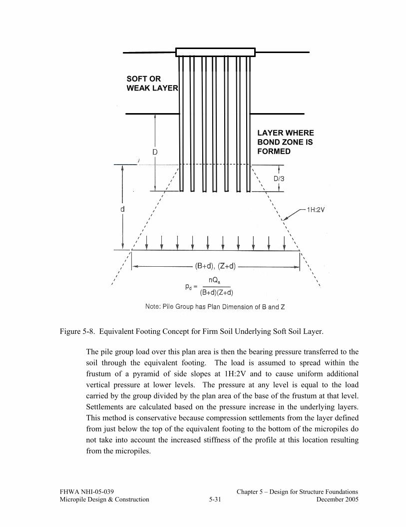
FHWA NHI-05-039 Chapter 5 – Design for Structure Foundations Micropile Design & Construction 5-31 December 2005
SOFT ORWEAK LAYER
LAYER WHEREBOND ZONE ISFORMED
SOFT ORWEAK LAYER
LAYER WHEREBOND ZONE ISFORMED
Figure 5-8. Equivalent Footing Concept for Firm Soil Underlying Soft Soil Layer.
The pile group load over this plan area is then the bearing pressure transferred to the soil through the equivalent footing. The load is assumed to spread within the frustum of a pyramid of side slopes at 1H:2V and to cause uniform additional vertical pressure at lower levels. The pressure at any level is equal to the load carried by the group divided by the plan area of the base of the frustum at that level. Settlements are calculated based on the pressure increase in the underlying layers. This method is conservative because compression settlements from the layer defined from just below the top of the equivalent footing to the bottom of the micropiles do not take into account the increased stiffness of the profile at this location resulting from the micropiles.

FHWA NHI-05-039 Chapter 5 – Design for Structure Foundations Micropile Design & Construction 5-32 December 2005
Where clayey soils may consolidate as a result of micropile group loading, nominally undisturbed tube samples should be collected from potential consolidating layers and consolidation tests should be performed to assess compressibility parameters and stress history information for the consolidating layer. The reader is referred to GEC No. 5 for specific information on consolidation testing and parameter evaluation. For micropile group settlements in cohesionless layers, SPT data is used to estimate compression parameters.
Step By Step Procedure for Micropile Group Settlement In Cohesive Soils
Step 1: Determine the new load imposed on soil by the pile group.
a. Determine the location of the equivalent footing using Figure 5-7 or 5-8. b. Determine the dimensions of the equivalent footing. For pile groups
consisting only of vertical piles, the equivalent footing has the same dimensions as the length and width of the pile group from Figure 5-7. For pile groups that include batter piles, the plan area of the footing should be calculated from the dimensions of the pile group at depth 2/3 D, including the plan area increase due to the pile batter.
c. Determine the pressure distribution to soil layers below the equivalent
footing up to the depth at which the pressure increase from the equivalent footing is less than 10% of existing effective overburden pressure at that depth. The depth at which the pressure increase is less than 10% will provide the total thickness of cohesive soil layer or layers to be used in performing settlement computations. Note that the group design load should be used in determining the pressure distribution for settlement computations, and not the ultimate group load.
d. Divide the cohesive soil layers in the affected pressure increase zone into
several thinner layers of 1.5 to 3 meter (5 to 10 ft) thickness. The thickness of each layer is the thickness H for the settlement computation for that layer.
e. Determine the existing effective overburden pressure, po, at midpoint of
each layer.

FHWA NHI-05-039 Chapter 5 – Design for Structure Foundations Micropile Design & Construction 5-33 December 2005
f. Determine the imposed pressure increase, ∆p, at midpoint of each affected soil layer based on the appropriate pressure distribution.
Step 2: Determine consolidation test parameters.
Step 3: Compute settlements.
Using an appropriate settlement equation, compute the settlement of each affected soil layer. Sum the settlements of all layers to obtain the total estimated soil settlement from the pile group.
Step By Step Procedure for Micropile Group Settlement In Cohesionless Soils
Pile groups supported in and underlain by cohesionless soils will produce only immediate settlements implying that the settlements will occur immediately as the pile group is loaded. A procedure to calculate pile group settlements in cohesionless soils is provided below.
Step 1: Determine the new load imposed on soil by the pile group.
a. Determine the location of the equivalent footing using Figure 5-7 or 5-8. b. Determine the dimensions of the equivalent footing. c. Determine the pressure distribution to soil layers below the equivalent
footing up to the depth at which the pressure increase from the equivalent footing is less than 10% of existing effective overburden pressure at that depth.
d. Divide the soil layers in the affected pressure increase zone into several
thinner layers of 1.5 to 3 meter (5 to 10 ft) thickness. The thickness of each layer is the thickness H for the settlement computation for that layer.
e. Determine the existing effective overburden pressure, po, at midpoint of
each layer.
f. Determine the imposed pressure increase, ∆p, at midpoint of each affected soil layer based on the appropriate pressure distribution.

FHWA NHI-05-039 Chapter 5 – Design for Structure Foundations Micropile Design & Construction 5-34 December 2005
Step 2: Determine bearing capacity index for each cohesionless layer.
Determine the average corrected (for overburden pressure and hammer efficiency) SPT N160 value for each cohesionless layer. Use N160 in Figure 5-9 to obtain the bearing capacity index, C′ for each layer.
Step 3: Compute settlements.
Compute the settlement of each affected soil layer under the applied load using the following formula:
∆+=∆
o
oo p
ppC
HH log1' (Eq. 5-18)
Sum the settlements of all layers to obtain the total estimated soil settlement from the pile group. If a layered soil profile is within the compressible zone being considered, the two methods previously described for cohesive and cohesionless soils can be used separately for the appropriate layers and then settlements form each layer added to obtain the total settlement from the pile group.

FHWA NHI-05-039 Chapter 5 – Design for Structure Foundations Micropile Design & Construction 5-35 December 2005
(Note: The “Inorganic SILT” curve should generally not be applied to soils that exhibit plasticity)
Figure 5-9. Bearing Capacity Index versus Corrected SPT Blowcount (modified after Hough, 1959).
Corrected SPT N-value, N160
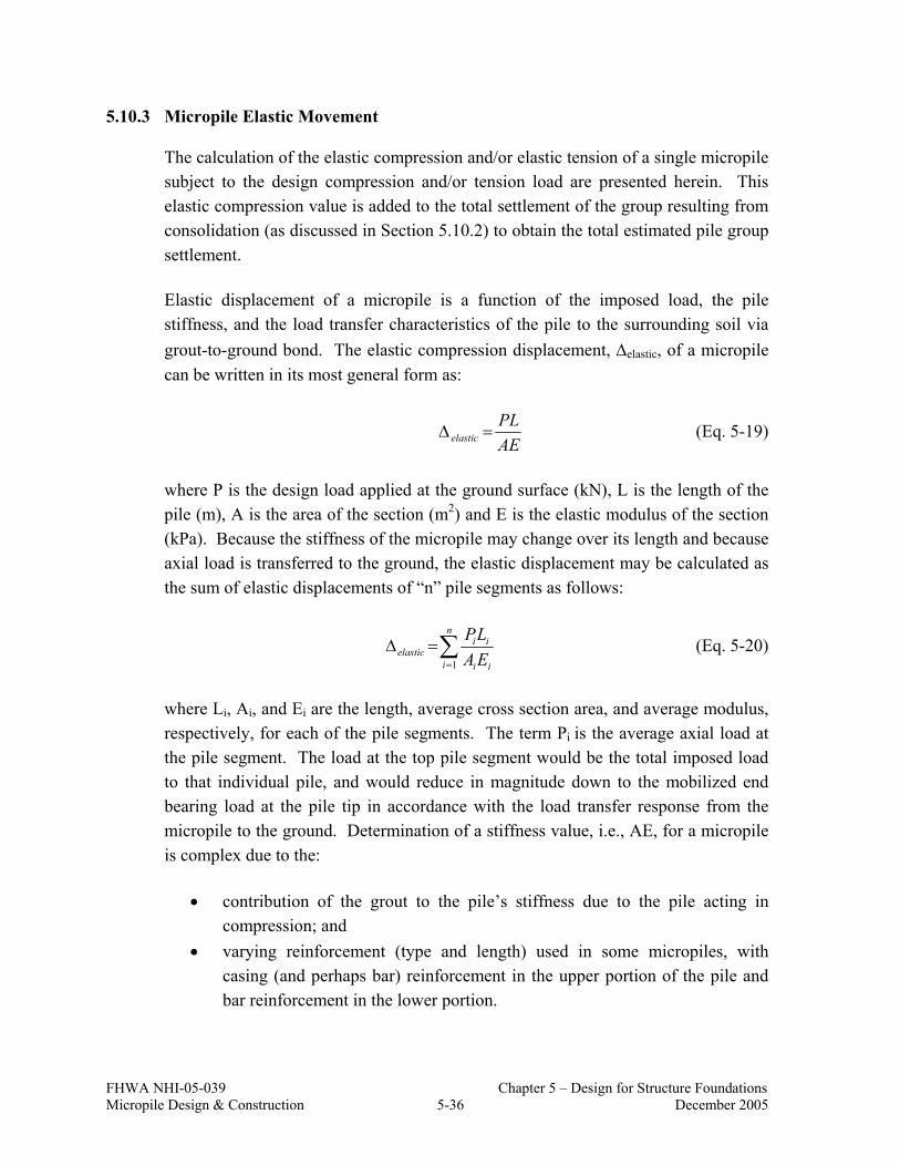
FHWA NHI-05-039 Chapter 5 – Design for Structure Foundations Micropile Design & Construction 5-36 December 2005
5.10.3 Micropile Elastic Movement
The calculation of the elastic compression and/or elastic tension of a single micropile subject to the design compression and/or tension load are presented herein. This elastic compression value is added to the total settlement of the group resulting from consolidation (as discussed in Section 5.10.2) to obtain the total estimated pile group settlement.
Elastic displacement of a micropile is a function of the imposed load, the pile stiffness, and the load transfer characteristics of the pile to the surrounding soil via grout-to-ground bond. The elastic compression displacement, ∆elastic, of a micropile can be written in its most general form as:
AEPL
elastic =∆ (Eq. 5-19)
where P is the design load applied at the ground surface (kN), L is the length of the pile (m), A is the area of the section (m2) and E is the elastic modulus of the section (kPa). Because the stiffness of the micropile may change over its length and because axial load is transferred to the ground, the elastic displacement may be calculated as the sum of elastic displacements of “n” pile segments as follows:
∑=
=∆n
i ii
iielastic EA
LP1
(Eq. 5-20)
where Li, Ai, and Ei are the length, average cross section area, and average modulus, respectively, for each of the pile segments. The term Pi is the average axial load at the pile segment. The load at the top pile segment would be the total imposed load to that individual pile, and would reduce in magnitude down to the mobilized end bearing load at the pile tip in accordance with the load transfer response from the micropile to the ground. Determination of a stiffness value, i.e., AE, for a micropile is complex due to the:
• contribution of the grout to the pile’s stiffness due to the pile acting in compression; and
• varying reinforcement (type and length) used in some micropiles, with casing (and perhaps bar) reinforcement in the upper portion of the pile and bar reinforcement in the lower portion.

FHWA NHI-05-039 Chapter 5 – Design for Structure Foundations Micropile Design & Construction 5-37 December 2005
For estimates of displacement caused by compression loads, the stiffness of the composite section at a given point in the pile can be evaluated using the formula:
[ ] [ ]steelsteelgroutgroutpile EAEAEA ×+×= (Eq. 5-21)
For estimates of displacement caused by tension loads, the stiffness of the composite section can be evaluated using the formula:
[ ]steelsteelpile EAEA ×= (Eq. 5-22)
The value for Egrout can be quite variable, but for design calculations may be estimated as Egrout (MPa) = 4732 × (f′
c (MPa))1/2 (Egrout (ksi) = 57 × (f′c (psi))1/2).
A conservative approach to calculate elastic displacement is to assume that no load is transferred to the ground over the length of the micropile from the top of the micropile to the top of the bond zone; this implies that the elastic compression of this length of the micropile can be calculated according to Eq. 5-19 with P equal to the design load and L equal to the length of the micropile above the bond zone. If there are changes in the micropile cross section over that length (e.g., section with just reinforcing bar and section with reinforcing bar and casing), then Equation 5-20 is used with pile segment lengths defined based on changes in cross section.
In the bond zone, the cross section of the micropile will usually be constant. Therefore, since it is assumed that the design load is carried uniformly over the length of the bond zone in side resistance; the elastic displacement along this length of the micropile can be calculated using Eq. 5-19 with P equal to the design load and L equal to one-half the length of the bond zone.
For micropiles bonded in rock or for end-bearing micropiles on rock, the full length of the micropile above the top of rock should be assumed for the elastic length. It is noted that the assumption of the lengths over which elastic movements occur can be confirmed via load testing in which loads are incrementally cycled (similar to a ground anchor performance test) to allow for measurement of the elastic movement.
An example calculation of elastic compression and tension displacement for a micropile is provided in Sample Problem No. 1.

FHWA NHI-05-039 Chapter 5 – Design for Structure Foundations Micropile Design & Construction 5-38 December 2005
5.11 STEP 10. DESIGN MICROPILE CONNECTION AT PILE CAP
Unless a single micropile is used to support a load, a pile cap (footing) is necessary to spread the structure loads and any overturning moments to all the micropiles in the group. Reinforced concrete pile caps are designed in accordance with the AASHTO Standard Specifications for Highway Bridges and individual DOTs may have minimum requirements for pile caps (e.g., minimum concrete cover, minimum embedment of pile top into cap). The structural design of reinforced concrete pile caps is not addressed in this manual.
The connection between the top of the micropiles and the reinforced concrete pile cap can vary depending on the required capacity of the connection, the type of micropile reinforcement, and the details of the pile cap. Seven examples of the pile-to-footing connections are shown in Figures 5-10 through 5-16. Figures 5-10 through 5-13 show typical connections for piles that can have both tension and compression loads depending on load case. Figures 5-14 through 5-16 show simple connections for piles that are only in compression.
Figure 5-10 shows a composite reinforced micropile connected to a new (or extended) footing. The footing tension and compression load is transferred to the pile through the top bearing plate. The stiffener plates provide bending strength to the plate, plus provide additional weld length for transferring the load from the bearing plate to the pile casing. The stiffener plates can be eliminated if the support of the top plate and additional weld length are not required. Additional considerations for this connection detail include the following:
• The portion of the tension load carried by the reinforcing bar can be transferred to the top plate through the nut, reducing the plate-to-casing weld requirement.
• The bond between the pile casing and the footing concrete can be utilized, reducing the load capacity required for the top plate and top plate to casing weld.
• A portion of the compression load can be transferred from the top plate to the casing through bearing, reducing the weld capacity requirement. This requires a higher level of quality for the fabrication of the bearing surface between the casing and the plate.
Sample Problem No. 1 includes the design of a pile connection similar to that shown in Figure 5-10. The additional considerations listed above are not included in the sample problem calculations.

FHWA NHI-05-039 Chapter 5 – Design for Structure Foundations Micropile Design & Construction 5-39 December 2005
EXISTING FOOTING
EXTENDED FOOTINGREINFORCING
BAR W/NUT
BEARING PLATEAS REQUIRED
STIFFNERPLATE (TYP)
BOTTOM OFFOOTING ELEV. STEEL CASING
TYP
Figure 5-10. Pile to Footing Connection Detail (compression and tension loads).
Figure 5-11 shows a composite reinforced micropile connected to an existing footing. The pile is installed through an oversized hole cored through the existing footing or slab. After the pile is installed, the annulus between the core hole and the micropile is cleaned (usually via pressure washing) and filled with non-shrink cement grout. Steel rings are welded to the top section of the casing prior to pile installation. These rings transfer the pile load from the casing to the non-shrink grout. Adequate spacing must be used between the rings to avoid combining bearing stresses in the concrete and grout. The total capacity of the connection is controlled by the sum of the bearing strength of the rings, the capacity of the load transfer across the interface between the non-shrink grout and the existing concrete, and the shear capacity of the existing concrete.
Grooves may be chipped into sides of the core hole (typical dimension = 20 mm deep and 32 mm wide (3/4 in. deep and 1 ¼ in. wide)) to increase the load carrying capacity of the grout to existing concrete. Also, vertical reinforcing bars may be
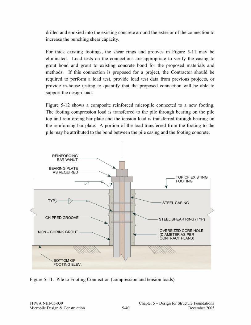
FHWA NHI-05-039 Chapter 5 – Design for Structure Foundations Micropile Design & Construction 5-40 December 2005
drilled and epoxied into the existing concrete around the exterior of the connection to increase the punching shear capacity.
For thick existing footings, the shear rings and grooves in Figure 5-11 may be eliminated. Load tests on the connections are appropriate to verify the casing to grout bond and grout to existing concrete bond for the proposed materials and methods. If this connection is proposed for a project, the Contractor should be required to perform a load test, provide load test data from previous projects, or provide in-house testing to quantify that the proposed connection will be able to support the design load.
Figure 5-12 shows a composite reinforced micropile connected to a new footing. The footing compression load is transferred to the pile through bearing on the pile top and reinforcing bar plate and the tension load is transferred through bearing on the reinforcing bar plate. A portion of the load transferred from the footing to the pile may be attributed to the bond between the pile casing and the footing concrete.
REINFORCINGBAR W/NUT
BEARING PLATEAS REQUIRED
TYP
TOP OF EXISTINGFOOTING
STEEL CASING
STEEL SHEAR RING (TYP)
NON – SHRINK GROUT
CHIPPED GROOVE
BOTTOM OFFOOTING ELEV.
OVERSIZED CORE HOLE(DIAMETER AS PERCONTRACT PLANS)
Figure 5-11. Pile to Footing Connection (compression and tension loads).

FHWA NHI-05-039 Chapter 5 – Design for Structure Foundations Micropile Design & Construction 5-41 December 2005
NEW FOOTING
BEARING PLATEAS REQUIRED
STEEL CASING
BOTTOM OFFOOTING ELEV.
FULL HEX NUT
½ HEX NUT
REINFORCING BAR
BEARING PLATE(OPTIONAL)
Figure 5-12. Pile to Footing Connection (compression and tension loads).
Figure 5-13 shows a bar-reinforced micropile cast into a new footing. The compression and tension load is transferred to the pile through bearing on the bar plate, and through bond between the footing concrete and the reinforcing bar. Competency of the construction joint between the pile grout and footing concrete is an important quality consideration for this pile type.

FHWA NHI-05-039 Chapter 5 – Design for Structure Foundations Micropile Design & Construction 5-42 December 2005
NEW FOOTING
BEARING PLATEAS REQUIRED
BOTTOM OFFOOTING ELEV.
FULL HEX NUT
½ HEX NUT
REINFORCING BAR
NEW FOOTING
BEARING PLATEAS REQUIRED
BOTTOM OFFOOTING ELEV.
FULL HEX NUT
½ HEX NUT
REINFORCING BAR
Figure 5-13. Pile to Footing Connection (compression and tension loads).
Figure 5-14 shows a typical compression connection for a moderately loaded micropile where concrete bearing stress on the pile top is within AASHTO limits (see AASHTO Section 8.15.2.1.3). Figure 5-15 shows a typical compression connection for a heavily loaded micropile where a bearing plate welded to the casing is required for concrete bearing stress on the pile top to be within AASHTO limits.

FHWA NHI-05-039 Chapter 5 – Design for Structure Foundations Micropile Design & Construction 5-43 December 2005
NEW FOOTING
STEEL CASING
BOTTOM OFFOOTING ELEV.
150 mm
Figure 5-14. Pile to New Footing Connection Detail used for Moderate Loads (compression loads).
NEW FOOTING
STEEL CASING
BOTTOM OFFOOTING ELEV.
BEARING PLATE
Figure 5-15. Pile to New Footing Connection Detail used for High Loads (compression loads).

FHWA NHI-05-039 Chapter 5 – Design for Structure Foundations Micropile Design & Construction 5-44 December 2005
Figure 5-16 shows a compression connection for a pile through an existing footing. The bond of the non-shrink grout to the footing is a function of the proposed methods (cored hole, down-the-hole hammered hole, etc.) and materials (non-shrink grout, existing concrete, etc.). Connection load tests are appropriate to verify the design.
STEEL CASING
BOTTOM OFFOOTING ELEV.
EXISTINGFOOTING
NON-SHRINKGROUT
Figure 5-16. Pile to Existing Footing Connection Detail (compression loads).
5.12 STEP 11. DEVELOP LOAD TESTING PROGRAM
Section 7.6 of this Manual provides specific information on the evaluations to be performed as part of the development of a load testing program. Of primary importance is that the scope of the load testing program be consistent with the selected factor of safety for the grout/ground bond strength used for geotechnical capacity evaluations. In Section 5.9.2, the minimum requirements for verification and proof testing were described which are consistent with a factor of safety of 2.0.
For load testing, maximum test loads should not exceed 80 percent of the ultimate structural capacity of the micropile. The ultimate structural capacity is given by:

FHWA NHI-05-039 Chapter 5 – Design for Structure Foundations Micropile Design & Construction 5-45 December 2005
[ ]barbarygcagcaygroutgroutcncompressioult AfAfAfP ×+×+×= −−−− sinsin'85.0 (Eq. 5-23)
[ ]barbarygcagcaytensionult AfAfP ×+×= −−− sinsin (Eq. 5-24)
For some designs, the verification test pile(s) may require larger pile casing and reinforcing bar than the production micropiles. The resulting stiffer micropile can adequately confirm the grout-ground bond strength for production micropiles, but will likely not provide representative structural displacement behavior. The deflections measured for proof-tested micropiles will need to be relied upon to provide best estimate of structural deflections.
5.13 STEP 12. PREPARE DRAWINGS AND SPECIFICATIONS
When the design has been finalized, drawings and specifications are prepared and the procedures that will be used to verify micropile capacity (e.g. load testing) should be defined. At the time of the bid, all of the quality control procedures to be used for the project should also be defined and included in the specifications. Example typical drawings and specifications is provided in Sample Problem No. 1.
5.14 CORROSION PROTECTION
5.14.1 Background
Protecting the metallic components of a micropile against the detrimental effects of corrosion is necessary to assure adequate long-term durability of the micropile. The degree and extent of corrosion protection is a function of loading condition, the expected service life of the micropile, the aggressiveness of the ground, the perceived importance of the structure, and consequences of failure. In all cases, it is the responsibility of the Project Designer to select the corrosion protection for each micropile.
The variables which indicate a high corrosion potential include:
• low resistivity of ground;
• high concentration of chlorides or sulfides in ground or groundwater;
• too low or too high hydrogen potential (pH) of ground or groundwater;
• high saturation conditions; and
• stray currents.
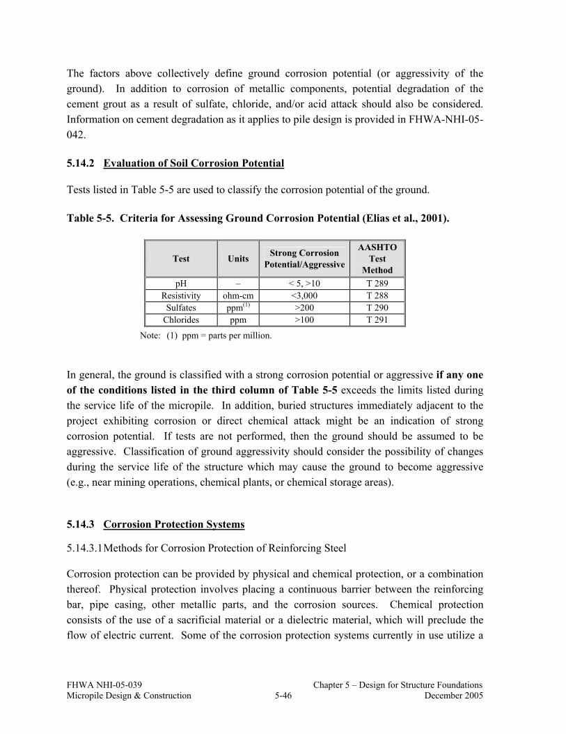
FHWA NHI-05-039 Chapter 5 – Design for Structure Foundations Micropile Design & Construction 5-46 December 2005
The factors above collectively define ground corrosion potential (or aggressivity of the ground). In addition to corrosion of metallic components, potential degradation of the cement grout as a result of sulfate, chloride, and/or acid attack should also be considered. Information on cement degradation as it applies to pile design is provided in FHWA-NHI-05-042.
5.14.2 Evaluation of Soil Corrosion Potential
Tests listed in Table 5-5 are used to classify the corrosion potential of the ground.
Table 5-5. Criteria for Assessing Ground Corrosion Potential (Elias et al., 2001).
Test Units Strong Corrosion Potential/Aggressive
AASHTO Test
Method pH – < 5, >10 T 289
Resistivity ohm-cm <3,000 T 288 Sulfates ppm(1) >200 T 290
Chlorides ppm >100 T 291
Note: (1) ppm = parts per million.
In general, the ground is classified with a strong corrosion potential or aggressive if any one of the conditions listed in the third column of Table 5-5 exceeds the limits listed during the service life of the micropile. In addition, buried structures immediately adjacent to the project exhibiting corrosion or direct chemical attack might be an indication of strong corrosion potential. If tests are not performed, then the ground should be assumed to be aggressive. Classification of ground aggressivity should consider the possibility of changes during the service life of the structure which may cause the ground to become aggressive (e.g., near mining operations, chemical plants, or chemical storage areas).
5.14.3 Corrosion Protection Systems
5.14.3.1 Methods for Corrosion Protection of Reinforcing Steel
Corrosion protection can be provided by physical and chemical protection, or a combination thereof. Physical protection involves placing a continuous barrier between the reinforcing bar, pipe casing, other metallic parts, and the corrosion sources. Chemical protection consists of the use of a sacrificial material or a dielectric material, which will preclude the flow of electric current. Some of the corrosion protection systems currently in use utilize a

FHWA NHI-05-039 Chapter 5 – Design for Structure Foundations Micropile Design & Construction 5-47 December 2005
combination of these mechanisms. The most common systems used to provide corrosion protection for micropiles are described below.
Grout Protection
This method of corrosion protection is used as a protective measure for the steel reinforcing bar and involves fully covering the reinforcing bar with neat cement grout. Centralizers are applied along the length of the bar (Figure 5-17(a)) to ensure adequate cover of grout between the bar and the side of the borehole. After the bar is centered in the drillhole, neat grout is injected and fills up the annular space around the steel bar. The grout provides an alkaline environment that reduces corrosion potential.
Epoxy Coating
Corrosion protection with epoxy consists of coating the reinforcing rod with a fusion-bonded epoxy that is applied by the manufacturer prior to shipment to the construction site. The minimum required thickness of epoxy coatings is typically 12 mils (0.3 mm). Thicker coatings may reduce steel to grout bond. The epoxy coating provides physical and chemical protection, as epoxy is a dielectric material. In transporting and handling bars, the epoxy coating may be damaged before bar installation. Therefore, it is not uncommon to spray epoxy coating in the field on chipped or nicked surfaces. Applicable standards for epoxy coating and allowable extent of damage (i.e., number of discontinuities in epoxy coating per unit length of bar) are found in ASTM A775/AASHTO M282. Patching materials should be approved by the epoxy coating manufacturer and should be inert in cement grout.
Galvanized Coating
A common method of providing corrosion protection is galvanization, which consists of applying a zinc coating on the steel surface. The process is performed by hot-dipping bars and other metallic pieces with zinc. The protection provided by galvanized coating is both physical and chemical, as this process forms a protective layer of zinc oxide. Galvanization shall meet the requirements of ASTM A153. Galvanization should not be used on high strength bars. Encapsulation
For maximum corrosion protection, a polyvinyl chloride (PVC) or high-density polyethylene (HDPE) (minimum 1-mm (0.04-in.) thick for PVC and 1.5-mm (0.06-in.) thick for HDPE) sheathing may be installed around the reinforcing bar similar to what is done for ground anchors in permanent applications. The sheathing is corrugated to transfer load to the surrounding grout. Grout-filled corrugated sheaths comprise double corrosion protection.

FHWA NHI-05-039 Chapter 5 – Design for Structure Foundations Micropile Design & Construction 5-48 December 2005
This system may be used with DSI threadbar and GEWI Bar (Figure 5-17(b)) and others. The encapsulation shall meet the requirements for encapsulation of soil and rock ground anchors as provided in PTI (2004).
5.14.3.2 Methods for Corrosion Protection of Steel Casing
Grout that may fill the annulus outside the steel casing is not considered to be sufficient to provide a quantifiable level of corrosion protection. Corrosion resistant coatings on permanent drill casing is impractical due to the abrasive action of the soil on the outer surface of the casing which would likely result in damage to the coating. Corrosion protection for steel casing subject to compressive loads in aggressive environments is typically considered by including a sacrificial steel thickness in the design. Casing should not be used to carry tension loads in aggressive ground environments.

FHWA NHI-05-039 Chapter 5 – Design for Structure Foundations Micropile Design & Construction 5-49 December 2005
TORQUEDANCHORPLATE
CONCRETESTRUCTURE
UPPER PILESTRENGTHENING
ELASTICSPACER
TORQUEDANCHORHEAD
ADDITIONALREINFORCEMENT(COMPRESSION)
ADDITIONALREINFORCEMENT
(TENSION)
CEMENTGROUT
(a)GEWI – PILE with
Standard Corrosion Protection
(b)GEWI – PILE with
Double Corrosion Protection
CORRUGATEDSHEATH
GEWI – BAROUTERCEMENTGROUT
INNERCEMENTGROUT
GEWI – BAR
Figure 5-17. GEWI Piles with (a) Grout Protection only; and (b) Double Corrosion Protection (Courtesy of DSI).

FHWA NHI-05-039 Chapter 5 – Design for Structure Foundations Micropile Design & Construction 5-50 December 2005
5.14.3.3 Corrosion Protection Requirements for Micropiles
Corrosion protection recommendations for micropiles are provided in Table 5-6.
Table 5-6. Corrosion Protection Recommendations for Micropiles (after DFI, 2004).
Corrosion Protection
Loading Tension1 Compression
Ground Aggressive2 Non aggressive Aggressive2 Non-aggressive
Casing a. Do not rely on casing for load capacity
a. None required if tension load on casing is less than 20% of casing thread strength
OR
b. Do not rely on casing for load capacity
a. Min.1.6 mm (0.063 in.) corrosion loss on outside
The Specifier may use different corrosion loss per site-specific corrosion studies.
a. None
The Specifier may use different corrosion loss per site-specific corrosion studies.
Core steel (reinforcing bar)l
a. epoxy coating3
OR
b. galvanization3
OR
c. encapsulation in plastic sheath3
AND
Grout cover4
a. bare steel5
OR
b. epoxy coating3
OR
c. galvanization3
OR
d. encapsulation in plastic sheath3
AND
Grout cover4
a. Grout cover4
AND
The Specifier may desire to add other options listed for tension.
a. Grout cover4
NOTES: 1. Permanent tension or temporary tension (e.g., wind, seismic, impact) on critical
structures. For temporary tension on normal structures, corrosion protection for compression may be used. The recommendations for corrosion protection for micropiles subject to tension loadings should also be used for that length of the micropile subject to tension as a result of lateral loads and/or overturning moments at the ground surface.
2. Corrosion protection must extend 5 m (15 ft) below corrosive material 3. Core steel corrosion protection must extend a minimum of 1.5 m (5 ft) into casing 4. Minimum 1 inch in soil and 0.5 inch in rock. If protective coatings (epoxy,
galvanization, or encapsulation) are provided in compression, minimum cover may be 0.25 inches in soil or rock.
5. Not recommended for permanent or cyclic tension loads.

FHWA NHI-05-039 Chapter 5 – Design for Structure Foundations Micropile Design & Construction 5-51 December 2005
Corrosion protection requirements (via sacrificial steel section losses) prescribed in Table 5-6 for casings subject to compressive loads in an aggressive ground environment include a minimum section loss of 1.6 mm (0.063 in.). This value is prescribed in AASHTO Section 4.5.7.4 for cross section reductions for concrete-filled pipe piles. Guidance on sacrificial thickness for structural steel elements in CCTG (1992) indicate that, for a design life of 75 years, a steel section loss range of 2 mm (0.0787 in.) to 5 mm (0.196 mm) is appropriate for non-protected steel in moderately to strongly corrosive environments, respectively, where no specific site corrosivity studies for the steel elements have been performed. Higher section losses are provided for a design life greater than 75 years.
These information sources provide a relatively wide range of corrosion losses. It is strongly recommended that site-specific corrosivity studies be performed where micropiles will be used in aggressive ground (as defined in Table 5-5).
5.15 PLUNGE LENGTH
The micropile detail shown in Figure 5-1 depicts a casing plunge length. With this detail (primarily used for micropiles with bond zones formed in soil), it is assumed that a portion of the micropile design load is transferred to the surrounding ground (over the plunge length) by the cased portion of the pile, thus reducing the load that must be supported by the uncased portion of the micropile (see Figure 5-18). This can allow a lesser amount of steel reinforcing through the uncased length to meet the structural strength requirements. The reduction in load applied to the uncased length is termed the transfer load, Ptransfer.
The allowable axial load transferred through the plunge length, Ptransfer-allowable may be calculated as:
)( LengthPlungeDFS
P bbond
allowabletransfer ×××=− πα
(Eq. 5-25)
The value for this load is based on the unit grout-to-ground bond, αbond (from Table 5-3) acting uniformly over the casing plunge length. It must be recognized that reliably achieving this load transfer depends on the casing installation method, the specific soil type and grouting method to obtain sufficient grout coverage between the casing and the surrounding ground.

FHWA NHI-05-039 Chapter 5 – Design for Structure Foundations Micropile Design & Construction 5-52 December 2005
For these reasons, micropile designs which incorporate a plunge length and a corresponding reduction in axial load reaching the uncased portion should be confirmed by the site-specific load testing information wherein axial load transfer over the plunge length is measured or can be computed based on verification load testing. Alternatively, Ptransfer may be conservatively neglected.
PILE BONDLENGTH
CASING PLUNGELENGTH
LOAD IN PILEPPILE (kN)
1
TRANSFER LOAD:PTRANSFER =
LOAD CARRIED BY PILE @ DEPTH 1 = PPILE
LOAD CARRIED BY PILE @ DEPTH 2 = PPILE – PTRANSFER
2
Db
αbond × 3.14 × Db × Casing Plunge Length
PILE BONDLENGTH
CASING PLUNGELENGTH
LOAD IN PILEPPILE (kN)
1
TRANSFER LOAD:PTRANSFER =
LOAD CARRIED BY PILE @ DEPTH 1 = PPILE
LOAD CARRIED BY PILE @ DEPTH 2 = PPILE – PTRANSFER
2
Db
αbond × 3.14 × Db × Casing Plunge Length
Figure 5-18. Detail of Load Transfer Through the Casing Plunge Length.
5.16 END BEARING MICROPILES
Due to the relatively small cross sectional area of micropiles, load carrying capacity resulting from end bearing is generally considered to be negligible for micropiles in soil or weak rock.

FHWA NHI-05-039 Chapter 5 – Design for Structure Foundations Micropile Design & Construction 5-53 December 2005
Micropiles founded on high quality sound rock, however, may develop their capacity primarily through end bearing and secondarily by side resistance. In this case, care must be taken to ensure that the micropile is not terminated on a boulder or on rock with voids or very soft material below. Where end bearing micropiles are being considered, the subsurface investigation should be sufficiently detailed to allow for a determination of the quality of the rock (see Table 5-2).
The design for end bearing micropiles may be done similar to end bearing drilled shafts, or may be based on previous load test experience of similar micropiles. Typically, a nominal length rock socket may be used (on the order of 0.6 m (2 ft)) to assure that the micropile is, in fact, founded on high quality rock. The capacity of end bearing micropiles on competent rock will likely be controlled by the structural capacity of the micropile since very high end bearing capacities can be achieved for micropiles on rock.
5.17 DOWNDRAG
Micropiles may be subjected to additional axial compression loading due to downdrag forces when the soils in contact with the cased portion of the micropile (i.e., above the bond zone) move downward relative to the micropile and tend to “drag” the micropile downward. The resulting downward force will add to the load applied to the micropile by the structure at the ground surface. The user of this manual is referred to the NHI/FHWA reference manuals for design of driven piles and for drilled shafts (FHWA-NHI-05-042 and FHWA-IF-99-025, respectively) for background information on downdrag and methods to compute downdrag forces.
The potential for downdrag exists when the surface soils can settle and where the foundation element passes through those settling soils into a stratum of relatively rigid geomaterial. Possible development of downdrag loads on micropiles should be considered where: (1) the site is underlain by compressible silts, clays, or peats; (2) fill has recently been placed on the earlier; and (3) the groundwater is substantially lowered.
If analyses or computations indicate that the surface soils are moving downward more than the micropile, a conservative solution can be obtained if it is assumed that the downdrag force will develop along the micropile from the ground surface to the top of the bond zone. To compute the downdrag force from the upper weak material, grout-to-ground bond stress values based on Table 5-3 should be used with consideration for the grouting technique used over the length of the micropile formed in the relatively weak materials. The maximum load along the micropile would occur at the top of the bond zone and would be the sum of the downdrag force and the load applied at the top of the micropile. The structural capacity of the micropile would be checked based on this total load.

FHWA NHI-05-039 Chapter 5 – Design for Structure Foundations Micropile Design & Construction 5-54 December 2005
The use of micropiles for a foundation system on sites where downdrag forces are of concern offers several benefits. The small surface area of a micropile will result in relatively small downdrag forces transmitted from the settling soil to the micropile. Further isolation of the micropile from the moving soils can be accomplished by installation of an additional oversized outer casing through the settling soils. Battered micropiles should not be used in soil conditions where large soil settlements are expected because of the additional bending forces imposed on the piles.
5.18 DESIGN OF MICROPILES FOR LATERAL LOADING
5.18.1 General
It is specifically noted that the analysis of a single vertical micropile for lateral loading and/or overturning moments is equivalent to that for a driven pile or drilled shaft. The user of this manual is referred to the NHI/FHWA reference manuals for design of driven piles and for drilled shafts (FHWA-NHI-05-042 and FHWA-IF-99-025, respectively) for specific modeling details related to lateral loading analysis. Herein, the overall design procedure for a laterally loaded micropile is provided (within the context of a p-y analysis) and specific issues that must be addressed for the design of a micropile subject to lateral load are discussed.
5.18.2 Analysis Steps for Single Laterally Loaded Micropile
Step 1: Determine basic pile input parameters for the micropile including: (1) pile length; (2) modulus of elasticity for grout, reinforcing bar, and steel casing; (3) distance from pile head to ground surface; and (4) slope of ground surface.
Step 2: Divide the micropile into segments with uniform cross sectional properties. For each segment, provide the pile diameter, moment of inertia, and area of pile.
A micropile subject to lateral loads and/or overturning moments will include a cased length in the upper portion of the micropile. A center steel reinforcing bar may be used along the entire length of the micropile, however the steel bar provides negligible resistance to lateral loads. Lateral loads and overturning moments applied at the ground surface will usually be carried by the portion of the micropile from the ground surface down to a depth on the order of 20 micropile diameters; below that depth bending moments will usually be negligible. The length of the micropile to be analyzed should be such that calculated bending moments, shear forces, and lateral pile movement are negligible at the bottom of the micropile. This length can be used to select the minimum micropile cased length.

FHWA NHI-05-039 Chapter 5 – Design for Structure Foundations Micropile Design & Construction 5-55 December 2005
Step 3: Delineate the soil/rock profile into layers over the maximum anticipated penetration depth of the trial micropile.
Step 4: Determine the required soil input parameters for each layer. For cohesive soil layers, the effective unit weight of the soil and the undrained shear strength is required for analysis while for cohesionless soils, the effective unit weight and drained friction angle is required.
The user inputs two additional parameters: (1) ε50 which is the axial strain corresponding to a shear stress equal to ½ of the shear strength of the material (this parameter is used for clays only); and (2) slope of the soil resistance versus lateral deflection curve, k. These values are typically selected based on soil type using Tables 5-7 through 5-10.
It is noted that user-defined p-y curves can be used for analysis where these curves are based on micropile lateral load test results (which include pile lateral movement measurements at the ground line and at various depths along the length of the micropile) from previous projects in similar ground or preproduction test piles. Actual foundation lateral displacements will likely be less than those measured in a load test since most load test setups do not incorporate the beneficial effects of pile cap stiffness and embedment below the ground surface which will likely be part of the actual foundation structure.
Most engineers, however, simply use the p-y curves contained within programs such as LPILE. These p-y curves have not been developed specifically for relatively small diameter micropiles but can provide reasonably accurate results. Moreover, good subsurface and shear strength characterization of the ground in the upper 5 m (15 ft) of the subsurface profile is critical to developing p-y curves for analysis (Richards and Rothbauer, 2004). If overly conservative assumptions regarding soil shear strength near the ground surface are used, it is likely that ground line lateral movements will be significantly overpredicted. Site specific strength data should be obtained.
Table 5-7. Values of ε50 for intact clays (after Reese et al., 2005).
Consistency of clay ε50
Soft 0.020 Medium 0.010
Stiff 0.005

FHWA NHI-05-039 Chapter 5 – Design for Structure Foundations Micropile Design & Construction 5-56 December 2005
Table 5-8. Values of ε50 for stiff clays (after Reese et al. 2005).
Undrained shear strength (kPa) (psi)
ε50
50 – 100 7.3 – 14.5 0.007 100 -200 14.5 – 29.0 0.005 300 -400 43.5 – 58.1 0.004
Table 5-9. Soil-modulus parameter (k) for sands (after Reese et al., 2005).
Loose Medium Dense Relative Density (kPa/m) (lb/in3) (kPa/m) (lb/in3) (kPa/m) (lb/in3)
Submerged Sand 5,430 20 16,300 60 33,900 125
Sand Above WT 6,790 25 24,430 90 61,000 225
Table 5-10. Soil-modulus parameter (k) for clays (after Reese et al., 2005).
Undrained Shear Strength Static Cyclic Clay
Consistency (kPa) (psi) (kPa/m) (lb/in3) (kPa/m ) (lb/in3)
Soft 12 – 24 1.74 – 3.47 8,140 30 - -
Medium 24 – 48 3.47 – 6.94 27,150 100 - -
Stiff 48 – 96 6.94 – 13.9 136,000 500 54,300 200
Very Stiff 96 – 192 13.9 – 27.8 271,000 1,000 108,500 400
Hard 192 - 383 27.8 – 55.6 543,000 2,000 217,000 800

FHWA NHI-05-039 Chapter 5 – Design for Structure Foundations Micropile Design & Construction 5-57 December 2005
Step 5: Determine the critical loading combinations and boundary conditions to be analyzed.
For each loading combination, determine the axial load, lateral load, and overturning moment at the ground line to be analyzed. An important input to the analysis is the assumed boundary condition at the ground line. In general, the assumption of full fixity at the pile head will result in large calculated negative bending moments at the top of the pile and small lateral deflections at the ground line. Conversely, the assumption of a pinned pile head connection will result in the largest calculated bending moment below the ground surface and relatively large calculated movements at the ground surface. The use of vertical micropiles to carry lateral loads is a relatively new application and little data exists to define the appropriate level of fixity for a given micropile-footing connection to be assumed for design analyses.
Typical practice is to evaluate the maximum bending moment from an analysis assuming pinned head conditions (i.e., 0% fixity) and the maximum bending moment from an analysis assuming fixed head conditions (i.e., 100% fixity). The structural capacity of the micropile is then checked for the larger of the two calculated bending moments.
Calculated ground line deflections are also affected by the assumed level of fixity for the micropile-footing connection. For assessing ground line deflections, a representative level of fixity should be assumed. In other words, the approach used to evaluate structural capacity is based on the “worst-case” bending moment from two analyses. This approach should not be used to assess deformations, but instead the level of fixity assumed to evaluate ground line deflections should be consistent with the actual micropile-footing connection. If a certain level of fixity is assumed in design, this level of fixity must be at least achieved by the actual (i.e., as-built) micropile-footing connection. To this end, Table 5-11 provides preliminary guidance for selecting a level of fixity for a given micropile-footing connection. The level of fixity (i.e., 0, 50, or 100 percent) can then be used in a lateral pile analysis to compute the lateral ground line deflection.
For a given micropile-footing connection, greater fixity than that reported in Table 5-11 may be able to be achieved. The user of this manual should assess fixity on a project-specific basis.

FHWA NHI-05-039 Chapter 5 – Design for Structure Foundations Micropile Design & Construction 5-58 December 2005
Table 5-11. Guidance on Level of Fixity for Micropile-Footing Connections.
0 % Fixity (Pinned Head Condition)
50 % Fixity(1) 100 % Fixity (Fixed Head Condition)(1)
Casing embedment of 300 mm (12 in.) or less or
Reinforcing bar embedment with or without bearing plate or
Any detail where top of micropile embedment is at or below the level of the bottom reinforcement of the footing
Casing embedment of 450 mm (18 in.) or
Shear connection between casing and existing footing with minimum casing embedment of 450 mm (18 in.)
Casing embedment of 600 mm (24 in.) or more
(1) Guidance provided assumes that footing itself is restrained. For example, if only one row of piles in direction of loading then 0% fixity should be assumed
Example LPILE analysis results are provided in Figure 5-19 and 5-20. The 50% fixity condition can be modeled in LPILE as follows:
• Perform LPILE analysis for case of 100% fixity (i.e., assume slope of zero for top of micropile) and compute negative bending moment at ground line, Mneg (100%);
• Perform second LPILE analysis with an assumed moment boundary condition equal to 50 percent of Mneg (100%); this analysis is used to obtain the ground line deflection.
Example LPILE analysis results and structural evaluation of the cased length using the combined stress (i.e., combined axial and bending) check (Eqs. 5-4 and 5-6) are provided in Sample Problem No. 2.

FHWA NHI-05-039 Chapter 5 – Design for Structure Foundations Micropile Design & Construction 5-59 December 2005
0
1
2
3
4
5
6
-40 -20 0 20 40 60Bending Moment (kN-m)
Dep
th (m
)
Fixed Head
50% Fixity
Free Head
Figure 5-19. LPILE Analysis Result for Bending Moment.
0
1
2
3
4
5
6
-5 0 5 10 15 20Deflection (mm)
Dep
th (m
)
Fixed Head
50% Fixity
Free Head
Figure 5-20. LPILE Analysis Result for Lateral Micropile Deflection.

FHWA NHI-05-039 Chapter 5 – Design for Structure Foundations Micropile Design & Construction 5-60 December 2005
Step 6: Determine structural capacity of the micropile for the critical case axial and lateral load.
The structural capacity of the micropile should be verified for combined stresses due to axial load and bending moment using Eq. 5-3 or Eq. 5-6. As previously mentioned, it may be conservatively assumed that the maximum bending moment is carried completely by the steel casing with no load being carried by the grout inside the casing. For this evaluation, it is assumed that the structural capacity of the micropile is not impacted by potential weaknesses at the threaded casing connection. The capacity of the connection and its effect on lateral load capacity is discussed in Section 5.5.3 and Section 5.18.3.
If the condition prescribed in Eq. 5-3 or Eq. 5-6 is not met, additional lateral loading capacity can be achieved by:
• installing an oversized casing in the top portion of the micropile where bending moments are high;
• constructing a larger micropile diameter at the top (which will tend to increase lateral soil resistance);
• embedding the pile cap deeper below the ground surface to develop more passive resistance which will result in reduced groundline deflections and bending moments (for a given lateral load); or
• battering some of the micropiles.
These options would need to be evaluated on a project-specific basis. For example, embedding the pile cap deeper may not be a viable option if the foundation layout has already been finalized for the project. That is, specific options may be outside the control of the micropile contractor.
Step 7: Determine pile acceptability based on deflection under the design load and modify the pile section properties, as needed, to meet lateral capacity and maximum groundline deflection criteria.
5.18.3 Evaluation of Micropile Lateral Load Capacity at Threaded Casing Joints
A conservative approach is provided herein to evaluate the bending moment capacity at a threaded casing joint. The method assumes that the wall thickness, tw, of the casing at the location of a threaded joint is equal to 50 percent of the intact casing wall thickness; therefore
FHWA NHI-05-039 Chapter 5 – Design for Structure Foundations Micropile Design & Construction 5-61 December 2005
the section modulus at the joint location is reduced. The outside diameter of the casing at the joint is then equal to OD – 2 (tw/2) = OD – tw. The reduced section modulus of the threaded joint, Sjoint is calculated as:
( )2/)(
)(64
2/)(
44
intint
w
w
w
jojo tOD
IDtOD
tODI
S−
−−×=
−=
π
(Eq. 5-26)
Eq. 5-3 is used to evaluate the maximum bending moment at a joint location, Mmax (joint), as follows:
be
a
a
ajojo F
Ff
Ff
SM
−×
−×= 'intint)(max 11 (Eq. 5-27)
The use of this method is demonstrated and discussed in Sample Problem No. 2.
5.19 LATERAL RESISTANCE OF MICROPILE GROUPS
5.19.1 General
Similar to other types of piles, micropile behavior in a group configuration is influenced by spacing between individual elements. The deflection of a pile group under a lateral load may be 2 to 3 times larger than the deflection of a single pile loaded to the same intensity. Holloway et al. (1981) and Brown et al. (1988) reported that piles in trailing rows of pile groups have significantly less resistance to a lateral load than piles in the lead row, and therefore exhibit greater deflections. This is due to the pile-soil-pile interaction that takes place in a pile group. The pile-soil-pile interaction results in the lateral capacity of a pile group being less than the sum of the lateral capacities of the individual piles comprising the group. Hence, laterally loaded pile groups have a group efficiency of less than 1. Based on experiments conducted as part of the FOREVER National Project (FOREVER, 2003) on horizontally loaded micropile groups, the following conclusions were drawn:
• For in-line micropiles, group effects are negligible for micropile spacing between 6 to 7 diameters; and
• For micropiles arranged in a row perpendicular to the direction of loading, group effects are negligible for micropile spacing just greater than 3 diameters.
FHWA NHI-05-039 Chapter 5 – Design for Structure Foundations Micropile Design & Construction 5-62 December 2005
The lateral capacity of an individual pile in a pile group is a function of its position in the group and the center to center pile spacing. Piles in trailing rows of pile groups have less resistance to a lateral load than pile sin the lead row, and therefore exhibit greater deflections. This is due to the pile-soil-pile interaction that takes place in a pile group. Brown et al. (1998) proposed a p-multiplier, Pm, be used to modify the p-y curve of an individual pile based upon the piles row position to account for this pile-soil-pile interaction. An illustration of the p-multiplier concept is presented in Figure 5-21. For piles in a given row, the same Pm value is applied to all p-y curves along the length of the pile. In a lateral load test of a 3 by 3 pile group in very dense sand with a center to center pile spacing of 3b, Brown found the leading row of piles had a Pm of 0.8 times that of an individual pile. The Pm values for the middle and back row of the group were 0.4 and 0.3, respectively.
A summary of additional laterally loaded driven pile group studies is provided in FHWA-NHI-05-042 (2005). Also, preliminary results from the FOREVER project indicate that Pm multipliers for micropiles may be slightly higher than those recommended herein, however, only limited data from centrifuge testing is available at this time.
Brown and Bollman (1993) proposed a p-multiplier procedure for the design of laterally loaded pile groups. This approach, outlined in the step by step procedure that follows, may be used for the design of laterally loaded micropile groups.
5.19.2 Step By Step Design Procedure For Laterally Loaded Pile Groups
Step 1: Develop p-y curves for single pile (see guidance for single pile previously provided)
Step 2: Perform LPILE analyses
a. Perform LPILE analyses using the Pm values for each row position to develop load-deflection and load-moment data.
b. Based on current data, it is suggested that Pm values of 0.8 be used for the
lead row, 0.4 for the second row, and 0.3 for the third and subsequent rows. These recommendations are considered reasonable for center to center pile spacing of three pile diameters and pile deflections at the ground surface ranging from 10 to 15 percent of the micropile diameter. For larger center to center spacings or smaller deflections (as would be anticipated for typical micropile groups), these Pm values should be conservative.

FHWA NHI-05-039 Chapter 5 – Design for Structure Foundations Micropile Design & Construction 5-63 December 2005
c. Determine shear load (at the ground line) versus deflection behavior for piles in each row. Plot load versus pile head deflection results similar to as shown in Figure 5-22(a). This plot can be developed for each row by selecting a set of shear loads and using LPILE to evaluate the deflection for each shear load.
Step 3: Estimate group deflection under lateral load
a. Average the load for a given deflection from all piles in the group to determine the average group response to a lateral load as shown in Figure 5-22(a).
b. Divide the lateral load to be resisted by the pile group by the number of
piles in the group to determine the average lateral load to be resisted by each pile. Enter load-deflection graph similar to Figure 5-22(a) with the average load per pile to estimate group deflection using the group average load deflection curve.
Step 4: Evaluate pile structural acceptability
a. Plot the maximum bending moment determined from LPILE analyses
versus deflection for each row of piles as illustrated in Figure 5-22(b). b. Use the estimated group deflection under the lateral load per pile to
determine the maximum bending moment for an individual pile in each row. Evaluate structural capacity according to Eq. 5-3 or Eq. 5-6 where the Mmax used in these equations is the maximum bending moment corresponding to the estimated group deflection.
Step 5: Perform refined pile group evaluation that considers superstructure-substructure interaction.
A detailed example demonstrating this procedure for a driven pile group can be found in Appendix F.8 of FHWA-NHI-05-042 (2005). The steps are the same as would be used for a micropile group.
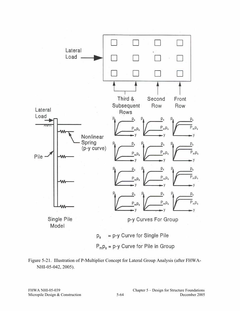
FHWA NHI-05-039 Chapter 5 – Design for Structure Foundations Micropile Design & Construction 5-64 December 2005
Figure 5-21. Illustration of P-Multiplier Concept for Lateral Group Analysis (after FHWA-NHI-05-042, 2005).

FHWA NHI-05-039 Chapter 5 – Design for Structure Foundations Micropile Design & Construction 5-65 December 2005
Figure 5-22. Load-Deflection and Bending Moment-Deflection for Pile Group Analysis
(after FHWA-NHI-05-042, 2005).

FHWA NHI-05-039 Chapter 5 – Design for Structure Foundations Micropile Design & Construction 5-66 December 2005
5.19.3 Soil-Structure Interaction Analyses for Micropile Groups
The methods described above uses analyses of single micropiles as a means to evaluate lateral load response of micropile groups. Micropiles are often used in combination with existing deep foundation elements. Because of this, estimates on the amount of load that will be shared by each individual foundation element need to be made. In some cases, this may be a statically indeterminate problem (i.e., loads need to be carried by, for example, more than 2 piles in a given cross section) requiring that the stiffness of the foundation elements (both existing and new micropiles) and the pile cap be considered in the analysis.
The computer program FB-Pier (2001) was developed with FHWA support as the primary design tool for analysis of pile groups under axial and lateral loads. This program is a nonlinear, finite element analysis, soil-structure interaction program. FB-Pier uses a p-multiplier approach in the evaluation of laterally loaded pile groups under axial, lateral, and combined axial and lateral loads. Additional information on FB-Pier program capabilities can be found at http://bsi-web.ce.ufl.edu. The computer program GROUP (2003) can also be used to model pile groups (see www.ensoftinc.com).
5.19.4 Battered Micropiles
The lateral load-carrying capacity of individual vertical micropiles is limited compared to more conventional drilled shafts and driven piles. As for other deep foundation systems, micropiles can be battered as a means to provide additional resistance to lateral loading. Note that since micropile drilling equipment is designed to drill both vertically and subvertically, there is not a significant increase in cost (on a per unit length basis) or quality of finished pile for battered micropiles as compared to vertical micropiles.
The calculation of lateral capacity of a single battered micropile is demonstrated in Sample Problem No. 1. The total lateral capacity of the battered micropiles is the sum of the lateral capacities of each battered micropile. This lateral capacity is compared to the lateral load applied to the foundation from the superstructure. If this sum is less than the lateral load applied to the foundation, the remaining load is carried by the micropiles in bending (i.e., this remaining load is used in a lateral load (i.e., LPILE analysis) for the structure).
Micropile groups with vertical and battered piles should be analyzed using the soil-structure interaction programs described in Section 5.19.3. Pile groups that contain battered piles are relatively stiff and will undergo less lateral movement for a given load than for a system with the same number of vertical piles. However, this increased system stiffness also results in greater bending moments in the pile cap which is a concern, especially for highly seismic

FHWA NHI-05-039 Chapter 5 – Design for Structure Foundations Micropile Design & Construction 5-67 December 2005
regions. Moreover, battered micropiles should not be used where the potential for ground settlement around the battered micropile is a possibility. These settlements will induce additional bending moments in the micropiles and some loss of support. Additional discussion on batter piles for seismic regions is discussed in Section 5.21.
5.20 BUCKLING CONSIDERATIONS FOR MICROPILES
5.21.1 General
Because micropiles are frequently installed to or into relatively sound rock or dense/hard soil, their capacity is frequently dictated by the structural strength of the element, rather than by the side resistance developed between the micropile grout and surrounding ground. The potential for buckling is reduced by the lateral restraint provided by the surrounding ground, however where soft or weak soils (e.g., very soft sedimentary deposits), voids (e.g., karstic formations), or liquefiable soils overly the bearing strata, buckling may potentially control the load-carrying capacity of a micropile and should be considered in design. For this reason, it is critical that the subsurface investigation identify these critical zones and, also, the depth of these zones should be recorded during the micropile installation process.
Herein, design analyses are presented to address micropile buckling. A more detailed coverage of micropile buckling is provided in Cadden and Gomez (2002).
5.21.2 Micropile Surrounded by Very Weak Or Liquefiable Soil
It is not possible to specifically define “very weak soil” or liquefiable soils by means of a readily available parameter such as SPT N value for purposes of evaluating buckling potential. Rather, a simple analysis is presented which uses a soil modulus parameter to evaluate whether buckling of the micropile is possible. The analysis involves comparing the critical buckling load for an axially loaded micropile, Pcr, to the maximum axial stress (i.e., capacity) of the micropile. For simplicity, only the contribution of the steel casing to resist buckling is considered, i.e., the potential benefits of grout within the casing and outside the casing are not considered as part of this analysis. Eq. 5-28 is used to estimate the critical buckling load:
2
2
2
2
ππ lE
lIEP s
cr += (Eq. 5-28)

FHWA NHI-05-039 Chapter 5 – Design for Structure Foundations Micropile Design & Construction 5-68 December 2005
where:
E = modulus of elasticity of the steel casing (e.g., 200,000 MPa (29,000 ksi));
I = moment of inertia of the micropile (previously defined for a steel casing in Eq. 5- 4);
l = “unsupported” length of the micropile assumed to be the thickness of the relatively weak or potentially liquefiable soil; and
Es = lateral reaction modulus of the soil surrounding the micropile over the “unsupported” length.
Using Eq. 5-28, the limiting lateral reaction soil modulus for buckling, EsLIMIT can be
evaluated as:
=
22
4
1
y
LIMITs
FE
AI
E (Eq. 5-29)
The first of the two terms inside the brackets in Eq. 5-29 represents the geometric properties of the pile, while the second term represents its material properties. The combination of these two terms is referred to as the pile factor and is given in units of [stress-1].
Using Eq. 5-29, if the EsLIMIT value is less than the measured or assumed soil modulus, Es,
then the geotechnical and structural strength of the micropile will control the micropile capacity and buckling does not need to be considered further. If the Es
LIMIT value is greater than Es, buckling should be evaluated further. Tables 5-12 and 5-13 provide ranges of Es values for various soil types.
Figure 5-23 provides a summary chart of limiting lateral reaction modulus values for various micropile materials.
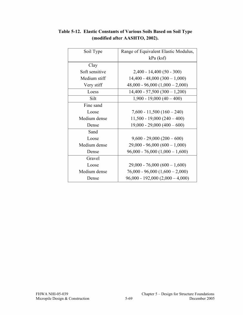
FHWA NHI-05-039 Chapter 5 – Design for Structure Foundations Micropile Design & Construction 5-69 December 2005
Table 5-12. Elastic Constants of Various Soils Based on Soil Type (modified after AASHTO, 2002).
Soil Type Range of Equivalent Elastic Modulus,
kPa (ksf) Clay
Soft sensitive Medium stiff
Very stiff
2,400 - 14,400 (50 - 300)
14,400 - 48,000 (300 – 1,000) 48,000 - 96,000 (1,000 – 2,000)
Loess 14,400 - 57,500 (300 – 1,200) Silt 1,900 - 19,000 (40 – 400)
Fine sand Loose
Medium dense Dense
7,600 - 11,500 (160 – 240) 11,500 - 19,000 (240 – 400) 19,000 - 29,000 (400 – 600)
Sand Loose
Medium dense Dense
9,600 - 29,000 (200 – 600)
29,000 - 96,000 (600 – 1,000) 96,000 - 76,000 (1,000 – 1,600)
Gravel Loose
Medium dense Dense
29,000 - 76,000 (600 – 1,600)
76,000 - 96,000 (1,600 – 2,000) 96,000 - 192,000 (2,000 – 4,000)

FHWA NHI-05-039 Chapter 5 – Design for Structure Foundations Micropile Design & Construction 5-70 December 2005
Table 5-13. Elastic Constants of Various Soils Based on SPT N Value (modified after AASHTO, 2002).
Soil Type Equivalent Elastic Modulus,
kPa (ksf) Silts, sandy silts, slightly
cohesive mixtures 400 (N1)60 (8 (N1)60)
Clean fine to medium sands and slightly silty sands
700 (N1)60 (14 (N1)60)
Coarse sands and sands with little gravel
1,000 (N1)60 (20 (N1)60)
Sandy gravels 1,200 (N1)60 (24 (N1)60)
97 105
159
71
27 23 19 17
610
610
610
610
610
610
295
253
310 34
3
165
350
0
100
200
300
400
500
600
700
5.5"
x0.3
6" 8
0 ks
i cas
ing
7"x0
.5"
80 k
si c
asin
g
7"x0
.73"
80
ksi c
asin
g
9.62
5"x0
.47"
80
ksi c
asin
g
5 ½
-inc
h ca
sing
6 ⅝
–inc
h ca
sing
8-in
ch c
asin
g
10 ¾
-inc
h ca
sing
#10
Bar
#11
Bar
#14
Bar
#18
Bar
#20
Bar
#28
Bar
30/1
6
32/2
0
40/2
0
52/2
6
73/5
3
103/
51
Lim
iting
Es
(psi
)
Figure 5-23. Limiting Lateral Modulus Values for Various Micropile Materials (after Cadden and Gomez, 2002).

FHWA NHI-05-039 Chapter 5 – Design for Structure Foundations Micropile Design & Construction 5-71 December 2005
If the analysis presented above indicates the potential for buckling (i.e., EsLIMIT > Es), the
allowable compression load for the cased section subject to buckling should be calculated. Eq. 5-1 can be modified to account for buckling as:
( )[ ]steely
agcabarsteelygroutgroutcallowablec F
FAAFAfP−
−−− ×++×=47.0
47.04.0 sin' (Eq. 5-30)
In Eq. 5-30, the allowable stress, Fa is calculated based on the following:
−×=≤< −2
2
21,0
c
tsteelyac
t CrKl
FSF
FCrKlif (Eq. 5-31)
[ ]2
2
,t
steelac
t rKlFSE
FCrKlif
π=> (Eq. 5-32)
where steely
steelc F
EC
−
=22π
K = effective length factor (assumed equal to 1.0 and previously defined in Section 5.6);
l = unsupported length of the micropile; rt = radius of gyration of the steel section only = (I/A)1/2; FS = factor of safety = 2.12 (see Table 10.32.1.A in AASHTO (2002)) and Fy-steel = the casing yield stress.
For this analysis, the unsupported length of the micropile, l, is assumed to be the thickness of the weak soil surrounding the micropile and the effective length factor is conservatively assumed to be 1.0. Also, this analysis can be used to consider scour in which the depth of scour is assumed to be the unsupported length of the micropile.
Where combined axial and bending stresses are present and where buckling should be checked (based on the evaluations presented in this section), Eq. 5-3 should be used.

FHWA NHI-05-039 Chapter 5 – Design for Structure Foundations Micropile Design & Construction 5-72 December 2005
5.20.3 Micropiles Installed through Voids
Figure 5-24 illustrates the case of a micropile installed through a void such as for a micropile installed in karst terrain. The micropile is subject to a centered load P applied at the top, and penetrates consistent ground throughout its entire length, except at the void location.
The structural capacity of such a micropile should be checked using Eq. 5-30. Depending on the procedure followed for micropile installation, the portion of the pile through the void may be analyzed as a doubly pinned, pinned-fixed, or fixed-fixed column and k selected accordingly. The model in Figure 5-24 assumes that the pile has been grouted only along the bond length, and that an annular gap around the casing exists throughout its unbonded length. Under these conditions, the micropile can be conservatively assumed to be pinned on both ends such that k = 1.0.
Figure 5-24. Micropile Installed Through Voids in Karstic Terrain; (a) Actual Configuration, (b) Model Used for Estimation of Structural Capacity (after Cadden and Gomez, 2002).
P
M
P
(a) (b)
voi

FHWA NHI-05-039 Chapter 5 – Design for Structure Foundations Micropile Design & Construction 5-73 December 2005
In cases where the pile extends through hard rock above the void, consideration should be given to the effect this may have on the ability of lateral loads or moments to transfer to the portion of the pile within the void. If the pile is fixed in a rock layer above a void, then there will not be any lateral load that is transferred to portion of micropile over the length of the void; only vertical load is transferred over that length. The calculated allowable load assuming lateral load is transferred over the length of the void is therefore conservative for this case.
Micropiles may be susceptible to buckling-induced failure at the casing joints. To consider the effect of joints, Eq. 5-29 is used to evaluate the critical or limiting lateral soil reaction using a reduced value for the moment of inertia. This value for I is calculated as for Ijoint in Eq. 5-26. It is noted that this method is conservative since it assumes that the micropile stiffness is equivalent to that of the joint over the entire length of the unsupported micropile. More detailed structural analyses could be carried out that only use the reduced casing stiffness over the length of the joint, however, these are relatively complex and beyond the scope of this report. As a practical consideration, however, micropiles installed through karst must be designed for buckling, considering the presence of the casing joints, or should include installation of continuous internal reinforcement along portions of micropile traversing voids or very soft or loose soil.
5.21 SEISMIC CONSIDERATIONS
5.21.1 General
Micropiles have been used for seismic retrofit projects in which existing deep foundations have been shown to have insufficient capacity to resist seismic forces consistent with the design earthquake. As discussed in Chapter 3, seismic retrofit projects typically involve adding micropiles to an existing foundation to provide additional capacity required to withstand seismic effects (i.e., overturning, uplift, lateral forces). Current guidance for seismic design of bridge foundations is provided in Division I-A of AASHTO (2002) and the recommendations provided here apply generally to micropiles subject to seismic effects. Additional information on seismic design of micropiles is found in JPWRI (2002)
As shown in Figure 5-25, the seismic response of a pile foundation involves the distribution of a set of superstructure loads into the surrounding soil mass through the pile members. The general case involves consideration of three components of translational forces (an axial and two lateral shear forces) and three components of rotational moments (a torsional moment about the pile axis and two rotational moments about two orthogonal horizontal axes) along the pile member.

FHWA NHI-05-039 Chapter 5 – Design for Structure Foundations Micropile Design & Construction 5-74 December 2005
Figure 5-25. Three-dimensional Soil Pile Interaction (after Bryant and Matlock, 1977).
The evaluation of the dynamic response of a pile foundation can be performed using either a pseudo-static analysis or a dynamic response analysis. A realistic approach to dynamic analysis of pile foundations should account for the nonlinear behavior of near-surface soils and the layered nature of typical soil profiles. In view of these constraints, current design practice usually models the soil support characteristics along the pile by discrete nonlinear springs. The pile is modeled as a beam-column supported by one set of lateral springs (using p-y curves as previously discussed) and another set of axial springs. The curves for the axial load transfer characteristics of the pile are referred to as t-z curves. Torsional resistance against rotation of individual piles is usually ignored or assumed to be negligible for highway bridges, as most deep highway foundations are supported by pile groups and torsional loads on pile groups become resolved as lateral loads on the individual piles.
For evaluating the vertical response of piles subject to dynamic loading, t-z curves are generally calculated over the entire length of the pile. Procedures for evaluating t-z curves are provided by Lam and Martin (1986, 1997) and Kraft et al. (1981a, b).

FHWA NHI-05-039 Chapter 5 – Design for Structure Foundations Micropile Design & Construction 5-75 December 2005
5.21.2 Use of Battered Micropiles in Highly Seismic Regions
Vertical micropiles in groups do little to resist horizontal seismic deformations due to their relatively low stiffness (FOREVER, 2003). Under seismic loading, however, battered micropiles will have a reduced positive bending moment (as compared to vertical micropiles), but significantly higher negative bending moments at the pile head. In current U.S. practice, the concern over excessive bending moments being mobilized during the design seismic event has resulted in some owner agencies disallowing the use of battered piles for seismic retrofit projects.
Trinh et al. (2004) performed finite element analyses to investigate the effects of combined axial compression and lateral displacements on battered micropiles. The micropile foundation consisted of a square column supported on a 4572 mm by 4572 mm (180 in. by 180 in.) 915-mm (36-in.) high pile cap. Twelve, 178-mm (7-in.) diameter micropiles arranged in the configuration shown in Figure 5-26 were used to support the pile cap. Micropiles were battered inward at 15 degrees and outward at 25 degrees from the vertical.
2
3 4
5
6
78
910
11
12X
Y1
60" Square Column
180" Square Pile Cap
V 0
2
3 4
5
6
7
8
9
10
11
12X
Y1OUT
IN
IN
IN
IN
IN
IN
OUT
OUT
OUT
OUT
OUT
Column
Pile Cap
0
(a) Pile spacing (b) Pile inclination
Figure 5-26. Plan View of the Micropile Foundation (after Trinh et al., 2004).
They concluded that with an adequate amount of flexural reinforcement in the pile cap, the failure mode of the micropile foundation will primarily involve yielding of the micropiles or pullout of the micropile itself with little (if any) yielding of the micropile-footing connection. Figure 5-27 shows the effect of increasing steel reinforcement in the cap. This figure indicates that a fully ductile response of the foundation can be achieved with a flexural

FHWA NHI-05-039 Chapter 5 – Design for Structure Foundations Micropile Design & Construction 5-76 December 2005
reinforcement ratio, ρs (equal to area of flexural steel reinforcement to cross section area) of about 0.5 percent. Ductility implies that the foundation does not undergo significant loss of lateral support at large lateral displacements and/or where the ratio of ultimate deformation to deformation at yield is relatively large. If the micropile-footing connection were to incur higher than expected loading, the connection is expected to perform in a highly ductile manner and the potential failure mechanism would be either pullout of the micropile or yielding of the micropile.
5.21.3 Load Sharing with Existing Foundations
Applications in which micropiles are used to seismically retrofit an existing deep foundation requires that load sharing between existing foundation elements and the micropiles be evaluated. Where additional foundation elements are required to support additional compression and uplift forces (e.g., rocking motions), vertical micropiles are used.
Figure 5-27. Lateral Response of Micropile Foundation for Different Flexural Reinforcement Ratio (after Trinh et al., 2004).

FHWA NHI-05-039 Chapter 5 – Design for Structure Foundations Micropile Design & Construction 5-77 December 2005
For the retrofit design of an old or deteriorated foundation or for a foundation in which the original structural design details and specifications are uncertain, design seismic loads should be assumed to be carried by the micropiles only. Load sharing between existing and new foundations should only be considered if sufficient information on the existing foundation system (i.e., as-built drawings, load test results, design calculations) is available. Where this is considered, soil-structure interaction analyses will need to be performed.
5.21.4 Pile Uplift Capacity
Individual piles in pile groups will be subjected to significant uplift resulting from seismic loading. The overturning moment applied by the seismic lateral force to the pile cap is typically resisted by axial resistance in the piles with the outermost piles in the group being subjected to relatively large cyclic axial loads.
Section 6.4.2(B) of AASHTO (2002) Division I-A suggests that some separation between the bottom of the pile cap and the foundation soil is allowed, provided that the foundation soil is not susceptible to loss of strength (e.g., liquefaction) under the imposed cyclic loading. For pile groups, up to one-half the bearing area of the pile cap is allowed. In Section 6.4.2(C), AASHTO recommends that the ultimate capacity of the piles be used in designing the foundation for uplift forces resulting from seismic forces (i.e., FS = 1.0 on geotechnical uplift capacity). It is noted that all other permanent loads are included in this assessment. Structural requirements including embedment length of the pile in the pile cap and the detailing of the connections need to be considered, as discussed below.
As part of the Trinh et al (2004) study, battered micropiles on the outboard side of the pile cap were shown to develop large tensile forces and relatively severe cracking even though the foundation was subject to large vertical compression forces. They concluded that a prudent design approach would include increasing the amount of vertical shear reinforcement (i.e., placing steel reinforcement at closer spacing) in the cap near the piles that are furthest from the column (i.e., the outboard piles) to mitigate cracking of the cap concrete.
5.21.5 Liquefaction
In many earthquakes where liquefaction occurs, the soil may not liquefy until the end of the earthquake. Therefore, piles in liquefied ground may still be able to rely on the vertical and lateral support of the soil in the potentially liquefied zone during the earthquake. However, due to uncertainties as to exactly when liquefaction will occur, it is common practice to assign a reduced vertical and lateral resistance to potentially liquefiable soil surrounding a pile if the pile is expected to function as a load carrying member during and after an earthquake. Results presented by Ishihara and Cubrinovski (1998) suggest that the lateral
FHWA NHI-05-039 Chapter 5 – Design for Structure Foundations Micropile Design & Construction 5-78 December 2005
resistance of a pile in liquefied ground is approximately 0.1 to 1.0 percent of the lateral resistance in non-liquefied ground. Therefore, if a pile foundation in potentially liquefiable soil is expected to carry lateral loads after the surrounding soil liquefies, batter piles may be required to provide adequate lateral support. This reduction in lateral support is particularly important for relatively flexible micropiles.
Studies reported in the FOREVER (2003) project showed that vertical micropiles were not effective in reducing liquefaction. Batter micropiles, however, were shown to limit seismically-induced soil movements (and pore pressure buildup) resulting in no liquefaction in the zone affected by the piles, whereas the free-field soil did undergo liquefaction. If batter piles are used, the pile cap connections should be designed to sustain moment loads induced by lateral movements and the batter piles should be designed to sustain lateral loads due to soil settlement.

FHWA NHI-05-039 Chapter 5 – Design for Structure Foundations Micropile Design & Construction 5-79 December 2005
5.22 REFERENCES
AASHTO (1988), “Manual on Subsurface Investigations”, American Association of State Highway and Transportation Officials Publication, Washington, D.C.
AASHTO (2002), “Standard Specifications for Highway Bridges”, Association of State Highway and Transportation Officials Publication, Washington, D.C. ISBN: 156051-171-0.
Brown, D. A., Morrison, C., and Reese, L. C. (1988), “Lateral Load Behavior of Pile Group in Sand”, ASCE Journal of Geotechnical Engineering, Vol. 114, No. 11, pp. 1261-1276.
Brown, D. A. and Bollman, H. T. (1993), “Pile-Supported Bridge Foundations Designed For Impact Loading”, Appended Document to the Proceedings of Design of Highway Bridges for Extreme Events, Crystal City, Virginia, pp. 265-281.
Bruce, D. A. and Gemme, R., (1992) “Current Practice in Structural Underpinning Using Pinpiles,” Proceedings, New York Met Section, ASCE Seminar, New York, April 21-22, 46 pages.
Bryant, L.M. and Matlock, H. (1977), "Three Dimensional Analysis of Framed Structures with Nonlinear Pile Foundations," Proc. 9th Annual Offshore Technology Conference, Houston, Texas, Paper No. 2955.
Cadden, A. and Gomez, J. (2002), “Buckling of Micropiles – A Review of Historic Research and Recent Experiences”, Schnabel Engineering Associates Report, West Chester, PA.
Cheney, R. S. (1988), “Permanent Ground Anchors”, Federal Highway Administration Report, Report No. FHWA-DP-68-1R, Washington, D.C.
CCTG (1992). “Technical Rules for the Design and Calculation of the Foundations of Civil Engineering Works,” Publication 62, Title V.
DFI (2004), “Guide to Drafting a Specification for Micropiles”, Deep Foundations Institute, The International Association of Foundation Drilling, 60 pages, New Jersey.
Elias, V., Christopher, B.R., and Berg, R.R. (2001), “Mechanically Stabilized Earth Walls and Reinforced Soil Slopes: Design and Construction Guidelines”, Federal Highway Administration, Report No. FHWA-NHI-00-043, Washington, D.C.

FHWA NHI-05-039 Chapter 5 – Design for Structure Foundations Micropile Design & Construction 5-80 December 2005
Eurocode EC8 (1994), “Structures in Seismic Regions, Part 5, Foundations, Retaining Structures, and Geotechnical Aspects.”
FB-PIER (2001), “A Program for the Geotechnical and Structural Aspects of Foundation and Pier Design”, Federal Highway Administration and University of Florida, Bridge Software Institute (BSI), Manual No. of the Program FHWA-IF-01-010, Distribution of software at http://bsi-web.ce.ufl.edu.
FHWA/NHI (2001), “Manual on Subsurface Investigations”, Federal Highway Administration, Manual No. FHWA NHI-01-031, Mayne, P. W., Christopher, B. R., and DeJong, J., July.
Federal Highway Administration (2005), “Design and Construction of Driven Pile Foundations”, Hannigan, P. J., Goble, G. G., Thendean, G., Likins, G. E., and Rausche, F., Publication No. FHWA-NHI-05-042, United States Department of Transportation, December.
Federal Highway Administration (1997), “Drilled and Grouted Micropiles, State-of-Practice Review”, Bruce, D. A. and Juran, I., Report No. FHWA-RD-96-016/019, United States Department of Transportation, July, Four Volumes.
Federal Highway Administration (1999), “Drilled Shafts: Construction Procedures and Design Methods”, O’Neil, M. W. and Reese, L. C., Publication No. FHWA-HI-99-025, United States Department of Transportation, August.
FOREVER (2003), “Synthesis of the Results of the National Project on Micropiles”, International Center for Ground Improvement, Polytechnic University, Juran, I, Jahir Hasan, Weinstein, G. M, and Sourisseau, L.
GROUP (2003), “A Program for the Analysis of Piles in a Group”, Ensoft Engineering Software, Distribution of software http://www.ensoftinc.com/.
GEC No. 4 (1999), “Ground Anchors and Anchored Systems”, Geotechnical Engineering Circular 4, Federal Highway Administration Publication, Sabatini, P. J., Pass, D. G., and Bachus, R. C., Publication Number: FHWA-IF-99-015.
GEC No. 5 (2002), “Evaluation of Soil and Rock Properties”, Geotechnical Engineering Circular 5, Federal Highway Administration Publication, Sabatini, P. J., Bachus, R. C., Mayne, P. W., Schneider, J. A., and Zettler, T. E., Publication Number: FHWA-IF-02-034.

FHWA NHI-05-039 Chapter 5 – Design for Structure Foundations Micropile Design & Construction 5-81 December 2005
Holloway, D. M., Moriwaki, Y. Stevens, J. B., and Perez, J-Y. (1981), “Response of a Pile Group to Combined Axial and Lateral Loading”, Proceedings of the 10th International Conference on Soil Mechanics and Foundation Engineering, Boulimia Publishers, Stockholm, Vol. 2, pp. 731-734.
Hough, B.K. (1959), “Compressibility as the Basis for Soil Bearing Value,” ASCE Journal of Soil Mechanics and Foundation Engineering, Vol. 85, No. SM4, pp. 11-39.
Ishihara, K. and Cubrinovski, M. (1998), “Soil-Pile Interaction in Liquefied Deposits undergoing Lateral Spreading,” Proc. 11th Danube-European Conference on Soil Mechanics and Geotechnical Engineering, Porec, Croatia, pp. 51-64.
Japanese Public Works Research Institute (JPWRI) (2002), “Design and Execution Manual for Seismic Retrofitting of Existing Pile Foundations with High Capacity Micropiles”, Foundation Engineering Research Team, Structures Research Group.
Kraft, L.M., Jr, Focht, J., Jr. and Amerasinghe, S.F. (1981a), “Friction Capacity of Piles Driven into Clay,” Journal of Geotechnical Engineering Division, ASCE, Vol. 107, No. GT11, pp. 1521-1541.
Kraft, L.M., Jr, Ray, R. and Kagawa, T. (1981b), “Theoretical t-z Curves,” Journal of Geotechnical Engineering Division, ASCE, Vol. 107, No. GT11, pp. 1543-1561.
Lam, I.P. and Martin, G.R. (1986), "Seismic Design of Highway Bridge Foundations - Vol. II. Design Procedures and Guidelines," Report No. FHWA/RD-86-102, U.S. Department of Transportation, Federal Highway Administration, McLean, Virginia, 167 p.
Lam, I.P. and Martin, G.R. (1997), "Current Developments in Seismic Design of Bridge Foundations," Proc. Transportation Research Board 76th Annual Meeting, Session No. 236, Washington, District of Columbia, 21 p.
Meyerhoff, G.G. (1976), “Bearing Capacity and Settlement of Piled Foundations”, Proceedings of the American Society of Civil Engineers, GT#3, pp. 197-228.
Ostermayer, H. (1975), “Construction, Carrying Behavior, and Creep Characteristics of Ground Anchors”, Conference on Diaphragm Walls and Anchorages, Institute of Civil Engineers, London.
PTI (2004) “Recommendations for Prestressed Rock and Soil Anchors”, Post-Tensioning Institute Publication.

FHWA NHI-05-039 Chapter 5 – Design for Structure Foundations Micropile Design & Construction 5-82 December 2005
Reese, L. C., Wang, S. T., Isenhower, W. M., Arréllaga, J. A., and Hendrix, J., (2005), “A Program for Analysis of Single Piles Under lateral Load”, Version 5.0.18, Ensoft Inc., Austin, TX.
Richards, T.D. and Rothbauer, M.J. (2004), “Lateral Loads on Pin Piles (Micropiles),” Geotechnical Special Publication “Drilled Shafts, Micropiling, Deep Mixing, Remedial Methods, and Specialty Foundation Systems”, ASCE Publication, No.: 124, pp.158-174.
Trinh, R.S., Jain, V., Kunnath, S.K., and Chai, Y.H. (2004), “Finite Element Modeling of Inclined Micropile Foundation under Combined Axial Compression and Lateral Displacement”, Final Summary Report submitted to SALUT.
Weatherby, D. E. (1982), “Tiebacks”, Federal Highway Administration Report, Report No. FHWA/RD-82/047, McLean, VA.
Xanthakos, P.P., Abramson, L. W., and Bruce, D.A., (1994) “Ground Control and Improvement”, John Wiley & Sons, Inc., New York, NY.

FHWA NHI-05-039 Chapter 5 – Design for Structure Foundations Micropile Design & Construction 5-79 December 2005
5.22 REFERENCES
AASHTO (1988), “Manual on Subsurface Investigations”, American Association of State Highway and Transportation Officials Publication, Washington, D.C.
AASHTO (2002), “Standard Specifications for Highway Bridges”, Association of State Highway and Transportation Officials Publication, Washington, D.C. ISBN: 156051-171-0.
Brown, D. A., Morrison, C., and Reese, L. C. (1988), “Lateral Load Behavior of Pile Group in Sand”, ASCE Journal of Geotechnical Engineering, Vol. 114, No. 11, pp. 1261-1276.
Brown, D. A. and Bollman, H. T. (1993), “Pile-Supported Bridge Foundations Designed For Impact Loading”, Appended Document to the Proceedings of Design of Highway Bridges for Extreme Events, Crystal City, Virginia, pp. 265-281.
Bruce, D. A. and Gemme, R., (1992) “Current Practice in Structural Underpinning Using Pinpiles,” Proceedings, New York Met Section, ASCE Seminar, New York, April 21-22, 46 pages.
Bryant, L.M. and Matlock, H. (1977), "Three Dimensional Analysis of Framed Structures with Nonlinear Pile Foundations," Proc. 9th Annual Offshore Technology Conference, Houston, Texas, Paper No. 2955.
Cadden, A. and Gomez, J. (2002), “Buckling of Micropiles – A Review of Historic Research and Recent Experiences”, Schnabel Engineering Associates Report, West Chester, PA.
Cheney, R. S. (1988), “Permanent Ground Anchors”, Federal Highway Administration Report, Report No. FHWA-DP-68-1R, Washington, D.C.
CCTG (1992). “Technical Rules for the Design and Calculation of the Foundations of Civil Engineering Works,” Publication 62, Title V.
DFI (2004), “Guide to Drafting a Specification for Micropiles”, Deep Foundations Institute, The International Association of Foundation Drilling, 60 pages, New Jersey.
Elias, V., Christopher, B.R., and Berg, R.R. (2001), “Mechanically Stabilized Earth Walls and Reinforced Soil Slopes: Design and Construction Guidelines”, Federal Highway Administration, Report No. FHWA-NHI-00-043, Washington, D.C.
FHWA NHI-05-039 Chapter 5 – Design for Structure Foundations Micropile Design & Construction 5-80 December 2005
Eurocode EC8 (1994), “Structures in Seismic Regions, Part 5, Foundations, Retaining Structures, and Geotechnical Aspects.”
FB-PIER (2001), “A Program for the Geotechnical and Structural Aspects of Foundation and Pier Design”, Federal Highway Administration and University of Florida, Bridge Software Institute (BSI), Manual No. of the Program FHWA-IF-01-010, Distribution of software at http://bsi-web.ce.ufl.edu.
FHWA/NHI (2001), “Manual on Subsurface Investigations”, Federal Highway Administration, Manual No. FHWA NHI-01-031, Mayne, P. W., Christopher, B. R., and DeJong, J., July.
Federal Highway Administration (2005), “Design and Construction of Driven Pile Foundations”, Hannigan, P. J., Goble, G. G., Thendean, G., Likins, G. E., and Rausche, F., Publication No. FHWA-NHI-05-042, United States Department of Transportation, December.
Federal Highway Administration (1997), “Drilled and Grouted Micropiles, State-of-Practice Review”, Bruce, D. A. and Juran, I., Report No. FHWA-RD-96-016/019, United States Department of Transportation, July, Four Volumes.
Federal Highway Administration (1999), “Drilled Shafts: Construction Procedures and Design Methods”, O’Neil, M. W. and Reese, L. C., Publication No. FHWA-HI-99-025, United States Department of Transportation, August.
FOREVER (2003), “Synthesis of the Results of the National Project on Micropiles”, International Center for Ground Improvement, Polytechnic University, Juran, I, Jahir Hasan, Weinstein, G. M, and Sourisseau, L.
GROUP (2003), “A Program for the Analysis of Piles in a Group”, Ensoft Engineering Software, Distribution of software http://www.ensoftinc.com/.
GEC No. 4 (1999), “Ground Anchors and Anchored Systems”, Geotechnical Engineering Circular 4, Federal Highway Administration Publication, Sabatini, P. J., Pass, D. G., and Bachus, R. C., Publication Number: FHWA-IF-99-015.
GEC No. 5 (2002), “Evaluation of Soil and Rock Properties”, Geotechnical Engineering Circular 5, Federal Highway Administration Publication, Sabatini, P. J., Bachus, R. C., Mayne, P. W., Schneider, J. A., and Zettler, T. E., Publication Number: FHWA-IF-02-034.

FHWA NHI-05-039 Chapter 5 – Design for Structure Foundations Micropile Design & Construction 5-81 December 2005
Holloway, D. M., Moriwaki, Y. Stevens, J. B., and Perez, J-Y. (1981), “Response of a Pile Group to Combined Axial and Lateral Loading”, Proceedings of the 10th International Conference on Soil Mechanics and Foundation Engineering, Boulimia Publishers, Stockholm, Vol. 2, pp. 731-734.
Hough, B.K. (1959), “Compressibility as the Basis for Soil Bearing Value,” ASCE Journal of Soil Mechanics and Foundation Engineering, Vol. 85, No. SM4, pp. 11-39.
Ishihara, K. and Cubrinovski, M. (1998), “Soil-Pile Interaction in Liquefied Deposits undergoing Lateral Spreading,” Proc. 11th Danube-European Conference on Soil Mechanics and Geotechnical Engineering, Porec, Croatia, pp. 51-64.
Japanese Public Works Research Institute (JPWRI) (2002), “Design and Execution Manual for Seismic Retrofitting of Existing Pile Foundations with High Capacity Micropiles”, Foundation Engineering Research Team, Structures Research Group.
Kraft, L.M., Jr, Focht, J., Jr. and Amerasinghe, S.F. (1981a), “Friction Capacity of Piles Driven into Clay,” Journal of Geotechnical Engineering Division, ASCE, Vol. 107, No. GT11, pp. 1521-1541.
Kraft, L.M., Jr, Ray, R. and Kagawa, T. (1981b), “Theoretical t-z Curves,” Journal of Geotechnical Engineering Division, ASCE, Vol. 107, No. GT11, pp. 1543-1561.
Lam, I.P. and Martin, G.R. (1986), "Seismic Design of Highway Bridge Foundations - Vol. II. Design Procedures and Guidelines," Report No. FHWA/RD-86-102, U.S. Department of Transportation, Federal Highway Administration, McLean, Virginia, 167 p.
Lam, I.P. and Martin, G.R. (1997), "Current Developments in Seismic Design of Bridge Foundations," Proc. Transportation Research Board 76th Annual Meeting, Session No. 236, Washington, District of Columbia, 21 p.
Meyerhoff, G.G. (1976), “Bearing Capacity and Settlement of Piled Foundations”, Proceedings of the American Society of Civil Engineers, GT#3, pp. 197-228.
Ostermayer, H. (1975), “Construction, Carrying Behavior, and Creep Characteristics of Ground Anchors”, Conference on Diaphragm Walls and Anchorages, Institute of Civil Engineers, London.
PTI (2004) “Recommendations for Prestressed Rock and Soil Anchors”, Post-Tensioning Institute Publication.

FHWA NHI-05-039 Chapter 5 – Design for Structure Foundations Micropile Design & Construction 5-82 December 2005
Reese, L. C., Wang, S. T., Isenhower, W. M., Arréllaga, J. A., and Hendrix, J., (2005), “A Program for Analysis of Single Piles Under lateral Load”, Version 5.0.18, Ensoft Inc., Austin, TX.
Richards, T.D. and Rothbauer, M.J. (2004), “Lateral Loads on Pin Piles (Micropiles),” Geotechnical Special Publication “Drilled Shafts, Micropiling, Deep Mixing, Remedial Methods, and Specialty Foundation Systems”, ASCE Publication, No.: 124, pp.158-174.
Trinh, R.S., Jain, V., Kunnath, S.K., and Chai, Y.H. (2004), “Finite Element Modeling of Inclined Micropile Foundation under Combined Axial Compression and Lateral Displacement”, Final Summary Report submitted to SALUT.
Weatherby, D. E. (1982), “Tiebacks”, Federal Highway Administration Report, Report No. FHWA/RD-82/047, McLean, VA.
Xanthakos, P.P., Abramson, L. W., and Bruce, D.A., (1994) “Ground Control and Improvement”, John Wiley & Sons, Inc., New York, NY.

FHWA NHI-05-039 Chapter 6 – Slope Stabilization Micropile Design & Construction 6-1 December 2005
CHAPTER 6 DESIGN OF MICROPILES FOR SOIL SLOPE STABILIZATION
6.1 INTRODUCTION
In addition to structural foundation support, micropiles are also used for structural slope stabilization. In this application, micropiles are designed to provide the required restraining forces to stabilize a slope using one of two approaches:
Approach 1: Battered micropiles are installed through the unstable slope to a specific depth below the potential slip surface. In this approach, micropiles are affixed at the ground surface to a concrete cap beam (see Figure 6-1). With this method, the individual micropiles provide resisting forces through the mobilization of axial, shear, and bending resistance. The spacing of the micropiles along the slope length is evaluated by considering the number of micropiles necessary (per lineal meter) to provide the minimum required stabilizing force. The minimum required stabilizing force is typically that force required to increase the stability of the slope to a prescribed minimum factor of safety.
Figure 6-1. Micropile System in Approach 1.
CONCRETE CAPROADSURFACE
APPROXIMATE FAILURE PLANE
MICROPILE STRUCTURE (TYP)
ROADSURFACE
APPROXIMATE FAILURE PLANE
MICROPILE STRUCTURE (TYP)
REINFORCED
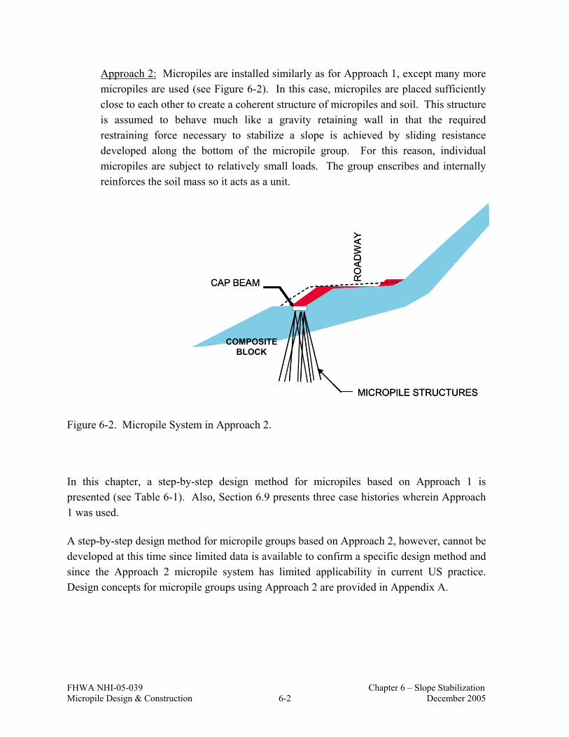
FHWA NHI-05-039 Chapter 6 – Slope Stabilization Micropile Design & Construction 6-2 December 2005
Approach 2: Micropiles are installed similarly as for Approach 1, except many more micropiles are used (see Figure 6-2). In this case, micropiles are placed sufficiently close to each other to create a coherent structure of micropiles and soil. This structure is assumed to behave much like a gravity retaining wall in that the required restraining force necessary to stabilize a slope is achieved by sliding resistance developed along the bottom of the micropile group. For this reason, individual micropiles are subject to relatively small loads. The group enscribes and internally reinforces the soil mass so it acts as a unit.
MICROPILE STRUCTURES
CAP BEAM RO
AD
WAY
COMPOSITEBLOCK
MICROPILE STRUCTURES
CAP BEAM RO
AD
WAY
COMPOSITEBLOCK
Figure 6-2. Micropile System in Approach 2.
In this chapter, a step-by-step design method for micropiles based on Approach 1 is presented (see Table 6-1). Also, Section 6.9 presents three case histories wherein Approach 1 was used.
A step-by-step design method for micropile groups based on Approach 2, however, cannot be developed at this time since limited data is available to confirm a specific design method and since the Approach 2 micropile system has limited applicability in current US practice. Design concepts for micropile groups using Approach 2 are provided in Appendix A.

FHWA NHI-05-039 Chapter 6 – Slope Stabilization Micropile Design & Construction 6-3 December 2005
Table 6-1. Design Steps for Micropiles for Soil Slope Stabilization.
1. Identify project specific constraints and evaluate feasibility 2. Identify performance requirements 3. Review available information and geotechnical data 4. Evaluate factor of safety of existing slope 5. Determine additional force required to obtain target factor of safety
• choose a location for the single vertical micropile within the existing slope • model restraining force (micropile) and perform slope stability analysis • evaluate the stability of the slope away from micropile
6. Select micropile cross section 7. Estimate length of micropile 8. Evaluate bending moment capacity of single vertical micropile 9. Evaluate shear capacity of single vertical micropile 10. Evaluate shear capacity of battered micropile group
• select batter angle for upslope and downslope micropile • determine maximum shear capacity of a single battered micropile • determine maximum shear capacity of battered micropile group
11. Calculate spacing required to provide required force to stabilize the slope 12. Check potential for soil flow between micropiles 13. Perform structural design of concrete cap beam
6.2 STEP 1: IDENTIFY PROJECT SPECIFIC CONSTRAINTS AND EVALUATE MICROPILE FEASIBILITY
Slope stabilization projects in which micoropiles may be feasible are usually located in remote areas or where difficult site access is a concern. Other project constraints common to slope stabilization include:
(1) space restrictions that may include limited ROW, availability of on-site storage for construction materials, limited access for construction equipment, and restrictions on traffic disruption;
(2) interference with above-ground utilities and nearby structures; (3) performing work on an unstable slope (i.e., need to perform any cut/fill operations in
a controlled manner, potential for excess seepage in and around the work area, soil and/or rock fall hazards, etc.);
(4) environmental concerns that may include local policies concerning construction noise, vibration, transportation of material to the site, and protection of animals and plants;

FHWA NHI-05-039 Chapter 6 – Slope Stabilization Micropile Design & Construction 6-4 December 2005
(5) landscape aesthetics such as sensitivity to scars created by access road cuts or excavations;
(6) disposal of rock or soil that is excavated as part of the slope stabilization method; and (7) cost of project.
In assessing the use of micropiles as a means to stabilize a slope, micropiles will most often be compared to other structural slope stabilization measures such as ground anchors, soil nail walls, or driven pile or drilled shafts.
The use of micropiles has come into favor for slope stabilization projects because micropile construction is relatively simple and requires a small work area, and micropiles can be readily installed in areas with limited equipment access, such as for landslides located in hilly, steep, or mountainous areas. However, the implementation of these systems still requires a specialty geotechnical contractor. The other advantages offered by micropiles include, reduced excavation compared to earth retaining systems (i.e., the system is constructed from the top-down, no excavation is required to construct a wall or install anchor supports); improved aesthetics in that the system is completely buried so that there is no visual evidence of an active structural stabilization system; and micropiles can be installed in virtually any ground type. This latter advantage is important for landslide stabilization since, in many cases, an upper competent layer is underlain by soft, wet soil material (comprising the location where landslide movements are occurring) resting on rock. The upper layer may comprise colluvium or talus materials which are known to contain a wide range of soil and rock particle sizes through which installation of driven piles or drilled shafts would be difficult and costly.
The cost-effective use of micropiles will be based on the required forces necessary to stabilize a slope. For example, projects which involve a relatively long landslide (i.e., large failure surface length) or where the depth to the potential slip surface is large, may not be well-suited for micropiles because of the very large restraining forces required to stabilize the slope. It is noted, however, that micropiles can be designed to withstand relatively large loads by battering the micropiles to mobilize axial restraint forces. In some cases, even with battered micropiles, the required loads to be resisted are so large that additional restraint, usually from ground anchors, is required.
For first-order comparisons, micropiles for slope stabilization range in cost from $4,000 to $11,000 per lineal meter of slope ($1,200 to $3,400 per lineal ft of slope). The higher end of the range being for projects involving relatively long micropiles (e.g., in excess of 15 m (50 ft) to reach the top of the slide surface) and where access and other project-specific constraints result in relatively low micropile installation production rates (e.g., less than 90 m (300 ft) per day) and the need for large amounts of rock drilling.

FHWA NHI-05-039 Chapter 6 – Slope Stabilization Micropile Design & Construction 6-5 December 2005
Previous designs and contractor experience indicates that micropiles for slope stabilization will likely only be cost-effective if unbalanced slope forces can be resisted through the placement of a micropile structure at approximately the mid-height of the slope. Design calculations for locating the position of micropiles on a slope is described in this chapter. If a slope stabilization measure would be required to minimize, for example, future downward movements of a roadway near the top of the unstable slope, then a single micropile structure would likely not be sufficient to stabilize the slope since it is possible that the slope would be unstable in front of the micropile structure. In some cases, however, multiple micropile structures could be used but may not be cost effective.
The design method described herein for micropiles is based on the assumption that the portion of the micropiles below the potential slip surface “tie” the slope mass above the potential slip surface to the more competent ground below the potential slip surface. In this sense, the micropiles serve as dowels. Also, the design assumes that concentrated deformations occur at the location of the potential slip surface. With this assumption, maximum bending moments and shears in the micropiles occur near the location of the potential slip surface. Design engineers considering the use of micropiles for a slope stabilization project must review available instrumentation data on slope movements. The design method presented herein requires that movements are occurring at a well-defined critical potential slip surface. As an example, Figure 6-3 shows concentrated lateral soil movements at approximately a depth of 8 m (25 ft). These data are from a landslide in Summit County, Ohio. Where slope movements are less localized, or where more than one potential slip surface may exist (i.e., where a single, well-defined slip surface has not been observed (via instrumentation) or expected (via review of subsurface information)), other slope stabilization measures such as anchored walls should be considered.

FHWA NHI-05-039 Chapter 6 – Slope Stabilization Micropile Design & Construction 6-6 December 2005
Figure 6-3. Concentrated Movements Recorded from Inclinometer at the Slip Surface (after Liang, 2000).
6.3 STEP 2: IDENTIFY PERFORMANCE REQUIREMENTS
The primary performance requirement for a slope stabilization project is for the stabilized slope to meet or exceed a target slope stability factor of safety with respect to static and seismic slope stability. Typical static factors of safety range from 1.3 to 1.5 depending on, for example, whether other structures are supported by the slope and whether only limited geotechnical data is available. For seismic slope stability analyses (based on pseudo-static analysis), a target value of 1.1 is typically used.
Other performance (and/or design) requirements will include:
• prescribed level of corrosion protection for the micropiles; • permissible variation in groundwater levels during construction; • maximum loads that can be carried (as part of load testing); and • allowable stresses for steel and concrete.

FHWA NHI-05-039 Chapter 6 – Slope Stabilization Micropile Design & Construction 6-7 December 2005
It is noted that design of earth slopes (and stabilization of slopes) is not codified in, for example, AASHTO (2002). Design criteria for slopes are typically developed on a project-specific basis.
6.4 STEP 3: REVIEW AVAILABLE INFORMATION AND GEOTECHNICAL DATA
The existing slope conditions should be assessed by review of available information and collection of geotechnical data through a focused subsurface exploration and laboratory testing program. For guidance regarding the planning and execution of subsurface exploration programs for slopes, refer to the Manual on Subsurface Investigations (Mayne et al., 2001) and Geotechnical Engineering Circular (GEC) No. 5 “Evaluation of Soil and Rock Properties” (Sabatini et al., 2002).
The information gathering, subsurface exploration and laboratory testing program should be developed with the goal of obtaining the following information:
Topography of the area. Topographic information for the area of interest is used to develop analysis cross sections for slope stability analysis. If relatively recent topographic maps are not available for the site or if it is known that site topography has been modified since the last ground survey was performed, a ground surface survey of the area should be performed since accurate information on slope geometry is critical for analysis.
Lateral extent of the landslide or potential landslide area. This information can be obtained through observations from a site inspection and through review of aerial photographs (if available). The lateral extent of the area to be stabilized needs to be known to enable potential slip surfaces with the lowest factor of safety to be identified. Usually, multiple parallel cross sections are analyzed using 2-dimensional limit equilibrium methods to determine the slip surface with the minimum slope stability factor of safety. This cross section is used to perform design analyses of the slope.
Subsurface profile and groundwater conditions. The subsurface profile at the location of the critical cross section is developed based on information from historical borings and from borings advanced as part of the slope stabilization project. This exercise is carried out similarly as for other geotechnical features where the development of a subsurface profile is required. Specifically, for slopes stabilized with micropiles, borings should be advanced into the competent materials below the potential slip surface which will serve as the resistance zone for the micropile.

FHWA NHI-05-039 Chapter 6 – Slope Stabilization Micropile Design & Construction 6-8 December 2005
Groundwater conditions within the slope may be determined from the logs of soil borings, piezometer data, and observation wells. This information is used to model pore pressure conditions within the slope. It is specifically noted that the cause of slope movements is oftentimes related to large precipitation events which cause groundwater levels and pore pressures to increase in a slope mass. Where the conditions of the slope at the time of instability are required for analyses (e.g., where back analysis to obtain strength properties is required), it is necessary to develop pore pressure conditions at the time of the slope instability.
The assessment of design groundwater levels (or design pore pressures) should consider the effect that the micropile structure will have on long-term groundwater levels within the slope. Typically, however, the spacing between micropiles is sufficiently large such that the possibility of pore pressure buildup (resulting from a potential hydraulic cutoff effect from the micropile structure) is relatively insignificant. Where project conditions require close micropile spacing and/or where the potential for significant groundwater recharge to the slope area is possible, the Owner should require that seepage analyses be performed that consider the effects of micropile spacing, micropile installation methods (e.g., effect of possible grout travel), precipitation events, and hydraulic conductivity of the slope material. Subsurface drainage systems may be required and/or the proposed micropile system may be designed to resist long-term seepage pressures.
The importance of an accurate assessment of pore pressure conditions within a slope cannot be overemphasized.
Soil and rock parameters for analysis. Material parameters for soil and rock are required for slope stability analyses and for the evaluation of the structural capacity of micropiles (using p-y analyses discussed subsequently). Material parameters required include soil and rock unit weights and shear strength parameters.
Depending on the soil type and access to sampling locations in the slope area, soil and rock sampling may be difficult and obtaining nominally undisturbed soil samples for strength testing may be impossible. In these situations, it is prudent to collect as much index type data as possible (i.e., Atterberg limits, grain size analysis, and moisture content) to establish differences between soil and rock stratum. Based on these data, strength properties would be determined from engineering correlations. Common engineering correlations for soil and rock properties that may be used for micropile slope stabilization assessment are provided in GEC No. 5 (Sabatini et al., 2002).
FHWA NHI-05-039 Chapter 6 – Slope Stabilization Micropile Design & Construction 6-9 December 2005
The use of these and other correlations for geotechnical parameters should be considered primarily for use in preliminary design evaluations and not as a substitute for a comprehensive site investigation, sample collection, and laboratory testing program.
Critical slip surface. Information on the location of the critical slip surface may be obtained from several sources during initial data review. In some cases, especially if the slope has been subject to previous movements, inclinometer data may be available which can be used to locate the critical slip surface. Also, boring logs and other stratigraphic information can be used to locate a potential slip surface. Oftentimes the critical slip surface will be located at the interface just above a competent soil or rock surface where water may be perched. This area becomes saturated and soft and slope movements may be concentrated at this location.
For micropile design, in addition to the requisite slope stability analyses, the location of the critical slip surface is required for laterally loaded pile analyses. As previously introduced, the location of the critical potential slip surface (as determined from slope stability analysis and/or field observations) is used as the location where maximum lateral micropile movement is assumed to occur.
Site Seismicity. As for any other slope, destabilizing forces resulting from seismically-induced ground accelerations need to be considered. This evaluation for slopes is typically performed using a pseudo-static slope stability analysis (see Kavazanjian et al. 1997).
6.5 STEP 4: EVALUATE FACTOR OF SAFETY OF EXISTING SLOPE
Using the information from Step 3, slope stability analysis methods are used to evaluate the slope stability factor of safety for the slope that is to be stabilized. Presumably, this slope is at a slope stability factor of safety of approximately 1.0 (if the slope has undergone significant movements) or may be at a slightly higher factor of safety. From this evaluation, the minimum factor of safety (FSmin) is evaluated. As a result of the analysis, the location of the critical potential slip surface is evaluated.
Analyses are typically performed for the static and seismic case and the results are compared to the target minimum factor of safety (previously discussed). In performing these analyses, estimates of shear strength, subsurface stratigraphy, and pore pressures within the slope mass are developed. A special case includes one in which the slope is known to have failed or have undergone significant downslope movement. By definition, this slope is at a FS = 1.0 at the time of the failure. Micropiles for slope stabilization have been used most commonly with applications involving slope failures (i.e., landslides). The technique used to adjust

FHWA NHI-05-039 Chapter 6 – Slope Stabilization Micropile Design & Construction 6-10 December 2005
shear strength parameters for this case is termed “back-analyses”. Back-analysis techniques involve the following steps:
i. Estimate analysis parameters. If the slope has moved sufficiently, the residual drained friction angle may be used (e.g., c′ = 0, φ′ = φ′r) to model the soil material where these movements have occurred. Figure 6-4 may be used to evaluate φ′r. The use of Atterberg limits data and clay content can be used to assess residual (or large-displacement) drained friction angle for clayey landslide material (see Figure 6-4). For example, based on Figure 6-4, for a landslide material with clay content between 25 and 45 percent and with liquid limit of 60, the residual friction angle is 18 degrees.
(1kPa = 0.145 psi) Note: φ’r = Residual friction angle and CF = Percent clay-particles < 0.002 mm (0.00008 in)
Figure 6-4. Residual Friction Angle for Clayey Soils (after Stark and Eid, 1994).
The shear strength parameters estimated are considered as trial strengths (φtrial and ctrial) in the back-analysis. Representative shear strength parameters for other soil and rock materials (i.e., those above and below soils near the critical potential slip surface) are evaluated based on available information and are usually not adjusted as part of the back analysis.

FHWA NHI-05-039 Chapter 6 – Slope Stabilization Micropile Design & Construction 6-11 December 2005
ii. Perform slope stability analysis. Limit equilibrium slope stability analysis is performed to obtain the factor of safety that corresponds to trial strengths. Slope stability analyses are performed for several analysis cross sections. The best available information for pore pressure values, shear strength, stratigraphy, and topography at the time of the failure is used in the analyses. Also, the location of the failure surface needs to be known with some level of certainty so that analysis results can be compared to actual conditions.
iii. Adjustment of parameters until FS =1.00. If the previous slope stability analyses do not yield FS=1.00, shear strength parameters should be modified and analyses performed. This process is continued until shear strength parameters result in a corresponding FS = 1.00 result. It is important to note that shear strength represents only one of the unknowns in the analysis. Pore pressures and location of the critical failure surface (at the time of failure) need to be understood and hence their potential uncertainty should also be considered when varying parameters. A back analysis that produces FS = 1.00, but includes a calculated critical failure surface that is not consistent with that observed in the field should not be relied upon. All relevant parameters need to be consistent with observed results.
For the case where the existing slope may have a factor of safety greater than 1.0, but where the factor of safety is less than a target value, shear strengths and groundwater elevations should be evaluated as described in Design Step 3. In these cases, the location of the critical slip surface needs to be estimated based on available data. Slope stability analyses to evaluate FSmin should be performed considering circular and planar slip surfaces. Subsurface stratigraphy information should be used to evaluate the reasonableness of the calculated potential slip surface.
6.6 DESIGN CONCEPTS FOR MICROPILES USED FOR SLOPE STABILIZATION
6.6.1 Overview
At this stage in the design process, an existing slope has been shown to be either unstable or marginally stable with a calculated slope stability factor of safety less than a target value. The remaining steps of the design process comprise designing a micropile system to improve or otherwise stabilize the slope.
The steps specific to the geotechnical and structural design of micropiles used for slopes is outside the typical design practice for most geotechnical engineers. For this reason, this

FHWA NHI-05-039 Chapter 6 – Slope Stabilization Micropile Design & Construction 6-12 December 2005
section provides background information on load transfer mechanisms and analysis methods used for Design Steps 5 through 13. The complete design of a micropile stabilized slope is demonstrated in Section 6.7.
6.6.2 Evaluating the Additional Force Required to Obtain Target Factor of Safety
Micropiles used for slopes are designed to prevent downward movement of the slope mass above the potential slip surface. The micropiles must be capable of providing the force required to stabilize the slope. This force is the force required to increase the factor of safety of the slope from an existing value to a target value.
Slope stability analysis programs are used to determine this additional force (Hreq). The slope stability analyses are performed in three stages: (1) a location is chosen for the micropiles; (2) the micropiles are modeled explicitly in the slope stability analysis to determine the required restraining force; and (3) the stability of the slope away from the micropile is evaluated by performing additional slope stability analysis.
6.6.2.1 Micropile Location Within Slope Cross Section
The magnitude of Hreq will vary depending on the location of the micropile within the slope. This affect is demonstrated using the example slope geometry provided in Figure 6-5.
Several analyses were performed in which the location of a single micropile was adjusted within the cross section. At each location, the shear force provided by the micropile was increased until a target factor of safety (FSmin) of 1.3 was achieved for the slope. The results of the analyses are shown in Figure 6-6 and these results indicate that, for this example, if the micropile is placed at or near the toe of the slope or at or near the crest of the slope, the use of a micropile structure at these locations would be ineffective. In other words, regardless of the magnitude of force that the micropiles could develop, the target factor of safety (i.e., FSmin = 1.3) could never be achieved (see Figures 6-7 and 6-8 for the most critical slip surface).
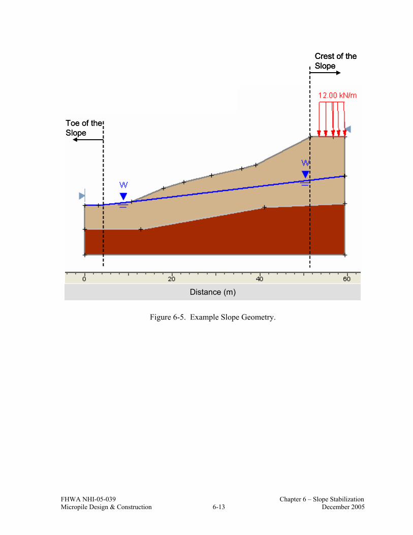
FHWA NHI-05-039 Chapter 6 – Slope Stabilization Micropile Design & Construction 6-13 December 2005
Toe of the Slope
Crest of the Slope
Distance (m)
Toe of the Slope
Crest of the Slope
Toe of the Slope
Crest of the Slope
Distance (m)
Figure 6-5. Example Slope Geometry.

FHW
A N
HI-
05-0
39
C
hapt
er 6
– S
lope
Sta
biliz
atio
n M
icro
pile
Des
ign
& C
onst
ruct
ion
6-14
D
ecem
ber 2
005
600
610
620
630
640
650
660
670
680
690
700
04
812
1620
2428
3236
4044
4852
5660
DIS
TA
NC
E (m
)
FORCE REQUIRED FOR FS = 1.3 (kN/m)
FS <
1.3
FS <
1.3
Toe
of th
e Sl
ope
Cre
st o
f the
Sl
ope
Not
e: 1
m =
3.2
8 ft
and
1 kN
/m =
68.
53 lb
/ft
Figu
re 6
-6.
Rel
atio
nshi
p be
twee
n Fo
rce
Req
uire
d Fo
r FS
= 1.
3 an
d Lo
catio
n of
the
Mic
ropi
le.

FHWA NHI-05-039 Chapter 6 – Slope Stabilization Micropile Design & Construction 6-15 December 2005
Figure 6-7. Effect of Micropile Placed Too Far Upslope (FSmin < 1.3).
Figure 6-8. Effect of Micropile Placed Too Far Downslope (FSmin < 1.3).

FHWA NHI-05-039 Chapter 6 – Slope Stabilization Micropile Design & Construction 6-16 December 2005
The results of the above example indicate that the maximum benefits from micropiles correspond to a micropile structure placed in the vicinity of the middle of the slope.
6.6.2.2 Methods to Model Resisting Force from a Micropile
While it is recognized that micropile structures for slope stabilization will typically include a battered upslope “leg” and a battered downslope “leg” connected at the ground surface via a concrete beam (Figure 6-9), the micropile structure is modeled considering a single vertical micropile from the ground surface (at the design cap beam location) to a sufficient depth into a competent layer (see Figure 6-10). In subsequent design steps, the shear capacity, inclination, and the number of micropiles required to resist Hreq is evaluated.
Slope stability input files generated in Design Step 4 are typically modified in one of two ways to model the effects of a single vertical micropile, as described below.
• Approach 1: The shear resistance provided by the single vertical micropile, Hreq, can be modeled as a relatively large cohesive shear strength assigned to the soil layer where the micropile crosses the potential slip surface. By selecting a width of say 0.5 m, the slope stability analysis program will develop a single slice with a width of 0.5 m having the relatively large cohesive shear strength. The relationship between Hreq and cohesive strength is shown in Figure 6-11 for this approach. It should be noted Hreq is oriented at the same angle as the bottom of the slice. Repeat the slope stability analyses and change the cohesive strength until a factor of safety equal to the target value is obtained.
• Approach 2: Some slope stability software packages enable the user to directly input a micropile restraining force at any given location. With this approach, it is not necessary to indirectly obtain the restraining force via the introduction of a thin soil layer with a relatively large cohesive strength. Repeat the slope stability analyses and change the value for the restraining force until a factor of safety equal to the target value is obtained.

FHWA NHI-05-039 Chapter 6 – Slope Stabilization Micropile Design & Construction 6-17 December 2005
Micropile cap beam
Battered downslope “leg”
Battered upslope “leg”
Micropile cap beam
Battered downslope “leg”
Battered upslope “leg”
Figure 6-9. Micropiles with Battered Uplsope Leg and Battered Downslope Leg (modified after Hasenkamp, 1999).
Existing Slope Surface
Slip Surface
Direction of Slope Movement
Unstable Slope Mass
Cap Beam
Vertical Micropile
Micropile Resistance Length
Competent Soil or Bedrock
Existing Slope Surface
Slip Surface
Direction of Slope Movement
Unstable Slope Mass
Cap Beam
Vertical Micropile
Micropile Resistance Length
Competent Soil or Bedrock
Figure 6-10. Single Vertical Micropile Model for Design Analyses.

FHWA NHI-05-039 Chapter 6 – Slope Stabilization Micropile Design & Construction 6-18 December 2005
w
L
α
c
w
L
α
c
L cH req ×=
αcos1 w cH req ××=
Figure 6-11. Relationship Between Hreq and Cohesive Strength for Micropile Analysis Model.
c = Cohesive strength w = Width of the slice L = Length of the slice α = Angle of the slice base Hreq = Required shear force

FHWA NHI-05-039 Chapter 6 – Slope Stabilization Micropile Design & Construction 6-19 December 2005
6.6.2.3 Evaluating Slope Stability Away From Micropile
Results of the previous slope stability analysis provide the location and the required restraining force for the slope to achieve the target factor of safety. However, it is possible that slip surfaces away from the micropile may have factor of safety values less than the target value and therefore, additional slope stability analyses should be performed. For these analyses, the presence of the micropile is ignored by setting the search limits for potential slip surfaces located entirely upslope of the micropile and for potential slip surface located entirely downslope of the micropile (see Figure 6-12).
Search limits set downslope of micropile
Search limits set upslope of micropile
Micropile structure
Search limits set downslope of micropile
Search limits set upslope of micropile
Micropile structure
Figure 6-12. Slope Stability Analysis Search Limits Away From Micropile Location.
Specific practical issues are associated with the evaluation of downslope stability (as for Figure 6-13). If, for example, a roadway is located at the toe of the slope, then it is possible that future roadway widening would require excavation at the toe of the slope. Excavation near the toe of the slope may also be associated with certain long-term slope maintenance activities. For many earth retaining structures used to stabilize slopes, the resistance provided by soil in front of the wall (i.e., passive soil resistance) is conservatively neglected because of the possibility that this material would be removed at a later date. This design assumption can be adequately addressed with many earth retaining systems. For micropiles, it is explicitly noted that the assumption of zero passive soil resistance in front of the micropile is not considered using the design method presented herein. If slope material in front of the micropile were to move away from the structure as a result of instability or if soil

FHWA NHI-05-039 Chapter 6 – Slope Stabilization Micropile Design & Construction 6-20 December 2005
were removed as part of a maintenance activity, it is likely that the micropile structure would experience excessive deflection or structural failure of the downslope micropiles due to the loss of lateral support.
Competent Soil or Bedrock
Stabilized Soil Mass
Cap Beam
Limits of Future Excavation
Critical Slip Surface
Competent Soil or Bedrock
Stabilized Soil Mass
Cap Beam
Limits of Future Excavation
Critical Slip Surface
Figure 6-13. Potential Instability Resulting from Future Excavation.
There are two approaches to address these issues:
• As part of the design submittal, the Owner can require calculations to be performed which establish the maximum amount of excavation that could be performed in front of the micropiles. This critical geometry would show the greatest length of excavation into the slope such that a minimum factor of safety is maintained and so that the soil in front of the micropile structure remains stable thus providing the required lateral support to the front row of micropiles. Furthermore, it is recommended herein that this design check be performed and the information be

FHWA NHI-05-039 Chapter 6 – Slope Stabilization Micropile Design & Construction 6-21 December 2005
provided to the Owner, regardless of whether such a check is specifically requested in the Contract Documents.
• Where micropile structures are used, the Owner may fence off the area and post signs alerting that excavation should not be performed in the area.
6.6.3 Load Transfer in Micropiles
Micropiles resist unstable slope forces through a combination of axial resistance developed at the grout-to-ground interface both above and below the potential slip surface and structural (i.e., shear and bending) resistance. As mentioned earlier, the maximum lateral micropile movement is assumed to occur near the elevation of the critical potential slip surface. This is a reasonable assumption for micropiles since micropiles are relatively flexible. An example showing the resultant axial force and bending moment diagrams for an upslope leg and downslope leg of micropiles used for a slope stabilization project in Littleville, Alabama (Brown and Chancellor, 1997) is presented in Figure 6-14.
The capacity of individual micropiles used for slope stabilization can be increased significantly by designing the micropiles to be inclined or “battered” relative to the critical potential slip surface. If the micropile is battered, slope movements will result in the tendency for the micropile to be “pulled” away from the slip surface resulting in axial tension forces or to be “pushed” towards the slip surface resulting in axial compression forces. These forces are mobilized as side resistance at the grout-to-ground interface. For micropile structures without ground anchors used to stabilize landslides, the upslope leg will typically be in tension and the downslope leg will typically be in compression.
The maximum axial force in a micropile will occur near the location of the critical potential slip surface. In this sense, the development of axial resistance is similar to that for soil nails. For the micropiles to develop the required axial resistance for design, the micropile must be embedded sufficiently into the ground below the critical slip surface to prevent micropile

FHW
A N
HI-
05-0
39
C
hapt
er 6
– S
lope
Sta
biliz
atio
n M
icro
pile
Des
ign
& C
onst
ruct
ion
6-22
D
ecem
ber 2
005
(a)
(b)
Not
e: 1
kip
= 4
.448
kN
and
1 ft
= 0
.304
8 m
Figu
re 6
-14.
Exa
mpl
e R
esul
tant
Axi
al F
orce
and
Ben
ding
Mom
ent D
iagr
ams f
or (a
) Dow
nslo
pe a
nd (b
) Ups
lope
Mic
ropi
le (a
fter
Bro
wn
and
Cha
ncel
lor,
1997
).

FHWA NHI-05-039 Chapter 6 – Slope Stabilization Micropile Design & Construction 6-23 December 2005
failure through pullout (if the micropile is loaded in tension) or failure as a result of insufficient bearing capacity (if the micropile is loaded in compression). In other words, the side resistance capacity of the micropile below the potential slip surface must be sufficient to resist axial forces developed above the potential slip surface (see Figure 6-15).
The axial force required to be resisted by the micropile below the potential slip surface is assumed to be equal to the ultimate side resistance of the micropile that could develop above the failure surface with a factor of safety. The ultimate side resistance of the micropile above the failure surface, Pult, can be calculated as:
d L P aboveabove-bondult ×××= πα (Eq. 6-1)
where αbond-above is the grout-to-ground ultimate bond strength above the critical slip surface, Labove is the length of the micropile from the slip surface to the bottom of the cap beam, and d is the diameter of the micropile. The value for αbond-above is estimated using Table 5-3.
In addition to axial resistance, micropiles develop flexural resistance. The design objective therefore, is to select a micropile system with sufficient structural capacity to resist the unbalanced slope force (i.e., Hreq) without structural failure of the micropile in combined axial loading and bending.
Therefore, the required length of the micropile below the slip surface, Lbelow, is calculated as:
FS d
PL
below-bond
ultbelow ×
××=
πα (Eq. 6-2)
where Pult is calculated using Eq. 6-1, αbond-below is the grout-to-ground ultimate bond strength below the critical slip surface and is estimated using Table 5-3. A FS = 2.0 should be used in Eq. 6-2.

FHWA NHI-05-039 Chapter 6 – Slope Stabilization Micropile Design & Construction 6-24 December 2005
Figure 6-15. (a) Micropile Resistance Length Not Sufficient to Prevent Pullout and (b) Micropile Resistance Length Sufficient to Prevent Pullout.
Currently, load testing of micropiles for slope stabilization projects is not commonplace; therefore required micropile side resistance has relied exclusively on contractor experience in similar ground. This document, however, recommends that load testing be performed. Load testing requirements for slope stabilization projects is provided in Chapter 7.
FHWA NHI-05-039 Chapter 6 – Slope Stabilization Micropile Design & Construction 6-25 December 2005
6.6.4 Bending Moment and Shear Capacity of Single Vertical Micropile
6.6.4.1 Evaluation of Bending Moment Capacity of Single Vertical Micropile
The shear resistance of a micropile corresponds to the maximum shear force that can be applied to the micropile that results in a maximum bending moment within the micropile (at any location) to be just equal to the ultimate bending moment of the micropile.
To evaluate the shear resistance of a single micropile, the ultimate bending moment (Mult) of the single micropile is checked. The ultimate bending moment of a single vertical micropile can be conveniently evaluated using the computer program LPILE (2005) or other soil-structure interaction programs used for the analysis of laterally loaded piles and shafts. Because micropiles are battered, they develop axial resistance through side friction between the grout and the ground. Since the bending moment capacity of a micropile (or any other structural section) varies depending on the applied axial load, the bending moment capacity of a single micropile is checked for two limiting axial load conditions: (1) axial load equal to zero, P = 0; and (2) axial load equal to the ultimate side resistance of the micropile, P = Pult
(where Pult is calculated using Eq. 6-1).
In these analyses, the shear capacity corresponding to the ultimate bending moment in the micropile is used. The rationale for this is described in Section 6.8.
As previously discussed, axial loads in micropiles may be in tension or compression. In general, the uphill micropile will be in tension and the downhill micropile will be in compression. However, where ground anchors are incorporated into the micropile structure, the direction of the axial load for individual micropiles may change depending on ground anchor stressing and lock-off loads. For this reason, Mult should be evaluated for the P = Pult case considering that this axial load is applied in compression and in tension. The design would then be based on the case that provides the lower Mult; and therefore the lower value for available micropile shear resistance.
6.6.4.2 Evaluation of Shear Capacity of Single Vertical Micropile
The maximum shear force that the micropile can carry corresponds to that shear force applied at the elevation of the slip surface that results in a calculated maximum bending moment in the micropile that is equal to Mult. This maximum bending moment is affected by the stiffness (i.e., p-y response) of the ground above and below the potential slip surface and the flexural rigidity of the micropile. This evaluation can be performed using laterally loaded pile analyses for single elements such as that provided in LPILE.

FHWA NHI-05-039 Chapter 6 – Slope Stabilization Micropile Design & Construction 6-26 December 2005
The shear force capacity of a single vertical micropile is determined by analyzing separately the portion of the micropile above the potential slip surface (termed the “up” analysis) and the portion of the micropile below the potential slip surface (termed the “down” analysis). This requires, for the up analysis, adjustment of the location of previously determined p-y curves relative to the top of the pile in the analysis. Figure 6-16 shows p-y curves for the entire length of the micropile and Figure 6-17 shows how they are adjusted for the up and down analyses.
The iterative process to determine the maximum shear capacity requires performing up and down analyses as a set. Both analyses are performed for minimum axial resistance conditions (i.e., P = 0) first and then for maximum axial resistance conditions (i.e., P = Pult). The boundary shear forces and bending moments applied at the slip surface location, although applied as boundary conditions in the analyses, are actually internal forces and bending moments within the micropile. Because of this, specific criteria need to be satisfied when comparing the up and down analyses results to evaluate the correctness of the analyses. These are described below:
• The same value for axial load is used for both the up and down analyses. • The input shear force magnitude and direction applied at the slip surface location is
the same for the up and down analyses. • The input bending moment applied as a boundary condition should be equal in
magnitude and opposite in sign for the up and down analyses. • The calculated slope of the micropile head at the slip surface should be the same for
the up and down analyses. • The head of the micropile is modeled as free.
Figure 6-18 shows calculated bending moment diagrams for a micropile using the up and down analyses. These analyses show the iterative process wherein the analysis is complete for the case where Mmax = Mult and the pile head slope from the up and down analysis is equivalent. For Analysis 1, a bending moment at the slip surface location of 40 kN-m is assumed. With this, it is seen that the calculated slopes of the micropile from the up and down analysis are not the same. This implies a discontinuity in slope at the slip surface location, which is not possible. For the next iteration, a bending moment of 87 kN-m is assumed. Inspection of the table in Figure 6-18 indicates that for this slip surface location bending moment, the pile head slope from the up and down analysis are equivalent; it is also seen that the maximum calculated bending moment of 161 kN-m occurs below the slip surface and is approximately equal to the ultimate bending moment based on the structural capacity of the micropile section assumed. Thus, the analysis is complete. This procedure is demonstrated in the Design Example provided in Section 6.7.6.

FHWA NHI-05-039 Chapter 6 – Slope Stabilization Micropile Design & Construction 6-27 December 2005
Slip Surface
Top of the Micropile
Bottom of the Micropile
Ground Surface
y
p
y
p
y
p
y
p
y
p
p-y (d1)
p-y (d5)
p-y (d4)
p-y (d3)
p-y (d2)
Labove
Lbelow
Cap Beam
d1
d2
d3
d4
d5
Figure 6-16. An Example Distribution of p-y Curves with Depth Obtained from Laterally Loaded Pile Analysis.

FHWA NHI-05-039 Chapter 6 – Slope Stabilization Micropile Design & Construction 6-28 December 2005
y
p
y
p
p
p-y (d3)
p-y (d1)
p-y (d2)
Micropile above the slip surface
d3
y
d2
d1
Labove
Micropile below the slip surface
d4
d5Lbelow
y
p
y
p p-y (d5)
p-y (d4)
Figure 6-17. Utilizing p-y Curves Obtained From Laterally Loaded Pile Analysis in: (a) Up Analysis and (b) Down Analysis.
(a)
(b)

FHWA NHI-05-039 Chapter 6 – Slope Stabilization Micropile Design & Construction 6-29 December 2005
Slip Surface Location0
1
2
3
4
5
-200 -150 -100 -50 0 50 100 150 200
Bending Moment (kN.m)
Dis
tanc
e Fr
om S
lip S
urfa
ce (m
)
Analysis 1Analysis 2
UP ANALYSIS
M
-3
-2
-1
0-200 -150 -100 -50 0 50 100 150 200M
Slip Surface Location
Mult = 161.3 kN.m
DOWN ANALYSIS
Slip Surface Location0
1
2
3
4
5
-200 -150 -100 -50 0 50 100 150 200
Bending Moment (kN.m)
Dis
tanc
e Fr
om S
lip S
urfa
ce (m
)
Analysis 1Analysis 2
UP ANALYSIS
M
-3
-2
-1
0-200 -150 -100 -50 0 50 100 150 200M
Slip Surface Location
Mult = 161.3 kN.m
DOWN ANALYSIS
Analysis No. M (kN.m) Mmax (kN.m) Pile Head Slope (Up)
Pile Head Slope (Down)
1 40 162.98 - 0.064 - 0.025 2 87 161.00 -0.037 -0.037
Note: M: Applied bending moment. 1 kN.m = 0.737 k.ft
Figure 6-18. Example of Calculated Bending Moment Diagrams for Up and Down Analyses.

FHWA NHI-05-039 Chapter 6 – Slope Stabilization Micropile Design & Construction 6-30 December 2005
6.6.5 Shear Capacity of Battered Micropile Group
The maximum lateral force (Hult) that an inclined (or battered) single micropile can resist at the location of the critical slip surface is evaluated in this step. For the analysis, the effects of a non-horizontal slip surface are also addressed. The value for Hult which will be compared to the required force to provide the target factor of safety, i.e., Hreq, is the sum of the individual Hult values from each battered micropile in the cross section.
The assumed forces acting on a micropile are shown in Figure 6-19 for the case of a vertical micropile (where axial resistance is assumed to be zero, i.e., P=0) and for an inclined micropile (where axial resistance is assumed to be equal to the ultimate axial resistance provided by the ground above the slip surface, i.e., P=Pult). The inclination angle (ψ) may be defined as the angle between the slip surface and the vertical axis of the pile.
Summing the shear (Q) and axial (P) forces shown in Figure 6-19b in the x and y direction results in the following:
ψsin V - cosψ H Q = (Eq. 6-3)
sinψ H cosψ V P += (Eq. 6-4)
These equations can be solved simultaneously to provide the lateral pile load (along the slip surface):
sinψ P cosψ Q H += (Eq. 6-5)
This lateral pile load, H, is coincident with the orientation of Hreq (see Figure 6-11). Since the purpose of this analysis is to evaluate the ultimate capacity of the micropile, corresponding ultimate values for P and Q in Eq. 6-5 are selected. The minimum axial resistance of a single micropile is zero and the maximum axial resistance is assumed to equal Pult. Because Eq. 6-5 is a function of the inclination of the micropile relative to the slip surface, it is necessary to select a range of inclination angles for which the analyses corresponding to P=0 is valid and for which the analyses corresponding to P=Pult is valid. According to Poulos and Davis (1980), Pult may be assumed to develop in a pile that is inclined at approximately 30 degrees. Therefore, Q and P in Eq. 6-5 are defined as:
For ψ = 0o → P = 0 and Q = QP=0; therefore Hult = QP=0 (Eq. 6-6)
For ψ ≥ 30o → P = Pult and Q = QP=Pult; therefore Hult = QP=Pult cosψ + Pult sin ψ (Eq. 6-7)

FHWA NHI-05-039 Chapter 6 – Slope Stabilization Micropile Design & Construction 6-31 December 2005
Although axial resistance of micropiles should be mobilized even at very small inclination angles, it is conservative to assume that axial resistance is not mobilized until a nominal amount of inclination is achieved. Moreover, relying on axial resistance at small inclination angles implies a level of certainty in the angle of the slip surface (i.e., slope of the failure surface) which can probably not be achieved practically through subsurface investigation techniques; the accurate assessment of the failure surface angle may be difficult to achieve.
Figure 6-19. Forces Acting On (a) Vertical and (b) Inclined Micropile Along The Slip Surface.
(a)
Slip surfaceP = 0
QP=0
y-axis
x-axis
Slip surface
H
V
QP=Pult
P = Pult
ψ
y-axisx-axis
(b)
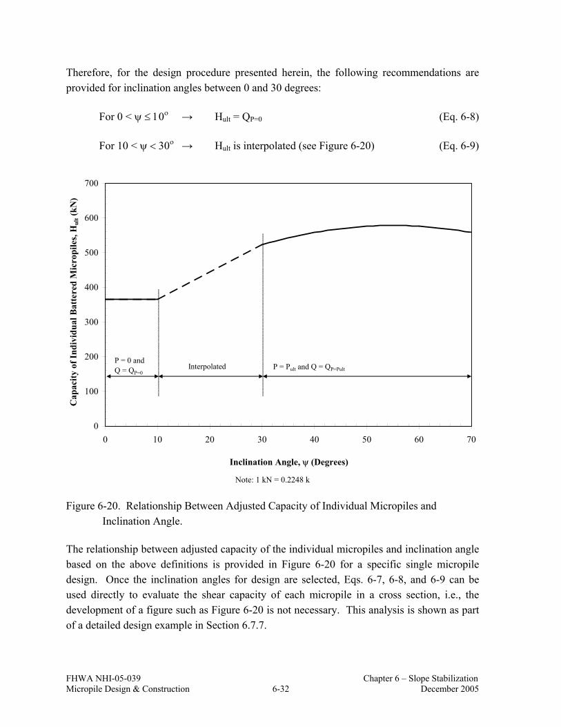
FHWA NHI-05-039 Chapter 6 – Slope Stabilization Micropile Design & Construction 6-32 December 2005
Therefore, for the design procedure presented herein, the following recommendations are provided for inclination angles between 0 and 30 degrees:
For 0 < ψ ≤ 10ο → Hult = QP=0 (Eq. 6-8)
For 10 < ψ < 30ο → Hult is interpolated (see Figure 6-20) (Eq. 6-9)
0
100
200
300
400
500
600
700
0 10 20 30 40 50 60 70
Inclination Angle, ψ (Degrees)
Cap
acity
of I
ndiv
idua
l Bat
tere
d M
icro
pile
s, H
ult (
kN)
P = 0 and Q = QP=0
P = Pult and Q = QP=PultInterpolated
Note: 1 kN = 0.2248 k
Figure 6-20. Relationship Between Adjusted Capacity of Individual Micropiles and Inclination Angle.
The relationship between adjusted capacity of the individual micropiles and inclination angle based on the above definitions is provided in Figure 6-20 for a specific single micropile design. Once the inclination angles for design are selected, Eqs. 6-7, 6-8, and 6-9 can be used directly to evaluate the shear capacity of each micropile in a cross section, i.e., the development of a figure such as Figure 6-20 is not necessary. This analysis is shown as part of a detailed design example in Section 6.7.7.

FHWA NHI-05-039 Chapter 6 – Slope Stabilization Micropile Design & Construction 6-33 December 2005
The inclination angle ψ is defined as the angle between the axis perpendicular to the slip surface and the micropile axis or as the angle between the axis perpendicular to the micropile axis and the slip surface (Figure 6-21). Solutions for positive and negative inclination angles are identical for Eqs. 6-3 and 6-4 (Poulos and Davis, 1980). Therefore, ψ should be written as positive in Eq. 6-5 regardless of its sign.
Using Eq. 6-5, the capacity of the upslope micropile and the downslope micropile can be evaluated using the criteria presented concerning appropriate values for Q and P and depending on the micropile inclination angle,ψ. The inclination angle should be assessed at the location where each of the two micropiles crosses the slip surface. The combined capacity of the upslope and downslope micropile is determined as:
)(ult)(ultpair-ult dsusH H H ΨΨ += (Eq. 6-10)
where ψus is the inclination angle for the upslope micropile and ψds is the inclination angle for the downslope micropile.
6.6.6 Spacing Required to Provide Required Force to Stabilize the Slope
Figure 6-22 shows a detail of a typical micropile layout at the cap beam location. The magnitude of resisting force provided by the micropiles on a per unit length of cap beam basis must be at least equal to Hreq (calculated from slope stability analysis in Design Step 5). Also, the distance between individual micropiles along the cap beam (Soffset) must be large enough to permit ease of construction of the micropile elements.
The shear capacity of the battered upslope micropile (Hult(Ψus)) and battered downslope micropile (Hult(Ψds)) are evaluated using Eq. 6-5 and the combined capacity of the upslope and downslope micropile (Hult-pair) is calculated using Eq. 6-10. From this, Smax (see Figure 6-22) may be evaluated as:
req
pair-ultmax H
H S = (Eq. 6-11)

FHWA NHI-05-039 Chapter 6 – Slope Stabilization Micropile Design & Construction 6-34 December 2005
ψ
Slip surface
Axis perpendicular to slip surface
ψSlip surface
Axis perpendicular to pile axis
MicropileMicropile
(a)
ψ
Slip surface
Axis perpendicular to slip surface
Micropile
ψ
Slip surface
Axis perpendicular to pile axis
Micropile
(b)
Figure 6-21. Definition of Inclination Angle When (a) Slip Surface is Horizontal and (b) Slip Surface is not Horizontal.

FHWA NHI-05-039 Chapter 6 – Slope Stabilization Micropile Design & Construction 6-35 December 2005
Notes: Soffset is the spacing between two micropiles
Smax is the spacing between two upslope or downslope micropiles
Figure 6-22. Spacing Between Micropiles.
6.6.7 Potential for Soil Flow Between Micropiles
If micropiles are spaced too far apart and/or if the soil above the slip surface is very weak, there is a potential for soil material to move in-between adjacent micropiles (Figure 6-23). This failure mechanism has been termed plastic flow. Ito and Matsui (1975) developed a theory to evaluate plastic flow between piles. The lateral force per unit thickness of soil acting on the micropile, q is calculated as (Hassiotis et al., 1997):
Soffset
Soffset
Soffset Smax
Smax
Micropile at upslope leg
Pile cap
Micropile at downslope leg
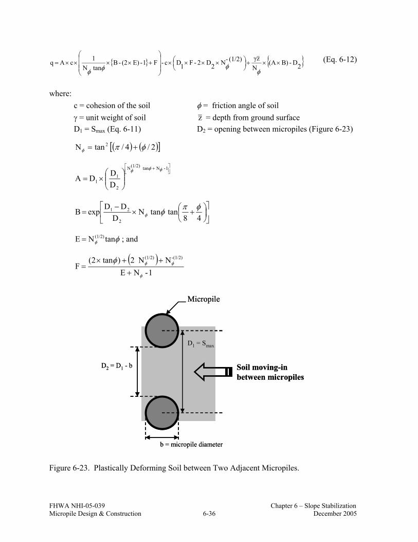
FHWA NHI-05-039 Chapter 6 – Slope Stabilization Micropile Design & Construction 6-36 December 2005
{ } { }2D - B) (A N
zγ(1/2)-N 2D 2- F 1D c-F1-E) (2-B tanN1 c A q ××+
××××
+××××=
φφφφ
(Eq. 6-12)
where: c = cohesion of the soil φ = friction angle of soil γ = unit weight of soil z = depth from ground surface D1 = Smax (Eq. 6-11) D2 = opening between micropiles (Figure 6-23)
( ) ( )[ ]2/4/ tanN 2 φπφ +=
+
×=
1 - N tan(1/2)N
2
11 D
D D Aφφφ
+×
−=
48tan tanN
DDDexp B
2
21 φπφφ
φφ tanN E (1/2)= ; and
( )
1- N ENN 2 ) tan 2(
F-(1/2)(1/2)
φ
φφφ+
++×=
Micropile
D1 = Smax
Soil moving-inbetween micropiles
D2 = D1 - b
b = micropile diameter
Micropile
D1 = Smax
Soil moving-inbetween micropiles
D2 = D1 - b
b = micropile diameter
Figure 6-23. Plastically Deforming Soil between Two Adjacent Micropiles.

FHWA NHI-05-039 Chapter 6 – Slope Stabilization Micropile Design & Construction 6-37 December 2005
The ultimate horizontal force acting on the micropile due to soil movement between adjacent micropiles, Hult-soil/pile is the value for q integrated over the length of the micropile from the slip surface to the cap beam. An example spreadsheet showing this procedure is presented is presented in Section 6.7.9.
To evaluate the spacing between micropiles, the calculated Hult-soil/pile is compared to the average resistance provided by the upslope and downslope pair (Hult-pair/2) as shown below:
• If the plastic flow conditions are satisfied, then Smax previously calculated using Eq. 6-11 does not need to be reduced.
• If Hult-soil/pile < Hult-pair/2, then plastic flow conditions govern and Smax should be reduced. The plastic flow analysis should be repeated based on the new pile spacing corresponding to the reduced Smax. The final design spacing should be selected as the spacing that satisfies Hult-soil/pile ≥ Hult-pair/2.
6.7 DESIGN EXAMPLE FOR SLOPE STABILIZATION WITH MICROPILES
This section provides a complete design example for micropiles used for slope stabilization. The problem comprises stabilizing an embankment that exhibits creep movements particularly during rainy periods. The cross section of the embankment and subsurface information is shown in Figure 6-24.
The roadway surcharge for design is 12 kPa. Right-of-way limitations preclude the use of a berm to stabilize the embankment. For this example, it is assumed that micropiles have been determined to be the best solution to meet the project constraints.
Subsurface conditions are illustrated on Figure 6-24. The slope consists of silty clay overlying calcareous siltstone. Based on laboratory test results, the unit weight of the silty clay is estimated to be 21.2 kN/m3 (134.9 pcf) and calcareous siltstone is estimated to be 23.0 kN/m3 (146.4 pcf). Based on the Atterberg limits results, the silty clay has a liquid limit of 60 and hydrometer results indicate that the silty clay has up to 30 percent clay size material. Shear strength test results for the bedrock indicate a friction angle of 23 degrees with a cohesion intercept of 480 kPa (69.65 psi).

FHW
A N
HI-
05-0
39
C
hapt
er 6
– S
lope
Sta
biliz
atio
n M
icro
pile
Des
ign
& C
onst
ruct
ion
6-38
D
ecem
ber 2
005
1020 030
1020
030
5060
40
Y DIRECTION (METERS)
X D
IRE
CT
ION
(MET
ER
S)
2m12
kPa
BED
RO
CK
CA
LCA
REO
US
SILT
STO
NE
APPR
OXI
MAT
E TO
P O
F RO
CK
LIM
ITS
OF
RIG
HT
OF
WAY
APPR
OXI
MAT
E EX
ISTI
NG
GRO
UND
SU
RFAC
E
CRI
TIC
AL S
LIP
SURF
ACE
N(B
LOW
S/0.
3m)
1520 45 40 10
60/0
.2
N(B
LOW
S/0.
3m)
6 38 60/0
.1
16 46 46 26 25
N(B
LOW
S/0.
3m)
26 30 11 11 35 38 22 60/0
.1
60/0
.1
60/0
.3H
AR
D R
ED A
ND
BR
OW
NSI
LTY
CLA
Y
FILL
RED
STI
FF T
O H
AR
DR
ED S
ILTY
CLA
YW
ITH
BO
ULD
ERS
Figu
re 6
-24.
Slo
pe G
eom
etry
and
Sub
surf
ace
Info
rmat
ion
for t
he D
esig
n Ex
ampl
e.

FHWA NHI-05-039 Chapter 6 – Slope Stabilization Micropile Design & Construction 6-39 December 2005
The critical slip surface location was identified via observations from surficial features (i.e., scarp location at embankment crest and heaving near toe) and from preliminary slope stability analyses.
6.7.1 STEP 4: Evaluate Factor of Safety of Existing Slope
Perform slope stability analysis to compute the minimum factor of safety of the slope (FSmin). Computer programs such as XSTABL, SLIDE, or others can be used to perform the analyses. When performing slope stability analyses, methods such as Simplified Janbu, Simplified Bishop, or Spencer are used.
Because this slope had previously undergone movements, it was assumed that the existing factor of safety of the slope is 1.0. A back-analysis is performed to estimate the shear strength parameters of the silty clay that correspond to FS = 1.0. Back-analysis is performed following the steps presented below:
i. Estimate shear strength parameters. Because the slope has moved sufficiently, the residual drained friction angle can be used (e.g., φ′ = φ′r) to model the soil material where these movements have occurred. For the back-analysis, the shear strength parameters estimated at this stage are considered as trial strengths (φtrial and ctrial).
Using Figure 6-4, with LL=60 and a clay fraction of 30 percent, results in φ'r equal to 18o (i.e., φtrial = 18o). The cohesion of the same soil layer was assumed to be 25 kPa (3.63 psi) (i.e., ctrial = 25 kPa) based on previous experience with these materials.
Slope stability analyses were performed using the computer program SLIDE and Spencer’s limit equilibrium method. The FS of the slope based on trial strengths (i.e., φtrial = 18o and ctrial = 25 kPa) is 1.67 (Figure 6-25).
The trial shear strength parameters were modified using Eqs. 6-13 and 6-14:

FHWA NHI-05-039 Chapter 6 – Slope Stabilization Micropile Design & Construction 6-40 December 2005
Bedrock
Silty Clay
Bedrock
Silty Clay
Figure 6-25. FSmin Determined from Trial Shear Strength Parameters.
( ) ( ){ } FS
trialtantanmodifiedtrial
1 φφ −= (Eq. 6-13)
( ) ( )trialFS
trialmodified cc = (Eq. 6-14)
Based on the above, φ’ (modified) is found to be 11o and c’ (modified) is 15 kPa (2.18 psi).
The back-analysis method presented above should be used with caution. As mentioned before, the calculated critical failure surface needs to be compared against the observed critical failure surface in the field. Also, the use of a nonzero effective stress cohesion intercept should be used with caution as deformations tend to reduce this cohesion.

FHWA NHI-05-039 Chapter 6 – Slope Stabilization Micropile Design & Construction 6-41 December 2005
A slope stability analysis was performed using the modified shear strength parameters of the slope material and the computed FS = 1.0, (Figure 6-26) and the critical slip surface generated by the program is found to be reasonably consistent with the actual slip surface in the field.
Figure 6-26. FSmin of the Slope Based on Modified Shear Strength Parameters.
6.7.2 STEP 5: Evaluate Additional Force Required To Obtain Target Factor of Safety
A target factor of safety (FStarget) of 1.3 is selected for this slope and the micropile was modeled using Approach 2 (see Section 6.6.2.2) using the computer program SLIDE (2004). Several slope stability analyses were performed in which the micropile was located at approximately a midslope location. For these analyses, the shear strength assigned to the micropile was varied until the target factor of safety for the slope was achieved (see Figure 6-
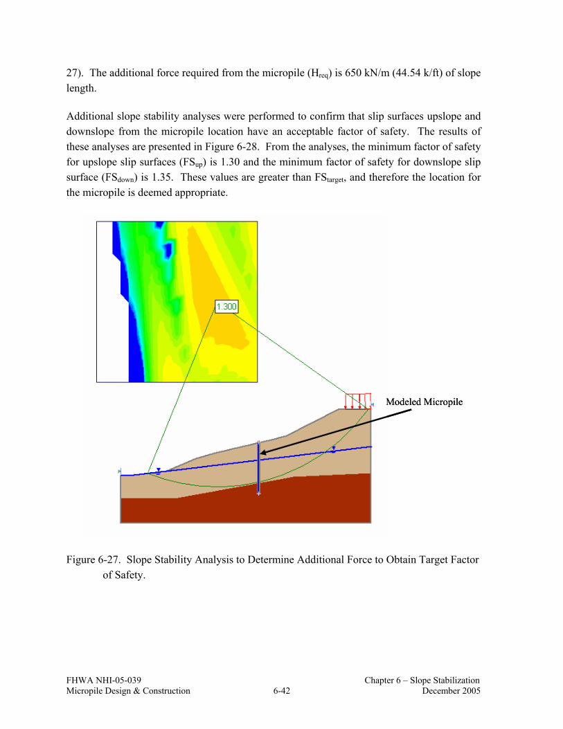
FHWA NHI-05-039 Chapter 6 – Slope Stabilization Micropile Design & Construction 6-42 December 2005
27). The additional force required from the micropile (Hreq) is 650 kN/m (44.54 k/ft) of slope length.
Additional slope stability analyses were performed to confirm that slip surfaces upslope and downslope from the micropile location have an acceptable factor of safety. The results of these analyses are presented in Figure 6-28. From the analyses, the minimum factor of safety for upslope slip surfaces (FSup) is 1.30 and the minimum factor of safety for downslope slip surface (FSdown) is 1.35. These values are greater than FStarget, and therefore the location for the micropile is deemed appropriate.
Modeled MicropileModeled Micropile
Figure 6-27. Slope Stability Analysis to Determine Additional Force to Obtain Target Factor of Safety.

FHWA NHI-05-039 Chapter 6 – Slope Stabilization Micropile Design & Construction 6-43 December 2005
(a) (b)
Figure 6-28. Stability of the (a) Upslope Away from the Micropile and (b) Downslope Away from the Micropile.
If the factor of safety of the slope entirely downslope or entirely upslope of the micropile was less than FStarget then the location of the micropile would need to be changed or an additional micropile would be required.
6.7.3 STEP 6: Select Micropile Cross Section
In this example, the micropile cross section is selected as shown in Figure 6-29. A Type A micropile is used. The ground is considered nonagressive and no reduction in steel casing thickness is required.

FHWA NHI-05-039 Chapter 6 – Slope Stabilization Micropile Design & Construction 6-44 December 2005
API-N80 CasingO.D.casing = 177.8 mm Wall Thickness = 11.50 mmFy = 552,000 kPa
Grout (fc’ = 27.6 MPa)
0.22
9 m
(MIN
.) D
rill H
ole
API-N80 CasingO.D.casing = 177.8 mm Wall Thickness = 11.50 mmFy = 552,000 kPa
Grout (fc’ = 27.6 MPa)
0.22
9 m
(MIN
.) D
rill H
ole
Note: 1 mm = 0.04 in, 1 m = 3.281 ft, 1 MPa = 1,000 kPa = 145.1 psi
Figure 6-29. Micropile Cross-Section for the Design Example.
6.7.4 STEP 7: Estimate Length Of Micropile
Estimate total length (Ltotal) of the micropile as:
Ltotal = Labove + Lbelow (Eq. 6-15)
Labove is the length of micropile between the ground surface and the critical slip surface. Lbelow is the length of the micropile below the critical slip surface.
In the design example, Labove is approximately 10 m (3.28 ft). This depth can be approximated from Figure 6-24 based on the selected micropile location shown in Figure 6-27. To calculate Lbelow, Pult is calculated using Eq. 6-1:
k) (107 kN 475 m 0.229 m 10 kPa 66d L P aboveabove-bondult =×××=×××= ππα

FHWA NHI-05-039 Chapter 6 – Slope Stabilization Micropile Design & Construction 6-45 December 2005
The value for αbond-above is within the range for Type A micropiles in relatively stiff silts and clays (see Table 5-3).
Lbelow is calculated as:
ft) (8.5 m 2.6 2.0 m 0.229 kPa 515
kN 475 FS PL below-bond
ultbelow =×
××=×
××=
ππα d
where αbond-below is estimated from Table 5-3 for hard shale. The bedrock at the site consists of siltstone, which is by definition closer to shale than sandstone or limestone. The FS for ultimate side resistance was selected to be 2.0.
The estimated length to resist uplift or compression forces is calculated to be 2.6 m. Preliminary LPILE analyses showed that this length of micropile below the slip surface was not sufficient to provide fixity of the micropile. To promote fixity of the micropile below the critical slip surface (with respect to lateral loading considerations), the length of the micropile below the critical slip surface was increased from 2.6 m (8.5 ft) to 4.5 m (15 ft) based on further analysis.
6.7.5 STEP 8: Evaluate Bending Capacity Of Single Vertical Micropile
The ultimate bending moment, Mult, for a single vertical micropile with the cross section shown in Figure 6-29 is evaluated in this step using LPILE. The single vertical micropile model is shown in Figure 6-30. In addition to the cross section geometry, the following material properties must be specified for the analysis: (1) grout compressive strength; (2) yield strength of the steel casing; and (3) modulus of elasticity of the steel.
The soil parameters for the LPILE analysis are shown in Figure 6-30. For this lateral loading condition, the profile at the location of the micropile was modeled using p-y curves for stiff clays. The undrained strength, Su, was conservatively estimated for the fill and residual soil layer based on measured SPT N values. Modeling the bedrock as a stiff clay is also conservative. More accurate parameter values could have been evaluated by more sophisticated testing methods.
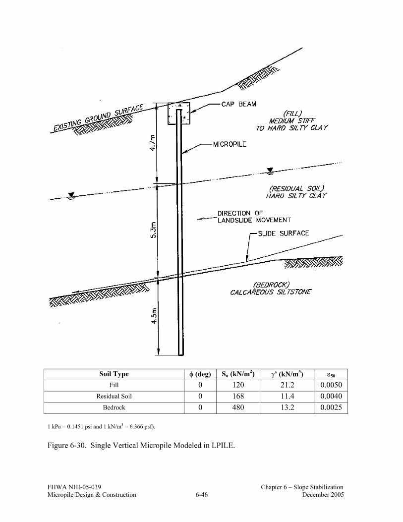
FHWA NHI-05-039 Chapter 6 – Slope Stabilization Micropile Design & Construction 6-46 December 2005
Soil Type φ (deg) Su (kN/m2) γ’ (kN/m3) ε50 Fill 0 120 21.2 0.0050
Residual Soil 0 168 11.4 0.0040 Bedrock 0 480 13.2 0.0025
1 kPa = 0.1451 psi and 1 kN/m3 = 6.366 psf).
Figure 6-30. Single Vertical Micropile Modeled in LPILE.

FHWA NHI-05-039 Chapter 6 – Slope Stabilization Micropile Design & Construction 6-47 December 2005
In the analysis, Mult is calculated for P = 0 and for P = Pult = 475 kN (107 k). The value for Mult was calculated using the option within LPILE to account for nonlinear flexural rigidity of the micropile. That is, the bending stiffness of the micropile reduces with increasing strain. The value for Mult is assumed to correspond to the bending moment in the micropile for which the compressive strain in the grout inside the casing is 0.003. The results of the Mult evaluation are shown in Table 6-2.
Table 6-2. Mult Values for Design Example.
P Mult (kN) (k) (kN.m) (k.ft)
0 0 161.3 119.0 475 107 147.7 108.9
6.7.6 STEP 9: Evaluate Shear Capacity of Single Vertical Micropile
The maximum shear capacity of a single vertical micropile (Q) is determined iteratively by performing laterally loaded pile analyses. For the design example, p-y curves may be generated within LPILE in the same analyses as were performed for the calculation of Mult. The p-y curves are generated for various depths along the micropile and specifically for depths just below and above the depth of the transition between individual soil or rock layers (Figure 6-30). The depths chosen for this example are shown in Figure 6-31.
After obtaining the p-y curves, the maximum shear capacity of a single vertical micropile can be calculated using: (1) Mult from P = 0 case; and (2) Mult from P = Pult case using up and down analyses.
The iterative design process for up and down analyses is summarized in Figure 6-32. Perform a set of up and down analyses for P = 0 axial load case first and then perform the same analyses for P = Pult following the process described below:
1. Set up the up and down analyses by inputting micropile cross section, micropile material properties, soil or rock parameters for each layer and p-y curves (adjust the location of p-y curves relative to slip surface as shown on Figure 6-17).
2. Input a trial estimate of the shear force Q (magnitude and signs are same for up analysis and down analysis) and input a trial estimate of the internal bending moment (M) (magnitude is same but M is negative for the up analysis and positive for the down analysis). It should be noted that the selection of trial

FHWA NHI-05-039 Chapter 6 – Slope Stabilization Micropile Design & Construction 6-48 December 2005
estimates for Q and M are arbitrary. If the initial estimate of Q is less than the value of Q which ultimately corresponds to Mult, the solution will converge. If the initial estimate of Q is greater than the value of Q which ultimately corresponds to Mult, the solution will not converge. This will be evidenced by pile head slopes from the up and down analysis which diverge from each other with each iteration.
3. Perform laterally loaded pile analyses for up and down analyses and compare the slopes computed at the micropile head from both analyses. If the slopes at the micropile head are not equal then change the magnitude of the initially estimated M (i.e., in Step 1) and re-run both analyses again. When slopes at the pile head are equal from both analyses, note the calculated maximum bending moment (Mmax) from each analysis.
4. Compare Mmax (greater of Mmax values from up and down analyses) with previously calculated bending moment capacity (Mult) for the corresponding axial load.
5. If Mmax is approximately equal to Mult then Q is determined and analysis for this axial load case is completed. If Mmax is not equal to Mult, change the magnitude of the initially estimated Q (i.e., in Step 5) and re-run both analyses again.
6. Repeat steps 1 through 4 for the P = Pult case. In step 3 use Mult calculated for the P = Pult case.
Note: 1 m = 3.281 ft.
Figure 6-31. Depths Chosen for p-y Curves for Entire Length of the Micropile.

FHWA NHI-05-039 Chapter 6 – Slope Stabilization Micropile Design & Construction 6-49 December 2005
Compare pile head slopes from
up and down analyses
Compare pile head slopes from
up and down analyses
If pile head slopes from both analyses are equal
Compare Mmax(1) with Mult
If pile head slopes from both analyses are equal
Compare Mmax(1) with Mult
If pile head slopes from both analyses are not equal
Change M and re-run up and down analyses
If pile head slopes from both analyses are not equal
Change M and re-run up and down analyses
If Mmax equals Mult
Q is obtained.(Analysis is complete)
If Mmax equals Mult
Q is obtained.(Analysis is complete)
If Mmax is not equal to Mult
Change Q in both analyses and re-run up and down analyses
If Mmax is not equal to Mult
Change Q in both analyses and re-run up and down analyses
Laterally Loaded Pile AnalysesTo
Evaluate Shear Capacity of Micropiles
Laterally Loaded Pile AnalysesTo
Evaluate Shear Capacity of Micropiles
Input for “up analysis”p-y curvesEstimated + QEstimated – MP = 0 or P = Pult
Input for “up analysis”p-y curvesEstimated + QEstimated – MP = 0 or P = Pult
Input for “down analysis”p-y curvesEstimated + QEstimated + MP = 0 or P = Pult
Input for “down analysis”p-y curvesEstimated + QEstimated + MP = 0 or P = Pult
Output from “up analysis”Slope at the pile headMmax (up)
Output from “up analysis”Slope at the pile headMmax (up)
Output from “down analysis”Slope at the pile headMmax (down)
Output from “down analysis”Slope at the pile headMmax (down)
Note: (1) Mmax = the greater of Mmax (up) and Mmax (down)
Compare pile head slopes from
up and down analyses
Compare pile head slopes from
up and down analyses
If pile head slopes from both analyses are equal
Compare Mmax(1) with Mult
If pile head slopes from both analyses are equal
Compare Mmax(1) with Mult
If pile head slopes from both analyses are not equal
Change M and re-run up and down analyses
If pile head slopes from both analyses are not equal
Change M and re-run up and down analyses
If Mmax equals Mult
Q is obtained.(Analysis is complete)
If Mmax equals Mult
Q is obtained.(Analysis is complete)
If Mmax is not equal to Mult
Change Q in both analyses and re-run up and down analyses
If Mmax is not equal to Mult
Change Q in both analyses and re-run up and down analyses
Laterally Loaded Pile AnalysesTo
Evaluate Shear Capacity of Micropiles
Laterally Loaded Pile AnalysesTo
Evaluate Shear Capacity of Micropiles
Input for “up analysis”p-y curvesEstimated + QEstimated – MP = 0 or P = Pult
Input for “up analysis”p-y curvesEstimated + QEstimated – MP = 0 or P = Pult
Input for “down analysis”p-y curvesEstimated + QEstimated + MP = 0 or P = Pult
Input for “down analysis”p-y curvesEstimated + QEstimated + MP = 0 or P = Pult
Output from “up analysis”Slope at the pile headMmax (up)
Output from “up analysis”Slope at the pile headMmax (up)
Output from “down analysis”Slope at the pile headMmax (down)
Output from “down analysis”Slope at the pile headMmax (down)
Note: (1) Mmax = the greater of Mmax (up) and Mmax (down)
Figure 6-32. Process to Evaluate Shear Resistance (Q) of Single Vertical Micropile Using Up and Down Laterally Loaded Pile Analyses.

FHWA NHI-05-039 Chapter 6 – Slope Stabilization Micropile Design & Construction 6-50 December 2005
The laterally loaded pile analysis output for P = 0 and P = Pult are presented in Appendix B. The up analysis is performed for the pile length of 10 m (32.8 ft) and the down analysis for the pile length of 4.5 m (15 ft). The soil/rock layers in up and down analyses are modeled by adjusting the previously determined p-y curves. For each soil layer depth, p-y curves are inputted in the model. An example is shown in Figure 6-33 for the up analysis. The p-y values in the “external p-y curve” dialog box in Figure 6-33 are the previously determined p-y values at a depth of 10 m. Using the adjustment shown in Figure 6-17a, they are assigned to a depth of 0 m for the up analysis.
Figure 6-33. Modeling Soil Layers with Previously Determined p-y Curves.

FHWA NHI-05-039 Chapter 6 – Slope Stabilization Micropile Design & Construction 6-51 December 2005
For the P = 0 case, the shear capacity of the micropile (QP=0) is calculated as 365 kN (82 k) and the maximum bending moment (Mmax) is calculated as 161.3 kN.m (119.0 k.ft). The Mult for this axial load case was previously calculated as 161.3 kN.m (119.0 k.ft) (see Table 6-2).
For the P = Pult case, the shear capacity of the micropile (QP=Pult) is calculated as 330 kN (74.2 k) and the maximum bending moment is calculated as 147.7 kN.m (108.9 k.ft). The Mult for this axial load case was previously calculated as 147.7 kN.m (108.9 k.ft) (see Table 6-2).
For both axial load conditions, Mmax is approximately equal to Mult and the up/down analyses are considered to be complete. Therefore, both QP=0 and QP=Pult can be used in the subsequent design steps to evaluate the shear capacity of battered micropiles.
6.7.7 STEP 10: Evaluate Shear Capacity of Battered Micropile Group
For this step, the maximum lateral force that the battered micropile group or pair (i.e., upslope micropile leg and downslope micropile leg as shown in Figure 6-9) (Hult-pair) can resist at the location of the critical slip surface is evaluated (see Section 6.6.5).
In this design example, the batter angle for the upslope micropile leg is selected as 3o and the batter angle for the downslope micropile leg is selected as 21o. The Hult for each leg is calculated as shown below:
For ψus = 3o, Hult (ψus) = QP=0 = 365 kN (82 k)
For ψds = 21o, Hult (ψds) has to be interpolated. Hult (ψds) calculated for various batter angles are shown in Table 6-3 and interpolation for ψds =21o is shown in Figure 6-34. Hult (ψus) is evaluated as 450 kN (101 k).

FHWA NHI-05-039 Chapter 6 – Slope Stabilization Micropile Design & Construction 6-52 December 2005
Table 6-3. Hult (ψds) for Various Batter Angles.
Hult(ψds) ψds (degree) (kN) (k)
Equations
0 365 82 10 365 82
6-8
30 523 117.6 40 558 125.4
6-7
Therefore, according to Eq. 6-10:
( ) ( )ψdsultψusultpair-ult H H H += = 365 + 450 = 815 kN (183.2 k)
This is the calculated maximum lateral force that the micropile pair can resist at the location of the critical slip surface.
6.7.8 STEP 11: Calculate Spacing Required to Provide Force to Stabilize the Slope
The definition of spacing between two upslope micropiles and two downslope micropiles is presented in Figure 6-22 and is calculated using Eq. 6-11 as:
req
pair-ultmax H
H S =
In the design example, Hreq is calculated as 650 kN/m (44.5 k/ft) and Hult-pair is calculated as 815 kN (183.2 k), therefore Smax is:
m 25.1 kN/m650kN 815 Smax ==
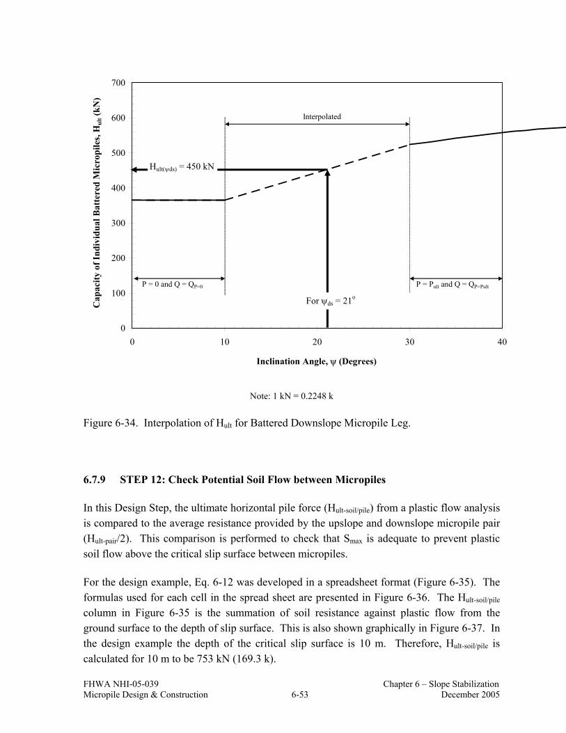
FHWA NHI-05-039 Chapter 6 – Slope Stabilization Micropile Design & Construction 6-53 December 2005
0
100
200
300
400
500
600
700
0 10 20 30 40
Inclination Angle, ψ (Degrees)
Cap
acity
of I
ndiv
idua
l Bat
tere
d M
icro
pile
s, H
ult (
kN)
P = 0 and Q = QP=0 P = Pult and Q = QP=Pult
Interpolated
For ψds = 21o
Hult(ψds) = 450 kN
Note: 1 kN = 0.2248 k
Figure 6-34. Interpolation of Hult for Battered Downslope Micropile Leg.
6.7.9 STEP 12: Check Potential Soil Flow between Micropiles
In this Design Step, the ultimate horizontal pile force (Hult-soil/pile) from a plastic flow analysis is compared to the average resistance provided by the upslope and downslope micropile pair (Hult-pair/2). This comparison is performed to check that Smax is adequate to prevent plastic soil flow above the critical slip surface between micropiles.
For the design example, Eq. 6-12 was developed in a spreadsheet format (Figure 6-35). The formulas used for each cell in the spread sheet are presented in Figure 6-36. The Hult-soil/pile column in Figure 6-35 is the summation of soil resistance against plastic flow from the ground surface to the depth of slip surface. This is also shown graphically in Figure 6-37. In the design example the depth of the critical slip surface is 10 m. Therefore, Hult-soil/pile is calculated for 10 m to be 753 kN (169.3 k).

FHWA NHI-05-039 Chapter 6 – Slope Stabilization Micropile Design & Construction 6-54 December 2005
For this design, Hult-soil/pile = 753 kN (169.3 k) ≥ Hult-pair/2 = 407.5 kN (91.6 k). Therefore, plastic flow conditions are satisfied and the calculated Smax from Design Step 11 does not need to be reduced.
6.7.10 STEP 13: Perform Structural Design of Concrete Cap Beam
The steel-reinforced CIP concrete cap beam spans and anchors the micropile array at the ground surface. The concrete cap beam is typically 2-m wide and 1-m deep, but, in general, the cap beam should have sufficient height and width to allow for at least two to three micropile diameters embedment into the cap beam to promote fixity of the upslope and downslope micropile. The structural design of the concrete cap beam follows typical methods for reinforced concrete (see Section 8 of AASHTO (2002)). Specific considerations involved in the design of a concrete cap beam include:
• Where ground anchors are used, the cap beam provides a reaction for the ground anchors to be installed and subsequently stressed and locked-off. The cap beam needs to be designed for these forces.
• Where ground anchors are not incorporated, axial loads transferred towards the ground surface should be small (particularly if the slide plane is relatively deep). Although these forces are postulated to be small, the provision of fixity of the micropile group at the cap beam will cause load transfer to the cap beam. Also, where the depth of the slide plane is relatively shallow, it is likely that bending moments in the cap beam may be on the order of bending moments calculated at the slide plane. For this case, soil-structure interaction analyses should be performed to evaluate bending moments for structural design of the cap beam.
• In some cases, relatively significant deflections of the cap beam may need to be considered in the structural design. That is, ground anchor stressing, non-uniform depth to competent material, and/or compression of soil material within the unstable soil mass may result in differential settlements of the length of the cap beam. The resulting bending stresses and torsional stresses from such movements should be considered in the structural design of the cap beam.

FHWA NHI-05-039 Chapter 6 – Slope Stabilization Micropile Design & Construction 6-55 December 2005
Note:Deifinitions of the parameters used in this spread sheet can be found in Equations 6-11 and 6-12 and Figure 6-23
Input Parameters
Smax from Design Step 11 = 1.25 m
c = 168 kPaγ = 21.2 kN/m3
φ = 0.01 degrees (Note: for φ = 0 conditions input very small value for φ)b = 0.1778 m
Calculations
D2 = 1.07 m Nφ = 1.00E+00 (dim)π = 3.1415927 A = 1.25E+00
tan φ = 1.75E-04 B = 1.00E+00 φ/4 = 4.36E-05 E = 1.75E-04π/8 = 3.93E-01 F = 5.73E+03
tan(φ/4+π/8) = 4.14E-01Nφ tan φ = 1.75E-04
z (m) Total Resistance (kPa) Hult-soil/pile (kN/m)0 51 511 55 1052 59 1623 63 2224 66 2875 70 3556 74 4277 78 5038 82 5839 85 66610 89 75311 93 84412 97 93913 100 103714 104 114015 108 124620 127 1832
Figure 6-35. Spreadsheet Calculations Based on Eq. 6-12 to Obtain Hult-soil/pile for the Example Problem.

FHW
A N
HI-
05-0
39
C
hapt
er 6
– S
lope
Sta
biliz
atio
n M
icro
pile
Des
ign
& C
onst
ruct
ion
6-56
D
ecem
ber 2
005
1 2 3 4 5 6 7 8 9 10 11 12 13 14 15 16 17 18 19 20 21 22 23 24 25 26 27 28 29 30 31 32 33 34 35 36 37 38 39 40
AB
Inpu
t Par
amet
ers
S max
from
Des
ign
Step
11
=1.
25
c =
168
γ =
21.2
φ =
0.01
b =
0.17
78
Cal
cula
tions
D2
==$
B$4
-$B
$9π
==P
I()ta
n φ
==T
AN(R
ADIA
NS(
$B$8
)) φ
/4 =
=RA
DIA
NS
(B$8
/4)
π/8
==$
B$1
5/8
tan(
φ/4+
π/8)
==T
AN($
B$17
+$B
$18)
Nφ ta
n φ
==$
B$2
2*$B
$16
Nφ
==T
AN(($
B$1
5/4)
+(R
AD
IAN
S($
B$8/
2)))
^2A
==(
$B$4
)*($
B$4
/$B
$14)
^(($
B$2
2^0.
5*$B
$16+
$B$2
2-1)
)B
==E
XP
((($
B$4
-$B$
14)/$
B$1
4)*$
B$2
0*$B
$19)
E =
=($B
$22^
0.5)
*$B
$16
F =
=((2
*$B
$16)
+(2*
($B
$22^
0.5)
)+($
B$22
^-0.
5))/(
$B$2
5+$B
$22-
1)
z (m
)To
tal R
esis
tanc
e (k
Pa)
0=(
($B$
23*$
B$6*
((1/
($B$
22*$
B$16
))*(
$B$2
4-(2
*$B$
25)-
1)+$
B$26
)))-
$B$6
*($B
$4*$
B$26
-2*$
B$14
*$B$
22^-
0.5)
+(((
$B$7
*A29
)/$B$
22)*
($B$
23*$
B$2
4-$B
$14)
)5
=(($
B$23
*$B$
6*((
1/($
B$22
*$B$
16))
*($B
$24-
(2*$
B$25
)-1)
+$B$
26))
)-$B
$6*(
$B$4
*$B$
26-2
*$B$
14*$
B$22
^-0.
5)+(
(($B
$7*A
30)/$
B$22
)*($
B$23
*$B
$24-
$B$1
4))
10=(
($B$
23*$
B$6*
((1/
($B$
22*$
B$16
))*(
$B$2
4-(2
*$B$
25)-
1)+$
B$26
)))-
$B$6
*($B
$4*$
B$26
-2*$
B$14
*$B$
22^-
0.5)
+(((
$B$7
*A31
)/$B$
22)*
($B$
23*$
B$2
4-$B
$14)
)15
=(($
B$23
*$B$
6*((
1/($
B$22
*$B$
16))
*($B
$24-
(2*$
B$25
)-1)
+$B$
26))
)-$B
$6*(
$B$4
*$B$
26-2
*$B$
14*$
B$22
^-0.
5)+(
(($B
$7*A
32)/$
B$22
)*($
B$23
*$B
$24-
$B$1
4))
20=(
($B$
23*$
B$6*
((1/
($B$
22*$
B$16
))*(
$B$2
4-(2
*$B$
25)-
1)+$
B$26
)))-
$B$6
*($B
$4*$
B$26
-2*$
B$14
*$B$
22^-
0.5)
+(((
$B$7
*A33
)/$B$
22)*
($B$
23*$
B$2
4-$B
$14)
)
z (m
)H
ult-s
oil/p
ile (k
N/m
)0
=B29
5=B
36+0
.5*(
A30
-A29
)*(B
30+B
29)
10=B
37+0
.5*(
A31
-A30
)*(B
31+B
30)
15=B
38+0
.5*(
A32
-A31
)*(B
32+B
31)
20=B
39+0
.5*(
A33
-A32
)*(B
33+B
32)
Figu
re 6
-36.
Equ
atio
ns U
sed
in E
ach
Cel
l in
Figu
re 6
-35.
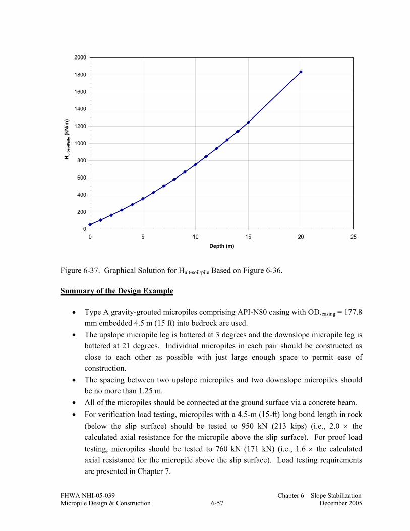
FHWA NHI-05-039 Chapter 6 – Slope Stabilization Micropile Design & Construction 6-57 December 2005
0
200
400
600
800
1000
1200
1400
1600
1800
2000
0 5 10 15 20 25
Depth (m)
Hul
t-soi
l/pile
(kN
/m)
Figure 6-37. Graphical Solution for Hult-soil/pile Based on Figure 6-36.
Summary of the Design Example
• Type A gravity-grouted micropiles comprising API-N80 casing with OD.casing = 177.8 mm embedded 4.5 m (15 ft) into bedrock are used.
• The upslope micropile leg is battered at 3 degrees and the downslope micropile leg is battered at 21 degrees. Individual micropiles in each pair should be constructed as close to each other as possible with just large enough space to permit ease of construction.
• The spacing between two upslope micropiles and two downslope micropiles should be no more than 1.25 m.
• All of the micropiles should be connected at the ground surface via a concrete beam. • For verification load testing, micropiles with a 4.5-m (15-ft) long bond length in rock
(below the slip surface) should be tested to 950 kN (213 kips) (i.e., 2.0 × the calculated axial resistance for the micropile above the slip surface). For proof load testing, micropiles should be tested to 760 kN (171 kN) (i.e., 1.6 × the calculated axial resistance for the micropile above the slip surface). Load testing requirements are presented in Chapter 7.

FHWA NHI-05-039 Chapter 6 – Slope Stabilization Micropile Design & Construction 6-58 December 2005
6.8 SHEAR CAPACITY OF MICROPILES FOR ANALYSIS
As previously noted, the shear load that an individual micropile provides is assumed to correspond to the maximum shear force in the micropile when the micropile has reached its ultimate bending capacity. The rationale for this is explained below.
A slope that has failed (i.e., some movement has been observed and may have stopped or continuous or intermittent movements being measured) implies that its slope stability factor of safety is equal to 1.0. Since the design of the micropile-stabilized slope is predicated on good knowledge of the position of the failure surface and the pore pressures in the slope at the time of failure, then the loads and soil resistances are reasonably well-known, and, in fact, are equal in magnitude to each other (i.e., the FS = 1.0 condition requires this).
The analysis now requires that the slope be stabilized to a target factor of safety (e.g., FS = 1.3). Using the shear strengths obtained from the back-analysis of a failed slope, a shear force (provided by the micropile) is added until the target factor of safety for the slope is calculated. It is recommended that this shear force be added to the resisting forces (or moments) in the limit equilibrium calculations (as compared to treating it as a negative driving force or moment).
In an allowable stress design format, the service loads on the micropile are equal to zero since the slope is “stable” at a FS of 1.0. In a retaining wall, for example, the service loads on the wall for the FS = 1.0 condition are not zero and may be associated with full active earth pressure conditions.
To increase the factor of safety of the slope, micropiles are added. In the design, it is assumed that, if the ultimate shear capacity of the micropiles was mobilized at a limit (i.e., failure) state, the factor of safety of the slope would be at 1.3. This approach is exactly consistent with reinforced slope design. In that case, the design strength of the reinforcement corresponds to its strength at a specific design life, Tal and then slope stability analyses are performed to verify a target factor of safety for the slope. As for the micropile analysis described herein, no reductions to some allowable stress (or strength) are used. Whereas, the reinforced slope soil reinforcement strength is reduced to account for creep, durability, and construction damage, the strength of the micropile may be reduced to account for potential steel loss due to corrosion.
A design engineer may incorporate additional conservatism in a project if warranted. For example, additional conservatism may be prudent if the failure slip surface and/or residual soil shear strength are not well understood for a particular slide or if the soil within the failure slip surface has the potential for continued long-term creep movements. Additional

FHWA NHI-05-039 Chapter 6 – Slope Stabilization Micropile Design & Construction 6-59 December 2005
conservatism may be incorporated through selection of soil properties, phreatic surface assumptions, value of target slope stability factor of safety, maximum micropile shear force, or a combination of these. Note that a probabilistic analysis can be performed to examine slope stability factor of safety values for ranges of material parameters (see Duncan et al., 1999), and that this can provide a better understanding of the effect of material parameters.
6.9 CASE HISTORIES
6.9.1 Stabilization of Blue Trail Landslide Using Micropiles, Wyoming
The Blue Trail Landslide project is located on U.S. Highway 26/89 between Alpine Junction and Hoback Junction, Wyoming. This section of roadway is next to the canyon of the Snake River (Figure 6-38). This highway was constructed between 1955 and 1960 and had experienced episodes of movement resulting from movement of the landslide. Throughout the years, various remedial design alternatives were reviewed to mitigate slope movements and to stabilize the slide to a desired factor of safety of 1.3. Alternatives considered included regrading the slope and constructing a toe berm, constructing a bridge over the entire slide area, and installing drilled shafts near the toe of the landslide to provide structural restraint (Hasenkamp, 1999). These alternatives were rejected for implementation because they were not cost effective. Ultimately, micropiles were selected for implementation since they were less expensive that other alternatives and could be constructed in highly variable ground and under restricted access conditions. Other advantages included the ability to maintain traffic during construction and minimal environmental impacts.
The design of the micropiles was performed using the design approach described in this chapter. Originally, two micropile walls (i.e., two sets of upslope and downslope micropiles) and a mechanically stabilized earth (MSE) wall were designed to stabilize the slope (Figure 6-39). The first wall was located 3 m below the roadway (i.e., upper wall) and the second one was located approximately between the road and the toe of the slide (i.e., lower wall). At a later time, a third wall was added along the western edge of the project at about 12 m (39 ft) below the roadway to increase the factor of safety of the slope at that location. The original design included a single ground anchor at each wall location. During the early stages of construction, it became necessary to significantly increase the restraining force provided by the lower wall. This was the result of a significant increase in the seismic coefficient that was required by a reviewing agency. This was accomplished by significantly increasing the capacity of the ground anchors in the lower wall. Micropiles were battered 30 degrees from the vertical and ranged in length from 19 to 34 m (62 to 112 ft). Ground anchors were installed at 30 degrees from the horizontal (see Figure 6-40).

FHWA NHI-05-039 Chapter 6 – Slope Stabilization Micropile Design & Construction 6-60 December 2005
Figure 6-38. Extent of Blue Trail Landslide (after Hasenkamp, 1999).
Figure 6-39. Conceptual Design Drawing of the MSE and NRM Walls for Blue Trail Landslide Project (after Hasenkamp, 1999).
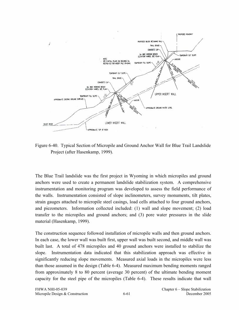
FHWA NHI-05-039 Chapter 6 – Slope Stabilization Micropile Design & Construction 6-61 December 2005
Figure 6-40. Typical Section of Micropile and Ground Anchor Wall for Blue Trail Landslide Project (after Hasenkamp, 1999).
The Blue Trail landslide was the first project in Wyoming in which micropiles and ground anchors were used to create a permanent landslide stabilization system. A comprehensive instrumentation and monitoring program was developed to assess the field performance of the walls. Instrumentation consisted of slope inclinometers, survey monuments, tilt plates, strain gauges attached to micropile steel casings, load cells attached to four ground anchors, and piezometers. Information collected included: (1) wall and slope movement; (2) load transfer to the micropiles and ground anchors; and (3) pore water pressures in the slide material (Hasenkamp, 1999).
The construction sequence followed installation of micropile walls and then ground anchors. In each case, the lower wall was built first, upper wall was built second, and middle wall was built last. A total of 478 micropiles and 40 ground anchors were installed to stabilize the slope. Instrumentation data indicated that this stabilization approach was effective in significantly reducing slope movements. Measured axial loads in the micropiles were less than those assumed in the design (Table 6-4). Measured maximum bending moments ranged from approximately 8 to 80 percent (average 30 percent) of the ultimate bending moment capacity for the steel pipe of the micropiles (Table 6-4). These results indicate that wall

FHWA NHI-05-039 Chapter 6 – Slope Stabilization Micropile Design & Construction 6-62 December 2005
performance was acceptable. The direction of axial load and bending moments in the micropiles of the lower wall was opposite to that assumed in the design. This resulted from the significant lock-off loads within the lower wall ground anchors. Micropiles in the upper wall showed compression for both the upslope and downslope directions. This is most likely the result of surcharge load associated with placement of the MSE wall and roadway over the upper insert wall.
Table 6-4. Comparison of Actual Loads to Design Loads for Blue Trail Landslide Project (after Hasenkamp, 1999).
Wall Micropile Number
Micropile Orientation
L (m) PDesign (kN)(1)
PMeasured (kN)(1)
Mult-Design
(kN-m) Mult-Measured
(kN-m)
62 Upslope 23.8 635 -686 35.2 15.4
63 Downslope 33.5 -894 -566 35.2 3.3
123 Downslope 27.7 -739 153 35.2 4.0 Upper
124 Upslope 23.8 635 -302 35.2 14.6
326 Downslope 19.2 -717 214 35.2 8.5
327 Upslope 19.5 728 -594 35.2 2.9
402 Downslope 19.5 -728 398 35.2 3.2 Lower
403 Upslope 19.5 728 -450 35.2 3.8
Notes: (1) Negative values indicate compression. L: Length of the micropile. PDesign and PMeasured: Design axial load and axial load measured in the field, respectively.
Mult-Design and Mult-Measured: Ultimate bending moment of micropile section and bending moment measured in the field, respectively.
6.9.2 Stabilization of Sum-271 Landslide Using Micropiles, Ohio
The SUM-271 project is located on Interstate 271 northbound in Richfield Township, Summit County, Ohio. The site consists of approximately 21 m (70 ft) of valley fill overlying relatively thin and weak layers of normally consolidated fine grained lacustrine soils with strong overconsolidated lacustrine soils beneath. Over the years, slope movements resulted in pavement settlement and cracking. Two alternatives were considered for stabilization. One alternative consisted of regrading the slope and constructing toe buttress berms and the other alternative included using micropiles (Liang, 2000). The Ohio Department of Transportation (ODOT) selected the micropile option.

FHWA NHI-05-039 Chapter 6 – Slope Stabilization Micropile Design & Construction 6-63 December 2005
The design of the micropiles was performed using the design approach presented in this chapter. Because micropiles were not able to completely develop the resisting forces required, ground anchors were added to the design. The wall consisted of 154 type A micropiles that were spaced 1.2- to 1.8-m (4- to 6-ft) apart and battered 30 degrees from the vertical and 41 ground anchors that were spaced 3.5 m (12 ft) apart and battered 30 degrees from the horizontal (Figure 6-41).
Figure 6-41. Typical Section of Micropile and Ground Anchor Wall at SUM-271 (after Liang, 2000).
A comprehensive instrumentation and monitoring program for the wall was developed for this project. Inclinometers were installed in the slope to monitor slope movement and strain gauges were attached to the micropiles to allow for measurements of axial loads and bending moments in the micropiles throughout construction. High capacity load cells were used to monitor ground anchor loads. Inclinometer data indicated that the installation of the NRM wall and ground anchors was effective in arresting the slope movement.
As part of this project, detailed finite element analyses were performed to model the wall behavior (Liang, 2000). These analyses simulated relevant stages of construction including earthwork, pile cap construction, drilling, and installation of micropiles and stressing of the ground anchors. Finite element analysis results were compared to field instrumentation monitoring data to validate the capability of the FEM modeling technique and to provide supplemental information. Based on the finite element analysis results and field

FHWA NHI-05-039 Chapter 6 – Slope Stabilization Micropile Design & Construction 6-64 December 2005
measurements of wall performance, the following observations and conclusions were developed:
1. The maximum axial force in each micropile occurred at the location near the slip surface of the slope (i.e., approximately 30 ft below the ground surface) (Figure 6-42). The direction and magnitude of the axial forces in the micropiles were consistent with loading conditions resulting from the various stages of construction. For example, the upslope micropile was initially in tension (following installation). When the ground anchor was tensioned, a portion near the top of the upslope micropile remained in tension, while the remaining portion of the wall was in compression. The axial forces in the downslope micropile were initially in compression but after the ground anchor tensioning, the compressive forces were reduced. However, no tension was developed in the downslope micropile.
Figure 6-42. Comparison of Axial Loads for the SUM-271 Project (after Liang, 2000).

FHWA NHI-05-039 Chapter 6 – Slope Stabilization Micropile Design & Construction 6-65 December 2005
2. The bending moments were near zero at the location where the maximum axial forces occurred (Figure 6-43). The change in bending moments throughout the construction stages were small and were primarily due to small stiffness of the micropiles. The magnitude of the maximum bending moments was reasonably predicted by the finite element analyses.
Figure 6-43. Comparison of Bending Moments for the SUM-271 Project (after Liang, 2000).

FHWA NHI-05-039 Chapter 6 – Slope Stabilization Micropile Design & Construction 6-66 December 2005
6.9.3 Stabilization of Littleville Landslide using Micropiles, Alabama
The Littleville landslide is located on a section of US Route 43, Alabama. The area of the landslide is a fill composed of sandstone and shale cut from adjacent hillsides. The underlying stratum is shale with some weathering along the top surface, which is believed to be the failure surface. A highway was constructed at the site in the 1950s. Soon after construction of the original roadway was finished, stability problems arose and the road surface dropped due to slides in the fill material. Initially the holes were filled and the road was repaved. In the 1970s, the roadway was widened and the slope was flattened. However, ensuing rainy periods brought on the onset of more slope failures. The creep of the slope continued until a micropile wall with additional stabilization provided by ground anchors was built in 1997 to stabilize the slope (Brown and Chancellor, 1997).
The design of micropile wall was performed following the same approach as is described in this chapter. A typical cross section of the slide and the reinforcement installed at the site are provided in Figure 6-44. The micropiles included 114-mm (4.5 in.) diameter steel casing with a wall thickness of 8 mm. Micropile design lengths were 7 m (23 ft) and were battered 30 degrees from vertical. A total of 432 micropiles and 44 ground anchors were installed for the project.
Figure 6-44. Typical Section of Micropile and Anchor Wall at Littleville, Alabama (after Brown and Chancellor, 1997).

FHWA NHI-05-039 Chapter 6 – Slope Stabilization Micropile Design & Construction 6-67 December 2005
Instrumentation data was collected for a period of two years. Data collected included inclinometer measurements of slope movement, pore water pressures, and stresses developed in the micropiles and anchors. Piezometers have shown relatively stable water levels over the two years with a fluctuation of approximately two or three feet.
Inclinometer data indicated that slope movement had effectively ceased as a result of the slope stabilization measure. Analysis of the strain gauge data indicated that this was accomplished without approaching potential failure conditions in the micropiles. The axial forces mobilized in the micropiles were found to be below the estimated ultimate axial load by a factor of approximately two, and the factor of safety was calculated to be approximately 1.3 as originally estimated. In addition, it was found that the upslope battered micropiles were in tension in the vicinity of the slide plane and the downslope battered piles were in compression. The strain gauges also indicated higher bending moments developed in the micropiles in the vicinity of the slide surface. Measured maximum bending moments ranged from approximately 5 to 9 percent of the ultimate bending moment capacity of the micropiles. Loads in the ground anchors were observed to decrease slightly over time and this was attributed to small movements that have occurred in the uphill direction.
6.10 REFERENCES
Brown, D.A. and Chancellor, K. (1997), “Instrumentation, Monitoring and Analysis of the Performance of a Type-A INSERT Wall, Littleville, Alabama”, Highway Research Center, Auburn, University Alabama.
Duncan, M.J., Navin, M. and Patterson, K., Manual for Geotechnical Engineering Calculations, Virginia Tech Center for Geotechnical Practice and Research, December, 1999.
Hasenkamp, R. N., (1999), “Evaluation of a Micropile Reinforced Earth Retaining Structure, Blue Trail Landslide, Wyoming”, Master Thesis, Department of Civil and Agricultural Engineering, University of Wyoming.
Hassiotis, S., Chameau, J. L., and Gunaratne, M., (1997), “Design Method for Stabilization of Slopes with Piles”, Journal of Geotechnical and Geoenvironmental Engineering, Vol. 123, No. 4, 314-323 pp.
Ito, T., and Matsui, T., (1975), “Methods to Estimate Lateral Force Acting on Stabilizing Piles”, Soil and Foundations, Vol. 15, No. 4.

FHWA NHI-05-039 Chapter 6 – Slope Stabilization Micropile Design & Construction 6-68 December 2005
Kavazanjian, E. Jr., Matasovic, N., Hadj-Hamou, T., Sabatini, P. J. (1997), Design Guidance: Geotechnical Earthquake Engineering for Highways, Geotechnical Engineering Circular, No.3, Federal Highway Administration Publication, U.S. Department of Transportation, FHWA-SA-97-077.
Liang, R.Y. (2000), “Instrumentation and Monitoring of Reticulated Micropile Slope Stabilization at SUM-271 Project,” submitted to the Federal Highway Administration, September 2000.
Mayne, P. W., Christopher, B. R., and DeJong, J. (2001), Manual on Subsurface Investigations, National Highway Institute, Publication Number NHI-01-031, Federal Highway Administration, Washington, D.C.
O’Neil, M. W. and Reese, L. C. (1999), “Drilled Shafts: Construction and Procedures and Design Methods”, Federal Highway Administration Publication, Publication Number: FHWA-IF-99-025.
Poulos, H. G. and Davis, E. H., (1980), Pile Foundation Analysis and Design, John Wiley and Sons, 397 pages.
Reese, L. C., Wang, S. T., Isenhower, W. M., Arréllaga, J. A., and Hendrix, J., (2005), “A Program for Analysis of Single Piles Under lateral Load”, Version 5.0.18, Ensoft Inc., Austin, TX.
Sabatini, P. J., Bachus, R. C., Mayne, P. W., Schneider, J. A., and Zettler, T. E. (2002). “Evaluation of Soil and Rock Properties”, Geotechnical Engineering Circular, No. 5, Federal Highway Administration, U.S. Department of Transportation, FHWA-IF-02-034.
SLIDE (2004), “Slope Stability Analyses Program”, Rocscience Inc., Ontario, Canada.
Stark and Eid, (1994) “Drained Residual Strength of Cohesive Soils”, Journal of Geotechnical Engineering, Vol. 120, No. 5.

FHWA NHI-05-039 Chapter 7 – Load Testing Micropile Design & Construction 7-1 December 2005
CHAPTER 7 MICROPILE LOAD TESTING
7.1 INTRODUCTION
On micropile foundation support projects and slope stabilization projects, “verification” load testing is performed on pre-production micropiles. The purpose of the pre-production testing is to verify design assumptions concerning bond zone strength and the adequacy of the contractor’s installation methods. This testing is usually performed as the first order of work under the construction contract. Production micropiles are approved only after the design assumptions and the adequacy of the contractor’s installation method have been verified. On large projects, additional load testing may be performed during the design stage under a separate contract.
The ability of the micropile to safely carry the design load in service is obtained through “proof” load testing on selected production micropiles. This proof testing provides a quality assurance means to confirm micropile installation procedures.
Micropiles are tested individually using the same conventional static load testing procedures as are used for driven piles and drilled shafts. These tests include incremental loading (which may be applied in compression, tension, or laterally and which may be cycled (i.e., load/unload)) until the micropile reaches the selected maximum test load, structural displacement limit, or ground creep (i.e., movement under constant load) threshold.
In this chapter, descriptions of “verification” and “proof” tests for micropiles are provided with information on typical testing equipment, schedule for load increments, and analysis of load-deformation data as a means to judge micropile acceptance for payment purposes.
7.2 OVERVIEW OF MICROPILE LOAD TESTING
Micropiles are load tested in the field to verify that the required design loads can be carried without excessive movement and with an adequate factor of safety for the life of the structure. Load testing is also used to verify the adequacy of the contractor’s drilling, installation and grouting operations prior to (verification testing) and during (proof testing) construction of production micropiles. Therefore, the ground conditions, as well as the method, equipment, and operator used for installing production piles must be similar to those

FHWA NHI-05-039 Chapter 7 – Load Testing Micropile Design & Construction 7-2 December 2005
used for installing the test micropiles. If ground and/or installation procedures change from that used from the verification load testing program, additional testing should be required. If test results indicate faulty construction practice, or grout-to-ground load capacities less than required, the contractor may be required to modify the micropile installation methods. In the event that the required design grout-to-ground bond capacities are still not achievable, redesign may be necessary.
Load testing criteria will be included in the construction specifications and will typically include ultimate and/or verification tests. These tests usually require loading to a maximum test load that includes the factor of safety assigned to the design grout-to-ground bond (i.e., the verification test) and/or that which results in failure defined as the inability to maintain constant test load without excessive micropile movement (i.e., the ultimate test). The ultimate tests, taken to failure, are usually only specified as part of a research project or on very large projects where a design phase test program can be justified. The design phase test program will allow the micropile design to be optimized. On typical projects, one or two verification tests are commonly conducted prior to beginning production pile installation, and then one or more additional such tests may be conducted in each significantly different ground type encountered as construction proceeds. A larger number of verification tests may be specified for larger projects. The minimum required number of verification load tests to be performed for a project is provided in Section 7.6.2. Since ultimate and verification tests are typically carried to relatively high loads, in many cases these micropiles will not be used as part of the final structure, i.e., they are “sacrificial” micropiles.
During installation of production micropiles, “proof” testing is conducted on a specified number of the total production piles installed. Proof tests are performed on production piles that will be incorporated into the structure provided the maximum test loads are less than those required to cause geotechnical or structural failure and which do not result in damage to the micropile. Recommendations on minimum number of proof tests to be performed for various applications are provided in Section 7.6.3.
Creep tests are performed as part of verification and proof tests. Creep testing procedures are similar to the creep test used for ground anchors and soil nails. Creep is primarily of concern in organic soils and cohesive (clayey) soils with a liquid limit greater than 50 and a plasticity index greater than 20. The creep test consists of measuring the movement of the micropile at constant load over a specified period of time. This test is used to assess whether pile design loads can be safely carried throughout the project service life.

FHWA NHI-05-039 Chapter 7 – Load Testing Micropile Design & Construction 7-3 December 2005
7.3 LOAD TESTING EQUIPMENT
7.3.1 General
The equipment and load testing methods used for micropiles are the same as those used for conventional load testing of driven piles and drilled shafts as codified in ASTM D 1143 for compression loading, ASTM D 3689 for tension loading, and ASTM D 3966 for lateral loading. Typical load test setups for compression, tension, and lateral load applications are shown in Figures 7-1, 7-2, and 7-3, respectively. Typical load testing equipment includes: (1) hydraulic jack and pump; (2) reaction and reference beams; (3) pressure gauges and load cells; (4) dial gauges; and (5) wire with mirror and scale.
7.3.2 Load Testing Equipment
The most common and convenient system includes a hydraulic jack and reaction arrangement. For compression testing, the load is applied by hydraulically jacking against a beam that is anchored by piles, micropiles, ground anchors (Figure 7-4), or by jacking against a weighted platform. For tension tests, loads are applied by centering the hydraulic jack on top of a test beam and jacking against a reaction frame connected to the micropile to be tested (Figure 7-5). The test beam may be supported by cribbing. For lateral load tests, lateral loads are applied by a hydraulic jack against a reaction system or by a hydraulic jack acting between two piles (Figure 7-6). With the latter method, two micropile lateral load tests can be performed simultaneously.
The standard device used to monitor load is a pressure gauge attached to the jack pump. The readings on the jack pressure gauge are used to determine the absolute value of applied load. Calibration of pressure gauges should be performed within 45 working days of the date when they are submitted for approval for the project. Calibration certifications and graphs for pressure gauges and load cells must be provided by the contractor before use. An example of a typical pressure gauge calibration curve is given in Figure 7-7. A second certified pressure gauge, which is called master gage, should be kept on-site to be used for periodic check of jack pressure gauges.

FHWA NHI-05-039 Chapter 7 – Load Testing Micropile Design & Construction 7-4 December 2005
STIFFENER PLATE REACTION BEAMBOLTS 4 EACH ASREQ. ON A PROJECTBY PROJECT BASIS
EXTENSION CASING W / END PLATES &STIFFENERS (TYP)
REACTION MICROPILE TOPPLATE W / STIFFENERS
REACTIONMICROPILE(TYP)
LOAD CELL
HYDRAULICJACK
TEST PILE WITH TOPPLATE & STIFFENERS
DIAL GAUGES MOUNTEDON AN INDEPENDENTREFERENCE FRAME(PER ASTM D1143)
2.13 m (TYP) 2.13 m (TYP)
TYPTYP
NO SCALE
Note: 2.13 m = 7 ft Figure 7-1. Schematic of Compression Load Test Arrangement (ASTM D1143).
STIFFENER PLATE REACTION BEAM
EXTENSION CASING W / END PLATES &STIFFENERS (TYP) ASREQUIRED ON A PROJECTBT PROJECT BASIS
REACTION MICROPILE TOPPLATE W / STIFFENERS
REACTIONMICROPILE(TYP)
LOAD CELL
HYDRAULICJACK
TEST PILE WITH TOPPLATE & STIFFENERS
DIAL GAUGES MOUNTEDON AN INDEPENDENTREFERENCE FRAME(PER ASTM D3689)
2.13 m (TYP) 2.13 m (TYP)
TYPTYP
NO SCALE
TRANSITION BEAM W/ STIFFENER PLATES
TRANSITION BEAM W/ STIFFENER PLATES
THREAD BAR
THREAD BAR
BEARING PLATE
THREAD BAR
4 EACHTHREAD BARS
Note: 2.13 m = 7 ft Figure 7-2. Schematic of Tension Load Test Arrangement (ASTM D3689).

FHWA NHI-05-039 Chapter 7 – Load Testing Micropile Design & Construction 7-5 December 2005
MICROPILE(TYPICAL)
STEEL JACKCHAIR
HYDRAULICJACK
REFERENCEBEAM
DIAL GAUGE
NO SCALE
DIAL GAUGE
Figure 7-3. Schematic of Lateral Load Test Arrangement.
Figure 7-4. Compression Load Test Set-Up.

FHWA NHI-05-039 Chapter 7 – Load Testing Micropile Design & Construction 7-6 December 2005
Figure 7-5. Tension Load Test Set-Up.

FHWA NHI-05-039 Chapter 7 – Load Testing Micropile Design & Construction 7-7 December 2005
Figure 7-6. Photograph of Lateral Load Test Set-Up (Note: Two micropiles are tested simultaneously).
0 7014 28 42 560
0.890
1.335
1.780
2.225
0.445
PRESSURE MPa
Reference Gauge: RGH
Note: 1 MN = 224.8 k and 1 MPa = 145.1 psi Figure 7-7. Typical Pressure Gauge Calibration Curve.

FHWA NHI-05-039 Chapter 7 – Load Testing Micropile Design & Construction 7-8 December 2005
Calibrated load cells should be used to verify that load remains constant during portions of an ultimate (and/or verification) load test in which the load is held for a specified period of time. When load cells are used, care should be taken to ensure that the cell is properly aligned with the axis of the micropile and jack. Load cells are used mainly to detect small changes in load and allow load adjustment and maintenance of constant holding load. As an example, assuming that the load cell reads “440" once the creep test load is reached, it is important that the “440" reading on the load cell be maintained through jack pressure adjustments for the duration of the test. This provides assurance that a constant load was indeed maintained throughout the creep test. It is specifically noted that load cells are not required for proof tests (except for extended creep testing, if needed to judge acceptability of proof-tested micropile).
Vertical and/or lateral movement of the micropile head is typically measured using a dial gauge and/or LVDT fixed to the reference beams. Dial gauges should be capable of measuring and being read to the nearest 0.025 mm (0.001 in). For an axial load test, the gauges are mounted on an independent reference beam whose supports are located at a distance of five times the diameter of the test micropile. The minimum allowable distance between the gauges and the test micropile is 2.13 m (7 ft) as shown in Figures 7-1 and 7-2.
The readings from three gauges are averaged to compensate for possible rotation of the pile head. The gauges are placed around the pile at an equal distance from the pile center.
Micropile top displacement may be determined using a mirror with a scale mounted on the pile, and a wire mounted on a separate reference strung in front of the scale. The scale is read by adjusting the line of sight until the wire lines up with its reflection. This method should only be used as a backup to the dial gauge system, but it is less sensitive.
Although not usually required, axial displacement in micropiles can be measured at discrete elevations in a micropile using telltales. Telltales consist of metal or fiberglass rods that are anchored into the micropile grout. The rod tip is embedded into the grout at the point of interest, with the remainder sheathed to allow free movement of the micropile. Movement at the top of the rod is measured with a dial gauge or electronic measuring device. Multiple telltales can be installed to measure movement at several points. Care must be taken to avoid damage to the telltales during micropile installation, such as the rods becoming damaged during drill string rotation, or the sheath becoming partially filled with grout.
Strain gauges may be mounted on the reinforcing steel, allowing measurement of the level of strain in the reinforcement at various levels in the pile. Care must also be taken to avoid damage to the gauges and connecting wires during installation. If used, vibrating-wire-type strain gauges are recommended. From these strain measurements, axial load distribution

FHWA NHI-05-039 Chapter 7 – Load Testing Micropile Design & Construction 7-9 December 2005
with depth can be determined. Measurements from strain gauge pairs located diametrically opposite each other on a micropile steel casing are used to evaluate micropile bending moments with depth (see Figure 7-8 as an example).
For lateral load testing, it is recommended to install an inclinometer in the micropile to obtain micropile lateral movement data with depth. This can be accomplished by installing the inclinometer to a depth of 10 to 20 micropile diameters. Specific termination depth should be based on lateral pile analyses performed during design.

FHW
A N
HI-
05-0
39
Cha
pter
7 –
Loa
d Te
stin
g M
icro
pile
Des
ign
& C
onst
ruct
ion
7
-10
D
ecem
ber 2
005
Not
e: 1
in =
25.
4 m
m a
nd 1
ft =
0.3
0 m
Fi
gure
7-8
. St
rain
Gau
ge L
ocat
ions
on
Mic
ropi
les f
or S
UM
-271
Pro
ject
(afte
r Lia
ng, 2
000)
.
FHWA NHI-05-039 Chapter 7 – Load Testing Micropile Design & Construction 7-11 December 2005
7.4 MICROPILE LOAD TESTING PROCEDURES
7.4.1 Verification Tests
7.4.1.1 General
For verification tests, loads can be applied in compression, tension, or laterally. The maximum test load for a compression or tension test are typically defined by the grout-to-ground bond factor of safety used in design. For micropiles, the maximum verification test load will usually be 2.0 to 2.5 times the design axial (compression or tension) load. For lateral load tests, tests are performed to 2.0 times the design lateral load. Acceptance criteria based on load test results is provided in Section 7.4.3.
7.4.1.2 Procedures for Verification Test
Micropile verification testing is conducted by incrementally loading and unloading the micropile and measuring the movement of the micropile head at each load increment. The micropile-head movement reading is recorded just after the load has been applied and a second reading after the load has been maintained for a sufficient amount of time to ensure that pile-head movement has stabilized.
The load schedule for a verification test is shown in the first three columns of Table 7-1 and is consistent with the loading schedule codified in DFI (2004). The first step in a verification test comprises applying a nominal load to the micropile head. This load, termed the alignment load (AL), is typically no more than ten percent of the design load and its purpose is to ensure that the stressing and testing equipment are properly aligned. The displacement measuring equipment is zeroed upon stabilization of the AL as shown on the load-displacement curve in Figure 7-9. During the first load cycle, the load is raised to 15 percent of the design load and the incremental movement is recorded. The load is then reduced back to the alignment load. This procedure is repeated, using load increments as shown on Table 7-1, until the maximum testing load, referred to as the test load, is achieved. At the test load, a constant load is held for ten minutes prior to reducing the load. The load is assumed to remain reasonably constant if the deviation from the test pressure does not exceed 0.35 MPa (50 psi). During this ten minute load hold period, movements are measured and recorded at 1, 2, 3, 4, 5, 6, and 10 minutes. The purpose of this load hold is to measure time-dependent (i.e., creep) movements of the micropile. This portion of the verification test is referred to as creep test. If the total movement between 1 and 10 minutes exceeds the specified maximum

FHWA NHI-05-039 Chapter 7 – Load Testing Micropile Design & Construction 7-12 December 2005
creep movement, the test load is maintained for an additional 50 minutes and total movement is recorded at 20, 30, 40, 50 and 60 minutes.
7.4.1.3 Recording of Verification Test Data
The magnitude of each load is determined from the jack pressure gauge and the load cell measurement. The load-deformation data obtained for each load increment in a verification test are plotted as shown in Figure 7-10. The total movement (δt) is recorded at each load increment and for the alignment load. This total movement consists of elastic movement and residual movement. The residual movement for a given increment of load is the movement that corresponds to the net “irrecoverable” movement that occurs upon application of a load increment and the subsequent reduction of the load to the alignment load (see Figure 7-9 for definition of δr4). Residual movement (δr) includes elongation of the micropile and movement of the entire micropile through the ground. Elastic movement is simply the arithmetic difference between the total movement measured at the maximum load for a cycle and the movement measured at the alignment load (see Table 7-1). Although not used for micropile acceptance, residual movement is an indicator of the stress-strain behavior of the ground-to-grout bond in the micropile bond zone. Residual movement data should be collected and used for future testing or future design projects (in similar ground and load conditions) to estimate movements of the micropile within the bond zone.
During the creep test portion of the verification test, the movement measured at specified times (i.e., 1, 2, 3, 4, 5, 6, and 10 minutes) is recorded. The time at which the total movement is measured for the test load (i.e., time at which 1.30 DL is applied as shown in Figure 7-9) represents the start time for the creep test. The movement from one to ten minutes after this starting time is recorded and compared to the acceptance criterion for creep. If the creep acceptability criterion is not satisfied, the test load is held on the micropile for an additional 50 minutes. The total amount of movement between 6 and 60 minutes is recorded and compared to specified criteria.

FHWA NHI-05-039 Chapter 7 – Load Testing Micropile Design & Construction 7-13 December 2005
Table 7-1. Verification Test Load Schedule (after DFI, 2004).
Step Loading Applied Load
Hold Time (min)
Record and Plot Total Movement
(δti)
Record and Plot Residual
Movement (δri)
Calculate Elastic Movement
(δei)
1 Apply AL 2.5 2 Cycle 1 0.15DL 2.5 δ1 0.30DL 2.5 δ1 0.45DL 2.5 δt1 AL 1 δr1 δt1- δr1= δe1 3 Cycle 2 0.15DL 1 δ2 0.45DL 1 δ2 0.60DL 2.5 δ2 0.75DL 2.5 δ2 0.90DL 2.5 δ2 1.00DL 2.5 δt2 AL 1 δr2 δt2- δr2= δe2 4 Cycle 3 0.15DL 1 δ3 1.00DL 1 δ3 1.15DL 2.5 δ3 1.30DL δt3, zero reading for
creep test
5 Hold load for at least 10 minutes while recording movement at specified times. If the total movement measured during the load hold exceeds the specified maximum value then the load hold should be extended to a total of 60 minutes.
6 Cycle 3 cont’d. 1.45DL 2.5 δ3 AL 1 δr3 δt3- δr3= δe3 7 Cycle 4 0.15DL 1 δ4 1.45DL 1 δ4 1.60DL 1 δ4 1.75DL 2.5 δ4 1.90DL 2.5 δ4 2.00DL 10 δ4 . 1.50DL 5 δ4 1.00DL 5 δ4 0.50DL 5 δ4 AL 5 δr4 δt4- δr4= δe4 8 Remove the load and compare results to acceptance criteria.
Notes: AL = Alignment Load, DL = Design Load, δi = total movement at a load other than maximum for cycle, i = number identifying a specific load cycle. Total movement is typically recorded from several dial gauges and the average movement is recorded.

FHWA NHI-05-039 Chapter 7 – Load Testing Micropile Design & Construction 7-14 December 2005
0
1
2
3
4
5
6
0 10 20 30 40 50 60 70 80 90 100
110
120
130
140
150
160
170
180
190
200
210
220
230
240
250
Percent of design load
100
145
200
1
4
3
2
δr4
δe4
Movement
δt4
45AL
130
Figure 7-9. Load Displacement Curve of Verification Tests.
Percent of design load
4
3
2
1
4
3
2
1
ElasticMovement
100
145
200
45AL
0
δe
ResidualMovement
δr
Figure 7-10. Plotting Elastic and Residual Movement of Verification Test Data.

FHWA NHI-05-039 Chapter 7 – Load Testing Micropile Design & Construction 7-15 December 2005
7.4.2 Proof Tests
7.4.2.1 General
Proof tests are conducted during construction on a percentage of the total production micropiles installed. Proof tests are intended to verify that the contractor’s construction procedure has remained constant and that the micropiles have not been drilled and grouted in a soil zone not tested by the verification testing. Micropiles are proof tested to a load typically equal to 160 percent of the design load. During proof testing, loads can be applied in compression, tension, or laterally.
7.4.2.2 Proof Test Procedures and Recording and Analysis of Proof Test Data
The loading schedule for the proof test that is codified in DFI (2004) is outlined in Table 7-2. The results of an example proof test are plotted in Figure 7-11. The residual movements and elastic movements should be calculated for the test load from the unload cycle. This calculation is the same as that previously described for verification tests.
During the creep test portion of the proof test, the movement measured at specified times (i.e., 1, 2, 3, 4, 5, 6, and 10 minutes) is recorded. The time at which 1.3 DL is applied represents the start time for the creep test. As mentioned earlier, the creep movement at any time is the difference between the total movement and the movement measured at one minute. The creep rate is defined as the slope of the curve per log cycle of time. The movement from one to ten minutes after this starting time is recorded and compared to the acceptance criteria with respect to creep.
7.4.3 Micropile Acceptance Criteria
7.4.3.1 Acceptance of Verification Test
There are three primary acceptance criteria that must be met for a verification-tested micropile, as described below.
Rate of Pile Head Movement at the Test Load
The acceptance criteria for verification tested micropiles include assessing whether failure has occurred at the test load (e.g., at 2.0 times the design load). Typically, at this load level, a plunging type failure will not be achieved, thus failure may be defined in terms of the rate of micropile head movement expressed as movement per unit of load. Herein, acceptance of a verification load-tested micropile requires that the slope of the load versus micropile head

FHWA NHI-05-039 Chapter 7 – Load Testing Micropile Design & Construction 7-16 December 2005
settlement curve be less than or equal to 0.15 mm/kN (0.025 in/kip) at 2.0 times the design load (DFI, 2004). Restated, the failure load is defined as the load where the slope of the load versus micropile head settlement curve first exceeds 0.15 mm/kN (0.025 in/kip). It is specifically noted that driven piles and drilled shafts use the Davisson criteria to define maximum (or failure) load during a load test. This criterion is difficult to use for a micropile because of the change in axial stiffness over the length of the micropile (i.e., different stiffness for cased and uncased lengths). At this time, the use of the Davisson criterion for micropiles has not been evaluated.
Table 7-2. Proof Test Load Schedule (after DFI, 2004).
Step Loading Applied Load
Hold Time (min)
Record and Plot Total Movement
(δti)
Record and Plot Residual
Movement (δri)
Calculate Elastic Movement
(δei)
1 Apply AL 2.5 2 Load Cycle 0.15DL 2.5 δ 0.30DL 2.5 δ 0.45DL 2.5 δ 0.60DL 2.5 δ 0.75DL 2.5 δ 0.90DL 2.5 δ 1.00DL 2.5 δ 1.15DL 2.5 δ 1.30DL δt, zero reading for
creep test
3 Hold load for at least 10 minutes while recording movement at specified times. If the total movement measured during the load hold exceeds the specified maximum value then the load hold should be extended to a total of 60 minutes.
4 1.45DL 2.5 δ 1.60DL 2.5 δ 5 Unload Cycle 1.30DL 4 δ 1.00DL 4 δ 0.75DL 4 δ 0.50DL 4 δ 0.25DL 4 δ AL 4 δr δt- δr = δe 6 Remove the load and compare results to acceptance criteria
Notes: AL = Alignment Load, DL = Design Load, δ = total movement at a load. Total movement is typically recorded from several dial gauges and the average movement is recorded.

FHWA NHI-05-039 Chapter 7 – Load Testing Micropile Design & Construction 7-17 December 2005
Creep Test
δe
δr
δt
Creep Test
δe
δr
δt
Note: 1 mm = 0.04 in and 1 kN = 0.225 kips
Figure 7-11. Plotting of Proof Test Data.

FHWA NHI-05-039 Chapter 7 – Load Testing Micropile Design & Construction 7-18 December 2005
Total Pile Head Movement at the Design Load
For this criterion, a maximum micropile head movement is prescribed for a single micropile corresponding to the design load. This criterion is used for micropiles tested in compression, tension, or laterally. The value selected by the design engineer is based on considerations of movements of the superstructure being supported by the micropile foundation and should be developed based on project-specific requirements.
Total Pile Head Movement under Sustained Load (Creep)
The measured total movement for the required load hold at the 1.3 DL should not exceed 1 mm (0.04 in.) between 1 and 10 minutes. If the movements are less than the 1 mm for this period, the micropile is considered acceptable with respect to creep. For verification load tests in which the measured total movement exceeds the criteria described above, the load is held for an additional 50-minute period of time. If the measured total movement over this additional time period does not exceed 2 mm (0.08 in.) between 6 and 60 minutes, then the micropile is considered acceptable with respect to creep.
7.4.3.2 Acceptance of Proof Test
The previously described acceptance criteria for verification tests for total pile head movement at the design load and for total pile head movement under sustained load is used for a proof tested micropile. For a proof tested micropile, the creep test is performed at the maximum test load which is typically 1.3 DL. The evaluation of acceptable creep movements is the same as for verification-tested micropiles. It is noted that the creep criteria very rarely governs the acceptance of load tested micropiles.
7.4.3.3 Consequences of Failure
In the event a micropile fails to meet the specified acceptance criteria during verification load testing of pre-production micropiles, the contractor can modify the design of the micropile and/or the construction procedure in order to provide the required capacity. These modifications may include installing replacement micropiles, modifying the installation procedures, increasing the micropile bond length, regrouting via pre-placed re-grout tubes, or changing the micropile type. Any modification that requires changes to the structure shall have prior review and acceptance by the Owner. The cost of the changes should be incurred by the contractor.
If failure occurs during proof load testing of production piles, the contractor shall be directed to proof test another nearby micropile. For failed micropiles and further construction of
FHWA NHI-05-039 Chapter 7 – Load Testing Micropile Design & Construction 7-19 December 2005
other micropiles, the contractor shall modify the design, the construction procedure, or both. These modifications may include installing replacement micropiles, incorporating micropiles of reduced load capacities, modifying installation methods, increasing the bond length, or changing the micropile type. Any modification that requires changes to the structure shall have prior review and acceptance by the Owner and should be at the contractor’s expense.
7.5 MICROPILE LOAD TEST REPORT
For each load test, a report must be written and submitted to the Owner, typically within 24 to 48 hours of the load test completion. The contents of this report should at least include the following:
• brief project description;
• description of site and subsurface conditions including information on the ground conditions at the location of the load test and a comparison to actual conditions encountered;
• key personnel including the drill rig operator, the superintendent, the grout plant operator, and any other personnel involved in the installation and testing of the micropile;
• micropile installation data including information such as length of the micropile (cased and uncased), number of bags of cement used to construct the micropile, size and type of casing and reinforcement, geology encountered (e.g. soil material, rock material, and water levels) during installation, and actual drilling and grouting records;
• results of load test including filled-out data sheets and data presentation figures;
• statement of load test requirements and acceptance criteria;
• comparison of load test requirements and acceptance criteria;
• summary statement on the load test results;
• hydraulic jack pressure gauge and load cell calibration report; and
• material certification, including grout compressive strength testing (e.g., 3 day test results may only be available) and steel mill certifications.

FHWA NHI-05-039 Chapter 7 – Load Testing Micropile Design & Construction 7-20 December 2005
7.6 EVALUATION OF PROJECT LOAD TESTING REQUIREMENTS
7.6.1 Introduction
During the design phase of the project, consideration should be given to the scope of the micropile load testing program. The factors to be considered when determining the project testing requirements include the following:
• total number of production micropiles;
• magnitude and type of design loading (i.e., compression, tension, and/or lateral);
• sensitivity and importance of the supported structure;
• variance in ground subsurface conditions across the project site;
• types of subsurface conditions;
• site access and headroom/installation constraints; and
• contractor experience.
The project specification should include requirements for the following components of a load test program. These requirements are discussed in detail below, and include:
• number and location of pre-production verification load tests;
• number of production pile proof load tests;
• magnitude of the test loads;
• method of load application (single vs. multiple cycles, order of testing);
• duration for which the test loads are applied; and
• acceptance criteria for maximum total displacement and maximum creep displacement at a specified load.
7.6.2 Load Testing Program for Verification Tests
At least one pre-production verification micropile load test is required on all projects and the test is performed to at least 2.0 times the design load in accordance with Table 7-1. This micropile may be a sacrificial (non-production) pile or a production pile. Loading beyond the required minimum capacities may be conducted in an attempt to determine the ultimate capacity of the micropile.

FHWA NHI-05-039 Chapter 7 – Load Testing Micropile Design & Construction 7-21 December 2005
The development of a verification load testing program should include the following steps and evaluations:
• A site map should be developed depicting all proposed structures for the project (e.g., pile cap) and locations of all geotechnical borings. In general, load testing should be performed in close proximity to a boring to allow for correlation of load test results to soil stratigraphy.
• The critical load combinations for each substructure unit should be reviewed to identify the types of load testing to be performed. In highly seismic regions, tension and/or lateral load testing may be required. In some cases, tension tests may be used as a substitute for compression testing, however, if compression loading is critical, at least one of the verification tests should be a compression test (where remaining tests may be substituted with tension tests).
• All subsurface information for the project site should be reviewed to identify strata where the micropile bond zone will be formed. This evaluation is performed for each structure location. This evaluation should include an assessment of the overall variability of the subsurface. Micropiles are often used in mixed ground conditions so it is essential to identify all soil/rock micropile support horizons which may be relatively weak or compressible compared to other strata.
• Based on the above evaluations, the total number of verification tests can be selected so that at least one verification load test is performed in each significantly different micropile support soil/rock stratum. The selection of testing locations must also consider access conditions and construction schedule. In cases where access to a proposed testing location is difficult, the engineer should consider if appropriate load testing information can be obtained at areas where greater access can be provided.
7.6.3 Load Testing Program for Proof Tests
Proof tests are performed primarily to confirm the contractor’s construction procedures throughout the project. The Owner should provide the same information for proof testing as was previously discussed for verification testing. Although these tests will be performed during construction, the Owner should provide the Contractor with the number of micropiles to be proof tested as early as possible during construction. The specifications, however, should provide the Owner with the ability to request additional proof tests and to relocate them, if required, based on unacceptable results or varying ground conditions.

FHWA NHI-05-039 Chapter 7 – Load Testing Micropile Design & Construction 7-22 December 2005
Proof testing may consist of compression and/or tension tests. Typically, tension tests are less expensive because the ground may be used for reaction to the test-load rather than adjacent piles or reaction tie-down anchors. Therefore, if the critical load condition is in tension, or if results of the production tension testing can be correlated to the pre-production tension and compression testing results then proof tests may consists of only tension tests.
A common requirement for proof testing is to test 5 percent of the production micropiles. This practice is similar to that used for driven piles associated with bridge foundations; however this “rule of thumb” percentage may not be appropriate for all applications. The following recommendations (Table 7-3) should be used in evaluating minimum proof testing requirements for a project.
Table 7-3. Recommendations on Minimum Number of Test Micropiles for Proof Testing.
Application Proof Test Frequency
Underpinning Applications 1 micropile proof test per substructure unit
Seismic Retrofit 1 micropile proof test per substructure unit
Structural Support of New Construction
1 micropile proof test per substructure unit, but not less than 5 percent of total production micropiles
Slope Stabilization 2 percent of total production micropiles to a test load of 2.0 times Pult (Pult is defined in Eq. 6-1 in Chapter 6)
7.6.4 Test Load Magnitude
The test load magnitude is typically controlled by the geotechnical factor of safety desired. This geotechnical factor of safety is usually greater than factors of safety applied for ultimate structural capacity considerations. Therefore, excess structural capacity may be required for the micropile to support the test loads based on geotechnical capacities.
For magnitude of test loading (for structural support applications), this manual recommends:
Verification load testing to . . . . . . 2.0 × Design Load
Proof load testing to . . . . . . . . . . . 1.6 × Design Load.

FHWA NHI-05-039 Chapter 7 – Load Testing Micropile Design & Construction 7-23 December 2005
The geotechnical capacity of a micropile can have an effect on the ultimate structural capacity, thus requiring that the same factor of safety be used for both geotechnical and structural considerations. Whether or not the reinforcement can be varied for the test piles should be considered carefully, and should be addressed in the project specifications. This issue has been reviewed in Chapter 5.
7.6.5 Method of Load Application
If the micropiles are designed for tension and compression loads, then both loading conditions should be tested. If the same micropile is to be tested in both tension and compression, it is suggested that the tension test be conducted first. This will allow the pile to be reseated during compression testing in the event some net upward residual movement occurs during the tension test. Because proof tests will be performed on random micropiles, the Contractor shall assure that all micropiles can be used for load testing.
It is usually not necessary to conduct the load test on an inclined micropile, even if the project includes them. Installing the micropile on an incline has little, if any, effect on difficulty of construction and resulting capacity, particularly for micropiles installed by the cased hole method. However, testing an inclined micropile can be difficult and increase the testing costs, particularly for compression testing.
For micropile load tests for slope stabilization, tension tests may be used.
7.7 OTHER LOAD TESTING TECHNIQUES
7.7.1 General
In current practice, micropile proof testing is performed using the same load testing equipment and procedures as for verification testing. While proof testing is less expensive than verification testing because of reduced maximum test load magnitudes and reduced time to complete the test, the test set-up (which comprises a significant portion of the load test cost) is the same. For driven piles, for example, “proof” tests typically include the use of dynamic testing using a pile driver analyzer (PDA). PDA results can be correlated to project-specific load testing results and, therefore, is used as a quality control measure on driven pile projects. PDA testing is rapid and inexpensive compared to full-scale load static load testing and therefore provides a means to evaluate (approximately) the static capacity of a relatively

FHWA NHI-05-039 Chapter 7 – Load Testing Micropile Design & Construction 7-24 December 2005
large number of production piles at a relatively low cost. Similarly, Statnamic testing may also be used as a quality control and assurance measure when used in concert with full scale static load tests.
In this section, information on the use of PDA and Statnamic testing for micropiles is presented. At this time, neither of these methods are used on a regular basis for micropiles, however, they may be used increasingly as more experience is gained with these methods for micropile applications.
7.7.2 Dynamic Load Testing
Although not commonplace in current practice, the use of PDA for micropile proof testing could provide the same advantages as for driven piles. Since micropiles are not driven, a pile hammer needs to be mobilized to the site to perform the testing. Details on the use of the PDA and data interpretation using CAPWAP analysis methods are provided in FHWA-HI-97-014 (1996). Currently, there is not sufficient field experience using PDA on micropiles to develop general procedures and recommendations for their use on micropile projects, however, one case history is reviewed herein.
On a recent project in Northern Virginia, Gomez et al. (2004) used PDA to evaluate the static capacity of micropiles installed through karstic limestone to competent rock (Figure 7-12). Static load testing on two of three test micropiles indicated that test loads (equal to two times the design load) could not be achieved. It was concluded that the causes for the failure of the two micropiles were contamination of the contact between the grout and the rock in the bond zone and the difficulties encountered in cleaning the bond zone by flushing with water. Because of these observations, the capacity of the production micropiles that had already been installed needed to be evaluated. PDA testing was performed on 22 production micropiles of varying lengths. Because of the relatively small cross sectional area of the micropiles, there was concerns over potential structural damage that could result from the hammer striking required for the dynamic testing. In PDA testing, sufficient energy must be imparted to the pile to cause sufficient movement to enable estimates of capacity to be made. For this project, a procedure to gradually increase hammer energy was used and a cushioning system was fabricated in the field to prevent structural damage to the micropile. Capacities based on PDA results were consistent with those measured from the three static load tests. The authors concluded that dynamic testing (using PDA) could provide reasonably accurate estimates of capacity for the rest of the production micropiles tested.

FHWA NHI-05-039 Chapter 7 – Load Testing Micropile Design & Construction 7-25 December 2005
Figure 7-12. Dynamic Test Set-Up for Micropile (after Gomez et al., 2004).
As stated, specific cost advantages may be realized in using PDA as compared to static compression load testing for micropile proof tests. The volume of PDA tests in one day makes the PDA more cost effective. However, there are specific disadvantages associated with PDA testing of micropiles that need to be considered:
• The creep test, which is a part of proof testing program and which is currently used as a means to confirm acceptability of a micropile, cannot be performed with dynamic test equipment.
• Tension and lateral loading tests cannot be performed with dynamic test equipment.
• Perhaps even more for micropiles than other pile systems, the potential for structural damage to the micropile needs to be considered especially as a result of potential eccentric loading by the pile hammer.
• Data interpretation must be performed by an engineer with detailed knowledge of the testing method and its limitations (as should be required with any load testing).
• Where tension tests are sufficient to evaluate micropile bond zone capacities, it is unlikely that PDA testing will be more cost-effective than conventional tension tests

FHWA NHI-05-039 Chapter 7 – Load Testing Micropile Design & Construction 7-26 December 2005
(unless test load magnitudes are very high thus requiring substantial reaction beams for a static load test).
7.7.3 Statnamic Load Testing
The Statnamic test method was developed by Bermingham and Jane (1989) and is used to evaluate capacity of foundations including drilled shafts, driven piles, augered cast-in-place piles, micropiles, stone columns, and shallow foundations. The use of this method to evaluate micropile capacity is increasing and several projects have been completed (although test data has not been published to date). Equipment, testing methods, and information on data interpretation are provided in Mullins et. al. (2001) for Statnamic load testing.
The Statnamic test method uses solid fuel burned within a pressure chamber to rapidly accelerate upward the reaction mass positioned on the pile head. As the gas chamber increases, an upward force is exerted on the reaction mass, while an equal and opposite force pushes downward on the pile. Loading increases to a maximum and then unloads by a venting of the gas pressure. The magnitude and duration of the applied load and the loading rate are controlled by the selection of piston and cylinder size, the fuel mass, fuel type, the reaction mass, and the gas venting technique.
The work area for the test set-up must be typically between 3 to 4 m (10 to 13 ft) in diameter and must be leveled (Figure 7-13). The set-up also requires at least 8.5 m (28 ft) of headroom clearance.
The advantages of Statnamic testing for micropile load testing include:
• Statnamic testing does not require any reaction piles or reaction system. It takes less time to prepare the test set-up as compared to static load testing.
• Depending on the magnitude of load, site location, and labor costs, the cost of statnamic test could be on the order of one quarter to one half the cost of an equivalent capacity static load test.
• Statnamic test is readily adaptable to lateral load testing, batter micropiles and axial load testing on land or over water.
• Because the load duration is long enough to preclude stress wave formation, the analysis is simpler than for dynamic testing techniques.

FHWA NHI-05-039 Chapter 7 – Load Testing Micropile Design & Construction 7-27 December 2005
Figure 7-13. Statnamic Test Set-Up (courtesy of Applied Foundation Testing (AFT), Inc.).
The disadvantages of Statnamic testing for micropiles include:
• The creep test, which is a part of proof testing program and which is currently used as a means to confirm acceptability of a micropile, cannot be performed with Statnamic test equipment.
• Tension tests have not been performed with the Statnamic device yet.
• For tight access conditions, unless the engineer allows the location of the test pile to be relocated to an area with better access, Statnamic testing may not be suitable.
• Data interpretation must be performed by an engineer with detailed knowledge of the testing method and current analysis methods (as should be required with any load test method).

FHWA NHI-05-039 Chapter 7 – Load Testing Micropile Design & Construction 7-28 December 2005
7.8 REFERENCES
ASTM D1143, “Standard Test Method for Piles Under Static Axial Compressive Load”, American Society for Testing and Materials, pp. 104-114, New York.
ASTM D3689, “Standard Test Method for Individual Piles Under Static Axial Tensile Load”, American Society for Testing and Materials, pp. 416-426, New York.
ASTM D3966, “Standard Test Method for Piles Under Lateral Loads”, American Society for Testing and Materials, pp. 440-454, New York.
Bermingham, P. and James, M. (1989), “An Innovative Approach to Load Testing of High Capacity Piles”, Proceedings of the International Conference on Piling and Deep Foundations, V. 1, J. B. Burland and J. M. Mitchell, pp. 409-413.
DFI (2004), “Guide to Drafting a Specification for Micropiles”, Deep Foundations Institute, The International Association of Foundation Drilling, 60 pages, New Jersey..
Gomez, J, Cadden, A., and Christopher, W. (2004), “Micropile Foundations on Karst: Static and Dynamic Testing Variability”, Proceedings of Fifth International Conference on Case Histories in Geotechnical Engineering, April 13-17, New York.
Mullins, G., Lewis, C. L., and Justason, M. D. (2001), “Advancements in Statnamic Data Regression Techniques”, Deep Foundations 2002: An International Perspective on Theory, Design, Construction, and Performance, ASCE Geo Institute, GSP No.116, V. II, pp. 915-930.

FHWA NHI-05-039 Chapter 8 – Construction Monitoring & Inspection Micropile Design & Construction 8-1 December 2005
CHAPTER 8 MICROPILE CONSTRUCTION MONITORING
AND INSPECTION
8.1 INTRODUCTION
The purpose of this chapter is to provide guidance regarding construction monitoring and inspection (i.e., construction quality assurance (QA) and construction quality control (QC) inspection) for micropiles. Inspection is the primary mechanism to assure that micropiles are constructed in accordance with the project plans and specifications. Short-term and long-term monitoring may be conducted to assess the performance of the micropiles. Construction monitoring activities can be carried out by the owner agency, the contractor, or a combination of both, depending on the contracting approach (i.e., method, performance, or design-build (see Chapter 9)), while performance monitoring is usually conducted by the owner agency. Inspection and monitoring of micropile systems which are constructed using performance specifications are described in this chapter.
Quality assurance activities, if properly conducted, play a vital role in the production of high-quality micropiles because conformance to project plans and specifications should result in micropiles that will perform adequately for the intended service life. These activities may involve evaluation of the following: (1) conformance of system components to material specifications; (2) conformance of construction methods to execution specifications; and (3) conformance to short-term performance specifications.
Short-term (during construction) micropile monitoring is usually limited to monitoring measurements during load testing (i.e., verification, proof, and creep tests). In some cases, short-term monitoring may include, for example, monitoring, ground surface settlements or movements of nearby foundations (particularly where micropiles are used for underpinning applications). Long-term monitoring may be performed for micropiles used for slope stabilization as experience with this application of micropiles is limited to date, and this monitoring may include a continuation of measurements from short-term monitoring.
8.2 INSPECTION ROLES UNDER CERTAIN CONTRACT APPROACHES
For micropiles contracted using the method approach, QA activities are carried out by the owner agency based on comprehensive material and procedural requirements of owner-provided plans and specifications. The contractor responsibility is to follow the project plans

FHWA NHI-05-039 Chapter 8 – Construction Monitoring & Inspection Micropile Design & Construction 8-2 December 2005
and specifications and provide quality assurance. The owner’s inspection is conducted to assure strict compliance with each component of the specification.
For the performance contracting approach, the contractor carries out QC activities. The owner agency will carry out a limited number of QA activities as required by project specifications, primarily to verify that requirements are met for materials, equipment, construction tolerances, and sequencing. The contractor selects the equipment and construction procedures used and is responsible for satisfying specified performance criteria.
For the design-build approach, the performance of all required inspection activities are carried out by the contractor or are the responsibility of the contractor in accordance with the QA plan approved by the owner. Random quality assurance tests are done by the owner agency or through an independent third party inspection firm.
8.3 PRE-PROJECT PREPARATION
Prior to construction, the QA inspector must have an understanding of the project and specification requirements, particularly as related to inspection responsibilities, site and subsurface conditions, and material and construction requirements. Inspection responsibilities should be defined at a preconstruction meeting with the general contractor and all subcontractors (e.g., micropile installation contractor) involved in the project. The inspector must understand the intended function of the micropiles and other individual system components. Sources of information should include geotechnical reports, contract plans, and specifications. The inspector should contact the project engineer at the start of the project to discuss critical design aspects and potentially difficult site and subsurface conditions.
Prior to the commencement of any construction, the micropile contractor’s work plan should be submitted to the engineer for review and approval. Work shall not proceed until the work plan has been approved. The contractor’s work plan should describe, at a minimum, the following elements of the work:
1. Contractor and employee qualifications 2. Contractor’s understanding of ground conditions with a discussion on anticipated
difficulties related to these ground conditions 3. Performance criteria and tolerances 4. Location and orientation of each micropile 5. Size and configuration (i.e., description of micropile cross section) of each micropile

FHWA NHI-05-039 Chapter 8 – Construction Monitoring & Inspection Micropile Design & Construction 8-3 December 2005
6. Capacity requirements for each micropile 7. Drilling equipment, including manufacturer and model numbers, flushing media, and
a discussion of the precautions to be implemented to minimize drilling deviations 8. List of all equipment to be used for the project with equipment loads on structure or
adjacent ground during construction 9. General installation plan, including proposed sequence of installation, phasing, and
scheduling 10. Grout design mix, along with batching, mixing, and injection techniques 11. Reinforcement, including sizing, configuration, and corrosion protection 12. Postgrouting methods (if anticipated to be used), procedure, and equipment 13. Documentation of and protection methods for existing utilities and other sensitive
elements that may be affected by the micropile work and proposed measures to minimize impacts of the micropile work on these elements
14. Plan to accommodate low headroom or nearby obstructions 15. Load testing information including identification of micropiles to be tested, type of
testing to be performed (e.g., compression, tension, lateral), maximum anticipated test load for each micropile to be tested, allowable deformations under test loads, and details of the testing procedures for each type of test to be performed (i.e., compression, tension, or lateral) including sketches showing typical layout for load tests (e.g., location of reaction piles, position of dial gauges, etc.)
16. Calibration information for load cells, pressure gauges, dial gauges, and any other testing or monitoring devices
17. Details of connection to existing structures 18. Remedial action plan describing measures to be implemented in the event of
excessive movement of existing structures, release of spills to environmentally sensitive areas, and other potential hazards that could reasonably be anticipated at the start of the project
19. Spoil handling procedures.
Most importantly, protection of the existing environment, including underground utilities, must be considered. The existing site conditions should be examined by the micropile contractor with the inspector. The contractor is responsible for furnishing equipment suitable for the specific site conditions.
Figure 8-1 provides a summary of QA inspector responsibilities for a typical micropile project.
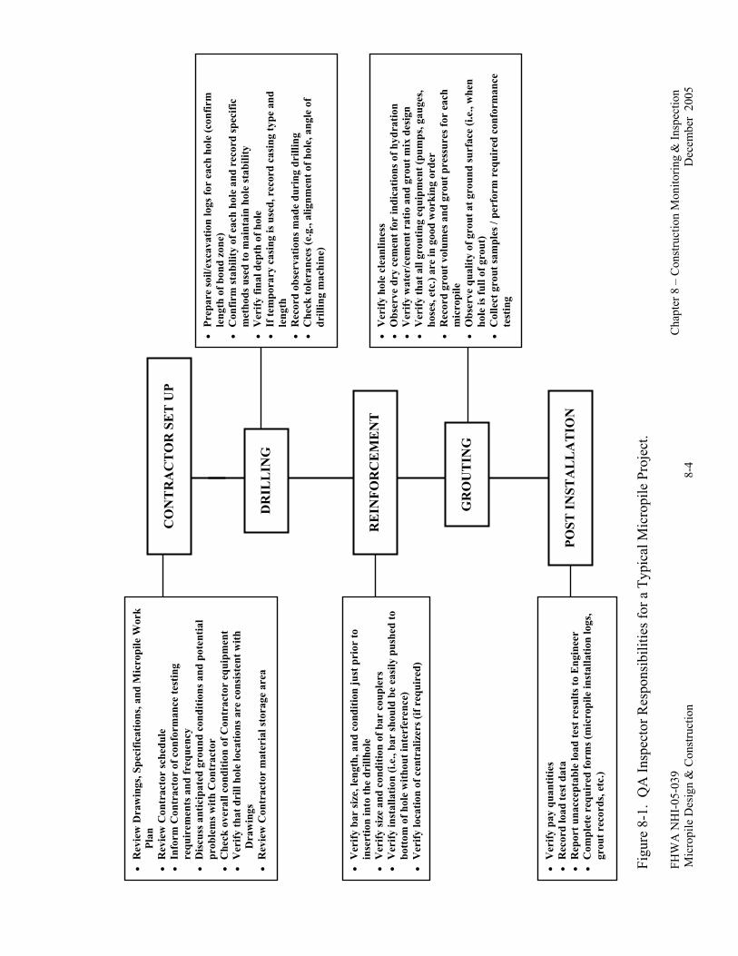
FHW
A N
HI-
05-0
39
C
hapt
er 8
– C
onst
ruct
ion
Mon
itorin
g &
Insp
ectio
n M
icro
pile
Des
ign
& C
onst
ruct
ion
8-4
Dec
embe
r 20
05
Fi
gure
8-1
. Q
A In
spec
tor R
espo
nsib
ilitie
s for
a T
ypic
al M
icro
pile
Pro
ject
.
RE
INFO
RC
EM
EN
T
• V
erify
hol
e cl
eanl
ines
s •
Obs
erve
dry
cem
ent f
or in
dica
tions
of h
ydra
tion
• V
erify
wat
er/c
emen
t rat
io a
nd g
rout
mix
des
ign
• V
erify
that
all
grou
ting
equi
pmen
t (pu
mps
, gau
ges,
hose
s, et
c.) a
re in
goo
d w
orki
ng o
rder
•
Rec
ord
grou
t vol
umes
and
gro
ut p
ress
ures
for
each
m
icro
pile
•
Obs
erve
qua
lity
of g
rout
at g
roun
d su
rfac
e (i.
e., w
hen
hole
is fu
ll of
gro
ut)
• C
olle
ct g
rout
sam
ples
/ pe
rfor
m r
equi
red
conf
orm
ance
te
stin
g
POST
INST
AL
LA
TIO
N
• V
erify
bar
size
, len
gth,
and
con
ditio
n ju
st p
rior
to
inse
rtio
n in
to th
e dr
illho
le
• V
erify
size
and
con
ditio
n of
bar
cou
pler
s •
Ver
ify in
stal
latio
n (i.
e., b
ar sh
ould
be
easi
ly p
ushe
d to
bo
ttom
of h
ole
with
out i
nter
fere
nce)
•
Ver
ify lo
catio
n of
cen
tral
izer
s (if
requ
ired
)
• V
erify
pay
qua
ntiti
es
• R
ecor
d lo
ad te
st d
ata
• R
epor
t una
ccep
tabl
e lo
ad te
st r
esul
ts to
Eng
inee
r •
Com
plet
e re
quir
ed fo
rms (
mic
ropi
le in
stal
latio
n lo
gs,
grou
t rec
ords
, etc
.)
CO
NT
RA
CT
OR
SE
T U
P
• R
evie
w D
raw
ings
, Spe
cific
atio
ns, a
nd M
icro
pile
Wor
k Pl
an
• R
evie
w C
ontr
acto
r sc
hedu
le
• In
form
Con
trac
tor
of c
onfo
rman
ce te
stin
g re
quir
emen
ts a
nd fr
eque
ncy
• D
iscu
ss a
ntic
ipat
ed g
roun
d co
nditi
ons a
nd p
oten
tial
prob
lem
s with
Con
trac
tor
• C
heck
ove
rall
cond
ition
of C
ontr
acto
r eq
uipm
ent
• V
erify
that
dri
ll ho
le lo
catio
ns a
re c
onsi
sten
t with
D
raw
ings
•
Rev
iew
Con
trac
tor
mat
eria
l sto
rage
are
a D
RIL
LIN
G
• Pr
epar
e so
il/ex
cava
tion
logs
for
each
hol
e (c
onfir
m
leng
th o
f bon
d zo
ne)
• C
onfir
m st
abili
ty o
f eac
h ho
le a
nd r
ecor
d sp
ecifi
c m
etho
ds u
sed
to m
aint
ain
hole
stab
ility
•
Ver
ify fi
nal d
epth
of h
ole
• If
tem
pora
ry c
asin
g is
use
d, r
ecor
d ca
sing
type
and
le
ngth
•
Rec
ord
obse
rvat
ions
mad
e du
ring
dri
lling
•
Che
ck to
lera
nces
(e.g
., al
ignm
ent o
f hol
e, a
ngle
of
drill
ing
mac
hine
)
GR
OU
TIN
G
FHWA NHI-05-039 Chapter 8 – Construction Monitoring & Inspection Micropile Design & Construction 8-5 December 2005
8.4 INSPECTION OF MICROPILE MATERIALS
8.4.1 General
Specifications describe minimum requirements for micropile materials. These minimum requirements may be defined explicitly or by reference to standard specifications such as those set forth by AASHTO and ASTM. Because the materials used to construct a micropile are common civil engineering materials, prequalified products are not commonly required, however, certain proprietary features may be involved in, for example, the micropile to footing connection. Recommendations for the storage and handling of selected materials are commonly included in specifications.
Conformance to a specification requirement is commonly assessed in one of the following ways: (1) reviewing manufacturer or supplier certification submitted by the contractor; (2) reviewing of product literature and visual inspection; or (3) conformance testing. All materials and prefabricated elements delivered to the site must be visually examined prior to installation to verify required geometry and dimensions and to identify any defects in workmanship, contamination, or damage by handling. All nonconforming materials are unacceptable, unless appropriate corrections are made in accordance with specifications or by written approval of the project engineer.
8.4.2 Storing and Handling of Cement
Cement is typically supplied either in bagged (43 kg/sack) or bulk (1320 kg/bulk bag) form, depending on site conditions, job size, local availability, and cost. Cement should not be stored directly on the ground or anywhere where it may be subject to significant moisture absorption. An example of appropriate cement storage is provided in Figure 8-2. The contractor should avoid stacking the bags too high to prevent over compaction of the cement.
Cement should be visually examined for lumps or other indications of hydration or contamination by foreign matter immediately prior to its use. The water used for grout mixing must be potable, and not contain impurities harmful to the steel or the grout. The contractor should also handle admixtures with care following manufacturer’s recommendations. Approved admixtures that have exceeded the manufacturer’s recommended shelf life should not be used.

FHWA NHI-05-039 Chapter 8 – Construction Monitoring & Inspection Micropile Design & Construction 8-6 December 2005
Figure 8-2. Cement Storage.
8.4.3 Storing and Handling of Reinforcing Steel
Steel reinforcement should be stored above the ground surface and be protected against mechanical damage and exposure to weather. Reinforcing bars should be lifted using fiber ropes or webbing and should be supported at several locations to prevent excessive bending.
The micropile contractor should use care in unloading and storing all reinforcing steel material. The storage area should be away from construction traffic and in a protected location. When reinforcing steel material is delivered to the job site, it should be visually checked for size and any signs of corrosion. Reinforcing steel elements should be accompanied by mill certificates. Mill secondary pipe materials, for which mill certificates will not be available, require verification of steel quality through tensile and chemical testing of steel samples. For Buy America Contracts, United States manufacturing of materials must be verified. All steel reinforcing materials shall conform to the proper standards as identified in the project specifications.
Properly stored steel reinforcing materials (see Figure 8-3) prevent corrosion or contamination by dirt, oils, and/or organics. Wood spacers placed between the ground and

FHWA NHI-05-039 Chapter 8 – Construction Monitoring & Inspection Micropile Design & Construction 8-7 December 2005
the steel materials will prevent slight rusting that can occur if steel is exposed to the ground. A light coating of surface rust on the steel is normal and indicates that oil and grease are not present. Deep flaky corrosion or deep pitting of the steel is cause for rejection. All steel materials should be inspected just prior to their use.
Double corrosion-protected and/or epoxy-coated steel bars should be delivered to the job site pre-manufactured (Figure 8-4). Extra care in handling and storage shall be given to these materials. Epoxy-coated bars shall be properly wrapped with padded bands and placed on wooden or padded supports. Pre-manufactured corrosion-protected steel bars must be stacked with care to prevent any damage to the corrugated tube and/or epoxy coating. Any repairs to epoxy coatings shall be performed in accordance with manufacturer’s recommendations.
Mechanical couplers, hex nuts, centralizers, and spacers are typically delivered to the job site in boxes. Mill certificates will be provided for the steel couplers and hex nuts. Storage of these materials shall follow the same procedures as other materials.
Figure 8-3. Storage of Reinforcing Steel.

FHWA NHI-05-039 Chapter 8 – Construction Monitoring & Inspection Micropile Design & Construction 8-8 December 2005
Figure 8-4. Double Corrosion Protected (Encapsulated) Reinforcing Steel.
8.5 INSPECTION OF CONSTRUCTION ACTIVITIES
8.5.1 Inspection of Drilling Activities
The contractor’s drilling operation should not cause unacceptable loss of ground. Signs of unacceptable loss of ground include the inability to withdraw the drill casing from the hole, large quantity of soil removal with little or no casing advancement, and subsidence of the ground above drilling location. The QA inspector should document this information and other observations of the drilling procedures in their daily reports.
When temporary casing is to be removed during the grouting process, it should be removed in a manner that does not cause the pile reinforcement to become disturbed, damaged, or allowed to loss contact with the in-situ soil. The casing should also be kept full of grout during the removal operation to minimize the potential for drillhole collapse. The contractor is responsible for implementing all measures required to maintain an open drillhole during construction. Fluid levels in the drillhole must always be kept above the ground water level to minimize potential ground losses into the drillhole from potentially unstable soils.

FHWA NHI-05-039 Chapter 8 – Construction Monitoring & Inspection Micropile Design & Construction 8-9 December 2005
The drilling, installation of reinforcement, and grouting of each micropile should be completed by the contractor in a series of continuous processes as expeditiously as possible. Some materials, such as consolidated clays and weak rock, can deteriorate and soften when exposed to air or water. Under these conditions, drilling of the pile bond zone, reinforcement installation, and grouting of the bond zone should be completed in one day. Unless micropile construction is continuous, the contractor should temporarily plug or cover the drillhole at the ground surface to prevent debris from falling into the borehole and for safety of the personnel working on the site. It is also recommended that casing material be placed (temporary or permanent project) a minimum of 0.3 m (1 ft) above the ground surface elevation to avoid drill spoils and flushing water from other operations flowing down and contaminating the completed hole.
The micropile contractor shall provide for proper disposal and containment of the drilling spoils from the site in accordance with the approved work plan. The drill water should be controlled at all times to prevent erosion and to prevent accumulation of standing water which may freeze or otherwise create sloppy working conditions.
Micropile inclination and position may need to deviate from that specified in the contract documents. Any deviation outside the tolerances provided in the Specifications, however, should be viewed as a design change and the contractor must notify the engineer of his intended change before implementing this change. In general, any deviations from the Drawings and Specifications should be recorded by the QA inspector and this information provided to the engineer.
8.5.2 Inspection of Reinforcement Installation Activities
Reinforcement may be placed either prior to drillhole grouting, or placed into the grout-filled borehole before temporary casing (if used) is withdrawn. In any case, the inspector shall record the total pile length and bond zone length for each installed micropile. The reinforcement shall be capable of being inserted to its prescribed length in the hole without force. Inability to achieve this penetration in uncased holes usually means caving of soil into the hole has occurred, and withdrawal of the reinforcement and redrilling is necessary. Driving the reinforcement to full length or cutting off the reinforcement shall not be allowed.
Care should be exercised so as not to damage corrosion protection measures or centralizers during reinforcement installation. Neither epoxy-coated, double corrosion-protected, or uncoated steel reinforcements should be dragged across abrasive surfaces or through the surface soil. All splices and couplings should be checked for proper seating. The reinforcement must be clean of deleterious substances such as surface soil, oil, and mud,

FHWA NHI-05-039 Chapter 8 – Construction Monitoring & Inspection Micropile Design & Construction 8-10 December 2005
which may contaminate the grout or coat the reinforcement. Centralizers and spacers shall be checked to ensure placement at specified intervals, typically 2.5 to 3 m (8 to 10 ft) (Figure 8-5). Attachment of the centralizers to the reinforcement should also be checked to ensure that the reinforcement remains centered in the borehole. Typically centralizers are attached with tie-wire or duct tape. If tremie grout tubes are placed after the reinforcement has been positioned, care should be exercised so that the tremie tube does not interfere with the centralizers.
8.5.3 Inspection of Grouting Activities
Before any grouting begins, the condition of the grouting equipment should be checked by the contractor and the grout-mix design should be verified. Care in execution of the grouting process can greatly impact the quality of the completed micropile and its load carrying capacity.
Prior to grouting, the inspector should verify the diameters of micropiles drilled without casings. Ideally, the contractor should grout the micropiles immediately after drilling the bond zone. However, if this is not possible, grouting should be performed before degradation of the drill hole.
Figure 8-5. Reinforcement Centralizers.

FHWA NHI-05-039 Chapter 8 – Construction Monitoring & Inspection Micropile Design & Construction 8-11 December 2005
The primary grouting operation involves injecting cement grout at the lowest point of the borehole so the hole will fill evenly without air voids. A tremie tube is typically tied to the reinforcing steel before insertion in the borehole. After placement of the reinforcement steel and tremie tube, the grout is pumped to the bottom of the pile until grout of suitable quality (of the same consistency as that being injected) returns to the top of the pile. The tremie tube is then removed from the micropile hole or left in the hole and filled with grout.
The Contractor should perform grouting in one continuous operation. Care should be taken to maintain a positive head at the grout holding tank to avoid drawing air into the injected grout. Pressure grouting may be applied to the primary grout during casing withdrawal. Care must be taken with such pressures to avoid distress to the ground or adjacent structures. The pressure grouting process should be discontinued if grout is observed escaping at the ground surface.
Grout pressures are measured as close to the point of injection as possible to account for line losses between the pump and the borehole. Typically, a pressure gauge is mounted on the drill rig and monitored by the drill rig operator as a guide during pressure grouting and casing withdrawal (Figure 8-6).
Figure 8-6. Drill Rig Pressure Gauge.

FHWA NHI-05-039 Chapter 8 – Construction Monitoring & Inspection Micropile Design & Construction 8-12 December 2005
For micropiles installed with a hollow-stem auger, the grout should be pumped under continuous pressure with a grout head maintained above the tip of the auger during auger withdrawl. The auger should be withdrawn in a controlled manner to minimize the potential for “necking” of the borehole to occur.
If post grouting is performed, it is very important to monitor grout pressures and volumes throughout the injection of each sleeve. This will help prevent dangerous or needless over injection and progressively verify the effectiveness of the treatment. Post grouting pressures have been documented in excess of 6.5 MPa (943 psi). Typical range during injection is 2 to 4 MPa (290 to 580 psi).
Grouting records are of vital importance on every project and are described in Section 8.6.3.
8.6 REQUIRED PROJECT DOCUMENTATION
8.6.1 Micropile Load Testing
During micropile load testing, the inspector must verify that the: (1) test pile installation method used is the same as will be used for the installation of the production piles; (2) pile load test setup is in accordance with the approved working drawings; and (3) pile is load tested in accordance with the project specifications. During load testing, the following general guidelines should be observed:
• at no time should the micropile be loaded such that the axial stresses within the micropile exceed maximum allowable stresses provided in the Specifications;
• at no time should the applied load be reduced below the alignment load; and • test measurements should be plotted as the test proceeds in order to identify unusual
behavior.
The QA inspector should check the following:
• testing apparatus alignment; • use of properly calibrated jacks and gauges; • dial gauge arm alignment and travel length; • dial gauge point of contact; • application of the proper loads and sequencing and duration of each load; and • potential interference points due to pile deflection.

FHWA NHI-05-039 Chapter 8 – Construction Monitoring & Inspection Micropile Design & Construction 8-13 December 2005
8.6.2 Production Micropiles
Comprehensive records of the micropile installation are required to establish the basis of payment and to identify potentially significant deviations from the Contract Documents. Table 8-1 shows an example micropile installation log to be used by the micropile contractor and the inspector. A completed micropile installation log is provided in Table 8-2 as an example.
8.6.3 Grouting Records for Production Micropiles
Because the grout is such a vital component of the micropile, close attention should be paid to the quality and control of the grout. Grout production and consumption records must be kept daily. It is important that the actual pressure and volume of grout pumped for each micropile be recorded by the contractor and the inspector.
Unconfined compressive strength of grout is determined according to AASHTO T106/ASTM C-109. Compressive strength is typically checked through a set of three each, 50-mm (2 in) grout cubes (Figure 8-7). Tests are typically performed at 3, 7, and 28 days after grouting. Seven-day tests are considered the most crucial, as the grout will typically attain the required design strength within this time period. Anticipated strength will depend upon project need, but compressive cube strengths can be very high, as much as 24 MPa (3,500 psi) after only 24 hours of set time. The unconfined compressive strength is largely dependent on project needs, but a 28-day strength requirement between 25 and 40 MPa (3,600 and 5,800 ksi) is considered common for micropiles. The inspector needs to verify that the grout cube break strengths comply with the project specifications. Grout samples should be taken directly from the grout plant. It is recommended that one set of three grout cubes be taken for every 10 micropiles installed, or every day for each grout plant in operation, whichever occurs more frequently.

FHWA NHI-05-039 Chapter 8 – Construction Monitoring & Inspection Micropile Design & Construction 8-14 December 2005
Table 8-1. Example Micropile Installation Log.
Project Name: Pile Designation #
Contract No.: Design Load Compress = Tension =
DESIGN AS-BUILT Installation Date
Pile Inclination Time @
Casing Dia./Wall Thickness Start of Drilling
Reinforcement Size/Length Start of Grouting
Casing Length below B.O.F. Pile Completion
Cased Bond Length (Plunge) Total Duration
Bond Length Below Casing ABBREVIATIONS
Total Pile Length below B.O.F. B.O.F. = Bottom of Footing
Casing Length above B.O.F.
PILE DRILLING
Drill Method Drill Rig #
Drill Bit Type and Size Drill Operator
Time Depth from B.O.F Soil / Rock Description Flush Return Description
Comments
PILE GROUTING
Grout Plant #, Operator Cement Type
Tremie Grout Quantity (bags) Admixtures
Pressure Grout Quantity (bags) w/c Ratio
Grouting after plunge (bags) Grout Ratio (bags/m bond)
Total Grout Quantity (bags)
Depth from B.O.F Pressure Range Max/Average Comments

FHWA NHI-05-039 Chapter 8 – Construction Monitoring & Inspection Micropile Design & Construction 8-15 December 2005
Table 8-2. Example Completed Micropile Installation Log.
Project Name: Keeley Palace Pile Designation #: Pile 1
Contract No.: 0064 Design Load Compress = Tension =
DESIGN AS-BUILT Installation Date 12-25-96
Pile Inclination 0 degrees Time @ 8:00 am – 9:20 am
Casing Dia./Wall Thickness 177/13 (mm) Start of Drilling 8:00 am
Reinforcement Size/Length 57( mm)/15.5 (m) Start of Grouting 9:00 am
Casing Length below B.O.F. 8 m Pile Completion 9:20 am
Cased Bond Length (Plunge) 2 m Total Duration 1:20
Bond Length Below Casing 6 m ABBREVIATIONS
Total Pile Length below B.O.F. 16.5 m B.O.F. = Bottom of Footing
Casing Length above B.O.F. 0.5 m
PILE DRILLING
Drill Method Cased Rotary Drill Rig # 10-1
Drill Bit Type and Size Casing Teeth – 175 mm Drill Operator Kilian
Time Depth from B.O.F Soil / Rock Description Flush Return Description
Comments
0 – 5 m Gravel and Cobbles Brown, full return
5 – 10 m Sand Gravel w/Cobbles Brown, full return
10 – 15 m Cobbles w/Gravel Gray, full return Occasional Sand Seams
PILE GROUTING
Grout Plant #, Operator 8-1, Holder Cement Type I / II
Tremie Grout Quantity (bags) 12 Admixtures None
Pressure Grout Quantity (bags) 13 w/c Ratio 0.45
Grouting after plunge (bags) 2 Grout Ratio (bags/m bond)
Total Grout Quantity (bags) 27
Depth from B.O.F Pressure Range Max/Average (MPa) Comments
15 – 10 m 0.55 / 0.45 Grouted first 3 m under pressure, pulled remainder under static head
10 – 5 m 0.55 / 0.47 Grouted first 3 m under pressure, pulled remainder under static head
Plunge, 5 – 6.5 m 1.2 After plunging casing, pumped additional 2 bags at max pressure = 1.2 MPa

FHWA NHI-05-039 Chapter 8 – Construction Monitoring & Inspection Micropile Design & Construction 8-16 December 2005
Figure 8-7. Grout Cubes for Compressive Strength Testing.
Specific gravity measurements of grout are frequently checked to determine the water content of the grout because the water content of the grout is the prime control over grout properties. Neat cement grout density can be determined per the American Petroleum Institute (API) Recommended Practice (RP) 13B-1 by the Baroid Mud Balance Test (Figure 8-8). The test is extremely quick and inexpensive and should be performed at least once per micropile. By monitoring the water/cement ratio during grouting, the inspector can ensure that the grout is being prepared according to the specified project mix design. A common specific gravity for grout is between 1.8 and 1.9, which corresponds to a water/cement ratio of 0.45.
Tests that permit quality assessment prior to installation are more valuable since they permit immediate reaction in case of anomalies. Compressive strength values; however may only be established 48 hours after the sampling at the earliest. Pre-construction testing of the grout should be performed prior to production drilling to verify acceptability of grout mix design such as prior to and/or during micropile verification load testing.

FHWA NHI-05-039 Chapter 8 – Construction Monitoring & Inspection Micropile Design & Construction 8-17 December 2005
Figure 8-8. Baroid Mud Balance Test.

FHWA NHI-05-039 Chapter 8 – Construction Monitoring & Inspection Micropile Design & Construction 8-18 December 2005
8.7 REFERENCES
ASTM C109, “Standard Test Method for Compressive Strength of Hydraulic Cement Mortars Using 2 in (50 mm) Cube Specimens”, American Society for Testing and Materials, New York.
AASHTO T106, “Standard Test Method for Compressive Strength of Hydraulic Cement Mortars Using 2 in (50 mm) Cube Specimens”, American Association of State Highway Transportation Officials, Washington, DC.
FHWA NHI-05-039 Chapter 9 – Contracting Methods Micropile Design & Construction 9-1 December 2005
CHAPTER 9 CONTRACTING METHODS
9.1 INTRODUCTION
The purpose of this chapter is to describe contracting approaches that are commonly used in developing contract documents for projects involving micropiles. Two types of contracting methods are used to develop contract drawings and specifications for micropiles. Some agencies prefer one approach to the other or a mix of approaches for micropiles based on the criticality and complexity of a particular project, experience of the owner and their engineering consultants, and the availability of specialty contractors. The selection of a contracting method may also depend on the experience of the agency with micropile technology. Both contracting approaches are valid if properly implemented and each has advantages and disadvantages. These contracting methods include:
Method (or Procedural) Approach. All details of design, construction materials, and methods are specified in the contract documents. A variant to this method allows the contractor to select micropile drilling and grouting methods required to achieve specified pile capacities.
Performance or End-Result Approach. Lines and grades with specific design criteria and methods and performance requirements are provided in the contract documents. With this approach, a project-specific review and detailed plan submittal occurs in conjunction with the submittal of working drawings.
Because specialty contractors often introduce innovative, cost-competitive solutions, it is recommended that the contract documents for micropile projects be structured to allow specialty contractors to make use of the latest available construction techniques. Thus, contract documents that are performance-based, with respect to drilling and grouting methods, are recommended. The performance approach and the variant of the method approach allow this flexibility.
9.2 CONTRACTOR QUALIFICATION
The procedures for micropile construction need to be followed closely to provide a high quality product. Selecting an experienced and qualified contractor to install micropiles is

FHWA NHI-05-039 Chapter 9 – Contracting Methods Micropile Design & Construction 9-2 December 2005
critical to obtain a satisfactory installation. The likelihood of success further increases when comprehensive construction quality assurance procedures are developed and enforced by the owner. Agencies or owners with no previous micropile experience should seek a qualified third-party quality assurance provider.
Contract documents for micropile projects should clearly define: (1) the contractor pre-qualification requirements; (2) submittal procedures for this qualification information; and (3) the means by which the owner will enforce these requirements. Such pre-qualification requirements are commonly being used by many transportation agencies for other specialty construction techniques, such as permanent ground anchors, soil nail walls, drilled shaft foundations, and shotcreting. However, where formal pre-qualification may not be allowed, agencies should request that bidders demonstrate that they meet specific micropile experience requirements.
The recommended minimum qualifications for each micropile contractor are provided below.
1. The contractor firm and its proposed employees for the project should provide evidence of previous successful experience in the design and installation of micropiles. Owner references in the design and installation of micropiles of similar scope to those proposed for the application project should be provided. Documentation shall include at least five successful projects performed in the last five years.
2. The contractor firm shall assign an engineer to supervise the work who has at least three years of experience in micropile design and construction of at least 3 successfully completed projects over the past 5 years.
3. The contractor firm must have previous drilling experience in similar ground to anticipated project conditions. The contractor firm must submit at least three successful load test reports from different projects of similar scope to project.
4. Project superintendents and drill operators responsible for installation of micropile system must have micropile installation experience on at least 3 successfully completed projects over the past 5 years.
9.3 METHOD CONTRACTING APPROACH
The method contracting approach includes the development of a detailed set of plans and specifications to be provided in the bidding documents. The advantage of this approach is that complete design details and specifications are developed and reviewed by experienced
FHWA NHI-05-039 Chapter 9 – Contracting Methods Micropile Design & Construction 9-3 December 2005
representatives. This approach further empowers agency engineers to examine options that may be available during design but requires engineering staff trained in micropile design and construction methods. The staff then also becomes a valuable asset during construction, when questions and/or design modifications are required.
Under this contracting procedure, the agency is fully responsible for the design and performance of the micropile, as long as the contractor has installed each component (e.g., pile casing, grout, steel reinforcement) in strict accordance with the contract documents. The agency assumes all risks and is responsible for directing the work if changes to the design are required based on actual field conditions. The use of a method specification is recommended only for agencies that have developed sufficient in-house expertise and consider micropile design and construction control as a conventional or standard method for foundation system or slope stabilization.
The use of a variant to this method, in which the contractor is responsible for developing the required pile capacity by varying the drilling and grouting methods, drill hole diameter, and length of piles from specified minimums, has several advantages. It empowers contractors to maximize the use of their experience and specialized equipment and allows the agency to share the major risk, (i.e., pile capacity for a specified length), with the contractor. The owner typically establishes the following:
• scope of work;
• micropile design loadings and spacing;
• footing details;
• corrosion protection;
• micropile testing procedures and requirements;
• instrumentation requirements (if any);
• special design considerations (e.g., scour and liquefaction potential); and
• performance criteria.
The micropile contractor specifies the following:
• micropile construction process;
• micropile type;

FHWA NHI-05-039 Chapter 9 – Contracting Methods Micropile Design & Construction 9-4 December 2005
• micropile design; and
• pile top to footing connection design.
This division of work allows the qualified specialty contractors to provide an economical micropile design, while satisfying the design requirements. This method also allows responsibility for the work to be shared between the owner and the micropile contractor. While this is slightly more restrictive than the contractor design/build specification method, it is still flexible enough to allow for some innovation and cost savings. Various types of owner-controlled design specifications are described subsequently.
9.3.1 Standard Design
The contract documents for the Standard Design Type are prepared to allow for various qualified micropile designs. The owner’s engineer provides the micropile design loadings, footing design, and pile layout for foundation support. In addition, the owner provides the following:
• geotechnical reports and data;
• micropile design parameters (foundation support projects only) including maximum pile sizes, axial pile loads, lateral pile loads, displacement requirements, and ductility requirements;
• existing utility plans;
• site limitations, including: (1) access limitations; (2) right of way; (3) scour potential; (4) liquefaction potential; (5) noise requirements; (6) vibration requirements; and (7) potential for hazardous and/or contaminated materials;
• contractor working drawing/design submittal and review requirements including time frame and information on penalties;
• material specifications;
• testing requirements;
• instrumentation requirements (if any);
• micropile acceptance criteria; and
• method of measurement and payment.

FHWA NHI-05-039 Chapter 9 – Contracting Methods Micropile Design & Construction 9-5 December 2005
It is recommended that micropile measurement and payment be performed on a unit-per-micropile basis separately for: (1) furnished and installed production piles; (2) verification testing; and (3) proof testing, except for piles founded in rock, for which an add/deduct footage price may be included.
During the bidding process, micropile contractors prepare a preliminary design and a firm cost proposal based on the owner’s plans and specifications. If the project is to be subcontracted, general contractors will receive bids from each specialty subcontractor and includes the best offer in their proposal. The name of the recommended micropile subcontractor is included in the general contractor’s bid, which is then submitted. Once the contract has been awarded, the selected specialty contractor prepares working drawings and design calculations and submits them to the engineer for review and approval. After acceptance of the design, construction begins.
9.3.2 Alternate Micropile Design
For the Alternate Microple Design method, the owner provides a base design in the contract documents utilizing a more traditional foundation support system. The contract documents allow alternate micropile designs to be submitted by the listed specialty contractors on a one-for-one pile replacement of the owner-designed pile system. The information described under Standard Design Type is also required. Alternatively, this approach can be used to allow micropile contractors to submit designs which include fewer higher capacity micropiles than the conventional pile footing design requires, and allows the owner’s engineer to maintain control of the footing design.
The information necessary in the contract documents is similar to that previously mentioned, except the owner provides two to three alternative pile footing designs on the plans with the associated pile design and load criteria.
9.3.3 Cost Reduction Incentive Proposal (Value Engineering)
The Cost Reduction Incentive Proposal is another long-established form of alternate proposal used in the United States. When Cost Reduction Incentive Proposals are permitted, it is important that the owner specify any additional restrictions that may apply, such as right-of-

FHWA NHI-05-039 Chapter 9 – Contracting Methods Micropile Design & Construction 9-6 December 2005
way restrictions. Foundation support elements are usually the first order of work, so review and approval of the Cost Reduction Incentive Proposal needs to be performed in a timely manner.
9.4 PERFORMANCE SPECIFICATIONS
This approach is often called “line and grade” or “conceptual plans”. Under this approach, the agency: (1) prepares drawings defining the geometric requirements for the structure and material specifications for the components; (2) defines performance requirements including factors of safety; and (3) indicates the range of acceptable construction and design methods.
This approach, when coupled with sound specifications and pre-qualification of contractors, offers several benefits. Design of the structure is performed by trained and experienced staff and can utilize contractors’ proprietary equipment and methods along with material components successfully and routinely used in the past. Also, the performance specification approach lessens engineering costs and manpower requirements for the agency and transfers some of the project design costs to construction. The disadvantage is that agency engineers must have adequate expertise to perform a design review, approve construction modifications, and engage a consultant with demonstrated proficiency in micropile technology. It is noted that the limitations previously described under the method approach for pre-qualification of contractors for certain public agencies also apply to pre-qualification with the performance contracting approach.
Bid quantities are obtained from specified pay limits denoted on the drawings and can be bid on a lump sum or unit-price basis. The basis for detailed designs to be submitted after contract award is detailed as a special provision, as would construction control and monitoring requirements. The special provision should clearly identify the required submittals, schedule for submittals, and schedule for review and approval of these submittals. Items to be contained in the special provision are calculations and shop drawing submittals.
In the design/build method, the owner’s engineer typically provides the following information:
• scope of work;
• total structure loads;
• footing details;
• corrosion protection;
FHWA NHI-05-039 Chapter 9 – Contracting Methods Micropile Design & Construction 9-7 December 2005
• micropile testing procedures and requirements;
• instrumentation requirements (if any);
• special design considerations (e.g., scour and liquefaction potential); and
• performance criteria.
The micropile contractor specifies the following:
• micropile construction process;
• micropile type and quantity;
• micropile design;
• revisions to footing details to accomodate micropile design; and
• pile top to footing connection design.
Based upon specified limitations and requirements, a design/build proposal is submitted, either before the bid advertisement (pre-bid), or after contract award (post-bid). Measurement and payment is typically made on a lump-sum basis.
9.5 DESIGN/BUILD APPROACH
9.5.1 General
In design/build construction, the specialty contractor becomes an important part of the project team and is involved in all foundation and ground-support aspects of the project. The micropile contractor is responsible for the adequacy of the design and construction and the owner is responsible for the accuracy of the information upon which the design is based. The two recommended types of contractor design/build specifications follow.
9.5.2 Postbid Design
The contract documents for the postbid design/build method are prepared to allow for various contractor-designed alternatives. The owner’s engineer provides design and detailing of ancillary structures, and the performance criteria and objectives necessary for the micropile system design and installation. This information includes, as a minimum, the following:
FHWA NHI-05-039 Chapter 9 – Contracting Methods Micropile Design & Construction 9-8 December 2005
• geotechnical reports and data;
• structure loadings (axial, lateral and moment);
• existing utility drawings;
• design criteria and parameters;
• site limitations (e.g., right of way);
• design and details of ancillary structures;
• contractor working drawing/design submittal and review requirements; and
• micropile acceptance criteria.
During the bidding process, the micropile contractors prepare a preliminary design and a firm cost proposal based on the owner’s plans and specifications. For subcontracted items, general contractors will receive bids from each specialty subcontractor and include the best cost proposals in their bids. The name of the recommended micropile subcontractors are included in the general contractor’s bid, which is then submitted. Once the contract has been awarded, the selected specialty contractor prepares their detailed design calculations and working drawing and submits them to the engineer for review and approval. After acceptance of the design, construction begins.
9.5.3 Prebid Design
The contract documents for the prebid design/build method are also prepared to allow for contractor-designed micropiling alternatives. The major difference in this method is the timing of the design and the bidding. Performance criteria and necessary project design information are usually made available 60 to 90 days prior to the contract advertisement date. Micropile contractors prepare and submit final design calculations and working drawings for the owner’s review and approval. Once the designs (typically two to three total) are approved, a list of specialty contractors with approved designs are included in the contract documents. Often the specialty contractors’ proprietary working drawings are included in the contract bid documents. These drawings illustrate the proposed construction and assist the general contractors in understanding and coordinating their other project tasks with the proposed micropile construction. General contractors then receive bids from each subcontractor, bidding only on their own proprietary design, and include the best cost proposal in their bid. The name of the recommended micropile subcontractor is included in

FHWA NHI-05-039 Chapter 9 – Contracting Methods Micropile Design & Construction 9-9 December 2005
the general contractor’s bid, which is then submitted. Once the contract is awarded, the selected general contractor and specialty micropile contractor can begin work immediately.
9.6 CONTRACT PLANS
For all of the specification methods mentioned, the contract plans must include sufficient information to allow the contractor to develop a bid proposal that meets the owner’s objectives. The quality of the subsurface information, existing utility plan, and micropile design criteria are very important for a successful project. Inadequate subsurface information and conservative pile design criteria may create expensive contractor contingencies, higher pile prices and increase claim potential.
Sample contract plans and guide construction specifications utilizing owner controlled design methods is provided in Appendix C-1 and utilizing contractor design/build methods is provided in Appendix C-2.

FHWA NHI-05-039 Chapter 9 – Contracting Methods Micropile Design & Construction 9-10 December 2005

FHWA NHI-05-039 Chapter 10 – Cost Estimating Micropile Design & Construction 10-1 December 2005
CHAPTER 10 COST ESTIMATING
10.1 INTRODUCTION
The purpose of this chapter is to present an approach that may be used to develop a cost estimate for any micropile project. The cost estimate method described is similar to that commonly used in engineering to develop a conceptual cost estimate. That is, sufficient detail is used to identify the cost components which may have the largest effect on total project cost, however specific bid quantities and potential bidding contractors is not necessarily known.
The method requires that a baseline cost for micropiles be known. Over the past ten years, numerous micropile projects have been completed in the United States and typical micropile costs have decreased during this time period mostly due to experience gained by specialty micropile contractors and advances in micropile installation equipment. In 2004, a reasonable “average” price for micropiles is on the order of $300 per linear meter of micropile. This value is considered to be appropriate for any region of the U.S. and for any type of micropile project. The cost estimate method presented herein is used to adjust this baseline average price to account for project-specific technical and non-technical constraints.
Prior to describing the cost estimating method for micropiles, a discussion on the key factors which affect micropile costs is presented.
10.2 FACTORS THAT INFLUENCE MICROPILE COSTS
10.2.1 Overview
Table 10-1 provides a breakdown of the typical ranges of costs for materials, labor, and equipment for micropiles. Also listed as a separate component is load testing costs. In many cases, load testing costs may be paid for as a separate pay item.
10.2.2 Micropile Material Costs
The principal material components of micropiles include threaded steel casings, cement grout, steel reinforcing bars, and centralizers. Because of higher load capacities that continue to be achieved by micropiles, it is clear that costs for structural steel within the micropile cross section represent a significant cost component.

FHWA NHI-05-039 Chapter 10 – Cost Estimating Micropile Design & Construction 10-2 December 2005
Table 10-1. Typical Breakdown of Micropile Unit Costs.
Unit Cost Breakdown Percent
Material 25 – 40
Equipment 20 – 30
Labor 25 – 60
Load Testing <5
Threaded Steel Casing
The most commonly used casings for micropile applications in the United States have outside diameters of 140 mm (5.5 in.), 175 mm (7 in.), and 241 mm (9-5/8 in.). The cost of each casing type (without threads) is provided in Table 10-2. These costs are subject to relatively large fluctuations in the prevailing cost of steel and the costs provided are considered to be representative for 2004. In some cases, contractors may have access to previously used casings which would likely reduce steel material costs.
Table 10-2. Material Costs of Steel Casings Used for Micropiles. Casing Outside Diameter Casing Wall Thickness Cost of casing ($)
(mm) (in) (mm) (in) per meter per foot
139.7 5.500 10.5 0.415 15 – 25 5 – 8
177.8 7.000 12.6 0.498 35 – 45 11 – 14
244.5 9.625 13.8 0.545 50 – 60 15 – 18
Note: Representative early 2004 costs.
Because of low headroom conditions or difficult access, micropile casings are oftentimes installed in relatively short sections, thereby requiring a means to connect individual casing sections. Joints for casing are typically flush threaded joints. Threading costs wherein both ends are threaded (i.e., male and female threads) will typically cost in the range of $50 to $70 (2004) per casing. Therefore, where short casing lengths are required, threading costs can be relatively significant and the Owner should carefully assess the specific requirements for casing section lengths for a project. For example, where the cost of a 1-m-long 140-mm-
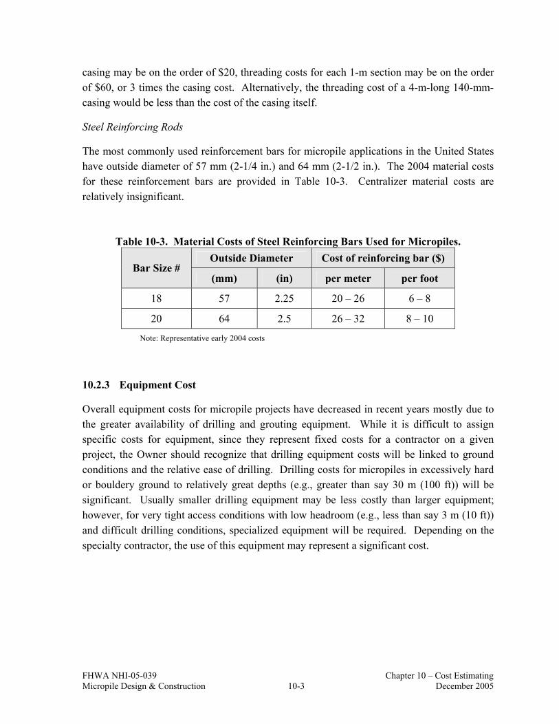
FHWA NHI-05-039 Chapter 10 – Cost Estimating Micropile Design & Construction 10-3 December 2005
casing may be on the order of $20, threading costs for each 1-m section may be on the order of $60, or 3 times the casing cost. Alternatively, the threading cost of a 4-m-long 140-mm-casing would be less than the cost of the casing itself.
Steel Reinforcing Rods
The most commonly used reinforcement bars for micropile applications in the United States have outside diameter of 57 mm (2-1/4 in.) and 64 mm (2-1/2 in.). The 2004 material costs for these reinforcement bars are provided in Table 10-3. Centralizer material costs are relatively insignificant.
Table 10-3. Material Costs of Steel Reinforcing Bars Used for Micropiles. Outside Diameter Cost of reinforcing bar ($)
Bar Size # (mm) (in) per meter per foot
18 57 2.25 20 – 26 6 – 8
20 64 2.5 26 – 32 8 – 10
Note: Representative early 2004 costs
10.2.3 Equipment Cost
Overall equipment costs for micropile projects have decreased in recent years mostly due to the greater availability of drilling and grouting equipment. While it is difficult to assign specific costs for equipment, since they represent fixed costs for a contractor on a given project, the Owner should recognize that drilling equipment costs will be linked to ground conditions and the relative ease of drilling. Drilling costs for micropiles in excessively hard or bouldery ground to relatively great depths (e.g., greater than say 30 m (100 ft)) will be significant. Usually smaller drilling equipment may be less costly than larger equipment; however, for very tight access conditions with low headroom (e.g., less than say 3 m (10 ft)) and difficult drilling conditions, specialized equipment will be required. Depending on the specialty contractor, the use of this equipment may represent a significant cost.

FHWA NHI-05-039 Chapter 10 – Cost Estimating Micropile Design & Construction 10-4 December 2005
10.2.4 Labor Cost
A typical micropile crew consists of four individuals including a project superintendent, drilling operator, and two laborers. The effect of labor on micropile unit costs are directly linked to the ease of installation and daily micropile installation rates.
For projects involving relatively easy drilling and low to moderate capacity micropiles, a typical crew may install up to 6 to 20, 15-m (50-ft) long (maximum) micropiles per day. For such a project, labor may comprise 25 to 30 percent of the total project cost. However, in tight access areas and difficult drilling conditions the labor cost may increase to 30 to 45 percent of the total cost due to extra time and effort required. In extra labor-intensive projects and where prevailing labor costs are high (e.g., major urban areas), labor cost may comprise up to 60 percent of the micropile costs.
10.2.5 Load Testing Costs
Load testing costs depend on the access conditions of the site, the type of testing (i.e., compression, tension, and/or lateral load testing), the number of tests, testing protocol (i.e., “quick” load or standard load tests), and the required load capacity.
The engineer will typically select the number and type of load tests, however, compression load tests will always be more expensive than a comparable (i.e., similar maximum testing load) tension test. The primary reason for this is that reaction piles or anchors need to be constructed for the compression test. The cost range for verification load tests range from $10,000 to $25,000 per test with the lower end of the range being representative for tension tests and the upper end being representative for compression tests. Proof tests (which are commonly carried to significantly lower loads than verification tests and which are performed in less time) range in cost from $6,000 to $10,000. These costs are considered representative for typical projects.
Where very difficult access limits equipment access, load testing costs can be significantly higher. For example, high load capacity load tests in an easy access area may be on the order of $25,000 per test whereas for difficult access areas and where relatively high load capacities need to be verified (e.g., greater than 200 tons), load tests could be greater than $50,000 per test.

FHWA NHI-05-039 Chapter 10 – Cost Estimating Micropile Design & Construction 10-5 December 2005
10.3 MICROPILE COST ANALYSIS
10.3.1 Overview
An Owner considering the use of micropiles for a project may use the previously provided average cost of $300 per linear meter with the modifications provided in Table 10-4 to develop a preliminary cost estimate for their specific project. Table 10-4 has been developed based on micropile contractor input and reflects the relative effect of project-specific factors on micropile construction costs. The use of this table is described subsequently using two example projects and additional discussion on the specific factors provided in this table is also provided.
Table 10-4. Effects of Project-Specific Factors on Micropile Cost.
Cost Factor Influence Range Cost Influence
Physical and access conditions Very easy to very difficult 0% to +100%
Geology/ground conditions Very easy to very difficult 0% to +50%
Pile capacity Very low to very high(1) -30% to +30%
Pile lengths Very short to very long(2) -25% to +25%
Pile quantities Very high to very low(3) -50% to +100%
Testing requirements Very low to very high(4) -10% to +10%
Mobilization/demobilization One to multiple 0% to +10%
Continuous drilling operations Continuous to not continuous(5) 0% to +25%
Union agreements Nonunion to very strong -15% to +30%
Overhead and profit Very low to very high -10% to +100%
Notes: (1)Moderate pile capacity = 1,000 kN (225 kips). (2)Average pile length = 15 m (50 ft). (3)Average pile quantity = 50. (4)Average is one verification test and proof testing 5% of all piles. (5)Not continuous drilling operation implies significant down time periods during drilling operations.

FHWA NHI-05-039 Chapter 10 – Cost Estimating Micropile Design & Construction 10-6 December 2005
10.3.2 Effects of Project-Specific Constraints on Cost
The first two factors in Table 10-4 concerning access and ground conditions are shown to have a large effect on micropile cost. Effects related to difficult access and difficult ground conditions (e.g., drilling in excessively hard ground), however, would likely have a similar cost implication for driven piles and drilled shafts as well.
Pile capacity affects cost since higher capacity micropiles will require longer bond zone lengths which may comprise longer rock sockets than would be required for more moderately loaded micropiles. Also, greater structural requirements (i.e., increased steel area) are associated with higher capacity micropiles.
The length of a pile effects costs in several ways, for example:
• the longer the pile length, the more individual sections of steel casing will be required;
• beyond certain lengths, drilling costs may increase because of the need for more robust equipment to reach greater depths; and
• greater need may exist for hole stabilization at significant depths.
Table 10-4 indicates that the most significant relative cost reduction is associated with pile quantities. Large pile projects will enable the contractor to define project backlog and long-term personnel requirements.
The last entry in Table 10-4 (i.e., overhead and profit) relates to perceived contractor risk for a particular project. While this factor may be difficult for an Owner to assess as part of a preliminary cost estimate, should other factors in Table 10-4 generally result in increases above the average cost, it is reasonable to assume that a contractor may view the project as containing relatively significant risk, especially where ground conditions are expected to result in difficult drilling and low productivity.
10.3.3 Micropile Cost Estimate Examples
The use of Table 10-4 is demonstrated in two sample problems provided below.
10.3.3.1 Sample Problem No. 1 (Bridge Abutment Support)
Given: Single-span bridge located in mountainous terrain approximately 125 km northwest of Denver, Colorado. Each abutment is to be supported on 12 CASE 1, Type B micropiles with ultimate capacities of 1,190 kN (270 kips) in compression, and 490 kN (110 kips) in tension, and approximately 12 m (40 ft)

FHWA NHI-05-039 Chapter 10 – Cost Estimating Micropile Design & Construction 10-7 December 2005
in length. Testing requirements are one verification pile load test (compression only) on a sacrificial pile and two proof tests. Access to each work bench must be established. Drilling of bond zone is expected to be very difficult, due to cobbles and boulders. Drilling will be continuous at each location with an additional set-up of Abutment 2.
Solution: Evaluate each influence factor as shown in Table 10-5 below and multiply by cost of micropile per meter price.
Based on Table 10-5 the cost is adjusted as:
micropile ofmeter linear / 555$100851 x $300 ($)cost Average =
+=
The length of each micropile is 12 m (40 ft), therefore the unit price would be;
Average cost ($) = $555 x 12 m = $6,660 / each
Table 10-5. Sample Problem No. 1 – Cost Analysis (Bridge Abutment Support).
Cost Factor Influence Cost Influence (%)
Physical and access conditions Easy access 10
Geology/ground conditions Difficult drilling 30
Pile capacity Moderate pile capacity 0
Pile lengths Average pile lengths 0
Pile quantities Low pile quantities 25
Testing requirements Average # of testing 10
Mobilization/demobilization One mobilization 0
Continuous drilling operations Two setups 5
Union agreements Standard union agreements 0
Overhead and profit High-risk project 5
Total: 85%

FHWA NHI-05-039 Chapter 10 – Cost Estimating Micropile Design & Construction 10-8 December 2005
10.3.3.2 Sample Problem No. 2 (Seismic Retrofit)
Given: Seismic retrofit of a 200-m (650-ft) long concrete viaduct located in San Francisco, California. A total of 30 footings need retrofitting with 12 Type B micropiles per footing (resulting in a total of 360 micropiles for the project). Ultimate capacities are 2,500 kN (560 kips) in compression and 1,500 kN (340 kips) in tension. Subsurface profile includes approximately 10 to 12 meters (330 to 40 ft) of medium dense silty sands over weathered to moderately weathered serpentine bedrock. Micropiles average approximately 20 meters (66 ft) in length. Testing requirements include 1 verification pile load test (compression only) on a sacrificial pile and 30 proof tests. Access to each pile location is good, and overhead clearance varies between 5 to 12 meters (16 to 40 ft) for each footing. Drilling is assumed to be continuous allowing setups between each footing.
Solution: Evaluate each influence factor as shown in Table 10-6 below and multiply by cost of micropile per meter price.
Based on Table 10-6 the cost could be adjusted as:
micropile ofmeter linear / 330$100101 x $300 ($)cost Average =
+=
The length of each micropile is 20 m, therefore the unit price would be;
Average cost ($) = $330 x 20 = $ 6,600 / each
10.4 MEASUREMENT AND PAYMENT FOR MICROPILES
Table 10-7 provides a summary of typical pay items for a micropile project. It is recognized that design-build projects may use lump sum units for most of the pay items. With respect to payment for the micropile itself, alternative pricing may include payment per unit length of micropile or payment per pile with an add or deduct if actual pile lengths vary from a predetermined pile length used for the bid.

FHWA NHI-05-039 Chapter 10 – Cost Estimating Micropile Design & Construction 10-9 December 2005
Table 10-6. Sample Problem No. 2 – Cost Analysis (Seismic Retrofit).
Cost Factor Influence Cost Influence (%)
Physical and access conditions Easy access 10
Geology/ground conditions Easy drilling 10
Pile capacity High pile capacities 10
Pile lengths Moderate pile lengths 0
Pile quantities Large pile quantity -30
Testing requirements Relatively extensive 5
Mobilization/demobilization One mobilization 0
Continuous drilling operations Continuous drilling 0
Union agreements Strong union 10
Overhead and profit Lower risk project -5
Total 10%
Additional pay items will be required for projects involving difficult ground in which specific problems may be anticipated during the bid period. For example, where micropiles are to be installed in karstic regions, a pay item should be developed for grout volume above some minimum volume. However, specifications should require that where grout volumes are no greater than two times the theoretical volume of the drillhole, that there is no additional compensation for grouting, i.e., the per pile cost for a micropile shall include grout volumes up to two times the theoretical grout volume. Also, if obstructions are anticipated, the specifications should include a pay item for removal of obstructions. Payment for obstruction removal may be performed on a time and material basis. Where this approach is used, it is important to use a contractor with previous experience in similar ground conditions and to provide full-time construction inspection during obstruction removal. Whenever a time and material basis may be used for payment on a project, the Owner should request detailed information on labor and material charges as part of the contractor’s bid.

FHWA NHI-05-039 Chapter 10 – Cost Estimating Micropile Design & Construction 10-10 December 2005
Table 10-7. Micropile Measurement and Payment Units.
Description Unit
Mobilization/Demobilization Lump sum
Conduct Preproduction Test Pile Program Lump sum
Verification Load Test Per each
Proof Load Test Per each
Furnish and install micropile (foundation support) Per each
Furnish and install micropile (slope stabilization) Per lineal meter of
cap beam

FHWA NHI-05-039 Glossary Micropile Design & Construction Glossary-1 December 2005
GLOSSARY OF TERMS
Admixture: Substance added to the grout to control bleed and/or shrinkage, improve flowability, reduce water content, or retard setting time.
Alignment Load (AL): A minimum load applied to micropile during testing to keep the testing equipment correctly positioned.
Bond Length or Bond Zone: The length of the micropile that is bonded to the ground and used to transfer the applied axial loads to the surrounding soil or rock.
Bond-breaker: A sleeve placed over the steel reinforcement to prevent load transfer.
CASE 1 Micropile: A pile designed to accept vertical or lateral load directly, and transfer it to an appropriate bearing stratum. Usually includes significant steel reinforcement.
CASE 2 Micropile: One of a network of low-capacity piles used to delineate and internally reinforce a volume of soil.
Casing: Steel tube introduced during the drilling process in overburden soil to temporarily stabilize the drill hole. This is usually withdrawn as the pile is grouted, although in certain types of micropiles, some casing is permanently left in place to reinforce the unbonded length or provide additional capacity.
Centralizer: A device to support and position the reinforcing steel in the drill hole and/or casing so that a minimum grout cover is provided.
Coarse-grained Soils: Soils with more than 50 percent of the material by weight, larger than the No. 200 (0.075 mm) sieve size.
Cohesive Soils: Fine-grain soils that exhibit plasticity. Atterberg limits are commonly used to determine plasticity and better define a soil as cohesive or noncohesive.
Contractor: The person/firm responsible for performing the micropile work.
Corrosion-inhibiting Compound: Material used to protect against corrosion and/or lubricate the reinforcing steel.
Coupler: A device by which the pile load capacity can be transmitted from one partial length of reinforcement to another.

FHWA NHI-05-039 Glossary Micropile Design & Construction Glossary-2 December 2005
Creep Movement: The movement that occurs during the creep test of a micropile under a constant load.
Design Load (DL): The maximum load expected to be applied to the micropile during its service life.
Duplex Drilling: An overburden drilling system involving the simultaneous advancement of (inner) drill rod and (outer) drill casing. Flush from the inner drill rod exits the hole via the annulus between rod and casing.
Elastic Movement: The recoverable movement measured during a micropile test.
Encapsulation: A grout filled corrugated or deformed tube protecting the reinforcing steel against corrosion.
Fine-grained Soils: Soils with at least 50 percent of the material, by weight, smaller than the No. 200 (0.075 mm) sieve size.
Free (unbonded) Length: The designed length of the micropile that is not bonded to the surrounding ground or grout during stressing.
Maximum Test Load: The maximum load to which the micropile is subjected during testing.
Micropile: A small-diameter (typically less than 300 mm) drilled and grouted replacement pile which is typically reinforced.
Non-cohesive Soils: Granular soils that are generally nonplastic.
Overburden: Material, natural or placed, that requires cased drilling methods to provide an open borehole to underlying strata.
Permanent Micropile: Any micropile for permanent use, generally with more than a 24-month service life. May require special design, corrosion protection, and supervision during installation.
Plunge Length: The length that the pile casing is inserted into the bond zone.
Post-grouting: The injection of additional grout into the load transfer length of a micropile after the primary grout has set. Also known as regrouting or secondary grouting.
Preloading: Loading the micropile prior to the connection to the structure, to minimize or eliminate any structural movement in service.

FHWA NHI-05-039 Glossary Micropile Design & Construction Glossary-3 December 2005
Primary Grout: Portland-cement-based grout injected into the micropile hole prior to or after the installation of the reinforcement to direct the load transfer to the surrounding ground.
Proof Test: Incremental loading of a production micropile, recording the total movement at each increment.
Reinforcement: The steel component of the micropile that accepts and/or resists applied loadings.
Residual Movement: The nonrecoverable movement of a micropile measured during load testing.
Sheath: A smooth or corrugated pipe or tube that protects the reinforcing steel against corrosion.
Single-tube Drilling: The advancement of a steel casing through overburden, usually aided by water flushing through the casing. The water may or may not return to the surface around the casing, depending largely on the permeability of the overburden.
Spacer: A device to separate elements of a multiple-element reinforcement to ensure full bond development of each steel element.
Temporary Micropile: Any micropile for temporary use, generally with less than a 24-month service life.
Ultimate Grout-to-Ground Bond Values: The estimated ultimate geotechnical unit grout-to-ground bond strength selected for use in design.
Verification Load Test: Non-production (sacrificial) pile load test performed to verify the design of the pile system and the construction methods proposed, prior to installation of production piles.
Working Load: Equivalent term of Design Load.

FHWA NHI-05-039 Glossary Micropile Design & Construction Glossary-4 December 2005

FHWA NHI-05-039 Appendix A Micropile Design & Construction A-1 December 2005
APPENDIX A
DESIGN CONCEPT OF
CASE 2 MICROPILE NETWORKS
FOR SLOPE STABILIZATION

FHWA NHI-05-039 Appendix A Micropile Design & Construction A-2 December 2005
The CASE 2 micropile network design concept developed by Dr. Lizzi and illustrated in Figure 3-14 consists of “a three-dimensional lattice structure built into the soil according to a pre-established scheme depending on the purpose that the structure has to carry out,” (Lizzi 1971). The purpose of the micropile network for slope stability is two fold:
a) The micropiles must retain the soil and prevent its “flow” through the network formed by the piles, which would cause a reduction of the continuity and the unity of the composite gravity structure.
b) The micropiles must supply a nailing of the various soil layers by providing additional shear resistance along the possible critical sliding surfaces.
The soil-pile interaction for such micropile networks is very complex and there are many factors whose influence on the final behavior of the structure cannot be conveniently assessed. Lizzi suggested that designs be based on “some simple assumptions” using the concept of reinforced soil, and those used for reinforced concrete. The soil supplies the weight in a manner more or less as supplied in a monolithic gravity wall, whereas the micropiles, introducing reinforcing elements into the soil, supply the lines of force, allowing the composite mass to support compression, tension, and shear stresses. The system is based on the micropile-soil interaction, which results in a network (or “knot”) effect provided the micropiles are not too far apart.
The first official test on a full-size reticulated micropile structure was performed in 1957 for the Milan, Italy subway system. The knot affect has been confirmed by both model and earlier field tests (Lizzi 1978, Plumelle 1984, and Korfiatis 1984). Apart from several earlier tests on models and full-scale structures, a recent French National Project on micropiles (FOREVER 2003) includes experimental studies on the behavior of micropile networks. The findings of this research indicates that in loose to medium dense granular soils, a positive network effect can be obtained if adequate densification of the soil is assured and if the micropiles are concentrated as much as possible under the applied load. According to the researchers, this implies that the micropiles do not move apart or diverge from the surface of the foundation but, rather turn inwards in order to ensure a maximum densification of the soil. No design guidelines have been developed as yet from this project.
The design of Case 2 micropiles assumes a highly redundant system in which no tension is applied to any of the piles. Therefore, the system is subjected to compression and shear and the micropile network provides confinement to the in-situ soil, thereby improving its deformation modulus and increasing its shear resistance. The behavior of this system depends to a great extent on the knot effect concept and the reinforced concrete analogy. Once the knot effect is assured, the micropile enclosed soil mass behaves as a coherent body

FHWA NHI-05-039 Appendix A Micropile Design & Construction A-3 December 2005
and is analyzed as a gravity retaining structure. Using this concept, the following steps can be followed for preliminary design of Case 2 micropile networks:
1. Conduct a slope stability analysis to determine the increased resistance required (Hreq) along an existing failure surface to provide a specified target factor of safety, FSTARGET.
2. Develop the initial geometry of the micropile structure. Assume a pile configuration that
is dense enough to assure a knot effect and minimize the possibility of plastic flow between piles. A preliminary configuration can be based on density of 6 to 7 piles per linear meter along the wall alignment. Stability related to the plastic flow of soil between piles can be verified using the methods presented in Section 6.6.7.
3. Check the external stability of the micropile structure
3.1. Estimate the earth pressure against the micropile structure using conventional earth pressure theories.
3.2. Check the factor of safety against overturning (FSOV) assuming the micropile
structure is a rigid body:
2.0 MM = SF
goverturnin
resistingOV ≥
∑∑
(Eq. A-1)
To resist the overturning moment and to maintain compression stresses in the soil and in all micropiles, the resultant vertical force (from earth pressures and other external forces) should act in the middle third of the micropile structure.
3.3. Check the factor of safety against sliding (FSSL):
1.5 Loads Horizontal
piles) ofcapacity (Shear + soil) base ofstrength ar Loads)(She Vertical( = SF SL ≥∑
∑ (Eq. A-2)
3.4. Assume a micropile cross section and determine the contact stresses at the edge of
the base of the micropile structure for a given micropile cross section. The contact stresses at the edges of the micropile structure is calculated according to:
±=
2b
IeP
AP
transtrans
σ (Eq. A-3)

FHWA NHI-05-039 Appendix A Micropile Design & Construction A-4 December 2005
Where: P = vertical component of the resultant force acting on the structure; e = eccentricity of the force P; Atrans = area of the transformed micropile section; Itrans = moment of inertia at the base of the structure; and
b = width of the transformed section.
The transformed section area, Atrans is calculated as:
EEA+
EEA= A
soil
stlstl
soil
concconctrans (Eq. A-4)
Where:
Aconc = area of the concrete; Astl = area of the steel; Econc = Young’s modulus of the concrete; Estl = Young’s modulus of the reinforcing steel; and Esoil = Young’s modulus of the soil.
The moment of inertia at the base at the structure, Itrans, is computed by assigning equivalent areas of soil to the concrete and steel based upon the ratios of Young’s moduli.
The minimum stress calculated according to Eq. A-3 should be positive indicating that all contact stresses are in compression.
3.5. Using the stresses computed, determine the maximum compression stresses in
each component of the composite section (i.e., concrete, steel reinforcement, and soil). Check these compression stresses against allowable design values.
4. Check the internal stability of the micropile structure
Design each micropile to resist the stresses calculated in Step 3.5. Compute shear resistance of the piles and the lateral resistance of the soil in contact with the piles. The smaller of the two resistances is considered as the additional shear resistance due to micropiles (R1).

FHWA NHI-05-039 Appendix A Micropile Design & Construction A-5 December 2005
5. Determine the number of micropiles (n) for the micropile structure using:
( )DH R
FS reqTARGET
+= and 1req Rn H = (Eq. A-5)
Where:
R = horizontal component of the soil resisting forces along the critical slip surface; and
D = horizontal component of the driving force along the critical slip surface. The above referenced design procedure has not yet been proven by long term instrumented field performance. It is recommended that owners considering the use of these types of slope stabilization structures implement a long-term instrumentation program to fully understand the behavior and performance of the structure.

FHWA NHI-05-039 Appendix A Micropile Design & Construction A-6 December 2005

FHWA NHI-05-039 Appendix B Micropile Design & Construction B-1 December 2005
APPENDIX B
LPILE ANALYSIS RESULTS FOR SLOPE STABILIZATION PROBLEM
FHWA NHI-05-039 Appendix B Micropile Design & Construction B-2 December 2005
============================================================== LPILE Plus for Windows, Version 4.0 (4.0.8) Analysis of Individual Piles and Drilled Shafts Subjected to Lateral Loading Using the p-y Method (c) Copyright ENSOFT, Inc., 1985-2003 All Rights Reserved ============================================================== Path to file locations: L:\Programs\LPILE\Chapter 6\Ch. 6 Example with P=474.5\ Name of input data file: 1st analysis.lpd Name of output file: 1st analysis.lpo Name of plot output file: 1st analysis.lpp Name of runtime file: 1st analysis.lpr ------------------------------------------------------------------------------ Time and Date of Analysis ------------------------------------------------------------------------------ Date: May 4, 2005 Time: 15:26: 0 ------------------------------------------------------------------------------
Problem Title ------------------------------------------------------------------------------
1st Analysis (To Determine Mult for P=0 and P=Pult Cases) ------------------------------------------------------------------------------ Program Options ------------------------------------------------------------------------------ Units Used in Computations - SI Units, meters, kilopascals Basic Program Options: Analysis Type 3: - Computation of Nonlinear Bending Stiffness and Ultimate Bending Moment Capacity with Pile Response Computed Using Nonlinear EI Computation Options: - Only internally-generated p-y curves used in analysis - Analysis uses p-y multiplers for group action - Analysis assumes no shear resistance at pile tip - Analysis for fixed-length pile or shaft only - No computation of foundation stiffness matrix elements - Output pile response for full length of pile - Analysis assumes no soil movements acting on pile - Additional p-y curves computed at specified depths Solution Control Parameters: - Number of pile increments = 145 - Maximum number of iterations allowed = 100 - Deflection tolerance for convergence = 10.000E-07 m - Maximum allowable deflection = 2.5400E+00 m Printing Options: - Values of pile-head deflection, bending moment, shear force, and soil reaction are printed for full length of pile. - Printing Increment (spacing of output points) = 1 ------------------------------------------------------------------------------ Pile Structural Properties and Geometry ------------------------------------------------------------------------------ Pile Length = 14.50 m Depth of ground surface below top of pile = .00 m Slope angle of ground surface = .00 deg. Structural properties of pile defined using 2 points
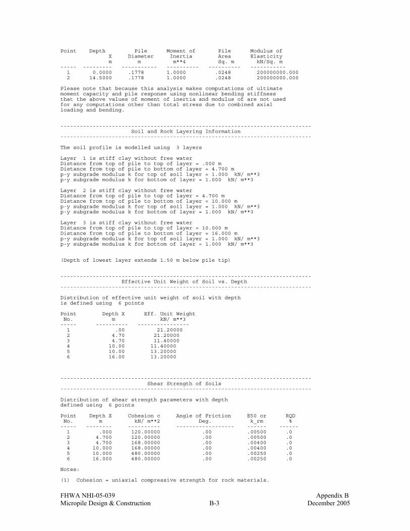
FHWA NHI-05-039 Appendix B Micropile Design & Construction B-3 December 2005
Point Depth Pile Moment of Pile Modulus of X Diameter Inertia Area Elasticity m m m**4 Sq. m kN/Sq. m ----- --------- ----------- ---------- ---------- ----------- 1 0.0000 .1778 1.0000 .0248 200000000.000 2 14.5000 .1778 1.0000 .0248 200000000.000 Please note that because this analysis makes computations of ultimate moment capacity and pile response using nonlinear bending stiffness that the above values of moment of inertia and modulus of are not used for any computations other than total stress due to combined axial loading and bending. ------------------------------------------------------------------------------ Soil and Rock Layering Information ------------------------------------------------------------------------------ The soil profile is modelled using 3 layers Layer 1 is stiff clay without free water Distance from top of pile to top of layer = .000 m Distance from top of pile to bottom of layer = 4.700 m p-y subgrade modulus k for top of soil layer = 1.000 kN/ m**3 p-y subgrade modulus k for bottom of layer = 1.000 kN/ m**3 Layer 2 is stiff clay without free water Distance from top of pile to top of layer = 4.700 m Distance from top of pile to bottom of layer = 10.000 m p-y subgrade modulus k for top of soil layer = 1.000 kN/ m**3 p-y subgrade modulus k for bottom of layer = 1.000 kN/ m**3 Layer 3 is stiff clay without free water Distance from top of pile to top of layer = 10.000 m Distance from top of pile to bottom of layer = 16.000 m p-y subgrade modulus k for top of soil layer = 1.000 kN/ m**3 p-y subgrade modulus k for bottom of layer = 1.000 kN/ m**3 (Depth of lowest layer extends 1.50 m below pile tip) ------------------------------------------------------------------------------ Effective Unit Weight of Soil vs. Depth ------------------------------------------------------------------------------ Distribution of effective unit weight of soil with depth is defined using 6 points Point Depth X Eff. Unit Weight No. m kN/ m**3 ----- ---------- ---------------- 1 .00 21.20000 2 4.70 21.20000 3 4.70 11.40000 4 10.00 11.40000 5 10.00 13.20000 6 16.00 13.20000 ------------------------------------------------------------------------------ Shear Strength of Soils ------------------------------------------------------------------------------ Distribution of shear strength parameters with depth defined using 6 points Point Depth X Cohesion c Angle of Friction E50 or RQD No. m kN/ m**2 Deg. k_rm % ----- -------- ---------- ------------------ ------ ------ 1 .000 120.00000 .00 .00500 .0 2 4.700 120.00000 .00 .00500 .0 3 4.700 168.00000 .00 .00400 .0 4 10.000 168.00000 .00 .00400 .0 5 10.000 480.00000 .00 .00250 .0 6 16.000 480.00000 .00 .00250 .0 Notes: (1) Cohesion = uniaxial compressive strength for rock materials.

FHWA NHI-05-039 Appendix B Micropile Design & Construction B-4 December 2005
(2) Values of E50 are reported for clay strata. (3) Default values will be generated for E50 when input values are 0. (4) RQD and k_rm are reported only for weak rock strata. ------------------------------------------------------------------------------ p-y Modification Factors ------------------------------------------------------------------------------ Distribution of p-y multipliers with depth defined using 2 points Point Depth X p-mult y-mult No. m ----- ---------- ---------- ---------- 1 .000 1.0000 1.0000 2 .000 1.0000 1.0000 ------------------------------------------------------------------------------ Loading Type ------------------------------------------------------------------------------ Static loading criteria was used for computation of p-y curves ------------------------------------------------------------------------------ Pile-head Loading and Pile-head Fixity Conditions ------------------------------------------------------------------------------ Number of loads specified = 1 Load Case Number 1 Pile-head boundary conditions are Shear and Moment (BC Type 1) Shear force at pile head = .000 kN Bending moment at pile head = .000 m- kN Axial load at pile head = .000 kN (Zero moment at pile head for this load indicates a free-head condition) ------------------------------------------------------------------------------ Output of p-y Curves at Specified Depths ------------------------------------------------------------------------------ p-y curves are generated and printed for verification at 8 depths. Depth Depth Below Pile Head Depth Below Ground Surface No. m m ----- --------------------- -------------------------- 1 .000 .000 2 1.000 1.000 3 2.000 2.000 4 4.690 4.690 5 4.710 4.710 6 9.990 9.990 7 10.010 10.010 8 14.500 14.500 ------------------------------------------------------------------------------ Computations of Ultimate Moment Capacity and Nonlinear Bending Stiffness ------------------------------------------------------------------------------ Pile Description: The sectional shape is a circular shaft with steel casing. Outside Diameter = .1778 m Wall thickness of steel shell = .0115 m Cross-sectional area of shell = .00601 m**2 Moment of inertia of steel shell = 2.08692E-05 m**4 Material Properties: Compressive Strength of Concrete = 27600.000 kN/ m**2 Yield Stress of Reinforcement = 0. kN/ m**2 Steel shell or core yield stress = 552000. kN/ m**2

FHWA NHI-05-039 Appendix B Micropile Design & Construction B-5 December 2005
Modulus of Elasticity of Reinforcement = 200000000. kN/ m**2 Cover Thickness (edge to bar center) = .000 m Number of Reinforcing Bars = 10 Area of Single Bar = .00000 m**2 Number of Rows of Reinforcing Bars = 5 Ultimate Axial Squash Load Capacity = 3758.02 kN Distribution and Area of Steel Reinforcement Row Area of Distance to Number Reinforcement Centroidal Axis m**2 m ------ ------------- --------------- 1 .000000 .0736 2 .000000 .0455 3 .000000 .0000 4 .000000 -.0455 5 .000000 -.0736 Axial Thrust Force = .00 kN Bending Bending Bending Maximum Neutral Axis Moment Stiffness Curvature Strain Position kN-m kN-m2 rad/m m/m m ------------- ------------- ------------- ------------- ------------- 1.73583660 4898.917 .00035433 .00002742 .08889729 2.50651820 4897.351 .00051181 .00003961 .08889729 3.27670667 4895.785 .00066929 .00005180 .08889729 4.04640201 4894.220 .00082677 .00006399 .08889729 4.81560422 4892.654 .00098425 .00007618 .08889729 5.58431330 4891.088 .00114173 .00008837 .08889729 6.35252925 4889.522 .00129921 .00010056 .08889729 6.55060560 4496.902 .00145669 .00010411 .08297207 7.25778201 4496.284 .00161417 .00011537 .08297207 7.96476385 4495.667 .00177165 .00012662 .08297207 8.67155112 4495.049 .00192913 .00013788 .08297207 9.37814382 4494.431 .00208661 .00014913 .08297207 10.085 4493.813 .00224409 .00016039 .08297207 10.791 4493.196 .00240157 .00017165 .08297207 11.497 4492.578 .00255906 .00018290 .08297207 12.203 4491.960 .00271654 .00019416 .08297207 12.908 4491.342 .00287402 .00020541 .08297207 13.614 4490.725 .00303150 .00021667 .08297207 14.319 4490.107 .00318898 .00022792 .08297207 15.024 4489.489 .00334646 .00023918 .08297207 15.729 4488.871 .00350394 .00025043 .08297207 16.433 4488.254 .00366142 .00026169 .08297207 17.138 4487.636 .00381890 .00027294 .08297207 17.842 4487.018 .00397638 .00028420 .08297207 23.118 4482.385 .00515748 .00036862 .08297207 28.383 4477.752 .00633858 .00045303 .08297207 33.636 4473.118 .00751969 .00053745 .08297207 38.879 4468.485 .00870079 .00062186 .08297207 44.111 4463.852 .00988189 .00070628 .08297207 49.332 4459.219 .01106299 .00079069 .08297207 54.542 4454.586 .01224409 .00087511 .08297207 57.662 4295.045 .01342520 .00095982 .08299377 62.752 4296.211 .01460630 .00104577 .08309687 67.845 4297.412 .01578740 .00113196 .08319996 72.947 4298.973 .01696850 .00121848 .08330848 78.054 4300.601 .01814961 .00130527 .08341700 83.173 4302.638 .01933071 .00139241 .08353095 88.306 4305.127 .02051181 .00147993 .08365032 93.456 4308.127 .02169291 .00156786 .08377512 98.635 4312.080 .02287402 .00165633 .08391077 103.850 4317.171 .02405512 .00174537 .08405727 109.135 4324.538 .02523622 .00183532 .08422548 116.274 4401.446 .02641732 .00194228 .08502310 121.355 4397.159 .02759843 .00203107 .08509364 126.423 4392.803 .02877953 .00212002 .08516418 131.480 4388.413 .02996063 .00220914 .08523472
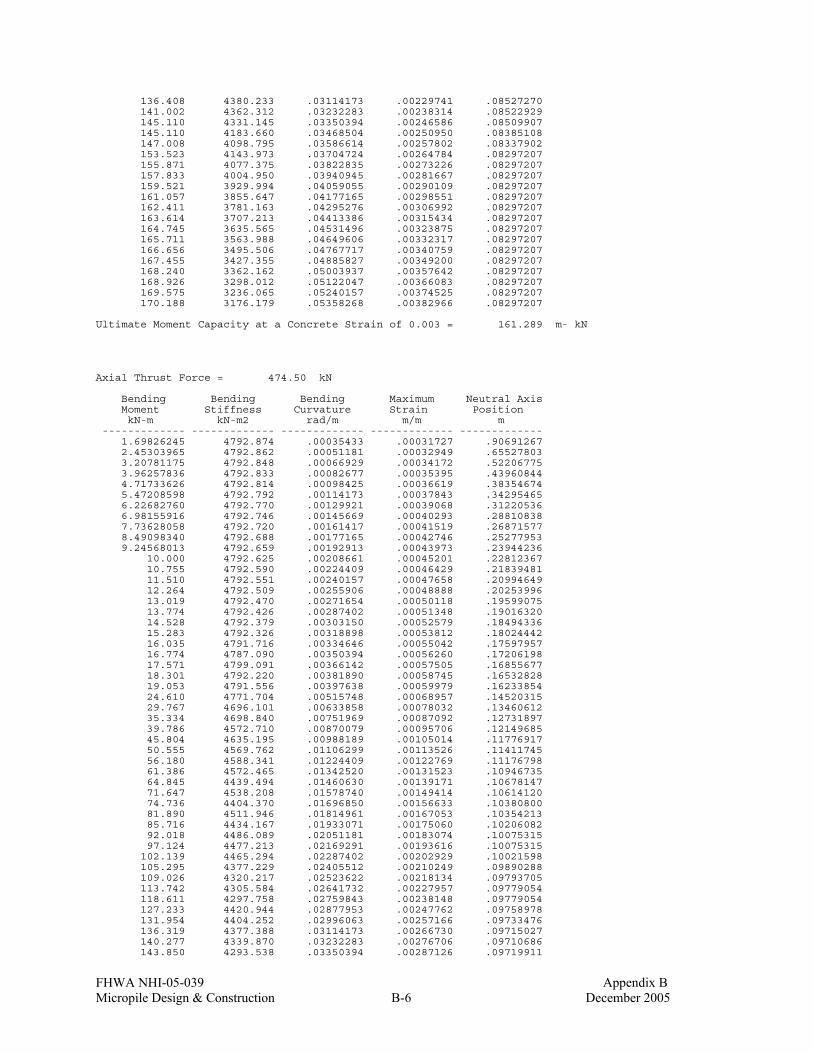
FHWA NHI-05-039 Appendix B Micropile Design & Construction B-6 December 2005
136.408 4380.233 .03114173 .00229741 .08527270 141.002 4362.312 .03232283 .00238314 .08522929 145.110 4331.145 .03350394 .00246586 .08509907 145.110 4183.660 .03468504 .00250950 .08385108 147.008 4098.795 .03586614 .00257802 .08337902 153.523 4143.973 .03704724 .00264784 .08297207 155.871 4077.375 .03822835 .00273226 .08297207 157.833 4004.950 .03940945 .00281667 .08297207 159.521 3929.994 .04059055 .00290109 .08297207 161.057 3855.647 .04177165 .00298551 .08297207 162.411 3781.163 .04295276 .00306992 .08297207 163.614 3707.213 .04413386 .00315434 .08297207 164.745 3635.565 .04531496 .00323875 .08297207 165.711 3563.988 .04649606 .00332317 .08297207 166.656 3495.506 .04767717 .00340759 .08297207 167.455 3427.355 .04885827 .00349200 .08297207 168.240 3362.162 .05003937 .00357642 .08297207 168.926 3298.012 .05122047 .00366083 .08297207 169.575 3236.065 .05240157 .00374525 .08297207 170.188 3176.179 .05358268 .00382966 .08297207 Ultimate Moment Capacity at a Concrete Strain of 0.003 = 161.289 m- kN Axial Thrust Force = 474.50 kN Bending Bending Bending Maximum Neutral Axis Moment Stiffness Curvature Strain Position kN-m kN-m2 rad/m m/m m ------------- ------------- ------------- ------------- ------------- 1.69826245 4792.874 .00035433 .00031727 .90691267 2.45303965 4792.862 .00051181 .00032949 .65527803 3.20781175 4792.848 .00066929 .00034172 .52206775 3.96257836 4792.833 .00082677 .00035395 .43960844 4.71733626 4792.814 .00098425 .00036619 .38354674 5.47208598 4792.792 .00114173 .00037843 .34295465 6.22682760 4792.770 .00129921 .00039068 .31220536 6.98155916 4792.746 .00145669 .00040293 .28810838 7.73628058 4792.720 .00161417 .00041519 .26871577 8.49098340 4792.688 .00177165 .00042746 .25277953 9.24568013 4792.659 .00192913 .00043973 .23944236 10.000 4792.625 .00208661 .00045201 .22812367 10.755 4792.590 .00224409 .00046429 .21839481 11.510 4792.551 .00240157 .00047658 .20994649 12.264 4792.509 .00255906 .00048888 .20253996 13.019 4792.470 .00271654 .00050118 .19599075 13.774 4792.426 .00287402 .00051348 .19016320 14.528 4792.379 .00303150 .00052579 .18494336 15.283 4792.326 .00318898 .00053812 .18024442 16.035 4791.716 .00334646 .00055042 .17597957 16.774 4787.090 .00350394 .00056260 .17206198 17.571 4799.091 .00366142 .00057505 .16855677 18.301 4792.220 .00381890 .00058745 .16532828 19.053 4791.556 .00397638 .00059979 .16233854 24.610 4771.704 .00515748 .00068957 .14520315 29.767 4696.101 .00633858 .00078032 .13460612 35.334 4698.840 .00751969 .00087092 .12731897 39.786 4572.710 .00870079 .00095706 .12149685 45.804 4635.195 .00988189 .00105014 .11776917 50.555 4569.762 .01106299 .00113526 .11411745 56.180 4588.341 .01224409 .00122769 .11176798 61.386 4572.465 .01342520 .00131523 .10946735 64.845 4439.494 .01460630 .00139171 .10678147 71.647 4538.208 .01578740 .00149414 .10614120 74.736 4404.370 .01696850 .00156633 .10380800 81.890 4511.946 .01814961 .00167053 .10354213 85.716 4434.167 .01933071 .00175060 .10206082 92.018 4486.089 .02051181 .00183074 .10075315 97.124 4477.213 .02169291 .00193616 .10075315 102.139 4465.294 .02287402 .00202929 .10021598 105.295 4377.229 .02405512 .00210249 .09890288 109.026 4320.217 .02523622 .00218134 .09793705 113.742 4305.584 .02641732 .00227957 .09779054 118.611 4297.758 .02759843 .00238148 .09779054 127.233 4420.944 .02877953 .00247762 .09758978 131.954 4404.252 .02996063 .00257166 .09733476 136.319 4377.388 .03114173 .00266730 .09715027 140.277 4339.870 .03232283 .00276706 .09710686 143.850 4293.538 .03350394 .00287126 .09719911

FHWA NHI-05-039 Appendix B Micropile Design & Construction B-7 December 2005
147.136 4242.066 .03468504 .00297869 .09737816 150.123 4185.651 .03586614 .00308557 .09753009 152.748 4123.053 .03704724 .00319502 .09774171 152.748 3995.667 .03822835 .00329874 .09779054 152.748 3875.917 .03940945 .00340066 .09779054 154.387 3803.521 .04059055 .00350258 .09779054 155.966 3733.787 .04177165 .00360450 .09779054 157.340 3663.103 .04295276 .00370642 .09779054 158.551 3592.498 .04413386 .00380833 .09779054 Ultimate Moment Capacity at a Concrete Strain of 0.003 = 147.732 m- kN p-y Curve Computed Using Criteria for Stiff Clay without Free Water Soil Layer Number = 1 Depth below pile head = .000 m Depth below ground surface = .000 m Equivalent Depth = .000 m Diameter = .178 m Undrained cohesion, c = 120.00000 kN/ m**2 Avg. Undrained cohesion, c = 120.00000 kN/ m**2 Average Eff. Unit Weight = 21.20000 kN/ m**3 Epsilon-50 = .00500 Pct = 64.008 kN/ m Pcd = 192.024 kN/ m y50 = .002 m p-multiplier = 1.00000 y-multiplier = 1.00000 y, m p, kN/ m ---------------- ----------------- .0000 .000 .0000 3.599 .0000 5.382 .0000 6.401 .0000 9.571 .0000 11.382 .0002 17.021 .0004 20.241 .0009 25.452 .0018 30.268 .0027 33.497 .0036 35.994 .0089 45.260 .0178 53.824 .0356 64.008 .0400 64.008 .0445 64.008 p-y Curve Computed Using Criteria for Stiff Clay without Free Water Soil Layer Number = 1 Depth below pile head = 1.000 m Depth below ground surface = 1.000 m Equivalent Depth = 1.000 m Diameter = .178 m Undrained cohesion, c = 120.00000 kN/ m**2 Avg. Undrained cohesion, c = 120.00000 kN/ m**2 Average Eff. Unit Weight = 21.20000 kN/ m**3 Epsilon-50 = .00500 Pct = 127.777 kN/ m Pcd = 192.024 kN/ m y50 = .002 m p-multiplier = 1.00000 y-multiplier = 1.00000 y, m p, kN/ m ---------------- ----------------- .0000 .000 .0000 7.185 .0000 10.745 .0000 12.778 .0000 19.107 .0000 22.722 .0002 33.978 .0004 40.407 .0009 50.809 .0018 60.422 .0027 66.868 .0036 71.854 .0089 90.352

FHWA NHI-05-039 Appendix B Micropile Design & Construction B-8 December 2005
.0178 107.448 .0356 127.777 .0400 127.777 .0445 127.777 p-y Curve Computed Using Criteria for Stiff Clay without Free Water Soil Layer Number = 1 Depth below pile head = 2.000 m Depth below ground surface = 2.000 m Equivalent Depth = 2.000 m Diameter = .178 m Undrained cohesion, c = 120.00000 kN/ m**2 Avg. Undrained cohesion, c = 120.00000 kN/ m**2 Average Eff. Unit Weight = 21.20000 kN/ m**3 Epsilon-50 = .00500 Pct = 191.547 kN/ m Pcd = 192.024 kN/ m y50 = .002 m p-multiplier = 1.00000 y-multiplier = 1.00000 y, m p, kN/ m ---------------- ----------------- .0000 .000 .0000 10.771 .0000 16.107 .0000 19.155 .0000 28.643 .0000 34.062 .0002 50.935 .0004 60.572 .0009 76.166 .0018 90.577 .0027 100.240 .0036 107.715 .0089 135.444 .0178 161.071 .0356 191.547 .0400 191.547 .0445 191.547 p-y Curve Computed Using Criteria for Stiff Clay without Free Water Soil Layer Number = 1 Depth below pile head = 4.690 m Depth below ground surface = 4.690 m Equivalent Depth = 4.690 m Diameter = .178 m Undrained cohesion, c = 120.00000 kN/ m**2 Avg. Undrained cohesion, c = 120.00000 kN/ m**2 Average Eff. Unit Weight = 21.20000 kN/ m**3 Epsilon-50 = .00500 Pct = 363.086 kN/ m Pcd = 192.024 kN/ m y50 = .002 m p-multiplier = 1.00000 y-multiplier = 1.00000 y, m p, kN/ m ---------------- ----------------- .0000 .000 .0000 10.798 .0000 16.147 .0000 19.202 .0000 28.714 .0000 34.147 .0002 51.062 .0004 60.723 .0009 76.356 .0018 90.803 .0027 100.490 .0036 107.983 .0089 135.781 .0178 161.472 .0356 192.024 .0400 192.024 .0445 192.024

FHWA NHI-05-039 Appendix B Micropile Design & Construction B-9 December 2005
p-y Curve Computed Using Criteria for Stiff Clay without Free Water Soil Layer Number = 2 Depth below pile head = 4.710 m Depth below ground surface = 4.710 m Equivalent Depth = 4.710 m Diameter = .178 m Undrained cohesion, c = 168.00000 kN/ m**2 Avg. Undrained cohesion, c = 168.00000 kN/ m**2 Average Eff. Unit Weight = 21.17919 kN/ m**3 Epsilon-50 = .00400 Pct = 502.977 kN/ m Pcd = 268.834 kN/ m y50 = .002 m p-multiplier = 1.00000 y-multiplier = 1.00000 y, m p, kN/ m ---------------- ----------------- .0000 .000 .0000 15.118 .0000 22.606 .0000 26.883 .0000 40.200 .0000 47.806 .0001 71.487 .0003 85.013 .0007 106.898 .0014 127.124 .0021 140.685 .0028 151.176 .0071 190.094 .0142 226.061 .0284 268.834 .0320 268.834 .0356 268.834 p-y Curve Computed Using Criteria for Stiff Clay without Free Water Soil Layer Number = 2 Depth below pile head = 9.990 m Depth below ground surface = 9.990 m Equivalent Depth = 9.990 m Diameter = .178 m Undrained cohesion, c = 168.00000 kN/ m**2 Avg. Undrained cohesion, c = 168.00000 kN/ m**2 Average Eff. Unit Weight = 16.01061 kN/ m**3 Epsilon-50 = .00400 Pct = 957.200 kN/ m Pcd = 268.834 kN/ m y50 = .002 m p-multiplier = 1.00000 y-multiplier = 1.00000 y, m p, kN/ m ---------------- ----------------- .0000 .000 .0000 15.118 .0000 22.606 .0000 26.883 .0000 40.200 .0000 47.806 .0001 71.487 .0003 85.013 .0007 106.898 .0014 127.124 .0021 140.685 .0028 151.176 .0071 190.094 .0142 226.061 .0284 268.834 .0320 268.834 .0356 268.834 p-y Curve Computed Using Criteria for Stiff Clay without Free Water
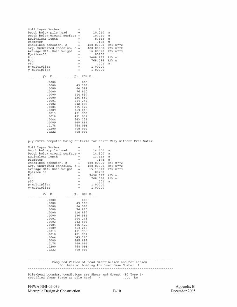
FHWA NHI-05-039 Appendix B Micropile Design & Construction B-10 December 2005
Soil Layer Number = 3 Depth below pile head = 10.010 m Depth below ground surface = 10.010 m Equivalent Depth = 8.863 m Diameter = .178 m Undrained cohesion, c = 480.00000 kN/ m**2 Avg. Undrained cohesion, c = 480.00000 kN/ m**2 Average Eff. Unit Weight = 16.00320 kN/ m**3 Epsilon-50 = .00250 Pct = 2408.297 kN/ m Pcd = 768.096 kN/ m y50 = .001 m p-multiplier = 1.00000 y-multiplier = 1.00000 y, m p, kN/ m ---------------- ----------------- .0000 .000 .0000 43.193 .0000 64.589 .0000 76.810 .0000 114.857 .0000 136.589 .0001 204.248 .0002 242.893 .0004 305.422 .0009 363.210 .0013 401.958 .0018 431.932 .0044 543.126 .0089 645.889 .0178 768.096 .0200 768.096 .0222 768.096 p-y Curve Computed Using Criteria for Stiff Clay without Free Water Soil Layer Number = 3 Depth below pile head = 14.500 m Depth below ground surface = 14.500 m Equivalent Depth = 13.353 m Diameter = .178 m Undrained cohesion, c = 480.00000 kN/ m**2 Avg. Undrained cohesion, c = 480.00000 kN/ m**2 Average Eff. Unit Weight = 15.13517 kN/ m**3 Epsilon-50 = .00250 Pct = 3496.612 kN/ m Pcd = 768.096 kN/ m y50 = .001 m p-multiplier = 1.00000 y-multiplier = 1.00000 y, m p, kN/ m ---------------- ----------------- .0000 .000 .0000 43.193 .0000 64.589 .0000 76.810 .0000 114.857 .0000 136.589 .0001 204.248 .0002 242.893 .0004 305.422 .0009 363.210 .0013 401.958 .0018 431.932 .0044 543.126 .0089 645.889 .0178 768.096 .0200 768.096 .0222 768.096 ------------------------------------------------------------------------------ Computed Values of Load Distribution and Deflection for Lateral Loading for Load Case Number 1 ------------------------------------------------------------------------------ Pile-head boundary conditions are Shear and Moment (BC Type 1) Specified shear force at pile head = .000 kN

FHWA NHI-05-039 Appendix B Micropile Design & Construction B-11 December 2005
Specified bending moment at pile head = .000 m- kN Specified axial load at pile head = .000 kN (Zero moment for this load indicates free-head conditions) Depth Deflect. Moment Shear Slope Total Flx. Rig. Soil Res X y M V S Stress EI p m m kN- m kN Rad. kN/ m**2 kN- m**2 kN/ m -------- --------- --------- --------- --------- --------- --------- --------- 0.000 0.000 0.0 0.0 0.000 0.0 4898.917 0.000 .10000 0.000 0.0 0.0 0.000 0.0 4898.917 0.000 .200 0.000 0.0 0.0 0.000 0.0 4898.917 0.000 .300 0.000 0.0 0.0 0.000 0.0 4898.917 0.000 .400 0.000 0.0 0.0 0.000 0.0 4898.917 0.000 .500 0.000 0.0 0.0 0.000 0.0 4898.917 0.000 .600 0.000 0.0 0.0 0.000 0.0 4898.917 0.000 .700 0.000 0.0 0.0 0.000 0.0 4898.917 0.000 .800 0.000 0.0 0.0 0.000 0.0 4898.917 0.000 .900 0.000 0.0 0.0 0.000 0.0 4898.917 0.000 1.000 0.000 0.0 0.0 0.000 0.0 4898.917 0.000 1.100 0.000 0.0 0.0 0.000 0.0 4898.917 0.000 1.200 0.000 0.0 0.0 0.000 0.0 4898.917 0.000 1.300 0.000 0.0 0.0 0.000 0.0 4898.917 0.000 1.400 0.000 0.0 0.0 0.000 0.0 4898.917 0.000 1.500 0.000 0.0 0.0 0.000 0.0 4898.917 0.000 1.600 0.000 0.0 0.0 0.000 0.0 4898.917 0.000 1.700 0.000 0.0 0.0 0.000 0.0 4898.917 0.000 1.800 0.000 0.0 0.0 0.000 0.0 4898.917 0.000 1.900 0.000 0.0 0.0 0.000 0.0 4898.917 0.000 2.000 0.000 0.0 0.0 0.000 0.0 4898.917 0.000 2.100 0.000 0.0 0.0 0.000 0.0 4898.917 0.000 2.200 0.000 0.0 0.0 0.000 0.0 4898.917 0.000 2.300 0.000 0.0 0.0 0.000 0.0 4898.917 0.000 2.400 0.000 0.0 0.0 0.000 0.0 4898.917 0.000 2.500 0.000 0.0 0.0 0.000 0.0 4898.917 0.000 2.600 0.000 0.0 0.0 0.000 0.0 4898.917 0.000 2.700 0.000 0.0 0.0 0.000 0.0 4898.917 0.000 2.800 0.000 0.0 0.0 0.000 0.0 4898.917 0.000 2.900 0.000 0.0 0.0 0.000 0.0 4898.917 0.000 3.000 0.000 0.0 0.0 0.000 0.0 4898.917 0.000 3.100 0.000 0.0 0.0 0.000 0.0 4898.917 0.000 3.200 0.000 0.0 0.0 0.000 0.0 4898.917 0.000 3.300 0.000 0.0 0.0 0.000 0.0 4898.917 0.000 3.400 0.000 0.0 0.0 0.000 0.0 4898.917 0.000 3.500 0.000 0.0 0.0 0.000 0.0 4898.917 0.000 3.600 0.000 0.0 0.0 0.000 0.0 4898.917 0.000 3.700 0.000 0.0 0.0 0.000 0.0 4898.917 0.000 3.800 0.000 0.0 0.0 0.000 0.0 4898.917 0.000 3.900 0.000 0.0 0.0 0.000 0.0 4898.917 0.000 4.000 0.000 0.0 0.0 0.000 0.0 4898.917 0.000 4.100 0.000 0.0 0.0 0.000 0.0 4898.917 0.000 4.200 0.000 0.0 0.0 0.000 0.0 4898.917 0.000 4.300 0.000 0.0 0.0 0.000 0.0 4898.917 0.000 4.400 0.000 0.0 0.0 0.000 0.0 4898.917 0.000 4.500 0.000 0.0 0.0 0.000 0.0 4898.917 0.000 4.600 0.000 0.0 0.0 0.000 0.0 4898.917 0.000 4.700 0.000 0.0 0.0 0.000 0.0 4898.917 0.000 4.800 0.000 0.0 0.0 0.000 0.0 4898.917 0.000 4.900 0.000 0.0 0.0 0.000 0.0 4898.917 0.000 5.000 0.000 0.0 0.0 0.000 0.0 4898.917 0.000 5.100 0.000 0.0 0.0 0.000 0.0 4898.917 0.000 5.200 0.000 0.0 0.0 0.000 0.0 4898.917 0.000 5.300 0.000 0.0 0.0 0.000 0.0 4898.917 0.000 5.400 0.000 0.0 0.0 0.000 0.0 4898.917 0.000 5.500 0.000 0.0 0.0 0.000 0.0 4898.917 0.000 5.600 0.000 0.0 0.0 0.000 0.0 4898.917 0.000 5.700 0.000 0.0 0.0 0.000 0.0 4898.917 0.000 5.800 0.000 0.0 0.0 0.000 0.0 4898.917 0.000 5.900 0.000 0.0 0.0 0.000 0.0 4898.917 0.000 6.000 0.000 0.0 0.0 0.000 0.0 4898.917 0.000 6.100 0.000 0.0 0.0 0.000 0.0 4898.917 0.000 6.200 0.000 0.0 0.0 0.000 0.0 4898.917 0.000 6.300 0.000 0.0 0.0 0.000 0.0 4898.917 0.000 6.400 0.000 0.0 0.0 0.000 0.0 4898.917 0.000 6.500 0.000 0.0 0.0 0.000 0.0 4898.917 0.000 6.600 0.000 0.0 0.0 0.000 0.0 4898.917 0.000 6.700 0.000 0.0 0.0 0.000 0.0 4898.917 0.000 6.800 0.000 0.0 0.0 0.000 0.0 4898.917 0.000 6.900 0.000 0.0 0.0 0.000 0.0 4898.917 0.000 7.000 0.000 0.0 0.0 0.000 0.0 4898.917 0.000 7.100 0.000 0.0 0.0 0.000 0.0 4898.917 0.000

FHWA NHI-05-039 Appendix B Micropile Design & Construction B-12 December 2005
7.200 0.000 0.0 0.0 0.000 0.0 4898.917 0.000 7.300 0.000 0.0 0.0 0.000 0.0 4898.917 0.000 7.400 0.000 0.0 0.0 0.000 0.0 4898.917 0.000 7.500 0.000 0.0 0.0 0.000 0.0 4898.917 0.000 7.600 0.000 0.0 0.0 0.000 0.0 4898.917 0.000 7.700 0.000 0.0 0.0 0.000 0.0 4898.917 0.000 7.800 0.000 0.0 0.0 0.000 0.0 4898.917 0.000 7.900 0.000 0.0 0.0 0.000 0.0 4898.917 0.000 8.000 0.000 0.0 0.0 0.000 0.0 4898.917 0.000 8.100 0.000 0.0 0.0 0.000 0.0 4898.917 0.000 8.200 0.000 0.0 0.0 0.000 0.0 4898.917 0.000 8.300 0.000 0.0 0.0 0.000 0.0 4898.917 0.000 8.400 0.000 0.0 0.0 0.000 0.0 4898.917 0.000 8.500 0.000 0.0 0.0 0.000 0.0 4898.917 0.000 8.600 0.000 0.0 0.0 0.000 0.0 4898.917 0.000 8.700 0.000 0.0 0.0 0.000 0.0 4898.917 0.000 8.800 0.000 0.0 0.0 0.000 0.0 4898.917 0.000 8.900 0.000 0.0 0.0 0.000 0.0 4898.917 0.000 9.000 0.000 0.0 0.0 0.000 0.0 4898.917 0.000 9.100 0.000 0.0 0.0 0.000 0.0 4898.917 0.000 9.200 0.000 0.0 0.0 0.000 0.0 4898.917 0.000 9.300 0.000 0.0 0.0 0.000 0.0 4898.917 0.000 9.400 0.000 0.0 0.0 0.000 0.0 4898.917 0.000 9.500 0.000 0.0 0.0 0.000 0.0 4898.917 0.000 9.600 0.000 0.0 0.0 0.000 0.0 4898.917 0.000 9.700 0.000 0.0 0.0 0.000 0.0 4898.917 0.000 9.800 0.000 0.0 0.0 0.000 0.0 4898.917 0.000 9.900 0.000 0.0 0.0 0.000 0.0 4898.917 0.000 10.000 0.000 0.0 0.0 0.000 0.0 4898.917 0.000 10.100 0.000 0.0 0.0 0.000 0.0 4898.917 0.000 10.200 0.000 0.0 0.0 0.000 0.0 4898.917 0.000 10.300 0.000 0.0 0.0 0.000 0.0 4898.917 0.000 10.400 0.000 0.0 0.0 0.000 0.0 4898.917 0.000 10.500 0.000 0.0 0.0 0.000 0.0 4898.917 0.000 10.600 0.000 0.0 0.0 0.000 0.0 4898.917 0.000 10.700 0.000 0.0 0.0 0.000 0.0 4898.917 0.000 10.800 0.000 0.0 0.0 0.000 0.0 4898.917 0.000 10.900 0.000 0.0 0.0 0.000 0.0 4898.917 0.000 11.000 0.000 0.0 0.0 0.000 0.0 4898.917 0.000 11.100 0.000 0.0 0.0 0.000 0.0 4898.917 0.000 11.200 0.000 0.0 0.0 0.000 0.0 4898.917 0.000 11.300 0.000 0.0 0.0 0.000 0.0 4898.917 0.000 11.400 0.000 0.0 0.0 0.000 0.0 4898.917 0.000 11.500 0.000 0.0 0.0 0.000 0.0 4898.917 0.000 11.600 0.000 0.0 0.0 0.000 0.0 4898.917 0.000 11.700 0.000 0.0 0.0 0.000 0.0 4898.917 0.000 11.800 0.000 0.0 0.0 0.000 0.0 4898.917 0.000 11.900 0.000 0.0 0.0 0.000 0.0 4898.917 0.000 12.000 0.000 0.0 0.0 0.000 0.0 4898.917 0.000 12.100 0.000 0.0 0.0 0.000 0.0 4898.917 0.000 12.200 0.000 0.0 0.0 0.000 0.0 4898.917 0.000 12.300 0.000 0.0 0.0 0.000 0.0 4898.917 0.000 12.400 0.000 0.0 0.0 0.000 0.0 4898.917 0.000 12.500 0.000 0.0 0.0 0.000 0.0 4898.917 0.000 12.600 0.000 0.0 0.0 0.000 0.0 4898.917 0.000 12.700 0.000 0.0 0.0 0.000 0.0 4898.917 0.000 12.800 0.000 0.0 0.0 0.000 0.0 4898.917 0.000 12.900 0.000 0.0 0.0 0.000 0.0 4898.917 0.000 13.000 0.000 0.0 0.0 0.000 0.0 4898.917 0.000 13.100 0.000 0.0 0.0 0.000 0.0 4898.917 0.000 13.200 0.000 0.0 0.0 0.000 0.0 4898.917 0.000 13.300 0.000 0.0 0.0 0.000 0.0 4898.917 0.000 13.400 0.000 0.0 0.0 0.000 0.0 4898.917 0.000 13.500 0.000 0.0 0.0 0.000 0.0 4898.917 0.000 13.600 0.000 0.0 0.0 0.000 0.0 4898.917 0.000 13.700 0.000 0.0 0.0 0.000 0.0 4898.917 0.000 13.800 0.000 0.0 0.0 0.000 0.0 4898.917 0.000 13.900 0.000 0.0 0.0 0.000 0.0 4898.917 0.000 14.000 0.000 0.0 0.0 0.000 0.0 4898.917 0.000 14.100 0.000 0.0 0.0 0.000 0.0 4898.917 0.000 14.200 0.000 0.0 0.0 0.000 0.0 4898.917 0.000 14.300 0.000 0.0 0.0 0.000 0.0 4898.917 0.000 14.400 0.000 0.0 0.0 0.000 0.0 4898.917 0.000 14.500 0.000 0.0 0.0 0.000 0.0 4898.917 0.000 Please note that because this analysis makes computations of ultimate moment capacity and pile response using nonlinear bending stiffness that the above values of total stress due to combined axial stress and bending may not be representative of actual conditions.

FHWA NHI-05-039 Appendix B Micropile Design & Construction B-13 December 2005
Output Verification: Computed forces and moments are within specified convergence limits. Output Summary for Load Case No. 1: Pile-head deflection = 0.000 m Computed slope at pile head = 0.000 Maximum bending moment = 0.000 kN- m Maximum shear force = 0.000 kN Depth of maximum bending moment = 0.000 m Depth of maximum shear force = 0.000 m Number of iterations = 5 Number of zero deflection points = 0
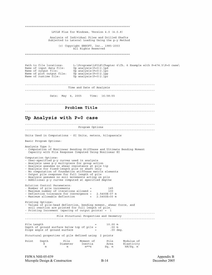
FHWA NHI-05-039 Appendix B Micropile Design & Construction B-14 December 2005
=============================================================== LPILE Plus for Windows, Version 4.0 (4.0.8) Analysis of Individual Piles and Drilled Shafts Subjected to Lateral Loading Using the p-y Method (c) Copyright ENSOFT, Inc., 1985-2003 All Rights Reserved =============================================================== Path to file locations: L:\Programs\LPILE\Chapter 6\Ch. 6 Example with P=474.5\P=0 case\ Name of input data file: Up analysis(P=0)2.lpd Name of output file: Up analysis(P=0)2.lpo Name of plot output file: Up analysis(P=0)2.lpp Name of runtime file: Up analysis(P=0)2.lpr ------------------------------------------------------------------------------ Time and Date of Analysis ------------------------------------------------------------------------------ Date: May 4, 2005 Time: 16:58:55 ------------------------------------------------------------------------------
Problem Title ------------------------------------------------------------------------------
Up Analysis with P=0 case ------------------------------------------------------------------------------ Program Options ------------------------------------------------------------------------------ Units Used in Computations - SI Units, meters, kilopascals Basic Program Options: Analysis Type 3: - Computation of Nonlinear Bending Stiffness and Ultimate Bending Moment Capacity with Pile Response Computed Using Nonlinear EI Computation Options: - User-specified p-y curves used in analysis - Analysis uses p-y multiplers for group action - Analysis assumes no shear resistance at pile tip - Analysis for fixed-length pile or shaft only - No computation of foundation stiffness matrix elements - Output pile response for full length of pile - Analysis assumes no soil movements acting on pile - Additional p-y curves computed at specified depths Solution Control Parameters: - Number of pile increments = 145 - Maximum number of iterations allowed = 100 - Deflection tolerance for convergence = 2.5400E-07 m - Maximum allowable deflection = 2.5400E+00 m Printing Options: - Values of pile-head deflection, bending moment, shear force, and soil reaction are printed for full length of pile. - Printing Increment (spacing of output points) = 1 ------------------------------------------------------------------------------ Pile Structural Properties and Geometry ------------------------------------------------------------------------------ Pile Length = 10.00 m Depth of ground surface below top of pile = .00 m Slope angle of ground surface = .00 deg. Structural properties of pile defined using 2 points Point Depth Pile Moment of Pile Modulus of X Diameter Inertia Area Elasticity m m m**4 Sq. m kN/Sq. m
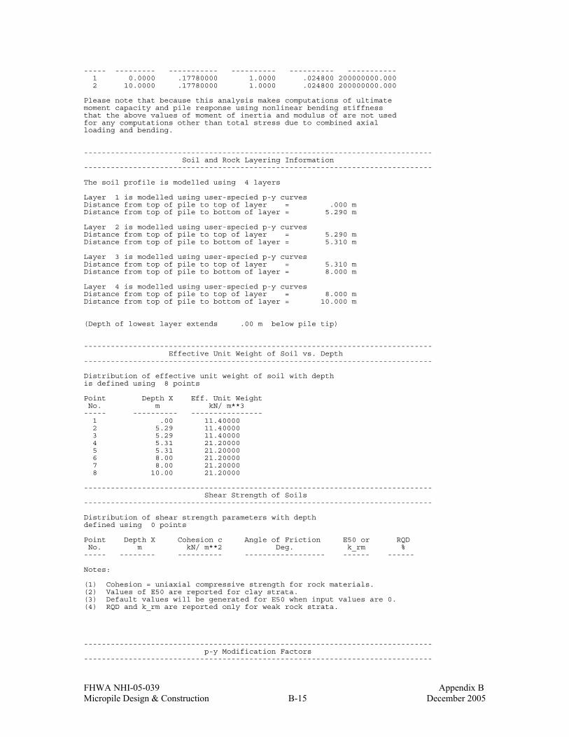
FHWA NHI-05-039 Appendix B Micropile Design & Construction B-15 December 2005
----- --------- ----------- ---------- ---------- ----------- 1 0.0000 .17780000 1.0000 .024800 200000000.000 2 10.0000 .17780000 1.0000 .024800 200000000.000 Please note that because this analysis makes computations of ultimate moment capacity and pile response using nonlinear bending stiffness that the above values of moment of inertia and modulus of are not used for any computations other than total stress due to combined axial loading and bending. ------------------------------------------------------------------------------ Soil and Rock Layering Information ------------------------------------------------------------------------------ The soil profile is modelled using 4 layers Layer 1 is modelled using user-specied p-y curves Distance from top of pile to top of layer = .000 m Distance from top of pile to bottom of layer = 5.290 m Layer 2 is modelled using user-specied p-y curves Distance from top of pile to top of layer = 5.290 m Distance from top of pile to bottom of layer = 5.310 m Layer 3 is modelled using user-specied p-y curves Distance from top of pile to top of layer = 5.310 m Distance from top of pile to bottom of layer = 8.000 m Layer 4 is modelled using user-specied p-y curves Distance from top of pile to top of layer = 8.000 m Distance from top of pile to bottom of layer = 10.000 m (Depth of lowest layer extends .00 m below pile tip) ------------------------------------------------------------------------------ Effective Unit Weight of Soil vs. Depth ------------------------------------------------------------------------------ Distribution of effective unit weight of soil with depth is defined using 8 points Point Depth X Eff. Unit Weight No. m kN/ m**3 ----- ---------- ---------------- 1 .00 11.40000 2 5.29 11.40000 3 5.29 11.40000 4 5.31 21.20000 5 5.31 21.20000 6 8.00 21.20000 7 8.00 21.20000 8 10.00 21.20000 ------------------------------------------------------------------------------ Shear Strength of Soils ------------------------------------------------------------------------------ Distribution of shear strength parameters with depth defined using 0 points Point Depth X Cohesion c Angle of Friction E50 or RQD No. m kN/ m**2 Deg. k_rm % ----- -------- ---------- ------------------ ------ ------ Notes: (1) Cohesion = uniaxial compressive strength for rock materials. (2) Values of E50 are reported for clay strata. (3) Default values will be generated for E50 when input values are 0. (4) RQD and k_rm are reported only for weak rock strata. ------------------------------------------------------------------------------ p-y Modification Factors ------------------------------------------------------------------------------
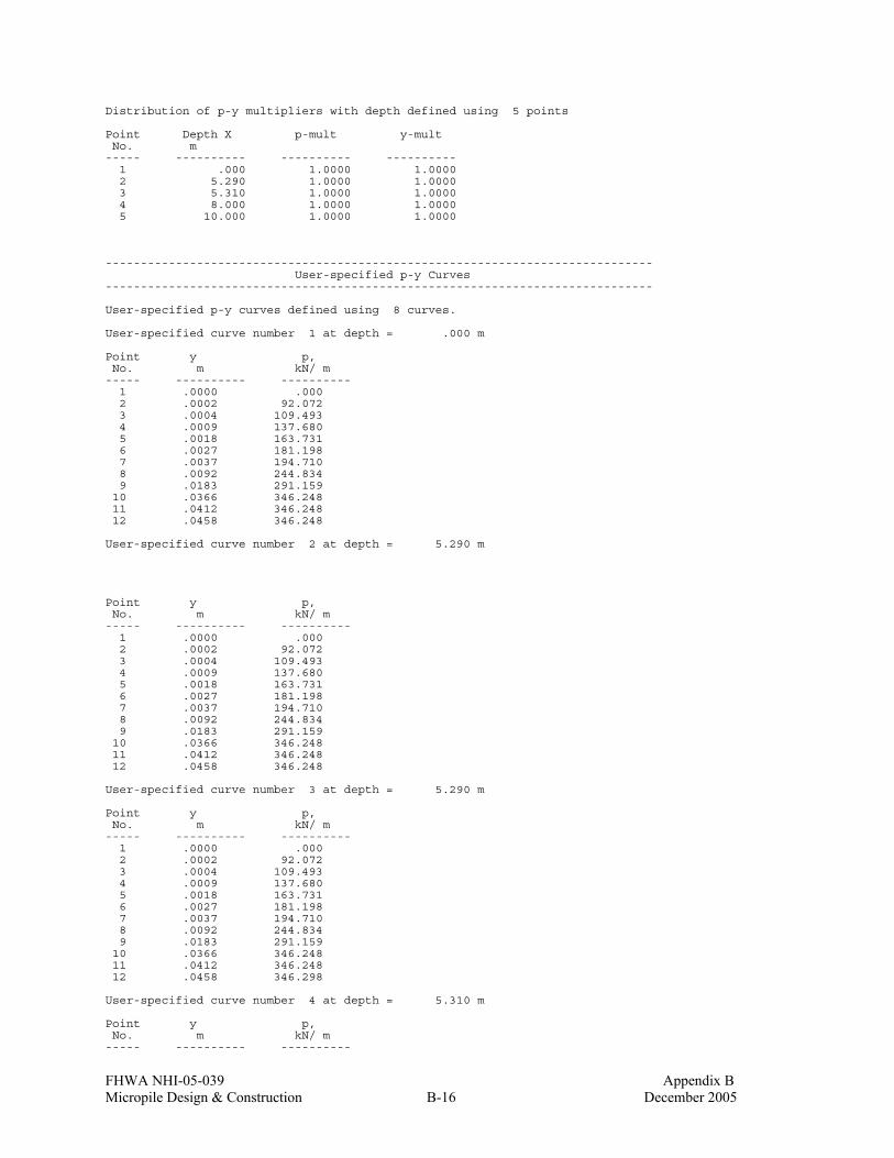
FHWA NHI-05-039 Appendix B Micropile Design & Construction B-16 December 2005
Distribution of p-y multipliers with depth defined using 5 points Point Depth X p-mult y-mult No. m ----- ---------- ---------- ---------- 1 .000 1.0000 1.0000 2 5.290 1.0000 1.0000 3 5.310 1.0000 1.0000 4 8.000 1.0000 1.0000 5 10.000 1.0000 1.0000 ------------------------------------------------------------------------------ User-specified p-y Curves ------------------------------------------------------------------------------ User-specified p-y curves defined using 8 curves. User-specified curve number 1 at depth = .000 m Point y p, No. m kN/ m ----- ---------- ---------- 1 .0000 .000 2 .0002 92.072 3 .0004 109.493 4 .0009 137.680 5 .0018 163.731 6 .0027 181.198 7 .0037 194.710 8 .0092 244.834 9 .0183 291.159 10 .0366 346.248 11 .0412 346.248 12 .0458 346.248 User-specified curve number 2 at depth = 5.290 m Point y p, No. m kN/ m ----- ---------- ---------- 1 .0000 .000 2 .0002 92.072 3 .0004 109.493 4 .0009 137.680 5 .0018 163.731 6 .0027 181.198 7 .0037 194.710 8 .0092 244.834 9 .0183 291.159 10 .0366 346.248 11 .0412 346.248 12 .0458 346.248 User-specified curve number 3 at depth = 5.290 m Point y p, No. m kN/ m ----- ---------- ---------- 1 .0000 .000 2 .0002 92.072 3 .0004 109.493 4 .0009 137.680 5 .0018 163.731 6 .0027 181.198 7 .0037 194.710 8 .0092 244.834 9 .0183 291.159 10 .0366 346.248 11 .0412 346.248 12 .0458 346.298 User-specified curve number 4 at depth = 5.310 m Point y p, No. m kN/ m ----- ---------- ----------

FHWA NHI-05-039 Appendix B Micropile Design & Construction B-17 December 2005
1 .0000 .000 2 .0002 65.766 3 .0005 78.209 4 .0011 98.343 5 .0023 116.950 6 .0034 129.427 7 .0046 139.078 8 .0115 174.882 9 .0229 207.971 10 .0458 247.320 11 .0515 247.320 12 .0573 247.320 User-specified curve number 5 at depth = 5.310 m Point y p, No. m kN/ m ----- ---------- ---------- 1 .0000 .000 2 .0002 65.766 3 .0005 78.209 4 .0011 98.343 5 .0023 116.950 6 .0034 129.427 7 .0046 139.078 8 .0115 174.882 9 .0229 207.971 10 .0458 247.320 11 .0515 247.320 12 .0573 247.320 User-specified curve number 6 at depth = 8.000 m Point y p, No. m kN/ m ----- ---------- ---------- 1 .0000 .000 2 .0002 56.414 3 .0005 67.088 4 .0011 84.358 5 .0023 100.319 6 .0034 111.022 7 .0046 119.300 8 .0115 150.012 9 .0229 178.396 10 .0458 212.150 11 .0515 212.150 12 .0573 212.150 User-specified curve number 7 at depth = 8.000 m Point y p, No. m kN/ m ----- ---------- ---------- 1 .0000 .000 2 .0002 56.414 3 .0005 67.088 4 .0011 84.358 5 .0023 100.319 6 .0034 111.022 7 .0046 119.300 8 .0115 150.012 9 .0229 178.396 10 .0458 212.150 11 .0515 212.150 12 .0573 212.150 User-specified curve number 8 at depth = 10.000 m Point y p, No. m kN/ m ----- ---------- ---------- 1 .0000 .000 2 .0005 26.070 3 .0011 32.781 4 .0020 21.922 5 .0023 38.983 6 .0034 43.142 7 .0046 46.359 8 .0115 58.294 9 .0151 82.440
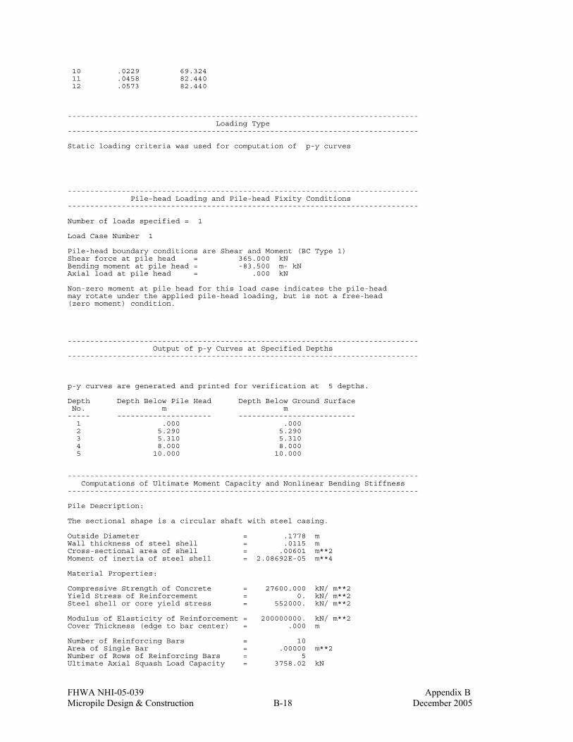
FHWA NHI-05-039 Appendix B Micropile Design & Construction B-18 December 2005
10 .0229 69.324 11 .0458 82.440 12 .0573 82.440 ------------------------------------------------------------------------------ Loading Type ------------------------------------------------------------------------------ Static loading criteria was used for computation of p-y curves ------------------------------------------------------------------------------ Pile-head Loading and Pile-head Fixity Conditions ------------------------------------------------------------------------------ Number of loads specified = 1 Load Case Number 1 Pile-head boundary conditions are Shear and Moment (BC Type 1) Shear force at pile head = 365.000 kN Bending moment at pile head = -83.500 m- kN Axial load at pile head = .000 kN Non-zero moment at pile head for this load case indicates the pile-head may rotate under the applied pile-head loading, but is not a free-head (zero moment) condition. ------------------------------------------------------------------------------ Output of p-y Curves at Specified Depths ------------------------------------------------------------------------------ p-y curves are generated and printed for verification at 5 depths. Depth Depth Below Pile Head Depth Below Ground Surface No. m m ----- --------------------- -------------------------- 1 .000 .000 2 5.290 5.290 3 5.310 5.310 4 8.000 8.000 5 10.000 10.000 ------------------------------------------------------------------------------ Computations of Ultimate Moment Capacity and Nonlinear Bending Stiffness ------------------------------------------------------------------------------ Pile Description: The sectional shape is a circular shaft with steel casing. Outside Diameter = .1778 m Wall thickness of steel shell = .0115 m Cross-sectional area of shell = .00601 m**2 Moment of inertia of steel shell = 2.08692E-05 m**4 Material Properties: Compressive Strength of Concrete = 27600.000 kN/ m**2 Yield Stress of Reinforcement = 0. kN/ m**2 Steel shell or core yield stress = 552000. kN/ m**2 Modulus of Elasticity of Reinforcement = 200000000. kN/ m**2 Cover Thickness (edge to bar center) = .000 m Number of Reinforcing Bars = 10 Area of Single Bar = .00000 m**2 Number of Rows of Reinforcing Bars = 5 Ultimate Axial Squash Load Capacity = 3758.02 kN
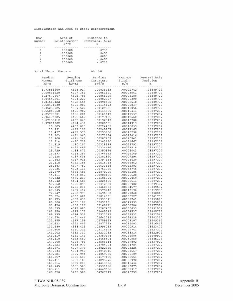
FHWA NHI-05-039 Appendix B Micropile Design & Construction B-19 December 2005
Distribution and Area of Steel Reinforcement Row Area of Distance to Number Reinforcement Centroidal Axis m**2 m ------ ------------- --------------- 1 .000000 .0736 2 .000000 .0455 3 .000000 .0000 4 .000000 -.0455 5 .000000 -.0736 Axial Thrust Force = .00 kN Bending Bending Bending Maximum Neutral Axis Moment Stiffness Curvature Strain Position kN-m kN-m2 rad/m m/m m ------------- ------------- ------------- ------------- ------------- 1.73583660 4898.917 .00035433 .00002742 .08889729 2.50651820 4897.351 .00051181 .00003961 .08889729 3.27670667 4895.785 .00066929 .00005180 .08889729 4.04640201 4894.220 .00082677 .00006399 .08889729 4.81560422 4892.654 .00098425 .00007618 .08889729 5.58431330 4891.088 .00114173 .00008837 .08889729 6.35252925 4889.522 .00129921 .00010056 .08889729 6.55060560 4496.902 .00145669 .00010411 .08297207 7.25778201 4496.284 .00161417 .00011537 .08297207 7.96476385 4495.667 .00177165 .00012662 .08297207 8.67155112 4495.049 .00192913 .00013788 .08297207 9.37814382 4494.431 .00208661 .00014913 .08297207 10.085 4493.813 .00224409 .00016039 .08297207 10.791 4493.196 .00240157 .00017165 .08297207 11.497 4492.578 .00255906 .00018290 .08297207 12.203 4491.960 .00271654 .00019416 .08297207 12.908 4491.342 .00287402 .00020541 .08297207 13.614 4490.725 .00303150 .00021667 .08297207 14.319 4490.107 .00318898 .00022792 .08297207 15.024 4489.489 .00334646 .00023918 .08297207 15.729 4488.871 .00350394 .00025043 .08297207 16.433 4488.254 .00366142 .00026169 .08297207 17.138 4487.636 .00381890 .00027294 .08297207 17.842 4487.018 .00397638 .00028420 .08297207 23.118 4482.385 .00515748 .00036862 .08297207 28.383 4477.752 .00633858 .00045303 .08297207 33.636 4473.118 .00751969 .00053745 .08297207 38.879 4468.485 .00870079 .00062186 .08297207 44.111 4463.852 .00988189 .00070628 .08297207 49.332 4459.219 .01106299 .00079069 .08297207 54.542 4454.586 .01224409 .00087511 .08297207 57.662 4295.045 .01342520 .00095982 .08299377 62.752 4296.211 .01460630 .00104577 .08309687 67.845 4297.412 .01578740 .00113196 .08319996 72.947 4298.973 .01696850 .00121848 .08330848 78.054 4300.601 .01814961 .00130527 .08341700 83.173 4302.638 .01933071 .00139241 .08353095 88.306 4305.127 .02051181 .00147993 .08365032 93.456 4308.127 .02169291 .00156786 .08377512 98.635 4312.080 .02287402 .00165633 .08391077 103.850 4317.171 .02405512 .00174537 .08405727 109.135 4324.538 .02523622 .00183532 .08422548 116.274 4401.446 .02641732 .00194228 .08502310 121.355 4397.159 .02759843 .00203107 .08509364 126.423 4392.803 .02877953 .00212002 .08516418 131.480 4388.413 .02996063 .00220914 .08523472 136.408 4380.233 .03114173 .00229741 .08527270 141.002 4362.312 .03232283 .00238314 .08522929 145.110 4331.145 .03350394 .00246586 .08509907 145.110 4183.660 .03468504 .00250950 .08385108 147.008 4098.795 .03586614 .00257802 .08337902 153.523 4143.973 .03704724 .00264784 .08297207 155.871 4077.375 .03822835 .00273226 .08297207 157.833 4004.950 .03940945 .00281667 .08297207 159.521 3929.994 .04059055 .00290109 .08297207 161.057 3855.647 .04177165 .00298551 .08297207 162.411 3781.163 .04295276 .00306992 .08297207 163.614 3707.213 .04413386 .00315434 .08297207 164.745 3635.565 .04531496 .00323875 .08297207 165.711 3563.988 .04649606 .00332317 .08297207 166.656 3495.506 .04767717 .00340759 .08297207

FHWA NHI-05-039 Appendix B Micropile Design & Construction B-20 December 2005
167.455 3427.355 .04885827 .00349200 .08297207 168.240 3362.162 .05003937 .00357642 .08297207 168.926 3298.012 .05122047 .00366083 .08297207 169.575 3236.065 .05240157 .00374525 .08297207 170.188 3176.179 .05358268 .00382966 .08297207 Ultimate Moment Capacity at a Concrete Strain of 0.003 = 161.289 m- kN p-y Curve Computed by Interpolation from User-input Curves Soil Layer Number = 1 Depth below ground surface = .000 m Depth below pile head = .000 m p-multiplier = 1.00000 y-multiplier = 1.00000 y, m p, kN/ m ---------------- ---------------- .0000 .000 .0010 140.575 .0011 143.795 .0022 171.931 .0033 189.761 .0044 201.500 .0056 211.627 .0067 221.754 .0078 231.882 .0089 242.009 .0100 248.913 .0111 254.570 .0122 260.227 .0133 265.884 .0356 343.117 .0667 346.248 .0889 346.248 p-y Curve Computed by Interpolation from User-input Curves Soil Layer Number = 2 Depth below ground surface = 5.290 m Depth below pile head = 5.290 m p-multiplier = 1.00000 y-multiplier = 1.00000 y, m p, kN/ m ---------------- ---------------- .0000 .000 .0010 140.575 .0011 143.795 .0022 171.931 .0033 189.761 .0044 201.500 .0056 211.627 .0067 221.754 .0078 231.882 .0089 242.009 .0100 248.913 .0111 254.570 .0122 260.227 .0133 265.884 .0356 343.117 .0667 346.248 .0889 346.248 p-y Curve Computed by Interpolation from User-input Curves Soil Layer Number = 3 Depth below ground surface = 5.310 m Depth below pile head = 5.310 m p-multiplier = 1.00000

FHWA NHI-05-039 Appendix B Micropile Design & Construction B-21 December 2005
y-multiplier = 1.00000 y, m p, kN/ m ---------------- ---------------- .0000 .000 .0010 94.987 .0011 98.517 .0022 115.748 .0033 128.676 .0044 137.831 .0056 144.040 .0067 149.806 .0078 155.572 .0089 161.339 .0100 167.105 .0111 172.871 .0122 176.983 .0133 180.208 .0356 229.725 .0667 247.320 .0889 247.320 p-y Curve Computed by Interpolation from User-input Curves Soil Layer Number = 4 Depth below ground surface = 8.000 m Depth below pile head = 8.000 m p-multiplier = 1.00000 y-multiplier = 1.00000 y, m p, kN/ m ---------------- ---------------- .0000 .000 .0010 81.480 .0011 84.508 .0022 99.288 .0033 110.377 .0044 118.231 .0056 123.556 .0067 128.502 .0078 133.449 .0089 138.395 .0100 143.341 .0111 148.287 .0122 151.814 .0133 154.581 .0356 197.057 .0667 212.150 .0889 212.150 p-y Curve Computed by Interpolation from User-input Curves Soil Layer Number = 4 Depth below ground surface = 10.000 m Depth below pile head = 10.000 m p-multiplier = 1.00000 y-multiplier = 1.00000 y, m p, kN/ m ---------------- ---------------- .0000 .000 .0010 31.663 .0011 32.645 .0022 34.576 .0033 42.892 .0044 45.943 .0056 48.013 .0067 49.935 .0078 51.857 .0089 53.779 .0100 55.702 .0111 57.624 .0122 63.148 .0133 70.602 .0356 76.575 .0667 82.440

FHWA NHI-05-039 Appendix B Micropile Design & Construction B-22 December 2005
.0889 82.440 ------------------------------------------------------------------------------ Computed Values of Load Distribution and Deflection for Lateral Loading for Load Case Number 1 ------------------------------------------------------------------------------ Pile-head boundary conditions are Shear and Moment (BC Type 1) Specified shear force at pile head = 365.000 kN Specified bending moment at pile head = -83.500 m- kN Specified axial load at pile head = .000 kN Non-zero moment for this load case indicates the pile-head may rotate under the applied pile-head loading, but is not a free-head (zero moment )condition. Depth Deflect. Moment Shear Slope Total Flx. Rig. Soil Res X y M V S Stress EI p m m kN- m kN Rad. kN/ m**2 kN- m**2 kN/ m -------- --------- --------- --------- --------- --------- --------- --------- 0.000 .047472 -83.5000 365.0 -.035587 7.4232 4295.386 -346.250 .06897 .044972 -59.1510 341.1 -.036732 5.2585 4295.386 -346.250 .138 .042406 -36.4489 317.2 -.037500 3.2403 4295.386 -346.250 .207 .039799 -15.3936 293.4 -.037911 1.3685 4489.165 -346.250 .276 .037177 4.0149 269.5 -.038001 .3569 4894.284 -346.250 .345 .034558 21.7765 245.8 -.037805 1.9359 4483.564 -340.101 .414 .031962 37.9205 222.6 -.037345 3.3711 4469.333 -332.288 .483 .029407 52.4840 200.0 -.036646 4.6658 4456.417 -324.595 .552 .026907 65.5037 177.9 -.035714 5.8233 4296.860 -317.072 .621 .024481 77.0154 156.2 -.034571 6.8467 4300.270 -309.766 .690 .022139 87.0537 135.1 -.033256 7.7391 4304.520 -302.717 .759 .019894 95.6522 114.5 -.031793 8.5035 4309.804 -295.958 .828 .017754 102.8 94.3234 -.030206 9.1427 4316.189 -288.380 .897 .015727 108.7 74.7909 -.028518 9.6601 4323.880 -278.063 .966 .013820 113.2 55.9489 -.026758 10.0598 4368.125 -268.355 1.034 .012036 116.4 37.7548 -.024953 10.3461 4401.357 -259.275 1.103 .010378 118.4 20.1648 -.023114 10.5228 4399.681 -250.834 1.172 .008848 119.2 3.1833 -.021252 10.5934 4399.011 -241.630 1.241 .007447 118.8 -13.0405 -.019387 10.5618 4399.311 -228.860 1.310 .006174 117.4 -28.4240 -.017536 10.4335 4400.529 -217.261 1.379 .005028 114.9 -43.0474 -.015713 10.2133 4386.630 -206.818 1.448 .004007 111.4 -56.9897 -.013927 9.9056 4349.413 -197.509 1.517 .003107 107.0 -70.2385 -.012189 9.5145 4321.598 -186.705 1.586 .002326 101.7 -82.6744 -.010522 9.0444 4315.109 -173.935 1.655 .001656 95.6211 -94.1745 -.008944 8.5007 4309.780 -159.567 1.724 .001092 88.7468 -104.6 -.007468 7.8896 4305.384 -143.240 1.793 6.26E-04 81.1913 -113.8 -.006107 7.2179 4301.850 -122.234 1.862 2.50E-04 73.0544 -121.3 -.004870 6.4945 4299.007 -96.405 1.931 -4.58E-05 64.4589 -123.9 -.003767 5.7304 4296.613 21.074 2.000 -2.70E-04 55.9637 -119.8 -.002809 4.9752 4384.308 98.154 2.069 -4.33E-04 47.9353 -112.6 -.001998 4.2614 4460.460 111.365 2.138 -5.46E-04 40.4366 -104.7 -.001316 3.5948 4467.107 117.695 2.207 -6.15E-04 33.4977 -96.4211 -7.45E-04 2.9779 4473.241 121.597 2.276 -6.48E-04 27.1372 -87.9698 -2.78E-04 2.4125 4478.849 123.492 2.345 -6.53E-04 21.3640 -79.4438 9.50E-05 1.8993 4483.926 123.761 2.414 -6.35E-04 16.1794 -70.9433 3.84E-04 1.4383 4488.476 122.753 2.483 -6.00E-04 11.5787 -62.5457 5.97E-04 1.0293 4492.506 120.779 2.552 -5.53E-04 7.5524 -54.3080 7.44E-04 .6714 4496.027 118.113 2.621 -4.98E-04 4.0879 -46.2697 8.30E-04 .3634 4894.135 114.997 2.690 -4.38E-04 1.1704 -38.4540 8.67E-04 .1040 4898.917 111.657 2.759 -3.78E-04 -1.2161 -30.8942 8.67E-04 .1081 4898.917 107.577 2.828 -3.19E-04 -3.0909 -23.6529 8.37E-04 .2748 4896.163 102.421 2.897 -2.63E-04 -4.4786 -16.7582 7.83E-04 .3981 4893.340 97.525 2.966 -2.11E-04 -5.4024 -10.1880 7.14E-04 .4803 4891.459 93.009 3.034 -1.64E-04 -5.8838 -4.3749 6.34E-04 .5231 4890.478 75.572 3.103 -1.23E-04 -6.0058 .1882 5.50E-04 .5339 4890.229 56.756 3.172 -8.83E-05 -5.8579 3.5463 4.67E-04 .5208 4890.531 40.629 3.241 -5.89E-05 -5.5167 5.8826 3.86E-04 .4904 4891.226 27.125 3.310 -3.50E-05 -5.0465 7.3728 3.12E-04 .4486 4892.184 16.090 3.379 -1.59E-05 -4.4997 8.1798 2.45E-04 .4000 4893.297 7.314 3.448 -1.20E-06 -3.9182 8.4510 1.85E-04 .3483 4894.480 .551315 3.517 9.68E-06 -3.3341 8.3163 1.34E-04 .2964 4895.669 -4.458 3.586 1.73E-05 -2.7711 7.8875 9.13E-05 .2464 4896.813 -7.977 3.655 2.23E-05 -2.2461 7.2587 5.60E-05 .1997 4897.880 -10.257 3.724 2.51E-05 -1.7699 6.5074 2.77E-05 .1573 4898.847 -11.532 3.793 2.61E-05 -1.3486 5.6954 5.76E-06 .1199 4898.917 -12.016 3.862 2.58E-05 -.9844 4.8707 -1.07E-05 8.75E-02 4898.917 -11.898 3.931 2.46E-05 -.6767 4.0694 -2.23E-05 6.02E-02 4898.917 -11.340 4.000 2.28E-05 -.4231 3.3171 -3.01E-05 3.76E-02 4898.917 -10.479

FHWA NHI-05-039 Appendix B Micropile Design & Construction B-23 December 2005
4.069 2.05E-05 -.2192 2.6306 -3.46E-05 1.95E-02 4898.917 -9.429 4.138 1.80E-05 -6.02E-02 2.0199 -3.66E-05 5.35E-03 4898.917 -8.281 4.207 1.54E-05 5.94E-02 1.4893 -3.66E-05 5.28E-03 4898.917 -7.106 4.276 1.29E-05 .1452 1.0388 -3.51E-05 1.29E-02 4898.917 -5.958 4.345 1.06E-05 .2027 .6652 -3.27E-05 1.80E-02 4898.917 -4.875 4.414 8.43E-06 .2370 .3633 -2.96E-05 2.11E-02 4898.917 -3.882 4.483 6.51E-06 .2528 .1261 -2.62E-05 2.25E-02 4898.917 -2.995 4.552 4.83E-06 .2544 -5.37E-02 -2.26E-05 2.26E-02 4898.917 -2.221 4.621 3.39E-06 .2454 -.1842 -1.91E-05 2.18E-02 4898.917 -1.561 4.690 2.20E-06 .2290 -.2729 -1.57E-05 2.04E-02 4898.917 -1.011 4.759 1.22E-06 .2077 -.3271 -1.27E-05 1.85E-02 4898.917 -.562507 4.828 4.50E-07 .1838 -.3536 -9.90E-06 1.63E-02 4898.917 -.207195 4.897 -1.43E-07 .1590 -.3585 -7.48E-06 1.41E-02 4898.917 .065948 4.966 -5.82E-07 .1344 -.3470 -5.42E-06 1.19E-02 4898.917 .268043 5.034 -8.91E-07 .1111 -.3236 -3.69E-06 9.88E-03 4898.917 .410071 5.103 -1.09E-06 8.98E-02 -.2922 -2.28E-06 7.98E-03 4898.917 .502444 5.172 -1.20E-06 7.08E-02 -.2557 -1.15E-06 6.29E-03 4898.917 .554701 5.241 -1.25E-06 5.45E-02 -.2167 -2.66E-07 4.84E-03 4898.917 .575313 5.310 -1.24E-06 4.09E-02 -.1828 4.06E-07 3.64E-03 4898.917 .408260 5.379 -1.19E-06 2.93E-02 -.1553 9.00E-07 2.60E-03 4898.917 .391097 5.448 -1.12E-06 1.95E-02 -.1292 1.24E-06 1.73E-03 4898.917 .364773 5.517 -1.02E-06 1.15E-02 -.1051 1.46E-06 1.02E-03 4898.917 .332477 5.586 -9.16E-07 4.99E-03 -8.34E-02 1.58E-06 4.44E-04 4898.917 .296806 5.655 -8.05E-07 -5.84E-05 -6.43E-02 1.61E-06 5.19E-06 4898.917 .259826 5.724 -6.94E-07 -3.87E-03 -4.76E-02 1.58E-06 3.44E-04 4898.917 .223131 5.793 -5.86E-07 -6.62E-03 -3.34E-02 1.51E-06 5.89E-04 4898.917 .187906 5.862 -4.86E-07 -8.48E-03 -2.16E-02 1.40E-06 7.54E-04 4898.917 .154992 5.931 -3.93E-07 -9.60E-03 -1.19E-02 1.28E-06 8.54E-04 4898.917 .124939 6.000 -3.10E-07 -1.01E-02 -4.26E-03 1.14E-06 9.00E-04 4898.917 .098061 6.069 -2.36E-07 -1.02E-02 1.69E-03 9.94E-07 9.06E-04 4898.917 .074488 6.138 -1.72E-07 -9.90E-03 6.13E-03 8.53E-07 8.80E-04 4898.917 .054201 6.207 -1.18E-07 -9.34E-03 9.28E-03 7.17E-07 8.31E-04 4898.917 .037077 6.276 -7.34E-08 -8.62E-03 1.13E-02 5.91E-07 7.66E-04 4898.917 .022912 6.345 -3.69E-08 -7.78E-03 1.25E-02 4.76E-07 6.92E-04 4898.917 .011456 6.414 -7.83E-09 -6.89E-03 1.30E-02 3.72E-07 6.12E-04 4898.917 .002426 6.483 1.45E-08 -5.98E-03 1.29E-02 2.82E-07 5.32E-04 4898.917 -.004472 6.552 3.10E-08 -5.10E-03 1.25E-02 2.04E-07 4.54E-04 4898.917 -.009532 6.621 4.26E-08 -4.27E-03 1.17E-02 1.38E-07 3.79E-04 4898.917 -.013035 6.690 5.00E-08 -3.49E-03 1.07E-02 8.31E-08 3.10E-04 4898.917 -.015249 6.759 5.41E-08 -2.79E-03 9.61E-03 3.89E-08 2.48E-04 4898.917 -.016415 6.828 5.54E-08 -2.17E-03 8.47E-03 4.04E-09 1.93E-04 4898.917 -.016752 6.897 5.46E-08 -1.62E-03 7.32E-03 -2.26E-08 1.44E-04 4898.917 -.016453 6.966 5.23E-08 -1.16E-03 6.22E-03 -4.22E-08 1.03E-04 4898.917 -.015683 7.034 4.88E-08 -7.64E-04 5.17E-03 -5.57E-08 6.79E-05 4898.917 -.014584 7.103 4.46E-08 -4.42E-04 4.21E-03 -6.42E-08 3.93E-05 4898.917 -.013272 7.172 3.99E-08 -1.83E-04 3.35E-03 -6.86E-08 1.63E-05 4898.917 -.011843 7.241 3.51E-08 1.92E-05 2.58E-03 -6.97E-08 1.70E-06 4898.917 -.010372 7.310 3.03E-08 1.72E-04 1.91E-03 -6.84E-08 1.53E-05 4898.917 -.008918 7.379 2.57E-08 2.83E-04 1.35E-03 -6.52E-08 2.52E-05 4898.917 -.007525 7.448 2.13E-08 3.58E-04 8.73E-04 -6.07E-08 3.18E-05 4898.917 -.006224 7.517 1.73E-08 4.04E-04 4.85E-04 -5.53E-08 3.59E-05 4898.917 -.005033 7.586 1.37E-08 4.25E-04 1.74E-04 -4.95E-08 3.78E-05 4898.917 -.003966 7.655 1.05E-08 4.28E-04 -6.68E-05 -4.35E-08 3.80E-05 4898.917 -.003026 7.724 7.71E-09 4.16E-04 -2.47E-04 -3.75E-08 3.70E-05 4898.917 -.002213 7.793 5.33E-09 3.93E-04 -3.76E-04 -3.18E-08 3.50E-05 4898.917 -.001522 7.862 3.32E-09 3.64E-04 -4.61E-04 -2.65E-08 3.24E-05 4898.917 -9.45E-04 7.931 1.67E-09 3.30E-04 -5.10E-04 -2.16E-08 2.93E-05 4898.917 -4.74E-04 8.000 3.41E-10 2.94E-04 -5.30E-04 -1.72E-08 2.61E-05 4898.917 -9.62E-05 8.069 -7.05E-10 2.57E-04 -5.27E-04 -1.34E-08 2.28E-05 4898.917 1.93E-04 8.138 -1.50E-09 2.21E-04 -5.06E-04 -1.00E-08 1.96E-05 4898.917 4.00E-04 8.207 -2.08E-09 1.87E-04 -4.74E-04 -7.13E-09 1.66E-05 4898.917 5.38E-04 8.276 -2.49E-09 1.56E-04 -4.34E-04 -4.72E-09 1.38E-05 4898.917 6.22E-04 8.345 -2.74E-09 1.27E-04 -3.89E-04 -2.73E-09 1.13E-05 4898.917 6.63E-04 8.414 -2.86E-09 1.02E-04 -3.43E-04 -1.12E-09 9.05E-06 4898.917 6.71E-04 8.483 -2.89E-09 7.97E-05 -2.98E-04 1.59E-10 7.09E-06 4898.917 6.55E-04 8.552 -2.84E-09 6.08E-05 -2.54E-04 1.15E-09 5.40E-06 4898.917 6.21E-04 8.621 -2.73E-09 4.47E-05 -2.12E-04 1.89E-09 3.98E-06 4898.917 5.76E-04 8.690 -2.58E-09 3.15E-05 -1.75E-04 2.43E-09 2.80E-06 4898.917 5.23E-04 8.759 -2.40E-09 2.07E-05 -1.40E-04 2.79E-09 1.84E-06 4898.917 4.67E-04 8.828 -2.19E-09 1.21E-05 -1.10E-04 3.02E-09 1.08E-06 4898.917 4.10E-04 8.897 -1.98E-09 5.47E-06 -8.38E-05 3.15E-09 4.86E-07 4898.917 3.54E-04 8.966 -1.76E-09 5.33E-07 -6.12E-05 3.19E-09 4.74E-08 4898.917 3.01E-04 9.034 -1.54E-09 -2.97E-06 -4.22E-05 3.17E-09 2.64E-07 4898.917 2.51E-04 9.103 -1.32E-09 -5.28E-06 -2.64E-05 3.12E-09 4.70E-07 4898.917 2.05E-04 9.172 -1.11E-09 -6.62E-06 -1.37E-05 3.03E-09 5.88E-07 4898.917 1.63E-04 9.241 -9.04E-10 -7.18E-06 -3.74E-06 2.93E-09 6.38E-07 4898.917 1.26E-04 9.310 -7.05E-10 -7.13E-06 3.80E-06 2.83E-09 6.34E-07 4898.917 9.27E-05 9.379 -5.13E-10 -6.65E-06 9.18E-06 2.74E-09 5.91E-07 4898.917 6.34E-05 9.448 -3.28E-10 -5.87E-06 1.27E-05 2.65E-09 5.22E-07 4898.917 3.79E-05 9.517 -1.48E-10 -4.90E-06 1.45E-05 2.57E-09 4.36E-07 4898.917 1.59E-05 9.586 2.72E-11 -3.86E-06 1.50E-05 2.51E-09 3.43E-07 4898.917 -2.72E-06

FHWA NHI-05-039 Appendix B Micropile Design & Construction B-24 December 2005
9.655 1.99E-10 -2.84E-06 1.43E-05 2.46E-09 2.52E-07 4898.917 -1.82E-05 9.724 3.67E-10 -1.90E-06 1.26E-05 2.43E-09 1.69E-07 4898.917 -3.08E-05 9.793 5.34E-10 -1.10E-06 1.01E-05 2.41E-09 9.81E-08 4898.917 -4.05E-05 9.862 6.99E-10 -5.02E-07 7.07E-06 2.40E-09 4.47E-08 4898.917 -4.76E-05 9.931 8.65E-10 -1.28E-07 3.64E-06 2.39E-09 1.13E-08 4898.917 -5.19E-05 10.000 1.03E-09 0.0 0.0 2.39E-09 0.0 4898.917 -5.37E-05 Please note that because this analysis makes computations of ultimate moment capacity and pile response using nonlinear bending stiffness that the above values of total stress due to combined axial stress and bending may not be representative of actual conditions. Output Verification: Computed forces and moments are within specified convergence limits. Output Summary for Load Case No. 1: Pile-head deflection = .04747209 m Computed slope at pile head = -.03558708 Maximum bending moment = 119.161 kN- m Maximum shear force = 365.000 kN Depth of maximum bending moment = 1.17241379 m Depth of maximum shear force = 0.000 m Number of iterations = 37 Number of zero deflection points = 6 ------------------------------------------------------------------------------ Summary of Pile-head Response ------------------------------------------------------------------------------ Definition of symbols for pile-head boundary conditions: y = pile-head displacment, m M = pile-head moment, kN- m V = pile-head shear force, kN S = pile-head slope, radians R = rotational stiffness of pile-head, m- kN/rad BC Boundary Boundary Axial Pile Head Maximum Maximum Type Condition Condition Load Deflection Moment Shear 1 2 kN m m- kN kN ---- ------------ ------------ ----------- ----------- ----------- ----------- 1 V = 365.000 M = -83.500 0.0000 .047472 119.1608 365.0000

FHWA NHI-05-039 Appendix B Micropile Design & Construction B-25 December 2005
=============================================================== LPILE Plus for Windows, Version 4.0 (4.0.8) Analysis of Individual Piles and Drilled Shafts Subjected to Lateral Loading Using the p-y Method (c) Copyright ENSOFT, Inc., 1985-2003 All Rights Reserved =============================================================== Path to file locations: L:\Programs\LPILE\Chapter 6\Ch. 6 Example with P=474.5\P=0 case\ Name of input data file: Down analysis(P=0)2.lpd Name of output file: Down analysis(P=0)2.lpo Name of plot output file: Down analysis(P=0)2.lpp Name of runtime file: Down analysis(P=0)2.lpr ------------------------------------------------------------------------------ Time and Date of Analysis ------------------------------------------------------------------------------ Date: May 4, 2005 Time: 16:57:32 ------------------------------------------------------------------------------
Problem Title ------------------------------------------------------------------------------
Down Analysis with P=0 Case ------------------------------------------------------------------------------ Program Options ------------------------------------------------------------------------------ Units Used in Computations - SI Units, meters, kilopascals Basic Program Options: Analysis Type 3: - Computation of Nonlinear Bending Stiffness and Ultimate Bending Moment Capacity with Pile Response Computed Using Nonlinear EI Computation Options: - User-specified p-y curves used in analysis - Analysis uses p-y multiplers for group action - Analysis assumes no shear resistance at pile tip - Analysis for fixed-length pile or shaft only - No computation of foundation stiffness matrix elements - Output pile response for full length of pile - Analysis assumes no soil movements acting on pile - Additional p-y curves computed at specified depths Solution Control Parameters: - Number of pile increments = 145 - Maximum number of iterations allowed = 100 - Deflection tolerance for convergence = 2.5400E-07 m - Maximum allowable deflection = 2.5400E+00 m Printing Options: - Values of pile-head deflection, bending moment, shear force, and soil reaction are printed for full length of pile. - Printing Increment (spacing of output points) = 1 ------------------------------------------------------------------------------ Pile Structural Properties and Geometry ------------------------------------------------------------------------------ Pile Length = 4.50 m Depth of ground surface below top of pile = .00 m Slope angle of ground surface = .00 deg. Structural properties of pile defined using 2 points Point Depth Pile Moment of Pile Modulus of X Diameter Inertia Area Elasticity

FHWA NHI-05-039 Appendix B Micropile Design & Construction B-26 December 2005
m m m**4 Sq. m kN/Sq. m ----- --------- ----------- ---------- ---------- ----------- 1 0.0000 .17780000 1.0000 .024800 200000000.000 2 4.5000 .17780000 1.0000 .024800 200000000.000 Please note that because this analysis makes computations of ultimate moment capacity and pile response using nonlinear bending stiffness that the above values of moment of inertia and modulus of are not used for any computations other than total stress due to combined axial loading and bending. ------------------------------------------------------------------------------ Soil and Rock Layering Information ------------------------------------------------------------------------------ The soil profile is modelled using 1 layers Layer 1 is modelled using user-specied p-y curves Distance from top of pile to top of layer = .000 m Distance from top of pile to bottom of layer = 6.000 m (Depth of lowest layer extends 1.50 m below pile tip) ------------------------------------------------------------------------------ Effective Unit Weight of Soil vs. Depth ------------------------------------------------------------------------------ Distribution of effective unit weight of soil with depth is defined using 2 points Point Depth X Eff. Unit Weight No. m kN/ m**3 ----- ---------- ---------------- 1 .00 12.20000 2 6.00 12.20000 ------------------------------------------------------------------------------ Shear Strength of Soils ------------------------------------------------------------------------------ Distribution of shear strength parameters with depth defined using 0 points Point Depth X Cohesion c Angle of Friction E50 or RQD No. m kN/ m**2 Deg. k_rm % ----- -------- ---------- ------------------ ------ ------ Notes: (1) Cohesion = uniaxial compressive strength for rock materials. (2) Values of E50 are reported for clay strata. (3) Default values will be generated for E50 when input values are 0. (4) RQD and k_rm are reported only for weak rock strata. ------------------------------------------------------------------------------ p-y Modification Factors ------------------------------------------------------------------------------ Distribution of p-y multipliers with depth defined using 2 points Point Depth X p-mult y-mult No. m ----- ---------- ---------- ---------- 1 .000 1.0000 1.0000 2 6.000 1.0000 1.0000 ------------------------------------------------------------------------------ User-specified p-y Curves ------------------------------------------------------------------------------ User-specified p-y curves defined using 2 curves.

FHWA NHI-05-039 Appendix B Micropile Design & Construction B-27 December 2005
User-specified curve number 1 at depth = .000 m Point y p, No. m kN/ m ----- ---------- ---------- 1 .0000 .000 2 .0001 263.064 3 .0002 312.838 4 .0006 393.373 5 .0011 467.802 6 .0017 517.708 7 .0023 556.313 8 .0057 699.527 9 .0115 831.882 10 .0229 989.280 11 .0258 989.280 12 .0286 989.280 User-specified curve number 2 at depth = 6.000 m Point y p, No. m kN/ m ----- ---------- ---------- 1 .0000 .000 2 .0001 263.064 3 .0002 312.838 4 .0006 393.373 5 .0011 467.802 6 .0017 517.708 7 .0023 556.313 8 .0057 699.527 9 .0115 831.882 10 .0229 989.280 11 .0258 989.280 12 .0286 989.280 ------------------------------------------------------------------------------ Loading Type ------------------------------------------------------------------------------ Static loading criteria was used for computation of p-y curves ------------------------------------------------------------------------------ Pile-head Loading and Pile-head Fixity Conditions ------------------------------------------------------------------------------ Number of loads specified = 1 Load Case Number 1 Pile-head boundary conditions are Shear and Moment (BC Type 1) Shear force at pile head = 365.000 kN Bending moment at pile head = 83.550 m- kN Axial load at pile head = .000 kN Non-zero moment at pile head for this load case indicates the pile-head may rotate under the applied pile-head loading, but is not a free-head (zero moment) condition. ------------------------------------------------------------------------------ Output of p-y Curves at Specified Depths ------------------------------------------------------------------------------ p-y curves are generated and printed for verification at 2 depths. Depth Depth Below Pile Head Depth Below Ground Surface No. m m ----- --------------------- --------------------------
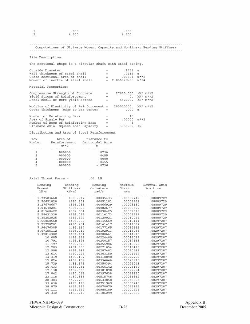
FHWA NHI-05-039 Appendix B Micropile Design & Construction B-28 December 2005
1 .000 .000 2 4.500 4.500 ------------------------------------------------------------------------------ Computations of Ultimate Moment Capacity and Nonlinear Bending Stiffness ------------------------------------------------------------------------------ Pile Description: The sectional shape is a circular shaft with steel casing. Outside Diameter = .1778 m Wall thickness of steel shell = .0115 m Cross-sectional area of shell = .00601 m**2 Moment of inertia of steel shell = 2.08692E-05 m**4 Material Properties: Compressive Strength of Concrete = 27600.000 kN/ m**2 Yield Stress of Reinforcement = 0. kN/ m**2 Steel shell or core yield stress = 552000. kN/ m**2 Modulus of Elasticity of Reinforcement = 200000000. kN/ m**2 Cover Thickness (edge to bar center) = .000 m Number of Reinforcing Bars = 10 Area of Single Bar = .00000 m**2 Number of Rows of Reinforcing Bars = 5 Ultimate Axial Squash Load Capacity = 3758.02 kN Distribution and Area of Steel Reinforcement Row Area of Distance to Number Reinforcement Centroidal Axis m**2 m ------ ------------- --------------- 1 .000000 .0736 2 .000000 .0455 3 .000000 .0000 4 .000000 -.0455 5 .000000 -.0736 Axial Thrust Force = .00 kN Bending Bending Bending Maximum Neutral Axis Moment Stiffness Curvature Strain Position kN-m kN-m2 rad/m m/m m ------------- ------------- ------------- ------------- ------------- 1.73583660 4898.917 .00035433 .00002742 .08889729 2.50651820 4897.351 .00051181 .00003961 .08889729 3.27670667 4895.785 .00066929 .00005180 .08889729 4.04640201 4894.220 .00082677 .00006399 .08889729 4.81560422 4892.654 .00098425 .00007618 .08889729 5.58431330 4891.088 .00114173 .00008837 .08889729 6.35252925 4889.522 .00129921 .00010056 .08889729 6.55060560 4496.902 .00145669 .00010411 .08297207 7.25778201 4496.284 .00161417 .00011537 .08297207 7.96476385 4495.667 .00177165 .00012662 .08297207 8.67155112 4495.049 .00192913 .00013788 .08297207 9.37814382 4494.431 .00208661 .00014913 .08297207 10.085 4493.813 .00224409 .00016039 .08297207 10.791 4493.196 .00240157 .00017165 .08297207 11.497 4492.578 .00255906 .00018290 .08297207 12.203 4491.960 .00271654 .00019416 .08297207 12.908 4491.342 .00287402 .00020541 .08297207 13.614 4490.725 .00303150 .00021667 .08297207 14.319 4490.107 .00318898 .00022792 .08297207 15.024 4489.489 .00334646 .00023918 .08297207 15.729 4488.871 .00350394 .00025043 .08297207 16.433 4488.254 .00366142 .00026169 .08297207 17.138 4487.636 .00381890 .00027294 .08297207 17.842 4487.018 .00397638 .00028420 .08297207 23.118 4482.385 .00515748 .00036862 .08297207 28.383 4477.752 .00633858 .00045303 .08297207 33.636 4473.118 .00751969 .00053745 .08297207 38.879 4468.485 .00870079 .00062186 .08297207 44.111 4463.852 .00988189 .00070628 .08297207 49.332 4459.219 .01106299 .00079069 .08297207
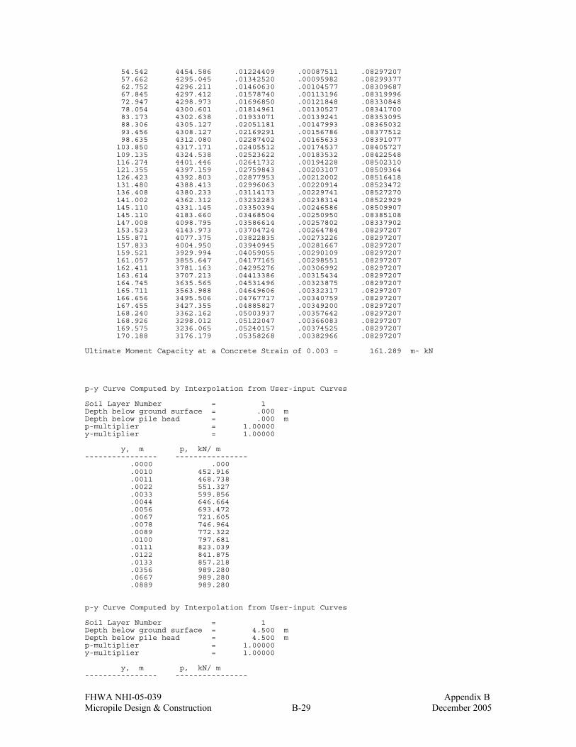
FHWA NHI-05-039 Appendix B Micropile Design & Construction B-29 December 2005
54.542 4454.586 .01224409 .00087511 .08297207 57.662 4295.045 .01342520 .00095982 .08299377 62.752 4296.211 .01460630 .00104577 .08309687 67.845 4297.412 .01578740 .00113196 .08319996 72.947 4298.973 .01696850 .00121848 .08330848 78.054 4300.601 .01814961 .00130527 .08341700 83.173 4302.638 .01933071 .00139241 .08353095 88.306 4305.127 .02051181 .00147993 .08365032 93.456 4308.127 .02169291 .00156786 .08377512 98.635 4312.080 .02287402 .00165633 .08391077 103.850 4317.171 .02405512 .00174537 .08405727 109.135 4324.538 .02523622 .00183532 .08422548 116.274 4401.446 .02641732 .00194228 .08502310 121.355 4397.159 .02759843 .00203107 .08509364 126.423 4392.803 .02877953 .00212002 .08516418 131.480 4388.413 .02996063 .00220914 .08523472 136.408 4380.233 .03114173 .00229741 .08527270 141.002 4362.312 .03232283 .00238314 .08522929 145.110 4331.145 .03350394 .00246586 .08509907 145.110 4183.660 .03468504 .00250950 .08385108 147.008 4098.795 .03586614 .00257802 .08337902 153.523 4143.973 .03704724 .00264784 .08297207 155.871 4077.375 .03822835 .00273226 .08297207 157.833 4004.950 .03940945 .00281667 .08297207 159.521 3929.994 .04059055 .00290109 .08297207 161.057 3855.647 .04177165 .00298551 .08297207 162.411 3781.163 .04295276 .00306992 .08297207 163.614 3707.213 .04413386 .00315434 .08297207 164.745 3635.565 .04531496 .00323875 .08297207 165.711 3563.988 .04649606 .00332317 .08297207 166.656 3495.506 .04767717 .00340759 .08297207 167.455 3427.355 .04885827 .00349200 .08297207 168.240 3362.162 .05003937 .00357642 .08297207 168.926 3298.012 .05122047 .00366083 .08297207 169.575 3236.065 .05240157 .00374525 .08297207 170.188 3176.179 .05358268 .00382966 .08297207 Ultimate Moment Capacity at a Concrete Strain of 0.003 = 161.289 m- kN p-y Curve Computed by Interpolation from User-input Curves Soil Layer Number = 1 Depth below ground surface = .000 m Depth below pile head = .000 m p-multiplier = 1.00000 y-multiplier = 1.00000 y, m p, kN/ m ---------------- ---------------- .0000 .000 .0010 452.916 .0011 468.738 .0022 551.327 .0033 599.856 .0044 646.664 .0056 693.472 .0067 721.605 .0078 746.964 .0089 772.322 .0100 797.681 .0111 823.039 .0122 841.875 .0133 857.218 .0356 989.280 .0667 989.280 .0889 989.280 p-y Curve Computed by Interpolation from User-input Curves Soil Layer Number = 1 Depth below ground surface = 4.500 m Depth below pile head = 4.500 m p-multiplier = 1.00000 y-multiplier = 1.00000 y, m p, kN/ m ---------------- ----------------

FHWA NHI-05-039 Appendix B Micropile Design & Construction B-30 December 2005
.0000 .000 .0010 452.916 .0011 468.738 .0022 551.327 .0033 599.856 .0044 646.664 .0056 693.472 .0067 721.605 .0078 746.964 .0089 772.322 .0100 797.681 .0111 823.039 .0122 841.875 .0133 857.218 .0356 989.280 .0667 989.280 .0889 989.280 ------------------------------------------------------------------------------ Computed Values of Load Distribution and Deflection for Lateral Loading for Load Case Number 1 ------------------------------------------------------------------------------ Pile-head boundary conditions are Shear and Moment (BC Type 1) Specified shear force at pile head = 365.000 kN Specified bending moment at pile head = 83.550 m- kN Specified axial load at pile head = .000 kN Non-zero moment for this load case indicates the pile-head may rotate under the applied pile-head loading, but is not a free-head (zero moment )condition. Depth Deflect. Moment Shear Slope Total Flx. Rig. Soil Res X y M V S Stress EI p m m kN- m kN Rad. kN/ m**2 kN- m**2 kN/ m -------- --------- --------- --------- --------- --------- --------- --------- 0.000 .018217 83.5500 365.0 -.034791 7.4276 4308.873 -924.626 .03103 .017146 94.4323 336.5 -.034150 8.3950 4308.873 -909.848 .06207 .016097 104.4 308.5 -.033434 9.2846 4308.873 -895.361 .09310 .015071 113.6 281.0 -.032654 10.0974 4372.671 -881.196 .124 .014070 121.9 253.8 -.031821 10.8349 4396.710 -867.377 .155 .013096 129.3 227.1 -.030934 11.4980 4390.275 -853.926 .186 .012150 136.0 200.8 -.029995 12.0880 4380.956 -840.867 .217 .011234 141.8 175.0 -.029009 12.6061 4356.298 -825.824 .248 .010350 146.8 149.6 -.027949 13.0534 4107.092 -805.638 .279 .009499 151.1 124.9 -.026826 13.4318 4127.178 -786.238 .310 .008685 154.6 100.8 -.025675 13.7428 4114.353 -767.642 .341 .007906 157.3 77.2742 -.024485 13.9881 4023.546 -749.872 .372 .007165 159.4 54.2647 -.023250 14.1692 3936.500 -732.961 .403 .006463 160.7 31.7662 -.021978 14.2875 3873.168 -716.940 .434 .005801 161.4 9.7508 -.020682 14.3445 3840.358 -701.832 .466 .005179 161.3 -11.6541 -.019378 14.3413 3842.253 -677.591 .497 .004598 160.6 -32.3029 -.018084 14.2802 3877.346 -653.111 .528 .004057 159.3 -52.2180 -.016814 14.1631 3939.755 -630.311 .559 .003554 157.4 -71.4511 -.015579 13.9920 4021.915 -609.152 .590 .003090 154.9 -90.0521 -.014386 13.7688 4106.068 -589.582 .621 .002661 151.8 -108.1 -.013231 13.4951 4132.105 -571.541 .652 .002268 148.2 -125.5 -.012101 13.1725 4106.921 -554.288 .683 .001910 144.0 -142.4 -.011026 12.8024 4339.559 -531.243 .714 .001584 139.3 -158.5 -.010017 12.3868 4368.838 -508.070 .745 .001289 134.2 -173.9 -.009047 11.9278 4383.952 -483.492 .776 .001023 128.5 -188.5 -.008118 11.4273 4390.966 -456.274 .807 7.85E-04 122.5 -202.1 -.007231 10.8877 4396.200 -420.874 .838 5.74E-04 116.0 -214.6 -.006390 10.3122 4398.493 -388.085 .869 3.88E-04 109.1 -226.1 -.005589 9.7033 4324.687 -350.722 .900 2.27E-04 102.0 -236.5 -.004830 9.0645 4315.330 -318.257 .931 8.83E-05 94.4704 -245.0 -.004124 8.3984 4308.902 -232.174 .962 -2.92E-05 86.7542 -247.4 -.003471 7.7124 4304.375 76.704 .993 -1.27E-04 79.1119 -242.0 -.002872 7.0330 4301.022 276.556 1.024 -2.07E-04 71.7359 -232.8 -.002328 6.3773 4298.603 314.318 1.055 -2.72E-04 64.6627 -222.8 -.001836 5.7485 4296.661 327.253 1.086 -3.21E-04 57.9047 -212.5 -.001393 5.1477 4295.101 337.267 1.117 -3.58E-04 51.4715 -201.9 -.001005 4.5758 4457.318 344.665 1.148 -3.84E-04 45.3703 -191.2 -6.68E-04 4.0334 4462.736 349.823 1.179 -4.00E-04 39.6060 -180.3 -3.72E-04 3.5210 4467.843 353.010 1.210 -4.07E-04 34.1817 -169.3 -1.16E-04 3.0388 4472.637 354.477 1.241 -4.07E-04 29.0988 -158.3 1.03E-04 2.5869 4477.121 354.462 1.272 -4.00E-04 24.3573 -147.3 2.89E-04 2.1654 4481.295 353.187

FHWA NHI-05-039 Appendix B Micropile Design & Construction B-31 December 2005
1.303 -3.89E-04 19.9560 -136.4 4.42E-04 1.7741 4485.163 350.857 1.334 -3.73E-04 15.8926 -125.5 5.66E-04 1.4129 4488.728 347.665 1.366 -3.54E-04 12.1641 -114.8 6.63E-04 1.0814 4491.994 343.786 1.397 -3.32E-04 8.7666 -104.2 7.35E-04 .7794 4494.966 339.382 1.428 -3.08E-04 5.6961 -93.7483 7.83E-04 .5064 4890.861 334.599 1.459 -2.83E-04 2.9478 -83.4419 8.11E-04 .2621 4896.454 329.591 1.490 -2.58E-04 .5169 -73.2928 8.22E-04 4.60E-02 4898.917 324.466 1.521 -2.32E-04 -1.6014 -63.3030 8.18E-04 .1424 4898.917 319.321 1.552 -2.07E-04 -3.4122 -53.4719 8.03E-04 .3033 4895.509 314.239 1.583 -1.82E-04 -4.9204 -43.8773 7.76E-04 .4374 4892.440 304.075 1.614 -1.59E-04 -6.1357 -34.6228 7.41E-04 .5455 4889.964 292.328 1.645 -1.36E-04 -7.0694 -25.7235 6.97E-04 .6285 4496.449 281.182 1.676 -1.16E-04 -7.7323 -17.1585 6.46E-04 .6874 4495.870 270.789 1.707 -9.63E-05 -8.1344 -9.0255 5.91E-04 .7231 4495.518 253.333 1.738 -7.88E-05 -8.2925 -1.8770 5.35E-04 .7372 4495.380 207.349 1.769 -6.31E-05 -8.2509 3.9169 4.78E-04 .7335 4495.416 166.039 1.800 -4.92E-05 -8.0494 8.5010 4.21E-04 .7156 4495.593 129.379 1.831 -3.70E-05 -7.7232 12.0177 3.67E-04 .6866 4495.878 97.255 1.862 -2.64E-05 -7.3034 14.6051 3.15E-04 .6493 4496.244 69.484 1.893 -1.74E-05 -6.8167 16.3944 2.66E-04 .6060 4496.670 45.829 1.924 -9.89E-06 -6.2859 17.5092 2.23E-04 .5588 4889.658 26.015 1.955 -3.60E-06 -5.7299 18.0596 1.85E-04 .5094 4890.791 9.457 1.986 1.57E-06 -5.1649 18.1423 1.50E-04 .4592 4891.942 -4.131 2.017 5.72E-06 -4.6039 17.8447 1.19E-04 .4093 4893.085 -15.045 2.048 8.96E-06 -4.0573 17.2454 9.16E-05 .3607 4894.197 -23.575 2.079 1.14E-05 -3.5335 16.4140 6.76E-05 .3141 4895.263 -30.005 2.110 1.32E-05 -3.0385 15.4115 4.67E-05 .2701 4896.269 -34.605 2.141 1.43E-05 -2.5769 14.2905 2.89E-05 .2291 4897.208 -37.633 2.172 1.50E-05 -2.1515 13.0963 1.39E-05 .1913 4898.072 -39.329 2.203 1.52E-05 -1.7640 11.8667 1.54E-06 .1568 4898.859 -39.911 2.234 1.50E-05 -1.4150 10.6332 -8.53E-06 .1258 4898.917 -39.580 2.266 1.46E-05 -1.1040 9.4213 -1.65E-05 9.81E-02 4898.917 -38.518 2.297 1.40E-05 -.8302 8.2513 -2.26E-05 7.38E-02 4898.917 -36.885 2.328 1.32E-05 -.5919 7.1386 -2.71E-05 5.26E-02 4898.917 -34.823 2.359 1.23E-05 -.3871 6.0946 -3.02E-05 3.44E-02 4898.917 -32.455 2.390 1.14E-05 -.2136 5.1272 -3.21E-05 1.90E-02 4898.917 -29.886 2.421 1.03E-05 -6.89E-02 4.2413 -3.30E-05 6.12E-03 4898.917 -27.207 2.452 9.31E-06 4.97E-02 3.4391 -3.31E-05 4.41E-03 4898.917 -24.492 2.483 8.29E-06 .1446 2.7207 -3.25E-05 1.29E-02 4898.917 -21.803 2.514 7.29E-06 .2185 2.0847 -3.13E-05 1.94E-02 4898.917 -19.188 2.545 6.34E-06 .2740 1.5280 -2.98E-05 2.44E-02 4898.917 -16.687 2.576 5.45E-06 .3134 1.0467 -2.79E-05 2.79E-02 4898.917 -14.327 2.607 4.61E-06 .3390 .6362 -2.58E-05 3.01E-02 4898.917 -12.130 2.638 3.84E-06 .3529 .2911 -2.37E-05 3.14E-02 4898.917 -10.108 2.669 3.14E-06 .3570 5.98E-03 -2.14E-05 3.17E-02 4898.917 -8.268 2.700 2.51E-06 .3532 -.2249 -1.92E-05 3.14E-02 4898.917 -6.613 2.731 1.95E-06 .3431 -.4073 -1.69E-05 3.05E-02 4898.917 -5.140 2.762 1.46E-06 .3280 -.5467 -1.48E-05 2.92E-02 4898.917 -3.845 2.793 1.03E-06 .3091 -.6486 -1.28E-05 2.75E-02 4898.917 -2.720 2.824 6.67E-07 .2877 -.7181 -1.09E-05 2.56E-02 4898.917 -1.755 2.855 3.57E-07 .2646 -.7598 -9.17E-06 2.35E-02 4898.917 -.937989 2.886 9.81E-08 .2405 -.7784 -7.57E-06 2.14E-02 4898.917 -.258135 2.917 -1.13E-07 .2162 -.7778 -6.12E-06 1.92E-02 4898.917 .297320 2.948 -2.82E-07 .1923 -.7617 -4.82E-06 1.71E-02 4898.917 .740935 2.979 -4.12E-07 .1690 -.7333 -3.68E-06 1.50E-02 4898.917 1.085 3.010 -5.10E-07 .1467 -.6957 -2.68E-06 1.30E-02 4898.917 1.342 3.041 -5.79E-07 .1258 -.6512 -1.82E-06 1.12E-02 4898.917 1.523 3.072 -6.23E-07 .1063 -.6022 -1.08E-06 9.45E-03 4898.917 1.639 3.103 -6.46E-07 8.84E-02 -.5504 -4.65E-07 7.86E-03 4898.917 1.700 3.134 -6.52E-07 7.21E-02 -.4974 4.31E-08 6.41E-03 4898.917 1.715 3.166 -6.43E-07 5.75E-02 -.4445 4.54E-07 5.12E-03 4898.917 1.692 3.197 -6.24E-07 4.46E-02 -.3928 7.77E-07 3.96E-03 4898.917 1.641 3.228 -5.95E-07 3.32E-02 -.3431 1.02E-06 2.95E-03 4898.917 1.566 3.259 -5.60E-07 2.33E-02 -.2959 1.20E-06 2.07E-03 4898.917 1.473 3.290 -5.21E-07 1.48E-02 -.2518 1.32E-06 1.31E-03 4898.917 1.369 3.321 -4.78E-07 7.64E-03 -.2110 1.39E-06 6.79E-04 4898.917 1.257 3.352 -4.34E-07 1.69E-03 -.1738 1.42E-06 1.51E-04 4898.917 1.142 3.383 -3.90E-07 -3.15E-03 -.1402 1.42E-06 2.80E-04 4898.917 1.025 3.414 -3.46E-07 -7.01E-03 -.1101 1.39E-06 6.23E-04 4898.917 .910081 3.445 -3.04E-07 -9.99E-03 -8.36E-02 1.33E-06 8.88E-04 4898.917 .798699 3.476 -2.63E-07 -1.22E-02 -6.05E-02 1.26E-06 1.08E-03 4898.917 .692482 3.507 -2.25E-07 -1.37E-02 -4.06E-02 1.18E-06 1.22E-03 4898.917 .592574 3.538 -1.90E-07 -1.47E-02 -2.36E-02 1.09E-06 1.31E-03 4898.917 .499773 3.569 -1.58E-07 -1.52E-02 -9.42E-03 9.95E-07 1.35E-03 4898.917 .414584 3.600 -1.28E-07 -1.53E-02 2.25E-03 8.99E-07 1.36E-03 4898.917 .337260 3.631 -1.02E-07 -1.51E-02 1.16E-02 8.02E-07 1.34E-03 4898.917 .267849 3.662 -7.84E-08 -1.46E-02 1.90E-02 7.09E-07 1.30E-03 4898.917 .206231 3.693 -5.78E-08 -1.39E-02 2.46E-02 6.18E-07 1.23E-03 4898.917 .152152 3.724 -4.00E-08 -1.31E-02 2.86E-02 5.33E-07 1.16E-03 4898.917 .105257 3.755 -2.48E-08 -1.21E-02 3.12E-02 4.53E-07 1.08E-03 4898.917 .065112 3.786 -1.19E-08 -1.11E-02 3.27E-02 3.80E-07 9.88E-04 4898.917 .031234

FHWA NHI-05-039 Appendix B Micropile Design & Construction B-32 December 2005
3.817 -1.18E-09 -1.01E-02 3.32E-02 3.13E-07 8.97E-04 4898.917 .003106 3.848 7.53E-09 -9.05E-03 3.30E-02 2.52E-07 8.05E-04 4898.917 -.019805 3.879 1.45E-08 -8.04E-03 3.21E-02 1.98E-07 7.15E-04 4898.917 -.038032 3.910 1.98E-08 -7.06E-03 3.07E-02 1.50E-07 6.28E-04 4898.917 -.052101 3.941 2.38E-08 -6.14E-03 2.89E-02 1.08E-07 5.46E-04 4898.917 -.062516 3.972 2.65E-08 -5.27E-03 2.68E-02 7.20E-08 4.69E-04 4898.917 -.069757 4.003 2.82E-08 -4.47E-03 2.46E-02 4.11E-08 3.98E-04 4898.917 -.074271 4.034 2.91E-08 -3.74E-03 2.23E-02 1.51E-08 3.33E-04 4898.917 -.076472 4.066 2.92E-08 -3.09E-03 1.99E-02 -6.55E-09 2.75E-04 4898.917 -.076737 4.097 2.87E-08 -2.51E-03 1.75E-02 -2.43E-08 2.23E-04 4898.917 -.075404 4.128 2.77E-08 -2.00E-03 1.52E-02 -3.86E-08 1.78E-04 4898.917 -.072772 4.159 2.63E-08 -1.57E-03 1.30E-02 -4.99E-08 1.39E-04 4898.917 -.069104 4.190 2.46E-08 -1.19E-03 1.09E-02 -5.86E-08 1.06E-04 4898.917 -.064628 4.221 2.26E-08 -8.85E-04 9.02E-03 -6.52E-08 7.87E-05 4898.917 -.059533 4.252 2.05E-08 -6.34E-04 7.26E-03 -7.00E-08 5.64E-05 4898.917 -.053981 4.283 1.83E-08 -4.35E-04 5.68E-03 -7.34E-08 3.86E-05 4898.917 -.048101 4.314 1.60E-08 -2.82E-04 4.28E-03 -7.57E-08 2.50E-05 4898.917 -.041996 4.345 1.36E-08 -1.69E-04 3.07E-03 -7.71E-08 1.50E-05 4898.917 -.035745 4.376 1.12E-08 -9.10E-05 2.06E-03 -7.79E-08 8.09E-06 4898.917 -.029407 4.407 8.75E-09 -4.11E-05 1.25E-03 -7.83E-08 3.66E-06 4898.917 -.023022 4.438 6.32E-09 -1.35E-05 6.33E-04 -7.85E-08 1.20E-06 4898.917 -.016615 4.469 3.88E-09 -1.82E-06 2.17E-04 -7.86E-08 1.62E-07 4898.917 -.010202 4.500 1.44E-09 0.0 0.0 -7.86E-08 0.0 4898.917 -.003788 Please note that because this analysis makes computations of ultimate moment capacity and pile response using nonlinear bending stiffness that the above values of total stress due to combined axial stress and bending may not be representative of actual conditions. Output Verification: Computed forces and moments are within specified convergence limits. Output Summary for Load Case No. 1: Pile-head deflection = .01821670 m Computed slope at pile head = -.03479080 Maximum bending moment = 161.355 kN- m Maximum shear force = 365.000 kN Depth of maximum bending moment = .43448276 m Depth of maximum shear force = 0.000 m Number of iterations = 24 Number of zero deflection points = 5 ------------------------------------------------------------------------------ Summary of Pile-head Response ------------------------------------------------------------------------------ Definition of symbols for pile-head boundary conditions: y = pile-head displacment, m M = pile-head moment, kN- m V = pile-head shear force, kN S = pile-head slope, radians R = rotational stiffness of pile-head, m- kN/rad BC Boundary Boundary Axial Pile Head Maximum Maximum Type Condition Condition Load Deflection Moment Shear 1 2 kN m m- kN kN ---- ------------ ------------ ----------- ----------- ----------- ----------- 1 V = 365.000 M = 83.550 0.0000 .018217 161.3551 365.0000

FHWA NHI-05-039 Appendix B Micropile Design & Construction B-33 December 2005
============================================================================== LPILE Plus for Windows, Version 4.0 (4.0.8) Analysis of Individual Piles and Drilled Shafts Subjected to Lateral Loading Using the p-y Method (c) Copyright ENSOFT, Inc., 1985-2003 All Rights Reserved ============================================================================== Path to file locations: L:\Programs\LPILE\Chapter 6\Ch. 6 Example with P=474.5\P=Pult\ Name of input data file: Up analysis.lpd Name of output file: Up analysis.lpo Name of plot output file: Up analysis.lpp Name of runtime file: Up analysis.lpr ------------------------------------------------------------------------------ Time and Date of Analysis ------------------------------------------------------------------------------ Date: May 4, 2005 Time: 17: 5:12 ------------------------------------------------------------------------------
Problem Title ------------------------------------------------------------------------------
Up Analysis for P=474.5 Case ------------------------------------------------------------------------------ Program Options ------------------------------------------------------------------------------ Units Used in Computations - SI Units, meters, kilopascals Basic Program Options: Analysis Type 3: - Computation of Nonlinear Bending Stiffness and Ultimate Bending Moment Capacity with Pile Response Computed Using Nonlinear EI Computation Options: - User-specified p-y curves used in analysis - Analysis uses p-y multiplers for group action - Analysis assumes no shear resistance at pile tip - Analysis for fixed-length pile or shaft only - No computation of foundation stiffness matrix elements - Output pile response for full length of pile - Analysis assumes no soil movements acting on pile - Additional p-y curves computed at specified depths Solution Control Parameters: - Number of pile increments = 145 - Maximum number of iterations allowed = 100 - Deflection tolerance for convergence = 2.5400E-07 m - Maximum allowable deflection = 2.5400E+00 m Printing Options: - Values of pile-head deflection, bending moment, shear force, and soil reaction are printed for full length of pile. - Printing Increment (spacing of output points) = 1 ------------------------------------------------------------------------------ Pile Structural Properties and Geometry ------------------------------------------------------------------------------ Pile Length = 10.00 m Depth of ground surface below top of pile = .00 m Slope angle of ground surface = .00 deg. Structural properties of pile defined using 2 points Point Depth Pile Moment of Pile Modulus of X Diameter Inertia Area Elasticity m m m**4 Sq. m kN/Sq. m

FHWA NHI-05-039 Appendix B Micropile Design & Construction B-34 December 2005
----- --------- ----------- ---------- ---------- ----------- 1 0.0000 .17780000 1.0000 .024800 200000000.000 2 10.0000 .17780000 1.0000 .024800 200000000.000 Please note that because this analysis makes computations of ultimate moment capacity and pile response using nonlinear bending stiffness that the above values of moment of inertia and modulus of are not used for any computations other than total stress due to combined axial loading and bending. ------------------------------------------------------------------------------ Soil and Rock Layering Information ------------------------------------------------------------------------------ The soil profile is modelled using 4 layers Layer 1 is modelled using user-specied p-y curves Distance from top of pile to top of layer = .000 m Distance from top of pile to bottom of layer = 5.290 m Layer 2 is modelled using user-specied p-y curves Distance from top of pile to top of layer = 5.290 m Distance from top of pile to bottom of layer = 5.310 m Layer 3 is modelled using user-specied p-y curves Distance from top of pile to top of layer = 5.310 m Distance from top of pile to bottom of layer = 8.000 m Layer 4 is modelled using user-specied p-y curves Distance from top of pile to top of layer = 8.000 m Distance from top of pile to bottom of layer = 10.000 m (Depth of lowest layer extends .00 m below pile tip) ------------------------------------------------------------------------------ Effective Unit Weight of Soil vs. Depth ------------------------------------------------------------------------------ Distribution of effective unit weight of soil with depth is defined using 8 points Point Depth X Eff. Unit Weight No. m kN/ m**3 ----- ---------- ---------------- 1 .00 11.40000 2 5.29 11.40000 3 5.29 11.40000 4 5.31 21.20000 5 5.31 21.20000 6 8.00 21.20000 7 8.00 21.20000 8 10.00 21.20000 ------------------------------------------------------------------------------ Shear Strength of Soils ------------------------------------------------------------------------------ Distribution of shear strength parameters with depth defined using 0 points Point Depth X Cohesion c Angle of Friction E50 or RQD No. m kN/ m**2 Deg. k_rm % ----- -------- ---------- ------------------ ------ ------ Notes: (1) Cohesion = uniaxial compressive strength for rock materials. (2) Values of E50 are reported for clay strata. (3) Default values will be generated for E50 when input values are 0. (4) RQD and k_rm are reported only for weak rock strata. ------------------------------------------------------------------------------ p-y Modification Factors ------------------------------------------------------------------------------ Distribution of p-y multipliers with depth defined using 5 points

FHWA NHI-05-039 Appendix B Micropile Design & Construction B-35 December 2005
Point Depth X p-mult y-mult No. m ----- ---------- ---------- ---------- 1 .000 1.0000 1.0000 2 5.290 1.0000 1.0000 3 5.310 1.0000 1.0000 4 8.000 1.0000 1.0000 5 10.000 1.0000 1.0000 ------------------------------------------------------------------------------ User-specified p-y Curves ------------------------------------------------------------------------------ User-specified p-y curves defined using 8 curves. User-specified curve number 1 at depth = .000 m Point y p, No. m kN/ m ----- ---------- ---------- 1 .0000 .000 2 .0002 92.072 3 .0004 109.493 4 .0009 137.680 5 .0018 163.731 6 .0027 181.198 7 .0037 194.710 8 .0092 244.834 9 .0183 291.159 10 .0366 346.248 11 .0412 346.248 12 .0458 346.248 User-specified curve number 2 at depth = 5.290 m Point y p, No. m kN/ m ----- ---------- ---------- 1 .0000 .000 2 .0002 92.072 3 .0004 109.493 4 .0009 137.680 5 .0018 163.731 6 .0027 181.198 7 .0037 194.710 8 .0092 244.834 9 .0183 291.159 10 .0366 346.248 11 .0412 346.248 12 .0458 346.248 User-specified curve number 3 at depth = 5.290 m Point y p, No. m kN/ m ----- ---------- ---------- 1 .0000 .000 2 .0002 92.072 3 .0004 109.493 4 .0009 137.680 5 .0018 163.731 6 .0027 181.198 7 .0037 194.710 8 .0092 244.834 9 .0183 291.159 10 .0366 346.248 11 .0412 346.248 12 .0458 346.298 User-specified curve number 4 at depth = 5.310 m Point y p, No. m kN/ m ----- ---------- ----------

FHWA NHI-05-039 Appendix B Micropile Design & Construction B-36 December 2005
1 .0000 .000 2 .0002 65.766 3 .0005 78.209 4 .0011 98.343 5 .0023 116.950 6 .0034 129.427 7 .0046 139.078 8 .0115 174.882 9 .0229 207.971 10 .0458 247.320 11 .0515 247.320 12 .0573 247.320 User-specified curve number 5 at depth = 5.310 m Point y p, No. m kN/ m ----- ---------- ---------- 1 .0000 .000 2 .0002 65.766 3 .0005 78.209 4 .0011 98.343 5 .0023 116.950 6 .0034 129.427 7 .0046 139.078 8 .0115 174.882 9 .0229 207.971 10 .0458 247.320 11 .0515 247.320 12 .0573 247.320 User-specified curve number 6 at depth = 8.000 m Point y p, No. m kN/ m ----- ---------- ---------- 1 .0000 .000 2 .0002 56.414 3 .0005 67.088 4 .0011 84.358 5 .0023 100.319 6 .0034 111.022 7 .0046 119.300 8 .0115 150.012 9 .0229 178.396 10 .0458 212.150 11 .0515 212.150 12 .0573 212.150 User-specified curve number 7 at depth = 8.000 m Point y p, No. m kN/ m ----- ---------- ---------- 1 .0000 .000 2 .0002 56.414 3 .0005 67.088 4 .0011 84.358 5 .0023 100.319 6 .0034 111.022 7 .0046 119.300 8 .0115 150.012 9 .0229 178.396 10 .0458 212.150 11 .0515 212.150 12 .0573 212.150 User-specified curve number 8 at depth = 10.000 m Point y p, No. m kN/ m ----- ---------- ---------- 1 .0000 .000 2 .0005 26.070 3 .0011 32.781 4 .0020 21.922 5 .0023 38.983 6 .0034 43.142 7 .0046 46.359 8 .0115 58.294 9 .0151 82.440

FHWA NHI-05-039 Appendix B Micropile Design & Construction B-37 December 2005
10 .0229 69.324 11 .0458 82.440 12 .0573 82.440 ------------------------------------------------------------------------------ Loading Type ------------------------------------------------------------------------------ Static loading criteria was used for computation of p-y curves ------------------------------------------------------------------------------ Pile-head Loading and Pile-head Fixity Conditions ------------------------------------------------------------------------------ Number of loads specified = 1 Load Case Number 1 Pile-head boundary conditions are Shear and Moment (BC Type 1) Shear force at pile head = 330.000 kN Bending moment at pile head = -76.200 m- kN Axial load at pile head = 474.500 kN Non-zero moment at pile head for this load case indicates the pile-head may rotate under the applied pile-head loading, but is not a free-head (zero moment) condition. ------------------------------------------------------------------------------ Output of p-y Curves at Specified Depths ------------------------------------------------------------------------------ p-y curves are generated and printed for verification at 5 depths. Depth Depth Below Pile Head Depth Below Ground Surface No. m m ----- --------------------- -------------------------- 1 .000 .000 2 5.290 5.290 3 5.310 5.310 4 8.000 8.000 5 10.000 10.000 Depth of ground surface below top of pile = .00 m ------------------------------------------------------------------------------ Computations of Ultimate Moment Capacity and Nonlinear Bending Stiffness ------------------------------------------------------------------------------ Pile Description: The sectional shape is a circular shaft with steel casing. Outside Diameter = .1778 m Wall thickness of steel shell = .0115 m Cross-sectional area of shell = .00601 m**2 Moment of inertia of steel shell = 2.08692E-05 m**4 Material Properties: Compressive Strength of Concrete = 27600.000 kN/ m**2 Yield Stress of Reinforcement = 0. kN/ m**2 Steel shell or core yield stress = 552000. kN/ m**2 Modulus of Elasticity of Reinforcement = 200000000. kN/ m**2 Cover Thickness (edge to bar center) = .000 m Number of Reinforcing Bars = 10 Area of Single Bar = .00000 m**2 Number of Rows of Reinforcing Bars = 5

FHWA NHI-05-039 Appendix B Micropile Design & Construction B-38 December 2005
Ultimate Axial Squash Load Capacity = 3758.02 kN Distribution and Area of Steel Reinforcement Row Area of Distance to Number Reinforcement Centroidal Axis m**2 m ------ ------------- --------------- 1 .000000 .0736 2 .000000 .0455 3 .000000 .0000 4 .000000 -.0455 5 .000000 -.0736 Axial Thrust Force = 474.50 kN Bending Bending Bending Maximum Neutral Axis Moment Stiffness Curvature Strain Position kN-m kN-m2 rad/m m/m m ------------- ------------- ------------- ------------- ------------- 1.69826245 4792.874 .00035433 .00031727 .90691267 2.45303965 4792.862 .00051181 .00032949 .65527803 3.20781175 4792.848 .00066929 .00034172 .52206775 3.96257836 4792.833 .00082677 .00035395 .43960844 4.71733626 4792.814 .00098425 .00036619 .38354674 5.47208598 4792.792 .00114173 .00037843 .34295465 6.22682760 4792.770 .00129921 .00039068 .31220536 6.98155916 4792.746 .00145669 .00040293 .28810838 7.73628058 4792.720 .00161417 .00041519 .26871577 8.49098340 4792.688 .00177165 .00042746 .25277953 9.24568013 4792.659 .00192913 .00043973 .23944236 10.000 4792.625 .00208661 .00045201 .22812367 10.755 4792.590 .00224409 .00046429 .21839481 11.510 4792.551 .00240157 .00047658 .20994649 12.264 4792.509 .00255906 .00048888 .20253996 13.019 4792.470 .00271654 .00050118 .19599075 13.774 4792.426 .00287402 .00051348 .19016320 14.528 4792.379 .00303150 .00052579 .18494336 15.283 4792.326 .00318898 .00053812 .18024442 16.035 4791.716 .00334646 .00055042 .17597957 16.774 4787.090 .00350394 .00056260 .17206198 17.571 4799.091 .00366142 .00057505 .16855677 18.301 4792.220 .00381890 .00058745 .16532828 19.053 4791.556 .00397638 .00059979 .16233854 24.610 4771.704 .00515748 .00068957 .14520315 29.767 4696.101 .00633858 .00078032 .13460612 35.334 4698.840 .00751969 .00087092 .12731897 39.786 4572.710 .00870079 .00095706 .12149685 45.804 4635.195 .00988189 .00105014 .11776917 50.555 4569.762 .01106299 .00113526 .11411745 56.180 4588.341 .01224409 .00122769 .11176798 61.386 4572.465 .01342520 .00131523 .10946735 64.845 4439.494 .01460630 .00139171 .10678147 71.647 4538.208 .01578740 .00149414 .10614120 74.736 4404.370 .01696850 .00156633 .10380800 81.890 4511.946 .01814961 .00167053 .10354213 85.716 4434.167 .01933071 .00175060 .10206082 92.018 4486.089 .02051181 .00183074 .10075315 97.124 4477.213 .02169291 .00193616 .10075315 102.139 4465.294 .02287402 .00202929 .10021598 105.295 4377.229 .02405512 .00210249 .09890288 109.026 4320.217 .02523622 .00218134 .09793705 113.742 4305.584 .02641732 .00227957 .09779054 118.611 4297.758 .02759843 .00238148 .09779054 127.233 4420.944 .02877953 .00247762 .09758978 131.954 4404.252 .02996063 .00257166 .09733476 136.319 4377.388 .03114173 .00266730 .09715027 140.277 4339.870 .03232283 .00276706 .09710686 143.850 4293.538 .03350394 .00287126 .09719911 147.136 4242.066 .03468504 .00297869 .09737816 150.123 4185.651 .03586614 .00308557 .09753009 152.748 4123.053 .03704724 .00319502 .09774171 152.748 3995.667 .03822835 .00329874 .09779054 152.748 3875.917 .03940945 .00340066 .09779054 154.387 3803.521 .04059055 .00350258 .09779054 155.966 3733.787 .04177165 .00360450 .09779054 157.340 3663.103 .04295276 .00370642 .09779054 158.551 3592.498 .04413386 .00380833 .09779054

FHWA NHI-05-039 Appendix B Micropile Design & Construction B-39 December 2005
Ultimate Moment Capacity at a Concrete Strain of 0.003 = 147.732 m- kN p-y Curve Computed by Interpolation from User-input Curves Soil Layer Number = 1 Depth below ground surface = .000 m Depth below pile head = .000 m p-multiplier = 1.00000 y-multiplier = 1.00000 y, m p, kN/ m ---------------- ---------------- .0000 .000 .0010 140.575 .0011 143.795 .0022 171.931 .0033 189.761 .0044 201.500 .0056 211.627 .0067 221.754 .0078 231.882 .0089 242.009 .0100 248.913 .0111 254.570 .0122 260.227 .0133 265.884 .0356 343.117 .0667 346.248 .0889 346.248 p-y Curve Computed by Interpolation from User-input Curves Soil Layer Number = 2 Depth below ground surface = 5.290 m Depth below pile head = 5.290 m p-multiplier = 1.00000 y-multiplier = 1.00000 y, m p, kN/ m ---------------- ---------------- .0000 .000 .0010 140.575 .0011 143.795 .0022 171.931 .0033 189.761 .0044 201.500 .0056 211.627 .0067 221.754 .0078 231.882 .0089 242.009 .0100 248.913 .0111 254.570 .0122 260.227 .0133 265.884 .0356 343.117 .0667 346.248 .0889 346.248 p-y Curve Computed by Interpolation from User-input Curves Soil Layer Number = 3 Depth below ground surface = 5.310 m Depth below pile head = 5.310 m p-multiplier = 1.00000 y-multiplier = 1.00000 y, m p, kN/ m ---------------- ---------------- .0000 .000 .0010 94.987 .0011 98.517

FHWA NHI-05-039 Appendix B Micropile Design & Construction B-40 December 2005
.0022 115.748 .0033 128.676 .0044 137.831 .0056 144.040 .0067 149.806 .0078 155.572 .0089 161.339 .0100 167.105 .0111 172.871 .0122 176.983 .0133 180.208 .0356 229.725 .0667 247.320 .0889 247.320 p-y Curve Computed by Interpolation from User-input Curves Soil Layer Number = 4 Depth below ground surface = 8.000 m Depth below pile head = 8.000 m p-multiplier = 1.00000 y-multiplier = 1.00000 y, m p, kN/ m ---------------- ---------------- .0000 .000 .0010 81.480 .0011 84.508 .0022 99.288 .0033 110.377 .0044 118.231 .0056 123.556 .0067 128.502 .0078 133.449 .0089 138.395 .0100 143.341 .0111 148.287 .0122 151.814 .0133 154.581 .0356 197.057 .0667 212.150 .0889 212.150 p-y Curve Computed by Interpolation from User-input Curves Soil Layer Number = 4 Depth below ground surface = 10.000 m Depth below pile head = 10.000 m p-multiplier = 1.00000 y-multiplier = 1.00000 y, m p, kN/ m ---------------- ---------------- .0000 .000 .0010 31.663 .0011 32.645 .0022 34.576 .0033 42.892 .0044 45.943 .0056 48.013 .0067 49.935 .0078 51.857 .0089 53.779 .0100 55.702 .0111 57.624 .0122 63.148 .0133 70.602 .0356 76.575 .0667 82.440 .0889 82.440 ------------------------------------------------------------------------------ Computed Values of Load Distribution and Deflection for Lateral Loading for Load Case Number 1

FHWA NHI-05-039 Appendix B Micropile Design & Construction B-41 December 2005
------------------------------------------------------------------------------ Pile-head boundary conditions are Shear and Moment (BC Type 1) Specified shear force at pile head = 330.000 kN Specified bending moment at pile head = -76.200 m- kN Specified axial load at pile head = 474.500 kN Non-zero moment for this load case indicates the pile-head may rotate under the applied pile-head loading, but is not a free-head (zero moment )condition. Depth Deflect. Moment Shear Slope Total Flx. Rig. Soil Res X y M V S Stress EI p m m kN- m kN Rad. kN/ m**2 kN- m**2 kN/ m -------- --------- --------- --------- --------- --------- --------- --------- 0.000 .039554 -76.2000 330.0 -.030915 1.91E+04 4578.630 -346.250 .06897 .037382 -53.2344 306.1 -.031890 1.91E+04 4578.630 -346.250 .138 .035155 -31.8893 282.4 -.032531 1.91E+04 4578.630 -341.900 .207 .032895 -12.1547 259.0 -.032858 1.91E+04 4792.515 -335.096 .276 .030623 5.9918 236.2 -.032903 1.91E+04 4792.777 -328.257 .345 .028357 22.5742 213.8 -.032697 1.91E+04 4778.996 -321.435 .414 .026113 37.6172 191.8 -.032254 1.91E+04 4635.213 -314.680 .483 .023908 51.1451 170.4 -.031588 1.91E+04 4571.717 -308.042 .552 .021756 63.1827 149.3 -.030719 1.91E+04 4504.909 -301.564 .621 .019671 73.7543 128.8 -.029664 1.91E+04 4448.408 -295.287 .690 .017665 82.8840 108.6 -.028456 1.91E+04 4492.096 -287.925 .759 .015746 90.6026 89.1283 -.027121 1.91E+04 4474.516 -278.158 .828 .013924 96.9526 70.2648 -.025676 1.91E+04 4477.512 -268.882 .897 .012204 102.0 52.0230 -.024142 1.91E+04 4465.687 -260.130 .966 .010594 105.7 34.3658 -.022521 1.91E+04 4371.015 -251.930 1.034 .009098 108.2 17.2680 -.020826 1.91E+04 4333.193 -243.906 1.103 .007721 109.5 .8796 -.019091 1.91E+04 4318.897 -231.358 1.172 .006465 109.6 -14.6813 -.017343 1.91E+04 4318.567 -219.908 1.241 .005329 108.6 -29.4905 -.015603 1.91E+04 4327.408 -209.558 1.310 .004313 106.5 -43.6234 -.013895 1.91E+04 4358.842 -200.295 1.379 .003413 103.5 -57.1104 -.012247 1.91E+04 4429.278 -190.827 1.448 .002623 99.4374 -69.8877 -.010675 1.91E+04 4471.724 -179.714 1.517 .001940 94.5144 -81.8245 -.009181 1.91E+04 4481.754 -166.453 1.586 .001357 88.7521 -92.7682 -.007767 1.91E+04 4459.308 -150.915 1.655 8.69E-04 82.2272 -102.7 -.006452 1.91E+04 4505.249 -135.925 1.724 4.67E-04 75.0145 -111.3 -.005235 1.91E+04 4408.633 -113.290 1.793 1.47E-04 67.2246 -117.5 -.004131 1.91E+04 4474.417 -67.540 1.862 -1.02E-04 59.0795 -118.2 -.003168 1.91E+04 4579.515 47.154 1.931 -2.90E-04 51.1296 -113.1 -.002337 1.91E+04 4571.665 99.928 2.000 -4.25E-04 43.6298 -105.8 -.001625 1.91E+04 4612.790 110.890 2.069 -5.14E-04 36.6360 -98.0281 -.001028 1.91E+04 4662.822 115.942 2.138 -5.67E-04 30.1760 -89.9306 -5.36E-04 1.91E+04 4696.303 118.887 2.207 -5.88E-04 24.2669 -81.6894 -1.39E-04 1.91E+04 4772.936 120.108 2.276 -5.86E-04 18.9176 -73.4109 1.73E-04 1.91E+04 4791.676 119.967 2.345 -5.64E-04 14.1299 -65.1787 4.10E-04 1.91E+04 4792.404 118.767 2.414 -5.29E-04 9.9005 -57.0566 5.83E-04 1.91E+04 4792.629 116.776 2.483 -4.84E-04 6.2219 -49.0908 6.99E-04 1.91E+04 4792.770 114.232 2.552 -4.33E-04 3.0836 -41.3125 7.66E-04 1.91E+04 4792.850 111.339 2.621 -3.78E-04 .4735 -33.7626 7.92E-04 1.91E+04 4792.874 107.609 2.690 -3.24E-04 -1.6251 -26.5060 7.84E-04 1.91E+04 4792.874 102.832 2.759 -2.70E-04 -3.2338 -19.5740 7.49E-04 1.91E+04 4792.848 98.195 2.828 -2.20E-04 -4.3740 -12.9522 6.94E-04 1.91E+04 4792.822 93.838 2.897 -1.75E-04 -5.0657 -6.9450 6.26E-04 1.91E+04 4792.804 80.372 2.966 -1.34E-04 -5.3729 -2.0475 5.51E-04 1.91E+04 4792.795 61.656 3.034 -9.86E-05 -5.3842 1.6440 4.73E-04 1.91E+04 4792.795 45.396 3.103 -6.86E-05 -5.1771 4.2988 3.97E-04 1.91E+04 4792.801 31.595 3.172 -4.38E-05 -4.8173 6.0834 3.26E-04 1.91E+04 4792.811 20.159 3.241 -2.37E-05 -4.3593 7.1552 2.60E-04 1.91E+04 4792.823 10.924 3.310 -7.99E-06 -3.8473 7.6588 2.00E-04 1.91E+04 4792.835 3.680 3.379 3.92E-06 -3.3160 7.7235 1.49E-04 1.91E+04 4792.846 -1.806 3.448 1.25E-05 -2.7918 7.4620 1.05E-04 1.91E+04 4792.856 -5.777 3.517 1.84E-05 -2.2936 6.9707 6.84E-05 1.91E+04 4792.865 -8.472 3.586 2.20E-05 -1.8348 6.3296 3.87E-05 1.91E+04 4792.872 -10.120 3.655 2.37E-05 -1.4231 5.6038 1.53E-05 1.91E+04 4792.874 -10.929 3.724 2.41E-05 -1.0628 4.8445 -2.63E-06 1.91E+04 4792.874 -11.089 3.793 2.34E-05 -.7548 4.0910 -1.57E-05 1.91E+04 4792.874 -10.763 3.862 2.19E-05 -.4975 3.3719 -2.47E-05 1.91E+04 4792.874 -10.092 3.931 2.00E-05 -.2880 2.7069 -3.04E-05 1.91E+04 4792.874 -9.193 4.000 1.77E-05 -.1222 2.1084 -3.33E-05 1.91E+04 4792.874 -8.164 4.069 1.54E-05 4.94E-03 1.5828 -3.42E-05 1.91E+04 4792.874 -7.078 4.138 1.30E-05 9.84E-02 1.1320 -3.34E-05 1.91E+04 4792.874 -5.995 4.207 1.08E-05 .1633 .7544 -3.15E-05 1.91E+04 4792.874 -4.956 4.276 8.67E-06 .2045 .4458 -2.89E-05 1.91E+04 4792.874 -3.992 4.345 6.78E-06 .2266 .2005 -2.58E-05 1.91E+04 4792.874 -3.122 4.414 5.12E-06 .2338 1.16E-02 -2.25E-05 1.91E+04 4792.874 -2.355 4.483 3.68E-06 .2297 -.1280 -1.91E-05 1.91E+04 4792.874 -1.695 4.552 2.48E-06 .2174 -.2258 -1.59E-05 1.91E+04 4792.874 -1.140

FHWA NHI-05-039 Appendix B Micropile Design & Construction B-42 December 2005
4.621 1.49E-06 .1996 -.2887 -1.29E-05 1.91E+04 4792.874 -.684197 4.690 6.94E-07 .1785 -.3233 -1.02E-05 1.91E+04 4792.874 -.319626 4.759 7.95E-08 .1557 -.3356 -7.79E-06 1.91E+04 4792.874 -.036584 4.828 -3.81E-07 .1327 -.3308 -5.72E-06 1.91E+04 4792.874 .175332 4.897 -7.10E-07 .1104 -.3135 -3.97E-06 1.91E+04 4792.874 .326633 4.966 -9.29E-07 8.97E-02 -.2875 -2.53E-06 1.91E+04 4792.874 .427481 5.034 -1.06E-06 7.09E-02 -.2560 -1.38E-06 1.91E+04 4792.874 .487352 5.103 -1.12E-06 5.45E-02 -.2214 -4.73E-07 1.91E+04 4792.874 .514809 5.172 -1.12E-06 4.04E-02 -.1858 2.10E-07 1.91E+04 4792.874 .517375 5.241 -1.09E-06 2.88E-02 -.1507 7.09E-07 1.91E+04 4792.874 .501465 5.310 -1.03E-06 1.96E-02 -.1217 1.06E-06 1.91E+04 4792.874 .337408 5.379 -9.43E-07 1.20E-02 -9.94E-02 1.28E-06 1.91E+04 4792.874 .309101 5.448 -8.49E-07 5.81E-03 -7.92E-02 1.41E-06 1.91E+04 4792.874 .277110 5.517 -7.49E-07 9.61E-04 -6.13E-02 1.46E-06 1.91E+04 4792.874 .243469 5.586 -6.47E-07 -2.74E-03 -4.57E-02 1.45E-06 1.91E+04 4792.874 .209761 5.655 -5.49E-07 -5.43E-03 -3.23E-02 1.39E-06 1.91E+04 4792.874 .177171 5.724 -4.56E-07 -7.28E-03 -2.12E-02 1.30E-06 1.91E+04 4792.874 .146551 5.793 -3.70E-07 -8.43E-03 -1.20E-02 1.19E-06 1.91E+04 4792.874 .118470 5.862 -2.92E-07 -9.02E-03 -4.71E-03 1.06E-06 1.91E+04 4792.874 .093267 5.931 -2.24E-07 -9.15E-03 9.57E-04 9.29E-07 1.91E+04 4792.874 .071096 6.000 -1.64E-07 -8.95E-03 5.20E-03 7.99E-07 1.91E+04 4792.874 .051968 6.069 -1.13E-07 -8.49E-03 8.23E-03 6.73E-07 1.91E+04 4792.874 .035784 6.138 -7.11E-08 -7.86E-03 1.02E-02 5.56E-07 1.91E+04 4792.874 .022370 6.207 -3.67E-08 -7.11E-03 1.14E-02 4.48E-07 1.91E+04 4792.874 .011500 6.276 -9.34E-09 -6.31E-03 1.19E-02 3.51E-07 1.91E+04 4792.874 .002915 6.345 1.18E-08 -5.50E-03 1.19E-02 2.67E-07 1.91E+04 4792.874 -.003658 6.414 2.74E-08 -4.69E-03 1.15E-02 1.93E-07 1.91E+04 4792.874 -.008491 6.483 3.84E-08 -3.93E-03 1.08E-02 1.31E-07 1.91E+04 4792.874 -.011850 6.552 4.55E-08 -3.22E-03 9.86E-03 7.98E-08 1.91E+04 4792.874 -.013985 6.621 4.94E-08 -2.57E-03 8.86E-03 3.81E-08 1.91E+04 4792.874 -.015126 6.690 5.08E-08 -2.00E-03 7.80E-03 5.21E-09 1.91E+04 4792.874 -.015479 6.759 5.01E-08 -1.50E-03 6.74E-03 -2.00E-08 1.91E+04 4792.874 -.015226 6.828 4.80E-08 -1.07E-03 5.72E-03 -3.84E-08 1.91E+04 4792.874 -.014524 6.897 4.48E-08 -7.07E-04 4.75E-03 -5.12E-08 1.91E+04 4792.874 -.013509 6.966 4.10E-08 -4.10E-04 3.86E-03 -5.92E-08 1.91E+04 4792.874 -.012291 7.034 3.67E-08 -1.71E-04 3.06E-03 -6.34E-08 1.91E+04 4792.874 -.010960 7.103 3.22E-08 1.61E-05 2.35E-03 -6.45E-08 1.91E+04 4792.874 -.009589 7.172 2.78E-08 1.57E-04 1.73E-03 -6.33E-08 1.91E+04 4792.874 -.008234 7.241 2.35E-08 2.59E-04 1.21E-03 -6.03E-08 1.91E+04 4792.874 -.006935 7.310 1.95E-08 3.28E-04 7.75E-04 -5.60E-08 1.91E+04 4792.874 -.005723 7.379 1.58E-08 3.70E-04 4.19E-04 -5.10E-08 1.91E+04 4792.874 -.004615 7.448 1.24E-08 3.90E-04 1.34E-04 -4.55E-08 1.91E+04 4792.874 -.003624 7.517 9.48E-09 3.92E-04 -8.54E-05 -3.99E-08 1.91E+04 4792.874 -.002753 7.586 6.92E-09 3.80E-04 -2.49E-04 -3.44E-08 1.91E+04 4792.874 -.002001 7.655 4.74E-09 3.59E-04 -3.65E-04 -2.91E-08 1.91E+04 4792.874 -.001364 7.724 2.91E-09 3.32E-04 -4.41E-04 -2.41E-08 1.91E+04 4792.874 -8.35E-04 7.793 1.41E-09 3.00E-04 -4.84E-04 -1.95E-08 1.91E+04 4792.874 -4.04E-04 7.862 2.17E-10 2.66E-04 -5.00E-04 -1.55E-08 1.91E+04 4792.874 -6.16E-05 7.931 -7.17E-10 2.32E-04 -4.95E-04 -1.19E-08 1.91E+04 4792.874 2.03E-04 8.000 -1.42E-09 1.99E-04 -4.74E-04 -8.77E-09 1.91E+04 4792.874 4.01E-04 8.069 -1.93E-09 1.67E-04 -4.42E-04 -6.13E-09 1.91E+04 4792.874 5.28E-04 8.138 -2.27E-09 1.38E-04 -4.03E-04 -3.93E-09 1.91E+04 4792.874 6.03E-04 8.207 -2.47E-09 1.12E-04 -3.60E-04 -2.13E-09 1.91E+04 4792.874 6.38E-04 8.276 -2.56E-09 8.87E-05 -3.16E-04 -6.87E-10 1.91E+04 4792.874 6.41E-04 8.345 -2.56E-09 6.84E-05 -2.73E-04 4.43E-10 1.91E+04 4792.874 6.21E-04 8.414 -2.50E-09 5.10E-05 -2.31E-04 1.30E-09 1.91E+04 4792.874 5.86E-04 8.483 -2.38E-09 3.64E-05 -1.92E-04 1.93E-09 1.91E+04 4792.874 5.40E-04 8.552 -2.23E-09 2.44E-05 -1.57E-04 2.37E-09 1.91E+04 4792.874 4.88E-04 8.621 -2.06E-09 1.46E-05 -1.25E-04 2.65E-09 1.91E+04 4792.874 4.33E-04 8.690 -1.87E-09 6.94E-06 -9.72E-05 2.81E-09 1.91E+04 4792.874 3.79E-04 8.759 -1.67E-09 1.04E-06 -7.29E-05 2.86E-09 1.91E+04 4792.874 3.25E-04 8.828 -1.47E-09 -3.30E-06 -5.22E-05 2.85E-09 1.91E+04 4792.874 2.75E-04 8.897 -1.28E-09 -6.34E-06 -3.48E-05 2.78E-09 1.91E+04 4792.874 2.29E-04 8.966 -1.09E-09 -8.29E-06 -2.05E-05 2.67E-09 1.91E+04 4792.874 1.86E-04 9.034 -9.09E-10 -9.34E-06 -8.97E-06 2.54E-09 1.91E+04 4792.874 1.48E-04 9.103 -7.38E-10 -9.69E-06 8.98E-08 2.41E-09 1.91E+04 4792.874 1.15E-04 9.172 -5.77E-10 -9.49E-06 6.97E-06 2.27E-09 1.91E+04 4792.874 8.49E-05 9.241 -4.25E-10 -8.88E-06 1.19E-05 2.14E-09 1.91E+04 4792.874 5.92E-05 9.310 -2.82E-10 -7.98E-06 1.53E-05 2.02E-09 1.91E+04 4792.874 3.70E-05 9.379 -1.47E-10 -6.91E-06 1.72E-05 1.91E-09 1.91E+04 4792.874 1.81E-05 9.448 -1.84E-11 -5.74E-06 1.79E-05 1.82E-09 1.91E+04 4792.874 2.12E-06 9.517 1.04E-10 -4.56E-06 1.75E-05 1.74E-09 1.91E+04 4792.874 -1.12E-05 9.586 2.22E-10 -3.44E-06 1.64E-05 1.69E-09 1.91E+04 4792.874 -2.22E-05 9.655 3.37E-10 -2.41E-06 1.46E-05 1.64E-09 1.91E+04 4792.874 -3.09E-05 9.724 4.49E-10 -1.54E-06 1.22E-05 1.62E-09 1.91E+04 4792.874 -3.77E-05 9.793 5.60E-10 -8.36E-07 9.43E-06 1.60E-09 1.91E+04 4792.874 -4.25E-05 9.862 6.70E-10 -3.39E-07 6.40E-06 1.59E-09 1.91E+04 4792.874 -4.55E-05 9.931 7.79E-10 -5.82E-08 3.21E-06 1.59E-09 1.91E+04 4792.874 -4.68E-05 10.000 8.89E-10 0.0 0.0 1.59E-09 1.91E+04 4792.874 -4.63E-05 Please note that because this analysis makes computations of ultimate moment

FHWA NHI-05-039 Appendix B Micropile Design & Construction B-43 December 2005
capacity and pile response using nonlinear bending stiffness that the above values of total stress due to combined axial stress and bending may not be representative of actual conditions. Output Verification: Computed forces and moments are within specified convergence limits. Output Summary for Load Case No. 1: Pile-head deflection = .03955380 m Computed slope at pile head = -.03091492 Maximum bending moment = 109.560 kN- m Maximum shear force = 330.000 kN Depth of maximum bending moment = 1.17241379 m Depth of maximum shear force = 0.000 m Number of iterations = 34 Number of zero deflection points = 6 ------------------------------------------------------------------------------ Summary of Pile-head Response ------------------------------------------------------------------------------ Definition of symbols for pile-head boundary conditions: y = pile-head displacment, m M = pile-head moment, kN- m V = pile-head shear force, kN S = pile-head slope, radians R = rotational stiffness of pile-head, m- kN/rad BC Boundary Boundary Axial Pile Head Maximum Maximum Type Condition Condition Load Deflection Moment Shear 1 2 kN m m- kN kN ---- ------------ ------------ ----------- ----------- ----------- ----------- 1 V = 330.000 M = -76.200 474.5000 .039554 109.5597 330.0000
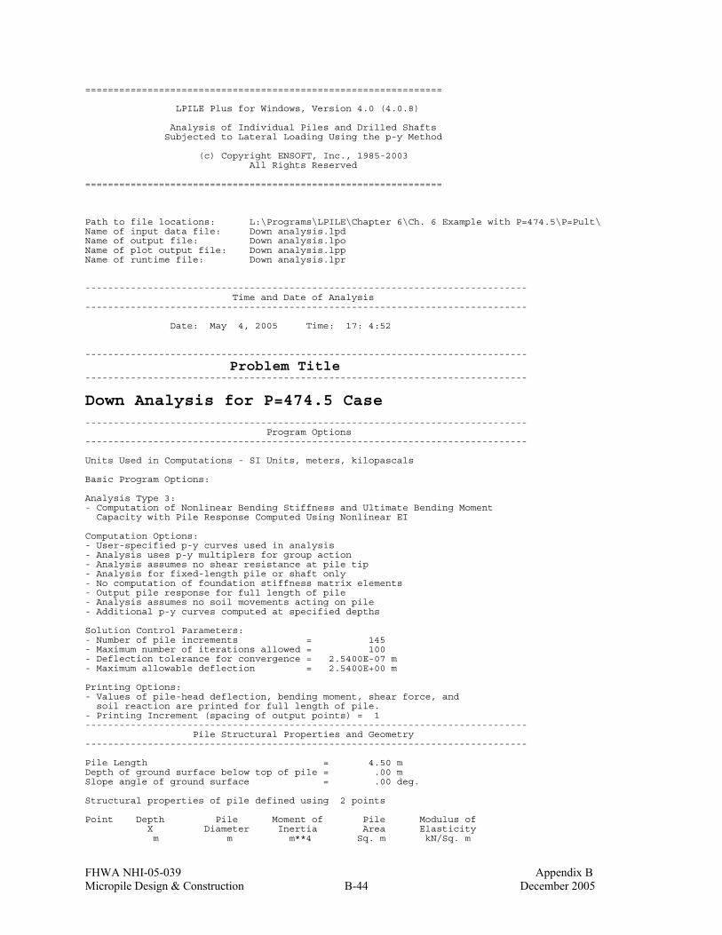
FHWA NHI-05-039 Appendix B Micropile Design & Construction B-44 December 2005
=============================================================== LPILE Plus for Windows, Version 4.0 (4.0.8) Analysis of Individual Piles and Drilled Shafts Subjected to Lateral Loading Using the p-y Method (c) Copyright ENSOFT, Inc., 1985-2003 All Rights Reserved =============================================================== Path to file locations: L:\Programs\LPILE\Chapter 6\Ch. 6 Example with P=474.5\P=Pult\ Name of input data file: Down analysis.lpd Name of output file: Down analysis.lpo Name of plot output file: Down analysis.lpp Name of runtime file: Down analysis.lpr ------------------------------------------------------------------------------ Time and Date of Analysis ------------------------------------------------------------------------------ Date: May 4, 2005 Time: 17: 4:52 ------------------------------------------------------------------------------
Problem Title ------------------------------------------------------------------------------
Down Analysis for P=474.5 Case ------------------------------------------------------------------------------ Program Options ------------------------------------------------------------------------------ Units Used in Computations - SI Units, meters, kilopascals Basic Program Options: Analysis Type 3: - Computation of Nonlinear Bending Stiffness and Ultimate Bending Moment Capacity with Pile Response Computed Using Nonlinear EI Computation Options: - User-specified p-y curves used in analysis - Analysis uses p-y multiplers for group action - Analysis assumes no shear resistance at pile tip - Analysis for fixed-length pile or shaft only - No computation of foundation stiffness matrix elements - Output pile response for full length of pile - Analysis assumes no soil movements acting on pile - Additional p-y curves computed at specified depths Solution Control Parameters: - Number of pile increments = 145 - Maximum number of iterations allowed = 100 - Deflection tolerance for convergence = 2.5400E-07 m - Maximum allowable deflection = 2.5400E+00 m Printing Options: - Values of pile-head deflection, bending moment, shear force, and soil reaction are printed for full length of pile. - Printing Increment (spacing of output points) = 1 ------------------------------------------------------------------------------ Pile Structural Properties and Geometry ------------------------------------------------------------------------------ Pile Length = 4.50 m Depth of ground surface below top of pile = .00 m Slope angle of ground surface = .00 deg. Structural properties of pile defined using 2 points Point Depth Pile Moment of Pile Modulus of X Diameter Inertia Area Elasticity m m m**4 Sq. m kN/Sq. m

FHWA NHI-05-039 Appendix B Micropile Design & Construction B-45 December 2005
----- --------- ----------- ---------- ---------- ----------- 1 0.0000 .17780000 1.0000 .024800 200000000.000 2 4.5000 .17780000 1.0000 .024800 200000000.000 Please note that because this analysis makes computations of ultimate moment capacity and pile response using nonlinear bending stiffness that the above values of moment of inertia and modulus of are not used for any computations other than total stress due to combined axial loading and bending. ------------------------------------------------------------------------------ Soil and Rock Layering Information ------------------------------------------------------------------------------ The soil profile is modelled using 1 layers Layer 1 is modelled using user-specied p-y curves Distance from top of pile to top of layer = .000 m Distance from top of pile to bottom of layer = 6.000 m (Depth of lowest layer extends 1.50 m below pile tip) ------------------------------------------------------------------------------ Effective Unit Weight of Soil vs. Depth ------------------------------------------------------------------------------ Distribution of effective unit weight of soil with depth is defined using 2 points Point Depth X Eff. Unit Weight No. m kN/ m**3 ----- ---------- ---------------- 1 .00 12.20000 2 6.00 12.20000 ------------------------------------------------------------------------------ Shear Strength of Soils ------------------------------------------------------------------------------ Distribution of shear strength parameters with depth defined using 0 points Point Depth X Cohesion c Angle of Friction E50 or RQD No. m kN/ m**2 Deg. k_rm % ----- -------- ---------- ------------------ ------ ------ Notes: (1) Cohesion = uniaxial compressive strength for rock materials. (2) Values of E50 are reported for clay strata. (3) Default values will be generated for E50 when input values are 0. (4) RQD and k_rm are reported only for weak rock strata. ------------------------------------------------------------------------------ p-y Modification Factors ------------------------------------------------------------------------------ Distribution of p-y multipliers with depth defined using 2 points Point Depth X p-mult y-mult No. m ----- ---------- ---------- ---------- 1 .000 1.0000 1.0000 2 6.000 1.0000 1.0000 ------------------------------------------------------------------------------ User-specified p-y Curves ------------------------------------------------------------------------------ User-specified p-y curves defined using 2 curves.

FHWA NHI-05-039 Appendix B Micropile Design & Construction B-46 December 2005
User-specified curve number 1 at depth = .000 m Point y p, No. m kN/ m ----- ---------- ---------- 1 .0000 .000 2 .0001 263.064 3 .0002 312.838 4 .0006 393.373 5 .0011 467.802 6 .0017 517.708 7 .0023 556.313 8 .0057 699.527 9 .0115 831.882 10 .0229 989.280 11 .0258 989.280 12 .0286 989.280 User-specified curve number 2 at depth = 6.000 m Point y p, No. m kN/ m ----- ---------- ---------- 1 .0000 .000 2 .0001 263.064 3 .0002 312.838 4 .0006 393.373 5 .0011 467.802 6 .0017 517.708 7 .0023 556.313 8 .0057 699.527 9 .0115 831.882 10 .0229 989.280 11 .0258 989.280 12 .0286 989.280 ------------------------------------------------------------------------------ Loading Type ------------------------------------------------------------------------------ Static loading criteria was used for computation of p-y curves ------------------------------------------------------------------------------ Pile-head Loading and Pile-head Fixity Conditions ------------------------------------------------------------------------------ Number of loads specified = 1 Load Case Number 1 Pile-head boundary conditions are Shear and Moment (BC Type 1) Shear force at pile head = 330.000 kN Bending moment at pile head = 76.200 m- kN Axial load at pile head = 474.500 kN Non-zero moment at pile head for this load case indicates the pile-head may rotate under the applied pile-head loading, but is not a free-head (zero moment) condition. ------------------------------------------------------------------------------ Output of p-y Curves at Specified Depths ------------------------------------------------------------------------------ p-y curves are generated and printed for verification at 2 depths. Depth Depth Below Pile Head Depth Below Ground Surface No. m m ----- --------------------- --------------------------

FHWA NHI-05-039 Appendix B Micropile Design & Construction B-47 December 2005
1 .000 .000 2 4.500 4.500 ------------------------------------------------------------------------------ Computations of Ultimate Moment Capacity and Nonlinear Bending Stiffness ------------------------------------------------------------------------------ Pile Description: The sectional shape is a circular shaft with steel casing. Outside Diameter = .1778 m Wall thickness of steel shell = .0115 m Cross-sectional area of shell = .00601 m**2 Moment of inertia of steel shell = 2.08692E-05 m**4 Material Properties: Compressive Strength of Concrete = 27600.000 kN/ m**2 Yield Stress of Reinforcement = 0. kN/ m**2 Steel shell or core yield stress = 552000. kN/ m**2 Modulus of Elasticity of Reinforcement = 200000000. kN/ m**2 Cover Thickness (edge to bar center) = .000 m Number of Reinforcing Bars = 10 Area of Single Bar = .00000 m**2 Number of Rows of Reinforcing Bars = 5 Ultimate Axial Squash Load Capacity = 3758.02 kN Distribution and Area of Steel Reinforcement Row Area of Distance to Number Reinforcement Centroidal Axis m**2 m ------ ------------- --------------- 1 .000000 .0736 2 .000000 .0455 3 .000000 .0000 4 .000000 -.0455 5 .000000 -.0736 Axial Thrust Force = 474.50 kN Bending Bending Bending Maximum Neutral Axis Moment Stiffness Curvature Strain Position kN-m kN-m2 rad/m m/m m ------------- ------------- ------------- ------------- ------------- 1.69826245 4792.874 .00035433 .00031727 .90691267 2.45303965 4792.862 .00051181 .00032949 .65527803 3.20781175 4792.848 .00066929 .00034172 .52206775 3.96257836 4792.833 .00082677 .00035395 .43960844 4.71733626 4792.814 .00098425 .00036619 .38354674 5.47208598 4792.792 .00114173 .00037843 .34295465 6.22682760 4792.770 .00129921 .00039068 .31220536 6.98155916 4792.746 .00145669 .00040293 .28810838 7.73628058 4792.720 .00161417 .00041519 .26871577 8.49098340 4792.688 .00177165 .00042746 .25277953 9.24568013 4792.659 .00192913 .00043973 .23944236 10.000 4792.625 .00208661 .00045201 .22812367 10.755 4792.590 .00224409 .00046429 .21839481 11.510 4792.551 .00240157 .00047658 .20994649 12.264 4792.509 .00255906 .00048888 .20253996 13.019 4792.470 .00271654 .00050118 .19599075 13.774 4792.426 .00287402 .00051348 .19016320 14.528 4792.379 .00303150 .00052579 .18494336 15.283 4792.326 .00318898 .00053812 .18024442 16.035 4791.716 .00334646 .00055042 .17597957 16.774 4787.090 .00350394 .00056260 .17206198 17.571 4799.091 .00366142 .00057505 .16855677 18.301 4792.220 .00381890 .00058745 .16532828 19.053 4791.556 .00397638 .00059979 .16233854 24.610 4771.704 .00515748 .00068957 .14520315 29.767 4696.101 .00633858 .00078032 .13460612 35.334 4698.840 .00751969 .00087092 .12731897 39.786 4572.710 .00870079 .00095706 .12149685 45.804 4635.195 .00988189 .00105014 .11776917 50.555 4569.762 .01106299 .00113526 .11411745

FHWA NHI-05-039 Appendix B Micropile Design & Construction B-48 December 2005
56.180 4588.341 .01224409 .00122769 .11176798 61.386 4572.465 .01342520 .00131523 .10946735 64.845 4439.494 .01460630 .00139171 .10678147 71.647 4538.208 .01578740 .00149414 .10614120 74.736 4404.370 .01696850 .00156633 .10380800 81.890 4511.946 .01814961 .00167053 .10354213 85.716 4434.167 .01933071 .00175060 .10206082 92.018 4486.089 .02051181 .00183074 .10075315 97.124 4477.213 .02169291 .00193616 .10075315 102.139 4465.294 .02287402 .00202929 .10021598 105.295 4377.229 .02405512 .00210249 .09890288 109.026 4320.217 .02523622 .00218134 .09793705 113.742 4305.584 .02641732 .00227957 .09779054 118.611 4297.758 .02759843 .00238148 .09779054 127.233 4420.944 .02877953 .00247762 .09758978 131.954 4404.252 .02996063 .00257166 .09733476 136.319 4377.388 .03114173 .00266730 .09715027 140.277 4339.870 .03232283 .00276706 .09710686 143.850 4293.538 .03350394 .00287126 .09719911 147.136 4242.066 .03468504 .00297869 .09737816 150.123 4185.651 .03586614 .00308557 .09753009 152.748 4123.053 .03704724 .00319502 .09774171 152.748 3995.667 .03822835 .00329874 .09779054 152.748 3875.917 .03940945 .00340066 .09779054 154.387 3803.521 .04059055 .00350258 .09779054 155.966 3733.787 .04177165 .00360450 .09779054 157.340 3663.103 .04295276 .00370642 .09779054 158.551 3592.498 .04413386 .00380833 .09779054 Ultimate Moment Capacity at a Concrete Strain of 0.003 = 147.732 m- kN p-y Curve Computed by Interpolation from User-input Curves Soil Layer Number = 1 Depth below ground surface = .000 m Depth below pile head = .000 m p-multiplier = 1.00000 y-multiplier = 1.00000 y, m p, kN/ m ---------------- ---------------- .0000 .000 .0010 452.916 .0011 468.738 .0022 551.327 .0033 599.856 .0044 646.664 .0056 693.472 .0067 721.605 .0078 746.964 .0089 772.322 .0100 797.681 .0111 823.039 .0122 841.875 .0133 857.218 .0356 989.280 .0667 989.280 .0889 989.280 p-y Curve Computed by Interpolation from User-input Curves Soil Layer Number = 1 Depth below ground surface = 4.500 m Depth below pile head = 4.500 m p-multiplier = 1.00000 y-multiplier = 1.00000 y, m p, kN/ m ---------------- ---------------- .0000 .000 .0010 452.916 .0011 468.738 .0022 551.327 .0033 599.856 .0044 646.664 .0056 693.472 .0067 721.605

FHWA NHI-05-039 Appendix B Micropile Design & Construction B-49 December 2005
.0078 746.964 .0089 772.322 .0100 797.681 .0111 823.039 .0122 841.875 .0133 857.218 .0356 989.280 .0667 989.280 .0889 989.280 ------------------------------------------------------------------------------ Computed Values of Load Distribution and Deflection for Lateral Loading for Load Case Number 1 ------------------------------------------------------------------------------ Pile-head boundary conditions are Shear and Moment (BC Type 1) Specified shear force at pile head = 330.000 kN Specified bending moment at pile head = 76.200 m- kN Specified axial load at pile head = 474.500 kN Non-zero moment for this load case indicates the pile-head may rotate under the applied pile-head loading, but is not a free-head (zero moment )condition. Depth Deflect. Moment Shear Slope Total Flx. Rig. Soil Res X y M V S Stress EI p m m kN- m kN Rad. kN/ m**2 kN- m**2 kN/ m -------- --------- --------- --------- --------- --------- --------- --------- 0.000 .014998 76.2000 330.0 -.029550 1.91E+04 4440.259 -880.191 .03103 .014089 86.4487 302.9 -.028982 1.91E+04 4440.259 -867.643 .06207 .013199 95.8529 276.1 -.028344 1.91E+04 4440.259 -855.355 .09310 .012330 104.4 249.8 -.027641 1.91E+04 4402.137 -843.353 .124 .011484 112.2 223.8 -.026869 1.91E+04 4310.471 -831.519 .155 .010662 119.1 198.3 -.026036 1.91E+04 4304.934 -812.777 .186 .009868 125.2 173.3 -.025165 1.91E+04 4392.860 -794.642 .217 .009100 130.6 148.9 -.024263 1.91E+04 4409.035 -777.134 .248 .008362 135.2 125.1 -.023324 1.91E+04 4384.290 -760.277 .279 .007653 139.1 101.7 -.022350 1.91E+04 4351.532 -744.098 .310 .006975 142.2 78.8937 -.021343 1.91E+04 4315.407 -728.621 .341 .006328 144.6 56.5102 -.020308 1.91E+04 4282.247 -713.869 .372 .005714 146.3 34.5731 -.019250 1.91E+04 4255.618 -699.859 .403 .005133 147.3 13.2288 -.018178 1.91E+04 4239.142 -675.661 .434 .004586 147.6 -7.3822 -.017097 1.91E+04 4232.741 -652.603 .466 .004072 147.3 -27.2996 -.016017 1.91E+04 4238.305 -630.961 .497 .003592 146.4 -46.5672 -.014943 1.91E+04 4253.508 -610.730 .528 .003144 144.9 -65.2286 -.013883 1.91E+04 4277.471 -591.895 .559 .002730 142.8 -83.3268 -.012843 1.91E+04 4307.612 -574.434 .590 .002347 140.1 -100.9 -.011828 1.91E+04 4341.609 -558.318 .621 .001996 136.9 -117.9 -.010842 1.91E+04 4372.296 -536.749 .652 .001674 133.1 -134.2 -.009887 1.91E+04 4397.257 -515.586 .683 .001382 128.8 -149.8 -.008964 1.91E+04 4415.342 -491.280 .714 .001118 124.1 -164.8 -.008072 1.91E+04 4376.125 -469.311 .745 8.81E-04 118.8 -178.8 -.007203 1.91E+04 4300.982 -435.230 .776 6.71E-04 113.2 -191.8 -.006366 1.91E+04 4307.350 -403.939 .807 4.86E-04 107.1 -203.8 -.005577 1.91E+04 4349.681 -370.427 .838 3.25E-04 100.7 -214.8 -.004845 1.91E+04 4468.752 -337.979 .869 1.85E-04 93.9248 -224.8 -.004170 1.91E+04 4482.780 -305.510 .900 6.59E-05 86.8575 -232.2 -.003542 1.91E+04 4443.643 -173.263 .931 -3.46E-05 79.6145 -233.5 -.002963 1.91E+04 4478.130 91.121 .962 -1.18E-04 72.4510 -227.9 -.002437 1.91E+04 4504.740 271.981 .993 -1.86E-04 65.5422 -218.9 -.001959 1.91E+04 4449.767 305.793 1.024 -2.40E-04 58.9212 -209.2 -.001531 1.91E+04 4579.999 320.786 1.055 -2.81E-04 52.6032 -199.1 -.001153 1.91E+04 4576.541 329.109 1.086 -3.11E-04 46.5970 -188.8 -8.18E-04 1.91E+04 4624.438 335.201 1.117 -3.32E-04 40.9090 -178.3 -5.23E-04 1.91E+04 4584.479 339.339 1.148 -3.44E-04 35.5438 -167.8 -2.67E-04 1.91E+04 4693.099 341.745 1.179 -3.48E-04 30.5042 -157.1 -4.89E-05 1.91E+04 4696.464 342.682 1.210 -3.47E-04 25.7917 -146.5 1.36E-04 1.91E+04 4754.616 342.359 1.241 -3.40E-04 21.4065 -135.9 2.90E-04 1.91E+04 4783.170 340.984 1.272 -3.29E-04 17.3477 -125.4 4.15E-04 1.91E+04 4795.724 338.741 1.303 -3.14E-04 13.6134 -114.9 5.15E-04 1.91E+04 4792.435 335.796 1.334 -2.97E-04 10.2013 -104.5 5.93E-04 1.91E+04 4792.615 332.301 1.366 -2.77E-04 7.1083 -94.2721 6.49E-04 1.91E+04 4792.742 328.392 1.397 -2.56E-04 4.3309 -84.1457 6.86E-04 1.91E+04 4792.823 324.196 1.428 -2.35E-04 1.8653 -74.1523 7.06E-04 1.91E+04 4792.871 319.825 1.459 -2.13E-04 -.2925 -64.2957 7.11E-04 1.91E+04 4792.874 315.378 1.490 -1.91E-04 -2.1464 -54.6200 7.03E-04 1.91E+04 4792.867 308.163 1.521 -1.69E-04 -3.7034 -45.2231 6.84E-04 1.91E+04 4792.838 297.413

FHWA NHI-05-039 Appendix B Micropile Design & Construction B-50 December 2005
1.552 -1.48E-04 -4.9735 -36.1541 6.56E-04 1.91E+04 4792.806 287.034 1.583 -1.28E-04 -5.9668 -27.3995 6.20E-04 1.91E+04 4792.778 277.152 1.614 -1.10E-04 -6.6925 -18.9423 5.79E-04 1.91E+04 4792.755 267.867 1.645 -9.23E-05 -7.1596 -11.0162 5.35E-04 1.91E+04 4792.740 242.930 1.676 -7.65E-05 -7.3920 -4.1248 4.87E-04 1.91E+04 4792.732 201.179 1.707 -6.21E-05 -7.4299 1.5314 4.39E-04 1.91E+04 4792.731 163.335 1.738 -4.92E-05 -7.3099 6.0742 3.92E-04 1.91E+04 4792.735 129.420 1.769 -3.78E-05 -7.0645 9.6244 3.45E-04 1.91E+04 4792.743 99.369 1.800 -2.78E-05 -6.7227 12.2999 3.01E-04 1.91E+04 4792.754 73.052 1.831 -1.91E-05 -6.3099 14.2138 2.58E-04 1.91E+04 4792.768 50.289 1.862 -1.17E-05 -5.8480 15.4730 2.19E-04 1.91E+04 4792.781 30.862 1.893 -5.52E-06 -5.3559 16.1773 1.83E-04 1.91E+04 4792.796 14.526 1.924 -3.89E-07 -4.8493 16.4186 1.50E-04 1.91E+04 4792.810 1.022 1.955 3.77E-06 -4.3412 16.2805 1.20E-04 1.91E+04 4792.823 -9.919 1.986 7.06E-06 -3.8423 15.8386 9.35E-05 1.91E+04 4792.835 -18.564 2.017 9.57E-06 -3.3609 15.1598 7.01E-05 1.91E+04 4792.845 -25.179 2.048 1.14E-05 -2.9034 14.3033 4.99E-05 1.91E+04 4792.854 -30.017 2.079 1.27E-05 -2.4746 13.3205 3.24E-05 1.91E+04 4792.862 -33.320 2.110 1.34E-05 -2.0776 12.2555 1.77E-05 1.91E+04 4792.868 -35.314 2.141 1.38E-05 -1.7144 11.1456 5.43E-06 1.91E+04 4792.874 -36.211 2.172 1.38E-05 -1.3860 10.0220 -4.61E-06 1.91E+04 4792.874 -36.201 2.203 1.35E-05 -1.0922 8.9100 -1.26E-05 1.91E+04 4792.874 -35.459 2.234 1.30E-05 -.8326 7.8301 -1.89E-05 1.91E+04 4792.874 -34.139 2.266 1.23E-05 -.6057 6.7979 -2.35E-05 1.91E+04 4792.874 -32.379 2.297 1.15E-05 -.4099 5.8253 -2.68E-05 1.91E+04 4792.874 -30.299 2.328 1.06E-05 -.2433 4.9207 -2.89E-05 1.91E+04 4792.874 -28.002 2.359 9.72E-06 -.1037 4.0893 -3.00E-05 1.91E+04 4792.874 -25.576 2.390 8.78E-06 1.14E-02 3.3340 -3.03E-05 1.91E+04 4792.874 -23.096 2.421 7.84E-06 .1042 2.6556 -3.00E-05 1.91E+04 4792.874 -20.622 2.452 6.92E-06 .1771 2.0532 -2.91E-05 1.91E+04 4792.874 -18.202 2.483 6.04E-06 .2325 1.5244 -2.77E-05 1.91E+04 4792.874 -15.877 2.514 5.20E-06 .2725 1.0658 -2.61E-05 1.91E+04 4792.874 -13.674 2.545 4.42E-06 .2994 .6734 -2.42E-05 1.91E+04 4792.874 -11.615 2.576 3.69E-06 .3150 .3424 -2.23E-05 1.91E+04 4792.874 -9.715 2.607 3.03E-06 .3213 6.78E-02 -2.02E-05 1.91E+04 4792.874 -7.981 2.638 2.44E-06 .3198 -.1556 -1.81E-05 1.91E+04 4792.874 -6.417 2.669 1.91E-06 .3122 -.3331 -1.61E-05 1.91E+04 4792.874 -5.022 2.700 1.44E-06 .2996 -.4699 -1.41E-05 1.91E+04 4792.874 -3.792 2.731 1.03E-06 .2834 -.5710 -1.22E-05 1.91E+04 4792.874 -2.721 2.762 6.84E-07 .2646 -.6411 -1.04E-05 1.91E+04 4792.874 -1.799 2.793 3.87E-07 .2439 -.6848 -8.79E-06 1.91E+04 4792.874 -1.018 2.824 1.39E-07 .2223 -.7063 -7.28E-06 1.91E+04 4792.874 -.364770 2.855 -6.48E-08 .2003 -.7093 -5.91E-06 1.91E+04 4792.874 .170530 2.886 -2.28E-07 .1785 -.6973 -4.68E-06 1.91E+04 4792.874 .599935 2.917 -3.55E-07 .1572 -.6735 -3.60E-06 1.91E+04 4792.874 .934996 2.948 -4.51E-07 .1368 -.6406 -2.64E-06 1.91E+04 4792.874 1.187 2.979 -5.20E-07 .1175 -.6010 -1.82E-06 1.91E+04 4792.874 1.367 3.010 -5.64E-07 9.95E-02 -.5567 -1.12E-06 1.91E+04 4792.874 1.484 3.041 -5.89E-07 8.30E-02 -.5096 -5.27E-07 1.91E+04 4792.874 1.549 3.072 -5.97E-07 6.79E-02 -.4612 -3.85E-08 1.91E+04 4792.874 1.570 3.103 -5.91E-07 5.43E-02 -.4127 3.57E-07 1.91E+04 4792.874 1.555 3.134 -5.75E-07 4.23E-02 -.3651 6.70E-07 1.91E+04 4792.874 1.512 3.166 -5.50E-07 3.17E-02 -.3192 9.09E-07 1.91E+04 4792.874 1.446 3.197 -5.18E-07 2.24E-02 -.2757 1.08E-06 1.91E+04 4792.874 1.363 3.228 -4.82E-07 1.45E-02 -.2348 1.20E-06 1.91E+04 4792.874 1.269 3.259 -4.44E-07 7.82E-03 -.1970 1.28E-06 1.91E+04 4792.874 1.167 3.290 -4.03E-07 2.25E-03 -.1625 1.31E-06 1.91E+04 4792.874 1.060 3.321 -3.62E-07 -2.30E-03 -.1312 1.31E-06 1.91E+04 4792.874 .952991 3.352 -3.22E-07 -5.93E-03 -.1033 1.28E-06 1.91E+04 4792.874 .846726 3.383 -2.83E-07 -8.75E-03 -7.86E-02 1.23E-06 1.91E+04 4792.874 .743596 3.414 -2.45E-07 -1.08E-02 -5.71E-02 1.17E-06 1.91E+04 4792.874 .645089 3.445 -2.10E-07 -1.23E-02 -3.85E-02 1.10E-06 1.91E+04 4792.874 .552316 3.476 -1.77E-07 -1.33E-02 -2.27E-02 1.01E-06 1.91E+04 4792.874 .466057 3.507 -1.47E-07 -1.38E-02 -9.44E-03 9.26E-07 1.91E+04 4792.874 .386811 3.538 -1.20E-07 -1.39E-02 1.45E-03 8.37E-07 1.91E+04 4792.874 .314838 3.569 -9.51E-08 -1.37E-02 1.02E-02 7.47E-07 1.91E+04 4792.874 .250203 3.600 -7.33E-08 -1.33E-02 1.71E-02 6.60E-07 1.91E+04 4792.874 .192806 3.631 -5.41E-08 -1.27E-02 2.23E-02 5.76E-07 1.91E+04 4792.874 .142423 3.662 -3.75E-08 -1.19E-02 2.60E-02 4.97E-07 1.91E+04 4792.874 .098729 3.693 -2.33E-08 -1.11E-02 2.85E-02 4.22E-07 1.91E+04 4792.874 .061326 3.724 -1.13E-08 -1.01E-02 2.99E-02 3.54E-07 1.91E+04 4792.874 .029765 3.755 -1.36E-09 -9.20E-03 3.04E-02 2.91E-07 1.91E+04 4792.874 .003565 3.786 6.75E-09 -8.26E-03 3.02E-02 2.35E-07 1.91E+04 4792.874 -.017769 3.817 1.32E-08 -7.33E-03 2.94E-02 1.84E-07 1.91E+04 4792.874 -.034735 3.848 1.82E-08 -6.44E-03 2.81E-02 1.39E-07 1.91E+04 4792.874 -.047825 3.879 2.19E-08 -5.59E-03 2.65E-02 1.01E-07 1.91E+04 4792.874 -.057509 3.910 2.44E-08 -4.80E-03 2.46E-02 6.69E-08 1.91E+04 4792.874 -.064237 3.941 2.60E-08 -4.07E-03 2.26E-02 3.82E-08 1.91E+04 4792.874 -.068428 3.972 2.68E-08 -3.40E-03 2.04E-02 1.40E-08 1.91E+04 4792.874 -.070469 4.003 2.69E-08 -2.80E-03 1.82E-02 -6.09E-09 1.91E+04 4792.874 -.070712 4.034 2.64E-08 -2.27E-03 1.60E-02 -2.25E-08 1.91E+04 4792.874 -.069474

FHWA NHI-05-039 Appendix B Micropile Design & Construction B-51 December 2005
4.066 2.55E-08 -1.81E-03 1.39E-02 -3.57E-08 1.91E+04 4792.874 -.067036 4.097 2.42E-08 -1.41E-03 1.19E-02 -4.61E-08 1.91E+04 4792.874 -.063644 4.128 2.26E-08 -1.07E-03 9.97E-03 -5.41E-08 1.91E+04 4792.874 -.059508 4.159 2.08E-08 -7.85E-04 8.20E-03 -6.01E-08 1.91E+04 4792.874 -.054808 4.190 1.89E-08 -5.56E-04 6.58E-03 -6.45E-08 1.91E+04 4792.874 -.049693 4.221 1.68E-08 -3.75E-04 5.12E-03 -6.75E-08 1.91E+04 4792.874 -.044283 4.252 1.47E-08 -2.37E-04 3.83E-03 -6.95E-08 1.91E+04 4792.874 -.038676 4.283 1.25E-08 -1.35E-04 2.72E-03 -7.07E-08 1.91E+04 4792.874 -.032943 4.314 1.03E-08 -6.58E-05 1.79E-03 -7.13E-08 1.91E+04 4792.874 -.027138 4.345 8.10E-09 -2.23E-05 1.04E-03 -7.16E-08 1.91E+04 4792.874 -.021299 4.376 5.87E-09 6.32E-07 4.66E-04 -7.17E-08 1.91E+04 4792.874 -.015448 4.407 3.65E-09 8.71E-06 7.74E-05 -7.16E-08 1.91E+04 4792.874 -.009597 4.438 1.43E-09 7.55E-06 -1.30E-04 -7.16E-08 1.91E+04 4792.874 -.003751 4.469 -7.95E-10 2.77E-06 -1.56E-04 -7.15E-08 1.91E+04 4792.874 .002091 4.500 -3.01E-09 0.0 0.0 -7.15E-08 1.91E+04 4792.874 .007931 Please note that because this analysis makes computations of ultimate moment capacity and pile response using nonlinear bending stiffness that the above values of total stress due to combined axial stress and bending may not be representative of actual conditions. Output Verification: Computed forces and moments are within specified convergence limits. Output Summary for Load Case No. 1: Pile-head deflection = .01499829 m Computed slope at pile head = -.02954991 Maximum bending moment = 147.640 kN- m Maximum shear force = 330.000 kN Depth of maximum bending moment = .43448276 m Depth of maximum shear force = 0.000 m Number of iterations = 22 Number of zero deflection points = 5 ------------------------------------------------------------------------------ Summary of Pile-head Response ------------------------------------------------------------------------------ Definition of symbols for pile-head boundary conditions: y = pile-head displacment, m M = pile-head moment, kN- m V = pile-head shear force, kN S = pile-head slope, radians R = rotational stiffness of pile-head, m- kN/rad BC Boundary Boundary Axial Pile Head Maximum Maximum Type Condition Condition Load Deflection Moment Shear 1 2 kN m m- kN kN ---- ------------ ------------ ----------- ----------- ----------- ----------- 1 V = 330.000 M = 76.200 474.5000 .014998 147.6397 330.0000

FHWA NHI-05-039 Appendix B Micropile Design & Construction B-52 December 2005
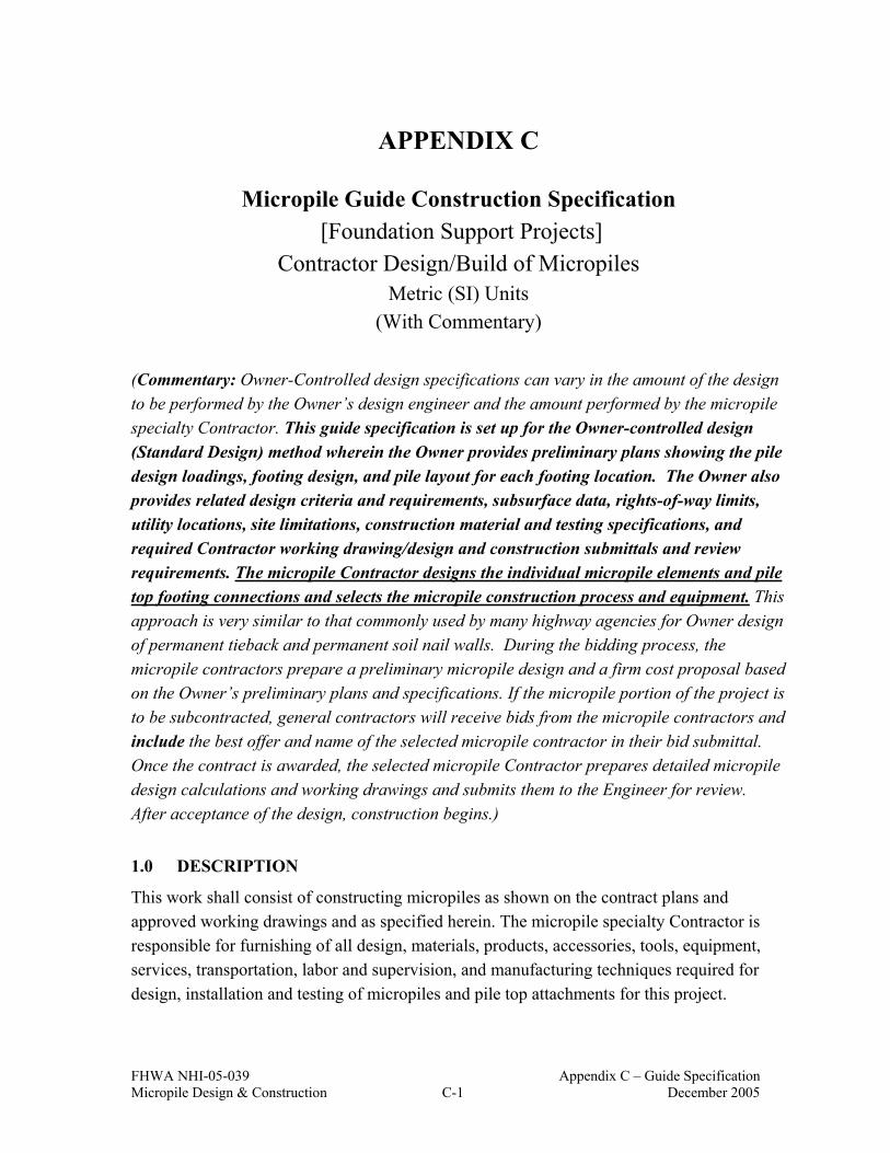
FHWA NHI-05-039 Appendix C – Guide Specification Micropile Design & Construction C-1 December 2005
APPENDIX C
Micropile Guide Construction Specification [Foundation Support Projects]
Contractor Design/Build of Micropiles
Metric (SI) Units (With Commentary)
(Commentary: Owner-Controlled design specifications can vary in the amount of the design to be performed by the Owner’s design engineer and the amount performed by the micropile specialty Contractor. This guide specification is set up for the Owner-controlled design (Standard Design) method wherein the Owner provides preliminary plans showing the pile design loadings, footing design, and pile layout for each footing location. The Owner also provides related design criteria and requirements, subsurface data, rights-of-way limits, utility locations, site limitations, construction material and testing specifications, and required Contractor working drawing/design and construction submittals and review requirements. The micropile Contractor designs the individual micropile elements and pile top footing connections and selects the micropile construction process and equipment. This approach is very similar to that commonly used by many highway agencies for Owner design of permanent tieback and permanent soil nail walls. During the bidding process, the micropile contractors prepare a preliminary micropile design and a firm cost proposal based on the Owner’s preliminary plans and specifications. If the micropile portion of the project is to be subcontracted, general contractors will receive bids from the micropile contractors and include the best offer and name of the selected micropile contractor in their bid submittal. Once the contract is awarded, the selected micropile Contractor prepares detailed micropile design calculations and working drawings and submits them to the Engineer for review. After acceptance of the design, construction begins.)
1.0 DESCRIPTION
This work shall consist of constructing micropiles as shown on the contract plans and approved working drawings and as specified herein. The micropile specialty Contractor is responsible for furnishing of all design, materials, products, accessories, tools, equipment, services, transportation, labor and supervision, and manufacturing techniques required for design, installation and testing of micropiles and pile top attachments for this project.

FHWA NHI-05-039 Appendix C – Guide Specification Micropile Design & Construction C-2 December 2005
The selected micropile Contractor shall select the micropile type, size, pile top attachment, installation means and methods, estimate the ground-grout bond value and determine the required bond length and final micropile diameter. The micropile Contractor shall design and install micropiles that will develop the load capacities indicated on the contract plans. The micropile load capacities shall be verified by verification and proof load testing as required and must meet the test acceptance criteria specified herein. Where the imperative mood is used within this specification, “The Contractor shall” is implied. (Commentary: Successful design and installation of high-quality micropiles require experienced Contractors having the necessary specialty drilling and grouting equipment and expertise and experienced work crews. The most important section of the specifications to be enforced by the Owner deals with the experience qualifications of the micropile Contractor. Failure to enforce the specified experience qualifications opens the door for inexperienced Contractors trying to cut costs. The results often are inferior workmanship, project delays, and project claims that, more often than not, substantially increase project costs. Results like these often discourage project Owners from implementing new technology, and draws them back to more traditional methods at any cost. This can be avoided with the proper specification implementation and, as importantly, enforcement to ensure a mutually successful project.) 1.1 Micropile Contractor’s Experience Requirements And Submittal. The micropile Contractor shall be experienced in the construction and load testing of micropiles and have successfully constructed at least 5 projects in the last 5 years involving construction totaling at least 100 micropiles of similar capacity to those required in these plans and specifications. The Contractor shall have previous micropile drilling and grouting experience in soil/rock similar to project conditions. The Contractor shall submit construction details, structural details and load test results for at least three previous successful micropile load tests from different projects of similar scope to this project. The Contractor shall assign an Engineer to supervise the work with experience on at least 3 projects of similar scope to this project completed over the past 5 years. The Contractor shall not use consultants or manufacturers’ representatives to satisfy the supervising Engineer requirements of this section. The on-site foremen and drill rig operators shall also have

FHWA NHI-05-039 Appendix C – Guide Specification Micropile Design & Construction C-3 December 2005
experience on at least 3 projects over the past 5 years installing micropiles of equal or greater capacity than required in these plans and specifications. The micropiles shall be designed by a Registered Professional Engineer with experience in the design of at least 3 successfully completed micropile projects over the past 5 years, with micropiles of similar capacity to those required in these plans and specifications. The micropile design engineer may be either an employee of the Contractor or a separate Consultant design engineer meeting the stated experience requirements. (Commentary: If the Owner prepares a fully detailed design, this paragraph can be deleted). At least 45 calendar days before the planned start of micropile construction, the Contractor shall submit 5 copies of the completed project reference list and a personnel list. The project reference list shall include a brief project description with the owner's name and current phone number and load test reports. The personnel list shall identify the micropile system design engineer (if applicable), supervising project Engineer, drill rig operators, and on-site foremen to be assigned to the project. The personnel list shall contain a summary of each individual's experience and be complete enough for the Engineer to determine whether each individual satisfies the required qualifications. The Engineer will approve or reject the Contractor's qualifications within 15 calendar days after receipt of a complete submission. Additional time required due to incomplete or unacceptable submittals will not be cause for time extension or impact or delay claims. All costs associated with incomplete or unacceptable submittals shall be borne by the Contractor. Work shall not be started, nor materials ordered, until the Engineer’s written approval of the Contractor's experience qualifications is given. The Engineer may suspend the Work if the Contractor uses non-approved personnel. If work is suspended, the Contractor shall be fully liable for all resulting costs and no adjustment in contract time will result from the suspension. 1.2 Related Specifications (Commentary: Engineer to specify all related specifications.) 1.3 Definitions (Commentary: Engineer to specify any additional definitions.) Admixture: Substance added to the grout to control bleed and/or shrinkage, improve
flowability, reduce water content, or retard setting time.

FHWA NHI-05-039 Appendix C – Guide Specification Micropile Design & Construction C-4 December 2005
Alignment Load (AL): A minimum initial load (no greater than 10 percent of the Design Load) applied to micropile during testing to keep the testing equipment correctly positioned.
Bond Length: The length of the micropile that is bonded to the ground and used to transfer the applied axial loads to the surrounding soil or rock.
Bond-breaker: A sleeve placed over the steel reinforcement to prevent load transfer. Casing: Steel tube introduced during the drilling process in overburden soil to temporarily
stabilize the drill hole. This is usually withdrawn as the pile is grouted, although in certain types of micropiles, some casing is permanently left in place to provide added pile reinforcement.
Centralizer: A device to support and position the reinforcing steel in the drill hole and/or casing so that a minimum grout cover is provided.
Contractor: The person/firm responsible for performing the micropile work. Coupler: The means by which load capacity can be transmitted from one partial length of
reinforcement to another. Creep Movement: The movement that occurs during the creep test of a micropile under a
constant load. Design Load (DL): The maximum load expected to be applied to the micropile during its
service life. Encapsulation: A corrugated or deformed tube protecting the reinforcing steel against
corrosion. Engineer: The Owner or Owner’s authorized agent. Free (unbonded) length: The designed length of the micropile that is not bonded to the
surrounding ground or grout. Micropile: A small-diameter, bored, cast-in-place composite pile, in which the applied load
is resisted by steel reinforcement, cement grout and frictional grout/ground bond. Maximum Test Load: The maximum load to which the micropile is subjected during
testing. Ultimate Grout-to-Ground Bond Values: The estimated ultimate geotechnical unit grout-
to-ground bond strength selected for use in design. Overburden: Material, natural or placed, that may require cased drilling methods to provide
an open borehole to underlying strata. Post-grouting: The injection of additional grout into the load transfer length of a micropile
after the primary grout has set. Also known as regrouting or secondary grouting. Primary Grout: Portland-cement-based grout injected into the micropile hole prior to or
after the installation of the reinforcement to direct the load transfer to the surrounding ground along the micropile.

FHWA NHI-05-039 Appendix C – Guide Specification Micropile Design & Construction C-5 December 2005
Proof Load Test: Incremental loading of a production micropile, recording the total movement at each increment.
Reinforcement: The steel component of the micropile that accepts and/or resists applied loadings.
Sheathing: Smooth or corrugated piping or tubing that protects the reinforcing steel against corrosion.
Spacer: A device to separate elements of a multiple-element reinforcement. Verification Load Test: Pile load test performed to verify the design of the pile system and
the construction methods proposed, prior to installation of production piles.
1.4 Referenced Codes and Standards. The following publications form a part of this specification to the extent indicated by the references. The latest publication as of the issue date of this specification shall govern, unless indicated otherwise.
1.4.1 American Society for Testing and Materials (ASTM) American Association of State Highway and Transportation Officials (AASHTO)
ASTM AASHTO SPECIFICATION / TEST
A36, A572 M183, M223 Structural Steel
A82 M55 Cold-Drawn Steel Wire for Concrete Reinforcement
A252 – Welded and Seamless Steel Pipe Piles
A615 M31 Deformed and Plain Billet Steel Bars for Concrete Reinforcement
A722 M275 Uncoated High-Strength Steel Bar for Prestressing Concrete
A775 – Epoxy -Coated Reinforcing Steel Bars
A934 – Epoxy-Coated Prefabricated Steel Reinforcing Bars
C 33 M80 Concrete Aggregates
C 109 T106 Compressive Strength of Hydraulic Cement Mortar
C 188 T133 Density of Hydraulic Cement
C 144 M45 Aggregate for Masonry Mortar
C 150 M 85 Portland Cement
C 494 M194 Chemical Admixtures for Concrete
D 1143 – Method of Testing Piles Under Static Axial Compressive Load
D 1784 – Polyvinyl Chloride (PVC) Pipe (Class 13464-B)
D 3350 M 252 Polyethylene Corrugated Tubing
D 3689 – Method of Testing Individual Piles Under Static Axial Tensile Load
D 3966 Standard Test Method for Piles Under Lateral Load
– T 26 Quality of Water to be Used in Concrete

FHWA NHI-05-039 Appendix C – Guide Specification Micropile Design & Construction C-6 December 2005
1.4.2 American Welding Society (AWS) D1.1 Structural Welding Code-Steel D1.2 Structural Welding Code-Reinforcing Steel
1.4.3 American Petroleum Institute (API) 5CT (N-80) Specification for casing and tubing RP 13B-1 Recommended Practice – Standard Procedure for Field Testing
Water Based Drilling Fluids
1.5 Available Information. Available information developed by the Owner, or by the Owner’s duly authorized representative include the following items: 1. Plans prepared by ___________ , dated __________. 2. Geotechnical Report No.(s) ________ titled __________, dated__________. (Commentary: The subsurface conditions expected can significantly impact the contractor's choice of procedures, methods, or equipment, the bidding process, and contract administration. Experience has proven that use of a geotechnical summary is advantageous toward achieving a successful contract. It is recommended that advisory wording be inserted into the contract special provisions to "red flag" the conditions to bidders. Such a summary may become part of the contract special provisions, making it a legal part of the contract documents. The purpose is to alert and be fair to bidders, and thus prevent/minimize differing site condition construction claims and dispute.)
1.6 Construction Site Survey Before bidding the Work, the Contractor shall review the available subsurface information and visit the site to assess the site geometry, equipment access conditions, and location of existing structures and above ground facilities. The Contractor is responsible for field locating and verifying the location of all utilities shown on the plans prior to starting the Work. Maintain uninterrupted service for those utilities designated to remain in service throughout the Work. Notify the Engineer of any utility locations different from shown on the plans that may require micropile relocations or structure design modification. Subject to the Engineer’s approval, additional cost to the Contractor due to micropile relocations and/or structure design modification resulting from utility locations different from shown on the plans, will be paid as Extra Work. (Commentary: The location of both active and abandoned buried utilities within the ground mass to receive micropiles can have a profound impact on the design and construction of the

FHWA NHI-05-039 Appendix C – Guide Specification Micropile Design & Construction C-7 December 2005
micropiles. Careful consideration of the presence and location of all utilities is required for successful design and installation of micropiles.) Prior to start of any micropile construction activity, the Contractor and Engineer shall jointly inspect the site to observe and document the pre-construction condition of the site, existing structures and facilities.
1.7 Micropile Design Requirements. The micropiles shall be designed to meet the specified loading conditions, as shown on the contract plans and approved working drawings. Design the micropiles and pile top to footing connections using the procedures contained in the FHWA “Micropile Design and Construction”, Report No. FHWA NHI-05-039. The required geotechnical factors of safety shall be in accord with the FHWA manual, unless specified otherwise. Estimated soil/rock design shear strength parameters, unit weights, applied foundation loadings, slope and external surcharge loads, corrosion protection requirements, known utility locations, easements, right-of-ways and other applicable design criteria will be as shown on the plans or specified herein. Structural design of any individual micropile structure elements not covered in the FHWA manual shall be by the service load design method in conformance with appropriate articles of the most current Edition of the AASHTO Standard Specifications for Highway Bridges, including current interim specifications. Where required as shown on the contract plans, corrosion protection of the internal steel reinforcing bars, consisting of either encapsulation, epoxy coating, or grout, shall be provided in accordance with Materials Section 2.0. Where permanent casing is used for a portion of the micropile, encapsulation shall extend at least 1.5 m into the casing. (Commentary: The previous paragraph is not comprehensive. Corrosion protection requirements need to be evaluated on a project-specific basis and detailed specifications and drawings depicting the corrosion protection requirements should be provided.) (Commentary: When installation of micropiles provides additional support for existing structures, such as for seismic retrofit or underpinning applications, the structural designer should add appropriate specification verbiage and design criteria into this specification to cover the penetration of the existing structural elements and the top of pile anchorage to the existing structure.)

FHWA NHI-05-039 Appendix C – Guide Specification Micropile Design & Construction C-8 December 2005
1.7.1 Micropile Design Submittals. At least 21 calendar days before the planned start of micropile structure construction, submit complete design calculations and working drawings to the Engineer for review and approval. Include all details, dimensions, quantities, ground profiles, and cross-sections necessary to construct the micropile structure. Verify the limits of the micropile structure and ground survey data before preparing the detailed working drawings. The drawings and calculations shall be signed and sealed by the contractor’s Professional Engineer or by the Consultant designer’s Professional Engineer (if applicable), previously approved by the owner’s Engineer. If the micropile contractor uses a consultant design engineer to prepare the design, the micropile contractor shall still have overall contract responsibility for both the design and the construction.
1.7.2 Design Calculations. Design calculations shall include, but not be limited to, the following items: 1. A written summary report which describes the overall micropile design. 2. Applicable code requirements and design references. 3. Micropile structure critical design cross-section(s) geometry including soil/rock strata
and piezometric levels and location, magnitude and direction of design applied loadings, including slope or external surcharge loads.
4. Design criteria including, soil/rock shear strengths (friction angle and cohesion), unit weights, and ground-grout bond values and micropile drillhole diameter assumptions for each soil/rock strata.
5. Factors of safety and allowable stresses used in the design on the ground-grout bond values, surcharges, soil/rock and material unit weights, steel, grout, and concrete materials.
6. Seismic design earthquake acceleration coefficient. 7. Design calculation sheets (both static and seismic) with the project number, micropile
structure location, designation, date of preparation, initials of designer and checker, and page number at the top of each page. Provide an index page with the design calculations.
8. Design notes including an explanation of any symbols and computer programs used in the design.
9. Pile to footing connection calculations. (Commentary: If the contract allows the Contractor to provide alternative number of micropiles (e.g., provide fewer high capacity micropiles as compared to what is provided in plans, then the Contractor should also provide calculations for footing reinforcement (if different than that provided in the plans))).
FHWA NHI-05-039 Appendix C – Guide Specification Micropile Design & Construction C-9 December 2005
1.7.3 Working Drawings. The working drawings shall include all information required for the construction and quality control of the piling. Working drawings shall include, but not be limited to, the following items unless provided in the contract plans: 1. A plan view of the micropile structure(s) identifying:
(a) A reference baseline and elevation datum. (b) The offset from the construction centerline or baseline to the face of the
micropile structure at all changes in horizontal alignment. (c) Beginning and end of micropile structure stations.
(d) Right-of-way and permanent or temporary construction easement limits, location of all known active and abandoned existing utilities, adjacent structures or other potential interferences. The centerline of any drainage structure or drainage pipe behind, passing through, or passing under the micropile structure.
(e) Subsurface exploration locations shown on a plan view of the proposed micropile structure alignment with appropriate reference base lines to fix the locations of the explorations relative to the micropile structure.
2. An elevation view of the micropile structure(s) identifying: (a) Elevation view showing micropile locations and elevations; vertical and
horizontal spacing; batter and alignment and the location of drainage elements (if applicable).
(b) Existing and finish grade profiles both behind and in front of the micropile structure.
3. Design parameters and applicable codes. 4. General notes for constructing the micropile structure including construction
sequencing or other special construction requirements. 5. Horizontal and vertical curve data affecting the micropile structure and micropile
structure control points. Match lines or other details to relate micropile structure stationing to centerline stationing.
6. A listing of the summary of quantities on the elevation drawing of each micropile structure showing pay item estimated quantities.
7. Micropile typical sections including micropile spacing and inclination; minimum drillhole diameter; pipe casing and reinforcing bar sizes and details; splice types and locations; centralizers and spacers; grout bond zone and casing plunge lengths (if used); corrosion protection details; and connection details to the substructure footing, anchorage, plates, etc.
8. A typical detail of verification and production proof test micropiles defining the micropile length, minimum drillhole diameter, inclination, and load test bonded and unbonded test lengths.

FHWA NHI-05-039 Appendix C – Guide Specification Micropile Design & Construction C-10 December 2005
9. Details, dimensions, and schedules for all micropiles, casing and reinforcing steel, including reinforcing bar bending details.
10. Details for constructing micropile structures around drainage facilities (if applicable). The working drawings and design calculations shall be signed and sealed by the Contractor’s Professional Engineer or by the Consultant designer’s Professional Engineer (if applicable), by the Owner. If the micropile Contractor uses a Consultant design engineer to prepare the design, the micropile Contractor shall still have overall contract responsibility for both the design and the construction. Submit 5 sets of the working drawings with the initial submission. Drawing sheet size shall be 550 by 850 mm. One set will be returned with any indicated corrections. The Engineer will approve or reject the Contractor's submittal within 15 calendar days after receipt of a complete submission. If revisions are necessary, make the necessary corrections and resubmit 5 revised sets. When the drawings are approved, furnish 5 sets and a Mylar sepia set of the approved drawings. The Contractor will not be allowed to begin micropile structure construction or incorporate materials into the work until the submittal requirements are satisfied and found acceptable to the Engineer. Changes or deviations from the approved submittals must be re-submitted for approval. No adjustments in contract time or delay or impact claims will be allowed due to incomplete submittals. (Commentary: Submittals procedures shall be coordinated with Owner/Agency procedures). Revise the drawings when plan dimensions are changed due to field conditions or for other reasons. Within 30 days after completion of the work, submit as-built drawings to the Engineer. Provide revised design calculations signed by the approved Registered Professional Engineer for all design changes made during the construction of the micropile structure.
1.8 Construction Submittals. The Contractor shall prepare and submit to the Engineer, for review of completeness, 5 copies of the following for the micropile system or systems to be constructed: 1. Detailed step-by-step description of the proposed micropile construction procedure,
including personnel, testing and equipment to assure quality control. This step-by-step procedure shall be shown on the working drawings in sufficient detail to allow the Engineer to monitor the construction and quality of the micropiles.
2. Proposed start date and time schedule and micropile installation schedule providing the following:
Micropile number Micropile design load
FHWA NHI-05-039 Appendix C – Guide Specification Micropile Design & Construction C-11 December 2005
Type and size of reinforcing steel Minimum bond length Total micropile length Micropile top footing attachment 3. If welding of casing is proposed, submit the proposed welding procedure, certified by
a qualified welding specialist. 4. Information on headroom and space requirements for installation equipment that
verify the proposed equipment can perform at the site. 5. Plan describing how surface water, drill flush, and excess waste grout will be
controlled and disposed. 6. Certified mill test reports for the reinforcing steel or coupon test results for permanent
casing without mill certification. The ultimate strength, yield strength, elongation, and material properties composition shall be included. For API N-80 pipe casing, coupon test results may be submitted in lieu of mill certification.
7. Proposed Grouting Plan. The grouting plan shall include complete descriptions, details, and supporting calculations for the following: (a) Grout mix design and type of materials to be used in the grout including
certified test data and trial batch reports. (b) Methods and equipment for accurately monitoring and recording the grout
depth, grout volume and grout pressure as the grout is being placed. (c) Grouting rate calculations, when requested by the Engineer. The calculations
shall be based on the initial pump pressures or static head on the grout and losses throughout the placing system, including anticipated head of drilling fluid (if applicable) to be displaced.
(d) Estimated curing time for grout to achieve specified strength. Previous test results for the proposed grout mix completed within one year of the start of grouting may be submitted for initial verification and acceptance and start of production work. During production, grout shall be tested in accord with Section 3.4.5.
(e) Procedure and equipment for Contractor monitoring of grout quality. 8. Detailed plans for the proposed micropile load testing method. This shall include all
drawings, details, and structural design calculations necessary to clearly describe the proposed test method, reaction load system capacity and equipment setup, types and accuracy of apparatus to be used for applying and measuring the test loads and pile top movements in accordance with Section 3.6, Pile Load Tests.
9. Calibration reports and data for each test jack, pressure gauge and master pressure gauge and electronic load cell to be used. The calibration tests shall have been

FHWA NHI-05-039 Appendix C – Guide Specification Micropile Design & Construction C-12 December 2005
performed by an independent testing laboratory, and tests shall have been performed within 90 calendar days of the date submitted. Testing shall not commence until the Engineer has reviewed and accepted the jack, pressure gauge, master pressure gauge and electronic load cell calibration data.
Work other than test pile installation shall not begin until the construction submittals have been received, reviewed, and accepted in writing by the Engineer. Provide submittal items 1 through 5 at least 21 calendar days prior to initiating micropile construction, item 7 as the work progresses for each delivery and submittal items 6, 8 and 9 at least 7 days prior to start of micropile load testing or incorporation of the respective materials into the work. The Contractor shall allow the Engineer 7 calendar days to review the construction submittals after a complete set has been received. Additional time required due to incomplete or unacceptable submittals shall not be cause for delay or impact claims. All costs associated with incomplete or unacceptable Contractor submittals shall be the responsibility of the Contractor.
1.9 Pre-construction Meeting. A pre-construction meeting will be scheduled by the Engineer and held prior to the start of micropile construction. The Engineer, prime Contractor, micropile specialty Contractor, micropile design engineer, excavation Contractor and geotechnical instrumentation specialist (if applicable) shall attend the meeting. Attendance is mandatory. The pre-construction meeting will be conducted to clarify the construction requirements for the work, to coordinate the construction schedule and activities, and to identify contractual relationships and delineation of responsibilities amongst the prime Contractor and the various Subcontractors - specifically those pertaining to excavation for micropile structures, anticipated subsurface conditions, micropile installation and testing, micropile structure survey control and site drainage control.
2.0 MATERIALS. Furnish materials new and without defects. Remove defective materials from the jobsite at no additional cost. Materials for micropiles shall consist of the following: Admixtures for Grout: Admixtures shall conform to the requirements of ASTM C 494/AASHTO M194. Admixtures that control bleed, improve flowability, reduce water content, and retard set may be used in the grout, subject to the review and acceptance of the Engineer. Admixtures shall be compatible with the grout and mixed in accordance with the manufacturer’s recommendations. Expansive admixtures shall only be added to the grout

FHWA NHI-05-039 Appendix C – Guide Specification Micropile Design & Construction C-13 December 2005
used for filling sealed encapsulations and anchorage covers. Accelerators are not permitted. Admixtures containing chlorides are not permitted. Cement: All cement shall be Portland cement conforming to ASTM C 150/AASHTO M85, Types I, II, III or V. Centralizers and Spacers: Centralizers and spacers shall be fabricated from schedule 40 PVC pipe or tube, steel, or material non-detrimental to the reinforcing steel. Wood shall not be used. Encapsulation: Encapsulation (double corrosion protection) shall be shop fabricated using high-density, corrugated polyethylene tubing conforming to the requirements of ASTM D3350/AASHTO M252 with a nominal wall thickness of 0.8 mm. The inside annulus between the reinforcing bars and the encapsulating tube shall be a minimum of 5mm and be fully grouted with non-shrink grout conforming to Materials Section 2.0. Epoxy Coating: The minimum thickness of coating applied electrostatically to the reinforcing steel shall be 0.3 mm. Epoxy coating shall be in accordance with ASTM A775 or ASTM A934. Bend test requirements are waived. Bearing plates and nuts encased in the pile concrete footing need not be epoxy coated unless the footing reinforcement is epoxy coated. Fine Aggregate: If sand - cement grout is used, sand shall conform to ASTM C 144/AASHTO M45. Galvanization: If used, galvanization shall meet the requirements of ASTM A-153. Grout: Neat cement or sand/cement mixture with a minimum 3-day compressive strength of 14 MPa and a 28-day compressive strength of 28 MPa per AASHTO T106/ASTM C109. (Commentary: Note to designers/specifiers. A 28-day grout strength of 28 MPa is common for micropiles. If the micropile design calls for higher grout strength, revise the specification accordingly.) Permanent Casing Pipe: Permanent steel casing/pipe shall have the diameter and at least minimum wall thickness shown on the approved Working Drawings. The permanent steel casing/pipe: 1. shall meet the Tensile Requirements of ASTM A252, Grade 3, except the yield
strength shall be a minimum of 345 MPa to 552 MPa as used in the design submittal.

FHWA NHI-05-039 Appendix C – Guide Specification Micropile Design & Construction C-14 December 2005
2. may be new "Structural Grade" (a.k.a. "Mill Secondary" ) steel pipe meeting above but without Mill Certification, free from defects (dents, cracks, tears) and with two coupon tests per truckload delivered to the fabricator.
For permanent casing/pipe that will be welded for structural purposes, the following material conditions apply: 1. the carbon equivalency (CE) as defined in AWS D1.l, Section XI5.1, shall not exceed
0.45, as demonstrated by mill certifications 2. the sulfur content shall not exceed 0.05%, as demonstrated by mill certifications For permanent casing/pipe that will be shop or field welded, the following fabrication or construction conditions apply: 1. the steel pipe shall not be joined by welded lap splicing 2. welded seams and splices shall be complete penetration welds 3. partial penetration welds may be restored in conformance with AWS D1.1 4. the proposed welding procedure certified by a welding specialist shall be submitted for
approval Threaded casing joints shall develop at least the required compressive, tensile, and/or bending strength used in the design of the micropile. (Commentary: From a practical standpoint, the adequacy of pipe and reinforcing bar splices and threaded joint connections will be verified by the verification and proof load testing). Plates and Shapes: Structural steel plates and shapes for pile top attachments shall conform to ASTM A 36/AASHTO M183, or ASTM A 572/AASHTO M223, Grade 350. Reinforcing Bars: Reinforcing steel shall be deformed bars in accordance with ASTM A 615/AASHTO M31, Grade 420 or Grade 520 or ASTM A 722/AASHTO M275, Grade 1035. When a bearing plate and nut are required to be threaded onto the top end of reinforcing bars for the pile top to footing anchorage, the threading may be continuous spiral deformed ribbing provided by the bar deformations (e.g., Dywidag or Williams continuous threadbars) or may be cut into a reinforcing bar. If threads are cut into a reinforcing bar, the next larger bar number designation from that shown on the Plans shall be provided, at no additional cost. Bar tendon couplers, if required, shall develop the ultimate tensile strength of the bars without evidence of any failure.

FHWA NHI-05-039 Appendix C – Guide Specification Micropile Design & Construction C-15 December 2005
Reinforcing Bar Corrosion Protection: (Commentary: Corrosion protection requirements vary between Transportation Agencies. The most common and simplest tests utilized to measure the aggressiveness of the soil environment include electrical resistivity, pH, chloride, and sulfate. Per FHWA NHI-05-039, the ground is considered aggressive if any one of these indicators show critical values as detailed below:
PROPERTY TEST DESIGNATION* CRITICAL VALUES*
Resistivity AASHTO T-288 below 3,000 ohm-cm
pH AASHTO T-289 below 5 or above 10
Sulfates AASHTO T-290 above 200 ppm
Chlorides AASHTO T-291 above 100 ppm
* Specifier should check test standards for latest updates and individual transportation agencies may have limits on critical values different than tabulated above. Standard specifications or test methods for any of the above items which are common to your agency can be referenced in lieu of the above listed AASHTO/ASTM references.
Sheathing: Smooth plastic sheathing, including joints, shall be watertight. Polyvinyl chloride
(PVC) sheathing shall conform to ASTM D 1784, Class 13464-B.
Water: Water used in the grout mix shall conform to AASHTO T 26 and shall be potable, clean, and free from substances that may be injurious to cement and steel.
3.0 CONSTRUCTION REQUIREMENTS
3.1 Site Drainage Control.
The Contractor shall control and properly dispose of drill flush and construction related waste, including excess grout, in accord with the standard specifications and all applicable local codes and regulations. Provide positive control and discharge of all surface water that will affect construction of the micropile installation. Maintain all pipes or conduits used to control surface water during construction. Repair damage caused by surface water at no additional cost. Upon substantial completion of the Work, remove surface water control pipes or conduits from the site. Alternatively, with the approval of the Engineer, pipes or conduits that are left in place, may be fully grouted and abandoned or left in a way that protects the

FHWA NHI-05-039 Appendix C – Guide Specification Micropile Design & Construction C-16 December 2005
structure and all adjacent facilities from migration of fines through the pipe or conduit and potential ground loss.
Immediately contact the Engineer if unanticipated existing subsurface drainage structures are discovered during excavation or drilling. Suspend work in these areas until remedial measures meeting the Engineer’s approval are implemented. Cost of remedial measures or repair work resulting from encountering unanticipated subsurface drainage structures, will be paid for as Extra Work.
3.2 Excavation
Coordinate the work and the excavation so the micropile structures are safely constructed. Perform the micropile construction and related excavation in accordance with the Plans and approved submittals. No excavations steeper than those specified herein or shown on the Plans will be made above or below the micropile structure locations without written approval of the Engineer.
3.3 Micropile Allowable Construction Tolerances
1. Centerline of piling shall not be more than 75 mm from indicated plan location.
2. Pile shall be plumb within 2 percent of total-length plan alignment.
3. Top elevation of pile shall be plus 25 mm or minus 50 mm maximum from vertical elevation indicated.
4. Centerline of reinforcing steel shall not be more than 19 mm from indicated location.
(Commentary: The tolerances provided in this Section are maxima. Depending on the structural requirements, the actual values set for a particular project may need to be lower.)
3.4 Micropile Installation
The micropile Contractor shall select the drilling method, the grouting procedure, and the grouting pressure used for the installation of the micropiles. The micropile Contractor shall also determine the micropile casing size, final drillhole diameter and bond length, and central reinforcement steel sizing necessary to develop the specified load capacities and load testing requirements. The micropile Contractor is also responsible for estimating the grout take. There will be no extra payment for grout overruns. (Commentary: Note, extra payment for grout takes is appropriate for micropiles in Karst. Otherwise, the bid price of these piles will be artificially high to cover risk of high grout loss.)

FHWA NHI-05-039 Appendix C – Guide Specification Micropile Design & Construction C-17 December 2005
3.4.1 Drilling
The drilling equipment and methods shall be suitable for drilling through the conditions to be encountered, without causing damage to any overlying or adjacent structures or services. The drillhole must be open along its full length to at least the design minimum drillhole diameter prior to placing grout and reinforcement. (Commentary: When micropile construction will occur in close proximity to settlement sensitive structures, recommend including the following sentence in the specification - Vibratory pile driving hammers shall not be used to advance casing.)
Temporary casing or other approved method of pile drillhole support will be required in caving or unstable ground to permit the pile shaft to be formed to the minimum design drillhole diameter. The Contractor’s proposed method(s) to provide drillhole support and to prevent detrimental ground movements shall be reviewed by the Engineer. Detrimental ground movement is defined as movement which requires remedial repair measures. Use of drilling fluid containing bentonite is not allowed. (Commentary: The specification verbiage related to drillhole support methods and difficulty of drilling may vary project to project depending on the subsurface conditions revealed by the subsurface investigation data. It is the micropile specialty contractor’s responsibility to select the proper drilling equipment and methods for the site conditions. It is the owner’s responsibility to provide the available subsurface information. For projects with difficult ground conditions, use of an “advisory specification” included in the contract documents is recommended).
Costs of removal or remedial measures due to encountering unanticipated subsurface obstructions will be paid for as Extra Work.
3.4.2 Ground Heave or Subsidence.
During construction, the Contractor shall observe the conditions in the vicinity of the micropile construction site on a daily basis for signs of ground heave or subsidence. Immediately notify the Engineer if signs of movements are observed. Contractor shall immediately suspend or modify drilling or grouting operations if ground heave or subsidence is observed, if the micropile structure is adversely affected, or if adjacent structures are damaged from the drilling or grouting. If the Engineer determines that the movements require corrective action, the Contractor shall take corrective actions necessary to stop the movement or perform repairs. When due to the Contractor’s methods or operations or failure to follow the specified/approved construction sequence, as determined by the Engineer, the costs of providing corrective actions will be borne by the Contractor. When due to differing site conditions, as determined by the Engineer, the costs of providing corrective actions will be paid as Extra Work.

FHWA NHI-05-039 Appendix C – Guide Specification Micropile Design & Construction C-18 December 2005
3.4.3 Pipe Casing and Reinforcing Bars Placement and Splicing.
Reinforcement may be placed either prior to grouting or placed into the grout - filled drillhole before temporary casing (if used) is withdrawn. Reinforcement surface shall be free of deleterious substances such as soil, mud, grease or oil that might contaminate the grout or coat the reinforcement and impair bond. Pile cages and reinforcement groups, if used, shall be sufficiently robust to withstand the installation and grouting process and the withdrawal of the drill casings without damage or disturbance.
The Contractor shall check pile top elevations and adjust all installed micropiles to the planned elevations.
Centralizers and spacers (if used) shall be provided at 3-m centers maximum spacing. The upper and lower most centralizer shall be located a maximum of 1.5 m from the top and bottom of the micropile. Centralizers and spacers shall permit the free flow of grout without misalignment of the reinforcing bar(s) and permanent casing. The central reinforcement bars with centralizers shall be lowered into the stabilized drillhole and set. The reinforcing steel shall be inserted into the drill hole to the desired depth without difficulty. Partially inserted reinforcing bars shall not be driven or forced into the hole. Contractor shall redrill and reinsert reinforcing steel when necessary to facilitate insertion.
Lengths of casing and reinforcing bars to be spliced shall be secured in proper alignment and in a manner to avoid eccentricity or angle between the axes of the two lengths to be spliced. Splices and threaded joints shall meet the requirements of Materials Section 2.0. Threaded pipe casing joints shall be located at least two casing diameters (OD) from a splice in any reinforcing bar. When multiple bars are used, bar splices shall be staggered at least 0.3 meters.
3.4.4 Grouting.
Micropiles shall be primary grouted the same day the load transfer bond length is drilled. The Contractor shall use a stable neat cement grout or a sand cement grout with a minimum 28-day unconfined compressive strength of 28 MPa. Admixtures, if used, shall be mixed in accordance with manufacturer’s recommendations. The grouting equipment used shall produce a grout free of lumps and undispersed cement. The Contractor shall have means and methods of measuring the grout quantity and pumping pressure during the grouting operations. The grout pump shall be equipped with a pressure gauge to monitor grout pressures. A second pressure gauge shall be placed at the point of injection into the pile top. The pressure gauges shall be capable of measuring pressures of at least 1 MPa or twice the actual grout pressures used, whichever is greater. The grout shall be kept in agitation prior to

FHWA NHI-05-039 Appendix C – Guide Specification Micropile Design & Construction C-19 December 2005
mixing. Grout shall be placed within one hour of mixing. The grouting equipment shall be sized to enable each pile to be grouted in one continuous operation.
The grout shall be injected from the lowest point of the drill hole and injection shall continue until uncontaminated grout flows from the top of the pile. The grout may be pumped through grout tubes, casing, hollow-stem augers, or drill rods. Temporary casing, if used, shall be extracted in stages ensuring that, after each length of casing is removed the grout level is brought back up to the ground level before the next length is removed. The tremie pipe or casing shall always extend below the level of the existing grout in the drillhole. The grout pressures and grout takes shall be controlled to prevent excessive heave or fracturing of rock or soil formations. Upon completion of grouting, the grout tube may remain in the hole, but must be filled with grout.
Grout within the micropiles shall be allowed to attain the required design strength prior to being loaded.
If the Contractor elects to use a postgrouting system, Working Drawings and details shall be submitted to the Engineer for review in accordance with Section 1.8, Pre-installation Submittals.
3.4.5 Grout Testing
Grout within the micropile verification and proof test piles shall attain the minimum required 3-day compressive strength of 14 MPa prior to load testing. Previous test results for the proposed grout mix completed within one year of the start of work may be submitted for initial verification of the required compressive strengths for installation of pre-production verification test piles and initial production piles. During production, micropile grout shall be tested by the Contractor for compressive strength in accordance with AASHTO T106/ASTM C109 at a frequency of no less than one set of three 50-mm grout cubes from each grout plant each day of operation or per every 10 piles, whichever occurs more frequently. The compressive strength shall be the average of the 3 cubes tested.
Grout consistency as measured by grout density shall be determined by the Contractor per ASTM C 188/AASHTO T 133 or API RP-13B-1 at a frequency of at least one test per pile, conducted just prior to start of pile grouting. The Baroid Mud Balance used in accordance with API RP-13B-1 is an approved device for determining the grout density of neat cement grout. The measured grout density shall be between ________ kg/m3 and ________ kg/m3.
Grout samples shall be taken directly from the grout plant. Provide grout cube compressive strength and grout density test results to the Engineer within 24 hours of testing. (Commentary: If the Engineer will perform the grout testing, revise this section accordingly).

FHWA NHI-05-039 Appendix C – Guide Specification Micropile Design & Construction C-20 December 2005
3.5 Micropile Installation Records.
Contractor shall prepare and submit to the Engineer full-length installation records for each micropile installed. The records shall be submitted within one work shift after that pile installation is completed. The data shall be recorded on the micropile installation log. A separate log shall be provided for each micropile. (Commentary: In addition to the expertise of the micropile specialty Contractor, the quality of the individual construction elements is directly related to the final product overall quality. As with other drilled pile systems, the actual load carrying capacity of a micropile can only be definitively proven by pile load tests. It is not practical or economical to test every pile installed. Therefore, inspection by the Contractor and Owner's Engineer is needed to assure that each individual micropile is well constructed and to justify load testing only a small number, e.g., 5%, of the total number of production piles installed.)
3.6 Pile Load Tests
Perform verification and proof testing of piles at the locations specified herein or designated by the Engineer. Perform compression load testing in accord with ASTM D1143, tension load testing in accord with ASTM D3689, and lateral load testing in accord with ASTM D3966, except as modified herein.
(Commentary: Specifier/design engineer needs to determine and write into this portion of the specification the number of required verification and proof tests. The total number of load tests and maximum test loads to be specified can vary on a project-by-project basis. They are dependent on ground type and variability, required pile capacity, pile loading type (i.e., static or seismic), total number of piles, criticality of the structure and available site access and work space. Guideline criteria for estimating the total number of verification and proof test piles are given in Chapter 7 of FHWA NHI-05-039. If pile capacity demands are greatest in compression, the piles should be load tested in compression. If the pile capacity demands are equal for both compression and tension, or greater in tension, it is recommended that tension testing alone be conducted, to reduce costs).
(Commentary: Specifier - Indicate here which types of load tests are required for the project).
3.6.1 Verification Load Tests
Perform pre-production verification pile load testing to verify the design of the pile system and the construction methods proposed prior to installing any production piles. __________ sacrificial verification test piles shall be constructed in conformance with the approved

FHWA NHI-05-039 Appendix C – Guide Specification Micropile Design & Construction C-21 December 2005
Working Drawings. Verification test pile(s) shall be installed at the following locations ___________.
Verification load tests shall be performed to verify that the Contractor installed micropiles will meet the required compression and tension load capacities and load test acceptance criteria and to verify that the length of the micropile bond zone is adequate. The micropile verification load test results must verify the Contractor's design and installation methods, and be reviewed and accepted by the Engineer prior to beginning installation of production micropiles.
The drilling-and-grouting method, casing length and outside diameter, reinforcing bar lengths, and depth of embedment for the verification test pile(s) shall be identical to those specified for the production piles at the given locations. The verification test micropile structural steel sections shall be sized to safely resist the maximum test load. (Commentary: Note that if additional steel area is provided in the verification test, the measured deflection will be lower than production piles.)
The maximum verification and proof test loads applied to the micropile shall not exceed 80 percent of the structural capacity of the micropile structural elements, to include steel yield in tension, steel yield or buckling in compression, or grout crushing in compression. Any required increase in strength of the verification test pile elements above the strength required for the production piles shall be provided for in the contractor’s bid price.
The jack shall be positioned at the beginning of the test such that unloading and repositioning during the test will not be required. When both compression and tension load testing is to be performed on the same pile, the pile shall be tested under compression loads prior to testing under tension loads.
3.6.2 Testing Equipment and Data Recording.
Testing equipment shall include dial gauges, dial gauge support, jack and pressure gauge, electronic load cell, and a reaction frame. The load cell is required only for the creep test portion of the verification test. (Commentary: The purpose and value of an electronic load cell is to measure small changes in load for load tests where the load is held for a long duration, such as during verification or creep testing. It is not intended to be used during proof testing, including the short term creep portion. Experience has proven that load cells have been problematic under field conditions, yet even with errors resulting from cell construction, off-center loading, and other effects, a load cell is very sensitive to small changes in load and is strongly recommended for creep testing.) The contractor shall provide a description of test setup and jack, pressure gauge and load cell calibration curves in accordance with the Submittals Section.

FHWA NHI-05-039 Appendix C – Guide Specification Micropile Design & Construction C-22 December 2005
Design the testing reaction frame to be sufficiently rigid and of adequate dimensions such that excessive deformation of the testing equipment does not occur. Align the jack, bearing plates, and stressing anchorage such that unloading and repositioning of the equipment will not be required during the test.
Apply and measure the test load with a hydraulic jack and pressure gauge. The pressure gauge shall be graduated in 500 kPa increments or less. The jack and pressure gauge shall have a pressure range not exceeding twice the anticipated maximum test pressure. Jack ram travel shall be sufficient to allow the test to be done without resetting the equipment. Monitor the creep test load hold during verification tests with both the pressure gauge and the electronic load cell. Use the load cell to accurately maintain a constant load hold during the creep test load hold increment of the verification test.
Measure the pile top movement with a dial gauge capable of measuring to 0.025 mm. The dial gauge shall have a travel sufficient to allow the test to be done without having to reset the gauge. Visually align the gauge to be parallel with the axis of the micropile and support the gauge independently from the jack, pile or reaction frame. Use a minimum of two dial gauges when the test setup requires reaction against the ground or single reaction piles on each side of the test pile. (Commentary: Experience with testing piles reacting against the ground, or against single reaction piles on each side of the test pile, has resulted in racking and misalignment of the system on some projects. Two dial gauges are recommended for this test setup to determine if racking is occurring and to provide a more accurate average micropile head movement measurement).
The required load test data shall be recorded by the Engineer.
3.6.3 Verification Test Loading Schedule.
Test verification piles designated for compression or tension load testing to a maximum test load of 2.0 times the micropile Design Load shown on the Plans or Working Drawings. (Commentary: The maximum test load shall be at least to the Design Load multiplied by the factor of safety used to estimate the bond length of the micropile. In some cases, e.g., potentially creeping ground, this factor of safety may be as high as 2.5.) The verification pile load tests shall be made by incrementally loading the micropile in accordance with the following cyclic load schedule for both compression and tension loading:

FHWA NHI-05-039 Appendix C – Guide Specification Micropile Design & Construction C-23 December 2005
Step Loading Applied Load Hold Time (min.)
1 Apply AL 2.5
2 Cycle 1
0.15 DL 0.30 DL 0.45 DL
AL
2.5 2.5 2.5 1
3 Cycle 2
0.15 DL 0.30 DL 0.45 DL 0.60 DL 0.75 DL 0.90 DL 1.00 DL
AL
1 1
2.5 2.5 2.5 2,5 2.5 1
4 Cycle 3
0.15 DL 1.00 DL 1.15 DL 1.30 DL 1.45 DL
AL
1 1
2.5 10 to 60 minutes
2.5 1
5 Cycle 4
0.15 DL 1.45 DL 1.60 DL 1.75 DL 1.90 DL 2.00 DL 1.50 DL 1.00 DL 0.50 DL
AL
1 1 1
2.5 2.5 10 5 5 5 5
Pile top movement shall be measured at each load increment. The load-hold period shall start as soon as each test load increment is applied. The verification test pile shall be monitored for creep at the 1.30 Design Load (DL). Pile movement during the creep test shall be measured and recorded at 1, 2, 3, 4, 5, 6, 10, 20, 30, 50, and 60 minutes. The alignment

FHWA NHI-05-039 Appendix C – Guide Specification Micropile Design & Construction C-24 December 2005
load shall not exceed 5 percent of the DL load. Dial gauges shall be reset to zero after the initial AL is applied.
The acceptance criteria for micropile verification load tests are:
1. The pile shall sustain the first compression or tension 1.0 DL test load with no more than _______mm total vertical movement at the top of the pile, relative to the position of the top of the pile prior to testing. (Commentary: Structural designer to determine maximum allowable total pile top structural axial displacement at 1.0 DL test load based on structural design requirements. The allowable displacement should also consider long term pile group settlements at the Design Load. Also, if the verification test pile has to be upsized structurally to accommodate the maximum required verification test load, this provision will not apply. Only the proof tested production piles will then be subject to this criterion.).
2. At the end of the 1.30 DL creep test load increment, test piles shall have a creep rate not exceeding 1 mm/log cycle time (1 to 10 minutes) or 2 mm/log cycle time (6 to 60 minutes or the last log cycle if held longer). The creep rate shall be linear or decreasing throughout the creep load hold period.
3. Failure does not occur at the 2.0 DL maximum test load. Failure is defined as load where the slope of the load versus head settlement curve first exceeds 0.15 mm/kN.
The Engineer will provide the Contractor written confirmation of the micropile design and construction within 3 working days of the completion of the verification load tests. This written confirmation will either confirm the capacities and bond lengths specified in the Working Drawings for micropiles or reject the piles based upon the verification test results.
3.6.4 Verification Test Pile Rejection
If a verification-tested micropile fails to meet the acceptance criteria, the Contractor shall modify the design, the construction procedure, or both. These modifications may include modifying the installation methods, increasing the bond length, or changing the micropile type. Any modification that necessitates changes to the structure shall require the Engineer’s prior review and acceptance. Any modifications of design or construction procedures or cost of additional verification test piles and load testing shall be at the Contractor’s expense. At the completion of verification testing, test piles shall be removed down to the elevation specified by the Engineer.

FHWA NHI-05-039 Appendix C – Guide Specification Micropile Design & Construction C-25 December 2005
3.6.5 Proof Load Tests
Perform proof load tests on the first set of production piles installed at each designated substructure unit prior to the installation of the remaining production piles in that unit. The first set of production piles is the number required to provide the required reaction capacity for the proof tested pile. The initial proof test piles shall be installed at the following substructure units ______________. Proof testing shall be conducted at a frequency of ________________. Location of additional proof test piles shall be as designated by the Engineer. (Commentary: Guidance on the number of proof tests to be performed is provided in Chapter 7 of FHWA NHI-05-039.)
3.6.6 Proof Test Loading Schedule
Test piles designated for compression or tension proof load testing to a maximum test load of 1.60 times the micropile Design Load shown on the Plans or Working Drawings. Proof tests shall be made by incrementally loading the micropile in accordance with the following schedule, to be used for both compression and tension loading:
Step Loading Applied Load Hold Time (min.) 1 Apply AL 2.5
2 Load Cycle
0.15 DL 0.30 DL 0.45 DL 0.60 DL 0.75 DL 0.90 DL 1.00 DL 1.15 DL 1.30 DL 1.45 DL 1.60 DL
2.5 2.5 2.5 2.5 2.5 2.5 2.5 2.5
10 to 60 minutes 2.5 2.5
3 Unload Cycle
1.30 DL 1.00 DL 0.75 DL 0.50 DL 0.25 DL
AL
4 4 4 4 4 4
FHWA NHI-05-039 Appendix C – Guide Specification Micropile Design & Construction C-26 December 2005
Depending on performance, either a 10 minute or 60 minute creep test shall be performed at the 1.30DL Test Load. Where the pile top movement between 1 and 10 minutes exceeds 1 mm, the Maximum Test Load shall be maintained an additional 50 minutes. Movements shall be recorded at 1, 2, 3, 5, 6, 10, 20, 30, 50 and 60 minutes. The alignment load shall not exceed 5 percent of DL. Dial gauges shall be reset to zero after the initial AL is applied. The acceptance criteria for micropile proof load tests are: 1. The pile shall sustain the compression or tension 1.0 DL test load with no more than
______ mm total vertical movement at the top of the pile, relative to the position of the top of the pile prior to testing. (Commentary: Structural designer to determine maximum allowable total pile top structural axial displacement at 1.0 DL test load based on structural design requirements. The allowable displacement should also consider long term pile group settlements at the Design Load.)
2. At the end of the 1.30DL creep test load increment, test piles shall have a creep rate not exceeding 1 mm/log cycle time (1 to 10 minutes) or 2 mm/log cycle time (6 to 60 minutes).The creep rate shall be linear or decreasing throughout the creep load hold period.
3. Failure does not occur at the 1.60DL maximum test load. Failure is defined as load where the slope of the load versus head settlement curve first exceeds 0.15 mm/kN.
3.6.7 Proof Test Pile Rejection If a proof-tested micropile fails to meet the acceptance criteria, the Contractor shall immediately proof test another micropile within that footing. For failed piles and further construction of other piles, the Contractor shall modify the design, the construction procedure, or both. These modifications may include installing replacement micropiles, incorporating piles at not more than 50% of the maximum load attained, postgrouting, modifying installation methods, increasing the bond length, or changing the micropile type. Any modification that necessitates changes to the structure design shall require the Engineer’s prior review and acceptance. Any modifications of design or construction procedures, or cost of additional verification test piles and verification and/or proof load testing, or replacement production micropiles, shall be at the Contractor’s expense.
4.0 METHOD OF MEASUREMENT. Measurement will be made as follows for the quantity, as specified or directed by the Engineer: • Mobilization will be measured on a lump-sum basis. • Micropiles will be measured per each, installed, and accepted. • Micropile verification load testing will be measured per each. • Micropile proof load testing will be measured per each.

FHWA NHI-05-039 Appendix C – Guide Specification Micropile Design & Construction C-27 December 2005
The final pay quantities will be the design quantity increased or decreased by any changes authorized by the Engineer.
5.0 BASIS OF PAYMENT The quantities accepted for payment will be paid for at the contract unit prices for the following items:
Pay Item Unit
Mobilization and Demobilization ............................. Lump Sum
Micropile Verification Load Test .............................. Each
Micropile Proof Load Test Each
Micropiles ................................................................ Each*
Micropiles Variations in Length to Top of Rock ...... LF**
Unexpected Obstruction Drilling ............................. Hour***
*For the option where the contractor designs the footing and number of piles, the foundation system should be bid as lump sum and a schedule of values established for progress payments after award. **Where piles are founded in rock, micropiles will be paid on a per each basis assuming Rock at Elevation _____. Additional length or shorter length due to variations in the top of rock will be paid on an add or deduct lineal foot basis where the linear footage = Elevation ___ minus Elevation of As-Built Rock.
***If “obstructions” are not defined in the Standard Specifications, a definition should be added. The contract unit prices for the above items will be full and complete payment for providing all design, materials, labor, equipment, and incidentals to complete the work. Where verification test piles are designated as sacrificial, the micropile verification load test bid item shall include the cost of the sacrificial micropile. The unit contract amount for “Micropiles” shall include the drilling, furnishing, and placing the reinforcing steel and casing, grouting, and pile top attachments. The micropile Contractor is also responsible for estimating the grout take. There will be no extra payment for grout overruns.

FHWA NHI-05-039 Appendix C – Guide Specification Micropile Design & Construction C-28 December 2005

FHWA NHI-05-039 Appendix D – Sample Problem No.1 Micropile Design & Construction D-1 December 2005
SAMPLE PROBLEM NO. 1 – BRIDGE ABUTMENT FOUNDATION SUPPORT The following sample problem illustrates the design of foundation support for a bridge abutment using micropiles. This sample problem is intended to illustrate the quantification of typical abutment loads and the design of a micropile foundation for non-seismic load groups. In the example, seismic loads are provided and the example could be repeated using these loads. Practitioners typically follow different procedures around the United States in the design of bridge abutments, and therefore this sample problem is not intended to depict a “standard abutment” or a “standard abutment design procedure.” For simplicity, this example problem considers only a portion of the longitudinal forces and no transverse forces. Abutment designs, which include wind or seismic forces, for example, would have transverse as well as longitudinal forces. This example also does not illustrate construction load cases (e.g., full backfill prior to girder placement) that need to be incorporated into actual designs. Problem Statement The structure is a simply supported, single-span bridge, 30 meters long, supported on concrete retaining abutments. The superstructure consists of 5 AASHTO Type IV precast - prestressed concrete girders with a cast-in-place concrete deck.
The bridge abutment length is 10.5 meters. The abutment wall backfill material is medium dense sand with an angle of internal friction of 35 degrees and a unit weight of 17.5 kN/m3. The unit weight of the concrete is 23.6 kN/m3. Figure S1-1 shows the dimensions of the abutment. The pile details are shown on Figure S1-2.
A summary of loading applied to the bridge abutment is shown in Figure S1-3. All load values are per 1-meter length of the abutment. The seismic site coefficient is 0.1 g. The foundation soil conditions are described in the boring log contained in Figure S1-4. These soils consist of 2.5 meters of loose sandy gravel underlain by moderately compressible soft, brown, fine sandy silt, which is 1.5 meters thick. The silt is underlain by dense to very dense gravel with cobbles and boulders that extends to a maximum depth of 30 meters. Ground water is 4 meters below the top of footing. Type B3 (pressure grouted through the casing during casing withdrawal) micropiles will be used. The bond length will be formed in the dense gravel.

FHWA NHI-05-039 Appendix D – Sample Problem No.1 Micropile Design & Construction D-2 December 2005
Figure S1-1. Sample Problem No. 1 - Abutment Section Detail (unless noted, all length dimensions in mm)
200
250
460
31
700
300 300
2450
BORINGB – 1
LOOSE TO MEDIUM DENSE SANDYGRAVEL (GW)
SOFT, BROWN FINESANDY SILT (ML)
DENSE TO VERY DENSE SANDYGRAVEL AND COBBLES WITHBOULDERS UP TO 1-METER (GW)
1700
2900
1500
2500
26 m
5250
MICROPILETYPE B3
400 1350650
BACKFILL MATERIAL:MEDIUM DENSE SAND( = 17.5 kN/m3 ; N = 35E
1850
20E

FHWA NHI-05-039 Appendix D – Sample Problem No.1 Micropile Design & Construction D-3 December 2005
Figure S1-2. Sample Problem No. 1 – Pile Details

FHWA NHI-05-039 Appendix D – Sample Problem No.1 Micropile Design & Construction D-4 December 2005
Figure S1-3. Sample Problem No. 1 – Summary of Abutment Loads
HL
PE
PEQ
VL
VDL+VLL
h/3 = 1750
DC
IA
DS
IS
DC = Dead load of concrete abutmentDS = Dead load of soilVDL = 178.70 kN/m (dead load from bridge structure)VLL = 73.00 kN/m (live load from bridge structure)HL = Earth pressure due to live load surcharge VL
VL = Live load surcharge = 0.6 m thick equivalent soil surcharge(not included in this example)
PE = Active earth pressurePEQ = Seismic earth pressureIA = 30.9 kN/m (seismic inertia force of concrete abutment and soil weight)IS = 26.8 kN/m (seismic inertia force of the superstructure)

FHWA NHI-05-039 Appendix D – Sample Problem No.1 Micropile Design & Construction D-5 December 2005
Figure S1-4. Sample Problem No. 1 – Soil Boring Log

FHWA NHI-05-039 Appendix D – Sample Problem No.1 Micropile Design & Construction D-6 December 2005
STEP 1 – ABUTMENT DESIGN LOADS The magnitude and point of application for the active earth pressure, earth pressure due to live load surcharge, and seismic earth pressure is determined in this section. Calculations for the remaining components of the abutment loading are not included. The magnitude, point of application, and resulting moment on the abutment for the entire load components are summarized in Table S1-1. The moments are taken about the center point of the base of the abutment footing.
Active Earth Pressure - PE
Soil internal friction angle φ = 35 degrees Unit weight of soil γsoil = 17.5 kN / m3
Coefficient of active soil pressure 271.02
45tan 2 =
−°=Κ
ϕa
3/74.4 mksoila Ν=Κ γ
Resultant load ( ) mkmmkPE /32.6525.574.45.0 2
3 Ν=×Ν
×=
Moment about centroid mmkmmk /31.114
325.532.65 −Ν=×
Ν
Earth Pressure Due to Live Load Surcharge - HL
Surcharge pressure kPamsoila 84.26.0 =××Κ γ
Surcharge load mkmk /91.1425.584.2 Ν=×Ν
Moment about centroid mmkmmk /1.39
225.591.14 Ν=×
Ν

FHWA NHI-05-039 Appendix D – Sample Problem No.1 Micropile Design & Construction D-7 December 2005
Table S1-1. Sample Problem No. 1- Summary of Abutment Loads Per Meter Length
Load Moment Arm Moment*
Load Description Type Fx (kN)
Fy (kN)
X (m)
Y (m)
M (kN-m)
Dc Dead load of concrete
abutment D 97.00 0.27 26.19
DS Dead load of soil E 108.68 -0.55 -59.77
VDL Dead load from bridge
superstructure D 178.70 0.58 103.65
VLL Live load from bridge
superstructure L 73.00 0.58 42.34
HL Earth pressure due to live load surcharge
L 14.91 2.63 39.13
PE Earth pressure E 65.32 1.75 114.31
PEQ-H Seismic earth pressure EQ 15.91 3.15 50.12
IA Seismic inertial force of concrete & soil weight
EQ 30.9 2.35 72.50
IS Seismic inertial force of
the superstructure EQ 26.8 3.55 95.14
*Moment is calculated about the center of the footing at its base.
Seismic Earth Pressure - PEQ
See “Seismic Design of Bridges - Design Example No. 3" Publication No. FHWA-SA-97-008 for a description of the following Mononobe - Okabe lateral seismic earth over pressure and the seismic inertia forces from the abutment self-weight and the soil resting on the abutment footing.
Seismic acceleration coefficient: A = 0.10 Seismic coefficients 15.05.1 =Α×=hk and 0=vk (assumed value)
Reference AASHTO Sec. 6.4.3 (A) Div. 1A.
Slope of soil face: β = 0°

FHWA NHI-05-039 Appendix D – Sample Problem No.1 Micropile Design & Construction D-8 December 2005
Backfill slope angle: i = 0° Friction angle between soil and abutment: δ = ½ φ = 17.5°
Seismic inertia angle °=
−
= − 53.81
tan 1
v
h
kk
θ
Seismic earth pressure coefficient
( ) ( )( ) ( ) 65.2
coscossinsin1
2
=
−×++−−×+
+=Ψβθβδ
θϕδϕii
( )( ) ( ) 34.0
coscoscos2
=
+××Ψ
−=Κ
δθθθϕ
AE
Seismic earth pressure 3/95.5 mksoilAE Ν=Κ γ
Resultant seismic force ( ) mkmmk
Q /68.1625.595.55.0 23 Ν=Ρ−
×
Ν×=Ρ ΕΕ
Since this force is at angle δ to the horizontal,
( ) mkmk
Q /91.15cos68.16 Ν=Ν
=Ρ Η−Ε δ
To be conservative, neglect the vertical portion of PEQ over the footing heel.
Seismic Inertia Forces ( ) ( ) mkDDkI SChA /9.3068.1080.9715.0 Ν=+×=+= ( ) mkNVkI DLhS /8.2670.17815.0 =×==
Moment about centroid: mmkm
mk Ν
=××Ν 54.5225.56.068.16

FHWA NHI-05-039 Appendix D – Sample Problem No.1 Micropile Design & Construction D-9 December 2005
STEP 2 – DETERMINE PILE DESIGN LOADS PER METER LENGTH
The Group I loads per AASHTO Table 3.22.1A are calculated from the abutment loads shown in Table 5-4.
Fy = sum of vertical loads Fx = sum of horizontal loads M = sum of moments about the center of the footing at its base. Fy = DC + DS + VDL + VLL Fy = 97.0 + 108.7 + 178.7 + 73.0 = 457.4 kN/m Fx = HL + PE Fx = 15.0 + 65.3 = 80.3 kN/m M = DC + DS + VDL + VLL + HL + PE M = 26.2 - 59.8 + 103.7 + 42.3 + 39.3 + 114.3 = 266.0 kN/m
Determine Pile Group Properties Per Meter Length
Centroid of Pile Group (from front pile)
Front piles: 1/1.5 × 0.0 = 0.0
Rear piles: 1 / 2.25 × 1.85 = 0.822
Sum: 1.111 0.822
So centroid is (0.822/1.111) = 0.74 m from front pile.

FHWA NHI-05-039 Appendix D – Sample Problem No.1 Micropile Design & Construction D-10 December 2005
me 185.074.0285.1
=−=
Pile Group I about centroid
( ) ( ) 9127.011.125.2174.0
5.11 22 =+=Ι
Rear Pile Vertical Load = ( )
−Μ−
9127.011.1
111.1eFFy y
Front Pile Vertical Load = ( )
−Μ+
9127.074.0
111.1eFFy y
Group I Pile Design Loads
Rear Pile Vertical Load = [ ]Ν=
×−
− k1919127.0
11.1185.04.457266111.1
4.457
Front Pile Vertical Load = [ ]Ν=
×−
+ k5599127.0
74.0185.04.457266111.1
4.457
Front Pile Axial Load = ( ) Ν=°
k59520cos
559 compression
(Controlling Group 1, non-seismic, axial design load per pile)
A more refined analysis would utilize the vertical stiffness of the batter pile.

FHWA NHI-05-039 Appendix D – Sample Problem No.1 Micropile Design & Construction D-11 December 2005
STEP 3 – EVALUATE ALLOWABLE STRUCTURAL CAPACITY OF CASED LENGTH
A single pile design is used that can support the maximum compression load that acts on the front row of battered piles.
For the permanent casing reinforcement, a yield strength of 241 MPa is used for design. To maintain strain compatibility between the reinforcing bar and casing in the upper pile length, a yield strength (Fy-steel) of 241 MPa is used for both members. The use of a higher strength casing, such as API N80 (Fy = 552 MPa) would greatly increase the structural capacity of this section of the pile. These calculations do not address the capacity of the casing joint.
If the project incorporated a larger number of piles, savings could be realized by the use of separate designs for the front and rear piles. For example, a smaller casing size and a shorter bond length may be used on the rear piles due to the lower required capacity. The use of separate designs could increase the amount of load testing required at the start of the project, which the potential savings on a larger piling job could support. Consideration must also be given to maintaining simple pile construction. Mixing different reinforcing sizes and pile depths can occasionally lead to errors during pile installation. Also, if the overall stiffness (load versus pile top deflection) of the pile is changed, then the centroid and load per pile must be reevaluated.
Pile Cased Length Allowable Load
Material dimensions and properties
Casing - Use 141 mm outside diameter x 9.5 mm wall thickness.
Reduce outside diameter by 1.6 mm to account for corrosion.
Casing outside diameter ODcasing = 141 mm - 2 x 1.6 mm = 137.8 mm
Pile casing inside diameter IDcasing = 141 mm - 2 x 9.5 mm = 122 mm
Pile casing steel area [ ] 2sin
2sin
2sin 224,3
4mmDDA gcagcagca =Ι−Ο=
π
Casing yield strength aF gcay ΜΡ=− 241sin

FHWA NHI-05-039 Appendix D – Sample Problem No.1 Micropile Design & Construction D-12 December 2005
Radius of gyration mmDDr gca 464
22
sin =Ι+Ο
=
Reinforcing bar - Use 43 mm grade 520 steel reinforcing bar.
Bar area A bar = 1,452 mm2
Bar steel yield strength Fy-bar = 520 MPa
Grout area 2sin
2 240,104
mmADA bargcagrout =−Ι=π
Grout compressive strength MPaf groutc 5.34' =− For strain compatibility between casing and rebar, use for steel yield stress:
Fy-steel = the minimum of Fy-bar and Fy casing = 241 MPa
Allowable Tension Load ( ) kNAAF gcabarsteelyallowablet 62055.0 sin =+=Ρ −−
Allowable Compression Load ( )[ ] kNAAFAfP gcabarsteelygroutgroutcallowablec 67147.04.0 sin
' =++×= −−−
STEP 4 – EVALUATE ALLOWABLE STRUCTURAL CAPACITY OF UNCASED LENGTH
Pile Uncased Length Allowable Load
Material dimensions and properties
Soil conditions and the method of pile installation can affect the resulting diameter of the pile bond length. For this example, assume a drill-hole diameter of 50 mm greater than the casing outside diameter (OD).

FHWA NHI-05-039 Appendix D – Sample Problem No.1 Micropile Design & Construction D-13 December 2005
Using a casing OD = 141mm
Therefore, Grout Db = 141 mm + 50 mm = 191 mm (0.191 m)
Bond length grout area 22 200,274
mmADA barbgrout =−=π
Allowable Tension Load
kNmmMPaAFP barbaryallowablet 415)452,152055.0(55.0 2 =××=×= −−
Allowable Compression Load
( )( ) kNmmMPammMPaP
AFAfP
allowablec
barbarygroutcallowablec
730452,152047.0200,275.344.0
47.04.022
'
=××+××=
×+×=
−
−−
STEP 5 – EVALUATE ALLOWABLE GEOTECHNICAL CAPACITY Allowable Load – Geotechnical Capacity
The micropile bond length will be located in the dense to very dense sandy gravel with cobbles and boulders starting approximately 3.35 m below the bottom of footing elevation. The pile bond length shall be installed using a Type B pressure grouting methodology.
From Table 5-3 select an ultimate unit grout-to-ground bond strength α bond = 265 kPa. This represents an approximate average value for gravels.
The controlling non-seismic micropile loading is 595 kN per pile. Therefore, an allowable geotechnical bond load PG-allowable ≥ 595 kN/pile must be provided to support the structural loading.
Provide: PG-allowable ≥ 595 kN/pile
Compute the bond length, Lb, required to provide PG-allowable as follows:

FHWA NHI-05-039 Appendix D – Sample Problem No.1 Micropile Design & Construction D-14 December 2005
bbond
allowableGb D
FSPL
××
×= −
πα
mmkPa
kNLb 48.7191.02650.2595
=×××
=π
Select Bond Length = 7.5 m
kNmmkPaP allowableG 5965.7191.014.30.2
265=×××=−
STEP 6 – VERIFY ALLOWABLE LOADS
The controlling axial design load for the pile is 595 kN (compression). The summary of the pile allowable loads is:
Structural Upper Cased Length = 671 kN (compression)
Structural Lower Uncased Length = 730 kN (compression)
Geotechnical Bond Length = 596 kN (compression)
The allowable loads are all greater than the 595 kN design load, therefore the pile axial design is OK.
The controlling lateral design load is 80.3 kN/m. Check to see if the batter piles carry lateral loads. The front row of piles are battered at 20° from vertical and each pile carries the following ratio of the vertical pile load as a lateral resisting load.
Lateral resisting load = kNkN 204)20tan(559 =× o per pile
The lateral design load per pile ( ) kNmmkN 1205.13.80 =×= per pile
The lateral resisting load is greater than the lateral design load therefore the pile lateral design is OK.

FHWA NHI-05-039 Appendix D – Sample Problem No.1 Micropile Design & Construction D-15 December 2005
STEP 7 – ESTIMATE MICROPILE SETTLEMENT
Settlements resulting from consolidation of soil layers below the micropile group are not anticipated as these soils are not cohesive in nature. Herein, elastic settlements are calculated.
Casing Length Elastic Stiffness
Front pile batter angle °=Φ 20batter
Max pile length from footing to top of gravel mmLbatter
upper 6.3)cos(
35.3=
Φ=
Casing insertion into bond length mLinsert 0.1=
Pile casing length mLLL insertuppergca 6.4sin =+=
Steel modulus of elasticity MPaEsteel 000,200=
Grout modulus of elasticity MPaEgrout 000,31=
Area of Grout 2240,10 mmAgrout =
Asteel = Abar + Acasing = 1,452 mm2 + 3,224 mm2 = 4,676 mm2
Pile compression stiffness value
kNEAEAEA steelsteelgroutgroutlengthcased 000,252,1=×+×=
Uncased Length Elastic Stiffness
Pile uncased length (bond length) Lb = 7.5 m
Asteel = Abar = 1,452 mm2
Agrout = 27,200 mm2
Pile compression stiffness value

FHWA NHI-05-039 Appendix D – Sample Problem No.1 Micropile Design & Construction D-16 December 2005
kNEAEAEA steelsteelgroutgroutlengthuncased 000,133,1=×+×=
Elastic Displacement
Elastic displacement (cased length)
mmkNmkN
AELP
tlengthcased
gcancompressioelastic 2.2
000,252,16.4595sin =
×=
×=∆
Elastic displacement (uncased length)
mmkN
mkNAE
LPt
lengthuncased
bncompressioelastic 0.2
000,133,1)5.72/1(595=
××=
×=∆
STEP 8 – MICROPILE TO FOOTING CONNECTION DESIGN Design calculations are completed for the detail shown in Figure S1-5 for connection of the pile top to the abutment footing.
Required Design Loads and Dimensions Group I service load, compression Pc-service = 595 kN
Abutment concrete compressive strength f’c = 27.6 MPa
Casing outside diameter ODcasing = 141 mm
Pile area 2sin
2 615,154
mmODArea gcapile ==π

FHWA NHI-05-039 Appendix D – Sample Problem No.1 Micropile Design & Construction D-17 December 2005
Figure S1-5. Pile Top to Abutment Footing Connection Detail
Required Plate Area
Assume a 254 mm square plate 22 516,64 mmPlateArea widthplate ==
Check Cone Shear
Pcone allowable ≥ Pc-service = 595 kN

FHWA NHI-05-039 Appendix D – Sample Problem No.1 Micropile Design & Construction D-18 December 2005
Equivalent diameter for 254 mm2 plate, mm2862544 2
=×
=π
[ ] [ ] 22221
22 053,8622861086
44mmddACP =−=−=
ππ
Use ACI 349 Appendix B for cone shear
Pcone design strength cpCPc Axpsif '4 ϕ=
( ) cpc AxpsikPapsif 89476.64 'ϕ=
CPc AkPaf ×= '5.10 ϕ
Pcone nominal strength CPc AkPaf ×= '5.10 ϕ
61010006.275.10 −××
= CPAmPa
kPamPa
kN504,1=
FS
PP strengthnoninalcome
allowablecome =
ϕLFFS =
[ ]
[ ]ELD
EELLDD
QQQQBQBQBfactorloadCombinedLF
++++
==γ
Where: γ = 1.3; BD = 1; BL = 1.67; BE = 1.3
and with Q D = 0.62; Q L = 0.16; Q E = 0.22

FHWA NHI-05-039 Appendix D – Sample Problem No.1 Micropile Design & Construction D-19 December 2005
62.0=++ ELD
D
QQQQ
16.0=++ ELD
L
QQQQ
22.0=++ ELD
E
QQQQ
LF = 1.3 [1.0 × 0.62 + 1.67 × 0.16 + 1.3 × 0.22] = 1.53
φ = 0.65 for unreinforced shear cone per ACI 349 Appendix B
35.265.053.1
==FS
OKkNkNkNP allowablecone ....6.59464035.2
504,1>==
Note – edge distance limitations and other requirements of ACI 349 Appendix B must be satisfied.
Required Plate Thickness
Actual bearing stress, compression MPaAreaPBearing
plate
servicecncompressio 22.9== −
Plate bending moment for 10 mm width
kNmBearingODPlate
mmM ncompressiogcawidth 147.0
22110
2sin
max =×
−×=
Note - use of this cantilever moment was determined to be a conservative approximation of the maximum moment in the plate due to a compression pile load by comparison to a

FHWA NHI-05-039 Appendix D – Sample Problem No.1 Micropile Design & Construction D-20 December 2005
more accurate formula shown in Roark and Young (1975). Plate bending from a tension pile load or with different plate support details must be further analyzed.
Allowable bending stress - yby FFandMPaF 55.0345 ==
Note - Allowable stresses should be increased by the appropriate % factor (AASHTO Table 3.22.1A column 14) depending on which load group produces controlling load condition. For this example, the Group I load produces the controlling condition (% = 100%).
3max 775mmFM
Sb
reqx ==−
Required plate thickness - mmmmS
t reqxreq 6.21
106
== −
Use 254 mm square x 25.4 mm thick top plate.
Required Weld Size:
Tensile strength of E70 electrode, Fuweld = 483 MPa
Minimum tensile strength of connected parts (ASTM A53 Grade B Casing)
Fupart = 414 MPa
Fillet weld strength MPaFuF part 8.11127.0 ==Φ
Top weld size mmt topweld 35.6=−
Stiffener plate size mmLmmWmmt stiffstiffstiff 1501007.12 ===
Top weld strength mmWtDOL stiffstiffcasimgweld 190,184 =+−= π
Top weld strength
OKkNkNLFtP weldtopweldtopweld ...595598707.0 >=Φ= −−

FHWA NHI-05-039 Appendix D – Sample Problem No.1 Micropile Design & Construction D-21 December 2005
Stiffener plate side weld dimensions mmt sideweld 35.6=−
mmLL stiffweld 200,18 ==
Stiffener plate side weld strength
kNLFtP weldweldsideweldsideweld 603707.0 =Φ= −−
OKkNWFt stifftopweld ....4028707.0 =×Φ> −
Use 6.35 mm fillet weld for welding top and stiffener plates.
Note - this example ignored bending stresses on the welds which is considered appropriate for a compression pile load with the weld details shown. Weld bending stress must be analyzed for other conditions.
STEP 9 – CHECK STRUCTURAL CAPACITY TO RESIST TEST LOADS
The controlling axial design load for the pile is 595 kN (compression).
Verification Test Load = 2.0 × Design Load
= 2.0 × 595 kN = 1,190 kN
Proof Test Load = 1.6 × Design Load
= 1.6 × 595 kN = 952 kN
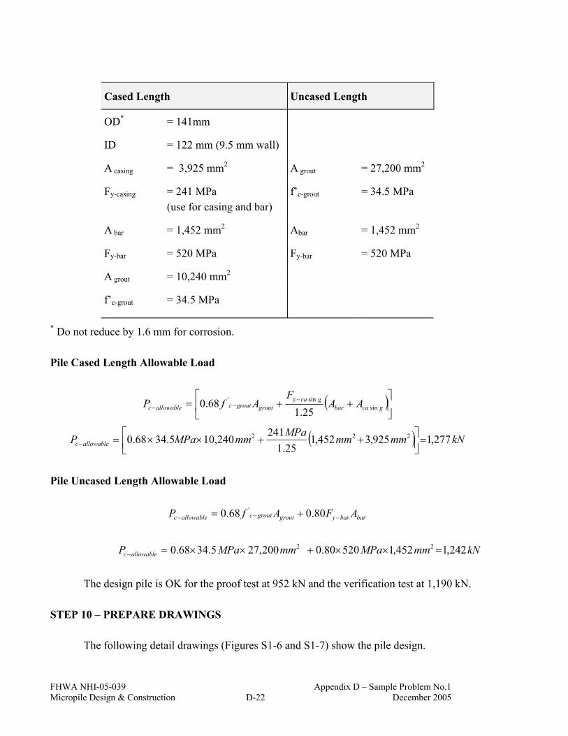
FHWA NHI-05-039 Appendix D – Sample Problem No.1 Micropile Design & Construction D-22 December 2005
Cased Length Uncased Length
OD* = 141mm
ID = 122 mm (9.5 mm wall)
A casing = 3,925 mm2 A grout = 27,200 mm2
Fy-casing = 241 MPa (use for casing and bar)
f’c-grout = 34.5 MPa
A bar = 1,452 mm2 Abar = 1,452 mm2
Fy-bar = 520 MPa Fy-bar = 520 MPa
A grout = 10,240 mm2
f’c-grout = 34.5 MPa
* Do not reduce by 1.6 mm for corrosion.
Pile Cased Length Allowable Load
( )
++= −
−− gcabargcay
groutgroutcallowablec AAF
AfP sinsin'
25.168.0
( ) kNmmmmMPammMPaP allowablec 277,1925,3452,125.1
241240,105.3468.0 222 =
++××=−
Pile Uncased Length Allowable Load
barbarygroutgroutcallowablec AFAfP −−− += 80.068.0 '
kNmmMPammMPaP allowablec 242,1452,152080.0200,275.3468.0 22 =××+××=−
The design pile is OK for the proof test at 952 kN and the verification test at 1,190 kN.
STEP 10 – PREPARE DRAWINGS
The following detail drawings (Figures S1-6 and S1-7) show the pile design.

FHWA NHI-05-039 Appendix D – Sample Problem No.1 Micropile Design & Construction D-23 December 2005
Figure S1-6. Page 1 of Sample Problem No.1 – Working Drawing Submittal

FHWA NHI-05-039 Appendix D – Sample Problem No.1 Micropile Design & Construction D-24 December 2005
Figure S1-7. Page 2 of Sample Problem No. 1 – Working Drawing Submittal

FHWA NHI-05-039 Appendix E – Sample Problem No.2 Micropile Design & Construction E-1 December 2005
SAMPLE PROBLEM NO. 2 – LATERALLY LOADED MICROPILE Micropiles are being considered to support loads for a new multi-story building. The site is underlain by approximately 6 m of undocumented and variable fill overlying partially weathered rock. The soil matrix of the fill is characterized as loose to very dense silty to clayey sand. Approximately 3 m of new fill will be placed over the existing fill to establish foundation grades. The micropile section shown in Figure S2-1 is proposed for the project. The micropiles are required to carry a design axial compression load of 1,423 kN and a design lateral groundline shear load of 44.48 kN. Perform a laterally loaded pile analysis and evaluate:
1. structural capacity of the cased length of the micropile 2. reduced section modulus of the casing joint and proposed bending moment
limit at the casing joints Micropile Section Properties
1. Casing outside diameter (OD) = 0.1969 m. 2. Casing wall thickness (tw) = 0.0151 m. 3. Casing yield strength (Fy) = 552 MPa 4. Grout compressive strength (f’c) = 27.6 MPa
Determine: (1) casing area, Acasing; (2) casing moment of inertia, Icasing; (3) casing section modulus, Scasing; and (4) area of grout, Agrout.
( ) ( )( ) 2222222sin 00863.0)0151.0(21969.01969.0
44mmmIDODA gca =−−=−=
ππ
( ) ( )( ) 4444444sin 00003587.0.)0151.0(21969.0.1969.0
6464mminIDODI gca =−−=−=
ππ
3
4sin
sin 000364.0)2/1969.0(.00003587.0
2/m
mm
ODI
S gcagca ===
2222
sin2 0218.000863.0)1969.0(
4)(
4mmmAODA gcagrout =−=−=
ππ

FHWA NHI-05-039 Appendix E – Sample Problem No.2 Micropile Design & Construction E-2 December 2005
1 in. = 25.4 mm 1 ksi = 6.89 MPa Figure S2-1. Micropile Detail for Sample Problem 2.

FHWA NHI-05-039 Appendix E – Sample Problem No.2 Micropile Design & Construction E-3 December 2005
Laterally Loaded Pile Analysis The computer program LPILE is used to evaluate the maximum bending moment in the cased length of the micropile. For the purposes of this example, both 50% fixity and fixed head (100% fixity) conditions are analyzed. The micropile cap will be embedded 0.91 m below the ground surface. For the analysis, a 0.305-m embedment depth was conservatively assumed. For the analysis, a 12.2-m length of the micropile was modeled. Default LPILE p-y curves for sand above the water table were used to model the soil profile. The upper 3.35 m of the profile was modeled with a soil friction angle of 32 degrees and the remaining portion of the profile (representing the existing fill layer) was modeled with a soil friction angle of 30 degrees. Other soil parameters are provided in the LPILE output file. LPILE Analysis Results The results of the LPILE analysis are provided below and the bending moment diagram and lateral deflection profile are provided in Figures S2-2 and S2-3.
Axial Load (kN)
Fixity Condition
Pile Head Deflection
(mm)
Maximum Shear Load
(kN)
Maximum Bending Moment (kN-m)
1,423 100% 3.3 44.48 -37.3
1,423 50% 8.4 44.48 27.2 Structural Capacity Evaluation (Eq. 5-3)
0.11 '
≤
−
+
be
a
b
a
a
FFff
Ff
Where
MPamkN
AP
fgca
ca 89.164
00863.0423,1
2sin
===
MPammkN
SM
fgca
b 47.102000364.0
3.373
sin
max =−
==

FHWA NHI-05-039 Appendix E – Sample Problem No.2 Micropile Design & Construction E-4 December 2005
MPaMPaFFMPaMPaFF
yb
ya
6.303)552(55.055.0
44.259)552(47.047.0
===
===
Assume buckling potential is negligible, F′e >>> fa
Therefore,
OKMPaMPa
MPaMPa 0.197.0
6.30347.102
44.25989.164
<=+
Structural Capacity Evaluation (Eq. 5-6)
0.1max ≤+− allowableallowablec
c
MM
PP
Where
[ ]kNmMPamMPa
AFAfP gcaygroutcallowablec
479,2)00863.0()552(47.0)0218.0()6.27(4.0
47.04.022
sin'
=+=
+×=−
.5.110)000364.0()552(55.055.0 3
sin mkNmMPaSFM gcayallowable −=== Therefore,
OKmkNmkN
kNkN 0.191.0
5.1103.37
479,2423,1
<=−−
+
Section Modulus at the Joint (Eq. 5-26 )
( ) ( )3
4444
intint 000173.0
2/)0151.01969.0(
)1667.0()0151.01969.0((64
2/
))((64
2/m
mm
mmm
tOD
IDtOD
tODI
Sw
w
w
jojo =
−
−−=
−
−−=
−=
ππ
Maximum Bending Moment at the Joint (Eq. 5-27)
mkNMPaMPaMPamF
Ff
Ff
SM be
a
a
ajojo −=×
−×=
−×
−×= 2.196.303
44.25989.1641000173.011 3
'intint)(max
Using the reduced section modulus at a joint indicates that the combined stress criterion can only be satisfied at the location of a threaded connection (i.e., joint) if the maximum

FHWA NHI-05-039 Appendix E – Sample Problem No.2 Micropile Design & Construction E-5 December 2005
bending moment is 19.2 kN-m or less. This result indicates that threaded connections should not be placed from the bottom of the pile cap to approximately 0.5 m below the ground surface where the micropile-footing connection achieves 100% fixity. For the 50% fixity condition, positive bending moments greater than 19.2 kN-m are computed between a depth of approximately 0.75 to 2.1 m.
Alternatively, if the maximum bending moment needs to be resisted over these depths, the following options could be considered: (1) use a larger casing (with a larger cross sectional area of steel) over this depth range; or (2) place an additional steel casing at least over this length. On projects where a second casing is used, the design should require that joints from the two casings be staggered by at least 1 m.
For the 50% fixity case, a 3-m long casing could be used at the ground surface so that the first threaded connection would be located in an area where acceptable bending resistance could be developed.
0
1
2
3
4
5
6
-40 -20 0 20 40 60Bending Moment (kN-m)
Dep
th (m
)
Fixed Head
50% Fixity
Free Head
Figure S2-2. Bending Moment Diagram for Sample Problem No. 2.
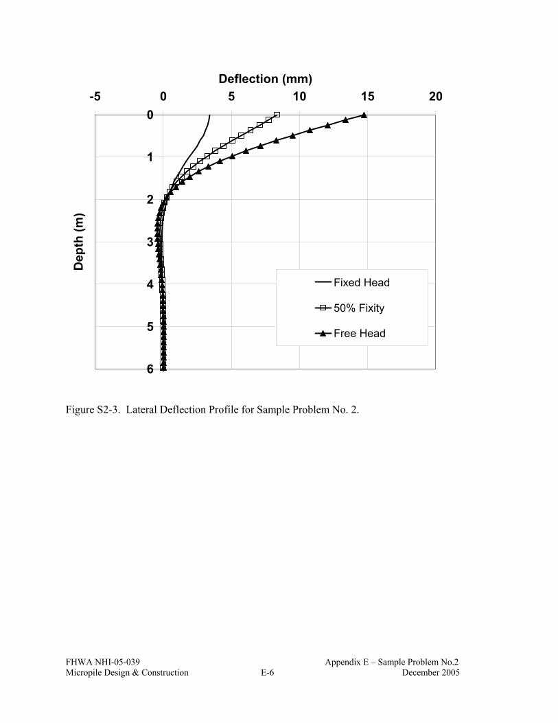
FHWA NHI-05-039 Appendix E – Sample Problem No.2 Micropile Design & Construction E-6 December 2005
0
1
2
3
4
5
6
-5 0 5 10 15 20Deflection (mm)
Dep
th (m
)
Fixed Head
50% Fixity
Free Head
Figure S2-3. Lateral Deflection Profile for Sample Problem No. 2.

FHWA NHI-05-039 Appendix E – Sample Problem No.2 Micropile Design & Construction E-7 December 2005
LPILE ANALYSIS RESULTS
FOR
SAMPLE PROBLEM 2

FHWA NHI-05-039 Appendix E – Sample Problem No.2 Micropile Design & Construction E-8 December 2005
============================================================================== LPILE Plus for Windows, Version 4.0 (4.0.8) Analysis of Individual Piles and Drilled Shafts Subjected to Lateral Loading Using the p-y Method (c) Copyright ENSOFT, Inc., 1985-2003 All Rights Reserved ============================================================================== This program is licensed to: Paul Sabatini GeoSyntec Path to file locations: G:\CWP\CHE8123 - NHI Micropiles\400 - Technical\402 - Revised Manual\Draft 100% Manual\Ch. 5\LPILE Analysis\ Name of input data file: 004SI.lpd Name of output file: 004SI.lpo Name of plot output file: 004SI.lpp Name of runtime file: 004SI.lpr ------------------------------------------------------------------------------ Time and Date of Analysis ------------------------------------------------------------------------------ Date: May 24, 2005 Time: 16:51:45 ------------------------------------------------------------------------------ Problem Title ------------------------------------------------------------------------------ Micropile Manual - Sand Profile ------------------------------------------------------------------------------ Program Options ------------------------------------------------------------------------------ Units Used in Computations - SI Units, meters, kilopascals Basic Program Options: Analysis Type 3: - Computation of Nonlinear Bending Stiffness and Ultimate Bending Moment Capacity with Pile Response Computed Using Nonlinear EI Computation Options: - Only internally-generated p-y curves used in analysis - Analysis does not use p-y multipliers (individual pile or shaft action only) - Analysis assumes no shear resistance at pile tip - Analysis includes automatic computation of pile-top deflection vs. pile embedment length - No computation of foundation stiffness matrix elements - Output pile response for full length of pile - Analysis assumes no soil movements acting on pile - Additional p-y curves computed at specified depths Solution Control Parameters: - Number of pile increments = 100 - Maximum number of iterations allowed = 100 - Deflection tolerance for convergence = 2.5400E-07 m - Maximum allowable deflection = 2.5400E+00 m

FHWA NHI-05-039 Appendix E – Sample Problem No.2 Micropile Design & Construction E-9 December 2005
Printing Options: - Values of pile-head deflection, bending moment, shear force, and soil reaction are printed for full length of pile. - Printing Increment (spacing of output points) = 1 ------------------------------------------------------------------------------ Pile Structural Properties and Geometry ------------------------------------------------------------------------------ Pile Length = 12.19 m Depth of ground surface below top of pile = -.30 m Slope angle of ground surface = .00 deg. Structural properties of pile defined using 2 points Point Depth Pile Moment of Pile Modulus of X Diameter Inertia Area Elasticity m m m**4 Sq. m kN/Sq. m ----- --------- ----------- ---------- ---------- ----------- 1 0.0000 .19685000 3.58667E-05 .008626 199947980.000 2 14.5000 .19685000 3.58667E-05 .008626 199947980.000 Please note that because this analysis makes computations of ultimate moment capacity and pile response using nonlinear bending stiffness that the above values of moment of inertia and modulus of are not used for any computations other than total stress due to combined axial loading and bending. ------------------------------------------------------------------------------ Soil and Rock Layering Information ------------------------------------------------------------------------------ The soil profile is modelled using 2 layers Layer 1 is sand, p-y criteria by Reese et al., 1974 Distance from top of pile to top of layer = -.305 m Distance from top of pile to bottom of layer = 3.048 m p-y subgrade modulus k for top of soil layer = 24430.244 kN/ m**3 p-y subgrade modulus k for bottom of layer = 24430.244 kN/ m**3 Layer 2 is sand, p-y criteria by Reese et al., 1974 Distance from top of pile to top of layer = 3.048 m Distance from top of pile to bottom of layer = 12.192 m p-y subgrade modulus k for top of soil layer = 16286.830 kN/ m**3 p-y subgrade modulus k for bottom of layer = 16286.830 kN/ m**3 (Depth of lowest layer extends .00 m below pile tip) ------------------------------------------------------------------------------ Effective Unit Weight of Soil vs. Depth ------------------------------------------------------------------------------ Distribution of effective unit weight of soil with depth is defined using 4 points Point Depth X Eff. Unit Weight No. m kN/ m**3 ----- ---------- ---------------- 1 -.30 18.83843 2 3.05 18.83843 3 3.05 17.64407 4 12.19 17.64407

FHWA NHI-05-039 Appendix E – Sample Problem No.2 Micropile Design & Construction E-10 December 2005
------------------------------------------------------------------------------ Shear Strength of Soils ------------------------------------------------------------------------------ Distribution of shear strength parameters with depth defined using 4 points Point Depth X Cohesion c Angle of Friction E50 or RQD No. m kN/ m**2 Deg. k_rm % ----- -------- ---------- ------------------ ------ ------ 1 -.305 .00000 32.00 ------ ------ 2 3.048 .00000 32.00 ------ ------ 3 3.048 .00000 30.00 ------ ------ 4 12.192 .00000 30.00 ------ ------ Notes: (1) Cohesion = uniaxial compressive strength for rock materials. (2) Values of E50 are reported for clay strata. (3) Default values will be generated for E50 when input values are 0. (4) RQD and k_rm are reported only for weak rock strata. ------------------------------------------------------------------------------ Loading Type ------------------------------------------------------------------------------ Static loading criteria was used for computation of p-y curves ------------------------------------------------------------------------------ Pile-head Loading and Pile-head Fixity Conditions ------------------------------------------------------------------------------ Number of loads specified = 5 Load Case Number 1 Pile-head boundary conditions are Shear and Slope (BC Type 2) Shear force at pile head = 44.482 kN Slope at pile head = .000 m/ m Axial load at pile head = 1423.431 kN (Zero slope for this load indicates fixed-head condition) Load Case Number 2 Pile-head boundary conditions are Shear and Moment (BC Type 1) Shear force at pile head = 44.482 kN Bending moment at pile head = .000 m- kN Axial load at pile head = 1423.431 kN (Zero moment at pile head for this load indicates a free-head condition) Load Case Number 3 Pile-head boundary conditions are Shear and Rotational Stiffness (BC Type 3) Shear force at pile head = 44.482 kN Rotational stiffness = 88964.449 m- kN Axial load at pile head = 1423.431 kN Load Case Number 4 Pile-head boundary conditions are Shear and Rotational Stiffness (BC Type 3) Shear force at pile head = 44.482 kN Rotational stiffness = 889644.490 m- kN Axial load at pile head = 1423.431 kN

FHWA NHI-05-039 Appendix E – Sample Problem No.2 Micropile Design & Construction E-11 December 2005
Load Case Number 5 Pile-head boundary conditions are Shear and Moment (BC Type 1) Shear force at pile head = 44.482 kN Bending moment at pile head = -18.642 m- kN Axial load at pile head = 1423.431 kN Non-zero moment at pile head for this load case indicates the pile-head may rotate under the applied pile-head loading, but is not a free-head (zero moment) condition. ------------------------------------------------------------------------------ Output of p-y Curves at Specified Depths ------------------------------------------------------------------------------ p-y curves are generated and printed for verification at 7 depths. Depth Depth Below Pile Head Depth Below Ground Surface No. m m ----- --------------------- -------------------------- 1 .000 .305 2 2.020 2.325 3 4.690 4.995 4 4.710 5.015 5 9.990 10.295 6 10.010 10.315 7 12.192 12.497 Depth of ground surface below top of pile = -.30 m **** WARNING **** An unreasonable input value for yield strength of reinforcing steel has been specified. The input value is either smaller than 262,000 kN/m2 or larger than 551,600 kN/m2. You should check you input for correctness. **** WARNING **** An unreasonable input value for concrete cover thickness has been specified. The input value is either smaller than 0.02 meters or larger than 0.2 meters. You should check your input for correctness. ------------------------------------------------------------------------------ Computations of Ultimate Moment Capacity and Nonlinear Bending Stiffness ------------------------------------------------------------------------------ Pile Description: The sectional shape is a circular shaft with steel casing. Outside Diameter = .1969 m Wall thickness of steel shell = .0151 m Cross-sectional area of shell = .00863 m**2 Moment of inertia of steel shell = 3.58702E-05 m**4 Material Properties: Compressive Strength of Concrete = 27579.034 kN/ m**2 Yield Stress of Reinforcement = 27579. kN/ m**2 Steel shell or core yield stress = 551581. kN/ m**2 Modulus of Elasticity of Reinforcement = 199948000. kN/ m**2 Cover Thickness (edge to bar center) = .000 m

FHWA NHI-05-039 Appendix E – Sample Problem No.2 Micropile Design & Construction E-12 December 2005
Number of Reinforcing Bars = 1 Area of Single Bar = .00000 m**2 Number of Rows of Reinforcing Bars = 1 Ultimate Axial Squash Load Capacity = 5270.58 kN Distribution and Area of Steel Reinforcement Row Area of Distance to Number Reinforcement Centroidal Axis m**2 m ------ ------------- --------------- 1 .000000 .0000 Axial Thrust Force = .00 kN Bending Bending Bending Maximum Neutral Axis Moment Stiffness Curvature Strain Position kN-m kN-m2 rad/m m/m m ------------- ------------- ------------- ------------- ------------- 1.61543650 8206.417 .00019685 .00001640 .09842200 2.90699392 8204.183 .00035433 .00002952 .09842200 4.19784752 8201.948 .00051181 .00004264 .09842200 5.48799731 8199.714 .00066929 .00005576 .09842200 6.77744329 8197.479 .00082677 .00006888 .09842200 8.06618545 8195.244 .00098425 .00008200 .09842200 9.35422380 8193.010 .00114173 .00009512 .09842200 10.642 8190.775 .00129921 .00010824 .09842200 10.924 7499.209 .00145669 .00011327 .09287117 12.105 7499.108 .00161417 .00012553 .09288319 13.286 7499.006 .00177165 .00013780 .09289520 14.466 7498.500 .00192913 .00015006 .09290121 15.646 7498.397 .00208661 .00016234 .09291322 16.827 7498.295 .00224409 .00017462 .09292524 18.007 7498.192 .00240157 .00018690 .09293725 19.187 7497.684 .00255906 .00019917 .09294326 20.367 7497.581 .00271654 .00021146 .09295528 21.548 7497.478 .00287402 .00022375 .09296729 22.728 7497.375 .00303150 .00023605 .09297931 23.907 7496.866 .00318898 .00024833 .09298531 25.088 7496.762 .00334646 .00026064 .09299733 26.268 7496.658 .00350394 .00027294 .09300934 27.448 7496.554 .00366142 .00028526 .09302136 28.628 7496.450 .00381890 .00029757 .09303337 29.807 7495.940 .00397638 .00030986 .09303938 38.654 7494.751 .00515748 .00040234 .09312348 47.499 7493.562 .00633858 .00049501 .09320759 56.340 7492.380 .00751969 .00058788 .09329169 65.179 7491.214 .00870079 .00068095 .09337579 74.016 7490.072 .00988189 .00077422 .09345990 82.855 7489.387 .01106299 .00086775 .09355001 91.693 7488.762 .01224409 .00096149 .09364012 100.537 7488.652 .01342520 .00105553 .09373624 109.382 7488.664 .01460630 .00114980 .09383235 118.136 7482.927 .01578740 .00124306 .09385038 126.884 7477.638 .01696850 .00133646 .09387441 135.737 7478.784 .01814961 .00143145 .09398254 144.598 7480.243 .01933071 .00152669 .09409067 153.504 7483.692 .02051181 .00162256 .09421683 162.450 7488.599 .02169291 .00171886 .09434899 171.554 7499.959 .02287402 .00181643 .09452320 181.768 7556.318 .02405512 .00192092 .09496775 190.497 7548.547 .02523622 .00201690 .09503383 199.203 7540.624 .02641732 .00211304 .09509991 207.887 7532.571 .02759843 .00220867 .09514196 216.202 7512.356 .02877953 .00230320 .09514196 223.884 7472.618 .02996063 .00239574 .09507588 228.487 7337.017 .03114173 .00247204 .09449317 232.667 7198.231 .03232283 .00254929 .09398254 236.784 7067.337 .03350394 .00263238 .09368217

FHWA NHI-05-039 Appendix E – Sample Problem No.2 Micropile Design & Construction E-13 December 2005
240.174 6924.418 .03468504 .00271455 .09337579 243.147 6779.298 .03586614 .00279815 .09312949 245.703 6632.145 .03704724 .00288206 .09290722 247.960 6486.275 .03822835 .00296751 .09273901 250.011 6343.943 .03940945 .00305375 .09260084 251.825 6204.036 .04059055 .00313918 .09245066 253.433 6067.107 .04177165 .00322600 .09234252 254.956 5935.730 .04295276 .00331258 .09223439 256.253 5806.259 .04413386 .00339969 .09214428 257.514 5682.756 .04531496 .00348631 .09204816 258.584 5561.408 .04649606 .00357383 .09197607 259.626 5445.491 .04767717 .00366089 .09189798 266.840 5461.521 .04885827 .00374982 .09186193 267.799 5351.757 .05003937 .00384047 .09186193 Ultimate Moment Capacity at a Concrete Strain of 0.003 = 248.732 m- kN Axial Thrust Force = 444.82 kN Bending Bending Bending Maximum Neutral Axis Moment Stiffness Curvature Strain Position kN-m kN-m2 rad/m m/m m ------------- ------------- ------------- ------------- ------------- 1.59641069 8109.766 .00019685 .00021404 1.10243780 2.87353417 8109.752 .00035433 .00022719 .65629032 4.15065210 8109.736 .00051181 .00024034 .48470288 5.42776291 8109.716 .00066929 .00025350 .39387121 6.70486558 8109.694 .00082677 .00026666 .33764809 7.98195810 8109.669 .00098425 .00027983 .29942310 9.25904000 8109.642 .00114173 .00029301 .27174708 10.536 8109.610 .00129921 .00030619 .25078731 11.813 8109.575 .00145669 .00031938 .23436312 13.090 8109.543 .00161417 .00033256 .22114086 14.367 8109.501 .00177165 .00034577 .21027951 15.644 8109.460 .00192913 .00035897 .20119034 16.933 8114.997 .00208661 .00037169 .19324257 18.216 8117.216 .00224409 .00038490 .18662843 19.414 8083.775 .00240157 .00039833 .18097548 20.715 8094.734 .00255906 .00041140 .17587521 21.918 8068.234 .00271654 .00042454 .17139370 23.319 8113.629 .00287402 .00043745 .16732070 24.592 8112.165 .00303150 .00045098 .16387847 25.869 8112.108 .00318898 .00046422 .16068254 26.853 8024.180 .00334646 .00047669 .15755870 27.976 7984.229 .00350394 .00048897 .15466314 29.265 7992.743 .00366142 .00050220 .15227220 30.576 8006.552 .00381890 .00051480 .14991730 31.519 7926.605 .00397638 .00052712 .14767655 40.618 7875.591 .00515748 .00062325 .13595614 49.161 7755.812 .00633858 .00071659 .12816456 58.415 7768.317 .00751969 .00081316 .12325052 66.923 7691.622 .00870079 .00090617 .11926162 75.868 7677.494 .00988189 .00100140 .11645016 85.876 7762.426 .01106299 .00110135 .11466597 92.645 7566.527 .01224409 .00118687 .11204675 103.624 7718.590 .01342520 .00129208 .11135590 110.324 7553.198 .01460630 .00137732 .10940950 118.090 7479.987 .01578740 .00147068 .10826810 130.093 7666.740 .01696850 .00157887 .10815997 136.846 7539.876 .01814961 .00166478 .10683834 144.490 7474.616 .01933071 .00175488 .10589518 152.218 7420.983 .02051181 .00184584 .10510221 160.622 7404.371 .02169291 .00194965 .10498807 169.126 7393.816 .02287402 .00205580 .10498807 182.567 7589.521 .02405512 .00215675 .10477180 188.707 7477.637 .02523622 .00223839 .10381062 196.615 7442.638 .02641732 .00233268 .10341413
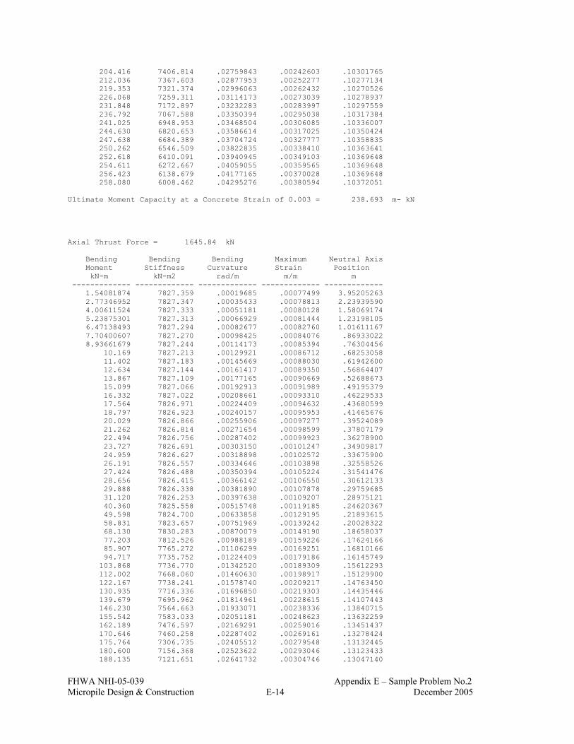
FHWA NHI-05-039 Appendix E – Sample Problem No.2 Micropile Design & Construction E-14 December 2005
204.416 7406.814 .02759843 .00242603 .10301765 212.036 7367.603 .02877953 .00252277 .10277134 219.353 7321.374 .02996063 .00262432 .10270526 226.068 7259.311 .03114173 .00273039 .10278937 231.848 7172.897 .03232283 .00283997 .10297559 236.792 7067.588 .03350394 .00295038 .10317384 241.025 6948.953 .03468504 .00306085 .10336007 244.630 6820.653 .03586614 .00317025 .10350424 247.638 6684.389 .03704724 .00327777 .10358835 250.262 6546.509 .03822835 .00338410 .10363641 252.618 6410.091 .03940945 .00349103 .10369648 254.611 6272.667 .04059055 .00359565 .10369648 256.423 6138.679 .04177165 .00370028 .10369648 258.080 6008.462 .04295276 .00380594 .10372051 Ultimate Moment Capacity at a Concrete Strain of 0.003 = 238.693 m- kN Axial Thrust Force = 1645.84 kN Bending Bending Bending Maximum Neutral Axis Moment Stiffness Curvature Strain Position kN-m kN-m2 rad/m m/m m ------------- ------------- ------------- ------------- ------------- 1.54081874 7827.359 .00019685 .00077499 3.95205263 2.77346952 7827.347 .00035433 .00078813 2.23939590 4.00611524 7827.333 .00051181 .00080128 1.58069174 5.23875301 7827.313 .00066929 .00081444 1.23198105 6.47138493 7827.294 .00082677 .00082760 1.01611167 7.70400607 7827.270 .00098425 .00084076 .86933022 8.93661679 7827.244 .00114173 .00085394 .76304456 10.169 7827.213 .00129921 .00086712 .68253058 11.402 7827.183 .00145669 .00088030 .61942600 12.634 7827.144 .00161417 .00089350 .56864407 13.867 7827.109 .00177165 .00090669 .52688673 15.099 7827.066 .00192913 .00091989 .49195379 16.332 7827.022 .00208661 .00093310 .46229533 17.564 7826.971 .00224409 .00094632 .43680599 18.797 7826.923 .00240157 .00095953 .41465676 20.029 7826.866 .00255906 .00097277 .39524089 21.262 7826.814 .00271654 .00098599 .37807179 22.494 7826.756 .00287402 .00099923 .36278900 23.727 7826.691 .00303150 .00101247 .34909817 24.959 7826.627 .00318898 .00102572 .33675900 26.191 7826.557 .00334646 .00103898 .32558526 27.424 7826.488 .00350394 .00105224 .31541476 28.656 7826.415 .00366142 .00106550 .30612133 29.888 7826.338 .00381890 .00107878 .29759685 31.120 7826.253 .00397638 .00109207 .28975121 40.360 7825.558 .00515748 .00119185 .24620367 49.598 7824.700 .00633858 .00129195 .21893615 58.831 7823.657 .00751969 .00139242 .20028322 68.130 7830.283 .00870079 .00149190 .18658037 77.203 7812.526 .00988189 .00159226 .17624166 85.907 7765.272 .01106299 .00169251 .16810166 94.717 7735.752 .01224409 .00179186 .16145749 103.868 7736.770 .01342520 .00189309 .15612293 112.002 7668.060 .01460630 .00198917 .15129900 122.167 7738.241 .01578740 .00209217 .14763450 130.935 7716.336 .01696850 .00219303 .14435446 139.679 7695.962 .01814961 .00228615 .14107443 146.230 7564.663 .01933071 .00238336 .13840715 155.542 7583.033 .02051181 .00248623 .13632259 162.189 7476.597 .02169291 .00259016 .13451437 170.646 7460.258 .02287402 .00269161 .13278424 175.764 7306.735 .02405512 .00279548 .13132445 180.600 7156.368 .02523622 .00293046 .13123433 188.135 7121.651 .02641732 .00304746 .13047140

FHWA NHI-05-039 Appendix E – Sample Problem No.2 Micropile Design & Construction E-15 December 2005
191.931 6954.404 .02759843 .00316879 .12993073 195.595 6796.323 .02877953 .00329230 .12951021 199.081 6644.766 .02996063 .00341967 .12925190 202.390 6499.001 .03114173 .00355037 .12911973 205.538 6358.908 .03232283 .00368405 .12908970 208.542 6224.398 .03350394 .00382068 .12914977 Ultimate Moment Capacity at a Concrete Strain of 0.003 = 185.078 m- kN p-y Curve in Sand Computed Using Reese Criteria Soil Layer Number = 1 Depth below pile head = .000 m Depth below ground surface = .305 m Equivalent Depth (see note) = .305 m Pile Diameter = .197 m Angle of Friction = 32.000 deg. Avg. Eff. Unit Weight = 18.83843 kN/ m**3 k = 24430.244 kN/m3 A (static) = 1.7329 B (static) = 1.2487 Pst = 7.324 kN/ m Psd = 41.611 kN/ m Ps = 7.324 kN/ m pu = 12.692 kN/ m Cbar = 53.9219 n = 3.2237 m = 864.7227 yk = .0008 m ym = .0033 m yu = .0074 m p-multiplier = 1.00000 y-multiplier = 1.00000 If Psd <= Pst then actual depth is used in place of equivalent depth in computations. y, m p, kN/ m ---------------- ----------------- .0000 .000 .0003 2.036 .0005 4.072 .0008 5.949 .0011 6.504 .0014 6.971 .0016 7.376 .0019 7.737 .0022 8.065 .0025 8.365 .0027 8.643 .0030 8.902 .0033 9.146 .0074 12.692 .2042 12.692 .4011 12.692 .5979 12.692 p-y Curve in Sand Computed Using Reese Criteria Soil Layer Number = 1 Depth below pile head = 2.020 m Depth below ground surface = 2.325 m Equivalent Depth (see note) = 2.325 m Pile Diameter = .197 m

FHWA NHI-05-039 Appendix E – Sample Problem No.2 Micropile Design & Construction E-16 December 2005
Angle of Friction = 32.000 deg. Avg. Eff. Unit Weight = 18.83843 kN/ m**3 k = 24430.244 kN/m3 A (static) = .8800 B (static) = .5000 Pst = 257.686 kN/ m Psd = 317.379 kN/ m Ps = 257.686 kN/ m pu = 226.764 kN/ m Cbar = 4171.9895 n = 1.6447 m = 23877.0680 yk = .0013 m ym = .0033 m yu = .0074 m p-multiplier = 1.00000 y-multiplier = 1.00000 If Psd <= Pst then actual depth is used in place of equivalent depth in computations. y, m p, kN/ m ---------------- ----------------- .0000 .000 .0003 15.528 .0005 31.056 .0008 46.584 .0011 62.112 .0014 75.665 .0016 84.535 .0019 92.841 .0022 100.693 .0025 108.168 .0027 115.324 .0030 122.204 .0033 128.843 .0074 226.764 .2042 226.764 .4011 226.764 .5979 226.764 p-y Curve in Sand Computed Using Reese Criteria Soil Layer Number = 2 Depth below pile head = 4.690 m Depth below ground surface = 4.995 m Equivalent Depth (see note) = 5.449 m Pile Diameter = .197 m Angle of Friction = 30.000 deg. Avg. Eff. Unit Weight = 18.44579 kN/ m**3 k = 16286.830 kN/m3 A (static) = .8800 B (static) = .5000 Pst = 1099.854 kN/ m Psd = 521.333 kN/ m Ps = 521.333 kN/ m pu = 458.773 kN/ m Cbar = 8440.4724 n = 1.6447 m = 48306.3849 yk = .0025 m ym = .0033 m yu = .0074 m p-multiplier = 1.00000 y-multiplier = 1.00000

FHWA NHI-05-039 Appendix E – Sample Problem No.2 Micropile Design & Construction E-17 December 2005
If Psd <= Pst then actual depth is used in place of equivalent depth in computations. y, m p, kN/ m ---------------- ----------------- .0000 .000 .0003 24.265 .0005 48.529 .0008 72.794 .0011 97.058 .0014 121.323 .0016 145.587 .0019 169.852 .0022 194.116 .0025 218.381 .0027 233.315 .0030 247.235 .0033 260.666 .0074 458.773 .2042 458.773 .4011 458.773 .5979 458.773 p-y Curve in Sand Computed Using Reese Criteria Soil Layer Number = 2 Depth below pile head = 4.710 m Depth below ground surface = 5.015 m Equivalent Depth (see note) = 5.469 m Pile Diameter = .197 m Angle of Friction = 30.000 deg. Avg. Eff. Unit Weight = 18.44260 kN/ m**3 k = 16286.830 kN/m3 A (static) = .8800 B (static) = .5000 Pst = 1107.556 kN/ m Psd = 523.330 kN/ m Ps = 523.330 kN/ m pu = 460.530 kN/ m Cbar = 8472.8005 n = 1.6447 m = 48491.4045 yk = .0025 m ym = .0033 m yu = .0074 m p-multiplier = 1.00000 y-multiplier = 1.00000 If Psd <= Pst then actual depth is used in place of equivalent depth in computations. y, m p, kN/ m ---------------- ----------------- .0000 .000 .0003 24.354 .0005 48.707 .0008 73.061 .0011 97.414 .0014 121.768 .0016 146.122 .0019 170.475 .0022 194.829 .0025 219.183 .0027 234.209 .0030 248.182 .0033 261.665 .0074 460.530

FHWA NHI-05-039 Appendix E – Sample Problem No.2 Micropile Design & Construction E-18 December 2005
.2042 460.530 .4011 460.530 .5979 460.530 p-y Curve in Sand Computed Using Reese Criteria Soil Layer Number = 2 Depth below pile head = 9.990 m Depth below ground surface = 10.295 m Equivalent Depth (see note) = 10.749 m Pile Diameter = .197 m Angle of Friction = 30.000 deg. Avg. Eff. Unit Weight = 18.03305 kN/ m**3 k = 16286.830 kN/m3 A (static) = .8800 B (static) = .5000 Pst = 4085.048 kN/ m Psd = 1050.477 kN/ m Ps = 1050.477 kN/ m pu = 924.420 kN/ m Cbar = 17007.4142 n = 1.6447 m = 97336.5779 yk = .0026 m ym = .0033 m yu = .0074 m p-multiplier = 1.00000 y-multiplier = 1.00000 If Psd <= Pst then actual depth is used in place of equivalent depth in computations. y, m p, kN/ m ---------------- ----------------- .0000 .000 .0003 47.865 .0005 95.729 .0008 143.594 .0011 191.459 .0014 239.324 .0016 287.188 .0019 335.053 .0022 382.918 .0025 430.783 .0027 470.126 .0030 498.174 .0033 525.239 .0074 924.420 .2042 924.420 .4011 924.420 .5979 924.420 p-y Curve in Sand Computed Using Reese Criteria Soil Layer Number = 2 Depth below pile head = 10.010 m Depth below ground surface = 10.315 m Equivalent Depth (see note) = 10.769 m Pile Diameter = .197 m Angle of Friction = 30.000 deg. Avg. Eff. Unit Weight = 18.03229 kN/ m**3 k = 16286.830 kN/m3 A (static) = .8800 B (static) = .5000

FHWA NHI-05-039 Appendix E – Sample Problem No.2 Micropile Design & Construction E-19 December 2005
Pst = 4099.902 kN/ m Psd = 1052.474 kN/ m Ps = 1052.474 kN/ m pu = 926.177 kN/ m Cbar = 17039.7421 n = 1.6447 m = 97521.5966 yk = .0026 m ym = .0033 m yu = .0074 m p-multiplier = 1.00000 y-multiplier = 1.00000 If Psd <= Pst then actual depth is used in place of equivalent depth in computations. y, m p, kN/ m ---------------- ----------------- .0000 .000 .0003 47.954 .0005 95.908 .0008 143.861 .0011 191.815 .0014 239.769 .0016 287.723 .0019 335.677 .0022 383.630 .0025 431.584 .0027 471.020 .0030 499.121 .0033 526.237 .0074 926.177 .2042 926.177 .4011 926.177 .5979 926.177 p-y Curve in Sand Computed Using Reese Criteria Soil Layer Number = 2 Depth below pile head = 12.192 m Depth below ground surface = 12.497 m Equivalent Depth (see note) = 12.951 m Pile Diameter = .197 m Angle of Friction = 30.000 deg. Avg. Eff. Unit Weight = 17.96451 kN/ m**3 k = 16286.830 kN/m3 A (static) = .8800 B (static) = .5000 Pst = 5882.580 kN/ m Psd = 1270.322 kN/ m Ps = 1270.322 kN/ m pu = 1117.883 kN/ m Cbar = 20566.7358 n = 1.6447 m = 117707.2342 yk = .0026 m ym = .0033 m yu = .0074 m p-multiplier = 1.00000 y-multiplier = 1.00000 If Psd <= Pst then actual depth is used in place of equivalent depth in computations.
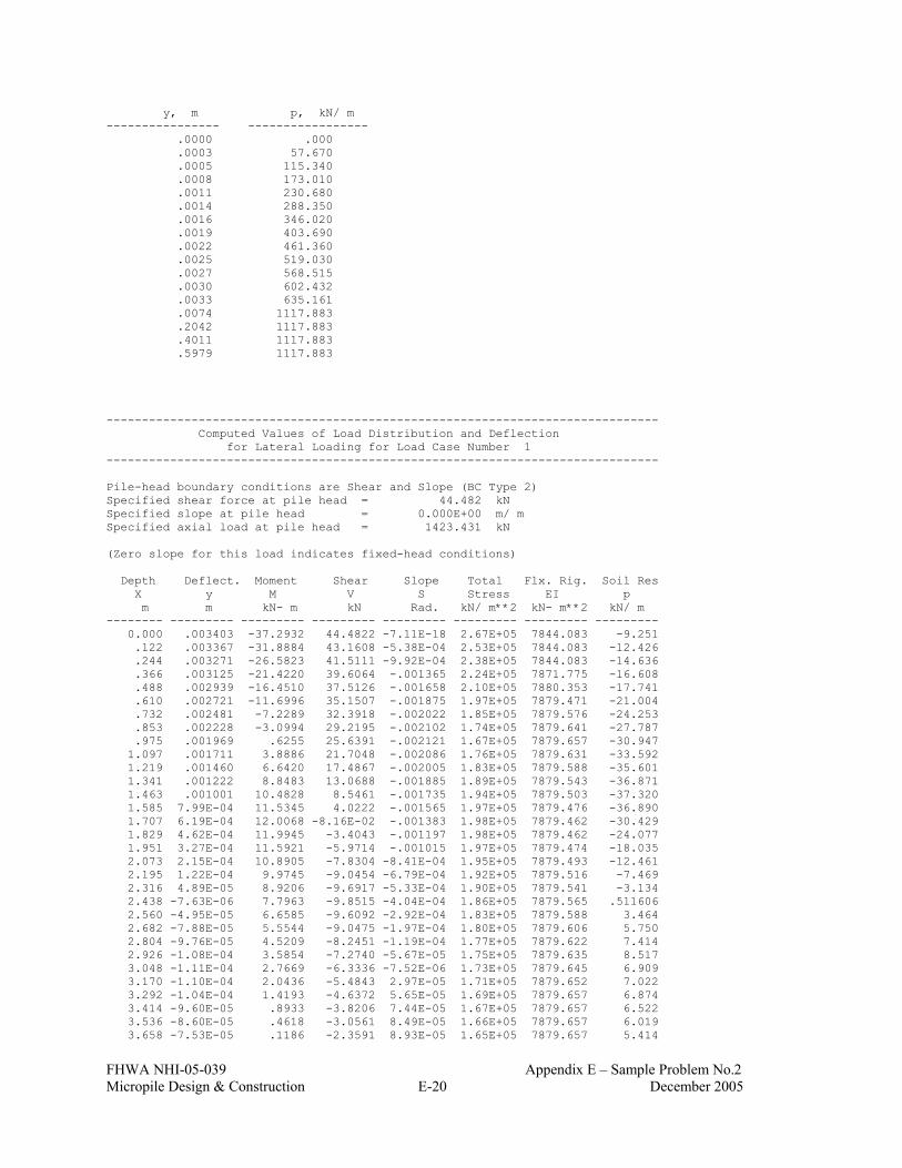
FHWA NHI-05-039 Appendix E – Sample Problem No.2 Micropile Design & Construction E-20 December 2005
y, m p, kN/ m ---------------- ----------------- .0000 .000 .0003 57.670 .0005 115.340 .0008 173.010 .0011 230.680 .0014 288.350 .0016 346.020 .0019 403.690 .0022 461.360 .0025 519.030 .0027 568.515 .0030 602.432 .0033 635.161 .0074 1117.883 .2042 1117.883 .4011 1117.883 .5979 1117.883 ------------------------------------------------------------------------------ Computed Values of Load Distribution and Deflection for Lateral Loading for Load Case Number 1 ------------------------------------------------------------------------------ Pile-head boundary conditions are Shear and Slope (BC Type 2) Specified shear force at pile head = 44.482 kN Specified slope at pile head = 0.000E+00 m/ m Specified axial load at pile head = 1423.431 kN (Zero slope for this load indicates fixed-head conditions) Depth Deflect. Moment Shear Slope Total Flx. Rig. Soil Res X y M V S Stress EI p m m kN- m kN Rad. kN/ m**2 kN- m**2 kN/ m -------- --------- --------- --------- --------- --------- --------- --------- 0.000 .003403 -37.2932 44.4822 -7.11E-18 2.67E+05 7844.083 -9.251 .122 .003367 -31.8884 43.1608 -5.38E-04 2.53E+05 7844.083 -12.426 .244 .003271 -26.5823 41.5111 -9.92E-04 2.38E+05 7844.083 -14.636 .366 .003125 -21.4220 39.6064 -.001365 2.24E+05 7871.775 -16.608 .488 .002939 -16.4510 37.5126 -.001658 2.10E+05 7880.353 -17.741 .610 .002721 -11.6996 35.1507 -.001875 1.97E+05 7879.471 -21.004 .732 .002481 -7.2289 32.3918 -.002022 1.85E+05 7879.576 -24.253 .853 .002228 -3.0994 29.2195 -.002102 1.74E+05 7879.641 -27.787 .975 .001969 .6255 25.6391 -.002121 1.67E+05 7879.657 -30.947 1.097 .001711 3.8886 21.7048 -.002086 1.76E+05 7879.631 -33.592 1.219 .001460 6.6420 17.4867 -.002005 1.83E+05 7879.588 -35.601 1.341 .001222 8.8483 13.0688 -.001885 1.89E+05 7879.543 -36.871 1.463 .001001 10.4828 8.5461 -.001735 1.94E+05 7879.503 -37.320 1.585 7.99E-04 11.5345 4.0222 -.001565 1.97E+05 7879.476 -36.890 1.707 6.19E-04 12.0068 -8.16E-02 -.001383 1.98E+05 7879.462 -30.429 1.829 4.62E-04 11.9945 -3.4043 -.001197 1.98E+05 7879.462 -24.077 1.951 3.27E-04 11.5921 -5.9714 -.001015 1.97E+05 7879.474 -18.035 2.073 2.15E-04 10.8905 -7.8304 -8.41E-04 1.95E+05 7879.493 -12.461 2.195 1.22E-04 9.9745 -9.0454 -6.79E-04 1.92E+05 7879.516 -7.469 2.316 4.89E-05 8.9206 -9.6917 -5.33E-04 1.90E+05 7879.541 -3.134 2.438 -7.63E-06 7.7963 -9.8515 -4.04E-04 1.86E+05 7879.565 .511606 2.560 -4.95E-05 6.6585 -9.6092 -2.92E-04 1.83E+05 7879.588 3.464 2.682 -7.88E-05 5.5544 -9.0475 -1.97E-04 1.80E+05 7879.606 5.750 2.804 -9.76E-05 4.5209 -8.2451 -1.19E-04 1.77E+05 7879.622 7.414 2.926 -1.08E-04 3.5854 -7.2740 -5.67E-05 1.75E+05 7879.635 8.517 3.048 -1.11E-04 2.7669 -6.3336 -7.52E-06 1.73E+05 7879.645 6.909 3.170 -1.10E-04 2.0436 -5.4843 2.97E-05 1.71E+05 7879.652 7.022 3.292 -1.04E-04 1.4193 -4.6372 5.65E-05 1.69E+05 7879.657 6.874 3.414 -9.60E-05 .8933 -3.8206 7.44E-05 1.67E+05 7879.657 6.522 3.536 -8.60E-05 .4618 -3.0561 8.49E-05 1.66E+05 7879.657 6.019 3.658 -7.53E-05 .1186 -2.3591 8.93E-05 1.65E+05 7879.657 5.414

FHWA NHI-05-039 Appendix E – Sample Problem No.2 Micropile Design & Construction E-21 December 2005
3.780 -6.43E-05 -.1444 -1.7395 8.91E-05 1.65E+05 7879.657 4.750 3.901 -5.35E-05 -.3365 -1.2022 8.54E-05 1.66E+05 7879.657 4.063 4.023 -4.34E-05 -.4672 -.7483 7.92E-05 1.66E+05 7879.657 3.383 4.145 -3.42E-05 -.5464 -.3754 7.14E-05 1.67E+05 7879.657 2.733 4.267 -2.60E-05 -.5835 -7.89E-02 6.26E-05 1.67E+05 7879.657 2.131 4.389 -1.89E-05 -.5874 .1478 5.36E-05 1.67E+05 7879.657 1.588 4.511 -1.30E-05 -.5661 .3125 4.46E-05 1.67E+05 7879.657 1.113 4.633 -8.06E-06 -.5267 .4234 3.62E-05 1.66E+05 7879.657 .707571 4.755 -4.14E-06 -.4754 .4893 2.84E-05 1.66E+05 7879.657 .371913 4.877 -1.12E-06 -.4173 .5182 2.15E-05 1.66E+05 7879.657 .103024 4.999 1.11E-06 -.3565 .5181 1.55E-05 1.66E+05 7879.657 -.104035 5.121 2.67E-06 -.2963 .4962 1.05E-05 1.66E+05 7879.657 -.255553 5.243 3.67E-06 -.2392 .4588 6.35E-06 1.66E+05 7879.657 -.358621 5.364 4.22E-06 -.1867 .4113 3.06E-06 1.66E+05 7879.657 -.420666 5.486 4.41E-06 -.1399 .3583 5.33E-07 1.65E+05 7879.657 -.449073 5.608 4.35E-06 -9.95E-02 .3034 -1.32E-06 1.65E+05 7879.657 -.450887 5.730 4.09E-06 -6.55E-02 .2495 -2.60E-06 1.65E+05 7879.657 -.432598 5.852 3.71E-06 -3.77E-02 .1988 -3.39E-06 1.65E+05 7879.657 -.399996 5.974 3.27E-06 -1.58E-02 .1526 -3.81E-06 1.65E+05 7879.657 -.358083 6.096 2.79E-06 7.85E-04 .1118 -3.93E-06 1.65E+05 7879.657 -.311050 6.218 2.31E-06 1.28E-02 7.68E-02 -3.82E-06 1.65E+05 7879.657 -.262281 6.340 1.85E-06 2.08E-02 4.78E-02 -3.56E-06 1.65E+05 7879.657 -.214403 6.462 1.44E-06 2.57E-02 2.44E-02 -3.20E-06 1.65E+05 7879.657 -.169348 6.584 1.07E-06 2.79E-02 6.23E-03 -2.79E-06 1.65E+05 7879.657 -.128437 6.706 7.61E-07 2.82E-02 -7.24E-03 -2.35E-06 1.65E+05 7879.657 -.092472 6.828 5.00E-07 2.70E-02 -1.66E-02 -1.93E-06 1.65E+05 7879.657 -.061825 6.949 2.91E-07 2.48E-02 -2.26E-02 -1.53E-06 1.65E+05 7879.657 -.036527 7.071 1.28E-07 2.20E-02 -2.59E-02 -1.16E-06 1.65E+05 7879.657 -.016356 7.193 6.99E-09 1.89E-02 -2.69E-02 -8.49E-07 1.65E+05 7879.657 -9.05E-04 7.315 -7.87E-08 1.57E-02 -2.63E-02 -5.81E-07 1.65E+05 7879.657 .010349 7.437 -1.35E-07 1.26E-02 -2.46E-02 -3.62E-07 1.65E+05 7879.657 .017992 7.559 -1.67E-07 9.82E-03 -2.21E-02 -1.88E-07 1.65E+05 7879.657 .022627 7.681 -1.81E-07 7.31E-03 -1.92E-02 -5.60E-08 1.65E+05 7879.657 .024844 7.803 -1.81E-07 5.14E-03 -1.62E-02 4.04E-08 1.65E+05 7879.657 .025193 7.925 -1.71E-07 3.34E-03 -1.32E-02 1.06E-07 1.65E+05 7879.657 .024170 8.047 -1.55E-07 1.89E-03 -1.04E-02 1.47E-07 1.65E+05 7879.657 .022203 8.169 -1.35E-07 7.68E-04 -7.81E-03 1.67E-07 1.65E+05 7879.657 .019652 8.291 -1.14E-07 -6.77E-05 -5.58E-03 1.73E-07 1.65E+05 7879.657 .016810 8.412 -9.31E-08 -6.53E-04 -3.71E-03 1.67E-07 1.65E+05 7879.657 .013904 8.534 -7.33E-08 -1.03E-03 -2.19E-03 1.54E-07 1.65E+05 7879.657 .011101 8.656 -5.55E-08 -1.24E-03 -9.90E-04 1.36E-07 1.65E+05 7879.657 .008517 8.778 -4.01E-08 -1.32E-03 -9.12E-05 1.17E-07 1.65E+05 7879.657 .006226 8.900 -2.71E-08 -1.30E-03 5.48E-04 9.63E-08 1.65E+05 7879.657 .004265 9.022 -1.66E-08 -1.22E-03 9.69E-04 7.68E-08 1.65E+05 7879.657 .002644 9.144 -8.38E-09 -1.09E-03 1.21E-03 5.89E-08 1.65E+05 7879.657 .001351 9.266 -2.22E-09 -9.43E-04 1.32E-03 4.32E-08 1.65E+05 7879.657 3.63E-04 9.388 2.15E-09 -7.86E-04 1.32E-03 2.98E-08 1.65E+05 7879.657 -3.55E-04 9.510 5.04E-09 -6.32E-04 1.24E-03 1.88E-08 1.65E+05 7879.657 -8.43E-04 9.632 6.74E-09 -4.89E-04 1.12E-03 1.01E-08 1.65E+05 7879.657 -.001140 9.754 7.51E-09 -3.62E-04 9.76E-04 3.56E-09 1.65E+05 7879.657 -.001286 9.876 7.61E-09 -2.53E-04 8.17E-04 -1.20E-09 1.65E+05 7879.657 -.001317 9.997 7.22E-09 -1.62E-04 6.60E-04 -4.40E-09 1.65E+05 7879.657 -.001265 10.119 6.53E-09 -9.01E-05 5.12E-04 -6.35E-09 1.65E+05 7879.657 -.001157 10.241 5.67E-09 -3.50E-05 3.80E-04 -7.32E-09 1.65E+05 7879.657 -.001016 10.363 4.75E-09 5.09E-06 2.65E-04 -7.55E-09 1.65E+05 7879.657 -8.60E-04 10.485 3.83E-09 3.24E-05 1.70E-04 -7.26E-09 1.65E+05 7879.657 -7.02E-04 10.607 2.98E-09 4.91E-05 9.39E-05 -6.63E-09 1.65E+05 7879.657 -5.51E-04 10.729 2.21E-09 5.75E-05 3.50E-05 -5.81E-09 1.65E+05 7879.657 -4.14E-04 10.851 1.56E-09 5.97E-05 -8.21E-06 -4.90E-09 1.65E+05 7879.657 -2.95E-04 10.973 1.02E-09 5.72E-05 -3.81E-05 -4.00E-09 1.65E+05 7879.657 -1.95E-04 11.095 5.86E-10 5.18E-05 -5.68E-05 -3.15E-09 1.65E+05 7879.657 -1.13E-04 11.217 2.50E-10 4.45E-05 -6.67E-05 -2.41E-09 1.65E+05 7879.657 -4.88E-05 11.339 -1.65E-12 3.64E-05 -6.96E-05 -1.78E-09 1.65E+05 7879.657 3.26E-07 11.460 -1.85E-10 2.81E-05 -6.74E-05 -1.28E-09 1.65E+05 7879.657 3.68E-05 11.582 -3.15E-10 2.04E-05 -6.13E-05 -9.09E-10 1.65E+05 7879.657 6.33E-05 11.704 -4.06E-10 1.35E-05 -5.24E-05 -6.47E-10 1.65E+05 7879.657 8.25E-05 11.826 -4.72E-10 7.82E-06 -4.15E-05 -4.82E-10 1.65E+05 7879.657 9.68E-05 11.948 -5.24E-10 3.56E-06 -2.89E-05 -3.94E-10 1.65E+05 7879.657 1.08E-04 12.070 -5.68E-10 8.97E-07 -1.51E-05 -3.59E-10 1.65E+05 7879.657 1.19E-04 12.192 -6.11E-10 0.0 0.0 -3.52E-10 1.65E+05 7879.657 1.29E-04

FHWA NHI-05-039 Appendix E – Sample Problem No.2 Micropile Design & Construction E-22 December 2005
Please note that because this analysis makes computations of ultimate moment capacity and pile response using nonlinear bending stiffness that the above values of total stress due to combined axial stress and bending may not be representative of actual conditions. Output Verification: Computed forces and moments are within specified convergence limits. Output Summary for Load Case No. 1: Pile-head deflection = .00340258 m Computed slope at pile head = -7.11419E-18 Maximum bending moment = -37.293 kN- m Maximum shear force = 44.482 kN Depth of maximum bending moment = 0.000 m Depth of maximum shear force = 0.000 m Number of iterations = 10 Number of zero deflection points = 5 ------------------------------------------------------------------------------ Computed Values of Load Distribution and Deflection for Lateral Loading for Load Case Number 2 ------------------------------------------------------------------------------ Pile-head boundary conditions are Shear and Moment (BC Type 1) Specified shear force at pile head = 44.482 kN Specified bending moment at pile head = .000 m- kN Specified axial load at pile head = 1423.431 kN (Zero moment for this load indicates free-head conditions) Depth Deflect. Moment Shear Slope Total Flx. Rig. Soil Res X y M V S Stress EI p m m kN- m kN Rad. kN/ m**2 kN- m**2 kN/ m -------- --------- --------- --------- --------- --------- --------- --------- 0.000 .014724 5.52E-12 44.4822 -.010991 1.65E+05 7879.576 -12.692 .122 .013384 7.2364 42.6455 -.010935 1.85E+05 7879.576 -17.437 .244 .012057 14.1941 40.2756 -.010769 2.04E+05 7879.576 -21.439 .366 .010758 20.7951 37.3520 -.010498 2.22E+05 7873.895 -26.520 .488 .009497 26.9459 33.7804 -.010128 2.39E+05 7859.268 -32.069 .610 .008288 32.5476 29.3418 -.009666 2.54E+05 7843.367 -40.743 .732 .007140 37.4558 23.8529 -.009122 2.68E+05 7838.035 -49.298 .853 .006064 41.5301 17.5993 -.008508 2.79E+05 7832.013 -53.287 .975 .005066 44.7001 10.9265 -.007836 2.88E+05 7824.059 -56.174 1.097 .004153 46.9142 3.9683 -.007122 2.94E+05 7818.495 -57.970 1.219 .003329 48.1397 -3.1475 -.006381 2.97E+05 7815.411 -58.759 1.341 .002597 48.3615 -10.2836 -.005628 2.98E+05 7814.853 -58.304 1.463 .001957 47.5856 -17.2581 -.004880 2.96E+05 7816.806 -56.106 1.585 .001407 45.8469 -23.8505 -.004151 2.91E+05 7821.178 -52.038 1.707 9.45E-04 43.2107 -29.8236 -.003457 2.84E+05 7827.798 -45.946 1.829 5.64E-04 39.7748 -34.4167 -.002811 2.74E+05 7835.513 -29.401 1.951 2.59E-04 35.7944 -37.0790 -.002224 2.63E+05 7839.841 -14.272 2.073 2.18E-05 31.5052 -38.0263 -.001701 2.51E+05 7844.499 -1.268 2.195 -1.56E-04 27.1123 -37.5242 -.001245 2.39E+05 7858.247 9.504 2.316 -2.82E-04 22.7876 -35.8446 -8.59E-04 2.28E+05 7879.844 18.049 2.438 -3.65E-04 18.6700 -33.2530 -5.38E-04 2.16E+05 7875.716 24.465 2.560 -4.13E-04 14.8659 -29.9993 -2.78E-04 2.06E+05 7879.373 28.910 2.682 -4.33E-04 11.4516 -26.3110 -7.48E-05 1.96E+05 7879.478 31.594 2.804 -4.31E-04 8.4762 -22.3882 7.93E-05 1.88E+05 7879.551 32.756 2.926 -4.14E-04 5.9649 -18.4013 1.91E-04 1.81E+05 7879.599 32.646 3.048 -3.85E-04 3.9229 -14.9571 2.68E-04 1.76E+05 7879.631 23.853 3.170 -3.48E-04 2.2250 -12.1440 3.15E-04 1.71E+05 7879.650 22.293 3.292 -3.08E-04 .8524 -9.5469 3.39E-04 1.67E+05 7879.657 20.311 3.414 -2.66E-04 -.2206 -7.2079 3.44E-04 1.66E+05 7879.657 18.059 3.536 -2.24E-04 -1.0245 -5.1518 3.34E-04 1.68E+05 7879.657 15.669 3.658 -1.84E-04 -1.5928 -3.3887 3.14E-04 1.69E+05 7879.656 13.253

FHWA NHI-05-039 Appendix E – Sample Problem No.2 Micropile Design & Construction E-23 December 2005
3.780 -1.47E-04 -1.9598 -1.9163 2.86E-04 1.70E+05 7879.653 10.900 3.901 -1.14E-04 -2.1595 -.7226 2.55E-04 1.71E+05 7879.651 8.682 4.023 -8.54E-05 -2.2244 .2121 2.21E-04 1.71E+05 7879.650 6.650 4.145 -6.06E-05 -2.1844 .9125 1.87E-04 1.71E+05 7879.650 4.839 4.267 -3.99E-05 -2.0666 1.4065 1.54E-04 1.71E+05 7879.652 3.265 4.389 -2.31E-05 -1.8948 1.7236 1.23E-04 1.70E+05 7879.653 1.937 4.511 -9.89E-06 -1.6890 1.8935 9.53E-05 1.70E+05 7879.655 .848990 4.633 1.35E-07 -1.4661 1.9445 7.09E-05 1.69E+05 7879.657 -.011839 4.755 7.39E-06 -1.2395 1.9033 5.00E-05 1.68E+05 7879.657 -.664099 4.877 1.23E-05 -1.0194 1.7939 3.25E-05 1.68E+05 7879.657 -1.131 4.999 1.53E-05 -.8133 1.6374 1.83E-05 1.67E+05 7879.657 -1.436 5.121 1.68E-05 -.6264 1.4519 7.17E-06 1.67E+05 7879.657 -1.607 5.243 1.71E-05 -.4618 1.2523 -1.25E-06 1.66E+05 7879.657 -1.668 5.364 1.65E-05 -.3206 1.0505 -7.31E-06 1.66E+05 7879.657 -1.643 5.486 1.53E-05 -.2031 .8556 -1.14E-05 1.66E+05 7879.657 -1.554 5.608 1.37E-05 -.1081 .6742 -1.38E-05 1.65E+05 7879.657 -1.421 5.730 1.19E-05 -3.39E-02 .5107 -1.49E-05 1.65E+05 7879.657 -1.260 5.852 1.01E-05 2.16E-02 .3677 -1.50E-05 1.65E+05 7879.657 -1.085 5.974 8.28E-06 6.09E-02 .2462 -1.43E-05 1.65E+05 7879.657 -.907652 6.096 6.59E-06 8.66E-02 .1460 -1.32E-05 1.65E+05 7879.657 -.735564 6.218 5.06E-06 .1011 6.61E-02 -1.17E-05 1.65E+05 7879.657 -.575335 6.340 3.73E-06 .1068 4.76E-03 -1.01E-05 1.65E+05 7879.657 -.431104 6.462 2.60E-06 .1058 -4.01E-02 -8.47E-06 1.65E+05 7879.657 -.305266 6.584 1.66E-06 10.0E-01 -7.09E-02 -6.88E-06 1.65E+05 7879.657 -.198795 6.706 9.17E-07 9.09E-02 -8.98E-02 -5.41E-06 1.65E+05 7879.657 -.111541 6.828 3.44E-07 7.99E-02 -9.92E-02 -4.08E-06 1.65E+05 7879.657 -.042518 6.949 -7.85E-08 6.81E-02 -.1012 -2.94E-06 1.65E+05 7879.657 .009850 7.071 -3.72E-07 5.63E-02 -9.77E-02 -1.98E-06 1.65E+05 7879.657 .047503 7.193 -5.60E-07 4.50E-02 -9.03E-02 -1.19E-06 1.65E+05 7879.657 .072569 7.315 -6.63E-07 3.47E-02 -8.06E-02 -5.76E-07 1.65E+05 7879.657 .087215 7.437 -7.01E-07 2.56E-02 -6.96E-02 -1.10E-07 1.65E+05 7879.657 .093536 7.559 -6.90E-07 1.78E-02 -5.82E-02 2.25E-07 1.65E+05 7879.657 .093476 7.681 -6.46E-07 1.13E-02 -4.71E-02 4.50E-07 1.65E+05 7879.657 .088769 7.803 -5.80E-07 6.12E-03 -3.67E-02 5.85E-07 1.65E+05 7879.657 .080917 7.925 -5.03E-07 2.13E-03 -2.75E-02 6.48E-07 1.65E+05 7879.657 .071172 8.047 -4.22E-07 -8.01E-04 -1.94E-02 6.59E-07 1.65E+05 7879.657 .060544 8.169 -3.43E-07 -2.83E-03 -1.27E-02 6.31E-07 1.65E+05 7879.657 .049814 8.291 -2.68E-07 -4.12E-03 -7.25E-03 5.77E-07 1.65E+05 7879.657 .039556 8.412 -2.02E-07 -4.80E-03 -3.00E-03 5.08E-07 1.65E+05 7879.657 .030163 8.534 -1.45E-07 -5.02E-03 1.72E-04 4.32E-07 1.65E+05 7879.657 .021877 8.656 -9.66E-08 -4.91E-03 2.41E-03 3.55E-07 1.65E+05 7879.657 .014816 8.778 -5.80E-08 -4.56E-03 3.86E-03 2.82E-07 1.65E+05 7879.657 .009004 8.900 -2.79E-08 -4.07E-03 4.68E-03 2.15E-07 1.65E+05 7879.657 .004391 9.022 -5.53E-09 -3.49E-03 5.00E-03 1.57E-07 1.65E+05 7879.657 8.81E-04 9.144 1.03E-08 -2.90E-03 4.95E-03 1.07E-07 1.65E+05 7879.657 -.001655 9.266 2.06E-08 -2.32E-03 4.65E-03 6.67E-08 1.65E+05 7879.657 -.003360 9.388 2.65E-08 -1.79E-03 4.17E-03 3.48E-08 1.65E+05 7879.657 -.004382 9.510 2.91E-08 -1.32E-03 3.61E-03 1.08E-08 1.65E+05 7879.657 -.004862 9.632 2.91E-08 -9.14E-04 3.01E-03 -6.49E-09 1.65E+05 7879.657 -.004932 9.754 2.75E-08 -5.81E-04 2.43E-03 -1.81E-08 1.65E+05 7879.657 -.004706 9.876 2.47E-08 -3.16E-04 1.88E-03 -2.50E-08 1.65E+05 7879.657 -.004285 9.997 2.14E-08 -1.14E-04 1.39E-03 -2.83E-08 1.65E+05 7879.657 -.003748 10.119 1.78E-08 3.23E-05 9.68E-04 -2.90E-08 1.65E+05 7879.657 -.003159 10.241 1.43E-08 1.32E-04 6.18E-04 -2.77E-08 1.65E+05 7879.657 -.002567 10.363 1.11E-08 1.93E-04 3.40E-04 -2.52E-08 1.65E+05 7879.657 -.002007 10.485 8.19E-09 2.23E-04 1.26E-04 -2.20E-08 1.65E+05 7879.657 -.001500 10.607 5.72E-09 2.31E-04 -3.00E-05 -1.84E-08 1.65E+05 7879.657 -.001059 10.729 3.69E-09 2.22E-04 -1.37E-04 -1.49E-08 1.65E+05 7879.657 -6.90E-04 10.851 2.08E-09 2.03E-04 -2.03E-04 -1.17E-08 1.65E+05 7879.657 -3.93E-04 10.973 8.48E-10 1.77E-04 -2.37E-04 -8.71E-09 1.65E+05 7879.657 -1.62E-04 11.095 -4.72E-11 1.48E-04 -2.46E-04 -6.20E-09 1.65E+05 7879.657 9.11E-06 11.217 -6.63E-10 1.19E-04 -2.37E-04 -4.13E-09 1.65E+05 7879.657 1.29E-04 11.339 -1.05E-09 9.18E-05 -2.17E-04 -2.49E-09 1.65E+05 7879.657 2.08E-04 11.460 -1.27E-09 6.72E-05 -1.89E-04 -1.26E-09 1.65E+05 7879.657 2.53E-04 11.582 -1.36E-09 4.62E-05 -1.57E-04 -3.86E-10 1.65E+05 7879.657 2.74E-04 11.704 -1.37E-09 2.91E-05 -1.23E-04 1.97E-10 1.65E+05 7879.657 2.77E-04 11.826 -1.31E-09 1.61E-05 -8.98E-05 5.47E-10 1.65E+05 7879.657 2.69E-04 11.948 -1.23E-09 7.06E-06 -5.78E-05 7.26E-10 1.65E+05 7879.657 2.55E-04 12.070 -1.14E-09 1.77E-06 -2.78E-05 7.95E-10 1.65E+05 7879.657 2.37E-04 12.192 -1.04E-09 0.0 0.0 8.08E-10 1.65E+05 7879.657 2.19E-04

FHWA NHI-05-039 Appendix E – Sample Problem No.2 Micropile Design & Construction E-24 December 2005
Please note that because this analysis makes computations of ultimate moment capacity and pile response using nonlinear bending stiffness that the above values of total stress due to combined axial stress and bending may not be representative of actual conditions. Output Verification: Computed forces and moments are within specified convergence limits. Output Summary for Load Case No. 2: Pile-head deflection = .01472369 m Computed slope at pile head = -.01099103 Maximum bending moment = 48.361 kN- m Maximum shear force = 44.482 kN Depth of maximum bending moment = 1.34112000 m Depth of maximum shear force = 0.000 m Number of iterations = 16 Number of zero deflection points = 5 ------------------------------------------------------------------------------ Computed Values of Load Distribution and Deflection for Lateral Loading for Load Case Number 3 ------------------------------------------------------------------------------ Pile-head boundary conditions are Shear and Rotational Stiffness (BC Type 3) Specified shear force at pile head = 44.482 kN Specified rotational stiffness = 88964.449 m- kN/rad Specified axial load at pile head = 1423.431 kN Depth Deflect. Moment Shear Slope Total Flx. Rig. Soil Res X y M V S Stress EI p m m kN- m kN Rad. kN/ m**2 kN- m**2 kN/ m -------- --------- --------- --------- --------- --------- --------- --------- 0.000 .003792 -35.7869 44.4822 -4.02E-04 2.63E+05 7855.921 -9.588 .122 .003709 -30.3169 43.1143 -9.15E-04 2.48E+05 7855.921 -12.853 .244 .003569 -24.9563 41.4085 -.001344 2.34E+05 7855.921 -15.128 .366 .003381 -19.7533 39.4373 -.001691 2.19E+05 7875.828 -17.208 .488 .003156 -14.7531 37.2627 -.001958 2.06E+05 7879.377 -18.465 .610 .002904 -9.9877 34.8067 -.002149 1.92E+05 7879.515 -21.824 .732 .002632 -5.5199 31.9438 -.002269 1.80E+05 7879.606 -25.140 .853 .002351 -1.4109 28.6613 -.002323 1.69E+05 7879.657 -28.706 .975 .002066 2.2751 24.9689 -.002316 1.71E+05 7879.649 -31.866 1.097 .001786 5.4813 20.9246 -.002256 1.80E+05 7879.607 -34.478 1.219 .001516 8.1604 16.6026 -.002150 1.87E+05 7879.557 -36.420 1.341 .001261 10.2761 12.0911 -.002008 1.93E+05 7879.508 -37.587 1.463 .001026 11.8056 7.4896 -.001837 1.97E+05 7879.468 -37.898 1.585 8.13E-04 12.7400 2.9059 -.001647 2.00E+05 7879.440 -37.294 1.707 6.25E-04 13.0858 -1.2391 -.001447 2.01E+05 7879.429 -30.701 1.829 4.61E-04 12.9402 -4.5741 -.001246 2.01E+05 7879.434 -24.007 1.951 3.21E-04 12.4029 -7.1154 -.001050 1.99E+05 7879.450 -17.681 2.073 2.05E-04 11.5696 -8.9176 -8.64E-04 1.97E+05 7879.475 -11.882 2.195 1.10E-04 10.5285 -10.0518 -6.93E-04 1.94E+05 7879.502 -6.723 2.316 3.55E-05 9.3592 -10.6001 -5.40E-04 1.91E+05 7879.531 -2.273 2.438 -2.15E-05 8.1310 -10.6509 -4.04E-04 1.87E+05 7879.558 1.439 2.560 -6.31E-05 6.9024 -10.2940 -2.88E-04 1.84E+05 7879.583 4.416 2.682 -9.17E-05 5.7209 -9.6169 -1.90E-04 1.81E+05 7879.603 6.691 2.804 -1.09E-04 4.6235 -8.7021 -1.10E-04 1.78E+05 7879.620 8.316 2.926 -1.19E-04 3.6373 -7.6246 -4.64E-05 1.75E+05 7879.634 9.360 3.048 -1.21E-04 2.7804 -6.5974 3.28E-06 1.73E+05 7879.644 7.491 3.170 -1.18E-04 2.0274 -5.6813 4.05E-05 1.71E+05 7879.652 7.537 3.292 -1.11E-04 1.3810 -4.7757 6.68E-05 1.69E+05 7879.657 7.319 3.414 -1.01E-04 .8397 -3.9090 8.40E-05 1.67E+05 7879.657 6.897 3.536 -9.04E-05 .3987 -3.1029 9.36E-05 1.66E+05 7879.657 6.327 3.658 -7.87E-05 5.06E-02 -2.3724 9.71E-05 1.65E+05 7879.657 5.658

FHWA NHI-05-039 Appendix E – Sample Problem No.2 Micropile Design & Construction E-25 December 2005
3.780 -6.68E-05 -.2135 -1.7265 9.58E-05 1.66E+05 7879.657 4.936 3.901 -5.53E-05 -.4037 -1.1698 9.10E-05 1.66E+05 7879.657 4.197 4.023 -4.46E-05 -.5303 -.7023 8.38E-05 1.66E+05 7879.657 3.472 4.145 -3.49E-05 -.6040 -.3210 7.50E-05 1.67E+05 7879.657 2.784 4.267 -2.63E-05 -.6347 -2.02E-02 6.55E-05 1.67E+05 7879.657 2.151 4.389 -1.89E-05 -.6316 .2075 5.57E-05 1.67E+05 7879.657 1.584 4.511 -1.27E-05 -.6034 .3705 4.61E-05 1.67E+05 7879.657 1.090 4.633 -7.65E-06 -.5573 .4779 3.71E-05 1.67E+05 7879.657 .671482 4.755 -3.64E-06 -.4997 .5388 2.90E-05 1.66E+05 7879.657 .327315 4.877 -5.86E-07 -.4360 .5620 2.17E-05 1.66E+05 7879.657 .053792 4.999 1.65E-06 -.3702 .5558 1.55E-05 1.66E+05 7879.657 -.154750 5.121 3.19E-06 -.3058 .5278 1.02E-05 1.66E+05 7879.657 -.305287 5.243 4.15E-06 -.2451 .4845 5.98E-06 1.66E+05 7879.657 -.405540 5.364 4.65E-06 -.1898 .4315 2.62E-06 1.66E+05 7879.657 -.463495 5.486 4.79E-06 -.1408 .3736 6.34E-08 1.65E+05 7879.657 -.487017 5.608 4.66E-06 -9.87E-02 .3144 -1.79E-06 1.65E+05 7879.657 -.483553 5.730 4.35E-06 -6.35E-02 .2569 -3.04E-06 1.65E+05 7879.657 -.459915 5.852 3.92E-06 -3.50E-02 .2031 -3.81E-06 1.65E+05 7879.657 -.422140 5.974 3.42E-06 -1.27E-02 .1545 -4.18E-06 1.65E+05 7879.657 -.375413 6.096 2.90E-06 4.12E-03 .1118 -4.24E-06 1.65E+05 7879.657 -.324044 6.218 2.39E-06 1.61E-02 7.55E-02 -4.08E-06 1.65E+05 7879.657 -.271489 6.340 1.91E-06 2.40E-02 4.56E-02 -3.78E-06 1.65E+05 7879.657 -.220402 6.462 1.47E-06 2.85E-02 2.16E-02 -3.37E-06 1.65E+05 7879.657 -.172713 6.584 1.08E-06 3.04E-02 3.15E-03 -2.91E-06 1.65E+05 7879.657 -.129714 6.706 7.58E-07 3.03E-02 -1.04E-02 -2.44E-06 1.65E+05 7879.657 -.092161 6.828 4.89E-07 2.87E-02 -1.97E-02 -1.99E-06 1.65E+05 7879.657 -.060368 6.949 2.73E-07 2.62E-02 -2.54E-02 -1.56E-06 1.65E+05 7879.657 -.034304 7.071 1.07E-07 2.30E-02 -2.84E-02 -1.18E-06 1.65E+05 7879.657 -.013682 7.193 -1.52E-08 1.97E-02 -2.91E-02 -8.52E-07 1.65E+05 7879.657 .001968 7.315 -1.01E-07 1.63E-02 -2.82E-02 -5.75E-07 1.65E+05 7879.657 .013226 7.437 -1.55E-07 1.30E-02 -2.61E-02 -3.48E-07 1.65E+05 7879.657 .020730 7.559 -1.85E-07 1.00E-02 -2.33E-02 -1.70E-07 1.65E+05 7879.657 .025129 7.681 -1.97E-07 7.38E-03 -2.01E-02 -3.56E-08 1.65E+05 7879.657 .027051 7.803 -1.94E-07 5.12E-03 -1.68E-02 6.11E-08 1.65E+05 7879.657 .027077 7.925 -1.82E-07 3.26E-03 -1.36E-02 1.26E-07 1.65E+05 7879.657 .025725 8.047 -1.63E-07 1.77E-03 -1.06E-02 1.65E-07 1.65E+05 7879.657 .023443 8.169 -1.42E-07 6.19E-04 -7.91E-03 1.83E-07 1.65E+05 7879.657 .020603 8.291 -1.19E-07 -2.25E-04 -5.58E-03 1.86E-07 1.65E+05 7879.657 .017505 8.412 -9.63E-08 -8.07E-04 -3.64E-03 1.78E-07 1.65E+05 7879.657 .014379 8.534 -7.53E-08 -1.17E-03 -2.07E-03 1.63E-07 1.65E+05 7879.657 .011394 8.656 -5.65E-08 -1.37E-03 -8.46E-04 1.43E-07 1.65E+05 7879.657 .008665 8.778 -4.03E-08 -1.43E-03 6.39E-05 1.22E-07 1.65E+05 7879.657 .006263 8.900 -2.68E-08 -1.40E-03 7.03E-04 9.98E-08 1.65E+05 7879.657 .004221 9.022 -1.60E-08 -1.29E-03 1.12E-03 7.90E-08 1.65E+05 7879.657 .002545 9.144 -7.56E-09 -1.15E-03 1.34E-03 6.01E-08 1.65E+05 7879.657 .001219 9.266 -1.31E-09 -9.86E-04 1.43E-03 4.36E-08 1.65E+05 7879.657 2.14E-04 9.388 3.07E-09 -8.17E-04 1.41E-03 2.97E-08 1.65E+05 7879.657 -5.08E-04 9.510 5.92E-09 -6.52E-04 1.32E-03 1.83E-08 1.65E+05 7879.657 -9.90E-04 9.632 7.53E-09 -5.00E-04 1.18E-03 9.38E-09 1.65E+05 7879.657 -.001275 9.754 8.21E-09 -3.66E-04 1.02E-03 2.67E-09 1.65E+05 7879.657 -.001405 9.876 8.19E-09 -2.52E-04 8.49E-04 -2.11E-09 1.65E+05 7879.657 -.001418 9.997 7.69E-09 -1.58E-04 6.81E-04 -5.29E-09 1.65E+05 7879.657 -.001348 10.119 6.90E-09 -8.43E-05 5.24E-04 -7.16E-09 1.65E+05 7879.657 -.001222 10.241 5.95E-09 -2.81E-05 3.85E-04 -8.03E-09 1.65E+05 7879.657 -.001065 10.363 4.94E-09 1.23E-05 2.65E-04 -8.15E-09 1.65E+05 7879.657 -8.95E-04 10.485 3.96E-09 3.94E-05 1.67E-04 -7.75E-09 1.65E+05 7879.657 -7.25E-04 10.607 3.05E-09 5.56E-05 8.80E-05 -7.02E-09 1.65E+05 7879.657 -5.64E-04 10.729 2.25E-09 6.33E-05 2.79E-05 -6.10E-09 1.65E+05 7879.657 -4.20E-04 10.851 1.56E-09 6.46E-05 -1.57E-05 -5.11E-09 1.65E+05 7879.657 -2.95E-04 10.973 1.00E-09 6.13E-05 -4.54E-05 -4.13E-09 1.65E+05 7879.657 -1.91E-04 11.095 5.54E-10 5.49E-05 -6.35E-05 -3.24E-09 1.65E+05 7879.657 -1.07E-04 11.217 2.12E-10 4.69E-05 -7.26E-05 -2.45E-09 1.65E+05 7879.657 -4.13E-05 11.339 -4.26E-11 3.81E-05 -7.46E-05 -1.79E-09 1.65E+05 7879.657 8.40E-06 11.460 -2.25E-10 2.93E-05 -7.13E-05 -1.27E-09 1.65E+05 7879.657 4.48E-05 11.582 -3.52E-10 2.11E-05 -6.43E-05 -8.78E-10 1.65E+05 7879.657 7.07E-05 11.704 -4.39E-10 1.40E-05 -5.45E-05 -6.06E-10 1.65E+05 7879.657 8.91E-05 11.826 -5.00E-10 8.05E-06 -4.29E-05 -4.36E-10 1.65E+05 7879.657 1.02E-04 11.948 -5.45E-10 3.65E-06 -2.97E-05 -3.46E-10 1.65E+05 7879.657 1.13E-04 12.070 -5.84E-10 9.21E-07 -1.54E-05 -3.10E-10 1.65E+05 7879.657 1.22E-04 12.192 -6.21E-10 0.0 0.0 -3.03E-10 1.65E+05 7879.657 1.31E-04

FHWA NHI-05-039 Appendix E – Sample Problem No.2 Micropile Design & Construction E-26 December 2005
Please note that because this analysis makes computations of ultimate moment capacity and pile response using nonlinear bending stiffness that the above values of total stress due to combined axial stress and bending may not be representative of actual conditions. Output Verification: Computed forces and moments are within specified convergence limits. Output Summary for Load Case No. 3: Pile-head deflection = .00379184 m Computed slope at pile head = -.00040226 Maximum bending moment = -35.787 kN- m Maximum shear force = 44.482 kN Depth of maximum bending moment = 0.000 m Depth of maximum shear force = 0.000 m Number of iterations = 10 Number of zero deflection points = 5 ------------------------------------------------------------------------------ Computed Values of Load Distribution and Deflection for Lateral Loading for Load Case Number 4 ------------------------------------------------------------------------------ Pile-head boundary conditions are Shear and Rotational Stiffness (BC Type 3) Specified shear force at pile head = 44.482 kN Specified rotational stiffness = 889644.490 m- kN/rad Specified axial load at pile head = 1423.431 kN Depth Deflect. Moment Shear Slope Total Flx. Rig. Soil Res X y M V S Stress EI p m m kN- m kN Rad. kN/ m**2 kN- m**2 kN/ m -------- --------- --------- --------- --------- --------- --------- --------- 0.000 .003443 -37.1359 44.4822 -4.17E-05 2.67E+05 7844.262 -9.286 .122 .003403 -31.7243 43.1559 -5.77E-04 2.52E+05 7844.262 -12.470 .244 .003302 -26.4125 41.5004 -.001029 2.38E+05 7844.262 -14.687 .366 .003152 -21.2478 39.5888 -.001398 2.23E+05 7872.070 -16.671 .488 .002961 -16.2738 37.4864 -.001689 2.10E+05 7880.216 -17.817 .610 .002740 -11.5209 35.1146 -.001904 1.97E+05 7879.476 -21.090 .732 .002497 -7.0506 32.3448 -.002048 1.84E+05 7879.580 -24.346 .853 .002241 -2.9233 29.1609 -.002125 1.73E+05 7879.643 -27.883 .975 .001979 .7975 25.5688 -.002141 1.67E+05 7879.657 -31.043 1.097 .001719 4.0546 21.6230 -.002104 1.76E+05 7879.629 -33.685 1.219 .001466 6.8002 17.3941 -.002020 1.84E+05 7879.585 -35.687 1.341 .001226 8.9970 12.9665 -.001897 1.90E+05 7879.540 -36.945 1.463 .001003 10.6205 8.4356 -.001746 1.94E+05 7879.499 -37.380 1.585 8.01E-04 11.6599 3.9055 -.001573 1.97E+05 7879.472 -36.932 1.707 6.20E-04 12.1190 -.2025 -.001389 1.98E+05 7879.458 -30.457 1.829 4.62E-04 12.0928 -3.5263 -.001202 1.98E+05 7879.459 -24.069 1.951 3.27E-04 11.6763 -6.0907 -.001018 1.97E+05 7879.472 -17.997 2.073 2.13E-04 10.9610 -7.9436 -8.43E-04 1.95E+05 7879.491 -12.400 2.195 1.21E-04 10.0319 -9.1501 -6.81E-04 1.93E+05 7879.514 -7.391 2.316 4.75E-05 8.9661 -9.7862 -5.34E-04 1.90E+05 7879.540 -3.043 2.438 -9.08E-06 7.8309 -9.9346 -4.04E-04 1.87E+05 7879.565 .608417 2.560 -5.09E-05 6.6837 -9.6803 -2.91E-04 1.83E+05 7879.587 3.563 2.682 -8.01E-05 5.5716 -9.1066 -1.97E-04 1.80E+05 7879.605 5.848 2.804 -9.88E-05 4.5314 -8.2925 -1.18E-04 1.77E+05 7879.622 7.508 2.926 -1.09E-04 3.5907 -7.3103 -5.56E-05 1.75E+05 7879.635 8.604 3.048 -1.12E-04 2.7682 -6.3609 -6.39E-06 1.73E+05 7879.645 6.970 3.170 -1.11E-04 2.0419 -5.5047 3.08E-05 1.71E+05 7879.652 7.076 3.292 -1.05E-04 1.4152 -4.6515 5.76E-05 1.69E+05 7879.657 6.920 3.414 -9.65E-05 .8877 -3.8297 7.54E-05 1.67E+05 7879.657 6.561 3.536 -8.65E-05 .4552 -3.0609 8.58E-05 1.66E+05 7879.657 6.051 3.658 -7.56E-05 .1115 -2.3604 9.02E-05 1.65E+05 7879.657 5.440

FHWA NHI-05-039 Appendix E – Sample Problem No.2 Micropile Design & Construction E-27 December 2005
3.780 -6.45E-05 -.1516 -1.7381 8.98E-05 1.65E+05 7879.657 4.770 3.901 -5.37E-05 -.3435 -1.1988 8.60E-05 1.66E+05 7879.657 4.077 4.023 -4.35E-05 -.4738 -.7434 7.97E-05 1.66E+05 7879.657 3.392 4.145 -3.43E-05 -.5524 -.3697 7.18E-05 1.67E+05 7879.657 2.738 4.267 -2.61E-05 -.5888 -7.28E-02 6.29E-05 1.67E+05 7879.657 2.133 4.389 -1.89E-05 -.5920 .1540 5.38E-05 1.67E+05 7879.657 1.588 4.511 -1.29E-05 -.5700 .3185 4.48E-05 1.67E+05 7879.657 1.111 4.633 -8.01E-06 -.5299 .4291 3.63E-05 1.66E+05 7879.657 .703775 4.755 -4.09E-06 -.4779 .4944 2.85E-05 1.66E+05 7879.657 .367242 4.877 -1.07E-06 -.4192 .5228 2.16E-05 1.66E+05 7879.657 .097879 4.999 1.17E-06 -.3579 .5221 1.55E-05 1.66E+05 7879.657 -.109326 5.121 2.72E-06 -.2973 .4995 1.05E-05 1.66E+05 7879.657 -.260736 5.243 3.72E-06 -.2398 .4614 6.31E-06 1.66E+05 7879.657 -.363506 5.364 4.26E-06 -.1870 .4134 3.01E-06 1.66E+05 7879.657 -.425121 5.486 4.45E-06 -.1400 .3598 4.84E-07 1.65E+05 7879.657 -.453017 5.608 4.38E-06 -9.94E-02 .3045 -1.37E-06 1.65E+05 7879.657 -.454280 5.730 4.12E-06 -6.53E-02 .2503 -2.64E-06 1.65E+05 7879.657 -.435433 5.852 3.74E-06 -3.75E-02 .1992 -3.44E-06 1.65E+05 7879.657 -.402292 5.974 3.28E-06 -1.55E-02 .1528 -3.85E-06 1.65E+05 7879.657 -.359878 6.096 2.80E-06 1.13E-03 .1118 -3.96E-06 1.65E+05 7879.657 -.312394 6.218 2.32E-06 1.31E-02 7.67E-02 -3.85E-06 1.65E+05 7879.657 -.263232 6.340 1.86E-06 2.12E-02 4.75E-02 -3.58E-06 1.65E+05 7879.657 -.215021 6.462 1.44E-06 2.60E-02 2.41E-02 -3.22E-06 1.65E+05 7879.657 -.169692 6.584 1.08E-06 2.82E-02 5.91E-03 -2.80E-06 1.65E+05 7879.657 -.128565 6.706 7.60E-07 2.84E-02 -7.57E-03 -2.36E-06 1.65E+05 7879.657 -.092436 6.828 4.99E-07 2.71E-02 -1.70E-02 -1.93E-06 1.65E+05 7879.657 -.061670 6.949 2.89E-07 2.49E-02 -2.29E-02 -1.53E-06 1.65E+05 7879.657 -.036294 7.071 1.26E-07 2.21E-02 -2.61E-02 -1.17E-06 1.65E+05 7879.657 -.016076 7.193 4.67E-09 1.89E-02 -2.71E-02 -8.49E-07 1.65E+05 7879.657 -6.05E-04 7.315 -8.10E-08 1.58E-02 -2.65E-02 -5.81E-07 1.65E+05 7879.657 .010649 7.437 -1.37E-07 1.27E-02 -2.48E-02 -3.61E-07 1.65E+05 7879.657 .018277 7.559 -1.69E-07 9.84E-03 -2.23E-02 -1.87E-07 1.65E+05 7879.657 .022887 7.681 -1.82E-07 7.31E-03 -1.93E-02 -5.38E-08 1.65E+05 7879.657 .025073 7.803 -1.82E-07 5.14E-03 -1.63E-02 4.25E-08 1.65E+05 7879.657 .025389 7.925 -1.72E-07 3.34E-03 -1.32E-02 1.08E-07 1.65E+05 7879.657 .024331 8.047 -1.56E-07 1.88E-03 -1.04E-02 1.48E-07 1.65E+05 7879.657 .022331 8.169 -1.36E-07 7.52E-04 -7.82E-03 1.69E-07 1.65E+05 7879.657 .019751 8.291 -1.15E-07 -8.41E-05 -5.58E-03 1.74E-07 1.65E+05 7879.657 .016882 8.412 -9.34E-08 -6.69E-04 -3.70E-03 1.68E-07 1.65E+05 7879.657 .013953 8.534 -7.35E-08 -1.05E-03 -2.17E-03 1.55E-07 1.65E+05 7879.657 .011131 8.656 -5.56E-08 -1.25E-03 -9.75E-04 1.37E-07 1.65E+05 7879.657 .008532 8.778 -4.01E-08 -1.33E-03 -7.50E-05 1.17E-07 1.65E+05 7879.657 .006229 8.900 -2.71E-08 -1.31E-03 5.64E-04 9.67E-08 1.65E+05 7879.657 .004260 9.022 -1.65E-08 -1.23E-03 9.85E-04 7.70E-08 1.65E+05 7879.657 .002633 9.144 -8.29E-09 -1.10E-03 1.23E-03 5.91E-08 1.65E+05 7879.657 .001338 9.266 -2.13E-09 -9.48E-04 1.33E-03 4.32E-08 1.65E+05 7879.657 3.48E-04 9.388 2.25E-09 -7.89E-04 1.33E-03 2.98E-08 1.65E+05 7879.657 -3.71E-04 9.510 5.13E-09 -6.34E-04 1.25E-03 1.88E-08 1.65E+05 7879.657 -8.58E-04 9.632 6.82E-09 -4.90E-04 1.13E-03 1.01E-08 1.65E+05 7879.657 -.001154 9.754 7.59E-09 -3.62E-04 9.81E-04 3.46E-09 1.65E+05 7879.657 -.001299 9.876 7.67E-09 -2.52E-04 8.21E-04 -1.29E-09 1.65E+05 7879.657 -.001328 9.997 7.27E-09 -1.62E-04 6.62E-04 -4.50E-09 1.65E+05 7879.657 -.001274 10.119 6.57E-09 -8.94E-05 5.14E-04 -6.44E-09 1.65E+05 7879.657 -.001164 10.241 5.70E-09 -3.43E-05 3.80E-04 -7.40E-09 1.65E+05 7879.657 -.001021 10.363 4.77E-09 5.84E-06 2.65E-04 -7.61E-09 1.65E+05 7879.657 -8.64E-04 10.485 3.84E-09 3.31E-05 1.70E-04 -7.31E-09 1.65E+05 7879.657 -7.04E-04 10.607 2.98E-09 4.98E-05 9.32E-05 -6.67E-09 1.65E+05 7879.657 -5.52E-04 10.729 2.22E-09 5.81E-05 3.43E-05 -5.84E-09 1.65E+05 7879.657 -4.15E-04 10.851 1.56E-09 6.02E-05 -8.99E-06 -4.92E-09 1.65E+05 7879.657 -2.95E-04 10.973 1.02E-09 5.77E-05 -3.88E-05 -4.01E-09 1.65E+05 7879.657 -1.94E-04 11.095 5.82E-10 5.21E-05 -5.75E-05 -3.16E-09 1.65E+05 7879.657 -1.12E-04 11.217 2.46E-10 4.47E-05 -6.73E-05 -2.41E-09 1.65E+05 7879.657 -4.80E-05 11.339 -5.93E-12 3.65E-05 -7.01E-05 -1.78E-09 1.65E+05 7879.657 1.17E-06 11.460 -1.89E-10 2.82E-05 -6.78E-05 -1.28E-09 1.65E+05 7879.657 3.76E-05 11.582 -3.19E-10 2.04E-05 -6.16E-05 -9.05E-10 1.65E+05 7879.657 6.40E-05 11.704 -4.10E-10 1.35E-05 -5.26E-05 -6.42E-10 1.65E+05 7879.657 8.32E-05 11.826 -4.75E-10 7.84E-06 -4.16E-05 -4.77E-10 1.65E+05 7879.657 9.74E-05 11.948 -5.26E-10 3.57E-06 -2.90E-05 -3.89E-10 1.65E+05 7879.657 1.09E-04 12.070 -5.70E-10 9.00E-07 -1.51E-05 -3.54E-10 1.65E+05 7879.657 1.19E-04 12.192 -6.12E-10 0.0 0.0 -3.47E-10 1.65E+05 7879.657 1.29E-04

FHWA NHI-05-039 Appendix E – Sample Problem No.2 Micropile Design & Construction E-28 December 2005
Please note that because this analysis makes computations of ultimate moment capacity and pile response using nonlinear bending stiffness that the above values of total stress due to combined axial stress and bending may not be representative of actual conditions. Output Verification: Computed forces and moments are within specified convergence limits. Output Summary for Load Case No. 4: Pile-head deflection = .00344303 m Computed slope at pile head = -.00004174 Maximum bending moment = -37.136 kN- m Maximum shear force = 44.482 kN Depth of maximum bending moment = 0.000 m Depth of maximum shear force = 0.000 m Number of iterations = 10 Number of zero deflection points = 5 ------------------------------------------------------------------------------ Computed Values of Load Distribution and Deflection for Lateral Loading for Load Case Number 5 ------------------------------------------------------------------------------ Pile-head boundary conditions are Shear and Moment (BC Type 1) Specified shear force at pile head = 44.482 kN Specified bending moment at pile head = -18.642 m- kN Specified axial load at pile head = 1423.431 kN Non-zero moment for this load case indicates the pile-head may rotate under the applied pile-head loading, but is not a free-head (zero moment )condition. Depth Deflect. Moment Shear Slope Total Flx. Rig. Soil Res X y M V S Stress EI p m m kN- m kN Rad. kN/ m**2 kN- m**2 kN/ m -------- --------- --------- --------- --------- --------- --------- --------- 0.000 .008366 -18.6425 44.4822 -.005045 2.16E+05 7879.449 -12.692 .122 .007733 -12.4130 42.6455 -.005285 1.99E+05 7879.449 -17.437 .244 .007077 -6.4094 40.3063 -.005431 1.83E+05 7879.449 -20.935 .366 .006409 -.6998 37.5515 -.005486 1.67E+05 7879.657 -24.256 .488 .005740 4.6512 34.4402 -.005455 1.78E+05 7879.620 -26.783 .610 .005079 9.5916 30.9157 -.005345 1.91E+05 7879.525 -31.034 .732 .004436 14.0449 26.8966 -.005162 2.04E+05 7879.401 -34.896 .853 .003820 17.9417 22.4119 -.004915 2.14E+05 7879.417 -38.672 .975 .003238 21.2156 17.5017 -.004612 2.23E+05 7872.199 -41.876 1.097 .002696 23.8100 12.2492 -.004263 2.30E+05 7879.577 -44.288 1.219 .002199 25.6821 6.7662 -.003880 2.35E+05 7871.866 -45.656 1.341 .001750 26.8065 1.1874 -.003473 2.39E+05 7860.126 -45.859 1.463 .001352 27.1771 -4.3393 -.003054 2.40E+05 7857.847 -44.803 1.585 .001005 26.8086 -9.6556 -.002636 2.39E+05 7860.113 -42.406 1.707 7.09E-04 25.7375 -14.3645 -.002228 2.36E+05 7871.103 -34.840 1.829 4.62E-04 24.0794 -17.9549 -.001843 2.31E+05 7879.547 -24.057 1.951 2.60E-04 21.9990 -20.2933 -.001486 2.25E+05 7875.595 -14.303 2.073 9.91E-05 19.6470 -21.5162 -.001164 2.19E+05 7875.660 -5.757 2.195 -2.42E-05 17.1565 -21.7769 -8.79E-04 2.12E+05 7880.563 1.480 2.316 -1.15E-04 14.6420 -21.2368 -6.33E-04 2.05E+05 7879.380 7.380 2.438 -1.79E-04 12.1979 -20.0572 -4.25E-04 1.98E+05 7879.456 11.971 2.560 -2.19E-04 9.8990 -18.3930 -2.55E-04 1.92E+05 7879.517 15.328 2.682 -2.41E-04 7.8013 -16.3880 -1.18E-04 1.86E+05 7879.565 17.563 2.804 -2.48E-04 5.9437 -14.1706 -1.12E-05 1.81E+05 7879.599 18.810 2.926 -2.43E-04 4.3498 -11.8527 6.84E-05 1.77E+05 7879.625 19.213 3.048 -2.31E-04 3.0298 -9.8084 1.25E-04 1.73E+05 7879.642 14.322 3.170 -2.13E-04 1.9146 -8.1051 1.64E-04 1.70E+05 7879.653 13.619 3.292 -1.91E-04 .9966 -6.5065 1.86E-04 1.68E+05 7879.657 12.605 3.414 -1.67E-04 .2634 -5.0445 1.96E-04 1.66E+05 7879.657 11.377 3.536 -1.43E-04 -.3014 -3.7401 1.96E-04 1.66E+05 7879.657 10.021 3.658 -1.20E-04 -.7165 -2.6044 1.88E-04 1.67E+05 7879.657 8.609

FHWA NHI-05-039 Appendix E – Sample Problem No.2 Micropile Design & Construction E-29 December 2005
3.780 -9.75E-05 -1.0017 -1.6405 1.75E-04 1.68E+05 7879.657 7.204 3.901 -7.71E-05 -1.1771 -.8445 1.58E-04 1.68E+05 7879.657 5.854 4.023 -5.90E-05 -1.2624 -.2075 1.39E-04 1.68E+05 7879.657 4.596 4.145 -4.33E-05 -1.2759 .2833 1.19E-04 1.69E+05 7879.657 3.456 4.267 -2.99E-05 -1.2346 .6434 9.98E-05 1.68E+05 7879.657 2.451 4.389 -1.89E-05 -1.1536 .8896 8.13E-05 1.68E+05 7879.657 1.588 4.511 -1.01E-05 -1.0459 1.0393 6.43E-05 1.68E+05 7879.657 .868339 4.633 -3.27E-06 -.9225 1.1098 4.90E-05 1.68E+05 7879.657 .286930 4.755 1.84E-06 -.7924 1.1172 3.58E-05 1.67E+05 7879.657 -.165391 4.877 5.46E-06 -.6625 1.0766 2.45E-05 1.67E+05 7879.657 -.500797 4.999 7.82E-06 -.5384 1.0013 1.52E-05 1.66E+05 7879.657 -.733351 5.121 9.17E-06 -.4236 .9031 7.78E-06 1.66E+05 7879.657 -.878038 5.243 9.72E-06 -.3209 .7917 2.03E-06 1.66E+05 7879.657 -.949962 5.364 9.66E-06 -.2313 .6750 -2.25E-06 1.66E+05 7879.657 -.963702 5.486 9.17E-06 -.1555 .5594 -5.24E-06 1.65E+05 7879.657 -.932834 5.608 8.39E-06 -9.31E-02 .4495 -7.16E-06 1.65E+05 7879.657 -.869593 5.730 7.42E-06 -4.34E-02 .3487 -8.22E-06 1.65E+05 7879.657 -.784673 5.852 6.38E-06 -5.23E-03 .2589 -8.59E-06 1.65E+05 7879.657 -.687122 5.974 5.33E-06 2.27E-02 .1814 -8.46E-06 1.65E+05 7879.657 -.584349 6.096 4.32E-06 4.20E-02 .1164 -7.96E-06 1.65E+05 7879.657 -.482185 6.218 3.39E-06 5.39E-02 6.36E-02 -7.22E-06 1.65E+05 7879.657 -.385002 6.340 2.56E-06 6.00E-02 2.20E-02 -6.34E-06 1.65E+05 7879.657 -.295877 6.462 1.84E-06 6.15E-02 -9.20E-03 -5.40E-06 1.65E+05 7879.657 -.216761 6.584 1.24E-06 5.96E-02 -3.15E-02 -4.46E-06 1.65E+05 7879.657 -.148666 6.706 7.56E-07 5.53E-02 -4.61E-02 -3.57E-06 1.65E+05 7879.657 -.091855 6.828 3.72E-07 4.96E-02 -5.45E-02 -2.76E-06 1.65E+05 7879.657 -.046004 6.949 8.26E-08 4.30E-02 -5.80E-02 -2.04E-06 1.65E+05 7879.657 -.010372 7.071 -1.26E-07 3.61E-02 -5.76E-02 -1.43E-06 1.65E+05 7879.657 .016068 7.193 -2.66E-07 2.94E-02 -5.46E-02 -9.24E-07 1.65E+05 7879.657 .034506 7.315 -3.51E-07 2.32E-02 -4.96E-02 -5.17E-07 1.65E+05 7879.657 .046200 7.437 -3.93E-07 1.75E-02 -4.36E-02 -2.03E-07 1.65E+05 7879.657 .052399 7.559 -4.01E-07 1.26E-02 -3.71E-02 3.03E-08 1.65E+05 7879.657 .054286 7.681 -3.85E-07 8.45E-03 -3.06E-02 1.93E-07 1.65E+05 7879.657 .052941 7.803 -3.54E-07 5.07E-03 -2.43E-02 2.98E-07 1.65E+05 7879.657 .049311 7.925 -3.13E-07 2.41E-03 -1.86E-02 3.56E-07 1.65E+05 7879.657 .044204 8.047 -2.67E-07 3.98E-04 -1.36E-02 3.77E-07 1.65E+05 7879.657 .038282 8.169 -2.21E-07 -1.04E-03 -9.33E-03 3.72E-07 1.65E+05 7879.657 .032070 8.291 -1.76E-07 -2.01E-03 -5.79E-03 3.49E-07 1.65E+05 7879.657 .025964 8.412 -1.36E-07 -2.58E-03 -2.98E-03 3.13E-07 1.65E+05 7879.657 .020248 8.534 -9.98E-08 -2.84E-03 -8.21E-04 2.71E-07 1.65E+05 7879.657 .015106 8.656 -6.94E-08 -2.87E-03 7.49E-04 2.27E-07 1.65E+05 7879.657 .010644 8.778 -4.44E-08 -2.74E-03 1.82E-03 1.84E-07 1.65E+05 7879.657 .006902 8.900 -2.46E-08 -2.49E-03 2.48E-03 1.43E-07 1.65E+05 7879.657 .003874 9.022 -9.52E-09 -2.18E-03 2.80E-03 1.07E-07 1.65E+05 7879.657 .001517 9.144 1.47E-09 -1.85E-03 2.88E-03 7.58E-08 1.65E+05 7879.657 -2.36E-04 9.266 8.97E-09 -1.51E-03 2.78E-03 4.99E-08 1.65E+05 7879.657 -.001465 9.388 1.36E-08 -1.19E-03 2.55E-03 2.91E-08 1.65E+05 7879.657 -.002253 9.510 1.61E-08 -8.95E-04 2.25E-03 1.30E-08 1.65E+05 7879.657 -.002686 9.632 1.68E-08 -6.42E-04 1.91E-03 1.07E-09 1.65E+05 7879.657 -.002842 9.754 1.63E-08 -4.29E-04 1.57E-03 -7.21E-09 1.65E+05 7879.657 -.002794 9.876 1.50E-08 -2.56E-04 1.24E-03 -1.25E-08 1.65E+05 7879.657 -.002604 9.997 1.33E-08 -1.22E-04 9.40E-04 -1.54E-08 1.65E+05 7879.657 -.002324 10.119 1.13E-08 -2.17E-05 6.77E-04 -1.65E-08 1.65E+05 7879.657 -.001997 10.241 9.23E-09 4.89E-05 4.54E-04 -1.63E-08 1.65E+05 7879.657 -.001654 10.363 7.29E-09 9.47E-05 2.73E-04 -1.52E-08 1.65E+05 7879.657 -.001320 10.485 5.52E-09 1.21E-04 1.31E-04 -1.36E-08 1.65E+05 7879.657 -.001011 10.607 3.98E-09 1.31E-04 2.44E-05 -1.16E-08 1.65E+05 7879.657 -7.37E-04 10.729 2.69E-09 1.31E-04 -5.12E-05 -9.58E-09 1.65E+05 7879.657 -5.03E-04 10.851 1.64E-09 1.22E-04 -1.01E-04 -7.63E-09 1.65E+05 7879.657 -3.11E-04 10.973 8.29E-10 1.09E-04 -1.29E-04 -5.84E-09 1.65E+05 7879.657 -1.58E-04 11.095 2.19E-10 9.27E-05 -1.42E-04 -4.28E-09 1.65E+05 7879.657 -4.24E-05 11.217 -2.15E-10 7.57E-05 -1.42E-04 -2.98E-09 1.65E+05 7879.657 4.20E-05 11.339 -5.07E-10 5.92E-05 -1.33E-04 -1.94E-09 1.65E+05 7879.657 9.99E-05 11.460 -6.87E-10 4.39E-05 -1.19E-04 -1.14E-09 1.65E+05 7879.657 1.37E-04 11.582 -7.85E-10 3.06E-05 -1.01E-04 -5.61E-10 1.65E+05 7879.657 1.58E-04 11.704 -8.24E-10 1.96E-05 -8.08E-05 -1.73E-10 1.65E+05 7879.657 1.67E-04 11.826 -8.27E-10 1.10E-05 -6.03E-05 6.37E-11 1.65E+05 7879.657 1.69E-04 11.948 -8.09E-10 4.86E-06 -3.98E-05 1.86E-10 1.65E+05 7879.657 1.67E-04 12.070 -7.81E-10 1.22E-06 -1.96E-05 2.33E-10 1.65E+05 7879.657 1.63E-04 12.192 -7.52E-10 0.0 0.0 2.43E-10 1.65E+05 7879.657 1.59E-04

FHWA NHI-05-039 Appendix E – Sample Problem No.2 Micropile Design & Construction E-30 December 2005
Please note that because this analysis makes computations of ultimate moment capacity and pile response using nonlinear bending stiffness that the above values of total stress due to combined axial stress and bending may not be representative of actual conditions. Output Verification: Computed forces and moments are within specified convergence limits. Output Summary for Load Case No. 5: Pile-head deflection = .00836608 m Computed slope at pile head = -.00504485 Maximum bending moment = 27.177 kN- m Maximum shear force = 44.482 kN Depth of maximum bending moment = 1.46304000 m Depth of maximum shear force = 0.000 m Number of iterations = 13 Number of zero deflection points = 5 ------------------------------------------------------------------------------ Summary of Pile-head Response ------------------------------------------------------------------------------ Definition of symbols for pile-head boundary conditions: y = pile-head displacment, m M = pile-head moment, kN- m V = pile-head shear force, kN S = pile-head slope, radians R = rotational stiffness of pile-head, m- kN/rad BC Boundary Boundary Axial Pile Head Maximum Maximum Type Condition Condition Load Deflection Moment Shear 1 2 kN m m- kN kN ---- ------------ ------------ ----------- ----------- ----------- ----------- 2 V= 44.482 S= 0.000 1423.4310 .003403 -37.2932 44.4822 1 V= 44.482 M= 0.000 1423.4310 .014724 48.3615 44.4822 3 V= 44.482 R= 88964.449 1423.4310 .003792 -35.7869 44.4822 3 V= 44.482 R= 8.90E+05 1423.4310 .003443 -37.1359 44.4822 1 V= 44.482 M= -18.642 1423.4310 .008366 27.1771 44.4822 ------------------------------------------------------------------------------ Pile-head Deflection vs. Pile Length ------------------------------------------------------------------------------ Boundary Condition Type 2, Shear and Slope Shear = 44. kN Slope = .00000 Axial Load = 1423. kN Pile Pile Head Maximum Maximum Length Deflection Moment Shear m m m- kN kN ----------- ------------ ------------ ------------ 12.192 .00340258 -37.293 44.482 11.582 .00340004 -37.279 44.482 10.973 .00339741 -37.272 44.482 10.363 .00339593 -37.273 44.482 9.754 .00339785 -37.294 44.482 9.144 .00339393 -37.277 44.482 8.534 .00339252 -37.271 44.482 7.925 .00339051 -37.270 44.482 7.315 .00338987 -37.266 44.482 6.706 .00338885 -37.267 44.482