fg8ms - i2.cdscdn.comi2.cdscdn.com/pdt2/8/m/s/knowmore/ctafg8ms.pdf · leds de signalisation ... de...
TRANSCRIPT
32318167-001 Rev.A
> 2.1m (7')
> 1m (3')
< 7.6m (25')
> 3m (10')
SENS1SENS2V2GY/ALPHA
SENS1SENS2V2GY/ALPHA
ALPHA
V2GY
LEDs de signalisationIndicadores LED
LED-AnzeigenLED-indicatoren
Indicatori LEDLED Indicators
Switch d'AP capotTamper frontalDeckelkontakt
Deksel sabotageschakelaarTamper anteriore
Front Tamper Switch
SENS1SENS2V2GY/ALPHA
SENS1SENS2V2GY/ALPHA
SENS1SENS2V2GY/ALPHA
SENS1SENS2V2GY/ALPHA
Couverture / Covertura / Erfassungbereich / Bereik / Portata / Range
Interrupteur " test " de bris de vitreTest de prueba de rotura de cristalGlasbruch-TestschalterTestschakelaar glasbreukDi test rottura vetriGlassbreak Test Switch
Protocole / Protocolo / Protokoll / Protocol / Protocollo / Protocol
100% 40%
60% 20%
CR-123A
CR-123A
3.5 mm x 38 mm(#6 x 1-1/2")
#6 (3.5 mm) AP à l'arrachement
Tamper posteriorAbreißsicherung
Muursabotageschakelaar
Tamper posterioreRear Tamper
Avertissement : Remplacer les deuxpiles en même temps, uniquement avec:
Advertencia: Sustituya ambasbaterías al mismo tiempo y sólo por:
Achtung: Beide Batterien gleichzeitigund nur durch folgenden Typ ersetzen:
Waarschuwing: vervang beidebatterijen gelijktijdig en alleen met:
Attenzione: sostituire entrambe lebatterie contemporaneamente
utilizzando esclusivamente:Warning: Replace both batteriesat the same time, and only with:
CR-123ACR-123A
LanguetteCierre
VerriegelungVergrendeling
Chiusura a scattoLatch
Si necessaire, Pré-perçage pour la vis de fixation*Si necesario, Preorificio para el tornillo de la carcasa frontal*
Wenn erforderlich, Ausbrechstück für Gehäuseschraube*Indien Nodig, Uitbreekgat voor dekselschroef*
Si necessario, Predisposizione foro per la vite del coperchio*If Required, Break Out Flash for Cover Screw*
* 2.9 mm x 6 mm (#4 x 1/4")
Panasonic CR123A /Duracell DL123 /Duracell DL123A
FG8MS
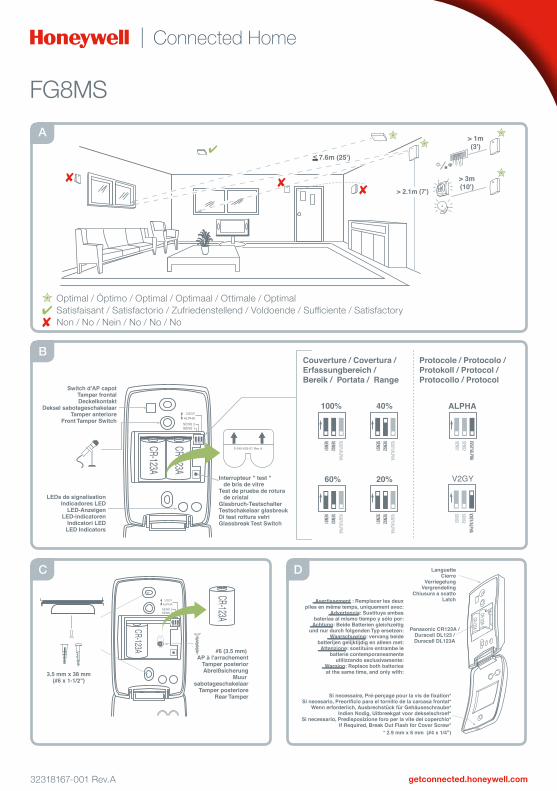
Optimal / Óptimo / Optimal / Optimaal / Ottimale / OptimalSatisfaisant / Satisfactorio / Zufriedenstellend / Voldoende / Sufficiente / SatisfactoryNon / No / Nein / No / No / No
A
B
C D

1 SELECT MOUNTING LOCATIONRefer to A (on page 1) and the following list for mounting guidelines.•Mount the detector between the protected glass and any heavy window coverings that may be present. When heavy window coverings are present, the detector can be mounted on the frame of the window•Do NOT mount the detector:
–on posts or pillars –in rooms with noisy equipment (air compressors, power tools, etc.), if this equipment is operated when the detector is armed –where the detector’s view of the glass may be obstructed unintentionally
2 CONNECT THE BATTERIES (See B on Page 1)3 SELECT PROTOCOL (See B on Page 1)evohome=ALPHA4 SET THE RANGE (See B on Page 1)For best false alarm immunity, measure distance from the intendedmounting location of the detector to the farthest point of glass to beprotected. The maximum distance should be 7.6 m. Set the shortest rangeavailable with DIP switches SENS 1 and SENS 2 that is greater than orequal to measured distance.5 MOUNT THE DETECTOROrient the microphone for the best line-of-site to the protected glass. If ceiling mounted the end with the microphone should face the protectedglass.Important: Not suitable for use on acoustic ceiling tiles if the rear tamperwill be used. Use drywall anchors if not mounting to a wall stud or ceilingjoist. If the rear tamper is used, tamper screw should screw into frame, or a heavy-duty anchor, because the rear tamper requires high breakawayforce.Reinstall the battery (if removed for rear tamper installation), then close and secure the detector front cover.6 TEST MODESTRANSMITTER Test Mode: This test mode shows transmitter activity. It activates upon power-up and when the cover is opened. It remains active for 10 minutes after the tamper switch is closed.GLASSBREAK Test Mode: This test mode allows testing of the glassbreak function. It is activated three ways – upon power-up, by pressing the glassbreak test switch (see B on page 1).For both test modes, refer to the following LED Indicators table.LED INDICATORS (LEDs are only visible in test mode.)
CONDITION RED LED GREEN LEDPower Up ON 1 second ON 1 secondTRANSMITTER test mode(10 minutes)
FlashesBrieflyOnce = ALPHAFlashesBrieflyTwice = V2GY
OFF
GLASSBREAKtest mode(5 minutes1)
Normal OFF Flashes once persecondandFlickers whensound detected
Alarm ON 5 secondsLow battery2
Flashes once persecond
Normal Operation (Not in test modes)
OFF OFF
1 5 minutes after the last sound that causes the green LED to flicker.2 When registered, the FG8MS sends a low battery signal to the panelwhen the battery voltage gets low. Replace the battery. The detectorlow battery indication is approximate only.7 TESTING GLASSBREAK WITHOUT AN FG-701 TESTEREnterGLASSBREAKtestmode.TheGreenLEDwillflashat1Hz.ClaphandsnearthedetectorandtheGreenLEDwillflicker,verifyingthedetector is hearing room noise. To test that that the panel is detecting analarm,taponthedetectorcoverwithafingernailorscrewdriveruntiltheRed LED turns on for 5 seconds.8 REGISTERING THE DETECTOR1.
https://international.mytotalconnectcomfort.com
2.Open and close the front cover.
3.
https://international.mytotalconnectcomfort.com
9 INSTALL COVER SCREW, IF REQUIREDTo secure the front cover after installation, remove the cover breakoutflashandsecurethefrontcoverwitha2.9mmx6.0mmscrew(notprovided.) Refer to D on page 1.10 SPECIFICATIONSProtected Glass Types:NOTE:Minimumsizeforalltypesis28cmx28cm..
Glass Type* Nominal ThicknessMinimum Maximum
Plate 2mm 10mmTempered 3mm 10mmLaminated 1, 3 3mm 14mmWired 6mm 6mmCoated2, 3 3mm 6mmSealed insulating 1, 3 3mm [13mm overall] 6mm[19mmoverall]
* Glass must be framed in the wall or mounted in a barrier at least 0.9m wide.1 Protected only if all plates or panes are broken.2 Coated glass with security films up to 0.35mm (14 mils) thick (including films for solar protection) may be used. Evaluated with the these products: 3M® SCOTCHSHIELD® SH14CLARL – 0.35mm (14 mils), 4 ply film; Film Technologies International, Inc.’s GLASS-GARD GGLL 1200.3 For these glass types, mounting at less than ½ the indicated range setting is recommended. (Example: set SENS 1 and SENS 2 for 4.6 m range, but mount the detector 2.3 m or less from the farthest glass to be protected.)
FG8MS Wireless Glassbreak Detector - Installation Instructions
English
5 20
3
1 2a
3a
1 2
2b
3b
1
1
2
2
x21 2
2.5min
CR123 LITHIUM 3V
CR123
DURACELL
2.5min
2.1m - 2.7m(2.3m)
30cm
1.8m
SEF8MS
x2
WEB
www.
20
SEF8MS
www.
www.
2.5min
CR123 LITHIUM 3V
CR123
DURACELL
5 20
3
1 2a
3a
1 2
2b
3b
1
1
2
2
x21 2
2.5min
CR123 LITHIUM 3V
CR123
DURACELL
2.5min
2.1m - 2.7m(2.3m)
30cm
1.8m
FG8MS
x2
WEB
www.www.
2.5min
CR123 LITHIUM 3V
CR123
DURACELL
FG8MS
www.
1 AUSWAHL DES MONTAGEORTSBeachten Sie bei der Montage die Hinweise unter A (auf Seite 1) sowie die folgende Liste.•MontierenSiedenMelderzwischendemzuschützendenGlasundeventuell vorhandenen schweren Fenstervorhängen. Falls schwere Fenstervorhänge vorhanden sind, kann der Melder am Fensterrahmen befestigt werden.•An folgenden Stellen darf der Melder nicht montiert werden:
–an Pfosten oder Pfeilern –in Räumen mit lauten Maschinen (Luftkompressoren, Werkzeugmaschinenusw.),wenndieseMaschinenbeischarfgeschaltetem Melder betrieben werden –an Stellen, an denen die Möglichkeit besteht, dass die optische Linie zwischenMelderundGlasunbeabsichtigtunterbrochenwird
2 ANSCHLIESSEN DER BATTERIEN (siehe B auf Seite 1)3 AUSWÄHLEN DES PROTOKOLLS (siehe B auf Seite 1)evohome=ALPHA4 EINSTELLEN DER REICHWEITE (siehe B auf Seite 1)Damit Fehlalarme so weit wie möglich verhindert werden, messen Sie denAbstandvomvorgesehenenMontageortdesMeldersbiszudemamweitestenentferntenPunktaufdemGlas,dasgeschütztwerdensoll.Dermaximale Abstand beträgt 7,6 m. Stellen Sie mit den DIP-Schaltern SENS 1undSENS2denkürzestenderverfügbarenMessbereicheein,dergrößer oder gleich dem gemessenen Abstand ist.5 MONTAGE DES MELDERSRichtenSiedasMikrofonmöglichstdirektaufdaszuschützendeGlas.BeiDeckenmontagemussdasEndemitdemMikrofonaufdaszuschützendeGlaszeigen.Wichtig: NichtgeeignetfürdieMontageaufAkustikdeckenplatten,wenndie Abreißsicherung verwendet werden soll. Wenn die Befestigung nicht an einem Wandständer oder einem Deckenträger erfolgt, verwenden Sie Trockenbaudübel.WenndieAbreißsicherungverwendetwerdensoll,mussdieSchraubeindietragendeStrukturodereinenSchwerlastdübelgedreht werden, da die Abreißsicherung eine hohe Ausreißkraft aufnehmenkönnenmuss.SetzenSiedieBatteriewiederein,fallsdiesezurInstallationderAbreißsicherungentferntwurde,schließenSiedieFrontabdeckung des Melders, und sichern Sie diese.6 TESTMODITestmodus SENDER: In diesem Testmodus wird die Funktion des Sendersgeprüft.DerModuswirdbeimEinschaltensowiebeimÖffnender Abdeckung aktiviert und bleibt 10 Minuten nach dem Schließen des Deckelkontakts aktiv.Testmodus GLASBRUCH: IndiesemTestmoduskanndieFunktionzurGlasbruch-Erkennunggeprüftwerden.DerModuswirdaufdreiArtenaktiviert:beimEinschalten,durchDrückendesGlasbruch-Testschalters(siehe Abschnitt B auf Seite 1). In beiden Testmodi gilt die nachstehende LED-Anzeigentabelle.LED-ANZEIGEN(LED-SignalesindnurimTestmoduszusehen.)
ZUSTAND ROT LED GRÜNEN LEDEinschalten 1 Sekunde EIN 1 Sekunde EINTestmodus SENDER(10 Minuten)
Einmaliges Blinken= ALPHAZweimaligesBlinken = V2GY
AUS
TestmodusGLASBRUCH(5 Minuten1)
Normal AUS Blinken mit 1 HertzundFlackern beierkanntemGeräusch
Alarm 5 Sekunden EINBatterie fast leer2
Blinkenmit1Hertz
Normalbetrieb (kein Testmodus)
AUS AUS
1 5 Minuten nach dem letzten Geräusch, das das Flackern der grünen LED ausgelöst hat2 Wenn es geregistriert wird, schickt das FG8MS ein niedriges Batteriesignal zur Verkleidung, wenn die Batteriespannung niedrig erhält. Ersetzen Sie die Batterie. Die niedrige Batterieanzeige des Detektors ist nur ungefähr.7 TESTEN DER GLASBRUCH-ERKENNUNG OHNE TESTER FG-701AktivierenSiedenTestmodusGLASBRUCH.DiegrüneLEDblinktmitderFrequenz1Hz.KlatschenSieinderNähedesMeldersindieHände.DiegrüneLEDflackertundsignalisiertdamit,dassderMeldereinRaumgeräuscherkennt.Umzuprüfen,obauchanderMeldezentraleeinAlarmsignal erkannt wird, klopfen Sie mit dem Fingernagel oder einem Schraubendreher auf das Gehäuse des Melders, bis die rote LED 5 Sekunden lang leuchtet.
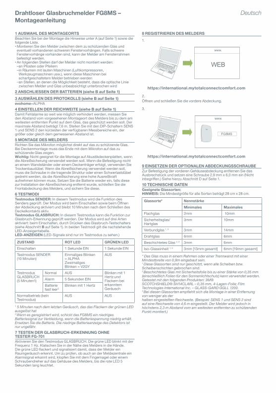
8 REGISTRIEREN DES MELDERS1.
https://international.mytotalconnectcomfort.com
2.ÖffnenundschließenSiedievordereAbdeckung.
3.
https://international.mytotalconnectcomfort.com
9 EINSETZEN DER OPTIONALEN ABDECKUNGSSCHRAUBEZur Befestigung der vorderen Gehäuseabdeckung entfernen Sie dasAusbrechstückundsetzeneineSchraube2,9mmx6,0mmein(Nichtinbegriffen.)SiehehierzuAbschnittDaufSeite1.10 TECHNISCHE DATENGeeignete Glassorten:HINWEIS: DieMindestgrößefüralleSortenbeträgt28cmx28cm.
Glassorte* NennstärkeMinimales Maximales
Flachglas 2mm 10mmSicherheitsglas/Hartglas
3mm 10mm
Verbundglas 1, 3 3mm 14mmDrahtglas 6mm 6mmBeschichtetes Glas 2, 3 3mm 6mmIso-Glaseinheit 1, 3 3mm [13mm gesamt] 6mm[19mmgesamt]
* Das Glas muss in einem Rahmen oder einer Trennwand mit einer Mindestbreite von 0,9m eingebaut sein.1 Diese Glassorten sind nur geschützt, wenn alle Scheiben bzw. Scheibenschichten gebrochen sind.2 Beschichtetes Glas mit Sicherheitsfolie bis zu einer Stärke von 0,35 mm (einschließlich Folien für den Sonnenlichtschutz) kann verwendet werden. Getestet mit den folgenden Produkten: 3M®SCOTCHSHIELD® SH14CLARL – 0,35 mm, 4-Lagen-Folie; Film Technologies International Inc. – GLASS-GARD GGLL 1200.3 Bei diesen Glassorten empfiehlt sich die Montage in einer Entfernung von weniger als derhalben eingestellten Reichweite. (Beispiel: SENS 1 und SENS 2 sind auf eine Reichweite von 4,6 m eingestellt. Der Melder wird jedoch in höchstens 2,3 m Abstand vom am weitesten entfernten zu schützenden Punkt montiert.)
Drahtloser Glasbruchmelder FG8MS – Montageanleitung
Deutsch
5 20
3
1 2a
3a
1 2
2b
3b
1
1
2
2
x21 2
2.5min
CR123 LITHIUM 3V
CR123
DURACELL
2.5min
2.1m - 2.7m(2.3m)
30cm
1.8m
SEF8MS
x2
WEB
www.
20
SEF8MS
www.
www.
2.5min
CR123 LITHIUM 3V
CR123
DURACELL
5 20
3
1 2a
3a
1 2
2b
3b
1
1
2
2
x21 2
2.5min
CR123 LITHIUM 3V
CR123
DURACELL
2.5min
2.1m - 2.7m(2.3m)
30cm
1.8m
FG8MS
x2
WEB
www.www.
2.5min
CR123 LITHIUM 3V
CR123
DURACELL
FG8MS
www.
1 CHOISIR LE LIEU DE POSESe référer à la partie A (en page 1) et à la liste des instructions de montagesuivante.•Monter le détecteur entre la vitre protégée et tout rideau épais recouvrant une fenêtre. Si les fenêtres sont recouvertes d’un rideau épais, le détecteur peut être monté sur le châssis de la fenêtre.•Ne pas placer le détecteur :
–sur des poteaux ou des piliers –dans des pièces munies d’appareils bruyants (compresseurs d’air, outils électriques, etc.), si ces appareils fonctionnent en même temps que le détecteur –lorsque le détecteur n’a pas de vue directe sur la fenêtre, obstruée de manière non intentionnellee
2 METTRE LES PILES EN PLACE (Se référer à la partie B en page 1)3 CHOISIR LE PROTOCOLE (Se référer à la partie B en page 1)evohome=ALPHA4 REGLER LA SENSIBILITE (Se référer à la partie B en page 1)Pour obtenir la meilleure immunité aux fausses alarmes, mesurer la distance entre le lieu envisagé pour la pose du détecteur et la vitre à protéger la plus éloignée. La distance maximum doit être de 7,6 m. Régler la plage la plus courte disponible sur les interrupteurs DIP SENS 1 et SENS 2, supérieure ou égale à la distance mesurée.5 MONTER LE DETECTEUROrienter le microphone vers la vitre protégée pour obtenir la meilleure visibilité. Si le microphone est positionné sur le plafond, son extrémité doit être face à la vitre protégée.Important : L’autoprotection à l’arrachement n’est pas prévue pour êtreutiliséesurdesdallesdefaux-plafond.Utiliserundispositifdefixationpour les murs creux s’il n’est pas installé sur un support solide. Si l’AP àl’arrachement est utilisée, la vis de sécurité doit se visser dans une partiesolide et résistante, car l’autoprotection à l’arrachement demande une résistance importante pour fonctionner correctement.Replacer les piles (si elles ont été ôtées pour installer l’AP à l’arrachement),puisfermeretfixercorrectementlafaceavantdudétecteur.6 MODES TESTMode test du TRANSMETTEUR :Cemodetestmontrel’activitédutransmetteur. Il s’active lorsqu’il est mis sous tension et que le boîtier est ouvert. Il reste actif pendant 10 minutes après la fermeture de l’autoprotection.Mode test du BRIS DE VITRE : Cemodetestpermetdetesterlafonctionbris de vitre. Il s’active de trois façons : à la mise sous tension, en appuyant sur l’interrupteur « test » de bris de vitre (Se référer à la partie Benpage1).Pourlesdeuxmodes,consultezletableaudevisualisationdes LEDs.Indications des LEDs (Les LEDs ne sont visibles qu’en mode test.)
CONDITION ROUGE LED VERTE LEDMise sous tension ON 1 seconde ON 1 secondeMode test du TRANSMETTEUR (10 minutes)
S’allume brièvementune fois = ALPHAS’allume brièvementdeux fois = V2GY
OFF
Mode test duBRIS DE VITRE(5 minutes1)
Normal OFF S’allume une foispar seconde etClignotelorsqu’unson est émis
Alarme ON 5 secondesPiles faible2
S’allume une fois parseconde
Fonctionnement normal(hors modes test)
OFF OFF
1 5 minutes après le dernier son émis qui fait clignoter la LED verte.2 Une fois enregistré, le FG8MS fera parvenir un message de pile basse quand le niveau de tension de la pile deviendra trop bas. Remplacer la pile. L’information de pile basse est approximative.7 TESTER LE BRIS DE VITRE SANS LE SIMULATEUR FG-701EntrerenmodetestBRISDEVITRE.LaLEDvertes’allumeraà1Hz.TaperdesmainsàproximitédudétecteuretlaLEDverteclignotera,vérifiantquele détecteur reçoit bien les bruits de la pièce. Pout tester si le dispositif détecte une alarme, taper le boîtier du détecteur avec un ongle ou un tournevis jusqu’à ce que la LED rouge s’allume pendant 5 secondes.
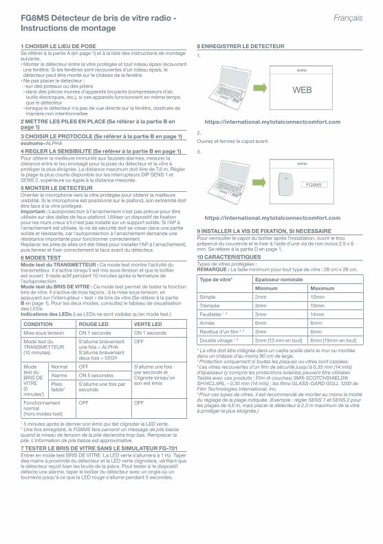
8 ENREGISTRER LE DETECTEUR1.
https://international.mytotalconnectcomfort.com
2.Ouvrezetfermezlecapotavant.
3.
https://international.mytotalconnectcomfort.com
9 INSTALLER LA VIS DE FIXATION, SI NECESSAIREPour verrouiller le capot du boîtier après l’installation, ouvrir le trou prépercéducouvercleetlefixeràl’aided’unevisdenoninclus2.9x6mm. Se référer à la partie D en page 1.10 CARACTERISTIQUESTypes de vitres protégées :REMARQUE : Latailleminimumpourtouttypedevitre:28cmx28cm.
Type de vitre* Epaisseur nominaleMinimum Maximum
Simple 2mm 10mmTrempée 3mm 10mmFeuilletée 1, 3 3mm 14mmArmée 6mm 6mmRevêtued’unfilm2, 3 3mm 6mmDouble vitrage 1, 3 3mm [13 mm en tout] 6mm[19mmentout]
* La vitre doit être intégrée dans un cadre scellé dans le mur ou montée dans un châssis d’au moins 90 cm de large.1 Protection uniquement si toutes les plaques ou vitres sont cassées.2 Les vitres recouvertes d’un film de sécurité jusqu’à 0,35 mm (14 mils) d’épaisseur (y compris les protections solaires) peuvent être utilisées. Testés avec ces produits : Film (4 couches) 3M® SCOTCHSHIELD® SH14CLARL – 0,35 mm (14 mils) ; les films GLASS-GARD GGLL 1200 de Film Technologies International, Inc.3 Pour ces types de vitres, il est recommandé de monter au moins la moitié du réglage de la plage indiquée. (Exemple : régler SENS 1 et SENS 2 pour les plages de 4,6 m, mais placer le détecteur à 2,3 m maximum de la vitre à protéger la plus éloignée.)
FG8MS Détecteur de bris de vitre radio - Instructions de montage
Français
5 20
3
1 2a
3a
1 2
2b
3b
1
1
2
2
x21 2
2.5min
CR123 LITHIUM 3V
CR123
DURACELL
2.5min
2.1m - 2.7m(2.3m)
30cm
1.8m
SEF8MS
x2
WEB
www.
20
SEF8MS
www.
www.
2.5min
CR123 LITHIUM 3V
CR123
DURACELL
5 20
3
1 2a
3a
1 2
2b
3b
1
1
2
2
x21 2
2.5min
CR123 LITHIUM 3V
CR123
DURACELL
2.5min
2.1m - 2.7m(2.3m)
30cm
1.8m
FG8MS
x2
WEB
www.www.
2.5min
CR123 LITHIUM 3V
CR123
DURACELL
FG8MS
www.
1 SELECTEER EEN LOCATIERaadpleeg A (op pagina 1) en de volgende lijst voor montage richtlijnen.•Plaatsdedetectortussenhettebewakenglasenzwaregordijnen,indienaanwezig.Wanneererzwaregordijnenaanwezigzijn,kandedetectorophetkozijnwordengeplaatst.•Plaats de detector NIET:
–op palen of pilaren –inruimtesmetapparatendielawaaiveroorzaken(luchtcompressoren,elektrischgereedschapenzovoort)wanneerdezeapparatengebruiktworden terwijl de detector is geactiveerd –waarhetzichtvandedetectorophetglasonbedoeldkanwordengeblokkeerd
2 DE BATTERIJEN AANSLUITEN (zie B op pagina 1)3 PROTOCOL SELECTEREN (zie B op pagina 1)evohome=ALPHA4 HET BEREIK INSTELLEN (zie B op pagina 1)Voor de beste bescherming tegen ongewenste alarmen meet u de afstandtussen de locatie van de detector en het verst verwijderde glas dat moetworden beschermd. De maximale afstand is 7,6m. Stel met DIPschakelaars SENS 1 en SENS 2 de kortste beschikbare afstand in welke gelijk is aan of groter dan de gemeten afstand.5 DE DETECTOR PLAATSENRichtdemicrofoonzogoedmogelijknaarhetbeschermdeglas.Bijplafondmontage, moet het uiteinde met microfoon naar het te beschermen glas gericht worden.Belangrijk: niet geschikt voor gebruik op akoestische plafondtegels alsde sabotageschakelaar aan de achterkant wordt gebruikt. Gebruikgipsplaatpluggen als u de detector niet aan een rachel of een steunbalkbevestigt. Als u de muur sabotageschakelaar gebruikt, moet u de schroefinderachelofsteunbalkofineenzwaregipsplaatplugplaatsen,omdatdedetector een hoge lostrekkracht vereist.Plaatsdebatterijopnieuw(alsdezeisverwijderdvoordeinstallatievandemuur sabotageschakelaar), sluit de klep en sluit de deksel aan devoorzijdevandedetector.6 TESTMODITestmodus ZENDER: Dezetestmodustoontdeactiviteitvandezender.De modus wordt geactiveerd bij opstarten en wanneer de deksel wordtgeopend. De modus blijft tien minuten nadat de dekselsabotageschakelaar is ingedrukt actief.Testmodus GLASBREUK: Dezemodustestdeglasbreukfunctie.Demodus wordt op drie manieren geactiveerd: bij opstarten, door detestschakelaarvoorglasbreukintedrukken(zieB op pagina 1) en opafstand met behulp van de FG-701-glasbreuktester.Raadpleeg voor beide modi de volgende LED-indicatietabel.LEDS-INDICATOREN(LEDszijnalleenzichtbaarintestmodus.)
TOESTAND ROOD LED GROEN LEDOpstarten 1 seconde AAN 1 seconde AANTestmodus ZENDER(10 minuten)
Knippert eenmaalkort = ALFAKnippert tweemaalkort = V2GY
UIT
TestmodusGLASBREUK(5 minuten1)
Normaal UIT Knippert eenmaalper secondeenKnippert bijgedetecteerd geluid
Alarm AAN gedurende 5seconde
Batterij bijnaleeg2
Knippert eenmaalper seconde
Normale werking (niet in testmodi)
UIT UIT
1 5 minuten na het laatste geluid waardoor de groene LED heeft geknipperd.2 Wanneer geregistreerd, verzendt FG8MS een laag batterijsignaal naar hetpaneel wanneer het batterijvoltage laag wordt. Vervang de batterij. Deaanwijzing van de detector lage batterij is slechts benaderend.7 GLASBREUK TESTEN ZONDER EEN FG-701-TESTERSchakel de testmodus GLASBREUK. De groene LED knippert eenmaalper seconde. Wanneer u in de buurt van de detector in uw handen klapt,knippert de groene LED, wat aangeeft dat de detector geluid detecteert.Tik om te testen dat het paneel een alarm detecteert met een nagel of eenschroevendraaier op de kap van de detector totdat de rode LED 5seconden blijft branden.
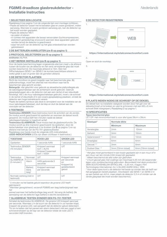
8 DE DETECTOR REGISTREREN1.
https://international.mytotalconnectcomfort.com
2.Open en sluit de voorklep.
3.
https://international.mytotalconnectcomfort.com
9 PLAATS INDIEN NODIG DE SCHROEF OP DE DEKSELDedekselkannainstallatievastgezetwordendoorhetgatvoordedekselschroef uit te breken en vast te schroeven met een M3 x 6 mmschroef (Niet inbegrepen.) Raadpleeg D op pagina 1.10 SPECIFICATIESTypes beschermd glas:LETOP:Hetminimumformaatisvooralletypes28cmx28cm.
Glastype* Normale dikteMinimum Maximum
Vensterglas 2mm 10mmGehard 3mm 10mmGelamineerd 1, 3 3mm 14mmDraadglas 6mm 6mmGecoat 2, 3 3mm 6mmDubbel Glas 1, 3 3mm [13mm totaal] 6mm[19mmtotaal]
* Het glas moet gemonteerd in een kozijn geplaatst zijn in een muur of in een muur van ten minste 0,9m breed zijn geplaatst.1 Alleen beschermd als alle ruiten zijn gebroken.2 U kunt gecoat glas met coatings van maximaal 0,35 mm dik (waaronder lagen voor zonbescherming) gebruiken. Beoordeeld met deze producten: 3M® SCOTCHSHIELD® SH14CLARL – 0,35 mm, 4 lagen; Film Technologies International, Inc.’s GLASS-GARD GGLL 1200.3 Voor deze types kunt u de detector het beste op minder dan de helft van het aangegeven bereik plaatsen. (Voorbeeld: stel SENS 1 en SENS 2 in op een bereik van 4,6 m, maar plaats de detector 2,3 m of minder van de verste glasplaat die moet worden beschermd.)
FG8MS draadloze glasbreukdetector - Installatie Instructies
Nederlands
5 20
3
1 2a
3a
1 2
2b
3b
1
1
2
2
x21 2
2.5min
CR123 LITHIUM 3V
CR123
DURACELL
2.5min
2.1m - 2.7m(2.3m)
30cm
1.8m
SEF8MS
x2
WEB
www.
20
SEF8MS
www.
www.
2.5min
CR123 LITHIUM 3V
CR123
DURACELL
5 20
3
1 2a
3a
1 2
2b
3b
1
1
2
2
x21 2
2.5min
CR123 LITHIUM 3V
CR123
DURACELL
2.5min
2.1m - 2.7m(2.3m)
30cm
1.8m
FG8MS
x2
WEB
www.www.
2.5min
CR123 LITHIUM 3V
CR123
DURACELL
FG8MS
www.
1 SELEZIONARE LA POSIZIONE DI MONTAGGIOPer le linee guida per il montaggio, fare riferimento al riquadro A (pagina 1)e all’elenco seguente.•Montare il rilevatore tra il vetro protetto ed eventuali tendaggi pesanti presenti.Inpresenzaditendaggipesanti,èpossibilemontareilrilevatoresultelaiodellafinestra.•NON montare il rilevatore:
–su stipiti o pilastri; –inambienticonapparecchiaturerumorose(compressorid’aria,attrezzielettrici,ecosìvia),setaliapparecchiaturesonoinfunzionequandoilrilevatore è attivo; –in punti in cui è possibile che la visuale del rilevatore sul vetro venga involontariamente ostruita
2 COLLEGARE LE BATTERIE (vedere il riquadro B a pagina 1)3 SELEZIONARE IL PROTOCOLLO (vedere il riquadro B a pagina 1)evohome=ALPHA4 IMPOSTARE LA PORTATA (vedere il riquadro B a pagina 1)Perridurreilrischiodifalsiallarmi,misurareladistanzatralaposizionedimontaggio del rilevatore desiderata e il punto più lontano del vetro daproteggere.Ladistanzamassimaconsentitaèdi7,6m.Utilizzandogliinterruttori DIP SENS 1 e SENS 2, impostare il valore di portata minoredisponibileinmodochesiamaggioreougualealladistanzamisurata.5 MONTARE IL RILEVATOREOrientare il microfono in modo che sia diretto verso il vetro protetto. In casodimontaggioasoffitto,l’estremitàconilmicrofonodeveessererivolta verso il vetro protetto.Importante:nonadattoall’usosupannellipercontrosoffittifonoassorbentiincasodiutilizzodeltamperposteriore.Utilizzaregliancoraggi per cartongesso se il rilevatore non viene montato su montanti otravettidelsoffitto.Incasodiutilizzodeltamperposteriore,inserireneltelaio una vite antimanomissione o un ancoraggio ultraresistente, poiché il tamperposteriorerichiedeunosforzodiuscitaelevato.Riposizionarelabatteria(serimossaperl’installazionedeltamperposteriore), quindi chiudere saldamente il coperchio anteriore del rilevatore.6 MODALITÀ DI TESTModalità di test TRASMETTITORE: questa modalità di test mostra l’attività del trasmettitore. Viene attivata all’accensione e all’apertura del coperchioerimaneattivaper10minutidopol’azionamentodeltamperantimanomissione.Modalità di test ROTTURA VETRI: questa modalità di test consente diverificarelafunzionerotturavetrievieneattivataintremodi:all’accensione, mediante l’interruttore di test rottura vetri (vedere il riquadro B a pagina 1). LED riportata di seguito.INDICATORI LED (I LED sono visibili unicamente in modalità di test)
CONDIZIONE ROSSO LED VERDE LEDAccensione ACCESO
1 secondoACCESO1 secondo
Modalità di testTRASMETTITORE(10 minuti)
Un breve lampeggio= ALPHADue brevi lampeggi= V2GY
OFF
Modalità di testROTTURAVETRI(5 minuti1)
Normale OFF Un lampeggio alsecondoeSfarfallio quandoviene rilevato unrumore
Alarme ACCESO5secondiBatteriascarica2
Un lampeggio alsecondo
Funzionamentonormale (non inmodalità di test)
OFF OFF
1 5 minuti dopo l’ultimo rumore che ha causato lo sfarfallio del LED verde.2 Una volta registrato, il FG8MS trasmette un segnale basso della batteria al pannello quando la tensione della batteria ottiene bassa. Sostituisca la batteria. L’indicazione bassa della batteria del rivelatore è soltanto approssimativa.7 TEST DI ROTTURA VETRI SENZA UNITÀ FG-701Accedere alla modalità di test ROTTURA VETRI. Il LED verde lampeggia a1Hz.BatterelemaninellevicinanzedelrilevatoreeverificarecheilLEDverde produca uno sfarfallio, a conferma che il rumore ambientale è statorilevato.Perverificareilrilevamentodiallarmidapartedellacentrale,picchiettare sul coperchio del rilevatore con un’unghia o con un cacciavitefinchéilLEDrossononrimangaaccesoper5secondi.
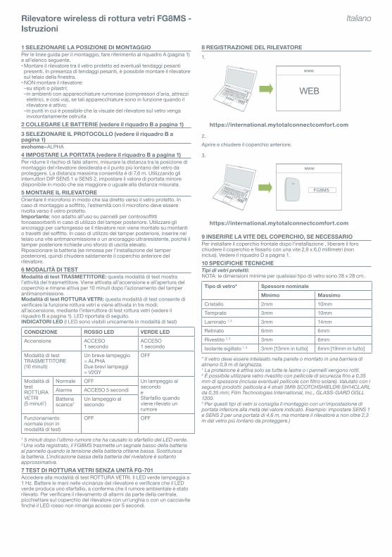
8 REGISTRAZIONE DEL RILEVATORE1.
https://international.mytotalconnectcomfort.com
2.Aprire e chiudere il coperchio anteriore.
3.
https://international.mytotalconnectcomfort.com
9 INSERIRE LA VITE DEL COPERCHIO, SE NECESSARIOPerinstallareilcoperchiofrontaledopol’installazione,liberareilforochiudereilcoperchioefissarloconunavite2,9x6,0millimetri(noninclus). Vedere il riquadro D a pagina 1.10 SPECIFICHE TECNICHETipi di vetri protetti:NOTA:ledimensioniminimeperqualsiasitipodivetrosono28x28cm..
Tipo di vetro* Spessore nominaleMinimo Massimo
Cristallo 2mm 10mmTemprato 3mm 10mmLaminato 1, 3 3mm 14mmRetinato 6mm 6mmRivestito 2, 3 3mm 6mmIsolante sigillato 1, 3 3mm [13mm in tutto] 6mm[19mmintutto]
* Il vetro deve essere intelaiato nella parete o montato in una barriera di almeno 0,9 m di larghezza.1 La protezione è attiva solo se tutte le lastre o i pannelli vengono rotti.2 È possibile utilizzare vetro rivestito con pellicole di sicurezza fino a 0,35 mm di spessore (incluse eventuali pellicole con filtro solare). Valutato con i seguenti prodotti: pellicola a 4 strati 3M® SCOTCHSHIELD® SH14CLARL da 0,35 mm; Film Technologies International, Inc., GLASS-GARD GGLL 1200.3 Per questi tipi di vetri si consiglia il montaggio con un’impostazione di portata inferiore alla metà del valore indicato. Esempio: impostare SENS 1 e SENS 2 per una portata di 4,6 m, ma montare il rilevatore a non oltre 2,3 m dal vetro più lontano da proteggere.)
Rilevatore wireless di rottura vetri FG8MS - Istruzioni
Italiano
5 20
3
1 2a
3a
1 2
2b
3b
1
1
2
2
x21 2
2.5min
CR123 LITHIUM 3V
CR123
DURACELL
2.5min
2.1m - 2.7m(2.3m)
30cm
1.8m
SEF8MS
x2
WEB
www.
20
SEF8MS
www.
www.
2.5min
CR123 LITHIUM 3V
CR123
DURACELL
5 20
3
1 2a
3a
1 2
2b
3b
1
1
2
2
x21 2
2.5min
CR123 LITHIUM 3V
CR123
DURACELL
2.5min
2.1m - 2.7m(2.3m)
30cm
1.8m
FG8MS
x2
WEB
www.www.
2.5min
CR123 LITHIUM 3V
CR123
DURACELL
FG8MS
www.
1 SELECCIONAR LA UBICACIÓN DE MONTAJEConsulteA(enlapágina1)ylasiguientelistaparainstruccionesdemontaje.•Monte el detector entre el cristal a proteger y cualquier cortina existente.Si hay cortinas pesadas, el detector puede montarse en el marco de la ventana•NOmonteeldetector:
–en postes o pilares –en salas con equipos ruidosos (compresores de aire, herramientas eléctricas,etc.),sidichosequiposseutilizanmientraseldetectorestáarmado –si la visión del cristal por parte del detector puede haberse obstruido accidentalmente
2 CONEXIÓN DE LAS BATERÍAS (consulte B en la página 1)3 SELECCIÓN DE PROTOCOLO (consulte B en la página 1)evohome=ALPHA4 AJUSTE DE LA COBERTURA (consulte B en la página 1)Para una mejor inmunidad a falsas alarmas, mida la distancia entre la ubicacióndemontajeprevistadeldetectoryelpuntodelcristalmáslejanoquesevaaproteger.Ladistanciamáximadeberáserde7,6m.AjustelacoberturamáscortaposibleconlosinterruptoresDIPSENS1ySENS 2 que sea mayor o igual a la distancia medida.5 MONTAJE DEL DETECTOROriente el micrófono para obtener la mejor línea de visión del cristal protegido.Sisemontaeneltecho,elextremoconelmicrófonodeberásituarse frente al cristal protegido.Importante: Su uso no resulta adecuado en techo practicables si se. utilizaeltamperposterior.Utiliceanclajesdemamposteríasinosevaamontarenunaparedounavigadetecho.Siseutilizaeltamper,eltornillodeseguridaddeberáatornillarsealaestructuraoaunanclajepesado,yaquedichodispositivorequiereunafuerzaderupturaelevada.Vuelva a instalar la batería (si se ha retirado para la instalación del tamper) ydespués,cierreyfijelacubiertafrontaldeldetector.6 MODOS DE PRUEBAModo de prueba de TRANSMISOR: Este modo de prueba muestra la actividad del transmisor. Se activa al encenderse el aparato y abrirse la cubierta. Permanece activo durante 10 minutos después de haberse cerrado el interruptor de seguridad.Modo de prueba de ROTURA DE CRISTAL: Este modo de prueba permite probar la función de rotura de cristal. Se activa de tres formas: al encender el aparato, al pulsar el interruptor de prueba de rotura de cristal (consulte Benlapágina1).Paraambosmodosdeprueba,consultelasiguiente tabla de indicadores LED.INDICADORES LED (Los LED sólo son visibles en el modo de prueba.)
CONDICIÓN LED ROJO LED VERDEEncendido ENCENDIDO1
segundoENCENDIDO1segundo
Modo de prueba deTRANSMISOR(10 minutos)
Parpadeabrevementeunavez=ALPHA Parpadeabrevemente dosveces = V2GY
OFF
Modo de pruebade ROTURA DECRISTAL:(5 minutos1)
Normal OFF Parpadeaunavezpor segundoyParpadea cuandose detecta sonido
Alarma ENCENDIDO5segundos
Batería baja2
Parpadeaunavezpor segundo
Funcionamiento normal (no enmodos de prueba)
OFF OFF
1 5 minutos después del último sonido que hace parpadear el LED verde.2 Cuando está colocado, el FG8MS envía una señal baja de la batería al panel cuando el voltaje de la batería es muy bajo. Substituya la batería. La indicación baja de la batería del detector es aproximada solamente.7 PRUEBA DE ROTURA DE CRISTAL SIN UN DISPOSITIVO DE PRUEBA FG-701AccedaalmododepruebadeROTURADECRISTAL.ElLEDverdeparpadearáa1Hz.DéunapalmadajuntoaldetectoryelLEDverdeparpadeará,comprobándoseasísieldetectordetectaelruidodelasala.Para comprobar si el panel detecta una alarma, golpee ligeramente la carcasa del detector con la uña o con un destornillador hasta que el LED rojo se encienda durante 5 segundos.
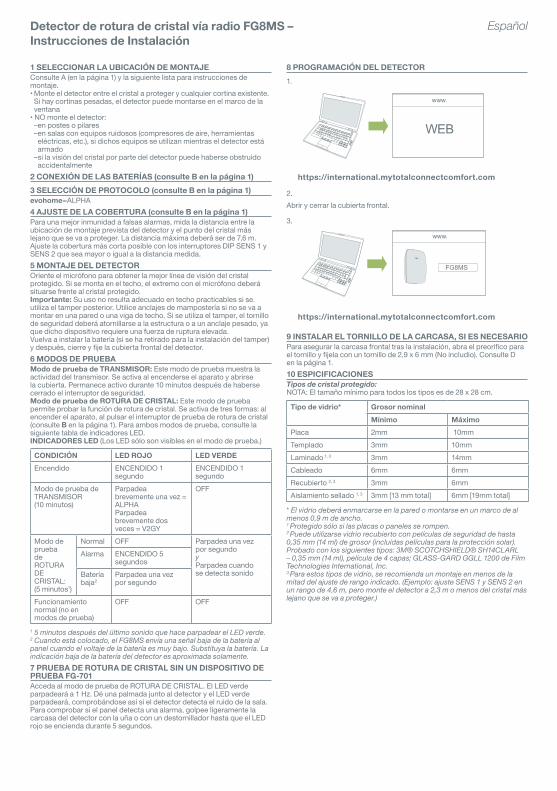
8 PROGRAMACIÓN DEL DETECTOR1.
https://international.mytotalconnectcomfort.com
2.Abrir y cerrar la cubierta frontal.
3.
https://international.mytotalconnectcomfort.com
9 INSTALAR EL TORNILLO DE LA CARCASA, SI ES NECESARIOParaasegurarlacarcasafrontaltraslainstalación,abraelpreorificoparaeltornilloyfijelaconuntornillode2,9x6mm(Noincludio).ConsulteDenlapágina1.10 ESPICIFICACIONESTipos de cristal protegido:NOTA:Eltamañomínimoparatodoslostiposesde28x28cm.
Tipo de vidrio* Grosor nominalMínimo Máximo
Placa 2mm 10mmTemplado 3mm 10mmLaminado 1, 3 3mm 14mmCableado 6mm 6mmRecubierto 2, 3 3mm 6mmAislamiento sellado 1, 3 3mm [13 mm total] 6mm[19mmtotal]
* El vidrio deberá enmarcarse en la pared o montarse en un marco de al menos 0,9 m de ancho.1 Protegido sólo si las placas o paneles se rompen.2 Puede utilizarse vidrio recubierto con películas de seguridad de hasta 0,35 mm (14 ml) de grosor (incluidas películas para la protección solar). Probado con los siguientes tipos: 3M® SCOTCHSHIELD® SH14CLARL – 0,35 mm (14 ml), película de 4 capas; GLASS-GARD GGLL 1200 de Film Technologies International, Inc.3 Para estos tipos de vidrio, se recomienda un montaje en menos de la mitad del ajuste de rango indicado. (Ejemplo: ajuste SENS 1 y SENS 2 en un rango de 4,6 m, pero monte el detector a 2,3 m o menos del cristal más lejano que se va a proteger.)
Detector de rotura de cristal vía radio FG8MS – Instrucciones de Instalación
5 20
3
1 2a
3a
1 2
2b
3b
1
1
2
2
x21 2
2.5min
CR123 LITHIUM 3V
CR123
DURACELL
2.5min
2.1m - 2.7m(2.3m)
30cm
1.8m
SEF8MS
x2
WEB
www.
20
SEF8MS
www.
www.
2.5min
CR123 LITHIUM 3V
CR123
DURACELL
Español
5 20
3
1 2a
3a
1 2
2b
3b
1
1
2
2
x21 2
2.5min
CR123 LITHIUM 3V
CR123
DURACELL
2.5min
2.1m - 2.7m(2.3m)
30cm
1.8m
FG8MS
x2
WEB
www.www.
2.5min
CR123 LITHIUM 3V
CR123
DURACELL
FG8MS
www.
FG8M
Wire
less
Gla
ssbr
eak
Det
ecto
r - In
stal
latio
n In
stru
ctio
ns
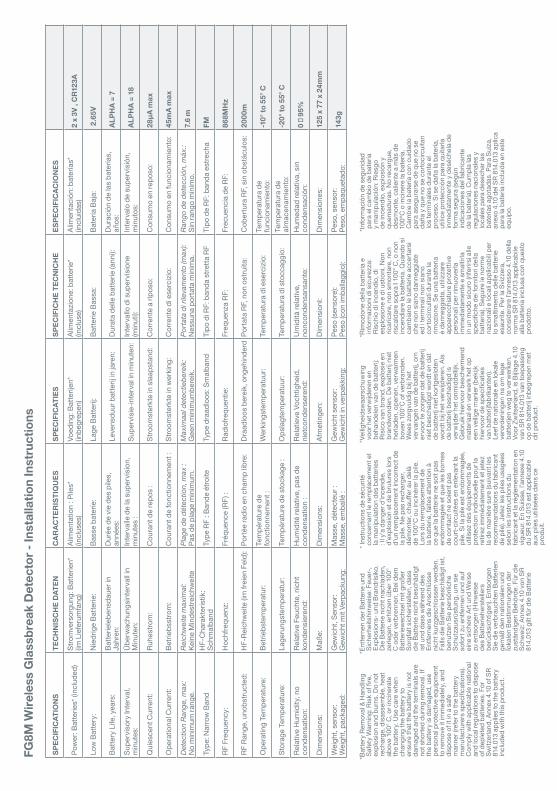
SPEC
IFIC
ATIO
NS
TEC
HN
ISC
HE
DAT
ENC
ARAC
TER
ISTI
QU
ESSP
ECIF
ICAT
IES
SPEC
IFIC
HE
TEC
NIC
HE
ESPE
CIF
ICAC
ION
ES
Pow
er: B
atte
ries*
(inc
lude
d)
Stro
mve
rsor
gung
: Bat
terie
n*(im
Lie
feru
mfa
ng)
Alim
enta
tion
: Pile
s*(in
clus
es)
Voed
ing:
Bat
terij
en*
(inbe
grep
en)
Alim
enta
zione
: bat
terie
*(in
clus
e)Al
imen
taci
ón: b
ater
ías*
(incl
uida
s)2
x 3V
, C
R123
A
Low
Bat
tery
:N
iedr
ige
Batte
rie:
Bass
e ba
teríe
:La
ge B
atte
rij:
Batte
rie B
assa
: Ba
tería
Baj
a:
2.6
5V
Batte
ry L
ife, y
ears
: Ba
tterie
lebe
nsda
uer i
nJa
hren
:D
urée
de
vie
des
pile
s,an
nées
:Le
vens
duur
bat
terij
in ja
ren:
D
urat
a de
lle b
atte
rie (a
nni):
D
urac
ión
de la
s ba
tería
s,añ
os:
ALPH
A =
7
Supe
rvis
ory
Inte
rval
,m
inut
es:
Übe
rwac
hung
sint
erva
ll in
Min
uten
:In
terv
alle
de
la s
uper
visi
on,
min
utes
:Su
perv
isie
-inte
rval
in m
inut
en:
Inte
rval
lo d
i sup
ervi
sion
e(m
inut
i):In
terv
alo
de s
uper
visi
ón,
min
utos
:AL
PHA
= 18
Qui
esce
nt C
urre
nt:
Ruhe
stro
m:
Cou
rant
de
repo
s :
Stro
omst
erkt
e in
sla
apst
and:
C
orre
nte
a rip
oso:
C
onsu
mo
en re
poso
: 28
μA m
ax
Ope
ratio
nal C
urre
nt:
Betri
ebss
trom
: C
oura
nt d
e fo
nctio
nnem
ent :
St
room
ster
kte
in w
erki
ng:
Cor
rent
e di
ese
rcizi
o:
Con
sum
o en
func
iona
mie
nto:
45
mA
max
Det
ectio
n Ra
nge,
max
:N
o m
inim
um ra
nge.
Reic
hwei
te m
axim
al:
Kein
e M
inde
stre
ichw
eite
Plag
e de
dét
ectio
n, m
ax :
Pas
de p
lage
min
imum
.M
axim
aal d
etec
tiebe
reik:
Gee
n m
inim
umbe
reik
.Po
rtata
di r
ileva
men
to (m
ax):
Nes
suna
por
tata
min
ima.
Rang
o de
det
ecci
ón, m
áx.:
Sin
rang
o m
ínim
o.7.
6 m
Type
: Nar
row
Ban
dH
F-C
hara
kter
istik
: Sc
hmal
band
Type
RF
: Ban
de é
troite
Type
dra
adlo
os: S
mal
band
Tipo
di R
F: b
anda
stre
tta R
FTi
po d
e RF
: ban
da e
stre
cha
FM
RF F
requ
ency
: H
ochf
requ
enz:
Fr
éque
nce
(RF)
: Ra
diof
requ
entie
:Fr
eque
nza
RF:
Frec
uenc
ia d
e RF
: 86
8MH
z
RF R
ange
, uno
bstru
cted
: H
F-Re
ichw
eite
(im
frei
en F
eld)
: Po
rtée
radi
o en
cha
mp
libre
: D
raad
loos
ber
eik,
ong
ehin
derd
Porta
ta R
F, n
on o
stru
ita:
Cob
ertu
ra R
F, s
in o
bstá
culo
s:
2000
m
Ope
ratin
g Te
mpe
ratu
re:
Betri
ebst
empe
ratu
r: Te
mpé
ratu
re d
efo
nctio
nnem
ent :
Wer
king
stem
pera
tuur
: Te
mpe
ratu
ra d
i ese
rcizi
o:
Tem
pera
tura
de
func
iona
mie
nto:
-10°
to 5
5° C
Stor
age
Tem
pera
ture
: La
geru
ngst
empe
ratu
r: Te
mpé
ratu
re d
e st
ocka
ge :
Ops
lagt
empe
ratu
ur:
Tem
pera
tura
di s
tocc
aggi
o:
Tem
pera
tura
de
alm
acen
amie
nto:
-20°
to 5
5° C
Rela
tive
Hum
idity
, no
cond
ensa
tion:
Rela
tive
Feuc
hte,
nic
htko
nden
sier
end:
Hum
idité
rela
tive,
pas
de
cond
ensa
tion
:Re
latie
ve V
ocht
ighe
id,
niet
cond
ense
rend
:U
mid
ità re
lativ
e,
nonc
onde
nsan
sant
e:H
umed
ad re
lativ
a, s
inco
nden
saci
ón:
0 �
95%
Dim
ensi
ons:
M
aße:
D
imen
sion
s:
Afm
etin
gen:
D
imen
sion
I: D
imen
sion
es:
125
x 77
x 2
4mm
Wei
ght,
sens
or:
Wei
ght,
pack
aged
:G
ewic
ht, S
enso
r:G
ewic
ht m
it Ve
rpac
kung
:M
asse
, dét
ecte
ur :
Mas
se, e
mba
llé :
Gew
icht
sen
sor:
Gew
icht
in v
erpa
kkin
g:Pe
so (s
enso
re):
Peso
(con
imba
llagg
io):
Peso
, sen
sor:
Peso
, em
paqu
etad
o:14
3g
*Bat
tery
Rem
oval
& H
andl
ing
Safe
ty W
arni
ng: R
isk
of fi
re,
expl
osio
n an
d bu
rns.
Do
not
rech
arge
, dis
asse
mbl
e, h
eat
abov
e 10
0° C
, or i
ncin
erat
e th
e ba
ttery
. Use
car
e w
hen
chan
ging
the
batte
ry to
ensu
re th
at th
e ba
ttery
is n
ot
dam
aged
and
the
term
inal
s ar
e no
t sho
rted
durin
g re
mov
al. I
f th
e ba
ttery
is d
amag
ed, u
se
pers
onal
pro
tect
ive e
quip
men
t to
rem
ove
it im
med
iate
ly, a
nd
disp
ose
of it
in a
saf
em
anne
r (re
fer t
o th
e ba
ttery
m
anuf
actu
rers
spe
cifi c
atio
ns).
Com
ply
with
app
licab
le n
atio
nal
and
loca
l reg
ulat
ions
to d
ispo
se
of d
eple
ted
batte
ries.
For
Sw
itzer
land
, Ann
ex 4
.10 o
f SR
814.
013
appl
ies
to th
e ba
ttery
in
clud
ed w
ith th
is pr
oduc
t.
*Ent
fern
en d
er B
atte
rie u
nd
Sich
erhe
itshi
nwei
se: F
euer
-, Ex
plos
ions
- und
Bra
ndris
iko.
D
ie B
atte
rie n
icht
nac
hlad
en,
zerle
gen,
erh
itzen
übe
r 100
° C
oder
ver
bren
nen.
Bei
dem
Ba
tterie
wec
hsel
mit
groß
erSo
rgfa
lt si
cher
stel
len,
das
s di
e Ba
tterie
nic
ht b
esch
ädig
t is
t und
das
s w
ähre
nd d
es
Entfe
rnen
s di
e An
schl
üsse
ni
cht k
urzg
esch
loss
en w
erde
n.
Falls
die
Bat
terie
bes
chäd
igt i
st,
benu
tzen
Sie
per
sönl
iche
Schu
tzau
srüs
tung
, um
sie
so
fort
zu e
ntfe
rnen
und
auf
ei
ne s
iche
re A
rt un
d W
eise
zu
ent
sorg
en (H
inw
eise
de
s Ba
tterie
hers
telle
rs
berü
cksi
chtig
en).
Ents
orge
n Si
e di
e ve
rbra
ucht
en B
atte
rien
gem
äß d
en n
atio
nale
n un
d lo
kale
n Be
stim
mun
gen
der
zust
ändi
gen
Behö
rde.
Für
die
Sc
hwei
z: A
nnex
4.10
von
SR
814.
013
gilt
für d
ie B
atte
rie
* Ins
truct
ions
de
sécu
rité
conc
erna
nt le
rem
plac
emen
t et
la m
anip
ulat
ion
des
batte
ries
: Il y
’a d
ange
r d’in
cend
ie,
d’ex
plos
ion
et d
e br
ulur
es lo
rs
d’un
rem
plac
emen
t inc
orre
ct d
e la
pile
. Ne
pas
rech
arge
r,dé
mon
ter,
chau
ff er a
u de
là
de 1
00°C
ou
inci
nére
r la
pile
. Lo
rs d
u re
mpl
acem
ent d
e la
bat
terie
, fai
tes
atte
ntio
n à
ce q
ue la
bat
terie
ne
soit
pas
endo
mm
agée
et q
ue le
s bo
rnes
de
con
tact
ne
soie
nt p
asco
urt-c
ircui
tées
en
enle
vant
la
pile
. Si la
pile
est
end
omm
agée
, ut
ilisez
des
équ
ipem
ents
de
prot
ectio
n in
divi
duel
le p
our l
a re
tirez
imm
édia
tem
ent e
t jet
ez
la d
e m
aniè
re s
ure
(sui
vant
les
reco
mm
anda
tions
du
fabr
ican
t de
pile
). Je
tez
les
pile
s us
agée
s se
lon
les
inst
ruct
ions
du
fabr
ican
t et l
a ré
glem
enta
tion
en
vigu
eur.
En S
uiss
e, l’a
nnex
e 4.
10
du S
R 81
4.01
3 es
t app
licab
le
aux
pile
s ut
ilisée
s da
ns c
e pr
odui
t.
*Vei
lighe
idsw
aars
chuw
ing
voor
het
ver
wijd
eren
en
beha
ndel
en v
an d
e ba
tterij
: Ri
sico
van
bra
nd, e
xplo
sie
en
bran
dwon
den.
De
batte
rij n
iet
herla
den,
ope
nen,
ver
war
men
bo
ven
100°
C of
ver
bran
den.
W
ees
zorg
vuld
ig b
ij het
ve
rvan
gen
van
de b
atte
rij, o
m
ervo
or te
zor
gen
dat d
e ba
tterij
ni
et b
esch
adig
d w
ordt
en
dat
de b
atte
rij n
iet k
ortg
eslo
ten
wor
dt b
ij het
ver
wijd
eren
. Als
de
bat
terij
bes
chad
igd
is
verw
ijder
het
onm
idde
llijk.
G
ebru
ik h
ierv
oor b
esch
erm
end
mat
eria
al e
n ve
rwer
k he
t op
een
veilig
e m
anie
r (be
kijk
hi
ervo
or d
e sp
ecifi
catie
s va
n ba
tterij
fabr
ikan
ten)
. Le
ef d
e na
tiona
le e
n lo
kale
ve
rord
enin
gen
na o
m le
ge
batte
rijen
weg
te v
erw
erke
n.
Voor
Zw
itser
land
, is
Bijla
ge 4
.10
van
SR 8
14.0
13 v
an to
epas
sing
op
de
batte
rij in
begr
epen
met
di
t pro
duct
.
*Rim
ozio
ne d
ella
bat
teria
e
info
rmaz
ioni
di s
icur
ezza
: Ri
schi
o di
ince
ndio
, di
espl
osio
ne e
di u
stio
ni. N
on
ricar
icar
e, n
on s
mon
tare
, non
ris
cald
are
sopr
a I 1
00° C
, o n
on
ince
ndia
re la
bat
teria
. Qua
ndo
sica
mbi
ano
le b
atte
rie a
ccer
tars
i ch
e no
n si
ano
dann
eggi
ate
ed i
term
inal
i non
sia
no
corto
circ
uita
ti du
rant
e la
rim
ozio
ne. S
e un
a ba
tteria
è
dann
eggi
ata,
util
izza
re
appa
recc
hiat
ure
prot
ettiv
e pe
rson
ali p
er ri
muo
verla
im
med
iata
men
te e
sm
altir
la
in u
n m
odo
sicu
ro (r
iferir
si al
le
spec
ifi ch
e de
i for
nito
ri de
lla
batte
ria).
Segu
ire le
nor
me
nazio
nali e
loca
li app
licab
ili pe
r lo
sm
altim
ento
del
le b
atte
rie
esau
rite.
Per
la S
vizz
era,
co
nsid
erar
e l’a
nnes
so 4
.10 d
ella
no
rma
SR 8
14.0
13 a
pplic
abile
al
la b
atte
ria in
clus
a co
n qu
esto
pr
odot
to.
*Info
rmac
ión
de s
egur
idad
pa
ra e
l cam
bio
de b
ater
ía
y m
anip
ulac
ión:
Rie
sgo
de in
cend
io, e
xplo
sión
y
quem
adur
as. N
o re
carg
ue,
desm
onte
, cal
ient
e a
más
de
100º
C o
inci
nere
la b
ater
ía.
Cam
bie
la b
ater
ía c
on c
uida
do
para
ase
gura
rse
de q
ue n
o se
da
ña y
que
no
se c
orto
circ
uita
n lo
s te
rmin
ales
dur
ante
el
proc
eso.
Si s
e da
ña la
bat
ería
, ut
ilice
prot
ecci
ón p
ara
quita
rla
inm
edia
tam
ente
y d
eséc
hela
de
form
a se
gura
(seg
ún
indi
caci
ones
del
fabr
ican
te
de la
bat
ería
). C
umpl
a la
s re
gula
cion
es n
acio
nale
s y
loca
les
para
des
echa
r las
ba
tería
s ag
otad
as. P
ara
Suiza
, an
exo
4.10
del
SR
814.
013
aplic
a pa
ra la
bat
ería
incl
uida
en
este
eq
uipo
.