fertilizer applicator op manual - farm king · introduction - fertilizer applicator 1460 7...
TRANSCRIPT

OPERATOR AND PARTS MANUAL
Fertilizer ApplicatorModel 1460
032016 88663040
6990633 (1-13) Printed in U.S.A. © Bobcat Company 2013 062013 | Rev 1 | 88664296


Table of Contents - Fertilizer Applicator 1460
TABLE OF CONTENTS
INTRODUCTION . . . . . . . . . . . . . . . . . . . . . . . . . . . . . . . . . . . . . . . . . . . . . . . . . . . . . . . . . . . . . . . .7
SAFETY . . . . . . . . . . . . . . . . . . . . . . . . . . . . . . . . . . . . . . . . . . . . . . . . . . . . . . . . . . . . . . . . . . . . . . 13
ASSEMBLY . . . . . . . . . . . . . . . . . . . . . . . . . . . . . . . . . . . . . . . . . . . . . . . . . . . . . . . . . . . . . . . . . . . 27
OPERATION . . . . . . . . . . . . . . . . . . . . . . . . . . . . . . . . . . . . . . . . . . . . . . . . . . . . . . . . . . . . . . . . . . . 41
MAINTENANCE . . . . . . . . . . . . . . . . . . . . . . . . . . . . . . . . . . . . . . . . . . . . . . . . . . . . . . . . . . . . . . . . 65
PARTS IDENTIFICATION . . . . . . . . . . . . . . . . . . . . . . . . . . . . . . . . . . . . . . . . . . . . . . . . . . . . . . . . . 81
SPECIFICATIONS . . . . . . . . . . . . . . . . . . . . . . . . . . . . . . . . . . . . . . . . . . . . . . . . . . . . . . . . . . . . . 145
WARRANTY . . . . . . . . . . . . . . . . . . . . . . . . . . . . . . . . . . . . . . . . . . . . . . . . . . . . . . . . . . . . . . . . . . 161
ALPHABETICAL INDEX . . . . . . . . . . . . . . . . . . . . . . . . . . . . . . . . . . . . . . . . . . . . . . . . . . . . . . . . . 165
Manufacturer’s Statement: For technical reasons, Buhler Industries Inc. reserves the right to modify machinery designand specifications provided herein without any preliminary notice. Information provided herein is of descriptive nature.Performance quality may depend on soil fertility, applied agricultural techniques, weather conditions and other factors.
3

Table of Contents - Fertilizer Applicator 1460
4

Warranty Registration - Fertilizer Applicator 1460
WARRANTY REGISTRATION FORM
This form must be filled out by the dealer and signed by both the dealer and the customer at the time of delivery.
I have thoroughly instructed the buyer on the above described equipment which review included the Operator and PartsManual content, equipment care, adjustments, safe operation and applicable warranty policy.
The above equipment and Operator And Parts Manual have been received by me and I have been thoroughlyinstructed as to care, adjustments, safe operation and applicable warranty policy.
Customer Name: Dealer Name:
Customer Address: Dealer Address:
City: Prov / State: City: Prov / State:
Postal / Zip Code: Phone: Postal / Zip Code: Phone:
Fertilizer Applicator Model: Serial Number: Delivery Date:
Dealer Inspection Report Safety
Toolbar Moves Up / Down Freely All Lights And Reflectors Installed
Inner And Outer Wings Fold / Extend Freely All Lights And Reflectors Cleaned And Working
Wheel Bolts Are Tight Safety Chain On Hitch
Monitors Function Correctly All Decals Installed
Hydraulic & Application Hoses And Fittings Tight Guards And Shields Installed And Secure
All Fasteners Are Tight Review Operating And Safety Instructions
Lubricate Machine Check For Hydraulic Leaks
Check Tire Pressure
Date: Dealer Rep. Signature:
Date: Customer / Owner’s Signature:
Remove this Warranty Registration Form from the Operator And Parts Manual. Make two copies of the form. Send original Warranty Registration Form to Farm King. Give one copy to the customer and the dealer will keep one copy.
5

Warranty Registration - Fertilizer Applicator 1460
6

Introduction - Fertilizer Applicator 1460
INTRODUCTION
This Operator And Parts Manual was written to give the owner / operator instructions on the safe operation, maintenanceand part identification of the Farm King equipment. READ AND UNDERSTAND THIS OPERATOR AND PARTS MANUALBEFORE OPERATING YOUR FARM KING EQUIPMENT. If you have any questions, see your Farm King dealer. Thismanual may illustrate options and accessories not installed on your Farm King equipment.
OWNER’S INFORMATION . . . . . . . . . . . . . . . . . . . . . . . . . . . . . . . . . . . . . . . . . . . . . . . . . . . . . . . . . 9Serial Number Location . . . . . . . . . . . . . . . . . . . . . . . . . . . . . . . . . . . . . . . . . . . . . . . . . . . . . . . . 9
EQUIPMENT IDENTIFICATION . . . . . . . . . . . . . . . . . . . . . . . . . . . . . . . . . . . . . . . . . . . . . . . . . . . . 10Component Location . . . . . . . . . . . . . . . . . . . . . . . . . . . . . . . . . . . . . . . . . . . . . . . . . . . . . . . . . . 10
7

Introduction - Fertilizer Applicator 1460
8

Introduction - Fertilizer Applicator 1460
OWNER’S INFORMATION
Thank you for your decision to purchase a Farm King1460 Fertilizer Applicator. To ensure maximumperformance of your equipment, it is mandatory that youthoroughly study the Operator And Parts Manual andfollow the recommendations. Proper operation andmaintenance are essential to maximize equipment lifeand prevent personal injury.
Operate and maintain this equipment in a safe mannerand in accordance with all applicable local, state, andfederal codes, regulations and / or laws. Follow all on-product labeling and instructions.
Make sure that all personnel have read this Operator AndParts Manual and thoroughly understand safe andcorrect operating, installation and maintenanceprocedures.
Farm King is continually working to improve its products.Farm King reserves the right to make any improvementsor changes as deemed practical and possible withoutincurring any responsibility or obligation to make anychanges or additions to equipment sold previously.
Although great care has been taken to ensure theaccuracy of this publication, Farm King makes nowarranty or guarantee of any kind, written or expressed,implied or otherwise with regard to the informationcontained within this manual. Farm King assumes noresponsibility for any errors that may appear in thismanual and shall not be liable under any circumstancesfor incidental, consequential or punitive damages inconnection with, or arising from the use of this manual.
Keep this manual available for frequent reference. All newoperators or owners must review the manual before usingthe equipment and annually thereafter. Contact yourFarm King Dealer if you need assistance, information, oradditional copies of the manual. Visit our website atwww.farm-king.com for a complete list of dealers inyour area.
The directions left, right, front and rear, as mentionedthroughout this manual, are as viewed by the operatorsitting in the tractor seat while towing the fertilizerapplicator.
Serial Number Location
Please enter the model and serial number in the spaceprovided for easy reference.
Figure 1
The serial number plate (Item 1) [Figure 1] is located onthe front right lower hitch frame, forward of the jack.
Always use your serial number when requestinginformation or when ordering parts.
B-11003
1
Model Number:
Serial Number:
9

Introduction - Fertilizer Applicator 1460
EQUIPMENT IDENTIFICATION
Component Location
PRODUCT TANK
LIGHT BAR
FRONT SIGHT
GAUGE
GAUGE WHEEL
COULTEROUTER WINGINNER WING
HYDRAULIC VALVE BLOCK
HITCH / SAFETY CHAIN
ROCKER ARM
10

Introduction - Fertilizer Applicator 1460
Component Location
B-11030
REAR SIGHT
GAUGE
FRESH WATER TANK
FILL VALVE
RED LIGHT RED LIGHT
AMBER LIGHTAMBER LIGHT
PRODUCT PUMP
11

Introduction - Fertilizer Applicator 1460
12

Safety - Fertilizer Applicator 1460
SAFETY
SAFETY INSTRUCTIONS . . . . . . . . . . . . . . . . . . . . . . . . . . . . . . . . . . . . . . . . . . . . . . . . . . . . . . . . 15Safe Operation Is The Operator’s Responsibility . . . . . . . . . . . . . . . . . . . . . . . . . . . . . . . . . . . . 15Safe Operation Needs A Qualified Operator . . . . . . . . . . . . . . . . . . . . . . . . . . . . . . . . . . . . . . . . 15Use Safety Rules . . . . . . . . . . . . . . . . . . . . . . . . . . . . . . . . . . . . . . . . . . . . . . . . . . . . . . . . . . . . 16Transport Safety . . . . . . . . . . . . . . . . . . . . . . . . . . . . . . . . . . . . . . . . . . . . . . . . . . . . . . . . . . . . . 17Machine Requirements And Capabilities . . . . . . . . . . . . . . . . . . . . . . . . . . . . . . . . . . . . . . . . . .17
FIRE PREVENTION . . . . . . . . . . . . . . . . . . . . . . . . . . . . . . . . . . . . . . . . . . . . . . . . . . . . . . . . . . . . . 18Maintenance . . . . . . . . . . . . . . . . . . . . . . . . . . . . . . . . . . . . . . . . . . . . . . . . . . . . . . . . . . . . . . . . 18Operation . . . . . . . . . . . . . . . . . . . . . . . . . . . . . . . . . . . . . . . . . . . . . . . . . . . . . . . . . . . . . . . . . . 18Starting . . . . . . . . . . . . . . . . . . . . . . . . . . . . . . . . . . . . . . . . . . . . . . . . . . . . . . . . . . . . . . . . . . . . 18Electrical . . . . . . . . . . . . . . . . . . . . . . . . . . . . . . . . . . . . . . . . . . . . . . . . . . . . . . . . . . . . . . . . . . . 18Hydraulic System . . . . . . . . . . . . . . . . . . . . . . . . . . . . . . . . . . . . . . . . . . . . . . . . . . . . . . . . . . . . 18Fueling . . . . . . . . . . . . . . . . . . . . . . . . . . . . . . . . . . . . . . . . . . . . . . . . . . . . . . . . . . . . . . . . . . . . 18Spark Arrester Exhaust System . . . . . . . . . . . . . . . . . . . . . . . . . . . . . . . . . . . . . . . . . . . . . . . . .18Welding And Grinding . . . . . . . . . . . . . . . . . . . . . . . . . . . . . . . . . . . . . . . . . . . . . . . . . . . . . . . . . 19Fire Extinguishers . . . . . . . . . . . . . . . . . . . . . . . . . . . . . . . . . . . . . . . . . . . . . . . . . . . . . . . . . . . .19Rules For Safe Use Of Chemicals . . . . . . . . . . . . . . . . . . . . . . . . . . . . . . . . . . . . . . . . . . . . . . . 20
SAFETY SIGNS (DECALS) . . . . . . . . . . . . . . . . . . . . . . . . . . . . . . . . . . . . . . . . . . . . . . . . . . . . . . . 21
EQUIPMENT DECALS AND SIGNS . . . . . . . . . . . . . . . . . . . . . . . . . . . . . . . . . . . . . . . . . . . . . . . . 24
SAFETY SIGN-OFF FORM . . . . . . . . . . . . . . . . . . . . . . . . . . . . . . . . . . . . . . . . . . . . . . . . . . . . . . . 25
13

Safety - Fertilizer Applicator 1460
14

Safety - Fertilizer Applicator 1460
SAFETY INSTRUCTIONS
Safe Operation Is The Operator’s Responsibility
Safe Operation Needs A Qualified Operator
For an operator to be qualified, he or she must not usedrugs or alcohol which impair alertness or coordinationwhile working. An operator who is taking prescriptiondrugs must get medical advice to determine if he or shecan safely operate a machine and the equipment.
A Qualified Operator Must Do The Following:
Understand the Written Instructions, Rules andRegulations
• The written instructions from Farm King include theWarranty Registration, Dealer Inspection Report,Operator And Parts Manual and machine signs(decals).
• Check the rules and regulations at your location. Therules may include an employer’s work safetyrequirements. Regulations may apply to local drivingrequirements or use of a Slow Moving Vehicle (SMV)emblem. Regulations may identify a hazard such as autility line.
Have Training with Actual Operation
• Operator training must consist of a demonstration andverbal instruction. This training is given by themachine owner prior to operation.
• The new operator must start in an area withoutbystanders and use all the controls until he or she canoperate the machine safely under all conditions of thework area. Always fasten seat belt before operating.
Know the Work Conditions
• Clear working area of all bystanders, especially smallchildren and all obstacles that might be hooked orsnagged, causing injury or damage.
• Know the location of any overhead or undergroundpower lines. Call local utilities and have allunderground power lines marked prior to operation.
• Wear tight fitting clothing. Always wear safety glasseswhen doing maintenance or service.
This symbol with a warning statement means:“Warning, be alert! Your safety is involved!”Carefully read the message that follows.
Safety Alert Symbol
The signal word CAUTION on the machine and in themanuals indicates a potentially hazardous situationwhich, if not avoided, may result in minor ormoderate injury. It may also be used to alert againstunsafe practices.
The signal word DANGER on the machine and in themanuals indicates a hazardous situation which, ifnot avoided, will result in death or serious injury.
The signal word WARNING on the machine and inthe manuals indicates a potentially hazardoussituation which, if not avoided, could result in deathor serious injury.
This notice identifies procedures which must befollowed to avoid damage to the machine.
Operators must have instructions before operatingthe machine. Untrained operators can cause injuryor death.
15

Safety - Fertilizer Applicator 1460
Use Safety Rules
• Read and follow instructions in this manual and thetractor’s Operators Manual before operating.
• Read Chemical manufacturers Warnings, Instructionsand Procedures before starting and follow themexactly.
• Under no circumstances should young children beallowed to work with this equipment.
• This equipment is dangerous to children and personsunfamiliar with its operation.
• If the elderly are assisting with work, their physicallimitations need to be recognized andaccommodated.
• Check for overhead and / or underground lines beforeoperating equipment (if applicable).
• In addition to the design and configuration ofequipment, hazard control and accident preventionare dependent upon the awareness, concern,prudence and proper training of personnel involved inthe operation, transport, maintenance and storage ofequipment.
• Check that the equipment is securely fastened to thetractor / towing vehicle.
• Make sure all the machine controls are in theNEUTRAL position before starting the machine.
• Operate the equipment only from the operator’sposition.
• Operate the equipment according to the OperatorAnd Parts Manual.
• When learning to operate the equipment, do it at aslow rate in an area clear of bystanders, especiallysmall children.
• DO NOT permit personnel to be in the work areawhen operating the equipment.
• The equipment must be used ONLY on approvedtractors / transport vehicles.
• DO NOT modify the equipment in any way.Unauthorized modification may impair the functionand / or safety and could affect the life of theequipment.
• Stop tractor engine, place all controls in neutral, setpark brake, remove ignition key and wait for allmoving parts to stop before servicing, adjusting,repairing, unplugging or filling.
• DO NOT make any adjustments or repairs on theequipment while the machine is running.
• Keep shields and guards in place. Replace ifdamaged.
• Keep hands, feet, hair and clothing away from allmoving parts.
16

Safety - Fertilizer Applicator 1460
Transport Safety
• Do not exceed 20 mph (32 kph). Reduce speed onrough roads and surfaces.
• Comply with state and local laws governing highwaysafety and movement of machinery on public roads.
• The use of flashing amber lights is acceptable in mostlocalities. However, some localities prohibit their use.Local laws should be checked for all highway lightingand marking requirements.
• Do not transport with fluid in the tank.
• Always install transport locks, pins or brackets beforetransporting.
• Always yield to oncoming traffic in all situations andmove to the side of the road so any following trafficmay pass.
• Always enter curves or drive up or down hills at a lowspeed and at a gradual steering angle.
• Never allow riders on either tractor or equipment.
• Keep tractor / towing vehicle in a lower gear at alltimes when traveling down steep grades.
• Maintain proper brake settings at all times (ifequipped).
Machine Requirements And Capabilities
• Fasten seat belt securely. If equipped with a foldableRoll-Over Protective Structure (ROPS), only fastenseat belt when ROPS is up and locked. DO NOT wearseat belt if ROPS is down.
• Machine’s three-point hitch must be equipped withsway bars or chains.
• Stop the machine and engage the parking brake.Install blocks in front of and behind the rear tires of themachine. Install blocks underneath and support theequipment securely before working under raisedequipment.
• Keep bystanders clear of moving parts and the workarea. Keep children away.
• Use increased caution on slopes and near banks andditches to prevent overturn.
• Make certain that the Slow Moving Vehicle (SMV)emblem is installed so that it is visible and legible.When transporting the equipment, use the flashingwarning lights (if equipped) and follow all localregulations.
• Operate this equipment with a machine equipped withan approved Roll-Over Protective Structure (ROPS).Always wear seat belt when the ROPS is up. Seriousinjury or death could result from falling off themachine.
• Before leaving the operator’s position:
1. Always park on a flat level surface.2. Place all controls in neutral.3. Engage the parking brake.4. Stop engine.5. Wait for all moving parts to stop.
• Carry passengers only in designated seating areas.Never allow riders on the machine or equipment.Falling off can result in serious injury or death.
• Start the equipment only when properly seated in theoperator’s seat. Starting a machine in gear can resultin serious injury or death.
• Operate the machine and equipment from theoperator's position only.
• The parking brake must be engaged before leavingthe operator’s seat. Rollaway can occur because thetransmission may not prevent machine movement.
17

Safety - Fertilizer Applicator 1460
FIRE PREVENTION
Maintenance
The machine and some equipment have componentsthat are at high temperatures under normal operatingconditions. The primary source of high temperatures isthe engine and exhaust system. The electrical system, ifdamaged or incorrectly maintained, can be a source ofarcs or sparks.
Flammable debris (leaves, straw, etc.) must be removedregularly. If flammable debris is allowed to accumulate, itcan cause a fire hazard. Clean often to avoid thisaccumulation. Flammable debris in the enginecompartment is a potential fire hazard.
The operator’s area, engine compartment and enginecooling system must be inspected every day and cleanedif necessary to prevent fire hazards and overheating.
All fuels, most lubricants and some coolant mixtures areflammable. Flammable fluids that are leaking or spilledonto hot surfaces or onto electrical components cancause a fire.
Operation
The Farm King machine must be in good operatingcondition before use.
Check all of the items listed on the service scheduleunder the 8 hour column. (See “SERVICE SCHEDULE”on page 69.)
Do not use the machine where exhaust, arcs, sparks orhot components can contact flammable material,explosive dust or gases.
Starting
Do not use ether or starting fluids on any engine that hasglow plugs. These starting aids can cause explosion andinjure you or bystanders.
Use the procedure in the tractor’s operator’s manual forconnecting the battery and for jump starting.
Electrical
Check all electrical wiring and connections for damage.Keep the battery terminals clean and tight. Repair orreplace any damaged part or wires that are loose orfrayed.
Battery gas can explode and cause serious injury. Do notjump start or charge a frozen or damaged battery. Keepany open flames or sparks away from batteries. Do notsmoke in battery charging area.
Hydraulic System
Check hydraulic tubes, hoses and fittings for damageand leakage. Never use open flame or bare skin to checkfor leaks. Hydraulic tubes and hoses must be properlyrouted and have adequate support and secure clamps.Tighten or replace any parts that show leakage.
Always clean fluid spills. Do not use gasoline or dieselfuel for cleaning parts. Use commercial nonflammablesolvents.
Fueling
Stop the engine and let it cool before adding fuel. Nosmoking! Do not refuel a machine near open flames orsparks. Fill the fuel tank outdoors.
Spark Arrester Exhaust System
The spark arrester exhaust system is designed to controlthe emission of hot particles from the engine and exhaustsystem, but the muffler and the exhaust gases are stillhot.
Check the spark arrester exhaust system regularly tomake sure it is maintained and working properly. Use theprocedure in the machine’s Operator And Parts Manualfor cleaning the spark arrester muffler (if equipped).
18

Safety - Fertilizer Applicator 1460
Welding And Grinding
Always clean the machine and equipment, disconnectthe battery, and disconnect the wiring from the machinecontrols before welding. Cover rubber hoses, battery andall other flammable parts. Keep a fire extinguisher nearthe machine when welding.
Have good ventilation when grinding or welding paintedparts. Wear dust mask when grinding painted parts.Toxic dust or gas can be produced.
Dust generated from repairing nonmetallic parts such ashoods, fenders or covers can be flammable or explosive.Repair such components in a well ventilated area awayfrom open flames or sparks.
Fire Extinguishers
Know where fire extinguishers and first aid kits arelocated and how to use them. Inspect the fireextinguisher and service the fire extinguisher regularly.Obey the recommendations on the instructions plate.
19

Safety - Fertilizer Applicator 1460
Rules For Safe Use Of Chemicals
• Always read the label before using chemicals. Followinstructions from chemical manufacturer on how toselect, use and handle each chemical. Noteprotection information each time before opening thecontainer.
• Verbal warnings must be given if written warningscannot be understood by workers.
• Do not spill chemicals on skin or clothing. If chemicalsare spilled, remove contaminated clothingimmediately and wash skin (and clothing) thoroughlywith soap and water. Wash hands and face with soapand water and change clothing after spraying. Washclothing each day before reuse.
• The product tank and system should be emptied ofchemical mixture and flushed with clean water beforeservicing the spray system or spray components.Clean machine of all chemical residue beforeservicing.
• Keep all chemical lines, fittings and couplers tight andfree of leaks before starting and operating.
• Rinse the applicator off before leaving the fertilizedfield. Never contaminate the farmyard or drainagesystem with applicator rinse.
• Avoid inhaling chemicals. When directed on the label,wear protective clothing, face shield or goggles.
• Never smoke while applying or handling chemicals.
• Cover food and water containers when applyingchemicals around livestock or pet areas.
• If symptoms of illness occurs during or shortly afterchemical application, call a physician or go to ahospital immediately.
• Follow label directions and advise to keep residues onedible portions of plants within the limits permitted bylaw.
• Keep chemicals out of the reach of children, pets andunauthorized personnel. Store them outside of thehome, away from food and feed and lock them in asecure area.
• Keep bystanders away from spray drift.
• Always store chemicals in original containers andkeep them tightly closed. Never keep them inanything but the original container. Read labels forhazards about chemical reaction with certain types ofmetals.
• Always dispose of empty containers according tomanufacturer’s directions.
CHEMICAL HAZARD
To prevent serious injury or death:
WEAR PERSONAL PROTECTIVE EQUIPMENT
• Do not allow chemical or solution to touch skin.Some chemicals can be absorbed through theskin.
• Wear rubber gloves and protective gear at alltimes.
DON’T BREATHE VAPOR
• Avoid chemical splash and vapor. Keep othersaway.
• Do not breathe vapor.
• Wear proper respirator when working withchemicals.
• Chemicals can be toxic.
DON’T INGEST CHEMICAL
• If in eyes or mouth, read manufacturer’sinstructions and follow them exactly.
• Seek immediate medical attention.
• A poison control number is usually inside thefront cover of your telephone book.
20

Safety - Fertilizer Applicator 1460
SAFETY SIGNS (DECALS)
Follow the instructions on all the signs (decals) that are on the equipment. Replace any damaged signs (decals) andbe sure they are in the correct locations. Equipment signs are available from your Farm King equipment dealer.
Front Left Side Of Hitch
B-11004
1
2
3
4
1
p/n SX014079
p/n SX008553
3
p/n SX004774
2
p/n SX004776
4
21

Safety - Fertilizer Applicator 1460
Rear Of Chassis Frame (Rear Of Machine)
B-11008
1
2
3
1
2
p/n SX004772
p/n SX004775
3
p/n SX002438
22

Safety - Fertilizer Applicator 1460
Pivot Points On Wings (Front and Back) Rocker Shaft End Cap
B-11006
1
1
p/n 002439
B-11001
1
p/n SX004302
1
23

Safety - Fertilizer Applicator 1460
EQUIPMENT DECALS AND SIGNS
NOTE: All safety related decals are shown in theSafety Signs Section. (See “SAFETY SIGNS(DECALS)” on page 21.)
Check and replace any worn, torn, hard to read ormissing decals on your equipment.
Part Number SX815066 (Left Side)
Part Number SX815067 (Right Side)
Part Number SX17 - 5910B (Amber)
Part Number SX17 - 5915B (Red)
Part Number SX17 - 5920B (Day Orange)
Part Number JD5403
Part Number SX017672
24

Safety - Fertilizer Applicator 1460
SAFETY SIGN-OFF FORM
Farm King follows the general Safety Standards specified by the American Society of Agricultural and BiologicalEngineers (ASABE) and the Occupational Safety and Health Administration (OSHA). Anyone who will be operating and /or maintaining the 1460 fertilizer applicator must read and clearly understand ALL Safety, Operating and Maintenanceinformation presented in this manual.
Annually review this information before the season start-up and make these periodic reviews of SAFETY andOPERATION a standard practice for all of your equipment. An untrained operator is unqualified to operate this machine.
The following sign-off sheet is provided for your record and to show that all personnel who will be working with theequipment have read and understand the information in this Operator And Parts Manual and have been instructed in theoperation of the equipment.
SIGN-OFF SHEET
Date Employee’s Signature Employer’s Signature
Instructions are necessary before operating or servicing equipment. Read and understand theOperator And Parts Manual and safety signs (decals) on equipment. Follow warnings andinstructions in the manuals when making repairs, adjustments or servicing. Check for correctfunction after adjustments, repairs or service. Untrained operators and failure to follow instructionscan cause injury or death.
25

Safety - Fertilizer Applicator 1460
26

Assembly - Fertilizer Applicator 1460
ASSEMBLY
COMPONENT INSTALLATION . . . . . . . . . . . . . . . . . . . . . . . . . . . . . . . . . . . . . . . . . . . . . . . . . . . . 29Preparing For Assembly . . . . . . . . . . . . . . . . . . . . . . . . . . . . . . . . . . . . . . . . . . . . . . . . . . . . . . . 29Coulter Installation . . . . . . . . . . . . . . . . . . . . . . . . . . . . . . . . . . . . . . . . . . . . . . . . . . . . . . . . . . . 31Supply Hose Installation . . . . . . . . . . . . . . . . . . . . . . . . . . . . . . . . . . . . . . . . . . . . . . . . . . . . . . . 32Coulter Injector Alignment . . . . . . . . . . . . . . . . . . . . . . . . . . . . . . . . . . . . . . . . . . . . . . . . . . . . . . 32Coulter Knife Alignment . . . . . . . . . . . . . . . . . . . . . . . . . . . . . . . . . . . . . . . . . . . . . . . . . . . . . . . 33Orifice Installation (Coulters / Knives) . . . . . . . . . . . . . . . . . . . . . . . . . . . . . . . . . . . . . . . . . . . . . 33Tip Installation (Coulters / Injectors) . . . . . . . . . . . . . . . . . . . . . . . . . . . . . . . . . . . . . . . . . . . . . .33Slow Moving Vehicle Sign Installation . . . . . . . . . . . . . . . . . . . . . . . . . . . . . . . . . . . . . . . . . . . . . 34Spray Controller Console Installation (Option) . . . . . . . . . . . . . . . . . . . . . . . . . . . . . . . . . . . . . . 34Adjusting Axle Width . . . . . . . . . . . . . . . . . . . . . . . . . . . . . . . . . . . . . . . . . . . . . . . . . . . . . . . . . . 35John Blue Ground Driven Pump Installation . . . . . . . . . . . . . . . . . . . . . . . . . . . . . . . . . . . . . . . . 37Twin Piston Pump . . . . . . . . . . . . . . . . . . . . . . . . . . . . . . . . . . . . . . . . . . . . . . . . . . . . . . . . . . . .39Installing Monitor Hose . . . . . . . . . . . . . . . . . . . . . . . . . . . . . . . . . . . . . . . . . . . . . . . . . . . . . . . . 39
27

Assembly - Fertilizer Applicator 1460
28

Assembly - Fertilizer Applicator 1460
COMPONENT INSTALLATION
Preparing For Assembly
Connect the fertilizer applicator to the tractor. (See“Connecting The Fertilizer Applicator To The Tractor” onpage 46.)
Move the tractor, fertilizer applicator and coulters to anarea large enough that will allow the toolbar and wings tobe fully extended and sufficient clearance for forkliftaccess.
Park the tractor / equipment on a flat level surface.
Place all controls in neutral, engage the park brake, stopthe engine and wait for all moving parts to stop. Leavethe operator’s position.
1460 fertilizer applicators are shipped without somecomponents installed due to transporting heightand width restrictions.
• Using the packing list, locate and count theindividual components and verify that you havereceived the correct number of each component.
• Check all the components for damage. If anycomponents are damaged or missing, contactyour Farm King dealer.
AVOID INJURY OR DEATHBefore moving the tractor, look in all directions andmake sure no bystanders, especially small childrenare in the work area. Do not allow anyone betweenthe tractor and the equipment when backing up tothe equipment for connecting.
AVOID INJURY OR DEATHBefore you leave the operator’s position:• Always park on a flat level surface.• Place all controls in NEUTRAL.• Engage the park brake.• Stop the engine and remove the key.• Wait for all moving parts to stop.
AVOID INJURY OR DEATH
Wear safety glasses to prevent eye injury when anyof the following conditions exist:
• When fluids are under pressure.
• Flying debris or loose material is present.
• Engine is running.
• Tools are being used.
29

Assembly - Fertilizer Applicator 1460
NOTE: Make sure the quick couplers are fullyengaged. If the quick couplers do not fullyengage, check to see that the couplers are thesame size and type.
NOTE: Hydraulic hoses marked with two coloredmarkers (tape) is the pressure line. Hydraulichoses marked with single colored marker(tape) is the return line.
Figure 2
Connect the Blue (Work Circuit) and Red (TransportCircuit) marked hydraulic hoses (Items 1 & 2) [Figure 2].
NOTE: Do not connect the hydraulic hoses (pump)with White markings. Doing so, could result indamage to the components.
1. Work Circuit (Blue): Raise / Lower Toolbar.
2. Transport Circuit (Red): Fold / Unfold Wings.
3. Pump Circuit (White): Pump.
Move to the operator’s seat and start the engine. (See“Entering And Leaving The Operator’s Position” onpage 45.)
Engage the tractor hydraulics. Adjust the maximumhydraulic flow to the “work” and “transport” circuits to amaximum of 6 gpm. (See the tractor’s operator’s manualfor the correct procedure.)
Unfold the wings with “Transport Circuit” (hydraulic hoseswith the “Red” markers). (See “Unfold Wings” onpage 52.)
Raise the toolbar with the “Work Circuit” (Hydraulic hoseswith the “Blue” markers.)
Stop the engine, wait for all moving parts to stop andleave the operator’s position.
HIGH PRESSURE FLUID HAZARD
To prevent serious injury or death from highpressure fluid:
• Relieve pressure on system before repairing oradjusting.
• Wear proper hand and eye protection whensearching for leaks. Use wood or cardboardinstead of hands.
• Keep all components in good repair.
• Contain and dispose of any oil leakage in anenvironmentally safe manner.
• Thoroughly clean the quick couplers beforemaking connections. Dirt can quickly damagethe system.
B-0035
1
2
3
30

Assembly - Fertilizer Applicator 1460
Coulter Installation
Figure 3
Locate the center of the toolbar. Measure out from thecenter of the toolbar and place a mark at the desiredspacing (30”, 22”, 20”) [Figure 3].
Figure 4
Align two clamp plates (Item 1) [Figure 4] on either sideof the toolbar at a marked location (30”, 22”, 20”).
Align two clamp castings (Item 2) [Figure 4] over theholes of the front plate.
Install four 1/2” x 7” bolts (Item 3) [Figure 4] through theclamp castings and clamp plates. Attach using four 1/2”lock nuts.
Continue to install clamp plate / casting assemblies alongthe toolbar at the desired spacing (30”, 22”, 20”).
Figure 5
Remove cotter pin (Item 1). Loosen the two clamp setscrews (Item 2), then slide the shaft (Item 3) [Figure 5] ofthe coulter assembly up, into the clamps.
Tighten set screws and reinstall cotter pin.
Continue to install shaft / coulter assemblies along thetoolbar.
B-11000
CENTER OF TOOLBAR
When installing the coulters, the toolbar and wingsmust be level and supported.
Coulters cannot be installed if there is anobstruction along the toolbar.
If an obstruction is in the way of the desiredspacing, install the coulter mount just past theobstruction along the toolbar. Use an offset shankand swing the assembly back to align with theproper spacing.
B-11031
3
2
1
2
B-11032
2
1
3
31

Assembly - Fertilizer Applicator 1460
Supply Hose Installation
Figure 6
Route the supply hose (Item 1) [Figure 6] behind thecoulter assembly, down to the knife / injector. Fasten inplace with cable ties.
Apply petroleum jelly to fittings and install hose onto theadapter (Item 2) [Figure 6] and secure in place with hoseclamp.
Coulter Injector Alignment
Figure 7
Injector is not aligned (WRONG) with coulter [Figure 7].
Loosen bolt (Item 1) [Figure 7] and align the knife withcoulter blade. Tighten bolt.
Injector is now aligned (CORRECT) with coulter [Figure7].
Review the supply line routing on the installedcoulters or main toolbar before attaching lines toinner wing coulters.
B-0559
1
2
B-0154B-0155
1
WRONG CORRECT
32

Assembly - Fertilizer Applicator 1460
Coulter Knife Alignment
NOTE: The following images may not show yourexact coulter assembly as it appears but theprocedure is correct.
Figure 8
Knives should rub slightly on blade at bottom of knife(CORRECT) [Figure 8].
Figure 9
Loosen the two bolts (Item 1) [Figure 9] and adjust knifeto rub slightly on blade. Tighten bolts.
Orifice Installation (Coulters / Knives)
Figure 10
Loosen hose fitting by 1/4 turn (Item 1) [Figure 10] anddisconnect.
Install orifice between hose fitting and diaphragm checkvalve, for the desired application rate and travel speed.
Connect and tighten hose fitting by 1/4 turn back on tothe check valve.
Tip Installation (Coulters / Injectors)
Figure 11
Install spray tip, I.E. TeeJet StreamJet tip into femalethreads located at the bottom of the assembly (Item 1)[Figure 11].
B-0175
B-0174
CORRECT
WRONG
B-0179
1
B-0179
1
B-0559
1
33

Assembly - Fertilizer Applicator 1460
Slow Moving Vehicle Sign Installation
Figure 12
Remove the two bolts (Item 1) and slow moving vehiclesign (Item 2) [Figure 12].
Rotate the slow moving vehicle sign 180°, align mountingholes and install bolts to secure the slow moving vehiclesign in the operation position.
Spray Controller Console Installation (Option)
Install the spray controller console in the cab of thetractor according to the manufacturers specifications.(See the spray controller Installation and Operator’smanual for the correct procedure.)
Review the spray controller operator’s manual providedwith fertilizer applicator for calibration and operatinginstructions before operating the fertilizer applicator.
Mount speed device to unit. Connect input to controllerand calibrate.
Calibrate the system for the speed and rate desired. (Seethe spray controller Operator’s manual for the correctprocedure.)
(See “NOZZLE SELECTION” on page 158.) and (See“NOZZLE SPECIFICATIONS” on page 159.) foradditional information.B-11002
211
34

Assembly - Fertilizer Applicator 1460
Adjusting Axle Width
NOTE: Support stands and chock blocks arerequired when adjusting axle width.
Move the tractor and fertilizer applicator to a flat levelsurface.
Stop the engine, engage the park brake and leave theoperator’s position. (See “Leaving The Operator’sPosition” on page 45.)
Place chock blocks in front and behind the tractor tires toprevent tractor and fertilizer applicator from moving whenadjusting axle width.
Figure 13
Using approved chains / straps (Item 1) [Figure 13] andlifting devices, raise one tire off the ground.
Place a support stand (Item 2) [Figure 13] underelevated side of the fertilizer applicator.
Lower the fertilizer applicator down onto the supportstands (leaving chains, straps and lifting devicesinstalled) while adjusting axle width.
The spindle assembly/hub and wheel is very heavy andshould be moved with the aid of a floor jack or equivalentlifting system.
AVOID SERIOUS INJURY OR DEATH
To prevent serious injury or death when adjustingaxle width:
• Always park on a flat level surface.• Fully empty the liquid tank.• Always secure fertilizer applicator with support
stands, braces or equivalent when workingaround suspended equipment.
• DO NOT permit bystanders to be in the workarea.
• DO NOT work under suspended parts.
• Always use lifting devices / vehicles, chains orstraps of adequate size and strength when liftingthe equipment.
Always use chains, straps and lifting devices thatare in good condition and of adequate size to lift thefertilizer applicator components.
B-11011
1
2
35

Assembly - Fertilizer Applicator 1460
Figure 14
Loosen and remove the two bolts (Item 1) [Figure 14]that hold the spindle / hub assembly to the axle sub-frame. Slide the assembly in or out to the desired rowspacing.
Replace the bolts and lock nuts with new bolts and locknuts.
Tighten all axle adjustment bolts to the required torque(See “HARDWARE TORQUE VALUES” on page 155.).
Replace any bolts or lock nuts that have signs of physicaldamage, especially noting damage due to corrosion.
Remove jack stands and braces and lower the unit to theground.
Repeat for the other side making certain the same centerline distance is maintained.
B-11010
1 1
Always replace the adjustment bolts with new boltsand lock nuts.
36

Assembly - Fertilizer Applicator 1460
John Blue Ground Driven Pump Installation Move the fertilizer applicator and John Blue GroundDriven Pump to a flat level area with access tocompressed air and a hoist or forklift access.
Stop the tractor and engage the park brake.
Fully raise the toolbar, stop the engine and leave theoperator’s position. (See “Leaving The Operator’sPosition” on page 45.)
Place chock blocks in front and behind the tractor tires toprevent tractor and fertilizer applicator from movingduring installation.
Fully raise the jack.
Figure 15
Remove the four 5/8” bolts / lock nuts (Item 1) and thetwo backing plates (Item 2) [Figure 15] from the pumpassembly.
• DO NOT permit bystanders to be in the work areawhen unloading and assembling the fertilizerapplicator components.
• DO NOT work under suspended parts.
• Keep away from moving parts.
• Always use lifting devices / vehicles, chains orstraps of adequate size and strength whenunloading and assembling the fertilizerapplicator components.
AVOID INJURY OR DEATHKeep fingers and hands out of pinch points whenassembling the equipment.
An approved lifting device and compressed air arerequired when installing the ground driven pump.
B-11049
1
2
Always use chains, straps and lifting devices thatare in good condition and of adequate size to lift thefertilizer applicator components.
37

Assembly - Fertilizer Applicator 1460
Figure 16
Place the two backing bolt plates (Item 1) [Figure 16] onthe backside of the toolbar and insert four 5/8” boltsthrough the plates and mount.
Install four 5/8” lock nuts (Item 2) [Figure 16] on thebolts.
Tighten bolts and lock nuts until the backing plates aresecurely fastened to the toolbar.
Figure 17
Install a strap (Item 1) [Figure 17] around the center ofthe ground driven pump.
Connect the strap to an approved lifting device.
Raise and move the ground driven pump to the assemblyarea.
Raise the pump assembly high enough to clear the frameassembly.
Lower the unit in between the rockshaft and crossmember of the frame assembly (Item 2) [Figure 17].
Figure 18
Move the pump back (Item 1) [Figure 18] until it is upagainst the front of the toolbar (Item 2) [Figure 18].
Center the pump assembly so that the wheel is in linewith the middle of the coulter.
Using the lifting devise, adjust the pump assembly untilthe mount is aligned with the toolbar.
Figure 19
Place the two backing bolt plates (Item 1) [Figure 19] onthe backside of the toolbar and insert four 5/8” boltsthrough the plates and mount.
Install four 5/8” lock nuts (Item 2) [Figure 19] on thebolts.
Tighten bolts and lock nuts until the backing plates aresecurely fastened to the toolbar.
Remove strap and lifting device.
B-11046
12
B-11053
1
2
B-11052
2
1
B-11056
12
38

Assembly - Fertilizer Applicator 1460
Twin Piston Pump
Figure 20
Cut the zip tie (Item 1) [Figure 20] holding the suctionhose to the toolbar and route it to the right and over thetop of the assembly and pump mount.
Figure 21
Remove the tape from the hose and loosen the 11/32” t-bolt clamp with a 3/8” wrench. Insert the hose into the 2”hose barb (Item 1) [Figure 21] attached to the bottomside of the pump assembly.
Slide the clamp over the hose and barb. Tighten untilsecure.
Installing Monitor Hose
Figure 22
Cut the zip tie holding the hose to the monitor and routethe hose (Item 1) [Figure 22] between the frameassembly and the parallel links.
Remove the tape from the hose and loosen the 1-3/4”stainless clamp with a standard screwdriver.
Insert the hose into the 1 1/2” hose barb attached to thetop side of the pump assembly. Slide the clamp over thehose and barb. Tighten until secure [Figure 22].
B-11047
1
B-11050
1
B-11048
1
39

Assembly - Fertilizer Applicator 1460
40

Operation - Fertilizer Applicator 1460
OPERATION
GENERAL INFORMATION . . . . . . . . . . . . . . . . . . . . . . . . . . . . . . . . . . . . . . . . . . . . . . . . . . . . . . . 43Pre - Operation Checklist . . . . . . . . . . . . . . . . . . . . . . . . . . . . . . . . . . . . . . . . . . . . . . . . . . . . . . 43Break - In Checklist . . . . . . . . . . . . . . . . . . . . . . . . . . . . . . . . . . . . . . . . . . . . . . . . . . . . . . . . . . . 44Tractor Requirements . . . . . . . . . . . . . . . . . . . . . . . . . . . . . . . . . . . . . . . . . . . . . . . . . . . . . . . . . 44Entering And Leaving The Operator’s Position . . . . . . . . . . . . . . . . . . . . . . . . . . . . . . . . . . . . . . 45
INITIAL SET-UP . . . . . . . . . . . . . . . . . . . . . . . . . . . . . . . . . . . . . . . . . . . . . . . . . . . . . . . . . . . . . . . . 46Connecting The Fertilizer Applicator To The Tractor . . . . . . . . . . . . . . . . . . . . . . . . . . . . . . . . . . 46Connecting Hydraulic Hoses . . . . . . . . . . . . . . . . . . . . . . . . . . . . . . . . . . . . . . . . . . . . . . . . . . . . 48Connecting Electrical Harness . . . . . . . . . . . . . . . . . . . . . . . . . . . . . . . . . . . . . . . . . . . . . . . . . . 48
JOHN BLUE PUMP SETTING . . . . . . . . . . . . . . . . . . . . . . . . . . . . . . . . . . . . . . . . . . . . . . . . . . . . .49
FERTILIZER APPLICATOR OPERATION . . . . . . . . . . . . . . . . . . . . . . . . . . . . . . . . . . . . . . . . . . . . 50Leveling The Fertilizer Applicator . . . . . . . . . . . . . . . . . . . . . . . . . . . . . . . . . . . . . . . . . . . . . . . . 50Unfold Wings . . . . . . . . . . . . . . . . . . . . . . . . . . . . . . . . . . . . . . . . . . . . . . . . . . . . . . . . . . . . . . . . 52Raising And Lowering The Toolbar . . . . . . . . . . . . . . . . . . . . . . . . . . . . . . . . . . . . . . . . . . . . . . . 53Setting The Toolbar / Coulter Depth . . . . . . . . . . . . . . . . . . . . . . . . . . . . . . . . . . . . . . . . . . . . . . 53Hydraulic Cylinder Functions . . . . . . . . . . . . . . . . . . . . . . . . . . . . . . . . . . . . . . . . . . . . . . . . . . . 54Centrifugal Pump (Option) . . . . . . . . . . . . . . . . . . . . . . . . . . . . . . . . . . . . . . . . . . . . . . . . . . . . . 55Spray Monitor . . . . . . . . . . . . . . . . . . . . . . . . . . . . . . . . . . . . . . . . . . . . . . . . . . . . . . . . . . . . . . .56Filling The Product Tank . . . . . . . . . . . . . . . . . . . . . . . . . . . . . . . . . . . . . . . . . . . . . . . . . . . . . . . 57Filling Fresh Water Tank . . . . . . . . . . . . . . . . . . . . . . . . . . . . . . . . . . . . . . . . . . . . . . . . . . . . . . . 59
FIELD OPERATION . . . . . . . . . . . . . . . . . . . . . . . . . . . . . . . . . . . . . . . . . . . . . . . . . . . . . . . . . . . . . 59Pre-Operation . . . . . . . . . . . . . . . . . . . . . . . . . . . . . . . . . . . . . . . . . . . . . . . . . . . . . . . . . . . . . . . 59Spray System Test - Ace Centrifugal Pump (Option) . . . . . . . . . . . . . . . . . . . . . . . . . . . . . . . . . 60John Blue Twin Piston Pump Test (Option) . . . . . . . . . . . . . . . . . . . . . . . . . . . . . . . . . . . . . . . . . 61Operating The Fertilizer Applicator In The Field . . . . . . . . . . . . . . . . . . . . . . . . . . . . . . . . . . . . . 63
TRANSPORTING . . . . . . . . . . . . . . . . . . . . . . . . . . . . . . . . . . . . . . . . . . . . . . . . . . . . . . . . . . . . . . . 64Requirements . . . . . . . . . . . . . . . . . . . . . . . . . . . . . . . . . . . . . . . . . . . . . . . . . . . . . . . . . . . . . . .64
41

Operation - Fertilizer Applicator 1460
42

Operation - Fertilizer Applicator 1460
GENERAL INFORMATION
Pre - Operation Checklist
Before operating the fertilizer applicator for the first timeand each time thereafter, check the following items:
1. Lubricate the equipment per the schedule outline inthe Maintenance Section. (See “SERVICESCHEDULE” on page 69.)
2. Check the fertilizer applicator hitch for damaged,loose or missing parts. Repair as needed beforeoperation.
3. Check condition of all chemical / fertilizer componentsfor pinching, crimps or leaks. Realign as required.Tighten fittings to correct leaks or replacecomponents. Straighten lines to eliminate pinching orcrimps.
NOTE: Do not operate with leaks.
4. Make sure that all guards and shields are in place,secured and functioning as designed.
5. Check condition of all hydraulic components for leaks.Repair as required.
NOTE: Do not operate with hydraulic leaks.
6. Check that all electrical connections are tight.
7. Check and tighten all wheel bolts to 420 ft.-lb. (567N•m) torque.
8. Check tire pressure. Inflate per manufacturer’sspecification.
AVOID INJURY OR DEATH
Wear safety glasses to prevent eye injury when anyof the following conditions exist:
• When fluids are under pressure.
• Flying debris or loose material is present.
• Engine is running.
• Tools are being used.
Leaking fluids under pressure can enter the skinand cause serious injury or death. Immediatemedical attention is required. Wear goggles. Usecardboard to check for leaks.
43

Operation - Fertilizer Applicator 1460
Break - In Checklist
Check and tighten all wheel bolts to their specified torqueafter transporting for five (5) miles (11km).
Check the following mechanical items after 1 hour ofoperation and again after 10 hours of operation:
1. Check that all electrical connections are tight.
Figure 23
2. Check the fertilizer applicator hitch for damaged,loose or missing parts [Figure 23]. Repair as neededbefore operation.
3. Check condition of all chemical / fertilizer componentsfor pinching, crimps or leaks. Realign as required.Tighten fittings to correct leaks or replacecomponents. Straighten lines to eliminate pinching orcrimps.
4. Check for loose fasteners and hardware. Tighten asrequired.
5. Check wheel bolts for tightness. Tighten to 420 ft.-lb.(567 N•m) torque.
6. Clean screen in-line strainer.
7. Check the coulters and gauge wheels. Remove anytwine, wire or other material that has becomeentangled.
8. Check condition of all hydraulic components for leaks.Tighten fittings to correct leaks or replacecomponents. Do not operate with hydraulic leaks.
9. Check tire pressure. Inflate per manufacturer’sspecification.
Tractor Requirements
The 1460 fertilizer applicators will require two auxiliaryhydraulic functions, Category IV rated drawbar and a 7-Pin electrical connection. A third auxiliary hydraulicfunction is used to power the hydraulic centrifugal pumpkit (option).
• Closed center hydraulic system set at 4 to 6 GPM rate(excess flow will cause improper function).
• System hydraulic pressure: 2,000 PSI, minimum.
• Two directional valves; one valve can be springcentered, but the other valve needs to have detentcapability (detent maintained at system pressure).
• 7-pin, implement lights, female connector with pin #7being 12V source and pin #1 being ground.
B-11005
44

Operation - Fertilizer Applicator 1460
Entering And Leaving The Operator’s Position
Entering The Operator’s Position
Move to the operator’s position, start the engine andrelease the parking brake.
Leaving The Operator’s Position
Park the tractor / equipment on a flat level surface.
Place all controls in neutral, engage the park brake, stopthe engine and wait for all moving parts to stop. Leave theoperator’s position.
Follow the instructions in your tractor’s operationmanual for the correct procedure.
AVOID INJURY OR DEATHBefore you leave the operator’s position:• Always park on a flat level surface.• Place all controls in NEUTRAL.• Engage the park brake.• Stop the engine and remove the key.• Wait for all moving parts to stop.
45

Operation - Fertilizer Applicator 1460
INITIAL SET-UP
Connecting The Fertilizer Applicator To The Tractor
Always inspect the tractor’s drawbar and fertilizerapplicator hitch before connecting. See the tractor’sowner’s manual.
Enter the operator’s position. (See “Entering TheOperator’s Position” on page 45.)
Move the tractor into position in front of the fertilizerapplicator.
Move the tractor backwards, aligning the drawbar with thefertilizer applicator hitch.
NOTE: The jack may need to be lowered or raised forproper alignment of the drawbar and hitch.
If the fertilizer applicator hitch needs to be adjusted, stopthe tractor when drawbar is just in front of the fertilizerapplicator hitch.
Leave the operator’s position. (See “Leaving TheOperator’s Position” on page 45.)
NOTE: The following images may not show yourfertilizer applicator hitch exactly as it appearsbut the procedure is correct.
Figure 24
Turn the jack handle (Item 1) [Figure 24] clockwise toraise the hitch or counterclockwise to lower the hitch.
Lower or raise the fertilizer applicator hitch until alignedwith the tractor’s drawbar.
Move to the operator’s seat, start the engine and releasethe parking brake.
Move the tractor backwards, aligning the drawbar hitchpin hole with the fertilizer applicator hitch pin hole(s).
Stop the tractor and leave operator’s position.
NOTE: Always use a hitch pin of adequate size andstrength and a retaining pin with a lockingdevice.
AVOID INJURY OR DEATHBefore moving the tractor, look in all directions andmake sure no bystanders, especially small childrenare in the work area. Do not allow anyone betweenthe tractor and the equipment when backing up tothe equipment for connecting.
B-11005
1
AVOID INJURY OR DEATHKeep fingers and hands out of pinch points whenconnecting and disconnecting equipment.
46

Operation - Fertilizer Applicator 1460
Figure 25
Install the hitch pin (Item 1) [Figure 25] and retaining pinto securely fasten the fertilizer applicator hitch to thetractor drawbar.
Attach the safety chain (Item 2) [Figure 25] around thedrawbar.
B-11033
1
2
47

Operation - Fertilizer Applicator 1460
Connecting Hydraulic Hoses
NOTE: Make sure the quick couplers are fullyengaged. If the quick couplers do not fullyengage, check to see that the couplers are thesame size and type.
NOTE: Hydraulic hoses marked with two coloredmarkers (tape) is the pressure line. Hydraulichoses marked with a single marker (tape) isthe return line.
To Connect:
Figure 26
Push coupler into female coupler on the tractor until theyare fully engaged and locked [Figure 26].
1. Transport Circuit (Red Tape): Wing Fold / Unfold(Item 1).
2. Work Circuit (Blue Tape): Toolbar Raise / Lower (Item2).
3. Pump Circuit (White Tape): Liquid Pump (Item 3).
Connect the return line (single wrap) of the pump circuitto “case drain” if available.
To Disconnect:
Release pressure and pull the male coupler out todisconnect.
Connecting Electrical Harness
Connect the fertilizer applicator's 7 pin electrical harness(Item 4) [Figure 26] to the tractor’s electrical system.
Lower jack until weight of equipment is resting on tractordrawbar. Pull lock pin on jack and rotate to storageposition and secure with lock pin.
HIGH PRESSURE FLUID HAZARD
To prevent serious injury or death from highpressure fluid:
• Relieve pressure on system before repairing oradjusting.
• Wear proper hand and eye protection whensearching for leaks. Use wood or cardboardinstead of hands.
• Keep all components in good repair.
• Contain and dispose of any oil leakage in anenvironmentally safe manner.
• Thoroughly clean the quick couplers beforemaking connections. Dirt can quickly damagethe system.
B-0145
1
2
3
4
AVOID BURNS
Hydraulic fluid, tubes, fittings and quick couplerscan get hot when running equipment. Be carefulwhen connecting and disconnecting quick couplers.
48

Operation - Fertilizer Applicator 1460
JOHN BLUE PUMP SETTING
The NGP pump output is determined by the drive sprocket ratio and the stroke setting. There are two ways to findthe proper setting for your pump.
On-line Flow Chart Calculator
Figure 27
The icon shown in [Figure 28] will give you access to the on-line flow rate calculator when setting pump output.
Slide Chart (Supplied With Pump)
Using the slide chart shown in [Figure 28], supplied with pump - follow example below:
SPROCKET RATION
Standard Sprocket Combinations
Standard sprocket combinations may be used for equipment with only one chain from the ground or press wheelsprocket to the pump. For example: an applicator with a 60 tooth drive sprocket on the tire driving a 16 tooth drivensprocket on the pump can use the 16 to 60 mark on the slide chart.
Non-Standard Sprocket Combinations
If using sprocket combinations with multiple sprockets, such as a jack shaft, use the following formula to determinesprocket ratio:
For example: an applicator with a 50 tooth drive wheel, driving to a 24 tooth sprocket on the jack shaft, then a 36tooth sprocket on the jack shaft driving up to a 16 tooth pump driven sprocket, would yield a 4.69 drive ratio.
Set the sprocket ratio on the slide chart using the 4.69 calculation for the example above.
PUMP SETTING CHART
SPROCKET RATIO
STANDARD SROCKET COMBINATIONSLOADED RADIUS
SWATH WIDTH
MAXIMUM GROUND SPEED
GALLONS PER ACREPUMP SETTING
ON-LINE FLOW RATE CALCULATOR
www.cds-johnblue.com
Drive Sprocket= Sprocket Ratio
Driven Sprocket
50 T (@ Drive Wheel)= 4.69 Sprocket Ratio
24 T (@ Drive Shaft)
36 T (@ Drive Shaft)
16 T (@ Driven Pump)X =
50
24
36
16X
49

Operation - Fertilizer Applicator 1460
FERTILIZER APPLICATOR OPERATION
Leveling The Fertilizer Applicator
Lower the toolbar. (See “Raising And Lowering TheToolbar” on page 53.)
Figure 28
With the fertilizer applicator attached to the tractor, lowerthe jack (Item 1) [Figure 28] from the transport position.Raise the jack until the weight of the fertilizer applicator ison the jack. This will allow the clevis mounting bolts to beloosened and moved for leveling (if required).
Figure 29
Loosen the two clevis mounting bolts (Item 1) [Figure29].
The fertilizer applicator frame must be adjusteddown or up until the fertilizer applicator is parallelwith the ground prior to operation.
B-11005
1
B-11033
1
2
50

Operation - Fertilizer Applicator 1460
Figure 30
Measure the distance (Items 1 & 2) [Figure 30] from the ground to the bottom of the fertilizer applicator frame in the twolocations shown.
NOTE: The two measurements should be approximately the same when the frame is level.
Raise or lower the jack until the fertilizer applicator frame is parallel with the ground. Raise or lower the clevis (Item 2)[Figure 29] and align the closest clevis mounting holes with frame. Install the two bolts.
Tighten the two clevis mounting bolts to the correct torque and raise the jack into the storage position.
B-11045
1 2
51

Operation - Fertilizer Applicator 1460
Unfold Wings Adjust the tractor's hydraulic flow to the “Transport” and“Work” circuits to 4 - 6 gpm flow. Engage the tractorhydraulics. (See the tractor’s operator’s manual for thecorrect procedure.)
Unfold the wings with the “Transport Circuit” (hydraulichoses with the “Red” markers), until the wings are fullyextended.
ELECTROCUTION HAZARDTo prevent serious injury or death fromelectrocution:
• Be aware of overhead powerlines.• Keep away from powerlines when transporting
or folding or unfolding wings.• Electrocution can occur without direct contact.
To avoid serious injury or death, keep everyoneclear of machine when folding or extending wings.
AVOID INJURY OR DEATH
Before operating the fertilizer applicator, look in alldirections and make sure no bystanders, especiallysmall children are in the work area.
52

Operation - Fertilizer Applicator 1460
Raising And Lowering The Toolbar
Using the “Work Circuit” (hydraulic hoses with the “Blue”markers) control of the tractor, slowly lower the toolbaruntil the center coulters are contacting the ground(Reverse tractor control to raise the toolbar). The tractor/implement must be moving when the coulters engage theground or damage may occur.
NOTE: During normal operation, the wings will lowerfirst, the center section will follow.
NOTE: If the coulter assemblies need to be adjusted,the toolbar will need to be raised.
Setting The Toolbar / Coulter Depth
Check depth while operating in the field.
Adjust toolbar height by adding or removing strokecontrol segments to the lift cylinders and adjusting theheight of the gauge wheels. Use equal lengths ofsegments on both cylinders.
Figure 31
Stroke control segments (Item 1) [Figure 31] are storedon both sides of the hitch frame.
Figure 32
Loosen set screws (Item 1) [Figure 32] on a coulterassembly. Move the assembly up or down to the desireddepth. Tighten the set screws.
AVOID INJURY OR DEATH
Before operating the fertilizer applicator, look in alldirections and make sure no bystanders, especiallysmall children, are in the work area.
Make sure all air is bled from the hydraulic systembefore adjusting toolbar height.
Never attempt to fold / unfold the wings unless thetoolbar is in the FULLY RAISED FIELD position.Failure to comply may result in severe equipmentdamage.
B-11034
1
It is recommended that the coulters are set so theinjectors or knives place the fertilizer 2” to 3” (50 -75 mm) below the soil surface. Adjust individualcoulters as needed to obtain the desired depth.
B-11032
1
53
Operation - Fertilizer Applicator 1460
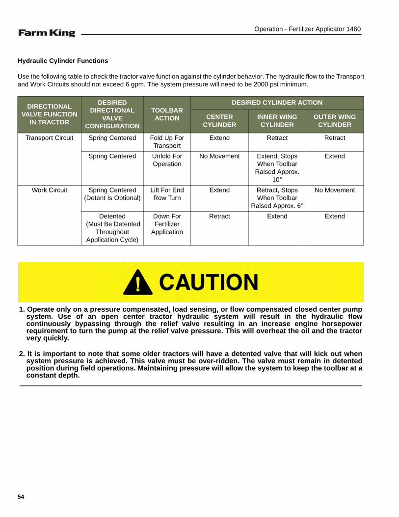
Hydraulic Cylinder Functions
Use the following table to check the tractor valve function against the cylinder behavior. The hydraulic flow to the Transportand Work Circuits should not exceed 6 gpm. The system pressure will need to be 2000 psi minimum.
DIRECTIONAL VALVE FUNCTION
IN TRACTOR
DESIRED DIRECTIONAL
VALVE CONFIGURATION
TOOLBAR ACTION
DESIRED CYLINDER ACTION
CENTER CYLINDER
INNER WING CYLINDER
OUTER WING CYLINDER
Transport Circuit Spring Centered Fold Up For Transport
Extend Retract Retract
Spring Centered Unfold For Operation
No Movement Extend, Stops When Toolbar
Raised Approx. 10°
Extend
Work Circuit Spring Centered (Detent Is Optional)
Lift For End Row Turn
Extend Retract, Stops When Toolbar
Raised Approx. 6°
No Movement
Detented (Must Be Detented
Throughout Application Cycle)
Down For Fertilizer
Application
Retract Extend Extend
1. Operate only on a pressure compensated, load sensing, or flow compensated closed center pumpsystem. Use of an open center tractor hydraulic system will result in the hydraulic flowcontinuously bypassing through the relief valve resulting in an increase engine horsepowerrequirement to turn the pump at the relief valve pressure. This will overheat the oil and the tractorvery quickly.
2. It is important to note that some older tractors will have a detented valve that will kick out whensystem pressure is achieved. This valve must be over-ridden. The valve must remain in detentedposition during field operations. Maintaining pressure will allow the system to keep the toolbar at aconstant depth.
54

Operation - Fertilizer Applicator 1460
Centrifugal Pump (Option)
The pump must always run in a “flooded” condition.Operating the pump in a “non-flooded” condition willcause severe seal damage and possible pump damage.
A “flooded” condition is when the centrifugal pump iscompletely full of fluid and no pockets of air are present inthe pump.
To verify that the pump is flooded, visually check thepump vent line for fluid. Fluid will appear in the vent linewhen pump is flooded.
In order to get maximum pump efficiency, the mountingand plumbing must meet the following guidelines:
Figure 33
The pump inlet must be mounted below the product tanksump to allow gravity to naturally fill the pump with liquid[Figure 33].
The suction line must have a continual rise from thepump inlet to the tank sump [Figure 33].
The pump must have the vent line plumbed to it [Figure33].
Figure 34
An air trap point will occur if the suction line does notgradually rise from the pump inlet [Figure 34].
B-11036
PRODUCT TANK
VENT LINE
PUMP
SUCTION LINE
CORRECT
DO NOT allow an air trap point to occur. Air will beallowed into the pump and may damagecomponents.
B-11037
PRODUCT TANK
VENT LINE
PUMP
SUCTION LINE
WRONG
AIR TRAP(Not Acceptable)
55

Operation - Fertilizer Applicator 1460
Spray Monitor
Figure 35
Cover the monitor daily or when not in use to prevent UVdamage to the equipment [Figure 35].
Cover the monitor daily to prevent damage to theequipment.
B-11039
FLOW TABLE FOR WATER
LEVELGREEN
PLASTIC BALLS
BLACK PLASTIC BALLS
RED PLASTIC BALLS
RED GLASS BALLS
STEEL BALLS
7 0.34 0.47 0.51 0.91 3.33
6 0.24 0.35 0.39 0.71 2.48
5 0.18 0.27 0.28 0.56 1.68
4 0.13 0.20 0.21 0.39 1.09
3 0.08 0.13 0.14 0.27 0.60
2 0.04 0.08 0.08 0.19 0.45
1 0.02 0.03 0.03 0.11 0.30
FLOW TABLE FOR LIQUID FERTILIZER
LEVELRED PLASTIC
BALLSRED GLASS
BALLSSTEEL BALLS
7 0.19 0.84 2.17
6 0.14 0.61 1.70
5 0.12 0.45 1.26
4 0.07 0.32 0.82
3 0.04 0.19 0.58
2 0.02 0.11 0.32
1 0.00 0.05 0.25
56

Operation - Fertilizer Applicator 1460
Filling The Product Tank
Park the tractor / equipment on a flat level surface.
Place all controls in neutral, engage the park brake, stopthe engine and wait for all moving parts to stop. Leavethe operator’s position. (See “Entering And Leaving TheOperator’s Position” on page 45.)
CHEMICAL HAZARD
To prevent serious injury or death:
WEAR PERSONAL PROTECTIVE EQUIPMENT
• Do not allow chemical or solution to touch skin.Some chemicals can be absorbed through theskin.
• Wear rubber gloves and protective gear at alltimes.
DON’T BREATHE VAPOR
• Avoid chemical splash and vapor. Keep othersaway.
• Do not breathe vapor.
• Wear proper respirator when working withchemicals.
• Chemicals can be toxic.
DON’T INGEST CHEMICAL
• If in eyes or mouth, read manufacturer’sinstructions and follow them exactly.
• Seek immediate medical attention.
• A poison control number is usually inside thefront cover of your telephone book.
Do not spill chemicals on skin or clothing. Ifchemicals are spilled, remove contaminatedclothing immediately and wash skin (and clothing)thoroughly with soap and water. Wash hands andface with soap and water and change clothing afterspraying.
Always read the label before using chemicals.Follow the instructions from the chemicalmanufacturer on how to select, use and handle eachchemical. Note protection information each timebefore opening the container.
Add chemical solution to the product tankaccording to the manufacturer’s recommendations.
Some items have been partially disassembled and/or removed to prevent damage to the tank, pump,and other components caused by freezingtemperatures. Please install/assemble prior to firstuse.
57
Operation - Fertilizer Applicator 1460
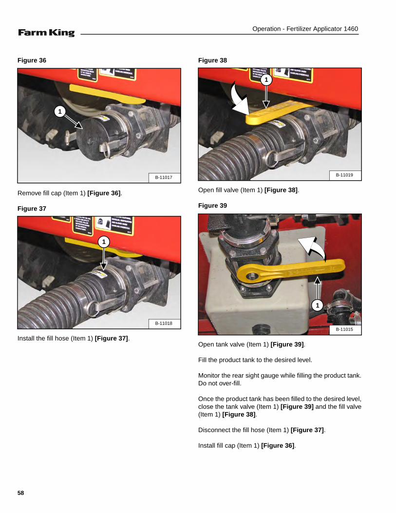
Figure 36
Remove fill cap (Item 1) [Figure 36].
Figure 37
Install the fill hose (Item 1) [Figure 37].
Figure 38
Open fill valve (Item 1) [Figure 38].
Figure 39
Open tank valve (Item 1) [Figure 39].
Fill the product tank to the desired level.
Monitor the rear sight gauge while filling the product tank.Do not over-fill.
Once the product tank has been filled to the desired level,close the tank valve (Item 1) [Figure 39] and the fill valve(Item 1) [Figure 38].
Disconnect the fill hose (Item 1) [Figure 37].
Install fill cap (Item 1) [Figure 36].
B-11017
1
B-11018
1
B-11019
1
B-11015
1
58

Operation - Fertilizer Applicator 1460
Filling Fresh Water Tank
Figure 40
Remove fill cap (Item 1) [Figure 40].
Fill fresh water tank with clean fresh water daily (Do notallow tank to run low on fresh water). Install fill cap.
NOTE: Use water from fresh water tank to clean,rinse or wash anything that has becomecontaminated.
FIELD OPERATION
Pre-Operation
Move the tractor and fertilizer applicator to a level area inthe field. (See “TRANSPORTING” on page 64.)
Engage the tractor hydraulics. (See the tractor’soperator’s manual for the correct procedure.)
Unfold and fully extend the wings. (See “Unfold Wings”on page 52.)
Move the tractor and fertilizer applicator forward and fullylower the toolbar. (See “Raising And Lowering TheToolbar” on page 53.)
Place all controls in neutral, engage the park brake, stopthe engine and wait for all moving parts to stop. Leavethe operator’s position.
Verify that the coulters, injectors or knives areapproximately 2” to 3” below the soil surface.
Adjust coulters as needed to obtain the desired depth.(See “Setting The Toolbar / Coulter Depth” on page 53.)
Adjust wing down-load as needed to maintain the desireddepth. (See “ADJUSTING HYDRAULIC PRESSURE” onpage 72.)
Always use clean, fresh water when filling the freshwater tank.
B-11009
1
Always have the tractor moving forward at aminimum of 3 mph or more when lowering thetoolbar to prevent damage to the coulters.
59

Operation - Fertilizer Applicator 1460
Spray System Test - Ace Centrifugal Pump (Option)
Dry Test
Figure 41
Enter the operator’s position and turn the tractor ignitionswitch to the “ON” position (Do Not start engine.)
Turn the spray controller “ON”.
Press wing section switches on the controller, one at atime and operate each of the manifold valves (Item 1)[Figure 41].
Verify that each manifold valve fully opens and closes.Also verify that the correct switch on the controller isoperating the correct section manifold valve.
Wet Test
Add approximately 300 gallons of clean water to theproduct tank. (See “Filling The Product Tank” onpage 57.)
Inspect the system for leaks. Repair as needed beforeoperating fertilizer applicator.
Verify that there is liquid in the pump vent line.
NOTE: Maximum hydraulic flow for the pump is 11gpm. Start with 5 gpm hydraulic flow andincrease / decrease as needed.
Enter the operator’s position, start the engine.
Engage the tractor hydraulics. (See the tractor’soperator’s manual for the correct procedure.)
Turn the spray controller “ON”.
Place the spray controller in “TEST” mode.
Turn all wing section switches “ON”.
Verify that the pump is flooded and vent line is filled withfluid.
Engage product pump hydraulic circuit (White markers)and place into “detent” position. (See the tractor’soperator’s manual for the correct procedure.)
Operate the product pump for one minute to flush debrisfrom supply lines (If required). Turn off the pump bymoving the hydraulic control to the “float” position.
Determine targeted GPM flow rate.
Select and install properly sized orifices / tips. Perform a“nozzle output check test” to verify application rate.
Inspect spray system components for leaks, loose fittingsand possible pinch points. Tighten loose fittings.
Drain system and clean the line strainer screen.
NOTE: Cover spray monitors daily to preventdamage to components.
Review the spray controller operator’s manual andbe familiar with spray controller calibration andoperation before starting.
B-11022
1
The pump must be filled with liquid during operationto cool the seals. Without liquid to cool the seals,pump failure will occur immediately.
60

Operation - Fertilizer Applicator 1460
John Blue Twin Piston Pump Test (Option)
Ground Wheel Drive Arrangement
Figure 42
Measure the loaded radius from the center of the hub tothe bottom of the tire where it rests on the ground [Figure42].
Press Wheel Drive Arrangement
Measure the loaded radius from the center of the presswheel shaft to where the wheel rests against the tire.
NOTE: The press wheel must be engaged for normaloperation to give an accurate reading.
Swath Width
Figure 43
To determine the swath width, count the number ofoutlets and multiply by the distance (inches) between anytwo outlets, nozzles, or shanks. This assumes that alloutlets are equally spaced. If the outlets are not evenlyspaced, figure the entire length of the boom or toolbarfrom end nozzle to end nozzle and allow for coveragebeyond the ends (Item 1) [Figure 43].
Example: an 11 row boom at 30 inch spacing, wouldhave a swath width of 330 inches.
The measurement for the loaded radius must befrom the Manufacturer of the tire or be measuredunder loaded conditions. The loaded radius tire isalways the tire that has the first drive sprocketattached to its hub.
B-11055
SWATH WIDTH
1
61

Operation - Fertilizer Applicator 1460
Setting The Pump
Read the desired pump setting from the bottom scale onthe pump setting chart.
Loosen the setting pointer nut and rotate the setting hubuntil the setting pointer is over the desired setting.Tighten the setting pointer nut.
Example: An applicator is equipped with a NGP-6050series pump, 11L x 15” tires, a 60 tooth drive sprocket,and a 16 tooth pump driven sprocket. It is desired toapply 33 gallons per acre on a 360 inch swath.
The following steps will determine correct pump setting:
Figure 44
1. Set loaded radius of tire (13.5”) under the sprocketcombination of 16 to 60 in the top window (Item 1)[Figure 44].
2. Set the swath width (360”) under the diamond in themiddle window (Item 2) [Figure 44].
3. Read that the pump setting is approximately 9 at 33gallons per acre on the NGP-6055 scale in the bottomwindow (Item 1) [Figure 44].
4. Set the pump to setting 9 to achieve 33 gallons peracre.
NOTE: The maximum ground speed is read above thediamond as approximately 9 mph to avoidexceeding 450 rpm.
B-11057
1
2
3
62

Operation - Fertilizer Applicator 1460
Operating The Fertilizer Applicator In The Field
Enter the operator’s position, start the engine andrelease the parking brake.
Engage the tractor hydraulics. (See the tractor’soperator’s manual for the correct procedure.)
Fully raise the toolbar.
Move the tractor and fertilizer applicator to the startingarea in the field.
Align the tractor and fertilizer applicator with field / rows.
Drive the tractor and fertilizer applicator forward, towardsthe starting point.
NOTE: When lowering the toolbar in the field, thewings will come down first then the centersection (Normal operation).
As the front tires of the tractor make contact with the field/ rows (starting point), fully lower the toolbar by placingthe “Work Circuit” switch directly into detent.
NOTE: Placing the “Work Circuit” switch into detentwill maintain constant down pressure duringthe application process.
Engage the product pump and turn on the sectionalcontrol valves using the spray controller to startapplication process.
As the tractor approaches the end of the field / rows, turnthe sectional control valves “Off” and fully raise thetoolbar.
Align the tractor and fertilizer applicator with nextapplication area.
As the front tires of the tractor make contact with the field/ rows (next application area), fully lower the toolbar andplace the “Work Circuit” switch into detent.
Continue the application process until the desired area /field is complete.
Stop the tractor and fertilizer applicator on a level surfacein the field.
Place all controls in neutral, engage the park brake, stopthe engine and wait for all moving parts to stop. Leavethe operator’s position.
Clean the product tank. (See “Cleaning The ProductTank” on page 77.)
Place the toolbar and wings in the transport position.(See “TRANSPORTING” on page 64.)
Always have the tractor moving forward at aminimum of 3 mph or more when lowering thetoolbar to prevent damage to the coulters.
PREVENT COULTER DAMAGE
Always fully raise the toolbar before turning thetractor and fertilizer applicator and when moving thetractor and fertilizer applicator to starting point inthe field.
Always flush product tank and system with freshwater before leaving the application area / field.
63

Operation - Fertilizer Applicator 1460
TRANSPORTING
Requirements
Always comply with federal, state, local and provinciallaws regarding the transport of farm equipment on pubicroadways.
Verify that the tractor / tow vehicle is approved fortransporting the equipment and that the equipment issecurely attached to the tractor / tow vehicle.
Verify safety chain is installed and properly connectedbefore transporting equipment.
Verify 7 pin electrical harness is connected and safetylights are working properly.
Verify that the SMV (Slow Moving Vehicle) emblem, alllights and reflectors are clean and visible.
Enter the operator’s position, start the engine andrelease the parking brake.
Engage the tractor hydraulics. (See the tractor’soperator’s manual for the correct procedure.)
Fully raise the toolbar into the transport position. (See“Raising And Lowering The Toolbar” on page 53.)
Fold wings. (See “Unfold Wings” on page 52.)
The ratio of the tractor / tow vehicle weight to the loadedequipment weight plays an important role in definingacceptable travel speed.
TRAVEL SPEED - Acceptable travel speed.
WEIGHT RATIO - Weight of fully equipped or loadedimplement(s) relative to weight of tractor / tow vehicle.
Never exceed 20 mph (32 kph).
Use of an unapproved hitch or tractor / tow vehiclecan result in loss of control, leading to seriousinjury or death.
Tractor / tow vehicle and hitch must have the ratedcapacity to tow equipment.
TRAVEL SPEED WEIGHT RATIO
Up to 20 mph (32 kph) 1 to 1 (or less)
Up to 10 mph (16 kph) 2 to 1 (or less)
DO NOT TOW More than 2 to 1
Never attempt to fold / unfold the wings unless thetoolbar is in the FULLY RAISED FIELD position.Failure to comply may result in severe equipmentdamage.
AVOID SERIOUS INJURY OR DEATH
DO NOT transport a loaded fertilizer applicator onpublic roadways. Excess weight will greatlyincrease tractor stopping distance and may causethe operator to lose control of the tractor or towvehicle.
64

Maintenance - Fertilizer Applicator 1460
MAINTENANCE
TROUBLESHOOTING . . . . . . . . . . . . . . . . . . . . . . . . . . . . . . . . . . . . . . . . . . . . . . . . . . . . . . . . . . . 67Chart . . . . . . . . . . . . . . . . . . . . . . . . . . . . . . . . . . . . . . . . . . . . . . . . . . . . . . . . . . . . . . . . . . . . . . 67
SERVICE SCHEDULE . . . . . . . . . . . . . . . . . . . . . . . . . . . . . . . . . . . . . . . . . . . . . . . . . . . . . . . . . . . 69Maintenance Intervals . . . . . . . . . . . . . . . . . . . . . . . . . . . . . . . . . . . . . . . . . . . . . . . . . . . . . . . . . 69
LUBRICATION . . . . . . . . . . . . . . . . . . . . . . . . . . . . . . . . . . . . . . . . . . . . . . . . . . . . . . . . . . . . . . . . . 70Recommendations . . . . . . . . . . . . . . . . . . . . . . . . . . . . . . . . . . . . . . . . . . . . . . . . . . . . . . . . . . . 70Locations . . . . . . . . . . . . . . . . . . . . . . . . . . . . . . . . . . . . . . . . . . . . . . . . . . . . . . . . . . . . . . . . . . . 70
ADJUSTING HYDRAULIC PRESSURE . . . . . . . . . . . . . . . . . . . . . . . . . . . . . . . . . . . . . . . . . . . . . .72Procedure . . . . . . . . . . . . . . . . . . . . . . . . . . . . . . . . . . . . . . . . . . . . . . . . . . . . . . . . . . . . . . . . . . 72Dealer / Grower Supplied Coulters Procedure . . . . . . . . . . . . . . . . . . . . . . . . . . . . . . . . . . . . . . 74
AXLES . . . . . . . . . . . . . . . . . . . . . . . . . . . . . . . . . . . . . . . . . . . . . . . . . . . . . . . . . . . . . . . . . . . . . . . 75Wheel Nut Torque . . . . . . . . . . . . . . . . . . . . . . . . . . . . . . . . . . . . . . . . . . . . . . . . . . . . . . . . . . . .75Tire / Wheel Replacement . . . . . . . . . . . . . . . . . . . . . . . . . . . . . . . . . . . . . . . . . . . . . . . . . . . . . 75Tire Pressure . . . . . . . . . . . . . . . . . . . . . . . . . . . . . . . . . . . . . . . . . . . . . . . . . . . . . . . . . . . . . . .76
CLEANING . . . . . . . . . . . . . . . . . . . . . . . . . . . . . . . . . . . . . . . . . . . . . . . . . . . . . . . . . . . . . . . . . . . . 77Cleaning The Product Tank . . . . . . . . . . . . . . . . . . . . . . . . . . . . . . . . . . . . . . . . . . . . . . . . . . . . .77Cleaning The Line Strainer Screen . . . . . . . . . . . . . . . . . . . . . . . . . . . . . . . . . . . . . . . . . . . . . . . 78Cleaning The Fertilizer Applicator . . . . . . . . . . . . . . . . . . . . . . . . . . . . . . . . . . . . . . . . . . . . . . . . 78
SAFETY SIGN (DECAL) INSTALLATION . . . . . . . . . . . . . . . . . . . . . . . . . . . . . . . . . . . . . . . . . . . . 78Procedure . . . . . . . . . . . . . . . . . . . . . . . . . . . . . . . . . . . . . . . . . . . . . . . . . . . . . . . . . . . . . . . . . . 78
STORAGE AND RETURN TO SERVICE . . . . . . . . . . . . . . . . . . . . . . . . . . . . . . . . . . . . . . . . . . . . . 79Storage . . . . . . . . . . . . . . . . . . . . . . . . . . . . . . . . . . . . . . . . . . . . . . . . . . . . . . . . . . . . . . . . . . . . 79Return To Service . . . . . . . . . . . . . . . . . . . . . . . . . . . . . . . . . . . . . . . . . . . . . . . . . . . . . . . . . . . .79
65

Maintenance - Fertilizer Applicator 1460
66
Maintenance - Fertilizer Applicator 1460
TROUBLESHOOTING
Chart
NOTE: If a problem is encountered that is difficult to solve, even after having read through this troubleshootingsection, please call your local Farm King dealer. Before you call, please have this Operator And PartsManual and the serial number of your machine at hand.
PROBLEM CAUSE CORRECTION
Coulters float out of the ground duringfield operation.
Tractor hydraulic valve is not placedinto detent.
Make sure that the Work Circuit is indetent during the entire work cycle.
Reducing / relieving valve pressure isnot set high enough for soil conditions.
Adjust the valve pressure up by 100 psiincrements until gauge wheels maintainconstant contact with the ground.
Outer wings drift back during fieldoperation.
Tractor hydraulic valve is not placedinto detent.
Make sure that the Work Circuit is indetent during the field operation.
Wings do not raise or lower evenly. Flow divider is not functioning properly. Check, replace if necessary.
When the wings are horizontal andthe directional valves are not beingused, the wings drift oppositely, oneup, one down.
The pilot operated check valves are notoperating properly.
Check, replace if necessary.
During the initial unfold with wingscompletely folded, the outer wingcylinders begin to extend immediately.
Tractor's hydraulic flow is set too high. Reduce tractor’s flow until wings foldproperly, 4 to 6 GPM.
Sequence valve enabling pressure isset too low.
Adjust the valve pressure by 1/2 turns(180°) clockwise until outer wingsremain fixed during the initial unfoldstage.
During transport unfold, toolbar doesnot stop before toolbar wings achievethe unfolded, level position.
No power to microswitch, solenoidvalve (2) is not enabled.
Check to make sure all electricalconnections are good.
Microswitch is improperly adjusted. Adjust microswitch position to enablesolenoid valves at the correct height.
Solenoid valve (2) is not functioningproperly.
Check, replace if necessary.
Instructions are necessary before operating or servicing equipment. Read and understand theOperator And Parts Manual and safety signs (decals) on equipment. Follow warnings andinstructions in the manuals when making repairs, adjustments or servicing. Check for correctfunction after adjustments, repairs or service. Untrained operators and failure to follow instructionscan cause injury or death.
67

Maintenance - Fertilizer Applicator 1460
During field operation, lifting thetoolbar for end row turns, the wings donot stop slightly above level.
No power to microswitch, solenoidvalve (1) is not enabled.
Check to make sure all electricalconnections are good.
Microswitch is improperly adjusted. Adjust microswitch position to enablesolenoid valves at the correct height.
Solenoid valve (2) is not functioningproperly.
Check, replace if necessary.
When lowering toolbar to fieldoperation position, the center cylinderchatters or does not lower.
Counter balance valve is cycling inrapid succession, insufficient oil flow.
Increase oil flow from tractor SCV.
Counter balance valves out ofadjustment.
Increase the tractor engine rpm toincrease hydraulic oil flow.
Defective counter balance valve. Replace valve.
Outer coulters run, too deep or centersection runs too shallow. The toolbardoes not seem to be parallel to thesoil profile.
Improper depth settings. Change depth control stops on thecenter cylinders.
Reset wing gauge wheel height.
During transport unfold, toolbar doesnot move from folded position.
Reducing/relieving valve pressure setbeneath pressure needed to extendmid-wing.
Increase valve setting by turning setscrew clockwise by quarter turns untiltoolbar unfolds.
During transport unfold, toolbarchatters and / or bounces.
Tractor oil flow through transport cicuitvalve is set too high.
Reduce tractor flow rate until chatter orbounce stops, 4 to 6 GPM
PROBLEM CAUSE CORRECTION
68

Maintenance - Fertilizer Applicator 1460
SERVICE SCHEDULE
Maintenance Intervals
Maintenance work must be done at regular intervals. Failure to do so will result in excessive wear and early failures.The service schedule is a guide for correct maintenance of the fertilizer applicator.
# DESCRIPTIONSERVICE PROCEDURES
Winterize Clean Lube Change Cover Drain Locations
Daily Maintenance (or every 8 hours)
1 Fresh Water Tank • •
2 Coulter Lower Parallel Arm •
3 Coulter Pivots •
4 Spray Monitor •
Weekly (or every 50 hours)
4 Line Strainer Screen •
5 Inner Wing Fold Bushings •
5 Outer Wing Fold Bushings •
Every 250 hours
6 Wheel Bearings (Running gear and gauge wheels)
•
7 Coulter Hub Bearings •
Annually (or every 500 hours)
8 Product Tank •
9 Machine • •
10 Spray Monitor • • •
Instructions are necessary before operating or servicing equipment. Read and understand theOperator and Parts Manual and safety signs (decals) on equipment. Follow warnings and instructionsin the manuals when making repairs, adjustments or servicing. Check for correct function afteradjustments, repairs or service. Untrained operators and failure to follow instructions can causeinjury or death.
69

Maintenance - Fertilizer Applicator 1460
LUBRICATION
Recommendations
Always use a good quality multi-purpose / lithium basegrease when lubricating the equipment.
• Always use a hand-held grease gun.
• Clean fitting before greasing, to avoid injecting dirtand grit.
• Replace and repair broken fittings immediately.
• If fittings will not take grease, remove and cleanthoroughly. Replace fitting if necessary.
Locations
Lubricate the following grease locations EVERY 8HOURS:
Figure 45
Apply two pumps of grease to the coulter lower parallelarm (Item 1) [Figure 45].
Figure 46
Apply two pumps of grease to the coulter pivots (Item 1)and to the pressed hub assembly (Item 2) [Figure 46].
Do not over-grease bearings. Greasing too often candamage seals and lead to premature bearing failure.
Only sealed bushings are used on the applicator. Donot over-grease.
Fluid such as engine oil, hydraulic fluid, coolants,grease, etc. must be disposed of in anenvironmentally safe manner. Some regulationsrequire that certain spills and leaks on the groundmust be cleaned in a specific manner. See local,state and federal regulations for the correctdisposal.
B-0166
1
2
B-0165
1
2
2
70
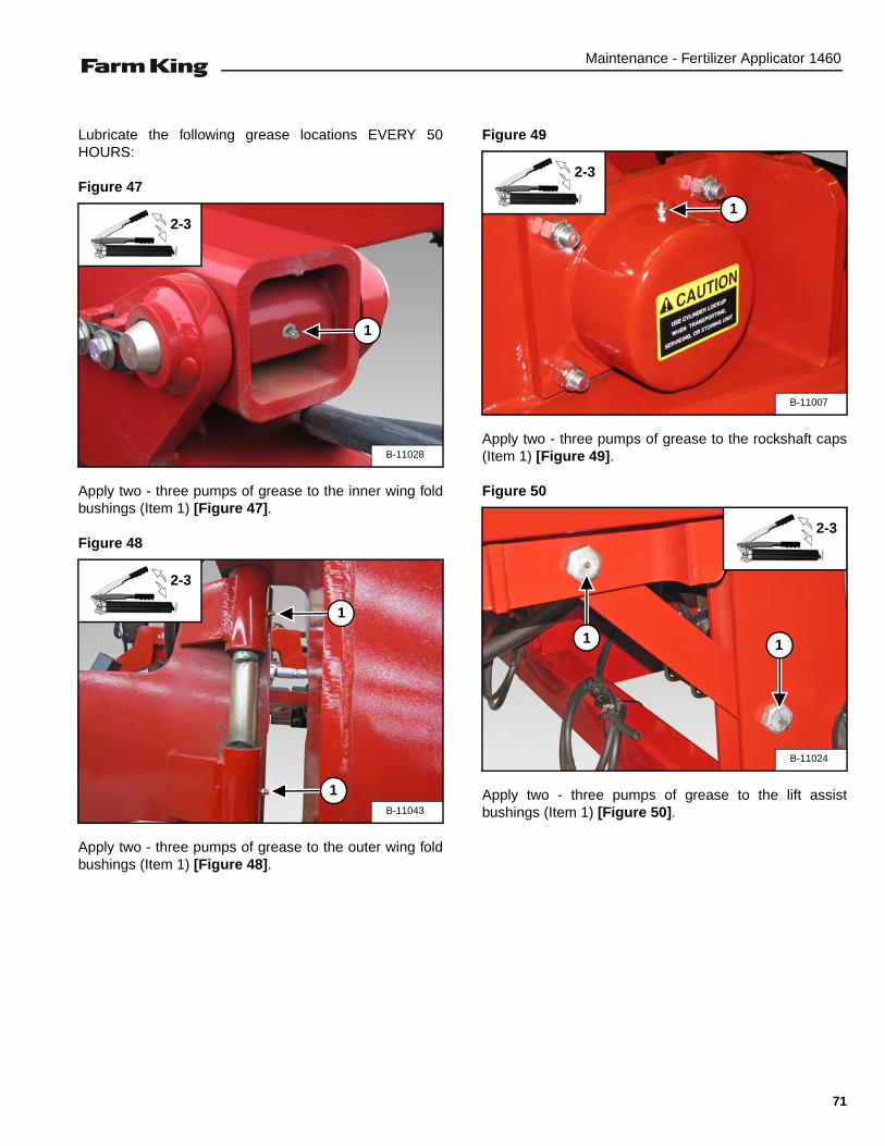
Maintenance - Fertilizer Applicator 1460
Lubricate the following grease locations EVERY 50HOURS:
Figure 47
Apply two - three pumps of grease to the inner wing foldbushings (Item 1) [Figure 47].
Figure 48
Apply two - three pumps of grease to the outer wing foldbushings (Item 1) [Figure 48].
Figure 49
Apply two - three pumps of grease to the rockshaft caps(Item 1) [Figure 49].
Figure 50
Apply two - three pumps of grease to the lift assistbushings (Item 1) [Figure 50].
B-11028
2-3
1
B-11043
2-3
1
1
B-11007
2-3
1
B-11024
2-3
11
71

Maintenance - Fertilizer Applicator 1460
Lubricate the following grease locations EVERY 250HOURS:
Figure 51
Apply two pumps of grease to the gauge wheel hubs(Item 1) [Figure 51].
Figure 52
Apply two - three pumps of grease to the running wheelbearings (Item 1) [Figure 52].
ADJUSTING HYDRAULIC PRESSURE
Procedure
NOTE: The pressure reducing valve (PR1) controlsthe amount of downward pressure applied tothe outer coulters. The adjustment range isfrom 800 to 1,500 PSI. The factory setting is800 to 1,100 PSI, which is adequate for mostconditions.
Move the tractor and fertilizer applicator to a soft levelarea.
Engage the parking brake, relieve hydraulic pressure,turn engine off and leave the operator’s position. (See“Entering And Leaving The Operator’s Position” onpage 45.)
B-0185
1
2
B-11012
1
2-3
DOWN PRESSURE ON OUTER COULTERS
• Too much down pressure will put unnecessarystress on the machine and will put more load onthe gauge wheels.
• Too little pressure may not keep the coulters inthe ground at the proper depth.
Always check with a pressure gauge while the SCVcontrol lever is left in the detented position. DO NOTadjust the pressure without a pressure gauge.
DO NOT MAKE HYDRAULIC PRESSUREADJUSTMENTS ON HARD / PAVED SURFACE.
72

Maintenance - Fertilizer Applicator 1460
Figure 53
Install a 3000 PSI gauge (Item 1) in gauge port 15 (Item 2) [Figure 53] of the hydraulic block.
NOTE: This plug is ORB, use the correct fitting when installing the 3000 PSI gauge.
Verify that all hydraulic hoses and electrical harnesses are connected to the tractor.
Enter the tractor, start the engine and engage the tractor’s auxiliary hydraulics.
Unfold wings and lower the toolbar to the ground.
Lock or place the SCV control lever in detent (Work Circuit). Run engine at operating speed.
Leave the operator’s position.
Using a 3/4” (19 mm) wrench, loosen the lock nut on the pressure reducing valve (Item 3) [Figure 53].
While watching the 3000 PSI gauge,
• Turn the set screw clockwise to increase pressure or turn set screw counter-clockwise to decrease pressure until thedesired pressure is achieved
Tighten lock nut on the pressure reducing valve.
Enter the operator’s position, release parking brake, raise the toolbar and move the tractor and fertilizer applicator to thefield (work area). Test the fertilizer applicator in the field (work area).
NOTE: If further adjustment is required, repeat the above procedure until the desired pressure is achieved.
88668043
1
3
2
73

Maintenance - Fertilizer Applicator 1460
Dealer / Grower Supplied Coulters Procedure
Figure 54
Follow these steps to adjust the counter balance valves:
1. Begin with the fertilizer applicator in the fully folded, transport position.
NOTE: Verify that all cylinder stops are in place before continuing to step 2.
2. Adjust counterbalance valve 3 (CB3) (Item 1) [Figure 54]. Turn adjustment screw all the way in (clockwise). Afteradjustment screw is turned all the way in, back the adjustment screw out 1-1/4 turns (counterclockwise).
3. Adjust counterbalance valves 1 & 2 (CB1 & CB2) (Items 2 & 3) [Figure 54]. Turn adjustment screw out(counterclockwise) so that there are 9 to 10 threads showing above the jam nut on the valve when the jam nut istightened.
4. Remove all stops.
5. Using the Transport Circuit, unfold the fertilizer applicator.
6. For further adjustments (See “TROUBLESHOOTING” on page 67.)
Delivery of the fertilizer applicator without factory supplied coulters may require additional adjustment of thehydraulic system to accommodate the weight of the coulters used. This unknown weight directly affects thehydraulic pressures in the folding / unfolding and raising / lowering of the toolbar.
Folding and unfolding of the fertilizer applicator toolbar functions are controlled hydraulically bycontrol valves that rely on pressure to open and close. The different hydraulic pressures in thecylinders may cause the folding and unfolding functions of the fertilizer applicator toolbar to notfunction correctly.
B-11044
1
2
3
74

Maintenance - Fertilizer Applicator 1460
AXLES
Wheel Nut Torque
Tighten wheel nuts to 420 ft.-lb. (567 N•m) torque.
Tire / Wheel Replacement
Periodically check tires for cuts, bulges and damagedrims.
Park the tractor / equipment on a flat level surface.
Place all controls in neutral, engage the park brake, stopthe engine and wait for all moving parts to stop. Leavethe operator’s position.
Fully raise wings into transport position and secure.
Place chock blocks behind and in front of the oppositetire to be removed.
Raise axle frame with jack until the tire / wheel is slightlyoff the ground.
NOTE: Place blocks / stands under the frame tosecure the fertilizer applicator when tire /wheel is raised off the ground.
Remove the ten wheel nuts and tire assembly.
Figure 55
Install the new tire with the valve stem facing out.
Reinstall ten wheel nuts (Items 1 - 10) [Figure 55].
Tighten wheel nuts in a criss-cross pattern [Figure 55].Tighten wheel nuts to 420 ft.-lb. (567 N•m) of torque.
Lower tire / wheel assembly to the ground.
After tightening the wheel nuts, pull the fertilizerapplicator approximately one (1) mile and re-tighten thewheel nuts to 420 ft.-lb. (567 N•m) of torque.
CHECK WHEEL NUTS AFTER:1. First 3 (three) hours of field operation.
2. First 10 (ten) hours of field operation.
3. First 50 (fifty) hours of field operation.
4. Every 200 (two hundred) hours of operation.
REPEAT PROCEDURE IF A WHEEL IS REMOVED OR REINSTALLED
AVOID INJURY OR DEATH
Before you leave the operator’s position:
• Always park on a flat level surface.• Place all controls in NEUTRAL.• Engage the park brake.• Stop the engine and remove the key.• Wait for all moving parts to stop.
AVOID INJURY OR DEATH
• Always chock tires before performing anymaintenance or service.
B-11012
2
6
4
1
3
7
8
5
9
10
75

Maintenance - Fertilizer Applicator 1460
Tire Pressure
Check tire pressure daily. Fill tires per tire manufacturer'srecommendation. See side wall of tire for inflationrequirements.
When inflating tires, use a clip-on chuck andextension hose long enough to allow you to stand toone side and NOT in front of or over the tireassembly.
76

Maintenance - Fertilizer Applicator 1460
CLEANING
Cleaning The Product Tank
Fill product tank approximately half full, with clean water.(See “Filling The Product Tank” on page 57.)
Engage product pump and flush out through the nozzles.
Add a proper cleaning agent and fill product tankapproximately half full one more time.
Engage product pump and flush out through the nozzles.
Fill product tank approximately half full, with clean water,engage product pump and flush out through the nozzlesfor the final rinse.
CHEMICAL HAZARD
To prevent serious injury or death:
WEAR PERSONAL PROTECTIVE EQUIPMENT
• Do not allow chemical or solution to touch skin.Some chemicals can be absorbed through theskin.
• Wear rubber gloves and protective gear at alltimes.
DON’T BREATHE VAPOR
• Avoid chemical splash and vapor. Keep othersaway.
• Do not breathe vapor.
• Wear proper respirator when working withchemicals.
• Chemicals can be toxic.
DON’T INGEST CHEMICAL
• If in eyes or mouth, read manufacturer’sinstructions and follow them exactly.
• Seek immediate medical attention.
• A poison control number is usually inside thefront cover of your telephone book.
The tank and system must be emptied of chemicalmixture and flushed with clean water beforeservicing the spray system or sprayingcomponents.
Do not spill chemicals on skin or clothing. Ifchemicals are spilled, remove contaminatedclothing immediately and wash skin (and clothing)thoroughly with soap and water. Wash hands andface with soap and water and change clothing afterspraying.
Rinse and clean any exterior surfaces andcomponents immediately if any liquid fertilizer spillsor leaks occur.
77

Maintenance - Fertilizer Applicator 1460
Cleaning The Line Strainer Screen
Clean the line strainer screen every 50 hours ofoperation.
Figure 56
Loosen and remove the line strainer canister (Item 1)[Figure 56] by hand (do not use a wrench).
Remove screen (Item 2) [Figure 56] and clean from theinside with clean water.
Inspect the screen for holes or tears. If the screen isdamaged, replace the screen.
Install screen and line strainer canister. Hand tighten theline strainer canister (do not use a wrench).
Cleaning The Fertilizer Applicator
Clean and rinse all exterior surfaces and componentswith clean water and cleaning agent to prevent corrosion.
SAFETY SIGN (DECAL) INSTALLATION
Procedure
• Remove all portions of the damaged safety sign(decal).
• Thoroughly clean the area with adhesive remover andglass cleaner. Remove all adhesive residue.
• Allow the area to dry completely before installing thenew safety sign (decal).
• Position the safety sign (decal) in the correct location.Remove a small portion of the backing paper on thesafety sign (decal).
• Press on the safety sign (decal) where the backingpaper has been removed.
• Slowly remove the remaining backing paper, pressingon the safety sign (decal) as the backing paper isremoved.
• Using the backing paper, pressing firmly, move thebacking paper over the entire safety sign (decal) area.
NOTE: Small air pockets can be pierced with a pinand smoothed out using the piece of thebacking paper.
The tank and system must be emptied of chemicalmixture and flushed with clean water beforeservicing the spray system or sprayingcomponents.
B-11020
1
2
When replacing safety signs (decals), thetemperature must be above 10° C (50° F).
78

Maintenance - Fertilizer Applicator 1460
STORAGE AND RETURN TO SERVICE
Storage
Sometimes it may be necessary to store your Farm Kingfertilizer applicator for an extended period of time. Belowis a list of items to perform before storage.
• Add 20 gal (75 liters) of clean water to the fertilizertank and flush out toolbar / wings. Repeat three times.
• Thoroughly wash the machine with a pressure washeror water hose to remove all dirt, mud, debris orresidue.
• Remove knives, injectors and orifices from the coulterassembly. Wash thoroughly. Apply a thin layer ofgrease to coulter blades/knives and exposed cylindershafts to prevent rust.
• Winterize with RV antifreeze.
• Lubricate all bushings to remove any water residuefrom washing.
• Remove any material that has become entangledaround any moving part.
• Raise and fold the toolbar and wings into their fully upand retracted configuration.
• Clean, flush, drain and cover spray monitors toprotect from UV exposure.
• Place hydraulic hoses and 7-pin connector in thestorage brackets.
• Inspect the hitch and all welds on the equipment forwear and damage.
• Check for loose hardware, missing guards, ordamaged parts.
• Check for damaged or missing safety signs (decals).Replace if necessary.
• Replace worn or damaged parts.
• Touch up all paint nicks and scratches to preventrusting.
• Place the equipment in a dry protected shelter.
NOTE: If a dry protected shelter is not available,cover with a waterproof tarp and tie downsecurely.
• Place the equipment flat on the ground.
• Support the jack / frame with planks if required.
Return To Service
After the Farm King fertilizer applicator has been instorage, it is necessary to follow a list of items to returnthe equipment to service.
• Be sure all shields and guards are in place.
• Lubricate the equipment.
• Connect to a tractor and operate equipment, verify allfunctions operate correctly.
• Check for leaks. Repair as needed.
DO NOT permit children to play on or around thestored machine.
79

Maintenance - Fertilizer Applicator 1460
80

Parts Identification - Fertilizer Applicator 1460
PARTS IDENTIFICATION
GENERAL PARTS INFORMATION . . . . . . . . . . . . . . . . . . . . . . . . . . . . . . . . . . . . . . . . . . . . . . . . .83
ADJUSTABLE AXLE . . . . . . . . . . . . . . . . . . . . . . . . . . . . . . . . . . . . . . . . . . . . . . . . . . . . . . . . . . . . 83
PINTLE HITCH ASSEMBLY . . . . . . . . . . . . . . . . . . . . . . . . . . . . . . . . . . . . . . . . . . . . . . . . . . . . . . . 84
FRAME ASSEMBLY . . . . . . . . . . . . . . . . . . . . . . . . . . . . . . . . . . . . . . . . . . . . . . . . . . . . . . . . . . . . . 86
TOOLBAR ASSEMBLY (431.31 IN.) . . . . . . . . . . . . . . . . . . . . . . . . . . . . . . . . . . . . . . . . . . . . . . . . 88
TOOLBAR ASSEMBLY (491.31 IN.) . . . . . . . . . . . . . . . . . . . . . . . . . . . . . . . . . . . . . . . . . . . . . . . . 90
HYDRAULIC PLUMBING ASSEMBLY (W/O OUTER WINGS) . . . . . . . . . . . . . . . . . . . . . . . . . . . .92
HYDRAULIC PLUMBING ASSEMBLY (W / OUTER WINGS) . . . . . . . . . . . . . . . . . . . . . . . . . . . . . 94
HYDRAULIC MANIFOLD BLOCK (W/O OUTER WINGS) . . . . . . . . . . . . . . . . . . . . . . . . . . . . . . . .96
HYDRAULIC MANIFOLD BLOCK (W / OUTER WINGS) . . . . . . . . . . . . . . . . . . . . . . . . . . . . . . . . 98
TANK AND PLUMBING ASSEMBLY . . . . . . . . . . . . . . . . . . . . . . . . . . . . . . . . . . . . . . . . . . . . . . . 100
HAND RINSE TANK ASSEMBLY . . . . . . . . . . . . . . . . . . . . . . . . . . . . . . . . . . . . . . . . . . . . . . . . . . 102
HAND / EYE RINSE TANK ASSEMBLY . . . . . . . . . . . . . . . . . . . . . . . . . . . . . . . . . . . . . . . . . . . . .103
ACE CENTRIFUGAL PUMP & PLUMBING ASSEMBLY (OPTION) . . . . . . . . . . . . . . . . . . . . . . . 104
TANK QUICK FILL PLUMBING ACE CENTRIFUGAL PLUMBING ASSEMBLY . . . . . . . . . . . . . . 106
JOHN BLUE GROUND DRIVE MOUNT ASSEMBLY . . . . . . . . . . . . . . . . . . . . . . . . . . . . . . . . . .108
JOHN BLUE TWIN PUMP ASSEMBLY . . . . . . . . . . . . . . . . . . . . . . . . . . . . . . . . . . . . . . . . . . . . .110
RAVEN CONTROL PLUMBING ASSEMBLY . . . . . . . . . . . . . . . . . . . . . . . . . . . . . . . . . . . . . . . . . 112
SPRAY MONITORS . . . . . . . . . . . . . . . . . . . . . . . . . . . . . . . . . . . . . . . . . . . . . . . . . . . . . . . . . . . . 114
SINGLE COLUMN MONITOR ASSEMBLY . . . . . . . . . . . . . . . . . . . . . . . . . . . . . . . . . . . . . . . . . . 116
MICROSWITCH . . . . . . . . . . . . . . . . . . . . . . . . . . . . . . . . . . . . . . . . . . . . . . . . . . . . . . . . . . . . . . . 117
COULTER W / KNIFE GROUP . . . . . . . . . . . . . . . . . . . . . . . . . . . . . . . . . . . . . . . . . . . . . . . . . . . 11812 Row - 30” Spacing / 11 Coulters . . . . . . . . . . . . . . . . . . . . . . . . . . . . . . . . . . . . . . . . . . . . . 11812 Row - 36” Spacing / 11 Coulters . . . . . . . . . . . . . . . . . . . . . . . . . . . . . . . . . . . . . . . . . . . . . 11812 Row - 38” Spacing / 11 Coulters . . . . . . . . . . . . . . . . . . . . . . . . . . . . . . . . . . . . . . . . . . . . . 11812 Row - 40” Spacing / 11 Coulters . . . . . . . . . . . . . . . . . . . . . . . . . . . . . . . . . . . . . . . . . . . . . 11816 Row - 22” Spacing / 15 Coulters . . . . . . . . . . . . . . . . . . . . . . . . . . . . . . . . . . . . . . . . . . . . . 11916 Row - 30” Spacing / 17 Coulters . . . . . . . . . . . . . . . . . . . . . . . . . . . . . . . . . . . . . . . . . . . . . 11924 Row - 22” Spacing / 23 Coulters . . . . . . . . . . . . . . . . . . . . . . . . . . . . . . . . . . . . . . . . . . . . . 119
81

Parts Identification - Fertilizer Applicator 1460
COULTER W / INJECTOR GROUP . . . . . . . . . . . . . . . . . . . . . . . . . . . . . . . . . . . . . . . . . . . . . . . .12012 Row - 30” Spacing / 11 Coulters . . . . . . . . . . . . . . . . . . . . . . . . . . . . . . . . . . . . . . . . . . . . .12012 Row - 36” Spacing / 11 Coulters . . . . . . . . . . . . . . . . . . . . . . . . . . . . . . . . . . . . . . . . . . . . .12012 Row - 38” Spacing / 11 Coulters . . . . . . . . . . . . . . . . . . . . . . . . . . . . . . . . . . . . . . . . . . . . .12012 Row - 40” Spacing / 11 Coulters . . . . . . . . . . . . . . . . . . . . . . . . . . . . . . . . . . . . . . . . . . . . .12016 Row - 22” Spacing / 15 Coulters . . . . . . . . . . . . . . . . . . . . . . . . . . . . . . . . . . . . . . . . . . . . .12116 Row - 30” Spacing / 15 Coulters . . . . . . . . . . . . . . . . . . . . . . . . . . . . . . . . . . . . . . . . . . . . .12116 Row - 30” Spacing / 17 Coulters . . . . . . . . . . . . . . . . . . . . . . . . . . . . . . . . . . . . . . . . . . . . .12124 Row - 22” Spacing / 23 Coulters . . . . . . . . . . . . . . . . . . . . . . . . . . . . . . . . . . . . . . . . . . . . .121
COULTER ASSEMBLY (STRAIGHT) . . . . . . . . . . . . . . . . . . . . . . . . . . . . . . . . . . . . . . . . . . . . . . .122RH W / Knife . . . . . . . . . . . . . . . . . . . . . . . . . . . . . . . . . . . . . . . . . . . . . . . . . . . . . . . . . . . . . . .122RH W / Injector . . . . . . . . . . . . . . . . . . . . . . . . . . . . . . . . . . . . . . . . . . . . . . . . . . . . . . . . . . . . .124
COULTER ARM ASSEMBLY . . . . . . . . . . . . . . . . . . . . . . . . . . . . . . . . . . . . . . . . . . . . . . . . . . . . .126RH W / Injector . . . . . . . . . . . . . . . . . . . . . . . . . . . . . . . . . . . . . . . . . . . . . . . . . . . . . . . . . . . . .126
COULTER CLAMP KIT (4X6 BAR) . . . . . . . . . . . . . . . . . . . . . . . . . . . . . . . . . . . . . . . . . . . . . . . .128
COULTER HOSE ASSEMBLY . . . . . . . . . . . . . . . . . . . . . . . . . . . . . . . . . . . . . . . . . . . . . . . . . . . .129
GAUGE WHEEL GROUP LH / RH . . . . . . . . . . . . . . . . . . . . . . . . . . . . . . . . . . . . . . . . . . . . . . . . .130
GAUGE WHEEL HUB ASSEMBLY (256 - 6 - 6 - 4.62) . . . . . . . . . . . . . . . . . . . . . . . . . . . . . . . . .131
LIGHTING MARKING GROUP . . . . . . . . . . . . . . . . . . . . . . . . . . . . . . . . . . . . . . . . . . . . . . . . . . . .132
ELECTRICAL HARNESSES / ROUTING . . . . . . . . . . . . . . . . . . . . . . . . . . . . . . . . . . . . . . . . . . .134
RUNNING GEAR HUB ASSEMBLY (11.25BC, 15000#) . . . . . . . . . . . . . . . . . . . . . . . . . . . . . . . .135
OUTER WING FOLD CYLINDERS . . . . . . . . . . . . . . . . . . . . . . . . . . . . . . . . . . . . . . . . . . . . . . . .136
TOOLBAR LIFT CYLINDERS . . . . . . . . . . . . . . . . . . . . . . . . . . . . . . . . . . . . . . . . . . . . . . . . . . . .138
INNER WING FOLD CYLINDERS . . . . . . . . . . . . . . . . . . . . . . . . . . . . . . . . . . . . . . . . . . . . . . . . .140
RAVEN 450 . . . . . . . . . . . . . . . . . . . . . . . . . . . . . . . . . . . . . . . . . . . . . . . . . . . . . . . . . . . . . . . . . .141
WHEEL PROXIMITY SENSOR ASSEMBLY . . . . . . . . . . . . . . . . . . . . . . . . . . . . . . . . . . . . . . . . .142
GPS SPEED SENSOR ASSEMBLY . . . . . . . . . . . . . . . . . . . . . . . . . . . . . . . . . . . . . . . . . . . . . . .143
82

Parts Identification - Fertilizer Applicator 1460
GENERAL PARTS INFORMATION
The parts identification section list descriptions, part numbers and quantities for all North America Base Model 1460fertilizer applicators. Contact your Farm King dealer for additional fertilizer applicator parts information.
ADJUSTABLE AXLE
ITEM PART NUMBER DESCRIPTION QTY1 09706701 BOLT, CSHH G5 P 0.75” x 2.50” 82 88666423 BOLT, HEX, 1” x 9.50” G8 YZ 43 SX013733 WASHER; 2.50” x 0.5”, 1.047” HOLE 44 SX013949G AXLE INSERT ASSEMBLY, GREEN 2
SX013949R AXLE INSERT ASSEMBLY, RED 25 SX014027G AXLE WELDMENT, GREEN 1
SX014027R AXLE WELDMENT, RED 16 SXLN-075-NI-YZ LOCKNUT, 3/4” NYLON INSERT YZ 87 SXLN-100-NI-YZ LOCKNUT, 1 NYLON INSERT 48 SX018238C LH TIRE / WHEEL ASSEMBLY, 380 CREAM 19 SX018239C RH TIRE / WHEEL ASSEMBLY, 380 CREAM 1
88668129-B
1
FRONT(Direction Of Travel)
5
2
4
6
3
7
8
9
83

Parts Identification - Fertilizer Applicator 1460
PINTLE HITCH ASSEMBLY
88668000
1
86
9
10
13
10
12
11
14
2
3
5
7
4
84

Parts Identification - Fertilizer Applicator 1460
ITEM PART NUMBER DESCRIPTION QTY1 88666482 5 TON JACK WELDMENT, TW 12 88668004 BOLT, 1.00” x 7.00” HEX GR 8 YZ 23 SX014072 TUBE RD, 2.00” OD x 1.020” ID x 0.88 14 SX014119 SAFETY CHAIN, 21000# 15 SX014120 PLATE, 0.50” x 3.25” DIA W/HOLE 16 SX014121 PIGTAIL WELDMENT 17 SXBH1004008YZ BOLT, 1.00” x 4.00” HEX GR 8 YZ 18 SXBHF0311255YZ BOLT’ 5/16” x 1.25” FLG GR 5 YLLX ZN 29 SXLN-031-NIYZ LOCKNUT, 5/16” NYLON INSERT YZ 2
10 SXLN-100-NI-YZ LOCKNUT, 1” NYLON INSERT 311 SXPPI-208VR PINTLE CLEVIS OPTION 112 SXPPI-331VH PINTLE HITCH CASTING 113 SXWB85 BOLT, WB82 CLEVIS OPTION 114 SXWB91 NUT, 3/4”-10 GR 8 CLEVIS, OPTION 1
85
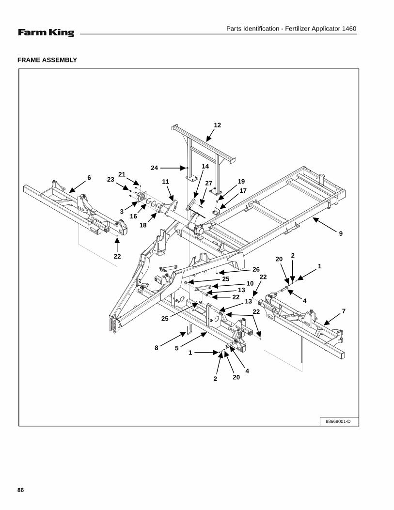
Parts Identification - Fertilizer Applicator 1460
FRAME ASSEMBLY
88668001-D
1
2 204
5
22
13
22
1310
22
25
26
2201
4
725
8
9
22
316
18
2321
11
1424
12
27 1917
6
86

Parts Identification - Fertilizer Applicator 1460
ITEM PART NUMBER DESCRIPTION QTY
1 00012012 BOLT, 0.38” x 0.75” CSHH G5 P 4
2 00080680 LOCKWASHER, 0.375” PL 4
3 88666347 ROCKSHAFT CAP, GREEN 2
88666346 ROCKSHAFT CAP, RED 2
4 88666434 PIN WELDMENT, 1.25” W / FLAG 4
5 88667986 CENTER DB WELDMENT, GREEN 1
88667985 CENTER DB WELDMENT, RED 1
6 88669846 RH SEC. DB WELDMENT, GREEN 1
88669845 RH SEC. DB WELDMENT, RED 1
7 88669843 LH SEC. DB WELDMENT, GREEN 1
88669842 LH SEC. DB WELDMENT, RED 1
8 88668018 U-BOLT, 3/4” x 4” x 8” G5 SQ YZ 4
9 SX013935G 1460 FRAME WELDMENT, GREEN 1
SX013935R 1460 FRAME WELDMENT, RED 1
10 SX014010G LIFTING LINK WELDMENT, GREEN 2
SX014010R LIFTING LINK WELDMENT, RED 2
11 SX014040G ROCKSHAFT WELDMENT, GREEN 1
SX014040R ROCKSHAFT WELDMENT, RED 1
12 SX014064G WING BRACE WELDMENT, GREEN 1
SX014064R WING BRACE WELDMENT, RED 1
13 SX014082 PIN, 1.25” x 7” GR. 5 W/GREASE 6
14 SX014129 CYLINDER STOP ASSEMBLY 1
15 SX014551 CAULK, 12 OZ TUBE SEAM SEALER 1
16 SX014579 SHIM PLATE, 11 GA 4
17 SX014739 PLATE, 1/4” x 6” W / SLOTS 1
18 SXBH0622505YZ BOLT, 5/8” x 2-1/2” GR 5 8
19 SXBHF0501508YZ BOLT, 1/2” x 1.50” FLG GR8 YLLW ZN 2
20 SXFW-038YZ FLATWASHER, 3/8” GR 5 4
21 SXG1610 STRAIGHT GREASE ZERK, 1/8” N 2
22 SXG1641 STRAIGHT GREASE ZERK, 1/4”-28 10
23 SXLN-062-NI-YZ LOCKNUT, 5/8” NYLON INSERT YZ 8
24 SXLN-075-NI-YZ LOCKNUT, 3/4” NYLON INSERT YZ 8
25 SXLN-125-NI-YZ LOCKNUT, 1-1/4” NYLON INSERT 6
26 SXNTFTL050138Y TOP LOCK NUT, 1/2”-13 FLG GR 8 2
27 SXPLI-031-250 LYNCH PIN, 5/16” x 2-1/2” 2
87

Parts Identification - Fertilizer Applicator 1460
TOOLBAR ASSEMBLY (431.31 IN.)
88668012-D
51
6
9
4
2
7
8
3
88

Parts Identification - Fertilizer Applicator 1460
ITEM PART NUMBER DESCRIPTION QTY
1 SXLN-062-NI-YZ LOCKNUT, 5/8” NYLON INSERT YZ 4
2 SXLN-031-NIYZ LOCKNUT, 5/16” NYLON INSERT YZ 2
3 SXG1641 GREASE ZERK, 1/4”-28 STRAIGHT 4
4 SX014126 WING PIN WELDMENT 2
5 SX014049 WING STOP PLATE, 0.50” 2
6 SX014000G LEFT WING DB WELDMENT, GREEN 1
SX014000R LEFT WING DB WELDMENT, RED 1
7 SX013995G RIGHT WING DB WELDMENT, GREEN 1
SX013995R RIGHT WING DB WELDMENT, RED 1
8 88668019 U-BOLT, 5/8” x 6” x 5.50” G5 SQ YZ 2
9 09707515 BOLT, CSHH G5 P 0.31” x 1.75” 86505344 2
89

Parts Identification - Fertilizer Applicator 1460
TOOLBAR ASSEMBLY (491.31 IN.)
88668022
9
6
1
4
8
2
7
5
3
90

Parts Identification - Fertilizer Applicator 1460
ITEM PART NUMBER DESCRIPTION QTY
1 09707515 BOLT, CSHH G5 P 0.31” x 1.75” 86505344 2
2 88668019 U-BOLT, 5/8” x 6” x 5.50” G5 SQ YZ 2
3 SX014049 WING STOP PLATE, 0.50” 2
4 SX014126 WING PIN WELDMENT 2
5 SX014503R 8 FT. RIGHT WING WELDMENT, RED 1
SX014503G 8 FT. RIGHT WING WELDMENT, GREEN 1
6 SX014504R 8 FT. LEFT WING WELDMENT, RED 1
SX014504G 8 FT. LEFT WING WELDMENT, GREEN 1
7 SXG1641 GREASE ZERK, 1/4”-28 STRAIGHT 4
8 SXLN-031-NIYZ LOCKNUT, 5/16” NYLON INSERT YZ 2
9 SXLN-062-NI-YZ LOCKNUT, 5/8” NYLON INSERT YZ 4
91

Parts Identification - Fertilizer Applicator 1460
HYDRAULIC PLUMBING ASSEMBLY (W/O OUTER WINGS)
88668024-D
3
3119
4 9
4
3219
32
6
21
11
26
17
11
185
29
27
828
137
1
13
12
2615A
15
10
20
92

Parts Identification - Fertilizer Applicator 1460
ITEM PART NUMBER DESCRIPTION QTY1 SXNTFTL038168YZ LOCKNUT, 3/8”-16 UNC TOP, FLG GR 8 YZ 42 00088275 BOLT, 0.31” x 1.50” CSHH GR5 P 86505344 83 09602223 BOLT, 1” x 7” CSHH GR5 P 44 SXLN-100-NI-YZ LOCKNUT,1” NYLON INSERT 45 SXLN-038-NIYZ LOCKNUT, 3/8” NYLON INSERT YZ 146 SXLN-031-NIYZ LOCKNUT, 5/16” NYLON INSERT YZ 87 SXBHF0381508YZ BOLT, 3/8” x 1.50” FLG GR 8 YLLWZN 48 88666478 STROKE CONTROL KIT 1.50” 29 88667540 HYDRAULIC CYLINDER, 4” x 24” 2
10 SX8010-15P HYDRAULIC QUICK COUPLER, UNIV. POPPET 411 SX6804-8 HYDRAULIC FITTING, 08 MJ x 08 MORB x 08 MJ RUN TEE 212 88668043 HYDRAULIC BLOCK ASSEMBLY, W / O WINGS 113 88669639 CYLINDER STOP PLATE, TWO 414 SX002350 HYDRAULIC OIL, HYGUARD JD 415 SX004656 HYDRAULIC HOSE, 1/2” x 180” 08 FJX X (Blue Tape) 4
15A SX004656 HYDRAULIC HOSE, 1/2” x 180” 08 FJX X (Red Tape) 416 SX005813 5’ SPECIAL EXTENSION HARNESS 117 SX007475 HYDRAULIC HOSE, 1/4” x 34” 1/2 FJI 218 SX009600 HYDRAULIC HOSE, 1/2” x 24” 08 FJX 08FJX 219 SX011588 HYDRAULIC HOSE, 1/2” x 96” 08 FJIC 420 SX011958 HYDRAULIC CYLINDER, 3” x 16” 3000 PSI 221 SX014124 BOLT ON CYLINDER STOP 422 SX014608 ABRASION SLEEVE, -24 CORDURA 1723 SX014610 15' EXTENSION HARNESS 124 SX014611 SOLENOID TEE HARNESS 125 SX014612 TRACTOR / IMPLEMENT HARNESS 126 SX014678 HOSE GUARD, 1-1/2” SD1450 5.527 SX21294 HEAVY DUTY CABLE TIE MOUNT 1428 SX3NS12 STRAP, 11-1/4” BLA 21 829 SX3NS21 STRAP, BLACK 21-1/2” 1630 SX6400-8 ADAPTER, STRGHT, 08 MJIC - 08 ORB 231 SX6801-8 HYDRAULIC FITTING, 3/4” MO x 1/2” JIC EL 232 SX6802-8 HYDRAULIC FITTING, 08 MJIC x 08 MORB - 45 233 SX6804-8 HYDRAULIC FITTING, 08 MJ x 08 MORB x 08 MJ RUN TEE 2
93

Parts Identification - Fertilizer Applicator 1460
HYDRAULIC PLUMBING ASSEMBLY (W / OUTER WINGS)
88668025-D
3
31
19
49
4
32
193
2
6
21
11
2617
11529
27
828
13 7
1
13
12
2615A
15
34
18
34
31
31
20
20
34
94

Parts Identification - Fertilizer Applicator 1460
ITEM PART NUMBER DESCRIPTION QTY1 SXNTFTL038168YZ LOCKNUT, 3/8”-16 UNC TOP, FLG GR 8 YZ 42 00088275 BOLT, 0.31” x 1.50” CSHH GR5 P 86505344 83 09602223 BOLT, 1” x 7” CSHH GR5 P 44 SXLN-100-NI-YZ LOCKNUT,1” NYLON INSERT 45 SXLN-038-NIYZ LOCKNUT, 3/8” NYLON INSERT YZ 146 SXLN-031-NIYZ LOCKNUT, 5/16” NYLON INSERT YZ 87 SXBHF0381508YZ BOLT, 3/8” x 1.50” FLG GR 8 YLLWZN 48 88666478 STROKE CONTROL KIT 1.50” 29 88667540 HYDRAULIC CYLINDER, 4” x 24” 2
10 SX8010-15P HYDRAULIC QUICK COUPLER, UNIV. POPPET 411 SX6804-8 HYDRAULIC FITTING, 08 MJ x 08 MORB x 08 MJ RUN TEE 212 88668043 HYDRAULIC BLOCK ASSEMBLY, W / O WINGS 113 88669639 CYLINDER STOP PLATE, TWO 414 SX002350 HYDRAULIC OIL, HYGUARD JD 415 SX004656 HYDRAULIC HOSE, 1/2” x 180” 08 FJX X (Blue Tape) 4
15A SX004656 HYDRAULIC HOSE, 1/2” x 180” 08 FJX X (Red Tape) 416 SX005813 5’ SPECIAL EXTENSION HARNESS 117 SX007475 HYDRAULIC HOSE, 1/4” x 34” 1/2 FJI 218 SX009600 HYDRAULIC HOSE, 1/2” x 24” 08 FJX 08FJX 219 SX011588 HYDRAULIC HOSE, 1/2” x 96” 08 FJIC 420 SX011958 HYDRAULIC CYLINDER, 3” x 16” 3000 PSI 421 SX014124 BOLT ON CYLINDER STOP 422 SX014608 ABRASION SLEEVE, -24 CORDURA 1723 SX014610 15' EXTENSION HARNESS 124 SX014611 SOLENOID TEE HARNESS 125 SX014612 TRACTOR / IMPLEMENT HARNESS 126 SX014678 HOSE GUARD, 1-1/2” SD1450 5.527 SX21294 HEAVY DUTY CABLE TIE MOUNT 1428 SX3NS12 STRAP, 11-1/4” BLA 21 829 SX3NS21 STRAP, BLACK 21-1/2” 1630 SX6400-8 ADAPTER, STRGHT, 08 MJIC - 08 ORB 231 SX6801-8 HYDRAULIC FITTING, 3/4” MO x 1/2” JIC EL 632 SX6802-8 HYDRAULIC FITTING, 08 MJIC x 08 MORB - 45 233 SX6804-8 HYDRAULIC FITTING, 08 MJ x 08 MORB x 08 MJ RUN TEE 234 SX005563 HYDRAULIC HOSE 1/2” X 160” 08 FJICX 4
95

Parts Identification - Fertilizer Applicator 1460
HYDRAULIC MANIFOLD BLOCK (W/O OUTER WINGS)
SX014093_B
1
2
3
34
5
6
7
8 89
9
10
96

Parts Identification - Fertilizer Applicator 1460
ITEM PART NUMBER DESCRIPTION QTY1 88661438 COMBINATION VALVE BODY 12 88661439 VALVE, C-BALANCE 2.5:1 RATIO 13 88661440 VALVE, C-BALANCE 10.0:1 RATIO 24 88661441 CHECK VALVE, #10 15 88661442 FLOW DIVIDER, #10 COMBINER 16 88661443 CHECK VALVE, #10 PILOT-OPEN 17 88661444 PRESSURE REDUCING VALVE, #10 18 88661445 SEQUENCE VALVE, #10 PILOT-DRAIN 19 88661446 2-WAY POPPET SOLENOID, #10 N.O. 2
10 88661447 METRI-PACK, #10 150, 12 VDC, E-COIL 211 88661448 PLUG, SAE-06 1NS 88661449 SEAL KIT, SK1079 -
88661450 SEAL KIT, SK10-2N-T -88661451 SEAL KIT, SSK10-4N-MMM -88661452 SEAL KIT, SK10-3N-TM -88661453 SEAL KIT, SK10-3N-BM -88661454 SEAL KIT, SK10-2N-T -
97
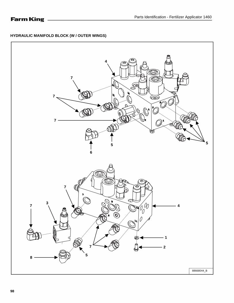
Parts Identification - Fertilizer Applicator 1460
HYDRAULIC MANIFOLD BLOCK (W / OUTER WINGS)
88668044_B
7
4
7
7
6
5 5
8
7
37
5
7
4
1
2
98

Parts Identification - Fertilizer Applicator 1460
ITEM PART NUMBER DESCRIPTION QTY1 00080681 LOCK WASHER, 0.31 PL 42 00087872 BOLT, 0.31” x 0.75” HEX GR 5 PL 43 88662270 RELIEF VALVE, SAE 08 1200 PSI 14 SX014093 HYDRAULIC MANIFOLD BLOCK W / REDUCING 15 SX6400-8 ADAPTER, STRAIGHT, 08 MJIC - 08 ORB 66 SX6500-8 HYDRAULIC FITTING, 08 FJIC x 08 MJIC 17 SX6801-8 HYDRAULIC FITTING, 3/4” MO x 1/2” JIC EL 98 SX6809-8-8 ELBOW, 08 SAE x 08 FJIX 1
PORT# ROUTING LOCATION1 EXTEND (INTO GROUND) SCV #2 HOSE2 RETRACT (RAISE) SCV #2 HOSE3 RETRACT (FOLD IN) SCV #1 HOSE4 EXTEND (FOLD OUT) SCV # 1 HOSE5 ROCKSHAFT CYLINDER BASE END6 ROCKSHAFT CYLINDER SHAFT END7 LH OUTER WING CYLINDER BASE END8 RH OUTER WING CYLINDER BASE END9 LH OUTER WING CYLINDER SHAFT END10 RH OUTER WING CYLINDER SHAFT END11 LH INNER WING CYLINDER SHAFT END12 RH INNER WING CYLINDER SHAFT END13 LH INNER WING CYLINDER BASE END14 RH INNER WING CYLINDER BASE END15 NOT USED (PRESSURE GAUGE PORT)
99

Parts Identification - Fertilizer Applicator 1460
TANK AND PLUMBING ASSEMBLY
88667997-B
810
1013
15
14
16
76
1114
4 2
5
3
12
9
91
17
100

Parts Identification - Fertilizer Applicator 1460
ITEM PART NUMBER DESCRIPTION QTY
1 00087936 BOLT, CSHHP 0.38x 2.5” LG 20
2 88667999 TANK; 1600 ELLIP, 1460 DRILL, CREAM 1
3 88668127 1600 GAL SADDLE / TANK WELDMENT, GREEN 1
88668128 1600 GAL SADDLE / TANK WELDMENT, RED 1
4 SX008882 STRAP, 1000 GAL 5
5 SX013799 TANK BAFFLE, 1600 GALLON ELIP 1
6 SX017672 TANK MEASURE DECAL 2
7 SX12J CLAMP, 3/4” HOSE WORM SCREW 4
8 00087689 BOLT, 0.50” x 1.50” GR 5 HEX PL 12
9 SXFW-038YZ FLATWASHER, 3/8” GR 5 40
10 SXFW-050Y FLATWASHER, 1/2” YZ 24
11 SXHB-075-90 HOSE BARB, 3/4” MPT x 3/4” HB, ELL 4
12 SXLN-038-NIYZ LOCKNUT, 3/8” NYLON INSERT YZ 20
13 SXLN-050-NI-YZ LOCKNUT, 1/2” NYLON INSERT YZ 12
14 SXNW60401 THREADED BULKHEAD, 3/4” 5
15 SXPLUG075 PLUG, 3/4” MPT POLY 1
16 SXSIGHT-34 SIGHT HOSE, 3/4” ID x 1/8” 6.8’
17 SXNW60011 VENTED TANK LID, 16” 1
101

Parts Identification - Fertilizer Applicator 1460
HAND RINSE TANK ASSEMBLY
ITEM PART NUMBER DESCRIPTION QTY1 00080681 LOCK WASHER, 5/16” PL 62 00087872 BOLT, 5/16” x 0.75” HEX GR 5 PL 63 88665010 HAND EYE RINSE TANK ASSEMBLY, - CRM 14 SX014666 TANK BRACKET WELDMENT, 9 GAL. 25 SXBHF0381258YZ BOLT, 3/8” x 1.25” GR 8 YLLWZN 46 SXFW-031-YZ FLAT WASHER, 5/16” YZ 67 SXFW-038YZ FLAT WASHER, 3/8” GRADE 5 48 SXLN-038-NIYZ LOCKNUT, 8” NYLON INSERT YZ 4
88667996-B
1
2
65
78
1
2
6
43
102

Parts Identification - Fertilizer Applicator 1460
HAND / EYE RINSE TANK ASSEMBLY
ITEM PART NUMBER DESCRIPTION QTY1 88664993 RIVET WASHER, 3/8” OD x 3/16” ID 42 88664994 TANK COVER, 9 GAL SCREW CAP 13 88664995 TANK LID, 9 GAL MOLDED 14 88665008 TANK, 9 GAL BUHLER CREAM 15 88665019 SIGHT HOSE, 1/2” ID x 1/8” WALL 16 88664997 LATCH, 07 - 10 - 201 - 12 LIVING BLACK 17 88664998 SPIGOT, 3/4” MATURAL 28 88664999 BUTT HINGE, H03 - 30200 - 171 ZINC 29 88665000 RIVET, AB4 - 6A 2
10 88665001 DRIVE RIVET, 1/8” x 0.359 - 0.391 411 88665002 RIVET, 3/16” x AD64 - AH CLOSED 412 88665003 RIVET, 3/16” x 0.440 LG DOMEHEAD 213 88665006 SPEEDY HOSE CLAMP, 1/2” 114 88665005 HOSE FITTING, 3/4” MPT x 1/2” HB 1
88665010_B6
7
14
13
2
5
14
96
12
1
11
8
10
3
4
103

Parts Identification - Fertilizer Applicator 1460
ACE CENTRIFUGAL PUMP & PLUMBING ASSEMBLY (OPTION)
88668011-D
31
11
7
20
29
7
20
30
17
6
1015
921
24
18
5
22
253
3220
8
2628
19
14
34
33
29
20
7
7
19
2827
24
13
2316
19
281
TO CONTROL PANEL
FROM TANK
104

Parts Identification - Fertilizer Applicator 1460
ITEM PART NUMBER DESCRIPTION QTY
1 88661393 1” PRESSURE SPIKE VALVE, 100 PSI 1
2 88663901 BOLT, 3/8” x 1.50” CSHH GR 5 P 2
3 SX011612 BLACK RUBBER HOSE, 1” 150# 2’
4 SX015747 PRODUCT PUMP MOUNT STRAP 2
5 SX015748 PRODUCT PUMP MOUNT WELDMENT 1
6 SX016538 HYDRAULIC HOSE, 1/2” x 320” 08 FJIC - 08 MORB 2
7 SX150G 2” FLANGED VALVE GASKET 4
8 SX16J CLAMP; 1" X 1/2 STAINLESS 2
9 SX2404-8-8 HYDRAULIC FITTING, 08 MNPT x 08 JIC, STEEL 1
10 SX2501-8-8 HYDRAULIC ADAPTER, 08 MJIC X 08MNPT 1
11 SX28J CLAMP, 1-3/4” x 1/2” STAINLESS 1
12 SX3A1814 HOSEBARB; 1/8” x 1/4” POLY 1
13 SX4JM CLAMP, 1/4” x 5/16” STAINLESS 2
14 SX600432 HOSE, 2” ENFORCER FERT SOL. 2.5’
15 SX6500-8 HYDRAULIC FITTING, 08 FJIC x 08 MJIC 1
16 SX73HD SPINWELD; 1/4” FPT RAISED 1
17 SX8010-15P HYDRAULIC QUICK COUPLER, UNIV. POPPET 2
18 SXBH0381005YZ BOLT, 3/8” x 1” YLLW ZNC 4
19 SXFC100BJ CLAMP, 1” 3
20 SXFC200 COUPLING, 2” x 2” FPT NYLON 4
21 SXFMCSC150HYD PUMP, CAST, SC SEAL, 1.5” ACE 1
22 SXFW-038YZ FLATWASHER, 3/8” GR 5 6
23 SXHB-025-90 HOSE BARB, 1-4 MPT x 1/4” HB EL 1
24 SXK3150-025 HOSE; 1/4” VINYL REINFORC CLR 12.5’
25 SXLN-038-NIYZ LOCKNUT, 3/8” NYLON INSERT YZ 6
26 SXM100BRB HOSE BARB, 1” x 1” STRAIGHT 1
27 SXM100BRB90 HOSE BARB, 1” FLANGE ELBOW 1
28 SXM100G 1” FLANGED VALVE GASKET 3
29 SXM200100TEE TEE, 2” x 1” 2
30 SXM200125MPT MANIFOLD, 2” FLG, 1-1/4” MPT 1
31 SXM200150BRB90 HOSE BARB, 2” FLG x 1-1/2” HB, EL 1
32 SXM200150MPT MANIFOLD, 2” FLG, 1-1/2” MPT 1
33 SXM200BRB90 HOSE BARB, 2” HB, 2” FLG, EL 1
34 SXTBC256 T-BOLT CLAMP, 2-11/32” - 25/8 1
105

Parts Identification - Fertilizer Applicator 1460
TANK QUICK FILL PLUMBING ACE CENTRIFUGAL PLUMBING ASSEMBLY
88668123_B
TO PUMP
FROM TANK
2
10
17
13
4
17 139
12
15
1512
5
1215
3
12 157
1
14
17
1215
18
11
19
20
3
1215
8
16
106

Parts Identification - Fertilizer Applicator 1460
ITEM PART NUMBER DESCRIPTION QTY
1 SXTBC350 T-BOLT CLAMP, 3-1/2” x 3-13/16” 2
2 SXTBC256 T-BOLT CLAMP, 2-11/32” x 2-5/8” 1
3 SXMV300 VALVE, 3” STANDARD PORT MANIFOLD VALVE 2
4 SXMV220CF VALVE, 2” FP FLG BANJO 1
5 SXMBF300BD BULKHEAD, 3” BOLT FLANGED BD 1
6 SXM300TEE TEE, 3” FLANGED 1
7 SXM300BRB HOSE BARB, 3” FLG x 3” HB POLY 2
8 SXM300A COUPLER, 3” FLG x 3” CAM COUPLER BANJO 1
9 SXM300200CPG MANIFOLD FITTING, 3” x 2” FULL 1
10 SXM200BRB90 HOSE BARB, 2” HB x 2” FLG EL 1
11 SXLN - 050 NI - YZ LOCKNUT, 1/2” NYLON INSERT YZ 2
12 SXFC300BJ CLAMP, 3” BANJO 6
13 SXFC200BJ CLAMP, 2” 6
14 SX600448 HOSE, 3” EPDM W / POLY HELIX & FABR 3’
15 SX300G GASKET, 3” BANJO 6
16 SX300CAP COUPLING, 3” CAM LEVER CAP 1
17 SX150G GASKET, 2” FLANGED VALVE 2
18 SX014105 VALVE MOUNTING PLATE 1
19 88662075 BOLT, 0.38” x 5.50” CSHH 316SS 6
20 00087670 BOLT, 0.50” x 1.25” HEX GR 5 PL 2
107

Parts Identification - Fertilizer Applicator 1460
JOHN BLUE GROUND DRIVE MOUNT ASSEMBLY
SX014114-D
11
29
5
720
713
26
9
35
75 6
8
4
30
33
34
15
248
1
27
18
28
10
5, 7
31
4
2217
193, 16
2, 14
25, 21
12
7
20
23
17
9
20
CHAIN ROUTING(Right Side)
108

Parts Identification - Fertilizer Applicator 1460
ITEM PART NUMBER DESCRIPTION QTY
1 SXNUT-075-J NUT, 3/4” 2
2 SXLW-050 LOCK WASHER, 1/2” 5
3 SXLW-038 LOCK WASHER, 3/8” 5
4 SXLN-075-CL LOCKNUT, 3/4” CENTER LOCKNUT 2
5 SXLN-062-CL LOCKNUT, 5/8” CENTER LOCKNUT 2
6 SXLN-038-NI LOCKNUT, 3/8” NYLON INSERT 1
7 SXFW-062 FLAT WASHER, 5/8” 10
8 SXFW-038 FLAT WASHER, 3/8” 2
9 SXDS50A17 IDLER SPROCKET, W / BEARINGS 1
10 SXBH-075-250-5 BOLT; 3/4” x 2-1/2” GR 5 1
11 SXBH-062-600-5 BOLT, 5/8” x 6” HEX GR 5 4
12 SXBH-062-500-5 BOLT, 5/8” x 5” HEX GR 5 1
13 SXBH-062-250-5 BOLT, 5/8” x 2-1/2” HEX GR 5 1
14 SXBH-050-200-20 BOLT, 1/2” x 2” GR 5 5
15 SXBH-038-150-5 BOLT, 3/8” x 1-1/2” GR 5 1
16 SXBH-038-075-5 BOLT, 3/8” x 3/4” GR 5 5
17 SXA-1342-AP-BLK SPROCKET, 60 TOOTH, GRND DRV 1
18 SX73362B SPRING, 1400 GROUND DRIVE, BLK 1
19 SX106190-01 HUB SPROCKET ADAPTER, 4 BOLT 1
20 SX013520 SPROCKET, IDLER,50-13,5/8 BORE 2
21 SX008224 CHAIN, IDLER TO WHEEL 1
22 SX008222 TUBE, SPACER COLLAR 5
23 SX008221 TUBE, SPACER BUSHING 1
24 SX008170 SHAFT WELDMENT 1
25 SX008053 #50 CONNECTING LINK 1
26 SX008025 COLLAR, 3/4” 2 PC CLAMP ON 1
27 SX008022 MAIN FRAME END MOUNT WELDMENT 1
28 SX008018 THREADED ROD HALF WELDMENT 1
29 SX008014 BACKING BOLT PLATE 2
30 SX008013 FRAME AND PUMP MOUNT WELDMENT 1
31 SX008003 SWING ARM AND SPINDLE WELDMENT 1
32 88660947 TIRE ASSEMBLY, 5 x 15 1
33 88661526 TUBE, SPACER, PIVOT, SPRING 2
34 SXBH-075-650-5 BOLT, 3/4” x 6.-1/2” GR 5 1
35 SXFW-075 FLATWASHER, 3/4” 2
36 SXG1637 45 DEG GREASE ZERK, 1/4” - 28 1
109

Parts Identification - Fertilizer Applicator 1460
JOHN BLUE TWIN PUMP ASSEMBLY
88668015-B TWIN
2
5
2314
1922
3
1510
2419
14
23
4
17 (FROM TANK)
12 (TO MONITOR KIT)
20
125
921
1318
8
21
11
6
7
CHAIN ROUTING(Right Side)
110

Parts Identification - Fertilizer Applicator 1460
ITEM PART NUMBER DESCRIPTION QTY
1 00080680 LOCK WASHER, 0.375” PL 4
2 00087936 BOLT, CSHHP 0.38” x 2.5” LG 4
3 88660940 DUAL PISTON PUMP 1
4 88660945 90° ELBOW, 1.50” MPT x 1.50” FPT- POLY 1
5 88660946 PUMP MOUNT SPACER 4
6 88660948 50 SERIES / 81 PITCH CHAIN 1
7 88668053 GROUND DRIVE ADAPTER ASSEMBLY 1
8 88668120 LOCKNUT, 5/8” CENTER LOCK YZ 1
9 88668141 GROUND DRIVE MOUNT ASSEMBLY 1
10 88669452 T-BOLT CLAMP, 2.38” x 2.69” 1
11 SX008053 #50 CONNECTING LINK 1
12 SX012412 HOSE, 1-1/2” 150# EPDM 6.5’
13 SX013520 IDLER SPROCKET, 50-13, 5/8” BORE 1
14 SX150G 2” FLANGED VALVE GASKET 2
15 SX28J STAINLESS CLAMP; 1-3/4” x 1/2” 1
16 SX3NS12 STRAP, 11-1/4” BLACK 21 8
17 SX600432 HOSE, 2” ENFORCER, FERT SOL. 15’
18 SXBH0622505YZ BOLT, 5/8” x 2-1/2” GR 5 1
19 SXFC200BJ 2” BANJO CLAMP 2
20 SXFW-038YZ FLAT WASHER, 3/8” GR 5 4
21 SXFW-062YZ FLAT WASHER, 5/8” YLLWZN 4
22 SXM200150BRB90 HOSE BARB, 2” FLG x 1-1/2” HB, EL 1
23 SXM200150MPT MANIFOLD, 2” FLG x 1-1/2” MPT 2
24 SXM200BRB HOSE BARB, 2” FLG x 2” HB 1
25 SXNUT-038YZ NUT, 3/8” GR 5 4
111

Parts Identification - Fertilizer Applicator 1460
RAVEN CONTROL PLUMBING ASSEMBLY
88668014_D
15
29
22
15
13
22
15
2716
11
3
32
26
11
16
27
12
2
15 22
15
28 1522
15
20
7 23
25
20
6
23
25
19
20
9
23
14
22 15
24
28
416
821 10 23
15
22
27
16
11
16
1522
27
25
3015 22
31
112

Parts Identification - Fertilizer Applicator 1460
ITEM PART NUMBER DESCRIPTION QTY
1 00280260 BOLT, 3/8” x 3” CSHH GR 8 PL 2
2 88668020 U-BOLT, 3/8” x 2-1/2” x 4” RND YZ 2
3 88668021 U-BOLT, 3/8” x 3-3/4” x 5” RND YZ 1
4 88668032 U-BOLT, 5/16” x 1” x 1-3/4” YZ 4
5 SX004108 STRAINER MOUNTING PLATE 1
6 SX004114 3” FLOW METER MOUNT 1
7 SX006069 FLANGED STRAINER MOUNT 1
8 SX007601 VALVE MOUNTING PLATE 1
9 SX007659 RAVEN REGULATING VALVE BRACKET 1
10 SX007777 PANEL MOUNTING TUBE 2
11 SX012412 HOSE, 1-1/2” 150# EPDM 28’
12 SX01663 2” ELECTRIC VALVE, BANJO W / PACKARD 1
13 SX063 - 0171 - 793 FLOW METER, RFM 60P 1
14 SX063 - 0172 - 125 1” CONTROL VALVE POLY 1
15 SX150G 2” FLANGED VALVE GASKET 10
16 SX28J STAINLESS CLAMP, 1-3/4” 1/2” 6
17 SX3NS12 STRAP, 11-1/4” BLACK 21 10
18 SX3NS8 STRAP, 7-1/4” BLACK 15
19 SX48J HOSE CLAMP, 3” WORK SCREW 1
20 SXBH0250758YZ BOLT, 1/4” x 3/4” GR 8 6
21 SXBH0251758YZ BOLT, 1/4” x 1-3/4” GR 8 ZINC 4
22 SXFC200BJ 2” BANJO CLAMP 10
23 SXLN - 038 - NIYZ LOCKNUT, 1/4” NYLON INSERT 10
24 SXLN - 031 - NIYZ LOCKNUT, 5/16” NYLON INSERT YZ 8
25 SXLN - 025 - NIYZ LOCKNUT, 3/8” NYLON INSERT YZ 8
26 SXLST1550 SCREEN, 1-1/4” & 1-1/2” T 50 MESH 1
27 SXM200150BRB HOSE BARB, 2” FLG x 1-1/2” HB EL 4
28 SXM200150BRB90 HOSE BARB, 2” FLG x 1-1/2” HB 2
29 SXM200CPG FLANGE, 2” x 2” POLY 1
30 SXM200PLG 2” BANJO PLUG, FLANGE 1
31 SXM200TEE 2” FLANGED BANJO TEE 1
32 SXMLST150 - HB 2” HEAD & BODY FLANGED STRAINER 1
113

Parts Identification - Fertilizer Applicator 1460
SPRAY MONITORS
88668329_B
11
16
20
19
12
14
8
10
18
3
1
6
7
2
15
9
17
35
13
4
114

Parts Identification - Fertilizer Applicator 1460
ITEM PART NUMBER DESCRIPTION QTY1 00087845 BOLT, 1/4” x 2-1/2” HEX GR 5 AS REQ.2 88668003 ASSY; MONITOR, SINGLE COLUMN AS REQ.
88668887 ASSY, MONITOR, 3 COLUMN AS REQ.88664836 ASSY, MONITOR, 4 COLUMN AS REQ.88664835 ASSY, MONITOR, 5 COLUMN AS REQ.88664838 ASSY, MONITOR, 6 COLUMN AS REQ.88664834 ASSY, MONITOR, 7 COLUMN AS REQ.88664837 ASSY, MONITOR, 8 COLUMN AS REQ.
3 88668033 U-BOLT, 5/16” x 1-1/4” x 2” YZ 44 SX000418 MONITOR CROSS BAR WELDMENT, 27” 15 SX000419 MONITOR STAND UPRIGHT, 30” 16 SX002037 SINGLE MONITOR, U-PIN 27 SX002138 MONITOR CAP, PLUG 28 SX002140 MONITOR O-RING, BUNA 29 SX003930 MONITOR BAND CLIP 6
10 SX007306 MONITOR TEE PORT W / GAUGE 111 SX28J STAINLESS CLAMP, 1-3/4” x 1/2” 112 SX3SE14 STREET ELBOW, 1/4” x 1/4” POLY 113 SXC2040673 MONITOR BLACK BAG, 40” x 46” x 0.008 114 SXGG100 100 PSI GAUGE, 2-1/2” LIQUID FILLED 115 SXH HOSE CLAMP, 1/2” SPEEDY 516 SXHB-150-90 HOSE BARB ELBOW; 1-1/2” MPT XHB POL 117 SXLN-025-NIYZ LOCKNUT, 1/4” NYLON INSERT AS REQ.18 SXLN-031-NIYZ LOCKNUT, 5/16” NYLON INSERT YZ 119 SXNIP100-4 NIPPLE, 1” x 4” MPT POLY 120 SXRC150-100 REDUCING COUPLING, 1-1/2” x 1” 1
115

Parts Identification - Fertilizer Applicator 1460
SINGLE COLUMN MONITOR ASSEMBLY
ITEM PART NUMBER DESCRIPTION QTY
1 SX002037 SINGLE MONITOR U-PIN 2
2 SX002135 1/2” HOSE BARB 1
3 SX002137 SINGLE MONITOR FLOAT STOP 1
4 SX002139 SINGLE COLUMN MONITOR 1
5 SX002140 MONITOR O-RING, BUNA 2
6 SX8165105 RED GLASS MONITOR BALL 1
7 SXSS316-200 STAINLESS STEEL MONITOR BALL 1
88668003-B
2
5
3
6
1
7
45
1
116

Parts Identification - Fertilizer Applicator 1460
MICROSWITCH
SXSB010510 MICROSWITCH
12
3
45
6
7
8
910
ITEM PART NUMBER DESCRIPTION QTY
1 88666365 SWITCH MOUNTING PLATE, 12 GA 1
2 88668038 LOCKNUT, 10-24 NYLON INSERT YZ 2
3 88668039 BOLT, 1/4” x 1.25” TAP GR 5 YZ 1
4 88666366 SWITCH ACTIVATION PLATE, 12 GA 1
5 SXFW-038YZ FLATWASHER, 3/8” GR 5 2
6 00012012 BOLT, CSHH 3/8” x 0.75” GR 5 P 2
7 SXLN-025-NIYZ LOCKNUT; 1/4” NYLON INSERT 1
8 88662125 LOCKNUT, 3/8” NYLON INSERT FLG GR 5 YZ 2
9 SXSB010510 MICROSWITCH SMARTBO WIRE ASSEMBLY, 42 1 1
10 86511926 BOLT; 10-24 x 1.75” MACH YZ 2
117

Parts Identification - Fertilizer Applicator 1460
COULTER W / KNIFE GROUP
12 Row - 30” Spacing / 11 Coulters
12 Row - 36” Spacing / 11 Coulters
12 Row - 38” Spacing / 11 Coulters
12 Row - 40” Spacing / 11 Coulters
SX014138_CL
1
88661376
3
2
ITEM PART NUMBER DESCRIPTION QTY1 88660890 RH STRAIGHT SHANK COULTER ASSEMBLY, W/ KNIFE 52 88660892 RH OFFSET SHANK COULTER ASSEMBLY, W/ KNIFE 63 88661376 4 x 6 CLAMP KIT 11
ITEM PART NUMBER DESCRIPTION QTY1 88660890 RH STRAIGHT SHANK COULTER ASSEMBLY, W/ KNIFE 72 88660892 RH OFFSET SHANK COULTER ASSEMBLY, W/ KNIFE 43 88661376 4 x 6 CLAMP KIT 11
ITEM PART NUMBER DESCRIPTION QTY1 88660890 RH STRAIGHT SHANK COULTER ASSEMBLY, W/ KNIFE 92 88660892 RH OFFSET SHANK COULTER ASSEMBLY, W/ KNIFE 23 88661376 4 x 6 CLAMP KIT 11
ITEM PART NUMBER DESCRIPTION QTY1 88660890 RH STRAIGHT SHANK COULTER ASSEMBLY, W/ KNIFE 112 88660892 OFFSET SHANK COULTER ASSEMBLY, W/ KNIFE -3 88661376 4 x 6 CLAMP KIT 11
118

Parts Identification - Fertilizer Applicator 1460
16 Row - 22” Spacing / 15 Coulters
16 Row - 30” Spacing / 17 Coulters
24 Row - 22” Spacing / 23 Coulters
ITEM PART NUMBER DESCRIPTION QTY1 88660890 RH STRAIGHT SHANK COULTER ASSEMBLY, W/ KNIFE 92 88660892 RH OFFSET SHANK COULTER ASSEMBLY, W/ KNIFE 63 88661376 4 x 6 CLAMP KIT 15
ITEM PART NUMBER DESCRIPTION QTY1 88660894 STRAIGHT SHANK COULTER ASSEMBLY, W/ INJECTOR 102 88660895 OFFSET SHANK COULTER ASSEMBLY, W/ INJECTOR 73 88661376 4 x 6 CLAMP KIT 17
ITEM PART NUMBER DESCRIPTION QTY1 88660890 RH STRAIGHT SHANK COULTER ASSEMBLY, W/ KNIFE 52 88660892 RH OFFSET SHANK COULTER ASSEMBLY, W/ KNIFE 63 88661376 4 x 6 CLAMP KIT 23
119
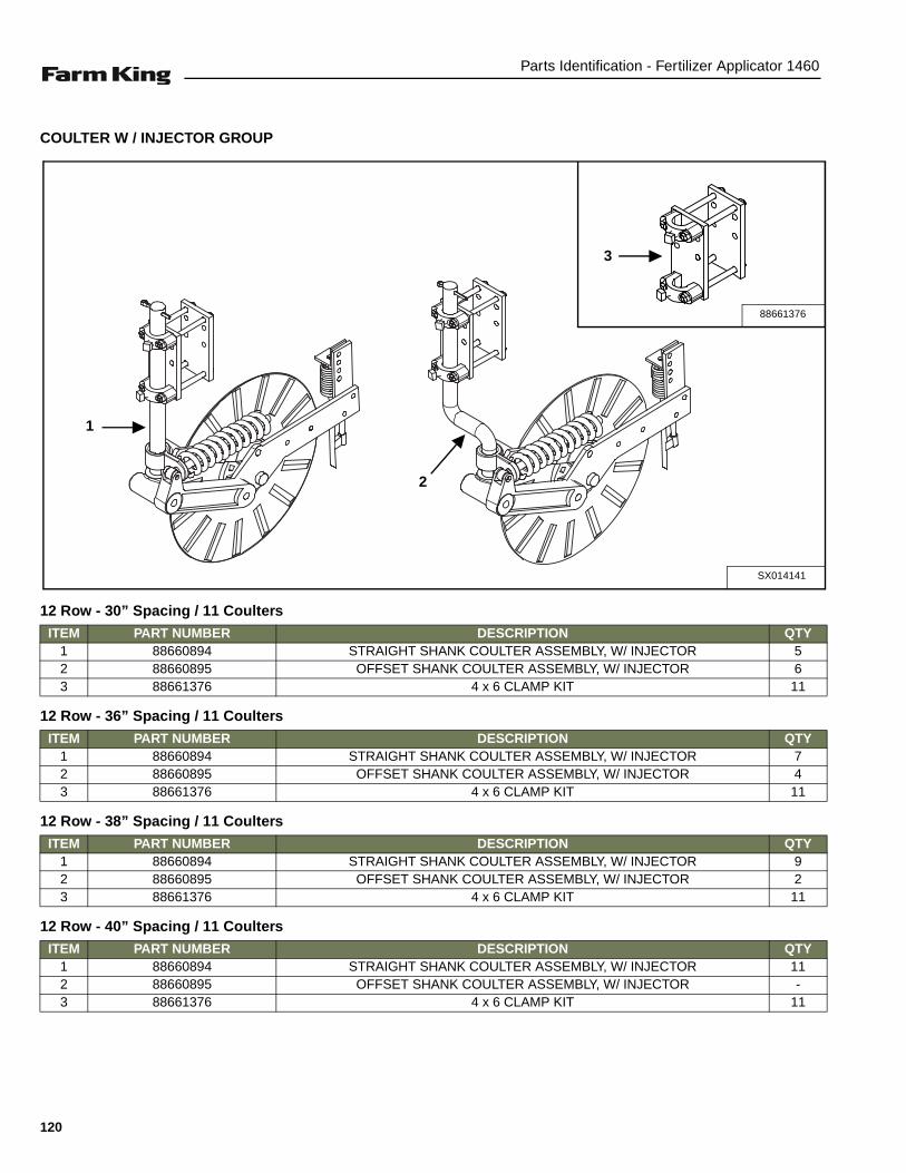
Parts Identification - Fertilizer Applicator 1460
COULTER W / INJECTOR GROUP
12 Row - 30” Spacing / 11 Coulters
12 Row - 36” Spacing / 11 Coulters
12 Row - 38” Spacing / 11 Coulters
12 Row - 40” Spacing / 11 Coulters
SX014141
1
88661376
3
2
ITEM PART NUMBER DESCRIPTION QTY1 88660894 STRAIGHT SHANK COULTER ASSEMBLY, W/ INJECTOR 52 88660895 OFFSET SHANK COULTER ASSEMBLY, W/ INJECTOR 63 88661376 4 x 6 CLAMP KIT 11
ITEM PART NUMBER DESCRIPTION QTY1 88660894 STRAIGHT SHANK COULTER ASSEMBLY, W/ INJECTOR 72 88660895 OFFSET SHANK COULTER ASSEMBLY, W/ INJECTOR 43 88661376 4 x 6 CLAMP KIT 11
ITEM PART NUMBER DESCRIPTION QTY1 88660894 STRAIGHT SHANK COULTER ASSEMBLY, W/ INJECTOR 92 88660895 OFFSET SHANK COULTER ASSEMBLY, W/ INJECTOR 23 88661376 4 x 6 CLAMP KIT 11
ITEM PART NUMBER DESCRIPTION QTY1 88660894 STRAIGHT SHANK COULTER ASSEMBLY, W/ INJECTOR 112 88660895 OFFSET SHANK COULTER ASSEMBLY, W/ INJECTOR -3 88661376 4 x 6 CLAMP KIT 11
120

Parts Identification - Fertilizer Applicator 1460
16 Row - 22” Spacing / 15 Coulters
16 Row - 30” Spacing / 15 Coulters
16 Row - 30” Spacing / 17 Coulters
24 Row - 22” Spacing / 23 Coulters
ITEM PART NUMBER DESCRIPTION QTY1 88660894 STRAIGHT SHANK COULTER ASSEMBLY, W/ INJECTOR 92 88660895 OFFSET SHANK COULTER ASSEMBLY, W/ INJECTOR 63 88661376 4 x 6 CLAMP KIT 15
ITEM PART NUMBER DESCRIPTION QTY1 88660894 STRAIGHT SHANK COULTER ASSEMBLY, W/ INJECTOR 92 88660895 OFFSET SHANK COULTER ASSEMBLY, W/ INJECTOR 63 88661376 4 x 6 CLAMP KIT 15
ITEM PART NUMBER DESCRIPTION QTY1 88660894 STRAIGHT SHANK COULTER ASSEMBLY, W/ INJECTOR 102 88660895 OFFSET SHANK COULTER ASSEMBLY, W/ INJECTOR 73 88661376 4 x 6 CLAMP KIT 17
ITEM PART NUMBER DESCRIPTION QTY1 88660894 STRAIGHT SHANK COULTER ASSEMBLY, W/ INJECTOR 92 88660895 OFFSET SHANK COULTER ASSEMBLY, W/ INJECTOR 63 88661376 4 x 6 CLAMP KIT 15
121

Parts Identification - Fertilizer Applicator 1460
COULTER ASSEMBLY (STRAIGHT)
RH W / Knife
ITEM PART NUMBER DESCRIPTION QTY1 SX2570-375 HUB CAP 12 88664879 1/8” x 1 1/4” COTTER PIN, BLACK 13 88664880 5/8”-18 SLOTTED HEX NUT BLK 44 88664881 1/2” MED LOCKWASHER ZP 45 88664882 1/2”-13 HEX NUT ZP 46 88661371 RIPPLE BLADE 20” 1
88667047 SMOOTH BLADE7 88664883 5/8” FLATWASHER, 1/4” +/- 0.010 THICK 18 SX2550-027 CONE, LM67048 29 88664884 HUB PRESSED ASSY 1
SX2550-029 CUP (PRE-ASSY W/9) LM67010 210 88664885 TRIPLE LIP SEAL, NTI #1812-4 111 88664886 1/2”-13 x 1 1/4” CAR BOLT GR5 ZP 412 88664887 1/2”-13 LOCK HEX NUT ZP 1
3
21
46
5
4 6
4443
42
4140
39
37
3836
35
2633 32
31
15
3029
34
28
2725
2019
18
15
1213
1617
14
2123
9
8 10
11
7
88661366 R B
2224
47
48
45
49
50
122
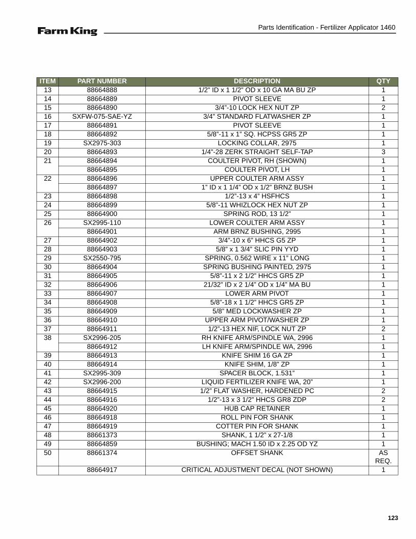
Parts Identification - Fertilizer Applicator 1460
ITEM PART NUMBER DESCRIPTION QTY13 88664888 1/2” ID x 1 1/2” OD x 10 GA MA BU ZP 114 88664889 PIVOT SLEEVE 115 88664890 3/4”-10 LOCK HEX NUT ZP 216 SXFW-075-SAE-YZ 3/4” STANDARD FLATWASHER ZP 117 88664891 PIVOT SLEEVE 118 88664892 5/8”-11 x 1” SQ. HCPSS GR5 ZP 119 SX2975-303 LOCKING COLLAR, 2975 120 88664893 1/4”-28 ZERK STRAIGHT SELF-TAP 321 88664894 COULTER PIVOT, RH (SHOWN) 1
88664895 COULTER PIVOT, LH 122 88664896 UPPER COULTER ARM ASSY 1
88664897 1” ID x 1 1/4” OD x 1/2” BRNZ BUSH 123 88664898 1/2”-13 x 4” HSFHCS 124 88664899 5/8”-11 WHIZLOCK HEX NUT ZP 125 88664900 SPRING ROD, 13 1/2” 126 SX2995-110 LOWER COULTER ARM ASSY 1
88664901 ARM BRNZ BUSHING, 2995 127 88664902 3/4”-10 x 6” HHCS G5 ZP 128 88664903 5/8” x 1 3/4” SLIC PIN YYD 129 SX2550-795 SPRING, 0.562 WIRE x 11” LONG 130 88664904 SPRING BUSHING PAINTED, 2975 131 88664905 5/8”-11 x 2 1/2” HHCS GR5 ZP 132 88664906 21/32” ID x 2 1/4” OD x 1/4” MA BU 133 88664907 LOWER ARM PIVOT 134 88664908 5/8”-18 x 1 1/2” HHCS GR5 ZP 135 88664909 5/8” MED LOCKWASHER ZP 136 88664910 UPPER ARM PIVOT/WASHER ZP 137 88664911 1/2”-13 HEX NIF, LOCK NUT ZP 238 SX2996-205 RH KNIFE ARM/SPINDLE WA, 2996 1
88664912 LH KNIFE ARM/SPINDLE WA, 2996 139 88664913 KNIFE SHIM 16 GA ZP 140 88664914 KNIFE SHIM, 1/8” ZP 141 SX2995-309 SPACER BLOCK, 1.531” 142 SX2996-200 LIQUID FERTILIZER KNIFE WA, 20” 143 88664915 1/2” FLAT WASHER, HARDENED PC 244 88664916 1/2”-13 x 3 1/2” HHCS GR8 ZDP 245 88664920 HUB CAP RETAINER 146 88664918 ROLL PIN FOR SHANK 147 88664919 COTTER PIN FOR SHANK 148 88661373 SHANK, 1 1/2” x 27-1/8 149 88664859 BUSHING; MACH 1.50 ID x 2.25 OD YZ 150 88661374 OFFSET SHANK AS
REQ.88664917 CRITICAL ADJUSTMENT DECAL (NOT SHOWN) 1
123

Parts Identification - Fertilizer Applicator 1460
COULTER ASSEMBLY (STRAIGHT) (CONT’D)
RH W / Injector
88661368 R B-1
1
7
4
13
52
6
13 12
318
19
20
22
21
23
12 13
17
11
16
10
8
15
9
13
12
14
24
25
124

Parts Identification - Fertilizer Applicator 1460
ITEM PART NUMBER DESCRIPTION QTY1 00012008 1/2”-13 x 1 1/2” HHCS GR5 ZP 22 00012071 1/2”-13 x 1” HHCS GR5 ZP 23 88664913 KNIFE SHIM, 16 GA. ZP 14 88664914 KNIFE SHIM, 1/8” ZP 25 88664922 ADJUSTMENT PLATE, INJECTOR 26 SX2995-320 SPACER, INJECTOR 17 SX2995-301 INJECTOR MOUNT PLATE 18 88664919 5/16” x 2-1/2” COTTER PIN ZP 19 88664918 3/8” x 2-1/2” ROLL PIN ZP 1
10 88664892 5/8”-11 x 1” SQ HCPSS GR5 ZP 111 88664886 1/2”-13 x 1 1/4” CAR BOLT GR5 412 88664882 1/2”-13 HEX NUT ZP 813 88664881 1/2” MED LOCKWASHER ZP 914 88664923 GEN III COULTER ARM ASSY (W/INJECT) 115 88661373 SHANK, 1 1/2” x 27-1/8 116 SX2975-303 2975 LOCKING COLLAR 117 88661371 .157” x 20" RIPPLE BLADE 1
88667047 SMOOTH BLADE 118 SX2995-131 SPRING INJECTOR ASSEMBLY 119 88664924 3" NIPPLE, 1/4 NPT SS 120 88664925 INJECTOR ROD W A 1/2”-13 121 88664926 1/2”-13 x 2” CAR BOLT GR5 ZP 222 88664927 1/2”-13 JAM HEX NUT ZP 123 88664920 HUB CAP RETAINER 124 88664859 BUSHING; MACH 1.50 ID x 2.25 OD YZ 125 88661374 OFFSET SHANK AS
REQ.
125

Parts Identification - Fertilizer Applicator 1460
COULTER ARM ASSEMBLY
RH W / Injector
88661368 R B-2
12
17
10
8
12
1
3
4
2
5
13
1314
159
16
11
7
6
126

Parts Identification - Fertilizer Applicator 1460
ITEM PART NUMBER DESCRIPTION QTY1 88664927 1/2”-13 JAM HEX NUT ZP 12 88664904 2975 SPRING BUSHING PAINTED 13 SX2550-795 SPRING, 0.562” WIRE x 11” LONG 14 88667464 10” POLY HELPER SPRING 15 88664929 COULTER PIVOT, RH (SHOWN) 1
88664895 COULTER PIVOT, LH 16 812435 1/4” x 1 3/4” COTTER PIN ZYD 17 88667463 1 17/64” ID x 1 7/8” OD x 14GA MB 18 88664900 SPRING ROD, 13-1/2” 19 88664879 1/8” x 1 1/4” COTTER PIN BLACK 1
10 88664903 5/8” x 1 3/4” SLIC PIN ZYD 111 88664932 GEN III W / KNIFE ARM WA RH (SHOWN) 1
88664933 GEN III W / KNIFE ARM WA LH 112 88664884 HUB PRESSED ASSEMBLY 1
88664893 1/4”-28 ZERK STRAIGHT SELF-TAP 1SX2550-029 CUP, LM67010 2
88664934 PLOW COULTER HUB CASTING 113 SX2550-027 CONE, LM67048 214 88664883 5/8” FLATWASHER, 1/4” +/- 0.010 THICK 115 88664880 5/8”-18 SLOTTED HEX NUT, BLACK 116 SX2570-375 HUB CAP, WILTON #909902 117 88664885 TRIPLE LIP SEAL, NTI #1812-4 1
127

Parts Identification - Fertilizer Applicator 1460
COULTER CLAMP KIT (4X6 BAR)
ITEM PART NUMBER DESCRIPTION QTY1 88664921 BOLT, 1/2”-13 x 7” HHCS GR 5 ZP *42 88664928 UNIVERSAL CLAMP PLATE *23 SX2990-360 DRILLED CLAMP CASTING *24 88664892 SET SCREW, 5/8”-11 x 1” SQ. HCPSS GR 5 ZP *25 88664887 LOCKNUT, 1/2”-13 HEX ZP *4
* Quantity Per Coulter.
88661376-B
1
4
3
2
2
5
128

Parts Identification - Fertilizer Applicator 1460
COULTER HOSE ASSEMBLY
ITEM PART NUMBER DESCRIPTION QTY1 88661128 HOSE BARB, 11/16” MPST x 1/2” HB 12 SX000812 HOSE, 1/2” 150# EPDM 0.6’3 SX3A1412G HOSE BARB, 1/4” MPT x 1/2” HB 14 SX402910 CAP & GASKET 1/4” THRD QT BLK 15 SX8J STAINLESS CLAMP, 1/2” x 1/2” 16 SXH HOSE CLAMP, 1/2” SPEEDY 27 SXQJT8360-NYB CHECK VALVE DIAPHRAGM 1
88668034_B
1 3
5
26
4
7
6
129

Parts Identification - Fertilizer Applicator 1460
GAUGE WHEEL GROUP LH / RH
ITEM PART NUMBER DESCRIPTION QTY1 00280223 BOLT, 3/4” x 6.50” CSHH GR 5 P NA2024 22 88668005 PIN CLIP, 0.177” x 3-3/4” ZINC 13 SX011506 TIRE & WHEEL ASSEMBLY, 7.6-15SL 14 SX014057 FLAT, 0.75” x 9.25” W / HOLES BLACK 15 SX014123 SPINDLE TUBE WELDMENT 16 SX015872 LONG GAUGE WHEEL BRACKET WELDMENT 17 SXLN-075-NI-YZ LOCKNUT, 3/4” NYLON INSERT YZ 28 SXPHI-100-525 HITCH PIN, 1” x 5-1/4” 1
SX014122-B
2
3
1
6
7
5
4
8
LHASSEMBLY
RHASSEMBLY
130

Parts Identification - Fertilizer Applicator 1460
GAUGE WHEEL HUB ASSEMBLY (256 - 6 - 6 - 4.62)
ITEM PART NUMBER DESCRIPTION QTY
1 88665707 HUB W / CUPS 1
2 88665708 OUTER CUP 1
3 88665709 OUTER CONE 1
4 88665710 INNER CUP 1
5 88665711 INNER CONE 1
6 88665712 STUD 6
7 88665713 HUB CAP 1
8 88665714 GREASE SEAL 1
9 88665715 NUT 6
SX011503-B
9
3
5
6
7
1
2
8
4
NOTE: Tighten LUG NUTS to 150 Foot Pounds of torque, Do Not Lubricate.
131
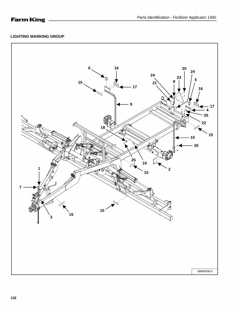
Parts Identification - Fertilizer Applicator 1460
LIGHTING MARKING GROUP
88668008-D
15
6 16
17
9
21
24
823
2024
5
16
174
25
22
1510
26
2
19
15
1515
3
7
1
25
18
132

Parts Identification - Fertilizer Applicator 1460
ITEM PART NUMBER DESCRIPTION QTY
1 86511926 MACHINE BOLT, 10-24 x 1.75” YZ2 2
2 88668009 U-BOLT, 1/2” x 7.38” x 7.25” GR 5 YZ 2
3 88668038 LOCKNUT, 10-24 NYLON INSERT YZ 2
4 SX004499 LIGHT / DECAL SHEET, BLACK 2
5 SX004560 TURN / TAIL LAMP 2
6 SX004561 AMBER FLASH / WARNING TAIL LAMP 2
7 SX006978 TURN SIGNAL MODULE, (PWI) 1
8 SX013588 SLOW MOVING VEHICLE (SMV) SIGN MOUNT 1
9 SX014076 RS LIGHT BRACKET WELDMENT 1
10 SX014081 LS LIGHT BRACKET WELDMENT 1
11 SX014098 1460 RED LIGHT HARNESS 1
12 SX014099 1460 AMBER LIGHT HARNESS 1
13 SX014100 FRONT TO REARHARNESS 1
14 SX014612 TRACTOR / IMPLEMENT HARNESS 1
15 SX17-5910 AMBER REFLECTOR DECAL, 2” x 9” 10
16 SX17-5915 RED REFLECTOR DECAL, 2” x 9” 4
17 SX17-5920 DAY ORANGE DECAL, 2” x 9” 4
18 SX21294 HEAVY DUTY CABLE TIE MOUNT 12
19 SX3NS12 STRAP, 11-1/4” BLACK 21 20
20 SXBH0250758YZ BOLT, 1/4” x 3/4” GR 8 2
21 SXBH0251005YZ BOLT, 1/4” x 1” GR 5 2
22 SXFW-038YZ FLATWASHER, 3/8” GR 5 4
23 SXJD5403 SLOW MOVING VEHICLE (SMV) SIGN 1
24 SXLN-025-NIYZ LOCKNUT, 1/4” NYLON INSERT 4
25 SXLN-038-NIYZ LOCKNUT, 3/8” NYLON INSERT YZ 16
26 SXLN-050-NI-YZ LOCKNUT, 1/2” NYLON INSERT YZ 4
133

Parts Identification - Fertilizer Applicator 1460
ELECTRICAL HARNESSES / ROUTING
ITEM PART NUMBER DESCRIPTION QTY
1 SX014611 HYDRAULIC SOLENOID TEE HARNESS 1
2 SX005813 MICRO SWITCH 5’ EXTENSION HARNESS, SPECIAL 1
3 SX014610 MICRO SWITCH 15’ EXTENSION HARNESS, SPECIAL 1
ELECTRICAL
1
2
3
134

Parts Identification - Fertilizer Applicator 1460
RUNNING GEAR HUB ASSEMBLY (11.25BC, 15000#)
ITEM PART NUMBER DESCRIPTION QTY
1 88665668 BEARING CONE 1
2 88665669 GREASE SEAL 1
3 88665670 OUTER CONE BEARING 1
4 88665671 WHEEL STUD 10
5 88665672 HUBCAP GASKET 1
6 88665673 HUB CAP 1
7 SXBH031-050-5 BOLT, 5/16” x 1/2” GR 5 4
8 SX913571 LUG NUT, 3/4”-16 FLANGED 10
9 88665675 HUB, W / CUPS 1
10 88665676 OUTER CUP 1
SX289126-B
2
49
8
10
3
5
6
7
1
NOTE: Tighten LUG NUTS to 420 Foot Pounds of torque, Do Not Lubricate.
135

Parts Identification - Fertilizer Applicator 1460
OUTER WING FOLD CYLINDERS
SX645216
1
12
14
8
7
15
13
163
21
18
20
5
6
16
15
2
17
19
12
4
11
10
97
8
136

Parts Identification - Fertilizer Applicator 1460
ITEM PART NUMBER DESCRIPTION QTY
1 SX492675 CLEVIS CAP 1
2 SX492728 ROD CAP 1
3 SX494719 PISTON 1
4 SX493597 CYLINDER ROD 1
5 SX491746 CYLINDER TUBE 1
6 SX492286 TIE ROD 4
7 SX134953 CYLINDER PIN 2
8 SX135995 PIN 4
9 SX498006 THREAD LOCK-NYLON 1
10 SX492652 ROD CLEVIS 1
11 SX148390 SOCKET SET SCREW, 3/8” UNC 1
12 SX125250 NUT, HEX (TIE ROD) 8
13 SX130560 NUT, HEX (CYL. ROD) 1
14 SX186562 PLUG, 3/4” - 16, SOC HD 1
* SX639558 SEAL REPAIR KIT 1
15 SEAL 2
16 O-RING 2
17 SEAL HALLITE 1
18 O-RING 1
19 SEAL NOK 1
20 SEAL PTFE PISTON RING 1
21 WEAR 1
* Seal Repair Kit includes Items 15 - 21 (Items not sold separately).
137
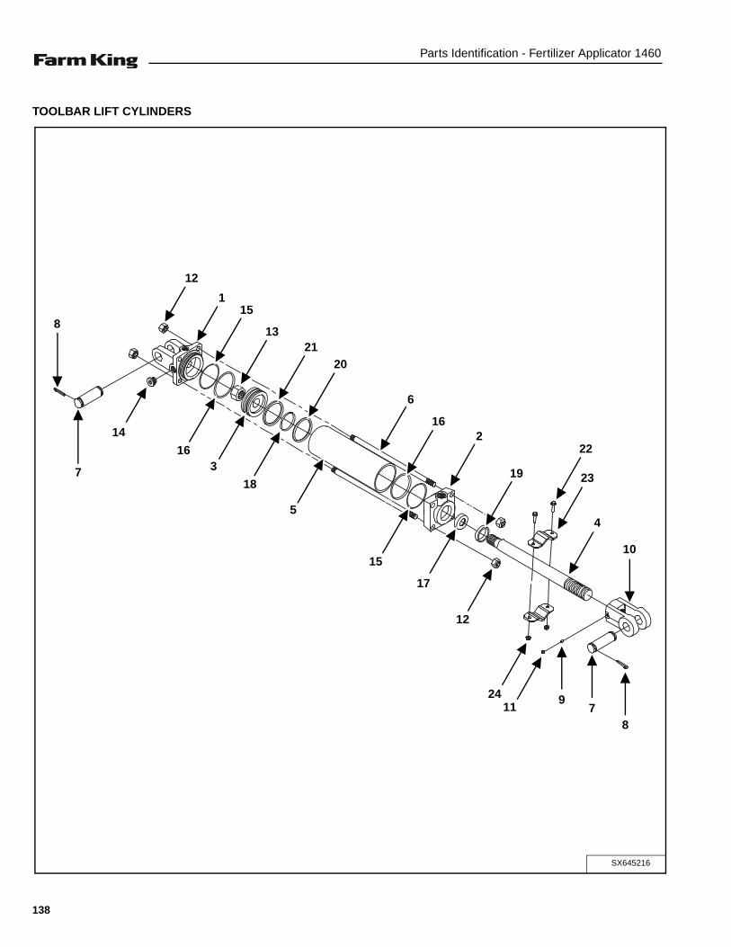
Parts Identification - Fertilizer Applicator 1460
TOOLBAR LIFT CYLINDERS
SX645216
1
12
14
8
7
15
13
163
21
18
20
5
6
16
15
2
17
19
12
4
11
10
97
8
22
23
24
138

Parts Identification - Fertilizer Applicator 1460
ITEM PART NUMBER DESCRIPTION QTY
1 SX492675 CLEVIS CAP 1
2 SX492728 ROD CAP 1
3 SX494719 PISTON 1
4 SX493597 CYLINDER ROD 1
5 SX491746 CYLINDER TUBE 1
6 SX492286 TIE ROD 4
7 SX134953 CYLINDER PIN 2
8 SX135995 PIN 4
9 SX498006 THREAD LOCK-NYLON 1
10 SX492652 ROD CLEVIS 1
11 SX148390 SOCKET SET SCREW, 3/8” UNC 1
12 SX125250 NUT, HEX (TIE ROD) 8
13 SX130560 NUT, HEX (CYL. ROD) 1
14 SX186562 PLUG, 3/4” - 16, SOC HD 1
* SX639558 SEAL REPAIR KIT 1
15 SEAL 2
16 O-RING 2
17 SEAL HALLITE 1
18 O-RING 1
19 SEAL NOK 1
20 SEAL PTFE PISTON RING 1
21 WEAR 1
22 SXBHF0381508YZ BOLT, 3/8” x 1.50” FLG GR 8 YLLW ZN 4
23 88669639 CYLINDER STOP PLATE 4
24 SXNTFTL038168YZ LOCKNUT, 3/8”-16 UNC FLG, TP LCK GR 8 YZ 4
* Seal Repair Kit includes Items 15 - 21 (Items not sold separately).
139

Parts Identification - Fertilizer Applicator 1460
INNER WING FOLD CYLINDERS
ITEM PART NUMBER DESCRIPTION QTY
1 88667541 PISTON ROD 1
2 88667542 TUBE 1
3 88667543 TIEROD ASSY 4
4 88667544 BUTT 1
5 88667545 GLAND 1
6 88667546 PISTON 1
7 88667547 CLEVIS ASSEMBLY 1
8 88667548 LOCKNUT, 1.25-12 1
9 SX6408-8 HYD FIT; 08 O-RING PLUG, SCKT 1
10 SXBHF0381508YZ BOLT, 3/8” x 1.50” FLG GR 8 YLLW ZN 4
11 88669639 CYLINDER STOP PLATE 4
12 SXNTFTL038168YZ LOCKNUT, 3/8”-16 UNC FLG, TP LCK GR 8 YZ 4
NS 88667491 SEAL REPAIR KIT 88667540 1
88667540 R AA
2
4
9
8
6
3
51
7
10
11
12
140

Parts Identification - Fertilizer Applicator 1460
RAVEN 450
ITEM PART NUMBER DESCRIPTION QTY1 SX063-0171-220 CONSOLE ASSY, 450 W/SERIAL PORT 12 SX115-0171-085 CABLE, RAVEN 450 CONTROL CABLE 13 88664958 CABLE, FLOW CONTROL 43 FT 6 SECT 1
SCS-450-2
2
1
3
141
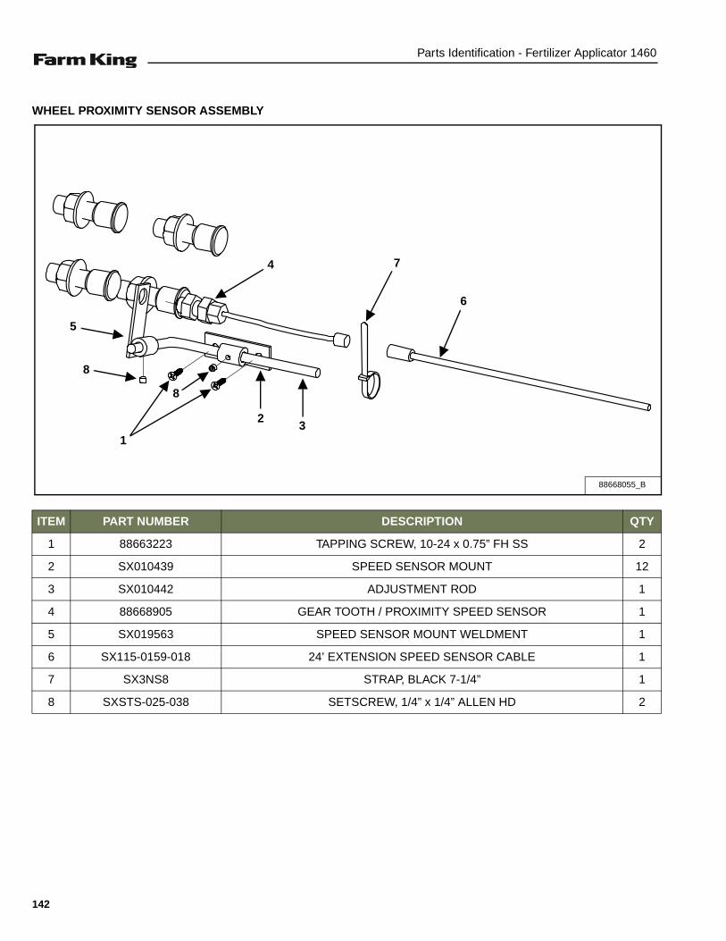
Parts Identification - Fertilizer Applicator 1460
WHEEL PROXIMITY SENSOR ASSEMBLY
ITEM PART NUMBER DESCRIPTION QTY
1 88663223 TAPPING SCREW, 10-24 x 0.75” FH SS 2
2 SX010439 SPEED SENSOR MOUNT 12
3 SX010442 ADJUSTMENT ROD 1
4 88668905 GEAR TOOTH / PROXIMITY SPEED SENSOR 1
5 SX019563 SPEED SENSOR MOUNT WELDMENT 1
6 SX115-0159-018 24’ EXTENSION SPEED SENSOR CABLE 1
7 SX3NS8 STRAP, BLACK 7-1/4” 1
8 SXSTS-025-038 SETSCREW, 1/4” x 1/4” ALLEN HD 2
88668055_B
5
8
1
8
2
4 7
6
3
142
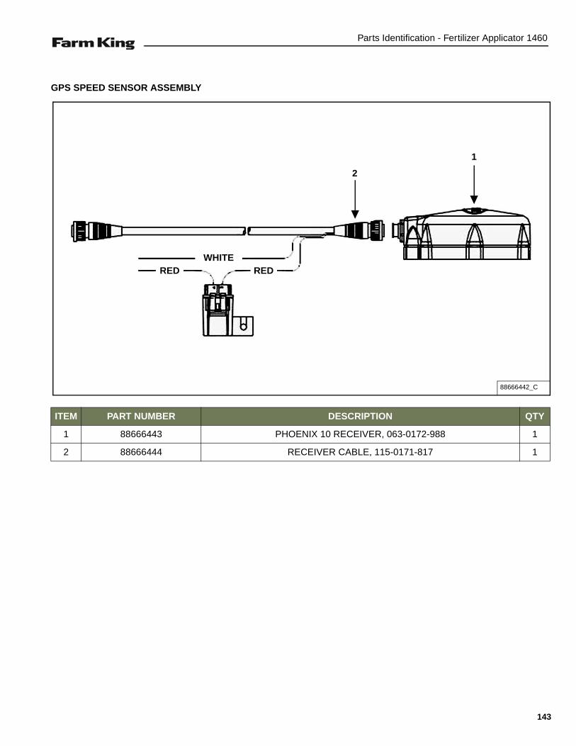
Parts Identification - Fertilizer Applicator 1460
GPS SPEED SENSOR ASSEMBLY
ITEM PART NUMBER DESCRIPTION QTY
1 88666443 PHOENIX 10 RECEIVER, 063-0172-988 1
2 88666444 RECEIVER CABLE, 115-0171-817 1
88666442_C
2
1
WHITEREDRED
143

Parts Identification - Fertilizer Applicator 1460
144

Specifications - Fertilizer Applicator 1460
SPECIFICATIONS
SPECIFICATIONS . . . . . . . . . . . . . . . . . . . . . . . . . . . . . . . . . . . . . . . . . . . . . . . . . . . . . . . . . . . . . 147Dimensions . . . . . . . . . . . . . . . . . . . . . . . . . . . . . . . . . . . . . . . . . . . . . . . . . . . . . . . . . . . . . . . . 147Performance . . . . . . . . . . . . . . . . . . . . . . . . . . . . . . . . . . . . . . . . . . . . . . . . . . . . . . . . . . . . . . . 147
HYDRAULIC SCHEMATIC . . . . . . . . . . . . . . . . . . . . . . . . . . . . . . . . . . . . . . . . . . . . . . . . . . . . . . . 148
ELECTRICAL SCHEMATIC . . . . . . . . . . . . . . . . . . . . . . . . . . . . . . . . . . . . . . . . . . . . . . . . . . . . . . 150
11R30 COULTER SPACING . . . . . . . . . . . . . . . . . . . . . . . . . . . . . . . . . . . . . . . . . . . . . . . . . . . . . 151
11R38 COULTER SPACING . . . . . . . . . . . . . . . . . . . . . . . . . . . . . . . . . . . . . . . . . . . . . . . . . . . . . 151
11R36 COULTER SPACING . . . . . . . . . . . . . . . . . . . . . . . . . . . . . . . . . . . . . . . . . . . . . . . . . . . . . 152
15R30 COULTER SPACING . . . . . . . . . . . . . . . . . . . . . . . . . . . . . . . . . . . . . . . . . . . . . . . . . . . . . 152
17R30 COULTER SPACING . . . . . . . . . . . . . . . . . . . . . . . . . . . . . . . . . . . . . . . . . . . . . . . . . . . . . 153
11R40 COULTER SPACING . . . . . . . . . . . . . . . . . . . . . . . . . . . . . . . . . . . . . . . . . . . . . . . . . . . . . 153
23R22 COULTER SPACING . . . . . . . . . . . . . . . . . . . . . . . . . . . . . . . . . . . . . . . . . . . . . . . . . . . . . 154
15R22 COULTER SPACING . . . . . . . . . . . . . . . . . . . . . . . . . . . . . . . . . . . . . . . . . . . . . . . . . . . . . 154
HARDWARE TORQUE VALUES . . . . . . . . . . . . . . . . . . . . . . . . . . . . . . . . . . . . . . . . . . . . . . . . . . 155Metric Chart . . . . . . . . . . . . . . . . . . . . . . . . . . . . . . . . . . . . . . . . . . . . . . . . . . . . . . . . . . . . . . . 155Imperial Chart . . . . . . . . . . . . . . . . . . . . . . . . . . . . . . . . . . . . . . . . . . . . . . . . . . . . . . . . . . . . . . 156
HYDRAULIC CONNECTION SPECIFICATIONS . . . . . . . . . . . . . . . . . . . . . . . . . . . . . . . . . . . . . .157O-Ring Fitting (Straight Thread) . . . . . . . . . . . . . . . . . . . . . . . . . . . . . . . . . . . . . . . . . . . . . . . .157O-ring Face Seal Connection . . . . . . . . . . . . . . . . . . . . . . . . . . . . . . . . . . . . . . . . . . . . . . . . . . 157Flare Fitting . . . . . . . . . . . . . . . . . . . . . . . . . . . . . . . . . . . . . . . . . . . . . . . . . . . . . . . . . . . . . . . . 157Port Seal (O-ring Boss) Fitting . . . . . . . . . . . . . . . . . . . . . . . . . . . . . . . . . . . . . . . . . . . . . . . . . 157Tubelines And Hoses . . . . . . . . . . . . . . . . . . . . . . . . . . . . . . . . . . . . . . . . . . . . . . . . . . . . . . . . 157
NOZZLE SELECTION . . . . . . . . . . . . . . . . . . . . . . . . . . . . . . . . . . . . . . . . . . . . . . . . . . . . . . . . . . 158Density Correction Chart . . . . . . . . . . . . . . . . . . . . . . . . . . . . . . . . . . . . . . . . . . . . . . . . . . . . . 158
NOZZLE SPECIFICATIONS . . . . . . . . . . . . . . . . . . . . . . . . . . . . . . . . . . . . . . . . . . . . . . . . . . . . . . 159
145

Specifications - Fertilizer Applicator 1460
146

Specifications - Fertilizer Applicator 1460
SPECIFICATIONS
Dimensions
Performance
DESCRIPTION 1460
Overall Field Height (A) 8 ft. 6 in.
Overall Field Width (B) 40 ft. 11 in.
Transport Width 16 ft. 5 in.
Transport Height 12 ft. 10 in.
Transport Length 23 ft. 6 in.
Pin To Axle 17 ft. 3 in.
NOTE: Dimensions are approximate measurements.
DESCRIPTION 1460
Product Tank 1600 U.S. gal.
Fresh Water Safety Tank 9 U.S. gal.
Pump Options Ace Hydraulic Driven Centrifugal Pump Kit with Raven 450 Console
John Blue Twin Piston Ground Drive Pump Kit
Toolbar Available in 20”, 22”, 30”, 36”, 38” & 40” row spacings up to 40 ft. wide.
Coulters 20 in. Ripple, Spring - Cushioned (Knives or Injectors)
Gauge Wheels 2
Tires Single Tire / Rim 380/90R48
Ground Clearance 17 in. in field operation, 42 in. on turn rows
Electrical Harness 7 - Pin
1460 DIM
A
B
Overall Field Dimensions
147

Specifications - Fertilizer Applicator 1460
HYDRAULIC SCHEMATIC
CB3
SV1
PC3
SV2
CB1 CB2
FD1 PS1
CV1
PR1
SCV 1 RETRACT
SCV 1 EXTEND
SCV 2 RETRACT
SCV 2 EXTEND
R.H. ROCK SHAFT CYL.
L.H. ROCK SHAFT CYL.
R.H. INNER WING FOLD CYL.
L.H. INNER WING FOLD CYL.
R.H. OUTER WING FOLD CYL.
L.H. OUTER WING FOLD CYL.
1460 HYD SCHEMATIC
148

Specifications - Fertilizer Applicator 1460
ITEM PART NUMBER DESCRIPTION QTYCB3 88661439 VALVE, C-BALANCE 2.5:1 RATIO 1
CB1 / CB2 88661440 VALVE, C-BALANCE 10.0:1 RATIO 2CV1 88661441 CHECK VALVE, #10 1FD1 88661442 FLOW DIVIDER, #10 COMBINER 1PC3 88661443 CHECK VALVE, #10 PILOT-OPEN 1PR1 88661444 PRESSURE REDUCING VALVE, #10 1PS1 88661445 SEQUENCE VALVE, #10 PILOT-DRAIN 1
SV1 / SV2 88661446 2-WAY POPPET SOLENOID, #10 N.O. 2SV1 / SV2 88661447 METRI-PACK, #10 150, 12 VDC, E-COIL 2
149

Specifications - Fertilizer Applicator 1460
ELECTRICAL SCHEMATIC
ELECTRICAL SCHEMATIC
150

Specifications - Fertilizer Applicator 1460
11R30 COULTER SPACING
11R38 COULTER SPACING
11R30
11R38
151

Specifications - Fertilizer Applicator 1460
11R36 COULTER SPACING
15R30 COULTER SPACING
11R36
11R30
152

Specifications - Fertilizer Applicator 1460
17R30 COULTER SPACING
11R40 COULTER SPACING
17R30
11R40
153

Specifications - Fertilizer Applicator 1460
23R22 COULTER SPACING
15R22 COULTER SPACING
23R22
15R22
154

Specifications - Fertilizer Applicator 1460
HARDWARE TORQUE VALUES
Metric Chart
NOTE: Do not use the values listed in the charts if a different torque value or tightening procedure is specifiedin this manual for a specific application. Torque values listed are for general use only.
Use the following charts to determine the correct torque when checking, adjusting or replacing hardware. Torquevalues are listed in newton-meters (inch* or foot pounds) for normal assembly applications.
Nominal Size
Class 5.8 Class 8.8 Class 10.9 Lock nuts
Unplated PlatedW / ZnCr
Unplated PlatedW / ZnCr
Unplated PlatedW / ZnCr
CL.8 w/CL. 8.8 Bolt
M4 1.7 (15*) 2.2 (19*) 2.6 (23*) 3.4 (30*) 3.7 (33*) 4.8 (42*) 1.8 (16*)
M6 5.8 (51*) 7.6 (67*) 8.9 (79*) 12 (102*) 13 (115*) 17 (150*) 6.3 (56*)
M8 14 (124*) 18 (159*) 22 (195*) 28 (248*) 31 (274*) 40 (354*) 15 (133*)
M10 28 (21) 36 (27) 43 (32) 56 (41) 61 (45) 79 (58) 30 (22)
M12 49 (36) 63 (46) 75 (55) 97 (72) 107 (79) 138 (102) 53 (39)
M16 121 (89) 158 (117) 186 (137) 240 (177) 266 (196) 344 (254) 131 (97)
M20 237 (175) 307 (226) 375 (277) 485 (358) 519 (383) 671 (495) 265 (195)
M24 411 (303) 531 (392) 648 (478) 839 (619) 897 (662) 1160 (855) 458 (338)
NOTE: Torque values shown with * are inch pounds.
Identification of Hex Cap Screws and Carriage Bolts - Classes 5 and up
XYZ
8 8
8 8ABCD
MANUFACTURER’S IDENTIFICATION
PROPERTY CLASS
Identification of Hex Nuts and Lock Nuts - Classes 5 and up
PROPERTY CLASS
MANUFACTURER’S IDENTIFICATION
PROPERTY CLASS
AB
AB8
8 AB
155

Specifications - Fertilizer Applicator 1460
HARDWARE TORQUE VALUES (CONT’D)
Imperial Chart
NOTE: Do not use the values listed in the charts if a different torque value or tightening procedure is specifiedin this manual for a specific application. Torque values listed are for general use only.
Use the following charts to determine the correct torque when checking, adjusting or replacing hardware. Torquevalues are listed in newton-meters (inch* or foot pounds) for normal assembly applications.
Nominal Size
SAE Grade 5 SAE Grade 8 LOCK NUTS
Unplatedor
Plated Silver
PlatedW / ZnCr
Gold
Unplatedor
Plated Silver
PlatedW / ZnCr
Gold
Unplatedor
Plated Silver
PlatedW / ZnCr
Gold
GradeW / Gr. 5
Bolt
GradeW / Gr. 8
Bolt
1/4 6.2 (55*) 8.1 (72*) 9.7 (86*) 12.6 (112*) 13.6 (121*) 17.7 (157*) 6.9 (61*) 9.8 (86*)
5/16 13 (115*) 17 (149*) 20 (178*) 26 (229*) 28 (250*) 37 (324*) 14 (125*) 20 (176*)
3/8 23 (17) 30 (22) 35 (26) 46 (34) 50 (37) 65 (48) 26 (19) 35 (26)
7/16 37 (27) 47 (35) 57 (42) 73 (54) 80 (59) 104 (77) 41 (30) 57 (42)
1/2 57 (42) 73 (54) 87 (64) 113 (83) 123 (91) 159 (117) 61 (45) 88 (64)
9/16 81 (60) 104 (77) 125 (92) 163 (120) 176 (130) 229 (169) 88 (65) 125 (92)
5/8 112 (83) 145 (107) 174 (128) 224 (165) 244 (180) 316 (233) 122 (90) 172 (127)
3/4 198 (146) 256 (189) 306 (226) 397 (293) 432 (319) 560 (413) 217 (160) 306 (226)
7/8 193 (142) 248 (183) 495 (365) 641 (473) 698 (515) 904 (667) 350 (258) 494 (364)
1 289 (213) 373 (275) 742 (547) 960 (708) 1048 (773) 1356 (1000) 523 (386) 739 (545)
NOTE: Torque values shown with * are inch pounds.
Identification of Hex Cap Screws and Carriage Bolts
Identification of Hex Nuts and Lock Nuts
SAE GRADE 2 BOLTS
SAE GRADE 5 BOLTS
SAE GRADE 8 BOLTS
SAE GRADE 2 NUTS
SAE GRADE 2 NUTS
SAE GRADE 2 NUTS
B
Grade A - No Notches
Grade B - One Circumferential Notch
Grade C - One Circumferential Notches
Grade A - No Mark
Grade B - Letter B
Grade C - Letter C
Grade A - No Marks
Grade B - Three Marks
Grade C - Six Marks
(Marks not always located at corners)
156

Specifications - Fertilizer Applicator 1460
HYDRAULIC CONNECTION SPECIFICATIONS
O-Ring Fitting (Straight Thread)
Lubricate the O-ring before installing the fitting. Loosenthe jam nut and install the fitting. Tighten the jam nut untilthe washer is tight against the surface.
O-ring Face Seal Connection
Figure 57
When the fitting is tightened, you can feel when the fittingis tight to eliminate leakage caused by under or overtorqued fittings. Use petroleum jelly to hold the O-ring inposition until the fittings are assembled [Figure 57].
Flare Fitting
Figure 58
Tighten until the nut makes contact with the seat. Use thechart [Figure 58] to find the correct tightness needed.
NOTE: If the fitting leaks, disconnect and inspect theseat area for damage.
Port Seal (O-ring Boss) Fitting
Figure 59
NOTE: Port seal and nut, washer and O-ring (O-ringBoss) fittings use the same tightening torquevalve chart [Figure 59].
If a torque wrench cannot be used, use the followingmethod.
Tighten the nut until it just makes metal to metal contact,you can feel the resistance.
Tighten the nut with a wrench no more than one hex flatmaximum.
Do not over tighten the port seal fitting.
NOTE: If a torque wrench cannot be used, use thehex flat tightening method as an approximateguideline.
NOTE: Port seal fittings are not recommended in allapplications. Use O-ring boss fittings in theseapplications.
Tubelines And Hoses
Replace any tubelines that are bent or flattened. They willrestrict flow, which will slow hydraulic action and causeheat.
Replace hoses which show signs of wear, damage orweather cracked rubber.
Always use two wrenches when loosening and tighteninghose or tubeline fittings.
O-ring Face Seal Tightening TorqueTubeline O.D. Thread Size N•m (ft-lb)
1/4” 9/16” - 18 13 (18)3/8” 11/16” - 16 22 (30)1/2” 13/16” - 16 40 (54)5/8” 1” - 14 60 (81)3/4” 1-3/16” - 12 84 (114)7/8” 1-3/16” - 12 98 (133)1” 1-7/16” - 12 118 (160)
1-1/4” 1-11/16” - 12 154 (209)
1-1/2” 2” - 12 163 (221)
Flare Fitting Tightening Torque
Tubeline O.D. Thread Size N•m (ft-lb)
1/4” 7/16” - 20 13 (18)
5/16” 1/2” - 20 17 (23)
3/8” 9/16” - 18 22 (30)
1/2” 3/4” - 16 40 (54)
5/8” 7/8” - 14 60 (81)
3/4” 1-1/16” - 12 84 (114)
7/8” 1-3/16” - 12 98 (133)
1” 1-5/16” - 12 118 (160)
1-1/4” 1-5/8” - 12 154 (209)
1-1/2” 1-7/8” - 12 163 (221)
2” 2-1/2” - 12 252 (342)
Port Seal And O-ring Boss Tightening Torque
Tubeline O.D. Thread Size N•m (ft-lb)
1/4” 7/16” - 20 13 (18)
3/8” 9/16” - 18 22 (30)
1/2” 3/4” -1 6 40 (54)
5/8” 7/8” - 14 60 (81)
3/4” 1-1/16” - 12 84 (114)
7/8” 1-3/16” - 12 98 (133)
1” 1-5/16” - 12 118 (160)
1-1/8” 1-7/16” - 12 154 (209)
1-1/4” 1-5/8” - 12 163 (221)
157

Specifications - Fertilizer Applicator 1460
NOZZLE SELECTION
Use the following formula to covert pounds per acre to gallons per minute (gpm):
EXAMPLE - The desired output is 100 lbs of nitrogen per acre. In order to get 100 lbs of nitrogen you need to apply357 lbs of 28% nitrogen solution per acre. 357 lbs per acre of a solution that weighs 10.65 lbs per gallon equals33.53 gallons per acre (GPA). Select a nozzle that will provide 33.53 GPA at your desired system pressure.
Density Correction Chart
Additional Useful Formula:
Spacing Correction Chart
WEIGHT OF SOLUTION PER GALLON
EXAMPLE SPECIFIC GRAVITY CONVERSION FACTOR
7.00 lb. 0.84 0.92
8.00 lb. 0.96 0.98
8.34 lb. Water 1.00 1.00
9.00 lb. 1.08 1.04
10.00 lb. 1.20 1.10
10.65 lb. 28% Nitrogen 1.28 1.13
11.00 lb. 7 - 27 - 7 Fertilizer 1.32 1.15
11.06 lb. 32% Nitrogen 1.33 1.15
11.40 lb. 10 - 34 - 0 Fertilizer 1.37 1.17
11.50 lb. 12 - 0 - 0 - 26 Fertilizer 1.38 1.17
11.60 lb. 11 - 37 - 0 Fertilizer 1.43 1.20
12.00 lb. 1.44 1.20
14.00 lb. 1.68 1.30
NOZZLE SPACING CONVERSION FACTOR
22 in. 1.36 GPA Target Conversion Factor= Corrected GPA36 in. 0.83
38 in. 0.79
Total lb. per acre = Target lb. per acre
of nitrogen Percent of nitrogen
Total lb. per acre = GPA
Pound per gallon
Total lb. per acre: 357 = 100
of nitrogen 0.28
357 = 33.53 GPA
10.65
GPM = GPA x MPH x W
(per nozzle) 5940
GPA = GPM (per nozzle) x 5940
MPH x W
MPH = Distance in feet x 60
Time in seconds x 88 W = Nozzle spacing in inches
Your nozzle spacing
Conversion Factor = Nozzle spacing in tableNOTE: For nozzle spacing not shown, use this formula:
158

Specifications - Fertilizer Applicator 1460
NOZZLE SPECIFICATIONS
* Nozzle or tip (TP). Tip used with the standard TeeJet® cap. Nozzles are threaded with BSPT threads.
** Use the conversion factor for other nozzle spacings.
NOZZLE* PSIGPM
(Per Nozzle)GPA AT 30” NOZZLE SPACING**
4 MPH 6 MPH 8 MPH 10 MPH
H1/4U - SS0004 10 0.20 9.9 6.6 5.0 4.020 0.28 13.9 9.2 6.9 5.530 0.35 17.3 11.6 8.7 6.940 0.40 19.8 13.2 9.9 7.9
H1/4U - SS0006 10 0.30 14.9 9.9 7.4 5.920 0.42 20.8 13.9 10.4 8.330 0.52 25.7 17.2 12.9 10.340 0.60 29.7 19.8 14.9 11.9
H1/4U - SS0008 10 0.40 19.8 13.2 9.9 7.920 0.57 28.2 18.8 14.1 11.330 0.69 34.2 22.8 17.1 13.740 0.80 39.6 26.4 19.8 15.8
H1/4U - SS0010 10 0.50 24.8 16.5 12.4 9.920 0.71 35.1 23.4 17.6 14.130 0.87 43.1 28.7 21.5 17.240 1.00 49.5 33.0 24.8 19.8
H1/4U - SS0015 10 0.75 37.1 24.8 18.6 14.920 1.06 52.5 35.0 26.2 21.030 1.30 64.4 42.9 32.2 25.740 1.50 74.3 49.5 37.1 29.7
H1/4U - SS0020 10 1.00 49.5 33.0 24.8 19.820 1.41 69.8 46.5 34.9 27.930 1.73 85.6 57.1 42.8 34.340 2.00 99.0 66.0 49.5 39.6
H1/4U - SS0030 10 1.50 74.3 49.5 37.1 29.720 2.12 104.9 70.0 52.5 42.030 2.60 128.7 85.8 64.4 51.540 3.00 148.5 99.0 74.3 59.4
H1/4U - SS0040 10 2.50 123.8 82.5 61.9 49.520 3.54 175.2 116.8 87.6 70.130 4.53 224.2 149.5 112.1 89.740 5.00 247.5 165.0 123.8 99.0
H1/4U - SS0050 10 3.00 148.5 99.0 74.3 59.420 4.24 209.9 139.9 104.9 84.030 5.20 257.4 171.6 128.7 103.040 6.00 297.0 198.0 148.9 84.0
H1/4U - SS0060 10 3.00 148.5 99.0 74.3 59.420 4.24 209.9 139.9 104.9 84.030 5.20 257.4 171.6 128.7 103.040 6.00 297.0 198.0 148.9 84.0
159

Specifications - Fertilizer Applicator 1460
160

Warranty - Fertilizer Applicator 1460
WARRANTY
WARRANTY . . . . . . . . . . . . . . . . . . . . . . . . . . . . . . . . . . . . . . . . . . . . . . . . . . . . . . . . . . . . . . . . . . 163
161

Warranty - Fertilizer Applicator 1460
162

Warranty - Fertilizer Applicator 1460
WARRANTY
Limited Warranty
BASE LIMITED WARRANTY
Farm King provides this warranty only to original retail purchasers of its products. Farm King warrants to suchpurchasers that all Farm King manufactured parts and components used and serviced as provided for in theOperator’s Manual shall be free from defects in materials and workmanship for a period following delivery tothe original retail purchaser of one (1) year. This limited warranty applies only to those parts and componentsmanufactured by Farm King. Parts and components manufactured by others are subject to theirmanufacturer’s warranties, if any.
Farm King will fulfill this limited warranty by, at its option, repairing or replacing any covered part that isdefective or is the result of improper workmanship, provided that the part is returned to Farm King within thirty(30) days of the date that such defect or improper workmanship is, or should have been, discovered. Partsmust be returned through the selling representative and the buyer must prepay transportation charges.
Farm King will not be responsible for repairs or replacements that are necessitated, in whole or part, by theuse of parts not manufactured by or obtained from Farm King. Under no circumstances are component partswarranted against normal wear and tear. There is no warranty on product pump seals, product pump bearings,rubber product hoses, pressure gauges, or other components that require replacement as part of normalmaintenance.
REPAIR PARTS LIMITED WARRANTY
Farm King warrants genuine Farm King replacement parts purchased after the expiration of the Farm KingLimited Warranty, and used and serviced as provided for in the Operator’s Manual, to be free from defects inmaterials or workmanship for a period of thirty (30) days from the invoice date for the parts. Farm King willfulfill this limited warranty by, at its option, repairing or replacing any covered part that is defective or is theresult of improper workmanship, provided that the part is returned to Farm King within thirty (30) days of thedate that such defect or improper workmanship is, or should have been, discovered. Such parts must beshipped to the Farm King factory at the purchaser’s expense.
WHAT IS NOT COVERED
Under no circumstances does this limited warranty cover any components or parts that have been subject tothe following: negligence; alteration or modification not approved by Farm King; misuse; improper storage;lack of reasonable and proper maintenance, service, or repair; normal wear; damage from failure to followoperating instructions; accident; and/or repairs that have been made with parts other than thosemanufactured, supplied, and or authorized by Farm King.
AUTHORIZED DEALER AND LABOR COSTS
Repairs eligible for labor under this limited warranty must be made by Farm King or an authorized Farm Kingdealer. Farm King retains the exclusive discretion to determine whether it will pay labor costs for warrantyrepairs or replacements, and the amount of such costs that it will pay and the time in which the repairs will bemade. If Farm King determines that it will pay labor costs for warranty work, it will do so by issuing a credit tothe dealer’s or distributor’s account. Farm King will not approve or pay invoices sent for repairs that Farm Kinghas not previously approved. Warranty service does not extend the original term of this limited warranty.
163

Warranty - Fertilizer Applicator 1460
Limited Warranty
WARRANTY REQUIREMENTS
To be covered by warranty, each new product must be registered with Farm King within thirty (30) days ofdelivery to original retail purchaser. If the customer decides to purchase replacement components before thewarranty disposition of such components is determined, Farm King will bill the customer for suchcomponents and then credit the replacement invoice for those components later determined to be covered bythis limited warranty. Any such replacement components that are determined not be covered by this limitedwarranty will be subject to the terms of the invoice and shall be paid for by the purchaser.
EXCLUSIVE EFFECT OF WARRANTY AND LIMITATION OF LIABILITY
TO THE EXTENT PERMITTED BY LAW, FARM KING DISCLAIMS ANY WARRANTIES, REPRESENTATIONS, ORPROMISES, EXPRESS OR IMPLIED, AS TO THE QUALITY, PERFORMANCE, OR FREEDOM FROM DEFECT OFTHE COMPONENTS AND PARTS COVERED BY THIS WARRANTY AND NOT SPECIFICALLY PROVIDED FORHEREIN.
TO THE EXTENT PERMITTED BY LAW, FARM KING DISCLAIMS ANY IMPLIED WARRANTIES OFMERCHANTABILITY AND FITNESS FOR A PARTICULAR PURPOSE ON ITS PRODUCTS COVERED HEREIN,AND DISCLAIMS ANY RELIANCE BY THE PURCHASER ON FARM KING’S SKILL OR JUDGMENT TO SELECTOR FURNISH GOODS FOR ANY PARTICULAR PURPOSE. THE PURCHASER’S ONLY AND EXCLUSIVEREMEDIES IN CONNECTION WITH THE BREACH OR PERFORMANCE OF ANY WARRANTY ON FARM KING’SPRODUCTS ARE THOSE SET FORTH HEREIN. IN NO EVENT SHALL FARM KING BE LIABLE FOR INCIDENTALOR CONSEQUENTIAL DAMAGES (INCLUDING, BY WAY OF EXAMPLE ONLY AND NOT LIMITATION, LOSS OFCROPS, LOSS OF PROFITS OR REVENUE, OTHER COMMERCIAL LOSSES, INCONVENIENCE, OR COST OFREPLACEMENT OF RENTAL EQUIPMENT). IN NO EVENT SHALL FARM KING’S CONTRACT OR WARRANTYLIABILITY EXCEED THE PURCHASE PRICE OF THE PRODUCT. (Note that some states do not allow limitationson how long an implied warranty lasts or the exclusion or limitation of incidental or consequential damages,so the above limitations and exclusion may not apply to you.) This warranty gives you specific legal rights andyou may also have other rights, which vary from state to state.
Farm King neither assumes nor authorizes any person or entity, including its selling representatives, toassume any other obligations or liability in connections with the sale of covered equipment, or to make anyother warranties, representations, or promises, express or implied, as to the quality, performance, or freedomfrom defect of the components and parts covered herein. No one is authorized to alter, modify, or enlarge thislimited warranty, or its exclusions, limitations and reservations.
Corrections of defects and improper workmanship in the manner, and for the applicable time periods, providedfor herein shall constitute fulfillment of all responsibilities of Farm King to the purchaser, and Farm King shallnot be liable in negligence, contract, or on any other basis with respect to the subject equipment.
This limited warranty is subject to any existing conditions of supply which may directly affect Farm King’sability to obtain materials or manufacturer replacement parts.
Buhler Industries Inc. reserves the right to make improvements in design or changes in specifications to itsproducts at anytime, without incurring any obligation to owners of units previously sold.
164

Alphabetical Index - Fertilizer Applicator 1460
ALPHABETICAL INDEX
11R30 COULTER SPACING . . . . . . . . . . . 15111R36 COULTER SPACING . . . . . . . . . . . 15211R38 COULTER SPACING . . . . . . . . . . . 15111R40 COULTER SPACING . . . . . . . . . . . 15315R22 COULTER SPACING . . . . . . . . . . . 15415R30 COULTER SPACING . . . . . . . . . . . 15217R30 COULTER SPACING . . . . . . . . . . . 15323R22 COULTER SPACING . . . . . . . . . . . 154ACE CENTRIFUGAL PUMP & PLUMBING ASSEMBLY (OPTION) . . . . . . . . . . . . . . . . 104ADJUSTABLE AXLE . . . . . . . . . . . . . . . . . . 83ADJUSTING HYDRAULIC PRESSURE . . . . 72AXLES . . . . . . . . . . . . . . . . . . . . . . . . . . . . . 75CLEANING . . . . . . . . . . . . . . . . . . . . . . . . . . 77COMPONENT INSTALLATION . . . . . . . . . . 29COULTER ARM ASSEMBLY . . . . . . . . . . . 126COULTER ASSEMBLY (STRAIGHT) . . . . . 122COULTER CLAMP KIT (4X6 BAR) . . . . . . 128COULTER HOSE ASSEMBLY . . . . . . . . . . 129COULTER W / INJECTOR GROUP . . . . . . 120COULTER W / KNIFE GROUP . . . . . . . . . 118ELECTRICAL HARNESSES / ROUTING . 134ELECTRICAL SCHEMATIC . . . . . . . . . . . . 150EQUIPMENT DECALS AND SIGNS . . . . . . 24EQUIPMENT IDENTIFICATION . . . . . . . . . . 10FERTILIZER APPLICATOR OPERATION . . 50FIELD OPERATION . . . . . . . . . . . . . . . . . . . 59FIRE PREVENTION . . . . . . . . . . . . . . . . . . . 18FRAME ASSEMBLY . . . . . . . . . . . . . . . . . . . 86GAUGE WHEEL GROUP LH / RH . . . . . . . 130GAUGE WHEEL HUB ASSEMBLY (256 - 6 - 6 - 4.62) . . . . . . . . . . . . . . . . . . . . . . . . . . . . . . 131GENERAL INFORMATION . . . . . . . . . . . . . 43GENERAL PARTS INFORMATION . . . . . . . 83GPS SPEED SENSOR ASSEMBLY . . . . . 143HAND / EYE RINSE TANK ASSEMBLY . . . 103HAND RINSE TANK ASSEMBLY . . . . . . . . 102HARDWARE TORQUE VALUES . . . . . . . . 155
HYDRAULIC CONNECTION SPECIFICATIONS . . . . . . . . . . . . . . . . . . . 157HYDRAULIC MANIFOLD BLOCK (W / OUTER WINGS) . . . . . . . . . . . . . . . . . . . . . . . . . . . .98HYDRAULIC MANIFOLD BLOCK (W/O OUTER WINGS) . . . . . . . . . . . . . . . . . . . . . . 96HYDRAULIC PLUMBING ASSEMBLY (W / OUTER WINGS) . . . . . . . . . . . . . . . . . . . . . . 94HYDRAULIC PLUMBING ASSEMBLY (W/O OUTER WINGS) . . . . . . . . . . . . . . . . . . . . . . 92HYDRAULIC SCHEMATIC . . . . . . . . . . . . . 148INITIAL SET-UP . . . . . . . . . . . . . . . . . . . . . . 46INNER WING FOLD CYLINDERS . . . . . . . 140JOHN BLUE GROUND DRIVE MOUNT ASSEMBLY . . . . . . . . . . . . . . . . . . . . . . . . . 108JOHN BLUE PUMP SETTING . . . . . . . . . . . 49JOHN BLUE TWIN PUMP ASSEMBLY . . . 110LIGHTING MARKING GROUP . . . . . . . . . . 132LUBRICATION . . . . . . . . . . . . . . . . . . . . . . . 70MICROSWITCH . . . . . . . . . . . . . . . . . . . . . 117NOZZLE SELECTION . . . . . . . . . . . . . . . . 158NOZZLE SPECIFICATIONS . . . . . . . . . . . . 159OUTER WING FOLD CYLINDERS . . . . . . 136OWNER’S INFORMATION . . . . . . . . . . . . . . . 9PINTLE HITCH ASSEMBLY . . . . . . . . . . . . . 84RAVEN 450 . . . . . . . . . . . . . . . . . . . . . . . . 141RAVEN CONTROL PLUMBING ASSEMBLY . .112RUNNING GEAR HUB ASSEMBLY (11.25BC, 15000#) . . . . . . . . . . . . . . . . . . . . . . . . . . .135SAFETY INSTRUCTIONS . . . . . . . . . . . . . . 15SAFETY SIGN (DECAL) INSTALLATION . . . 78SAFETY SIGN-OFF FORM . . . . . . . . . . . . . 25SAFETY SIGNS (DECALS) . . . . . . . . . . . . . 21SERVICE SCHEDULE . . . . . . . . . . . . . . . . . 69SINGLE COLUMN MONITOR ASSEMBLY 116SPECIFICATIONS . . . . . . . . . . . . . . . . . . . 147SPRAY MONITORS . . . . . . . . . . . . . . . . . . 114STORAGE AND RETURN TO SERVICE . . . 79TANK AND PLUMBING ASSEMBLY . . . . . 100
165

Alphabetical Index - Fertilizer Applicator 1460
TANK QUICK FILL PLUMBING ACE CENTRIFUGAL PLUMBING ASSEMBLY . 106TOOLBAR ASSEMBLY (431.31 IN.) . . . . . . 88TOOLBAR ASSEMBLY (491.31 IN.) . . . . . . 90TOOLBAR LIFT CYLINDERS . . . . . . . . . . 138TRANSPORTING . . . . . . . . . . . . . . . . . . . . . 64TROUBLESHOOTING . . . . . . . . . . . . . . . . . 67WARRANTY REGISTRATION FORM . . . . . . 5WARRANTY . . . . . . . . . . . . . . . . . . . . . . . . 163WHEEL PROXIMITY SENSOR ASSEMBLY . .142
166


2500 Airport Drive SWWillmar, MN USA 56201Toll Free: 1-888-FK-80001 E-mail: [email protected]
Equipment shown is subject to change without notice.©2016 Buhler Trading Inc. Printed in Canada TSX:BUI
www.farm-king.com