ferronics 2002 pages(rev) · design considerations ferrite toroids provide an often convenient and...
TRANSCRIPT
Ferronics Incorporated
is totally dedicated
to the principle of
continuous quality
improvement in all areas
of our operation
as a means of providing
long term satisfaction
to the users of our products.
This policy is based on each
employee understanding
the full requirements of
our customers, and
being committed to
supplying nothing less than
the best possible products
and services.
Quality Policy
1

Company Profile
Quality is the cornerstone of our existenceFerronics Inc. is a U.S. based manufacturer of ferritecomponents and assemblies used in the computer, CATV,telecommunications, and other related electronics indus-tries. Founded in 1968, the company is headquartered inmodern, newly constructed manufacturing facilitieslocated in Fairport, New York.
Ferronics manufactures ferrite components in severalshapes, such as toroids, beads, baluns and multi-holecores, as well as in a variety of sizes. The company alsooffers custom manufacturing of ferrite parts and woundcomponents that are designed and finished according toexact customer needs and specifications.
Targeting both commercial and industrial markets,Ferronics sells its products to original equipment manu-facturers who use the components as inductors, chokes,and transformers in televisions, CATV taps and peripheraldevices. In addition to a strong sales base in NorthAmerica, Ferronics also serves overseas markets inEurope, South America, and the Far East. The companysells its products through manufacturer representativesas well as through Dexter Magnetic Technologies, aninternational stocking distributor.
At Ferronics, we realize that an operational philosophydriven by quality is the best way we can provide longterm satisfaction to the users of our products. A dedica-tion to quality permeates everything we do and governsour relationships with suppliers and customers. In eachstep of the manufacturing and testing process atFerronics, concern for quality is the guiding principle.We wouldn’t have it any other way.
The building blocks for today’s eletronics industryThe electronics industry as we know it today could notexist without the widespread use of ferrites. The term“ferrite” is derived from the Latin word “ferrum”, mean-ing iron. Ferrites are homogeneous ceramic materialscomposed of various oxides containing iron oxide astheir main constituent. Being ceramic, ferrites are hard,inert, and free of organic substances. What makes ferrites especially useful in the electronics industry is acombination of two key characteristics: (1) high mag-netic permeability which concentrates and reinforces themagnetic field and (2) high electrical resistivity whichlimits the amount of electric current flow in the ferrite.Thanks to these two characteristics, ferrites exhibit lowenergy losses, are highly efficient, and function at highfrequencies (1 KHz to 1,000 MHz). These qualities makeferrites ideal building blocks in the manufacture ofminiaturized high frequency electronic components.
Ferrites can be used in an ever widening range of electronic applications. Some of the more commonapplications include the following:
Magnetic DevicesPower transformers and chokesInductors and tuned transformersPulse and wide band transformersMagnetic deflectionRecording headsRotating transformersShield beads and chokesTransducers
ApplicationsHF Power suppliesFrequency selective circuitsMatching devicesTV sets and monitorsStorage devicesVCRsInterference suppressionVending machinesDatacomTelecomGame machines - Consumer & Commercial
2

Glossary of Terms
Ferronics soft ferrite products are made from both manganese-zinc and nickel-zinc materials, with a widerange of capabilities. The glossary of terms below definesthe salient characteristics used to describe the variousmaterials, and the Material Properties Table defines theparameters of each of Ferronics’ seven materials.
The following pages provide some representative materialcurves further defining the characteristics of the variousmaterials. Ferronics B,T and V materials (MnZn) are primarily used for frequencies below 2 MHz, and offerhigh initial permeability, low losses, and high saturationflux density. The rest of Ferronics’ materials, e.g., G, J,K, & P (all NiZn) provide high resistivity, and operate ina range from 1 MHz to several hundred MHz.
Amplitude Permeability, µa. The quotient of the peakvalue of flux density and peak value of applied fieldstrength at a stated amplitude of either, with no staticfield present.
Coercive Force, Hc (A/m).The magnetizing field strengthrequired to bring the magnetic flux density of a magnetized material to zero.
Curie Temperature, Tc (°C).The transition temperatureabove which a ferrite loses its ferrimagnetic properties.
Effective Dimensions of a Magnetic Circuit, Area Ae(cm2), Path Length le(cm), and Volume Ve (cm3). For amagnetic core of given geometry, the magnetic pathlength, the cross sectional area and the volume that ahypothetical toroidal core of the same material properties should possess to be the magnetic equivalentto the given core.
Effective Permeability, µe. For a magnetic circuit constructed with an air gap or air gaps, the permeabilityof a hypothetical homogeneous material which wouldprovide the same reluctance.
Field Strength, H (A/m). The parameter characterizingthe amplitude of alternating field strength.
Flux Density, B (Tesla). The corresponding parameter forthe induced magnetic field in an area perpendicular tothe flux path.
Incremental Permeability, µ∆. Under stated conditionsthe permeability obtained from the ratio of the flux density and the applied field strength of an alternatingfield and a super-imposed static field.
Inductance Factor, AL (nH). Inductance of a coil on a specified core divided by the square of the number of turns. (Unless otherwise specified, the inductance test conditions for inductance factor are at a flux density 1mT).
Initial Permeability, µ i. The permeability obtained fromthe ratio of the flux density, kept at 1mT, and therequired applied field strength. Material initially in aspecified neutralized state.
Loss Factor, tan δ/µ i. The phase displacement betweenthe fundamental components of the flux density and thefield strength divided by the initial permeability.
Magnetically Soft Material. A magnetic material with alow coercivity.
Magnetic Hysteresis. In a magnetic material, the irre-versible variation of the flux density or magnetizationwhich is associated with the change of magnetic fieldstrength and is independent of the rate of change.
Power Loss Density, P (mW/cm3). The power absorbedby a body of ferromagnetic material and dissipated asheat, when the body is subjected to an alternating fieldwhich results in a measurable temperature rise. The totalloss is divided by the volume of the body.
Remanence, Br (Tesla). The flux density remaining in amagnetic material when the applied magnetic fieldstrength is reduced to zero.
Saturation Flux Density, Bs (Tesla). The maximumintrinsic induction possible in a material.
3

Material Properties
4
CHARACTERISTIC V T B G J K* P* UNITS
Initial Permeability (µi) 15,000 10,000 5000 1500 850 125 40
Loss Factor (tan δ/µi) ≤ 7 ≤ 7 ≤ 15 60 150 85 X 10-6
at frequency = 0.01 0.01 0.1 0.1 0.1 10 10 MHz
Hysteresis Factor (h/µ2) - - < 2 10 6 - - X 10-6
Saturation Flux Density (Bs) 370 380 450 320 280 320 215 mTesla
3700 3800 4500 3200 2800 3200 2150 Gauss
at H max= 1000 1000 1000 1000 1000 2000 2000 A/m
12.6 12.6 12.6 12.6 12.6 25 25 Oersted
Remanence (Br) 150 140 100 150 180 160 40 mTesla
1500 1400 1000 1500 1800 1600 400 Gauss
Coercivity (Hc) 2.4 3.2 5.6 19.9 31.8 119 278 A/m
0.03 0.04 0.07 0.25 0.4 1.5 3.5 Oersted
Curie Temperature (Tc)** ≥ 120 ≥ 120 ≥ 165 ≥ 130 ≥ 140 ≥ 350 ≥ 350 °C
Temperature Coefficient of µi 0.8 0.8 0.9 1.0 1.0 0.1 0.1 %/°C
Volume Resistivity (p) 25 40 ≥ 102 ≥ 106 ≥ 105 ≥ 107 ≥ 106 Ω-cm
(α) -40°C to +80°C (T.C.)
*In K and P materials, permeability and loss factor will irreversibly increase ifexcited with high magnetizing force. This should be considered when applyingDC or high AC currents for test purposes.
**Consult factory for newest curie temperature update.
All values are typical and measured at 25°C except as noted.
The above quoted properties are typical values on commercially availableMnZn and NiZn ferrites.
FERRITE MATERIAL CONSTANTS
Specific heat .25 cal/g/°C
Thermal conductivity 10 10-3 cal/sec/cm/°C
Coefficient of linear expansion 8-10 10-6/°C
Tensile strength 7 103 lbs/in2
Compressive strength 60 103 lbs/in2
Youngs modulus 18 106 lbs/in2
Hardness (Knoop) 650
CONVERSION TABLE
1 T (Tesla) = 1 Vs/m2 = 104 gauss
1 mT = 10 gauss
1 A/m = 10-2 A/cm = .01257 oersted
.1 mT = 1 gauss
79.55 A/m = 1 oersted

Material Properties
V MATERIAL (15,000µi) is a manganese-zinc ferritecharacterized by high permeability with improved stability over temperature suitable for wide band filterand pulse applications.
5
FLUX DENSITY - mTesla
Material Properties
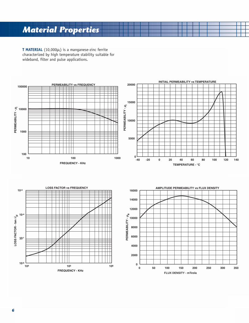
T MATERIAL (10,000µi) is a manganese-zinc ferritecharacterized by high temperature stability suitable forwideband, filter and pulse applications.
6
FLUX DENSITY - mTesla
10-5
Material Properties
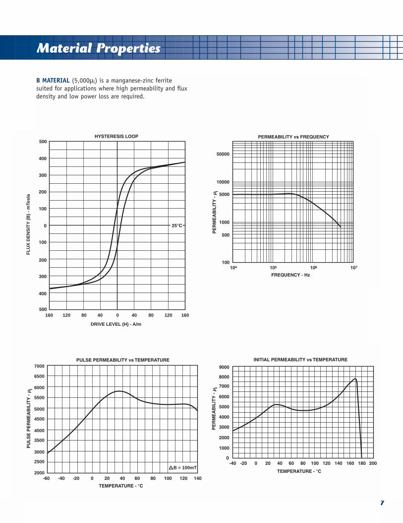
B MATERIAL (5,000µi) is a manganese-zinc ferrite suited for applications where high permeability and fluxdensity and low power loss are required.
7
FL
UX
DE
NS
ITY
(B
) -
mTe
sla
DRIVE LEVEL (H) - A/m
160 120 80 40 0 40 80 120 160
7000
6000
5000
4000
3000
2000
6500
5500
4500
3500
2500B = 100mT

10 100 1000
B (mTesla)
0.1 1 10 100
DC FIELD - H(A/m)
FL
UX
DE
NS
ITY
(B
) -
mTe
sla
600
550
500
450
400
350
300
250
200
150
100
50
0
Hmax = 160 A/m
FLUX DENSITY - mTesla
7000
Material Properties
B MATERIAL
8

Material Properties
G MATERIAL (1,500µi) is a nickel-zinc ferrite withhigh permeability which allows for reduced core sizeenhancing high frequency performance in widebandapplications.
9
J MATERIAL (850µi) is a nickel-zinc ferrite useful at higher frequencies where high resistivity accounts forlow eddy current losses. This makes it well suited fortransformers and inductors operating above 500KHz and
in particular for wideband devices above 5 MHz. It isalso effective in 20 to 500 MHz noise suppression applications.

Material Properties
K MATERIAL (125µi) is a cobalt-nickel ferrite suited forhigher frequency applications where low losses above2MHz are required.
10
P MATERIAL (40µi) is a cobalt-nickel-zinc ferritesuited for the highest frequency applications where lowlosses above 10 MHz are required.

Design Considerations
Ferrite toroids provide an often convenient and veryeffective shape for many wide band, pulse and powertransformers and inductors. The continuous magneticpath yields the highest effective permeability and lowestflux leakage of any shape.
Basic considerations:The inductance may be calculated from:
(the units are in CGS system which is used throughoutthis catalog). Here le and Ae are the effective magneticpath length and cross sectional area of the core, µ is theeffective permeability of the material, and N is the number of turns. This formula may be used for any shapeunder all conditions provided the correct value of µ isused and stray reactances are given proper consideration.In a toroidal core, this may be expressed as:
where OD, ID and H are the dimensions in inches. Forlow level conditions at comparatively low frequencies theformula may be simplified by using the InductanceIndex, AL, listed in this catalog. Then:
The other value most frequently needed is peak flux density, which may be calculated from:
Here E is the RMS voltage, 4.44 is a constant dependingon the wave shape (use 4 when E is a symmetricalsquare wave and 1 where E is a unipolar pulse), and f isthe frequency in hertz.
LOW LEVEL INDUCTORS:This section considers those applications where nonlinearity and losses due to hysteresis are negligible.Generally this means flux densities below a few hundredGauss. The first material choice is the one having boththe highest permeability and lowest loss factor, tan δ/µ,at the operating frequency. Considering the space available, select a core from the table and, using its
inductance index, AL, calculate the number of turnsrequired to give the desired inductance. Now select thelargest practical wire size that will fit on the core. Thisis somewhat difficult for a toroid, but generally the totalwire cross section in the winding can be 30-60% of thewindow opening. If there are Q or loss requirements cal-culate the resistance of the winding, taking into consid-eration the skin effect if the frequency is high, and addit to the equivalent series resistance contributed by thecore losses. Equation 5 shows the relationship betweenloss factor, Q and resistance.
If the calculated Q is inadequate you must reduce thetotal series resistance by selecting a larger core that willallow fewer turns of larger wire, select a less lossy material, or use Litz wire at high frequencies to minimizethe skin effect.
If losses are critical it is important to remember thathysteresis losses have been assumed to be negligible.Above mTesla these losses are measurable and increaseas approximately the 2.5 power of flux density. Also,remember that ferrites like other magnetic materialsshow variation in inductance from part to part, withtemperature and with magnetizing force. Unlike pow-dered metals which have air gaps between the particles a ferrite toroid is a continuous magnetic material withvariability effects undiluted by air gaps. This means thattight tolerances such as required for wave filters are notattainable in a toroid, but will generally require agapped structure such as an E core, pot core, or slug.
POWER INDUCTORS:In this section we consider inductors where the design islimited by saturation or heating due to core or windinglosses. Although there is no systematic connectionbetween permeability and losses, below about 1 MHz relatively high permeability manganese-zinc ferrites havethe most desirable combination of high saturation fluxdensity and low hysteresis losses. The first step is toselect one of those materials having the desired proper-ties (usually B material) and select a core based onspace limitations. Then select a suitable operating fluxdensity. As a general rule, at room temperature materialsmay be operated to the knee of the BH loop when thefrequency is 20 kHz or less. At higher frequencies hysteresis losses produce enough heat to require that the flux density be decreased. As a first approximation,the product of flux density and frequency can be held constant above 20 kHz. Knowing the voltage, frequency,flux density and area of the chosen core the minimumnumber of turns may be calculated from equation 4. 11
TOROIDS
1
2
3
5
4 mTesla7
Design Considerations
The inductance can then be estimated from equation 3or calculated more exactly from equations 1 or 2 byusing the appropriate value of permeability under theseoperating conditions. If this inductance is less than thedesired value, the number of turns can be adjustedupward provided there is sufficient space for the wind-ing. If the inductance is too great it will be necessary tochoose a larger core whose cross sectional area is greaterbut whose ratio of Ae/le is less, or a material with lowerpermeability.
For inductors operating above 1 MHz, the materialchoice becomes more difficult since other requirementssuch as return loss may be more important. The materialchoice and design procedure will depend on which factors predominate in your particular design. Inductorshaving dc current superimposed on the ac excitationmust be given special treatment. The magnetizing forcemay be calculated using equation 6:
With this information it is possible to estimate from theBH curves how significant will be the effect of the dccurrent. Generally dc magnetizing forces less the coerciveforce will have only a small effect on permeability, moderate values will depress the permeability, and magnetizing forces approaching the knee of the BH loopwill considerably reduce the permeability and severelylimit the peak flux density available for ac excitation. In these cases, unless a higher inductance can be used it will be necessary to go to a core with a considerablylonger magnetic path length or to provide an air gapsuch as by slotting the core.
In many power applications thermal considerationscontrol the design. One rule of thumb that may be usefulfor first approximations is that core losses of 100 to 600mW/cm3 produce an approximate 40° C temperature rise.The exact value depends on inductor geometry and ther-modynamic considerations beyond the scope of thisguide. You must also consider the power dissipated inthe winding and its contribution to inductor heating.Heat sinking or coolants may be used to remove thisheat, but the thermal conductivity of ferrite is relativelylow, so the interior core temperature will be higher.Should a large temperature gradient develop, the coremay crack from thermal stresses. Also, where consider-able temperature excursions occur due either to selfheating or ambient temperatures, the effect of thesechanges must also be considered with respect to changesin saturation flux density and inductance.
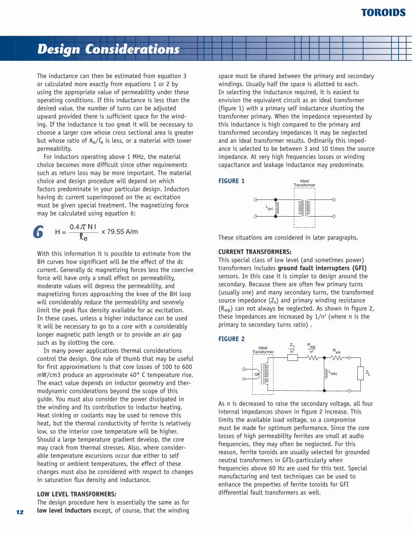
LOW LEVEL TRANSFORMERS:The design procedure here is essentially the same as forlow level inductors except, of course, that the winding
space must be shared between the primary and secondarywindings. Usually half the space is allotted to each. In selecting the inductance required, it is easiest to envision the equivalent circuit as an ideal transformer(figure 1) with a primary self inductance shunting thetransformer primary. When the impedance represented bythis inductance is high compared to the primary andtransformed secondary impedances it may be neglectedand an ideal transformer results. Ordinarily this imped-ance is selected to be between 3 and 10 times the sourceimpedance. At very high frequencies losses or windingcapacitance and leakage inductance may predominate.
FIGURE 1
These situations are considered in later paragraphs.
CURRENT TRANSFORMERS:This special class of low level (and sometimes power)transformers includes ground fault interrupters (GFI)sensors. In this case it is simpler to design around thesecondary. Because there are often few primary turns(usually one) and many secondary turns, the transformedsource impedance (Zs) and primary winding resistance(Rwp) can not always be neglected. As shown in figure 2,these impedances are increased by 1/n2 (where n is theprimary to secondary turns ratio) .
FIGURE 2
As n is decreased to raise the secondary voltage, all fourinternal impedances shown in figure 2 increase. This limits the available load voltage, so a compromise must be made for optimum performance. Since the corelosses of high permeability ferrites are small at audiofrequencies, they may often be neglected. For this reason, ferrite toroids are usually selected for groundedneutral transformers in GFIs-particularly when frequencies above 60 Hz are used for this test. Specialmanufacturing and test techniques can be used toenhance the properties of ferrite toroids for GFI differential fault transformers as well.
12
TOROIDS
6 x 79.55 A/m

Design Considerations
POWER TRANSFORMERS:Here we are considering the same kinds of situations wecovered under power inductors, that is, those caseswhere the design is limited by saturation flux density orself heating due to core and winding losses. At low frequencies, say below 1 MHz, the design procedure isthe same as that for power inductors except, of course,that winding space must be allowed for both windings.Ordinarily allot half each to the primary and secondary,or with a push-pull primary, slightly less than one thirdto each primary half. In most cases the voltage and frequency are known (use the lowest operating frequencyfor design purposes). Select a material and flux densityin the same manner as for power inductors. Then usingequation 4, calculate the product of Ae and N required.It is then a simple matter to go down the list of suitablecore sizes substituting for Ae, calculating the minimumnumber of turns required and checking the fit of thewinding in that core. Calculating the primary inductancefrom equations 1, 2, or 3, you will ordinarily find thatthe inductance will be large enough that the magnetiz-ing current may be neglected under full load. (This is thecurrent drawn by the primary inductance which shuntsthe ideal transformer.) The rest of the transformer designis fairly straight-forward and is covered in other publications. Most devices of this type are limited byeither saturation or heat dissipation, temperature riseand efficiency. Often winding losses are greater thancore losses below 50 kHz. In some cases other considera-tions such as regulation may take precedence, but theconsiderations described above must still be met.
At higher frequencies in the MHz range other factorssuch as eddy currents influence the design. For this reason higher resistivity nickel zinc ferrites are ordinarilyused. For example, the volume resistivity of G, J, K and Pmaterials is typically 103 to 106 times greater than manganese zinc materials. Furthermore, winding designcan be of major importance because of the criticalnature of winding losses (including skin effects), leakageinductance and self capacitance. Again, cooling is oftena major problem and increasing core size is limited by itseffect on winding characteristics. It is sometimes helpfulto assemble the core as a stack or two stacks of a number of smaller toroids since this facilitates cooling,and results in a compact winding. Occasionally oil cooling or heat sinking are used to improve heat transfer. Material selection is difficult because of theinfluence of several factors which do not lend themselvesto analytical prediction. Lacking previous experience witha similar design, some guesses will have to be made. A good starting point is material having the lowest lossfactor at the minimum operating frequency. A trialdesign can be worked up using the same core selection
criteria as at lower frequencies. Usually the flux densitywill have to be limited to a few hundred Gauss or less.Care should be taken to select a core which will allow acompact winding so that leakage inductance and windingself capacitance will be small. Winding design requirescareful consideration also because skin effects will makethe winding resistance (and, hence, loss) much greaterthan at low frequencies. A technique popular when onewinding is a single turn is to use tubing. The wall thick-ness should be chosen to be slightly more than the cur-rent penetration depth, and the secondary winding cango within the tubing. Litz wire can also be used toreduce the effective resistance. A trial design and a fewiterations are usually required to optimize RF powertransformer designs.
WIDE BAND TRANSFORMERS:The best starting point is with the equivalent circuitshown in figure 3.
FIGURE 3
Here Lp and Rp are the parallel inductance and resistance(loss) of the wound core, Rw is the winding resistance,Cd is the distributed self capacitance of the winding, Llis the leakage inductance (representing flux that doesnot link the core), and Zs and ZL are the source and loadimpedances. At low frequencies the contribution of Lland Cd are so small they may be neglected. The low frequency cut-off, where insertion loss, VSWR or sourceloading become unacceptable, is then determined by Lp,Rp, and Rw. Since the reactance of Lp (X = 2π f Lp) isproportional to frequency, it is usually the determiningfactor. The objective is then to choose a core, materialand winding that will have the highest Lp and Rp at thelower frequency while keeping Rw small. To do this,select a material having high permeability and low lossat that frequency. Choosing a core with a high AL, itmust be wound so that Lp and Rp are high enough andRw low enough to meet the insertion loss, VSWR, returnloss or loading requirements. At the high frequency cut-off, Lp can usually be neglected while Ll and Cd assumecritical importance. These elements depend almostentirely on the winding and very little on the core. Theycan not be readily calculated, but are minimized bykeeping the winding length and number of turns low. Theoptimum core is difficult to select since it must balance
13
TOROIDS

Design Considerations
these considerations with winding space, ease of winding, integer turns, space limitations and core manufacturing constraints. Generally, it is best to choosea core with a large OD/ID ratio and the greatest practicalheight. For this reason high frequency wide band transformers are often wound on cores found in theBEAD and MULTI-HOLE sections.
There are also techniques covered in the literature onwinding transformers with transmission lines such that atlow frequencies the device operates conventionally asabove. At higher frequencies coupling is via the transmission line enabling extension of the upper operating limit.
In this section you will find curves of Xp, Rp and Zversus frequency for certain cores. This data simplifiesmaterial, core and winding selection. With the exceptionof the highest frequencies, these curves may be shiftedupward or downward to fit a given application by theratio of N2 of the new winding to N2 indicated on thegraph.
PULSE TRANSFORMERS:In many ways pulse transformers are a special case ofwide band transformer because the pulse train can berepresented by a number of sine waves of different frequencies. The turns ratio, though, is usually deter-mined by voltage or current ratios rather than impedancematching, so the design approach is governed by pulsefidelity requirements rather than insertion or return loss.The equivalent circuit of figure 3 can help illustrate theelements influencing fidelity. Looking first at the flat top(low frequency) portion of a rectangular pulse (es), figure 4 shows some of the voltage and current waveshapes.
FIGURE 4
Neglecting the rise and fall portions (high frequencies),current through Rp is constant during the pulse and current through Lp flows according to equation 7.
If the voltage and inductance are constant the currentwill rise linearly with time. This produces a drop acrossZs accounting for droop of the load voltage pulse (eL). In order to minimize droop, L must be made large. This can be accomplished by choosing the highest permeability material (typically B,T or V material) andlargest core practical. To determine the AL value underpulse conditions, multiply the sine AL by 1.1. Lp canthen be calculated from equation 3. Also, flux densitymust be considered. Equation 4 may be rewritten:
It can be seen that flux density rises linearly with time.As this approaches the knee of the hysteresis B-H) loop,permeability and inductance start to fall and the currentbegins to rise rapidly (figure 5).
FIGURE 5
From equation 3 and 8, you can see that increasing Nwill both raise L and diminish B. However, rise and falltime are limited by leakage inductance(Ll ) and distrib-uted self capacitance (Cd) in the same way as high frequency response in a wide band transformer. Therefore,the number of turns must be balanced between theseconflicting requirements. The tools available are higherpermeability and flux density material, and a larger core.
High pulse repetition rate can have two effects. Thedc level represented by averaging the pulses producesmagnetizing force (H) to bias the starting point of eachpulse to the right on the B-H loop (figure 5) . This cansignificantly reduce the available flux density. One possi-ble solution is described under Slotted Toroids. Second,each pulse traverses a minor hysteresis loop producingan energy loss. This can cause core heating that willaffect saturation flux density and permeability.
SLOTTED TOROIDS:In a number of applications described earlier the designis limited either by dc current, excessive inductance, or variability effects of the ferrite. A slot cut throughthe cross section can sometimes be used to advantage.
14
TOROIDS
7
8 mTesla7
Design Considerations
The effect of the gap is magnified by the material permeability according to:
Where lm and lg are the path length in the magneticmaterial and the gap respectively and, µ is the materialpermeability. This can be used to reduce the effect of dcbias when the le calculated above is substituted intoequation 6. For example 1 Adc flowing through 10 turnson a core with a path length of 2 cm produces a magnet-izing force (H) of 500 A/m. This is enough to saturatemost high permeability materials. Now if a .010" (.0254cm) slot is cut and the material permeability is 5000,the effective path length (from equation 9) is 129 cm.The magnetizing force from the dc is reduced to 7.7 A/mand the effect of the dc bias is very small.
In similar fashion a gap can be used to reduce induc-tance to the required value when the minimum turns aredictated by flux density considerations. The effectivepermeability of a gapped core can be calculated from:
This value of m can be used with equations 1 or 2 tocalculate inductance. It is also apparent from equation10 that as lg is increased, relative lm changes in µ willhave a smaller effect on µe. This can be used to reducechanges in inductance caused by permeability variationsdue to temperature, flux density, bias, stress, time, etc.For example, with 5000 permeability material and lg /lm= .01, a 20% change in µ will result in only a 0.2%change in µe.
Equations 9 and 10 are exact only when there is noflux fringing in the gap. This is a good assumption when A >>lg, but as the gap increases the actual µe will begreater than the calculated value and actual µe will beless. More elaborate equations can extend the range ofaccuracy somewhat, but with larger gaps some experi-mentation is necessary. A wide range of slot widths areavailable. Consult the factory regarding your application.
OTHER APPLICATIONS:Most other uses for toroids are variations on the aboveclasses. Toroids used for noise or RFI suppression arecovered in the BEADS section. If you have a specialproblem, Ferronics engineers will be happy to assist you.
COATINGS:Ferrites are hard, abrasive ceramic materials which canabrade wire insulation films during winding. Ferronicstoroids are ordinarily tumbled so that sharp edges arerounded. However, if a higher level of insulation protection is desired, a smooth as well as an insulatingcoating can be provided. This coating should be soft to prevent stressing the core upon curing or during temperature cycling, have a low coefficient of friction,withstand normal environments (including cleaning solvents) and provide some additional insulation. We usetwo materials which admirably fill these requirements.Parylene® C is used for smaller cores. It is vapor deposit-ed - a process well suited to bulk coating and producesan exceptionally uniform coating normally about .0007inches thick. Epoxy is used on larger cores. It is sprayedproducing a variable thickness of about .001-.005 inches,and has better physical and chemical properties thanother choices.
Standard minimum voltage breakdown for bothParylene®and epoxy coated cores is 500VAC. If a higherlevel of protection is required, please consult with ourengineering department.
15
TOROIDS
9
10
Parylene is a registered trademark of Union Carbide.

Dimensions
16
TOROIDS
PART NUMBER (1) PHYSICAL DIMENSIONS EFFECTIVE DIMENSIONS
11-005 11-505 .080 2.03 .050 1.27 .025 .64 .0024 .500±.005 ±.13 ±.005 ±.13 ±.005 ±.13
11-010 11-510 .100 2.54 .050 1.27 .030 0.76 .0047 .553±.005 ±.13 ±.005 ±.13 ±.005 ±.13
11-012 11-512 .100 2.54 .050 1.27 .050 1.27 .0078 .553±.005 ±.13 ±.005 ±.13 ±.005 ±.13
11-013 11-513 .100 2.54 .059 1.50 .039 1.00 .0050 .606±.005 ±.13 ±.005 ±.13 ±.005 ±.13
11-020 11-520 .100 2.54 .070 1.78 .030 0.76 .0029 .664±.005 ±.13 ±.005 ±.13 ±.005 ±.13
11-106 11-606 .120 3.05 .050 1.27 .050 1.27 .0106 .599±.005 ±.13 ±.005 ±.13 ±.005 ±.13
11-024 11-524 .120 3.05 .070 1.78 .060 1.52 .0095 .723±.005 ±.13 ±.005 ±.13 ±.005 ±.13
11-040 11-540 .135 3.43 .070 1.78 .060 1.52 .0121 .762±.005 ±.13 ±.005 ±.13 ±.005 ±.13
11-032 11-532 .138 3.51 .051 1.30 .128 3.25 .0331 .643±.005 ±.13 ±.005 ±.13 ±.005 ±.13
11-149 11-649 .155 3.94 .070 1.78 .065 1.65 .0169 .810±.005 ±.13 ±.005 ±.13 ±.005 ±.13
11-009 11-509 .155 3.94 .079 2.00 .040 1.02 .0094 .867±.005 ±.13 ±.005 ±.13 ±.005 ±.13
11-050 11-550 .155 3.94 .088 2.24 .050 1.27 .0105 .920±.005 ±.13 ±.005 ±.13 ±.005 ±.13
11-080 11-580 .190 4.83 .090 2.29 .050 1.27 .0154 1.020±.005 ±.13 ±.005 ±.13 ±.005 ±.13
11-081 11-581 .194 4.93 .095 2.41 .125 3.18 .0383 1.060±.005 ±.13 ±.005 ±.13 ±.005 ±.13
11-082 11-582 .194 4.93 .095 2.41 .250 6.35 .0765 1.060±.005 ±.13 ±.005 ±.13 ±.007 ±.18
11-090 11-590 .163 4.14 .063 1.60 .125 3.18 .0374 .779±.005 ±.13 ±.005 ±.13 ±.005 ±.13
UNCOATED Ae(cm2) Ie(cm)COATED(2) inch mmA inch mmB inch mmC(4)
Electricals
17
TOROIDS
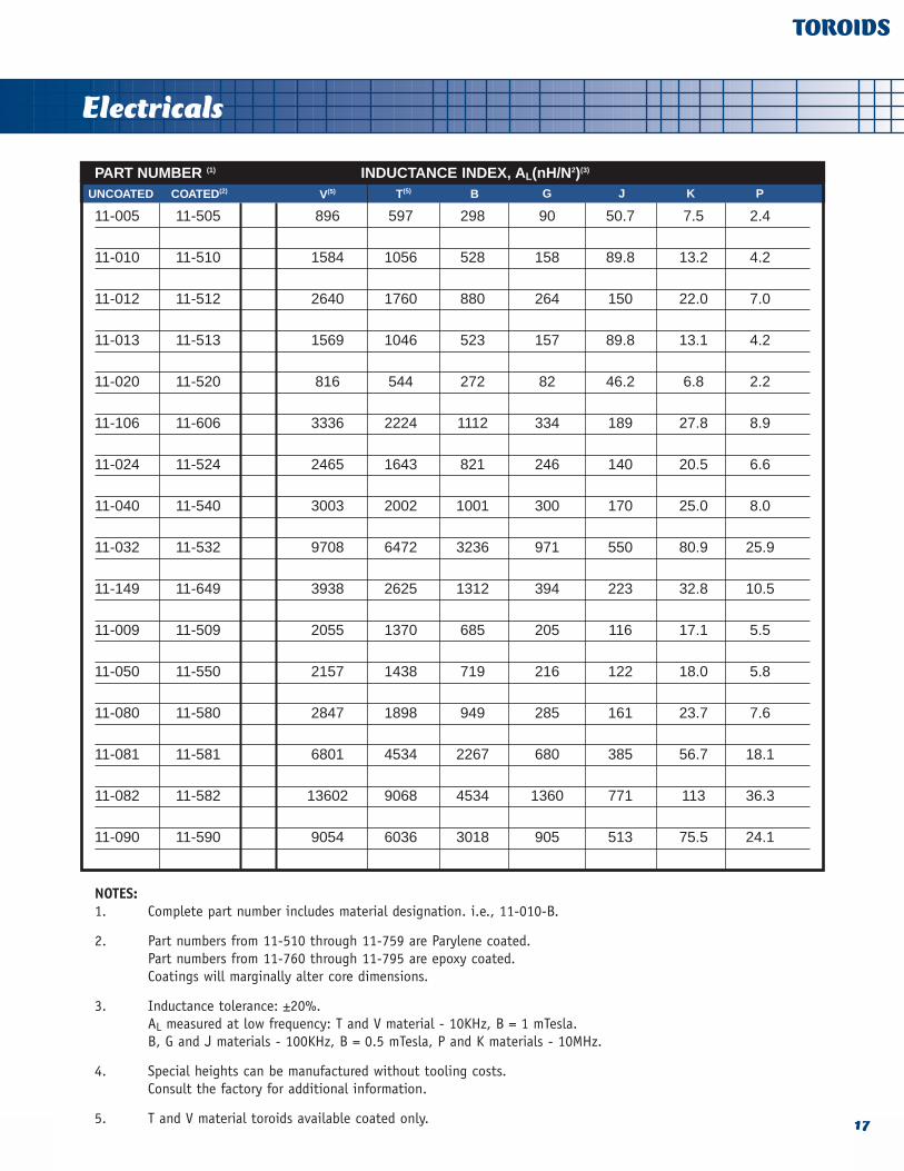
PART NUMBER (1) INDUCTANCE INDEX, AL(nH/N2)(3)
11-005 11-505 896 597 298 90 50.7 7.5 2.4
11-010 11-510 1584 1056 528 158 89.8 13.2 4.2
11-012 11-512 2640 1760 880 264 150 22.0 7.0
11-013 11-513 1569 1046 523 157 89.8 13.1 4.2
11-020 11-520 816 544 272 82 46.2 6.8 2.2
11-106 11-606 3336 2224 1112 334 189 27.8 8.9
11-024 11-524 2465 1643 821 246 140 20.5 6.6
11-040 11-540 3003 2002 1001 300 170 25.0 8.0
11-032 11-532 9708 6472 3236 971 550 80.9 25.9
11-149 11-649 3938 2625 1312 394 223 32.8 10.5
11-009 11-509 2055 1370 685 205 116 17.1 5.5
11-050 11-550 2157 1438 719 216 122 18.0 5.8
11-080 11-580 2847 1898 949 285 161 23.7 7.6
11-081 11-581 6801 4534 2267 680 385 56.7 18.1
11-082 11-582 13602 9068 4534 1360 771 113 36.3
11-090 11-590 9054 6036 3018 905 513 75.5 24.1
NOTES:1. Complete part number includes material designation. i.e., 11-010-B.
2. Part numbers from 11-510 through 11-759 are Parylene coated.Part numbers from 11-760 through 11-795 are epoxy coated. Coatings will marginally alter core dimensions.
3. Inductance tolerance: ±20%.AL measured at low frequency: T and V material - 10KHz, B = 1 mTesla.B, G and J materials - 100KHz, B = 0.5 mTesla, P and K materials - 10MHz.
4. Special heights can be manufactured without tooling costs.Consult the factory for additional information.
5. T and V material toroids available coated only.
UNCOATED COATED(2) V(5) T(5) B G J K P
Dimensions
18
TOROIDS
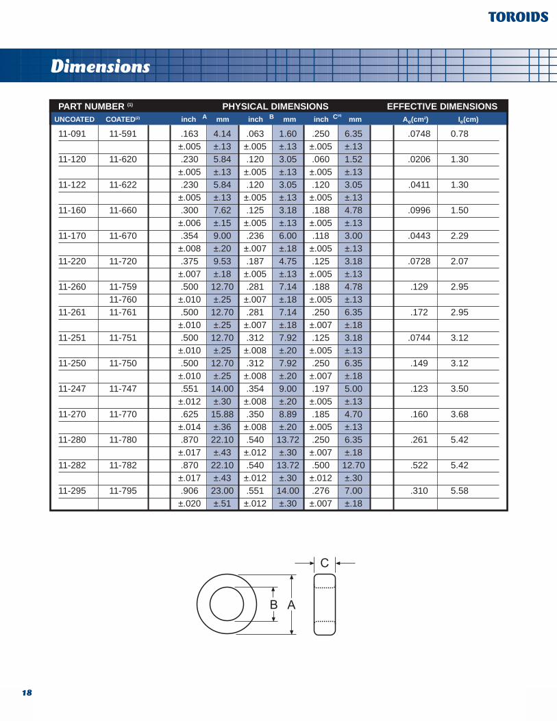
PART NUMBER (1) PHYSICAL DIMENSIONS EFFECTIVE DIMENSIONS
11-091 11-591 .163 4.14 .063 1.60 .250 6.35 .0748 0.78±.005 ±.13 ±.005 ±.13 ±.005 ±.13
11-120 11-620 .230 5.84 .120 3.05 .060 1.52 .0206 1.30±.005 ±.13 ±.005 ±.13 ±.005 ±.13
11-122 11-622 .230 5.84 .120 3.05 .120 3.05 .0411 1.30±.005 ±.13 ±.005 ±.13 ±.005 ±.13
11-160 11-660 .300 7.62 .125 3.18 .188 4.78 .0996 1.50±.006 ±.15 ±.005 ±.13 ±.005 ±.13
11-170 11-670 .354 9.00 .236 6.00 .118 3.00 .0443 2.29±.008 ±.20 ±.007 ±.18 ±.005 ±.13
11-220 11-720 .375 9.53 .187 4.75 .125 3.18 .0728 2.07±.007 ±.18 ±.005 ±.13 ±.005 ±.13
11-260 11-759 .500 12.70 .281 7.14 .188 4.78 .129 2.9511-760 ±.010 ±.25 ±.007 ±.18 ±.005 ±.13
11-261 11-761 .500 12.70 .281 7.14 .250 6.35 .172 2.95±.010 ±.25 ±.007 ±.18 ±.007 ±.18
11-251 11-751 .500 12.70 .312 7.92 .125 3.18 .0744 3.12±.010 ±.25 ±.008 ±.20 ±.005 ±.13
11-250 11-750 .500 12.70 .312 7.92 .250 6.35 .149 3.12±.010 ±.25 ±.008 ±.20 ±.007 ±.18
11-247 11-747 .551 14.00 .354 9.00 .197 5.00 .123 3.50±.012 ±.30 ±.008 ±.20 ±.005 ±.13
11-270 11-770 .625 15.88 .350 8.89 .185 4.70 .160 3.68±.014 ±.36 ±.008 ±.20 ±.005 ±.13
11-280 11-780 .870 22.10 .540 13.72 .250 6.35 .261 5.42±.017 ±.43 ±.012 ±.30 ±.007 ±.18
11-282 11-782 .870 22.10 .540 13.72 .500 12.70 .522 5.42±.017 ±.43 ±.012 ±.30 ±.012 ±.30
11-295 11-795 .906 23.00 .551 14.00 .276 7.00 .310 5.58±.020 ±.51 ±.012 ±.30 ±.007 ±.18
UNCOATED Ae(cm2) Ie(cm)COATED(2) inch mmA inch mmB inch mmC(4)
Electricals
19
TOROIDS
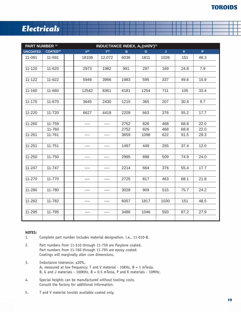
PART NUMBER (1) INDUCTANCE INDEX, AL(nH/N2)(3)
11-091 11-591 18108 12.072 6036 1811 1026 151 48.3
11-120 11-620 2973 1982 991 297 169 24.8 7.9
11-122 11-622 5949 3966 1983 595 337 49.6 15.9
11-160 11-660 12542 8361 4181 1254 711 105 33.4
11-170 11-670 3645 2430 1215 365 207 30.4 9.7
11-220 11-720 6627 4418 2209 663 376 55.2 17.7
11-260 11-759 ---- ---- 2752 826 468 68.8 22.011-760 2752 826 468 68.8 22.0
11-261 11-761 ---- ---- 3659 1098 622 91.5 29.3
11-251 11-751 ---- ---- 1497 449 255 37.4 12.0
11-250 11-750 ---- ---- 2995 898 509 74.9 24.0
11-247 11-747 ---- ---- 2214 664 376 55.4 17.7
11-270 11-770 ---- ---- 2725 817 463 68.1 21.8
11-280 11-780 ---- ---- 3028 909 515 75.7 24.2
11-282 11-782 ---- ---- 6057 1817 1030 151 48.5
11-295 11-795 ---- ---- 3486 1046 593 87.2 27.9
NOTES:1. Complete part number includes material designation. i.e., 11-010-B.
2. Part numbers from 11-510 through 11-759 are Parylene coated.Part numbers from 11-760 through 11-795 are epoxy coated. Coatings will marginally alter core dimensions.
3. Inductance tolerance: ±20%.AL measured at low frequency: T and V material - 10KHz, B = 1 mTesla.B, G and J materials - 100KHz, B = 0.5 mTesla, P and K materials - 10MHz.
4. Special heights can be manufactured without tooling costs.Consult the factory for additional information.
5. T and V material toroids available coated only.
UNCOATED COATED(2) V(5) T(5) B G J K P
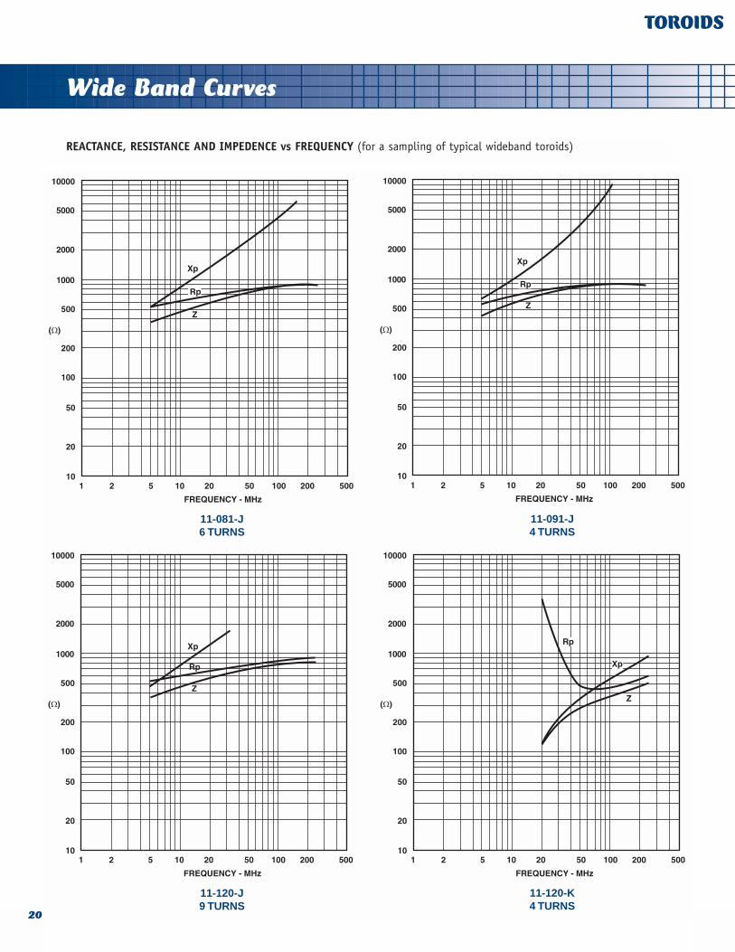
Wide Band Curves
REACTANCE, RESISTANCE AND IMPEDENCE vs FREQUENCY (for a sampling of typical wideband toroids)
20
TOROIDS
11-081-J6 TURNS
11-091-J4 TURNS
11-120-J9 TURNS
11-120-K4 TURNS
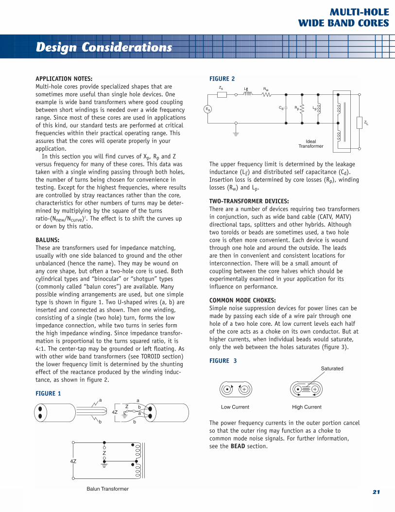
Design Considerations
APPLICATION NOTES:Multi-hole cores provide specialized shapes that aresometimes more useful than single hole devices. Oneexample is wide band transformers where good couplingbetween short windings is needed over a wide frequencyrange. Since most of these cores are used in applicationsof this kind, our standard tests are performed at criticalfrequencies within their practical operating range. Thisassures that the cores will operate properly in yourapplication.
In this section you will find curves of Xp, Rp and Zversus frequency for many of these cores. This data wastaken with a single winding passing through both holes,the number of turns being chosen for convenience intesting. Except for the highest frequencies, where resultsare controlled by stray reactances rather than the core,characteristics for other numbers of turns may be deter-mined by multiplying by the square of the turns ratio-(Nnew/Ncurve)2. The effect is to shift the curves upor down by this ratio.
BALUNS: These are transformers used for impedance matching,usually with one side balanced to ground and the otherunbalanced (hence the name). They may be wound onany core shape, but often a two-hole core is used. Bothcylindrical types and “binocular” or “shotgun” types(commonly called “balun cores”) are available. Manypossible winding arrangements are used, but one simpletype is shown in figure 1. Two U-shaped wires (a, b) areinserted and connected as shown. Then one winding,consisting of a single (two hole) turn, forms the lowimpedance connection, while two turns in series formthe high impedance winding. Since impedance transfor-mation is proportional to the turns squared ratio, it is4:1. The center-tap may be grounded or left floating. Aswith other wide band transformers (see TOROID section)the lower frequency limit is determined by the shuntingeffect of the reactance produced by the winding induc-tance, as shown in figure 2.
FIGURE 1
FIGURE 2
The upper frequency limit is determined by the leakageinductance (Ll) and distributed self capacitance (Cd).Insertion loss is determined by core losses (Rp), windinglosses (Rw) and Lp.
TWO-TRANSFORMER DEVICES:There are a number of devices requiring two transformersin conjunction, such as wide band cable (CATV, MATV)directional taps, splitters and other hybrids. Althoughtwo toroids or beads are sometimes used, a two holecore is often more convenient. Each device is woundthrough one hole and around the outside. The leads are then in convenient and consistent locations for interconnection. There will be a small amount of coupling between the core halves which should beexperimentally examined in your application for itsinfluence on performance.
COMMON MODE CHOKES: Simple noise suppression devices for power lines can bemade by passing each side of a wire pair through onehole of a two hole core. At low current levels each halfof the core acts as a choke on its own conductor. But athigher currents, when individual beads would saturate,only the web between the holes saturates (figure 3).
FIGURE 3
The power frequency currents in the outer portion cancelso that the outer ring may function as a choke to common mode noise signals. For further information, see the BEAD section.
21
MULTI-HOLEWIDE BAND CORES

Dimensions
22
MULTI-HOLEWIDE BAND CORES
PART NUMBER (1) A H B(4) E C
12-315(2) .136 3.45 .034 .86 .093 2.36 .057 1.45 .079 2.01
±.010 ±.25 ±.005 ±.13 ±.010 ±.25 REF REF ±.007 ±.18
12-322 .200 5.08 .047 1.19 .120 3.05 .105 2.67 .120 3.05
±.010 ±.25 ±.005 ±.13 ±.005 ±.13 REF REF ±.007 ±.18
12-328 .248 6.30 .047 1.19 .125 3.18 .115 2.92
±.012 ±.30 ±.006 ±.15 ±.010 ±.25 ±.015 ±.38
12-330 .248 6.30 .047 1.19 .255 6.48 .115 2.92
±.012 ±.30 ±.006 ±.15 ±.016 ±.41 ±.015 ±.38
12-332 .248 6.30 .047 1.19 .472 11.99 .115 2.92
±.012 ±.30 ±.006 ±.15 ±.016 ±.41 ±.015 ±.38
12-340(2) .275 6.99 .073 1.85 .125 3.18 .115 2.92 .160 4.06
±.012 ±.30 ±.006 ±.15 ±.010 ±.25 REF. REF ±.010 ±.25
12-345(2) .275 6.99 .073 1.85 .250 6.35 .115 2.92 .160 4.06
±.012 ±.30 ±.006 ±.15 ±.015 ±.38 REF. REF. ±.010 ±.25
12-350(2) .275 6.99 .073 1.85 .300 7.62 .115 2.92 .160 4.06
±.012 ±.30 ±.006 ±.15 ±.015 ±.38 REF. REF. ±.010 ±.25
12-360(3) .525 13.34 .150 3.81 .260 6.60 .225 5.72 .295 7.49
±.025 ±.64 ±.010 ±.25 ±.010 ±.25 ±.010 ±.25 ±.015 ±.38
12-365(3) .525 13.34 .150 3.81 .565 14.35 .225 5.72 .295 7.49
±.025 ±.64 ±.010 ±.25 ±.020 ±.51 ±.010 ±.25 ±.015 ±.38
12-430 .257 6.53 .052 1.32 .255 6.48 .108 2.74
±.010 ±.25 ±.005 ±.13 ±.016 ±.41 ±.007 ±.18
12-432 .257 6.53 .052 1.32 .472 11.99 .108 2.74
±.010 ±.25 ±.005 ±.13 ±.016 ±.41 ±.007 ±.18
inch mm inch mm inch mm inch mm inch mm
FIGURE 1 FIGURE 2

Electricals
23
MULTI-HOLEWIDE BAND CORES
NOMINAL ELECTRICALS
PART NUMBER(1) B G J K
12-315(2) 3,700 50 1110 42 629 37 92.5 ---- 1
12-322 5,639 ---- 1692 ---- 959 ---- 141 ---- 1
12-328 7,508 88 2252 ---- 1276 ---- 188 94 2
12-330 15,300 ----(7) 4590 --- 2601 ---- 383 ---- 2
12-332 28,350 ---- 8505 ---- 4820 308 709 ---- 2
12-340(2) 4,576 ---- 1373 52 961 ---- 114 64 1
12-345(2) 9,152 ---- 2746 103 1922 91 229 ---- 1
12-350(2) 10,983 136 3295 124 2306 ---- 275 156 1
12-360(3) 8,312 ---- 2491 94 1745 ---- 208 127 1
12-365(3) 18,062 139 5419 204 3793 175 452 262 1
12-430 13,433 ---- 4030 ---- 2821 ---- 336 ---- 2
12-432 24,864 ---- 7459 ---- 5222 260 622 ---- 2
NOTES:1. Complete part number includes material designation. i.e., 12-345-G.
2. Part is tumbled to remove sharp edges.
3. Part has chamfered edges.
4. Special heights can be manufactured without tooling costs.
5. Inductance tolerance varies with part number. Consult the factory for further information.
6. Impedance data shown is nominal, measured on a short length of 20AWG wire wound hole-to-hole at frequency shown. Normal tolerance is ±25%.
7. Impedance data not available at time of printing. Consult the factory for further information.
FIG.AL
(nH/N2) Z@10 MHzAL
(nH/N2) Z@100 MHzAL
(nH/N2) Z@100 MHzAL
(nH/N2) Z@250 MHz(5) (5)(6) (6) (6) (6)(5) (5)

Material Curves
24
MULTI-HOLEWIDE BAND CORES
REACTANCE, RESISTANCE AND IMPEDANCE vs FREQUENCY
J MATERIAL
12-328-J4 TURNS
12-330-J3 TURNS
12-345-J3 TURNS
12-340-J4 TURNS
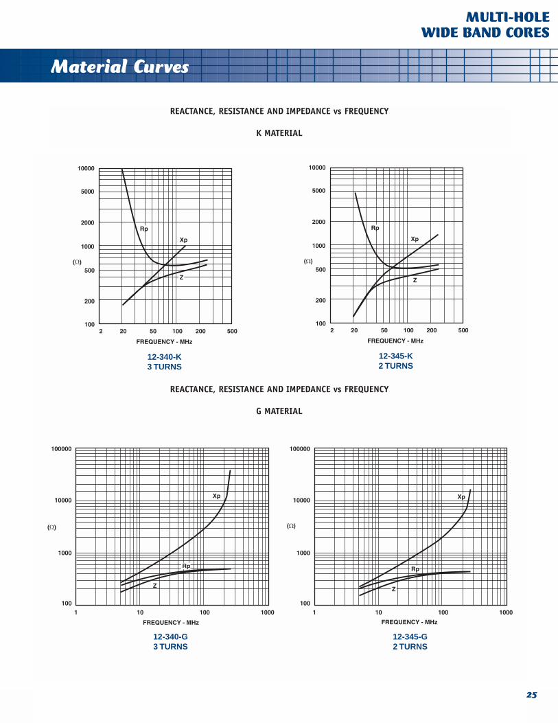
Material Curves
25
MULTI-HOLEWIDE BAND CORES
REACTANCE, RESISTANCE AND IMPEDANCE vs FREQUENCY
K MATERIAL
12-340-K3 TURNS
12-345-K2 TURNS
12-345-G2 TURNS
12-340-G3 TURNS
REACTANCE, RESISTANCE AND IMPEDANCE vs FREQUENCY
G MATERIAL

Design Considerations
Ferrite beads provide a simple, economical method forattenuating high frequency noise or oscillations. By slipping a bead over a wire, a RF choke or suppressor is produced which possesses low impedance at low fre-quencies and relatively high impedance over a wide highfrequency band. The effectiveness of this impedance inreducing EMI or RFI depends on the relative magnitudesof the source, suppressor and load impedances. Beadsare also available fixed on a wire, taped and reeled forautomatic insertion.
HOW THEY WORK:At high frequencies the permeability and losses of fer-rite vary with frequency. The permeability declines whilethe losses rise to a broad peak. The equivalent circuitand curves in figures 1 and 2 show how this propertycan be used as a broad band filter.
FIGURE 1
FIGURE 2
Ordinarily, beads of ferrite are slipped over a wire producing a one-turn device. To low frequencies the component presents a small inductance whose reactancecan often be neglected, while to high frequencies thedevice presents a higher series resistance with near zeroreactance. Since this resistance is a result of materiallosses, it is a true dissipative element. Furthermore, sincethe reactance is low, there is little chance for resonancewith stray capacitance which would spoil the suppression.
DETERMINING IMPEDANCE:In this catalog curves are presented for some standardparts. They show inductance, resistance and impedanceversus frequency for a single straight-through conductor(1 turn). Similar values for other sizes in the samematerials can be calculated by the ratio of Ae/le(equation 1) for the two cores.
Here OD, ID and H are the dimensions in inches of acylindrical bead. Also, le and Ae (in cm and cm2) arelisted in this catalog for all standard parts. As an example, suppose you want to know L and R for a 21-110-J at 20 MHz. Curves for a similar core, 21-030-J,are given and its Ae/le is .033/.64 = .0516. Also fromthe table , for 21-110-J, Ae/le is .029/.73 = .0397.Therefore, the L and R on the curves should be multi-plied by .0397/.0516 = .770, giving .06m H inductanceand 13.1 ohms resistance. For standard beads we alsolist an impedance for each core. This consists of a measurement near the peak impedance frequency usinga single turn of short #20 AWG wire. This makes anexcellent incoming QC test, as well as a means for comparing the effectiveness of various core choices.
CHOOSING A BEAD:The best material is one that gives high impedance orresistance at the noise frequencies and low at thedesired signal frequencies. Since the frequency range for high resistance is quite wide - about two decades -this choice is simple and non-critical. It also is necessary that the impedance presented by the bead at noise frequencies be large enough compared to othercircuit impedances to provide the desired attenuation.Frequently the source and load impedance are unknown,but if they are known, insertion loss may be calculatedfrom:
INCREASING SUPPRESSION:Bead impedance is directly proportional to the totalheight dimension and may be increased either by usinglonger beads or by stringing more than one. The effectof height on J material beads is shown in the BeadElectrical Performance pages. Either method giving thesame total height is equivalent. Since the magnetic fieldis totally contained, it does not matter whether thebeads are touching or separated. This approach is valid
26
BEADSEMI/RFI
1
2

Design Considerations
at all frequencies through VHF, but reliable measure-ments are difficult at higher frequencies. Impedance isalso proportional to Ae/le (equation 1) and this may beused to estimate the parameters for various cores.
Higher impedances can also be obtained by windingthe wire through the core more than once. Resistanceand inductance are proportional to the number of turnssquared. Because of capacitance between turns thistechnique is most effective at lower frequencies. Also,since a greater length of smaller cross section wire isused, dc resistance will increase.
A different approach can be taken at low frequencieswhere there is significant inductance. The filter can betuned for maximum attenuation at a specific frequencyby simply connecting a resonating capacitor from theoutput side to ground. Because of the high ac resist-ance, oscillation is rarely a problem and attenuation isalso present at other frequencies.
EXCITATION LEVEL:High currents,which are most likely to occur at dc or lowfrequencies because of the low impedance, can causesignificant magnetizing force.
This can reduce the impedance and suppression. Sincebeads are often used with only one turn, fairly high currents can be tolerated before saturation isapproached. At saturation, inductance and resistancewill be low, but will recover upon removal of the highfield. Curves in the Bead Electrical Performance pagesshow the effect of dc current on impedance for certainbeads. If the magnetizing force (H) of low frequencies istoo great, it will be necessary to increase the effective magnetic path length (le). Parts listed in theTOROID section generally have larger le for similar Ae/leratios. For further increases in le see the discussion onSlotted Toroids in the Toroid section.
Another solution to problems concerning low frequen-cy current takes advantage of the fact that much conducted RFI is common-mode. Then it is practical towind the core as a common-mode choke. The dots in figure 3 indicate the winding sequence, that is, bothwindings are put on the same way (bifilar). Then themagnetic fields of the two windings cancel for normalpower currents but aid for common-mode noise currents.
High RF levels can cause excitation greater than thatused for data in this catalog. Often these will increasethe effective resistance because of the contribution ofhysteresis losses.
FIGURE 3
ENVIRONMENT:Ferrites are inert ceramics free of any organic substances. They will not be degraded by most environ-ments, including temperatures up to a few hundreddegrees centigrade. Magnetic properties vary somewhatwith temperature. Generally, inductance increases withincreasing temperature while the effect on resistance is small. Above the Curie temperature the bead is non-magnetic and no suppression can be expected. Thiseffect is completely reversible and once the temperatureis reduced below that point, normal performance isregained.
COATING:Because of the high volume resistivity of nickel-zinc ferrites (G,J,K and P materials), these beads may beconsidered insulators in most applications. Manganese-zinc ferrites (B,material, for example) are semiconduc-tors and may need to be insulated if they are free toshort circuit two or more conductors. Insulating coatings may be applied. This coating should be softenough to not stress the core upon curing or duringtemperature cycling, withstand normal environments(including cleaning solvents) and provide insulation.
We offer Parylene® C, a vapor deposited conformalcoating. Parylene produces an exceptionally uniformcoating, normally about .0007" thick.
Standard minimum voltage breakdown is 500VAC. If ahigher level of protection is required, please consultwith our engineering department.
27
BEADSEMI/RFI
3 x 79.55 A/m

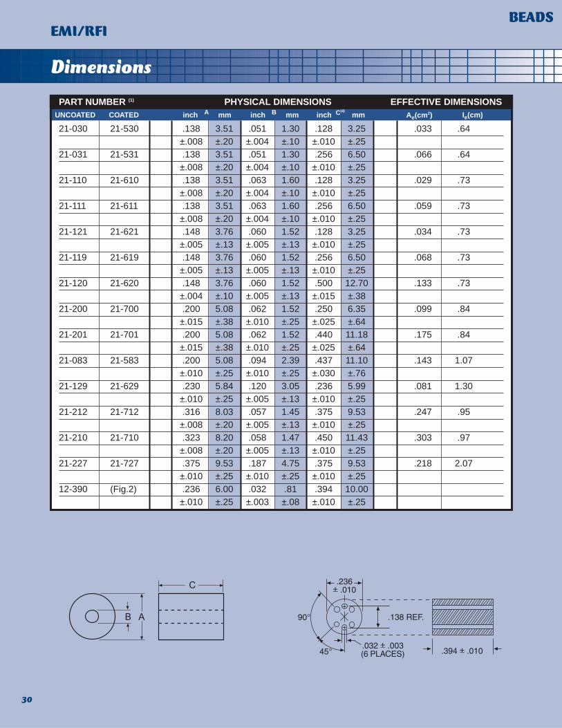
Dimensions
28
BEADSEMI/RFI
PART NUMBER (1) PHYSICAL DIMENSIONS EFFECTIVE DIMENSIONS
21-095 21-595 .075 1.91 .030 76 .150 3.81 .020 .37
±.005 ±.13 ±.002 ±.05 ±.010 ±.25
21-172 21-672 .095 2.41 .053 1.35 .060 1.52 .008 .56
±.005 ±.13 ±.005 ±.13 ±.005 ±.13
21-170 21-670 .095 2.41 .053 1.35 .150 3.81 .020 .56
±.003 ±.08 ±.003 ±.08 ±.005 ±.13
21-185 21-685 .098 2.49 .047 1.19 .120 3.05 .019 .53
±.004 ±.10 ±.004 ±.10 ±.005 ±.13
21-060 21-560 .110 2.79 .067 1.70 .150 3.81 .020 .68
±.005 ±.13 ±.004 ±.10 ±.010 ±.25
21-020 21-520 .120 3.05 .047 1.19 .125 3.18 .027 .58
±.005 ±.13 ±.003 ±.08 ±.008 ±.20
21-130 21-630 .138 3.51 .031 .79 .128 3.25 .037 .48
±.008 ±.20 ±.003 ±.08 ±.010 ±.25
21-134 21-634 .138 3.51 .031 .79 .175 4.45 .050 .48
±.008 ±.20 ±.003 ±.08 ±.010 ±.25
21-132 21-632 .138 3.51 .031 .79 .256 6.50 .074 .48
±.008 ±.20 ±.003 ±.08 ±.010 ±.25
21-133 21-633 .138 3.51 .031 .79 .350 8.89 .101 .48
±.008 ±.20 ±.003 ±.08 ±.015 ±.38
21-142 21-642 .138 3.51 .037 .94 .150 3.81 .042 .53
±.008 ±.20 ±.002 ±.05 ±.010 ±.25
21-140 21-640 .138 3.51 .037 .94 .175 4.45 .049 .53
±.008 ±.20 ±.002 ±.05 ±.010 ±.25
21-042 21-542 .138 3.51 .049 1.24 .236 5.99 .062 .63
±.008 ±.20 ±.004 ±.10 ±.010 ±.25
21-049 21-549 .138 3.51 .051 1.30 .118 3.00 .031 .64
±.008 ±.20 ±.004 ±.10 ±.010 ±.25
UNCOATED Ae(cm2) Ie(cm)COATED inch mmA inch mmB inch mmC(4)

Electricals
29
BEADSEMI/RFI
PART NUMBER(1) B J K
21-095 21-595 3491 43 594 39 87.3 50
21-172 21-672 889 11 151 10 22.2 13
21-170 21-670 2223 27 378 25 55.6 32
21-185 21-685 2240 28 381 25 56.0 32
21-060 21-560 1889 23 321 21 47.2 27
21-020 21-520 2976 37 506 33 74.4 42
21-130 21-630 4855 60 825 54 121 69
21-134 21-634 6638 82 1128 74 166 94
21-132 21-632 9710 120 1651 108 243 138
21-133 21-633 13275 164 2257 147 332 189
21-142 21-642 5015 62 853 56 125 71
21-140 21-640 5851 72 995 65 146 83
21-042 21-542 6207 77 1055 69 155 88
21-049 21-549 2983 37 507 33 74.6 42
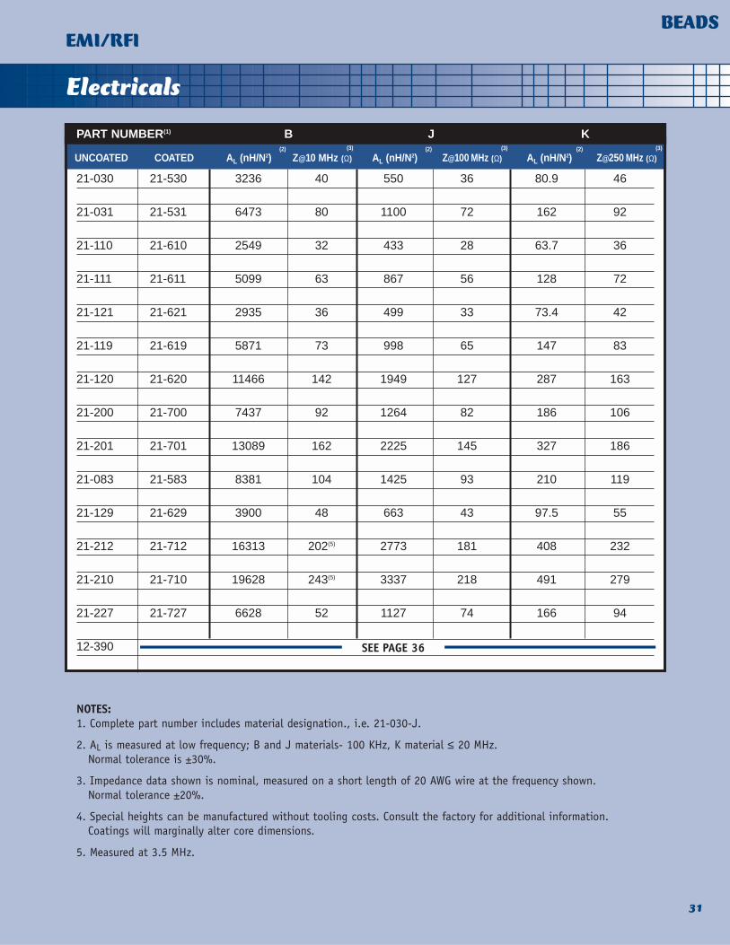
NOTES:1. Complete part number includes material designation., i.e. 21-030-J.
2. AL is measured at low frequency; B and J materials - 100 KHz, K material ≤ 20 MHz.Normal tolerance is ±30%.
3. Impedance data shown is nominal, measured on a short length of 20 AWG wire at the frequency shown. Normal tolerance ±20%.
4. Special heights can be manufactured without tooling costs. Consult the factory for additional information.Coatings will marginally alter core dimensions.
AL (nH/N2)UNCOATED COATED Z@10 MHz (Ω) Z@100 MHz (Ω)(2)
AL (nH/N2)(2)(3) (3)
Z@250 MHz (Ω)AL (nH/N2)(2) (3)
Dimensions
30
BEADSEMI/RFI
PART NUMBER (1) PHYSICAL DIMENSIONS EFFECTIVE DIMENSIONS
21-030 21-530 .138 3.51 .051 1.30 .128 3.25 .033 .64±.008 ±.20 ±.004 ±.10 ±.010 ±.25
21-031 21-531 .138 3.51 .051 1.30 .256 6.50 .066 .64±.008 ±.20 ±.004 ±.10 ±.010 ±.25
21-110 21-610 .138 3.51 .063 1.60 .128 3.25 .029 .73±.008 ±.20 ±.004 ±.10 ±.010 ±.25
21-111 21-611 .138 3.51 .063 1.60 .256 6.50 .059 .73±.008 ±.20 ±.004 ±.10 ±.010 ±.25
21-121 21-621 .148 3.76 .060 1.52 .128 3.25 .034 .73±.005 ±.13 ±.005 ±.13 ±.010 ±.25
21-119 21-619 .148 3.76 .060 1.52 .256 6.50 .068 .73±.005 ±.13 ±.005 ±.13 ±.010 ±.25
21-120 21-620 .148 3.76 .060 1.52 .500 12.70 .133 .73±.004 ±.10 ±.005 ±.13 ±.015 ±.38
21-200 21-700 .200 5.08 .062 1.52 .250 6.35 .099 .84±.015 ±.38 ±.010 ±.25 ±.025 ±.64
21-201 21-701 .200 5.08 .062 1.52 .440 11.18 .175 .84±.015 ±.38 ±.010 ±.25 ±.025 ±.64
21-083 21-583 .200 5.08 .094 2.39 .437 11.10 .143 1.07±.010 ±.25 ±.010 ±.25 ±.030 ±.76
21-129 21-629 .230 5.84 .120 3.05 .236 5.99 .081 1.30±.010 ±.25 ±.005 ±.13 ±.010 ±.25
21-212 21-712 .316 8.03 .057 1.45 .375 9.53 .247 .95±.008 ±.20 ±.005 ±.13 ±.010 ±.25
21-210 21-710 .323 8.20 .058 1.47 .450 11.43 .303 .97±.008 ±.20 ±.005 ±.13 ±.010 ±.25
21-227 21-727 .375 9.53 .187 4.75 .375 9.53 .218 2.07±.010 ±.25 ±.010 ±.25 ±.010 ±.25
12-390 (Fig.2) .236 6.00 .032 .81 .394 10.00±.010 ±.25 ±.003 ±.08 ±.010 ±.25
UNCOATED Ae(cm2) Ie(cm)COATED inch mmA inch mmB inch mmC(4)
Electricals
31
BEADSEMI/RFI
PART NUMBER(1) B J K
21-030 21-530 3236 40 550 36 80.9 46
21-031 21-531 6473 80 1100 72 162 92
21-110 21-610 2549 32 433 28 63.7 36
21-111 21-611 5099 63 867 56 128 72
21-121 21-621 2935 36 499 33 73.4 42
21-119 21-619 5871 73 998 65 147 83
21-120 21-620 11466 142 1949 127 287 163
21-200 21-700 7437 92 1264 82 186 106
21-201 21-701 13089 162 2225 145 327 186
21-083 21-583 8381 104 1425 93 210 119
21-129 21-629 3900 48 663 43 97.5 55
21-212 21-712 16313 202(5) 2773 181 408 232
21-210 21-710 19628 243(5) 3337 218 491 279
21-227 21-727 6628 52 1127 74 166 94
12-390
NOTES:1. Complete part number includes material designation., i.e. 21-030-J.
2. AL is measured at low frequency; B and J materials- 100 KHz, K material ≤ 20 MHz.Normal tolerance is ±30%.
3. Impedance data shown is nominal, measured on a short length of 20 AWG wire at the frequency shown. Normal tolerance ±20%.
4. Special heights can be manufactured without tooling costs. Consult the factory for additional information.Coatings will marginally alter core dimensions.
5. Measured at 3.5 MHz.
AL (nH/N2)UNCOATED COATED Z@10 MHz (Ω) Z@100 MHz (Ω)(2)
AL (nH/N2)(2)(3) (3)
Z@250 MHz (Ω)AL (nH/N2)(2) (3)
SEE PAGE 36

Material Curves
32
BEADSEMI/RFI
SERIES INDUCTANCE, RESISTANCE AND IMPEDANCE vs FREQUENCY
B MATERIAL
J MATERIAL

Material Curves
33
BEADSEMI/RFI
SERIES INDUCTANCE, RESISTANCE AND IMPEDANCE vs FREQUENCY
THE EFFECT OF HEIGHT ON INDUCTANCE AND RESISTANCE
K MATERIAL
J MATERIAL

Material Curves
34
BEADSEMI/RFI
IMPEDANCE vs FREQUENCY WITH DC CURRENT
IMPEDANCE vs FREQUENCY FOR VARIOUS SIZES
B MATERIAL
B MATERIAL
J MATERIAL

Ferronics offers beads on leads in two materials and six different bead lengths. The 82 Series bulk packaged axial wirebeads facilitate manual operations while the 92 Series, taped and reeled per RS-296-(Latest Revision), is intended forautomatic component insertion applications.
35
TAPED & REELEDBEADS ON LEADSEMI/RFI
PART NUMBER (2) (4) LENGTH(3)
92-130-B 82-130-B .128 3.25 60 –
92-130-J 82-130-J ±.010 ±.25 – 48
92-132-B 82-132-B .256 6.50 120 –
92-132-J 82-132-J ±.010 ±.25 – 96
92-133-B 82-133-B .350 8.89 164 –
92-133-J 82-133-J ±.015 ±.38 – 131
92-134-B 82-134-B .175 4.45 82 –
92-134-J 82-134-J ±.010 ±.25 – 66
92-135-B 82-135-B .450 11.43 210 –
92-135-J 82-135-J ±.015 ±.38 – 169
92-136-B 82-136-B .550 13.97 257 –
92-136-J 82-136-J ±.015 ±.38 – 206
NOTES:
1. Impedance tolerance ±20%.
2. Parylene® coated cores - change 1 to a 6, i.e., 92-132-B to 92-632-B. For additional information on Parylenecoating,refer to the BEADS section.
3. Bead length can be varied without tooling costs. Consult the factory for additional information.
4. Available in other materials. Consult the factory.
TAPED AND REELED BULK PACKAGED inch Z Ω @10 MHz Z Ω @100 MHzmm (1) (1)

Ferronics offers a line of 6 hole beads and chokes forapplications where a single hole bead does not providethe impedence level desired. Ferronics provides six-holebeads in the following materials:
J Material - The best choice in 20-300MHz noise suppression applications.
K Material - Suited for 50-500MHz applications.
The standard chokes are offered in 1.5, 2.5 and 3 turnversions. Ferronics also offers a common mode choke version with 2 x 1.5 turns. (See Table 1 and accompany-ing figures.) An industry standard, the six-hole bead canbe custom wound to meet your particular requirements.
36
SIX HOLE CHOKESEMI/RFI
PART NUMBER DESCRIPTION MIN Z (Ω) FREQ (MHz) FIG.
82-151-J 12-390-J WITH 11⁄2 TURNS* 400 100 1
82-151-K 12-390-K WITH 11⁄2 TURNS* 450 100 1
82-152-J 12-390-J WITH 21⁄2 TURNS* 600 100 2
82-152-K 12-390-K WITH 21⁄2 TURNS* 675 100 2
82-153-J 12-390-J WITH 2 x 11⁄2 TURNS* 400 100 3
82-153-K 12-390-K WITH 2 x 11⁄2 TURNS* 450 100 3
82-154-J 12-390-J WITH 3 TURNS* 800 50 4
82-154-K 12-390-K WITH 3 TURNS* 1000 70 4
*#24AWG tinned copper wire is standard.Refer to Part Number 12-390 in BEADS section for dimensional data.
TABLE 1

Ferronics has developed a line of ferrite chokes called Z-MAX that are specifically engineered for maximumimpedance to more effectively suppress high frequencynoise or oscillations. Z-MAX begin where simple beadsleave off. They have two to three times the impedanceof a standard bead occupying the same space. This is amajor benefit when you consider the value of space on acircuit board.
Z-MAX chokes are both color coded and marked tofacilitate inventory control and production. This featurealone translates into substantial savings . At the top ofthe Z-MAX line is the “Gold series...so effective over awide range of frequencies it’s patented. Z-MAX “Gold”
has the unique capability of providing a very flat impedance profile across a broad range of frequencies,from 5 to 500 MHz.
The “Gold” series Z-MAX chokes take the guessworkout of noise suppression. You no longer need to knowthe precise frequencies of the noise causing EMI/RFIproblems. By using a “Gold” series Z-MAX choke right offthe shelf, you can dampen a full range of frequenciesnecessary to eliminate most noise.
To suit your needs even further, Ferronics can adjustthe amplitude of impedance to accommodate most practical requirements. Z-MAX chokes are available bulkpackaged or radially taped on reels.
37
Z-MAX CHOKESEMI/RFI
Note: Impedance measured with leads trimmed to simulate typical application.
SPECIFICATIONS
MINIMUM IMPEDANCE 140 145 105 Ω@ 10 100 10 & 100 MHz
MINIMUM IMPEDANCE 100 100 100 ΩOVER RANGE 2-40 25-500 5-500 MHz
RATED CURRENT 3 3 3 A
MAXIMUM STORAGE/OPERATING TEMPERATURE 105 105 105 °C
54-100“BLUE”
54-120“RED”
54-140“GOLD” UNITS

Ferronikits
FERRONIKITS Provide a handy selection of ferrite cores for prototypedesigning and emergency “debugging”. Each kit containsa variety of standard cores useful in particular groups ofapplications.
11-V (V TOROIDS) This kit contains toroids manufactured from 15,000µi material and is suited for applications requiring highpermeability with temperature stability. Pulse transformers and filters are typical applications.
11-T (T TOROIDS) This kit contains toroids manufactured from 10,000µimaterial and is suited for applications requiring highpermeability. Pulse transformers and filters are typicalapplications.
11-B (B TOROIDS) This kit contains toroids manufactured from 5000µimaterial and is suited for applications where high permeability and low power losses are required. Typicalapplications are pulse transformers, converters, powertransformers, inductors, and wide band transformersoperating at low frequencies.
11-G (G TOROIDS) This kit contains toroids manufactured from 1500µimaterial and is suited for applications where high levelsof broadband impedance is desired. Filters and RF transformers are typical applications.
11-J (J TOROIDS) This kit contains toroids manufactured from 850µi material. Typical applications include wide band transformers and RF chokes operating above 5 MHz.
11-K (K TOROIDS) This kit contains toroids manufactured from 125µi material and is suited for high frequency applicationswhere high Q above 1 MHz is required. Typical applications are RF inductors, RF power transformers,tuned inductors and transformers, impedance matchingtransformers, and wide band transformers operatingabove 20 MHz.
11-P (P TOROIDS) This kit contains toroids manufactured from 40µi material. It is suited for very high frequency applications, such as transformers or inductors, where high Q above 10 MHz is required.
12-J (J TWIN HOLE CORES) This kit contains twin hole beads and baluns manufac-tured from 850µi material. These parts are particularlysuited for wide band transformers, baluns splitters andtaps operating in the 5 MHz to 1,000 MHz range.
12-K (K TWIN HOLE CORES) This kit contains twin hole beads and baluns manufactured from 125µi material. These parts are best suited as wide band transformers, baluns, splittersand taps operating above 20 MHz.
21-0 BEADS This kit contains ferrite beads manufactured fromFerronics B and J materials and is suitable for noise suppression applications. Ferronics B is best for attenuating unwanted signals in the 1 to 100 MHzrange. Ferronics J is useful from 10 MHz up.
EMI/RFI This kit contains a variety of products commonly utilizedto solve EMI/RFI problems at the board level. Partsinclude single and multi-hole beads, beads on leads, sixhole chokes and Z-MAX chokes. Materials covered are B,J, and K.
38

Ferronikits
39
24-0 EMI/RFIKits Contain:
21-0 BEAD Kits Contain:
12-K BALUNKits Contain:
12-J BALUN Kits Contain:
11-V(1,2)TOROID Kits Contain:
11-G AND 11-T(1,2)
TOROID Kits Contain:
11-B,11-K,11-JAND 11-P(1) TOROID Kits Contain:
NOTES:1. Complete P/N includes material designation, i.e. 11-220-B. Each toroid kit contains one material type.
Properties, effective dimensions and AL values for each size are included.
2. All kit parts are Parylene C coated. G toroids are available uncoated. T and V toroids are available coated only.
24 Each 12-340-J
24 Each 12-345-B
24 Each 12-345-J
24 Each 12-345-K
12 Each 12-390-J
12 Each 12-390-K
24 Each 21-031-B
24 Each 21-031-J
12 Each 21-201-B
12 Each 21-201-J
4 Each 21-227-B
4 Each 21-227-J
12 Each 54-100-1
12 Each 54-120-1
12 Each 54-140-1
12 Each 82-151-J
12 Each 82-151-K
12 Each 82-152-J
12 Each 92-130-J
12 Each 92-132-J
24 Each P/N 21-030-B
24 Each P/N 21-031-B
24 Each P/N 21-030-J
24 Each P/N 21-031-J
24 Each P/N 21-110-J
12 Each P/N 21-201-J
12 Each P/N 21-210-B
24 Each P/N 12-328-K
12 Each P/N 12-330-K
24 Each P/N 12-315-K
24 Each P/N 12-340-K
12 Each P/N 12-345-K
12 Each P/N 12-360-K
6 Each P/N 12-365-K
24 Each P/N 12-328-J
12 Each P/N 12-330-J
24 Each P/N 12-340-J
12 Each P/N 12-345-J
12 Each P/N 12-350-J
12 Each P/N 12-360-J
6 Each P/N 12-365-J
24 Each P/N 11-510-
24 Each P/N 11-543-
24 Each P/N 11-550-
24 Each P/N 11-562-
24 Each P/N 11-620-
24 Each P/N 11-622-
12 Each P/N 11-660-
24 Each P/N 11-510-
24 Each P/N 11-512-
24 Each P/N 11-540-
24 Each P/N 11-550-
24 Each P/N 11-580-
24 Each P/N 11-620-
24 Each P/N 11-622-
24 Each P/N 11-040-
24 Each P/N 11-050-
24 Each P/N 11-080-
24 Each P/N 11-120-
12 Each P/N 11-220-
6 Each P/N 11-250-
6 Each P/N 11-260-

Winding Service
A MONEY SAVING ALTERNATIVEFerronics offers you a money-saving alternative to theway you have traditionally been procuring your woundmagnetic components. Forget about separate purchaseorders for ferrite cores,wire, solder, etc. as well asinspecting and stocking all these items. And forgetabout the uncertainty and high cost of having to findsomeone reliable to do hand winding.
With Ferronics you can satisfy your ferrite needs from a single, dependable source. In addition to ourextensive line of ferrite products, we offer an economical way to hand wind ferrite cores to your exactspecifications. This eliminates the “middleman” andmakes it very cost effective for you to purchase yourcompleted TRANSFORMER, INDUCTOR, CHOKE, or anyconfiguration you require directly from us. You not onlysave time, but overhead, inspection, and inventory costsas well.
HIGH QUALITY AT LOW COST What makes Ferronics the value leader in the industry isa unique blend of high quality products combined withcustomized service... available at low cost.
All ferrites manufactured by Ferronics are producedunder strict quality control supervision and tested inaccordance with the most demanding standards. Thecore winding service we offer is the result of many yearsof careful planning and development on everything fromsite location to inventory and quality control methods.
Each winding job is fully analyzed and customized toyour requirements. For each job, winding models, wind-ing sequence procedures, workmanship specifications,lot identification methods, in-process inspection pointsand final inspection requirements are developed anddocumented.
Everything we do is specifically designed to meet yourindividual ferrite component requirements in a timelyand cost-effective fashion.
Ferronics is also a firm believer in passing savingsalong to its customers. For our customized hand windingservice, we established an offshore facility with lowlabor rates and competitive deliveries.
40