fecstandard · 2020-02-16 · 10 festo fec fc660 0207b deutsch hinweis die verbindungen zwischen...
TRANSCRIPT

Kurz-beschreibung
Brief description
IPCTyp FEC FC660
IPCType FEC FC660
- Deutsch
- English
6553050207b
FEC Standard
Festo FEC FC660 0207b2
Deutsch 3. . . . . . . . . . . . . . . . . . . . . . . . . . . . . . . . . . . . . . . . . . .
English 29. . . . . . . . . . . . . . . . . . . . . . . . . . . . . . . . . . . . . . . . . . . .
Edition: 0207bOriginal: de
© (Festo AG & Co., D-73726 Esslingen, Germany, 2002)Internet: http://www.festo.comE-Mail: [email protected]

Festo FEC FC660 0207b Deutsch 3
1 BenutzerhinweiseDeutsch
Die in diesem Handbuch dokumentierte Kleinsteuerung istfür die Weiterverarbeitung digitaler und analoger Datenkonzipiert.
Weiterführende Informationen zur Kleinsteuerung findenSie im Handbuch zum IPC FEC Standard (Teilenr.: 525368).
VorsichtBeachten Sie unbedingt die im Handbuch IPC FEC Stan-dard aufgeführten– sicherheitstechnischen Hinweise– und den bestimmungsgemäßen Gebrauch der jewei-
ligen Baugruppen und Module.
WarnungAktoren können ungewollt aktiviert und der IPC FECStandard kann beschädigt werden, wenn Baugruppenbei eingeschalteter Spannungsversorgung hinzugefügtoder entfernt werden. Trennen Sie vor Installations- undWartungsarbeiten den IPC FEC Standard von der Span-nungsversorgung.
HinweisEinige in diesem Handbuch beschriebenen Eigenschaf-ten sind mit diesem Gerät technisch möglich, werdenjedoch softwaremäßig nicht unterstützt. Ebenso kön-nen zwischen FST und MWT Funktionsmerkmale vonein-ander abweichen. Näheres ist dem jeweiligen Software-handbuch zu entnehmen.

Festo FEC FC660 0207b Deutsch4
2 Modulübersicht FEC FC660
2
3
4
5
6
1
aJ
aA
aB
87
aC
aD
aE
9
1 Eingang E0.0 bis E0.7
2 Eingang E1.0 bis E1.7
3 Eingang E2.0 bis E2.7
4 Eingang E3.0 bis E3.7
5 Analoge Ein- und Ausgänge
6 Ausgang A0.0 bis A0.7
7 Ausgang A1.0 bis A1.7
8 Spannungsversorgung
9 Status LED (Run/Stop/Error)
aJ Power LED (Spannungsversor-gung)
aA Link/Traffic LED für Netzwerk-aktivität
aB Funktionswahlschalter
aC Netzwerkanschluss 10Base T
aD Kommunikationsschnittstelle(Com)
aE Erweiterungsschnittstelle(Ext)
2
3
4 5 6
1
9 aJ
aA

Festo FEC FC660 0207b Deutsch 5
3 Die Pinbelegung der Anschlussstecker
3.1 Die Pinbelegung der digitalen Ein- und Ausgänge:
PS1 SAC31 als Beispiel
Verteilerleiste 24 V DC 1)
Versorgungsspannung E/A 24 V DC 2)
Eing. E0.0 bis E3.0; Ausg. A0.0 und A1.0
Eing. E0.1 bis E3.1; Ausg. A0.1 und A1.1
Eing. E0.2 bis E3.2; Ausg. A0.2 und A1.2
Eing. E0.3 bis E3.3; Ausg. A0.3 und A1.3
Eing. E0.4 bis E3.4; Ausg. A0.4 und A1.4
Eing. E0.5 bis E3.5; Ausg. A0.5 und A1.5
Eing. E0.6 bis E3.6; Ausg. A0.6 und A1.6
Eing. E0.7 bis E3.7; Ausg. A0.7 und A1.7
Versorgungsspannung E/A 0 V DC 3)
Verteilerleiste 0 V DC 4)
1. ist im SAC 30/31 intern verbunden2. ist ein Einzelkontakt und muss mit ‘24‘ V DC verbunden werden3. ist ein Einzelkontakt und muss mit ‘0‘ V DC verbunden werden4. ist im SAC 30/31 intern verbunden

Festo FEC FC660 0207b Deutsch6
VorsichtEine Verpolung der Versorgung der digitalen Ausgangs-baugruppe ist unter allen Umständen zu vermeiden.Der Einsatz einer externen Absicherung (4 AF) der Aus-gangsbaugruppe wird empfohlen.

Festo FEC FC660 0207b Deutsch 7
3.2 Die Pinbelegung der analogen Ein-/Ausgänge
VorsichtVerwenden Sie zum Anschluss analoger Ein-/ Ausgängeausschließlich den Stecker SAC10 oder SAC30.
Pin Nr. Bezeichnung PS1 SAC10 als Beispiel
1 +24 V
2 OUT0
3 GND OUT0
4 GND IN0
5 IN0
6 GND IN1
7 IN1
8 GND IN2
9 IN2
10 0 V

Festo FEC FC660 0207b Deutsch8
VorsichtEine Verpolung der Versorgung der analogen Ausgangs-baugruppe ist unter allen Umständen zu vermeiden.Der Einsatz einer externen Absicherung (125 mAF) derAusgangsbaugruppe wird empfohlen.
HinweisDie Eingangsimpedanz des analogen Eingangs ist nichtlinear und größer als 300 R.Wird in den Strompfad (0-20 mA) des analogen Ein-gangs ein zusätzlicher Stromeingang eingefügt, beträgtdie Gesamtimpedanz mehr als 300 R.Eine Spannungsmessung parallel zum Eingangswider-stand führt zu nichtlinearen Messwerten.Detaillierte Angaben zur Eingangsimpedanz entnehmenSie bitte den technischen Daten.

Festo FEC FC660 0207b Deutsch 9
3.3 Die Pinbelegung des Spannungsversorgungssteckers
PS1 SAC10 Pin Nr. Bezeichnung
1 + 24 V DC
2 + 24 V DC
3 + 24 V DC
4 + 24 V DC
5 + 24 V DC
6 0 V
7 0 V
8 0 V
9 0 V
10 0 V
Die +24 V DC und die 0 V Anschlüsse sind untereinander inihrer Funktionsgruppe in der Steuerung (nicht im Stecker)verbunden.

Festo FEC FC660 0207b Deutsch10
HinweisDie Verbindungen zwischen den Anschlüssen 1 bis 5und 6 bis 10 sind für die Spannungsversorgung derAusgänge geeignet. Die maximale Einzelkontaktbelast-barkeit des jeweils verwendeten Steckverbinders istdem zugehörigen Datenblatt zu entnehmen.
VorsichtDie Betriebsspannung des IPC FEC ist gegen Verpolunggeschützt. Überprüfen Sie dennoch die Polarität vor derInbetriebnahme.

Festo FEC FC660 0207b Deutsch 11
4 Die Kommunikationsschnittstelle
COM und EXT sind universelle TTL Anschlüsse. Zur Nut-zung als RS232 wird ein SM14 oder SM15 benötigt.
Einsatzmöglichkeiten
COM und SM14 Nutzung als Programmierschnittstelle
EXT und SM15 Nutzung mit RS232-Geräten
Beachten Sie bitte, dass SM14/15 die Signale Transmit,Receive und RTS/CTS liefern. Werden andere Signale be-nötigt, müssen diese mit Brücken simuliert werden.
Die Ethernet Schnittstelle (Bezeichnung: TP) ist eine stan-dardisierte Twisted Pair Schnittstelle für Ethernet 10BaseT(10 MBit/s) mit RJ45 Anschluss.
2
1
1 PS1 SM14: Programmierkabel TTL RS232 + Schnittstellen-wandler
2 PS1 SM15: Schnittstellenwandler TTL RS232ohne Nullmodemkabel

Festo FEC FC660 0207b Deutsch12
5 Erdung
Eine effektive Möglichkeit der Erdung besteht darin, dieHutschiene zu erden. Hierzu benötigen Sie keine zusätzli-che Verbindung zwischen Hutschiene und IPC FEC, da dieHutschienenklammer des IPC FEC eine leitende Verbin-dung zur Hutschiene herstellt.
1
2
3
4
1 Funktionserdungskabel
2 Hutschiene
3 zentraler Sternerdungspunkt(Funktionserde)
4 Funktionserde
Wählen Sie eine Hutschiene/Tragschiene als Befestigungs-möglichkeit, so muss diese einen Potenzialausgleich zumSternerdungspunkt des Schaltschranks oder der Zuleitunghaben. Wird die Hutschiene dann zur Potenzialausgleichs-schiene, dürfen mehrere IPC FECs auf dieser befestigt wer-den. Die Erdanschlusspunkte in Form von Klemmschuhhal-tern (6,3 mm) sind dann als Funktionserde definiert undkönnen zum Kontaktieren von Schirmungen genutzt wer-den.

Festo FEC FC660 0207b Deutsch 13
6 Wichtige Einbauvorschriften
Für die Spannungsversorgung 24 V DC (Power-Anschlüsse)und für die Spannungsversorgung der digitalen Ein- undAusgänge (nominal 24 V DC) verwenden Sie nur Netzteile,die eine sichere Trennung der Betriebsspannung nach IEC742 / EN 60742 / VDE 0551, PELV mit mindestens 4 kVIsolationsfestigkeit gewährleisten.
HinweisSchaltnetzteile mit einer sicheren Trennung im Sinnevon EN 60950 / VDE 0805 sind zulässig.
Das Netzteil PS1 PSE3 erfüllt die genannten Forderungen.
Verwenden Sie für TP- und Cross-Over Kabel ausschließlichgeschirmte Kabel. TP-Kabel des Typs S/STP sind geeignet.Die Schirme sind beidseitig, großflächig und niederohmigan störungsfreier Erde anzulegen. Dies kann mit der Hut-schienenklammer, die Bestandteil des Erdungssets (Tei-lenr.: 526683) ist, erfolgen. Die Gehäuse der verwendetenHubs müssen ebenfalls niederohmig geerdet werden.
HinweisUm eine ausreichende Störfestigkeit zu erzielen, ist fürdie analogen Signalleitungen geschirmten Kabel(Schirmgeflecht 80% Deckungsdichte) notwendig. DieSchirme sind beidseitig, großflächig und niederohmigan störungsfreier Erde anzulegen

Festo FEC FC660 0207b Deutsch14
7 Hinweise zur Verdrahtung des IPC FEC
HinweisTrennen Sie die Signal-Eingangs- und Ausgangsdrähtein separate Kabelkanäle und vermeiden Sie es, die Si-gnale zusammen zu bündeln. Benutzen Sie nicht das-selbe mehradrige Kabel für die Verdrahtung der Signal-ein- und Signalausgänge.
VorsichtÜberprüfen Sie die Versorgungsspannungs- und Erdan-schlüsse sowie die Eingangs-/Ausgangsanschlüsse,bevor Sie den Strom einschalten.
Sorgen Sie dafür, dass die Montageschrauben bzw.Schraubklemmen für den externen Anschluss fest sind.Externe Anschlüsse dürfen keinen sichtbaren Schadenaufweisen.
WarnungAchten Sie darauf, dass die Versorgungsspannung vomFEC getrennt ist, bevor Sie Kabel austauschen oderÄhnliches.
Sollte es nötig sein, die max. Isolationsspannung und denIsolierwiderstand des IPC FEC zu messen, trennen Sie dieEingangs- und Ausgangsleitungen und die Versorgungs-spannung vom IPC FEC.

Festo FEC FC660 0207b Deutsch 15
Führen Sie die Messtests quer über einen gemeinsamenPunkt aller Anschlüsse und der Erdklemme durch.
Für Lasten, wie z. B. Vorwärts-/Rückwärts-Motorschütze,die bei gleichzeitigem Einschalten gefährlich sein können,sollten sowohl Verriegelungen außerhalb des IPC FEC alsauch programmierte Verriegelungen aufweisen.Hierdurch können Sie verhindern, dass solche Lastengleichzeitig aktiviert werden.
HinweisFür NOT-AUS-Funktionen sollten die Ausgangslastenmit einem Schalter außerhalb des IPC FEC, der die Last-spannung von den Ausgangsklemmen trennt, ausge-schaltet werden.
Wenn Sie einen NOT-AUS-Schaltkreis anschließen, ach-ten Sie bitte darauf, dass nationale Verdrahtungs- undSicherheitsbestimmungen eingehalten werden.
Der Anschluss eines Stoßspannungsunterdrückers parallelzu einer induktiven Last reduziert die Erzeugung elektri-scher Störaussendung.

Festo FEC FC660 0207b Deutsch16
8 Erste Inbetriebnahme des IPC FEC FC660
Allgemeine Inbetriebnahmehinweise
Wenn Sie den IPC FEC FC660 erstmals in Betrieb nehmen,beachten Sie bitte die folgenden Hinweise.
1. Beachten Sie die Hinweise zur Erdung, Sicherheit, Ver-drahtung und NOT-AUS.
2. Schließen Sie die 24 V DC Betriebsspannung amPoweranschluss an.
3. Schließen Sie mindestens einen Sensor an einem Ein-gang an, schließen Sie die 24 V DC Betriebsspannungam Eingangsstecker an.
4. Schließen Sie die 24 V DC Betriebsspannung am Aus-gangsstecker und gegebenenfalls einen Aktor amStecker an. Bitte beachten Sie die Sicherheitsvorschrif-ten in Ihrem Betrieb.
5. Schalten Sie die 24 V DC Betriebsspannung ein. DiePower LED muss jetzt leuchten. Wenn Sie für die Ein-gänge einen SAC11 oder SAC31 (mit LEDs) benutzen,dann muss die Status-LED zu dem von Ihnen belegtenEingang leuchten, wenn Ihr Sensor ein “1” Signal lie-fert.

Festo FEC FC660 0207b Deutsch 17
6. Für die Programmierung des IPC FEC-Standard benöti-gen Sie entweder die FST4 Software in der Version4,02 oder höher oder die MULTIPROG 2.01 SoftwareReleasedatum 04/2001 oder später.
6.1. Bitte beachten Sie, dass ein IPC FEC-Standard nur ent-weder mit FST oder mit MULTIPROG programmiertwerden kann.
6.2. Bitte prüfen Sie auf dem Typenschild Ihrer Steuerung,welche Version sie benutzen.
7. Starten Sie Ihre Programmiersoftware. Schließen Siedas Programmierkabel SM14 zwischen Ihrem Program-mier-PC (Vorgabe: COM1) und dem FEC FC660(Schnittstelle COM) an.

Festo FEC FC660 0207b Deutsch18
8. Bei Nutzung der FST-Software:
8.1. Legen Sie ein neues Projekt an, wählen Sie den FECStandard als Steuerung aus.
8.2. Öffnen Sie die E/A Konfiguration und fügen Sie die’E/A-Karte’ FC660 ein. Das Eingangs- und Ausgangs-wort setzen Sie bitte jeweils auf Adresse 0.
8.3. Fügen Sie ein Programm ein und programmieren Sie:
WENN NOPDANN LADE EW0
NACH AW0
8.4. Markieren Sie das Programm im Projektbaum, kompi-lieren Sie und laden Sie das Projekt zur Steuerung.Wenn Sie an Ihrem Programmier-PC nicht die COM1benutzen, dann müssen Sie zuerst auf die von Ihnenbenutzte COM-Schnittstelle umstellen.
8.5. Schalten Sie die Steuerung auf RUN (die RUN LEDmuss grün leuchten). Wenn Sie jetzt am Eingang einSignal anlegen, muss der Ausgang mit der gleichenAdresse zu “1“ werden.

Festo FEC FC660 0207b Deutsch 19
9. Bei Nutzung der Multiprog Software:
9.1. Legen Sie ein neues Projekt an, benutzen Sie das Tem-plate für den IPC FEC FC660.
9.2. Speichern Sie das Projekt unter einem sinnvollen Na-men.
9.3. Laden Sie das Projekt zur Steuerung (Sie müssen nochnichts programmiert haben). Wenn Sie an Ihrem Pro-grammier-PC nicht die COM1 benutzen, dann müssenSie zuerst auf die von Ihnen benutzte COM-Schnitt-stelle umstellen.
9.4. Starten Sie die Steuerung. Wenn Sie jetzt am Eingangein Signal anlegen, muss der Ausgang mit der gleichenAdresse zu “1“ werden.
Alle übrigen Angaben entnehmen Sie bitte dem Handbuchzum IPC FEC Standard (Teilenr.:525368) oder der ProduktCD (Teilenr.: 189530).

Festo FEC FC660 0207b Deutsch20
9 Technische Daten
Allgemeines
Abmessungen: H x T x B [mm] 105 x 35 x 175 (über Alles)105 x 35 x 157,6 (Gehäuse)
Gewicht: 510 g
Max. Betriebstemperatur 0 ... 55 °C
Max. Transport- und Lagertempe-ratur
-25 ... + 70 °C
Relative Luftfeuchte 0 ... 95 % (nicht kondensierend)
Betriebsspannung 24 V DC +25 %/-15 %+ max zulässige Kurzzeitunter-
brechung ‹1 ms+ Leitungslänge max. 10 m
Leistungsaufnahme kleiner 5 W
Schutzart IP 20
Schutzklasse Schutzklasse III. Netzteil nach IEC742/EN 60742/VDE 0551/PELVmit mindestens 4 kV Isolationsfe-stigkeit oder Schaltnetzteile miteiner sicheren Trennung im SinneEN 60950/VDE 0805 notwendig
E/A-Anschluss für Zugfederbuchsen (SAC’s)
EMV EN 61000-6-2, EN 50081-2

Festo FEC FC660 0207b Deutsch 21
Digitale Eingänge
Anzahl 32
Davon als schnelle Zähler nutzbar(max. 2 kHz)
2
Eingangsspannung/Strom 24 V DC, typ. 5 mA
Nennwert für TRUE 15 V DC min.
Nennwert für FALSE 5 V DC max.
Eingangssignalverzögerung Typ. 5 ms
Potenzialtrennung ja, Optokoppler
Zul. Länge der Anschlussleitung max. 30 m
Statusanzeige mit LED optional im Stecker

Festo FEC FC660 0207b Deutsch22
Digitale Ausgänge
Anzahl 16
Kontakte Transistor
Spannung/Strom 24 V DC, max. 400 mA
Kurzschlussfest/Überlastfest ja
Lampenfest ja, bis 5 W
Potenzialtrennung ja, Optokoppler
Schaltgeschwindigkeit max. 1 kHz
Potenzialtrennung in Gruppen ja, jeweils 1 Byte
Maximaler Gruppenstrom 3,2 A
Statusanzeige durch LED optional im Stecker

Festo FEC FC660 0207b Deutsch 23
Analoge Eingänge
Anzahl Eingänge 3
Signalbereich 0 - 20 mA
Max. zulässiger Eingangsstrom(Automatischer Überlastschutz setzt
nach 20 ms den Stromeingang hochoh-mig)
24 mA
Auflösung 12 Bit
Absolute Genauigkeit (0 ... 55°C) ±0,6 %
Absolute Genauigkeit (25°C) ±0,4 %
Eingangswiderstand– (Für Diagnose und Kontrollmessungen
ist eine Strommessung notwendig.Spannungsmessungen parallel zur
FEC-internen Bürde ergeben aufgrundder nichtlinearen Eingangsimpedanz
keinen direkten Bezug zum tatsächli-chen Stromfluss).
330 R bei 20 mA360 R bei 15 mA400 R bei 10 mA470 R bei 7 mA620 R bei 4 mA940 R bei 2 mA

Festo FEC FC660 0207b Deutsch24
Analoge Eingänge
Systemeingangsübertragungszeit aktive Kommunikationsschnitt-stellenkeine 8 msExt 11 msEthernet 13 msExt und Ethernet 14 ms
Leistungsaufnahme der analogenFunktionseinheit– (die Versorgung der analogen Funkti-
onseinheit wird bei aktivierter “SPS-
Sicherheit” bei den analogen Eingän-gen benötigt)
max 0,1 WSpannungsbereich 24 V DC+ 25%/-15%max. zulässige Kurzzeitunterbre-chung ‹1 ms
Leitungslänge zur Versorgung deranalogen Funktionseinheit
10 m
Leitungslänge der analogen Ein-gänge
30 m (geschirmt)
Potenzialtrennung vonAnalogkanal zu– Analogkanal– Versorgung der analogen
Funktionseinheit– restliche Signalwege
nein
neinja, wenn die analoge Funktions-einheit mit einer potenzialge-trennten Spannung versorgt wird.

Festo FEC FC660 0207b Deutsch 25
Analoger Ausgang
Anzahl Ausgänge 1
Signalbereich 0 - 20 mA
Leerlaufspannung Entspricht der Spannungsversor-gung der analogen Funktionsein-heit
Auflösung 12 Bit
Absolute Genauigkeit (0 ... 55° C) ±0,6 %
Absolute Genauigkeit (25° C) ±0,4 %
Bürdenwiderstand max. 600 Ohm
Systemausgangsübertragungs-zeit
Aktive Kommunikationsschnitt-stellekeine 9 msExt 10 msEthernet 10 msExt und Ethernet 12 ms
Leistungsaufnahme der analogenFunktionseinheit
max 0,7 WSpannungsbereich 24 V DC+25%/-15%max. zulässige Kurzzeitunterbre-chung ‹1 ms

Festo FEC FC660 0207b Deutsch26
Analoger Ausgang
max. Stromaufnahme 24 V DC zurVersorgung der analogen Funkti-onseinheit
ca. 25 mA
Leitungslänge zur Versorgung deranalogen Funktionseinheit
10 m
Leitungslänge des analogen Aus-ganges
30 m (geschirmt)
Potenzialtrennung vonAnalogkanal zu– Analogkanal– Versorgung der analogen
Funktionseinheit– restliche Signalwege
nein
neinja, wenn die analoge Funktions-einheit mit einer potenzialge-trennten Spannung versorgt wird.

Festo FEC FC660 0207b Deutsch 27
Drehschalter
Anzahl 1
Positionen 16
STOP/RUN 0 = Stop und 1 ... F = RUN
Serielle Schnittstelle
Anzahl 2
Anschluss RJ12-Buchse
Eigenschaft seriell, asynchron, TTL-Pegel,nicht galvanisch getrennt
Nutzung als RS232c SM14 oder SM15 erforderlich
Anschlussbelegung SM14/15 TxD, RxD, RTS, CTS
Nutzung als Programmierschnitt-stelle
9600 Baud, 8/N/1
Nutzung als universelle Schnitt-stelle: COM
300 ... 9600 Baud, 7N1, 7E1, 7O1,8N1, 8E1, 8O1
Nutzung als universelle Schnitt-stelle: EXT
300 ... max. 115000 Baud, 7N1,7E1, 7O1, 8N1, 8E1, 8O1

Festo FEC FC660 0207b Deutsch28
Ethernet
Anzahl 1
Busschnittstelle IEEE802.3 (10Base T)
Datenübertragungsgeschwindig-keit
10 MBit/s
Anschlussstecker RJ45
Unterstützte Protokolle TCP/IP, EasyIP, u. U. http
Statusanzeige
Kombinierte Link/Traffic LED Link: dauerhaft an - GrünTraffic: LED blinkend - Grün
Power LED Versorgungsspannungsanzeige -Grün
Status LED je nach StatusRun-Grün /Stop-Orange /Error-Rot

Festo FEC FC660 0207b English 29
1 Instructions for use
The micro controller described in this manual is designedto process both digital and analog data.
Further information on this micro controller is contained inthe IPC FEC Standard manual (part no. 525369)
CautionIt is essential to comply with the– security technical references– and the proper use of respective assemblies and
modules
WarningActuators may be unintentionally activated and the IPCFEC Standard may be damaged if assemblies are addedor removed while the supply voltage is switched on.Isolate the IPC FEC Standard from the supply voltagebefore carrying out installation or maintenance work.
Please noteSome properties described in this manual are possibletechnically, but are not supported by the software. TheMWT and FST functional features could differ as well.Details can be obtained from the referring softwaremanual.

Festo FEC FC660 0207b English30
2 Overview of FEC FC660 moduleEnglish
2
3
4
5
6
1
aJ
aA
8
aC
aE
97
1 Input E0.0 to E0.7
2 Input E1.0 to E1.7
3 Input E2.0 to E2.7
4 Input E3.0 to E3.7
5 Analog in/outputs
6 Output A0.0 to A0.7
7 Output A1.0 to A1.7
8 Supply voltage
9 St at us LED (Run/Stop/Error)
aJ Power LED (supply voltage)
aA Link/Traffic LED for networkactivity
aB Function selector switch
aC Network connection10Base T
aD Communications interface(Com)
aE Extension interface (Ext)
aB
aD

Festo FEC FC660 0207b English 31
3 Pin assignment for connecting plug
3.1 Pin assignment for digital inputs and outputs
PS1 SAC31 for example
Terminalblock bus 24V DC 1)
Supply voltage E/A 24 V DC 2)
Input E0.0 to E3.0; Output A0.0, A1.0
Input E0.1 to E3.1; Output A0.1, A1.1
Input E0.2 to E3.2; Output A0.2, A1.2
Input E0.3 to E3.3; Output A0.3, A1.3
Input E0.4 to E3.4; Output A0.4, A1.4
Input E0.5 to E3.5; Output A0.5, A1.5
Input E0.6 to E3.6; Output A0.6, A1.6
Input E0.7 to E3.7; Output A0.7, A1.7
Supply voltage E/A 0 V DC 3)
Terminalblock bus 0 V DC 4)
1) is connected internally in the SAC 30/31
2) single contact, has to be connected to 24 V DC
3) single contact, has to be connected to 0 V DC
4) is connected internally in the SAC 30/31

Festo FEC FC660 0207b English32
CautionReversing of the polarity at the supply of the digitaloutput module has to be avoided under all circum-stances.The use of an external protection (4 AF) of the outputmodule is recommended.

Festo FEC FC660 0207b English 33
3.2 Pin assignments for analog inputs and outputs
CautionTo connect analog inputs / outputs, use the connectorSAC 10 or SAC 30 only
Pin No. Description PS1 SAC10 for example
1 +24 V
2 OUT0
3 GND OUT0
4 GND IN0
5 IN0
6 GND IN1
7 IN1
8 GND IN2
9 IN2
10 0 V

Festo FEC FC660 0207b English34
CautionReversing of the polarity at the supply of the analogoutput module has to be avoided under all circum-stances.The use of an external protection (125 mAF) of the out-put module is recommended.
Please noteThe input impedance of the analog input is not linearand greater than 300 R.If an additional current input is added in the currentpath (0-20 mA) of the analog input, the total impedanceis over 300 R.A voltage measurement parallel to the input resistanceproduces non-linear measured values.Please refer to the technical data for more detailed in-formation on he input impedance.

Festo FEC FC660 0207b English 35
3.3 Pin assignment for supply voltage plug
PS1 SAC10 Pin No. Description
1 + 24 V DC
2 + 24 V DC
3 + 24 V DC
4 + 24 V DC
5 + 24 V DC
6 0 V
7 0 V
8 0 V
9 0 V
10 0 V
The +24 V DC and 0 V terminals are linked together with inthere functional group of the controller (not in the plug).
Festo FEC FC660 0207b English36
Please noteThe connections between pins 1 to 5 and 6 to 10 aresuitable for supplying voltage to the outputs. The maxi-mum single contact-carrying capacity of the SAC10 con-nector is 4 A.
CautionThe operating voltage of the IPC FEC Standard is pro-tected against reversing of the polarity. Nevertheless,check the polarity before commissioning.

Festo FEC FC660 0207b English 37
4 The communications interface
COM and EXT are universal TTL connections. For use as anRS232 an SM14 or SM15 is required.
Possible usage
COM and SM14 Use as a programming interface
EXT and SM15 Usage with RS232-modules
Please note that SM14/15 provide Transmit, Receive andRTS/CTS signals. If other signals are required, these mustbe simulated with links.
The Ethernet interface (designation: TP) is a standardizedtwisted pair interface for Ethernet 10BaseT (10 MBit/s)with an RJ45 connection.
2
1
1 PS1 SM14: Programming cable TTL RS232 and interface converter
2 PS1 SM15: Interface converter TTL RS232 without nullmod. cable

Festo FEC FC660 0207b English38
5 Earthing
An effective methode of earthing is to earth the top-hatrail. No additional connection is required between thetop-hat rail and the IPC FEC. The clamps secure that therail has a conductive connection.
1
2
3
4
1 Functional earthing cable
2 Top-hat rail
3 Central neutral earthing point
4 Functional earth
If a top-hat rail/mounting rail is selected as the means offixing, there must be an potential equalization bond be-tween this rail and the neutral earthing point at the switch-ing cabinet or supply conductor. If the top-hat rail thenbecomes a bonding rail, several IPC FEC’s may be mountedto it. The earth connection points in the form of terminalshoes (6.3 mm) are then defined as functional earths andmay be used for screen bonding.

Festo FEC FC660 0207b English 39
6 Important installation regulations
For the 24 V DC supply voltage (power connections) andfor the voltage supply to the digital inputs and outputs(nominal 24 V DC), you should exclusively use power sup-ply units which guarantee secure isolationof the operating voltage as per IEC 742 / EN 60742 /VDE 0551, PELV with minimum 4 kV insulation resistance.
Please noteSwitched power supply units with secure isolationwithin the meaning of EN 60950 / VDE 0805 are per-missible
The PS1 PSE3 power supply unit fulfils the specified re-quirements.
Screened cables only should be used as TP and cross-overcables. TP cable types S/STP are suitable. The screeningat both ends should be connected over a broad area andwith low resistance to a reliable earth. This can beachieved using the top-hat rail which is part of the ground-ing kit (part no 526683). The housings of the hubs beingused must also be low-impedance earthed.
Please noteThe analog output signal lines are to be implementedwith shielded cables. Cables with braided shielding(80% coverage) are suitable. The shielding is to beconnected at the module end, as a large area and aslow-resistance.

Festo FEC FC660 0207b English40
7 Notes on wiring the IPC FEC
Please noteIsolate the signal input and signal output lines in separ-ate cable ducts and avoid bundling the signals to-gether. Do not use the same multi-core cable to wiresignal inputs and outputs.
CautionCheck the power supply and earthing connections andthe input/output connections before switching thepower on.
Make sure that none of the fixing screws are loose andensure that the screw terminals for external connectionsare tight. External connections should exhibit no visiblesigns of damage.
WarningMake sure that the power is switched off beforereplacing cables or similar.
Should it be necessary to measure the max. insulationvoltage and the insulation resistance of the IPC FEC, iso-late the input and output lines and the power cable fromthe IPC FEC and carry out the measurement tests across acommon point for all connections and the earthing ter-minal.

Festo FEC FC660 0207b English 41
For loads such as e.g. forward/reverse motor contactorswhich may be dangerous if connected simultaneously,lock-outs outside of the IPC FEC and programmed lock-outs should be provided. This is to prevent such loadsbeing activated simultaneously.
Please noteFor EMERGENCY STOP functions, output loads shouldbe disconnectable via a switch outside of the IPC FECwhich isolates the power to the output terminals.
When connecting an EMERGENCY STOP circuit, pleasebe aware that local wiring and safety regulations mustbe complied with.
Connecting a surge voltage suppressor in parallel with aninductive load reduces the generation of electrical interfer-ence.

Festo FEC FC660 0207b English42
8 Implementing the IPC FEC for the first time
General notes for implementation
When implementing the IPC FEC FC660 for the first time,please note the following instructions:
1. Note the earthing, safety, wiring and Emergency Stopinstructions.
2. Connect the 24 V DC supply voltage to the powerconnection.
3. Connect at least one sensor to an input, then connectthe 24 V DC supply voltage to the input plug.
4. Connect the 24 V DC supply voltage to the output plugand if necessary connect an actuator to the plug.Please observe the safety regulations applying at yourfirm.
5. Switch on the 24 V DC supply voltage. The Power LEDshould now illuminate. If you are using an SAC11 orSAC31 (with LED’s) for the inputs, the Status LED forthe input you are using must illuminate when yoursensor supplies a “1” signal.

Festo FEC FC660 0207b English 43
6. For programming the IPC FEC-Standard you eitherneed the Festo FST4 software (version 4.02 or higher)or the MULTIPROG 2.01 software (release 04/2001 orlater).
6.1. For programming the IPC FEC-Standard you eitherneed the Festo FST4 software (version 4.02 or higher)or the MULTIPROG 2.01 software (release 04/2001 orlater).
6.2. Find out what version you are using by checking thetype label of your controller.
7. Start your programming software. Connect the SM14programming cable between your programming PC(default: COM1) and the FEC FC660 (COM interface).

Festo FEC FC660 0207b English44
8. When using the FST software:
8.1. Create a new project and select FEC Standard as thecontrol system.
8.2. Open ‘IO configuration‘ and insert the ‘IO module‘FC660. Set the inputword and outputword to 0.
8.3. Insert a program and program it as follows:
IF NOPTHEN LOAD IW0
TO OW0
8.4. Mark the program in the project tree, compile and loadthe project into the control system. If you are notusing COM1 at your programming PC, you must firstchange over the settings to the COM port you areusing.
8.5. Switch the control system to RUN (the RUN LED mustlight green). If you now apply a signal to the input, theoutput with the same address must become “1”.

Festo FEC FC660 0207b English 45
9. When using Multiprog software:
9.1. Create a new project using the template for the IPCFEC FC660.
9.2. Save the project under a meaningful name.
9.3. Load the project into the control system (you shouldnot yet have carried out any programming). If you arenot using COM1 at your programming PC, you mustfirst change the settings to the COM port you areusing.
9.4. Start the control system. If you now apply a signal tothe input, the output with the same address shouldbecome “1”.
For all other details, please refer to the manual for the IPCFEC Standard(part no. 525369) or the delivered CD withthe product (part no. 189530).

Festo FEC FC660 0207b English46
9 Technical data
General
Dimensions: H x D x W [mm] 105 x 35 x 175 (overall)105 x 35 x 157.6 (housing)
Weight 510 g
Max. operating temperature 0 ... 55 °C
Max. transport and storage tem-perature
-25 ... + 70 °C
Relative humidity 0 ... 95 % (non-condensing)
Operating voltage 24 V DC +25 %/-15 %+ max. acceptable short time
break ‹1 ms+ Cable length max. 10 m
Power consumption Less then 5 W
Protection type IP 20
Protection class Protection class III. Power supplyIEC 742/EN 60742/VDE 0551/PELV required with minimum 4kV insulation resistance orswitched power supply unit withsecure isolation within themeaning of EN 60950/VDE 0805
I/O connection For tension spring sockets (SACs)
EMC EN 61000-6-2, EN 50081-2

Festo FEC FC660 0207b English 47
Digital inputs
Number 32
Number usable as fast counter(max. 2 kHz)
2
Input voltage/current 24 V DC, typ. 5 mA
Nominal value for TRUE 15 V DC min.
Nominal value for FALSE 5 V DC max.
Input signal delay Typ. 5 ms
Potential isolation Yes, optocoupler
Permitted length of connectingcable
Max. 30 m
LED status display Optional at plug
Festo FEC FC660 0207b English48
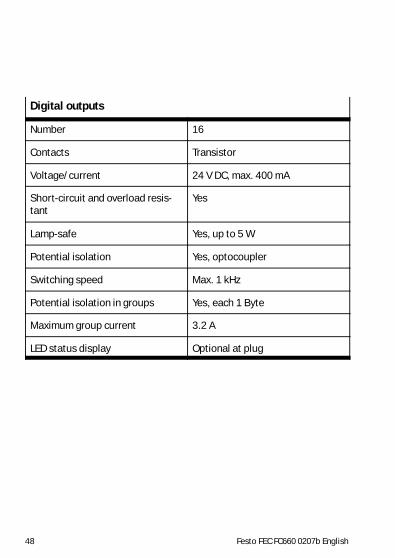
Digital outputs
Number 16
Contacts Transistor
Voltage/current 24 V DC, max. 400 mA
Short-circuit and overload resis-tant
Yes
Lamp-safe Yes, up to 5 W
Potential isolation Yes, optocoupler
Switching speed Max. 1 kHz
Potential isolation in groups Yes, each 1 Byte
Maximum group current 3.2 A
LED status display Optional at plug

Festo FEC FC660 0207b English 49
Analog Inputs
Number of Inputs 3
Signal range 0 ... 20 mA
Max. permissible input current(The automatic overload protection sets
the current input on high resistance after20 ms.)
24 mA
Resolution 12-bit
Absolute precision (0 ... 55°C) ±0,6 %
Absolute precision (25°C) ±0,4 %
Input resistance– (For diagnosis and tests a current
measurement is necessary. Due to thenon-linear impedance of the FEC-in-
ternal load, measuring the voltage ap-plied to the inputs would result in in-
accurate measurements).
330 R at 20 mA360 R at 15 mA400 R at 10 mA470 R at 7 mA620 R at 4 mA940 R at 2 mA

Festo FEC FC660 0207b English50
Analog Inputs
System input transmission time active communication interfacesno 8 msExt 11 msEthernet 13 msExt and Ethernet 14 ms
Power Consumption of the analogfunctional unit– (The supply of the analog functional
unit is required at the analog inputs if
the ”SPS-safety” is activated.)
max 0.1 WVoltage range 24 V DC+ 25%/-15%max. acceptable short timebreak ‹1 ms
Cable length for supply of theanalog functional unit
10 m
Cable length of the analog inputs 30 m (shielded)
Electrical isolationAnalog channel to– Analogchannel– Supply of the analog output
modules– Remaining signal paths
No
NoYes, if the analog functional unit issupplied with isolated voltage

Festo FEC FC660 0207b English 51
Analog Output
Number of Outputs 1
Signal range 0 ... 20 mA
Open-circuit voltage Corresponds to the power supplyof the analog functional unit
Resolution 12-bit
Absolute precision (0 ... 55°C) ±0.6 %
Absolute precision (25°C) ±0.4 %
Load impedence (ohmig load) max. 600 Ohm
System output transmission time active communication interfacesno 9 msExt 10 msEthernet 10 msExt and Ethernet 12 ms
Power consumption of the analogfunctional unit
max 0.7 WVoltage range 24 V DC +25%/-15%max. acceptable short timebreak ‹ 1ms

Festo FEC FC660 0207b English52
Analog Outputs
max. current consumption 24 VDC for supply of the analog func-tional unit
approx. 25 mA
Cable length for supply of theanalog functional unit
10 m
Cable length of the analog out-puts
30 m (shielded)
Electrical isolationAnalog channel to– Analogchannel– Supply of the analog output
modules– Remaining signal paths
No
NoYes, if the analog functional unit issupplied with isolated voltage.

Festo FEC FC660 0207b English 53
Rotary switch
Number 1
Positions 16
STOP/RUN 0 = Stop and 1 ... F = RUN
Serial interface
Number 2
Connection RJ12 socket
Characteristic Serial, asynchronous, TTL level,not galvanically separated
When used as RS232c SM14 or SM15 required
SM14/15 connection assignment TxD, RxD, RTS, CTS
When used as a programminginterface
9600 Baud, 8/N/1
When used as universal interface:COM
300 ... 9600 Baud, 7N1, 7E1, 7O1,8N1, 8E1, 8O1
When used as universal interface:EXT
300 ... max 115000 Baud, 7N1,7E1, 7O1, 8N1, 8E1, 8O1

Festo FEC FC660 0207b English54
Ethernet
Number 1
Bus interface IEEE802.3 (10Base T)
Data transfer speed 10 MBit/s
Connecting plug RJ45
Protocols supported TCP/IP, EasyIP, http u. U. http
Status display
Combined Link/Traffic LED Link: lights continuously - greenTraffic: LED flashes - green
Power LED Supply voltage indicator - green
Status LED Run-green /Stop-orange /Error-red