february 2017, volume 4, issue 02 jetir (issn 2349 5162 ... · the design of pressure vessel has...
TRANSCRIPT
February 2017, Volume 4, Issue 02 JETIR (ISSN-2349-5162)
JETIR1702021 Journal of Emerging Technologies and Innovative Research (JETIR) www.jetir.org 95
FEA ANALYSIS OF PRESSURE VESSEL
WITHDIFFERENT TYPE OF END CONNECTIONS
Deval Nitin Bhinde1 and Rajanarsimha S.
2
1MTech CAD-CAM & Robotics,
2Facculty, Department of Mechanical Engineering
K.J. Somaiya College of Engineering,India
Abstract— Design of head in pressure vessels is a challenging task. Different types of heads or ends can be provided for a pressure
vessel. This paper deals with the Finite element analysis of Pressure vessels with different type of end closures(head) keeping the same
cylindrical volume and thickness. The desired pressure vessel is designed as per ASME standard section VIII, division I for 120 bar
pressure. In this work, a comparative study of different types of pressure vessel heads is discussed. The purpose of the work is to find out
the best possible end closure out of Torispherical head, Elliptical head, Hemispherical head and Conical head. A finite element method
based software ANSYS is used to observe the stresses in these heads.
Keywords: Pressure Vessel, end closures, finite element analysis, head, stress.
I. INTRODUCTION
Pressure vessels store large amounts of energy; the higher the operating pressure - and the bigger the vessel, the more the energy released
which in the event of a rupture will lead to higher extent of damage or disaster or danger. To prevent stress related vessel rupture and
catastrophic failure, main factors that contribute extensively to stress development must be identified and ways of how they can be mitigated
must be recognized. Head of the vessel is critical zone and an analysis can provide guidelines in selecting proper head.
Different types of heads are discussed in brief below:
Flat Heads: Flat heads or plates are the simplest type of end closures used only for small vessels. They can be used as manhole covers in low
pressure vessels and as covers for small openings.
Hemispherical Heads: A hemispherical head is the strongest shape and is capable of resisting nearly twice the pressure of a torispherical head
of the same thickness. The cost of forming a hemispherical head will be higher than that for a shallow torispherical head. The amount of
forming required to produce hemispherical shape is more, resulting in increased forming cost. As they are the expensive to form they are
reserved for high pressure applications.
Ellipsoidal Heads: Ellipsoidal heads are often used for pressures over 10 bar. In cross-section, the head is like an ellipse with its radius
varying continuously. This results in a smooth transition between the dome and the cylindrical part of the vessel. The shape of the ellipsoidal
head is defined by the ratio of the major and minor axis. A standard arrangement on vessels is the 2:1 elliptical head. Due to shallow dished
shape the forming cost is reduced.
Torispherical Heads: A torispherical shape, which is extensively used as the end closure for a large variety of cylindrical pressure vessels.
The shape is close to that of an ellipse but is easier and cheaper to fabricate. Torispherical heads are made of a dish, with a constant radius.
Joining the dish directly to the cylindrical section of the vessel leads to a rapid change in geometry, resulting in excessive local stresses. To
avoid this, a transition section (knuckle) is used between the dish and the cylinder. They are generally used for very high pressure
applications.
Conical Heads: The conical heads are widely used as bottom heads to facilitate the removal or draining of fluid. The semi-cone angle is
usually taken as 30°.
II. LITERATURE REVIEW
When modelled correctly, FEA proves to be a very useful tool to find out the stress interactions between the vessel shell and the end
closure but the operator needs to interpret the results correctly. For the validation of the FEA result, calculation of stresses by experimental
methods is also necessary. The analyst must be able to obtain an approximate solution of stresses by using a classical analytical method to
verify the FEA results. The paper deals with finite element analysis of different types of end closures and their interaction with the vessel shell
keeping the thickness and volume of shell constant. Approximation of stresses was done for the horizontal pressure vessel supported on two
saddle supports. Structural analysis was done to calculate the stresses in pressure vessel. [1] For the pressure vessels, different types of heads
or ends can be provided. A comparative study of different types of pressure vessel heads is discussed in this work. A finite element method
based software ANSYS is used to observe the stresses in these heads. Comparison of stresses in these types of heads is to be done to study the
differences in stresses and to consider the forming cost and the stresses developed. [2] This work is concerned with design of different pressure
vessel elements such as shell, torispherical head, operating nozzle, its reinforcement, on standards and codes and evolution of all components
analysed by ANSYS and Experimental setup. The aim of the study was to address the problem of pressure vessel using both experimental and
Finite Element Analysis (FEA) approach. The results obtained from both FEA models and experimental tests are compared which shows a
close agreement. [3]
III. MATERIAL PROPERTIES AND DESIGN CALCULATIONS
The design of pressure vessel has been made considering various parameters internal pressure, volume etc. based on ASME codes. The
length and diameter of the vessel have been chosen according to the codes based on the quantity of fluid to be stored.
February 2017, Volume 4, Issue 02 JETIR (ISSN-2349-5162)
JETIR1702021 Journal of Emerging Technologies and Innovative Research (JETIR) www.jetir.org 96
Sr.No. Properties Value
1. Density of material 7833Kg/m3
2. Modules of elasticity 2*105N/mm
2
3. Operating pressure 120 Bar
4. Inside diameter 1500 mm
5. Cylinder length 2500 mm
6. Ultimate tensile stress 483 N/mm2
7. Welding efficiency 1
Table 1 Material Property and Design Parameters
Design Calculations
1) Shell Calculation
Thickness (t) =
=
= 68.807 mm
2) Hemispherical Head Calculation
Thickness (t) =
=
= 32.894 mm
3) Ellipsoidal Head Calculation
Thickness (t) =
=
= 65.789 mm
4) Torispherical Head Calculation
Thickness (t) =
=
= 116.44 mm
5) Conical Head Calculation
Thickness (t) =
=
= 79.45 mm
IV. FINITE ELEMENT ANALYSIS
The finite element analysis (FEA) is a numerical technique for finding the approximate solutions to boundary value problems for partial
differential equations. Finite element analysis is a powerful tool in the field of engineering. Even though finite element analysis provides
another way of analyzing structures, it requires proper understanding of the physics of the problem and the codes being used. To find out the
stresses at the interaction between pressure vessel cylinder walls and end connectors, FEA proves to be very useful as this is not possible
using standard design codes. FEA is a useful tool, but the operator needs to be able to interpret the results properly.
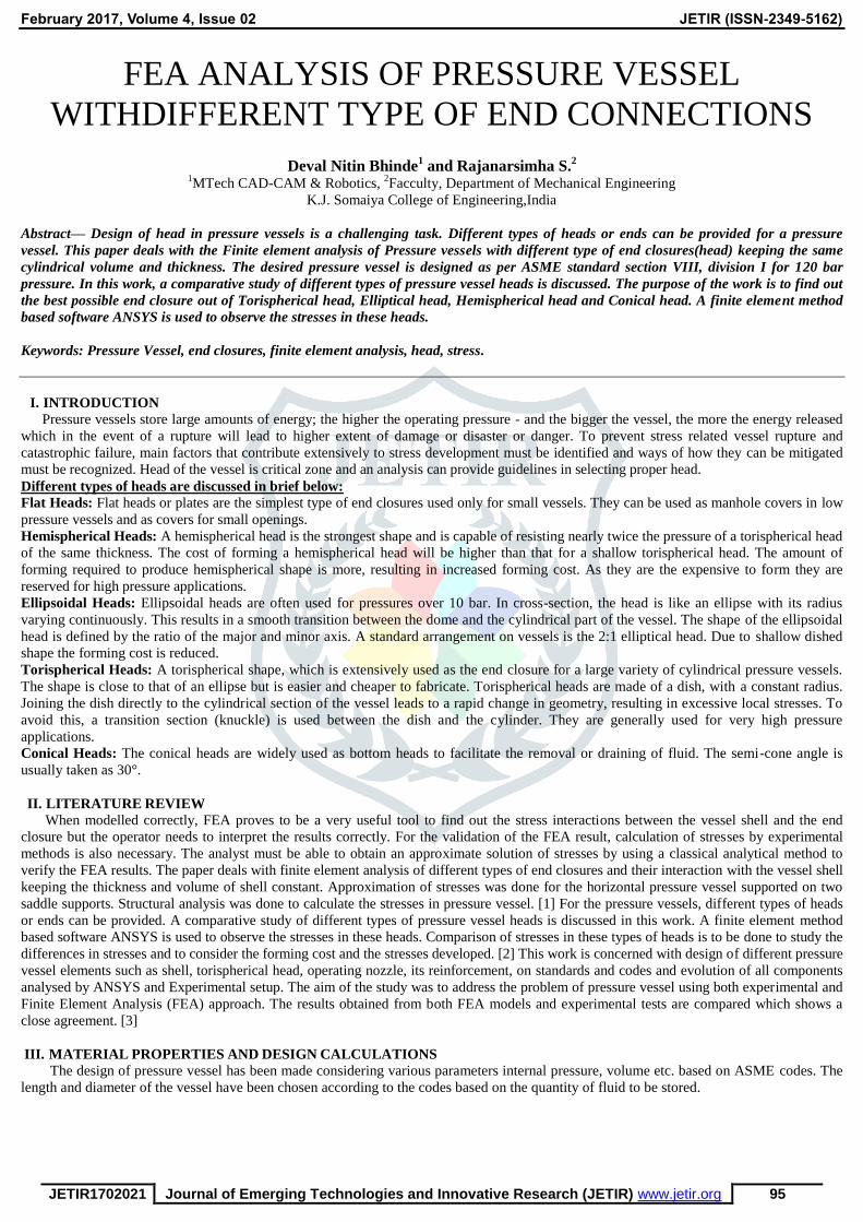
3D Cad Model of Vessel
Pressure vessel models of different condition are modelled with application of CATIA V5. The models are exported as STEP file with
solid as option. Same models are imported into ANSYS Workbench Environment.
MESHING ANSYS offers a complete set of tools for automatic mesh generation, including mapped mesh generation and free mesh generation.
Fig.1 3D CAD model
Fig.2 Meshing
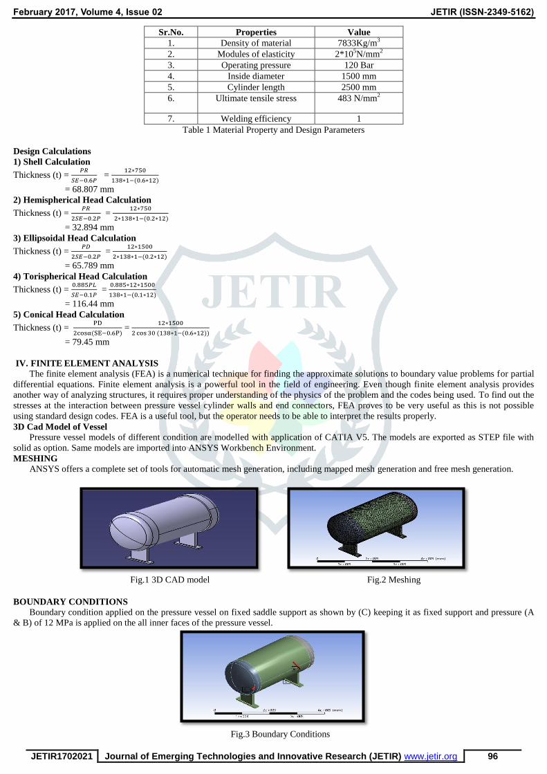
BOUNDARY CONDITIONS
Boundary condition applied on the pressure vessel on fixed saddle support as shown by (C) keeping it as fixed support and pressure (A
& B) of 12 MPa is applied on the all inner faces of the pressure vessel.
Fig.3 Boundary Conditions
February 2017, Volume 4, Issue 02 JETIR (ISSN-2349-5162)
JETIR1702021 Journal of Emerging Technologies and Innovative Research (JETIR) www.jetir.org 97
STRESS & DEFORMATION CONTOURS FROM ANALYSIS
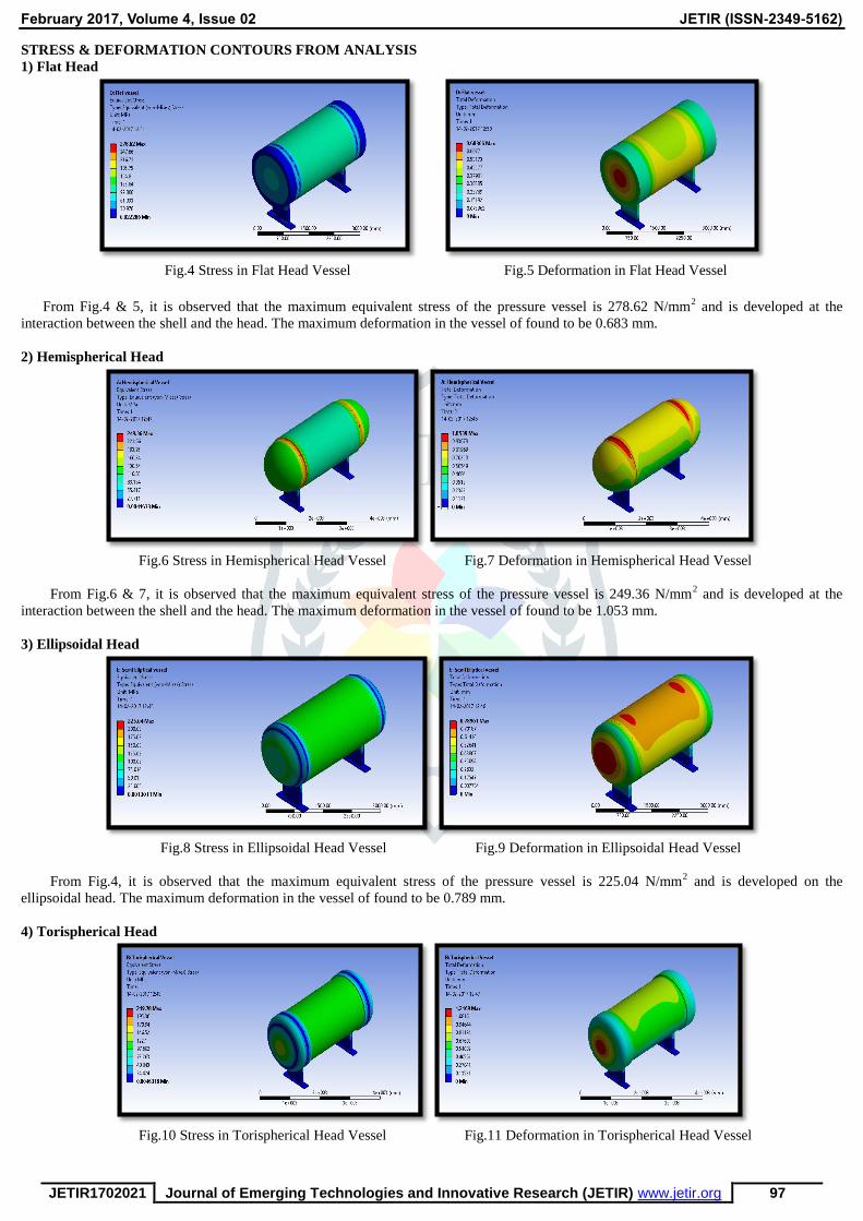
1) Flat Head
Fig.4 Stress in Flat Head Vessel
Fig.5 Deformation in Flat Head Vessel
From Fig.4 & 5, it is observed that the maximum equivalent stress of the pressure vessel is 278.62 N/mm
2 and is developed at the
interaction between the shell and the head. The maximum deformation in the vessel of found to be 0.683 mm.
2) Hemispherical Head
Fig.6 Stress in Hemispherical Head Vessel Fig.7 Deformation in Hemispherical Head Vessel
From Fig.6 & 7, it is observed that the maximum equivalent stress of the pressure vessel is 249.36 N/mm2 and is developed at the
interaction between the shell and the head. The maximum deformation in the vessel of found to be 1.053 mm.
3) Ellipsoidal Head
Fig.8 Stress in Ellipsoidal Head Vessel Fig.9 Deformation in Ellipsoidal Head Vessel
From Fig.4, it is observed that the maximum equivalent stress of the pressure vessel is 225.04 N/mm2 and is developed on the
ellipsoidal head. The maximum deformation in the vessel of found to be 0.789 mm.
4) Torispherical Head
Fig.10 Stress in Torispherical Head Vessel Fig.11 Deformation in Torispherical Head Vessel

February 2017, Volume 4, Issue 02 JETIR (ISSN-2349-5162)
JETIR1702021 Journal of Emerging Technologies and Innovative Research (JETIR) www.jetir.org 98
From Fig.4, it is observed that the maximum equivalent stress of the pressure vessel is 219.78 N/mm2 and is developed on the
Torispherical head. The maximum deformation in the vessel of found to be 1.206 mm.
5) Conical Head
Fig.12 Stress in Conical Head Vessel Fig.13 Deformation in Conical Head Vessel
From Fig.4, it is observed that the maximum equivalent stress of the pressure vessel is 233.52 N/mm2 and is developed on the conical
head. The maximum deformation in the vessel of found to be 0.750 mm.
V. RESULTS AND DISCUSSION
With the help of Finite element analysis, we have studied the actual stress distributions in the different components of pressure vessel
and the actual behavior of pressure vessel.
1) STRESS & DEFORMATION RESULTS
Sr.No Type of PV Head Eq. Stress
(MPa)
Deformation
(mm)
1. Flat Head 278.62 0.683
2. Hemispherical Head 249.36 1.053
3. Ellipsoidal Head 225.04 0.789
4. Torispherical Head 219.78 1.206
5. Conical Head 233.52 0.750
Table 2 Stress Results
Table 2 shows the variations in the von mises stresses in different type of pressure vessel heads. It is also observed that the location of
maximum stress also changes for different types of pressure vessel heads. From the software results, maximum von mises stresses are
induced flat head pressure vessel and is less in torispherical head pressure vessel.
2) CONVERGENCE RESULTS
Convergence is one of the main criteria for checking the accuracy and effectiveness of the analysis results. Generally, a finer mesh
produces more accurate results than a coarser mesh. At some point, one reaches a point where the increased mesh density fails to produce a
significant change in the results. At this point the mesh is said to be “converged.” In our case, convergence (Ellipsoidal Head Vessel) is
clearly seen at about 336035 elements when the stress value does not change significantly.
Sr.No No. of
Elements
No. of
Nodes
Eq. Stress
(MPa)
1. 2460 5249 185.86
2. 5822 12263 213.19
3. 19789 40404 211.51
4. 109292 193761 222.43
5. 336035 577880 223.64
Table 3 Convergence results
Five different end connection models were analyzed with same internal pressure of 12 MPa and same volume and the results for end
connection sub-structured models were analyzed in ANSYS.
VI. CONCLUSION & FUTURE SCOPE
Results shows that the end connection with torispherical shape is the least stressed when compared to other models. As the forming cost
of torispherical head is less as compared to hemispherical head, it can also be used for high pressure applications. On the contrary, the
thickness of torispherical head is the largest and hence the material cost increases considerably. The maximum value of stress is found in the
flat head. Hence, these types of heads are not generally used for high pressure applications even though their forming cost is less. Thus, from
the analysis, the interpretation that torispherical heads can be used for high pressure application is also validated.
For the future work, analysis of different types of heads can be done by varying the internal pressure. Different types of heads give
different results for changes in internal pressure. Moreover, the analysis can only be done taking into consideration the external loads like
wind load and weight of the vessel which has been neglected in this study.

February 2017, Volume 4, Issue 02 JETIR (ISSN-2349-5162)
JETIR1702021 Journal of Emerging Technologies and Innovative Research (JETIR) www.jetir.org 99
REFERENCES
[1] Digvijay Kolekar and Jewargi S.S, “Stress Analysis of Pressure Vessel with Different Type of End Connections by FEA”,
International Journal of Innovative Research in Science, Engineering and Technology, Vol. 4, Issue 5, pp. 2769-2775, May 2015.
[2] Sourabh Lawate and B.B. Deshmukh, “Analysis of Head of Pressure Vessel”, International Journal of Innovative Research in
Science, Engineering and Technology, Vol. 4, Issue 2, pp. 759-765, February 2015.
[3] Dr. M.M. Patil and Dr. Lokesh Bajpai, “Design, Analysis and Experimental Verification of Torispherical Head and Toriconical
Bottom Pressure Vessel”, International Journal of Innovative Science, Engineering & Technology, Vol. 1, Issue 10, pp. 423-427,
December 2014.
[4] Pavo Balicevic, Drazan Kozak and Tomislav Mrcela, “Strength of Pressure Vessels with Ellipsoidal Heads”, Stronjniski vestnik –
Journal of Mechanical Engineering, Issue 10, pp. 685-692, 2008
[5] Dhanaraj and Dr. M.V. Mallikarjuna, “Design and Stress Analysis of a Cylinder with Closed ends using ANSYS”, International
Journal of Engineering Research and Applications, Vol. 5, Issue 4(Part 6), pp. 32-38, April 2015.
[6] Apurva R. Pendbhaje, Mahesh Gaikwad, Nitin Deshmukh and Rajkumar Patil, “Design and Analysis of Pressure Vessel”,
International Journal of Innovative Research in Technology & Science, Vol. 2, Number 3, pp. 28-34.
[7] Digvijay Kolekar and Jewargi S.S, “Stress Analysis of Pressure Vessel with Different Type of End Connections – A Review”,
International Journal of Science, Engineering and Technology Research, Vol. 3, Issue 12, pp. 3460-3462, December 2014.
[8] M.V. Joshi and V.V. Mahajan, “Process Equipment Design”, Macmillan India Limited, Third Edition, 1996.
[9] ASME Boiler and Pressure Vessel Code (An International Code), Section VIII, Division 1.
[10] ASME Boiler and Pressure Vessel Code (An International Code), Section VIII, Division 2.