february 2014 tech skagit river bridge notes concrete · pdf filefebruary 2014 skagit river...
TRANSCRIPT

February 2014
Skagit River Bridge LightweightConcrete Girders
Tech NotesBridge and Structures Office
The Emergency Replacement On the evening of May 23, 2013, one of the truss spans supporting Interstate 5 between Burlington and Mount Vernon, Washington collapsed after being hit by an over height vehicle. Within hours of the collapse, discussions were underway at WSDOT about how best to replace the collapsed span, and how to restore traffic as quickly as possible. Time requirements, vertical clearance requirements, and superstructure dead load limitations quickly became the primary guiding factors in designing the span replacement.
Minimizing traffic disruptions dictated the installation of side-by-side single lane temporary modular truss bridges (supplied by ACROW, and subsequently replaced with the permanent span). For navigational purposes, vertical clearance to the river below had to be equal to or greater than that provided by the original truss span. And, importantly, to minimize
any additional seismic inertial loads to the existing bridge substructure, the dead load of the replacement span could not exceed the dead load of the original truss span by more than 5%.
Investigation of OptionsThree options were investigated for permanent span replacement; a steel through-truss (a near duplicate of the original span), a steel plate girder span with concrete deck, and a prestressed concrete girder span with concrete deck. The steel through-truss, though light in weight and aesthetically consistent with the original bridge, was thought to be too time-consuming to fabricate and erect. The project was advertised for proposal with the assumption that the most-likely structure types for proposal were going to be the steel or concrete girder options.
WSDOT and Best Value ProposalsFour Design-Build (DB) teams submitted proposals for the permanent span replacement. Two of the proposals included steel girder replacement spans, and the remaining two proposals included prestressed concrete girder span options. WSDOT selected the best value proposal, which utilized a prestressed concrete girder deck bulb tee replacement span. Lightweight concrete was specified for the girders, diaphragms and barriers, to stay within the stipulated span dead load limitations. The concrete girder proposal chosen offered competitive initial costs, low overall life-cycle costs, the shortest girder procurement time, and the minimum closure time required to replace the temporary span with the permanent span.
Bridge Elevation replacement span

Accelerated Bridge Construction TechniquesThe WSDOT recovery plan to reconstruct the Skagit River Bridge consisted of constructing the permanent replacement span using the accelerated bridge construction technics. The permanent replacement span, composed of deck bulb tee girders made of lightweight aggregate with concrete overlay, was built adjacent to the bridge and its temporary span. The roadway was closed to traffic for a period of 19 hours while the temporary span was moved out and permanent replacement span was moved into position.
The new permanent bridge was analyzed and designed using the current LRFD Bridge Design Specifications and the WSDOT Bridge Design Manuel (BDM). The WSDOT Bridge and Structures Office provided over the shoulder reviews of the design, shop drawings, and construction submittals.
Innovation and Bridge Superstructure WeightIn order to limit the weight of superstructure, the DB Team proposed girder spacing of 7’-3”. Using 7’-3” girder spacing eliminated one line of girders from the conceptual drawings advertised for bid to reduce the total superstructure weight. The total weight of new superstructure including the lightweight concrete traffic barriers and concrete overlay was 915 tons, within the limit required by the contract.
Bridge Design Technical ConsiderationsDifferential camber and reflective cracking are the two performance challenges involved with use of deck bulb tees for long spans. In order to minimize the reflective cracking the superstructure design required: 1) use of 1 ½”of concrete overlay instead of HMA for this project, 2) use of high strength concrete closure and overlapping bars instead of welded ties.
The differential camber was adjusted using leveling beams prior to casting concrete at the closures. The predicted camber for lightweight deck bulb tee girders was 6.5”, and the measured girder cambers were slightly above the predicted camber. The Span to depth ratio of 29.5 for the new superstructure met the LRFD Bridge Design criteria for deflection.
The design compressive strength of lightweight concrete used for the deck bulb tees was 9.0 ksi, with a compressive strength of concrete at transfer of prestress of 7.0 ksi. The unit weight of lightweight concrete mix was 0.122 kcf, with unit weight of girder of 0.133 kcf for design and dead load calculations. A total of 48-0.6” diameter strands were used for the design of the girders. Temporary strands in top flange of girders were provided to minimize camber and provide stability of the girder as it was shipped from the manufacturing facility to the job site.
Bridge typical section
Girder leveling beams
Deck bulb tee girders viewed from below
Girder camber diagram
500 ton crane on river dike
Two temporary supports at 20 ft from the end of girders were provided at intermediate diaphragms locations to accommodate the bridge move as outlined below.
Replacement Span ConstructionMax J. Kuney Company (MJK) of Spokane Washington was selected as the contractor to construct the permanent replacement span. The Design-Build method was used with the goal of rapid construction.
MJK received notice to proceed on June 19 and the design phase started immediately. Fabrication of the eight bulb T-girders began July 9.
The project’s scope of work included construction of the new span adjacent to the bridge’s two temporary spans, then removal of the temporary spans and placement of the single, permanent span.
In order to do minimize closure times, a new permanent span had to be constructed on piling and bents just downstream of the temporary spans. A series of tracks had to be installed 20’ from the ends of the girders. These tracks were installed on an inner set of pile bents under the permanent span, under the newly installed temporary span, and upriver of the temporary span. The temporary span had to be rolled sideways, upriver from I-5 upon completion of the permanent span. And in the same operation of work, the permanent span had to be rolled upriver, in place of the temporary span. All of the rolling was done on this inner set of tracks as to simply roll out one bridge span and roll in another in a single road closure. After the installation of the permanent span, the temporary span and all of the piling and tracks were removed with live traffic being safely supported on the newly installed permanent span.
Girder Cranes Work from Barge SystemThe girders were set using a 500 ton crane on the river’s dike and a 200 ton crane on a Flexifloat barge system. The crane picks were quite detailed. Each pick required 19 specific moves, including passing the end of the girder from the dike to the barge crane, tucking the girder under the boom of the barge crane - while re-ballasting the barge system - and finally re-ballasting the barge as the girder was placed on the temporary bent.
A separate row of piling and bents were built to support a rail system that would be used to slide the temporary spans out, and slide the new span into place.
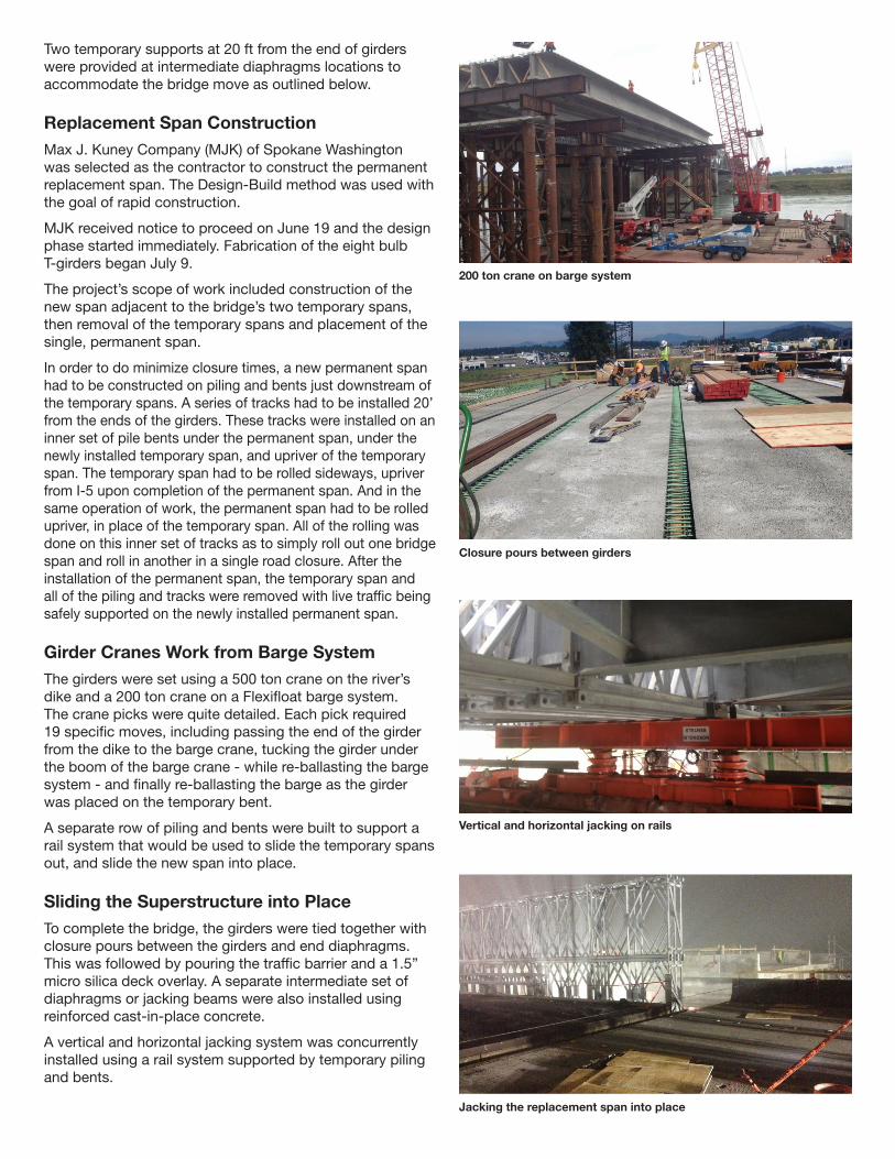
Sliding the Superstructure into PlaceTo complete the bridge, the girders were tied together with closure pours between the girders and end diaphragms. This was followed by pouring the traffic barrier and a 1.5” micro silica deck overlay. A separate intermediate set of diaphragms or jacking beams were also installed using reinforced cast-in-place concrete.
A vertical and horizontal jacking system was concurrently installed using a rail system supported by temporary piling and bents.
200 ton crane on barge system
Closure pours between girders
Vertical and horizontal jacking on rails
Jacking the replacement span into place

For More Information
Tom Baker, PEState Bridge & Structures Engineer 360-705-7207 [email protected]
Bijan Khaleghi, PhD, PE, SE State Bridge Design Engineer 360-705-7181 [email protected]
Harvey Coffman, PE, SEBridge Preservation Engineer 360-570-2556 [email protected]
DeWayne Wilson, PEBridge Management Engineer 360-705-7214 [email protected]
Bijan Khaleghi, PhD, PE, SEState Bridge Design Engineer 360-705-7181 [email protected]
Patrick Gallagher, PESenior Bridge Engineer 360-705-7162 [email protected]
Title VI Statement to Public: WSDOT ensures full compliance with Title VI of the Civil Rights Act of 1964 by prohibiting discrimination against any person on the basis of race, color, national origin or sex in the provision of benefits and services resulting from its federally assisted programs and activities. For questions regarding WSDOT’s Title VI Program contact Jonté Sulton at 360-705-7082 or [email protected].
Americans with Disabilities Act (ADA) Information: Materials can be provided in alternative formats for people with disabilities by calling Shawn Murinko at 360-705-7097 or [email protected]. Persons who are deaf or hard of hearing may contact Office of Equal Opportunity through the Washington Relay Service at 7-1-1.
14-02-0002389
For Specific Information
Washington State Department of Transportation HQ Bridge & Structures Office 7345 Linderson Way SW Tumwater, WA 98501
To complete the installation of the new span, first the temporary spans were lifted off the existing substructure and slid off onto the temporary bents upstream of the bridge. The new span was moved in a similar fashion.
Finishing UpThe overall construction started on July 12 and the new span was opened to traffic on September 15. It took just under 19 hours to swap the spans and open the freeway to traffic on the new permanent span.
To finish up the work, the temporary spans were disassembled onto the Flexifloat barge system and all of the piling was removed from the river.
Successful as the replacement of the collapsed bridge was (the number of closed days totaled only 28), there was little rest for the designers and contractors on September 15th. With the permanent replacement span in place, attention turned to the remaining three truss spans, specifically their portal and sway frame systems, and their vertical clearances. While truckers are responsible for their over-height loads, states are prudent to examine over-height hits and apply mitigation if possible. In this case that meant removing and replacing the lowest height elements of the trusses, increasing the vertical clearance across the two outside lanes, helping to extend the already long-life of the I-5 Skagit River Bridge.
Video seriesA time lapse series of the entire girder setting operation can be found at this link:
www.youtube.com/watch?v=-IdUap4_IvY
Traffic on the new replacement span
Disassembling the temporary span