features, events and processes evaluation catalogue for ... · radioactive waste management isbn...
TRANSCRIPT
Radioactive Waste Management ISBN 92-64-02148-5
Features, Events and Processes EvaluationCatalogue for Argillaceous Media
Report prepared by
Martin Mazurek(University of Bern, Switzerland)
F. Joe Pearson(Ground-Water Geochemistry, United States)
Geert Volckaert(SCK•CEN, Belgium)
and
Helmut Bock(Q + S Consult, Germany)
© OECD 2003NEA4437
NUCLEAR ENERGY AGENCYORGANISATION FOR ECONOMIC CO-OPERATION AND DEVELOPMENT
ORGANISATION FOR ECONOMIC CO-OPERATION AND DEVELOPMENT
Pursuant to Article 1 of the Convention signed in Paris on 14th December 1960, and which came into force on30th September 1961, the Organisation for Economic Co-operation and Development (OECD) shall promote policiesdesigned:
− to achieve the highest sustainable economic growth and employment and a rising standard of living inMember countries, while maintaining financial stability, and thus to contribute to the development of theworld economy;
− to contribute to sound economic expansion in Member as well as non-member countries in the process ofeconomic development; and
− to contribute to the expansion of world trade on a multilateral, non-discriminatory basis in accordance withinternational obligations.
The original Member countries of the OECD are Austria, Belgium, Canada, Denmark, France, Germany, Greece,Iceland, Ireland, Italy, Luxembourg, the Netherlands, Norway, Portugal, Spain, Sweden, Switzerland, Turkey, the UnitedKingdom and the United States. The following countries became Members subsequently through accession at the datesindicated hereafter: Japan (28th April 1964), Finland (28th January 1969), Australia (7th June 1971), New Zealand (29thMay 1973), Mexico (18th May 1994), the Czech Republic (21st December 1995), Hungary (7th May 1996), Poland (22ndNovember 1996), Korea (12th December 1996) and the Slovak Republic (14 December 2000). The Commission of theEuropean Communities takes part in the work of the OECD (Article 13 of the OECD Convention).
NUCLEAR ENERGY AGENCY
The OECD Nuclear Energy Agency (NEA) was established on 1st February 1958 under the name of the OEECEuropean Nuclear Energy Agency. It received its present designation on 20th April 1972, when Japan became its firstnon-European full Member. NEA membership today consists of 28 OECD Member countries: Australia, Austria, Belgium,Canada, Czech Republic, Denmark, Finland, France, Germany, Greece, Hungary, Iceland, Ireland, Italy, Japan, Luxembourg,Mexico, the Netherlands, Norway, Portugal, Republic of Korea, Slovak Republic, Spain, Sweden, Switzerland, Turkey, theUnited Kingdom and the United States. The Commission of the European Communities also takes part in the work of theAgency.
The mission of the NEA is:
− to assist its Member countries in maintaining and further developing, through international co-operation, thescientific, technological and legal bases required for a safe, environmentally friendly and economical use ofnuclear energy for peaceful purposes, as well as
− to provide authoritative assessments and to forge common understandings on key issues, as input togovernment decisions on nuclear energy policy and to broader OECD policy analyses in areas such as energyand sustainable development.
Specific areas of competence of the NEA include safety and regulation of nuclear activities, radioactive wastemanagement, radiological protection, nuclear science, economic and technical analyses of the nuclear fuel cycle, nuclear lawand liability, and public information. The NEA Data Bank provides nuclear data and computer program services forparticipating countries.
In these and related tasks, the NEA works in close collaboration with the International Atomic Energy Agency inVienna, with which it has a Co-operation Agreement, as well as with other international organisations in the nuclear field.
© OECD 2003Permission to reproduce a portion of this work for non-commercial purposes or classroom use should be obtained through theCentre français d’exploitation du droit de copie (CCF), 20, rue des Grands-Augustins, 75006 Paris, France, Tel. (33-1) 44 0747 70, Fax (33-1) 46 34 67 19, for every country except the United States. In the United States permission should be obtainedthrough the Copyright Clearance Center, Customer Service, (508)750-8400, 222 Rosewood Drive, Danvers, MA 01923,USA, or CCC Online: http://www.copyright.com/. All other applications for permission to reproduce or translate all or partof this book should be made to OECD Publications, 2, rue André-Pascal, 75775 Paris Cedex 16, France.
3
FOREWORD
Argillaceous media are being considered throughout the OECD/NEA member countries aspotential host rocks for the final, safe, near-surface or at depth disposal of radioactive waste, and/or asa major constituent of the repository system in which waste will be emplaced. These media haveindeed a number of favourable generic properties, e.g. homogeneity, low water flow, chemicalbuffering, propensity for plastic deformation and self-sealing of fractures, and marked capacity tochemically retard the migration of radionuclides.
For evaluating these geological media and notably for quantitatively assessing the potentialmigration of radionuclides to the environment, not only site-specific data from a site characterisationprogramme are required, but also a sound understanding of the basic physical and chemical processesthat govern water, gas and solute transport through them. An important stage of the performanceassessment is the identification and documentation of the features, events and processes that may berelevant to long-term safety.
In this context, the Working Group on the Characterisation, the Understanding and thePerformance of Argillaceous Rocks as Repository Host Formations (known as “Clay Club”) launchedthe FEPCAT (Features, Events and Processes CATalogue for argillaceous media) project in late 1998.The FEPCAT project aims at providing, for each FEP, a critical overview of conclusions and keyreferences related to its current understanding and its potential impact on the long-term performance ofthe geosphere barrier, and information on ongoing and planned work. Experimental information (field,laboratory, numeric) provided by the funding organisations was the primary source of data.
Specifically, the main objectives were as follows:
• To derive a list of FEPs which are specific to argillaceous media. Only FEPs deemedrelevant were to be included.
• To provide an overview of past, ongoing and planned in situ and laboratoryexperiments.
• To make a link between site investigations and their application in performanceassessment, and to provide a scientific background for the assessment of geosphereperformance.
• To define future priorities with regard to a better understanding of argillaceous media.
• To define terms whose connotation is different in different countries or scientificdisciplines, and to link the radwaste terminology to general scientific usage.
The present document provides the results of work performed by an Expert Group to developa FEPs database related to argillaceous formations, whether soft or indurated. It describes themethodology for the work performed, provides a list of relevant FEPs, summarises the knowledge oneach of them, gives general conclusions and identifies priorities for future work.
A pdf version is available on the following website: http://www.nea.fr/html/rwm/clayclub.html.
4
Acknowledgements
The national organisations represented within the Working Group on the Characterisation,the Understanding and the Performance of Argillaceous Rocks as Repository Host Formations (knownas “Clay Club”) and the NEA wish to express their gratitude to the authors of this report: M. Mazurek(Switzerland), F. J. Pearson (USA), G. Volckaert (Belgium) and H. Bock (Germany).
This project was supported by a consortium of national organisations: Andra (France),Enresa (Spain), IRSN (France), JNC (Japan), Nagra (Switzerland), Nirex (United Kingdom),Ondraf/Niras and SCK•CEN (both Belgium). These organisations are thanked for their financialsupport and for their technical input.
The following external experts are also thanked for their contribution by filling inquestionnaires for selected FEPs: J. Katsube (Canada), B. Krooss (Germany), C. Neuzil (USA), Puramand Mecsek Ore Environment (both Hungary). T. Sumerling (United Kingdom) is acknowledged forcontributing to the structuring of the FEPs list.
Valuable technical and administrative support was provided by J. C. Mayor (Chairman of theFEPCAT Steering Group, Enresa), P. Lalieux (Clay Club Chairman, Ondraf/Niras), Marc Thury (pastClay Club Chairman, Nagra) and Sylvie Voinis (NEA secretariat). A review of a previous draft of thisreport was also provided by GRS (Germany).
Finally, Nagra is thanked for hosting the Expert Group meetings.
5
TABLE OF CONTENTS
Foreword ........................................................................................................................................ 3
Section I: Framework and Lessons Learned ........................................................................... 9
1. Introduction ......................................................................................................... 11
2. Presentation of Sites Considered in the Project .................................................. 17
3. Derivation and Presentation of the FEPs List ..................................................... 21
4. Questionnaire Structure....................................................................................... 31
5. Quality and Number of Answers to the Questionnaire ....................................... 33
6. Documentation of Unanswered FEPs (“Blank” FEPs) ....................................... 35
7. Insights Based on the Compilation...................................................................... 39
8. Classification of FEPs According to State of Knowledge and PotentialRelevance for Performance Assessment ............................................................. 51
9. Conclusions ......................................................................................................... 59
10. Correlation of FEPs from the FEPCAT Project with the NEA FEPs Database .. 69
Section II: FEPs Compilation ..................................................................................................... 79
1. Advection/Dispersion.......................................................................................... 83
2. Size and Geometry of the Host Rock and of Surrounding Units,Path Length ......................................................................................................... 87
3. Migration Pathways, Including Heterogeneity and Anatomy ............................. 95
4. Undetected Geological Features.......................................................................... 101
5. Hydraulic Potentials and Gradients in the Host Rock, IncludingBoundary Conditions .......................................................................................... 105
6. Hydraulic Properties of the Host Rock................................................................ 111
7. Units Over- and Underlying the Host Formation: Local and RegionalHydrogeologic Framework ................................................................................. 115
8. Diffusivity ........................................................................................................... 119
9. Connected Matrix Porosity.................................................................................. 125
10. Ion Exclusion ...................................................................................................... 131
11. Surface Diffusion ................................................................................................ 135
6
12. Colloid Formation, Transport and Filtration ....................................................... 139
13. Flow-wetted Surface and Accessibility of Matrix............................................... 141
14. Lithology, Mineralogy of Rocks and Fracture Infills.......................................... 143
15. Natural Organics, Complexation......................................................................... 151
16. Mineral-surface Area........................................................................................... 159
17. Pore- and Fracture-water Composition ............................................................... 163
18. Dissolution/Precipitation of Solid Phases ........................................................... 169
19. Solid Solutions/Co-precipitation ......................................................................... 173
20. Ion Exchange....................................................................................................... 179
21. Surface Complexation ......................................................................................... 183
22. Thermodynamic and Kinetic Modelling Data..................................................... 187
23. Palaeo-hydrogeology of the Host Formation and of Embedding Units .............. 191
24. Evolution of Pore-fluid (Water and Gas) Chemistry and Mineralogyin the Host Formation and in Embedding Units.................................................. 195
25. Water Residence Times in the Host Formation................................................... 201
26. Oxidation of the Host Rock................................................................................. 205
27. Redox Buffering Capacity of the Host Rock....................................................... 209
28. Effects of Repository Components on Pore-water Chemistryin the Host Rock.................................................................................................. 213
29. Interaction of Hyperalkaline Fluids and Host Rock............................................ 215
30. Organics from Waste and their Effect on Transport Propertiesof the Host Rock.................................................................................................. 221
31. Thermal Effects on Mineral Stability and Pore-water Composition ................... 225
32. Thermal Rock Properties..................................................................................... 229
33. Thermally Induced Consolidation of the Host Rock........................................... 233
34. Geomechanical Stability ..................................................................................... 237
35. Size and Structure of the EDZ............................................................................. 241
36. Effects of Bentonite Swelling on the Host Rock................................................. 245
37. Geomechanical Rock Properties ......................................................................... 249
38. Hydraulic Properties of the EDZ......................................................................... 255
39. State of Saturation of the EDZ and Desiccation Cracking.................................. 259
40. Coupled Thermo-hydro-mechanic Processes...................................................... 263
41. Swelling............................................................................................................... 267
42. Self-sealing.......................................................................................................... 271
43. Off-diagonal Onsager Processes Except Chemical Osmosis .............................. 277
7
44. Chemical Osmosis............................................................................................... 281
45. Gas Dissolution and Chemical Interactions Between Gas and Pore-water ......... 285
46. Gas Migration Through the Primary Porosity (Matrix, Natural Fractures)......... 289
47. Gas Migration Through Stress-induced Porosity(Gas Fracs, Pathway Dilation) ............................................................................ 293
48. Gas-induced Transport in Water ......................................................................... 299
49. Microbiological Perturbations............................................................................. 303
50. Past Burial History .............................................................................................. 307
51. Present and Future Geothermal Regime and Related Processes ......................... 311
52. Future Changes in Hydrochemistry of the Host Rock and of SurroundingFormations (e.g. Due to Out-diffusion, Water-rock Interactions, Uplift) ........... 313
53. Past Deformation Events..................................................................................... 317
54. Future Fault (re)Activation, Changes in Migration Pathways;Changes of Hydraulic Parameters; Flow Events................................................. 321
55. Present-day Stress Regime .................................................................................. 325
56. Future Stress Regime .......................................................................................... 331
57. Geomechanical Effects of Erosion/Unloading .................................................... 333
58. Consolidation Due to Burial................................................................................ 337
59. Future Evolution of Hydraulic Potentials and Gradients(e.g. Due to Erosion or Burial) ............................................................................ 341
Section III: References .................................................................................................................. 345
List of Tables
Table 1. System components of a deep geological repository .................................................. 23
Table 2. Structured FEPs list..................................................................................................... 27
Table 3. Documentation of FEPs left blank in the questionnaires ............................................ 35
Table 4. Documentation of FEPs left blank: FEPs with 3 or more answers stating thatthe FEP may be important, while information of the FEP is limited .......................... 36
Table 5. Documentation of FEPs left blank: FEPs with 2 answers stating that the FEPmay be important, while information of the FEP is limited........................................ 37
Table 6. List of FEPs that are useful for upscaling other FEPs in argillaceous rocks .............. 40
Table 7. Classification of FEPs according to state of knowledge and PA relevance................ 53
Table 8. Classification of FEPs according to state of knowledge and PA relevance:Selection of those FEPs that are regarded as relevant but not sufficientlywell understood in diffusion-dominated systems........................................................ 60
Table 9. Classification of FEPs according to state of knowledge and PA relevance inadvection-dominated systems ..................................................................................... 61
8
Table 10. Potential areas for future studies in argillaceous media.............................................. 65
Table 11. Extract of the NEA FEPs database with FEPs that are of concern withinthe scope of the FEPCAT project ............................................................................... 70
Table 12. Possible allocation of FEPCAT FEPs to FEPs from the NEA database..................... 71
List of Figures
Figure 1. Approaches for the derivation of FEPs lists................................................................ 22
Figure 2. System components of a repository environment ....................................................... 24
Figure 3. Number of answers per FEP received by the Expert Group ....................................... 34
9
SECTION I
Framework and Lessons Learned


11
1. INTRODUCTION
The FEPCAT (Features, Events and Processes CATalogue for argillaceous media) projectwas launched by the OECD/NEA Clay Club in late 1998. This initiative was motivated by the growinginternational interest in argillaceous formations as hosts of geological repositories for radioactivewaste. A number of sites are currently being investigated, and underground research laboratories are inoperation. FEPCAT was funded by Andra (France), Enresa (Spain), IRSN (France), JNC (Japan),Nagra (Switzerland), Nirex (United Kingdom), Ondraf/Niras (Belgium) and SCK•CEN (Belgium).Each of these organisations nominated a delegate to the Steering Group, which was chaired byJ.C. Mayor (Enresa). The technical work was carried out by the Expert Group, i.e. the authors of thisreport, under the co-ordination of Martin Mazurek. The project was subdivided into the followingstages:
1. Definition of a list of FEPs (Features, Events, Processes) by the Expert Group. Design ofa questionnaire prompting all participating organisations for technical input.
2. Provision of technical input in questionnaire format by all participating organisations.
3. Compilation and synthesis of the information by the Expert Group.
Further information for a small number of FEPs was provided by External experts,i.e. scientists with relevant knowledge of selected aspects of clay science. These included J. Katsube(Canada), B. Krooss (Germany), C. Neuzil (USA) and the Hungarian team of Mecsek OreEnvironment and Puram.
The Expert Group consisted of the following members:
Name Affiliation Expertise
Helmut Bock Q + S Consult, BadBentheim, Germany
Geomechanics. Mechanical interpretation ofgeological structures. In situ stress regimes andtheir measurement. Laboratory and field testing.Engineering of sub-surface structures andperformance assessment.
Martin Mazurek Rock-Water Interaction,Institute of GeologicalSciences, University ofBern, Switzerland
Interactions between minerals, aqueous fluids andgases. Structural geology and relationship tohydrogeology. Impact of geologic systemproperties and processes on theperformance/safety of the geologic barrier.
12
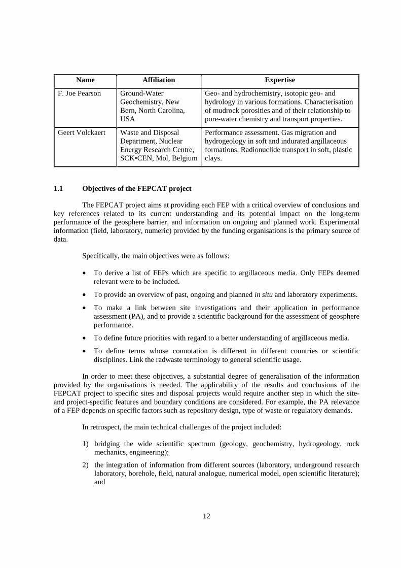
Name Affiliation Expertise
F. Joe Pearson Ground-WaterGeochemistry, NewBern, North Carolina,USA
Geo- and hydrochemistry, isotopic geo- andhydrology in various formations. Characterisationof mudrock porosities and of their relationship topore-water chemistry and transport properties.
Geert Volckaert Waste and DisposalDepartment, NuclearEnergy Research Centre,SCK•CEN, Mol, Belgium
Performance assessment. Gas migration andhydrogeology in soft and indurated argillaceousformations. Radionuclide transport in soft, plasticclays.
1.1 Objectives of the FEPCAT project
The FEPCAT project aims at providing each FEP with a critical overview of conclusions andkey references related to its current understanding and its potential impact on the long-termperformance of the geosphere barrier, and information on ongoing and planned work. Experimentalinformation (field, laboratory, numeric) provided by the funding organisations is the primary source ofdata.
Specifically, the main objectives were as follows:
• To derive a list of FEPs which are specific to argillaceous media. Only FEPs deemedrelevant were to be included.
• To provide an overview of past, ongoing and planned in situ and laboratory experiments.
• To make a link between site investigations and their application in performanceassessment (PA), and to provide a scientific background for the assessment of geosphereperformance.
• To define future priorities with regard to a better understanding of argillaceous media.
• To define terms whose connotation is different in different countries or scientificdisciplines. Link the radwaste terminology to general scientific usage.
In order to meet these objectives, a substantial degree of generalisation of the informationprovided by the organisations is needed. The applicability of the results and conclusions of theFEPCAT project to specific sites and disposal projects would require another step in which the site-and project-specific features and boundary conditions are considered. For example, the PA relevanceof a FEP depends on specific factors such as repository design, type of waste or regulatory demands.
In retrospect, the main technical challenges of the project included:
1) bridging the wide scientific spectrum (geology, geochemistry, hydrogeology, rockmechanics, engineering);
2) the integration of information from different sources (laboratory, underground researchlaboratory, borehole, field, natural analogue, numerical model, open scientific literature);and
13
3) the establishment of a link between data acquisition and process understanding on theone hand and the use of this information in performance assessment on the other hand.
The FEPCAT project does not claim to provide an exhaustive characterisation for each FEP,covering the complete spectrum of all scientific and PA-related aspects. By the nature of its structureand philosophy, it includes expert judgement to some degree and, for the application to a disposalproject, requires the consideration of system-specific boundary conditions. The emphasis is onintegration and knowledge management (“guide book”), not on the details of interest to specialists invery specific fields. FEPCAT has not been designed to provide a catalogue of quantitative values to beused directly as input to PA calculations.
1.2 Scope
The FEPCAT project:
• focuses on FEPs related to deep geological disposal and covers all types of argillaceousrocks, whether soft or indurated;
• is independent of the type of radioactive waste disposal planned (spent fuel, vitrifiedhigh-level waste, TRU waste, low-level waste);
• focuses on the geosphere (including the affected field and the excavation-disturbedzone, i.e. all effects related to the existence of the repository) but excludes theengineered barriers per se;
• considers only FEPs with post-closure effects over a time period in the order of 1 Ma;
• excludes waste retrieval and all human activities after the closure of the repository;
• focuses on a limited number of high-probability FEPs but disregards FEPs deemed lessimportant or unlikely to occur. Technical detail is more important than completeness;
• focuses on FEPs that have specific characteristics in argillaceous rocks;
• considers each FEP in isolation (no scenario analysis);
• has no ambition to judge national programmes.
1.3 Closing dates
Most of the information that was provided by the participating organisations dates from theyear 2000. The Expert Group included more recent information wherever it was easily available.However, no formal update could be performed, and the completeness of the most recent informationcannot be guaranteed at this stage. Relevant reports that became available during the final stages of theFEPCAT project and thus were not considered in full include:
SAFIR-2 (Boom Clay, Belgium; Ondraf/Niras, 2002)
Référentiel géologique (Callovo-Oxfordian, France; Andra, 1999a)
Opalinus Clay synthesis (Switzerland; Nagra, 2002)
Geochemical synthesis of the Mont Terri Underground Laboratory (Opalinus Clay,Switzerland; Pearson et al., 2003).
14
1.4 Definitions and abbreviations
Advection-dominated transport In an argillaceous formation, advection may become thedominant transport process if preferential flow along fractureswithin the formation occurs over the spatial scales considered inPAs. This means that advection-dominated transport isimportant if a formation contains a connected fracture networkand if the fractures have, at least episodically, a transmissivitywell above that of the unfractured rock mass.
Diffusion-dominated transport Diffusion is the dominant transport mechanism (over spatialscales considered in PAs) in argillaceous formations that aredevoid of connected fracture networks and in fracturedformations where fracture transmissivity is similar to that of theunfractured rock matrix (e.g. due to self-sealing processes).
EDZ Excavation-disturbed zone. In this report, this term relates to thezone around underground openings where plastic (irreversible)and/or elastic (reversible) deformation took place in response tothe excavation. Thus the term “EDZ” as used here does notrefer exclusively to the zone where macroscopic fracturesdeveloped but to a larger region. There is no universallyaccepted definition, and the matter is discussed in NEA(2002b).
FEP Feature, event or process potentially relevant for the evaluationof long-term safety of a geological waste repository (see alsoNEA, 2000).
Performance assessment (PA) Analysis of the performance of the system concept, with theaim of developing confidence that the system will (or can bedesigned to) perform within acceptable bounds. May include,but is not limited to, a range of quantitative analyses ofradionuclide release from, and migration through, individualsystem components.
Safety assessment Process of evaluating long-term performance, compliance withacceptance guidelines and confidence in the safety indicated bythe assessment results. Performance assessment is a necessaryinput to safety assessment.
Safety case Collection of arguments, at a given stage of repositorydevelopment, in support of the long-term safety of therepository. A safety case comprises the findings of a safetyassessment and a statement of confidence in these findings. Itshould acknowledge the existence of any unresolved issues andprovide guidance for work to resolve these issues in futuredevelopment stages. A safety case is the end product of a safetyassessment.
15
Clay, shale & lithologic terms There is no generally accepted terminology of argillaceoussediments and sedimentary rocks (see also discussion inHorseman et al., 1996, ch. 2.1). Existing classification schemesuse grain size, degree of induration and texture (e.g. lamination,fissility) as criteria. However, they are not all consistent(compare e.g. Potter et al., 1980 and Blatt et al., 1980) and,more importantly, many of the terms coined in thoseclassifications are not currently used (e.g. “claymud”,“mudshale”). Aplin et al. (1999) discuss these difficulties andpropose to use the terms “mud” and “mudstone” in a broadsense, including all clastic sediments and sedimentary rockswhere grain size is primarily <62.5 µm. The term “clay” refersto a non-indurated clastic sediment where >66% of the rock hasa grain size below 4 µm, and “claystone” is the induratedanalogon. “Shale” is not defined in a consistent way, but issometimes used as a synonym of “argillaceous sediment andsedimentary rock”, and sometimes to describe an induratedargillaceous sedimentary rock only. There is a generalagreement that “argillite” describes a highly indurated, low-grade metamorphic argillaceous rock.
In this report, the term “clay” will be used to address weaklyconsolidated lithologies rich in clay minerals, such as the Boomor Yper Clays in Belgium. In contrast, “shale” will be used todescribe more strongly consolidated units, such as the Toarcian-Domerian at Tournemire (France). It also needs to be notedthat, for historic reasons, formation names are not necessarilyconsistent with current lithological terminology, e.g. in the caseof Opalinus Clay or the Boda Clay Formation (which will beaddressed as shales in this report).


17
2. PRESENTATION OF SITES CONSIDERED IN THE PROJECT
2.1 Callovo-Oxfordian at Bure, France
In the eastern part of the Paris Basin, Andra is investigating a site near Bure (also called“Site Meuse-Haute Marne” or “Site de l'Est”), mainly targeting a flat-lying, ca. 130 m thickargillaceous formation of Callovo-Oxfordian age at 420-550 m below surface. Three deep boreholeswere drilled and investigated. These investigations provided the basis for an extensive report(Référentiel géologique). Currently, shaft-sinking activities are underway for an underground researchlaboratory in the Callovo-Oxfordian formation. Should future investigations corroborate the suitabilityof the site, it is envisaged to build a repository for high-level waste.
Investigations performed mainly by: Andra, France. Key reference: Andra (1999a).
2.2 Toarcian-Domerian at Tournemire, France
In 1989-1990, IRSN initiated in situ research in argillaceous formations. An undergroundresearch laboratory was built in 2 galleries excavated from a former railway tunnel near Tournemire(Aveyron, southern France). The tunnel is 110 years old and 1885 m long. It penetrates a flat lying,250 m thick Liassic argillaceous series (Domerian and Toarcian marls and shales).
The Tournemire project aims at generic studies related to the disposal of radioactive waste.The main geological, stratigraphic, tectonic and hydrogeological characteristics of the site are studied.The research programme deals mainly with the hydrogeological properties, in order to characterisefluid flow and solute transport through the argillaceous formation and to quantify the relevantprocesses in numeric models.
The site is not under consideration for a real radioactive waste repository, but providessupport for generic studies for this purpose.
Investigations performed mainly by: IRSN, France. Key references: Boisson et al. (1998),Cabrera et al. (2001).
2.3 Spanish Reference Clay, Spain
The Spanish Reference Clay refers to one of the numerous argillaceous formations retainedin Spain for future characterisation studies when so decided by the Spanish authorities.
Investigations performed mainly by: Enresa, Spain. Key reference: Enresa (1999).

18
2.4 Opalinus Clay at Mont Terri, Switzerland
The Mont Terri underground research laboratory is located in north-western Switzerland(Canton Jura) and consists of a tunnel parallel to a security tunnel and to the main tunnel of amotorway across the Mont Terri anticline in the Folded Jura Mountains. It is located in Opalinus Clay,a middle Jurassic marine shale formation. The formation is over-consolidated and ca. 270 m belowsurface at laboratory level. Research was started 1996 and will be documented in synthesis reports ongeochemistry (available), hydrogeology and rock mechanics (in preparation). In future, the main focuswill be long-term experiments.
Investigations performed mainly by: Mont Terri international consortium. Key references:Thury & Bossart (1999), Pearson et al. (2003).
2.5 Opalinus Clay in the Zürcher Weinland, Switzerland
In 1994, the Opalinus Clay (a Middle Jurassic marine shale formation) was identified as thepriority sedimentary host rock option for the disposal of spent fuel and vitrified high-level waste inSwitzerland, and the Zürcher Weinland (north-east Switzerland) as the first-priority area for site-related investigations. Detailed characterisation of the host rock and the potential siting area followedafter 1994. The key elements of this research programme were a 3-D seismic campaign in the ZürcherWeinland covering an area of around 50 km2, an exploratory borehole (Benken), experiments as partof the international research programme in the Mont Terri underground research laboratory (CantonJura), comparative regional studies on the Opalinus Clay including deep boreholes in the near and farvicinity of the siting area, and comparisons with clay formations that are under investigation in othercountries in connection with geological disposal.
Investigations performed mainly by: Nagra. Key reference: Nagra (2002).
2.6 Boom Clay at Mol, Belgium
The Boom Clay under the nuclear site of Mol/Dessel in the north-east of Belgium isconsidered as the Belgian reference host formation for the methodological study of the disposal oflong lived medium and high level radioactive waste in deep clay layers. The first characterisationworks under the site were launched in 1975 by the Nuclear Energy Research Centre of Mol(SCK•CEN). Since that time three sampled deep drillings with extensive geophysical logging and twohigh resolution seismic campaigns have been carried out on site, moreover, a large number ofparameters of different natures have been determined in laboratory and/or in situ. An undergroundresearch laboratory at the depth of 220 m (HADES-URF) was built and progressively extended fornumerous in situ experiments. In the framework of the PRACLAY project (a large-scaledemonstration test) the HADES-URF has recently been extended. A second shaft and a connectiongallery have been built.
Investigations performed mainly by: Ondraf/Niras and SCK•CEN, Belgium. Key reference:Ondraf/Niras (2002).
19
2.7 Ypresian Clays at Doel, Belgium
Ypresian Clays (Kortrijk and Tielt Formations) under the Nuclear Site of Doel along theRiver Schelde in North Belgium are considered, on governmental request, as alternative host rocks tothe Boom Clay for the methodological study of the disposal of long lived medium and high levelradioactive waste in deep clay layers. The characterisation works under the site were launched in 1995by the drilling of fully cored deep boreholes with extensive geophysical logging. No undergroundresearch laboratory exists at Doel.
Investigations performed mainly by: Ondraf/Niras and SCK•CEN, Belgium. Key reference:Ondraf/Niras (2002).
2.8 Boda Clay Formation, Hungary
The Boda Clay Formation occurs in SW Hungary, W of the city of Pécs. The Permian,250-260 Ma old formation is known to occur over an area larger than 150 km2. A comprehensivecharacterisation programme was carried out here between 1993 and 1999. An underground researchlaboratory was run at a depth of 1 030-1 080 m below surface in a tunnel excavated from an existingtunnel previously built for mining purposes. Work was discontinued after 1999, and the tunnel systemhas been flooded.
The formation originates from lacustrine sediments deposited under oxidising and alkalineconditions. The main lithology are albitic claystones. The formation was buried to 3.5-4.5 km belowsurface and so is highly indurated. It contains fractures and faults originating from a number oftectonic events. Solute transport is dominated by advection in brittle structures.
Investigations performed mainly by: Mecsek Ore Environment and Puram, Hungary. Keyreferences: Kovacs (1999, 2003).
2.9 Mizunami Group at Tono, Japan
The Miocene sedimentary cover of the basement (mostly Cretaceous granitic rocks) of theTono region has been investigated in connection with the uranium exploration activities andpalaeontological and geoscientific studies. It is being characterised in the course of the drilling andmining activities for the planned underground research laboratory (in granitic basement) at the nearbylocality of Mizunami. The thickness of the sedimentary cover is variable, between 0 and severalhundreds of metres.
Miocene argillaceous sequences include the Toki Lignite-bearing Formation (non-marine;basal conglomerate, sandstone and mudstone interbedded with lignite-bearing facies, hosting uraniumore bodies; up to 170 m in thickness), the Akeyo Formation (marine; mudstone and tuffaceoussandstone interbedded with pumice tuff; up to 280 m in thickness) and the Oidawara Formation(marine; basal conglomerate and massive siltstone and mudstone; up to 160 m in thickness). Thesesedimentary sequences are cut by the Tsukiyoshi fault with vertical reverse displacement about 30 min the Tono mine.
Investigations performed mainly by: JNC and Mizunami Fossil Museum, Japan. Keyreference: Yusa et al. (1993).
20
2.10 Palfris Formation at Wellenberg, Switzerland
In 1993, following a comprehensive investigation programme including 7 exploratoryboreholes, a site at Wellenberg was selected for the disposal of low and intermediate level waste.Wellenberg is located in Central Switzerland (Canton Nidwalden) in the Helvetic Alps, which liealong the northern margin of the Alps. The investigated potential host rock consists of the very lowpermeability Palfris Formation (dominating by volume, mainly argillaceous marls) and the VitznauMarls of the Drusberg nappe, including Interhelvetic Mélange and Tertiary shales of the Axen nappe.The Palfris Formation is one of the major décollement horizons of the Helvetic Alps and, althoughnormally only 200 m thick, at Wellenberg has been thickened by tectonic processes (folding,imbrication) to a large mass exceeding 1000 m. All these rocks were buried to ca. 10 km belowsurface some 20 Ma ago and so are highly indurated.
For any underground construction and investigation, a Cantonal mining license is required inaddition to Federal permits. This gives the Canton the right to veto a project, even when alreadylicensed by the Federal Government. In Nidwalden, this Cantonal license is subject to popularreferendum. In 2002, an application for a concession for an exploratory drift to allow furthergeological investigation of the site was rejected by the people of Nidwalden and therefore the site wasabandoned from further consideration.
Investigations performed mainly by: Nagra, Switzerland. Key reference: Nagra (1997).
2.11 Pierre Shale in south Dakota, USA
The Pierre Shale is a Cretaceous, smectite-rich unit occurring in large parts of the westernUSA and Canada, with thickness between 0 and ca. 2 000 m and a high porosity of ca. 30 vol%. Mostof the relevant work was done in central south Dakota (Pierre Shale cropping out on the surface).
Investigations performed mainly by: US Geological Survey. Key references: Neuzil (1993,1995a).
2.12 Couche silteuse at Marcoule, France
The flat-lying Couche silteuse at Marcoule (Gard, southern France) is a Cretaceous silty toargillaceous formation (ca. 200-400 m thick) that has been investigated since 1994 as a potential sitefor an underground research laboratory and repository in France. After the decision to focus activitieson the Callovo-Oxfordian at Bure, the investigations were discontinued. Most available information isbased on 3 deep boreholes.
Investigations performed mainly by: Andra, France. Key reference: Andra (1999c).
21
3. DERIVATION AND PRESENTATION OF THE FEPS LIST
3.1 BOGSAT approach
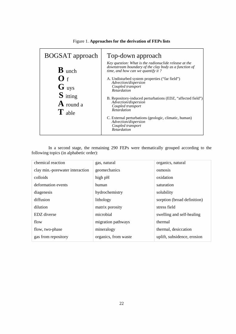
In a first stage, FEPs were collected on the basis of several national FEPs lists (Ondraf/Niras& SCK•CEN: Marivoet 1994, Bronders et al. 1994; Enresa: Enresa 1998a,b; Nagra: Gribi et al., 1998,Sumerling 1998), and by personal contributions of a number of experts. This approach to datacollection (“Take whatever is available and compile in useful format”) is inherently unstructured andtherefore called the “BOGSAT” (Bunch Of Guys Sitting Around a Table) approach (see Figure 1).While the resulting FEPs list is clearly linked to existing data, it depends, to some degree, on thematurity of the projects, on the preferences and biases of the underlying documents and opinions andso does not provide a way to check completeness. The FEPs list derived by this approach contained526 FEPs. At this stage, the list had no hierarchical structure or logical order and contained numerousredundancies, often explicit repetitions. A first FEPs screening was undertaken, applying the followingexclusion criteria:
• FEPs beyond the scope of FEPCAT as defined in Section I, Chapter 1.2 (e.g.retrievability, human activities);
• FEPs beyond timeframe of FEPCAT (order of 1 Ma);
• FEPs too general or too detailed and/or already covered by other FEPs (repetitions andevident redundancies);
• FEPs not specific to argillaceous media (e.g. meteorite impact);
• FEPs related exclusively to underground repository elements (e.g. waste, engineeredbarrier system);
• FEPs irrelevant for current repository designs (e.g. co-disposal with other hazardouswastes);
• FEPs of secondary priority (according to the judgement of the Expert Group; e.g. effectsof radiation on geosphere materials).
This first stage of screening resulted in a reduction of the number of FEPs to 290.
22
Figure 1. Approaches for the derivation of FEPs lists
Top-down approachKey question: What is the radionuclide release at thedownstream boundary of the clay body as a function oftime, and how can we quantify it ?
A. Undisturbed system properties (“far field”)Advection/dispersion
Coupled transport Retardation
B. Repository-induced perturbations (EDZ, “affected field”)Advection/dispersion
Coupled transport Retardation
C. External perturbations (geologic, climatic, human)Advection/dispersion
Coupled transport Retardation
B unch
O f
G uys
S itting
A round a
T able
BOGSAT approach
In a second stage, the remaining 290 FEPs were thematically grouped according to thefollowing topics (in alphabetic order):
chemical reaction gas, natural organics, natural
clay min.-porewater interaction geomechanics osmosis
colloids high pH oxidation
deformation events human saturation
diagenesis hydrochemistry solubility
diffusion lithology sorption (broad definition)
dilution matrix porosity stress field
EDZ diverse microbial swelling and self-healing
flow migration pathways thermal
flow, two-phase mineralogy thermal, desiccation
gas from repository organics, from waste uplift, subsidence, erosion
23
The list of topics above has been compiled on the basis of the existing FEPs list, i.e. it is notan independent check of completeness based on a structured approach. A second FEPs screening stagewas so performed according to the following criteria:
• Further elimination of redundancies and partial overlaps among FEPs.
• Achievement of a consistent degree of detail, i.e. elimination of very detailed FEPs. Forexample, a FEP “Fracture aperture changes in consequence of interaction betweenhyperalkaline water and clay minerals” would be eliminated because it is covered by“Hyperalkaline plume”.
The reduction of the number of FEPs from this screening was substantial, ending up with93 FEPs.
3.2 Top-down approach
While the size of the FEPs list was now manageable, it had no obvious hierarchy and noclear link to transport modelling or PA. Thus it is not straight-forward how its completeness can bechecked, and how it can be made useful for performance assessment issues. At this stage, it wasnecessary to incorporate the modelling perspective explicitly into the FEPs selection methodology.
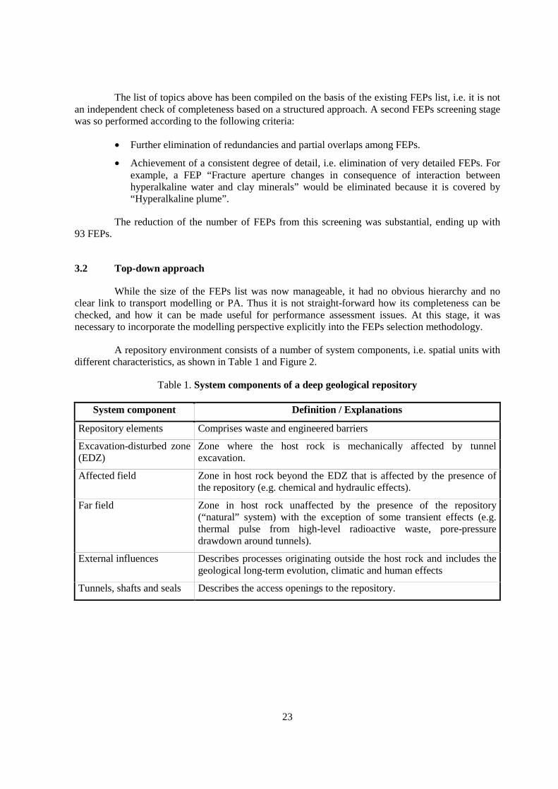
A repository environment consists of a number of system components, i.e. spatial units withdifferent characteristics, as shown in Table 1 and Figure 2.
Table 1. System components of a deep geological repository
System component Definition / Explanations
Repository elements Comprises waste and engineered barriers
Excavation-disturbed zone(EDZ)
Zone where the host rock is mechanically affected by tunnelexcavation.
Affected field Zone in host rock beyond the EDZ that is affected by the presence ofthe repository (e.g. chemical and hydraulic effects).
Far field Zone in host rock unaffected by the presence of the repository(“natural” system) with the exception of some transient effects (e.g.thermal pulse from high-level radioactive waste, pore-pressuredrawdown around tunnels).
External influences Describes processes originating outside the host rock and includes thegeological long-term evolution, climatic and human effects
Tunnels, shafts and seals Describes the access openings to the repository.
24
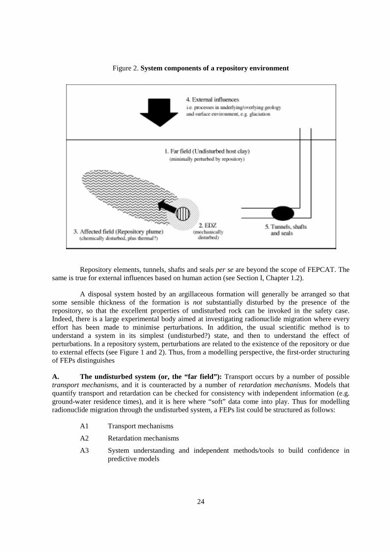
Figure 2. System components of a repository environment
Repository elements, tunnels, shafts and seals per se are beyond the scope of FEPCAT. Thesame is true for external influences based on human action (see Section I, Chapter 1.2).
A disposal system hosted by an argillaceous formation will generally be arranged so thatsome sensible thickness of the formation is not substantially disturbed by the presence of therepository, so that the excellent properties of undisturbed rock can be invoked in the safety case.Indeed, there is a large experimental body aimed at investigating radionuclide migration where everyeffort has been made to minimise perturbations. In addition, the usual scientific method is tounderstand a system in its simplest (undisturbed?) state, and then to understand the effect ofperturbations. In a repository system, perturbations are related to the existence of the repository or dueto external effects (see Figure 1 and 2). Thus, from a modelling perspective, the first-order structuringof FEPs distinguishes
A. The undisturbed system (or, the “far field”): Transport occurs by a number of possibletransport mechanisms, and it is counteracted by a number of retardation mechanisms. Models thatquantify transport and retardation can be checked for consistency with independent information (e.g.ground-water residence times), and it is here where “soft” data come into play. Thus for modellingradionuclide migration through the undisturbed system, a FEPs list could be structured as follows:
A1 Transport mechanisms
A2 Retardation mechanisms
A3 System understanding and independent methods/tools to build confidence inpredictive models

25
B. Repository-induced perturbations (including the excavation-disturbed zone (EDZ) and the“affected field”): These perturbations can be subdivided according to the different driving forces of theperturbations:
B1 Chemical perturbations
B2 Thermal perturbations
B3 Geomechanical perturbations
B4 Hydraulic perturbations
B5 Perturbations from coupled processes
B6 Perturbations from waste-derived gas
B7 Microbiological perturbations
C. External perturbations (geological long-term evolution in a broad sense): It is not straight-forward to include external effects on the argillaceous formation into a top-down approach. Long-termeffects can affect both transport and retardation mechanisms, with numerous and complexinterdependencies. Thus many of the external effects are not directly integrated in transport models,and their effects are studied by separate sub-models or in more qualitative terms. Structuring theexternal effects was done according to the possible groups of phenomena:
C1 Diagenesis
C2 Deformation events
C3 Erosion and burial.
3.3 The structured FEPs list
The top-down approach discussed in the last chapter resulted in a structured FEPs frameworkwhich was derived independently, i.e. without the use of pre-existing FEPs databases from theliterature. In the next step, the 93 FEPs from the BOGSAT approach were screened through thisapproach, with the following results:
• The integration was successful in that all 93 FEPs from the BOGSAT list could easily beallocated to a logical position in the structured list. This indicates that the suggested wayof structuring is practicable.
• In the integration procedure, FEPs from the BOGSAT list were allocated to differenthierarchical levels – e.g. “diagenesis” would be a higher hierarchy, whereas “Evolutionof pore fluid” is one of many effects of diagenesis and so is placed at lower hierarchicallevels. The development of structured FEPs lists more clearly shows the interrelations ofFEPs than flat lists. Moreover, in a structured list it is possible to cut off the degree ofdetail to which FEPs should be explored as a function of resources or state of knowledgein a particular field. For example, a FEP entitled “Coupled processes due to repository-induced perturbations” can be split up into sets of more detailed FEPs that describe theindividual couplings, e.g. thermo-mechanical, thermo-chemical, etc.
26
• A limited number of new FEPs emerged from the structured FEPs list that has not beenrepresented in the FEPs list derived from the BOGSAT approach. This indicates that,with some exceptions, the latter information is largely comprehensive.
The resulting structured FEPs list contained 74 unique entries and was used as thebasis for the questionnaires that were distributed to all participating organisations.
During the compilation of the answers to the questionnaires by the Expert Group, furthersimplifications became necessary:
• The FEP “Dilution” turned out not to have any characteristics specific to argillaceousformations and was deleted.
• Substantial answers for a number of FEPs were very limited (no answers came in at allfor some FEPs). This was due to a too high degree of detail and/or the limited PArelevance of these FEPs according to the judgement of the national organisations.However, the lack of information in itself was not a criterion for removing FEPs. SuchFEPs remained in the list but were merged with others, which resulted in a reduction to59 FEPs. FEPs groups where the number of answers was limited include:
B1 Chemical perturbations
B5 Perturbations from coupled processes
B6 Perturbations from waste-derived gas
B7 Microbiological perturbations.
C2 Deformation events
C3 Erosion and burial.
Thus major changes were performed in section C of the FEPs list (long-term evolution),some changes in section B (repository-induced perturbations), while section A (undisturbed system)remained almost unchanged.
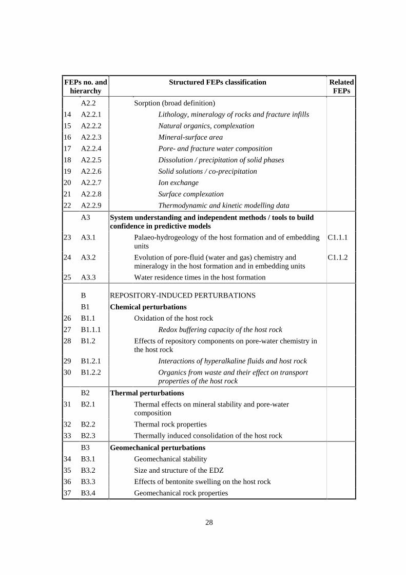
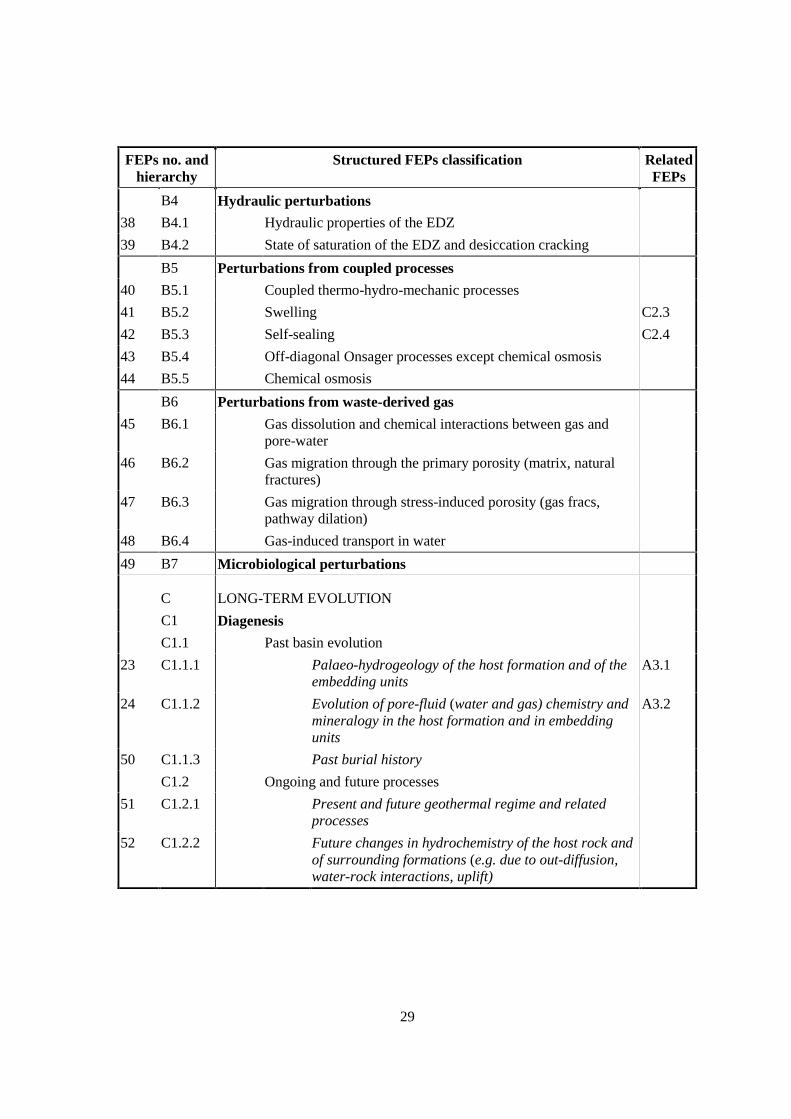
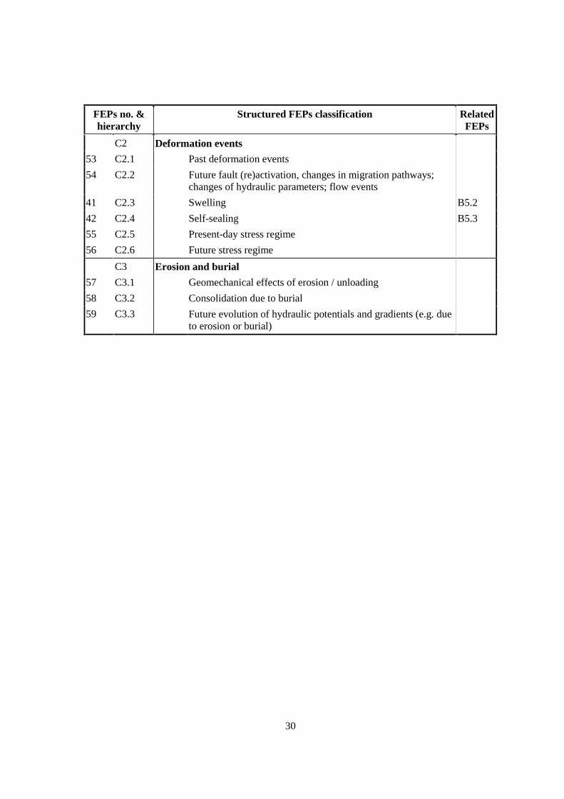
The final version of the structured FEPs list with 59 entries is presented in Table 2. Itcontains some features that need expanding further:
• The first column represents the running number of each FEP. This number is the basisfor the structuring of Section II of this report.
• The second column represents the hierarchical number of each FEP.
• Some of the higher-hierarchy FEPs are fully covered by FEPs in lower hierarchies, i.e.they are general titles to a group of FEPs that need not to be considered (e.g. “Sorption”).Therefore, such FEPs do not have a running number.
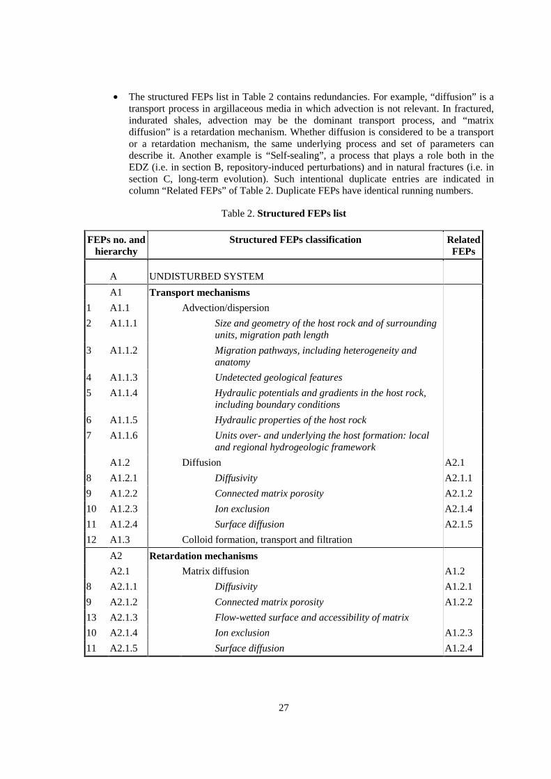
27
• The structured FEPs list in Table 2 contains redundancies. For example, “diffusion” is atransport process in argillaceous media in which advection is not relevant. In fractured,indurated shales, advection may be the dominant transport process, and “matrixdiffusion” is a retardation mechanism. Whether diffusion is considered to be a transportor a retardation mechanism, the same underlying process and set of parameters candescribe it. Another example is “Self-sealing”, a process that plays a role both in theEDZ (i.e. in section B, repository-induced perturbations) and in natural fractures (i.e. insection C, long-term evolution). Such intentional duplicate entries are indicated incolumn “Related FEPs” of Table 2. Duplicate FEPs have identical running numbers.
Table 2. Structured FEPs list
FEPs no. andhierarchy
Structured FEPs classification RelatedFEPs
A UNDISTURBED SYSTEM
A1 Transport mechanisms
1 A1.1 Advection/dispersion
2 A1.1.1 Size and geometry of the host rock and of surroundingunits, migration path length
3 A1.1.2 Migration pathways, including heterogeneity andanatomy
4 A1.1.3 Undetected geological features
5 A1.1.4 Hydraulic potentials and gradients in the host rock,including boundary conditions
6 A1.1.5 Hydraulic properties of the host rock
7 A1.1.6 Units over- and underlying the host formation: localand regional hydrogeologic framework
A1.2 Diffusion A2.1
8 A1.2.1 Diffusivity A2.1.1
9 A1.2.2 Connected matrix porosity A2.1.2
10 A1.2.3 Ion exclusion A2.1.4
11 A1.2.4 Surface diffusion A2.1.5
12 A1.3 Colloid formation, transport and filtration
A2 Retardation mechanisms
A2.1 Matrix diffusion A1.2
8 A2.1.1 Diffusivity A1.2.1
9 A2.1.2 Connected matrix porosity A1.2.2
13 A2.1.3 Flow-wetted surface and accessibility of matrix
10 A2.1.4 Ion exclusion A1.2.3
11 A2.1.5 Surface diffusion A1.2.4
28
FEPs no. andhierarchy
Structured FEPs classification RelatedFEPs
A2.2 Sorption (broad definition)
14 A2.2.1 Lithology, mineralogy of rocks and fracture infills
15 A2.2.2 Natural organics, complexation
16 A2.2.3 Mineral-surface area
17 A2.2.4 Pore- and fracture water composition
18 A2.2.5 Dissolution / precipitation of solid phases
19 A2.2.6 Solid solutions / co-precipitation
20 A2.2.7 Ion exchange
21 A2.2.8 Surface complexation
22 A2.2.9 Thermodynamic and kinetic modelling data
A3 System understanding and independent methods / tools to buildconfidence in predictive models
23 A3.1 Palaeo-hydrogeology of the host formation and of embeddingunits
C1.1.1
24 A3.2 Evolution of pore-fluid (water and gas) chemistry andmineralogy in the host formation and in embedding units
C1.1.2
25 A3.3 Water residence times in the host formation
B REPOSITORY-INDUCED PERTURBATIONS
B1 Chemical perturbations
26 B1.1 Oxidation of the host rock
27 B1.1.1 Redox buffering capacity of the host rock
28 B1.2 Effects of repository components on pore-water chemistry inthe host rock
29 B1.2.1 Interactions of hyperalkaline fluids and host rock
30 B1.2.2 Organics from waste and their effect on transportproperties of the host rock
B2 Thermal perturbations
31 B2.1 Thermal effects on mineral stability and pore-watercomposition
32 B2.2 Thermal rock properties
33 B2.3 Thermally induced consolidation of the host rock
B3 Geomechanical perturbations
34 B3.1 Geomechanical stability
35 B3.2 Size and structure of the EDZ
36 B3.3 Effects of bentonite swelling on the host rock
37 B3.4 Geomechanical rock properties
29
FEPs no. andhierarchy
Structured FEPs classification RelatedFEPs
B4 Hydraulic perturbations
38 B4.1 Hydraulic properties of the EDZ
39 B4.2 State of saturation of the EDZ and desiccation cracking
B5 Perturbations from coupled processes
40 B5.1 Coupled thermo-hydro-mechanic processes
41 B5.2 Swelling C2.3
42 B5.3 Self-sealing C2.4
43 B5.4 Off-diagonal Onsager processes except chemical osmosis
44 B5.5 Chemical osmosis
B6 Perturbations from waste-derived gas
45 B6.1 Gas dissolution and chemical interactions between gas andpore-water
46 B6.2 Gas migration through the primary porosity (matrix, naturalfractures)
47 B6.3 Gas migration through stress-induced porosity (gas fracs,pathway dilation)
48 B6.4 Gas-induced transport in water
49 B7 Microbiological perturbations
C LONG-TERM EVOLUTION
C1 Diagenesis
C1.1 Past basin evolution
23 C1.1.1 Palaeo-hydrogeology of the host formation and of theembedding units
A3.1
24 C1.1.2 Evolution of pore-fluid (water and gas) chemistry andmineralogy in the host formation and in embeddingunits
A3.2
50 C1.1.3 Past burial history
C1.2 Ongoing and future processes
51 C1.2.1 Present and future geothermal regime and relatedprocesses
52 C1.2.2 Future changes in hydrochemistry of the host rock andof surrounding formations (e.g. due to out-diffusion,water-rock interactions, uplift)
30
FEPs no. &hierarchy
Structured FEPs classification RelatedFEPs
C2 Deformation events
53 C2.1 Past deformation events
54 C2.2 Future fault (re)activation, changes in migration pathways;changes of hydraulic parameters; flow events
41 C2.3 Swelling B5.2
42 C2.4 Self-sealing B5.3
55 C2.5 Present-day stress regime
56 C2.6 Future stress regime
C3 Erosion and burial
57 C3.1 Geomechanical effects of erosion / unloading
58 C3.2 Consolidation due to burial
59 C3.3 Future evolution of hydraulic potentials and gradients (e.g. dueto erosion or burial)
31
4. QUESTIONNAIRE STRUCTURE
A dedicated database and an electronic questionnaire form were developed in FileMaker(version 3.0) and sent out to all participating organisations and external experts with the followingstructure:
Q1 FEP nameQ2 FEP definitionQ3 FEP classificationQ4 Occurrence of FEP in different argillaceous mediaQ5 Site-specific experimental information on FEP
• From in situ experiments• From a wider perspective of field information (e.g. natural analogues, palaeo-
hydrogeology)• From laboratory experiments• From numerical experiments• Scaling issues and tools for up- and downscaling
Q6 Level of understanding of FEP• From a scientific perspective• From a performance assessment perspective
Q7 Practical treatment of FEP in performance assessmentQ8 Coupling with other FEPsQ9 Availability of synthesis or state-of-the-art reviews
• Site-specific• More general but radwaste-related• Open literature
Q10 Planned work related to the FEP• Field• Laboratory• Modelling
Q11 Overall evaluation of FEPQ12 RemarksQ13 References

33
5. QUALITY AND NUMBER OF ANSWERS TO THE QUESTIONNAIRE
The national organisations participating in the FEPCAT project provided 179 answers toindividual questionnaire forms. Approximately half of these were to-the-point, technically completeand therefore highly useful for the compilation work by the Expert Group. On average, this equals 2.4answers, or 1.2 useful answers, per FEP. An additional 13 answers came from the Mont Terri Project.External Experts provided further 80 answers, of which 45 came from Mecsek/Puram (Hungary).
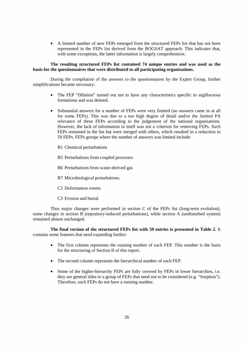
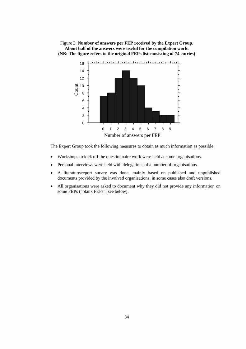
Figure 3 shows the distribution of the total number of answers per FEP. For the majority,2-5 answers were received. For 15 FEPs, only one answer, or no answer at all, was received. Thelimited number of answers received for each FEP results from the following facts:
• Some of the participating organisations currently do not carry out work on a specific sitein argillaceous rocks and therefore do not have complete data needed for filling in allquestionnaire forms. Some others have experience from underground researchlaboratories, where only a limited number of FEPs were studied. Out of the participatingorganisations, only a minority have a recent and complete safety case.
• Answering the questionnaires was technically demanding work, as both field-related andPA-relevant aspects of each FEP had to be brought together. Within many organisations,only a very limited number of experts exist with the necessary technical background, andthese are not fully available for projects such as FEPCAT. In retrospect, the question-naire size and structure appears too ambitious.
• Some organisations that were heavily involved in national programmes did not have themanpower resources to convey all available information.
34
Figure 3. Number of answers per FEP received by the Expert Group.About half of the answers were useful for the compilation work.
(NB: The figure refers to the original FEPs list consisting of 74 entries)
0
2
4
6
8
10
12
14
16
Cou
nt
0 1 2 3 4 5 6 7 8 9
Number of answers per FEP
The Expert Group took the following measures to obtain as much information as possible:
• Workshops to kick off the questionnaire work were held at some organisations.
• Personal interviews were held with delegations of a number of organisations.
• A literature/report survey was done, mainly based on published and unpublisheddocuments provided by the involved organisations, in some cases also draft versions.
• All organisations were asked to document why they did not provide any information onsome FEPs (“blank FEPs”; see below).
35
6. DOCUMENTATION OF UNANSWERED FEPS (“BLANK” FEPS)
During the project, it was felt important to better justify the rationale behind unansweredFEPs. Therefore, each participating organisation that left a substantial number of FEPs unansweredwas asked at a later stage about the reasons. The possible alternatives are given in Table 3, togetherwith the summary of the answers obtained. Alternatives 1, 2 and 3 (29 answers) mean that there is noneed to further pursue the FEPs. Alternatives 4 and 5 (129 answers) relate to FEPs that are regarded aspotentially important, with a poor level of available information, so further actions or thoughts shouldbe needed to improve their understanding. The relevance of alternatives 6 and 7 (52 answers) cannotbe judged at the present stage.
Table 3. Documentation of FEPs left blank in the questionnaires
Alternative Number of answers
1. FEP is of limited relevance or totally irrelevant in our safetystrategy/repository design.
26
2. FEP is potentially important, but we have no site-specific data. There issufficient evidence from other sites or from the scientific literature that canbe transferred to our site.
0 29
3. FEP is potentially important, but we have no site-specific data. The FEP isdifficult to investigate/quantify, so we cover it by conservative assumptionsand/or sensitivity analysis.
3
4. FEP is potentially important, but we have no site-specific data. We havenot investigated the FEP due to other priorities or limitations in ourprogramme.
121
129
5. We never thought of this FEP and so do not have any opinion. 8
6. We have information on this FEP but did not fill in the questionnaire due totime constraints.
2652
7. Other. 26
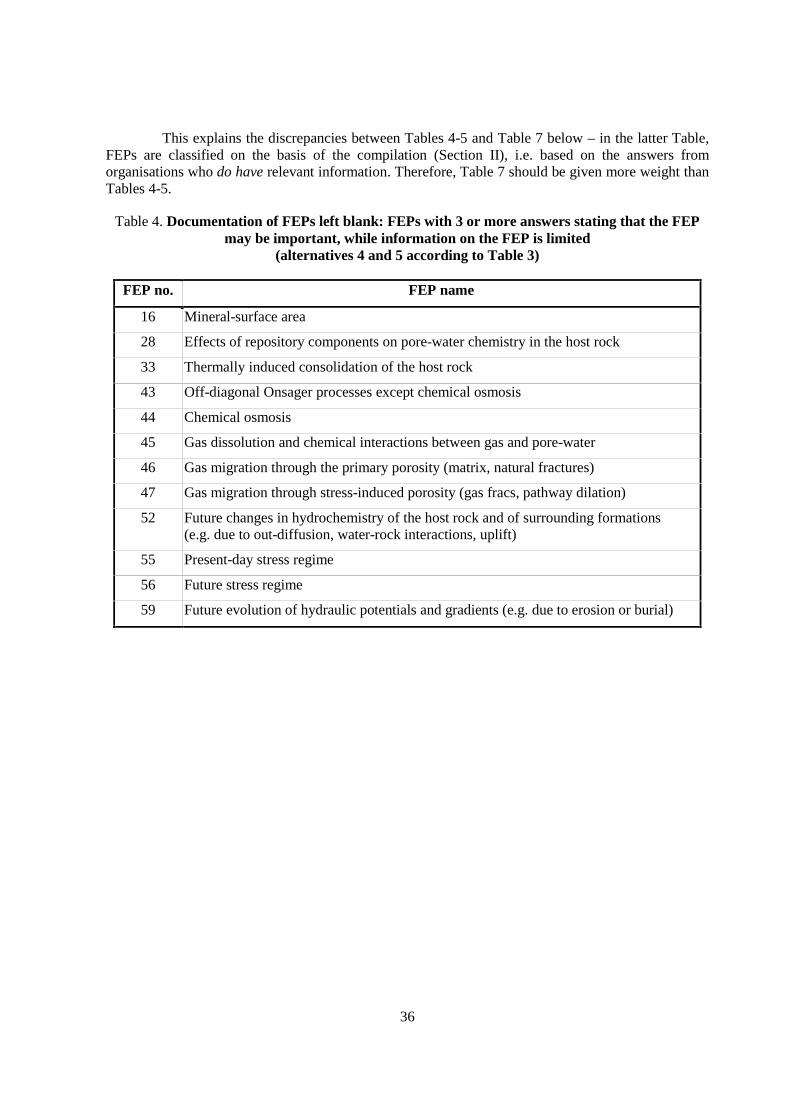
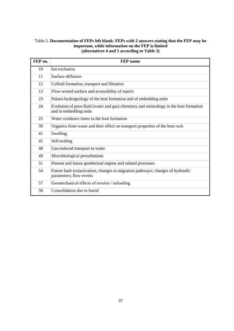
The alternatives 4 and 5 are obviously of the most interest, i.e. FEPs that are considered aspotentially relevant in PA with limited information. Table 4 indicates those FEPs that received 3 ormore category 4 and 5 responses. Table 5 indicates those FEPs that received 2 answers.
Table 4 and Table 5 must be interpreted carefully. When a participating organisation did nothave any data on a FEP, it was also unable to judge its potential relevance in PA. In such cases, itwould typically choose alternatives 4 and 5. At the same time, other organisations may haveinvestigated the FEP and concluded that it is not relevant.
36
This explains the discrepancies between Tables 4-5 and Table 7 below – in the latter Table,FEPs are classified on the basis of the compilation (Section II), i.e. based on the answers fromorganisations who do have relevant information. Therefore, Table 7 should be given more weight thanTables 4-5.
Table 4. Documentation of FEPs left blank: FEPs with 3 or more answers stating that the FEPmay be important, while information on the FEP is limited
(alternatives 4 and 5 according to Table 3)
FEP no. FEP name
16 Mineral-surface area
28 Effects of repository components on pore-water chemistry in the host rock
33 Thermally induced consolidation of the host rock
43 Off-diagonal Onsager processes except chemical osmosis
44 Chemical osmosis
45 Gas dissolution and chemical interactions between gas and pore-water
46 Gas migration through the primary porosity (matrix, natural fractures)
47 Gas migration through stress-induced porosity (gas fracs, pathway dilation)
52 Future changes in hydrochemistry of the host rock and of surrounding formations(e.g. due to out-diffusion, water-rock interactions, uplift)
55 Present-day stress regime
56 Future stress regime
59 Future evolution of hydraulic potentials and gradients (e.g. due to erosion or burial)
37
Table 5. Documentation of FEPs left blank: FEPs with 2 answers stating that the FEP may beimportant, while information on the FEP is limited
(alternatives 4 and 5 according to Table 3)
FEP no. FEP name
10 Ion exclusion
11 Surface diffusion
12 Colloid formation, transport and filtration
13 Flow-wetted surface and accessibility of matrix
23 Palaeo-hydrogeology of the host formation and of embedding units
24 Evolution of pore-fluid (water and gas) chemistry and mineralogy in the host formationand in embedding units
25 Water residence times in the host formation
30 Organics from waste and their effect on transport properties of the host rock
41 Swelling
42 Self-sealing
48 Gas-induced transport in water
49 Microbiological perturbations
51 Present and future geothermal regime and related processes
54 Future fault (re)activation, changes in migration pathways; changes of hydraulicparameters; flow events
57 Geomechanical effects of erosion / unloading
58 Consolidation due to burial

39
7. INSIGHTS BASED ON THE COMPILATION
A number of issues common to many programmes and thus of wider interest emerged fromthe compilation of answers (Section II of this report). Some of these issues could be further addressedin the future on an international level.
7.1 Scaling issues
For a substantial number of FEPs, process understanding and parameter values are availablebased on observations and measurements in deep boreholes, in underground research laboratories andin laboratory experiments. However, uncertainties are related to the upscaling in space and time:PA-relevant spatial scales (ca. 100 m) are 2-4 orders of magnitude larger that those typically addressedby experiments (cm – m). Upscaling in time is also important; typical PA time scales in the order ofca. 1 Ma are 6-9 orders of magnitude longer than experimental time scales (typically 1 day to 1 year).According to the analysis of the FEPs compilation (Section II), temporal and spatial upscaling isconsidered as a major issue for the following FEPs:
FEP 1 Advection/dispersion
FEP 3 Migration pathways, including heterogeneity and anatomy
FEP 4 Undetected geological features
FEP 6 Hydraulic properties of the host rock
FEP 8 Diffusivity
FEP 14 Lithology, mineralogy of rocks and fracture infills
FEP 29 Interactions of hyperalkaline fluids and host rock
FEP 35 Size and structure of the EDZ
FEP 36 Effects of bentonite swelling on the host rock
FEP 37 Geomechanical rock properties
FEP 38 Hydraulic properties of the EDZ
FEP 41 Swelling
FEP 42 Self-sealing
FEP 46 Gas migration through the primary porosity (matrix, natural fractures)
FEP 47 Gas migration through stress-induced porosity (gas fracs, pathway dilation)
FEP 48 Gas-induced transport in water
FEP 52 Future changes in hydrochemistry of the host rock and of surrounding formations (e.g. due toout-diffusion, water-rock interactions, uplift)
40
FEP 54 Future fault (re)activation, changes in migration pathways; changes of hydraulic parameters;flow events
FEP 59 Future evolution of hydraulic potentials and gradients (e.g. due to erosion or burial)
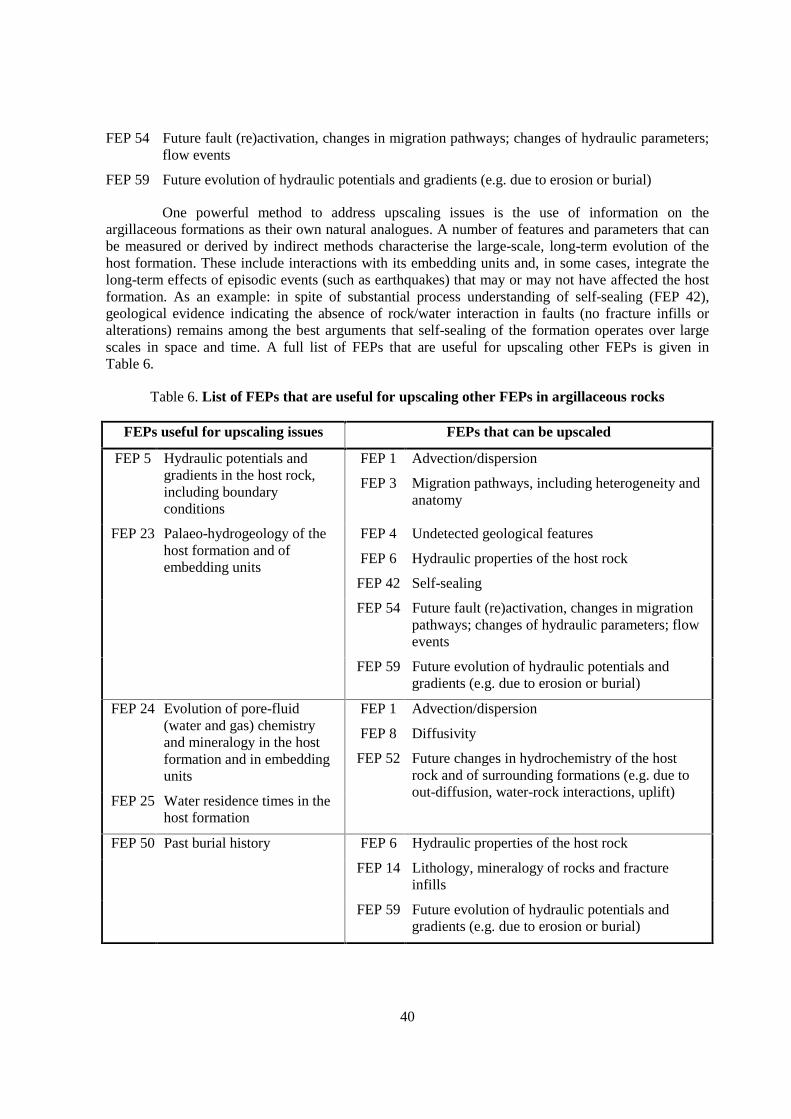
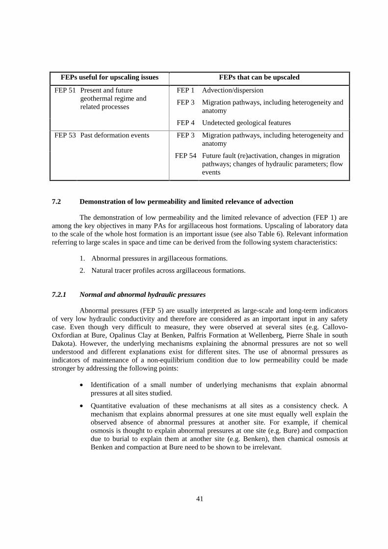
One powerful method to address upscaling issues is the use of information on theargillaceous formations as their own natural analogues. A number of features and parameters that canbe measured or derived by indirect methods characterise the large-scale, long-term evolution of thehost formation. These include interactions with its embedding units and, in some cases, integrate thelong-term effects of episodic events (such as earthquakes) that may or may not have affected the hostformation. As an example: in spite of substantial process understanding of self-sealing (FEP 42),geological evidence indicating the absence of rock/water interaction in faults (no fracture infills oralterations) remains among the best arguments that self-sealing of the formation operates over largescales in space and time. A full list of FEPs that are useful for upscaling other FEPs is given inTable 6.
Table 6. List of FEPs that are useful for upscaling other FEPs in argillaceous rocks
FEPs useful for upscaling issues FEPs that can be upscaled
FEP 5 Hydraulic potentials andgradients in the host rock,including boundaryconditions
FEP 1
FEP 3
Advection/dispersion
Migration pathways, including heterogeneity andanatomy
FEP 23 Palaeo-hydrogeology of thehost formation and ofembedding units
FEP 4
FEP 6
FEP 42
Undetected geological features
Hydraulic properties of the host rock
Self-sealing
FEP 54 Future fault (re)activation, changes in migrationpathways; changes of hydraulic parameters; flowevents
FEP 59 Future evolution of hydraulic potentials andgradients (e.g. due to erosion or burial)
FEP 24 Evolution of pore-fluid(water and gas) chemistryand mineralogy in the hostformation and in embeddingunits
FEP 25 Water residence times in thehost formation
FEP 1
FEP 8
FEP 52
Advection/dispersion
Diffusivity
Future changes in hydrochemistry of the hostrock and of surrounding formations (e.g. due toout-diffusion, water-rock interactions, uplift)
FEP 50 Past burial history FEP 6 Hydraulic properties of the host rock
FEP 14 Lithology, mineralogy of rocks and fractureinfills
FEP 59 Future evolution of hydraulic potentials andgradients (e.g. due to erosion or burial)
41
FEPs useful for upscaling issues FEPs that can be upscaled
FEP 51 Present and futuregeothermal regime andrelated processes
FEP 1
FEP 3
Advection/dispersion
Migration pathways, including heterogeneity andanatomy
FEP 4 Undetected geological features
FEP 53 Past deformation events FEP 3 Migration pathways, including heterogeneity andanatomy
FEP 54 Future fault (re)activation, changes in migrationpathways; changes of hydraulic parameters; flowevents
7.2 Demonstration of low permeability and limited relevance of advection
The demonstration of low permeability and the limited relevance of advection (FEP 1) areamong the key objectives in many PAs for argillaceous host formations. Upscaling of laboratory datato the scale of the whole host formation is an important issue (see also Table 6). Relevant informationreferring to large scales in space and time can be derived from the following system characteristics:
1. Abnormal pressures in argillaceous formations.
2. Natural tracer profiles across argillaceous formations.
7.2.1 Normal and abnormal hydraulic pressures
Abnormal pressures (FEP 5) are usually interpreted as large-scale and long-term indicatorsof very low hydraulic conductivity and therefore are considered as an important input in any safetycase. Even though very difficult to measure, they were observed at several sites (e.g. Callovo-Oxfordian at Bure, Opalinus Clay at Benken, Palfris Formation at Wellenberg, Pierre Shale in southDakota). However, the underlying mechanisms explaining the abnormal pressures are not so wellunderstood and different explanations exist for different sites. The use of abnormal pressures asindicators of maintenance of a non-equilibrium condition due to low permeability could be madestronger by addressing the following points:
• Identification of a small number of underlying mechanisms that explain abnormalpressures at all sites studied.
• Quantitative evaluation of these mechanisms at all sites as a consistency check. Amechanism that explains abnormal pressures at one site must equally well explain theobserved absence of abnormal pressures at another site. For example, if chemicalosmosis is thought to explain abnormal pressures at one site (e.g. Bure) and compactiondue to burial to explain them at another site (e.g. Benken), then chamical osmosis atBenken and compaction at Bure need to be shown to be irrelevant.
42
These issues are well suited to be addressed in the framework of a co-ordinated internationalstudy. Potential benefits of such an effort include:
• A better understanding of the underlying processes and mechanisms leading to abnormalpressures.
• An improved basis for site-specific argumentation with respect to the large-scale andlong-term hydrogeological evolution of the formation.
The first step in such a study would be the identification of gaps in the site-specificparameter sets and as far as reasonably possible the acquisition of missing data (e.g. pressure profilesor osmotic efficiencies).
7.2.2 Natural tracer profiles across argillaceous formations
A large number of tracers (e.g. 2HH2O, 18OH2O, Cl, 37Cl, Br, He, Ar) in the pore-water ofargillaceous formations have been investigated in profiles across several formations (FEPs 17 and 24;e.g. Couche silteuse at Marcoule/Gard, Callovo-Oxfordian at Bure, Toarcian-Domerian at Tournemire,Opalinus Clay at Mont Terri and at Benken). In many cases, curved distributions were observed andinterpreted as diffusion profiles (FEP 8). Provided the initial and boundary conditions for the diffusionprocess can be constrained on the basis of independent information, modelling of such profilespotentially leads to the following conclusions:
• Assessment of the relative importance of diffusion and advection as transport processes.A maximum advective flux can be derived, beyond which the shape of the modelledtracer profiles would no longer fit the observed distributions. Typically, such advectivefluxes are very small.
• Assessment of tracer-specific diffusion coefficients, referring to the spatial scale of theformation. These coefficients can be compared to those measured in the laboratory onsmall samples. Agreement among the two approaches would support the use oflaboratory-measured diffusion properties of tracers not measured in the field forformation-wide calculations. That is, such agreement would support upscaling oflaboratory results.
To date, different models and parameter sets were used at different sites, and a co-ordinatedeffort integrating information would improve the confidence in such models. The main issues couldinclude:
• As in the case of hydraulic overpressures discussed above, the same model should beable to explain the existence of bell-shaped profiles for some tracers and the absence ofsuch profiles for other tracers at a given site.
• Application of the same model to different sites should lead to consistent results (eventhough different parameter sets, e.g. diffusion coefficients and initial and boundaryconditions may be needed). Again, the models should explain both the presence ofcurved diffusion profiles at one site and profiles without a spatial variation of tracerconcentration (or isotopic ratio) at another site.
• There should be consistency in diffusion properties from site to site, taking into accountdifferences in site characteristics such as pore-fluid salinity, formation mineralogy,porosity, compaction, etc.

43
A co-ordinated study aimed at the interpretation of tracer profiles would require comparabledatabases at all sites. Some data may be missing at present and should be acquired in a first step (e.g.complete tracer profiles, characterisation of initial and boundary conditions, laboratory-deriveddiffusion coefficients).
7.3 Geochemical stability
While many argillaceous formations have demonstrably very low hydraulic conductivities,which result in very small advective fluxes, diffusive fluxes may be more substantial over relativelyshort geological time scales. As an example, Cl contents of pore-waters in argillaceous units of theBenken borehole (Opalinus Clay and underlying Liassic) can be shown to have decreased by a factorof ca. 3 within 1-2 Ma close to the contact with the underlying aquifer. Exchange processes betweenpore-waters in argillaceous formations and embedding aquifers are relevant topics both for the futureevolution of hydrochemistry (FEP 52) and the understanding of present-day pore-water compositions(FEP 17). Modelling of such exchange processes could contribute to our current understanding ofcontrols of pore-water chemistry, buffering capacity (FEPs 17, 27) and thus the geochemical stabilityof the host formations.
Pore-waters in argillaceous rocks are typically in chemical equilibrium with the mineralspresent in the formation. The geochemical stability of the formation and its pore-water can be alteredby changes in such boundary conditions as pressure, temperature and the pore-water chemistry ofadjacent formations. Changes in boundary conditions may result from regional tectonic or erosionalchanges or other processes such as salt-water intrusion in near-coastal sites. These will be reflected bychanges in the pore-water chemistry (and possibly the mineralogical properties) of a formation. Therates of change of these conditions for a site can often be evaluated from the geologic history of theregion and (or) from modelling profiles of chemical tracers, as described above. The immediate pastrate of change in formation chemistry may be applicable to the immediate future as well and so beuseful in developing a base-case scenario for site evolution for PA.
An added contribution to the geochemical stability of argillaceous rocks is that they arechemically rock-dominated. That is, the majority of the chemical species dissolved in pore-water arebuffered by minerals. The combination of fine grain size and extended pore-water residence timestypical of argillaceous rocks assures that changes to pore-water chemistry that might be brought aboutby repository construction or operation will be strongly buffered by rock-water reactions. Forexample, this aspect of the Opalinus Clay at Mont Terri is described in FEP 27 with particularrelevance to its redox buffer capacity.
7.4 Understanding diffusion
Diffusion is an important transport process in all types of argillaceous rocks and must beincluded in any PA involving such materials. In unfractured systems, diffusion is likely to be thedominant transport mechanism. In rocks where advective flow and transport may occur in fractures,diffusion from fracture to matrix fluid is an important retardation mechanism.
There is substantial evidence that Fick’s laws of diffusion also apply to argillaceous systems,and so in most PAs, these laws are used to describe diffusion of solutes. The empirical description ofdiffusion by means of Fick’s laws is currently considered to be state-of-the-art and sufficient for PApurposes.

44
Efforts are being made to develop mechanistic explanations for differences betweenpredictions made using classical diffusion theory and observations of transport in materials withcharged surfaces, large specific surface areas and very small pores. Many of these approaches are notsufficiently advanced and robust to be used in PAs. The following model approaches can be envisagedto quantify the total diffusive flux:
(a) A partitioned porosity approach in which it is assumed that electrostatic forces limit themovement of ions within the "ion-accessible" part of the total porosity. This approachinvokes a diffusion-accessible porosity for each ion, depending on valence and hydrated ionsize. Measurement of effective diffusivity is made using non-sorbing tracers, and thediffusive flux of sorbing tracers is calculated using distribution coefficients from batchsorption tests or from expert elicitation. This route has been contested by Oscarson (1994).The difficulty lies in determining the relevance of parameters measured in batch sorptiontests to retardation measured in laboratory or field diffusion tests.
(b) Complex calculations of ion transport in the electrolyte between narrowly-spaced chargedmineral surfaces, using an analytical model based on double-layer theory, or by using MonteCarlo simulation (and assumed pair-potentials). These are process models that are notsuitable for use in PA.
(c) A parallel pathway approach in which a simple subdivision of the medium is proposed. Thisapproach is pursued in Finnish studies to describe transport in compacted bentonite (e.g.Lehikoinen 1999). It postulates a subdivision into surface pathways and pore channels withan arbitrary boundary between the near-surface region, where “surface diffusion” is postu-lated, and the pores. In reality the activation energy for diffusion probably varies with dis-tance from surface, approaching the activation energy for bulk liquid viscosity at some dis-tance. In the Finnish approach, the postulated numerical relationships assume that the cross-sectional area for surface diffusion is the same as the cross-sectional area of the mineral sol-ids. The surface diffusion coefficient is therefore a phenomenological constant with no fun-damental significance.
(d) The average flux approach, based on direct laboratory measurements (diffusion tests) whichincorporate sorption. This is the simplest and most useful approach to PA, but it is verydemanding in terms of experimental effort. Even for moderately sorbing solutes, thisapproach leads to difficulties in the interpretation of the experimental results because onlysmall diffusion depths are possible within laboratory time scales. On the other hand, there isno need to worry about surface diffusion, since all possible mechanisms are incorporated inthe measurements.
(e) For formations with suitable physical properties (e.g. high enough hydraulic conductivitiesand sufficient plasticity), diffusion coefficients and diffusion porosities can be found from aseries of laboratory pulse injection experiments (Put, 1985, Put et al., 1991, Aertsenset al, 2003).
(f) The electromigration approach uses an electrical field to force ions to move towards theelectrode of opposite charge. From these experiments the apparent diffusion coefficient isobtained. Compared to the classical methods (through diffusion, percolation), this methoddecreases spectacularly the experimental time which is especially interesting for the study ofstrongly sorbed species (Maes et al., 1998, 1999, 2001, 2002). Because transport phenomenaother than just diffusion (such as electro osmosis) may also act in such experiments, it maybe necessary to "validate" the technique with the results of classical diffusion experimentswith samples of the same type of rock.
45
Approaches to constrain diffusion properties based on the measurement of electricalconductivity were also developed (e.g., Conca & Wright, 1990, 1991, Conca et al., 1993). Suchapproaches were mostly used for unsaturated rocks, and no experience is available for saturatedargillaceous rocks.
A recent report by Bradbury & Baeyens (2002) shows good agreement between thediffusivities obtained from diffusion tests (approach d) and diffusivities derived from distributioncoefficients measured in batch sorption tests (approach a) for Cs(I), Ni(II), Sm(III), Am(III), Zr(IV)and Np(V). It was important in this comparison to properly adapt the distribution coefficients to therelevant pore-water composition. This report does not entirely solve the problems of compatibilitybetween approaches (a) and (d) because it reports that for other elements less favourable agreementwas observed. FEPs 8 through 11, the A1.2 (Diffusion) and A2.1 (Retardation mechanism) series,address parameters and processes that should be considered when evaluating various approaches toestablishing parameters used to calculate diffusive fluxes for PA.
7.5 Understanding sorption
Sorption in the broad sense refers to the partitioning of a substance between solid phase(s)and solution. Due to sorption, the transport rate of the bulk substance is retarded relative to the rate ofmovement of the solution. There is a large amount of empirical evidence that sorption on mineralsurfaces occurs, among others on clay minerals. Sorption is commonly included in PA using thedistribution coefficient (Kd) parameter. Kd values vary by substance, substrate and solution properties.They can be derived from laboratory measurements using material from the formation of interest, orindividual minerals typical of those in the host rock. Alternatively, they can be calculated from De andDa values of the formation (FEP 8). For simple systems, approaches exist or are being developed tomodel sorption based on mechanistic principles, although this is not (yet) feasible for more complexsystems.
To extend laboratory data and justify their application in differing PA environments,Altmann & Bruno (2001) describe a process-based interpretation of sorption, the ThermodynamicSorption Model (TSM). This model treats sorption in terms of two component processes: ion exchange(FEP 20) and surface complexation (FEP 21). An important purpose of such a process-basedinterpretation is to build confidence in the use of simplified, empirical parameters, such as Kd values todescribe sorption processes.
Because of its high clay-mineral content, the number of ion exchange sites in a typicalargillaceous rock far exceeds the number of surface complexation sites, although the latter tend tobond more strongly to solutes of interest in PA than do the former. Ion exchange reactions are wellunderstood and characterised insofar as they influence the major ion chemistry of pore-waters.Mechanistic modelling of reactions controlling the sorption of trace elements, whether treatedformally as ion exchange or surface complexation reactions, works sufficiently well for puresubstances such as metal oxides and hydroxides or clay minerals in simple solutions. The applicationof mechanistic models to complex systems, however is, still a difficult task.
46
Davis et al. (1998) examine two techniques for applying the surface complexation model topredict Kd values for natural systems with mineralogy and water chemistry of normal field complexity:
• In the first, termed Component Additivity (CA), the densities of sites corresponding to anumber of specific sorbents are determined. The stability constants and reactionsassociated with each specific sorbent are known from laboratory studies and the overallsorption is predicted as the sum of the sorption corresponding to each site.
• The second technique is called the Generalised Composite (GC) method. Here,laboratory sorption measurements on the bulk host rock are made by using artificialpore-waters with compositions spanning those expected in the environment to bemodelled. These results are simulated using the simplest surface complexation modelthat provides an acceptable fit to the laboratory data. Because the experimental databracket the environmental conditions, the simulation will be applicable to the fieldproblem.
Davis et al. (1998) compare the two methods for a system in which sorption occurs onmineral oxide and hydroxide coatings. The site densities of these coatings could not be characterisedprecisely enough for the CA method to yield results comparable to those of the GC method.
On the other hand, Bradbury & Baeyens (1997, 2003) employ a method analogous to the CAmethod using a series of conversion factors to generate Kd values for the Palfris Formation and forOpalinus Clay from the properties of its components. Their results are in generally good agreementwith results of the GC method, presumably because the sorption capacity of the formation is dueprincipally to ion exchange and surface sites of illite and mixed-layer smectite-illite, the quantities ofwhich can be determined with acceptable precision.
The ongoing NEA Sorption Project aims at maintaining consistency among different nationalprogrammes and to co-ordinate various modelling approaches. The objective of Phase II of this projectis to demonstrate the applicability of different thermodynamic modelling approaches to support theselection of sorption parameters for PA. First results of this work are documented in Payne et al.(2003) and Davis et al. (2003).
The difficulties associated with the upscaling of laboratory data are recognised and are beingaddressed by field studies in underground research laboratories, by studies of trace element transportfrom conventional waste disposal sites, such as that of Davis et al. (1998), and in laboratory andtheoretical studies in support of many national nuclear waste programmes to improve mechanisticunderstanding.
7.6 Time evolution and geometry of the EDZ, self-sealing
In geotechnical and mining engineering, the evolution and geometry of the “Plastic Zone” aspart of an EDZ is a key issue in the design of tunnels and other underground openings. Many theorieshave been developed, but the availability of appropriate data is still a major issue. In-depthinformation from various underground research laboratories constitutes a very valuable set of muchneeded new in situ data. Moreover, purpose-designed innovative tools were developed which enablean accurate delineation of the geometry, extent and evolution of the plastic zone. An example is theInterval Velocity Measuring Method in boreholes developed by Alheid and co-workers, which wasemployed e.g. in Tournemire and Mont Terri (Schuster et al., 1999). The investigations carried out inthe New Gallery of the underground research laboratory at Mont Terri revealed the extent and degree

47
of fracturing of the EDZ and the changes with time in a detail which, in the opinion of the ExpertGroup, is without precedent in underground construction.
The evolution of the EDZ after repository closure is affected by a number of processes, suchas resaturation, pressure build-up, swelling and disintegration/homogenisation on a nanometric scale.These processes contribute to self-sealing, i.e. the reduction of hydraulic conductivity of fractures withtime. Self-sealing is of key importance to PA and is often cited as an important factor favouring thechoice of argillaceous formations as host rocks for deep disposal. Self-sealing directly addresses thefunctionality of the argillaceous host rocks as a migration barrier. When the self-sealing processproceeds in reasonable time, fractures created by the construction of the repository will not persist aspreferential pathways for radionuclide migration, and thus the system becomes diffusion-dominated.
Self-sealing also occurs in natural fractures and faults penetrating argillaceous rocks.Substantial evidence exists that natural fractures are not hydraulically active and have not been activeover geological periods of time. In Swiss railway tunnels (>100 years old) in the Jura Mountains, nowater inflows were observed at an overburden >200 m, in spite of the presence of major faults.Evidence from other sites is consistent with this observation. This set of observations constitutes astrong geological argument for the self-sealing capabilities of argillaceous formations, addressing bothsealing of natural fractures as well as the EDZ around underground openings.
Self-sealing mechanisms have been widely observed in a variety of argillaceous rocks, andthe basic physico-chemical and hydro-mechanical processes leading to self-sealing are wellunderstood. In plastic clays, self-sealing is expected to be a rather quick process. In more induratedargillaceous rocks, self-sealing is expected to be slower. However, the currently available knowledgeis not yet sufficient to permit detailed predictions concerning the kinetics of the self-sealing process invarious types of argillaceous media.
In spite of the existing data and observations, understanding still needs to be improved. Onequestion is whether the observed self-sealing of natural fractures can be extrapolated to the sometimesgeometrically different fracture arrays in an EDZ. Wedge-shaped and composite fracture planes, forinstance, may develop in the roof of tunnels excavated in horizontally bedded argillaceous rocks. Forthis case geological analogues may be of limited value, as natural and EDZ fracture planes may bedifferent in shape. The resistance to closure of composite and wedge-shaped fracture planes,particularly in response to swelling pressures originating in the formation and/or in the backfill, shouldbe carefully investigated. Such questions can be addressed by experiments in underground researchlaboratories, such as the EC SELFRAC project. In this project, in situ experiments studying thekinetics of the self-sealing process have only recently been conducted at Mol and at Mont Terri. Itwould also be interesting to study self-sealing in more strongly indurated formations, such as in theToarcian-Domerian at Tournemire.
Besides the hydro-mechanical evolution of the EDZ, chemical reactions may occur in theEDZ during the operational phase of the repository. For example, EDZ fractures create pathways foroxygen. The most relevant chemical effect is the oxidation of pyrite, which occurs as an accessoryphase in all formations considered (except for the Boda Clay Formation). There is substantial evidencethat pyrite oxidation will not have detrimental effects on the geochemical and geomechanicalproperties of the EDZ. Evidence from laboratory experiments and from natural analogues (such astunnels penetrating argillaceous formations or surface-near decompaction fractures) indicates thatoxidation penetrates only a few cm into the rock matrix even if exposure to air occurs over decades.The acid produced due to pyrite oxidation will be consumed by a small degree of calcite dissolution,thus pH will be buffered by the carbonate system and will not drop substantially (all formationsconsidered contain calcite). As the EDZ self-seals, the access of oxygen to the rock gets blocked. Thus
48
the kinetics of the self-sealing process will influence the magnitude of oxidation and, by consequence,the geochemistry in the affected field of the repository.
7.7 Present-day stress regime
In most answers to the questionnaires, the present-day (geologic) stress regime is generallyacknowledged to be a relevant FEP (see Section II, Chapter 55). On the other hand, the questionnairesalso show that problems commonly exist in the experimental determination of the site-specific in situstress state in argillaceous rocks, and meaningful conclusions need to be based on a variety ofindividual measurements and observations. At Mont Terri, for instance, even a combined applicationof various standard stress-measuring techniques (overcoring; undercoring; borehole slotting; hydraulicfracturing) did not reveal a reasonably coherent picture of the local geologic stress regime. It was onlyafter the back-analysis of the deformational behaviour of the excavations of the underground rocklaboratory that a consistent picture emerged. Similarly, at other sites, additional evidence had to beconsidered to interpret in situ stress measurements with confidence. Such evidence may consist ofeither geologic stress indicators (e.g. stylolites; orientation of volcanic dykes, faults or joints) ortechnical stress indicators (e.g. borehole breakouts; spalling of tunnel walls; orientation of blast holefractures).
Obviously, argillaceous rocks constitute an “intermediate” material in which neither thestandard stress measuring techniques originally developed for hard rocks (e.g. the above-mentionedmethods) nor those developed for soft soils (e.g. total pressure cell inclusions) are easily applicable. Inargillaceous materials it is often difficult to provide well-shaped cylindrical boreholes (which arerequired e.g. in hydro-fracturing and overcoring). The borehole wall itself is commonly disturbed andfractured. The rock close to the borehole wall thus does not necessarily behave in a linear-elastic way,which is one of the pre-requisites for under- and overcoring as well as for borehole slotting stressmeasuring tests. Against the background of these conceptual and technical difficulties, it appearsmeaningful to review the usefulness of the various in situ stress measuring methods in argillaceousmaterials in a more systematic manner and to pursue a special programme for the adjustment and/orthe development of in situ stress measuring techniques, if required.
7.8 Conceptual micro-mechanical models
The number and application fields of conceptual micro-mechanical models as specified inthe answers to the questionnaires are quite remarkable, if not surprising. Examples of micro-mechanical modelling were mentioned in connection with FEPs 37 (Geomechanical rock properties)and 47 (Gas migration through stress-induced porosity). Other applications include the modelling ofcompaction (FEP 50) and self-sealing (FEP 42) processes.
Since the formulation of the “effective stress principle” (Terzaghi, 1925), it is generallyacknowledged that micro-mechanical models are keys for an in-depth mechanical understanding ofsoils and rocks and for the prediction of their thermo-hydro-mechanical response to forces in spaceand time. Comprehensive formulations of material behaviours by means of micro-mechanical modelsrequire the determination of a vast number of parameters as well as the consideration of numerousinteraction processes. In most standard applications, micro-mechanical modelling was and still isconsidered to be impractical. However, with the advent of powerful micro-mechanical numericalmodelling codes (e.g. PFC – Particle Flow Code of the Distinct Element Method) and driven by thesteadily increased computing power, the situation is rapidly changing. This, for instance, isdocumented in Konietzky (2003), where ample evidence is provided that, beyond geomechanics,
49
micro-mechanical modelling is successfully carried out in scientific fields and applications as diverseas process engineering, chemical industry, material science, agriculture and mechanical engineering.
The FEPs compilation indicates that micro-mechanical modelling became a realisticperspective for argillaceous rocks. Such modelling has the potential to adequately describe and predictgeomechanical phenomena which are often intractable in conventional generic-type mechanicalmodels. Examples of such phenomena are time-dependent deformation (“creep”), the development ofshear bands and the clustering of particles. Particularly with regard to the mechanisms which may leadto “secondary creep” in argillaceous rocks, it is, in the opinion of the Expert Group, desirable to carryout further systematic micro-mechanical modelling studies to enhance understanding of the relevantprocesses. When addressing PA-relevant time scales, upscaling in space and time (as discussed inSection I, Chapter 7.1) is needed for experiments carried out in laboratories or underground researchlaboratories. For example, the upscaling of creep requires some understanding of the underlyingphysico-chemical mechanisms and processes on a microscopic scale.

51
8. CLASSIFICATION OF FEPS ACCORDING TO STATE OF KNOWLEDGE ANDPOTENTIAL RELEVANCE FOR PERFORMANCE ASSESSMENT
The full FEPs compilation (Section II of this report) addresses, among other issues:
• the scientific and PA-related state of knowledge on each FEP; and
• the relevance of each FEP for PA (or, more broadly, for a safety case).
In Table 7, this information has been summarised and classified in a small number ofcategories. Even though this is a simplification of a highly complex situation, it may be used by eachnational organisation as a potential checklist to qualify its own progress in a disposal project.However, the table must not be mistaken as a universal rating for the following reasons:
• The relevance of a FEP for a disposal project depends on system-specific requirementsand boundary conditions (e.g. type of waste, disposal concept, type of engineeredbarriers). Some FEPs might be of importance in one concept but not an issue in another.
• Some FEPs that could be relevant for radionuclide transport can be neglected if it can beshown that disregarding them leads to an overestimation of calculated doses. Forexample, the low-permeability formations embedding the Opalinus Clay in the ZürcherWeinland were characterised to a less detailed degree than the host formation itself. Inthe radionuclide transport calculations, retention in these units was not considered in thebase case, which is a simplification leading to higher calculated doses.
• The degree of knowledge on a FEP varies among disposal projects at different stages ofmaturity (regional or generic feasibility study, site-specific work from the surface, site-specific underground research laboratory, etc.).
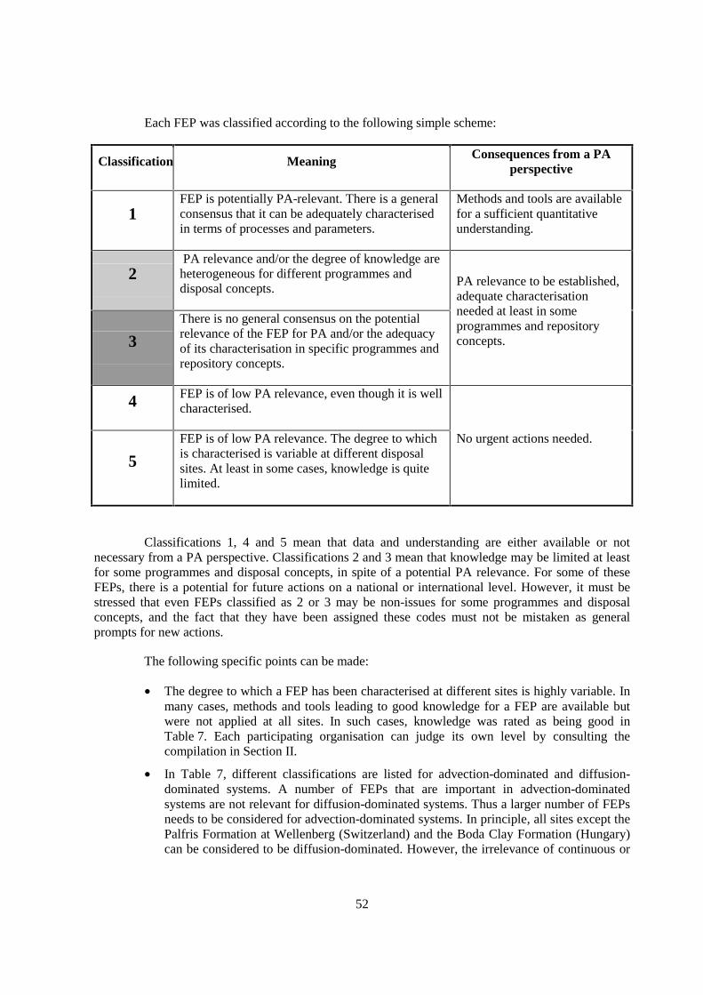
52
Each FEP was classified according to the following simple scheme:
Classification Meaning Consequences from a PAperspective
1FEP is potentially PA-relevant. There is a generalconsensus that it can be adequately characterisedin terms of processes and parameters.
Methods and tools are availablefor a sufficient quantitativeunderstanding.
2 PA relevance and/or the degree of knowledge areheterogeneous for different programmes anddisposal concepts.
3
There is no general consensus on the potentialrelevance of the FEP for PA and/or the adequacyof its characterisation in specific programmes andrepository concepts.
PA relevance to be established,adequate characterisationneeded at least in someprogrammes and repositoryconcepts.
4 FEP is of low PA relevance, even though it is wellcharacterised.
5
FEP is of low PA relevance. The degree to whichis characterised is variable at different disposalsites. At least in some cases, knowledge is quitelimited.
No urgent actions needed.
Classifications 1, 4 and 5 mean that data and understanding are either available or notnecessary from a PA perspective. Classifications 2 and 3 mean that knowledge may be limited at leastfor some programmes and disposal concepts, in spite of a potential PA relevance. For some of theseFEPs, there is a potential for future actions on a national or international level. However, it must bestressed that even FEPs classified as 2 or 3 may be non-issues for some programmes and disposalconcepts, and the fact that they have been assigned these codes must not be mistaken as generalprompts for new actions.
The following specific points can be made:
• The degree to which a FEP has been characterised at different sites is highly variable. Inmany cases, methods and tools leading to good knowledge for a FEP are available butwere not applied at all sites. In such cases, knowledge was rated as being good inTable 7. Each participating organisation can judge its own level by consulting thecompilation in Section II.
• In Table 7, different classifications are listed for advection-dominated and diffusion-dominated systems. A number of FEPs that are important in advection-dominatedsystems are not relevant for diffusion-dominated systems. Thus a larger number of FEPsneeds to be considered for advection-dominated systems. In principle, all sites except thePalfris Formation at Wellenberg (Switzerland) and the Boda Clay Formation (Hungary)can be considered to be diffusion-dominated. However, the irrelevance of continuous or
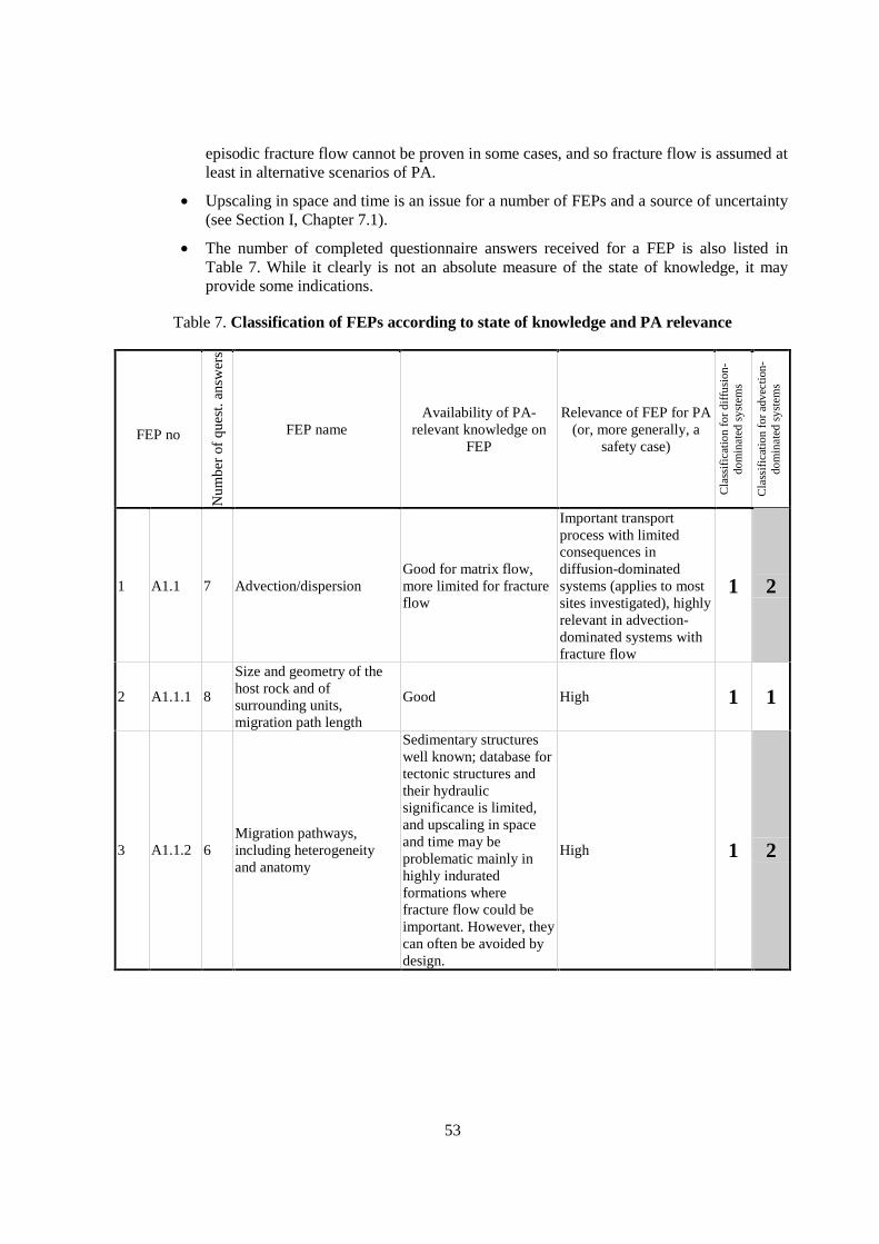
53
episodic fracture flow cannot be proven in some cases, and so fracture flow is assumed atleast in alternative scenarios of PA.
• Upscaling in space and time is an issue for a number of FEPs and a source of uncertainty(see Section I, Chapter 7.1).
• The number of completed questionnaire answers received for a FEP is also listed inTable 7. While it clearly is not an absolute measure of the state of knowledge, it mayprovide some indications.
Table 7. Classification of FEPs according to state of knowledge and PA relevance
FEP no
Num
ber
of q
uest
. ans
wer
s
FEP nameAvailability of PA-
relevant knowledge onFEP
Relevance of FEP for PA(or, more generally, a
safety case)
Cla
ssif
icat
ion
for
diff
usio
n-do
min
ated
sys
tem
s
Cla
ssif
icat
ion
for
adve
ctio
n-do
min
ated
sys
tem
s
1 A1.1 7 Advection/dispersionGood for matrix flow,more limited for fractureflow
Important transportprocess with limitedconsequences indiffusion-dominatedsystems (applies to mostsites investigated), highlyrelevant in advection-dominated systems withfracture flow
1 2
2 A1.1.1 8
Size and geometry of thehost rock and ofsurrounding units,migration path length
Good High 1 1
3 A1.1.2 6Migration pathways,including heterogeneityand anatomy
Sedimentary structureswell known; database fortectonic structures andtheir hydraulicsignificance is limited,and upscaling in spaceand time may beproblematic mainly inhighly induratedformations wherefracture flow could beimportant. However, theycan often be avoided bydesign.
High 1 2
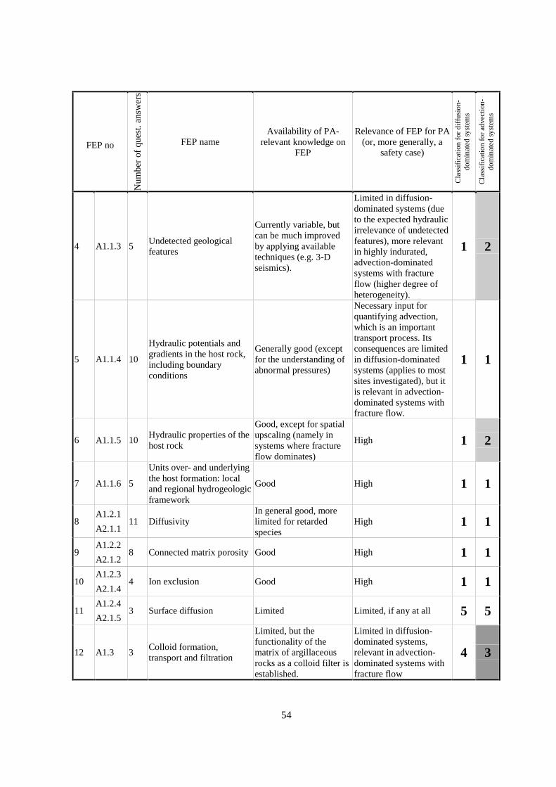
54
FEP noN
umbe
r of
que
st. a
nsw
ers
FEP nameAvailability of PA-
relevant knowledge onFEP
Relevance of FEP for PA(or, more generally, a
safety case)
Cla
ssif
icat
ion
for
diff
usio
n-do
min
ated
sys
tem
s
Cla
ssif
icat
ion
for
adve
ctio
n-do
min
ated
sys
tem
s
4 A1.1.3 5Undetected geologicalfeatures
Currently variable, butcan be much improvedby applying availabletechniques (e.g. 3-Dseismics).
Limited in diffusion-dominated systems (dueto the expected hydraulicirrelevance of undetectedfeatures), more relevantin highly indurated,advection-dominatedsystems with fractureflow (higher degree ofheterogeneity).
1 2
5 A1.1.4 10
Hydraulic potentials andgradients in the host rock,including boundaryconditions
Generally good (exceptfor the understanding ofabnormal pressures)
Necessary input forquantifying advection,which is an importanttransport process. Itsconsequences are limitedin diffusion-dominatedsystems (applies to mostsites investigated), but itis relevant in advection-dominated systems withfracture flow.
1 1
6 A1.1.5 10Hydraulic properties of thehost rock
Good, except for spatialupscaling (namely insystems where fractureflow dominates)
High 1 2
7 A1.1.6 5
Units over- and underlyingthe host formation: localand regional hydrogeologicframework
Good High 1 1
8A1.2.1
A2.1.111 Diffusivity
In general good, morelimited for retardedspecies
High 1 1
9A1.2.2
A2.1.28 Connected matrix porosity Good High 1 1
10A1.2.3
A2.1.44 Ion exclusion Good High 1 1
11A1.2.4
A2.1.53 Surface diffusion Limited Limited, if any at all 5 5
12 A1.3 3Colloid formation,transport and filtration
Limited, but thefunctionality of thematrix of argillaceousrocks as a colloid filter isestablished.
Limited in diffusion-dominated systems,relevant in advection-dominated systems withfracture flow
4 3

55
FEP noN
umbe
r of
que
st. a
nsw
ers
FEP nameAvailability of PA-
relevant knowledge onFEP
Relevance of FEP for PA(or, more generally, a
safety case)
Cla
ssif
icat
ion
for
diff
usio
n-do
min
ated
sys
tem
s
Cla
ssif
icat
ion
for
adve
ctio
n-do
min
ated
sys
tem
s
13 A2.1.3 2Flow-wetted surface andaccessibility of matrix
Fair
Irrelevant in diffusion-dominated systems, morerelevant in advection-dominated systems withfracture flow
4 2
14 A2.2.1 7Lithology, mineralogy ofrocks and fracture infills
Good High 1 1
15 A2.2.2 6Natural organics,complexation
Fair
Variable (depending onthe nature of the organicmatter involved and thenuclide inventory);complexation: high
2 2
16 A2.2.3 2 Mineral-surface area Good High 1 1
17 A2.2.4 6Pore- and fracture watercomposition
Good except for 1)modelling uncertaintyand 2) distinctionbetween fracture andmatrix water.
High 1 2
18 A2.2.5 3Dissolution/precipitation ofsolid phases
Major phases: good;phases limitingsolubilities ofradionuclides: limited.
High (solubility limits ofradionuclides) 2 2
19 A2.2.6 1Solid solutions/co-precipitation
Moderate; can bemodelled in principle.
Potentially high, often(conservatively)neglected
2 2
20 A2.2.7 4 Ion exchangeGood; can me modelledin principle but data arelimited.
High 1 1
21 A2.2.8 5 Surface complexationFair (empiric datasufficient, mechanisticunderstanding limited)
High 2 2
22 A2.2.9 5Thermodynamic andkinetic modelling data
Variable (depending onelement)
High 2 2
23A3.1
C1.1.14
Palaeo-hydrogeology ofthe host formation and ofembedding units
Good in principle eventhough not available infull at all sites
High 1 1
24A3.2
C1.1.25
Evolution of pore-fluid(water and gas) chemistryand mineralogy in the hostformation and inembedding units
Good in principle eventhough not available infull at all sites
High 1 1
25 A3.3 5Water residence times inthe host formation
Good in principle eventhough not available infull at all sites
High 1 1

56
FEP noN
umbe
r of
que
st. a
nsw
ers
FEP nameAvailability of PA-
relevant knowledge onFEP
Relevance of FEP for PA(or, more generally, a
safety case)
Cla
ssif
icat
ion
for
diff
usio
n-do
min
ated
sys
tem
s
Cla
ssif
icat
ion
for
adve
ctio
n-do
min
ated
sys
tem
s
26 B1.1 4 Oxidation of the host rock GoodVariable; depends onformation, repositorydesign and operation
1 1
27 B1.1.1 1Redox buffering capacityof the host rock
Good, but reaction ratesare difficult to measure
Variable (systemdependent) 2 2
28 B1.2 0Effects of repositorycomponents on pore-waterchemistry in the host rock
Limited (no questionnaireanswers received)
Effects are expected to bespatially limited indiffusion-dominatedsystems; otherwise notwell established.
2 3
29 B1.2.1 4Interactions ofhyperalkaline fluids andhost rock
Fair (but the issue iscomplex)
Effects are spatiallylimited at least indiffusion-dominatedsystems; potentiallyrelevant in advection-dominated systems.
1 2
30 B1.2.2 4Organics from waste andtheir effect on transportproperties of the host rock
Limited
Effects are spatiallylimited at least indiffusion-dominatedsystems; otherwise notwell known due to thescarcity of information.
2 3
31 B2.1 3Thermal effects on mineralstability and pore-watercomposition
Fair Limited 4 4
32 B2.2 7 Thermal rock properties Good High 1 1
33 B2.3 3Thermally inducedconsolidation of the hostrock
Limited Limited 5 5
34 B3.1 6 Geomechanical stability GoodLimited for PA butimportant for the safetyconcept
1 1
35 B3.2 6Size and structure of theEDZ
Fair High 2 2
36 B3.3 2Effects of bentoniteswelling on the host rock
Good, except for scarcityof experimental data andunderstanding ofclosure mechanisms offractures, mainly insystems with fractureflow
High 1 1
37 B3.4 6Geomechanical rockproperties
Variable (depending onsite/programme)
High (repository conceptand PA) 2 2
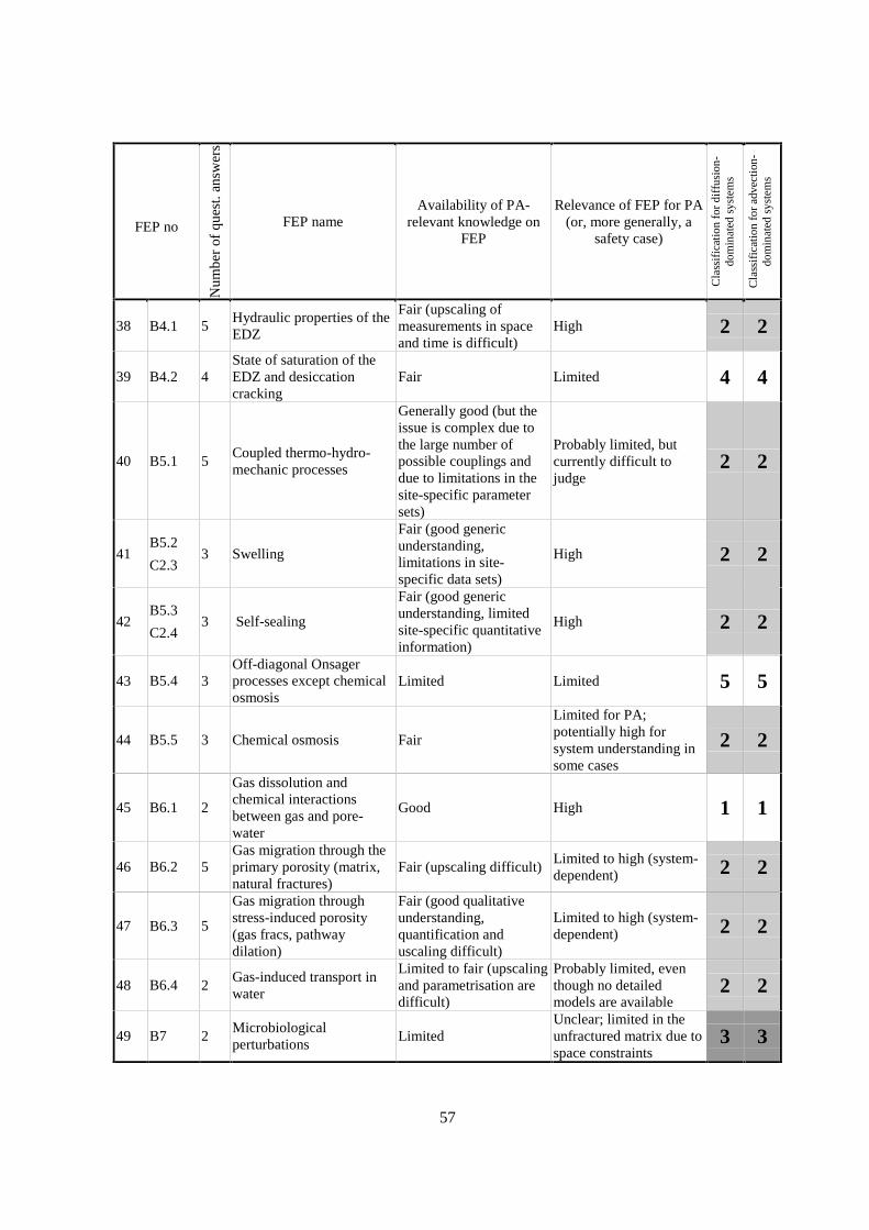
57
FEP noN
umbe
r of
que
st. a
nsw
ers
FEP nameAvailability of PA-
relevant knowledge onFEP
Relevance of FEP for PA(or, more generally, a
safety case)
Cla
ssif
icat
ion
for
diff
usio
n-do
min
ated
sys
tem
s
Cla
ssif
icat
ion
for
adve
ctio
n-do
min
ated
sys
tem
s
38 B4.1 5Hydraulic properties of theEDZ
Fair (upscaling ofmeasurements in spaceand time is difficult)
High 2 2
39 B4.2 4State of saturation of theEDZ and desiccationcracking
Fair Limited 4 4
40 B5.1 5Coupled thermo-hydro-mechanic processes
Generally good (but theissue is complex due tothe large number ofpossible couplings anddue to limitations in thesite-specific parametersets)
Probably limited, butcurrently difficult tojudge
2 2
41B5.2
C2.33 Swelling
Fair (good genericunderstanding,limitations in site-specific data sets)
High 2 2
42B5.3
C2.43 Self-sealing
Fair (good genericunderstanding, limitedsite-specific quantitativeinformation)
High 2 2
43 B5.4 3Off-diagonal Onsagerprocesses except chemicalosmosis
Limited Limited 5 5
44 B5.5 3 Chemical osmosis Fair
Limited for PA;potentially high forsystem understanding insome cases
2 2
45 B6.1 2
Gas dissolution andchemical interactionsbetween gas and pore-water
Good High 1 1
46 B6.2 5Gas migration through theprimary porosity (matrix,natural fractures)
Fair (upscaling difficult)Limited to high (system-dependent) 2 2
47 B6.3 5
Gas migration throughstress-induced porosity(gas fracs, pathwaydilation)
Fair (good qualitativeunderstanding,quantification anduscaling difficult)
Limited to high (system-dependent) 2 2
48 B6.4 2Gas-induced transport inwater
Limited to fair (upscalingand parametrisation aredifficult)
Probably limited, eventhough no detailedmodels are available
2 2
49 B7 2Microbiologicalperturbations
LimitedUnclear; limited in theunfractured matrix due tospace constraints
3 3

58
FEP noN
umbe
r of
que
st. a
nsw
ers
FEP nameAvailability of PA-
relevant knowledge onFEP
Relevance of FEP for PA(or, more generally, a
safety case)
Cla
ssif
icat
ion
for
diff
usio
n-do
min
ated
sys
tem
s
Cla
ssif
icat
ion
for
adve
ctio
n-do
min
ated
sys
tem
s
50 C1.1.3 6 Past burial history Good (not at all sites) High 1 1
51 C1.2.1 4Present and futuregeothermal regime andrelated processes
Fair to goodLimited for systems andtime scales considered inFEPCAT
4 4
52 C1.2.2 3
Future changes inhydrochemistry of the hostrock and of surroundingformations (e.g. due to out-diffusion, water-rockinteractions, uplift)
Limited to good (dependson site)
Limited for diffusion-dominated systems, moreimportant for advection-dominated systems withfracture flow
5 2
53 C2.1 2 Past deformation events
Fair (not available in fullat all sites; dating ofdeformation events isdifficult)
High (important forunderstanding geometriesand future scenarios)
2 2
54 C2.2 3
Future fault (re)activation,changes in migrationpathways; changes ofhydraulic parameters; flowevents
Limited to fair
Limited for diffusion-dominated systems, moreimportant for advection-dominated systems withfracture flow
5 2
55 C2.5 5 Present-day stress regimeGood (even though notfor all sites)
Important for repositorydesign and safety concept 1 1
56 C2.6 0 Future stress regimeGood over the timescales considered inFEPCAT
Potentially high ifoverburden thicknesschanges substantially
1 1
57 C3.1 4Geomechanical effects oferosion / unloading
Fair (good conceptualbasis)
Potentially high ifoverburden thickness isreduced substantially
1 1
58 C3.2 2 Consolidation due to burial FairLimited over the timescales considered inFEPCAT
4 4
59 C3.3 7
Future evolution ofhydraulic potentials andgradients (e.g. due toerosion or burial)
Fair (good conceptualbasis)
Limited to high, site-specific. Possiblyrelevant in advection-dominated systems.
4 2
59
9. CONCLUSIONS
9.1 Project management
Due to its very wide technical scope (geology, geochemistry, hydrogeology, rock mechanics)and aspects covered (from in situ and laboratory-based data acquisition to interpretation andapplication in PA), the FEPCAT project was very demanding for both the Expert Group and theparticipating national organisations. The initial planning was very ambitious, and the necessary effortswere underestimated. The initial objectives of the project could only be fulfilled by investing moreresources and time than originally foreseen.
The total number of answers to the questionnaires was limited. Out of ca. 600 possibleanswers, 224 were obtained from the participating organisations. While some FEPs are welldocumented, only very limited information was provided for many others. One reason (out of several)for this limitation is the ambitious structure and number of questions asked in each questionnaire form.In retrospect, a less demanding questionnaire structure might have generated a more substantialfeedback.
It is recognised that work for the FEPCAT project, both within the participatingorganisations and within the Expert Group, stimulated communication between representatives ofdifferent scientific disciplines, and between field researchers and engineers dealing with PA aspects.
9.2 Technical insights
9.2.1 General
Out of the participating organisations, only a minority have a safety case in argillaceousrocks. On the one hand, this fact illustrates the necessity and usefulness of FEPCAT-type initiatives.On the other hand, this limits those aspects of the answers to the questionnaire that address the linkageof site characterisation and performance assessment. Gaps in addressing these aspects were reduced byknowledge available within the Expert Group, by personal interviews and by consulting backgroundliterature.
In a number of fields, NEA publications were the most useful literature references (e.g. EDZ,link hydrochemistry/hydrogeology). The more focussed the theme of NEA publications, the moreuseful they were for FEPCAT.
9.2.2 The FEPs list
The FEPs list was derived by combining two approaches, namely the collection of FEPsavailable in the literature (BOGSAT approach) followed by a process-oriented structuring (top-down
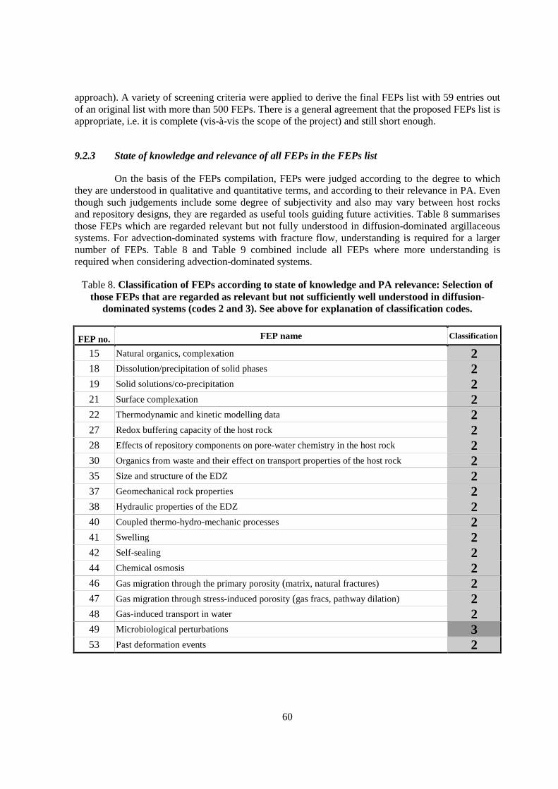
60
approach). A variety of screening criteria were applied to derive the final FEPs list with 59 entries outof an original list with more than 500 FEPs. There is a general agreement that the proposed FEPs list isappropriate, i.e. it is complete (vis-à-vis the scope of the project) and still short enough.
9.2.3 State of knowledge and relevance of all FEPs in the FEPs list
On the basis of the FEPs compilation, FEPs were judged according to the degree to whichthey are understood in qualitative and quantitative terms, and according to their relevance in PA. Eventhough such judgements include some degree of subjectivity and also may vary between host rocksand repository designs, they are regarded as useful tools guiding future activities. Table 8 summarisesthose FEPs which are regarded relevant but not fully understood in diffusion-dominated argillaceoussystems. For advection-dominated systems with fracture flow, understanding is required for a largernumber of FEPs. Table 8 and Table 9 combined include all FEPs where more understanding isrequired when considering advection-dominated systems.
Table 8. Classification of FEPs according to state of knowledge and PA relevance: Selection ofthose FEPs that are regarded as relevant but not sufficiently well understood in diffusion-
dominated systems (codes 2 and 3). See above for explanation of classification codes.
FEP no. FEP name Classification
15 Natural organics, complexation 218 Dissolution/precipitation of solid phases 219 Solid solutions/co-precipitation 221 Surface complexation 222 Thermodynamic and kinetic modelling data 227 Redox buffering capacity of the host rock 228 Effects of repository components on pore-water chemistry in the host rock 230 Organics from waste and their effect on transport properties of the host rock 235 Size and structure of the EDZ 237 Geomechanical rock properties 238 Hydraulic properties of the EDZ 240 Coupled thermo-hydro-mechanic processes 241 Swelling 242 Self-sealing 244 Chemical osmosis 246 Gas migration through the primary porosity (matrix, natural fractures) 247 Gas migration through stress-induced porosity (gas fracs, pathway dilation) 248 Gas-induced transport in water 249 Microbiological perturbations 353 Past deformation events 2
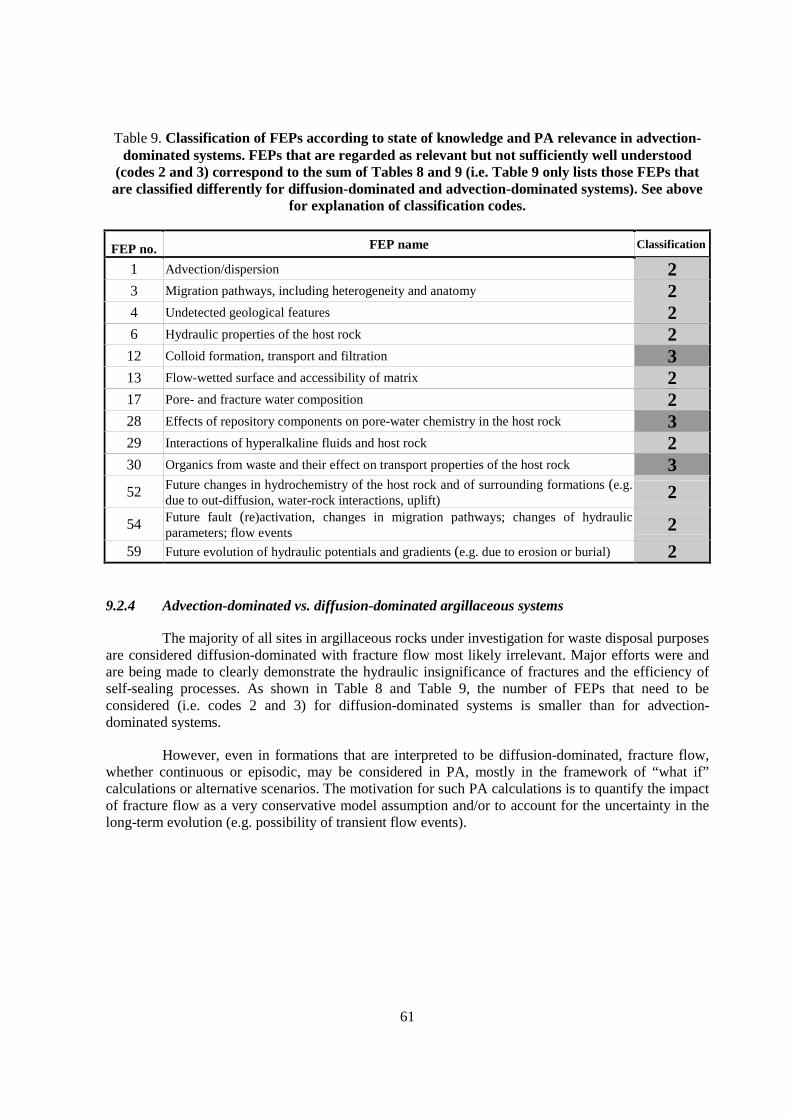
61
Table 9. Classification of FEPs according to state of knowledge and PA relevance in advection-dominated systems. FEPs that are regarded as relevant but not sufficiently well understood
(codes 2 and 3) correspond to the sum of Tables 8 and 9 (i.e. Table 9 only lists those FEPs thatare classified differently for diffusion-dominated and advection-dominated systems). See above
for explanation of classification codes.
FEP no. FEP name Classification
1 Advection/dispersion 23 Migration pathways, including heterogeneity and anatomy 24 Undetected geological features 26 Hydraulic properties of the host rock 2
12 Colloid formation, transport and filtration 313 Flow-wetted surface and accessibility of matrix 217 Pore- and fracture water composition 228 Effects of repository components on pore-water chemistry in the host rock 329 Interactions of hyperalkaline fluids and host rock 230 Organics from waste and their effect on transport properties of the host rock 352 Future changes in hydrochemistry of the host rock and of surrounding formations (e.g.
due to out-diffusion, water-rock interactions, uplift) 2
54 Future fault (re)activation, changes in migration pathways; changes of hydraulicparameters; flow events 2
59 Future evolution of hydraulic potentials and gradients (e.g. due to erosion or burial) 2
9.2.4 Advection-dominated vs. diffusion-dominated argillaceous systems
The majority of all sites in argillaceous rocks under investigation for waste disposal purposesare considered diffusion-dominated with fracture flow most likely irrelevant. Major efforts were andare being made to clearly demonstrate the hydraulic insignificance of fractures and the efficiency ofself-sealing processes. As shown in Table 8 and Table 9, the number of FEPs that need to beconsidered (i.e. codes 2 and 3) for diffusion-dominated systems is smaller than for advection-dominated systems.
However, even in formations that are interpreted to be diffusion-dominated, fracture flow,whether continuous or episodic, may be considered in PA, mostly in the framework of “what if”calculations or alternative scenarios. The motivation for such PA calculations is to quantify the impactof fracture flow as a very conservative model assumption and/or to account for the uncertainty in thelong-term evolution (e.g. possibility of transient flow events).
62
9.2.5 Constraining repository-derived perturbations
Apart from scaling issues, there are other, currently underused ways of applying the hostformations as their own analogues. In some cases, FEPs relating to the far field can be used toconstrain processes expected to occur in the host rock affected by the presence of the repository.Examples of such situations include:
• FEP 50 (Past burial history) can be used to put thermal perturbations derived from therepository into perspective. Specifically, FEPs 31 (Thermal effects on mineral stabilityand pore-water composition) and 33 (Thermally induced consolidation of the host rock)can be dealt with by comparing the thermal impact (maximum temperature and/or time-temperature integral) from the repository with the one experienced by the formationduring natural burial.
• FEP 42 (Self-sealing) relates to a process that occurs both in natural fractures and faultsand in the EDZ. Observations of self-sealing in natural systems provide constraints onthe functionality of this process in the EDZ.
9.2.6 Scaling issues
For a substantial number of FEPs, scaling issues turned out to be relevant. While laboratory-based knowledge is good for many of these FEPs, uncertainties were identified in upscaling theinformation in space and time to the scales appropriate for PA. Promising techniques for upscalinginclude:
• In situ experiments in underground research laboratories (scales intermediate betweenlaboratory and PA)
• Use of the host formation and its past evolution as its own natural analogue. Specifically,some far-field FEPs can be used for upscaling other FEPs. A complete list is given inTable 6.
• Employment of micro-mechanical models for identification and better understanding ofrelevant mechanisms (see Section I, Chapter 7.8).
9.2.7 Demonstration of low permeability and limited relevance of advection
Among the most promising examples of using the host formation as its own natural analogueare profiles of chemical parameters and hydraulic states across the formation. Modelling such profilesprovides constraints on the following features and processes:
• hydraulic conductivity and vertical advective flux across the formation;
• diffusion constants (relevant for the spatial scale of the formation and for very long timescales);
• long-term evolution of the hydraulic and geochemical regime.
The quantification of chemical and hydraulic profiles requires independent information oninitial and boundary conditions, i.e. on the evolution of the aquifers above and below the host
63
formation. At many sites, the degree to which these conditions can be constrained is sufficient toobtain meaningful results and conclusions. At present, chemical profiles provide more quantitativeinformation than hydraulic profiles because the measurement of pore-water pressures in low-permeability systems is lengthy and may be associated with substantial uncertainty.
9.2.8 Geochemical stability
Geochemical stability is one of the more attractive features of argillaceous host rocks. Thisstability is particularly evident in diffusion-dominated systems and has two aspects:
• Because of the fine grain size and relatively long residence times of water in suchformations, chemical reactions of importance to solute transport are generally atequilibrium. Because the chemistry of reactive solutes is generally rock dominated, therock – pore-water system is a robust buffer against repository-induced chemical changes.
• As pointed out in the previous chapter, the rate of evolution of the geochemicalproperties of many potential argillaceous host rocks can be shown to be very slow byinterpreting such characteristics as the Cl distribution in the pore-water itself. Suchinterpretations show that argillaceous formations are also well-buffered against externalgeochemical changes.
9.2.9 Diffusion
Diffusion is the dominant solute transport mechanism in many argillaceous rocks and,through the mechanism of matrix diffusion, can also have a significant retarding effect on the rate ofadvective transport in fractures. Mechanistic understanding of the diffusion of reactive solute ions incharged porous media like clay-rich rock is limited but is sufficient to extend empirical data to supportdiffusion modelling for PA.
9.2.10 Sorption
Sorption of radio-elements and other solute ions contributes positively to the favourabletransport properties of argillaceous rocks. Mechanistic interpretations in terms of ion exchange andsurface complexation processes are useful for interpreting laboratory studies and for geochemicalmodelling of their major-ion chemistry. Solute transport models used to support PA are usually basedon the bulk sorption properties of the formation described using distribution coefficient (Kd) values.
A better mechanistic understanding of the processes of ion exchange and surfacecomplexation, which together determine the sorption properties of a formation, would add confidenceto the time and space extrapolations of empirical sorption parameters that underlie some of the presentgeneration of PA models.

64
9.2.11 Time evolution and geometry of the EDZ, self-sealing
Substantial progress in the structural and hydrogeological characterisation of the EDZ wasachieved in recent years, namely due to in situ work in underground research laboratories and due tomodelling efforts.
• The geotechnical feasibility of tunnelling in argillaceous rocks is undisputed. Detailedrelationships between water content and geomechanical parameters have beenelaborated.
• The geometry and evolution of the EDZ was recognised as a key issue for PA because itmay directly affect the functionality of the repository system.
• Self-sealing is often cited as a primary factor favouring the choice of argillaceousformations as host rocks for deep disposal. Self-sealing mechanisms have been widelyobserved in a variety of argillaceous rocks, and the basic physico-chemical and hydro-mechanical processes leading to self-sealing are reasonably well understood. In plasticclays, self-sealing is expected to be a rather quick process compared to geological timescales. In more indurated argillaceous rocks however, self-sealing is expected to be aslower process. In specific, the kinetics of the self-sealing process in rocks in differentstates of induration may need further attention.
• The use of natural self-sealing should be more heavily exploited (“use of argillaceoushost formations as their own natural analogues”). In many cases, arguments based onnatural observations are more convincing than model calculations.
9.2.12 Stress regime
The stress regime is a FEP relevant for repository construction and operation (e.g. forrepository layout, safety measures) as well as for PA (e.g. for gas migration, possible future faultingand flow along faults, EDZ evolution). Considerable problems exist in the experimental determinationof the in situ stress state in argillaceous rocks. These constitute a material in which the standard stressmeasuring techniques, developed for hard rocks and for soils, are not easily applicable from bothconceptual and technical points of view. An integrated approach with consideration of geological andtechnical stress indicators (e.g. borehole breakouts) and back-analyses (e.g. of convergence behaviourof tunnels in underground research laboratories) is commonly required for a consistent interpretationof in situ stress measurements.
9.3 Potential areas for future studies
On the basis of Section I, Chapters 7 and 8, a number of potentially promising actionsemerged and are documented in Table 10. This table is not a comprehensive list of actions thataddresses all open issues identified in the FEPs compilation (Section II), it is rather a list of potentialactions that are considered promising and could result in major steps towards adequate understanding.The necessity to address the specific themes is variable among different sites due to different disposalconcepts, requirements on the geosphere and regulatory demands.

65
Table 10. Potential areas for future studies in argillaceous media
Theme Objectives Remarks
Abnormal andnormalpressures in thehost formation
• Identification of underlying mechanisms (chemicalosmosis, compaction disequilibrium, horizontal stress,erosion, ...)
• Quantitative evaluation of all relevant mechanisms
• Constraints on large-scale hydraulic conductivity andadvective fluxes (upscaling in space)
• Constraints for the expected long-term evolution(upscaling in time)
• Comparative study integrating all available casestudies in a uniform model framework (consistencycheck)
• Evaluation of uncertainties (e.g. in the choice of initialand boundary conditions)
• The model should explain both the presence ofabnormal pressure at some sites and their absence atother sites
• Observed atseveral sites
• Quantitativeevaluation limitedby uncertainties inhead measurementand resultinghydraulicgradients
• Details seeSection I,Chapter 7.2.1
Natural tracerprofiles acrossargillaceousformations
• Assessment of the relative importance of diffusion andadvection as transport processes (e.g. constraints onvertical advective fluxes)
• Constraints on large-scale diffusion coefficients(upscaling in space)
• Constraints for the expected long-term evolution(upscaling in time)
• Comparative study integrating all available casestudies in a uniform model framework (consistencycheck)
• Evaluation of uncertainties (e.g. in the choice of initialand boundary conditions)
• The model should explain both the presence of spatialvariability of tracer concentrations (or isotopic ratios)at some sites and its absence at other sites
• Suitable dataavailable atseveral sites
• Quantitativeevaluation quitefeasible due tohigh analyticalprecision andavailability ofseveral tracers inthe same profile
• Details seeSection I,Chapter 7.2.2
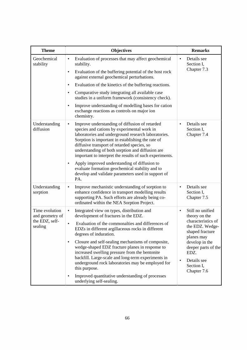
66
Theme Objectives Remarks
Geochemicalstability
• Evaluation of processes that may affect geochemicalstability.
• Evaluation of the buffering potential of the host rockagainst external geochemical perturbations.
• Evaluation of the kinetics of the buffering reactions.
• Comparative study integrating all available casestudies in a uniform framework (consistency check).
• Improve understanding of modelling bases for cationexchange reactions as controls on major ionchemistry.
• Details seeSection I,Chapter 7.3
Understandingdiffusion
• Improve understanding of diffusion of retardedspecies and cations by experimental work inlaboratories and underground research laboratories.Sorption is important in establishing the rate ofdiffusive transport of retarded species, sounderstanding of both sorption and diffusion areimportant to interpret the results of such experiments.
• Apply improved understanding of diffusion toevaluate formation geochemical stability and todevelop and validate parameters used in support ofPA.
• Details seeSection I,Chapter 7.4
Understandingsorption
• Improve mechanistic understanding of sorption toenhance confidence in transport modelling resultssupporting PA. Such efforts are already being co-ordinated within the NEA Sorption Project.
• Details seeSection I,Chapter 7.5
Time evolutionand geometry ofthe EDZ, self-sealing
• Integrated view on types, distribution anddevelopment of fractures in the EDZ.
• Evaluation of the commonalties and differences ofEDZs in different argillaceous rocks in differentdegrees of induration.
• Closure and self-sealing mechanisms of composite,wedge-shaped EDZ fracture planes in response toincreased swelling pressure from the bentonitebackfill. Large-scale and long-term experiments inunderground rock laboratories may be employed forthis purpose.
• Improved quantitative understanding of processesunderlying self-sealing.
• Still no unifiedtheory on thecharacteristics ofthe EDZ. Wedge-shaped fractureplanes maydevelop in thedeeper parts of theEDZ.
• Details seeSection I,Chapter 7.6
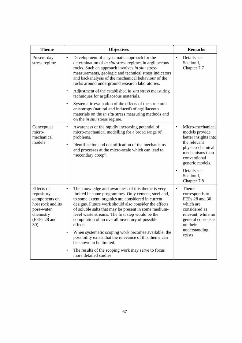
67
Theme Objectives Remarks
Present-daystress regime
• Development of a systematic approach for thedetermination of in situ stress regimes in argillaceousrocks. Such an approach involves in situ stressmeasurements, geologic and technical stress indicatorsand backanalysis of the mechanical behaviour of therocks around underground research laboratories.
• Adjustment of the established in situ stress measuringtechniques for argillaceous materials.
• Systematic evaluation of the effects of the structuralanisotropy (natural and induced) of argillaceousmaterials on the in situ stress measuring methods andon the in situ stress regime.
• Details seeSection I,Chapter 7.7
Conceptualmicro-mechanicalmodels
• Awareness of the rapidly increasing potential ofmicro-mechanical modelling for a broad range ofproblems.
• Identification and quantification of the mechanismsand processes at the micro-scale which can lead to“secondary creep”.
• Micro-mechanicalmodels providebetter insights intothe relevantphysico-chemicalmechanisms thanconventionalgeneric models.
• Details seeSection I,Chapter 7.8
Effects ofrepositorycomponents onhost rock and itspore-waterchemistry(FEPs 28 and30)
• The knowledge and awareness of this theme is verylimited in some programmes. Only cement, steel and,to some extent, organics are considered in currentdesigns. Future work should also consider the effectsof soluble salts that may be present in some medium-level waste streams. The first step would be thecompilation of an overall inventory of possibleeffects.
• When systematic scoping work becomes available, thepossibility exists that the relevance of this theme canbe shown to be limited.
• The results of the scoping work may serve to focusmore detailed studies.
• Themecorresponds toFEPs 28 and 30which areconsidered asrelevant, while nogeneral consensuson theirunderstandingexists
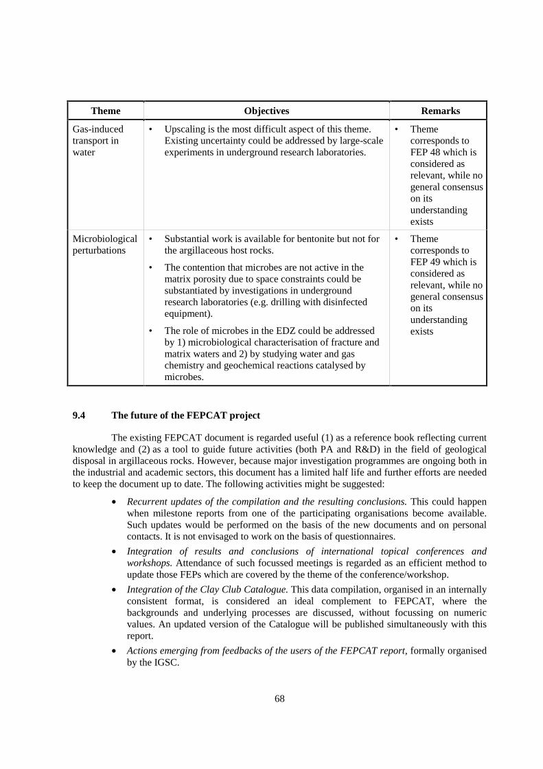
68
Theme Objectives Remarks
Gas-inducedtransport inwater
• Upscaling is the most difficult aspect of this theme.Existing uncertainty could be addressed by large-scaleexperiments in underground research laboratories.
• Themecorresponds toFEP 48 which isconsidered asrelevant, while nogeneral consensuson itsunderstandingexists
Microbiologicalperturbations
• Substantial work is available for bentonite but not forthe argillaceous host rocks.
• The contention that microbes are not active in thematrix porosity due to space constraints could besubstantiated by investigations in undergroundresearch laboratories (e.g. drilling with disinfectedequipment).
• The role of microbes in the EDZ could be addressedby 1) microbiological characterisation of fracture andmatrix waters and 2) by studying water and gaschemistry and geochemical reactions catalysed bymicrobes.
• Themecorresponds toFEP 49 which isconsidered asrelevant, while nogeneral consensuson itsunderstandingexists
9.4 The future of the FEPCAT project
The existing FEPCAT document is regarded useful (1) as a reference book reflecting currentknowledge and (2) as a tool to guide future activities (both PA and R&D) in the field of geologicaldisposal in argillaceous rocks. However, because major investigation programmes are ongoing both inthe industrial and academic sectors, this document has a limited half life and further efforts are neededto keep the document up to date. The following activities might be suggested:
• Recurrent updates of the compilation and the resulting conclusions. This could happenwhen milestone reports from one of the participating organisations become available.Such updates would be performed on the basis of the new documents and on personalcontacts. It is not envisaged to work on the basis of questionnaires.
• Integration of results and conclusions of international topical conferences andworkshops. Attendance of such focussed meetings is regarded as an efficient method toupdate those FEPs which are covered by the theme of the conference/workshop.
• Integration of the Clay Club Catalogue. This data compilation, organised in an internallyconsistent format, is considered an ideal complement to FEPCAT, where thebackgrounds and underlying processes are discussed, without focussing on numericvalues. An updated version of the Catalogue will be published simultaneously with thisreport.
• Actions emerging from feedbacks of the users of the FEPCAT report, formally organisedby the IGSC.
69
10. CORRELATION OF FEPS FROM THE FEPCAT PROJECTWITH THE NEA FEPS DATABASE
An international FEPs database has been developed under the auspices of the NEA and isdocumented in NEA (2000). The scope of this database is much wider than the one considered inFEPCAT. It is a generic database and thus not restricted to argillaceous rocks. Furthermore, itconsiders numerous features and processes that were screened out in FEPCAT, e.g. human actions,climate effects and waste characteristics. The level of detail, however, to which individual processesand characteristics are addressed in the FEPCAT project is higher compared to the NEA FEPsdatabase. For example, there is just one FEP “Host rock”, while numerous FEPs address the host rockin FEPCAT.
As indicated below, the structuring of the NEA FEPs database follows a different logic thanthe one used for FEPCAT. Together with the differing levels of detail of the two projects, this leads tothe fact that in most cases there is no one-to-one correspondence of FEPs in the two databases. This isillustrated by the following examples:
• Several FEPCAT FEPs include aspects that belong to both NEA FEPs groups“Geological environment” and “Contaminant release/migration factors”. This is becausein FEPCAT, one FEP can address both the general characteristics of a FEP in anargillaceous formation as well as the consequences for radionuclide transport, whilethese aspects are separated in the NEA FEPs database. Thus each FEPCAT FEP mayhave more than one correspondence in the NEA FEPs database.
• The FEPs group “Geological environment” in the NEA FEPs database includes bothnatural and repository-induced effects, while these are separated in FEPCAT. Thus theNEA FEPs database makes no distinction between categories A and B of the FEPCATFEPs database, thus several FEPCAT FEPs may relate to just one NEA FEP.
In general, it was found that the NEA FEPs database is comprehensive enough toaccommodate most FEPCAT FEPs at logical positions. An exception are coupled thermo-hydro-mechanical processes which do not have a clear correspondence.
The NEA FEPs database is structured as follows:
0 Assessment basis1 External factors1.1 Repository issues1.2 Geological processes and effects1.3 Climatic processes and effects1.4 Future human actions1.5 Other2. Disposal system domain: environmental factors2.1 Wastes and engineered features2.2 Geological environment
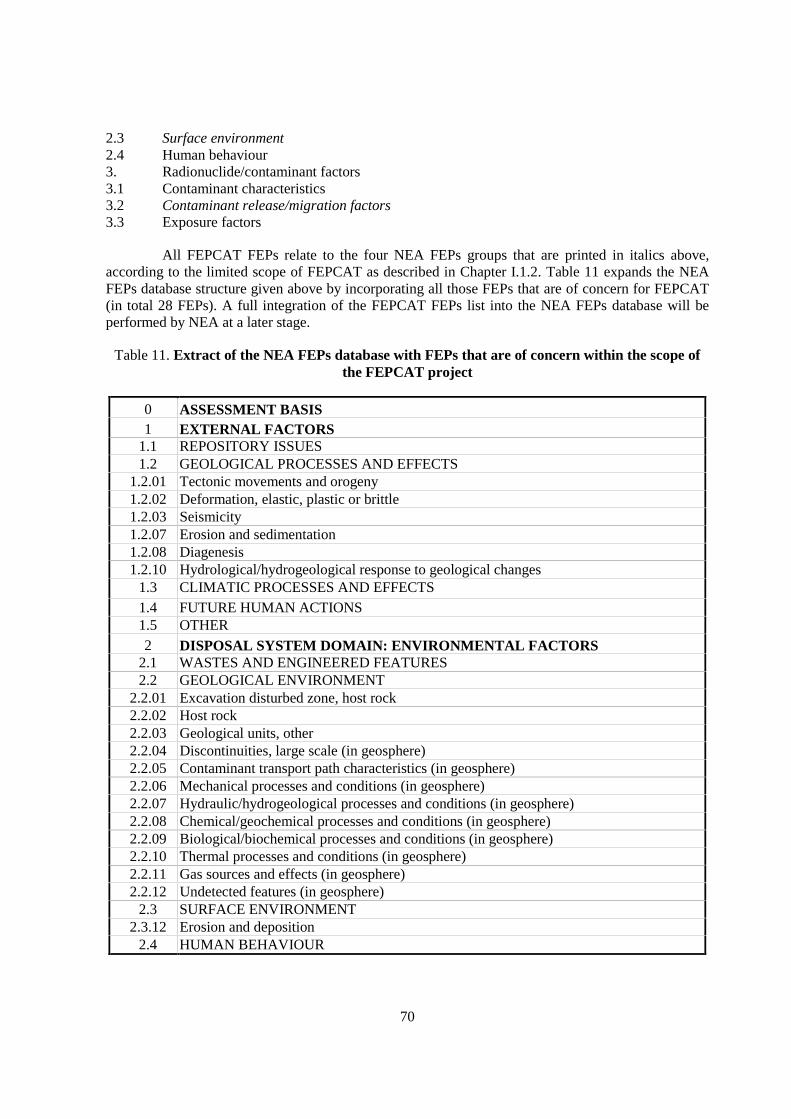
70
2.3 Surface environment2.4 Human behaviour3. Radionuclide/contaminant factors3.1 Contaminant characteristics3.2 Contaminant release/migration factors3.3 Exposure factors
All FEPCAT FEPs relate to the four NEA FEPs groups that are printed in italics above,according to the limited scope of FEPCAT as described in Chapter I.1.2. Table 11 expands the NEAFEPs database structure given above by incorporating all those FEPs that are of concern for FEPCAT(in total 28 FEPs). A full integration of the FEPCAT FEPs list into the NEA FEPs database will beperformed by NEA at a later stage.
Table 11. Extract of the NEA FEPs database with FEPs that are of concern within the scope ofthe FEPCAT project
0 ASSESSMENT BASIS1 EXTERNAL FACTORS
1.1 REPOSITORY ISSUES1.2 GEOLOGICAL PROCESSES AND EFFECTS
1.2.01 Tectonic movements and orogeny1.2.02 Deformation, elastic, plastic or brittle1.2.03 Seismicity1.2.07 Erosion and sedimentation1.2.08 Diagenesis1.2.10 Hydrological/hydrogeological response to geological changes
1.3 CLIMATIC PROCESSES AND EFFECTS1.4 FUTURE HUMAN ACTIONS1.5 OTHER2 DISPOSAL SYSTEM DOMAIN: ENVIRONMENTAL FACTORS
2.1 WASTES AND ENGINEERED FEATURES2.2 GEOLOGICAL ENVIRONMENT
2.2.01 Excavation disturbed zone, host rock2.2.02 Host rock2.2.03 Geological units, other2.2.04 Discontinuities, large scale (in geosphere)2.2.05 Contaminant transport path characteristics (in geosphere)2.2.06 Mechanical processes and conditions (in geosphere)2.2.07 Hydraulic/hydrogeological processes and conditions (in geosphere)2.2.08 Chemical/geochemical processes and conditions (in geosphere)2.2.09 Biological/biochemical processes and conditions (in geosphere)2.2.10 Thermal processes and conditions (in geosphere)2.2.11 Gas sources and effects (in geosphere)2.2.12 Undetected features (in geosphere)
2.3 SURFACE ENVIRONMENT2.3.12 Erosion and deposition
2.4 HUMAN BEHAVIOUR
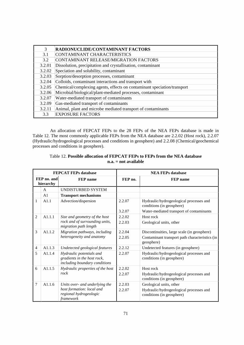
71
3 RADIONUCLIDE/CONTAMINANT FACTORS3.1 CONTAMINANT CHARACTERISTICS3.2 CONTAMINANT RELEASE/MIGRATION FACTORS
3.2.01 Dissolution, precipitation and crystallisation, contaminant3.2.02 Speciation and solubility, contaminant3.2.03 Sorption/desorption processes, contaminant3.2.04 Colloids, contaminant interactions and transport with3.2.05 Chemical/complexing agents, effects on contaminant speciation/transport3.2.06 Microbial/biological/plant-mediated processes, contaminant3.2.07 Water-mediated transport of contaminants3.2.09 Gas-mediated transport of contaminants3.2.11 Animal, plant and microbe mediated transport of contaminants
3.3 EXPOSURE FACTORS
An allocation of FEPCAT FEPs to the 28 FEPs of the NEA FEPs database is made inTable 12. The most commonly applicable FEPs from the NEA database are 2.2.02 (Host rock), 2.2.07(Hydraulic/hydrogeological processes and conditions in geosphere) and 2.2.08 (Chemical/geochemicalprocesses and conditions in geosphere).
Table 12. Possible allocation of FEPCAT FEPs to FEPs from the NEA databasen.a. = not available
FEPCAT FEPs database NEA FEPs database
FEP no. andhierarchy
FEP name FEP no. FEP name
A UNDISTURBED SYSTEMA1 Transport mechanisms
1 A1.1 Advection/dispersion 2.2.07
3.2.07
Hydraulic/hydrogeological processes andconditions (in geosphere)Water-mediated transport of contaminants
2 A1.1.1 Size and geometry of the hostrock and of surrounding units,migration path length
2.2.022.2.03
Host rockGeological units, other
3 A1.1.2 Migration pathways, includingheterogeneity and anatomy
2.2.042.2.05
Discontinuities, large scale (in geosphere)Contaminant transport path characteristics (ingeosphere)
4 A1.1.3 Undetected geological features 2.2.12 Undetected features (in geosphere)5 A1.1.4 Hydraulic potentials and
gradients in the host rock,including boundary conditions
2.2.07 Hydraulic/hydrogeological processes andconditions (in geosphere)
6 A1.1.5 Hydraulic properties of the hostrock
2.2.022.2.07
Host rockHydraulic/hydrogeological processes andconditions (in geosphere)
7 A1.1.6 Units over- and underlying thehost formation: local andregional hydrogeologicframework
2.2.032.2.07
Geological units, otherHydraulic/hydrogeological processes andconditions (in geosphere)

72
FEPCAT FEPs database NEA FEPs database
FEP no. andhierarchy
FEP name FEP no. FEP name
A1.2 Diffusion8 A1.2.1 Diffusivity 2.2.02
2.2.08
3.2.07
Host rockChemical/geochemical processes andconditions (in geosphere)Water-mediated transport of contaminants
9 A1.2.2 Connected matrix porosity 2.2.02 Host rock10 A1.2.3 Ion exclusion 2.2.02
2.2.08Host rockChemical/geochemical processes andconditions (in geosphere)
11 A1.2.4 Surface diffusion 2.2.08
3.2.07
Chemical/geochemical processes andconditions (in geosphere)Water-mediated transport of contaminants
12 A1.3 Colloid formation, transport andfiltration
3.2.04 Colloids, contaminant interactions andtransport with
A2 Retardation mechanismsA2.1 Matrix diffusion
8 A2.1.1 Diffusivity 2.2.022.2.08
3.2.07
Host rockChemical/geochemical processes andconditions (in geosphere)Water-mediated transport of contaminants
9 A2.1.2 Connected matrix porosity 2.2.02 Host rock13 A2.1.3 Flow-wetted surface and
accessibility of matrix2.2.05 Contaminant transport path characteristics (in
geosphere)10 A2.1.4 Ion exclusion 2.2.02
2.2.08Host rockChemical/geochemical processes andconditions (in geosphere)
11 A2.1.5 Surface diffusion 2.2.08
3.2.07
Chemical/geochemical processes andconditions (in geosphere)Water-mediated transport of contaminants
A2.2 Sorption (broad definition)14 A2.2.1 Lithology, mineralogy of rocks
and fracture infills2.2.022.2.08
Host rockChemical/geochemical processes andconditions (in geosphere)
15 A2.2.2 Natural organics, complexation 2.2.022.2.08
3.2.05
Host rockChemical/geochemical processes andconditions (in geosphere)Chemical/complexing agents, effects oncontaminant speciation/transport
16 A2.2.3 Mineral-surface area 2.2.02 Host rock17 A2.2.4 Pore- and fracture water
composition2.2.08
3.2.02
Chemical/geochemical processes andconditions (in geosphere)Speciation and solubility, contaminant
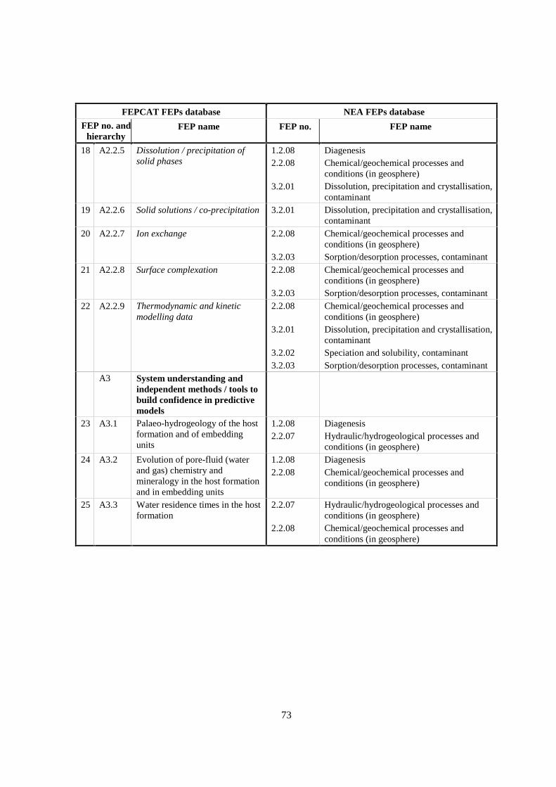
73
FEPCAT FEPs database NEA FEPs database
FEP no. andhierarchy
FEP name FEP no. FEP name
18 A2.2.5 Dissolution / precipitation ofsolid phases
1.2.082.2.08
3.2.01
DiagenesisChemical/geochemical processes andconditions (in geosphere)Dissolution, precipitation and crystallisation,contaminant
19 A2.2.6 Solid solutions / co-precipitation 3.2.01 Dissolution, precipitation and crystallisation,contaminant
20 A2.2.7 Ion exchange 2.2.08
3.2.03
Chemical/geochemical processes andconditions (in geosphere)Sorption/desorption processes, contaminant
21 A2.2.8 Surface complexation 2.2.08
3.2.03
Chemical/geochemical processes andconditions (in geosphere)Sorption/desorption processes, contaminant
22 A2.2.9 Thermodynamic and kineticmodelling data
2.2.08
3.2.01
3.2.023.2.03
Chemical/geochemical processes andconditions (in geosphere)Dissolution, precipitation and crystallisation,contaminantSpeciation and solubility, contaminantSorption/desorption processes, contaminant
A3 System understanding andindependent methods / tools tobuild confidence in predictivemodels
23 A3.1 Palaeo-hydrogeology of the hostformation and of embeddingunits
1.2.082.2.07
DiagenesisHydraulic/hydrogeological processes andconditions (in geosphere)
24 A3.2 Evolution of pore-fluid (waterand gas) chemistry andmineralogy in the host formationand in embedding units
1.2.082.2.08
DiagenesisChemical/geochemical processes andconditions (in geosphere)
25 A3.3 Water residence times in the hostformation
2.2.07
2.2.08
Hydraulic/hydrogeological processes andconditions (in geosphere)Chemical/geochemical processes andconditions (in geosphere)

74
FEPCAT FEPs database NEA FEPs database
FEP no. andhierarchy
FEP name FEP no. FEP name
B REPOSITORY-INDUCEDPERTURBATIONS
B1 Chemical perturbations26 B1.1 Oxidation of the host rock 2.2.08 Chemical/geochemical processes and
conditions (in geosphere)27 B1.1.1 Redox buffering capacity of the
host rock2.2.022.2.08
Host rockChemical/geochemical processes andconditions (in geosphere)
28 B1.2 Effects of repository componentson pore-water chemistry in thehost rock
2.2.08
3.2.023.2.05
Chemical/geochemical processes andconditions (in geosphere)Speciation and solubility, contaminantChemical/complexing agents, effects oncontaminant speciation/transport
29 B1.2.1 Interactions of hyperalkalinefluids and host rock
2.2.08
3.2.023.2.05
Chemical/geochemical processes andconditions (in geosphere)Speciation and solubility, contaminantChemical/complexing agents, effects oncontaminant speciation/transport
30 B1.2.2 Organics from waste and theireffect on transport properties ofthe host rock
2.2.08
3.2.05
Chemical/geochemical processes andconditions (in geosphere)Chemical/complexing agents, effects oncontaminant speciation/transport
B2 Thermal perturbations31 B2.1 Thermal effects on mineral
stability and pore-watercomposition
2.2.08
2.2.10
Chemical/geochemical processes andconditions (in geosphere)Thermal processes and conditions (ingeosphere)
32 B2.2 Thermal rock properties 2.2.022.2.10
Host rockThermal processes and conditions (ingeosphere)
33 B2.3 Thermally induced consolidationof the host rock
n.a. n.a.
B3 Geomechanical perturbations34 B3.1 Geomechanical stability 2.2.06 Mechanical processes and conditions (in
geosphere)35 B3.2 Size and structure of the EDZ 2.2.01 Excavation disturbed zone, host rock36 B3.3 Effects of bentonite swelling on
the host rock2.2.06 Mechanical processes and conditions (in
geosphere)37 B3.4 Geomechanical rock properties 2.2.02
2.2.06Host rockMechanical processes and conditions (ingeosphere)
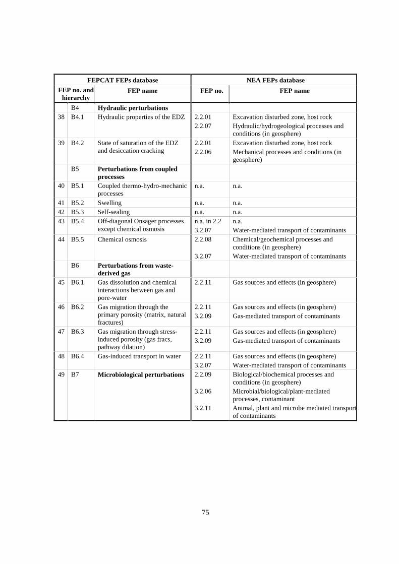
75
FEPCAT FEPs database NEA FEPs database
FEP no. andhierarchy
FEP name FEP no. FEP name
B4 Hydraulic perturbations38 B4.1 Hydraulic properties of the EDZ 2.2.01
2.2.07Excavation disturbed zone, host rockHydraulic/hydrogeological processes andconditions (in geosphere)
39 B4.2 State of saturation of the EDZand desiccation cracking
2.2.012.2.06
Excavation disturbed zone, host rockMechanical processes and conditions (ingeosphere)
B5 Perturbations from coupledprocesses
40 B5.1 Coupled thermo-hydro-mechanicprocesses
n.a. n.a.
41 B5.2 Swelling n.a. n.a.42 B5.3 Self-sealing n.a. n.a.43 B5.4 Off-diagonal Onsager processes
except chemical osmosisn.a. in 2.23.2.07
n.a.Water-mediated transport of contaminants
44 B5.5 Chemical osmosis 2.2.08
3.2.07
Chemical/geochemical processes andconditions (in geosphere)Water-mediated transport of contaminants
B6 Perturbations from waste-derived gas
45 B6.1 Gas dissolution and chemicalinteractions between gas andpore-water
2.2.11 Gas sources and effects (in geosphere)
46 B6.2 Gas migration through theprimary porosity (matrix, naturalfractures)
2.2.113.2.09
Gas sources and effects (in geosphere)Gas-mediated transport of contaminants
47 B6.3 Gas migration through stress-induced porosity (gas fracs,pathway dilation)
2.2.113.2.09
Gas sources and effects (in geosphere)Gas-mediated transport of contaminants
48 B6.4 Gas-induced transport in water 2.2.113.2.07
Gas sources and effects (in geosphere)Water-mediated transport of contaminants
49 B7 Microbiological perturbations 2.2.09
3.2.06
3.2.11
Biological/biochemical processes andconditions (in geosphere)Microbial/biological/plant-mediatedprocesses, contaminantAnimal, plant and microbe mediated transportof contaminants

76
FEPCAT FEPs database NEA FEPs database
FEP no. andhierarchy
FEP name FEP no. FEP name
C LONG-TERM EVOLUTIONC1 DiagenesisC1.1 Past basin evolution
23 C1.1.1 Palaeo-hydrogeology of the hostformation and of the embeddingunits
1.2.082.2.07
DiagenesisHydraulic/hydrogeological processes andconditions (in geosphere)
24 C1.1.2 Evolution of pore-fluid (waterand gas) chemistry andmineralogy in the host formationand in embedding units
1.2.082.2.08
DiagenesisChemical/geochemical processes andconditions (in geosphere)
50 C1.1.3 Past burial history 1.2.071.2.082.3.12
Erosion and sedimentationDiagenesisErosion and deposition
C1.2 Ongoing and future processes51 C1.2.1 Present and future geothermal
regime and related processes2.2.10 Thermal processes and conditions (in
geosphere)52 C1.2.2 Future changes in
hydrochemistry of the host rockand of surrounding formations(e.g. due to out-diffusion, water-rock interactions, uplift)
2.2.08 Chemical/geochemical processes andconditions (in geosphere)
C2 Deformation events53 C2.1 Past deformation events 1.2.01
1.2.021.2.032.2.04
Tectonic movements and orogenyDeformation, elastic, plastic or brittleSeismicityDiscontinuities, large scale (in geosphere)
54 C2.2 Future fault (re)activation,changes in migration pathways;changes of hydraulic parameters;flow events
1.2.011.2.021.2.031.2.10
2.2.05
2.2.07
Tectonic movements and orogenyDeformation, elastic, plastic or brittleSeismicityHydrological/hydrogeological response togeological changesContaminant transport path characteristics (ingeosphere)Hydraulic/hydrogeological processes andconditions (in geosphere)
41 C2.3 Swelling n.a. n.a.42 C2.4 Self-sealing n.a. n.a.55 C2.5 Present-day stress regime 2.2.06 Mechanical processes and conditions (in
geosphere)56 C2.6 Future stress regime 2.2.06 Mechanical processes and conditions (in
geosphere)
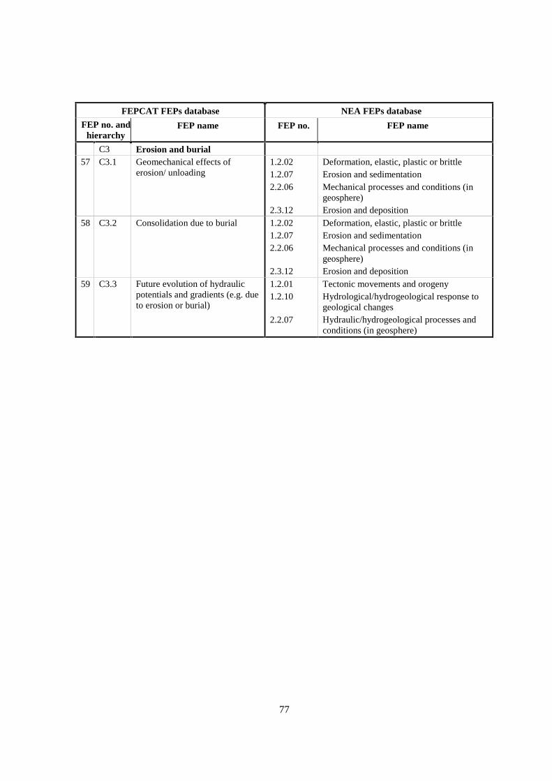
77
FEPCAT FEPs database NEA FEPs database
FEP no. andhierarchy
FEP name FEP no. FEP name
C3 Erosion and burial57 C3.1 Geomechanical effects of
erosion/ unloading1.2.021.2.072.2.06
2.3.12
Deformation, elastic, plastic or brittleErosion and sedimentationMechanical processes and conditions (ingeosphere)Erosion and deposition
58 C3.2 Consolidation due to burial 1.2.021.2.072.2.06
2.3.12
Deformation, elastic, plastic or brittleErosion and sedimentationMechanical processes and conditions (ingeosphere)Erosion and deposition
59 C3.3 Future evolution of hydraulicpotentials and gradients (e.g. dueto erosion or burial)
1.2.011.2.10
2.2.07
Tectonic movements and orogenyHydrological/hydrogeological response togeological changesHydraulic/hydrogeological processes andconditions (in geosphere)

79
SECTION II
FEPs Compilation


81
Section II of the report compiles and summarises the information provided by theparticipating organisations in the questionnaires and in interviews. Thus there is no rigorous ambitionof completeness, even though the Expert Group attempted to include all key information. For eachFEP, the compilation is structured as follows:
1. Definition and generalities: Defines the FEP and clarifies its scope. Definitions of terms areincluded where appropriate.
2. Site-specific experimental information: Both the types of investigation methods and theresults and conclusions are addressed. In many cases, the relevant questionnaire informationis organised in table format. Field data, laboratory experiments, in situ experiments inboreholes or underground research laboratories as well as modelling studies are included. Ifappropriate, information of generic type or relating to rock formations that are not addressedotherwise in this report may also be included (e.g. natural analogues, examples from thescientific literature).
3. Scaling issues: Addresses the spatial and temporal scales to which the experimentalinformation is related and compares them with the scales required for PA. If needed,comments are made on the upscaling of experimental data and findings (in the broadestsense) to PA scales.
4. Scientific level of understanding: Provides a judgement on how well a FEP is understoodqualitatively and quantitatively, irrespective of how it is used (or not used) in PA.
5. Linked FEPs: Provides a list of FEPs which are usfeul to evaluate, understand, quantifyand/or constrain the consequences of the FEP under discussion. In contrast, the list does notrefer to FEPs which the FEP under discussion affects. The choice of linked FEPs depends onseveral factors that are difficult to standardise or quantify (e.g. rock type, repository design,degree of linkage). Thus the list should not be over-interpreted and should be used only as arough guidance. Due to the definition above, the total matrix of linkages is not symmetric.This means that FEP A may be linked to FEP B but not FEP B to FEP A. For example,FEP 33 (B2.3; Thermally induced consolidation of the host rock) is linked to FEP 50(C1.1.3; Past burial history) because the latter is important to judge the extent to which therock may consolidate in response to heat emitted from the waste. Here, one importantquestion is “How much does the waste-derived thermal pulse exceed the temperature that theformation experienced during natural burial?”. On the other hand, FEP 50 does not depend atall on repository effects such as the one dealt with in FEP 33.
6. Level of understanding from a PA perspective and treatment in PA: The requirements tounderstand a FEP for PA purposes are in many cases substantially more limited than thosewhich would be desirable from an academic point of view. Some FEPs may be ignored ortreated in a conservative way without having full scientific understanding. Empiricapproaches (e.g. sorption Kds) can in many cases shown to be sufficient for PA purposes,without having a detailed and quantifiable understanding of the underlying mechanisticprinciples.
7. Available reviews: Addresses reviews pertinent to specific sites, to the entire wastemanagement community as well as to milestones in the scientific literature.
8. Planned work: Overview of planned activities that could be used to co-ordinate future effortsin specific fields.
9. Overall evaluation: Short summary of the key points of the compilation.

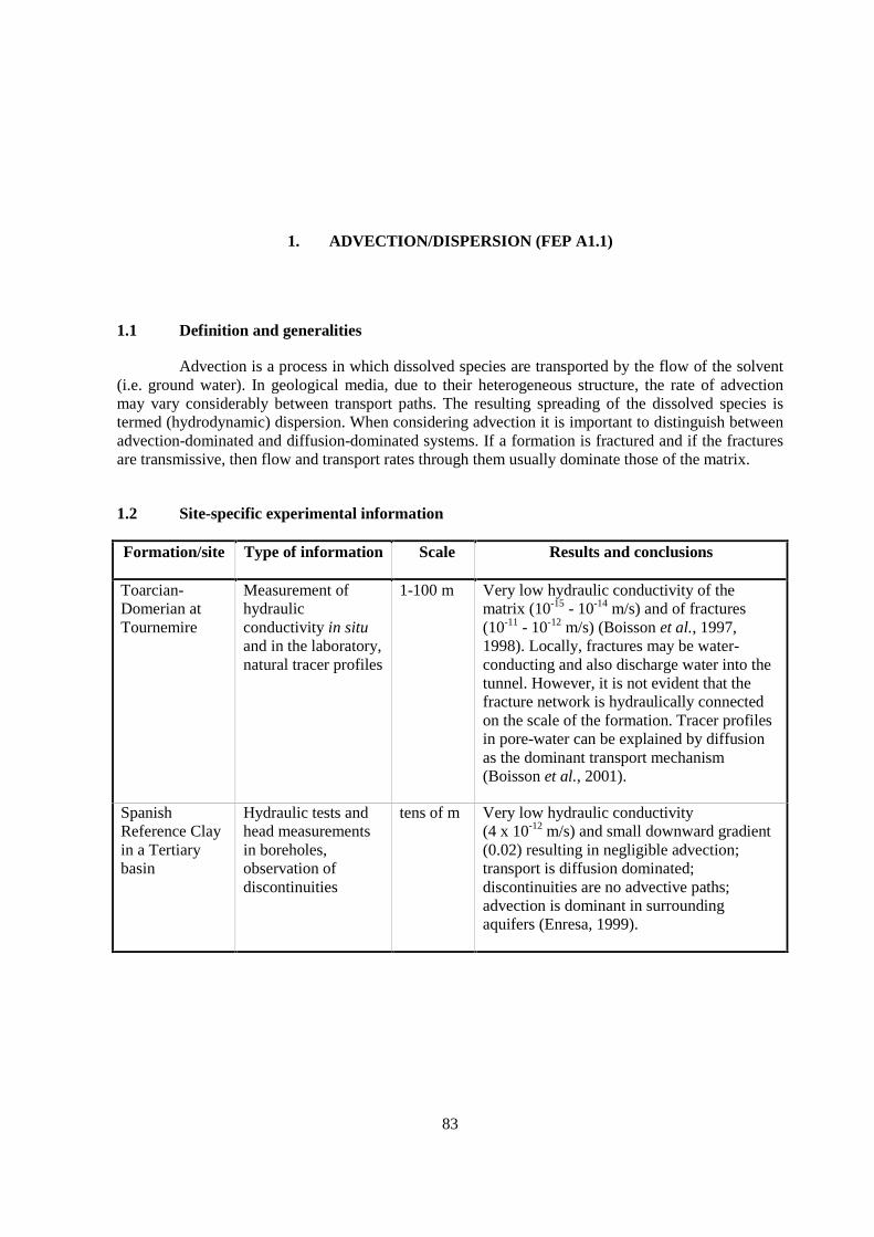
83
1. ADVECTION/DISPERSION (FEP A1.1)
1.1 Definition and generalities
Advection is a process in which dissolved species are transported by the flow of the solvent(i.e. ground water). In geological media, due to their heterogeneous structure, the rate of advectionmay vary considerably between transport paths. The resulting spreading of the dissolved species istermed (hydrodynamic) dispersion. When considering advection it is important to distinguish betweenadvection-dominated and diffusion-dominated systems. If a formation is fractured and if the fracturesare transmissive, then flow and transport rates through them usually dominate those of the matrix.
1.2 Site-specific experimental information
Formation/site Type of information Scale Results and conclusions
Toarcian-Domerian atTournemire
Measurement ofhydraulicconductivity in situand in the laboratory,natural tracer profiles
1-100 m Very low hydraulic conductivity of thematrix (10-15 - 10-14 m/s) and of fractures(10-11 - 10-12 m/s) (Boisson et al., 1997,1998). Locally, fractures may be water-conducting and also discharge water into thetunnel. However, it is not evident that thefracture network is hydraulically connectedon the scale of the formation. Tracer profilesin pore-water can be explained by diffusionas the dominant transport mechanism(Boisson et al., 2001).
SpanishReference Clayin a Tertiarybasin
Hydraulic tests andhead measurementsin boreholes,observation ofdiscontinuities
tens of m Very low hydraulic conductivity(4 x 10-12 m/s) and small downward gradient(0.02) resulting in negligible advection;transport is diffusion dominated;discontinuities are no advective paths;advection is dominant in surroundingaquifers (Enresa, 1999).
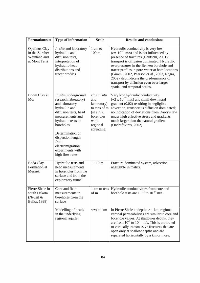
84
Formation/site Type of information Scale Results and conclusions
Opalinus Clayin the ZürcherWeinland andat Mont Terri
In situ and laboratoryhydraulic anddiffusion tests,interpretation ofhydraulic-headdistributions andtracer profiles
1 cm to100 m
Hydraulic conductivity is very low(ca. 10-13 m/s) and is not influenced bypresence of fractures (Gautschi, 2001);transport is diffusion dominated. Hydraulicoverpressures in the Benken borehole andtracer profiles in pore-water at both locations(Gimmi, 2002, Pearson et al., 2003, Nagra,2002) also indicate the predominance oftransport by diffusion even over largerspatial and temporal scales.
Boom Clay atMol
In situ (undergroundresearch laboratory)and laboratoryhydraulic anddiffusion tests, headmeasurements andhydraulic tests inboreholes
Determination ofdispersion lengthfromelectromigrationexperiments withhigh flow rates
cm (in situandlaboratory)to tens of m(in situ),boreholeswithregionalspreading
Very low hydraulic conductivity(~2 x 10-12 m/s) and small downwardgradient (0.02) resulting in negligibleadvection; transport is diffusion dominated;no indication of deviations from Darcy's lawunder high effective stress and gradientsmuch larger than the natural gradient(Ondraf/Niras, 2002).
Boda ClayFormation atMecsek
Hydraulic tests andhead measurementsin boreholes from thesurface and from theexploratory tunnel
1 - 10 m Fracture-dominated system, advectionnegligible in matrix.
Pierre Shale insouth Dakota(Neuzil &Belitz, 1998)
Core and fieldmeasurements inboreholes from thesurface
1 cm to tensof m
Hydraulic conductivities from core andborehole tests are 10-13 to 10-14 m/s.
Modelling of headsin the underlyingregional aquifer
several km In Pierre Shale at depths > 1 km, regionalvertical permeabilities are similar to core andborehole values. At shallower depths, theyare from 10-9 to 10-11 m/s. This is attributedto vertically transmissive fractures that areopen only at shallow depths and areseparated horizontally by a km or more.
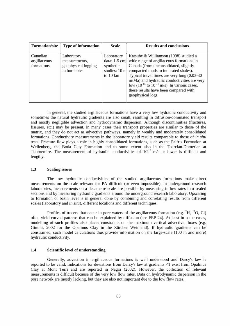
85
Formation/site Type of information Scale Results and conclusions
Canadianargillaceousformations
Laboratorymeasurements,geophysical loggingin boreholes
Laboratorydata: 1-5 cm;syntheticstudies: 10 mto 10 km
Katsube & Williamson (1998) studied awide range of argillaceous formations inCanada (from unconsolidated, slightlycompacted muds to indurated shales).Typical travel times are very long (0.03-30m/Ma) and hydraulic conductivities are verylow (10-15 to 10-11 m/s). In various cases,these results have been compared withgeophysical logs.
In general, the studied argillaceous formations have a very low hydraulic conductivity andsometimes the natural hydraulic gradients are also small, resulting in diffusion-dominated transportand mostly negligible advection and hydrodynamic dispersion. Although discontinuities (fractures,fissures, etc.) may be present, in many cases their transport properties are similar to those of thematrix, and they do not act as advective pathways, namely in weakly and moderately consolidatedformations. Conductivity measurements in the laboratory yield results comparable to those of in situtests. Fracture flow plays a role in highly consolidated formations, such as the Palfris Formation atWellenberg, the Boda Clay Formation and to some extent also in the Toarcian-Domerian atTournemire. The measurement of hydraulic conductivities of 10-12 m/s or lower is difficult andlengthy.
1.3 Scaling issues
The low hydraulic conductivities of the studied argillaceous formations make directmeasurements on the scale relevant for PA difficult (or even impossible). In underground researchlaboratories, measurements on a decametre scale are possible by measuring inflow rates into sealedsections and by measuring hydraulic gradients around the underground research laboratory. Upscalingto formation or basin level is in general done by combining and correlating results from differentscales (laboratory and in situ), different locations and different techniques.
Profiles of tracers that occur in pore-waters of the argillaceous formation (e.g. 2H, 18O, Cl)often yield curved patterns that can be explained by diffusion (see FEP 24). At least in some cases,modelling of such profiles also places constraints on the maximum vertical advective fluxes (e.g.Gimmi, 2002 for the Opalinus Clay in the Zürcher Weinland). If hydraulic gradients can beconstrained, such model calculations thus provide information on the large-scale (100 m and more)hydraulic conductivity.
1.4 Scientific level of understanding
Generally, advection in argillaceous formations is well understood and Darcy's law isreported to be valid. Indications for deviations from Darcy's law at gradients <1 exist from OpalinusClay at Mont Terri and are reported in Nagra (2002). However, the collection of relevantmeasurements is difficult because of the very low flow rates. Data on hydrodynamic dispersion in thepore network are mostly lacking, but they are also not important due to the low flow rates.
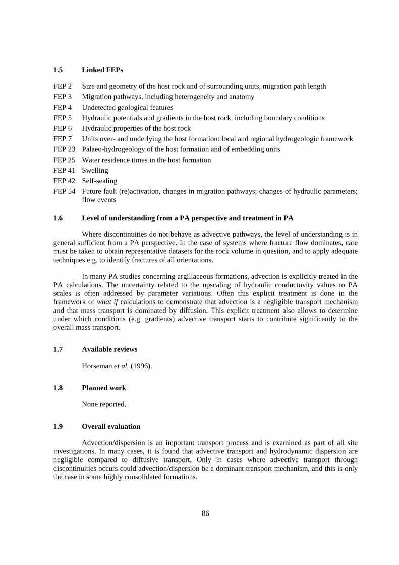
86
1.5 Linked FEPs
FEP 2 Size and geometry of the host rock and of surrounding units, migration path length
FEP 3 Migration pathways, including heterogeneity and anatomy
FEP 4 Undetected geological features
FEP 5 Hydraulic potentials and gradients in the host rock, including boundary conditions
FEP 6 Hydraulic properties of the host rock
FEP 7 Units over- and underlying the host formation: local and regional hydrogeologic framework
FEP 23 Palaeo-hydrogeology of the host formation and of embedding units
FEP 25 Water residence times in the host formation
FEP 41 Swelling
FEP 42 Self-sealing
FEP 54 Future fault (re)activation, changes in migration pathways; changes of hydraulic parameters;flow events
1.6 Level of understanding from a PA perspective and treatment in PA
Where discontinuities do not behave as advective pathways, the level of understanding is ingeneral sufficient from a PA perspective. In the case of systems where fracture flow dominates, caremust be taken to obtain representative datasets for the rock volume in question, and to apply adequatetechniques e.g. to identify fractures of all orientations.
In many PA studies concerning argillaceous formations, advection is explicitly treated in thePA calculations. The uncertainty related to the upscaling of hydraulic conductuvity values to PAscales is often addressed by parameter variations. Often this explicit treatment is done in theframework of what if calculations to demonstrate that advection is a negligible transport mechanismand that mass transport is dominated by diffusion. This explicit treatment also allows to determineunder which conditions (e.g. gradients) advective transport starts to contribute significantly to theoverall mass transport.
1.7 Available reviews
Horseman et al. (1996).
1.8 Planned work
None reported.
1.9 Overall evaluation
Advection/dispersion is an important transport process and is examined as part of all siteinvestigations. In many cases, it is found that advective transport and hydrodynamic dispersion arenegligible compared to diffusive transport. Only in cases where advective transport throughdiscontinuities occurs could advection/dispersion be a dominant transport mechanism, and this is onlythe case in some highly consolidated formations.

87
2. SIZE AND GEOMETRY OF THE HOST ROCK AND OF SURROUNDING UNITS,PATH LENGTH (FEP A1.1.1)
2.1 Definition and generalities
PA-relevant characteristics of the system geometry include the depth, thickness andhomogeneity of the host rock and the nature of the surrounding formations. The characterisation ofhost rock thickness and heterogeneity provides information on the advective or diffusive path lengthfor contaminant release.
2.2 Site-specific experimental information
Formation/site
Type ofinformation Results and conclusions
Callovo-Oxfordianat Bure
2D seismic survey(15 km2), 3-Dseismic survey(4 km2, with seismicattributes), deepboreholes over ca.10 km2. Oildrillings,reprocessedseismics and surfaceoutcrops consideredin an area with aradius of 20-25 kmaround theundergroundresearch laboratory(under construction)
Flat-lying sedimentary sequence dipping 1-1.5° to NW. Nofaulting with vertical displacements >5 m observed within anarea of 5 km around the underground research laboratory. Knownfaults (Gondrecourt, E; Marne, W) bound the investigation area.The thickness of the Callovo-Oxfordian varies between 130 m inthe SE to 145 m in the NNW, and is 133 m at the site of theunderground research laboratory. It is over- and underlain bylimestone units. At the site of the underground researchlaboratory, its depth is between ca. 422 and 552 m.
The Marne fault is located 20 km W of the underground researchlaboratory, has a NW-SE strike and dips to NE. It is a recurrentlyreactivated basement fault, and the vertical displacement of theCallovo-Oxfordian is 60 - 80 m.
The Gondrecourt graben is located 5 km E of the undergroundresearch laboratory, strikes NE-SW and is ca. 1-2 km wide.Vertical displacement is ca. 60 m in the Jurassic.
The Callovo-Oxfordian is directly over- and underlain bylimestone units (Oxfordian and Middle Jurassic), which haveaquifer properties near the surface but are less transmissive in theexploratory boreholes around the underground researchlaboratory site (K <3 x 10⁻⁷ m/s, Babot 1999).
Reference: Trouiller & Lebon (1999).
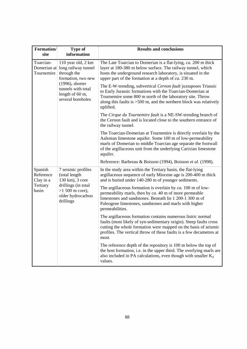
88
Formation/site
Type ofinformation
Results and conclusions
Toarcian-Domerian atTournemire
110 year old, 2 kmlong railway tunnelthrough theformation, two new(1996), shortertunnels with totallength of 60 m,several boreholes
The Late Toarcian to Domerian is a flat-lying, ca. 200 m thicklayer at 180-380 m below surface. The railway tunnel, whichhosts the underground research laboratory, is situated in theupper part of the formation at a depth of ca. 230 m.
The E-W-trending, subvertical Cernon fault juxtaposes Triassicto Early Jurassic formations with the Toarcian-Domerian atTournemire some 800 m north of the laboratory site. Throwalong this faults is >500 m, and the northern block was relativelyuplifted.
The Cirque du Tournemire fault is a NE-SW-trending branch ofthe Cernon fault and is located close to the southern entrance ofthe railway tunnel.
The Toarcian-Domerian at Tournemire is directly overlain by theAalenian limestone aquifer. Some 100 m of low-permeabilitymarls of Domerian to middle Toarcian age separate the footwallof the argillaceous unit from the underlying Carixian limestoneaquifer.
Reference: Barbreau & Boisson (1994), Boisson et al. (1998).
SpanishReferenceClay in aTertiarybasin
7 seismic profiles(total length130 km), 3 coredrillings (in total>1 500 m core),older hydrocarbondrillings
In the study area within the Tertiary basin, the flat-lyingargillaceous sequence of early Miocene age is 200-400 m thickand is buried under 140-280 m of younger sediments.
The argillaceous formation is overlain by ca. 100 m of low-permeability marls, then by ca. 40 m of more permeablelimestones and sandstones. Beneath lie 1 200-1 300 m ofPaleogene limestones, sandstones and marls with higherpermeabilities.
The argillaceous formation contains numerous listric normalfaults (most likely of syn-sedimentary origin). Steep faults crosscutting the whole formation were mapped on the basis of seismicprofiles. The vertical throw of these faults is a few decametres atmost.
The reference depth of the repository is 100 m below the top ofthe host formation, i.e. in the upper third. The overlying marls arealso included in PA calculations, even though with smaller Kd
values.
89
Formation/site
Type ofinformation
Results and conclusions
OpalinusClay at MontTerri
Geometricdefinition of rockunits based on
• Surfacemapping
• boreholesdrilled fromthe surface
• 2 paralleltunnels +researchlaboratorytunnel
• numerousboreholesdrilled fromthe tunnels andfrom theresearchlaboratory
• balanced cross-sections
The underground research laboratory is located in an anticline ofthe Folded Jura Mountains. Folding occurred at 12-5 Ma b.p.,and the area has been uplifting since 10 Ma. The thickness ofOpalinus Clay is 160 m and includes an aberrant 5-10 m thicksandy-calcareous facies, which disappears towards E butbecomes thicker towards W (Franche Comté). The depth range inthe research laboratory is 230-320 m below surface.
The Main Fault (>70 m long, occurs in 2 tunnels + researchlaboratory, ca. 1 m thick) is considered to be a relativelyinsignificant structure. 2D balanced cross-sections indicate that itpossibly ends within the Opalinus Clay on its upper side; itsbottom is most likely connected to a larger thrust.
Sandy limestones (Early Dogger) in the hanging wall and marls(Late Liassic) in the footwall are local aquifers.
References: Thury & Bossart (1999), Wermeille & Bossart(1999).
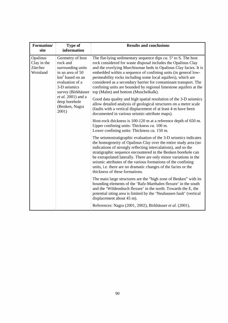
90
Formation/site
Type ofinformation
Results and conclusions
OpalinusClay in theZürcherWeinland
Geometry of hostrock andsurrounding unitsin an area of 50km2 based on anevaluation of a3-D seismicssurvey (Birkhäuseret al. 2001) and adeep borehole(Benken, Nagra2001)
The flat-lying sedimentary sequence dips ca. 5° to S. The hostrock considered for waste disposal includes the Opalinus Clayand the overlying Murchisonae beds in Opalinus Clay facies. It isembedded within a sequence of confining units (in general low-permeability rocks including some local aquifers), which areconsidered as a secondary barrier for contaminant transport. Theconfining units are bounded by regional limestone aquifers at thetop (Malm) and bottom (Muschelkalk).
Good data quality and high spatial resolution of the 3-D seismicsallow detailed analysis of geological structures on a metre scale(faults with a vertical displacement of at least 4 m have beendocumented in various seismic-attribute maps).
Host-rock thickness is 100-120 m at a reference depth of 650 m.Upper confining units: Thickness ca. 100 m.Lower confining units: Thickness ca. 150 m.
The seismostratigraphic evaluation of the 3-D seismics indicatesthe homogeneity of Opalinus Clay over the entire study area (noindications of strongly reflecting intercalations), and so thestratigraphic sequence encountered in the Benken borehole canbe extrapolated laterally. There are only minor variations in theseismic attributes of the various formations of the confiningunits, i.e. there are no dramatic changes of the facies or thethickness of these formations.
The main large structures are the “high zone of Benken” with itsbounding elements of the ‘Rafz-Marthalen flexure’ in the southand the ‘Wildensbuch flexure’ in the north. Towards the E, thepotential siting area is limited by the ‘Neuhausen fault’ (verticaldisplacement about 45 m).
References: Nagra (2001, 2002), Birkhäuser et al. (2001).

91
Formation/site
Type ofinformation
Results and conclusions
Boom Clayat Mol
Geological maps,boreholes (cored &uncored),geophysicallogging data, high-resolution seismiccampaigns, studiesin clay pits,trenches,undergroundresearch laboratory
The Boom Clay was deposited in the Campine Basin in thenorth-eastern part of Belgium. It dips gently (<1°) to NNE and ischaracterised by a high lateral continuity. It crops out in thesouthern part of the Campine Basin and reaches a depth of about400 m in the north. In the Roer Valley Graben in the outmost NEpart of the Campine Basin, the Boom Clay is present at a fargreater depth. In the vicinity of Mol, the clay formation is about100 m thick. It is sandwiched between more permeable, sandyformations.
The Boom Clay was investigated by several seismic campaignson a regional scale (2D-seismic campaign PLM 1984 by theGeol. Survey of Belgium), and on a local scale: 3-D-seismiccampaign 78-ON in the nuclear zone of Mol/Dessel (1978), a testline in 1991 (91-ON) and 65 km of high-resolution 2D-seismicscovering an area of 15 km by 15 km around and inside thenuclear zone (96-ON). Three boreholes were drilled in thenuclear zone of Mol/Dessel: Dessel-1 (1993) and the coredboreholes SCK-15 (1975) and Mol-1 (1997). .
References: Demyttenaere & Laga (1988), Wouters &Vandenberghe (1994).
Yper Clay atDoel
Geological maps,boreholes, studiesin clay pits,offshore and canalseismicinvestigations
The Ypresian Clays were deposited in the northern and westernpart of Belgium. They dip gently (<1°) to NNE, reaching athickness of 150 m, and occur at a depth of more than 600 m onthe northern Belgian border. Their vertical and horizontalcontinuity is more variable when compared to Boom Clay. TheYpresian clays are composed of 4 members, characterised by adifferent lithologies (some are silty), and tend to become moresandy to the east. So the Moen Clay disappears to the east ofAntwerpen, where it is known as the Mons-en-Pévèle Sand.
Reference: LTGH-University Gent (1996).
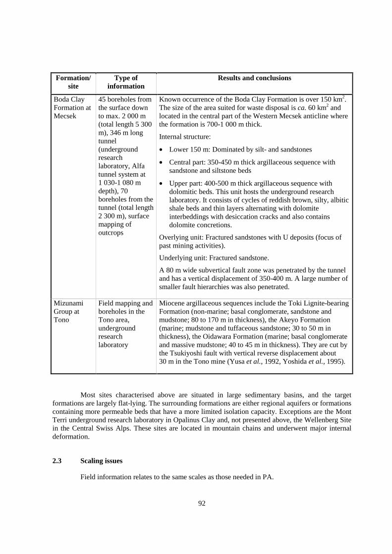
92
Formation/site
Type ofinformation
Results and conclusions
Boda ClayFormation atMecsek
45 boreholes fromthe surface downto max. 2 000 m(total length 5 300m), 346 m longtunnel(undergroundresearchlaboratory, Alfatunnel system at1 030-1 080 mdepth), 70boreholes from thetunnel (total length2 300 m), surfacemapping ofoutcrops
Known occurrence of the Boda Clay Formation is over 150 km2.The size of the area suited for waste disposal is ca. 60 km2 andlocated in the central part of the Western Mecsek anticline wherethe formation is 700-1 000 m thick.
Internal structure:
• Lower 150 m: Dominated by silt- and sandstones
• Central part: 350-450 m thick argillaceous sequence withsandstone and siltstone beds
• Upper part: 400-500 m thick argillaceous sequence withdolomitic beds. This unit hosts the underground researchlaboratory. It consists of cycles of reddish brown, silty, albiticshale beds and thin layers alternating with dolomiteinterbeddings with desiccation cracks and also containsdolomite concretions.
Overlying unit: Fractured sandstones with U deposits (focus ofpast mining activities).
Underlying unit: Fractured sandstone.
A 80 m wide subvertical fault zone was penetrated by the tunneland has a vertical displacement of 350-400 m. A large number ofsmaller fault hierarchies was also penetrated.
MizunamiGroup atTono
Field mapping andboreholes in theTono area,undergroundresearchlaboratory
Miocene argillaceous sequences include the Toki Lignite-bearingFormation (non-marine; basal conglomerate, sandstone andmudstone; 80 to 170 m in thickness), the Akeyo Formation(marine; mudstone and tuffaceous sandstone; 30 to 50 m inthickness), the Oidawara Formation (marine; basal conglomerateand massive mudstone; 40 to 45 m in thickness). They are cut bythe Tsukiyoshi fault with vertical reverse displacement about30 m in the Tono mine (Yusa et al., 1992, Yoshida et al., 1995).
Most sites characterised above are situated in large sedimentary basins, and the targetformations are largely flat-lying. The surrounding formations are either regional aquifers or formationscontaining more permeable beds that have a more limited isolation capacity. Exceptions are the MontTerri underground research laboratory in Opalinus Clay and, not presented above, the Wellenberg Sitein the Central Swiss Alps. These sites are located in mountain chains and underwent major internaldeformation.
2.3 Scaling issues
Field information relates to the same scales as those needed in PA.

93
2.4 Scientific level of understanding
Knowledge of the large-scale geometry is, in general, sufficiently well understood for bothscientific and PA purposes.
2.5 Linked FEPs
FEP 3 Migration pathways, including heterogeneity and anatomy
FEP 4 Undetected geological features
FEP 7 Units over- and underlying the host formation: local and regional hydrogeologic framework
FEP 50 Past burial history
FEP 53 Past deformation events
FEP 54 Future fault (re)activation, changes in migration pathways; changes of hydraulic parameters;flow events
2.6 Level of understanding from a PA perspective and treatment in PA
In host formations in which fracture flow is of low relevance, some transport-relevantparameters (such as diffusion coefficients and hydraulic conductivities) are anisotropic, with highervalues parallel to bedding (i.e. in subhorizontal directions). Transport through such formations willoccur laterally to some degree, thus the transport path lengths are expected to be longer whencompared to the most direct route out of the formation. Nevertheless, for PA purposes, the mostconservative assumption is made by assuming vertical upward transport. Discontinuities such as faultsmay be included explicitly in PA calculations. This is mostly done in alternative or "what-if" casesbecause such discontinuities have either not been identified in the target areas or have been shown tohave no relevance for flow and transport (see FEP 3).
For formations where fracture flow is important, transport through them may be modelledexplicitly. Alternatively, fluid flow can be simulated using an equivalent porous medium approachwith average hydraulic conductivities higher than those of the matrix itself. Simulating transport withan equivalent porous medium model is done using very low flow porosities which lead to the hightransport rates typical of flow in fractures.
The role of the surrounding units in PA is mostly limited to dilution. In some cases,surrounding units are included explicitly in PA calculations but in a simplified way (e.g. homogeneouslayers). In other cases, they are ignored for the sake of conservatism; i.e. radionuclides released fromthe host formation are thought to be instantaneously transported into the regional aquifers.
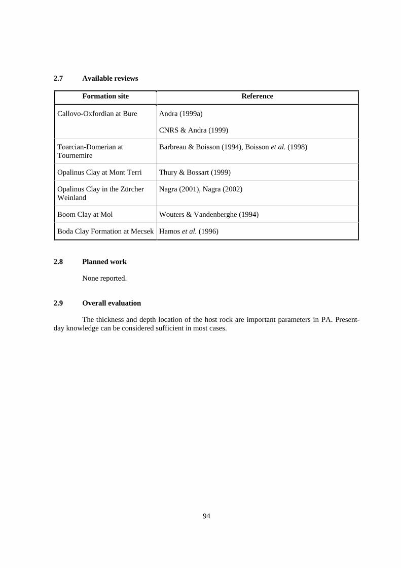
94
2.7 Available reviews
Formation site Reference
Callovo-Oxfordian at Bure Andra (1999a)
CNRS & Andra (1999)
Toarcian-Domerian atTournemire
Barbreau & Boisson (1994), Boisson et al. (1998)
Opalinus Clay at Mont Terri Thury & Bossart (1999)
Opalinus Clay in the ZürcherWeinland
Nagra (2001), Nagra (2002)
Boom Clay at Mol Wouters & Vandenberghe (1994)
Boda Clay Formation at Mecsek Hamos et al. (1996)
2.8 Planned work
None reported.
2.9 Overall evaluation
The thickness and depth location of the host rock are important parameters in PA. Present-day knowledge can be considered sufficient in most cases.
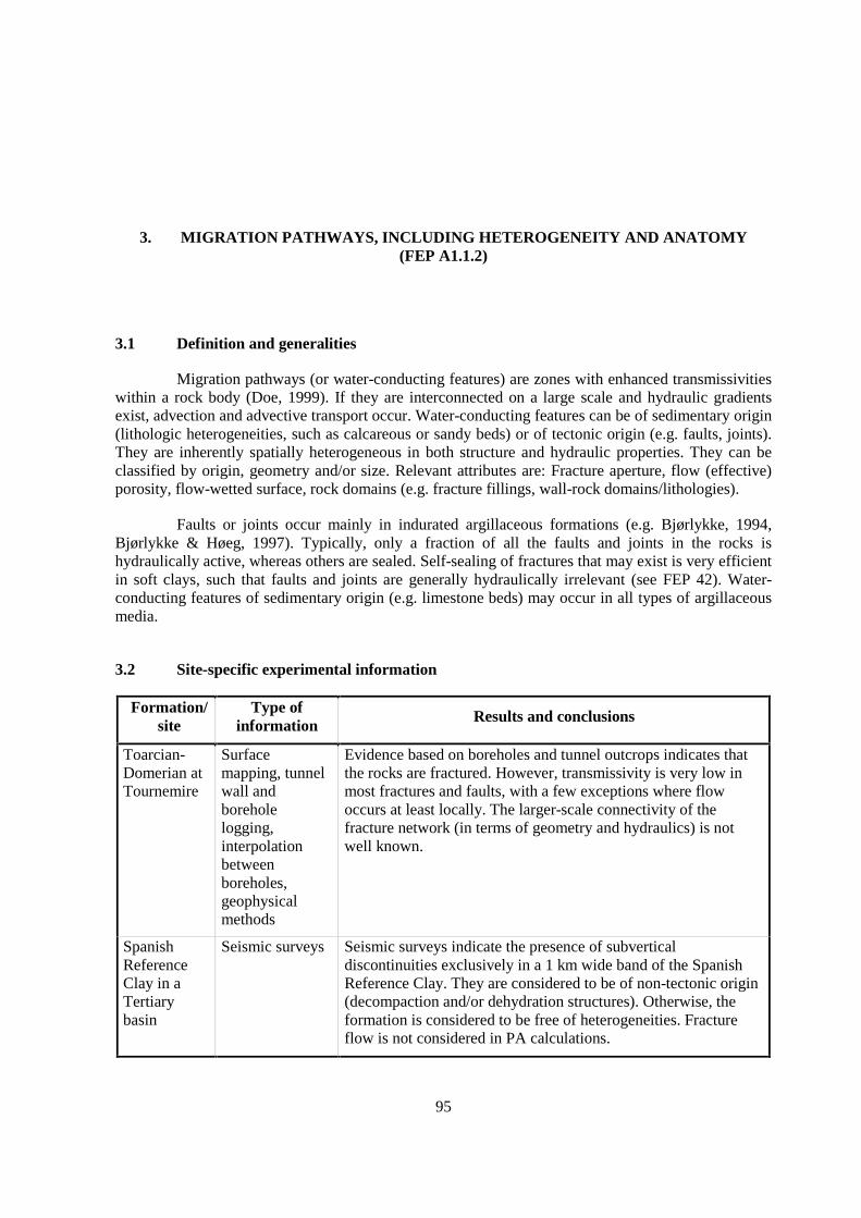
95
3. MIGRATION PATHWAYS, INCLUDING HETEROGENEITY AND ANATOMY(FEP A1.1.2)
3.1 Definition and generalities
Migration pathways (or water-conducting features) are zones with enhanced transmissivitieswithin a rock body (Doe, 1999). If they are interconnected on a large scale and hydraulic gradientsexist, advection and advective transport occur. Water-conducting features can be of sedimentary origin(lithologic heterogeneities, such as calcareous or sandy beds) or of tectonic origin (e.g. faults, joints).They are inherently spatially heterogeneous in both structure and hydraulic properties. They can beclassified by origin, geometry and/or size. Relevant attributes are: Fracture aperture, flow (effective)porosity, flow-wetted surface, rock domains (e.g. fracture fillings, wall-rock domains/lithologies).
Faults or joints occur mainly in indurated argillaceous formations (e.g. Bjørlykke, 1994,Bjørlykke & Høeg, 1997). Typically, only a fraction of all the faults and joints in the rocks ishydraulically active, whereas others are sealed. Self-sealing of fractures that may exist is very efficientin soft clays, such that faults and joints are generally hydraulically irrelevant (see FEP 42). Water-conducting features of sedimentary origin (e.g. limestone beds) may occur in all types of argillaceousmedia.
3.2 Site-specific experimental information
Formation/site
Type ofinformation
Results and conclusions
Toarcian-Domerian atTournemire
Surfacemapping, tunnelwall andboreholelogging,interpolationbetweenboreholes,geophysicalmethods
Evidence based on boreholes and tunnel outcrops indicates thatthe rocks are fractured. However, transmissivity is very low inmost fractures and faults, with a few exceptions where flowoccurs at least locally. The larger-scale connectivity of thefracture network (in terms of geometry and hydraulics) is notwell known.
SpanishReferenceClay in aTertiarybasin
Seismic surveys Seismic surveys indicate the presence of subverticaldiscontinuities exclusively in a 1 km wide band of the SpanishReference Clay. They are considered to be of non-tectonic origin(decompaction and/or dehydration structures). Otherwise, theformation is considered to be free of heterogeneities. Fractureflow is not considered in PA calculations.
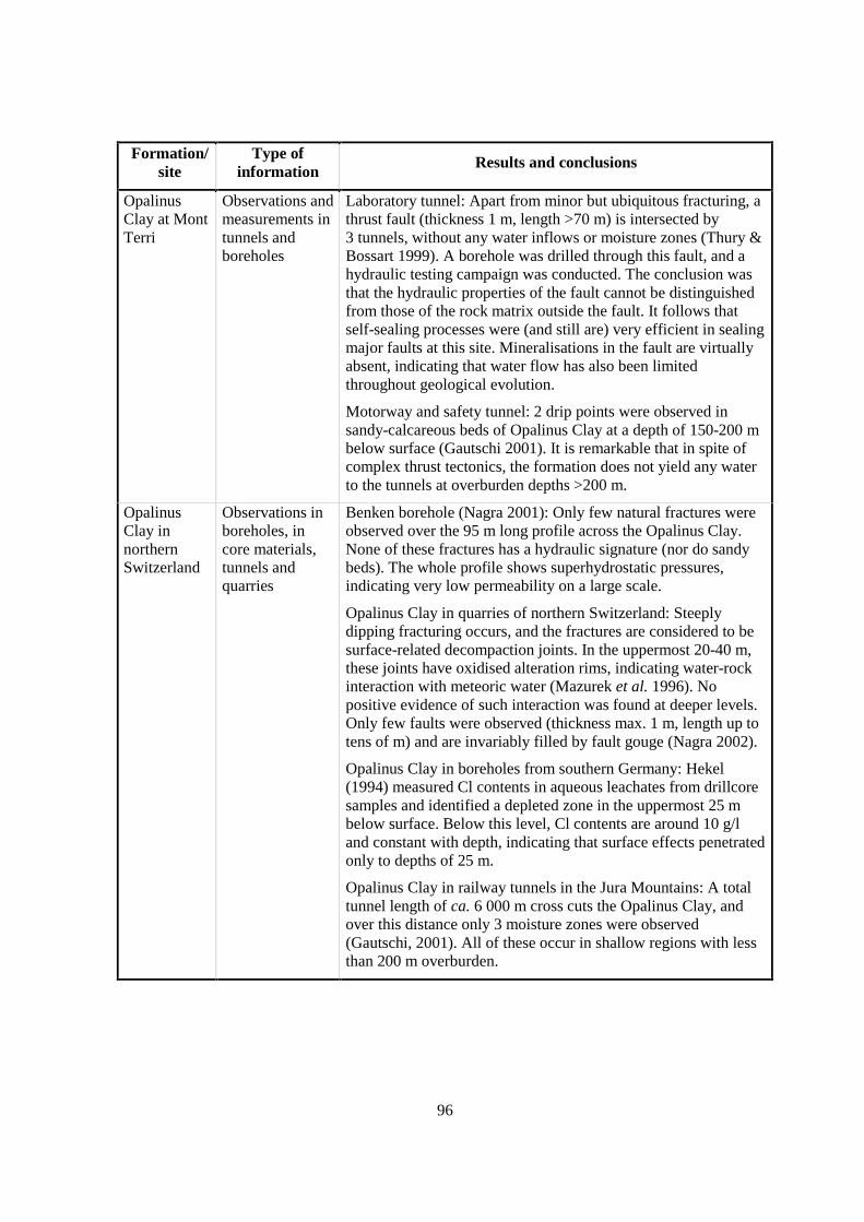
96
Formation/site
Type ofinformation
Results and conclusions
OpalinusClay at MontTerri
Observations andmeasurements intunnels andboreholes
Laboratory tunnel: Apart from minor but ubiquitous fracturing, athrust fault (thickness 1 m, length >70 m) is intersected by3 tunnels, without any water inflows or moisture zones (Thury &Bossart 1999). A borehole was drilled through this fault, and ahydraulic testing campaign was conducted. The conclusion wasthat the hydraulic properties of the fault cannot be distinguishedfrom those of the rock matrix outside the fault. It follows thatself-sealing processes were (and still are) very efficient in sealingmajor faults at this site. Mineralisations in the fault are virtuallyabsent, indicating that water flow has also been limitedthroughout geological evolution.
Motorway and safety tunnel: 2 drip points were observed insandy-calcareous beds of Opalinus Clay at a depth of 150-200 mbelow surface (Gautschi 2001). It is remarkable that in spite ofcomplex thrust tectonics, the formation does not yield any waterto the tunnels at overburden depths >200 m.
OpalinusClay innorthernSwitzerland
Observations inboreholes, incore materials,tunnels andquarries
Benken borehole (Nagra 2001): Only few natural fractures wereobserved over the 95 m long profile across the Opalinus Clay.None of these fractures has a hydraulic signature (nor do sandybeds). The whole profile shows superhydrostatic pressures,indicating very low permeability on a large scale.
Opalinus Clay in quarries of northern Switzerland: Steeplydipping fracturing occurs, and the fractures are considered to besurface-related decompaction joints. In the uppermost 20-40 m,these joints have oxidised alteration rims, indicating water-rockinteraction with meteoric water (Mazurek et al. 1996). Nopositive evidence of such interaction was found at deeper levels.Only few faults were observed (thickness max. 1 m, length up totens of m) and are invariably filled by fault gouge (Nagra 2002).
Opalinus Clay in boreholes from southern Germany: Hekel(1994) measured Cl contents in aqueous leachates from drillcoresamples and identified a depleted zone in the uppermost 25 mbelow surface. Below this level, Cl contents are around 10 g/land constant with depth, indicating that surface effects penetratedonly to depths of 25 m.
Opalinus Clay in railway tunnels in the Jura Mountains: A totaltunnel length of ca. 6 000 m cross cuts the Opalinus Clay, andover this distance only 3 moisture zones were observed(Gautschi, 2001). All of these occur in shallow regions with lessthan 200 m overburden.
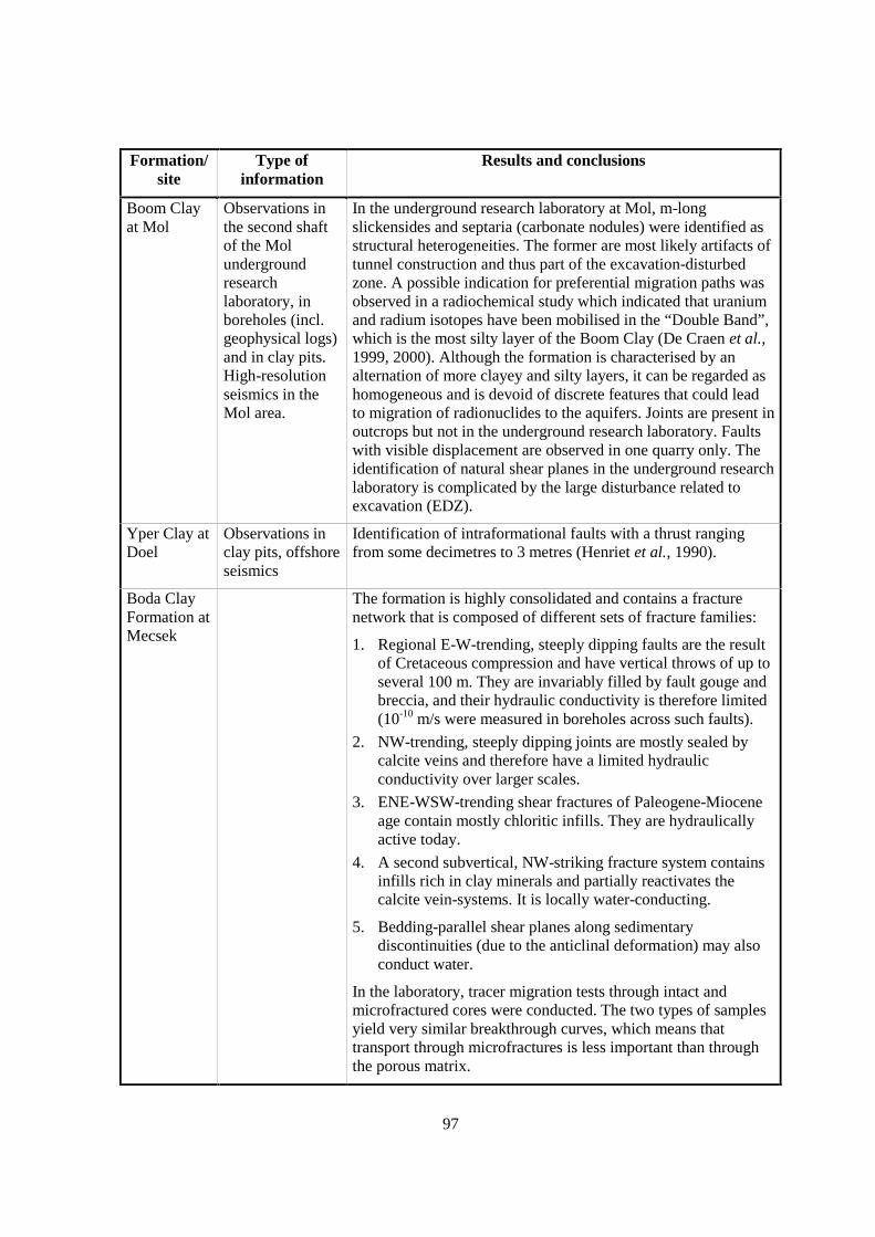
97
Formation/site
Type ofinformation
Results and conclusions
Boom Clayat Mol
Observations inthe second shaftof the Molundergroundresearchlaboratory, inboreholes (incl.geophysical logs)and in clay pits.High-resolutionseismics in theMol area.
In the underground research laboratory at Mol, m-longslickensides and septaria (carbonate nodules) were identified asstructural heterogeneities. The former are most likely artifacts oftunnel construction and thus part of the excavation-disturbedzone. A possible indication for preferential migration paths wasobserved in a radiochemical study which indicated that uraniumand radium isotopes have been mobilised in the “Double Band”,which is the most silty layer of the Boom Clay (De Craen et al.,1999, 2000). Although the formation is characterised by analternation of more clayey and silty layers, it can be regarded ashomogeneous and is devoid of discrete features that could leadto migration of radionuclides to the aquifers. Joints are present inoutcrops but not in the underground research laboratory. Faultswith visible displacement are observed in one quarry only. Theidentification of natural shear planes in the underground researchlaboratory is complicated by the large disturbance related toexcavation (EDZ).
Yper Clay atDoel
Observations inclay pits, offshoreseismics
Identification of intraformational faults with a thrust rangingfrom some decimetres to 3 metres (Henriet et al., 1990).
Boda ClayFormation atMecsek
The formation is highly consolidated and contains a fracturenetwork that is composed of different sets of fracture families:
1. Regional E-W-trending, steeply dipping faults are the resultof Cretaceous compression and have vertical throws of up toseveral 100 m. They are invariably filled by fault gouge andbreccia, and their hydraulic conductivity is therefore limited(10-10 m/s were measured in boreholes across such faults).
2. NW-trending, steeply dipping joints are mostly sealed bycalcite veins and therefore have a limited hydraulicconductivity over larger scales.
3. ENE-WSW-trending shear fractures of Paleogene-Mioceneage contain mostly chloritic infills. They are hydraulicallyactive today.
4. A second subvertical, NW-striking fracture system containsinfills rich in clay minerals and partially reactivates thecalcite vein-systems. It is locally water-conducting.
5. Bedding-parallel shear planes along sedimentarydiscontinuities (due to the anticlinal deformation) may alsoconduct water.
In the laboratory, tracer migration tests through intact andmicrofractured cores were conducted. The two types of samplesyield very similar breakthrough curves, which means thattransport through microfractures is less important than throughthe porous matrix.
98
3.3 Scaling issues
Small-scale heterogeneities down to a few centimetres can be detected in outcrops, on tunnelwalls and in cores, larger ones (>10 cm) in wireline logs. Faults with vertical throws larger than a fewmetres are visible in high-quality seismic profiles. However, the large-scale hydraulic characteristicsof such water-conducting features are difficult to study, unless they were penetrated by boreholes ortunnels. In general, major features, if present, are avoided in most repository designs, thus no detailedcharacterisation is required from a PA viewpoint.
If only vertical boreholes are available, steeply dipping discontinuities may not be detected.If vertical displacements along them are small, they will also not be identified by seismic tools.Surface outcrops, e.g. in clay pits, are suited to fill this gap. A robust characterisation becomesavailable in the later stages of a site characterisation project, i.e. when a underground laboratory isbuilt.
The large-scale hydraulic characteristics of discrete discontinuities, whether observeddirectly or not, can in many cases be constrained by the quantitative interpretation of head profiles(hydraulic disequilibria, i.e. under- or overpressures) and profiles of geochemical tracers, such as He,Cl, 37Cl, 18O and 2H in pore-water (see FEP 24).
3.4 Scientific level of understanding
In general, sedimentary heterogeneities are well understood. With respect to theunderstanding of tectonic structures on different scales and their significance for migration, thespectrum of judgements is heterogeneous. One of the main difficulties is the upscaling of geologicaland hydraulic observations made on small scales (boreholes, tunnels) to PA-relevant scales (seeabove).
3.5 Linked FEPs
FEP 4 Undetected geological features
FEP 14 Lithology, mineralogy of rocks and fracture infills
FEP 18 Dissolution/precipitation of solid phases
FEP 41 Swelling
FEP 42 Self-sealing
FEP 53 Past deformation events
FEP 54 Future fault (re)activation, changes in migration pathways; changes of hydraulic parameters;flow events
3.6 Level of understanding from a PA perspective and treatment in PA
At all considered sites, sedimentary heterogeneities are regarded as well understood and notcritical to PA. On the other hand, the explorability and PA significance of tectonic features is a matterof debate in the case of indurated (often over-consolidated) formations, less so in the case of plasticclays. Some good indications exist that faults are hydraulically insignificant in argillaceous
99
formations. However, in some cases the data base is limited, such that it is difficult to rigorouslydemonstrate the irrelevance of tectonic structures for flow and transport.
Other open questions include:
1. Spatial heterogeneity and large-scale anatomy of tectonic water-conducting features, namelyfaults, and their conceptualisation;
2. Scaling rules of faults;
3. Relevance of episodic deformation and flow events (FEP 54).
The PA approaches are fundamentally different for soft and fractured clay formations:
• Soft clays, such as the Boom Clay and the Spanish Reference Clay, are considered to bediffusion-dominated, with a negligible contribution of fracture flow. The diffusion-dispersion model is applied for PA calculations. Known fractured zones, whetherhydraulically active or not (e.g. in the Spanish Reference Clay), are avoided byrepository design.
• Indurated clay formations, such as the Boda Clay Formation, are assumed to bedominated by fracture flow, and thus a double-porosity approach is used.
• Formations in an intermediate stage of induration are the Opalinus Clay and the Callovo-Oxfordian at Bure. While evidence exists that these formations are diffusion-dominated(hydraulic evidence, natural tracer profiles), (over)conservative assumptions about theexistence of long, interconnected, water-conducting fractures can be explored inalternative or what-if model calculations of radionuclide transport.
3.7 Available reviews
Formation/site Reference
Generic NEA (1998a,b)
Callovo-Oxfordian at Bure Andra (1999a)
Toarcian-Domerian atTournemire
Boisson et al. (1998), Cabrera (2001)
Opalinus Clay at Mont Terri Thury & Bossart (1999)
Opalinus Clay in the ZürcherWeinland
Nagra (2001), Nagra (2002)
Boom Clay at Mol Wouters & Vandenberghe (1994)
Boda Clay Formation at Mecsek Hamos et al. (1996)
100
3.8 Planned work
Boom Clay at Mol: Analysis of large-scale heterogeneities (e.g. slickensides, joints) inoutcrops and in the underground research laboratory. Special processing of available seismics.
3.9 Overall evaluation
The understanding of tectonic migration pathways, including their geometry and hydraulicsignificance, is generally regarded as moderate to very good, depending on the degree of detail of thesite investigations. Apart from further structural characterisation, indirect evidence (e.g. palaeo-hydrogeological arguments, environmental tracers) may help to understand transport through theformations. Fracture flow is unlikely in soft clays but may dominate transport in highly induratedargillaceous formations.
101
4. UNDETECTED GEOLOGICAL FEATURES (FEP A1.1.3)
4.1 Definition and generalities
This FEP relates to features that cannot currently be observed because of the lack ofappropriate techniques, or features that were not detected yet because of insufficient studies.
4.2 Site-specific experimental information
Sedimentary heterogeneities, such as lateral changes in facies, are expected to occur on aregional scale and are generally well constrained by information from boreholes and surface outcrops.They are not regarded as sources of major uncertainty. The situation is less clear for tectonicheterogeneities. Faults in seismic surveys are only recognised if their vertical throw at the bottomand/or top of the target formation exceeds 5-10 m. If the faulting mechanism was dominated by strike-slip, even major faults may stay undetected prior to drilling or tunnelling activities. In highly induratedargillaceous formations, such faults may play a role as migration pathways. However, they do notdisrupt the lateral continuity of the formation whose thickness is at least one order of magnitude largerthan the seismic detection limit. At least in the case of the Opalinus Clay of the Zürcher Weinland, allfaults mapped on the surface have a vertical component of displacement, i.e. pure strike-slip faultswere not observed.
In the national programmes aimed at the characterisation of disposal sites or undergroundresearch laboratories, no example exists where the initial conceptual model of the site had to bechanged substantially due to the later discovery of new features.
Indirect evidence suggesting the existence of undetected features is documented in the PierreShale (North America). In this formation, different in situ methods were used to measure hydraulicconductivity, resulting in values of 10-14-10-13 m/s (Neuzil, 1986, 1993). In contrast, regionalsimulations of a system of multiple aquifers and confining units in south Dakota yields values of10-9 m/s, i.e. 4-5 orders of magnitude higher than the local ones (Bredehoeft et al., 1983). Thisdisparity is interpreted as an effect of large-scale, conductive features (faults, fractures, clastic dykes),which, in spite of an extensive drilling programme, could not be detected directly. For other basinswhere the Pierre Shale or its equivalents occur (Denver and Alberta basins), the regional and localconductivities are consistently low, i.e. there is no indication of the presence of undetected features.The following references are relevant for this case study, sorted after spatial scale:
Laboratory/core scale: Neuzil (1986), Bredehoeft et al. (1983)Borehole scale: Neuzil (1993), Bredehoeft et al. (1983)Kilometre scale: Neuzil (1993)102 kilometre scale: Bredehoeft et al. (1983), Belitz & Bredehoeft (1988), Corbet &
Bethke (1992), Neuzil (1995a, b)Continental scale (>103 km): Neuzil (1995a, b).
102
4.3 Scaling issues
The question of possibly undetected features originates in the fact that the scale ofobservation is smaller than the total volume of rock of interest. While seismic methods relate to largescales, their spatial resolution is limited.
4.4 Scientific level of understanding
Limitations in explorability of currently used methods are the main source of uncertainty. Itcan be reduced by combining information and understanding obtained at different scales (regionalgeological studies, boreholes, geophysical techniques). Moreover, uncertainty will decrease duringeach step of site characterisation, so it is also a function of the maturity of the project.
As an example, the nature, density and disposition of transmissive features in the PierreShale remains poorly understood. Their apparent presence in only certain areas may be a result ofstress (and therefore depth) dependence; the base of the shale is shallower (<1 km) in south Dakotathan in either the Denver or Alberta Basins.
A counter-example is the Opalinus Clay in northern Switzerland, where both environmentaltracers in pore-water as well as hydraulic overpressures indicate that permeability is very low overlarge scales in space and time, which is consistent with measurements in situ and in the laboratory.
4.5 Linked FEPs
FEP 14 Lithology, mineralogy of rocks and fracture infills
FEP 53 Past deformation events
FEP 54 Future fault (re)activation, changes in migration pathways; changes of hydraulic parameters;flow events
4.6 Level of understanding from a PA perspective and treatment in PA
Lateral sedimentary heterogeneities are generally regarded as sufficiently well known. Insome host formations, in specific in units that are not highly consolidated, faults have been shown tobe hydraulically irrelevant, thus their detection is not of crucial importance from a PA perspective.The situation may be different for indurated shales where fracture flow may occur. In such cases, high-resolution seismic techniques (e.g. analysis of seismic attributes in 3-D surveys) and consideration ofindependent geochemical information (environmental tracers, ground-water ages) reduce uncertainty.
The existing uncertainty is accounted for in some PAs by minimising the path length fromthe repository to the surrounding rock units to the shortest distance possible, i.e. assuming a verticalupward migration path. For this case, it is very unlikely that major features could have been missed inthe repository-tunnel system. In other PAs, transmissive features are explicitly included at least inalternative scenarios, in order to assess the consequences.
4.7 Available reviews
None reported.

103
4.8 Planned work
None reported.
4.9 Overall evaluation
Undetected features are issues in some but not all argillaceous systems and sitingprogrammes. In PA, existing uncertainty is covered by conservative assumptions. Uncertainty can bereduced by high-resolution 3-D seismics, and it will also decrease with each phase of siteinvestigations (e.g. when oblique boreholes are drilled or tunnels are built).

105
5. HYDRAULIC POTENTIALS AND GRADIENTS IN THE HOST ROCK,INCLUDING BOUNDARY CONDITIONS (FEP A1.1.4)
5.1 Definition and generalities
This FEP refers to the driving forces for (Darcy) fluid flow. Flow can also be driven by otherforces (see Section II, Chapter 5.5).
5.2 Site-specific experimental information
Formation/site Type of information Scale Results and conclusions
Callovo-Oxfordian atBure
Hydraulic tests, long-term monitoring
scale of thethickness of theformation (ca.100 m)
Hydraulic overpressures of several tens ofmetres relative to the over- and underlyingaquifers were identified in severalboreholes (Andra 1999a). Theoverpressures are regarded as a realphenomenon, either due to
1) the consolidation of the formationduring burial; or to
2) osmotic pressures (Andra, 1999a).
Toarcian-Domerian atTournemire
In situ measurementsfrom the undergroundresearch laboratorywith different tools
Measurementsdistributed overrange of several100 m
Hydraulic heads show a quasi-linear trendbetween the values of the over- andunderlying aquifers. Thus the boundaryconditions determine the headdistribution, and no anomalies areobserved (Boisson et al., 1997, 1998,2001).
Uncertainties include technical difficultiesof pressure measurement, H-M-Ccoupling and the possible influence of110 year old tunnel.
Comparison with numerical model yieldsacceptable differences.

106
Formation/site Type of information Scale Results and conclusions
SpanishReferenceClay in aTertiarybasin
Continuous multi-levelpressure measurementin deep borehole (4 inthe argillaceous unit,2 in overlying aquifer);geological model ofsedimentary basin
Single deepborehole; basinsize 1 300 km2
Indications of a downward gradient(0.1-0.2 m/m, Enresa, 1999, Lopez Getaet al., 1995). No abnormal pressuresobserved.
OpalinusClay in theZürcherWeinland
One deep boreholewith several packertests and long-termmonitoring system
Single deepborehole
Slight overpressures observed in packertests in Opalinus Clay and someunderlying units. The long-termmonitoring system does not record theseoverpressures, possibly formethodological reasons (short circuits).The overpressures are thought to be realphenomena and are explained as remnantsof maximum burial and compaction thatoccurred ca. 10 Ma b.p. and/or horizontalstresses and strains related to thecompressive tectonic regime(Nagra, 2002).
OpalinusClay at MontTerri
Measurements inboreholes drilled fromtunnel (13 locations)
dm No indication of abnormal pressures.Strong influence of the tunnel to at least20 m distance (decompression). Hydraulicboundary conditions (adjacent aquifers)are not well characterised (Thury &Bossart, 1999).
Boom Clayat Mol
Several tens ofpiezometres installedfrom HADESunderground researchlaboratory withmeasurements overmore than 15 years
cm
Hydraulic boundaryconditions: piezometryof over- andunderlying aquifersfrom (deep) boreholes(20 years)
Local andregional
Hydrogeologicalmodelling
Local andregional
No indication of abnormal pressures,downward gradient over Boom Clay(0.02 m/m). Influence of the tunnel up to20 m distance (mainly drainage). Limitedknowledge about the permeability and theheads in the underlying aquifers precludesfull understanding of the field andlaboratory observations (Ondraf/Niras,2002).
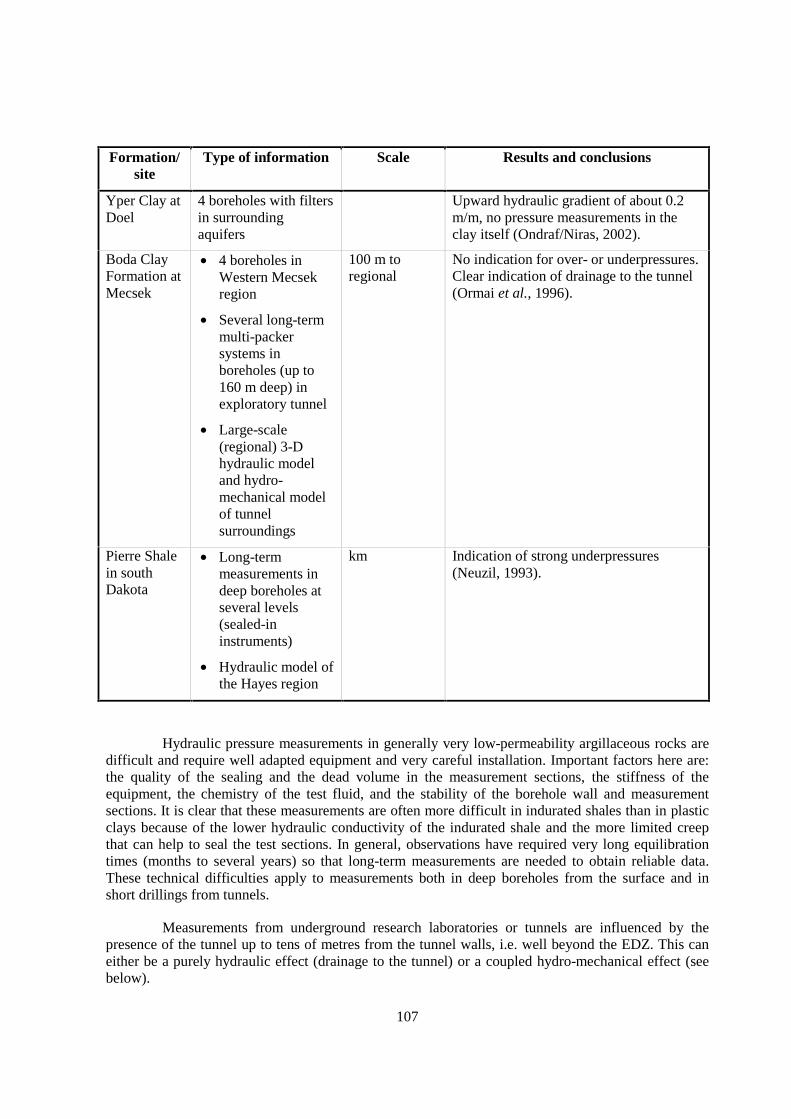
107
Formation/site
Type of information Scale Results and conclusions
Yper Clay atDoel
4 boreholes with filtersin surroundingaquifers
Upward hydraulic gradient of about 0.2m/m, no pressure measurements in theclay itself (Ondraf/Niras, 2002).
Boda ClayFormation atMecsek
• 4 boreholes inWestern Mecsekregion
• Several long-termmulti-packersystems inboreholes (up to160 m deep) inexploratory tunnel
• Large-scale(regional) 3-Dhydraulic modeland hydro-mechanical modelof tunnelsurroundings
100 m toregional
No indication for over- or underpressures.Clear indication of drainage to the tunnel(Ormai et al., 1996).
Pierre Shalein southDakota
• Long-termmeasurements indeep boreholes atseveral levels(sealed-ininstruments)
• Hydraulic model ofthe Hayes region
km Indication of strong underpressures(Neuzil, 1993).
Hydraulic pressure measurements in generally very low-permeability argillaceous rocks aredifficult and require well adapted equipment and very careful installation. Important factors here are:the quality of the sealing and the dead volume in the measurement sections, the stiffness of theequipment, the chemistry of the test fluid, and the stability of the borehole wall and measurementsections. It is clear that these measurements are often more difficult in indurated shales than in plasticclays because of the lower hydraulic conductivity of the indurated shale and the more limited creepthat can help to seal the test sections. In general, observations have required very long equilibrationtimes (months to several years) so that long-term measurements are needed to obtain reliable data.These technical difficulties apply to measurements both in deep boreholes from the surface and inshort drillings from tunnels.
Measurements from underground research laboratories or tunnels are influenced by thepresence of the tunnel up to tens of metres from the tunnel walls, i.e. well beyond the EDZ. This caneither be a purely hydraulic effect (drainage to the tunnel) or a coupled hydro-mechanical effect (seebelow).
108
Measurements of the heads in the surrounding aquifers are needed to allow an interpretationof the observed heads in the argillaceous formation.
In several cases over- or underpressures have been observed with respect to the headsexpected based on the hydraulic boundaries. These could often be explained as consequences ofrelatively fast (geologically speaking) subsidence or uplift-erosion phenomena, by horizontal strainsor, at least in some cases, by osmotic potentials. It has been demonstrated experimentally thatanomalous pressures can be produced in boreholes by osmosis between borehole and formation fluids(see FEP 44).
5.3 Scaling issues
When deep aquifers are considered, the field observations of the hydraulic heads need to bemade at the scale that one needs in the hydrogeological model (e.g. local, regional). This requiresextended piezometric networks and thus a large number of drillings especially for regional scalemodels.
5.4 Scientific level of understanding
At sites where the hydraulic boundary conditions and the burial/deformation history areknown and where sufficiently reliable measurements are available, the level of understanding of thehydraulic potentials is high. In several cases, the measured stable potentials can be explained byhydrogeological modelling (or coupled hydro-mechanical modelling) both in qualitative andquantitative terms (e.g. Ondraf/Niras, 2002, Nagra, 2002).
At sites where only measurements from tunnels are available and where the boundaryconditions are unknown or less clear due to the presence of water-conducting features, theunderstanding of the hydraulic potentials is generally less good. When the effect of the tunnel is onlydrainage, this is well understood and can be successfully included in models. However, when thetunnel induces a coupled hydro-mechanical influence, the quantification is much more difficult.
The transient measured during the equilibration time of the measurements is commonly notwell understood (nor modelled), probably because several coupled processes are acting at the sametime.
The understanding of the processes underlying abnormal formation pressures is limited.While a number of processes can be invoked, their quantification is difficult because relevantparameters are not all well known (e.g. large-scale hydraulic conductivity and its dependence onhydraulic gradient, osmotic efficiency). The most frequently quoted processes to explain abnormalpressures are hydro-mechanical coupling (e.g. compaction due to increased overburden, decompactiondue to erosion or melting of glaciers) and geochemical coupling (osmosis).
5.5 Linked FEPs
FEP 7 Units over- and underlying the host formation: local and regional hydrogeologic framework
FEP 23 Palaeo-hydrogeology of the host formation and of embedding units
FEP 40 Coupled thermo-hydro-mechanic processes
109
FEP 43 Off-diagonal Onsager processes except chemical osmosis
FEP 44 Chemical osmosis
FEP 50 Past burial history
FEP 55 Present-day stress regime
Hydro-mechanical coupling is important in many cases. It can be induced by:
• the drilling of the instrumentation borehole;
• the excavation of the tunnel;
• the subsidence/burial or uplift/erosion (or, more generally, stress) history of the site.
Only the latter is a natural hydraulic non-equilibrium situation. Depending on the hydraulicconductivity of the argillaceous formation and on the duration of the subsidence/burial oruplift/erosion process, this hydraulic non-equilibrium situation can persist many thousands (or evenmillions, see Nagra, 2002) of years. The amplitude of the consequent over- or underpressures alsodepends on the rate of the process.
Geochemical coupling is mentioned by several authors but little information was providedabout the extent to which this effect could influence the measured hydrostatic potentials. Geochemicalcoupling could be an important factor for the length of the equilibration time in experiments,especially when the composition of the test fluid is very different from that of the pore-water.
A study in the Pierre Shale is worth mentioning (Neuzil, 2000). Fluid pressures and soluteconcentrations have been measured in situ for nine years and showed rapid head change (dm to m peryear), which slowed to virtual constancy after 5 to 9 years. The pattern could be quantitativelyinterpreted as an initial pressure change due to chemical osmosis which slowed down as diffusionlowered the concentration gradient (see also FEPs 43 and 44).
Hydro-thermal coupling can also be important, as both the water and the matrix have a lowcompressibility (especially in indurated shales), although only very little information on this wasprovided. In the case of the head evaluation in Opalinus Clay in the Benken borehole, thermal effectswere shown to be irrelevant (Nagra, 2002).
5.6 Level of understanding from a PA perspective and treatment in PA
From a PA perspective, the level of understanding is in general sufficient. Transport in theargillaceous formation is generally dominated by diffusion so that the head distribution in theformation is of relatively low importance. The head distribution in over- and underlying aquifers needsto be known (and can be more easily measured) in order to assess the dilution in those aquifers.Abnormal pressures are taken as evidence of a very low hydraulic conductivity over large scales inspace and time, and thus serve to support the upscaling of measurements in boreholes.
Where sufficient knowledge is available, the hydraulic gradient over the argillaceousformation can be explicitly modelled in PA, and even the potential future evolution of the hydraulicgradient may be considered. However, because diffusion is the dominant transport process, the resultsof PA calculations indicate that the hydraulic gradient is not of high importance.
110
In formations where fracture flow occurs, the knowledge of the regional distribution ofhydraulic potentials is more relevant.
5.7 Available reviews
None reported.
5.8 Planned work
IRSN plans to drill a new borehole penetrating the Toarcian-Domerian at Tournemire in2004. One of the objectives is the characterisation of the head distribution.
5.9 Overall evaluation
This FEP is generally considered as relevant (we received a lot of detailed answers).Although the final influence on the repository performance could be very limited because of thenegligible contribution of advection to transport through low permeability argillaceous formations, thisFEP is very important for the understanding of the local and regional hydrogeological system(including the potential influence of water-conducting features).
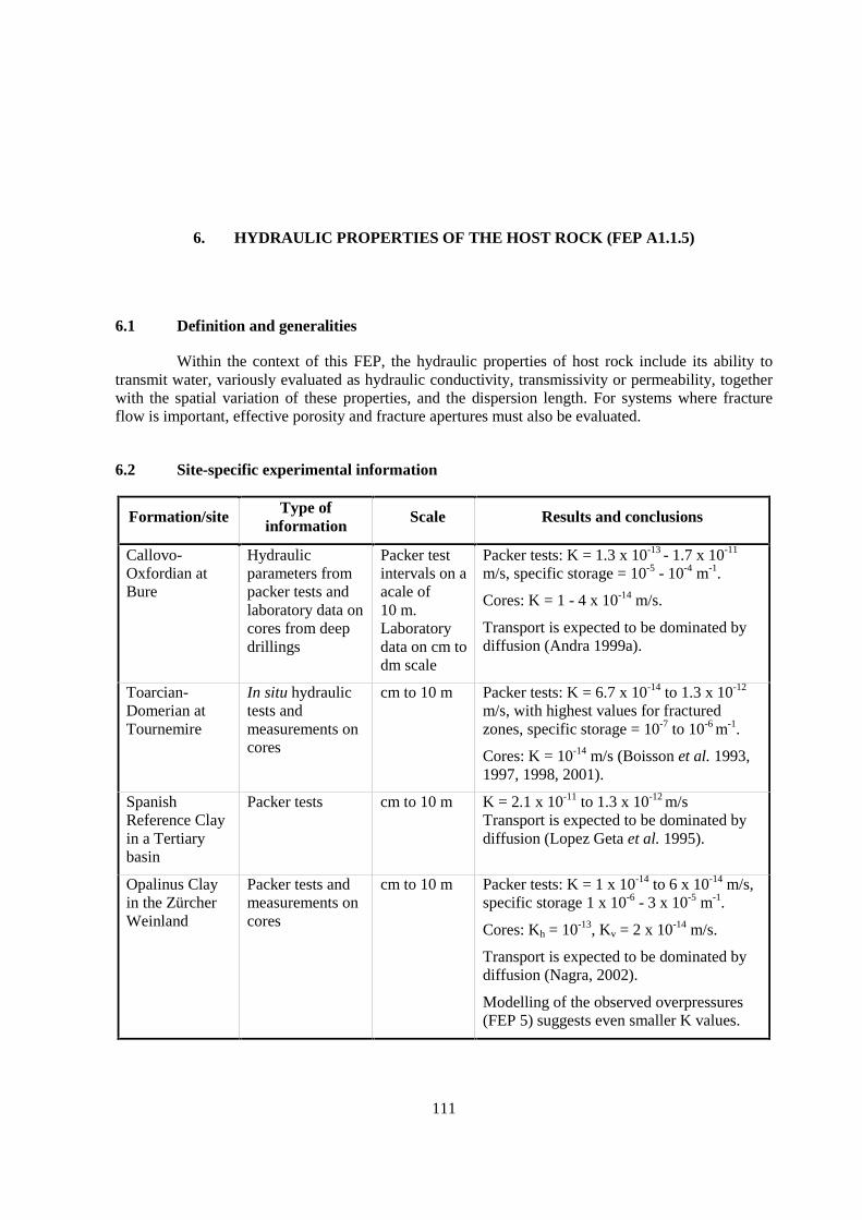
111
6. HYDRAULIC PROPERTIES OF THE HOST ROCK (FEP A1.1.5)
6.1 Definition and generalities
Within the context of this FEP, the hydraulic properties of host rock include its ability totransmit water, variously evaluated as hydraulic conductivity, transmissivity or permeability, togetherwith the spatial variation of these properties, and the dispersion length. For systems where fractureflow is important, effective porosity and fracture apertures must also be evaluated.
6.2 Site-specific experimental information
Formation/site Type ofinformation
Scale Results and conclusions
Callovo-Oxfordian atBure
Hydraulicparameters frompacker tests andlaboratory data oncores from deepdrillings
Packer testintervals on aacale of10 m.Laboratorydata on cm todm scale
Packer tests: K = 1.3 x 10⁻¹³ - 1.7 x 10⁻¹¹
m/s, specific storage = 10-5 - 10-4 m-1.
Cores: K = 1 - 4 x 10-14 m/s.
Transport is expected to be dominated bydiffusion (Andra 1999a).
Toarcian-Domerian atTournemire
In situ hydraulictests andmeasurements oncores
cm to 10 m Packer tests: K = 6.7 x 10⁻¹⁴ to 1.3 x 10⁻¹²
m/s, with highest values for fracturedzones, specific storage = 10-7 to 10-6 m-1.
Cores: K = 10-14 m/s (Boisson et al. 1993,1997, 1998, 2001).
SpanishReference Clayin a Tertiarybasin
Packer tests cm to 10 m K = 2.1 x 10⁻¹¹ to 1.3 x 10⁻¹² m/sTransport is expected to be dominated bydiffusion (Lopez Geta et al. 1995).
Opalinus Clayin the ZürcherWeinland
Packer tests andmeasurements oncores
cm to 10 m Packer tests: K = 1 x 10-14 to 6 x 10-14 m/s,specific storage 1 x 10⁻⁶ - 3 x 10⁻⁵ m-1.
Cores: Kh = 10-13, Kv = 2 x 10-14 m/s.
Transport is expected to be dominated bydiffusion (Nagra, 2002).
Modelling of the observed overpressures(FEP 5) suggests even smaller K values.

112
Formation/site Type ofinformation
Scale Results and conclusions
Opalinus Clayat Mont Terri
In situ hydraulictests andmeasurements oncores
cm to 10 m K = 2 x 10-14 to 1 x 10-12 m/sstorage = 1 to 5 x 10⁻⁶ m-1
(full range: 4 x 10⁻⁷ - 3 x 10⁻⁵ m-1).
Transport is expected to be dominated bydiffusion (Bock, 2001).
Boom Clay atMol
Packer tests,measurements oncores, large-scalesimulation
cm to 10 m K = 10-12 to 10-10 m/s, mean 2.2 x 10⁻¹²
m/s, anisotropy factor about 2, storage0.9 to 1.8 x 10⁻⁵ m-1. Transport is expectedto be dominated by diffusion(Ondraf/Niras, 2002).
Boda ClayFormation atMecsek
Packer tests 10 m K = 1 x 10⁻¹⁰ to 1 x 10-12 m/s, minimum10-13 m/s (fissured zones about a factor100 larger, Ormai et al,. 1996, Csicsak,1996).
Pierre Shale insouth Dakota
Measurements oncores, boreholetests and largescale simulation
cm (cores), 10m (boreholetests), basinscale forsimulations
K= 1 x 10-14 to 1 x 10⁻¹⁰ (values above10-13 m/s influenced by core damage,Neuzil, 1986).
In general very low hydraulic conductivities (i.e. below 10-10 m/s) are measured. Thetechniques to measure such low conductivities both on cores and in boreholes seem to be wellestablished. Measurements in boreholes (packer tests) require high quality boreholes (borehole wallstability is often a problem) and very careful preparation, execution and analysis.
6.3 Scaling issues
Upscaling of hydraulic conductivity of argillaceous formations to the scale of a potentialrepository or to a regional scale is in general difficult. The scale of laboratory measurements is mostlylimited to a few cm3 or dm3. Measurements in boreholes can be done in sections up to the fullthickness of the studied argillaceous formation but the penetration depth into the formation during aninjection test is generally very low (mm to dm). Measurements on the scale of tens of m3 can only bedone in underground research laboratories, e.g. by measuring the water inflow rate in large boreholesor gallery sections, often in combination with the measurement of the hydraulic gradient around theexperimental section. Upscaling is then done by correlating (laboratory or borehole) measurementsfrom different locations with lithology, granulometry and mineralogy.
Values of hydraulic conductivity derived from calibrations of regional scale hydrogeologicalmodels are in some cases larger than those from obtained from measurements (Ondraf/Niras, 2002).The reason for this difference remains currently mostly unexplained.
In Opalinus Clay in the Benken borehole, the observed hydraulic overpressures weremodelled assuming hydro-mechanical coupling (Nagra, 2002). All calculations indicate that large-
113
scale hydraulic conductivities lower than the measured ones are required to explain the preservation ofthe overpressures over long time scales. The preferred hypothesis to explain the scale-dependentvalues is a deviation from Darcy’s law at hydraulic gradients <1, as they occur naturally in theformation. All hydraulic tests, both in situ and in the laboratory, were run with much higher gradients(typically thousands).
In the case of the Pierre Shale, regional permeabilities matched those measured in laboratoryand borehole tests where the formation was at depths greater than about one km. Where the formationis closer to the surface, the regional permeability is 103 higher than values from core and boreholemeasurements. This is attributed to fracture zones separated horizontally by a km or more that areopen near the surface but sealed at depth. (Neuzil & Belitz, 1998).
In formations where fracture flow is important, the upscaling of hydraulic conductivity is nottrivial and depends on the size distribution, density, orientation and heterogeneity of the fractures. Onepossible route for upscaling is the calculation of large-scale effective hydraulic conductivities on thebasis of fracture network models. For example, this approach was taken by Mazurek et al. (1999) forthe highly consolidated and fractured marls at the Wellenberg site in the central Swiss Alps.
6.4 Scientific level of understanding
The hydraulic properties of the argillaceous formations studied are in general wellunderstood at the scale of the measurements. No clear proof of deviations from Darcy’s law have beenfound when measuring hydraulic conductivity, but most of the measurements were performed at muchhigher gradients than those prevailing in the field. The understanding of geochemical andgeomechanical couplings and the role of fractures is in some cases still unsatisfactory. At larger, e.g.regional scale, the scientific level of understanding remains often rather low.
6.5 Linked FEPs
FEP 14 Lithology, mineralogy of rocks and fracture infills
FEP 23 Palaeo-hydrogeology of the host formation and of embedding units
FEP 41 Swelling
FEP 42 Self-sealing
FEP 50 Past burial history
FEP 53 Past deformation events
FEP 54 Future fault (re)activation, changes in migration pathways; changes of hydraulic parameters;flow events
6.6 Level of understanding from a PA perspective and treatment in PA
This FEP is mostly explicitly treated in the PA studies. From a PA perspective, theunderstanding of hydraulic properties is in general satisfactory. As the hydraulic conductivities arevery low, transport, except in open fractures, is dominated by diffusion and so is insensitive to thevalue of hydraulic conductivity, hydraulic gradient as well as to coupled phenomena.

114
In fractured systems where advection is important, upscaling may be difficult and requires agood understanding of fracture geometries and of the connectivity of the fracture network.
6.7 Available reviews
Horseman et al. (1996).
6.8 Planned work
Further research work is planned mainly on upscaling the currently available data anddetermining the potential influence and/or presence of hydraulically conducting faults or fractures.
6.9 Overall evaluation
As argillaceous formations are in general studied because of their favourable hydraulicproperties, i.e. a hydraulic conductivity that is so low that all transport is dominated by diffusion, thisFEP is generally considered as highly relevant. It is mostly fairly well understood and the mainuncertainties are related to geomechanical and geochemical coupling, upscaling and the (potential)role of faults and fractures.
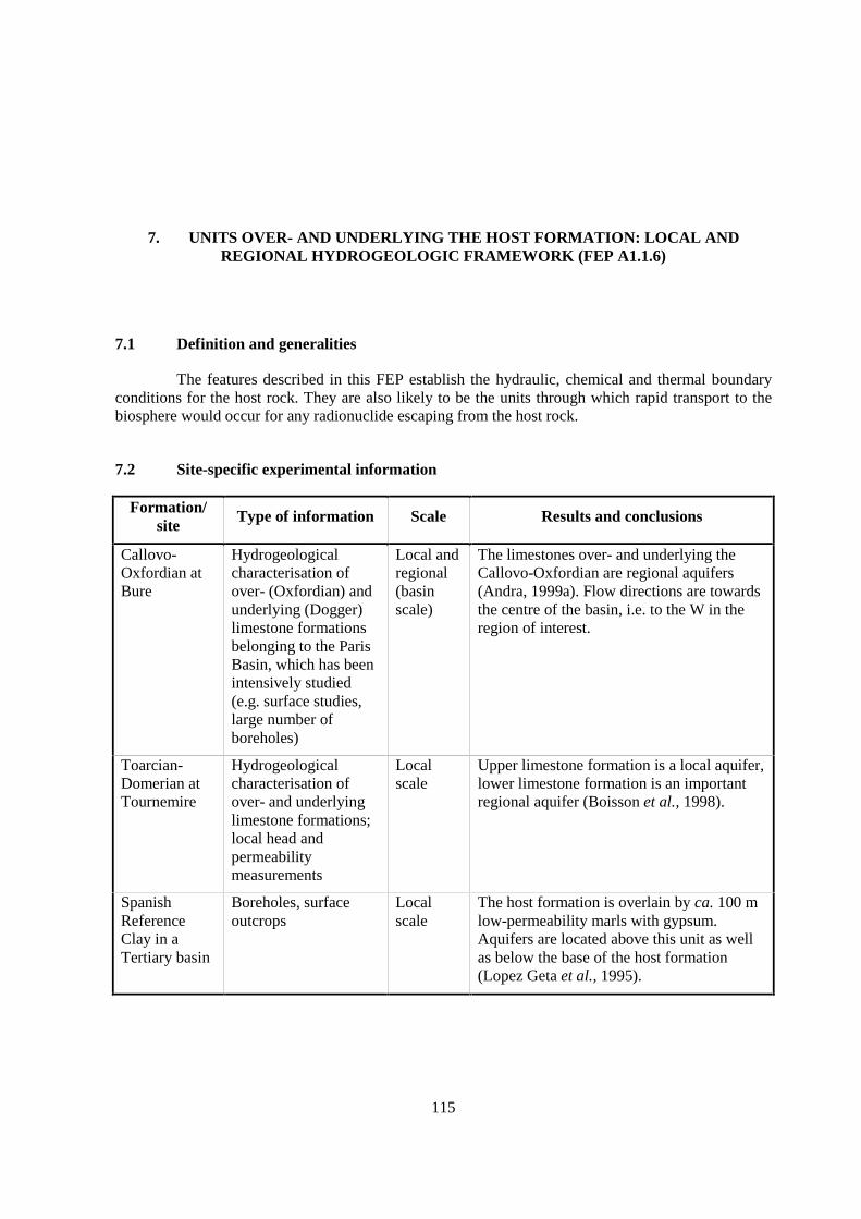
115
7. UNITS OVER- AND UNDERLYING THE HOST FORMATION: LOCAL ANDREGIONAL HYDROGEOLOGIC FRAMEWORK (FEP A1.1.6)
7.1 Definition and generalities
The features described in this FEP establish the hydraulic, chemical and thermal boundaryconditions for the host rock. They are also likely to be the units through which rapid transport to thebiosphere would occur for any radionuclide escaping from the host rock.
7.2 Site-specific experimental information
Formation/site
Type of information Scale Results and conclusions
Callovo-Oxfordian atBure
Hydrogeologicalcharacterisation ofover- (Oxfordian) andunderlying (Dogger)limestone formationsbelonging to the ParisBasin, which has beenintensively studied(e.g. surface studies,large number ofboreholes)
Local andregional(basinscale)
The limestones over- and underlying theCallovo-Oxfordian are regional aquifers(Andra, 1999a). Flow directions are towardsthe centre of the basin, i.e. to the W in theregion of interest.
Toarcian-Domerian atTournemire
Hydrogeologicalcharacterisation ofover- and underlyinglimestone formations;local head andpermeabilitymeasurements
Localscale
Upper limestone formation is a local aquifer,lower limestone formation is an importantregional aquifer (Boisson et al., 1998).
SpanishReferenceClay in aTertiary basin
Boreholes, surfaceoutcrops
Localscale
The host formation is overlain by ca. 100 mlow-permeability marls with gypsum.Aquifers are located above this unit as wellas below the base of the host formation(Lopez Geta et al., 1995).

116
Formation/site
Type of information Scale Results and conclusions
Opalinus Clayat Mont Terri
Pore-watercompositions derivedfrom a series of shortboreholes drilled fromthe safety tunnel(profile across theOpalinus Clay and theembedding units)
Local The Opalinus Clay is overlain by Doggerlimestones and underlain by Liassic marlsand limestones and by Keuper marl andGipskeuper. Pore-water salinity, 18O, 2H andHe contents are greatest at Opalinus Clay-Liassic contact and decrease smoothly to lowvalues in Dogger and Keuper limestoneaquifers.
The distribution of solutes and isotopes onOpalinus Clay and underlying marls isconsistent with diffusion to the overlying andunderlying fresh-water aquifers (Pearson etal., 2003).
Opalinus Clayin the ZürcherWeinland
Boreholes withpermeability and headmeasurements,ground-waterresidence times,hydro-geochemistry,surface outcrops
Local andregional
The host formations (Opalinus Clay +Murchisonae Beds) are embedded withinconfining units, which are dominated byargillaceous, low-permeability formations butcontain potentially water-conducting beds orlocal aquifers. The confining units over- andunderlying the host formations are 100 and150 m thick and are bounded by the regionalaquifers (Malm and Muschelkalk).
The regional aquifers show hydrostaticconditions, whereas slight over- andunderpressures are observed within theconfining units (Nagra, 2002).
Boom Clay atMol
Head measurements,permeability,geochemistry(including isotopes),residence time,hydrogeological modelat different scales
Local(350 km2)up toregional(6 000km2)
The overlying Neogene aquifer is a veryimportant regional aquifer that is heavilyexploited. The underlying units include sandlayers separated by a clay layer (Asseaquitard). These aquifers are more saline, andresidence times show a palaeoclimatic signal(influence of glaciations) Ondraf/Niras,(2002).
Boda ClayFormation atMecsek
Overlying Permiansandstone: headmeasurements,permeability, hydro-geochemistry,hydrogeological model
Localscale
Sandstones form an aquifer (Ormai et al.,1996).
Pierre Shale insouth Dakota
Underlain by regionalDakota Sandstoneaquifer
Regional Distribution of regional verticaltransmissivity of shale deduced from flowmodelling of aquifer (Neuzil & Belitz, 1998).

117
Formation/site
Type of information Scale Results and conclusions
MizunamiGroup at Tono
The overlyingformation is the SetoGroup, anunconsolidated fluvialfacies, the underlyingformation is the Tokibiotite granite;permeability andgeochemical data
The Seto Group is permeable (hydraulicconductivity 10-6 to 10-7 m/s), The Tokigranite has a hydraulic conductivity of 10-9 to10-7 m/s. Reference: Hama et al. (1995).
In most cases the argillaceous formations studied are found in large sedimentary basins andthus fall in a sequence of other geological layers of sedimentary origin (limestones, sandstones, sands,marls...). Each such sequence generally corresponds to a sequence of regional aquifers and aquitards.The aquifers can be rather easily characterised by using classical hydrogeological techniques, provideda sufficient number of observation points is available. Regional hydraulic properties of the targetformation may be inferred from the hydrogeology of bounding aquifers. The geological history andevolution of the target formation may be evident in the patterns of geochemical change through theformation to bounding aquifers.
In most cases, the host formations are located directly between aquifers. In contrast, theOpalinus Clay in the Zürcher Weinland is embedded within low-permeability confining units, whichseparate it from the regional aquifers.
7.3 Scaling issues
Within a sedimentary basin, the geological layers often have a large lateral extent, whichmakes upscaling from local to regional scale relatively easy. For this purpose, in most cases acombination is made of (core) drillings, geophysical logging techniques and seismic investigationsspread over the region of interest.
At least in the case of the Opalinus Clay in the Zürcher Weinland, the situation is morecomplex, and local and regional aquifers have spatially variable properties:
• The overlying Malm is a regional aquifer but has very low hydraulic conductivity in theBenken borehole. A very old (at least hundreds of ka) Na-Cl water was sampled. Thislimestone aquifer is known to be spatially variable due to heterogeneous fracturingand/or degree of karstification.
• The underlying, local aquifer in the Keuper has a high hydraulic conductivity in theBenken borehole, even though the residence time of the water is >25 ka. Lateralvariations of the sedimentary facies (and also of hydraulic properties) are known, and thefindings from the Benken borehole cannot be extrapolated to large horizontal distances(more than a few km).
Depending on regional evidence, the local hydraulic conductivities measured in the Benkenborehole were upscaled and resulted in both higher and lower regional values (Nagra, 2002).
118
7.4 Scientific level of understanding
In general the properties and the behaviour of the over- and underlying units and their rolewithin the regional and local hydrogeological framework are well understood. The main remaininguncertainties are related to the assessment of water fluxes through the aquitards.
7.5 Linked FEPs
FEP 23 Palaeo-hydrogeology of the host formation and of embedding units
FEP 50 Past burial history
FEP 53 Past deformation events
7.6 Level of understanding from a PA perspective and treatment in PA
From a PA perspective, aquifers are considered:
1) to define the hydrogeological and hydrochemical boundary conditions for flow andtransport within the host formations, and
2) as potential exfiltration pathways for radionuclides, where dilution is taken into account.
In general the level of understanding of the local and regional hydrogeological framework issufficient to assess the dilution and radionuclide fluxes that might end up in the aquifer system, as wellas to evaluate the boundary conditions for processes within the host unit.
The local and regional hydrogeological system is explicitly treated in many PA studies. Inmany cases regional 3-D or quasi-3-D hydrogeological models have been applied to simulate theregional ground-water flow and to determine the boundary conditions for local-scale models.Regional-scale models have also been applied to assess the influence of potential climate changes onthe hydrogeological framework. The local-scale models were mainly used to determine the dilutionand fate of radionuclide fluxes that might enter the aquifer system.
In the case of the Opalinus Clay, retention within the confining units which embed the hostformations is neglected in the base case of PA, i.e. direct exfiltration into the aquifers is assumed.Alternative cases calculate the retardation in these units in a simplified way.
7.7 Available reviews
None reported.
7.8 Planned work
None reported.
7.9 Overall evaluation
This FEP is generally well understood both from a scientific and PA perspective. In manycases comprehensive studies have been made on it and the research techniques for it are wellestablished.
119
8. DIFFUSIVITY (FEPS A1.2.1, A2.1.1)
8.1 Definition and generalities
Diffusion occurs in all argillaceous media, both natural clay and shale being considered as apotential host rock, and in plugging and backfill material, particularly compressed bentonite. Diffusionis relevant to the far field in connection with site characterisation and nuclide transport properties forPA and to the affected field as boundary conditions for analysis of the engineered barrier system.
Different definitions of the terms “diffusivity” and “diffusion coefficient” applied tomolecular transport in porous media (rocks) exist in the literature. Special care must be taken withthese definitions when comparing reported rock properties and performing quantitative computationsof diffusive transport.
For describing diffusion in water-saturated porous media, two types of diffusion coefficientsmust be distinguished: the effective diffusion coefficient (De) appropriate for Fick’s first law, and theapparent diffusion coefficient (Da), used with Fick’s second law. Following the definitions ofHorseman et al. (1996), which are widely used:
De = nd (χ/τ2) D0 = nd Dp (1)
where nd is the species-specific diffusion porosity (see FEP 9), D0 the free-water diffusion coefficientappropriate for the species and fluid chemistry of interest, and (χ/τ2) the rock-specific geometry factor.Dp is the rock- and species-specific pore diffusion coefficient.
Da = De / (nd R) = Dp / R (2)
where R is the retardation factor:
R = 1 + (ρd Kd / nd). (3)
ρd is the dry density of the sample and Kd the distribution coefficient of the species (see FEPs 14-22,A2.2 series). For non-retarded species, Da = Dp so Dp may be used in modelling the distribution ofnon-retarded substances.
The term “diffusivity” is variously used to mean, for example:
• Diffusion coefficient, e.g. effective and apparent diffusivities.
• Apparent diffusion coefficient.
• The diffusional tortuosity.
Thus, if the term is used, it should be precisely defined.

120
8.2 Site-specific experimental information
A number of measurements of the diffusion coefficients of argillaceous formations havebeen reported. The following table (based on Nagra, 2002) summarises the results of laboratory testson formations of nuclear-waste interest. These all represent properties of the bulk matrix. No directmeasurements of diffusion properties that cause retardation of solute transport in fractures werereported. Constraints on diffusion coefficients can also be obtained from the quantitative evaluation ofnatural tracer profiles across the host formations, and these aspects are described in FEP 24.
Formation/site Tracer No. of
tests
De parallel (��)or
perpendicular(�) to bedding[x 10-11 m2/s]
Porosity [-] Reference
3H 24 ⊥ 1.4 0.1 - 0.2 Andra (1999a)Callovo-Oxfordian atBure
125I- 5 ⊥ 0.12
Toarcian-Domerian atTournemire
3H
I-
16
4
⊥ 0.4
⊥ 0.02
0.02 - 0.2
-
Boisson et al. (1998),Savoye et al. (2001),Cabrera et al. (2001)
3H ⊥ 10 - 12SpanishReferenceClay in aTertiary basin
Cl- ⊥ 2.9 - 6.8
Tests made onsamples reconstitutedto higher density thanin field
3H 14 ⊥ 1 - 2 0.10 - 0.25Opalinus Clayat Mont Terri
I- 9 ⊥ 0.3 - 0.4 0.06 - 0.15
Nagra (2002)
3H 3 ⊥ 0.5 - 0.7 0.13 - 0.15Opalinus Clayin the ZürcherWeinland
36Cl- 3 ⊥ 0.07 - 0.09 0.03 - 0.04
Nagra (2002)
Boom Clay atMol
3H 4 ⊥ 8 - 11|| ca. twice ⊥
0.46±0.02 at 0.02 M Cl-
0.59±0.07 at 1.0 M Cl-
De Cannière et al.(1996)
I-, Br- 10 ⊥ 2 - 6 Br-: 0.18±0.03 at 0.02 M Cl-
I-: 0.19±0.01 at 0.02 M Cl-
I-: 0.30±0.09 at 1.0 M Cl-
3H 1 ⊥ 0.2 0.03PalfrisFormation atWellenberg I- 1 ⊥ 0.01 0.009
Lineham & Stone(1991), Pearson(1999)
3H, 2H 14 ⊥ 7 - 9 0.56 - 0.62 Bourke et al. (1993)London Clay(UK)
I- 3 ⊥ 3 - 5 0.21 - 0.31
Water 3H 226 Self-diffusion coefficient Atkins (1990)
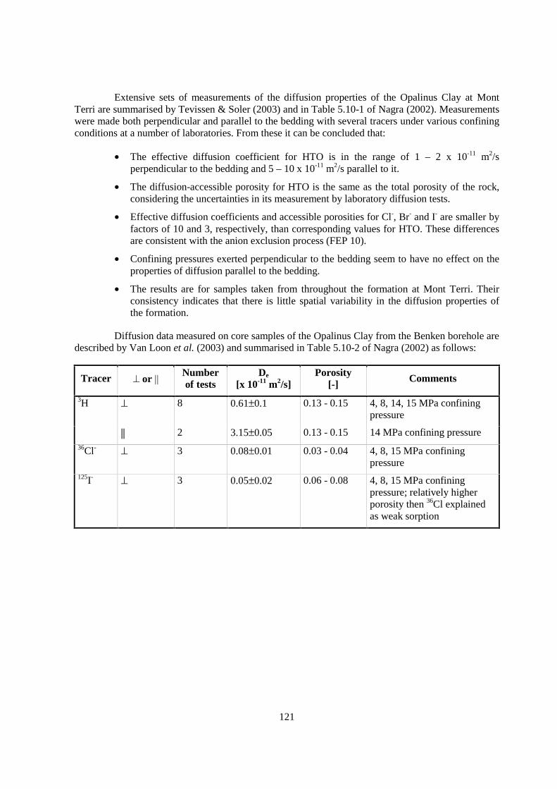
121
Extensive sets of measurements of the diffusion properties of the Opalinus Clay at MontTerri are summarised by Tevissen & Soler (2003) and in Table 5.10-1 of Nagra (2002). Measurementswere made both perpendicular and parallel to the bedding with several tracers under various confiningconditions at a number of laboratories. From these it can be concluded that:
• The effective diffusion coefficient for HTO is in the range of 1 – 2 x 10-11 m2/sperpendicular to the bedding and 5 – 10 x 10-11 m2/s parallel to it.
• The diffusion-accessible porosity for HTO is the same as the total porosity of the rock,considering the uncertainties in its measurement by laboratory diffusion tests.
• Effective diffusion coefficients and accessible porosities for Cl-, Br- and I- are smaller byfactors of 10 and 3, respectively, than corresponding values for HTO. These differencesare consistent with the anion exclusion process (FEP 10).
• Confining pressures exerted perpendicular to the bedding seem to have no effect on theproperties of diffusion parallel to the bedding.
• The results are for samples taken from throughout the formation at Mont Terri. Theirconsistency indicates that there is little spatial variability in the diffusion properties ofthe formation.
Diffusion data measured on core samples of the Opalinus Clay from the Benken borehole aredescribed by Van Loon et al. (2003) and summarised in Table 5.10-2 of Nagra (2002) as follows:
Tracer � or �� Numberof tests
De
[x 10-11 m2/s]Porosity
[-] Comments
3H ⊥ 8 0.61±0.1 0.13 - 0.15 4, 8, 14, 15 MPa confiningpressure
|| 2 3.15±0.05 0.13 - 0.15 14 MPa confining pressure36Cl- ⊥ 3 0.08±0.01 0.03 - 0.04 4, 8, 15 MPa confining
pressure125I- ⊥ 3 0.05±0.02 0.06 - 0.08 4, 8, 15 MPa confining
pressure; relatively higherporosity then 36Cl explainedas weak sorption
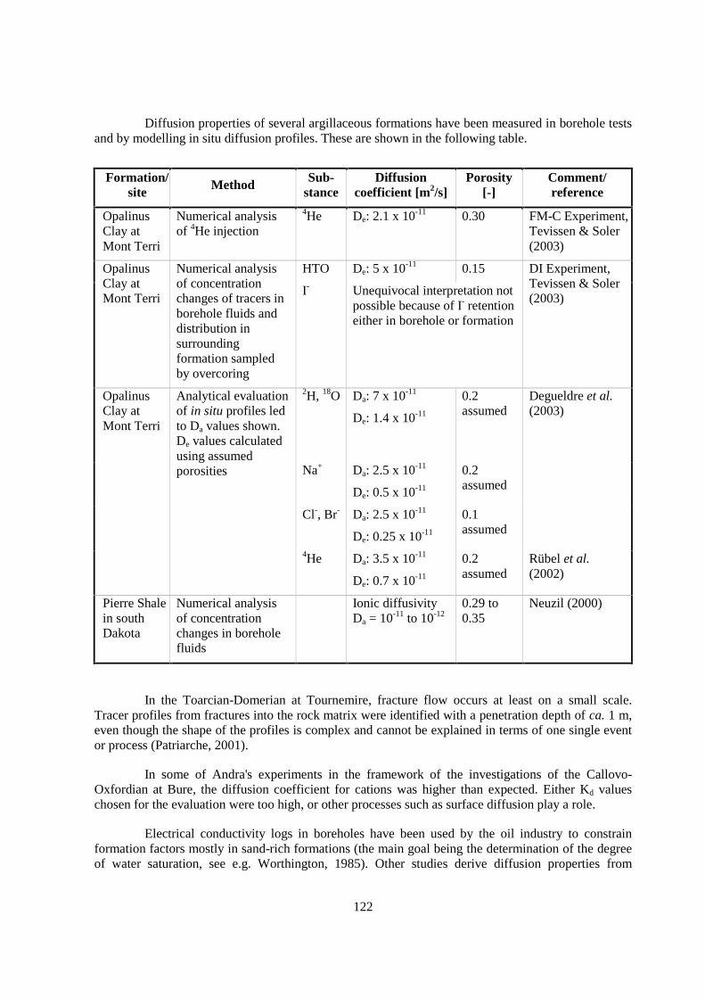
122
Diffusion properties of several argillaceous formations have been measured in borehole testsand by modelling in situ diffusion profiles. These are shown in the following table.
Formation/site Method Sub-
stanceDiffusion
coefficient [m2/s]Porosity
[-]Comment/reference
OpalinusClay atMont Terri
Numerical analysisof 4He injection
4He De: 2.1 x 10⁻¹¹ 0.30 FM-C Experiment,Tevissen & Soler(2003)
HTO De: 5 x 10-11 0.15OpalinusClay atMont Terri
Numerical analysisof concentrationchanges of tracers inborehole fluids anddistribution insurroundingformation sampledby overcoring
I- Unequivocal interpretation notpossible because of I- retentioneither in borehole or formation
DI Experiment,Tevissen & Soler(2003)
OpalinusClay atMont Terri
2H, 18O Da: 7 x 10-11
De: 1.4 x 10⁻¹¹
0.2assumed
Degueldre et al.(2003)
Na+ Da: 2.5 x 10⁻¹¹
De: 0.5 x 10⁻¹¹
0.2assumed
Cl-, Br- Da: 2.5 x 10⁻¹¹
De: 0.25 x 10⁻¹¹
0.1assumed
Analytical evaluationof in situ profiles ledto Da values shown.De values calculatedusing assumedporosities
4He Da: 3.5 x 10⁻¹¹
De: 0.7 x 10⁻¹¹
0.2assumed
Rübel et al.(2002)
Pierre Shalein southDakota
Numerical analysisof concentrationchanges in boreholefluids
Ionic diffusivityDa = 10-11 to 10-12
0.29 to0.35
Neuzil (2000)
In the Toarcian-Domerian at Tournemire, fracture flow occurs at least on a small scale.Tracer profiles from fractures into the rock matrix were identified with a penetration depth of ca. 1 m,even though the shape of the profiles is complex and cannot be explained in terms of one single eventor process (Patriarche, 2001).
In some of Andra's experiments in the framework of the investigations of the Callovo-Oxfordian at Bure, the diffusion coefficient for cations was higher than expected. Either Kd valueschosen for the evaluation were too high, or other processes such as surface diffusion play a role.
Electrical conductivity logs in boreholes have been used by the oil industry to constrainformation factors mostly in sand-rich formations (the main goal being the determination of the degreeof water saturation, see e.g. Worthington, 1985). Other studies derive diffusion properties from
123
measurements of electrical conductivity (e.g. Revil et al,. 1997). All these methods are not specific toclay-rich systems, and it is not clear if the different processes acting in argillaceous rocks can besatisfactorily separated to allow clear conclusions.
8.3 Scaling issues
Most data are based on laboratory tests at cm scales. Field experiments may be possible at mscales, but often not at dam or hm scales required for PA (Put & De Preter, 1997). Only concentrationprofiles of natural tracers are available at those scales. To upscale laboratory data requires informationabout the distribution and homogeneity of diffusion-affecting formation properties, and should betested as far as possible using in situ tests and natural tracers.
In the Opalinus Clay at Mont Terri and in the Benken borehole, the laboratory-deriveddiffusion coefficients are consistent with those calculated for the natural tracer profiles (FEP 24). Inthe Toarcian-Domerian at Tournemire, this is not the case. At other sites, such a comparison has notyet been addressed specifically. While uncertainties exist in the choice of boundary and initialconditions for the quantitative interpretation of large-scale tracer profiles, the constraints are sufficientfor a meaningful result in some cases.
8.4 Scientific level of understanding
The theory of diffusion in homogeneous media is well understood, but the modelling ofdiffusive fluxes in heterogeneous materials with charged surfaces, large surface areas and very smallpores is still not fully resolved. Furthermore, except for solutes of simple chemistry in formationsdemonstrably homogeneous such as the Boom Clay or Opalinus Clay, there are open questions aboutpractical, reliable techniques to choose parameter values for modelling diffusion on the repositoryscale. Knowledge provided by laboratory experiments and field tests is sufficient only for aconstrained extrapolation in space and time. Natural tracer profiles can be used to reduce existinguncertainties.
8.5 Linked FEPs
FEP 9 Connected matrix porosity
FEP 10 Ion exclusion
FEP 11 Surface diffusion
Evaluating the parameters for calculating diffusive flux requires consideration of:
FEPs 14-22 Sorption (A2.2 series).
8.6 Level of understanding from a PA perspective and treatment in PA
Because diffusion is an important transport mechanism in all types of argillaceous rocks, it isusually modelled explicitly for PA. In unfractured rock, diffusion is likely to be the dominant transportmechanism. In some fractured formations, advection in the fractures may dominate, but diffusion intothe matrix will be an important retardation mechanism.

124
Various combinations of parameter values may be required for PA modelling. Da and/or De
values based on laboratory and field experiments may be specified directly for each solute of interest.Alternatively, Dp values along with R or Kd values for each solute may be given. The former arederived from experiments using non-retarded solutes, and the latter are based on considerations givenin FEPs of the A2.2 series (sorption, broad definition). Care must be taken when extrapolatingretardation coefficients calculated using batch Kd values to in situ conditions.
Refinements in modelling, such as variations in diffusion properties with depth, location ordirection, can be included if site data warrant.
8.7 Available reviews
Considerations in diffusion modelling and parameter determination and selection arereviewed by Horseman et al. (1996) and in textbooks on geochemical processes such as those ofLerman (1979) and Lasaga (1998). The classic work on diffusion calculations is that of Crank (1975).
Site specific reviews include those for the Opalinus Clay at Mont Terri by Tevissen & Soler(2003) and for the Opalinus Clay in the Benken borehole, the Mont Terri underground researchlaboratory and for other argillaceous formations in Nagra (2002, Sect. 5.10).
8.8 Planned work
In situ tracer tests and observations of natural tracer concentration patterns are underway orplanned at Mol and Bure.
8.9 Overall evaluation
As the diffusion coefficient is a very sensitive parameter in PA, this FEP is highly relevant.The process is very well understood for non-retarded solutes with simple chemistry, but less so forretarded solutes. Site specific laboratory and field experimental studies will generally be needed toassure that correct values are available for PA. There is particular uncertainty in parameter valuesrequired for modelling retardation of fracture transport by matrix diffusion.

125
9. CONNECTED MATRIX POROSITY (FEPS A1.2.2, A2.1.2)
9.1 Definition and generalities
This FEP applies to all repository concepts that include media rich in clay minerals in thenear or far fields, but explicitly excludes fracture porosity, which is considered in FEP 3. It is relevantto the far field in connection with site characterisation and nuclide transport properties for PA and tothe affected field as boundary conditions for analysis of the engineered barrier system.
Connected matrix porosity is that proportion of the total rock volume that forms continuouspathways through a rock mass allowing possible (albeit possibly perhaps highly tortuous) flow pathsthrough the domain being considered. The distinction between total and interconnected, and betweenmatrix and fracture types of porosity is important for transport calculations in argillaceous formations.The total connected matrix void space will contain some immobile pore-water, i.e. water bound tomineral surfaces and clay-mineral interlayers and non-advecting water in dead-end pore space. Suchwater will not take part in dispersive and advective transport processes, but may be involved indiffusive processes. Hence connected matrix porosity should be differentiated from effective orkinematic porosity, which is the connected porosity involved in advection and dispersion. The currentterminology used to describe various types of porosity is confused and non-standardised. For example,connected porosity (which includes dead-end pore space) is also termed effective porosity by someauthors (e.g. Domenico & Schwartz, 1990), while other authors consider effective and kinematicporosity to exclude dead-end pore space (e.g. Horseman et al., 1996) and hence to represent aproportion of connected porosity. The latter definition is also consistent with the definition of theeffective diffusion coefficient adopted in FEP 8. The types of porosities found in argillaceousformations are discussed by Pearson (1999) using the same definitions as Horseman et al. (1996).These definitions are also adopted in this report.
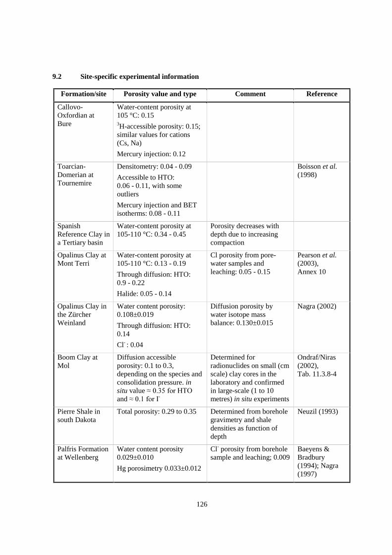
126
9.2 Site-specific experimental information
Formation/site Porosity value and type Comment Reference
Callovo-Oxfordian atBure
Water-content porosity at105 °C: 0.153H-accessible porosity: 0.15;similar values for cations(Cs, Na)
Mercury injection: 0.12
Toarcian-Domerian atTournemire
Densitometry: 0.04 - 0.09
Accessible to HTO:0.06 - 0.11, with someoutliers
Mercury injection and BETisotherms: 0.08 - 0.11
Boisson et al.(1998)
SpanishReference Clay ina Tertiary basin
Water-content porosity at105-110 °C: 0.34 - 0.45
Porosity decreases withdepth due to increasingcompaction
Opalinus Clay atMont Terri
Water-content porosity at105-110 °C: 0.13 - 0.19
Through diffusion: HTO:0.9 - 0.22
Halide: 0.05 - 0.14
Cl porosity from pore-water samples andleaching: 0.05 - 0.15
Pearson et al.(2003),Annex 10
Opalinus Clay inthe ZürcherWeinland
Water content porosity:0.108±0.019
Through diffusion: HTO:0.14
Cl- : 0.04
Diffusion porosity bywater isotope massbalance: 0.130±0.015
Nagra (2002)
Boom Clay atMol
Diffusion accessibleporosity: 0.1 to 0.3,depending on the species andconsolidation pressure. insitu value ������������and ���� �����-
Determined forradionuclides on small (cmscale) clay cores in thelaboratory and confirmedin large-scale (1 to 10metres) in situ experiments
Ondraf/Niras(2002),Tab. 11.3.8-4
Pierre Shale insouth Dakota
Total porosity: 0.29 to 0.35 Determined from boreholegravimetry and shaledensities as function ofdepth
Neuzil (1993)
Palfris Formationat Wellenberg
Water content porosity0.029±0.010
Hg porosimetry 0.033±0.012
Cl- porosity from boreholesample and leaching; 0.009
Baeyens &Bradbury(1994); Nagra(1997)
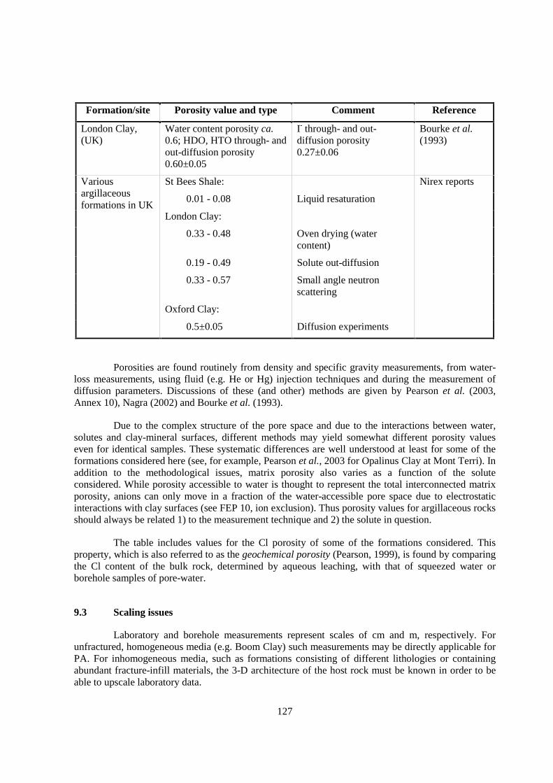
127
Formation/site Porosity value and type Comment Reference
London Clay,(UK)
Water content porosity ca.0.6; HDO, HTO through- andout-diffusion porosity0.60±0.05
I- through- and out-diffusion porosity0.27±0.06
Bourke et al.(1993)
St Bees Shale:
0.01 - 0.08 Liquid resaturation
London Clay:
0.33 - 0.48 Oven drying (watercontent)
0.19 - 0.49 Solute out-diffusion
0.33 - 0.57 Small angle neutronscattering
Variousargillaceousformations in UK
Oxford Clay:
Nirex reports
0.5±0.05 Diffusion experiments
Porosities are found routinely from density and specific gravity measurements, from water-loss measurements, using fluid (e.g. He or Hg) injection techniques and during the measurement ofdiffusion parameters. Discussions of these (and other) methods are given by Pearson et al. (2003,Annex 10), Nagra (2002) and Bourke et al. (1993).
Due to the complex structure of the pore space and due to the interactions between water,solutes and clay-mineral surfaces, different methods may yield somewhat different porosity valueseven for identical samples. These systematic differences are well understood at least for some of theformations considered here (see, for example, Pearson et al., 2003 for Opalinus Clay at Mont Terri). Inaddition to the methodological issues, matrix porosity also varies as a function of the soluteconsidered. While porosity accessible to water is thought to represent the total interconnected matrixporosity, anions can only move in a fraction of the water-accessible pore space due to electrostaticinteractions with clay surfaces (see FEP 10, ion exclusion). Thus porosity values for argillaceous rocksshould always be related 1) to the measurement technique and 2) the solute in question.
The table includes values for the Cl porosity of some of the formations considered. Thisproperty, which is also referred to as the geochemical porosity (Pearson, 1999), is found by comparingthe Cl content of the bulk rock, determined by aqueous leaching, with that of squeezed water orborehole samples of pore-water.
9.3 Scaling issues
Laboratory and borehole measurements represent scales of cm and m, respectively. Forunfractured, homogeneous media (e.g. Boom Clay) such measurements may be directly applicable forPA. For inhomogeneous media, such as formations consisting of different lithologies or containingabundant fracture-infill materials, the 3-D architecture of the host rock must be known in order to beable to upscale laboratory data.
128
Interdependence of porosity and diffusion properties may permit inference of porositydistribution from interpretation of distribution of natural tracers.
9.4 Scientific level of understanding
The concept of porosity is well understood, although practical problems can arise whenconsidering the meaning of different porosity values (e.g. bulk, interconnected, effective, geochemical,etc.) in terms of radionuclide transport, and when interpreting the results of various measurementtechniques. Different porosities are required for different objectives (e.g. advective water flow ordiffusion of a specific solute) and care must be taken to select the one based on the appropriateexperimental technique (see FEP series A1.2 & A2.1).
The correspondence of various methods used to evaluate porosity (e.g. wet vs. dry densities,Hg and gas porosimetry, diffusion techniques, borehole gravimetry, neutron logging, formationfactors) and of the several types of pore-water in argillaceous formations (e.g. interlayer water surface-bound water, unstructured “free” water) with the advective and diffusive transport and geochemicalproperties are much less well understood for argillaceous formations than for coarsely crystalline orcoarse-grained sedimentary rock types.
9.5 Linked FEPs
FEP 14 Lithology, mineralogy of rocks and fracture infills
FEP 17 Pore- and fracture water composition
FEP 18 Dissolution/precipitation of solid phases
FEP 29 Interactions of hyperalkaline fluids and host rock
FEP 33 Thermally induced consolidation of the host rock
FEP 50 Past burial history
FEP 58 Consolidation due to burial
9.6 Level of understanding from a PA perspective and treatment in PA
At a large scale, connected matrix porosity is one of the key parameters governing the diffu-sive and advective transport properties of the host layer. The uncertainty regarding the transfer timethrough the formation is linked to the uncertainty possibly affecting the evaluation of this parameter.
The formative processes (primary and diagenetic) are well understood, leading to areasonable expectation of the degree of spatial variability. The impact of connected porosity onradionuclides relates to both transport and retardation mechanisms. Conceptually, the impact thatconnected matrix porosity has in relation to both components is understood, although detailedproperties such as the sorption for individual species, may not be. Quantitative evaluation of connectedmatrix porosity for transport and retardation experiments is well described for individual samples atthe laboratory scale, but is considered scale dependent. Upscaling requires knowledge of the spatialarrangement of lithologies and fracture-infill materials within heterogeneous formations.
129
In fractured media, the accessibility of the fluid to the adjacent parts of a potential water-conducting structure depends on the connected matrix porosity. Variability of connected matrixporosity, and therefore the diffusion length inside the porous blocks, have an important influence oneffective transit time of the fluid throughout migration pathways.
Diffusion accessible porosity is a key parameter for the calculation of transport in BoomClay. The parameter is sensitive but well understood. For the Boom Clay there is experimentalevidence that the Bruggeman equation (or the more general Ayres equation) is valid (De Cannière etal., 1996). This power law equation relates the effective diffusion constant to the diffusion accessibleporosity.
9.7 Available reviews
The types of porosity found in argillaceous formations are described by Pearson (1999). Thetypes of porosity in the Opalinus Clay and relevant to safety assessment are discussed by Nagra(2002).
9.8 Planned work
None reported.
9.9 Overall evaluation
Diffusion is likely to be a major transport mechanism for release from a repository in anargillaceous host rock. Thus, all parameters relevant to its modelling must be known, including,among others, connected matrix porosity. The uncertainty in determining or estimating connectedmatrix porosity values is likely to be small relative to the uncertainties in values for diffusioncoefficients and concentration gradients that will be used for PA.
Evaluations of connected and effective porosity are important for PA and for sitecharacterisation. The status of conceptual knowledge is adequate, but site specific studies at a varietyof scales are essential. In addition, techniques used to upscale/downscale and investigate retardationmechanisms in relation to interconnected porosity are necessary.
In some PA analyses, neither pore size distributions nor solute-specific accessible porositiesare direct input parameters for PA calculations. Thus, strictly for such PA purposes, it may not benecessary to determine solute-specific accessible porosity. Instead, the effective and apparent diffusioncoefficients (De and Da) could be measured because they are the parameters that really appear in thetransport equations.

131
10. ION EXCLUSION (FEPS A1.2.3, A2.1.4)
10.1 Definition and generalities
The membrane properties of argillaceous rocks are such that ions are excluded to a greaterextent than similarly-sized uncharged solutes. As argillaceous formations are compacted, the doublelayers of adjacent platelets approach and the pore space between them develops a negative charge,which prevents anions from migrating through them. Cations are also restrained by the requirementthat the pore fluid remain electrically neutral. Uncharged solvent and solute molecules are able to passthrough charged pores, but ions are excluded. This process is known as Donnan exclusion (Fritz, 1986;Horseman et al., 1996).
As discussed in FEP 17, the geochemical, or free-water, porosity is required to find thesalinity of pore-water from bulk leaching data when the water cannot be sampled directly. Theporosity from which ions are not excluded corresponds to its geochemical or free-water porosity(Pearson 1999). The extent to which ions are excluded increases with compaction. It decreases withthe salinity of the pore-water because the thickness of the double layer decreases as salinity increases.
Ion exclusion affects a number of diagonal and off-diagonal Onsager transport processes,such as diffusion, chemical osmosis or hyperfiltration (FEPs 8, 43, 44).
10.2 Site-specific experimental information
Several types of studies of the membrane properties of argillaceous rocks have been carriedout that are relevant to nuclear waste site characterisation and PA.
Laboratory studies of diffusion in a number of argillaceous rocks are described in FEP 8.Comparison of the effective diffusion coefficients from these studies shows the extent to which ionswill be excluded relative to other ions during diffusion.
Laboratory and field studies of osmosis in samples of Opalinus Clay from Mont Terri, andborehole studies in the Pierre Shale are described in FEP 44. These provide data on osmoticefficiencies that can be used to evaluate ion exclusion associated with advection.
Finally, one study of hyperfiltration of uncharged solutes is also under way. Natural organicsthat can affect nuclide transport are found in the pore-water of the Boom Clay (FEP 17). Thechemistry of the Boom Clay pore-water shows that the formation has been flushed by fresh water, yetthe organics remain. Studies of Boom Clay core are now in progress testing the hypothesis that thisretention of organics is a result of hyperfiltration or possibly ion exclusion.

132
10.3 Scaling issues
The theory of diffuse double layers applies at the microscopic scale. Effective diffusioncoefficients and diffusion porosities are based on laboratory studies carried out at the scale ofcentimetres. The scale relevant for PA is several tens of metres. In homogenous rock, no significantscale effects are to be expected. Nevertheless, the validity of upscaling has to be verified by in situtests, such as studies of natural tracer concentration profiles of chloride and bromide and by precisecharacterisation of lithologic variability.
10.4 Scientific level of understanding
Although ion exclusion is well-known in principle, the effect of salinity variations on diffu-sion, and a description of anionic exclusion at a microscopic level is needed.
The formation of diffuse double layers with a deficiency of negative charge (deficiency inanion concentration) and an excess of positive charge (excess cation concentration) has a goodtheoretical basis (e.g. Sposito, 1984). The former provides good qualitative understanding of themacroscopic effect of anionic exclusion on diffusion. Cation exclusion is explained as the result ofelectrostatic coupling between cations and anions in order that positive and negative charges will bebalanced during transport. However, it is not clear that this restriction applies to transport of a tracer,which could occur by an exchange mechanism (e.g., diffusion of K+ in an argillaceous formationcontaining an NaCl pore-water).
10.5 Linked FEPs
FEP 9 Connected matrix porosity
FEP 14 Lithology, mineralogy of rocks and fracture infills
FEP 17 Pore- and fracture-water composition
FEP 29 Interactions of hyperalkaline fluids and host rock
10.6 Level of understanding from a PA perspective and treatment in PA
In unfractured argillaceous formations, diffusion is the dominant transport mechanism. Inmodels used directly for PA, effective and/or apparent diffusion coefficients are used directly. Valuesfor these coefficients are commonly laboratory values, but field experiments and natural tracer studiesmay also provide quantitative information. Ion exclusion information and ion-specific diffusionporosities are used to calculate pore diffusion coefficients which are used in some PA calculations. Inaddition, they are used to support estimates of diffusion coefficients for unmeasured species and, asgeochemical porosities, to support the calculation of pore-water salinity and chemistry in formationstoo tight for direct sampling.
10.7 Available reviews
Horseman et al. (1996), Soler (1999, 2001).

133
10.8 Planned work
None reported.
10.9 Overall evaluation
Ion exclusion results in differences in the porosity accessible for transport of solutes ofvarious charges and sizes. It is important in describing diffusive transport, in the membrane and os-motic properties of argillaceous rocks and in quantifying the pore-water chemistry. Diffusion-accessible porosities may be used directly in PA transport calculations as necessary support forchoosing PA diffusion parameter values.

135
11. SURFACE DIFFUSION (FEPS A1.2.4, A2.1.5)
11.1 Definition and generalities
Diffusion rates and apparent diffusion coefficients (Da) measured for sorbing cations such asCs+ and Sr+2 in compacted bentonite may be higher than values calculated using batch distributioncoefficient (Kd) values (see FEP 8, eq. 2 & 3). The difference has been explained either by arguing thatdistribution coefficients in the compacted bentonite are smaller than those measured in batchexperiments, or by proposing the existence of an additional transport mechanism. The latter process,surface diffusion, postulates that a fraction of the cations close to the clay-mineral surfaces are stillmobile (able to move along the surfaces), and contribute to the total diffusive flux of cations.
Surface diffusion may be relevant to the far field in connection with site characterisation andnuclide transport properties for PA and to the affected field as boundary conditions for analysis of theengineered barrier system.
It could also be the case that values for the pore diffusion coefficient (Dp) or porosity (n)used to calculate the expected diffusion properties are incorrect. The values used are usually thosemeasured using non-retarded anions or water isotope tracers (HDO, HTO), and could well beinappropriate for calculating cation properties. Certainly, anion porosities are smaller than those forwater itself (FEP 9).
If surface diffusion does occur, the measured effective (Dem) and apparent (Dam) diffusioncoefficients can be considered to include pore diffusion (Dp) and surface diffusion (Ds) contributionsacting in parallel so they can be summed (Horseman et al. 1996, Lehikoinen 1999):
Dem = n Dp + (1 – n) ρd Kd Ds (1)
can be combined with the retardation factor R = 1+ρdKd
n to obtain
Dam =Dem
n R=
n Dp + (1 − n) ρd Kd Ds
n + ρd Kd. (2)
This formulation assumes that surface diffusion is uniform across the part of the cross-section of the clay which is occupied by minerals. The surface diffusion coefficient (Ds) is thus anaveraged parameter of no fundamental significance.
The proposed mechanism of surface diffusion has not been well described. It seems unlikelythat the phenomenon observed involves movement of ions or molecules that are chemically bound tomineral surfaces by surface complexation or ion exchange. A more plausible explanation would bethat cations which can take part in an ion exchange process are not “sorbed” at specific sites at themineral surface. Instead, they may be those that occupy the diffuse layer in the vicinity of the surface
136
and, thus, are still mobile. The ion mobility in this layer may be lower than in ordinary water becauseof the higher viscosity of the water layer adjacent to the clay-mineral surface.
Horseman et al. (1996) conclude that discrepancies between measured and calculated diffu-sion properties can be explained as the result of using inapplicable parameter values for calculating theexpected properties. Thus, they see no need to invoke surface diffusion as a process of real concern. Insupport of this conclusion, they cite Oscarson (1994) who concluded that batch-measured distributioncoefficients may be too high and lead to calculated diffusion coefficients lower than those measured indiffusion experiments.
11.2 Site-specific experimental information
Effects interpreted as surface diffusion in argillaceous media have been observed incompressed bentonite. However, recent laboratory work on samples from the Callovo-Oxfordian atBure and from the Opalinus Clay in Benken indicate that effective diffusion coefficients for Na exceedthose of HTO (Andra 1999 and work in progress at Paul Scherrer Institut, Switzerland).
11.3 Scaling issues
None, because of lack of definition and understanding of process.
11.4 Scientific level of understanding
The level of understanding is poor. The process is invoked to explain differences betweenmeasured and predicted diffusion behaviour of cations in compressed bentonite and a small number ofargillaceous rocks. The differences may have other causes so that surface diffusion may not actuallyoccur.
11.5 Linked FEPs
FEP 8 Diffusivity
FEP 9 Connected matrix porosity
In addition, sorption properties and the characteristics of double layers considered in theA2.2 series of FEPs are important in evaluating causes for and explanations of surface diffusion.
11.6 Level of understanding from a PA perspective and treatment in PA
Surface diffusion is not explicitly included in PA models. If directly measured diffusionproperties (Da, np) are used for PA, the effects of surface diffusion, whether it exists on not, will beincluded. (See FEP 8).
11.7 Available reviews
Horseman et al., 1996; Lehikoinen, 1999.

137
11.8 Planned work
None reported.
11.9 Overall evaluation
Understanding of surface diffusion is quite limited, and the process may not occur at all.Most available data refer to compacted bentonite rather than to argillaceous formations, and results arecontradictory. The need to invoke surface diffusion can be avoided by using site- and solute-specificdiffusion parameters measured by through-diffusion on samples with their in situ fabric.

139
12. COLLOID FORMATION, TRANSPORT AND FILTRATION (FEP A1.3)
12.1 Definition and generalities
Colloids are very fine and well dispersed particles that, in a hydrogeochemical environment,can contribute to the transport of contaminants. Particles of clay minerals, silica, iron oxy-hydroxides,other minerals, organic and bio-organic macromolecules may form the colloid phase. From a sizedistribution point of view, colloids are defined (IUPAC) as particles with sizes ranging from 1 to1000 nm.
12.2 Site-specific experimental information
Formation/site Results and conclusions
Opalinus Clayat Mont Terri
Colloids were studied is several water samples collected in situ (Degueldre et al.,1998). Investigations were focussed to the size range 1-10 nm because only suchsmall colloids are potentially mobile in the pore space, and a concentration of10-20 ppt was derived. Humic colloids are below detection limit.
Opalinus Clayin the ZürcherWeinland
Possible colloids include clay minerals, quartz, calcite, Fe hydroxides andorganics, even though their stability under in situ-conditions is limited. Mobilityof colloids is very low due to the very low permeability and nanometre-scalepore structure of Opalinus Clay. Model calculations indicate that colloid-relatedtransport is negligible (Voegelin & Kretzschmar, 2001).
The role of organic colloids in Opalinus Clay is not thoroughly studied.Laboratory experiments indicate that the sorption characteristics of nickel,europium and thorium are independent of the presence or absence of organiccolloids (Glaus et al., 2001).
Boom Clay atMol
Boom Clay acts as an ultrafilter, therefore mobile colloids should only be presentin very low concentrations (Ondraf/Niras, 2002).
Only very few studies are available. Colloids that are potentially mobile in the studiedargillaceous formations were only found in extremely low concentrations. In many cases, colloidtransport is considered irrelevant, at least in cases where fracture flow is not important.
12.3 Scaling issues
None reported.
140
12.4 Scientific level of understanding
See Section II, Chapter 12.6.
12.5 Linked FEPs
FEP 3 Migration pathways, including heterogeneity and anatomy
FEP 9 Connected matrix porosity
FEP 15 Natural organics, complexation.
FEP 17 Pore- and fracture water composition
FEP 18 Dissolution / precipitation of solid phases
FEP 20 Ion exchange
FEP 21 Surface complexation
FEP 30 Organics from waste and their effect on transport properties of the host rock
12.6 Level of understanding from a PA perspective and treatment in PA
Colloids, especially in argillaceous systems, are difficult to study. Only very few studieshave been performed concerning the behaviour of colloids in argillaceous formations, so the level ofscientific understanding is rather low. Actinides are known to form colloids or to associate withcolloids. While tetravalent actinides tend to form inorganic colloids, trivalent actinides mainlyassociate with organic colloids. However, many argillaceous formations are considered to be efficientcolloid filters, and colloid-facilitated transport in unfractured media is regarded to be of limitedimportance. Open points exist in the case of fracture-dominated transport, either in natural fracturesystems or in the EDZ.
The effect of colloids on transport in argillaceous formations is regarded as negligible inmost PA studies. Conservative estimates can be made by considering a retardation factor R=1 forpotentially complexed radionuclides.
12.7 Available reviews
Summary of a working group at NEA’s GEOTRAP workshop 2001: Hadermann (2002).
12.8 Planned work
None reported.
12.9 Overall evaluation
This FEP is in general considered not important for unfractured argillaceous formations. Itmay have some importance in systems with fracture flow.

141
13. FLOW-WETTED SURFACE AND ACCESSIBILITY OF MATRIX (FEP A2.1.3)
13.1 Definition and generalities
This FEP is of importance mainly in the case of over-consolidated, fractured argillaceousformations. Flow-wetted surface is the surface area per unit rock volume of the walls of fractureswhere advection takes place. Matrix accessibility refers to the extent to which the rock matrix isaccessible by diffusion to solutes migrating through fractures. If fractures, particularly the walls, aremineralised, the accessibility of the rock matrix may be reduced.
13.2 Site-specific experimental information
The most highly indurated sites considered, the Palfris Formation at Wellenberg(Switzerland) and the Boda Clay Formation (Hungary), contain fracture minerals (mostly carbonates),whose distribution is heterogeneous. Permeable structures were observed mainly along the contactsbetween fracture infill and wall rock, i.e. flowing water is in direct contact with the wall-rock porosityat least at one side. Moreover, even the fracture infills were shown to have a diffusion-accessibleporosity (Nagra, 1997).
At the Wellenberg site, only a fraction of all faults penetrated by the boreholes havetransmissivity measurable above the detection limit of ca. 10-9 m2/s. It was concluded thattransmissivity is distributed heterogeneously within each fault (Mazurek et al., 1999), and thepossibility exists that not all parts of the fracture surfaces are accessible to flow, which in turn reducesflow-wetted surface.
In the Boda Clay Formation, geological and geochemical indications for water-rockinteractions, including mineralogical and isotopic analyses, were investigated in order to identify thelocations of past water-flow events (Arkai et al., 2000). Some degree of heterogeneity was observed inthe spatial distribution of fracture infills and of the degree of wall-rock alteration (e.g. formation ofsmectite at the expense of chlorite), indicating that water flow at the time when the water-rockinteraction occurred was not distributed evenly, leaving parts of the fractures unaffected.
13.3 Scaling issues
Relevant observations on scales of mm to dm can be made in surface outcrops, tunnels andcore materials. This scale is the same as the one required for the conceptualisation of migrationpathways for transport calculations.
142
13.4 Scientific level of understanding
Indications exist that the distribution of flow in faults and fractures in indurated shaleformations is heterogeneous. Therefore, flow-wetted surface may be smaller than the total area offracture walls per unit volume. Data and approaches pertinent to fractured argillaceous systems arelimited at present. Approaches to estimate and conceptualise flow-wetted surface are well developedin PA programmes targeted at crystalline rocks, e.g. in Sweden or in Finland.
13.5 Linked FEPs
FEP 1 Advection/dispersion
FEP 3 Migration pathways, including heterogeneity and anatomy
FEP 16 Mineral-surface area
FEP 18 Dissolution / precipitation of solid phases
FEP 29 Interactions of hyperalkaline fluids and host rock
FEP 41 Swelling
FEP 42 Self-sealing
FEP 53 Past deformation events
FEP 54 Future fault (re)activation, changes in migration pathways; changes of hydraulic parameters;flow events
13.6 Level of understanding from a PA perspective and treatment in PA
This FEP is important only in highly indurated formations where fracture flow dominates.The only example of PA treatment comes from the Palfris Formation at Wellenberg (Switzerland),where flow-wetted surface was derived directly from cm- to dm-scale geometric conceptual models ofthe migration pathways (Nagra, 1997).
13.7 Available reviews
None reported.
13.8 Planned work
None reported.
13.9 Overall evaluation
Flow-wetted surface is a parameter related exclusively to indurated shale formations wherefracture flow is important. It is of no concern in diffusion-dominated systems. There are no indicationsof limited matrix accessibility. Fracture infills themselves are porous, and in general at least one sideof a fracture is in direct contact with the rock matrix.
Heterogeneity of fractures may result in a reduction of flow-wetted surface. Given the factthat matrix diffusion in argillaceous formations can be regarded as unlimited, large matrix volumes ofrock can be accessed by diffusion even if the areas of contact with flowing water are limited.
143
14. LITHOLOGY, MINERALOGY OF ROCKS AND FRACTURE INFILLS (FEP A2.2.1)
14.1 Definition and generalities
Lithology and mineralogy of rocks and fracture infills affect the hydrogeological, chemicaltransport, geomechanical and other properties of the formation. The electro-chemical behaviour ofminerals is of prime importance for sorption processes. Mineralogy also determines the chemistry ofthe ground water through a range of bulk water-rock interaction processes and related mechanismssuch as osmotic processes, diffusion and matrix diffusion.
The occurrence of fractures may differ from one type of argillaceous formation to another. Inwell-consolidated shales, fractures are common and they are often filled with secondary minerals. Incontrast, in plastic clays, fractures are less common and contain less or no infill material.
144
14.2 Site-specific experimental information
Formation/site
Type ofinformation Results and conclusions
Callovo-Oxfordianat Bure
Deep boreholes,geophysical logs,2-D seismics, 3-D seismicsurvey, logsfrom petroleumdrillings in theregion
The host rock consists of three sedimentary sequences, whichcorrespond to marine depositional cycles and result in differentlithologic facies (from bottom to top):
• 555-520 m below surface: 35 m thick homogeneous siltyshales (C2a facies) of Callovian age, directly overlying Doggercarbonates.
• 520-440 m below surface (Oxfordian):
a. 45 m thick, homogeneous shaly member (C2b1 facies),starting with a six metres thick layer including fivedecimetric sections of shaly limestones. The clay-mineralcontent progressively increases to 50 - 60% up to 495 mdepth and stays high until 475 m below surface.
b. 16 m thick sequence of silty and carbonaceous shales(C2b2 facies) showing a smooth decrease of clay-mineralcontent.
c. 19 m thick sequence of shaly, carbonaceous siltstone(C2c facies), showing a major a decrease of clay-mineralcontent and an increase of quartz and carbonates at the topof the interval.
• 440 to 422 m below surface: 18 metre thick sequence ofcarbonaceous silt of Oxfordian age (silty and dolomiticbiomicrite - biosparite. Clay-mineral content progressivelyincreases to the top. The top of this lithologic facies, alsohighlighted by a distinct level in many geophysical logs, isconsidered as the top of the host formation.
On the average, the Callovo-Oxfordian shales contain 40 to 45%clay minerals. An interstratified illite-smectite phase is the mostabundant clay mineral, with the “R1” type (60 to 75% of illite inthe mixed-layer phase) in the lower part and the “R0” type (40 to60% of illite) in the upper part. The progression from “R1” to “R0”takes place in a 10 m thick interval at around 495 m below surface.
To date, no fractures have been identified in the host rock.
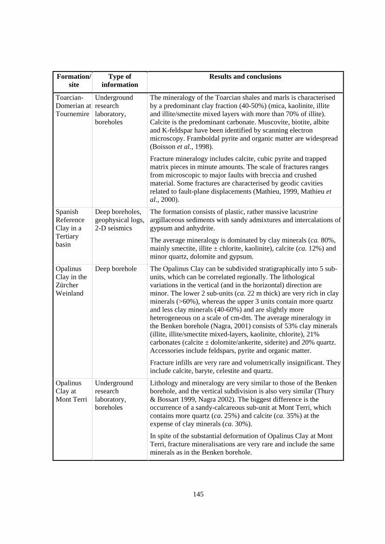
145
Formation/site
Type ofinformation
Results and conclusions
Toarcian-Domerian atTournemire
Undergroundresearchlaboratory,boreholes
The mineralogy of the Toarcian shales and marls is characterisedby a predominant clay fraction (40-50%) (mica, kaolinite, illiteand illite/smectite mixed layers with more than 70% of illite).Calcite is the predominant carbonate. Muscovite, biotite, albiteand K-feldspar have been identified by scanning electronmicroscopy. Framboïdal pyrite and organic matter are widespread(Boisson et al., 1998).
Fracture mineralogy includes calcite, cubic pyrite and trappedmatrix pieces in minute amounts. The scale of fractures rangesfrom microscopic to major faults with breccia and crushedmaterial. Some fractures are characterised by geodic cavitiesrelated to fault-plane displacements (Mathieu, 1999, Mathieu etal., 2000).
SpanishReferenceClay in aTertiarybasin
Deep boreholes,geophysical logs,2-D seismics
The formation consists of plastic, rather massive lacustrineargillaceous sediments with sandy admixtures and intercalations ofgypsum and anhydrite.
The average mineralogy is dominated by clay minerals (ca. 80%,mainly smectite, illite ± chlorite, kaolinite), calcite (ca. 12%) andminor quartz, dolomite and gypsum.
OpalinusClay in theZürcherWeinland
Deep borehole The Opalinus Clay can be subdivided stratigraphically into 5 sub-units, which can be correlated regionally. The lithologicalvariations in the vertical (and in the horizontal) direction areminor. The lower 2 sub-units (ca. 22 m thick) are very rich in clayminerals (>60%), whereas the upper 3 units contain more quartzand less clay minerals (40-60%) and are slightly moreheterogeneous on a scale of cm-dm. The average mineralogy inthe Benken borehole (Nagra, 2001) consists of 53% clay minerals(illite, illite/smectite mixed-layers, kaolinite, chlorite), 21%carbonates (calcite ± dolomite/ankerite, siderite) and 20% quartz.Accessories include feldspars, pyrite and organic matter.
Fracture infills are very rare and volumetrically insignificant. Theyinclude calcite, baryte, celestite and quartz.
OpalinusClay atMont Terri
Undergroundresearchlaboratory,boreholes
Lithology and mineralogy are very similar to those of the Benkenborehole, and the vertical subdivision is also very similar (Thury& Bossart 1999, Nagra 2002). The biggest difference is theoccurrence of a sandy-calcareous sub-unit at Mont Terri, whichcontains more quartz (ca. 25%) and calcite (ca. 35%) at theexpense of clay minerals (ca. 30%).
In spite of the substantial deformation of Opalinus Clay at MontTerri, fracture mineralisations are very rare and include the sameminerals as in the Benken borehole.
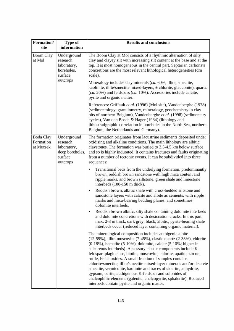
146
Formation/site
Type ofinformation
Results and conclusions
Boom Clayat Mol
Undergroundresearchlaboratory,boreholes,surfaceoutcrops
The Boom Clay at Mol consists of a rhythmic alternation of siltyclay and clayey silt with increasing silt content at the base and at thetop. It is most homogeneous in the central part. Septarian carbonateconcretions are the most relevant lithological heterogeneities (dmscale).
Mineralogy includes clay minerals (ca. 60%, illite, smectite,kaolinite, illite/smectite mixed-layers, ± chlorite, glauconite), quartz(ca. 20%) and feldspars (ca. 10%). Accessories include calcite,pyrite and organic matter.
References: Griffault et al. (1996) (Mol site), Vandenberghe (1978)(sedimentology, granulometry, mineralogy, geochemistry in claypits of northern Belgium), Vandenberghe et al. (1998) (sedimentarycycles), Van den Bosch & Hager (1984) (lithology andlithostratigraphic correlation in boreholes in the North Sea, northernBelgium, the Netherlands and Germany).
Boda ClayFormationat Mecsek
Undergroundresearchlaboratory,deep boreholes,surfaceoutcrops
The formation originates from lacustrine sediments deposited underoxidising and alkaline conditions. The main lithology are albiticclaystones. The formation was buried to 3.5-4.5 km below surfaceand so is highly indurated. It contains fractures and faults originatingfrom a number of tectonic events. It can be subdivided into threesequences:
• Transitional beds from the underlying formation, predominantlybrown, reddish brown sandstone with high mica content andripple marks, and brown siltstone, green shale and limestoneinterbeds (100-150 m thick).
• Reddish brown, albitic shale with cross-bedded siltstone andsandstone layers with calcite and albite as cements, with ripplemarks and mica-bearing bedding planes, and sometimesdolomite interbeds.
• Reddish brown albitic, silty shale containing dolomite interbedsand dolomite concretions with desiccation cracks. In this partmax. 2-3 m thick, dark grey, black, albitic, pyrite-bearing shaleinterbeds occur (reduced layer containing organic material).
The mineralogical composition includes authigenic albite(12-59%), illite-muscovite (7-45%), clastic quartz (2-33%), chlorite(0-18%), hematite (5-10%), dolomite, calcite (5-10%; higher incalcareous interbeds). Accessory clastic components include K-feldspar, plagioclase, biotite, muscovite, chlorite, apatite, zircon,rutile, Fe-Ti oxides. A small fraction of samples containschlorite/smectite, illite/smectite mixed-layer minerals and/or discretesmectite, vermiculite, kaolinite and traces of siderite, anhydrite,gypsum, barite, authigenous K-feldspar and sulphides ofchalcophilic elements (galenite, chalcopyrite, sphalerite). Reducedinterbeds contain pyrite and organic matter.
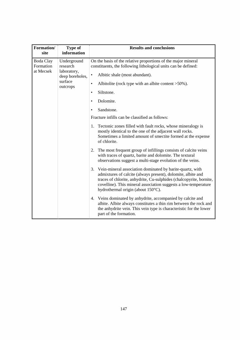
147
Formation/site
Type ofinformation
Results and conclusions
Boda ClayFormationat Mecsek
Undergroundresearchlaboratory,deep boreholes,surfaceoutcrops
On the basis of the relative proportions of the major mineralconstituents, the following lithological units can be defined:
• Albitic shale (most abundant).
• Albitolite (rock type with an albite content >50%).
• Siltstone.
• Dolomite.
• Sandstone.
Fracture infills can be classified as follows:
1. Tectonic zones filled with fault rocks, whose mineralogy ismostly identical to the one of the adjacent wall rocks.Sometimes a limited amount of smectite formed at the expenseof chlorite.
2. The most frequent group of infillings consists of calcite veinswith traces of quartz, barite and dolomite. The texturalobservations suggest a multi-stage evolution of the veins.
3. Vein-mineral association dominated by barite-quartz, withadmixtures of calcite (always present), dolomite, albite andtraces of chlorite, anhydrite, Cu-sulphides (chalcopyrite, bornite,covelline). This mineral association suggests a low-temperaturehydrothermal origin (about 150°C).
4. Veins dominated by anhydrite, accompanied by calcite andalbite. Albite always constitutes a thin rim between the rock andthe anhydrite vein. This vein type is characteristic for the lowerpart of the formation.
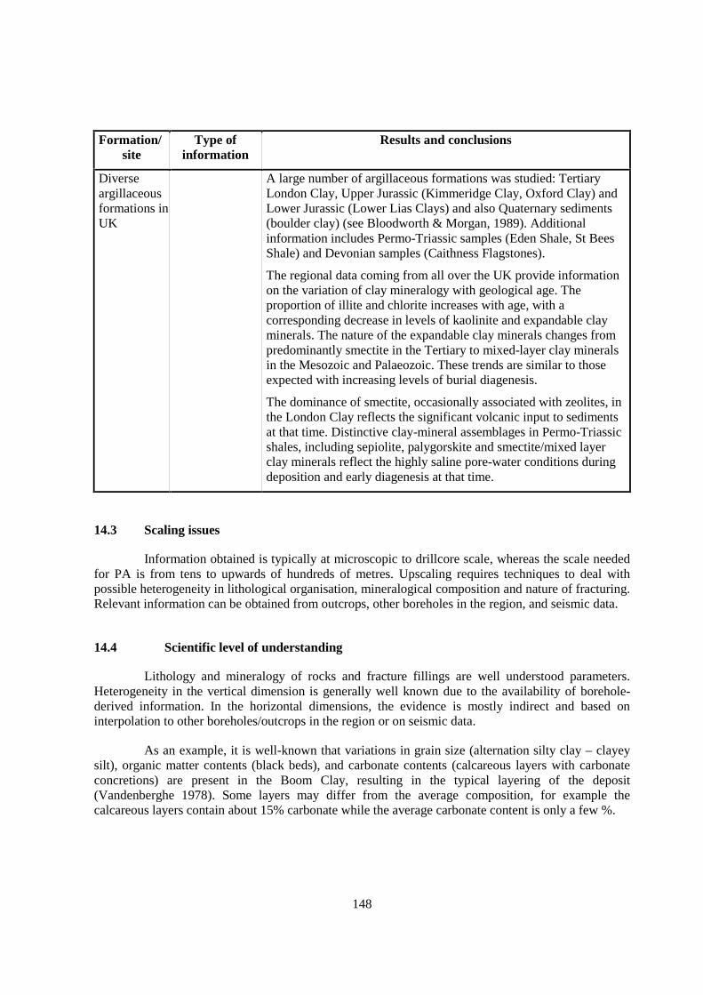
148
Formation/site
Type ofinformation
Results and conclusions
Diverseargillaceousformations inUK
A large number of argillaceous formations was studied: TertiaryLondon Clay, Upper Jurassic (Kimmeridge Clay, Oxford Clay) andLower Jurassic (Lower Lias Clays) and also Quaternary sediments(boulder clay) (see Bloodworth & Morgan, 1989). Additionalinformation includes Permo-Triassic samples (Eden Shale, St BeesShale) and Devonian samples (Caithness Flagstones).
The regional data coming from all over the UK provide informationon the variation of clay mineralogy with geological age. Theproportion of illite and chlorite increases with age, with acorresponding decrease in levels of kaolinite and expandable clayminerals. The nature of the expandable clay minerals changes frompredominantly smectite in the Tertiary to mixed-layer clay mineralsin the Mesozoic and Palaeozoic. These trends are similar to thoseexpected with increasing levels of burial diagenesis.
The dominance of smectite, occasionally associated with zeolites, inthe London Clay reflects the significant volcanic input to sedimentsat that time. Distinctive clay-mineral assemblages in Permo-Triassicshales, including sepiolite, palygorskite and smectite/mixed layerclay minerals reflect the highly saline pore-water conditions duringdeposition and early diagenesis at that time.
14.3 Scaling issues
Information obtained is typically at microscopic to drillcore scale, whereas the scale neededfor PA is from tens to upwards of hundreds of metres. Upscaling requires techniques to deal withpossible heterogeneity in lithological organisation, mineralogical composition and nature of fracturing.Relevant information can be obtained from outcrops, other boreholes in the region, and seismic data.
14.4 Scientific level of understanding
Lithology and mineralogy of rocks and fracture fillings are well understood parameters.Heterogeneity in the vertical dimension is generally well known due to the availability of borehole-derived information. In the horizontal dimensions, the evidence is mostly indirect and based oninterpolation to other boreholes/outcrops in the region or on seismic data.
As an example, it is well-known that variations in grain size (alternation silty clay – clayeysilt), organic matter contents (black beds), and carbonate contents (calcareous layers with carbonateconcretions) are present in the Boom Clay, resulting in the typical layering of the deposit(Vandenberghe 1978). Some layers may differ from the average composition, for example thecalcareous layers contain about 15% carbonate while the average carbonate content is only a few %.

149
14.5 Linked FEPs
FEP 18 Dissolution/precipitation of solid phases
FEP 24 Evolution of pore-fluid (water and gas) chemistry and mineralogy in the host formation andin embedding units
FEP 50 Past burial history
14.6 Level of understanding from a PA perspective and treatment in PA
Lithology affects both transport (advection, diffusion) and retention (matrix diffusion,sorption) properties of the rocks. In general, both vertical and large-scale lateral lithological variationsare sufficiently well known for PA purposes. One possible exception are sites that had been subjectedto intense thrusting and imbrication, such as the Wellenberg in the Swiss Alps, where the spatialdistribution of lithologies is more difficult to determine and needs to consider several datasets(boreholes, seismics, regional tectonics).
Lithology and mineralogy are not used in PA models as explicit parameters. They areconsidered indirectly in several other parameters to which they are connected, e.g. sorption Kd,porosity, diffusion coefficient, permeability, geomechanical parameters. While some programmesconsider averaged parameter values for the whole host-rock formation, others use different parametersets for different lithological units within the formation.
Mineralisations in fractures and faults occur in indurated formations and, in general, are notincluded in PA calculations. The most important question to answer is whether or not fracture coatingscould isolate flowing water from the matrix.
14.7 Available reviews
None reported.
14.8 Planned work
Boom Clay at Mol:
• Study of the long-term behaviour of natural trace elements and radionuclides in layerswith different lithological characteristics (silty clay, clayey silt, carbonate-rich, organicmatter containing).
• Uranium migration experiments in layers with different lithological characteristics (siltyclay, clayey silt, carbonate-rich, organic matter containing).
• It is planned to account for heterogeneity (layering) of the host formation in the PAcalculations.
150
Nirex (generic studies):
• Programme of laboratory experiments on relating sorption parameters to individualmineral phases and a range of rock types. The objectives are to improve the data base ofparameters applied to sorption modelling.
• Application of geophysical techniques, especially borehole electrical conductivity, tocharacterising lithological and mineralogical properties relevant to sorption and otherretardation processes (including diffusion).
14.9 Overall evaluation
Lithology and mineralogy are among the best known properties of the host formations, andin most cases conceptual models for the large-scale spatial distribution of lithologies are welldeveloped. The heterogeneous architecture of the host formation is treated explicitly in some PAs.Fracture fillings are generally well characterised and play a minor role from a PA perspective.
151
15. NATURAL ORGANICS, COMPLEXATION (FEP A2.2.2)
15.1 Definition and generalities
The term “natural organics” refers to the plethora of structurally different organic moleculespresent in the geosphere. They are formed by decay and cycling processes from plant, microbial andanimal materials. They can be subdivided into carbohydrates, lipids, amino acids/proteins and humicsubstances (HS), just to mention a few important classes. With respect to PA, the term “naturalorganics” is most often restricted to humic substances, because these are among the most importantcomplexing agents and are ubiquitously present in ground water. Humic substances are part of anoperationally defined class of structurally related molecules. They are mixtures of macromolecularorganic structures, their functional groups being to a large extent carboxylic and phenolic. The solublepart of humic substances is further subdivided into humic and fulvic acids.
Organic carbon in water is generally measured by analysing the quantity of CO2 producedwhen a water sample is oxidised. The results are expressed as TOC (total organic carbon) or DOC(dissolved organic carbon) concentrations. TOC measurements are made on samples as collected;DOC measurements are made on samples after filtration.
15.2 Site-specific experimental information
Humic substances are ubiquitously present in geological fluids at low concentrations of theorder of a few µg/l up to hundreds of mg/l (Grauer, 1989). They may increase the mobility ofradionuclides due to complexation, and they may induce changes of the redox state. Conclusions fromnatural analogue and field studies with respect to the influence of humic substances on the mobility ofradionuclides are conflicting. An overview can be found in Choppin (1992). One example showing anincrease in Cu(II) concentrations induced through increased humic-substance concentrations is givenby Lehman & Mills (1994). Organic matter can also be present in an immobile state (insoluble orultrafiltered by the argillaceous rock). This immobile organic matter can have a high sorption capacityfor the radionuclides and thus contributes considerably to the retention of radionuclides (Dierckx etal., 2000).
Formation/site
Type ofinformation Results and conclusions
Callovo-Oxfordianat Bure
Analysis ofcores
0.5 to 1% organic carbon in the rock, immature.
Toarcian-Domerian atTournemire
Analysis ofcores
Up to 1% organic carbon in the rock, very mature (Boisson et al.,1998); low complexation.
152
Formation/site
Type ofinformation Results and conclusions
SpanishReferenceClay in aTertiarybasin
Completechemicalanalysis ofpore-water butno data ondissolvedorganic matter
Not well studied at present. Included in PA through uncertaintyranges of solubilities (Enresa, 1999).
OpalinusClay in theZürcherWeinlandand atMont Terri
Aqueousextracts;
sorption tests onnatural organicsin OpalinusClay withNi(II), Eu(III)and Th(IV) andcomplexationtests withCm(III);complexationstudies withhumicsubstances
DOC ~5 to 15 mg/l.
Sorption of Ni(II), Eu(III) and Th(IV) on an ion-exchange resin wasstudied using 1) synthetic pore-water and 2) aqueous extracts ofthree samples of Opalinus Clay from Mont Terri and three samplesfrom the Benken borehole. When using the aqueous extracts, aslight reduction (less than half an order of magnitude) of sorptionon the resin was observed when compared to the synthetic pore-waters. Thus sorption on dissolved organic matter that is present inthe extracts was shown to be of limited significance.
Experiments using small molecular weight ligands and Aldrichhumic acid show that the sensitivity of the ion exchange method issufficient at the specific conditions of the Opalinus Clay extracts.The results of the accompanying fluorescent spectroscopic testexperiments using Cm(III) as a fluorescent probe do not show anyinfluence of the extracts on metal ion speciation, which isdominated by carbonate complexes. This indicates that thereduction of sorption observed in the ion exchange experiments ispossibly not caused by formation of complexes between theradionuclides and the dissolved organic matter in the extracts, but israther due to slight differences in the chemical matrix (i.e. waterchemistry) between the extracts and the synthetic reference waters.
From these findings and from a rough characterisation of thedissolved organic matter in the extracts by UV-VIS spectroscopy, itcan be concluded that only a negligible fraction of the dissolvedorganic matter may be present as humic or fulvic material. Thelargest part of the dissolved organic matter are most probably eithersmall molecular weight organic molecules or organicmacromolecules with a very low content in complexing ligand sites.The measurement of sorption distribution coefficients will not beaffected by the extractable organic matter contained in OpalinusClay.
The samples of Opalinus Clay tested can be considered to berepresentative for the formation at Mont Terri and in the ZürcherWeinland. The conclusions drawn here for organic matter obtainedfrom samples at Mont Terri can safely be conferred to the OpalinusClay in the Zürcher Weinland
153
Formation/site
Type ofinformation
Results and conclusions
SUMMARY: Dissolved organic matter has only very low content incomplexing ligand sites, with little influence on sorption(Glaus et al., 2001).
Complexation studies were also performed with pure humicsubstances (i.e. artificial materials, not derived from OpalinusClay). These are considered to be the most strongly complexingorganic materials and so represent the “worst case”. Opalinus Clayis poor in humic substances. Strong complexation of humicsubstances exists towards a series of radionuclides, such astransition metals, lanthanides and actinides (Grauer, 1989, Glaus etal., 1997, 2000, Hummel et al. 2000). From all the safety relevantradionuclides, trivalent actinide ions, such as Am(III), Cm(III), aremost strongly affected by the presence of humic substances (Glauset al., 1997, Hummel et al., 2000). The stability of metal-humatecomplexes generally increases with increasing pH and increasingratio of humic substance to metal ion concentration (Glaus et al.,1997, Hummel et al. 1999, 2000). The stability of these complexesis rather weakly influenced by changes in ionic strength and invariation of type of the humic substance (with respect to origin andsubdivision in humic and fulvic acids).
Boom Clayat Mol
Analysis of claycores, analysisof pore-waters,chargemeasurements,complexationstudies,laboratory andin situmigrationstudies
The total organic matter content of Boom Clay ranges from1 to 3 wt%. Only a small fraction is soluble and mobile. TOCcontents are 40 to 250 ppm (mean 100 ppm).
From U/Th series disequilibrium studies on Boom Clay (De Craenet al., 1999, 2000), an association was observed between U andsolid organic matter. This association was also observed in a studyusing different extraction techniques to determine the naturalU content in Boom Clay (Wang et al., 2001, 2002), but the type ofinteraction remains unknown.
More detailed studies on the complexation behaviour of U withdissolved organic matter are undertaken in the EC-projectTRANCOM-II: complexation experiments (batch) and columnexperiments (migration experiments).
Batch experiments in the laboratory: A complexation study wascarried out for trivalent lanthanides (Eu3+) and actinides (Am3+)with organic matter extracted from Boom Clay at in situ pH(around 8) and in presence of the in situ concentration of carbonate,and complexation constants were derived (Dierckx et al., 1994;Maes et al., 1988, 1991). In more recent batch experiments(Trancom-Clay, Trancom-II), the organic matter for thecomplexation experiments is taken from Boom Clay pore-watersampled in the underground research lab and then concentrated.

154
Formation/site
Type ofinformation
Results and conclusions
Column experiments in the laboratory: Site specific organicmaterial was labelled with 14C and contacted with 241Am to formAm complexes. Based on the conditional complexation constantsfrom batch experiments, the speciation was predicted to be entirelyan organic matter complex. The main result was that upon passagethrough the clay, the complex dissociates and that duringpercolation through real clay water, a rather constant but tinyconcentration (10-14 to 10-11 M) was leached from the clay core(Dierckx et al., 2000).
The conditional complexation constant for trivalent radionuclidecomplexation in solution has been implemented in the CHESS database (Van der Lee, 1998). Based on conditional complexationconstants for trivalent radionuclide complexation in solution, thedistribution of americium in the clay environment between solidand solution was predicted. The americium is said to bequantitatively sorbed (Dierckx et al., 2000).
Boda ClayFormationat Mecsek
Analysis ofcores
Almost no organic matter in shale due to oxidising conditionsduring sedimentation and diagenesis. Any remaining organicswould be highly mature. Organic matter only present in over- andunderlying aquifers.
MizunamiGroup atTono
Chemicalanalysis ofwater fromboreholes
DOC 0.1 to 8 mg/l. Trace elements such as I, Cs, Th, Cr and REEare not identified in fulvic and humic acids, i.e. they are not sorbed.Some sorption is identified for Cu and Mn (Iwatsuki & Yoshida,1999).
15.3 Scaling issues
Information about the nature of dissolved organics and their complexation with metal ions isrestricted to the laboratory scale. With respect to in situ conditions, these data are often conservativebecause conservative assumptions are made in the evaluation and modelling of the laboratoryexperiments (e.g. Glaus et al., 1997, Hummel, 1997, Hummel et al., 2000).
15.4 Scientific level of understanding
The various interactions between humic substances, ions and the solid surface are complexand not fully understood. Humic substances are known to complex especially trivalent actinides. Thereis no consensus on how to treat metal-humate interactions in a consistent way, and these interactionscannot be described using simple thermodynamic equilibrium expressions. The ligands, i.e. humicsubstances, are not well characterised chemical structures. They are rather an operationally definedmixture of naturally occurring medium and large size molecules. The mixture is heterogeneouslycomposed both in the sense of molecular size and of functional groups. Therefore, the interactions arecurrently mostly described using conditional constants or empirical relationships. There are only fewstudies on the migration of humic-substance complexes in argillaceous formations, and so themobility/immobility and stability of these complexes is poorly understood.
155
In Boom Clay at Mol, knowledge is thought to be adequate for trivalent radionuclides(Am, Cm, Pu). For other critical radionuclides, the fitted R (Kd) value lumps complexation withimmobile organic matter together with other mechanisms such as surface complexation, and so it canbe incorporated into the R (Kd) value. It is necessary to study the FEP in detail for systemunderstanding.
15.5 Linked FEPs
FEP 14 Lithology, mineralogy of rocks and fracture infills
FEP 17 Pore- and fracture water composition
FEP 21 Surface complexation
FEP 22 Thermodynamic and kinetic modelling data: The “blind use” of humic-substancecomplexation data in thermodynamic data bases is dangerous. Problems may arise whenextrapolating data measured under ideal laboratory conditions (i.e. low pH, large metal ionconcentrations) to repository relevant conditions (over-optimistic).
FEP 26 Oxidation of the host rock
FEP 27 Redox buffering capacity of the host rock
FEP 30 Organics from waste and their effect on transport properties of the host rock: Other ligandstransported from the affected field to far field may also be of importance. The identificationof the dominant ligand in a mixture of natural and artificial organic substances with respectto radionuclide complexation is an important task and has to be based both on effectivesolution concentration of the ligand and on its complexing strength (direction unclear).
FEP 31 Thermal effects on mineral stability and pore-water composition
FEP 50 Past burial history
15.6 Level of understanding from a PA perspective and treatment in PA
The current level of understanding is sufficient in some programmes (e.g. Belgium, Switzerland) toallow conservative estimates of the effect of natural organics on repository performance.Complexation with natural organics is, where relevant, treated in a conservative way in PA, eitherimplicitly by using adapted uncertainty ranges for e.g. solubility (e.g. Spain), “operational” solubility(e.g. Belgium) or, as in Switzerland, explicitly by applying a “conservative roof” model.
The Swiss “conservative roof” model (Glaus et al., 1997, Hummel 1997; Hummel et al.,2000) is an empirical approach to describe the overall effect of humic substances on the speciation ofradionuclides, and it has been specifically developed for the purposes of PA. It is based on a consistenttreatment of own measurements (Glaus et al., 1997, Glaus et al., 2000) and of a broad variety oftraceable (!) literature data. It uses empirical relationships (not deduced in a deterministic way fromthermodynamic principles) to model the interaction between metal ions and humic substances.Consequently the applicability of the model – especially with respect to pH, metal concentration, ionicstrength – is restricted to the parameter space within which the experimental data have been obtained.

156
However, this parameter space has been chosen such as to meet the needs of PA. The model reducesnoticeably the various features (i.e. metal concentration effect, pH effect, ternary complexes, organiccoating, ionic strength, competition by anions or cations, sorption), in the sense that it only comprisesthe ones that lead to an increase of the radionuclide concentration in solution. The complexationconstants can be used in a generic way, i.e. they do not depend on the type of humic substance.
A simplified treatment is used for Boom Clay at Mol. For trivalent radionuclides, theconcept of “operational solubility” is used to describe the small mobile fraction (Dierckx et al., 2000).For other critical radionuclides, the distribution between the solid and the solution is treated within aKd concept. Calculations with conservative parameters are performed to try to estimate the maximumimpact of organic complexation.
15.7 Available reviews
Swiss site-specific studies on quantification of natural organic matter and on complexingeffects of organic matter extracted from argillaceous formations: Tits et al. (1993), Lauber et al.(1998, 2000).
Boom Clay: Dierckx et al. (2000).
Literature overview and identification of PA-related needs for research: Grauer (1989).Generic work on complexation of a series of radionuclides by humic substances: Glaus et al. (1997,2000), Hummel (1997), Hummel et al. (2000).
General overview: De Cannière et al. (1996).
Belgian work published in the scientific literature: Dierckx et al. (1998), Put et al. (1998).
15.8 Planned work
Both in Switzerland and Belgium further studies are planned. These studies will be orientedto a better treatment of this FEP in PA.
The question of the actual concentration of dissolved humic substances in deep Swiss groundwater is not yet settled. Just taking dissolved organic C values as representative for the concentrationof humic substances may grossly overestimate their influence. Site specific work aiming atdetermining the overall effect of complexation of extractable natural organic matter towards selectedradionuclides (without a detailed characterisation of the organic matter) is ongoing (Lauber et al.,2000). There is not yet any experimental confirmation for the estimated equilibrium constants for thecomplexation of tetravalent actinides by humic substances available. A short study determining a fewkey points using the equilibrium dialysis ligand exchange method (Van Loon et al., 1992) wouldtherefore be desirable.

157
A large-scale diffusion experiment with 14C labelled site-specific organic material is runningin Boom Clay at Mol. The objective of this experiment is to confirm the laboratory results. Noconclusions are drawn yet and modelling is foreseen in the near future.
15.9 Overall evaluation
This FEP is relevant for argillaceous formations containing natural organics (especially immature).Although conservative data and/or models were used, the effect of natural organics on theperformance of a multi-barrier system was found to be small and limited to migration of trivalentactinides.

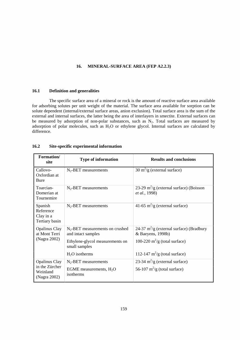
159
16. MINERAL-SURFACE AREA (FEP A2.2.3)
16.1 Definition and generalities
The specific surface area of a mineral or rock is the amount of reactive surface area availablefor adsorbing solutes per unit weight of the material. The surface area available for sorption can besolute dependent (internal/external surface areas, anion exclusion). Total surface area is the sum of theexternal and internal surfaces, the latter being the area of interlayers in smectite. External surfaces canbe measured by adsorption of non-polar substances, such as N2. Total surfaces are measured byadsorption of polar molecules, such as H2O or ethylene glycol. Internal surfaces are calculated bydifference.
16.2 Site-specific experimental information
Formation/site
Type of information Results and conclusions
Callovo-Oxfordian atBure
N2-BET measurements 30 m2/g (external surface)
Toarcian-Domerian atTournemire
N2-BET measurements 23-29 m2/g (external surface) (Boissonet al., 1998)
SpanishReferenceClay in aTertiary basin
N2-BET measurements 41-65 m2/g (external surface)
N2-BET measurements on crushedand intact samples
24-37 m2/g (external surface) (Bradbury& Baeyens, 1998b)
Opalinus Clayat Mont Terri(Nagra 2002) Ethylene-glycol measurements on
small samples100-220 m2/g (total surface)
H2O isotherms 112-147 m2/g (total surface)
N2-BET measurements 23-34 m2/g (external surface)Opalinus Clayin the ZürcherWeinland(Nagra 2002)
EGME measurements, H2Oisotherms
56-107 m2/g (total surface)
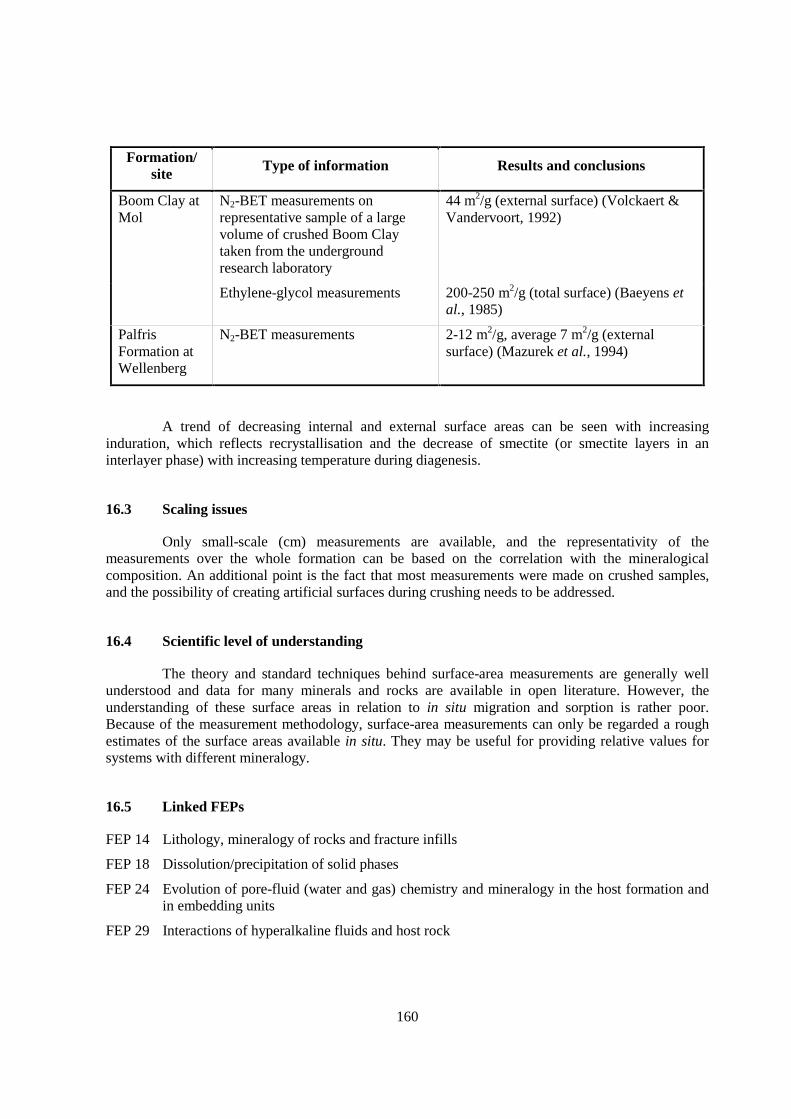
160
Formation/site Type of information Results and conclusions
Boom Clay atMol
N2-BET measurements onrepresentative sample of a largevolume of crushed Boom Claytaken from the undergroundresearch laboratory
44 m2/g (external surface) (Volckaert &Vandervoort, 1992)
Ethylene-glycol measurements 200-250 m2/g (total surface) (Baeyens etal., 1985)
PalfrisFormation atWellenberg
N2-BET measurements 2-12 m2/g, average 7 m2/g (externalsurface) (Mazurek et al., 1994)
A trend of decreasing internal and external surface areas can be seen with increasinginduration, which reflects recrystallisation and the decrease of smectite (or smectite layers in aninterlayer phase) with increasing temperature during diagenesis.
16.3 Scaling issues
Only small-scale (cm) measurements are available, and the representativity of themeasurements over the whole formation can be based on the correlation with the mineralogicalcomposition. An additional point is the fact that most measurements were made on crushed samples,and the possibility of creating artificial surfaces during crushing needs to be addressed.
16.4 Scientific level of understanding
The theory and standard techniques behind surface-area measurements are generally wellunderstood and data for many minerals and rocks are available in open literature. However, theunderstanding of these surface areas in relation to in situ migration and sorption is rather poor.Because of the measurement methodology, surface-area measurements can only be regarded a roughestimates of the surface areas available in situ. They may be useful for providing relative values forsystems with different mineralogy.
16.5 Linked FEPs
FEP 14 Lithology, mineralogy of rocks and fracture infills
FEP 18 Dissolution/precipitation of solid phases
FEP 24 Evolution of pore-fluid (water and gas) chemistry and mineralogy in the host formation andin embedding units
FEP 29 Interactions of hyperalkaline fluids and host rock
161
16.6 Level of understanding from a PA perspective and treatment in PA
The mineral surface area is not directly used in PA models. However, it is required bysurface complexation models that could be used as models supporting PA. For this purpose, the degreeof knowledge about surface area is regarded as sufficient.
16.7 Available reviews
Davis & Kent (1990), Van Olphen (1970).
16.8 Planned work
None reported.
16.9 Overall evaluation
This FEP is currently not directly treated in PA but is a necessary supporting parameter, e.g.for the extrapolation of laboratory sorption data to in situ values.

163
17. PORE- AND FRACTURE-WATER COMPOSITION (FEP A2.2.4)
17.1 Definition and generalities
The pore and fracture water composition includes the concentrations of dissolved solids andgases and of suspended solids, the values of such geochemically significant properties as pH,temperature and redox potential and the isotopic composition of water and its solutes. These data areused in both site characterisation and PA activities. They are relevant to the far field in connectionwith site characterisation and nuclide transport properties for PA and to the affected field as boundaryconditions for analysis of the engineered barrier system.
The composition of water flowing in fractures is distinguished from that in the matrix ofargillaceous rock. The matrix water is further subdivided into bound water, which is sorbed to orstructurally influenced by charged clay-mineral surfaces and edges, and free water, which is present inthe open pores of the rock. Fracture water can be sampled from conventional, surface-drilledboreholes. Matrix pore-water does not flow into such boreholes but several other techniques areavailable for its characterisation. The terminology of pore-water sample types is not standard in theliterature nor among waste management organisations. The definitions developed in the Mont TerriProject (Pearson et al., 2003) are adopted here.
The in situ pore-water chemistry is that of the free pore-water as it exists in the rock. Watersamples collected from sub-surface boreholes or piezometers represent in situ pore-water and havesuccessfully been collected from the Opalinus Clay at Mont Terri with hydraulic conductivity below10-12 m/s, and from the Boom Clay at Mol with hydraulic conductivity below 10-11 m/s. Values forsuch properties as the pH, redox potential and gas partial pressures may change during boreholesampling, but in situ values may be recoverable by geochemical modelling. Samples squeezed fromcore at high pressures or by high-speed centrifugation also represent pore-water, but are subject tomany perturbations such as oxidation and gas exchange during core collection, storage, preparationand squeezing. Very high pressure squeezing may also result in different salinity and ion ratios than inthe in situ pore-water because of ion filtration and perhaps pressure solution of minerals resulting fromthe changing pore geometry with increasing pressure. The Cl- contents of samples squeezed fromOpalinus Clay core from Mont Terri had the same Cl- content as samples from subsurface boreholeswhen squeezed at pressures up to 200 MPa, but 25% lower Cl- contents when squeezed at 512 MPa(Pearson et al., 2003, Annex 2).
The isotopic composition of matrix pore-water in a core can be measured on samplesextracted by distillation or by an isotopic exchange procedure. The concentration of readily solublesalts per mass of core material can be determined by aqueous leaching techniques. These are subject tothe same artefacts as samples obtained by squeezing and to additional reactions such as mineraldissolution and cation exchange during the leaching process. To convert salt contents per mass rock toconcentrations per mass water requires knowledge of the geochemical or free water porosity (see FEP9). Sampling methodology has recently been reviewed by Sacchi & Michelot (2000), and thetechniques used at Mont Terri are described and evaluated by Pearson et al. (2003).
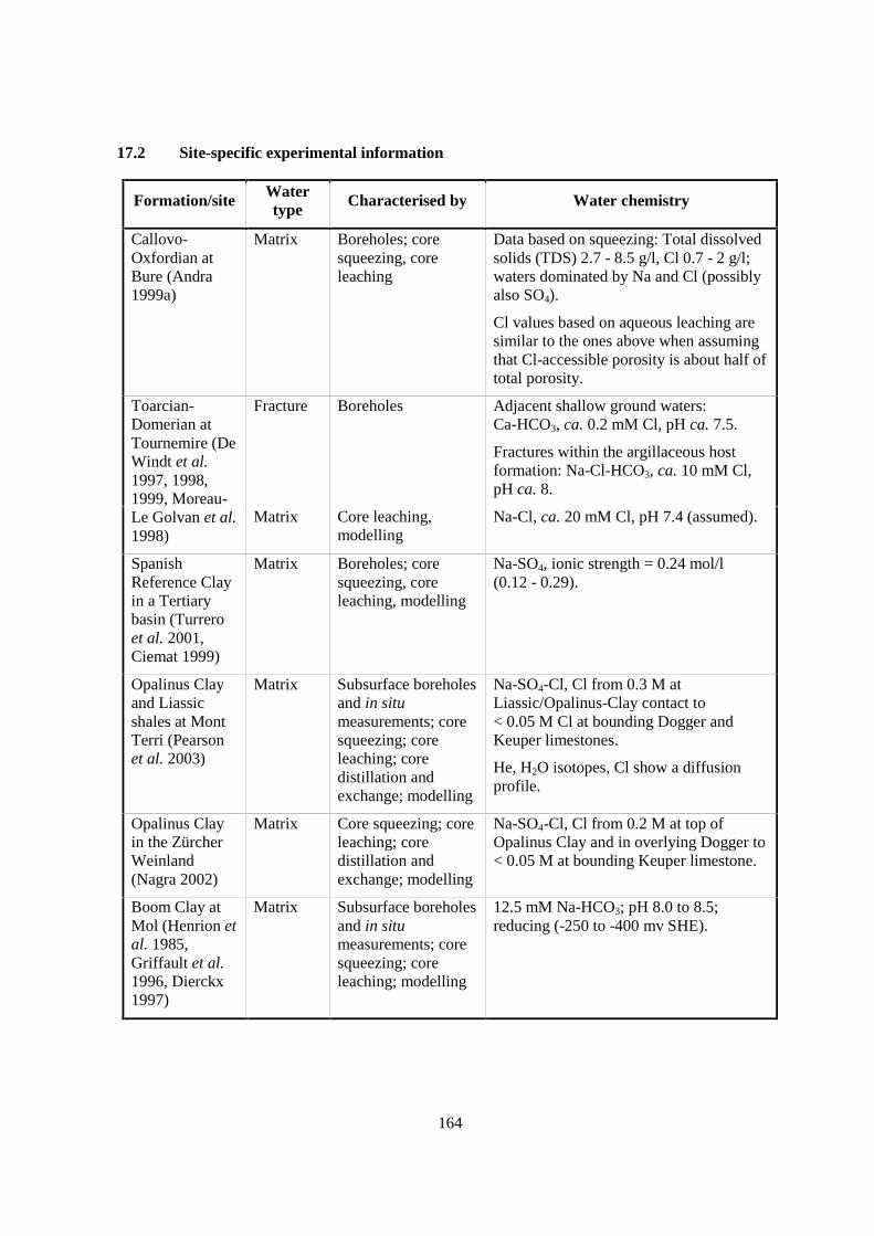
164
17.2 Site-specific experimental information
Formation/site Watertype Characterised by Water chemistry
Callovo-Oxfordian atBure (Andra1999a)
Matrix Boreholes; coresqueezing, coreleaching
Data based on squeezing: Total dissolvedsolids (TDS) 2.7 - 8.5 g/l, Cl 0.7 - 2 g/l;waters dominated by Na and Cl (possiblyalso SO4).
Cl values based on aqueous leaching aresimilar to the ones above when assumingthat Cl-accessible porosity is about half oftotal porosity.
Fracture Boreholes Adjacent shallow ground waters:Ca-HCO3, ca. 0.2 mM Cl, pH ca. 7.5.
Fractures within the argillaceous hostformation: Na-Cl-HCO3, ca. 10 mM Cl,pH ca. 8.
Toarcian-Domerian atTournemire (DeWindt et al.1997, 1998,1999, Moreau-Le Golvan et al.1998)
Matrix Core leaching,modelling
Na-Cl, ca. 20 mM Cl, pH 7.4 (assumed).
SpanishReference Clayin a Tertiarybasin (Turreroet al. 2001,Ciemat 1999)
Matrix Boreholes; coresqueezing, coreleaching, modelling
Na-SO4, ionic strength = 0.24 mol/l(0.12 - 0.29).
Opalinus Clayand Liassicshales at MontTerri (Pearsonet al. 2003)
Matrix Subsurface boreholesand in situmeasurements; coresqueezing; coreleaching; coredistillation andexchange; modelling
Na-SO4-Cl, Cl from 0.3 M atLiassic/Opalinus-Clay contact to< 0.05 M Cl at bounding Dogger andKeuper limestones.
He, H2O isotopes, Cl show a diffusionprofile.
Opalinus Clayin the ZürcherWeinland(Nagra 2002)
Matrix Core squeezing; coreleaching; coredistillation andexchange; modelling
Na-SO4-Cl, Cl from 0.2 M at top ofOpalinus Clay and in overlying Dogger to< 0.05 M at bounding Keuper limestone.
Boom Clay atMol (Henrion etal. 1985,Griffault et al.1996, Dierckx1997)
Matrix Subsurface boreholesand in situmeasurements; coresqueezing; coreleaching; modelling
12.5 mM Na-HCO3; pH 8.0 to 8.5;reducing (-250 to -400 mv SHE).
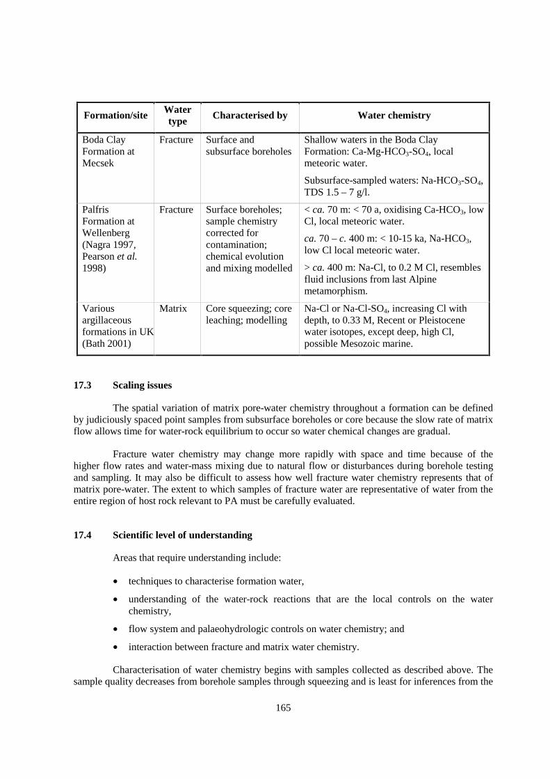
165
Formation/site Watertype Characterised by Water chemistry
Boda ClayFormation atMecsek
Fracture Surface andsubsurface boreholes
Shallow waters in the Boda ClayFormation: Ca-Mg-HCO3-SO4, localmeteoric water.
Subsurface-sampled waters: Na-HCO3-SO4,TDS 1.5 – 7 g/l.
PalfrisFormation atWellenberg(Nagra 1997,Pearson et al.1998)
Fracture Surface boreholes;sample chemistrycorrected forcontamination;chemical evolutionand mixing modelled
< ca. 70 m: < 70 a, oxidising Ca-HCO3, lowCl, local meteoric water.
ca. 70 – c. 400 m: < 10-15 ka, Na-HCO3,low Cl local meteoric water.
> ca. 400 m: Na-Cl, to 0.2 M Cl, resemblesfluid inclusions from last Alpinemetamorphism.
Variousargillaceousformations in UK(Bath 2001)
Matrix Core squeezing; coreleaching; modelling
Na-Cl or Na-Cl-SO4, increasing Cl withdepth, to 0.33 M, Recent or Pleistocenewater isotopes, except deep, high Cl,possible Mesozoic marine.
17.3 Scaling issues
The spatial variation of matrix pore-water chemistry throughout a formation can be definedby judiciously spaced point samples from subsurface boreholes or core because the slow rate of matrixflow allows time for water-rock equilibrium to occur so water chemical changes are gradual.
Fracture water chemistry may change more rapidly with space and time because of thehigher flow rates and water-mass mixing due to natural flow or disturbances during borehole testingand sampling. It may also be difficult to assess how well fracture water chemistry represents that ofmatrix pore-water. The extent to which samples of fracture water are representative of water from theentire region of host rock relevant to PA must be carefully evaluated.
17.4 Scientific level of understanding
Areas that require understanding include:
• techniques to characterise formation water,
• understanding of the water-rock reactions that are the local controls on the waterchemistry,
• flow system and palaeohydrologic controls on water chemistry; and
• interaction between fracture and matrix water chemistry.
Characterisation of water chemistry begins with samples collected as described above. Thesample quality decreases from borehole samples through squeezing and is least for inferences from the
166
rock properties. In any case, such easily disturbed properties as pH, redox potential and dissolved gasconcentrations will generally have to be inferred from modelling, except possibly for boreholesamples. With careful experimental design, it should be possible to collect sufficient information tocharacterise the water chemistry in any type of argillaceous rock.
Because of the fine grain size of argillaceous rocks and the relatively long residence time oftheir pore-water, the assumption that water-rock chemical equilibrium prevails seems acceptable.Modelling of the Opalinus and Boom Clays in which the pore-water chemistry is well definedcertainly supports this assertion. The principal minerals and reactions are common to all argillaceousrocks, but certain properties such as the cation exchange characteristics will be specific to individualformations and to the sample locations within them.
The flow system and palaeo-hydrogeology will largely determine the concentrations ofsolutes such as Cl and Br that are not controlled by water-rock reactions. In the Opalinus Clay at MontTerri, for example, the Cl origin can be established as seawater and its concentration variation acrossthe formation can be interpreted as diffusion to adjacent units in which fresh ground waters arepresent. In cores from the Benken borehole, there are fluid inclusions in quartz cements in sandylayers in the Opalinus Clay with salinities of 6.5-7.5 wt% NaCl(eq), i.e. well above seawater values.The formation there seems to have experienced a highly saline phase, perhaps related to dissolution ofthe underlying Triassic salt beds. Also, the Cl-Br ratios are not those of seawater in the Benkenborehole. In the Palfris Formation at Wellenberg, the Cl may be associated with the last metamorphicfluids affecting the region and the present decrease in Cl concentration toward the surface related tothe greater fracture flow developing near the surface.
The detailed relationship between fracture and matrix pore-water has not been evaluated atany site. This is because of the difficulties of fully defining fracture flow systems themselves (thesemay be absent in many less indurated formations) and because rocks that are indurated enough tosupport the development of substantial fracturing are generally too stiff to permit readycharacterisation of the matrix pore-water chemistry.
17.5 Linked FEPs
FEP 1 Advection/dispersion
FEP 7 Units over- and underlying the host formation: local and regional hydrogeologic framework
FEP 8 Diffusivity
FEP 10 Ion exclusion
FEP 14 Lithology, mineralogy of rocks and fracture infills
FEP 18 Dissolution / precipitation of solid phases
FEP 20 Ion exchange
FEP 21 Surface complexation
FEP 22 Thermodynamic and kinetic modelling data
FEP 24 Evolution of pore-fluid (water and gas) chemistry and mineralogy in the host formation andin embedding units
FEP 26 Oxidation of the host rock
FEP 28 Effects of repository components on pore-water chemistry in the host rock
167
FEP 29 Interactions of hyperalkaline fluids and host rock
FEP 31 Thermal effects on mineral stability and pore-water composition
FEP 43 Off-diagonal Onsager processes except chemical osmosis
FEP 44 Chemical osmosis
FEP 45 Gas dissolution and chemical interactions between gas and pore-water
FEP 49 Microbiological perturbations
FEP 50 Past burial history
17.6 Understanding from a PA perspective and treatment in PA
Generally, water chemistry is not explicitly included in PA analyses. However, it providesinformation important for site characterisation and therefore supports the design of the system forwhich the PA modelling is being performed. With the possible exception of the relationship betweenfracture and pore-water chemistry, this FEP is sufficiently well understood for this purpose.
Formation water chemistry is also important in choosing the values of certain transportparameters used in PA. These include diffusion properties, especially the porosity, and the solubilitiesand sorption properties of radionuclides. Water similar to pore-water is often used as the matrix inwhich laboratory determinations of site-specific formation properties are carried out. Certainformations, e.g. the Opalinus Clay at Mont Terri and the Boom Clay at Mol, have been sufficientlywell characterised that salinity, pH and redox properties required to establish the transport propertiesare available. This is less true of formations and sites that had received only superficial study, andfractured systems like those at the Palfris Formation at Wellenberg and the Toarcian-Domerian atTournemire.
17.7 Available reviews
The principles and practice of pore-water characterisation in argillaceous formations arereviewed by Sacchi & Michelot (2000). The extensive investigations at Mont Terri are described andcompared, and the strengths and weaknesses of the various techniques used are evaluated by Pearsonet al. (2003). The use of pore-water chemistry in choosing transport and other parameters for PAapplications is addressed in several reports cited in the discussions (FEPs 18-21). Site- and formation-specific reviews and summary reports are given above.
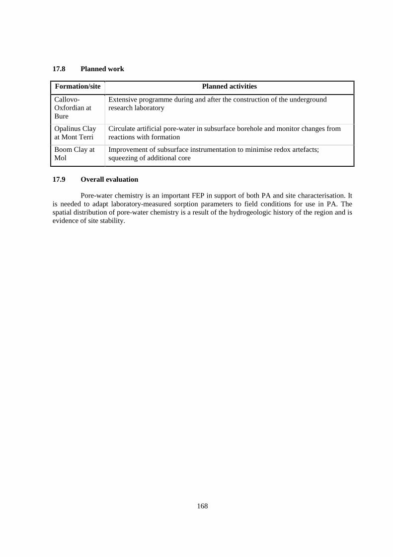
168
17.8 Planned work
Formation/site Planned activities
Callovo-Oxfordian atBure
Extensive programme during and after the construction of the undergroundresearch laboratory
Opalinus Clayat Mont Terri
Circulate artificial pore-water in subsurface borehole and monitor changes fromreactions with formation
Boom Clay atMol
Improvement of subsurface instrumentation to minimise redox artefacts;squeezing of additional core
17.9 Overall evaluation
Pore-water chemistry is an important FEP in support of both PA and site characterisation. Itis needed to adapt laboratory-measured sorption parameters to field conditions for use in PA. Thespatial distribution of pore-water chemistry is a result of the hydrogeologic history of the region and isevidence of site stability.
169
18. DISSOLUTION/PRECIPITATION OF SOLID PHASES (FEP A2.2.5)
18.1 Definition and generalities
This FEP refers to the process by which solids dissolve in and/or are precipitated fromsolutions. Dissolution/precipitation reactions occurring during diagenesis and metamorphism canchange the fabric of porous media and fractures, and minerals found in the formation may reflectdiagenetic and metamorphic events. The occurrence and extent of these reactions may affect and beaffected by the pH and redox potential of the water-rock system. This is likely to be particularlyimportant in the excavation-disturbed zone (EDZ) where oxidation is probable (FEP 26).
Dissolution/precipitation in the context of this FEP refers to pure phases. Solid solution andco-precipitation are discussed in FEP 19. These processes are relevant to the far field in connectionwith site characterisation and nuclide transport properties for PA, as well as for the affected field inconnection with the excavation-disturbed zone (EDZ).
18.2 Site-specific experimental information
Mineralogical descriptions of matrix rock and fracture fillings (FEP 14) and knowledge ofthe controls on fracture and matrix water chemistry (FEP 17) provide information about theprecipitation/dissolution of minerals in situ. Additional reactions may occur when the host rock isexposed to the atmosphere during the construction of the underground research laboratory or disposalfacility, in the EDZ (FEP 26), or in core samples, for example.
Solids that could limit radioelement concentrations are not generally observed in site studies.Instead, the possibility of their formation is inferred from the geochemistry of the water-rock-wastesystem and geochemical thermodynamic modelling (FEP 22).
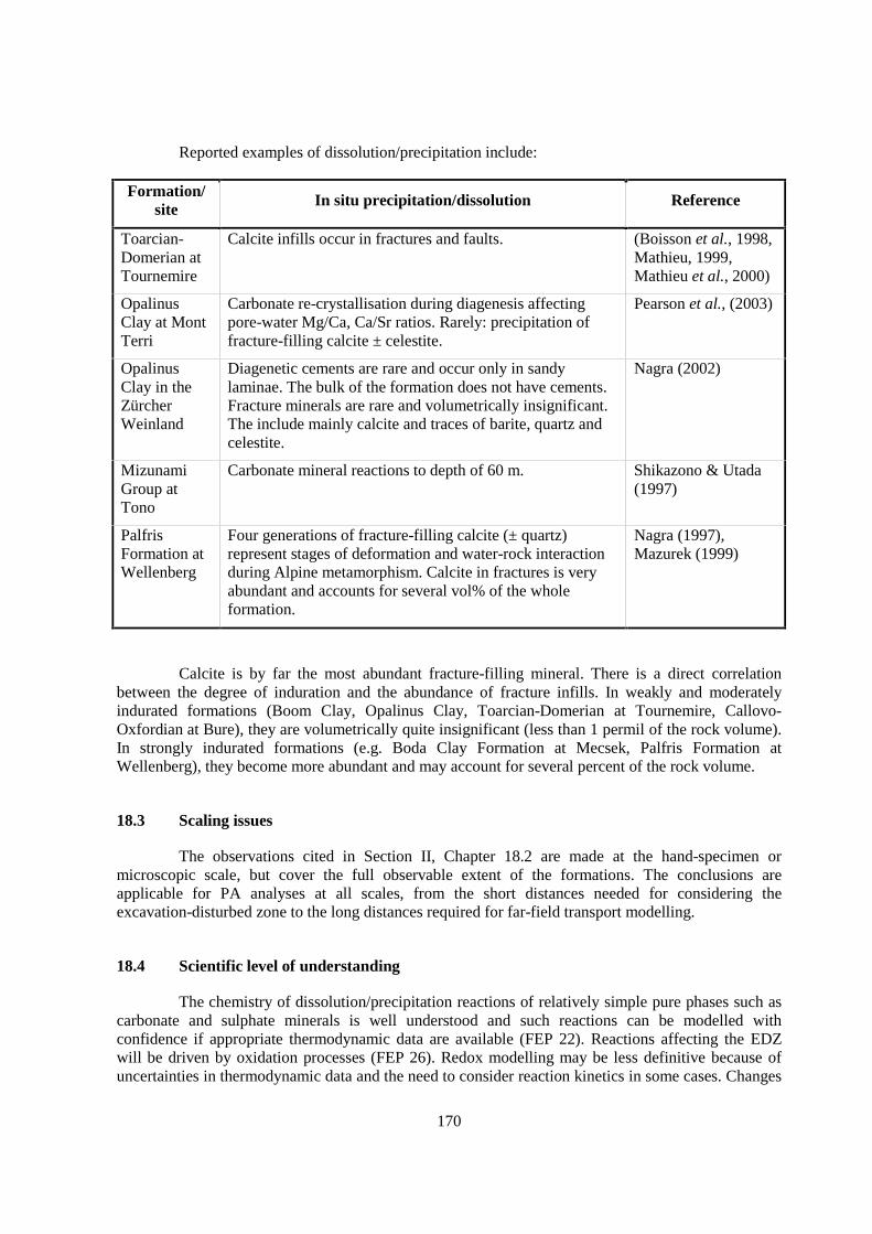
170
Reported examples of dissolution/precipitation include:
Formation/site In situ precipitation/dissolution Reference
Toarcian-Domerian atTournemire
Calcite infills occur in fractures and faults. (Boisson et al., 1998,Mathieu, 1999,Mathieu et al., 2000)
OpalinusClay at MontTerri
Carbonate re-crystallisation during diagenesis affectingpore-water Mg/Ca, Ca/Sr ratios. Rarely: precipitation offracture-filling calcite ± celestite.
Pearson et al., (2003)
OpalinusClay in theZürcherWeinland
Diagenetic cements are rare and occur only in sandylaminae. The bulk of the formation does not have cements.Fracture minerals are rare and volumetrically insignificant.The include mainly calcite and traces of barite, quartz andcelestite.
Nagra (2002)
MizunamiGroup atTono
Carbonate mineral reactions to depth of 60 m. Shikazono & Utada(1997)
PalfrisFormation atWellenberg
Four generations of fracture-filling calcite (± quartz)represent stages of deformation and water-rock interactionduring Alpine metamorphism. Calcite in fractures is veryabundant and accounts for several vol% of the wholeformation.
Nagra (1997),Mazurek (1999)
Calcite is by far the most abundant fracture-filling mineral. There is a direct correlationbetween the degree of induration and the abundance of fracture infills. In weakly and moderatelyindurated formations (Boom Clay, Opalinus Clay, Toarcian-Domerian at Tournemire, Callovo-Oxfordian at Bure), they are volumetrically quite insignificant (less than 1 permil of the rock volume).In strongly indurated formations (e.g. Boda Clay Formation at Mecsek, Palfris Formation atWellenberg), they become more abundant and may account for several percent of the rock volume.
18.3 Scaling issues
The observations cited in Section II, Chapter 18.2 are made at the hand-specimen ormicroscopic scale, but cover the full observable extent of the formations. The conclusions areapplicable for PA analyses at all scales, from the short distances needed for considering theexcavation-disturbed zone to the long distances required for far-field transport modelling.
18.4 Scientific level of understanding
The chemistry of dissolution/precipitation reactions of relatively simple pure phases such ascarbonate and sulphate minerals is well understood and such reactions can be modelled withconfidence if appropriate thermodynamic data are available (FEP 22). Reactions affecting the EDZwill be driven by oxidation processes (FEP 26). Redox modelling may be less definitive because ofuncertainties in thermodynamic data and the need to consider reaction kinetics in some cases. Changes
171
in clay-mineral assemblages in response to changing formation chemical and physical environmentsare known semi-quantitatively.
Solubilities of elements of concern in PA may be controlled by the precipitation of solids.The properties and even the identities of possible controlling phases for many elements (e.g. theactinides) are not well known so that solubilities used in PA (or the thermodynamic data from whichsuch solubilities are calculated) must be estimated (Hummel & Berner, in press) (FEP 22).
18.5 Linked FEPs
FEP 14 Lithology, mineralogy of rocks and fracture infills
FEP 17 Pore- and fracture water composition
FEP 22 Thermodynamic and kinetic modelling data
FEP 24 Evolution of pore-fluid (water and gas) chemistry and mineralogy in the host formation andin embedding units
FEP 26 Oxidation of the host rock
FEP 29 Interactions of hyperalkaline fluids and host rock
FEP 31 Thermal effects on mineral stability and pore-water composition
FEP 49 Microbiological perturbations
FEP 50 Past burial history
FEP 52 Future changes in hydrochemistry of the host rock and of surrounding formations (e.g. due toout-diffusion, water-rock interactions, uplift)
18.6 Understanding from a PA perspective and treatment in PA
The process of dissolution/precipitation is not modelled specifically in PA analyses of the farfield. However, concentration limits for radionuclides are used in the affected field of some PAmodels, These are based on solubilities calculated from formation water chemistry and other sitecharacteristics. Even if solubility limits are not explicitly included in a PA model, solubilities areconsidered in evaluating retardation (sorption) parameters used in virtually all PA models.
Immobilisation of safety-relevant nuclides by precipitation of solid phases is generallyconsidered a potential retardation mechanism (NEA, 2002a). However, such a process generallyoccurs in response to geochemical gradients (e.g. redox state, water composition). In argillaceousrocks, (except at boundaries with the EDZ or adjacent formations) the geochemical conditions in thefar field are buffered by solids (FEP 17), and thus sharp gradients, such as those occurring at redoxfronts, are unlikely.
18.7 Available reviews
None reported.
172
18.8 Planned work
Formal mineralogical characterisation of the precipitation/dissolution history will by a partof each site and formation study. Successful geochemical reaction modelling of precipitation/dissolution requires reliable thermodynamic data. Because data for many solids of PA relevance (e.g.those of the actinides) are marginal at best, thermodynamic data base development is a continuingprocess (see FEP 22).
18.9 Overall evaluation
From a generic point of view, the process of dissolution/precipitation is important as acontrol on the solubility of certain elements included in PA analyses. From a site-specific point ofview, examination of existing minerals can illuminate the geologic history of the formation and sitearea and guide the regional description of the site used in PA. Dissolution/precipitation as a result ofrepository excavation, construction and operation can affect the transport properties of the repositoryand adjacent host rock.
173
19. SOLID SOLUTIONS/CO-PRECIPITATION (FEP A2.2.6)
19.1 FEP definition
Co-precipitation is a process by which two or more chemical components are simultaneouslyand permanently incorporated into a single solid during its precipitation from solution, either inamorphous or crystalline compounds (Curti, 1997). The term solid solution refers to a special type ofco-precipitation in which a foreign component substitutes in regular lattice sites of crystallinecompounds. This definition excludes processes of surface complexation and ion exchange by which anion can be released into solution without dissolution of the solid or replacement by another ion(s) oflike charge.
The best-known, naturally-occurring solid solutions include carbonate minerals (e.g.substitution of Fe+2 for Mg+2 in dolomite forming ankerite, and the trace concentrations of alkalineearth elements, Fe+2, Mn+2 and other ions of similar size and charge in the calcite or aragonite lattice).Clay mineral groups are sometimes treated as solid solutions, but the mechanisms of their precipitationand dissolution are too poorly understood to consider them in PA. Elements of PA interest can beimmobilised or retarded by co-precipitation in solids such as ferrihydrite that may form duringdegradation of repository materials, and other solids that may form during interactions between pore-waters and repository fluids, especially those of high pH that can issue from cement.
This FEP should be considered relevant for all far-field features containing carbonate andclay minerals. These include not only the matrix of argillaceous rocks but also surface coatings andinfill of water-conducting fractures, which are commonly enriched in carbonate and clay minerals.
Co-precipitation in the affected field if cement is present should be considered relevantregardless of the type of host rock involved.
19.2 Site-specific experimental information
There appears to be no site-specific information on co-precipitation with clay minerals or inthe affected field from in situ experiments. However, there are indications from natural analogue andlaboratory studies, particularly of carbonate minerals, that this process is likely to be important to PA(Curti, 1997).
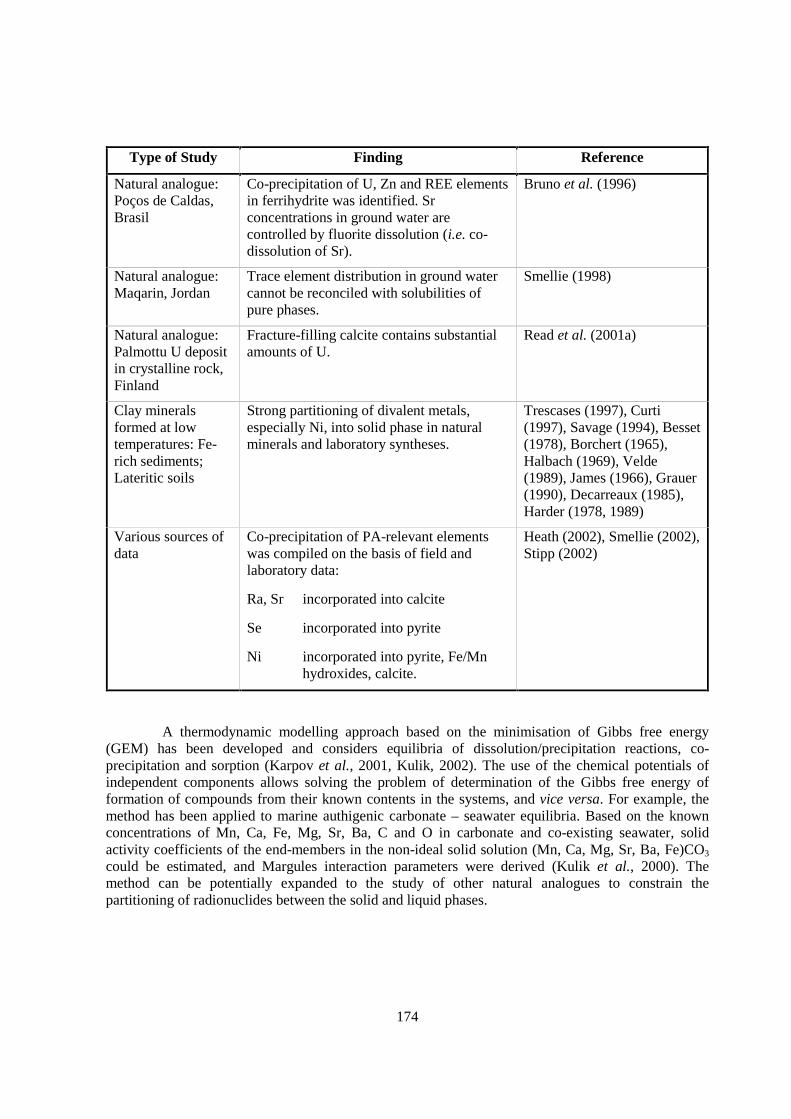
174
Type of Study Finding Reference
Natural analogue:Poços de Caldas,Brasil
Co-precipitation of U, Zn and REE elementsin ferrihydrite was identified. Srconcentrations in ground water arecontrolled by fluorite dissolution (i.e. co-dissolution of Sr).
Bruno et al. (1996)
Natural analogue:Maqarin, Jordan
Trace element distribution in ground watercannot be reconciled with solubilities ofpure phases.
Smellie (1998)
Natural analogue:Palmottu U depositin crystalline rock,Finland
Fracture-filling calcite contains substantialamounts of U.
Read et al. (2001a)
Clay mineralsformed at lowtemperatures: Fe-rich sediments;Lateritic soils
Strong partitioning of divalent metals,especially Ni, into solid phase in naturalminerals and laboratory syntheses.
Trescases (1997), Curti(1997), Savage (1994), Besset(1978), Borchert (1965),Halbach (1969), Velde(1989), James (1966), Grauer(1990), Decarreaux (1985),Harder (1978, 1989)
Various sources ofdata
Co-precipitation of PA-relevant elementswas compiled on the basis of field andlaboratory data:
Ra, Sr incorporated into calcite
Se incorporated into pyrite
Ni incorporated into pyrite, Fe/Mnhydroxides, calcite.
Heath (2002), Smellie (2002),Stipp (2002)
A thermodynamic modelling approach based on the minimisation of Gibbs free energy(GEM) has been developed and considers equilibria of dissolution/precipitation reactions, co-precipitation and sorption (Karpov et al., 2001, Kulik, 2002). The use of the chemical potentials ofindependent components allows solving the problem of determination of the Gibbs free energy offormation of compounds from their known contents in the systems, and vice versa. For example, themethod has been applied to marine authigenic carbonate – seawater equilibria. Based on the knownconcentrations of Mn, Ca, Fe, Mg, Sr, Ba, C and O in carbonate and co-existing seawater, solidactivity coefficients of the end-members in the non-ideal solid solution (Mn, Ca, Mg, Sr, Ba, Fe)CO3
could be estimated, and Margules interaction parameters were derived (Kulik et al., 2000). Themethod can be potentially expanded to the study of other natural analogues to constrain thepartitioning of radionuclides between the solid and liquid phases.
175
19.3 Scaling issues
None reported.
19.4 Scientific level of understanding
Although solid solution/co-precipitation is widely recognised to be an important mechanismfor radionuclide retention (see e.g. Nagra, 1995, p. 172), the current level of understanding is ingeneral low (NEA, 2002a, ch. 3.5.3). This is particularly true for clay minerals, which have a complexmultiple site structure and are frequently inhomogeneous at the scale of tens of nm. For this reason,safety analyses are carried out ignoring the effects of this process. To increase the knowledge in thisfield to a level which would justify incorporation in PA would require a large effort in terms of bothexperimental and modelling work by the whole scientific community. Presently, work is beingperformed by different groups in order to increase the understanding of this process in terms of basicmechanisms.
Formation of solid solutions (beyond the trace element level) could also lead tomodifications of key properties of clay minerals (e.g. sorption and swelling properties). These effectsare presently not quantifiable due to the currently poor knowledge of the chemical changes in the clayminerals, which ultimately depend on the evolution of the repository system (e.g. groundwatercomposition).
The current level of understanding in the context of the retention of radionuclides in theaffected field is also poor (Curti, 1997). Co-precipitation of radionuclides with CSH phases is theresult of the interaction of hyperalkaline fluids with the host rock. The process is operative if a sourceof hyperalkaline pore-water exists. CSH phase formation and the formation of other possiblesecondary phases in the pH plume is understood qualitatively but not quantitatively (e.g. Smellie,1998).
It is because of the lack of understanding of the mechanism of formation that solid solution /co-precipitation are not considered a robust retention mechanism in NEA (2002a). However, as thenatural analogue results show, solid solutions once formed, as by the passage of a front emanatingfrom a repository, appear persistent.
19.5 Linked FEPs
FEP 14 Lithology, mineralogy of rocks and fracture infills
FEP 17 Pore- and fracture water composition
FEP 22 Thermodynamic and kinetic modelling data
FEP 24 Evolution of pore-fluid (water and gas) chemistry and mineralogy in the host formation andin embedding units
FEP 26 Oxidation of the host rock
FEP 29 Interactions of hyperalkaline fluids and host rock

176
FEP 49 Microbiological perturbations
FEP 50 Past burial history
FEP 52 Future changes in hydrochemistry of the host rock and of surrounding formations (e.g. due toout-diffusion, water-rock interactions, uplift)
19.6 Level of understanding from a PA perspective and treatment in PA
For the reasons mentioned above, co-precipitation processes are not included in the safetyassessment models. There are, however, two approaches by which radionuclide co-precipitation couldbe included in evaluating the solubility and/or sorption coefficients to be used for PA. If a sufficientlevel of knowledge is available: (1) empirical partition coefficients could be applied based onmeasurements of the distribution of the various radionuclides between solid and aqueous phases;(2) thermodynamic solid solution models could be used. The first method implies a very largeexperimental data base for the relevant nuclides and solids. There would be no need forimplementation in a geochemical code but the requirement for data covering all relevant radionuclidesand conditions is prohibitive. Thus, this approach would be applicable to a few critical radionuclides.The second approach is based on general thermodynamic principles and could be realised with lessexperimental effort. The advantage would be a broader applicability, but implementation in advancedthermodynamic codes would be required as well as the development of the additional thermodynamicmodelling parameters requires (see FEP 22). In both cases, this FEP would be introduced in the safetyassessment model in the form of reduced solubility limits.
19.7 Available reviews
Curti (1997) reviewed the basic concepts and initial applications of co-precipitation toradioactive waste management. The mechanisms of waste stabilisation in cementitious media aredescribed in the review by Cocke & Mollah (1993). According to these authors CSH phases are primecandidates for heavy metal binding because of their abundance and appropriate structures.
Solid solution algorithms are included in most modern geochemical modelling programmes.Those in PHREEQC (Parkhurst & Appelo, 1999) for example, embody the theory described by Glynn& Reardon (1990) and Glynn & Parkhurst (1992).
The 2001 GEOTRAP workshop (NEA, 2002a) dealt with retention processes, includingimmobilisation by precipitation and co-precipitation. This topic was also taken up by one of theworking groups of the workshop.
19.8 Planned work
In the context of an ongoing European project (ACTAF), an attempt will be made tosystematise experimental data on the uptake of radionuclides by calcium carbonate (calcite) in termsof thermodynamic solid solution models. Although this work is not directly related to argillaceoussystems, it will have a “model character” for understanding the mechanisms and main parameterscontrolling solid solution formation with trace elements. Calcite has been selected due to the inherentsimplicity of its structure (only 1 cationic site) and its reactivity. Institutions involved:Forschungszentrum Rossendorf, University of Copenhagen, Paul Scherrer Institute. The project isscheduled to be completed by the end of 2003.
177
Although of less relevance to the far field, work on the co-precipitation of Sr, Ni, Eu and Thby CSH phases is in progress at the Paul Scherrer Institute. This work will be carried out until 2003,partially within the context of an ongoing European project (Ecoclay II).
19.9 Overall evaluation
Co-precipitation processes in the affected field when cement is present are likely to have abeneficial effect on radionuclide retention. However, the present status of knowledge is not sufficientto justify inclusion in PA models.
Argillaceous rocks commonly contain carbonate minerals, both in the matrix and as fracturefillings. Thermodynamic data are available for carbonate solid solutions and could be used to evaluatethe affects of this process on the solubility values used in PA.

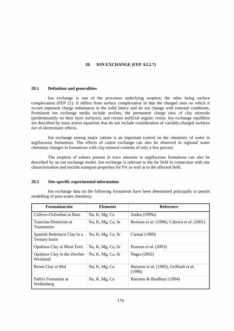
179
20. ION EXCHANGE (FEP A2.2.7)
20.1 Definition and generalities
Ion exchange is one of the processes underlying sorption, the other being surfacecomplexation (FEP 21). It differs from surface complexation in that the charged sites on which itoccurs represent charge imbalances in the solid lattice and do not change with external conditions.Prominent ion exchange media include zeolites, the permanent charge sites of clay minerals(predominantly on their layer surfaces), and certain artificial organic resins. Ion exchange equilibriaare described by mass action equations that do not include consideration of variably-charged surfacesnor of electrostatic effects.
Ion exchange among major cations is an important control on the chemistry of water inargillaceous formations. The effects of cation exchange can also be observed in regional waterchemistry changes in formations with clay-mineral contents of only a few percent.
The sorption of solutes present in trace amounts in argillaceous formations can also bedescribed by an ion exchange model. Ion exchange is relevant to the far field in connection with sitecharacterisation and nuclide transport properties for PA as well as to the affected field.
20.2 Site-specific experimental information
Ion exchange data on the following formations have been determined principally to permitmodelling of pore-water chemistry:
Formation/site Elements Reference
Callovo-Oxfordian at Bure Na, K, Mg, Ca Andra (1999a)
Toarcian-Domerian atTournemire
Na, K, Mg, Ca, Sr Boisson et al. (1998), Cabrera et al. (2001)
Spanish Reference Clay in aTertiary basin
Na, K, Mg, Ca, Sr Ciemat (1999)
Opalinus Clay at Mont Terri Na, K, Mg, Ca, Sr Pearson et al. (2003)
Opalinus Clay in the ZürcherWeinland
Na, K, Mg, Ca, Sr Nagra (2002)
Boom Clay at Mol Na, K, Mg, Ca Baeyens et al. (1985), Griffault et al.(1996)
Palfris Formation atWellenberg
Na, K, Mg, Ca Baeyens & Bradbury (1994)
180
Ion exchange data for a number of elements on pure minerals important in argillaceousformations are available in the literature (e.g. Bruggenwert & Kamphorst, 1982).
20.3 Scaling issues
Ion exchange properties are measured on point samples from core. Cation exchange is achemical process and is not scale dependent. However, total exchange capacities will vary with themineralogical composition of the formation and the proportions of exchangeable ions will vary withchanging pore-water composition. Upscaling is feasible if the large-scale distribution of mineralogyand pore-water composition is known.
Total exchange capacity and mineral-surface area of matrix rock accessible to water infractures depend on the accessibility of the matrix to pore-water. Water-rock interaction and ionexchange measurements are carried out on crushed samples. In principle, crushing could create orexpose grain surfaces not active in the in situ rock so that laboratory-measured properties may notrepresent those of the bulk rock. Surface coatings of rocks and minerals in the field are likely to playan important role in determining the geochemical or sorption properties of formations (see for exampleChapter 4 in Yariv and Cross, 1979). Because such coatings have sizes similar to the laboratorycrushed rock samples, properties determined on the latter may be reasonably representative of those ofthe bulk formation.
Fault gouges with grain sizes similar to those of artificially crushed samples may be presentas infill material in faults. Thus, laboratory-measured properties of crushed samples are likely to berepresentative of such materials. Such fault gouges occur in fractured formations such as the PalfrisFormation at Wellenberg.
20.4 Scientific level of understanding
The importance of ion exchange as a control on the chemistry of natural waters has longbeen known (e.g. Way, 1852, Foster, 1950), as has the likelihood that it will retard the transport ofradionuclides (e.g. Robinson, 1962). Ion exchange has been extensively studied, albeit with emphasison the behaviour of soils rather than of consolidated rock (Sposito, 1981, 1994) and is well understoodin pure systems (mainly bi-ionic clay systems). There is a vast amount of selectivity coefficient data inthe open literature (e.g. Bruggenwert and Kamphorst, 1982).
The application of ion exchange models to interpret sorption measurements and extend themfor use in PA is discussed by Altmann & Bruno (2001). Poinssot et al. (1999) and Bradbury &Baeyens (2000) quantitatively describe the concentration dependent sorption of Cs on argillaceousrock and pure clay minerals using a cation exchange model.
For a robust interpretation of sorption, the identity of the sorbing aqueous species must beknown. The aqueous speciation of some elements (e.g. the actinides) is not well enough understoodthat the sorbing species can always be unequivocally identified. This leads to uncertainty in theextension of laboratory measurements to field conditions (Hummel & Berner, in press; see FEP 22).
The role of cation exchange in determining pore-water chemistry has been described for anumber of argillaceous formations including the Boom Clay (Griffault et al., 1996), the PalfrisFormation (Baeyens & Bradbury, 1994, Pearson & Scholtis, 1994, Pearson et al., 1998), the Opalinus
181
Clay (Bradbury & Baeyens, 1998a, Thury & Bossart, 1999 Pearson et al., 2003) and in the MizunamiGroup in the Tono area (Iwatsuki et al., 1995).
Cation exchange algorithms are included in computer programmes used for modelling water-rock geochemical reactions and the behaviour of dissolved contaminants (see FEP 22).
Changes in water chemistry that are consistent with cation exchange, such as the tendencyfor the dominant cation to shift from Ca to Na and for the Na/K ratio to change with flow, can also beattributed to equilibria among different clay minerals, or to reactions with other silicate minerals suchas feldspars. This approach is summarised and reviewed by Langmuir (1997, Ch. 9). Pearson &Scholtis (1995) describe the cation exchange processes that lead to the changes in water chemistrywith depth in the Palfris Formation at Wellenberg. Beaucaire et al. (2000) model the chemistry ofground water near Mol using feldspar equilibria to control the Na/K ratio. Because of the uncertaintyin data available for thermodynamic properties of clay minerals and for the kinetics of reactionsamong silicates, the cation exchange formalism is more widely used (see FEPs 19 and 22)
20.5 Linked FEPs
FEP 12 Colloid formation, transport and filtration
FEP 14 Lithology, mineralogy of rocks and fracture infills
FEP 16 Mineral-surface area
FEP 17 Pore- and fracture water composition
FEP 22 Thermodynamic and kinetic modelling data
FEP 24 Evolution of pore-fluid (water and gas) chemistry and mineralogy in the host formation andin embedding units
FEP 29 Interactions of hyperalkaline fluids and host rock
FEP 31 Thermal effects on mineral stability and pore-water composition
FEP 52 Future changes in hydrochemistry of the host rock and of surrounding formations (e.g. due toout-diffusion, water-rock interactions, uplift)
20.6 Level of understanding from a PA perspective and treatment in PA
Ion exchange is one of the mechanisms generally lumped under the rubric of “sorption”, theother being surface complexation (FEP 21). Generally, PA treats sorption by means of a single solid-liquid distribution coefficient (Kd approach). In many cases mechanistic understanding e.g. ionexchange, enables sorption values to be selected (calculated) for specific chemical conditions in the insitu host rock. A mechanistic understanding of the sorption process is used to justify and defend theselected sorption values in the sorption data bases which are used in the PA (Altmann & Bruno, 2001).
20.7 Available reviews
Altmann and Bruno (2001): Review use of thermodynamic sorption models for guidingradioelement distribution coefficient (Kd) investigations for performance assessment.

182
Helfferich (1962): Ion exchange. Standard textbook.
Bolt (1982): Description of physico-chemical ion exchange models (Chaps. 2-6).
Sposito (1981, 1994): Chemical equilibria and kinetics in soils.
References to the treatment on ion exchange (and other sorption processes) in geochemicalmodelling programmes are given in FEP 22.
20.8 Planned work
Work planned by Nagra/PSI includes pore-water chemistry and sorption investigations oncrushed Opalinus Clay from the Benken borehole (laboratory experiments), and modelling the pore-water chemistry and sorption results on Opalinus Clay.
20.9 Overall evaluation
A description of radionuclide uptake processes using a formalism such as ion exchangeprovides support and justification for the sorption data bases used in PA. In systems for which directexperimental data are available for appropriate mineralogical and geochemical conditions,experimental data may be used directly for PA. For systems in which mineralogy or geochemicalconditions may change with space or time or which are not accessible in the laboratory, it will beimportant to develop (quasi) mechanistic understanding such as ion exchange on clay minerals. Suchunderstanding will permit extrapolations of sorption data bases to other mineralogical and chemicalconditions.
Inclusion of the ion exchange process and availability of site-specific ion exchange data arenecessary for the geochemical modelling needed to characterise pore-water in argillaceous media.

183
21. SURFACE COMPLEXATION (FEP A2.2.8)
21.1 Definition and generalities
Surface complexation is one of the processes underlying sorption, the other being ionexchange (FEP 20). Surface complexation is the reversible binding of dissolved species on surfaceswith charges that vary with solution chemistry and crystal-chemical effects. Both chemicalcomplexation (co-ordination) and electrostatic interaction with surfaces occur. Prominent substratesfor surface complexation include metal oxides and hydroxides of Fe (ferrihydrite, goethite), Al (α, δalumina) and Si (amorphous silica, quartz), broken bond sites on clay-mineral edges, and organicsubstances such as humic and fulvic acids and polysaccharides.
Surface complexation models are widely applied in studying the movement of pollutants insurface waters and shallow ground waters. Surface complexation occurs in all types of argillaceousmedia and is relevant in the far field for site characterisation and nuclide transport properties for PA.The processes involved are well understood and can be adequately modelled for the non-clay mineralphases that provide the main sites for surface complexation, such as hydrous ferric oxide minerals(Dzombak & Morel, 1990), manganese oxides and some silicates. However, surface complexationprocesses are less well understood on clay minerals and in complex media containing carbonates ororganics (Davis & Kent, 1990, Stumm, 1992). Ion (cation) exchange i.e. electrostatic attraction ontoconstant-charge surfaces may be a more important process than surface complexation for univalent,divalent and some trivalent cations for the basal planes of clay minerals.
21.2 Site-specific experimental information
Laboratory sorption measurements have been made for elements of importance for nuclearwaste disposal on samples of formations under study as potential host rocks. Many of these have notbeen interpreted in terms of the underlying processes, i.e. they are only applicable to the rocks fromwhich the data were derived, while extrapolations to other rock formations are difficult.
Sorption measurements interpreted in terms of surface complexation models or of two-sitesurface complexation and ion exchange models are available for a number of pure solids, minerals andbulk clay rocks. These represent the primary sources of sorptive capacity of argillaceous rocks. Theycan be used with the mineralogical composition of target host rocks to generate site-specific sorptiondata (Bradbury & Baeyens, 1997).
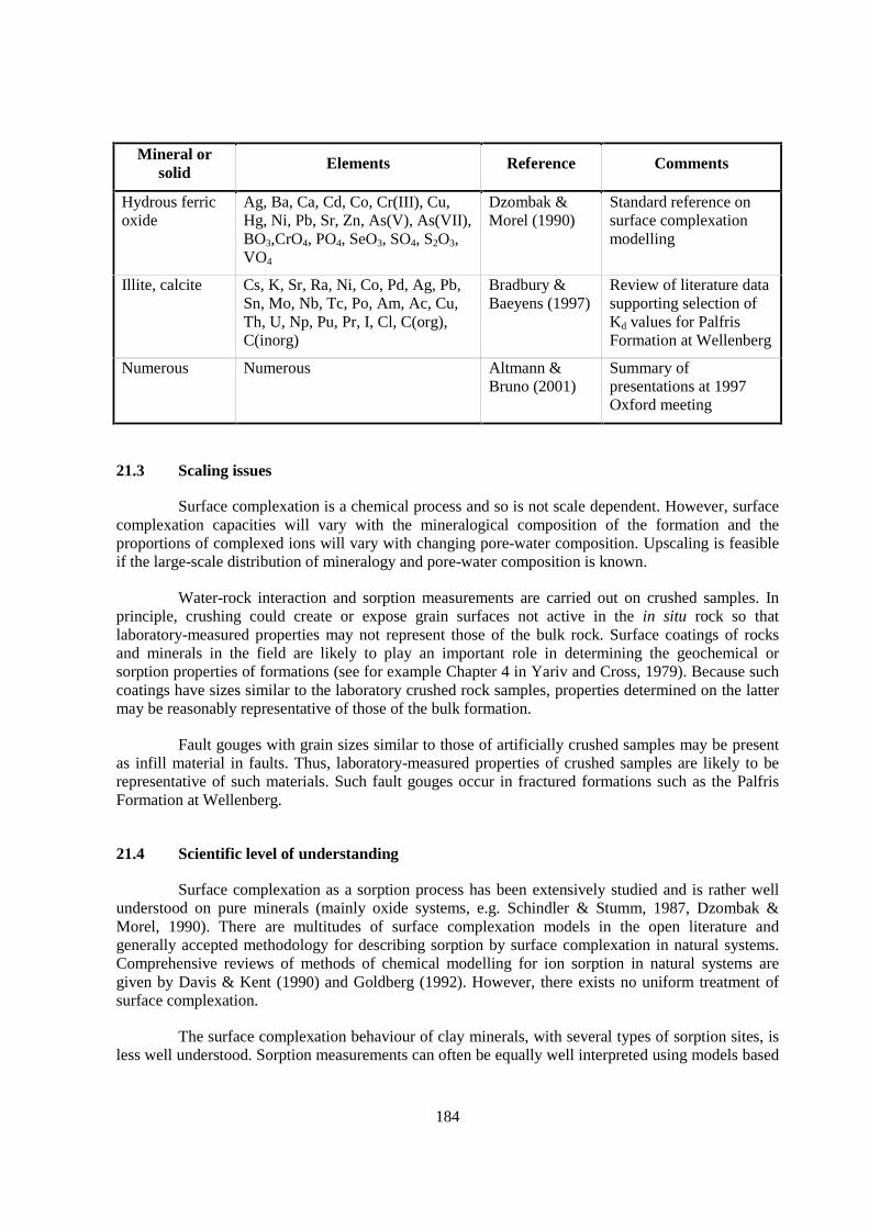
184
Mineral orsolid
Elements Reference Comments
Hydrous ferricoxide
Ag, Ba, Ca, Cd, Co, Cr(III), Cu,Hg, Ni, Pb, Sr, Zn, As(V), As(VII),BO3,CrO4, PO4, SeO3, SO4, S2O3,VO4
Dzombak &Morel (1990)
Standard reference onsurface complexationmodelling
Illite, calcite Cs, K, Sr, Ra, Ni, Co, Pd, Ag, Pb,Sn, Mo, Nb, Tc, Po, Am, Ac, Cu,Th, U, Np, Pu, Pr, I, Cl, C(org),C(inorg)
Bradbury &Baeyens (1997)
Review of literature datasupporting selection ofKd values for PalfrisFormation at Wellenberg
Numerous Numerous Altmann &Bruno (2001)
Summary ofpresentations at 1997Oxford meeting
21.3 Scaling issues
Surface complexation is a chemical process and so is not scale dependent. However, surfacecomplexation capacities will vary with the mineralogical composition of the formation and theproportions of complexed ions will vary with changing pore-water composition. Upscaling is feasibleif the large-scale distribution of mineralogy and pore-water composition is known.
Water-rock interaction and sorption measurements are carried out on crushed samples. Inprinciple, crushing could create or expose grain surfaces not active in the in situ rock so thatlaboratory-measured properties may not represent those of the bulk rock. Surface coatings of rocksand minerals in the field are likely to play an important role in determining the geochemical orsorption properties of formations (see for example Chapter 4 in Yariv and Cross, 1979). Because suchcoatings have sizes similar to the laboratory crushed rock samples, properties determined on the lattermay be reasonably representative of those of the bulk formation.
Fault gouges with grain sizes similar to those of artificially crushed samples may be presentas infill material in faults. Thus, laboratory-measured properties of crushed samples are likely to berepresentative of such materials. Such fault gouges occur in fractured formations such as the PalfrisFormation at Wellenberg.
21.4 Scientific level of understanding
Surface complexation as a sorption process has been extensively studied and is rather wellunderstood on pure minerals (mainly oxide systems, e.g. Schindler & Stumm, 1987, Dzombak &Morel, 1990). There are multitudes of surface complexation models in the open literature andgenerally accepted methodology for describing sorption by surface complexation in natural systems.Comprehensive reviews of methods of chemical modelling for ion sorption in natural systems aregiven by Davis & Kent (1990) and Goldberg (1992). However, there exists no uniform treatment ofsurface complexation.
The surface complexation behaviour of clay minerals, with several types of sorption sites, isless well understood. Sorption measurements can often be equally well interpreted using models based
185
on contradictory physical theory (e.g. comments of Morel & Kraepiel, 1997 on Baeyens & Bradbury,1997).
In unfractured argillaceous formations, the dominant transport mechanism is likely to bediffusion. The physical and mathematical models used to describe diffusional transport must beconsistent with the models used to interpret sorption data. The problems of deriving sorptionparameters from laboratory Kd measurements that are consistent with those from diffusionmeasurements have been explored for compressed bentonite considered as repository backfill, buthave not yet been resolved. There are strong analogies between the properties of compressed bentoniteand natural argillaceous media that should be considered when seeking understanding of the behaviourof either.
Surface complexation on organic matter could be an important retardation mechanism informations such as the Boom Clay with significant organic carbon contents. However, too little isknown about the process for it to be included in PA.
Due to the limitations of spectroscopic techniques, the existence of surface complexation onclay-mineral/natural organic surfaces is yet to be confirmed – here, surface complexation is more amodel concept than a real process. The method of calculating sorption as the sum of differentprocesses, i.e., ion exchange, surface complexation, surface precipitation, is model dependent.
21.5 Linked FEPs
FEP 12 Colloid formation, transport and filtration
FEP 14 Lithology, mineralogy of rocks and fracture infills
FEP 15 Natural organics, complexation: Increasing degree of complexation of radionuclides byhumic substances may lead to decreasing sorption. Neglecting the effect of radionuclidecomplexation by humic substances may lead to an over-estimation of sorption (over-optimistic).
FEP 16 Mineral-surface area
FEP 17 Pore- and fracture water composition
FEP 22 Thermodynamic and kinetic modelling data
FEP 24 Evolution of pore-fluid (water and gas) chemistry and mineralogy in the host formation andin embedding units
FEP 26 Oxidation of the host rock
FEP 29 Interactions of hyperalkaline fluids and host rock
FEP 30 Organics from waste and their effect on transport properties of the host rock
FEP 31 Thermal effects on mineral stability and pore-water composition
FEP 52 Future changes in hydrochemistry of the host rock and of surrounding formations (e.g. due toout-diffusion, water-rock interactions, uplift)
21.6 Level of understanding from a PA perspective and treatment in PA
PA models do not include surface complexation directly but treat sorption by means of asingle solid-liquid distribution coefficient (Kd approach). This approach is generally regarded assufficient for PA purposes. Uncertainties are covered by the choice of conservative (i.e. low) Kd
186
values. In many cases mechanistic understanding based on surface complexation and ion exchange isused to justify and defend the values selected for the sorption data bases used in PA (Altmann &Bruno 2001, Bradbury & Baeyens, 1997).
In the Spanish preliminary PA in clay (Enresa, 1999) the input data used to model thetransport through the clay formation are the apparent and effective diffusion coefficients (De and Da).For modelling, these data are transformed into values of the pore diffusion coefficients (Dp), accessibleporosity and distribution coefficients (Kd) that reproduce the desired values of De and Da. In thisassessment, the radionuclides that cause the greatest doses are two non-sorbing species: 129I and 36Cl.
21.7 Available reviews
There are numerous reviews in the open literature on surface complexation and on sorption.The review of the use of thermodynamic sorption models for guiding radioelement distributioncoefficient (Kd) investigations for PA by Altmann and Bruno (2001) is particularly timely andrelevant. Reviews specifically on surface complexation modelling include the definitive 1990 reportsby Dzombak & Morel (1990) and Davis & Kent (1990). More recent short reviews developing thesurface complexation modelling approach is included in Davis et al. (1998). These authors discuss theapplication of the surface complexation concept to rock surfaces with several minerals providingsurface complexation sites and review the success of non-electrostatic sorption models. Sposito (1981,1994) describes surface complexation among other chemical processes active in soils. References tothe treatment of surface complexation and ion exchange in geochemical modelling programmes aregiven in FEP 22.
21.8 Planned work
Work is planned in Switzerland to continue laboratory investigations of crushed OpalinusClay samples from the Benken borehole and to perform surface complexation modelling of thesorption results on Opalinus Clay from Mont Terri and the Benken borehole.
In the ongoing TRANCOM-Clay phase II project, a 3-year study of interaction betweenradionuclides and Boom Clay is planned for batch, column, and in situ experiments. The objective isto study the effect of natural organic matter on the mobility of radionuclides under a reducingcondition. The proposed project involves SCK•CEN (co-ordinator) and K.U.Leuven (B), University ofLoughborough (UK), Galson Sciences (UK) and Ecole des Mines (Armines, F).
21.9 Overall evaluation
Sorption, quantified as Kd values, is extremely important in describing radionuclide transportbehaviour in PA models. Kd values are commonly based on laboratory batch experiments with purephases or on bulk host rock, or found from Da and De values measured on host rock samples. PAmodels use Kd models directly. In the case that in situ conditions cannot be satisfactorily simulated inthe laboratory or if more than empirical support is desired for data used for PA, (quasi) mechanisticexplanations such as surface complexation for radionuclide uptake processes on (hydr)oxides and clayminerals are useful. Such understanding makes it possible to justify and defend values selected for thesorption data bases used in PA. Further, the influence of changing mineralogies and water chemistriescan be predicted over a large range.

187
22. THERMODYNAMIC AND KINETIC MODELLING DATA (FEP A2.2.9)
22.1 Definition and generalities
Thermodynamic data are used to support equilibrium modelling of geochemical reactionsthat occur throughout the waste isolation system. They include temperature-dependent values ofequilibrium constants for the dissolution of solids and gases in water, for redox reactions, and for theformation of solute complexes (ion pairs) in solution. Species-specific values for parameters of theactivity coefficient expressions chosen for the modelling of the solution and of solids must also beknown. Data for ion exchange and surface complexation equilibria are considered in FEPs 20 and 21.
Most geochemical programmes model equilibrium for water-mineral reactions controllingthe matrix water chemistry of argillaceous formations. This is acceptable because of the fine grain sizeof the minerals and the long residence times of pore-water in such poorly transmissive media.Geochemical equilibrium models are not used directly in assessing site performance, but are requiredfor site characterisation activities (FEP 17) and for developing parameter values used in PA(FEPs 18-21). The results of geochemical modelling are no more reliable than the thermodynamic datasupporting them.
Kinetic data include temperature-dependent reaction rates. The assumption of geochemicalequilibrium may not be justified for reactions among silicate minerals in the host rock and for thesereactions kinetic data may be required.
Sorption Kd values actually used in PA are not included in geochemical equilibrium modelsand so are not considered to be thermodynamic data as the term is used in this FEP. However, both ionexchange and surface complexation processes are included in most current geochemical modellingcomputer programmes.
22.2 Site-specific experimental information
In principle, thermodynamic data are generic and should be valid for use at all sites. Anumber of data compilations have been made, which are so widely known they do not require citationshere. There are also critically reviewed compilations of data of particular relevance to nuclearprogrammes, such as the NEA reviews for uranium (Grenthe et al., 1992), americium (Silva et al.,1995), plutonium and neptunium (Lemire et al., 2001) and for Ni, Se and organic ligands (inprogress). Many nuclear waste programmes, including Nagra (Hummel et al., 2002a,b), JNC andNirex (Cross & Ewart, 1990) have generated thermodynamic data sets for their specific use.
Geochemical modelling programmes such as EQ3/EQ6 (Wolery, 1992), MINEQL(MINSORB) (Westall et al., 1976; Bradbury & Baeyens, 1994), MINTEQA2 (Allison et al., 1991;USEPA 1999a, b), PHREEQC (Parkhurst & Appelo 1999), CHEMAPP (Eriksson et al. 1995, 1997)and The Geochemist’s Workbench® (Bethke, 1994) make use of these data and include data bases of
188
their own. Bethke (1996, App. 1) and Langmuir (1997) provide more comprehensive lists ofgeochemical modelling software and give sources for further information about each programme.
22.3 Scaling issues
Because the thermodynamic data referred to in this FEP are generic, scaling is not an issue.
22.4 Scientific level of understanding
Although a great many thermodynamic data are available in the general literature andspecifically for nuclear waste work, the data sets are generally not complete and include considerableuncertainties. These uncertainties are particularly evident in data for elements commonly present intrace quantities and may lead to uncertainties in solubilities, for example, that may need to explicitlyconsidered in PA. Missing data may lead to incorrect calculation of the aqueous speciationinformation used to extend and justify laboratory Kd data for PA use.
To overcome the problem of missing data, problem-specific estimates of data may be neededto rationally develop solubility values and extend sorption data. The relationship betweenthermodynamic data bases and parameter values used in PA is described by Hummel & Berner (inpress).
Kinetic data for mineral precipitation/dissolution are far from complete. Kinetics of redoxreactions are not well understood.
22.5 Linked FEPs
In principle, thermodynamic and kinetic data are independent of all other FEPs. However,the specific needs for such data is constrained by the minerals and the geochemical and thermalenvironments, which in turn are defined by the following FEPs:
FEP 14 Lithology, mineralogy of rocks and fracture infills
FEP 17 Pore- and fracture water composition
FEP 26 Oxidation of the host rock
FEP 29 Interactions of hyperalkaline fluids and host rock
FEP 31 Thermal effects on mineral stability and pore-water composition
22.6 Level of understanding from a PA perspective and treatment in PA
Thermodynamic data are not used directly in PA. However, the geochemical models theysupport are required to develop the knowledge of pore-water chemistry needed for site characterisationand to guide the conditions chosen for laboratory experiments, and to evaluate the solubility andsorption values actually used in the PA.
Carefully compiled thermodynamic data bases (e.g. Hummel et al., 2002b) contain sufficientdata of quality adequate to permit modelling of pore-water chemistry for PA purposes. On the otherhand, there is insufficient and/or only poor quality thermodynamic data for many of the less common
189
elements, particularly the actinides and other radioelements, that are important for PA calculations.Techniques for developing thermodynamic data are well understood (e.g. Hummel et al., 2002b), butnot fully applied at present. Thus, techniques to identify and evaluate missing data are used instead(Hummel and Berner, 2002).
22.7 Available reviews
Thermodynamic data base selection and contents development are discussed in manystandard textbooks such as Stumm & Morgan (1996), Nordstrom & Munoz (1994) and Langmuir(1997). The NEA volumes and the reports describing thermodynamic data bases used in various wastemanagement programmes listed in Section II, Chapter 22.2 also discuss the data selection process. Therecent Nagra/PSI data base report includes a particularly valuable discussion of data base consistency(Hummel et al., 2002a).
22.8 Planned work
Thermodynamic data bases are under continuous development in many programmes.
22.9 Overall evaluation
Thermodynamic data are required to support the geochemical modelling that is part of allwaste management programmes. Such data bases accompany all widely-used geochemical modellingprogrammes. Data bases for waste management use may need additional constituents and willcertainly need to be checked for internal consistency and precision before applying them to developvalues for parameters used in PA.

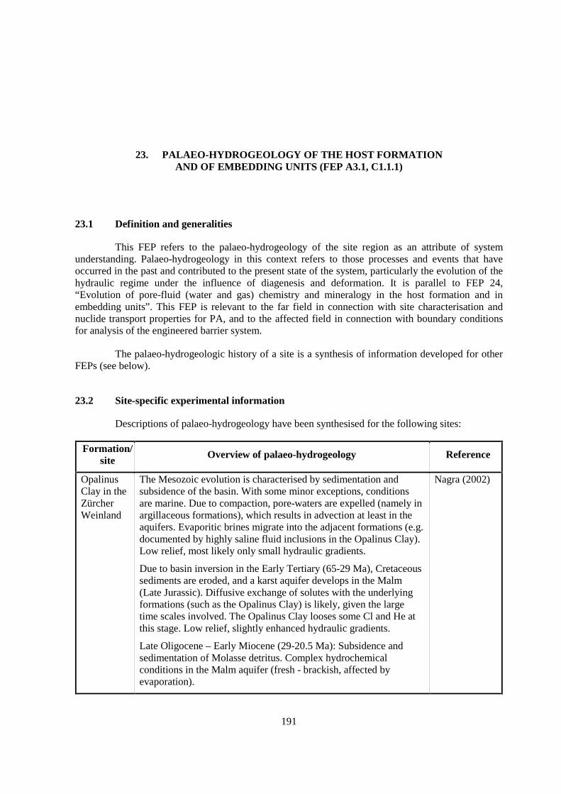
191
23. PALAEO-HYDROGEOLOGY OF THE HOST FORMATIONAND OF EMBEDDING UNITS (FEP A3.1, C1.1.1)
23.1 Definition and generalities
This FEP refers to the palaeo-hydrogeology of the site region as an attribute of systemunderstanding. Palaeo-hydrogeology in this context refers to those processes and events that haveoccurred in the past and contributed to the present state of the system, particularly the evolution of thehydraulic regime under the influence of diagenesis and deformation. It is parallel to FEP 24,“Evolution of pore-fluid (water and gas) chemistry and mineralogy in the host formation and inembedding units”. This FEP is relevant to the far field in connection with site characterisation andnuclide transport properties for PA, and to the affected field in connection with boundary conditionsfor analysis of the engineered barrier system.
The palaeo-hydrogeologic history of a site is a synthesis of information developed for otherFEPs (see below).
23.2 Site-specific experimental information
Descriptions of palaeo-hydrogeology have been synthesised for the following sites:
Formation/site Overview of palaeo-hydrogeology Reference
OpalinusClay in theZürcherWeinland
The Mesozoic evolution is characterised by sedimentation andsubsidence of the basin. With some minor exceptions, conditionsare marine. Due to compaction, pore-waters are expelled (namely inargillaceous formations), which results in advection at least in theaquifers. Evaporitic brines migrate into the adjacent formations (e.g.documented by highly saline fluid inclusions in the Opalinus Clay).Low relief, most likely only small hydraulic gradients.
Due to basin inversion in the Early Tertiary (65-29 Ma), Cretaceoussediments are eroded, and a karst aquifer develops in the Malm(Late Jurassic). Diffusive exchange of solutes with the underlyingformations (such as the Opalinus Clay) is likely, given the largetime scales involved. The Opalinus Clay looses some Cl and He atthis stage. Low relief, slightly enhanced hydraulic gradients.
Late Oligocene – Early Miocene (29-20.5 Ma): Subsidence andsedimentation of Molasse detritus. Complex hydrochemicalconditions in the Malm aquifer (fresh - brackish, affected byevaporation).
Nagra (2002)
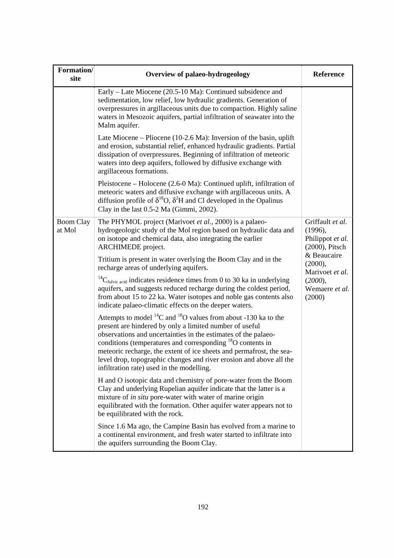
192
Formation/site
Overview of palaeo-hydrogeology Reference
Early – Late Miocene (20.5-10 Ma): Continued subsidence andsedimentation, low relief, low hydraulic gradients. Generation ofoverpressures in argillaceous units due to compaction. Highly salinewaters in Mesozoic aquifers, partial infiltration of seawater into theMalm aquifer.
Late Miocene – Pliocene (10-2.6 Ma): Inversion of the basin, upliftand erosion, substantial relief, enhanced hydraulic gradients. Partialdissipation of overpressures. Beginning of infiltration of meteoricwaters into deep aquifers, followed by diffusive exchange withargillaceous formations.
Pleistocene – Holocene (2.6-0 Ma): Continued uplift, infiltration ofmeteoric waters and diffusive exchange with argillaceous units. Adiffusion profile of δ18O, δ2H and Cl developed in the OpalinusClay in the last 0.5-2 Ma (Gimmi, 2002).
Boom Clayat Mol
The PHYMOL project (Marivoet et al., 2000) is a palaeo-hydrogeologic study of the Mol region based on hydraulic data andon isotope and chemical data, also integrating the earlierARCHIMEDE project.
Tritium is present in water overlying the Boom Clay and in therecharge areas of underlying aquifers.14Cfulvic acid indicates residence times from 0 to 30 ka in underlyingaquifers, and suggests reduced recharge during the coldest period,from about 15 to 22 ka. Water isotopes and noble gas contents alsoindicate palaeo-climatic effects on the deeper waters.
Attempts to model 14C and 18O values from about -130 ka to thepresent are hindered by only a limited number of usefulobservations and uncertainties in the estimates of the palaeo-conditions (temperatures and corresponding 18O contents inmeteoric recharge, the extent of ice sheets and permafrost, the sea-level drop, topographic changes and river erosion and above all theinfiltration rate) used in the modelling.
H and O isotopic data and chemistry of pore-water from the BoomClay and underlying Rupelian aquifer indicate that the latter is amixture of in situ pore-water with water of marine originequilibrated with the formation. Other aquifer water appears not tobe equilibrated with the rock.
Since 1.6 Ma ago, the Campine Basin has evolved from a marine toa continental environment, and fresh water started to infiltrate intothe aquifers surrounding the Boom Clay.
Griffault et al.(1996),Philippot et al.(2000), Pitsch& Beaucaire(2000),Marivoet et al.(2000),Wemaere et al.(2000)

193
23.3 Scaling issues
Palaeo-hydrogeology integrates events and processes that occurred over large scales in space(site scale to regional scale) and in time (ka – Ma). Palaeo-hydrogeological arguments can be used tosupport extrapolations of hydrodynamic and hydrochemical processes that were originallycharacterised on small spatial and temporal scales.
23.4 Scientific level of understanding
Reconstructing the palaeo-hydrogeology of a region is straightforward if the informationdescribed in Section II, Chapter 23.2 is available. The quality and reliability of the reconstructiondepends directly on the amount and quality of the supporting data.
23.5 Linked FEPs
This FEP synthesises the interaction and the effects of most FEPs of the A (Undisturbedsystem) and C (Long-term evolution) groups.
23.6 Level of understanding from a PA perspective and treatment in PA
The site properties and attributes on which a PA is based must be consistent with its palaeo-hydrogeology. Events occurring during the hydrogeologic evolution of a site may also suggestscenarios for future site behaviour.
23.7 Available reviews
NEA (1993, 1999b).
23.8 Overall evaluation
The synthesis called for by this FEP requires evaluation of site characterisation data from anumber of disciplines. Its successful completion addresses the quality, completeness and internalconsistency of the supporting data and adds credibility to the site model defined for PA.

195
24. EVOLUTION OF PORE-FLUID (WATER AND GAS) CHEMISTRY ANDMINERALOGY IN THE HOST FORMATION AND IN EMBEDDING UNITS
(FEP A3.2, C1.1.2)
24.1 Definition and generalities
This FEP addresses the evolution of fluids such as water and gases and water-rockinteractions during past basin evolution. It is a synthesis of information on the present fluid chemistryand mineralogy of the formation. The latter includes the identity of minerals present in the formation,their distribution and fabric, their chemical and isotopic compositions and other attributes such as fluidinclusions that may indicate presently or previously active water-rock reactions and transportprocesses. Likewise, the absence of certain minerals or reactions may mark the limits of penetration ofpast fluids. Knowledge of past and ongoing processes of fluid and mineral evolution will guideselection of the processes that should be considered in PA.
This FEP is parallel to FEP 23, “Palaeo-hydrogeology of the host formation and of theembedding units”. It is relevant to the far field in connection with site characterisation and the nuclidetransport properties for PA, and to the affected field in connection with the boundary conditions foranalysis of the engineered barrier system.
Fluids affecting the formation during its geological history include waters of deposition,diagenetic, metamorphic and magmatic fluids, and infiltrating surface water. Fluid evolution can bestudied indirectly by detecting signs of water-rock interaction in matrix minerals and in fracture andvein fillings, and directly by measuring the chemical and isotopic compositions of fluids presentlyfound in the interconnected pore space as well as in fluid inclusions in the target formation and itsneighbours.
Water-rock reactions occur in all types of argillaceous media. It is important to distinguishbetween matrix and vein or fracture minerals, and among different generations of veins and fractures.Water-rock reactions at fracture boundaries can give natural evidence about the extent of matrixdiffusion.

196
24.2 Site-specific experimental information
Formation/site Results and conclusions Reference
Toarcian-Domerian atTournemire
A number of pore-water tracers were investigated in verticalprofiles across the formation. 2H and Cl can be interpreted torepresent diffusion profiles, even though the mathematical fitsrequire different parameter sets for these tracers. Using De valuesfor HTO measured in the laboratory and assuming seawater as theinitial pore-water composition leads to build-up times for thediffusion profiles of ca. 50 Ma, which is unrealistic because theage of the embedding aquifers is 25 Ma at most. The discrepancyremains open at the present stage.
Variations of water isotopes were also analysed in small-scaleprofiles around water-conducting fractures. A disturbance can beidentified within 1 m away from the fractures, even though theprofile is complex and does not allow a simple interpretation.
Moreau- LeGolvan(1997),Boisson et al.(1998),Patriarche(2001)
OpalinusClay at MontTerri
Modelling of pore-water chemistry at Mont Terri indicatesequilibrium with carbonate, and sulphate minerals andexchangeable cation capacities of clay minerals observed information. Br/Cl, SO4/Cl, δ34SSO4, δ 18OSO4 of pore-water aresimilar to those of seawater (see also FEP 25). Stable waterisotopes show the same, and in addition record diffusionalexchange with surrounding fresh waters.
Pore-water within the Opalinus Clay and the Jurensis Marlsretained its initial seawater character until the Jura Uplift whencirculation of meteoric water began in relatively permeablehorizons just above and below. At that time, diffusive loss ofhelium and diffusive exchange of isotopic forms of water beganbetween the in situ pore-water and the adjacent meteoric water.Characteristic diffusion profiles of a number of tracers developedand can be evaluated quantitatively. Cl content of the formationhas dropped only about 40% from its initial seawater value, δ2Hand δ 18O values of the in situ pore-water have reached only 70%of the meteoric water values, and the He profile in the pore-waters is in secular equilibrium between in situ production anddiffusive loss, a state which requires some 4 Ma to becomeestablished.
Thury &Bossart(1999),Pearson et al.(2003), Rübelet al. (2002)
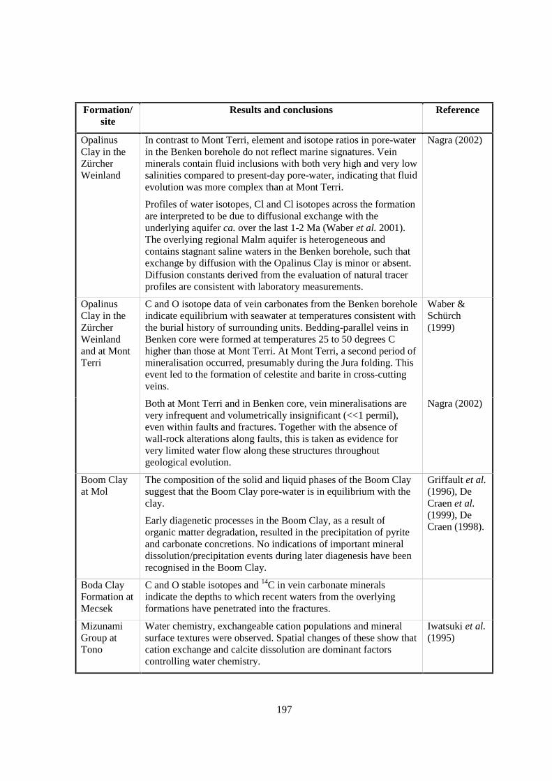
197
Formation/site
Results and conclusions Reference
OpalinusClay in theZürcherWeinland
In contrast to Mont Terri, element and isotope ratios in pore-waterin the Benken borehole do not reflect marine signatures. Veinminerals contain fluid inclusions with both very high and very lowsalinities compared to present-day pore-water, indicating that fluidevolution was more complex than at Mont Terri.
Profiles of water isotopes, Cl and Cl isotopes across the formationare interpreted to be due to diffusional exchange with theunderlying aquifer ca. over the last 1-2 Ma (Waber et al. 2001).The overlying regional Malm aquifer is heterogeneous andcontains stagnant saline waters in the Benken borehole, such thatexchange by diffusion with the Opalinus Clay is minor or absent.Diffusion constants derived from the evaluation of natural tracerprofiles are consistent with laboratory measurements.
Nagra (2002)
OpalinusClay in theZürcherWeinlandand at MontTerri
C and O isotope data of vein carbonates from the Benken boreholeindicate equilibrium with seawater at temperatures consistent withthe burial history of surrounding units. Bedding-parallel veins inBenken core were formed at temperatures 25 to 50 degrees Chigher than those at Mont Terri. At Mont Terri, a second period ofmineralisation occurred, presumably during the Jura folding. Thisevent led to the formation of celestite and barite in cross-cuttingveins.
Waber &Schürch(1999)
Both at Mont Terri and in Benken core, vein mineralisations arevery infrequent and volumetrically insignificant (<<1 permil),even within faults and fractures. Together with the absence ofwall-rock alterations along faults, this is taken as evidence forvery limited water flow along these structures throughoutgeological evolution.
Nagra (2002)
Boom Clayat Mol
The composition of the solid and liquid phases of the Boom Claysuggest that the Boom Clay pore-water is in equilibrium with theclay.
Early diagenetic processes in the Boom Clay, as a result oforganic matter degradation, resulted in the precipitation of pyriteand carbonate concretions. No indications of important mineraldissolution/precipitation events during later diagenesis have beenrecognised in the Boom Clay.
Griffault et al.(1996), DeCraen et al.(1999), DeCraen (1998).
Boda ClayFormation atMecsek
C and O stable isotopes and 14C in vein carbonate mineralsindicate the depths to which recent waters from the overlyingformations have penetrated into the fractures.
MizunamiGroup atTono
Water chemistry, exchangeable cation populations and mineralsurface textures were observed. Spatial changes of these show thatcation exchange and calcite dissolution are dominant factorscontrolling water chemistry.
Iwatsuki et al.(1995)
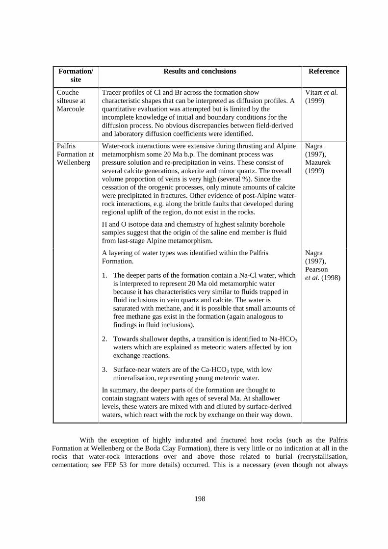
198
Formation/site
Results and conclusions Reference
Couchesilteuse atMarcoule
Tracer profiles of Cl and Br across the formation showcharacteristic shapes that can be interpreted as diffusion profiles. Aquantitative evaluation was attempted but is limited by theincomplete knowledge of initial and boundary conditions for thediffusion process. No obvious discrepancies between field-derivedand laboratory diffusion coefficients were identified.
Vitart et al.(1999)
PalfrisFormation atWellenberg
Water-rock interactions were extensive during thrusting and Alpinemetamorphism some 20 Ma b.p. The dominant process waspressure solution and re-precipitation in veins. These consist ofseveral calcite generations, ankerite and minor quartz. The overallvolume proportion of veins is very high (several %). Since thecessation of the orogenic processes, only minute amounts of calcitewere precipitated in fractures. Other evidence of post-Alpine water-rock interactions, e.g. along the brittle faults that developed duringregional uplift of the region, do not exist in the rocks.
H and O isotope data and chemistry of highest salinity boreholesamples suggest that the origin of the saline end member is fluidfrom last-stage Alpine metamorphism.
Nagra(1997),Mazurek(1999)
A layering of water types was identified within the PalfrisFormation.
1. The deeper parts of the formation contain a Na-Cl water, whichis interpreted to represent 20 Ma old metamorphic waterbecause it has characteristics very similar to fluids trapped influid inclusions in vein quartz and calcite. The water issaturated with methane, and it is possible that small amounts offree methane gas exist in the formation (again analogous tofindings in fluid inclusions).
2. Towards shallower depths, a transition is identified to Na-HCO3
waters which are explained as meteoric waters affected by ionexchange reactions.
3. Surface-near waters are of the Ca-HCO3 type, with lowmineralisation, representing young meteoric water.
In summary, the deeper parts of the formation are thought tocontain stagnant waters with ages of several Ma. At shallowerlevels, these waters are mixed with and diluted by surface-derivedwaters, which react with the rock by exchange on their way down.
Nagra(1997),Pearsonet al. (1998)
With the exception of highly indurated and fractured host rocks (such as the PalfrisFormation at Wellenberg or the Boda Clay Formation), there is very little or no indication at all in therocks that water-rock interactions over and above those related to burial (recrystallisation,cementation; see FEP 53 for more details) occurred. This is a necessary (even though not always
199
sufficient) argument to demonstrate that only limited flow occurred through the formationsconsidered.
24.3 Scaling issues
Data are collected from core and other similarly small rock samples down the scale of singlegrains. The properties of matrix rock change slowly with space because of the slow rate of fluid andsolute movement, so such small samples represent a relatively large volume of formation. Singlegrains are appropriate for study of water-rock reactions in fractures because the possibly more rapidflow in that environment may restrict equilibrium to minerals in direct contact with the fluid.
Tracer profiles across argillaceous formations can be used to upscale parameters measured inthe laboratory, such as diffusion coefficients, provided the initial and boundary conditions for thetracer profile are reasonably well known. They also provide arguments on the (ir)relevance ofadvection, either along fractures or through the matrix.
24.4 Scientific level of understanding
The geochemical and isotopic reactions that lead to signatures of water-rock reactions arewell understood. To interpret these signatures as observed in the rock may require additionalinformation such as temperature/pressure at the time of reaction or the isotopic and chemical makeupof the reacting fluid.
24.5 Linked FEPs
Similarly to FEP 23, this FEP synthesises the interaction and the effects of most FEPs of theA (Undisturbed system) and C (Long-term evolution) groups.
24.6 Level of understanding from a PA perspective and treatment in PA
Information about fluid evolution provides evidence of diagenesis during past basinevolution. Knowledge of past and ongoing diagenesis will guide selection of the processes that shouldbe considered in PA.
24.7 Available reviews
NEA (1993, 1999b).
24.8 Planned work
None reported.
24.9 Overall evaluation
Information on fluid evolution is based on re-interpretation from a slightly differentperspective of data collected in response to other FEP s, as specified in Section II, Chapter 24.5. It isimportant that this re-interpretation be made to assure that relevant processes are considered indeveloping the PA strategy.


201
25. WATER RESIDENCE TIMES IN THE HOST FORMATION (FEP A3.3)
25.1 Definition and generalities
This FEP refers to water residence times in the host considered as an attribute of systemunderstanding and as a tool to build confidence in predictive models. The term “residence time” in thiscontext is the time during which an elementary volume or mass of water or solute has been within theformation. A macroscopic sample of water or solute is composed of many elementary units with adistribution of residence times. The residence time of the sample is the volume-weighted average ofthe residence times of the elements it contains (Bolin & Rodhe, 1972; Etcheverry and Perrochet, 1999,2000). The FEP is relevant to the far field in connection with site characterisation and nuclidetransport properties.
Residence times can be estimated from the hydraulic properties and flow geometry of theformation, from concentrations of isotopes associated with radioactive decay or production, or fromstable isotopic or chemical indicators of the recharge conditions of the water or the origin of solutes.Confidence in the hydrodynamic process modelling used to support PA is increased if the residencetimes they predict are similar to those inferred from natural evidence.
It is necessary to distinguish among the residence times of water and various solutes. Theirtransport properties and origins may differ, and so may their residence times. They are likely to beestimated using different techniques and measurements.
25.2 Site-specific experimental information
The following site-specific information is based on the chemical and isotopic properties ofwater and solutes, interpreted in some cases using transport models:
Formation/site Parametersmeasured Residence time information Reference
Toarcian-Domerianat Tournemire
Fracture fluid
2HH2O, 18OH2O Results influenced by fracture-matrix interactions and notinterpretable.
Ricard (1993),Moreau-LeGolvan (1997),Moreau-LeGolvan et al.(1997, 1998,1999),Patriarche(2001)
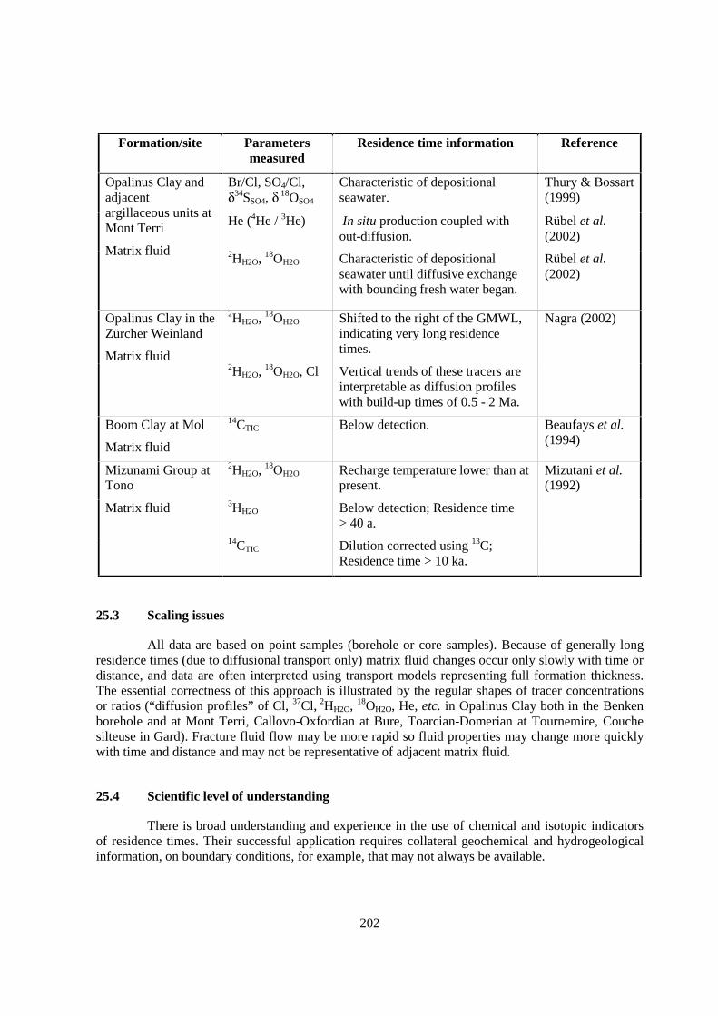
202
Formation/site Parametersmeasured
Residence time information Reference
Br/Cl, SO4/Cl,δ34SSO4, δ 18OSO4
Characteristic of depositionalseawater.
Thury & Bossart(1999)
He (4He / 3He) In situ production coupled without-diffusion.
Rübel et al.(2002)
Opalinus Clay andadjacentargillaceous units atMont Terri
Matrix fluid 2HH2O, 18OH2O Characteristic of depositionalseawater until diffusive exchangewith bounding fresh water began.
Rübel et al.(2002)
2HH2O, 18OH2O Shifted to the right of the GMWL,indicating very long residencetimes.
Nagra (2002)Opalinus Clay in theZürcher Weinland
Matrix fluid2HH2O, 18OH2O, Cl Vertical trends of these tracers are
interpretable as diffusion profileswith build-up times of 0.5 - 2 Ma.
Boom Clay at Mol
Matrix fluid
14CTIC Below detection. Beaufays et al.(1994)
2HH2O, 18OH2O Recharge temperature lower than atpresent.
Mizutani et al.(1992)
3HH2O Below detection; Residence time> 40 a.
Mizunami Group atTono
Matrix fluid
14CTIC Dilution corrected using 13C;Residence time > 10 ka.
25.3 Scaling issues
All data are based on point samples (borehole or core samples). Because of generally longresidence times (due to diffusional transport only) matrix fluid changes occur only slowly with time ordistance, and data are often interpreted using transport models representing full formation thickness.The essential correctness of this approach is illustrated by the regular shapes of tracer concentrationsor ratios (“diffusion profiles” of Cl, 37Cl, 2HH2O, 18OH2O, He, etc. in Opalinus Clay both in the Benkenborehole and at Mont Terri, Callovo-Oxfordian at Bure, Toarcian-Domerian at Tournemire, Couchesilteuse in Gard). Fracture fluid flow may be more rapid so fluid properties may change more quicklywith time and distance and may not be representative of adjacent matrix fluid.
25.4 Scientific level of understanding
There is broad understanding and experience in the use of chemical and isotopic indicatorsof residence times. Their successful application requires collateral geochemical and hydrogeologicalinformation, on boundary conditions, for example, that may not always be available.
203
Samples from fractures are likely to represent mixtures of fluids moving through various setsof fractures and between fracture and matrix pore fluids. Interpreting the age of mixtures from theirisotopic properties requires knowledge of the mixing ratios of component fluids. This may beavailable from chemical indicators of mixing or from concentrations of several environmentalradioisotopes of different half-lives, but is generally not possible.
25.5 Linked FEPs
Interpretation of residence times from isotope and chemical data requires consideration of:
FEP 17 Pore- and fracture water composition
FEP 23 Palaeo-hydrogeology of the host formation and of embedding units
FEP 24 Evolution of pore-fluid (water and gas) chemistry and mineralogy in the host formation andin embedding units
FEP 50 Past burial history
25.6 Level of understanding from a PA perspective and treatment in PA
Residence times from environmental isotope and solute composition data: (1) improvesystem understanding and (2) can be used to check the results of hydrodynamic models (whose resultsare then used in PA models).
25.7 Available reviews
There are no general reviews of residence time determinations in pore-waters of argillaceousformations. The applications of environmental isotopes in hydrogeology, including their use fordetermining residence times are described in the textbook by Clark & Fritz (1997). The discussion ofthe noble gas work at Mont Terri includes general background on the topic and additional references(Pearson et al., 2003, Annex 5). Proceedings of a NEA workshop on “Use of HydrogeochemicalInformation in Testing Ground-water Flow Models” provide, a broad summary and examples of thistopic (NEA, 1999b).
25.8 Planned work
The PHYMOL project, a study of the palaeo-hydrogeology of the Mol site, includesenvironmental isotope and noble gas analyses (Marivoet et al., 2000). It focuses mainly on thesurrounding aquifers.
25.9 Overall evaluation
Residence time determinations may not be possible in all systems. However, if they can befound, they provide additional information on retardation mechanisms and flow rates. Corroborationof residence times calculated using transport models adds confidence to flow modelling.

205
26. OXIDATION OF THE HOST ROCK (FEP B1.1)
26.1 Definition and generalities
During repository operation and following closure, transient oxidising conditions will beencountered from oxygen in air introduced during operations. They could have a large effect uponredox potential and pH and thus on solubility limitation of radionuclide concentrations and thecorrosion of the inner steel overpack, and could cause mineralogical changes in the host rock.Radiolysis of water in the immediate environment of waste packages (especially for high-level waste)can also produce species such as free hydrogen and oxygen influencing the redox potential. This FEPrefers only to mineralogical changes in the host rock. It is particularly relevant to pyrite-bearingformations, but the process can also affect organic material and other Fe+2-bearing minerals. This FEPis relevant to the affected field in connection with the EDZ.
Oxidation of pyrite may lead to the precipitation of new phases such as Fe(OH)3. Thesorption capacity of this phase, when freshly-precipitated, may be high and it can act to retard themovement of radionuclides through the affected field into the host formation (see FEP 21). Because allformations considered (except London Clay) contain carbonate, pH is buffered by calcite dissolution,and acidic conditions are not expected to develop at any time.
26.2 Site-specific experimental information
The argillaceous formations considered (except for the Boda Clay Formation) weredeposited under reducing conditions, which were preserved until the present. Solids controlling redoxconditions include sulphides (mainly pyrite), carbonates (siderite, ankerite) and organic matter.Whereas the partial oxidation of pyrite may occur rapidly in many of the formations (e.g. Boom Clay,Opalinus Clay, Oxford Clay, Toarcian-Domerian at Tournemire, Callovo-Oxfordian at Bure), effectson carbonates have not been reported, either because they do not occur or because they were notlooked at. Oxidation of organic matter appears to be very slow in comparison to the time scales ofexposure during repository operation. Acid waters associated with sulphide oxidation (known frommining dumps, acid mine drainage) do not occur in the formations considered here because they allcontain sufficient quantities of carbonate to buffer pH.
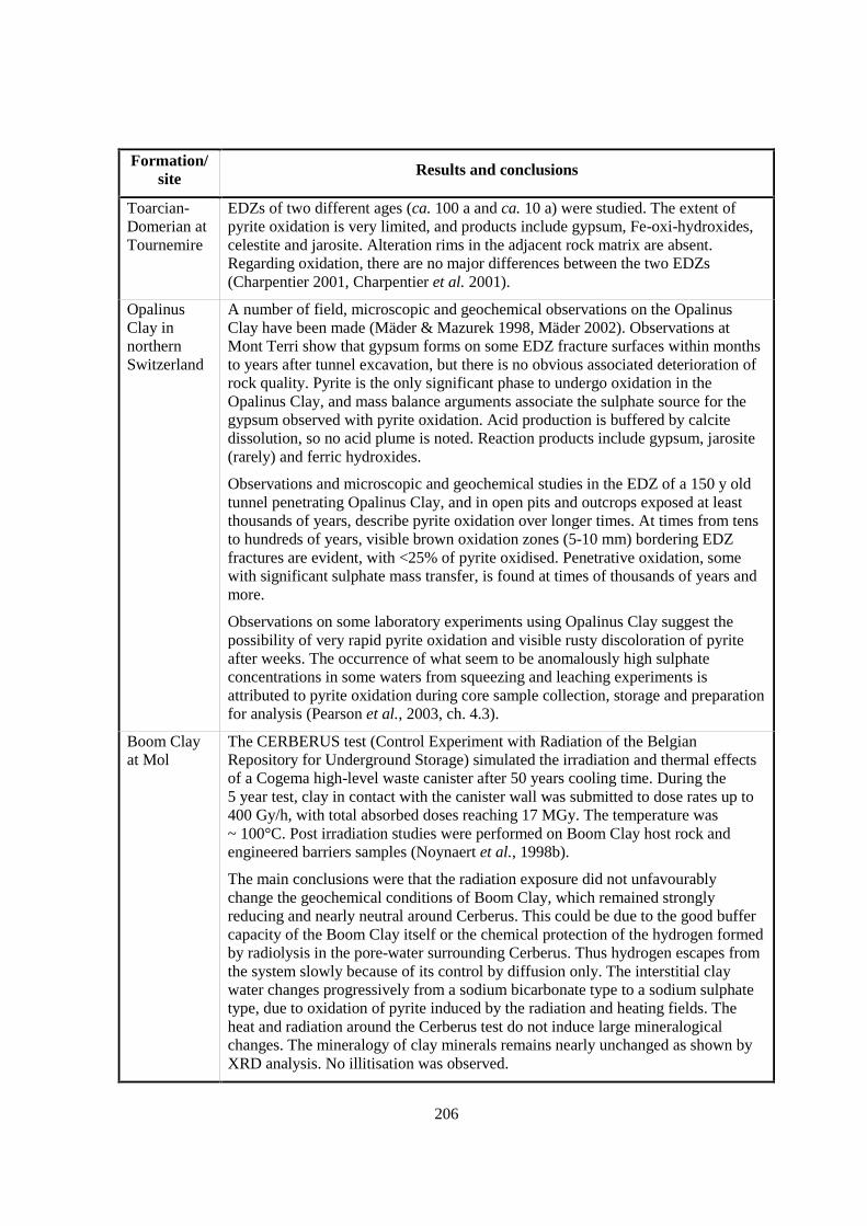
206
Formation/site Results and conclusions
Toarcian-Domerian atTournemire
EDZs of two different ages (ca. 100 a and ca. 10 a) were studied. The extent ofpyrite oxidation is very limited, and products include gypsum, Fe-oxi-hydroxides,celestite and jarosite. Alteration rims in the adjacent rock matrix are absent.Regarding oxidation, there are no major differences between the two EDZs(Charpentier 2001, Charpentier et al. 2001).
OpalinusClay innorthernSwitzerland
A number of field, microscopic and geochemical observations on the OpalinusClay have been made (Mäder & Mazurek 1998, Mäder 2002). Observations atMont Terri show that gypsum forms on some EDZ fracture surfaces within monthsto years after tunnel excavation, but there is no obvious associated deterioration ofrock quality. Pyrite is the only significant phase to undergo oxidation in theOpalinus Clay, and mass balance arguments associate the sulphate source for thegypsum observed with pyrite oxidation. Acid production is buffered by calcitedissolution, so no acid plume is noted. Reaction products include gypsum, jarosite(rarely) and ferric hydroxides.
Observations and microscopic and geochemical studies in the EDZ of a 150 y oldtunnel penetrating Opalinus Clay, and in open pits and outcrops exposed at leastthousands of years, describe pyrite oxidation over longer times. At times from tensto hundreds of years, visible brown oxidation zones (5-10 mm) bordering EDZfractures are evident, with <25% of pyrite oxidised. Penetrative oxidation, somewith significant sulphate mass transfer, is found at times of thousands of years andmore.
Observations on some laboratory experiments using Opalinus Clay suggest thepossibility of very rapid pyrite oxidation and visible rusty discoloration of pyriteafter weeks. The occurrence of what seem to be anomalously high sulphateconcentrations in some waters from squeezing and leaching experiments isattributed to pyrite oxidation during core sample collection, storage and preparationfor analysis (Pearson et al., 2003, ch. 4.3).
Boom Clayat Mol
The CERBERUS test (Control Experiment with Radiation of the BelgianRepository for Underground Storage) simulated the irradiation and thermal effectsof a Cogema high-level waste canister after 50 years cooling time. During the5 year test, clay in contact with the canister wall was submitted to dose rates up to400 Gy/h, with total absorbed doses reaching 17 MGy. The temperature was~ 100°C. Post irradiation studies were performed on Boom Clay host rock andengineered barriers samples (Noynaert et al., 1998b).
The main conclusions were that the radiation exposure did not unfavourablychange the geochemical conditions of Boom Clay, which remained stronglyreducing and nearly neutral around Cerberus. This could be due to the good buffercapacity of the Boom Clay itself or the chemical protection of the hydrogen formedby radiolysis in the pore-water surrounding Cerberus. Thus hydrogen escapes fromthe system slowly because of its control by diffusion only. The interstitial claywater changes progressively from a sodium bicarbonate type to a sodium sulphatetype, due to oxidation of pyrite induced by the radiation and heating fields. Theheat and radiation around the Cerberus test do not induce large mineralogicalchanges. The mineralogy of clay minerals remains nearly unchanged as shown byXRD analysis. No illitisation was observed.
207
Formation/site
Results and conclusions
Modelling has been done to evaluate the transient oxidising period after closure ofa hypothetical repository in the Boom Clay considering oxygen in the pore-waterand the bulk amount of iron consumed in the corrosion of the overpacks of vitrifiedhigh-level waste (Einchcomb & Grindrod 1995). Reaction with the carbon steelresulted in aerobic conditions with the corrosion rate limited by diffusive transportof oxygen towards the steel-bentonite interface, diffusion of the corrosion productsoutward from the buffer into the surrounding Boom Clay and reaction with ambientminerals (e.g. pyrite). The maximum duration of the anaerobic corrosion phase is11 years. Including diffusion into the surrounding Boom Clay and pyrite oxidationin the Boom Clay reduces this to as little as 3.1 years, depending on the rate ofpyrite oxidation.
26.3 Scaling issues
The distance scale of the Opalinus Clay observations is micrometres to metres and is appro-priate to PA. The time scale is weeks to hundreds of years and is appropriate for the operational phase.
26.4 Scientific level of understanding
Experience with the Opalinus and Boom Clays suggests that only pyrite is susceptible tooxidation over the time scales of interest. The chemistry of pyrite oxidation (and the possible oxidationof other reduced substances in these formation such as organic C, and Fe+2 or Mn+2 bearing minerals)is well understood in theory (Pearson et al., 2003, ch. 5.2.3, Rimstidt & Vaughan, 2003). The kineticsof pyrite oxidation are not well known, but constraints based on mass balance and oxygen diffusionrates are likely to be provide at least upper bounds on the extent of host rock oxidation.
26.5 Linked FEPs
FEP 14 Lithology, mineralogy of rocks and fracture infills
FEP 15 Natural organics, complexation
FEP 17 Pore- and fracture water composition
FEP 18 Dissolution / precipitation of solid phases
FEP 22 Thermodynamic and kinetic modelling data
FEP 27 Redox buffering capacity of the host rock
FEP 31 Thermal effects on mineral stability and pore-water composition
FEP 35 Size and structure of the EDZ
FEP 39 State of saturation of the EDZ and desiccation cracking
FEP 45 Gas dissolution and chemical interactions between gas and pore-water
FEP 49 Microbiological perturbations
FEP 52 Future changes in hydrochemistry of the host rock and of surrounding formations (e.g. due toout-diffusion, water-rock interactions, uplift)
208
26.6 Level of understanding from a PA perspective and treatment in PA
Observations in the Boom and Opalinus Clays suggest that while oxidation effects may beevident, they are spatially very restricted and modify neither the geochemical (redox) state nor thephysical properties of the formations. Thus, they are not included in PA analyses.
26.7 Available reviews
The influence of redox reactions on pore-water chemistry is covered in most textbooks ofaqueous geochemistry and by Pearson et al. (2003, ch. 5.2.3). The results of the radiation-effectsexperiment at Mol are given by Noynaert et al. (1998b), and the observations and conclusions on theOpalinus Clay and Palfris Formation by Mäder & Mazurek (1998) and Mäder (2002).
26.8 Planned work
Some oxidation of the Boom Clay has been observed during the excavation of theconnection gallery in 2002. A report is in preparation and is expected to be published in 2003.
26.9 Overall evaluation
Oxidation of the host rock induced by ventilation of the repository during the operationalphase or by irradiation is well understood and its importance to the PA of a given site or repositoryconfiguration can be determined in each case. This conclusion relies mainly on experimental, in situ,natural analogue and modelling data for the Boom Clay and Opalinus Clay.
209
27. REDOX BUFFERING CAPACITY OF THE HOST ROCK (FEP B1.1.1)
27.1 Definition and generalities
The redox buffer capacity of a system is a measure of its ability to resist changes in the redoxpotential. To be fully analogous to the widely used pH buffer capacity, the redox capacity would bedefined at a given Eh as the quantity of strong oxidant that, if added to 1 litre of sample, would raisethe Eh by one volt. The terms oxidative capacity (OXC) and reductive capacity (RDC) were definedby Scott & Morgan (1990):
OXC = � ni [Ox]i - � ni [Red]i = -RDC
where [Ox]i and [Red]i are the concentrations of individual oxidants and reductants and ni is thenumber of electrons transferred in each redox couple reaction. OXC and RDC values for a system aredetermined by titrating the system with a strong oxidant or reductant, respectively. Redox capacityvalues defined this way are similar to the total acid or base consuming capacity of a system.
The ability to resist oxidation depends on values of [Red]i, the concentration of substancessuch as sulphide and elemental sulphur, ammonium, organic carbon, and ferrous iron and otherreduced metals. The capacity to resist reduction depends values of [Ox]i, the concentrations ofsubstances such as dissolved oxygen, nitrate, sulphate, and ferric iron and other oxidised metals.Heron & Christensen (1994) define the total reduction capacity (TRC) of a formation based on itsconcentrations of species that can be readily oxidised (reduced manganese, reduced iron, oxidisableorganic carbon, reduced sulphur and reduced nitrogen) as:
TRC = 2 [Mn2+] + [Fe2+] + 4 [COOx] + 8 [S2-] + 7 [HS-] + 8 [NH4+]
which is an explicit formulation of Scott & Morgan’s expression above.
Substances oxidise at different oxidation potentials, and some substances can be oxidisedonly slowly. Thus the concept of an effective rather than a total redox capacity may be more useful.The effective redox capacity would include only those substances that would oxidise within the rangeof redox potentials of interest and at a rate commensurate with the time periods of interest.
27.2 Site-specific experimental information
The redox buffer capacity of the pore-water of Opalinus Clay at Mont Terri is negligible, butone kg pore-water in situ is associated with about 38 kg rock, so the redox capacity of the system isdominated by that of the rock. The total reduction capacity of the Opalinus Clay at Mont Terri rangesfrom 2.3 to 4.9 meq/g, based on chemical analyses of 7 core samples. Titration of one sample withK2Cr2O7 gave 4.8 meq/g, in good agreement with the values from the nearest analysed cores (Gaucheret al., 2003).
210
Mäder (2002) examined evidence of oxidation in exposures of Opalinus Clay and PalfrisFormation in tunnels, quarries and outcrops (see FEP 26). From these, he concludes that only pyriteoxidation is likely to occur over the time scale of repository operation. Thus, the effective reductioncapacity of the Opalinus Clay is due to pyrite alone and is only 0.1 to 0.2 meq/g, far lower than thetotal reduction capacity of the formation. The remaining reduction capacity is due to siderite andorganic C and, if available at all, would be felt only on very long time scales.
The redox buffer capacity of the Boom Clay at Mol is 2 meq/g.
27.3 Scaling issues
The redox capacity of host formations will not vary spatially, except for clusters of pyritecrystals, so scaling is not an issue.
27.4 Scientific level of understanding
The equilibrium chemistry of redox buffering is well understood. However, the rates atwhich various oxidation-buffering reactions may take place are not well known and may require site-specific evaluation.
27.5 Linked FEPs
FEP 14 Lithology, mineralogy of rocks and fracture infills
FEP 15 Natural organics, complexation
FEP 18 Dissolution/precipitation of solid phases
27.6 Level of understanding from a PA perspective and treatment in PA
Nagra concludes that canister corrosion products have a strong buffering capacity forradiolytic oxidants. In addition, pyrite and siderite in the bentonite could act as reductants (Johnson &Smith, 2000). For this reason Nagra does not take into account the redox buffering capacity of theOpalinus Clay in a safety assessment base case (only for what if scenarios).
In some other programmes, oxidation processes are treated indirectly by demonstrating thatthe depth penetration of the effects into the host formation is limited. For PA calculations, the lengthof the flow path is reduced by the size of the zone affected by oxidation.
27.7 Available reviews
Redox reactions in natural waters are discussed in any textbook of aqueous geochemistry.Stumm & Morgan (1996) provide particularly useful discussions of the potentials at which variousredox reactions occur and of the rates of redox reactions. Langmuir (1997), in addition, discussesdefinitions of redox capacities and the analogies between pH and Eh buffer capacities and strengths.

211
27.8 Planned work
None reported.
27.9 Overall evaluation
The importance of this FEP in PA is likely to be scenario dependent. It is not treatedexplicitly in most programmes.


213
28. EFFECTS OF REPOSITORY COMPONENTS ON PORE-WATER CHEMISTRYIN THE HOST ROCK (FEP B1.2)
28.1 Definition and generalities
A repository will contain a number of substances foreign to the host rock such as iron andother metals used for tunnel construction and stabilisation, and for waste handling and protection, aswell as bentonite buffer and backfill material. This FEP addresses the possible effects of this materialon the chemistry of the host rock. It is relevant to the affected field in connection with the EDZ. Notethat cements are excluded here and covered by FEP 29.
28.2 Site specific experimental information
None reported.
28.3 Scaling issues
None reported.
28.4 Scientific level of understanding
None reported.
28.5 Linked FEPs
FEP 14 Lithology, mineralogy of rocks and fracture infills
FEP 17 Pore- and fracture water composition
28.6 Level of understanding from a PA perspective and treatment in PA
None reported.
28.7 Available reviews
None reported.
214
28.8 Planned work
None reported.
28.9 Overall evaluation
This FEP is not considered explicitly by any organisation, but it is implicit in considerationsgiven other FEPs as discussed in Section II, Chapter 28.5. At least in diffusion-dominated systems,any effects would be expected to be spatially limited. Note that cement may also be present inrepositories. The effects of cement are included in FEP 29 and are excluded from this FEP.
215
29. INTERACTION OF HYPERALKALINE FLUIDS AND HOST ROCK (FEP B1.2.1)
29.1 Definition and generalities
This FEP addresses the influence of hyperalkaline (pH > 10.5) fluids of high Na, K and/orCa contents that may enter the formation (EDZ and beyond) and react with the host rock.
Hyperalkaline fluids could be produced by degradation of cement and concrete used in theconstruction of low and intermediate-level radioactive waste repositories for structural, encapsulationand backfilling purposes, or present in high level waste repositories as plugs or backfill. Theseinteractions, consisting of ion exchange and mineral dissolution and precipitation reactions, mayimpact the performance of the repository by potentially changing sorption, ground-water flow, andmatrix diffusion behaviour, inter alia. For repository safety assessment purposes, it is necessary toevaluate the type and magnitude of these interactions and their potential impact upon waste isolation.
The effects of this FEP on the performance of repositories in fractured rock may differ fromits effects on those in unfractured rock. In both cases, it could cause physical and chemical changes inthe bulk transport properties of the rock. In fractured rock, it could either increase or decrease fractureapertures, and, by dissolution or precipitation on fracture walls, could also affect solute exchangebetween matrix and fracture fluid and so modify the retardation expected from matrix diffusion.
29.2 Site-specific experimental information
Formation/site Results and conclusions
OpalinusClay at MontTerri
At Mont Terri, an in situ diffusion experiment, the CW-Experiment, was carriedout in a packed-off test interval of 3.5 l volume, at 10 m depth, heated to 35 °C.The interval was kept at 11 bar pressure, 1-2 bar above pore-water pressure. Thetest interval was connected to a reservoir and mass flow into rock was monitored.The fluid was a K-Na-Ca-OH solution, at pH = 13.2, saturated with Ca(OH)2,which was periodically replenished and analysed and has been circulated sinceMarch 2000. Overcoring of the test interval failed in October 2001.
Initial results show that buffering to pH 10 took place over 6 months, but thatsubsequent buffering is less efficient. Mass loss to the rock is about 2 g/day, and nosignificant decrease of the mass transfer rate was observed (Mäder et al. 2000). Nodetailed chemical interpretations have yet been made nor any specific modellingefforts, but some work is carried out in the framework of ECOCLAY II, an EU 5th
framework programme.
Experiments at the Mont Terri underground research laboratory indicate adiffusion-dominated regime lacking fracture-controlled or other preferentiallytransmissive features except for the EDZ.
216
Formation/site Results and conclusions
Boom Clayat Mol
SCK•CEN performed in situ experiments on the reaction at the interface betweenBoom Clay and concretes of different types (waste conditioning concrete andconstruction concrete). These experiments did not provide data on pore-waterchemistry changes but indicated that after 1 to 1.5 years of contact the mineralreaction zones both in the clay and in the concrete were limited to a very narrowzone of about 100 to 150 µm (Read et al., 2001b).
Laboratorystudies
Several laboratory studies with Opalinus Clay samples have been finalised or are inprogress (see Nagra 2002).
At the University of Bern, a high-pH infiltration experiment on a drill core sampleof Opalinus Clay was performed at 50 bar confining pressure, a 30 bar constanthead, at 30 °C, in a He atmosphere. Advective-dispersive piston flow was at a rateof 1/2 pore volume per week and decreased very slowly and steadily with timebefore dropping rapidly to zero after 14 months. The infiltrating fluid is a K-Na-Ca-OH type at pH=13.2, saturated with Ca(OH)2. The effluent was still buffered atpH = 9.6 after 14 months of infiltration (Adler et al., 2001, Nagra, 2002, ch. 7.5).
The results show that the high-pH plume infiltrating the rock is effectively bufferedfor the entire duration of the experiment by the combined process of displacementof Mg from the ion exchange complex, dolomite dissolution and precipitation ofMg-hydroxide phases. Significant precipitation of secondary calcite and illitic claycontinuously reduce the hydraulic conductivity and require the dissolution ofprimary silicates such as kaolinite and quartz. It is not straightforward to interpretthe observed final drop to zero-flow – either a completely impermeable zone withinthe rock matrix was produced or some phenomenon like a significant entry pressureto drive flow is implied.
High-pH diffusion and advection scoping experiments on samples of Opalinus Clayhave also been carried out using a K-Na-Ca-OH fluid of pH=13.2, saturated withCa(OH)2. Secondary minerals were detectable after 2-4 weeks at ambientconditions. A schematic time evolution of alteration sequences has been derived.Different parageneses were observed in diffusion and advection experiments. Thediffusive regime is a more efficient buffer and promotes zeolite formation while theadvective regime generates C-S-H type phases near the inlet. There is evidence forpreferential flow paths at a microscale, but overall front propagation ishomogeneous (Adler et al. 1999).
High-pH column experiments were carried out by BGS on pure minerals andcrushed rocks, including marl of the Palfris Formation. Flow-through columns wereused with Ca-OH and K-Na-Ca-OH solution at 70°C. Extensive formation ofC-S-H phases was noted as well as extensive clogging of flow paths within months.(Bateman et al., 1997, 2000).
In the framework of the ECOCLAY II project, laboratory experiments withbentonite/clay plugs are running and it is planned to start new experiments,including in situ tests, on the influence of concrete water on the pore-waterchemistry in the EDZ (e.g. partial pressure of CO2).
217
Formation/site Results and conclusions
Modelling Reactive transport modelling of high-pH fluid-rock interaction has been reportedbased on a simple fracture / rock matrix (dual porosity) system. The modelling usedparameters relevant to the Maqarin Natural Analogue Site, specifically for the rockmatrix. The role of dolomite dissolution to promote calcite precipitation is a crucialfactor in the sealing tendency of rock matrix adjacent to fracture pathways (Steefeland Lichtner 1994, 1998a, 1998b).
A reactive transport model was constructed for the core infiltration experimentusing an Opalinus Clay sample mentioned above, combining advection, dispersion,ion-exchange and mineral reactions (Adler 2001, Adler et al. 2001). It was possibleto match the observed effluent chemistry with a combination of independentlyconstrained parameters and a limited number of fit parameters. Some details of themodel were transferred to a pure diffusion case and are summarised in Nagra(2002, ch. 7.5).
IRSN, in collaboration with French School of Mines (ENSMP-CIG), developed theHITECH coupled code, which is suited to quantify hyperalkaline effects. Thechemical interactions between industrial materials and the host rock are modelledwith the reactive transport code HYTEC for time scales and geometriesrepresentative of disposal projects (De Windt et al., 2001a, b). The pH evolution, akey parameter in element mobility, is studied more specifically. It depends onseveral interdependent processes: i) diffusion of highly alkaline cement poresolution, ii) strong buffering related to major mineral transformations both in thecement and in the clay, and iii) cation exchange processes beyond the zone ofintense mineral transformations. In addition, precipitation of secondary mineralsmay lead to a partial or complete clogging of the pore space, thus limiting thepropagation of the high-pH plume. Research is ongoing to better assess the effectof geochemical processes on hydrogeology and on porosity changes, notably tounderstand the importance of kinetics and of fractures in the EDZ. Modelscombining radionuclide migration and cement-clay interactions are developed inparallel.

218
Formation/site Results and conclusions
Naturalanalogues:Maqarin andKusheimMatruk(Jordan)
Observations at the Maqarin Natural Analogue Project (Jordan) indicate that therock matrix adjacent to fracture-controlled pathways has been affected (mm to cm).Although the clay-mineral content is low, clay-mineral alteration is observed. ThepH is buffered at high values (12.5-12.8) along tens to hundreds of m of flowpathby C-S-H phases. Stages of alteration product assemblages are identified infractures and adjacent rock matrix, and secondary mineral assemblages arecomparable (Smellie et al. 1997, Alexander 1995a, b, Linklater et al. 1996,Linklater 1998, Smellie 1998).
Another important observation is that the consequence of the recurrent stages offracture reactivation (probably due to slumping of the steep hillslope and/or tectonicactivity) and subsequent percolation of hyperalkaline water is always fracturesealing by reaction products. This means that the rate of rock-matrix dissolution islower than the rate of precipitation of alteration products in the fractures. Thisobservation stands against some earlier model calculations which predict majordissolution and enhancement of fracture apertures. These calculations were madeusing unrealistic boundary conditions and also neglected precipitation in thefractures (Steefel & Lichtner 1994).
A new natural analogue study has begun in Kusheim Matruk, Central Jordan, on afossil hyperalkaline system adjacent to rocks with more clay minerals (10-30%)than at Maqarin. Preliminary studies document clay-mineral alteration, but onlyprogress reports are yet available (Smellie et al. 2000). One of the major problemsat this site is the difficulty to distinguish the effects of contact metamorphism andhyperalkaline alteration on clay minerals and other constituents. Veins andalterations possibly attributable to hyperalkaline effects are rare and occur onlywithin about half a metre away from the cement zone. The temperature at whichpotential interactions with hyperalkaline interactions occurred (possibly during thecooling stage of the metamorphic body?) is not constrained, and this limits theapplicability of this site as a natural analogue.
29.3 Scaling issues
The distance scale is mm to cm for laboratory experiments and mm to tens to hundreds of mfor natural analogues, which are relevant to PA. The time scale is too short in experiments butappropriate in natural analogues. Scaling of time is problematic due to large uncertainties in reactionrates at high-pH. Over long periods of time reaction rates are less crucial due to the approach to(dynamic) equilibrium.
29.4 Scientific level of understanding
The process is understood qualitatively in unfractured argillaceous rock, but quantitativeunderstanding is not sufficiently advanced yet to perform numerical predictions. The tendencies ofsystem evolution are understood sufficiently to allow for qualitative extrapolation, but quantitativeextrapolation is not yet reliable.
219
Modelling reactions of hyperalkaline fluids is made particularly uncertain by the poorlydefined physical properties, chemistry, and thermodynamic and kinetic constants of the variety ofsolid phases that may form (gels vs. crystalline solids, solid solutions).
29.5 Linked FEPs
FEP 3 Migration pathways, including heterogeneity and anatomy
FEP 6 Hydraulic properties of the host rock
FEP 8 Diffusivity
FEP 9 Connected matrix porosity
FEP 12 Colloid formation, transport and filtration
FEP 13 Flow-wetted surface and accessibility of matrix
FEP 14 Lithology, mineralogy of rocks and fracture infills
FEP 18 Dissolution/precipitation of solid phases
FEP 19 Solid solutions/co-precipitation
FEP 20 Ion exchange
FEP 21 Surface complexation
FEP 22 Thermodynamic and kinetic modelling data
FEP 35 Size and structure of the EDZ
FEP 38 Hydraulic properties of the EDZ
FEP 42 Self-sealing
29.6 Understanding from a PA perspective and treatment in PA
This FEP may be treated implicitly through the assessment of the radionuclide solubility andthe effective thickness of the argillaceous barrier. In some programmes, this FEP is treated solely byreducing the length of the flow path through the formation by the size of the zone affected byhyperalkaline effects. This size can be shown to be very limited in diffusion-dominated systems but isless straightforward to estimate in fractured, potentially advection-dominated formations.
29.7 Available reviews
General radwaste-related reviews include Smellie et al. (1997) and Alexander (1995b).
29.8 Planned work
Continuing and additional work is planned or ongoing both at Mol and at Mont Terri.
Work at Mol is carried out in part under ECOCLAY II in the EU 5th Framework programme.Experimental work includes: percolation and diffusion tests on cores, first with non- or poorly sorbedradionuclides and later with strongly sorbed elements; a test is expected to be performed in situ in the
220
underground research laboratory in order to evaluate the impact of this process under real conditions.A continuous influx of bicarbonate ions from the surrounding argillaceous formation mightsignificantly restrict the progression of the alkaline plume and limit its impact to the vicinity of therepository (diffusion of bicarbonate ions and neutralisation of the plume before it reaches the far field).Modelling work includes review and formulation of mineral precipitation and dissolution models,suggestion of alternative experimental designs; scoping calculations for percolation and diffusionexperiments (blind predictions) and evaluation and calibration of models based upon experimentaldata. The time scale should be around 4-5 years starting from 1999 (possible in situ test not included).An extension of the programme is highly probable.
Modelling work on Opalinus Clay continues in the framework of ECOCLAY II, It is plannedto extend the model of Adler (2001) to longer time scales assuming pure diffusion and rock propertiesderived from samples from the Benken borehole.
29.9 Overall evaluation
This FEP is relevant to PA, but to make a full PA analysis further information is required.The main open issue is the influence on migration parameters, but further knowledge of propertiesrequired for geochemical modelling is also necessary. Given the fact that highly sorbing phases areprecipitated due to the interaction of rock with hyperalkaline fluids, the overall effect on retardation ismost likely positive, even though difficult to quantify with confidence at the present stage.
221
30. ORGANICS FROM WASTE AND THEIR EFFECT ON TRANSPORT PROPERTIESOF THE HOST ROCK (FEP B1.2.2)
30.1 Definition and generalities
Organics from waste include different types of organic substances that are found inradioactive waste products and waste matrices. They may be leached or degraded both from materialin which radioactive waste is embedded (e.g. compacted and cemented cellulose-based waste, resins,plastics, organic decontamination agents) as well as from waste encapsulating matrix material (e.g.bitumen in bituminised waste products, modifiers that influence the rheological properties of mortarused to produce cemented waste). Organics from waste are formed either as unaltered leachingproducts or as radiolytical, chemical and/or microbial degradation products that are generatedaccording to waste- and repository-specific decomposition rates. Organics that originate from leachingor decomposition reactions, like those naturally present in the host rock and pore-water (FEP 15), mayadsorb onto solid phases, precipitate, form complexes with radionuclides, and/or migrate in complexedor uncomplexed form in the affected and far field. Note that the use of organic materials inconstruction materials of the repository galleries (e.g. modifiers in the mortar for the concrete linings)will also result in the release of organics with properties and fates similar to those originating from thewaste.
Potential effects of organics on transport through the host rock include
• Interactions with clay minerals (shrinkage, collapse, swelling), with resulting effects onhydraulic properties;
• Complexation of solutes on dissolved organic complexes or colloids, with effects onretention properties of the argillaceous formation.
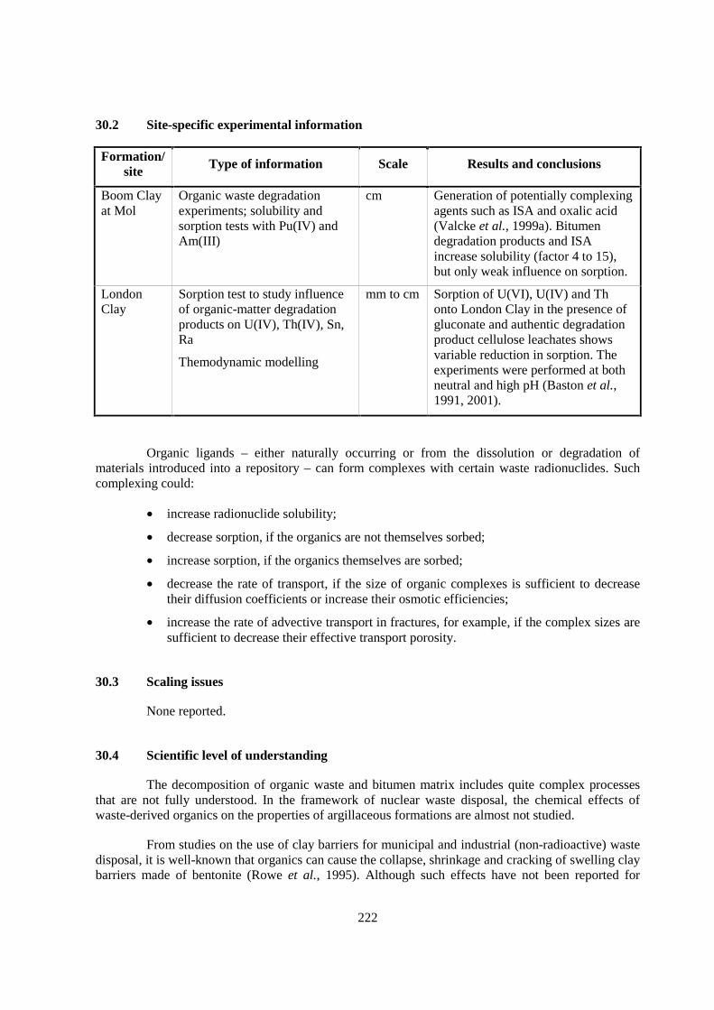
222
30.2 Site-specific experimental information
Formation/site Type of information Scale Results and conclusions
Boom Clayat Mol
Organic waste degradationexperiments; solubility andsorption tests with Pu(IV) andAm(III)
cm Generation of potentially complexingagents such as ISA and oxalic acid(Valcke et al., 1999a). Bitumendegradation products and ISAincrease solubility (factor 4 to 15),but only weak influence on sorption.
LondonClay
Sorption test to study influenceof organic-matter degradationproducts on U(IV), Th(IV), Sn,Ra
Themodynamic modelling
mm to cm Sorption of U(VI), U(IV) and Thonto London Clay in the presence ofgluconate and authentic degradationproduct cellulose leachates showsvariable reduction in sorption. Theexperiments were performed at bothneutral and high pH (Baston et al.,1991, 2001).
Organic ligands – either naturally occurring or from the dissolution or degradation ofmaterials introduced into a repository – can form complexes with certain waste radionuclides. Suchcomplexing could:
• increase radionuclide solubility;
• decrease sorption, if the organics are not themselves sorbed;
• increase sorption, if the organics themselves are sorbed;
• decrease the rate of transport, if the size of organic complexes is sufficient to decreasetheir diffusion coefficients or increase their osmotic efficiencies;
• increase the rate of advective transport in fractures, for example, if the complex sizes aresufficient to decrease their effective transport porosity.
30.3 Scaling issues
None reported.
30.4 Scientific level of understanding
The decomposition of organic waste and bitumen matrix includes quite complex processesthat are not fully understood. In the framework of nuclear waste disposal, the chemical effects ofwaste-derived organics on the properties of argillaceous formations are almost not studied.
From studies on the use of clay barriers for municipal and industrial (non-radioactive) wastedisposal, it is well-known that organics can cause the collapse, shrinkage and cracking of swelling claybarriers made of bentonite (Rowe et al., 1995). Although such effects have not been reported for
223
natural argillaceous formations, this point is included as a reminder that they should not be overlookedin site characterisation and PA activities.
30.5 Linked FEPs
FEP 12 Colloid formation, transport and filtration
FEP 14 Lithology, mineralogy of rocks and fracture infills
FEP 15 Natural organics, complexation
FEP 17 Pore- and fracture water composition
FEP 20 Ion exchange
FEP 21 Surface complexation
FEP 22 Thermodynamic and kinetic modelling data
FEP 41 Swelling
FEP 42 Self-sealing
30.6 Level of understanding from a PA perspective and treatment in PA
Effects on clay minerals are not expected to be relevant for high-level and most medium-level waste types. These waste types generally contain only small quantities of degradable organics,and measurements show that their influence is often weak. However, the foundation for this judgementis weak and should be improved. The principles of organic complexation are generally wellunderstood and the effect of pure and/or synthetic organics is rather well known. Complexation withnatural organics or organics from degradation products is however much more complex. Often there isonly little knowledge about the influence of the organics on sorption and thus mobility of theradionuclides.
Currently understanding of the influence on retardation allows only conservative treatment inPA by assuming higher solubility and lower sorption for radionuclides that are known to be easilycomplexed. Sensitivity and uncertainty studies are performed to assess the potential importance. Thereis little understanding of effects on hydraulic properties, and they are not considered in PA.
The relevance of this FEP varies among different disposal concepts, waste forms and thepresence and nature of organics therein.
30.7 Available reviews
None reported.
30.8 Planned work
At SCK•CEN, further work on organics from bitumenised medium-level waste is foreseen.Further experimental work connected with PA concerning the influence of organics on solubility andsorption (mobility) of radionuclides is planned.

224
30.9 Overall evaluation
This FEP is poorly studied. Only wastes containing substantial quantities of organics such ascellulose or waste embedded in bitumen are expected to have significant effects. Current knowledgeallows only conservative treatment in PA. Some organisations consider this FEP to be irrelevant,others have little information and are not able to assess the relevance. Of particular interest is thepotential increase of solubility and mobility of some radionuclides. Experimental studies carried outtill now indicate only a very moderate effects. For special waste types with large quantities oforganics, further studies are planned to substantiate this conclusion. Effects of organics on hydraulicproperties are expected to be negligible and are not considered.
225
31. THERMAL EFFECTS ON MINERAL STABILITYAND PORE-WATER COMPOSITION (FEP B2.1)
31.1 Definition and generalities
The equilibrium positions of chemical reactions vary with temperature, as do reaction rates.Rising temperatures increase the solubility of most solids, decrease the solubilities of most gases andincrease most reaction rates. Results of changing temperature could be modification of the chemistryof pore-water and/or of formation mineralogy. Thermal effects on clay minerals and organic materialsare most prominent in argillaceous formations.
This FEP is relevant to the region in which thermal anomalies from the repository extend,although it will be most relevant to the region of highest temperatures in the affected field.
31.2 Site-specific experimental information
The influence of past thermal effects on a given formation can be evaluated from the identityand crystallinity of clay minerals, properties of organic material such as its vitrinite reflectance, andthe identity, chemistry, fluid inclusion properties and stable isotopic properties of secondary minerals,particularly those in fractures and veins.
Intense thermal effects can be evaluated using argillaceous rocks found near volcanicintrusions as natural analogues (Miller et al., 2000). According to Bouchet et al. (1999) and Pellegriniet al. (1999a, b, c), the findings at different analogue sites suggest a temperature of ca. 100°C belowwhich the modifications to the host formation are expected to be minor.
In the Spanish Reference Clay in a Tertiary basin, dehydration of rock-forming gypsum isexpected as a consequence of the thermal pulse.
Nagra (2002) explicitly examined thermal effects in the Opalinus Clay. For the plannedhigh-level waste repository in the Zürcher Weinland, the development of the thermal pulse emanatingfrom the heat-producing waste was quantified by Johnson et al. (2001). Over a period of max. 1 000 y,temperature at the interface of bentonite and Opalinus Clay will exceed 80°C with a maximum of95°C in the (worst) case of MOX/UO2 canisters. These temperatures are only slightly higher than themaximum temperature of ca. 85°C experienced by the formation during maximum burial (seeFEP 50). At the time when the thermal pulse will occur, the repository system will not be fullysaturated, so that water is expected to flow from the formation into the engineered barrier system (andnot vice versa). The following processes related to the thermal pulse were taken into account (Nagra,2002, Mazurek, 2002):
• thermal maturation of organic matter;
• illitisation of the illite/smectite mixed-layer phase;

226
• acceleration of oxidation reactions (see FEP 26);
• changes in pore-water chemistry.
The first three processes involve kinetics, the fourth process can be described by equilibriumthermodynamics and is reversible.
Given the short time scales involved and the small difference to temperatures alreadyexperienced by Opalinus Clay during burial, thermal effects on organic matter and clay minerals wereshown to be negligible. Pyrite oxidation in Opalinus Clay is most likely limited by the rate of oxygendiffusion into the matrix (Mäder & Mazurek, 1998). The increased diffusion coefficient at 95°C resultsin an increase of oxidation rate by a factor 4, which is also negligible vis-à-vis the limited magnitudeof this reaction (see also FEP 26). The pore-water chemistry will change towards higher pH (ca. 0.6units) and higher PCO2 (less than 1 log unit). The water type remains the same, with only slight changesin ion concentrations. The only relevant mineral reaction is calcite dissolution, with negligible effectson porosity.
It was concluded that all thermal effects, even on the interface to the bentonite, arenegligible. This finding from the Opalinus Clay may not be easily transferable to other formations, inspecific to those which experienced substantially lower temperatures during maximum burial, such asthe Boom Clay and the Spanish Reference Clay, or the Callovo-Oxfordian at Bure.
31.3 Scaling issues
None reported.
31.4 Scientific level of understanding
The processes by which changing thermal conditions will affect mineral and solutionproperties are well understood and can be evaluated by geochemical modelling. For such modelling tobe reliable requires data on the temperature-dependence of mineral transformations and water-rockinteractions. It also requires the assumption of equilibrium or data for modelling reaction kinetics.However, there are uncertainties in thermodynamic and kinetic data for many reactions (FEP 22).Chief among these reactions are those for transformations among clay minerals (Mazurek 2002).
31.5 Linked FEPs
FEP 14 Lithology, mineralogy of rocks and fracture infills
FEP 15 Natural organics, complexation
FEP 17 Pore- and fracture water composition
FEP 18 Dissolution / precipitation of solid phases
FEP 20 Ion exchange
FEP 21 Surface complexation
FEP 22 Thermodynamic and kinetic modelling data
FEP 32 Thermal rock properties
227
FEP 50 Past burial history
31.6 Level of understanding from a PA perspective and treatment in PA
Processes referred to in this FEP are not explicitly included in PA models because they arethought not to be important. However, the effects of changing thermal conditions should be evaluatedto be certain their effects on the retardation and other properties of the host rock are not sufficient tochange the output of the PA modelling by any significant amount. It should be noticed that in mostrecent repository concepts the maximum temperature that is expected to occur in the affected field isless than 100°C.
31.7 Available reviews
An example of consideration of thermal effects as background for a PA can be found inNagra (2002).
31.8 Planned work
None reported.
31.9 Overall evaluation
The processes described in this FEP are not likely to have a significant effect on host-rockbehaviour. A brief examination making use of the expected thermal regime can confirm this for agiven site.

229
32. THERMAL ROCK PROPERTIES (FEP B2.2)
32.1 Definition and generalities
The most important thermal rock properties include:
(1) Thermal conductivity K [W ∗ m-1 ∗ °C-1]
(2) Heat capacity C [ J ∗ kg-1 ∗ °C-1]
(3) Specific heat Cp [W ∗ s ∗ kg-1 ∗ °C-1]
(4) Coefficient of linear thermal expansion ε t [°C-1]
(1) and (3) yields:
(5) Thermal diffusivity k = K /(ρ ∗ Cp) [m2/s] with ρ = rock density
K, ε t and k may be anisotropic, predominantly depending on the rock-specific degree of bedding(parameters measured ⊥ [normal] and // [parallel] to bedding).
32.2 Site-specific experimental information
Formation/site Results and conclusions
Callovo-Oxfordian atBure
From laboratory tests:
K⊥ = 1.65 [W ∗ m-1 ∗ °C-1]; K// / K⊥ = 1.27; K decreases significantly withdecreasing degree of saturation.
C = 756 [J ∗ kg-1 ∗ °C-1] at 20 °C with C = f (temperature).
Toarcian-Domerian atTournemire(mainly notsite-specificwork by IRSN)
• Determination of the classical parameters K, C.
• Laboratory investigations on thermal and hydraulic diffusion in argillaceousrocks under thermal loading. Evolution of thermal conductivity as a f(T).Thermal properties of argillaceous rocks under thermal-hydraulic-mechanical strain (Djeran 1991).
• Laboratory investigations on possible creep of different plastic clays underthermal strain (Bonne et al. 1991, Norotte et al. 1992; Boisson et al. 1993).
SpanishReference Clayin a Tertiarybasin
K = 1.06 [W ∗ m-1 ∗ °C-1]; C = 1117 [J ∗ kg-1 ∗ °C-1];
k = 4.73 x 10⁻⁷ [m2/s] (Enresa 1999).
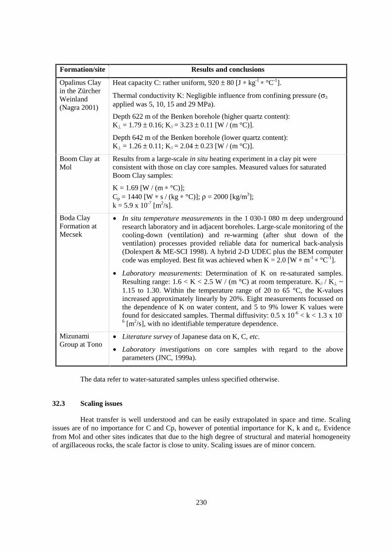
230
Formation/site Results and conclusions
Opalinus Clayin the ZürcherWeinland(Nagra 2001)
Heat capacity C: rather uniform, 920 ± 80 [J ∗ kg-1 ∗ °C-1].
Thermal conductivity K: Negligible influence from confining pressure (σ3
applied was 5, 10, 15 and 29 MPa).
Depth 622 m of the Benken borehole (higher quartz content):K⊥ = 1.79 ± 0.16; K// = 3.23 ± 0.11 [W / (m °C)].
Depth 642 m of the Benken borehole (lower quartz content):K⊥ = 1.26 ± 0.11; K// = 2.04 ± 0.23 [W / (m °C)].
Boom Clay atMol
Results from a large-scale in situ heating experiment in a clay pit wereconsistent with those on clay core samples. Measured values for saturatedBoom Clay samples:
K = 1.69 [W / (m ∗ °C)];Cp = 1440 [W ∗ s / (kg ∗ °C)]; ρ = 2000 [kg/m3];k = 5.9 x 10⁻⁷ [m2/s].
Boda ClayFormation atMecsek
• In situ temperature measurements in the 1 030-1 080 m deep undergroundresearch laboratory and in adjacent boreholes. Large-scale monitoring of thecooling-down (ventilation) and re-warming (after shut down of theventilation) processes provided reliable data for numerical back-analysis(Dolexpert & ME-SCI 1998). A hybrid 2-D UDEC plus the BEM computercode was employed. Best fit was achieved when K = 2.0 [W ∗ m-1 ∗ °C-1].
• Laboratory measurements: Determination of K on re-saturated samples.Resulting range: 1.6 < K < 2.5 W / (m °C) at room temperature. K// / K⊥ ~1.15 to 1.30. Within the temperature range of 20 to 65 °C, the K-valuesincreased approximately linearly by 20%. Eight measurements focussed onthe dependence of K on water content, and 5 to 9% lower K values werefound for desiccated samples. Thermal diffusivity: 0.5 x 10⁻⁶ < k < 1.3 x 10-
6 [m2/s], with no identifiable temperature dependence.
MizunamiGroup at Tono
• Literature survey of Japanese data on K, C, etc.
• Laboratory investigations on core samples with regard to the aboveparameters (JNC, 1999a).
The data refer to water-saturated samples unless specified otherwise.
32.3 Scaling issues
Heat transfer is well understood and can be easily extrapolated in space and time. Scalingissues are of no importance for C and Cp, however of potential importance for K, k and εt. Evidencefrom Mol and other sites indicates that due to the high degree of structural and material homogeneityof argillaceous rocks, the scale factor is close to unity. Scaling issues are of minor concern.
231
32.4 Scientific level of understanding
The scientific level of understanding is very good. The mechanism of heat transport relevantfor argillaceous rock with very low hydraulic conductivity (< 10-13 m/s) is predominantly conduction.Heat convection due to fluid flow and radiation are mechanisms of minor or no importance. Incomparison with the mechanical and hydraulic properties of the rock, the natural scatter of the thermalrock properties is rather small.
32.5 Linked FEPs
FEP 9 Connected matrix porosity
FEP 14 Lithology, mineralogy of rocks and fracture infills
32.6 Level of understanding from a PA perspective and treatment in PA
This FEP is well understood with regard to processes and parameters for quantitativetreatment in PA. The most important application of thermal parameters is the heat produced by high-level waste, and is generally considered as an important factor in the safety evaluation.
Modelling of heat transport in argillaceous rocks is based on the mechanism of conduction(application of heat transfer equations). Radiation and convection are neglected. Heat capacity andconductivity are used as input parameters for the calculation of the temperature evolution of arepository. The data have a direct implication on the layout of the repository (Johnson et al., 2001).Within the conceptual model used for the Spanish PA, it is assumed that the thermal properties of theengineered barrier system (bentonite backfill) depend on the water content. For the host rock,however, thermal properties are assumed to be constant in time and independent of the water contentand temperature (Enresa, 1999). SCK•CEN conclude that the impact of heat is rather limited as long asthe container or overpack will prevent that ground water will come into contact with the waste duringthe thermal phase of the repository.
32.7 Available reviews
Site specific reviews: Spanish Reference Clay: Enresa (1999); Callovo-Oxfordian at Bure:AGEM (1998); Boom Clay: Put & Henrion (1992).
32.8 Planned work
Callovo-Oxfordian at Bure: Some heating tests aiming at characterising the THM responseof the host rock will be carried out in the underground research laboratory. Site-specific thermalproperties will be used in predictive modelling of the temperature distribution. The parameters will bechecked by comparison of the numerical predictions with in situ measurements.
32.9 Overall evaluation
The temperature of the host rock formation in space and time depends predominantly on thespecific thermal properties of the rock and on the heat generation rate of the high-level waste in the

232
emplacement tunnel. The mechanical, hydraulic and chemical effects in the host rock which areassociated with temporarily increased temperatures are important for the evaluation of the repositorysystem particularly in the affected field with regard to the behaviour of the EDZ and the engineeredbarrier systems.
The site-specific thermal rock parameters have to be determined in line with establishedtesting procedures, either in the laboratory and/or in situ. They represent indispensable inputparameters for the analytical sections of a PA.
It is generally felt that the principal features of this FEP are sufficiently well understood. Atthis point in time no further work seems to be justified to enhance the scientific understanding of thisFEP beyond current levels.
233
33. THERMALLY INDUCED CONSOLIDATION OF HOST ROCK (FEP B2.3)
33.1 Definition and generalities
The term “thermally-induced consolidation” relates on one hand to a radioactive heat sourcewhich is located in the backfilled emplacement tunnel (see also FEP 40) and, on the other hand, to atime-dependent solid-water interaction of cohesive materials (see also FEP 58). The time span overwhich the waste-derived heat pulse will act is of the order of some 1 000 to 10 000 years.
Subjecting a saturated cohesive material, such as a saturated argillaceous rock, to atemperature increase leads to a consolidation process which is similar to conventional mechanicalconsolidation (thermal stress instead of mechanical stress; Paaswell, 1967; Virdi and Keedwell, 1988).Initial thermal loading leads to a significant, irreversible consolidation which is manifested in adecrease of the void ratio (Campanella and Mitchell, 1968; Plum and Esrig, 1969; Habibagahi, 1973;Demars and Charles, 1982). Further temperature cycles yield comparatively minor, mostly reversibledeformations as long as the maximal temperature of the first heat cycle is not exceeded. Thermalconsolidation is a broadly measured phenomenon. Its effect is, however, more marked forreconstituted materials (Towhata and Kuntiwattanakul, 1994; Tanaka et al., 1997) than for naturalrocks.
The reduction of the strength of intact rock and the associated internal, irreversibledeformation of the rock can lead to secondary consolidation effects. In case of a temperature decreasewith its associated shrinkage of the intact rock and of the pore-water, suction will develop. This willlead to an adsorption of water without any significant non-elastic reverse deformations within theintact rock matrix.

234
33.2 Site-specific experimental information
Formation/site Results and conclusions
Opalinus Clayin the ZürcherWeinland
Numerical modelling studies (Johnson et al., 2001) and synoptic studies (Nagra,2002). The consequences of the waste-derived heat pulse are very limited.
Boom Clay atMol
In situ tests: CACTUS (Trentesaux 1997) and ATLAS (De Bruyn and Labat,1998).
Laboratory tests: Drained heating before submitting Boom Clay samples totriaxial CIU tests have been performed at two temperature levels (50 and 80°C).In both cases, the thermally-induced consolidation remains rather limited (deBruyn 1999).
Boda ClayFormation atMecsek
In situ tests: No irreversible thermally-induced consolidation effects wereobserved.
Of particular importance for the long-term development of a consolidation process is thechange of permeability of the host rock. In thermal loading, permeability can principally be affectedby two processes (Nagra, 2002):
(1) When considering the process of thermal consolidation as a deformation of a poro-elasticmaterial, the relevant processes are the reduction of porosity and of permeability (Kozeny-Carman relationship; de Marsily, 1986). Beyond the irreversible changes due to first thermalloading, the net effects of a second thermal cycle (of comparable or lower intensity) onpermeability remain negligible. For the formations considered, the first thermal loadingoccurred in the course of the geological burial.
(2) The second process of relevance is the possible formation, or reactivation, of discretediscontinuities or cracks due to additional thermal stress and increased pore-water pressure.A reduction of the effective stress (e.g. by an increase of the pore-water pressure) increasesthe over-consolidation ratio of the argillaceous material, resulting in dilatant deformation andfracturing (Horseman, 2001; see also FEP 42). Once the dilatant discontinuities are formedor reactivated, the permeability along them is increased, at least temporarily, by some ordersof magnitude. This, in turn, assists in a subsequent reduction of the pore-water pressure andin associated reductions of the over-consolidation ratio, crack opening and permeability(Blümling et al., 2001). Renewed mechanical loading and swelling then initiate a self-sealingprocess (Horseman, 2001) which will be further enhanced by the reduction of the pore-waterpressure during or after the cooling phase. A precondition for fracturing to occur is that theeffective stress level infringes the limiting strength conditions. At least in the case of theOpalinus Clay in the Zürcher Weinland, this is not the case (Nagra, 2002).
33.3 Scaling issues
With regard to the specification of the thermal pulse in space and time, no up- ordownscaling is required. However, upscaling of the parameters describing the EDZ may be required(FEPs 37 and 40).

235
33.4 Scientific level of understanding
Current scientific understanding relies on combined knowledge of both the consolidationprocess proper and the effects of the relevant physical parameters. This knowledge is supported by alimited number of purpose-designed tests which have been carried out to date.
33.5 Linked FEPs
FEP 14 Lithology, mineralogy of rocks and fracture infills
FEP 32 Thermal rock properties
FEP 37 Geomechanical rock properties
FEP 50 Past burial history
33.6 Level of understanding from a PA perspective and treatment in PA
This FEP is insensitive to PA models and generally not explicitly taken into account. Itseems that the influence of this FEP remains limited.
33.7 Available reviews
None reported.
33.8 Planned work
None reported.
33.9 Overall evaluation
The understanding of this FEP relies on combined general knowledge of the consolidationprocess proper and on the effects of the physical parameters associated with the consolidation and heatdissipation processes in argillaceous materials. Only a very limited number of purpose-designed testswere carried out to date. Irrespectively of this, there is unanimous agreement that the influence of thisFEP remains limited and it is seen as insensitive to PA models.


237
34. GEOMECHANICAL STABILITY (FEP B3.1)
34.1 Definition and generalities
In geotechnical engineering, the term “stability” is associated with the absence of large-scalefailures or of excessive deformations which are detrimental to the function and safety of theengineered structure. In context with this FEP the term is associated mainly with the stability of theunderground excavations of a repository and, to a minor degree, with the stability of boreholes inargillaceous rocks. The considerations on the stability of underground openings include the groundsupport system, if required. This FEP is a very important system component for the design and theoperational phase of a repository. The geomechanical stability of the excavated underground openingsis explicitly considered within the engineering analysis. Potential stability problems of the galleriesafter the emplacement of the waste and backfilling are considered to be irrelevant and are notaddressed by this FEP. Furthermore, this FEP is neither associated with the global stability of therepository as a whole nor with the stability of geological host formation (e.g. the re-activation of ageological fault by increased pore-water pressures).
34.2 Site-specific experimental information
Formation/ site Results and conclusions
Callovo-Oxfordian atBure
In situ at depths between 400 and 500 m: Observation of borehole breakouts andovalisation once the boreholes were passing through argillaceous layers.
Toarcian-Domerian atTournemire
In situ: Monitoring during and after the excavation of two drifts, analysis ofresults and modelling of the mechanical response of the rock with time due tosequential excavation (Boisson, 2002).
SpanishReference Clayin a Tertiarybasin
The numerical code FLAC was employed in evaluating the effects of a tunnel onto the host rock in the following two formations: (1) In the Spanish ReferenceClay (DM Iberia 1994) and (2) in the Opalinus Clay at Mont Terri (Velasco &Pedraza, 1997).
Boom Clay atMol
Excavation of the Boom Clay at industrial scale has been demonstrated at a depthof 230 m. A convergence of about 9 cm (including about 4 cm of convergenceahead of the excavated front) is considered as acceptable for the long termperformance of the repository. Excavation leads to fracturing of the clay body.Rigid lining is required to ensure the stability of the tunnel wall and to limitdelayed convergence.
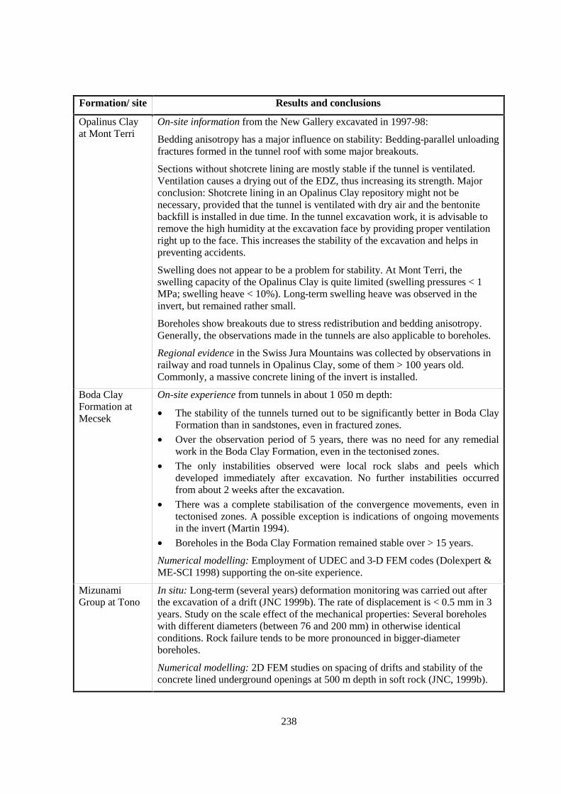
238
Formation/ site Results and conclusions
Opalinus Clayat Mont Terri
On-site information from the New Gallery excavated in 1997-98:
Bedding anisotropy has a major influence on stability: Bedding-parallel unloadingfractures formed in the tunnel roof with some major breakouts.
Sections without shotcrete lining are mostly stable if the tunnel is ventilated.Ventilation causes a drying out of the EDZ, thus increasing its strength. Majorconclusion: Shotcrete lining in an Opalinus Clay repository might not benecessary, provided that the tunnel is ventilated with dry air and the bentonitebackfill is installed in due time. In the tunnel excavation work, it is advisable toremove the high humidity at the excavation face by providing proper ventilationright up to the face. This increases the stability of the excavation and helps inpreventing accidents.
Swelling does not appear to be a problem for stability. At Mont Terri, theswelling capacity of the Opalinus Clay is quite limited (swelling pressures < 1MPa; swelling heave < 10%). Long-term swelling heave was observed in theinvert, but remained rather small.
Boreholes show breakouts due to stress redistribution and bedding anisotropy.Generally, the observations made in the tunnels are also applicable to boreholes.
Regional evidence in the Swiss Jura Mountains was collected by observations inrailway and road tunnels in Opalinus Clay, some of them > 100 years old.Commonly, a massive concrete lining of the invert is installed.
Boda ClayFormation atMecsek
On-site experience from tunnels in about 1 050 m depth:
• The stability of the tunnels turned out to be significantly better in Boda ClayFormation than in sandstones, even in fractured zones.
• Over the observation period of 5 years, there was no need for any remedialwork in the Boda Clay Formation, even in the tectonised zones.
• The only instabilities observed were local rock slabs and peels whichdeveloped immediately after excavation. No further instabilities occurredfrom about 2 weeks after the excavation.
• There was a complete stabilisation of the convergence movements, even intectonised zones. A possible exception is indications of ongoing movementsin the invert (Martin 1994).
• Boreholes in the Boda Clay Formation remained stable over > 15 years.
Numerical modelling: Employment of UDEC and 3-D FEM codes (Dolexpert &ME-SCI 1998) supporting the on-site experience.
MizunamiGroup at Tono
In situ: Long-term (several years) deformation monitoring was carried out afterthe excavation of a drift (JNC 1999b). The rate of displacement is < 0.5 mm in 3years. Study on the scale effect of the mechanical properties: Several boreholeswith different diameters (between 76 and 200 mm) in otherwise identicalconditions. Rock failure tends to be more pronounced in bigger-diameterboreholes.
Numerical modelling: 2D FEM studies on spacing of drifts and stability of theconcrete lined underground openings at 500 m depth in soft rock (JNC, 1999b).

239
34.3 Scaling issues
Underground research laboratories and repository emplacement tunnels have similardimensions, so no spatial upscaling is required. The observation time in underground researchlaboratories and tunnels extends over a time span of up to 100 years. The stability of the emplacementtunnels must be guaranteed over a time span of several years, so no upscaling in terms of time isrequired either. The same applies to other underground structures such as access tunnels, pilot and testfacilities. Separate considerations might be necessary for underground storage tunnels for retrievablewaste.
34.4 Scientific level of understanding
The level of understanding of this FEP is excellent. Reference can be made to a large bodyof knowledge from underground construction work in civil and mining engineering.
34.5 Linked FEPs
FEP 14 Lithology, mineralogy of rocks and fracture infills
FEP 35 Size and structure of the EDZ
FEP 37 Geomechanical rock properties
FEP 39 State of saturation of the EDZ and desiccation cracking
FEP 38 Hydraulic properties of the EDZ
FEP 41 Swelling
FEP 42 Self-sealing
FEP 50 Past burial history
FEP 55 Present-day stress regime
34.6 Level of understanding from a PA perspective and treatment in PA
This FEP constitutes a very important system component for the design and for the earlyphase of a repository. It is critical for the functionality and safety of the technical operations. It is of nofurther concern after backfilling of the emplacement tunnel. Thus while it is important for the safetyconcept and for the operational phase, it is of no concern for PA. Generally, the level of understandingis considered to be sufficient (for short-term stability of up to some 10 years). However, this is notnecessarily the case for the retrievability option, in which the geomechanical stability is of concernover a larger time scale.
The geomechanical stability of the excavated underground openings is explicitly consideredwithin the engineering analysis of the repository. The methodology is in line with establishedengineering tunnel design procedures. The design includes the selection and dimensioning of thetunnel support system, if required.
240
34.7 Available reviews
Callovo-Oxfordian at Bure: AGEM (1998); Toarcian-Domerian at Tournemire: Boisson(2002).
34.8 Planned work
Formation/site Planned activities
Callovo-Oxfordian atBure
Vertical and horizontal mine-by tests with special emphasis on theinfluence of humidity on creep and rock strength. Predictive modelling ofthe mine-by tests; comparison of performance versus prediction; aposteriori modelling.
Toarcian-Domerian atTournemire
Further laboratory mechanical tests; continuation of in situ measuringprogrammes; improvement of the rheological law for argillaceous rocks;modelling and validation.
Opalinus Clay at MontTerri
Continuous modelling with numerical codes such as CODE_BRIGHT ofsome of the Mont Terri experiments; in the near future: EB and VEExperiments (Velasco & Pedraza, 1997).
Boom Clay at Mol Fracturing around the excavation will be studied within the scope of theSELFRAC project.
Boda Clay Formationat Mecsek
Modelling programme with the existing field data.
34.9 Overall evaluation
This FEP is an important feature in the early phases of a repository. It is critical for thefunctionality and safety of the technical operations in the underground excavations throughoutconstruction and operation. The level of understanding is excellent. Reference can be made to a largebody of knowledge from underground construction work in civil and mining engineering. The studiesrequired for PA are in line with established engineering tunnel design methods. The design includesthe selection and dimensioning of the tunnel support system, if required.
In the case of a repository with the option for a retrieval of the waste, the long-termgeomechanical stability of the underground excavations is less well understood and may need furtherattention.
241
35. SIZE AND STRUCTURE OF THE EDZ (FEP B3.2)
35.1 Definition and generalities
Underground excavation leads to a stress redistribution within the rock close to theexcavated opening (tunnel, shaft, borehole). Depending on the excavation parameters (support type,excavation method and rate, size and shape of the opening, stress level, drilling fluid) and on the rockproperties and their anisotropy, shear or tensile fractures (i.e. faults and joints) may develop in theadjacent rock. The EDZ (excavation-disturbed zone) includes not only the zone containing inducedfractures (also termed “plastic zone”) but also the distal part, which is characterised by elasticdeformations due to excavation-induced stress changes (also termed “elastic zone”).
Generally speaking, the more indurated the rock, the greater the likelihood of generatingEDZ fractures. Over the long time period considered in PA, the counter effect (i.e. self-sealing, FEP42) must be accounted for.
35.2 Site-specific experimental information
Formation/site Results and conclusions
Callovo-Oxfordian atBure
Ovalisation and failure were observed in investigation boreholes penetrating thetarget formation. Based on numeric models for an unsupported gallery, the size ofthe EDZ was shown to extend from the excavated surface into the rock by about 75%of the excavation radius.
Toarcian-Domerian atTournemire
Relevant information can be found in Boisson (2002) and Alheid et al. (1999).
The underground research laboratory consists of a 110 years old tunnel (cross-section area 4.6 m x 5.7 m) and two galleries built in 1996, each 30 m long and witha circular cross-sectional area of 12 m2. 500 days after the construction of the latter,convergence was max. 5 mm in the eastern, weakly fractured gallery. In the highlyfractured and faulted western gallery, up to 23 mm were measured. Since then,convergence rates have decayed substantially.
The EDZ of the 110 years old tunnel was cross cut and directly observed during theconstruction of the galleries. In the weakly fractured eastern wall, densely spacedvertical EDZ fractures (presumably joints) were identified up to 2 m away from thetunnel surface. In the western wall, the zone containing EDZ fractures is thinner,presumably due to the complexity of the pre-existing tectonic structures and theirpossible reactivation.
Horizontal boreholes into the walls of the 110 years old tunnel yielded EDZ joints upto 1.35 m away from the tunnel surface, which corresponds to 0.27 times the averagetunnel diameter. In the galleries from 1996, analogous boreholes yielded max. 0.6 m

242
Formation/site
Results and conclusions
thick zones containing EDZ joints (0.15 times the diameter of the galleries). Thus,related to the size of the underground opening, the EDZ is relatively smaller in theyounger galleries when compared to the old tunnel. This is taken as evidence for thecontinued growth of the EDZ over decades after construction.
Hydraulic conductivity of the EDZ was measured using the SEPPI probe and yieldedenhanced values until 1.5 m in the case of the 110 years old tunnel and 0.6 m in thecase of the galleries from 1996. Thus the hydraulic evidence is consistent with thestructural observations.
With some exceptions, no alteration rims along fractures can be observed. Gypsumand jarosite are found in some fractures.
OpalinusClay atMont Terri
Available evidence is summarised in Bossart et al. (2002) and Mazurek (2001). Inboreholes drilled from the safety drift of the motorway tunnel, the EDZ can besubdivided into the following units as a function of distance from the wall of thedrift:
0-70 cm: Inner part of the plastic zone, containing at least partly connectedfracture networks. Small-scale transmissivity is in the order of 1 x10⁻⁸ m2/s.
70-200 cm: Outer part of the plastic zone with infrequent and mostlyunconnected fractures. Transmissivity is much smaller (1 x 10-12 to 1x 10⁻⁹ m2/s).
200-400 cm: Elastic zone, defined by a slight increase of transmissivity whencompared with the rocks in the far field of the tunnel. Macroscopicbrittle fractures do not occur (data from ED-B Mine-by test, Martin& Lanyon 2002).
In the framework of the Fracture Propagation experiment, 1 m long boreholes weredrilled horizontally into the walls and vertically into the ceiling of the undergroundresearch laboratory. After impregnation with a fluorescent resin, these boreholeswere overcored. The results are as follows (Bossart et al. 2002, Thury & Bossart1999):
• Extensional fractures along bedding planes were identified mainly in verticalboreholes penetrating the ceiling.
• Extensional fractures in horizontal boreholes are near-vertical and parallel to thetunnel wall. They do not follow any pre-existing structures.
• Tectonic shear fractures were identified in all boreholes, and about half of themwere not impregnated, i.e. not reactivated and therefore tight.
The frequency of extensional fractures is about 5 m-1, in both horizontal and verticalboreholes. Reactivated shear fractures are more frequent in the ceiling (3 m-1) than inthe walls (1 m-1), which possibly is an effect of gravitation. In a profile normal to thetunnel axis, the EDZ is dominated by concentric fractures. In a 3-D view, thefractures are tangential (i.e. parallel to the tunnel axis) in the walls, whereas they areparallel to bedding in the ceiling and thus have a dip angle of ca. 40° (with a dipdirection parallel to the tunnel axis).

243
Formation/site Results and conclusions
Boom Clayat Mol
During the excavation of the Test Drift (end of 1987), there has not been a detailedcharacterisation of the size and structure of the EDZ. Only mapping of thefracture/discontinuity traces on the excavation walls was carried out. There is adebate on whether these planes are of tectonic origin and reactivated by theexcavation, or if they are induced by the excavation. The recent excavation works(sinking of a shaft and starting chambers) showed evidence of fracturing around thenew shaft, including fractures and slip surfaces showing a symmetry around the shaftaxis (Barnichon & Bernier, 1999, Bernier et al., 2000, Barnichon & Volckaert,2003). The EDZ has been characterised during the excavation of the connectinggallery of the HADES underground research laboratory (fracture geometry, pore-water pressure and displacements).
On the basis of model calculations assuming an elasto-plastic material law, the sizeof the plastic zone was estimated to be 5 m for a gallery with a diameter of 2.5 m(Bernier & Van Cauteren, 1999).
MizunamiGroup atTono
The EDZ was studied in the Tono mine before and after excavation of a new shaftand tunnel (Hirahara et al., 1999, Sugihara et al., 1998b). In situ measurements(displacements, and P-wave-velocity) indicate a size of the EDZ in the order of 1 m.P-wave velocity in the EDZ was about half that of intact rock. Finite-element modelcalculations of displacements and convergence due to excavation (Kamemura et al.,1991) are consistent with in situ observations.
Boda ClayFormation atMecsek
Due to the intense tectonic fracturing in the formation, the detection of fracturesrelated to excavation is difficult. Indications exist from boreholes that the density offractures parallel to the tunnel surface is slightly increased in the first tens ofcentimetres. Displacements and stress changes due to excavation were measured byvarious tools. These data were used in various geomechanical models predictingstress redistribution and related deformation. Model results were strongly affected by1) bedding-related anisotropy and 2) a set of tunnel-parallel, steeply dippingfractures.
35.3 Scaling issues
The observations made in tunnels and shafts are at a relevant spatial scale for PA. However,there are some limitations regarding the evolution of the EDZ with time and on the connectivity of theEDZ fracture network on scales >1 m.
35.4 Scientific level of understanding
In indurated argillaceous rocks, both shear and extensional fractures and joints develop inconsequence of excavation works. Even in soft clays (e.g. Boom Clay), fractures have been identified,even though with lower frequency and more limited hydraulic effects. The internal structure of theEDZ varies as a function of the material properties (incl. anisotropy), the orientation of theunderground excavation and the orientation and magnitude of the regional stress regime.Geomechanical models predicting the size and structure of the EDZ are available and often provide

244
results consistent with direct observations. In soft clays (e.g. Boom Clay), the characteristics of theEDZ are less well understood and require further data acquisition.
35.5 Linked FEPs
FEP 14 Lithology, mineralogy of rocks and fracture infills
FEP 34 Geomechanical stability
FEP 37 Geomechanical rock properties
FEP 50 Past burial history
FEP 55 Present-day stress regime
35.6 Level of understanding from a PA perspective and treatment in PA
In general, the EDZ is represented in a simplified, conservative way for both soft andindurated formations. In some indurated formations, the EDZ is represented as a continuous higher-permeability zone. For Boom Clay, it is considered that the EDZ is a fractured domain. In PA, theeffective thickness of the formation is considered to be 20 m smaller than its real thickness, thusaccounting for a EDZ of 10 m (in radius) around each repository gallery.
35.7 Available reviews
NEA (2002b).
35.8 Planned work
Callovo-Oxfordian at Bure: The characterisation of the EDZ is a key subject of the plannedexperiments in the underground research laboratory at Bure. Additional tests will also be performed onthe surface, especially regarding the influence of humidity on damage, failure and on rock strength.Predictive modelling of the planned two mine-by tests will be performed, focusing mainly on the sizeof the EDZ and its permeability. Later modelling stages (once experimental data are available) willmainly focus on the improvement of rheological models.
Boom Clay at Mol: The evolution of the EDZ with time will be studied in the frame of theSELFRAC project. This project includes modelling studies taking into account the delayed effects.
35.9 Overall evaluation
EDZ-related investigations are ongoing or are planned in several underground researchlaboratories. In spite of the growing knowledge, the EDZ is mostly treated in PA in a simplified,conservative way at the present stage. In many cases, it is assumed that no retention occurs in theEDZ, and the path length between repository and the exfiltration point of the host formation is reducedby the thickness of the EDZ. In order to reduce conservatism, more information is needed on thephysical parameters of the EDZ and their evolution with time (e.g. self-sealing).

245
36. EFFECTS OF BENTONITE SWELLING ON THE HOST ROCK (FEP B3.3)
36.1 Definition and generalities
Bentonite-based backfill of waste emplacement tunnels is a fundamental component of therepository system in many designs. It can serve a variety of purposes, in particular: (1) Element of themulti-barrier system; (2) Element of the ground support system of the emplacement tunnel;(3) Element of imposing changes in the EDZ towards more favourable hydro-mechanical conditions,in particular towards lowering of the hydraulic conductivity, if possible to values which are intrinsic tothe host rock (self-sealing; see also FEP 42).
With the water resaturation process of the EDZ after closure of an emplacement tunnel,water will seep into the emplacement tunnel, and the bentonite backfill will start swelling. At fullsaturation, the effects of swelling of the bentonite on the rock will, amongst others, depend on thecomposition and density of the backfill and on the convergence of the emplacement tunnel, i.e. theradial displacement of the EDZ towards the backfilled tunnel. If the density is comparatively low,swelling will predominantly be in form of swelling strain which will tend to close any existing voids.In confined conditions such as those of a fully backfilled and tightly packed emplacement tunnel,swelling will be predominantly manifested by swelling pressures which may rise to considerablemagnitudes. These pressures will act as radial stresses onto the boundary (i.e. the excavation surface)of the emplacement tunnel. This effect causes increased confining pressures within the EDZ and tendsto contribute to more stable conditions with regard to failure conditions and convergence movements,as long as the radial stresses do not exceed the tangential stresses at the excavation boundary.Increased confining pressures will change the material behaviour of the EDZ rock towards a moreductile behaviour. All these factors contribute to the effect of self-sealing of fractures within the EDZ.
Swelling strain and swelling pressure are interconnected parameters. The higher the swellingstrain, the lower the swelling pressure, and vice versa. At equilibrium, the swelling stress of thebentonite backfill is of equal magnitude as the radial stresses at the excavation boundary, and the ratesof the swelling strain and of the convergence become zero.
246
36.2 Site-specific experimental information
Formation/site/reference
Investigationtechniques employed Results and conclusions
SpanishReference Clay ina Tertiary basin(Enresa, 1999)
Numerical modelling The effect of the bentonite swelling on the EDZ rockappears to be rather small for swelling pressureslower than 5 MPa.
Opalinus Clay atMont Terri
SELFRAC in situexperiment
Bentonite swelling was simulated by load platesexerting pressure on the tunnel walls. A substantialdecrease of transmissivity of EDZ fractures wasobserved. The experiment is currently ongoing.
Opalinus Clay inthe ZürcherWeinland (Nagra,2002)
Compilation ofvarious types ofinvestigations
At its placement the dry density of the bentonitebackfill is 1.5 g/cm3. The overburden height of 650 mis equivalent to a pressure of 15.6 MPa. Equilibriumbetween overburden and swelling pressures isestablished if the dry density of the bentonite isincreased to 1.77 g/cm3. This condition is reached bya volumetric compaction of the backfill of about 16%and a related convergence of the tunnel radius bymax. 9%.
Boda ClayFormation atMecsek
No purpose-designedinvestigations. Indirectobservations frompacker tests and theirnumerical modelling
Swelling of the backfill material can only marginallycompensate the hydraulic deterioration of the EDZ.
36.3 Scaling issues
The analyses usually refer to limited time periods. Upscaling to PA time scales is required.
36.4 Scientific level of understanding
The swelling process of the bentonite in the backfill material is sufficiently well understood.This also applies to the effects of increased radial stresses at the inner boundary of the EDZ due toswelling and, generally, to the hydro-mechanical interaction between backfill and the EDZ. Problemsexist in the understanding of the closure mechanisms of more complex fracture structures of the EDZdue to increased radial pressures. Such structures are, for example, arrays of interconnected extensionand shear fractures and fracture plane wedges in the deeper parts of the EDZ.
36.5 Linked FEPs
FEP 33 Thermally induced consolidation of the host rock
FEP 35 Size and structure of the EDZ
247
FEP 37 Geomechanical rock properties
FEP 38 Hydraulic properties of the EDZ
FEP 39 State of saturation of the EDZ and desiccation cracking
FEP 55 Present-day stress regime
36.6 Level of understanding from a PA perspective and treatment in PA
The level of understanding is sufficient. So far, the process has been considered in PA indifferent ways. In the Spanish PA (Enresa, 1999), no consideration was made of the mechanicalanalysis of the emplacement system. The analysis was postponed for inclusion of further PAs in orderto employ numerical codes which Enresa has been developing within its most recent R&D activities(e.g. CODE_BRIGHT). In the PA for Opalinus Clay in the Zürcher Weinland, the effects of bentoniteswelling were explicitly considered.
Most conclusions are based on model calculations, and there are hardly any experimentalresults on the permeability changes which are caused by swelling strain and consolidation. In general,there is a need for site-specific information on the evolution of permeability of the EDZ afterrepository closure, i.e. of the various processes that contribute to self-sealing. This will necessitateextrapolation of experimental data from work undertaken in underground research laboratories. Suchwork is underway (see below).
36.7 Available reviews
None reported.
36.8 Planned work
Formation/site Planned activities
Opalinus Clay at MontTerri
In situ permeability tests of fracture planes under variation of the normalstress conditions. The changes are implemented from the tunnel excavationsurface by means of a large-scale plate bearing test. This test is part of theEC SELFRAC project.
Boom Clay at Mol Within the EC RESEAL shaft sealing test, the hydro-mechanical behaviourof the bentonite/Boom Clay interface is monitored and modelled.
Boda Clay Formationat Mecsek
Vague ideas on experiments in boreholes (e.g. sealing of boreholes andmeasurement of the hydraulic conductivity). Otherwise continuation anddetailing of numerical modelling studies.
248
36.9 Overall evaluation
This FEP addresses a very important process in the affected field. The principal mechanismsassociated with this FEP are regarded to be sufficiently well understood. This applies particularly tothe swelling process of the bentonite and the hydro-mechanical interaction between the backfill andthe EDZ rock. Problems exist in the understanding of the closure mechanisms of composite fracturestructures of the EDZ under the effect of increased confining pressures. Examples of such compositestructures are arrays of extensional and shear fractures and fracture plane wedges in the deeper parts ofthe EDZ.
249
37. GEOMECHANICAL ROCK PROPERTIES (FEP B3.4)
37.1 Definition and generalities
In a general sense, the term “geomechanical rock properties” relates to the mechanicalcharacteristics of a rock. These characteristics include the generic mechanical behaviour (e.g. brittle orductile) and the specific parameters that are commonly used to describe and specify the rockbehaviour in mathematical terms.
In a narrow sense, the term is exclusively associated with the parameters which are used tospecify the natural state of a rock (“state parameters”) and to determine its mechanical response toimposed loads and/or deformations in a model (“design parameters”; e.g. in a load test or a FE-model).Examples of “state parameters” are the density ρ, the water content w and the Atterberg Limits wl andwp. Examples of “design parameters” are Young’s modulus E, the strength parameters c and φ and thehydraulic conductivity K. The “design parameters” are intrinsically related to the material(“constitutive”) law chosen in the model.
Within this FEP, the term “geomechanical rock properties” is generally understood in thenarrow sense.
Geomechanics is the science of the mechanical behaviour of soil and rock. Whilstargillaceous formations predominantly have rock-like features, they behave like soil in certaingeological and technical conditions. This, for instance, is evidenced in the occasional usage of theAtterberg limits which constitute typical soil mechanical state parameters.
37.2 Site-specific experimental information
Formation/site Results and conclusions
Callovo-Oxfordian atBure
Results from laboratory experiments and numerical modelling (AGEM 1998,1999): Determination of the deformability and strength parameters for threesub-units of the formation. Determination of some THM coupling parameters.Identification of a slight anisotropy of mechanical properties. Proposal ofseveral constitutive laws for both short and long terms.
Toarcian-Domerian atTournemire
Results from some laboratory and dilatometer tests (Barbreau & Boisson 1994,Niandou et al. 1997).
SpanishReference Clayin a Tertiarybasin
Data are documented in NEA (1999a).
250
Formation/site Results and conclusions
Opalinus Clay atMont Terri
The review by Bock (2000), considering 54 Technical Notes on laboratory, fieldand prototype tests in the underground research laboratory, resulted in a wellconstrained list of geomechanical parameters. Most design parameterssensitively depend on the water content w and the bedding anisotropy (⊥ normalto bedding; // parallel to bedding). Some of the more important parameters areas follows:
Tangent modulus (50%): E⊥ = 3 GPa; E// = 6 GPaUn- and re-loading modulus: E⊥ = 6 GPa; E// = 12 GPaUCS (unconfined compressive strength) UCS⊥ = 10 MPa; UCS// = 16 MPaUTS (unconfined tensile strength) UTS⊥ = 1 MPa; UCS// = 2 MPaShear strength of material: c’= 2.2 MPa; φ = 25°Shear strength of bedding planes: c’= 1.0 MPa; φ = 23°Dilatation of material ∆V/V⊥ = -2 x 10⁻³; ∆V/V// = -4 x 10⁻³
Dilatation angle i = 0°Swelling strain Sε⊥ = 7%; Sε // = 1%Swelling pressure (at Sε =0) ps⊥ = 1.2 MPa; ps// = 0.6 MPa.
Boom Clay atMol
Results from triaxial tests: Poisson ratio ν = 0.43, φ = 4°, c = 0.9 MPa, Young'smodulus = 200-400 MPa, swelling pressure = 0.9 MPa, swelling strain = 0.5%.
UCS = 2 MPa (CU-test), Plastic limit = 25%, Liquid limit = 55%, Plasticityindex = 30%.
Yper Clay atDoel
Results from triaxial tests: ν = 0.23, φ = 10.2°, c = 0.4 MPa, Young's modulus =50 MPa, swelling pressure = 1.2 MPa, swelling strain = 15%.
UCS = 0.9 MPa (CU-test), Plastic limit = 30%, Liquid limit = 140%, Plasticityindex = 110%.

251
Formation/site Results and conclusions
Boda ClayFormation atMecsek
In situ tests (sleeve fracturing; acoustic logging and empirical correlation withRMR methods, amongst them the Kiruna method; Hansagi 1978) yieldedYoung’s moduli of 30-35 GPa in undisturbed and of 10 GPa in parts oftectonically disturbed zones. Ultrasonic tests yielded 40-60 GPa. Direct proof ofa deformation anisotropy with E// ≈ 2 ∗ E⊥. Testing in the Delta-6 boreholeindicated that the dynamic and static load responses are not very different:46.4 GPa ± 25.4% (dynamic) versus 38.2 ± 40.4% (static from laboratory tests).
A wide range of uniaxial load laboratory tests as part of the “Short-termProgramme” (1995-1998) yielded, amongst others, data for Young’s modulus E,Poisson’s ratio ν, UCS, indirect UTS (Brazilian), wave velocity vp and density ρ.Sub-sets of these parameters were evaluated as a function of (1) Geologicalposition – (2) Tectonic structure (intact, crushed etc.) – (3) Petrology – (4)Direction of bedding anisotropy – (5) Size of the sample – (6) Overburden depthof the sample location. Cyclic load tests revealed a low degree of hysteresis.
Triaxial laboratory tests on five different groups of samples. The geologicallyundisturbed samples revealed a cohesion of between 16 and 18 MPa and φ ofabout 37 to 41°. Against expectations, tectonised samples turned out not to havea substantially lower strength. Undrained triaxial tests were accomplished todelineate the influence of the pore-water pressure build-up.
Numerical experiments of laboratory tests revealed that 2D UDEC and 3-D FEMnumerical codes, with the provision for a linear elastic – ideally plasticbehaviour and a Mohr-Coulomb strength criterion, are well applicable for theBoda Clay Formation.
Prototype convergence measurements were recalculated by 2D-UDEC modellingand yielded the following revised material parameters: E = 40 GPa; ν = 0.20; φ =42°; c = 17.5 MPa; UTS 6.5 MPa. The parameters of the Joint Set No. 1 are asfollows (No. 2 in brackets, if different): φ = 42°; c = 8,0 (17.5) MPa; UTS = 3(6.5) MPa; kn = ks (normal and shear stiffness) = 300 (30) Gpa/m.
MizunamiGroup at Tono
Results are available from borehole jacking tests and seismic tomography(Sugihara et al., 1998a, Matsui et al., 1992) and from laboratory tests inconnection with an EDZ in situ experiment carried out in the Tono mine.
37.3 Scaling issues
There is a general awareness of the need for upscaling of the laboratory test results (whichapply to the cm to dm domain) and of the results obtained from underground research laboratories(which apply to the 1 to 10 metre domain) to the 100 to 1 000 m domain of the repository system.Upscaling of the parameters is common practice in rock mechanics. For the Boda Clay Formation andthe Toarcian-Domerian at Tournemire, no satisfactory methods are available for such upscaling. Forthe Opalinus Clay at Mont Terri, evidence exists that, with regard to the deformational and strengthparameters, the scale effect factor between the laboratory and repository dimensions is unusually low,i.e. close to unity (Bock, 2000):

252
• By common rock mechanics standards, the Opalinus Clay is a poorly fractured rock withan unusually high degree of homogeneity.
• One of its mechanically most important geological features are the bedding planes. Theyare pervasive structures and well represented even in comparatively small laboratorysamples of the order of 10 to 100 millimetres. The results from the laboratory aretherefore representative for a much larger scale.
• In Opalinus Clay, the shear strength parameters of discontinuities are not as drasticallyreduced in comparison to intact rock as is common in other types of rock (e.g. granite).In the review, it was shown that the effective cohesion c’ and friction angle φ’ of thematerial are not distinctively different from those of the bedding planes (and supposedlyof the other joint planes). The dilatation angle i is close to zero.
• Successful numerical back analyses of the EDZ setting (size, geometry) in the MontTerri underground research laboratory were carried out using laboratory-derived rockmechanical parameters. This is taken as evidence for the low relevance of the mechanicalscaling factors.
37.4 Scientific level of understanding
When considering the common generic models that are routinely employed in soil and rockmechanics and in geotechnical engineering, the level of understanding seems to be sufficient withregard to the deformational, strength and permeability characteristics. The determination of therelevant parameters and the formulation of the underlying constitutive laws can be considered asstandard procedures.
Deficiencies, however, exist in the fundamental understanding of the time-dependent creepprocesses of argillaceous rocks. The lack of understanding poses problems when extrapolating the testresults to time scales that are relevant for PA. Conceptual, micro-mechanical models might assist toovercome such deficiencies. A micro-mechanical model, for instance, was developed for the OpalinusClay (Bock 2001). It allows a substantially deeper insight into the relevant mechanisms thantraditional generic models. In this model, material creep could be simulated by the PFC2D computercode (trademark of the Itasca Comp.) as a continuous change of the structure of the clay platelets(“cataclastic flow”) without relying on any traditional creep parameters.
37.5 Linked FEPs
FEP 14 Lithology, mineralogy of rocks and fracture infills
FEP 39 State of saturation of the EDZ and desiccation cracking
FEP 50 Past burial history
37.6 Level of understanding from a PA perspective and treatment in PA
The geomechanical properties of argillaceous rocks constitute fundamental data for any typeof description, modelling and/or assessment of the mechanical behaviour of the formation in both farand affected fields and at any time. The specification of the geomechanical properties of the host rockis a basic pre-requisite for the disposal concept, for repository design and also some aspects of PA
253
(e.g. migration of repository-derived gas, self-sealing, development of the EDZ). The properties haveto be specified with regard to the deformational, strength, permeability and thermal behaviour of therock.
The current level of understanding of the mechanical behaviour of the Callovo-Oxfordian atBure is considered to be not sufficient for a quantitative treatment. Specifically, the coupling betweendesiccation and the mechanical properties needs more detailed investigations. In the PA of the SpanishReference Clay, a mechanical analysis has still to be carried out (Enresa, 1999). There is the opinionthat the rock mechanical data are adequately defined for use in the PA. For the Opalinus Clay, it is feltthat the level of understanding reached is sufficient for repository design and PA. The relevantgeomechanical effects are described and investigated by means of generic as well as micro-mechanicalmodels.
For the Callovo-Oxfordian at Bure, the mechanical behaviour of the rock is described by ageomechanical conceptual model of the repository. The host rock is assumed to be a continuousporous medium and is subdivided into 3 units with regard to clay-mineral and carbonate content andmechanical characteristics. The constitutive laws have not yet been verified at the natural scale.
37.7 Available reviews
Formation/site Document
Generic NEA (1999a)
Callovo-Oxfordian at Bure AGEM (1998, 1999)
Spanish Reference Clay in a Tertiary Basin Enresa (1999)
Opalinus Clay in the Zürcher Weinland Nagra (2002)
37.8 Planned work
Callovo-Oxfordian at Bure: Base-line information on the upscaling problem by carrying outof large-scale tests in the underground research laboratory to complement the existing data base fromthe laboratory tests.
Boom Clay at Mol: The short-term behaviour of the Boom Clay is now fully characterised.More effort will be devoted in the future to characterise the delayed effects (viscosity & pore-waterdissipation).
37.9 Overall evaluation
The geomechanical properties of argillaceous rocks constitute fundamental data for any typeof description, modelling and/or assessment of the mechanical behaviour of the formation in both thefar and the affected field. The specification of the geomechanical properties of the host rock is a basicpre-requisite for the disposal concept, for repository design and also some aspects of PA (e.g.migration of repository-derived gas, self-sealing, development of the EDZ).
Deficiencies exist in the understanding of the time-dependent deformation processes (ingeneric terms: “creep”) of argillaceous materials. Conceptual micro-mechanical models provide aperspective to alleviate these deficiencies.


255
38. HYDRAULIC PROPERTIES OF THE EDZ (FEP B4.1)
38.1 Definition and generalities
The EDZ (see FEP 35) includes not only the zone containing induced fractures (also termed“plastic zone”) but also the distal part, which is characterised by elastic deformations due toexcavation-induced stress changes (also termed “elastic zone”). Both zones can have hydraulicproperties that are different from those in the far field. These properties evolve with time in responseto various processes that occur during the operational phase (e.g. stress redistribution, desiccation) andafter backfilling (e.g. resaturation, swelling, self-sealing).
38.2 Site-specific experimental information
Formation/site
Type ofinformation Scale Results and conclusions
Toarcian-Domerian atTournemire
In situ measurementsfrom horizontal andsub-horizontal radialboreholes and ondrillcores
cm – m In the zone 0 to 1 or 2 m from the tunnel wall,hydraulic conductivity is 2 to 6 orders ofmagnitude larger than in the undisturbed rock(Alheid et al., 1999, Boisson, 2002).
OpalinusClay at MontTerri
In situ measurementsusing differentequipment andtechniques(hydraulic, seismicand resistivity)
dm – m Zone of about 1-2 m with increased hydraulicconductivity. Profile in the safety tunnel:
• 0-0.7 m away from tunnel (inner part of theplastic zone): b T = 1 x 10⁻⁵ - 1 x 10⁻⁸ m2/s;
• 0.7 - 2 m (outer part of the plastic zone):T = 1 x 10-12 - 1 x 10⁻⁹ m2/s;
• 2-4 m (elastic zone): slightly enhancedtransmissivities in spite of the absence ofmacroscopic fracturing (Martin & Lanyon2002).
All these measurements refer to a scale of dmand do not provide arguments regarding thelarger-scale connectivity of EDZ fractures ineither the radial or tangential direction.
Crosshole responses and in situ resinimpregnations in the first metre away from thetunnel indicate only limited tangentialconnectivity on a scale 0.5-1 m).
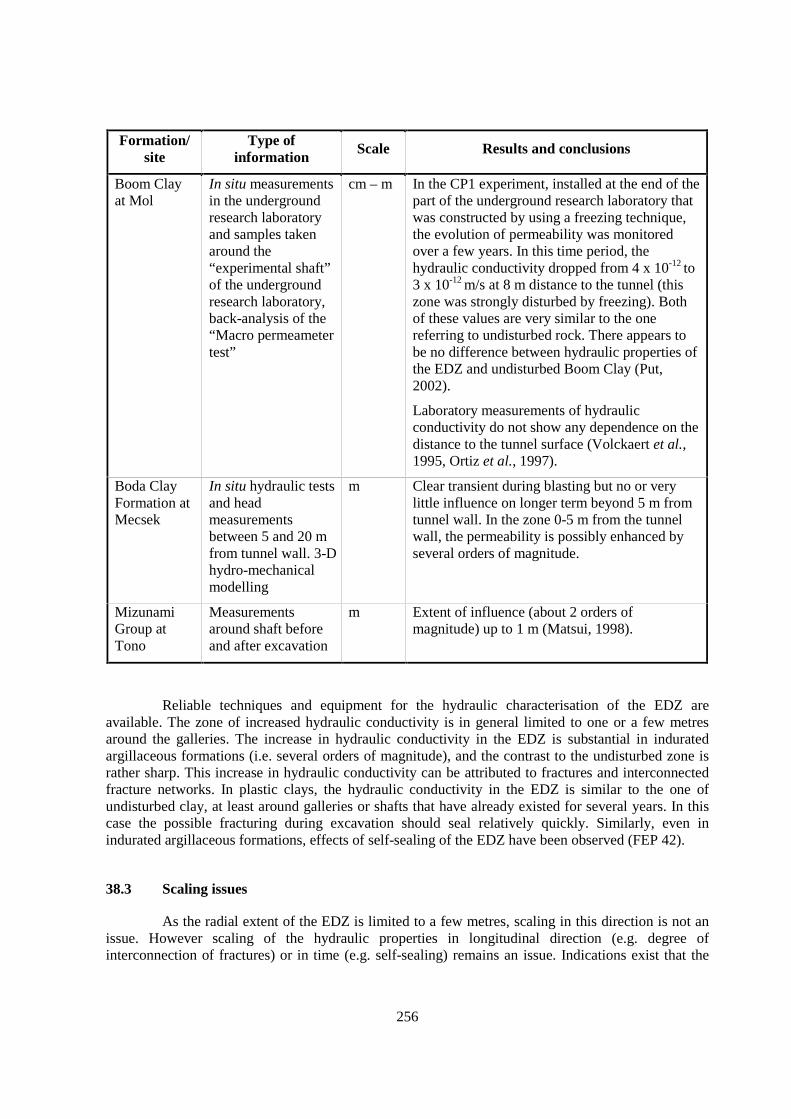
256
Formation/site
Type ofinformation
Scale Results and conclusions
Boom Clayat Mol
In situ measurementsin the undergroundresearch laboratoryand samples takenaround the“experimental shaft”of the undergroundresearch laboratory,back-analysis of the“Macro permeametertest”
cm – m In the CP1 experiment, installed at the end of thepart of the underground research laboratory thatwas constructed by using a freezing technique,the evolution of permeability was monitoredover a few years. In this time period, thehydraulic conductivity dropped from 4 x 10-12 to3 x 10-12 m/s at 8 m distance to the tunnel (thiszone was strongly disturbed by freezing). Bothof these values are very similar to the onereferring to undisturbed rock. There appears tobe no difference between hydraulic properties ofthe EDZ and undisturbed Boom Clay (Put,2002).
Laboratory measurements of hydraulicconductivity do not show any dependence on thedistance to the tunnel surface (Volckaert et al.,1995, Ortiz et al., 1997).
Boda ClayFormation atMecsek
In situ hydraulic testsand headmeasurementsbetween 5 and 20 mfrom tunnel wall. 3-Dhydro-mechanicalmodelling
m Clear transient during blasting but no or verylittle influence on longer term beyond 5 m fromtunnel wall. In the zone 0-5 m from the tunnelwall, the permeability is possibly enhanced byseveral orders of magnitude.
MizunamiGroup atTono
Measurementsaround shaft beforeand after excavation
m Extent of influence (about 2 orders ofmagnitude) up to 1 m (Matsui, 1998).
Reliable techniques and equipment for the hydraulic characterisation of the EDZ areavailable. The zone of increased hydraulic conductivity is in general limited to one or a few metresaround the galleries. The increase in hydraulic conductivity in the EDZ is substantial in induratedargillaceous formations (i.e. several orders of magnitude), and the contrast to the undisturbed zone israther sharp. This increase in hydraulic conductivity can be attributed to fractures and interconnectedfracture networks. In plastic clays, the hydraulic conductivity in the EDZ is similar to the one ofundisturbed clay, at least around galleries or shafts that have already existed for several years. In thiscase the possible fracturing during excavation should seal relatively quickly. Similarly, even inindurated argillaceous formations, effects of self-sealing of the EDZ have been observed (FEP 42).
38.3 Scaling issues
As the radial extent of the EDZ is limited to a few metres, scaling in this direction is not anissue. However scaling of the hydraulic properties in longitudinal direction (e.g. degree ofinterconnection of fractures) or in time (e.g. self-sealing) remains an issue. Indications exist that the
257
connectivity in the tangential direction is limited, leading to smaller hydraulic conductivities thanmeasured on a small scale.
38.4 Scientific level of understanding
Although many observations and measurements are available, the scientific understanding ofthe development of the EDZ and the evolution of its hydraulic parameters with time is rather low.
38.5 Linked FEPs
FEP 3 Migration pathways, including heterogeneity and anatomy
FEP 6 Hydraulic properties of the host rock
FEP 33 Thermally induced consolidation of the host rock
FEP 34 Geomechanical stability
FEP 35 Size and structure of the EDZ
FEP 36 Effects of bentonite swelling on the host rock
FEP 37 Geomechanical rock properties
FEP 39 State of saturation of the EDZ and desiccation cracking
FEP 40 Coupled thermo-hydro-mechanic processes
FEP 41 Swelling
FEP 42 Self-sealing
FEP 55 Present-day stress regime
38.6 Level of understanding from a PA perspective and treatment in PA
For clays with high plasticity, there are strong indications that “self-sealing” will lead to arather fast evolution of the hydraulic properties of the EDZ towards those of the undisturbed rock. Inthis case, from a PA point of view, there would be no difference in the hydraulic properties of the EDZand the undisturbed rock.
For highly indurated argillaceous rocks, the understanding of the hydraulic properties of theEDZ, their evolution and the extent of the EDZ are more critical than in the case of plastic clays. Ingeneral, the understanding of the development of the EDZ during construction and its later evolution israther limited. There are indications of self-sealing, but the process is slower and poorly understood.Due to these limitations, only a conservative treatment in PA is currently possible.
Mostly, this FEP is treated conservatively in PA, either by considering an effective thicknessof the natural argillaceous barrier that is the real thickness minus the supposed thickness of the EDZ,or by considering a high permeability zone around the excavations. Often this is considered incombination with a “seal failure” or “poor sealing” scenario.

258
38.7 Available reviews
NEA(2002b).
38.8 Planned work
At Mont Terri, the EH project is continued to study the slow self-sealing process in theframework of the SELFRAC project. After resaturation of the EDZ, fracture transmissivity decreasedsubstantially. Subsequently, bentonite swelling was simulated by load plates exerting pressure on thetunnel walls. Another substantial decrease of transmissivity of EDZ fractures was observed. Theexperiment is currently ongoing.
Both the EC CLIPEX and the SELFRAC projects study the effect of excavations on thedevelopment of the EDZ, its hydraulic properties and the potential for a subsequent self-sealing. In theunderground research laboratory at Mol, the planned measurements (among others using the CLIPEXinstrumentation) in relation to the excavation of the connection gallery should result in importantinformation of the time evolution of the EDZ and the governing hydro-mechanical processes.
38.9 Overall evaluation
This FEP is of high importance because the evolution of the hydraulic properties of the EDZdetermine to a large extent whether the EDZ can be a preferential pathway for radionuclide migrationor whether it will behave similar to the undisturbed host rock. Currently there are many observationson the extent and evolution of the hydraulic properties of the EDZ, however the understanding of thehydro-mechanical processes governing the EDZ and its evolution is still rather poor.
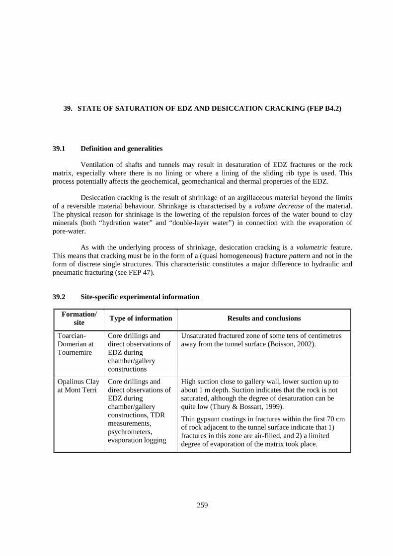
259
39. STATE OF SATURATION OF EDZ AND DESICCATION CRACKING (FEP B4.2)
39.1 Definition and generalities
Ventilation of shafts and tunnels may result in desaturation of EDZ fractures or the rockmatrix, especially where there is no lining or where a lining of the sliding rib type is used. Thisprocess potentially affects the geochemical, geomechanical and thermal properties of the EDZ.
Desiccation cracking is the result of shrinkage of an argillaceous material beyond the limitsof a reversible material behaviour. Shrinkage is characterised by a volume decrease of the material.The physical reason for shrinkage is the lowering of the repulsion forces of the water bound to clayminerals (both “hydration water” and “double-layer water”) in connection with the evaporation ofpore-water.
As with the underlying process of shrinkage, desiccation cracking is a volumetric feature.This means that cracking must be in the form of a (quasi homogeneous) fracture pattern and not in theform of discrete single structures. This characteristic constitutes a major difference to hydraulic andpneumatic fracturing (see FEP 47).
39.2 Site-specific experimental information
Formation/site Type of information Results and conclusions
Toarcian-Domerian atTournemire
Core drillings anddirect observations ofEDZ duringchamber/galleryconstructions
Unsaturated fractured zone of some tens of centimetresaway from the tunnel surface (Boisson, 2002).
Opalinus Clayat Mont Terri
Core drillings anddirect observations ofEDZ duringchamber/galleryconstructions, TDRmeasurements,psychrometers,evaporation logging
High suction close to gallery wall, lower suction up toabout 1 m depth. Suction indicates that the rock is notsaturated, although the degree of desaturation can bequite low (Thury & Bossart, 1999).
Thin gypsum coatings in fractures within the first 70 cmof rock adjacent to the tunnel surface indicate that 1)fractures in this zone are air-filled, and 2) a limiteddegree of evaporation of the matrix took place.
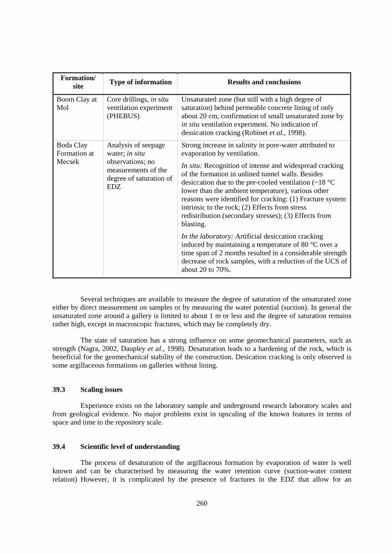
260
Formation/site Type of information Results and conclusions
Boom Clay atMol
Core drillings, in situventilation experiment(PHEBUS)
Unsaturated zone (but still with a high degree ofsaturation) behind permeable concrete lining of onlyabout 20 cm, confirmation of small unsaturated zone byin situ ventilation experiment. No indication ofdessication cracking (Robinet et al., 1998).
Boda ClayFormation atMecsek
Analysis of seepagewater; in situobservations; nomeasurements of thedegree of saturation ofEDZ
Strong increase in salinity in pore-water attributed toevaporation by ventilation.
In situ: Recognition of intense and widespread crackingof the formation in unlined tunnel walls. Besidesdesiccation due to the pre-cooled ventilation (~18 °Clower than the ambient temperature), various otherreasons were identified for cracking: (1) Fracture systemintrinsic to the rock; (2) Effects from stressredistribution (secondary stresses); (3) Effects fromblasting.
In the laboratory: Artificial desiccation crackinginduced by maintaining a temperature of 80 °C over atime span of 2 months resulted in a considerable strengthdecrease of rock samples, with a reduction of the UCS ofabout 20 to 70%.
Several techniques are available to measure the degree of saturation of the unsaturated zoneeither by direct measurement on samples or by measuring the water potential (suction). In general theunsaturated zone around a gallery is limited to about 1 m or less and the degree of saturation remainsrather high, except in macroscopic fractures, which may be completely dry.
The state of saturation has a strong influence on some geomechanical parameters, such asstrength (Nagra, 2002, Daupley et al., 1998). Desaturation leads to a hardening of the rock, which isbeneficial for the geomechanical stability of the construction. Desication cracking is only observed issome argillaceous formations on galleries without lining.
39.3 Scaling issues
Experience exists on the laboratory sample and underground research laboratory scales andfrom geological evidence. No major problems exist in upscaling of the known features in terms ofspace and time to the repository scale.
39.4 Scientific level of understanding
The process of desaturation of the argillaceous formation by evaporation of water is wellknown and can be characterised by measuring the water retention curve (suction-water contentrelation) However, it is complicated by the presence of fractures in the EDZ that allow for an
261
increased water exchange with the air in the gallery. The desaturation of the host rock, even when it isvery small, can have a strong influence on other processes as oxidation, especially of pyrite, of thehost rock and the increase of the salinity of the pore-water, both due to evaporation of water andoxidation. Thermal and geomechanical properties may also be affected, and these couplings arereasonably well studied.
It is generally felt that the mineralogical and physico-chemical reasons of desiccationcracking are sufficiently well understood. Deficiencies exist with regard to the in situ desiccationprocess caused by thermal loading.
39.5 Linked FEPs
FEP 32 Thermal rock properties
FEP 34 Geomechanical stability
FEP 35 Size and structure of the EDZ
FEP 37 Geomechanical rock properties
FEP 38 Hydraulic properties of the EDZ
39.6 Level of understanding from a PA perspective and treatment in PA
From a PA perspective, the state of saturation and its potential evolution with time issufficiently well understood, however the understanding of the associated coupled processes is still toolow to be accounted for in PA studies.
The importance of desiccation cracking for PA is considered to be rather minor, byconsequence not much attention is given to this issue. Only a limited number of rather simplesimulations were made to assess e.g. the time needed for resaturation. Within geomechanicalmodelling, desiccation cracking may be considered in an indirect manner, e.g. in the form of a genericincrease of the strength or permeability parameters. It is not considered to be a component of therepository system that would require explicit formulation.
39.7 Available reviews
None reported.
39.8 Planned work
Both at Mol and Mont Terri, further experiments are foreseen either in the framework ofEDZ studies or investigations of the influence of ventilation on the disturbed zone. The VE experimentat Mont Terri investigates the state of saturation of the EDZ 1) at the time of the excavation of a newtunnel and 2) 1 year later. Results are expected in 2003-2004.
262
39.9 Overall evaluation
As the extent of the unsaturated zone is small, the importance of this FEP is from a hydraulicpoint of view rather low. However, this FEP can have a strong influence on the pore-water chemistryin the EDZ, especially at sites where the EDZ fracture system would remain open and interconnectedfor a long time.
Desiccation cracking is a geomechanical phenomenon which is sufficiently well understood.It might occur locally within the backfill material and/or in the EDZ. In geomechanical modelling,desiccation cracks are not specifically modelled but may be considered in an indirect manner, e.g. byan adjustment of the strength or permeability parameters.

263
40. COUPLED THERMO-HYDRO-MECHANIC PROCESSES (FEP B5.1)
40.1 Definition and generalities
The generation of heat that will dissipate into the backfill and the surrounding host rock is awell-known characteristic of high-level radioactive waste emplaced in the underground. Theassociated mechanical, hydraulic, thermal and chemical effects are of potential importance for thebehaviour of the repository system, particularly in the affected field. In the far field, the effects arelimited as long as possible pore-water pressure and effective stress variations remain within acceptablelimits.
High-level radioactive waste constitutes a decaying heat source. For the surrounding hostrock, this implies that, after the heating stage, which is initiated at the time of waste emplacement,there will also be a cooling phase with a convergence towards the re-establishment of the naturalthermal conditions. The time span over which such a heat pulse is acting depends on the type of waste(less important for vitrified high-level waste and more important for spent fuel). Commonly it is of theorder of some 1 000 to some 10 000 y. The thermal impact is negligible for all other types of waste.
The heat pulse causes complex mechanical, hydraulic and chemical interactions in the hostrock, and all phases (gas, liquid, solid) need to be considered. Coupled thermal-hydraulic-mechanical(THM) models are generally required to adequately describe the repository response to the heat pulse.Of particular importance are thermally triggered changes in the transport of the fluids (hydraulicconductivity, gradient) and a possible non-linear behaviour of the solids, e.g. in form of permanentdeformations due to consolidation or due to cracking and fracturing (“heat cracks”; deterioration of therock material under the influence of heat). The influence of heat on hydraulic conductivity is wellknown and is due to the decrease of viscosity of water with increasing temperature.
40.2 Site-specific experimental information
Formation/site Results and conclusions
Opalinus Clay in theZürcher Weinland
Numerical modelling studies (Johnson et al., 2001, Nagra, 2002).
Boom Clay at Mol Coupled THM experiments (ATLAS, CACTUS, CERBERUS),numerical modeling of ATLAS in INTERCLAY 2.
In the PA for Opalinus Clay in the Zürcher Weinland, the main results are as follows: Themaximum temperature that can be expected to occur at the contact between the bentonite backfill andthe Opalinus Clay (EDZ) is 95°C. According to the very conservative model computations,temperatures in excess of 80°C are reached about 10 years after the emplacement of the waste. Themaximum temperature of 95°C is reached some 100 years after emplacement and is reduced to about
264
80°C after about 1 000 years. The Opalinus Clay is thus subjected to a temperature that is slightlyhigher than the maximum temperature of its geological past (ca. 85°C). The excess temperature of10°C is effective in the direct vicinity of the emplacement tunnels and is prevailing over a(geologically) rather short time span. In the first 1 000 years after the emplacement, both the bentonitebackfill and the rock in the EDZ are only partially saturated. The resulting high suction pressures andthe existence of a hydraulic gradient will cause a water transport from the surrounding host rocktowards the emplacement tunnels. The quantitative analysis of coupled effects associated to thethermal pulse yielded the following main results (Nagra, 2002, ch. 7.6.3):
• The most relevant effect is the increase of pore pressure (by max. 7 MPa at the interfaceof bentonite backfill and host rock, if the drainage that developed during constructionand operation is conservatively neglected). However, no fracturing is expected inconnection to this effect.
• Chemical, hydraulic and mechanical effects (see also FEPs 31 and 33) are of minorimportance.
For plastic clays with high water content, a qualitatively similar behaviour has been observedin the framework of the ATLAS, CACTUS and CERBERUS in situ THM experiments in Boom Clayat Mol. During heating, the thermal expansion of water induces a fast increase of pore-water pressureand total stress. Following the thermal pulse, pore-water pressure dissipates more quickly than totalstress, resulting in a consolidation of the clay. These experiments show a qualitative similaritybetween the behaviour of clay submitted to a thermal load and to a total stress increase.
40.3 Scaling issues
With regard to the understanding of the thermal pulse in space and time, no up- ordownscaling is required. Upscaling might, however, be required for the mechanical and hydraulicproperties (see FEPs 37 and 38).
40.4 Scientific level of understanding
The scientific level of understanding of this FEP is quite advanced. The following tablesummarises the possible hydro-mechanical effects of a heat pulse.
Process Possible consequences
Thermal expansion of the material(bentonite and rock) and of thepore-water
Pore pressure increase
Change of effective stress
Strength reduction of the material
Lowering of threshold value for the onset of creep
Increase of creep rate
Thermally-induced consolidation(treated in FEP 33)
Additional flow of water
Decrease of porosity and permeability
265
Thermal expansion: A temperature change influences the strength of a saturated materialsuch as bentonite or rock by means of changes of the pore-water pressure and thus of the state ofeffective stress. According to Campanella & Mitchell (1968) and Horseman (1994), the change of thepore-water pressure in an argillaceous material due to a temperature increase can be specified asfollows:
∆p = F ∗ ∆T ∗ σ’ with: ∆p = change of pore-water pressure∆T = temperature changeσ’ = effective stress F = Mitchell factor.
The Mitchell factor F is specified as follows:
F = e0 ((αs -αw)+αst/n)/0.434 Cs , wheree0 = initial void ration = porosityαs = coefficient of thermal expansion of the intact rockαw = coefficient of thermal expansion of waterαst = physico-chemical coefficient of expansionCs = swelling coefficient.
This equation shows that the Mitchell factor F is essentially controlled by three parameters:
1. The thermal expansion coefficient of water. The coefficient of thermal expansion of the rockmatrix is of less significance as it is typically one order of magnitude smaller than that ofwater.
2. The physico-chemical coefficient of expansion of the texture of the argillaceous material αst.This coefficient is different from that of the thermal expansion of the clay-mineral plateletsas it is significantly affected by the changes of the adhesive forces of water and of theosmotic forces. According to Campanella & Mitchell (1968) the parameter αst is about- 0.5∗10-4 °C-1.
3. The swelling coefficient Cs, which describes the compressibility of the rock matrix. Cs canbest be deduced from the so-called storage coefficient (Horseman 2002). From hydraulictests the storage coefficient of the Opalinus Clay was determined at 1.5 x 10⁻⁵ m-1.
The level of scientific understanding of further thermally-induced expansion effects (seeTable above) is discussed in Nagra (2002, ch. 7.6). The effects include the strength reduction of thematerial, the lowering of threshold value for the onset of creep and the increase of creep rate.Calculations show that all these effects are not relevant at least in the case of Opalinus Clay.
Thermal consolidation and secondary compaction: According to Campanella & Mitchell(1968), subjecting an argillaceous material to a temperature increase leads to a consolidation processwhich is similar to conventional mechanical consolidation (thermal stress instead of mechanical stress;see FEP 33).
266
40.5 Linked FEPs
FEP 32 Thermal rock properties
FEP 33 Thermally induced consolidation of the host rock
FEP 35 Size and structure of the EDZ
FEP 37 Geomechanical rock properties
FEP 38 Hydraulic properties of the EDZ
FEP 39 State of saturation of the EDZ and desiccation cracking
40.6 Level of understanding from a PA perspective and treatment in PA
The level of understanding appears sufficient for a PA. The most significant disturbancecaused by a heat pulse is the transient increase of the pore-water pressure in most parts of thegeological repository. The excess pore-water pressure, however, is released (1) by squeezing out ofpore-water and (2) by subsequent lowering of the temperature due to the decay of the heat pulse.
For a PA this FEP has to be covered by extensive numerical modelling studies. The studieshave to be based on highly specialised T-H-M coupled numerical codes. Appropriate codes arecommercially available from various sources. However, there still seems to be a lack of reliable site-specific parameter sets and of reference sites for the validation of coupled T-H-M numerical models.
40.7 Available reviews
None reported.
40.8 Planned work
Formation/site Planned activitiesOpalinus Clay at MontTerri
The HE-heater experiment, including modelling of thermally inducedH-M effects.
Boom Clay at Mol Large heater experiment and associated numerical modelling.
40.9 Overall evaluation
The level of generic understanding of this FEP is quite advanced. The thermal expansion of asaturated rock is predominantly controlled by the coefficient of thermal expansion of the water. Therespective coefficient of the rock matrix is of less significance as it is typically by about one order ofmagnitude smaller than that of water. A temperature change influences the strength of a saturatedmaterial predominantly by means of changes of the pore-water pressure and thus of the state ofeffective stress.
The most significant disturbance caused by a HLW heat pulse is the transient increase of thepore-water pressure in most parts of the geological repository. The excess pore-water pressure,however, is released (1) by squeezing out of pore-water and (2) by subsequent lowering of thetemperature due to the decay of the heat pulse.
267
41. SWELLING (FEP B5.2, C2.3)
41.1 Definition and generalities
Swelling is a volume increase of a material (argillaceous host rock in the EDZ or backfill inthe emplacement gallery) due to adsorption of water on clay minerals. Nüesch (1991) distinguishes“inner-crystalline swelling” due to the insertion of hydration water and “osmotic swelling” due to theadsorption of diffuse double-layer water. In confined conditions, as is typical for both a tightlybackfilled emplacement gallery and the EDZ, swelling pressures of considerable magnitude candevelop.
Swelling is one of the processes that contribute to self-sealing of the EDZ as well as ofnatural fractures (see FEP 42). The capacity of an argillaceous rock to swell when exposed to freewater depends on: (a) clay mineralogy, (b) degree of cementation of the matrix, (c) stress history, and(d) water chemistry. Water is drawn into the clay fabric by physico-chemical forces, and this inwardmovement of water molecules into the interparticle spaces causes the fabric to expand. In unconfinedconditions the resulting volumetric strain is always substantially larger than what can be explained byinvoking simple poroelastic concepts. The presence of an interparticle cement can inhibit swelling ofthe clay fabric. However, cementing agents such as calcite and silica tend to behave in a brittle mannerand are easily damaged in the formation process of the EDZ. In fact, it appears likely that fabricdamage is a necessary pre-requisite for swelling in some argillaceous rocks. Many argillaceous rocksalso exhibit a progressive process of fabric breakdown referred to as softening. This is a gradualalteration of a hard rock into a plastic soil-like clay material with substantially reduced shear strength(Bott 1986). The water content of a softened argillaceous rock is significantly larger than that of theparent material showing that swelling and softening are closely interlinked. Softening commencesaround fissures and fractures. It seems likely that the combined processes of swelling and softeningwill lead to a gradual decrease of fracture permeability.
268
41.2 Site-specific experimental information
Formation/site Investigation techniquesemployed Results and conclusions
Toarcian-Domerian atTournemire
Laboratory swelling andshrinkage tests on samplesfrom boreholes (equiv.oedometer cells with in situwater)
Swelling pressure normal and parallel tobedding:ps ⊥ ss = 0.1 to 0.6 MPaps // ss = 0.3 to 0.5 MPa.
Swelling strain anisotropy (normal/parallel):0.4-1.3.
Swelling strain normal to bedding: 1.3-1.5%.
Rather low swelling pressure under naturalconfining pressure. Shrinkage-swelling cyclesshow a hysteresis, probably linked to changes inthe texture of the material (Daupley, 1997,Boisson et al., 1998).
Callovo-Oxfordian at Bure
Laboratory swelling andshrinkage/swelling tests(oedometer and triaxial)
Numerical modelling on theeffects of ventilation on thehost rock
Swelling pressure of about 0.8 to 1 MPa(in oedometer tests). Swelling occurs even under12 MPa confining pressure (in triaxial tests;Andra, 1998). Part of shrinkage is irreversible(in cyclic shrinkage-swelling tests; Andra,1999b).
Opalinus Clay atMont Terri (Bock2000)
Laboratory experiments Swelling pressure normal and parallel tobedding:ps ⊥ ss = 1.2 MPaps // ss = 0.6 MPa.
Boom Clay atMol (Ortiz et al.1997)
Laboratory analysis:presence of swelling clayminerals
Swelling pressure ≈ 1 MPa, measurement ofpermeability as a function of swelling showsmaximum increase by less then a factor 2.
41.3 Scaling issues
Beyond the laboratory scale as described above, this FEP can, in principle, be characterisedat full scale in underground research laboratories. Experiments will be limited to practical time periods(a few years maximum) and it is necessary to make extrapolations of the behaviour over much longerPA time scales.
41.4 Scientific level of understanding
Generally, the level of understanding of swelling and of the underlying physico-chemicalprocesses is reasonably good.

269
41.5 Linked FEPs
FEP 14 Lithology, mineralogy of rocks and fracture infills
FEP 17 Pore- and fracture water composition
FEP 30 Organics from waste and their effect on transport properties of the host rock
FEP 37 Geomechanical rock properties
FEP 38 Hydraulic properties of the EDZ
FEP 39 State of saturation of the EDZ and desiccation cracking
FEP 52 Future changes in hydrochemistry of the host rock and of surrounding formations (e.g. due toout-diffusion, water-rock interactions, uplift)
41.6 Level of understanding from a PA perspective and treatment in PA
The level of generic understanding of swelling is generally quite good. It needs to beconsidered in several aspects of site characterisation, repository design and PA:
• Numerous case studies in civil and mining underground construction have demonstratedthe particular importance of swelling for the design and excavation of the repositorytunnels and galleries and of the ground support system.
• Swelling is one of the major causes of borehole instability in argillaceous formations.Purpose-designed drilling fluids or dry drilling can minimise the effects. It also has(often undesired) effects on in situ tests and experiments (e.g. hydraulic andgeomechanical characterisation).
• Laboratory experiments (e.g. percolation and diffusion tests) may be affected byswelling. In many cases, swelling and related self-sealing are welcome effects becausethey reduce the likelihood of artificial short-circuits. On the other hand, the volumechange related to water saturation under unconfined laboratory conditions may be anundesired effect. At least for Opalinus Clay, it was shown that saturation underunconfined conditions results in water contents well above those that refer to in situconditions, with consequences for the parameters that are characterised by theexperiment (e.g. shear strength).
• Swelling is one of the mechanisms underlying self-sealing and thus plays a role for thedevelopment of the hydraulic characteristics of the EDZ as well as of natural fractures.
In spite of a generally good generic understanding, site-specific characterisation andparametrisation at appropriate scales is less well developed. Insufficient experimental results areavailable from on-site tests and observations. In general, there is a definite need for site-specificinformation on the permeability of the EDZ over the time period of PA. This will necessitateextrapolation of experimental data from work undertaken in underground research laboratories. Suchinformation would also be useful for the understanding of self-sealing in natural fractures.
270
41.7 Available reviews
None reported.
41.8 Planned work
None reported.
41.9 Overall evaluation
This FEP is important for site characterisation, construction and PA. It needs to be explicitlyconsidered in the design of the underground structures of the repository. It has major repercussions onthe time-dependent development of the permeability characteristics of the EDZ and is one of the keysin triggering self-sealing of repository-induced fractures. The capacity of swelling and, implicitly, ofself-sealing needs to be examined on a rock- and site-specific basis.

271
42. SELF-SEALING (FEP B5.3, C2.4)
42.1 Definition and generalities
Self-sealing is a process that leads to a reduction to the hydraulic transmissivity of a fracture.On the other hand, self-healing includes the reduction in the impact of a fracture on both the hydraulicand mechanical properties of the rock mass (Horseman, 2001).
The capacity of fractures in argillaceous rocks to self-seal (or become, with the passage oftime, less conductive to ground water) is often cited as a primary factor favouring the choice of suchmaterials as host rocks for deep disposal. Self-sealing mechanisms have been widely observed in avariety of argillaceous rocks. The underlying processes which contribute to self-sealing can be broadlysubdivided into two categories: (a) hydro-mechanical processes linked to the change in the stress field,the movement of water and time-dependent rock deformation, and (b) geochemical processes linked tochanges in both the composition and the fabric of the rock.
Horseman (2001) emphasised the role of hydro-mechanical processes in self-sealing andsuggested that the main consideration in assessing the capacity for self-sealing is the temporalevolution of the stress path. Qualitative arguments were based on the Modified Cam-Clay Modelwhich describes the deformation and failure of porous rocks. The state boundary surface is assumed tocomprise the Hvorslev Surface for material on the “dry side” of the critical state line and the RoscoeSurface for material on the "wet side" (Shah, 1997). Shear deformation on the “dry side” favoursdilatant shear fracturing, whereas shear deformation on the “wet side” favours contractant behaviour.According to this model, the EDZ is formed when the stress path touches the Hvorslev surface. Thecombined effect of stress relief and shear-induced dilatancy is a significant reduction in the pore-waterpressure. It seems probable that pore-water pressures can actually become negative in sign (i.e. a stateof suction) close to the walls of the repository excavation, leading to localised de-saturation. Thedilatant response will also lead to a measurable increase in the permeability of the EDZ.
Within this FEP, the self-sealing of migration pathways is considered, irrespectively ofwhether these pathways are natural or man-induced in origin. Self-sealing may occur in naturalfractures subsequent to movements along these (e.g. due to earthquakes, fault (re)activation, uplift andsubsidence) or in EDZ fractures (e.g. due to resaturation, swelling pressures of bentonite-basedbackfills, creep). Self-sealing in argillaceous rocks can be triggered essentially by three mechanisms:
1. Closing of fractures (pathways) by swelling, i.e. a volume increase of some clay minerals(mainly of the smectite group) by water uptake (see FEP 41);
2. Filling of fissures and fractures through the generation of infilling materials or mineralprecipitation;
3. Closing of fractures (pathways) resulting from mechanical deformation, i.e. plasticdeformation of the argillaceous layer under the acting geomechanical stress field.
In many cases these mechanisms will occur simultaneously and will complement each other.
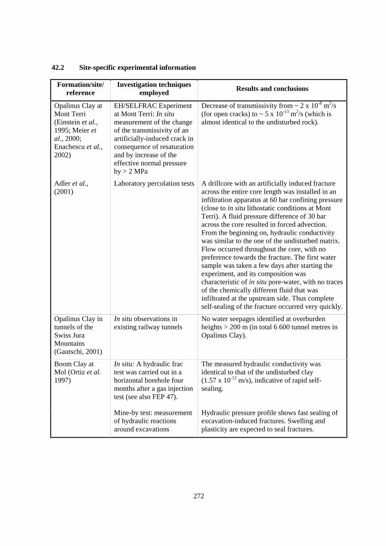
272
42.2 Site-specific experimental information
Formation/site/reference
Investigation techniquesemployed Results and conclusions
Opalinus Clay atMont Terri(Einstein et al.,1995; Meier etal., 2000;Enachescu et al.,2002)
EH/SELFRAC Experimentat Mont Terri: In situmeasurement of the changeof the transmissivity of anartificially-induced crack inconsequence of resaturationand by increase of theeffective normal pressureby > 2 MPa
Decrease of transmissivity from ~ 2 x 10⁻⁸ m2/s(for open cracks) to ~ 5 x 10-13 m2/s (which isalmost identical to the undisturbed rock).
Adler et al.,(2001)
Laboratory percolation tests A drillcore with an artificially induced fractureacross the entire core length was installed in aninfiltration apparatus at 60 bar confining pressure(close to in situ lithostatic conditions at MontTerri). A fluid pressure difference of 30 baracross the core resulted in forced advection.From the beginning on, hydraulic conductivitywas similar to the one of the undisturbed matrix.Flow occurred throughout the core, with nopreference towards the fracture. The first watersample was taken a few days after starting theexperiment, and its composition wascharacteristic of in situ pore-water, with no tracesof the chemically different fluid that wasinfiltrated at the upstream side. Thus completeself-sealing of the fracture occurred very quickly.
Opalinus Clay intunnels of theSwiss JuraMountains(Gautschi, 2001)
In situ observations inexisting railway tunnels
No water seepages identified at overburdenheights > 200 m (in total 6 600 tunnel metres inOpalinus Clay).
Boom Clay atMol (Ortiz et al.1997)
In situ: A hydraulic fractest was carried out in ahorizontal borehole fourmonths after a gas injectiontest (see also FEP 47).
The measured hydraulic conductivity wasidentical to that of the undisturbed clay(1.57 x 10⁻¹² m/s), indicative of rapid self-sealing.
Mine-by test: measurementof hydraulic reactionsaround excavations
Hydraulic pressure profile shows fast sealing ofexcavation-induced fractures. Swelling andplasticity are expected to seal fractures.
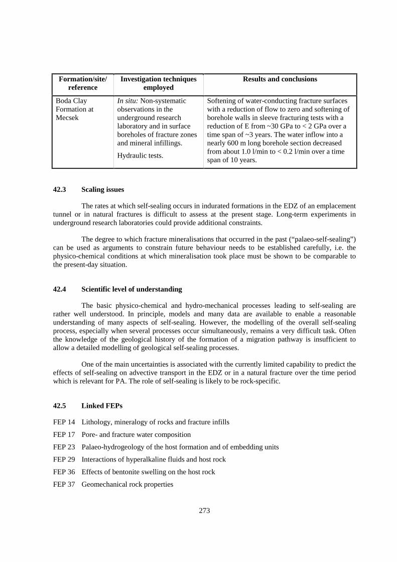
273
Formation/site/reference
Investigation techniquesemployed
Results and conclusions
Boda ClayFormation atMecsek
In situ: Non-systematicobservations in theunderground researchlaboratory and in surfaceboreholes of fracture zonesand mineral infillings.
Hydraulic tests.
Softening of water-conducting fracture surfaceswith a reduction of flow to zero and softening ofborehole walls in sleeve fracturing tests with areduction of E from ~30 GPa to < 2 GPa over atime span of ~3 years. The water inflow into anearly 600 m long borehole section decreasedfrom about 1.0 l/min to < 0.2 l/min over a timespan of 10 years.
42.3 Scaling issues
The rates at which self-sealing occurs in indurated formations in the EDZ of an emplacementtunnel or in natural fractures is difficult to assess at the present stage. Long-term experiments inunderground research laboratories could provide additional constraints.
The degree to which fracture mineralisations that occurred in the past (“palaeo-self-sealing”)can be used as arguments to constrain future behaviour needs to be established carefully, i.e. thephysico-chemical conditions at which mineralisation took place must be shown to be comparable tothe present-day situation.
42.4 Scientific level of understanding
The basic physico-chemical and hydro-mechanical processes leading to self-sealing arerather well understood. In principle, models and many data are available to enable a reasonableunderstanding of many aspects of self-sealing. However, the modelling of the overall self-sealingprocess, especially when several processes occur simultaneously, remains a very difficult task. Oftenthe knowledge of the geological history of the formation of a migration pathway is insufficient toallow a detailed modelling of geological self-sealing processes.
One of the main uncertainties is associated with the currently limited capability to predict theeffects of self-sealing on advective transport in the EDZ or in a natural fracture over the time periodwhich is relevant for PA. The role of self-sealing is likely to be rock-specific.
42.5 Linked FEPs
FEP 14 Lithology, mineralogy of rocks and fracture infills
FEP 17 Pore- and fracture water composition
FEP 23 Palaeo-hydrogeology of the host formation and of embedding units
FEP 29 Interactions of hyperalkaline fluids and host rock
FEP 36 Effects of bentonite swelling on the host rock
FEP 37 Geomechanical rock properties

274
FEP 38 Hydraulic properties of the EDZ
FEP 39 State of saturation of the EDZ and desiccation cracking
FEP 41 Swelling
FEP 50 Past burial history
FEP 52 Future changes in hydrochemistry of the host rock and of surrounding formations (e.g. due toout-diffusion, water-rock interactions, uplift)
FEP 56 Future stress regime
42.6 Level of understanding from a PA perspective and treatment in PA
This FEP is used in PA studies mostly at the scenario development stage. From a PAperspective, the current level of understanding of self-sealing mechanisms is sufficient to judgewhether in a given argillaceous formation newly formed fractures could remain open, i.e. remainimportant migration pathways for a long time or not. However, the detailed modelling of the closure ofsuch migration pathways, especially by infilling minerals, remains difficult. There are few examples(e.g. the Opalinus Clay PA) of the assessment of the possible effect of fractures on the overall safetyof a repository.
42.7 Available reviews
The current level of understanding is summarised in Horseman (2001). The NEA hascommissioned an overview report on the self-sealing of fractures under repository conditions.
42.8 Planned work
In the EC project SELFRAC, the self-sealing mechanisms in Boom Clay and Opalinus Clayare studied, at Mont Terri the EH self-sealing test is still ongoing. Although these projects are mainlyoriented on self-sealing of the EDZ, they will increase our understanding of self-sealing processes ingeneral.
Formation/site Planned activities
Generic/several sites A synthetic overview of the underlying processes and compilation ofempiric evidence for self-sealing is currently being elaborated at the BritishGeological Survey. This project was commissioned by the Clay Club, aworking group of the NEA.
Callovo-Oxfordian atBure
Self-sealing studies are in progress within the framework of the Andra-sponsored FORPRO French research network.
Opalinus Clay at MontTerri
In situ permeability tests of fracture planes under variation of the normalstress conditions. The changes are implemented from the tunnel excavationsurface by means of a large-scale plate bearing test. This test is part of theSELFRAC project.
Boom Clay at Mol Self-sealing studies are in progress within the framework of the EU projectSELFRAC.
275
42.9 Overall evaluation
For disposal in argillaceous formations, this FEP is very important as self-sealing ofmigration pathways is a process that can give a very large contribution to the confining properties ofargillaceous host rocks and to the robustness of disposal in argillaceous materials. Self-sealing isexpected to occur in a wide variety of argillaceous formations. Although the understanding of self-sealing processes is already well-developed, studies should be continued to allow more quantitativeassessments.

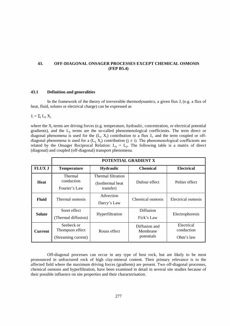
277
43. OFF-DIAGONAL ONSAGER PROCESSES EXCEPT CHEMICAL OSMOSIS(FEP B5.4)
43.1 Definition and generalities
In the framework of the theory of irreversible thermodynamics, a given flux Ji (e.g. a flux ofheat, fluid, solutes or electrical charge) can be expressed as
Ji = Σj Lij Xj
where the Xj terms are driving forces (e.g. temperature, hydraulic, concentration, or electrical potentialgradients), and the Lij terms are the so-called phenomenological coefficients. The term direct ordiagonal phenomena is used for the (Lii Xi) contribution to a flux Ji, and the term coupled or off-diagonal phenomena is used for a (Lij Xj) contribution (j ������������������������������������������related by the Onsager Reciprocal Relation: Lij = Lji. The following table is a matrix of direct(diagonal) and coupled (off-diagonal) transport phenomena.
POTENTIAL GRADIENT X
FLUX J Temperature Hydraulic Chemical Electrical
HeatThermal
conduction
Fourier’s Law
Thermal filtration
(Isothermal heattransfer)
Dufour effect Peltier effect
Fluid Thermal osmosisAdvection
Darcy’s LawChemical osmosis Electrical osmosis
SoluteSoret effect
(Thermal diffusion)Hyperfiltration
Diffusion
Fick’s LawElectrophoresis
CurrentSeebeck or
Thompson effect
(Streaming current)
Rouss effectDiffusion and
Membranepotentials
Electricalconduction
Ohm’s law
Off-diagonal processes can occur in any type of host rock, but are likely to be mostpronounced in unfractured rock of high clay-mineral content. Their primary relevance is to theaffected field where the maximum driving forces (gradients) are present. Two off-diagonal processes,chemical osmosis and hyperfiltration, have been examined in detail in several site studies because oftheir possible influence on site properties and their characterisation.

278
This FEP discusses scoping calculations on the relative importance to repositoryperformance of all coupled phenomena except those including electric potentials or currents, which arenot considered relevant. The focus is on processes in the affected field. Chemical osmosis is amechanism that may have some relevance for the characterisation of the far field, and these aspects arediscussed in FEP 44.
43.2 Site-specific experimental information
The importance of off-diagonal processes has been evaluated in field and laboratory studiesand theoretically, using site-specific, literature and bounding values for coupling coefficients. Studiesrelevant to waste management are summarised in the following table:
Formation/site Type of Study Coupling(s)Investigated References
Callovo-Oxfordian at Bure Field / scopingcalculation
Chemicalosmosis
Andra (1999a)
Opalinus Clay at Mont Terriunder representativerepository conditions
Theoretical All exceptelectrical
Soler (1999, 2001)
Opalinus Clay at Mont Terri Field andlaboratory
Chemicalosmosis
Harrington & Horseman (1999,2000); continuing work inprogress; see FEP 44
Boom Clay at Mol Laboratory Hyperfiltration in progress
Pierre Shale in south Dakota Field Chemicalosmosis
Neuzil (1994, 2000);See FEP 44
Kaolinite and WyomingBentonite under assumedrepository conditions
Theoretical All exceptelectrical
Carnahan (1984, 1985)summarised by Horseman et al.(1996, ch. 10.6)
Soler (1999, 2001) explored the possible importance of coupled processes to repositoryperformance in the affected field. He did this by calculating estimates of the fluid and solute fluxesassociated with the coupled processes thermal osmosis, chemical osmosis, thermal diffusion andhyperfiltration, and comparing them with fluxes due to the direct (diagonal) processes advection anddiffusion. The conditions were those of a fully saturated Opalinus Clay, at time scales equal to orgreater than the expected lifetime of the waste canisters (about 1 000 y). Estimates based on fluxesalone suggest that thermal osmosis is the only coupled transport mechanism that could have a strongimpact on solute and fluid transport in the vicinity of the repository. However, when conservation offluid mass is taken into account in two- and three-dimensional flow models including only advection(Darcy’s law) and thermal osmosis, the advective component of flow cancels the thermal-osmoticcomponent arising from the presence of a heat source in the interior of the flow domain. Chemicalosmosis would only have a minor effect according to the first estimates. Also, estimates regarding thepossible role of thermal filtration and the Dufour effect on heat transport suggest that the effect ofthese coupled heat transport mechanisms is negligible compared to heat transport by thermalconduction.

279
43.3 Scaling issues
None reported.
43.4 Scientific level of understanding
Chemical osmosis (FEP 44) and hyperfiltration are well-understood from the point of viewof the mechanisms behind the transport phenomena. They are due to the existence of diffuse ionicdouble layers in solution next to the clay-mineral surfaces. Thermal diffusion (Soret effect) has beenstudied for many years by many different investigators in different systems. It is well-established as asolute transport mechanism. There is little understanding of the mechanisms underlying thermalfiltration and the Dufour effect.
Only two laboratory studies on thermal osmosis in argillaceous material are cited by Soler(1999, 2001). These give values of thermo-osmotic permeabilities from 10-14 to 10-10 m2/K/s. Soler’scalculations show that thermo-osmotic fluxes far exceed advective and diffusive fluxes at thermo-osmotic permeability values much above 10-12 m2/K/s. Modelling coupled thermo-osmotic andadvective fluxes shows that they cancel leading to very low net fluxes, but to evaluate thermo-osmoticfluxes alone site-specific thermo-osmotic permeability values should be available.
43.5 Linked FEPs
FEP 6 Hydraulic properties of the host rock
FEP 8 Diffusivity
FEP 10 Ion exclusion
FEP 32 Thermal rock properties
FEP 38 Hydraulic properties of the EDZ
43.6 Level of understanding from a PA perspective and treatment in PA
Off-diagonal processes are not included in models used for PA calculations, but can beexamined in separate scoping calculations, as was done for the Opalinus Clay. Bounding values forcoupled flux parameters may be sufficient to demonstrate that certain processes are not important. Ifsuch calculations show that the processes could be important, it may be necessary to measure specificcoupling parameters.
Based on current understanding, thermal osmosis is the only off-diagonal Onsager processthat could potentially affect the affected-field performance of a repository in the Opalinus Clay.However, further calculations indicate that this too has only a small effect, at least at times beyondcanister failure (when the system is likely to be fully saturated). Thermal osmosis may play some rolein the resaturation process, but other phenomena are likely to be more important.
On the basis of numerical experiments, it is judged that off-diagonal Onsager processes canbe neglected in the formulation of geosphere transport models for Opalinus Clay. The possible role ofchemical osmosis in the far field is addressed in FEP 44.
280
43.7 Available reviews
Coupled processes are not widely studied so each site-specific reference given above in thetable in Section II, Chapter 43.2 includes a review of the subject. Those of Horseman et al. (1996) andSoler (1999, 2001) are particularly useful.
43.8 Planned work
As shown in the table in Section II, Chapter 43.2 and discussed in FEP 44, laboratory andfield work on chemical osmosis and hyperfiltration are under way in connection with siteinvestigations of the Opalinus Clay at Mont Terri, the Callovo-Oxfordian at Bure and the Boom Clayat Mol. No studies of other types of coupling are planned.
43.9 Overall evaluation
Based on the calculations of Soler (1999, 2001), the relevance of off-diagonal processes inthe affected field of a repository is low. Thus, further work should be assigned a low priority, althoughany developments reported in the literature should be followed.

281
44. CHEMICAL OSMOSIS (FEP B5.5)
44.1 Definition and generalities
Chemical osmosis is the most studied off-diagonal Onsager process. It refers to the fluidpressures or fluxes that develop across a semipermeable membrane in response to a chemicalconcentration gradient. The converse process, called hyperfiltration, is the process by which solutemolecules are prevented by their size and/or charge from passing through a membrane. Hyperfiltrationmay increase the concentration of solutes within or on the upstream side of a membrane through whicha solvent is flowing.
The solvent flux due to chemical osmosis, q, is commonly expressed by an equationanalogous to Darcy’s law (here written for flow in the x-direction):
qΠ = σ k/µ �Π/���
and the osmotic pressure, Π, given by
Π = - [RT/Vw] ln aw.
In the first expression, k = permeability, µ = dynamic viscosity, σ = osmotic efficiency, and�Π = loss of osmotic pressure across ���������������� ��!w and aw are the molar volume and activity ofwater, respectively, R is the gas constant and T is absolute temperature (Neuzil, 2000, Soler, 1999,2001).
Scoping calculations, based on properties of the Opalinus Clay and discussed in FEP 43,suggest that chemical osmosis in unlikely to affect the affected-field performance of a repository afterresaturation. However, there are four aspects of site characterisation (far field) to which osmosis maybe of potential importance:
• as a driving force for fluid flow;
• as a cause of hydraulic overpressures;
• as a cause of erroneous hydraulic pressure measurements due to concentration gradientsbetween borehole and formation fluids; and
• as a thermodynamic potential that affects the geomechanical rock properties (e.g.swelling, mechanical instability).
These potential effects of chemical osmosis are discussed in this FEP.
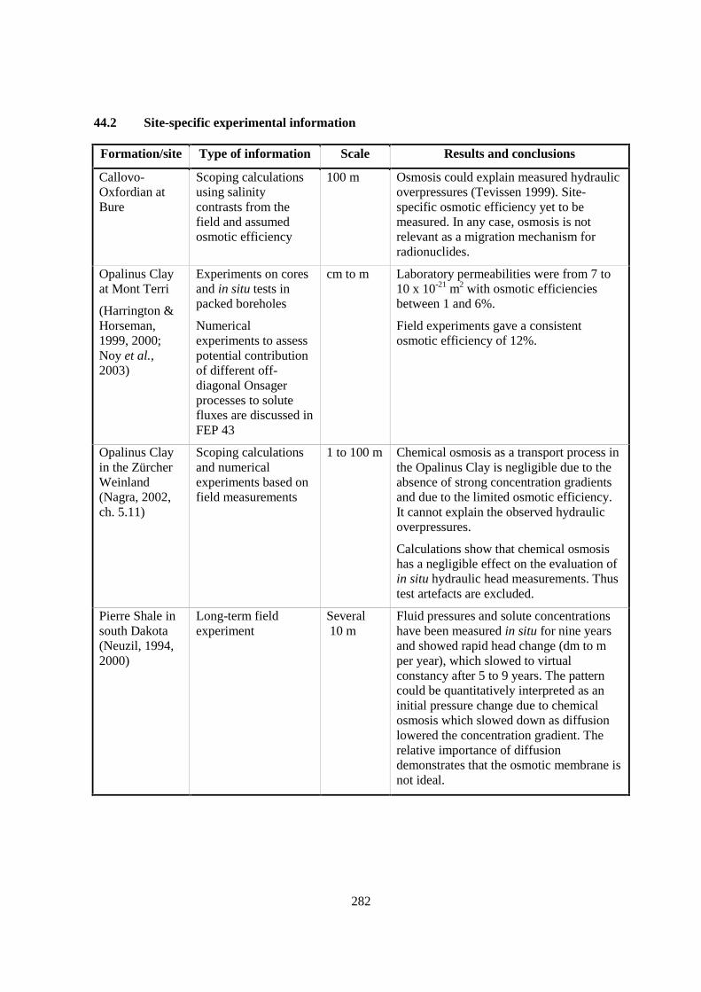
282
44.2 Site-specific experimental information
Formation/site Type of information Scale Results and conclusions
Callovo-Oxfordian atBure
Scoping calculationsusing salinitycontrasts from thefield and assumedosmotic efficiency
100 m Osmosis could explain measured hydraulicoverpressures (Tevissen 1999). Site-specific osmotic efficiency yet to bemeasured. In any case, osmosis is notrelevant as a migration mechanism forradionuclides.
Opalinus Clayat Mont Terri
(Harrington &Horseman,1999, 2000;Noy et al.,2003)
Experiments on coresand in situ tests inpacked boreholes
Numericalexperiments to assesspotential contributionof different off-diagonal Onsagerprocesses to solutefluxes are discussed inFEP 43
cm to m Laboratory permeabilities were from 7 to10 x 10-21 m2 with osmotic efficienciesbetween 1 and 6%.
Field experiments gave a consistentosmotic efficiency of 12%.
Opalinus Clayin the ZürcherWeinland(Nagra, 2002,ch. 5.11)
Scoping calculationsand numericalexperiments based onfield measurements
1 to 100 m Chemical osmosis as a transport process inthe Opalinus Clay is negligible due to theabsence of strong concentration gradientsand due to the limited osmotic efficiency.It cannot explain the observed hydraulicoverpressures.
Calculations show that chemical osmosishas a negligible effect on the evaluation ofin situ hydraulic head measurements. Thustest artefacts are excluded.
Pierre Shale insouth Dakota(Neuzil, 1994,2000)
Long-term fieldexperiment
Several 10 m
Fluid pressures and solute concentrationshave been measured in situ for nine yearsand showed rapid head change (dm to mper year), which slowed to virtualconstancy after 5 to 9 years. The patterncould be quantitatively interpreted as aninitial pressure change due to chemicalosmosis which slowed down as diffusionlowered the concentration gradient. Therelative importance of diffusiondemonstrates that the osmotic membrane isnot ideal.
283
44.3 Scaling issues
None reported.
44.4 Scientific level of understanding
Chemical osmosis is well-understood from the point of view of the mechanism behind thetransport phenomenon. However, quantitative modelling of the effect of osmosis within a naturalargillaceous formation (i.e. a complex mixture of different clay minerals) is rather poorly understood,among other reasons due to the scarcity of measurements of osmotic efficiency.
44.5 Linked FEPs
FEP 6 Hydraulic properties of the host rock
FEP 8 Diffusivity
FEP 10 Ion exclusion
FEP 17 Pore- and fracture water composition
FEP 38 Hydraulic properties of the EDZ
44.6 Level of understanding from a PA perspective and treatment in PA
The effects of chemical osmosis in the affected field are negligible. Similarly, it isconsidered to be irrelevant as a transport process for radionuclides in the far field. For these reasons,chemical osmosis is currently neglected in PA. Few data exist regarding osmotic efficiency ofargillaceous rocks but appear to indicate that such rocks are only non-ideal membranes.
On the other hand, chemical osmosis is a possible explanation of hydraulic overpressuresobserved in some argillaceous formations, and thus needs attention from a viewpoint of sitecharacterisation and system understanding. It may also be considered in the evaluation of hydraulichead measurements in boreholes, in particular if the test fluid has a salinity that is substantiallydifferent from that of the in situ pore-water.
44.7 Available reviews
Horseman et al. (1996).
44.8 Planned work
None reported.
44.9 Overall evaluation
This process can be neglected in comparison with other transport processes and need not beimplemented in models used for PA.

284
However, laboratory and field evidence show that chemical osmosis due to natural orintroduced concentration gradients can produce anomalous pressures. Such pressures could lead tomisunderstanding of the hydraulic heads driving regional flow, to incorrect interpretations of hydraulichead measurements in boreholes, and to mechanical instability in boreholes and undergroundworkings from osmotic pressures developed in the formation.
285
45. GAS DISSOLUTION AND CHEMICAL INTERACTIONSBETWEEN GAS AND PORE-WATER (FEP B6.1)
45.1 Definition and generalities
This FEP is concerned with gases dissolved in the pore and fracture water in situ and thedissolution of gases present during the operational phase of the repository and/or from degradation ofparts of the engineered barrier system. It further addresses the chemical interactions that might occurbetween pore-water and gases. In is relevant to the affected field in connection with the EDZ
The solubility of a gas depends on the partial pressure of the gas and its temperature-dependent Henry’s Law or other gas law constants. In a closed system (a system with a limited totalgas volume) the dissolved concentration also depends on the volume ratio of solution to total gas(Stumm & Morgan, 1996). Henry’s Law constants are commonly included in the thermodynamic databases used for geochemical modelling (see FEP 22). Other forms of gas solubility data (e.g. IUPAC orvan der Waals expressions) are summarised in handbooks (e.g. Lide 1994).
The identities and availability of the dissolved gases must be known to address this FEP.This information will come from knowledge of the chemistry of pore-water in situ, and fromconsideration of repository construction and operation procedures and of the waste products and othermaterials present in the repository. Repository operation and materials are beyond the scope of thisFEP.
45.2 Site-specific experimental information
The composition of in situ pore-water, including its dissolved gases, has been determined fora number of potential argillaceous host rocks and other argillaceous formations. These are tabulated inSection II, Chapter 17.2.
Dissolved gas analyses have been carried out for several field experiments in the Boom Clay,namely CERBERUS (Noynaert et al., 1998a) and CORALUS (Valcke et al., 1999b). All theseexperiments refer partially to the release of gases (by anaerobic corrosion, radiolysis, thermaldecomposition, microbial activity) into the Boom Clay, but do not directly address the process of gasdissolution.
Laboratory experiments on gas diffusion and reaction in Boom Clay have been carried out inthe frame of the MEGAS (Volckaert et al., 1995 & Ortiz et al., 1997) and the PROGRESS projects(Rodwell 2000). In batch reaction experiments, hydrogen was put in contact with a Boom Clay slurry,prepared with fresh clay and with either pure or synthetic clay water at ambient temperature. Thepressure evolution in the continually stirred reactor was monitored. According to the pressureevolution, it takes only a few hours for the gas to dissolve in the clay slurry. The quantities ofdissolved gas corresponded more or less to the theoretical solubility data in pure water. During these
286
experiments with hydrogen, the microbiological conversion of hydrogen to methane was observed (seealso FEP 49).
For the diffusion experiments, a gas phase (hydrogen or methane) is put in contact with freshBoom Clay samples. Either the consumed gas volume at the inlet under isobaric conditions or thepressure evolution at the outlet was monitored. From these results, the diffusion parameters werecalculated with an analytical model. In the conceptual model, it was assumed that the solubility of gascorresponded to the theoretical solubility data in pure water and that Henry’s Law was valid.
45.3 Scaling issues
None reported. The dissolution and reaction processes are global.
45.4 Scientific level of understanding
Gas dissolution and other equilibrium reactions and the diffusional transport of dissolvedgases are well understood. They can be satisfactorily predicted if site-specific boundary conditions areknown. The kinetics of gas reactions, like those of all reactions, are less well known. If the site isheated, by radioactive decay of waste or by a shifting geothermal regime, gas solubility will decreaseand a separate gas phase may appear. The parameters governing gas transport are generally less wellknown.
While the processes are reasonably well understood, there are uncertainties in site-specificgas-concentration data and in knowledge of the identities and rates of production of gases within therepository.
45.5 Linked FEPs
FEP 17 Pore- and fracture water composition
FEP 22 Thermodynamic and kinetic modelling data
FEP 26 Oxidation of the host rock
FEP 49 Microbiological perturbations
45.6 Level of understanding from a PA perspective and treatment in PA
The solubility and transport properties of any gaseous radionuclides (e.g. Iodine) are known.Gas dissolution and reactions are not modelled directly in PA. However, in order to calculate thetransport capacity of dissolved repository gases by advection and diffusion, the pressure- andtemperature-dependent gas solubilities are required as input, plus knowledge of possible chemicalreactions that could affect transport capacity. Thus the role of this FEP lies in the assessment of therelevant gas transport mechanisms, which is a basis for more detailed modelling of these mechanismsin the framework of PA.
287
45.7 Available reviews
Modelling gas dissolution and reactions are discussed in any textbook of geochemistry. Gastransport is reviewed by Rodwell et al. (1999).
45.8 Planned work
None reported.
45.9 Overall evaluation
Gas dissolution and reactions in solution are included in the geochemical sitecharacterisation activities and modelling carried out in support of the sorption FEPs 17-22(A2.2 series). They are also considered in the assessment of the relevant transport mechanisms forrepository-derived gas.

289
46. GAS MIGRATION THROUGH THE PRIMARY POROSITY(MATRIX, NATURAL FRACTURES) (FEP B6.2)
46.1 Definition and generalities
The amount of gas generated within a repository depends on two main factors: (a) the totalamount of organic materials and compounds contained within the repository that are prone to chemicaland biological degradation, and (b) the amount of corrodible metals (e.g. iron, carbon steel,aluminium) present in the wastes, used in the manufacture of waste containers, or utilised in repositoryconstruction. Although gases are also generated by radioactive decay of the waste and by theradiolysis of water and other compounds, the total amount is generally very small. The gas generationrate depends on the waste composition and on the materials selected for waste containers andrepository construction.
Gas migration processes include:
(a) diffusion of gas molecules in water,
(b) advection of water containing dissolved gas,
(c) movement of gas as a discrete phase within the original (or primary) pore space of thematerial,
(d) movement of gas as a discrete phase within natural fracture porosity of the material,
(e) movement of gas as a discrete phase within stress- or pressure-induced microscopic porosityin the rock matrix (pathway dilation),
(f) movement of gas as a discrete phase within stress- or pressure-induced macroscopicfractures (gas fracs).
In processes (a) and (b), no separate gas phase is present and gas transport can be describedby the convection-dispersion equation (single-phase liquid flow). These processes will be dominant aslong as the gas generation rate is lower than the diffusive and advective flux of dissolved gas, and theyare addressed in FEP 45. In processes (c) and (d), a separate gas phase is formed in the existing porespace and two-phase flow will occur. These processes are dealt with in this FEP. Two-phase flow is anadvection process in which two separate phases (water as a wetting fluid and gas as a non-wettingfluid) flow at the same time through a poro-elastic geological medium. Two-phase flow can bedescribed by the extended Darcy law in which the flow of each phase is determined by its respectivepressure, density and viscosity. In process (e), gas migration occurs through dilated pores in the rockmatrix. The evidence of microscopic dilation is mainly the observation that gas permeability of thesample is pressure-dependent. No macroscopic fractures are developed in this process, and the twofluids interact in a similar way as in processes (c) and (d), thus it can also be regarded as two-phaseflow. Process (f) involves the creation of a macroscopic fracture where single-phase transport of gasoccurs. Processes (e) and (f) are treated in FEP 47.
290
There is substantial evidence suggesting that gas migration in the far field is likely to befocused along faults and fractures, if these are present in the formation. Soil-gas surveys show thatvertical gas movement through low-permeability sequences is associated with major structuralgeological features, and it is sometimes feasible to infer the location of such features from contouredplots of gas concentration. Studies aimed at improving the production of natural gas from shalereservoirs have also emphasised the importance of fractures in controlling gas migration.
46.2 Site-specific experimental information
Formation/site Results and conclusions
Opalinus Clay atMont Terri(experimentaldata)
Tests on disturbed and undisturbed samples were performed in oedometricconditions in the laboratory (Ortiz Amaya, 2000). Gas entry pressures were0.5 MPa or less, i.e. substantially lower than confining pressure (6 MPa;hydrostatic pressure = 2 MPa). Expulsion of water was observed, indicative ofinteractions between the fluid phases and thus of two-phase flow through therock matrix.
In situ tests in the underground research laboratory: Marschall et al. (2003),Croisé et al. (1999). The in situ gas threshold pressure test could be simulatedusing a classical two-phase flow model; further simulations were doneincluding a coupling between fluid flow and geomechanics at the cost of anincrease of the number of parameters, of which the independent determinationis very difficult. With both approaches, the pressure evolution in the injectiontest interval could be correctly simulated. However, the simulation of theresponses in the cross-hole tests remains problematic.
Opalinus Clay atMont Terri and inthe ZürcherWeinland(concepts andinterpretations)
The transport capacity of advective and diffusive transport of gas dissolved inpore-water (alternatives a and b above) is very limited and not sufficient toaccomodate the expected gas production rates.
Migration of gas as a discrete phase in the primary porosity (i.e. classical two-phase flow, alternative [c] above) is controlled by the capillary gas entrypressure. This parameter has been investigated for Opalinus Clay through in situgas threshold pressure tests at Mont Terri and in the Benken borehole and bygas permeability tests with core specimens from both sites. The determinedentry pressures were in the range of 1-10 MPa (values around 1 MPa at MontTerri, up to 10 MPa in the Benken borehole). Comparing these values to theexpected gas production rates, it is concluded that a significant part of gas willbe transported in the connected system of natural macropores (equivalent radii> 25 nm) of the rock matrix. Microstructural analyses of the Opalinus Clay atBenken yield a total porosity of 0.11, whereby the fraction of macroporesamounts to 20%.
Pathway dilation (FEP 47) is also expected to contribute to gas transport inOpalinus Clay, while the creation of macroscopic gas fracs are very unlikely.
References: Marschall et al. (2003), Nagra (2002).
291
Formation/site Results and conclusions
Boom Clay atMol
Laboratory tests on Boom Clay cores and in situ tests in the undergroundresearch laboratory showed clearly that gas flow in Boom Clay does not occurthrough the primary porosity but exclusively through stress-induced porosity(Volckaert et al., 1995, Ortiz et al., 1997, Rodwell et al., 1999). This isdemonstrated by the observation that the gas injection rate variesexponentially with pressure.
Other: Soil gassurveys and gasinjection tests infaultedargillaceousformations
Studies show that gas flow is often very localised and dominated by a smallnumber of hydraulically active fractures. A field gas injection test also showedthat the connectivity of faults has a large influence on the pathway followed bythe gas (Lombardi et al., 1996, Durrance et al., 1989).
46.3 Scaling issues
Upscaling of two-phase flow properties, especially for fractures, to repository dimensions isdifficult. Scaling in time is also an issue, as laboratory experiments or in situ tests are conducted overshort time scales. Gas fracs observed in such experiments may not develop in a repository situationwhere pressure build-up is much slower and gas transport can possibly be accomodated by two-phaseflow (whether through the primary porosity or through dilated pathways).
46.4 Scientific level of understanding
Darcy-type two-phase flow in porous media is a scientifically well understood process andseveral numerical codes (e.g. TOUGH2, CODE-BRIGHT) are available (Manai, 1997).
46.5 Linked FEPs
FEP 3 Migration pathways, including heterogeneity and anatomy
FEP 6 Hydraulic properties of the host rock
FEP 9 Connected matrix porosity
FEP 35 Size and structure of the EDZ
FEP 38 Hydraulic properties of the EDZ
FEP 39 State of saturation of the EDZ and desiccation cracking
FEP 42 Self-sealing
FEP 55 Present-day stress regime
292
46.6 Level of understanding from a PA perspective and treatment in PA
As the generation of substantial quantities of gas is highly probable in most repositorydesigns, the explicit treatment of gas migration in PA is required. In some repository systems, asubstantial part of the gas transport capacity is accomodated by two-phase flow in the primaryporosity, which is not the case for other systems where stress-induced pore spaces are important. Therelevant gas-transport mechanism is also strongly determined by the considered gas generation rates,which depend on waste composition, repository design and the degree of conservatism in the choice ofcorrosion rates, e.g. those of metals.
46.7 Available reviews
Rodwell et al. (1999), Rodwell (2000), NEA (2001).
46.8 Planned work
At the EC level, the thematic network GASNET was started to discuss how to treat gasissues in safety assessment.
46.9 Overall evaluation
The relevance of gas migration through the primary porosity varies among disposal concepts,especially the expected gas generation rates, host formations and approaches to interpret experimentalfindings.
293
47. GAS MIGRATION THROUGH STRESS-INDUCED POROSITY(GAS FRACS, PATHWAY DILATION) (FEP B6.3)
47.1 Definition and generalities
An overview of all gas-migration mechanisms is given in Section II, Chapter 46.1.
In the case that the rate of gas migration through the primary porosity (FEP 46) is smallerthan the gas production rate, a gas-pressure-driven dilation of pre-existing (preferential) pathways orthe spontaneous formation of new fractures (“pneumatic fracturing”, “gas fracs”) will occur. Thegeometry of the pre-existing pathways may be linear (pipes) or planar (planes). Pneumatic fracturesare always planar.
Pathway dilation: Considering the micro-scale variability of the rock strength, it is plausiblethat microfractures will form prior to any macroscopic fractures, and this process is termed pathwaydilation (Horseman et al. 1996). For pathway dilation to occur, the gas pressure must exceed the localnormal stress component acting across the plane that is being dilated. This microscopic fracturingcauses an increase of the pore space (dilatancy), and a detectable increase of intrinsic permeability.While the regime of the conventional two-phase flow sees the intrinsic permeability quasi independentof the absolute gas pressure, for pathway dilation related to microscopic fracturing the permeability isobserved to increase with increasing gas pressure. Pathway dilation typically occurs when the gaspressure is allowed to increase slowly: additional pore volume – which is the result of dilation – iscreated at a rate which coincides with the gas production rate. A quasi-stationary gas flow may thusevolve along the newly opened gas flow path.
Pneumatic fracturing, formation of gas fracs: Pneumatic fracturing is identical to commonhydraulic fracturing with the only difference that it is caused by an over-pressured gas instead of aliquid. For pneumatic fracturing to occur, the gas pressure must exceed the minor principal stress σ3
acting in the host medium plus the tensile strength of the medium (Fioravante et al., 1998). Thiscritical gas pressure is known as the “frac pressure”. A macroscopic frac typically develops when thegas pressure build-up is rapid, i.e. when the gas production rate is no longer matched by the formationof microscopic fractures (dilatancy). A macroscopic frac is initiated quasi-instantaneously andpropagates in a plane which is oriented normally to the direction of σ3. The propagation comes to ahalt when the gas pressure in the macroscopic fracture becomes less than the value of the minimumprincipal stress (shut-in pressure). When the gas pressure is increased once more, the re-frac pressureis reached when the previously created fracture is re-opened. The value of the re-frac pressure isintermediate between shut-in pressure and frac pressure. The conceptual, theoretical and experimentalframework for fracture propagation is well documented in standard hydrocarbon exploration literature(Valko & Economides 1997). Gas transport in a tensile fracture occurs as a single phase gas flow. Thephase interference with the pore-water is – in a first approximation – negligible.

294
The extent to which pneumatic fractures may propagate into the host rock is important forPA, as pneumatic fractures might become preferential pathways for the repository fluids and couldshort-cut the barrier function of the host rock.
47.2 Site-specific experimental information
Formation/site Results and conclusions
Opalinus Clayat Mont Terri(experimentaldata)
Laboratory experiments: Rummel et al. (1998).
In situ in the underground research laboratory:
(1) Gas-frac self-sealing experiment: An artificial fracture was hydraulicallyinduced and subsequently re-opened by gas-pressure-induced flow(Enachescu et al., 2002).
(2) Based on the Mont Terri field data, some conceptual models for gas flowwere developed in which pneumatic fracturing could be of some importance(Fisch & Piedavache, 2000; Fierz, 2000). Dilative strain was measured inobservation intervals during gas testing in the framework of theGP-Experiment (Marschall et al., 2003). The observations are in agreementwith the formation of some gas-pressure-induced artificial microfractures.
Opalinus Clayat Mont Terri andin the ZürcherWeinland(concepts andinterpretations)
Qualitative and quantitative evidence for dilatant gas transport mechanisms atgas pressures below minimum principal stress (σ3) was gained mainly through aseries of in situ experiments at Mont Terri (see above). Experimental evidencefor pathway dilation includes pressure-dependent permeability at elevated gaspressures and significant volumetric strains during gas injection tests (laboratoryand field tests). In any case, clear evidence for phase interference was seen(water expulsion). Hydraulic tests before and after the in situ gas tests did notshow significant changes of hydraulic conductivity of the rock mass due to theinjection. It is concluded that pathway dilation is a relevant process and,together with classical two-phase flow (FEP 46) accounts for the transport ofgas generated in a repository in Opalinus Clay, while gas fracs are not expectedto be generated. The transition between the two processes is not sharp - due tothe high gas entry pressures, the onset of microscopic pathway dilation duringpressure build-up may be expected before water displacement starts. In fact,both gas transport processes will not give rise to significant alteration of therock properties (e.g. enhancement of intrinsic permeability) during the passageof a gas phase.
At Mont Terri, hydraulic fracs and gas re-fracs were created. Frac pressure wassurprisingly high at about 9 MPa and refrac pressure was approximately 5 MPa.
References: Marschall et al. (2003), Nagra (2002).

295
Formation/site Results and conclusions
Boom Clay atMol
In situ tests in the underground research laboratory: Several gas injectionexperiments in three different experimental setups:
(1) Volckaert et al. (1995): A chain piezometer was installed in a verticalborehole. Gas (helium) injection tests were carried out in two sealedborehole sections at depths of 7 and 13 m. In both cases, a pneumaticbreakthrough occurred along the borehole walls at lower pressures thanexpected. Explanation: Local disturbance of the geomechanical stress fieldby the existence of the drill hole.
(2a) Chain piezometers were installed in four horizontal boreholes. Repetitionof the observation made in the vertical borehole.
(2b) Ortiz et al. (1997): A hydraulic fracturing test was carried out four monthsafter a gas injection test in the same borehole section. The hydraulicconductivity was found to be identical with that of the undisturbed clay(1.57 x 10⁻¹² m/s). This gives evidence of the self-sealing capabilities of theclay (see also FEP 42).
(2c) Rodwell (2000): A gas pathway was created between two sealed sectionsand kept open for a time span of 1 year. A HTO injection wassubsequently carried out in one of the sections and the HTO dissipationprocess monitored in the source and adjacent sections. The result was thatthe former gas pathway did not act as a preferential pathway for themigration of radionuclides.
(3) Volckaert et al. (2000): Sealing tests in a horizontal borehole using twodifferent types of bentonite seals (FoCa Clay and Serrata Clay). Apneumatic breakthrough was observed along the borehole walls at a gasoverpressure of 1.5 MPa. This pressure is equivalent to the radial stressdeveloped within the seal. This observation proves that the formation ofgas pathways is stress-controlled.
Laboratory tests yielded substantial information on the controlling mechanismsof gas migration through Boom Clay (Volckaert et al., 1995; Ortiz et al., 1997;Rodwell et al. 1999 and Rodwell 2000). The main results are the following:
• The gas injection rate varies exponentially with pressure. This definitivelyprecludes any Darcian behaviour.
• The gas breakthrough pressure is about inversely proportional to the cubicroot of the hydraulic conductivity of the sample.
• The presence of residual gas in the clay lowers both the gas entry and thebreakthrough pressure when the clay is submitted to a second cycle of gasinjection.
Numerical and conceptual models: A variety of models were developed inconnection with the MEGAS and PROGRESS projects. The most noticeablemodels are as follows:
• 1-D two-phase flow code TOPAZ (Worgan 1992; Worgan and Impey 1992).Results: Good prediction of the steady-state behaviour, however not of the

296
Formation/site Results and conclusions
transient behaviour. The breakthrough times were grossly over-estimated.As a consequence the rock compressibility effects were incorporated into themodel (Impey et al., 1993). This gave successful predictions and goodagreement with experimental results.
• “Capillary Bundle Model” (Einchcomb & Impey, 1995a, b). This model isbased on an idealised, topological representation of gas-water migrationpathways. Good agreement between numerical and experimental resultssupports the hypothesis that preferential pathways play a significant role ingas migration through Boom Clay.
• Mathematical model to predict the propagation of gas pathways through anargillaceous medium (Einchcomb & Impey, 1997). A simple micro-mechanical model to be applied to Boom Clay was introduced. A key featureof this model is that it contains parameters which control the dependence ofthe pathway propagation and dilatation on the gas pressure and boundaryconditions. The choice of these parameters may depend on the stress field.The predictions are qualitatively similar to the experimental results. Thedrawback of the model is that it needs a lot of input data which are difficultto obtain experimentally.
• Conceptual model to simulate the thermo-hydro-mechanical behaviour ofunsaturated soil (Olivella et al., 1994). The model correlates the mechanicalproperties of the soil with gas pressure and flow evolution. More recently, anew procedure was implemented which generates random fields to simulatesoil heterogeneity for input data to the model.
Various Soil gas surveys and gas injection tests in faulted argillaceous formations.
47.3 Scaling issues
Repository gas migration raises a wide range of issues associated with the upscaling ofexperimental findings from the laboratory and borehole scales to the scale of the formation. The singlemost important issue is the likely role of preferential pathways (e.g. EDZ fractures, dilatant faultzones, gas fracs) in the gas migration process.
Upscaling of laboratory-scale experimental results to repository dimensions in space andtime is difficult and subject to ongoing debate. With regard to the Boom Clay there is the opinion thatthe information obtained in the lab and in the underground research laboratory can be upscaled to thewhole Mol site.
47.4 Scientific level of understanding
Knowledge of gas-entry pressures into the matrix of argillaceous media is limited. At least insome cases, this pressure is significantly lower than the minimum compressive stress component ofthe in situ stress field, and indications exist that gas flow takes place in diffuse dilated pathways in thematrix (and not in a macroscopic gas frac that would develop if the gas entry pressure exceeds theminimum stress; see Nagra, 2002).
297
Flow of gases along dilated pathways in argillaceous material has been modelled by AEATfor the GAMBIT consortium (Swift et al., 2001; Horseman et al., 1999). A multiple front propagationmodel for gas migration in plastic clay is described by Brown (1999).
The basic principles of pneumatic fracturing are well established. In contrast, at themicroscopic scale there is a conspicuous lack of knowledge on the initiation and propagation ofpneumatic fractures in saturated low-permeability argillaceous formations. Theoretically, the thresholdcapillary pressure for gas entry into the extremely narrow water-filled space is far beyond thepressures which are common in geotechnical applications. The discrepancy between practical evidenceon the macroscopic scale and theoretical considerations of the microscopic level may be explained bythe existence of small discrete features, in particular cracks, which give rise to major local stressconcentrations.
47.5 Linked FEPs
FEP 3 Migration pathways, including heterogeneity and anatomy
FEP 6 Hydraulic properties of the host rock
FEP 35 Size and structure of the EDZ
FEP 37 Geomechanical rock properties
FEP 38 Hydraulic properties of the EDZ
FEP 39 State of saturation of the EDZ and desiccation cracking
FEP 42 Self-sealing
FEP 55 Present-day stress regime
47.6 Level of understanding from a PA perspective and treatment in PA
As the generation of substantial quantities of gas is highly probable in many repositorydesigns, the explicit treatment of gas migration in PA is required. Simplified assessments have alreadybeen performed in several countries (see NEA, 2001).
With regard to pneumatic fracturing, the underlying processes are qualitatively wellunderstood, however not yet adequately mastered for quantitative modelling. It remains a difficult taskto fully and globally predict its influence at the repository scale.
For the Boom Clay, preliminary simplified PA studies (Volckaert & Mallants, 1999;Mallants & Volckaert, 1999) indicate that gas generation and gas migration may not be overlyproblematic, although the conclusions remain subjected to simplifying, conservative hypotheses.Three cases have been investigated for high- and medium-level waste as follows: (1) No influence ofthe generated gas on the hydraulic regime; (2) Movement of a gas/water interface in upward direction(Darcy flow); (3) Gas flows through the argillaceous formation via a hydrofracture. One result of thesestudies is that gas generation and migration can quantitatively influence the predicted release of thenon-retarded radionuclides through the expulsion of contaminated water in the case of medium-levelwaste. However, these studies were carried out assuming simplified conditions due to the lack ofinformation on the characteristic curve (saturation in function of gas pressure) of the backfill and onthe effective porosity of the hydrofracture.
298
In Opalinus Clay of the Zürcher Weinland, gas fracs are not likely to occur (Nagra, 2002).The transport capacity of classical two-phase flow (i.e. through the natural pore space, FEP 46),possibly with a contribution of transport along dilated pathways, appears to be sufficient to prevent thebuild-up of excessive gas pressures.
It has been suggested to alleviate the potential problems of gas over-pressurisation byinstalling a vent which would let the repository gas escape to the atmosphere without enhancing themigration of the radionuclides. The technical feasibility of such a solution needs careful investigation.
47.7 Available reviews
Generic: Rodwell et al. (1999); Rodwell (2000); NEA (2001).
47.8 Planned work
Opalinus Clay at Mont Terri, GP-B Experiment: Gas and water coupled processes. Theexperimental basis of this experiment relates to the observation of the longer-term response of cracksin the EDZ to stress changes imposed in boreholes.
At the EC level the thematic network GASNET was started to discuss how to treat gas issuesin safety assessment.
47.9 Overall evaluation
Gas migration through stress-induced porosity is regarded as a highly relevant FEP which isqualitatively rather well understood. However, current understanding is not yet sufficient for detailedquantitative assessments mainly due to questions on the most relevant type of preferential pathway andon the effects of geomechanical coupling.
Calculations suggest that this FEP should not pose a threat to the global safety of arepository. However, some strongly simplifying hypotheses were made in these calculations thusunderlining the remaining importance of this FEP.
The issues associated with gas movement in argillaceous host rocks have close parallels withthose that arise when examining gas flow in clay-based buffers, backfills and seals. The gas migrationprocesses discussed above are also applicable to the clay components of the engineered barrier system.
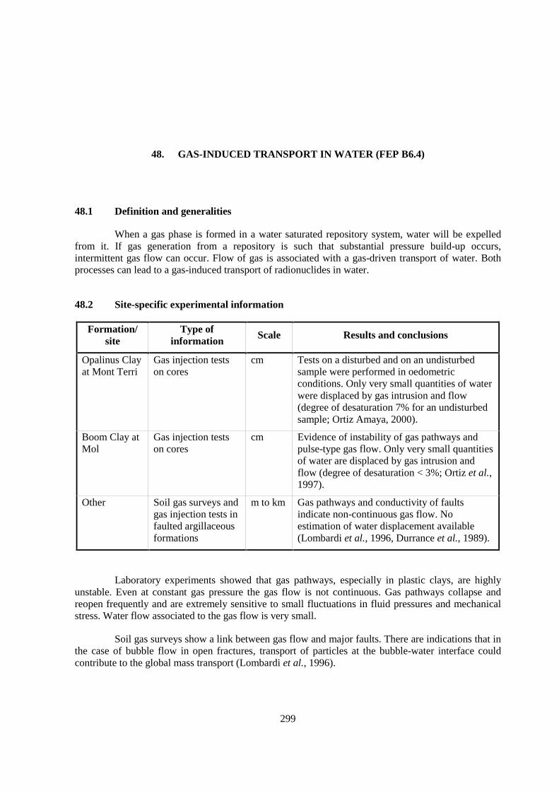
299
48. GAS-INDUCED TRANSPORT IN WATER (FEP B6.4)
48.1 Definition and generalities
When a gas phase is formed in a water saturated repository system, water will be expelledfrom it. If gas generation from a repository is such that substantial pressure build-up occurs,intermittent gas flow can occur. Flow of gas is associated with a gas-driven transport of water. Bothprocesses can lead to a gas-induced transport of radionuclides in water.
48.2 Site-specific experimental information
Formation/site
Type ofinformation
Scale Results and conclusions
Opalinus Clayat Mont Terri
Gas injection testson cores
cm Tests on a disturbed and on an undisturbedsample were performed in oedometricconditions. Only very small quantities of waterwere displaced by gas intrusion and flow(degree of desaturation 7% for an undisturbedsample; Ortiz Amaya, 2000).
Boom Clay atMol
Gas injection testson cores
cm Evidence of instability of gas pathways andpulse-type gas flow. Only very small quantitiesof water are displaced by gas intrusion andflow (degree of desaturation < 3%; Ortiz et al.,1997).
Other Soil gas surveys andgas injection tests infaulted argillaceousformations
m to km Gas pathways and conductivity of faultsindicate non-continuous gas flow. Noestimation of water displacement available(Lombardi et al., 1996, Durrance et al., 1989).
Laboratory experiments showed that gas pathways, especially in plastic clays, are highlyunstable. Even at constant gas pressure the gas flow is not continuous. Gas pathways collapse andreopen frequently and are extremely sensitive to small fluctuations in fluid pressures and mechanicalstress. Water flow associated to the gas flow is very small.
Soil gas surveys show a link between gas flow and major faults. There are indications that inthe case of bubble flow in open fractures, transport of particles at the bubble-water interface couldcontribute to the global mass transport (Lombardi et al., 1996).

300
48.3 Scaling issues
Upscaling of experimental findings from the laboratory and borehole scales to the scale ofthe formation and the waste repository is very difficult.
48.4 Scientific level of understanding
Although the fundamental processes are rather well understood, understanding is stillinsufficient for large (repository) scale modelling and parametrisation.
48.5 Linked FEPs
FEP 3 Migration pathways, including heterogeneity and anatomy
FEP 6 Hydraulic properties of the host rock
FEP 37 Geomechanical rock properties
FEP 38 Hydraulic properties of the EDZ
FEP 39 State of saturation of the EDZ and desiccation cracking
FEP 42 Self-sealing
FEP 46 Gas migration through the primary porosity (matrix, natural fractures)
FEP 47 Gas migration through stress-induced porosity (gas fracs, pathway dilation)
FEP 55 Present-day stress regime
48.6 Level of understanding from a PA perspective and treatment in PA
When a gas phase is formed in a water saturated repository, pressures develop and water willbe expelled. This water can be contaminated if the waste packages are already being leached. Thepotential of the whole process to increase radionuclide transport from a repository depends on therelative kinetics of the resaturation of the repository after closure, the evolution of the structure andpermeability of the EDZ, the rate of gas generation, the rate at which waste containers start to leak andthe leaching rate of leaky containers. The coupling between these processes makes the modelling orthe assessment of their global influence on radionuclide transport complex.
Examples of the treatment of gas-induced radionuclide transport in water in PA can be foundin NEA (2001). In general, these assessments are performed in a simplified conservative way, in orderto assess the potential for an increased radionuclide transport. Under some very site-specificcombinations of the mentioned processes, an increase in the transport of some radionuclides ispossible. However, the influence on the overall repository system is low.
48.7 Available reviews
NEA(2001), Rodwell et al. (1999).
301
48.8 Planned work
At EC level, the thematic network GASNET was started to discuss how to treat gas issues insafety assessment.
48.9 Overall evaluation
In principle, gas-induced transport of water can increase the radionuclide flux to thebiosphere, because this process can short-cut the barrier function of argillaceous host rocks. Thereforeit is a highly relevant FEP. The quantitative evaluation of this FEP is very complex due to the couplingwith hydro-mechanical, gas-generation and waste-leaching processes. Detailed modelling is currentlynot possible due to the difficulty of upscaling experiments to repository level and due to the lack ofreliable large-scale models and parameters. However, preliminary assessments indicate that the overalleffect on repository safety would be rather small or even negligible.

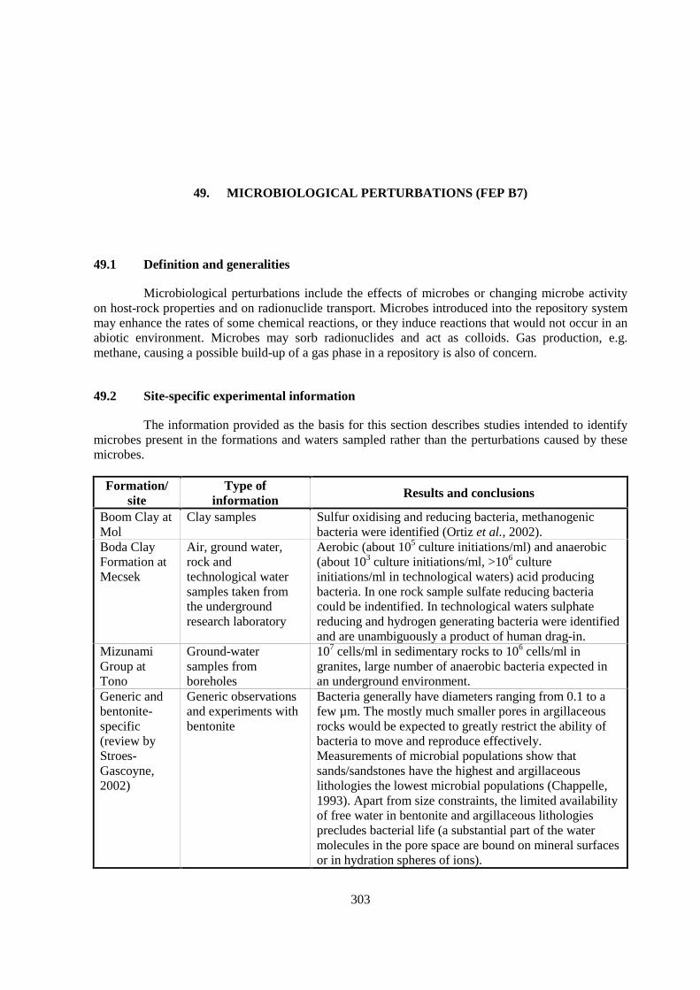
303
49. MICROBIOLOGICAL PERTURBATIONS (FEP B7)
49.1 Definition and generalities
Microbiological perturbations include the effects of microbes or changing microbe activityon host-rock properties and on radionuclide transport. Microbes introduced into the repository systemmay enhance the rates of some chemical reactions, or they induce reactions that would not occur in anabiotic environment. Microbes may sorb radionuclides and act as colloids. Gas production, e.g.methane, causing a possible build-up of a gas phase in a repository is also of concern.
49.2 Site-specific experimental information
The information provided as the basis for this section describes studies intended to identifymicrobes present in the formations and waters sampled rather than the perturbations caused by thesemicrobes.
Formation/site
Type ofinformation Results and conclusions
Boom Clay atMol
Clay samples Sulfur oxidising and reducing bacteria, methanogenicbacteria were identified (Ortiz et al., 2002).
Boda ClayFormation atMecsek
Air, ground water,rock andtechnological watersamples taken fromthe undergroundresearch laboratory
Aerobic (about 105 culture initiations/ml) and anaerobic(about 103 culture initiations/ml, >106 cultureinitiations/ml in technological waters) acid producingbacteria. In one rock sample sulfate reducing bacteriacould be indentified. In technological waters sulphatereducing and hydrogen generating bacteria were identifiedand are unambiguously a product of human drag-in.
MizunamiGroup atTono
Ground-watersamples fromboreholes
107 cells/ml in sedimentary rocks to 106 cells/ml ingranites, large number of anaerobic bacteria expected inan underground environment.
Generic andbentonite-specific(review byStroes-Gascoyne,2002)
Generic observationsand experiments withbentonite
Bacteria generally have diameters ranging from 0.1 to afew µm. The mostly much smaller pores in argillaceousrocks would be expected to greatly restrict the ability ofbacteria to move and reproduce effectively.Measurements of microbial populations show thatsands/sandstones have the highest and argillaceouslithologies the lowest microbial populations (Chappelle,1993). Apart from size constraints, the limited availabilityof free water in bentonite and argillaceous lithologiesprecludes bacterial life (a substantial part of the watermolecules in the pore space are bound on mineral surfacesor in hydration spheres of ions).
304
Bacterial effects are not well studied, and the experimental data base is very small. Inargillaceous rocks, the pore sizes in the matrix are often too small for organisms, with the possibleexception of faults and fractures. However, bacteria are most likely present in the affected field whereopen spaces of adequate size may be abundant. It is difficult to determine whether they were originallypresent or introduced due to the excavation works. Generally, molecular (e.g. PCR) techniques showthat many more genera of micro-organisms are present than can be cultivated.
49.3 Scaling issues
None reported.
49.4 Scientific level of understanding
During construction and operation, the whole repository will be contaminated with a widevariety of micro-organisms. Some of these can survive under very harsh conditions. Little is knownabout what will happen during the transient phase when the geochemical system evolves from anaerobic to an anaerobic atmosphere. It is however clear that when micro-organisms have very littleaccess to space and nutrients, their activity and mobility will be very limited.
49.5 Linked FEPs
FEP 9 Connected matrix porosity
FEP 15 Natural organics, complexation
FEP 17 Pore- and fracture water composition
FEP 30 Organics from waste and their effect on transport properties of the host rock
FEP 42 Self-sealing
49.6 Level of understanding from a PA perspective and treatment in PA
From a PA perspective, the importance of bacterial activity is mainly related to the influenceon gas generation by bacterial degradation of organic materials in medium-level waste, the chemistryof the affected field and the possible influence on container corrosion. From the point of view ofradionuclide migration in the host rock, micro-organisms probably play a very limited role due to thesmall pore size in argillaceous formations and the limitation of mass transport to the diffusionmechanism in several (but not all) argillaceous systems.
In actual PAs, this FEP has been only considered in connection to gas generation to date.
49.7 Available reviews
None reported.
305
49.8 Planned work
An experiment dealing with microbiology is planned for the coming investigation phase(2003-2004) in the Mont Terri underground research laboratory.
49.9 Overall evaluation
Issue important for gas generation from organic materials in medium-level waste. Very littleis known about this FEP, and there is no consensus on its (ir)relevance.

307
50. PAST BURIAL HISTORY (FEP C1.1.3)
50.1 Definition and generalities
Burial history includes all events and processes that affected a formation since the time ofsedimentation. In specific, it includes vertical movements (burial, uplift), compaction and expulsion ofpore-water, diagenesis, stress and thermal history, and deformation events.
50.2 Site-specific experimental information
Formation/site Results and conclusions
Callovo-Oxfordian atBure
The formation was subjected to burial throughout the Mesozoic, with only minoreffects of uplift since the Tertiary. Maximum temperatures in the formation areestimated at 50°C.
Toarcian-Domerian atTournemire
Since sedimentation, the Jurassic and Early Cretaceous evolution was characterisedby extension and subsidence of the basin. Calcite veins precipitated during thisperiod. This stage was followed by a basin inversion that began 90-110 Ma b.p. andled to the erosion of 800-1600 m of Cretaceous sediments. A compressive stageoccurred during the Eocene (Pyrenean orogeny).
Temperature history was reconstructed by the study of fluid-inclusions, Rock-Evalpyrolysis of organic matter, apatite fission tracks and clay mineralogy. Maximumtemperatures during burial are estimated at 80-120°C. Calcite veins that crystallisedduring the Pyrenean stage indicate temperatures of formation of 30-40°C (evidencefrom fluid inclusions).
Reference: Peyaud (2002).
OpalinusClay at MontTerri
Similar to the Zürcher Weinland, Opalinus Clay at Mont Terri experienced a two-stage burial and uplift history (Nagra 2002). The first burial occurred in theCretaceous and resulted in an estimated overburden of 1 350 m and temperaturescomparable to those of the Zürcher Weinland (see below). The second, Mioceneburial event was more weakly developed than in the Zürcher Weinland (estimateddepth of Opalinus Clay ca. 1 000 m) because less deposition of Molasse sedimentsoccurred. However, major uncertainties regarding the thickness of (now eroded)Cretaceous and early Tertiary sediments remain. Thus unlike in the ZürcherWeinland, the first, Cretaceous burial at Mont Terri resulted in both maximumburial and maximum temperature ever experienced by the formation.
308
Formation/site Results and conclusions
In detail, the Tertiary evolution can be described as follows (Wermeille & Bossart1999):
• In the early Oligocene (37-28 Ma), the area is under shallow marine conditions(Lower Marine Molasse). Formation of N-S faults east of St. Ursanne andcreation of the Mont Terri flexure (in the context of the Rhine Graben).
• Continued subsidence of the Delémont basin, deposition of the Lower Fresh-water Molasse (lacustrine and river sediments, 28-21.5 Ma).
• Continued subsidence between 21.5 and 10.5 Ma. The area around St. Ursanneis emerged and hydrologically separated from the Delémont Basin. Starting ofthe erosive period and formation of the Doubs river valley.
• The folding of the Jura Mountains occurs in the period 10-3 Ma and is relatedto uplift and erosion. Aquifers above and below the Opalinus Clay startreceiving modern recharge.
• Eight glaciation phases between 2 Ma and 13 000 a occurred. The front of themaximum glaciation, which occurred 780 000 a b.p., lies about 10 km south ofSt. Ursanne.
OpalinusClay in theZürcherWeinland
A number of different techniques were used to characterise the burial andtemperature history of the sedimentary rocks of the Zürcher Weinland, includingstudies of stratigraphy, fluid inclusions, clay mineralogy, petrography of cements,vitrinite reflectance, biomarkers (incl. pyrolysis experiments), fission tracks inapatite, shale compaction and basin modelling (Nagra, 2002).
Stratigraphic evidence suggests that the Opalinus Clay was subjected to twosuccessive events of burial and uplift, and it is currently over-consolidated (OCR =1.5-2.5). Basin models were used to integrate stratigraphic evidence with otherdata, in specific fission-track analysis of apatite and biomarker maturity, andindicate that maximum temperature (ca. 85°C) was attained during the first,Cretaceous burial event, while maximum depth (ca. 1 700 m below surface) andtherefore maximum compaction was reached during the much shorter Mioceneevent (ca. 10 Ma b.p.). The two events were separated by an uplift phase where ca.600 m of the overlying sedimentary rocks were eroded. Since maximum burial, theregion of interest has been (and still is) uplifting at an average rate of 0.1 mm/a.
Boom Clayat Mol
Very detailed information exists on the entire Cenozoic stratigraphic column thanksto a series of boreholes. The precision of the parameters obtained along thestratigraphic column is in the order of decimetres. This allows reconstituting burialhistory with high precision (sequential stratigraphy). In the geological past, theBoom Clay at Mol appears to never have been deeper in the geological past than atthe present day, in contrast to the Antwerpen region (Van Keer & de Craen, 2001).However, from a geomechanical point of view, in situ measurements show that theBoom Clay at Mol is over-consolidated. At present no explanation for thisphenomenon exists (see also FEP 58).
309
Formation/site Results and conclusions
Boda ClayFormation atMecsek
After the deposition of the Boda Clay Formation, sedimentation and subsidencecontinued to the Early Jurassic, resulting in an overburden of 3 500-5 000 m.During the Jurassic, the sedimentary facies changed from shallow-water to pelagic,but the thickness of the sediments was only some hundreds of metres. Uplift startedin the Cretaceous, and there is no record of younger sediments. In summary, themaximum burial of the Boda Clay Formation is estimated at 4 000-5 000 m on thebasis of stratigraphic evidence.
On the basis of illite and chlorite crystallinity and of vitrinite reflectance, maximumtemperature experienced by the formation is estimated at 200-250°C. K/Ar ages ofillite (fraction <2 µm) yield 197 ± 10 Ma (Early Jurassic), which is interpreted asthe date of maximum burial.
Pierre Shalein southDakota
Geologic reconstructions of central South Dakota based on erosional remnants andsedimentological considerations indicate that ca. 400 m of overburden sedimenthas been eroded at the Hayes site in a series of lateral river erosion episodes(Neuzil 1993). Prior maximum overburden on the Pierre Shale at Hayes (SouthDakota) was estimated from consolidation tests on cores using Casagrande method.This approach suggested as much as one km or more of overburden was erodedfrom the site (Neuzil, 1993).
50.3 Scaling issues
Burial and uplift are processes that occur on the scale of the sedimentary basin, i.e. on aregional scale. Samples on which burial and temperature histories are investigated typically come fromboreholes. In most examples studied here, the results can be inter- or extrapolated to a larger area(mostly >10 km away from the investigation site) because lateral changes of the thickness of theoverlying sediments or amounts of erosion do not change dramatically over such distances. Majordifferential vertical movements during burial and uplift would be expected to occur along regionalfaults, whose existence and position would be identified by regional field investigations (fieldmapping, seismics).
50.4 Scientific level of understanding
A substantial number of independent methods exist to constrain burial and temperaturehistory. If these are used in combination, even complex geologic evolutions, such as in Opalinus Clay(two-stage burial and uplift, erosional gaps), can be reasonably well constrained and result in goodsystem understanding. The important point is not to use individual methods in isolation but to integratethem, e.g. in basin models. Such models couple the burial and temperature histories and also provide aconsistency check of the methods applied.
310
50.5 Linked FEPs
FEP 5 Hydraulic potentials and gradients in the host rock, including boundary conditions
FEP 14 Lithology, mineralogy of rocks and fracture infills
FEP 53 Past deformation events
50.6 Level of understanding from a PA perspective and treatment in PA
Burial and temperature history play a role in different aspects of PA:
• The knowledge of burial or uplift rates over long time scales (e.g. several Ma) can beextrapolated into the future and be used e.g. for erosion scenarios. It can also becompared to vertical movements derived from levelling data spanning time scales ofyears to decades.
• Maximum burial depth is needed to calculate important geomechanical parameters, suchas the over-consolidation ratio, some of which are useful in rock-mechanical conceptualmodels.
• Effects experienced by the formation during its natural evolution can be comparedquantitatively with expected repository-derived effects. For example, the thermal pulsederived from high-level waste can be put into perspective by comparison with themaximum temperature during burial, and this facilitates the estimation of possibleconsequences of the thermal pulse.
• In many cases, data and evidence from occurrences of the host formation outside thetarget area are used in a performance assessment (e.g. data from Mont Terri are used inthe Swiss PA for Opalinus Clay in the Zürcher Weinland). Burial history needs to beknown over the whole region, in order to build a basis for the extrapolation of externaldata into the target area.
The methods to constrain burial history are manifold and well developed. Burial history isconsidered as relevant but also well understood in most cases.
50.7 Available reviews
None reported.
50.8 Planned work
None reported.
50.9 Overall evaluation
Burial history affects several PA-relevant parameters and conceptual models and isconsidered relevant. A substantial number of methods constraining basin evolution are available andlead, if applied in an integrative manner, to a good understanding.
311
51. PRESENT AND FUTURE GEOTHERMAL REGIMEAND RELATED PROCESSES (FEP C1.2.1)
51.1 Definition and generalities
The geothermal regime is determined by the natural flux of heat from deep crustal and mantle rockto the surface. The surface temperature is established by local climatic conditions. The thermalgradient depends predominantly on the surface temperature, the geothermal heat flux and the thermalconductivity of the rock column. Locally, thermal gradients can be perturbed by advective heattransfer in flowing ground water. Within argillaceous formations, only heat transfer by conduction(diffusion) is to be expected. This FEP is relevant to the far field in connection with sitecharacterisation and boundary conditions for affected-field processes.
51.2 Site-specific experimental information
Site-specific geothermal gradients can be determined by temperature measurements inboreholes. The thermal conductivity and capacity values for specific formations are based onlaboratory and field measurements. Values for representative formations are given in FEP 32.
51.3 Scaling issues
None reported. Geothermal gradient measurements are on the local scale. Scaling problemswith thermal rock properties are discussed in FEP 32.
51.4 Scientific level of understanding
The principles of heat transfer in natural material are well understood. Mathematicalmodelling tools for describing temperature regimes and their changes in response to changing thermalconditions are widely available.
51.5 Linked FEPs
FEP 32 Thermal rock properties
FEP 50 Past burial history
312
51.6 Level of understanding from a PA perspective and treatment in PA
Consideration of the geothermal regime is more likely to be an aspect of scenario analysisthan part of a comprehensive PA model. Substantial changes in the geothermal regime, e.g. by theintrusion of a heat source (igneous sill or dike) at depth, are not expected over the time scales in theorder of 1 Ma, so this FEP is not of prime importance.
Andra and SCK•CEN have modelled the geothermal regime under climatic conditions thatwould promote permafrost formation. This modelling indicates that the depth of the 0ºC isothermwould reach 300 m at Andra's Bure site but would not reach the depth of the Boom Clay at Mol.
51.7 Available reviews
Textbooks on geothermal systems or on the transport of heat and other substances in naturalsystems provide a background which is sufficient for the description and modelling of the geothermalregime.
51.8 Planned work
None reported.
51.9 Overall evaluation
In assessing the performance of an argillaceous site, it may be important to consider changesin the thermal regime if scenario analysis indicates the site could be subjected to changing thermalboundary conditions such as volcanic intrusions or serious changes in climatic conditions at thesurface.
313
52. FUTURE CHANGES IN HYDROCHEMISTRY OF THE HOST ROCK AND OFSURROUNDING FORMATIONS (E.G. DUE TO OUT-DIFFUSION,
WATER-ROCK INTERACTIONS, UPLIFT) (FEP C1.2.2)
52.1 Definition and generalities
This FEP refers to the changes in fluid chemistry due to the following effects:
• Uplift during the long-term evolution could bring about erosion of overlying strataexposing the host rock and surrounding units to new sources and types of recharge, orcould open new discharge points easing the flow of water through the host rock oradjacent formations. Changing recharge could be of different chemistry, and increasedwater flow could bring about chemical changes by facilitating redox and other water-rock reactions.
• Diagenetic processes affecting the long-term evolution of the site region include theintrusion of saline or oxidising waters which could establish new boundary conditionsfor chemical reactions, flow and diffusion within the host rock and the repositoryenvironment. Such changes should be explored for possible inclusion in scenariosconsidered for PA.
52.2 Site-specific experimental information
Formation/site Results and conclusions References
Opalinus Clayat Mont Terri
The effect of uplift on the chemistry of pore-water is known. It isdiscussed in detail in FEPs 23-25.
Pearson et al.(2003)
Opalinus Clayin the ZürcherWeinland
Solutes not controlled by water-rock interaction, such as Cl, Brand SO4, will diffuse out of the Opalinus Clay, thereby reducingoverall salinity. This process has been initiated ca. 2-2.5 Ma agoby the infiltration of low-salinity water into the local Keuperaquifer and is currently ongoing. The reduction of Cl content isaccompanied by a corresponding reduction of Na content. Over atime period of 1 Ma, the reduction of salinity will be <10%.
Nagra (2002)
Boom Clay atMol
The last significant change was seawater transgression some1.6 Ma ago. Since that time, the Campine Basin has evolvedfrom a marine to a continental environment, and fresh waterstarted to infiltrate into the aquifers surrounding the Boom Clay.At present, the average Cl concentration in the Boom Clay atMol is as low as 28 mg/l.

314
52.3 Scaling issues
Interpretation of water chemical changes is on the scale of the formation, thus suited for PApurposes. However, the available data base often refer to much shorter periods of time.
52.4 Scientific level of understanding
The chemical composition of pore-water in argillaceous formations is affected by thetemporal evolution of ground waters in the embedding aquifers. In many cases, the past evolution ofthe ground waters can be used for extrapolations into the future. At least in the case of diffusion-dominated argillaceous formations, exchange rates will be slow and can often be predicted withconfidence. For the Opalinus Clay, a well supported quantitative model is available.
52.5 Linked FEPs
FEP 7 Units over- and underlying the host formation: local and regional hydrogeologic framework
FEP 8 Diffusivity
FEP 14 Lithology, mineralogy of rocks and fracture infills
FEP 18 Dissolution / precipitation of solid phases
FEP 20 Ion exchange
FEP 22 Thermodynamic and kinetic modelling data
FEP 24 Evolution of pore-fluid (water and gas) chemistry and mineralogy in the host formation andin embedding units
FEP 25 Water residence times in the host formation
FEP 27 Redox buffering capacity of the host rock
FEP 50 Past burial history
FEP 54 Future fault (re)activation, changes in migration pathways; changes of hydraulic parameters;flow events
52.6 Level of understanding from a PA perspective and treatment in PA
As long as diffusion remains the dominant transport mechanism, this FEP is well understoodquantitatively and of little relevance. The chemical changes due to diffusion are slow enough to beneglected over PA-relevant time scales. Existing uncertainties with respect to the chemical evolutionof the embedding aquifers (e.g. salt water intrusion) can be covered by alternative scenarios in PA.
In fractured, advection-dominated systems, the chemical interaction between aquifers andhost formation my be more rapid and spatially more heterogeneous. A good understanding of the flowsystem is required.
52.7 Available reviews
None reported.

315
52.8 Planned work
None reported.
52.9 Overall evaluation
This FEP will have minimal effect on repository performance even over long time scalesprovided diffusion remains the dominant transport mechanism between the argillaceous unit andadjacent formations. Should fracture flow be an important transport mechanism, the effects would bemore rapid.

317
53. PAST DEFORMATION EVENTS (FEP C2.1)
53.1 Definition and generalities
Non-elastic deformations and the associated formation of natural fractures occurred inresponse to vertical movements in the sedimentary basin (burial, inversion) and/or to regional tectonicstresses (see also FEPs 2 and 3). Purely extensional structures (joints) are not very frequent inargillaceous media, except in highly indurated formations and in near-surface environments. By far themost relevant large-scale structures are faults, i.e. normal faults, thrusts and strike-slip faults.
While faults may not be active migration pathways over geological periods of time, fluid-flow events may occur during active faulting. Different deformation events may reactivate alreadyexisting structures, resulting in recurrent phases of fluid flow along faults. While these findings arewell established in more permeable rocks, such as crystalline basement or sandstone, the importanceof episodic flow along faults in argillaceous formations is not entirely clear, however most likely quitelimited (FEP 54).
53.2 Site-specific experimental information
The occurrence and geometry of faults on a wide range of scales is described in FEPs 2 and3. Among the formations considered here, those which did not experience major burial and inversionand therefore are weakly indurated (Boom Clay and Spanish Reference Clay) show only a low densityof faults and fractures. On the other hand, highly indurated (i.e. deeply buried) formations, such as theBoda Clay Formation and the Palfris Formation at Wellenberg, are highly faulted and contain fracturenetworks of different origins and ages.
In the sedimentary basin of northern Switzerland, seismic evidence indicates that severaldeformation events occurred during the Mesozoic, and this is evident from the fact that the density ofstructures decreases with age (Birkhäuser et al., 2001). For example, the top of the Opalinus Clayshows less features than its base, which argues for synsedimentary tectonics. The tectonic andneotectonic situation is addressed in Müller et al. (2002).
Fluid flow related to faulting can be recorded by fracture infills and/or wall-rock alterationsalong fractures. In the weakly indurated formations that were considered (Boom Clay, SpanishReference Clay, Callovo-Oxfordian at Bure, Opalinus Clay), fracture mineralisations and veins areabsent or very scarce. Their absence is taken as evidence of the lack of major fluid flow alongfractures during and after faulting. In the Toarcian-Domerian at Tournemire, geodic calcite veins occurin dilatant parts of faults (Boisson et al., 1998). In the Boda Clay Formation and in the PalfrisFormation at Wellenberg, fracture infills are abundant and mostly related to events that occurredduring deep burial of the formations. At Wellenberg, vein infills can be explained by local (m-scale)mass redistribution due to pressure solution and re-precipitation in pressure shadows (Mazurek, 1999).
318
53.3 Scaling issues
Natural non-elastic deformations result in structures on a wide range of scales, and differentinvestigation methods provide data on different scales (see FEP 3 for details). The temporal scalesover which the information relates are comparable, often even much longer than those required for PApredictions.
53.4 Scientific level of understanding
The understanding of geometric aspects of deformation events that occurred in thegeological past is generally very good, with the exception of steeply dipping structures at sites whereonly vertical boreholes are available. On the other hand, in many cases it is difficult to date thedeformation events. Events of fluid flow related to deformation events can be reconstructed on thebasis of fracture mineralogy and geochemistry. The absence of mineralogical and geochemicalevidence for fluid-flow events is a necessary but not sufficient argument for the extrapolation of thepresent-day situation to the future.
Formations that were deeply buried (several km) are often fractured, faulted and containabundant veins and fracture infills. In most cases, faulting and mineralisation occurred at depth, atpressure-temperature conditions that are substantially different from present-day conditions andconditions expected for the future. Care must be taken to use only those features and processesobserved in the rocks for extrapolations that are relevant for the physico-chemical conditions expectedover PA-relevant time scales.
53.5 Linked FEPs
FEP 2 Size and geometry of the host rock and of surrounding units, migration path length
FEP 14 Lithology, mineralogy of rocks and fracture infills
FEP 37 Geomechanical rock properties
FEP 50 Past burial history
53.6 Level of understanding from a PA perspective and treatment in PA
Knowledge of past non-elastic deformation events contributes to general systemunderstanding, which is needed for the prediction of such deformations that may occur in future.While the deformation events themselves are of limited PA relevance, possible fluid-flow eventsassociated to these deformations may be included in alternative PA scenarios of long-term evolution(FEP 54).
The attractiveness in studying past deformations lies in the fact that geological deformationstructures occurring in the rocks today reflect the integrated history of the formation over geologicaltime scales. Even if no major active deformation takes place at the present time (as evidenced e.g. byneotectonic surveys), evidence of past faulting events can be integrated in scenario development forPA.
319
53.7 Available reviews
None reported.
53.8 Planned work
None reported.
53.9 Overall evaluation
Faults and fractures in the rocks record the integrated effects of deformations over geologicaltime scales. Deformations that can be expected in the future can be constrained by studying theevolution in the past.

321
54. FUTURE FAULT (RE)ACTIVATION, CHANGES IN MIGRATION PATHWAYS;CHANGES OF HYDRAULIC PARAMETERS; FLOW EVENTS (FEP C2.2)
54.1 Definition and generalities
In a dynamic natural system, stresses accumulate over long periods of time and may beinstantaneously released in earthquakes. Such events of fault movement may change migrationpathways, permeabilities, head distributions and thus result in flow events.
54.2 Site-specific experimental information
Formation/site
Results and conclusions
Paris Basin(includingthe Callovo-Oxfordian atBure)
The effects of permafrost on the hydrogeological evolution (mainly headdistribution) have been studied by means of numerical simulations. The resultsindicate that the effects may not be completely irrelevant (slight increase of I doses;possibly less dilution in aquifers).
OpalinusClay innorthernSwitzerland
In spite of the presence of major faults in Opalinus Clay, these are not associatedwith mineralisations and alterations and thus do not show any evidence of fluid-flow events related to faulting. Profiles of tracers in pore-water in the Benkenborehole and at Mont Terri can be explained by diffusion and do not record anyrelationship to faults. Fluid flow related to seismicity in Opalinus Clay is discussedin Hicks (2002).
Boom Clayin NEBelgium
Active faults can be traced on the surface as escarpments. In NE Belgium, severalactive faults belonging to the Roer Valley Graben were studied by means of directobservation in trenches, by several geophysical methods (electrical tomography,high-resolution reflection seismics, boreholes) and by the study of the seismicactivity. Studies of recent earthquakes give information about the depth of themovement and the displacement that took place (Ahorner, 1992).
Boda ClayFormation atMecsek
Regional uplift is slow, and the generation of new faults is not expected in the next1 Ma. However, a compressive regime has persisted over millions of years,witnessed by folding and thrusting of Pliocene sediments along existing (i.e.reactivated) faults. Fault (re)activation in the future is expected mainly along themargin of the Mecsek Mountains.
MizunamiGroup atTono
The steeply dipping Tsukiyoshi fault indicates 30 m of reverse movement and isobserved to cut early to middle Miocene sediments interbedding with the severalshale layers in the Tono mine. The fault is estimated to have been most active inthe period 15 to 5 Ma (Koide et al., 1996).
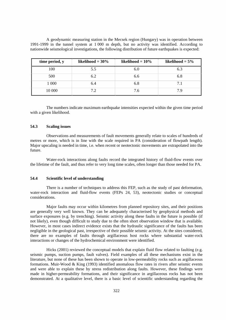
322
A geodynamic measuring station in the Mecsek region (Hungary) was in operation between1991-1999 in the tunnel system at 1 000 m depth, but no activity was identified. According tonationwide seismological investigations, the following distribution of future earthquakes is expected:
time period, y likelihood = 30% likelihood = 10% likelihood = 5%
100 5.5 6.0 6.3
500 6.2 6.6 6.8
1 000 6.4 6.8 7.1
10 000 7.2 7.6 7.9
The numbers indicate maximum earthquake intensities expected within the given time periodwith a given likelihood.
54.3 Scaling issues
Observations and measurements of fault movements generally relate to scales of hundreds ofmetres or more, which is in line with the scale required in PA (consideration of flowpath length).Major upscaling is needed in time, i.e. when recent or neotectonic movements are extrapolated into thefuture.
Water-rock interactions along faults record the integrated history of fluid-flow events overthe lifetime of the fault, and thus refer to very long time scales, often longer than those needed for PA.
54.4 Scientific level of understanding
There is a number of techniques to address this FEP, such as the study of past deformation,water-rock interaction and fluid-flow events (FEPs 24, 53), neotectonic studies or conceptualconsiderations.
Major faults may occur within kilometres from planned repository sites, and their positionsare generally very well known. They can be adequately characterised by geophysical methods andsurface exposures (e.g. by trenching). Seismic activity along these faults in the future is possible (ifnot likely), even though difficult to study due to the often short observation window that is available.However, in most cases indirect evidence exists that the hydraulic significance of the faults has beennegligible in the geological past, irrespective of their possible seismic activity. At the sites considered,there are no examples of faults through argillaceous host rocks where substantial water-rockinteractions or changes of the hydrochemical environment were identified.
Hicks (2001) reviewed the conceptual models that explain fluid flow related to faulting (e.g.seismic pumps, suction pumps, fault valves). Field examples of all these mechanisms exist in theliterature, but none of these has been shown to operate in low-permeability rocks such as argillaceousformations. Muir-Wood & King (1993) identified anomalous flow rates in rivers after seismic eventsand were able to explain these by stress redistribution along faults. However, these findings weremade in higher-permeability formations, and their significance in argillaceous rocks has not beendemonstrated. At a qualitative level, there is a basic level of scientific understanding regarding the
323
hydrogeological consequences of fault (re)activation, but the scientific level of understanding at amore detailed, quantitative level is low.
54.5 Linked FEPs
FEP 3 Migration pathways, including heterogeneity and anatomy
FEP 7 Units over- and underlying the host formation: local and regional hydrogeologic framework
FEP 14 Lithology, mineralogy of rocks and fracture infills
FEP 23 Palaeo-hydrogeology of the host formation and of embedding units
FEP 24 Evolution of pore-fluid (water and gas) chemistry and mineralogy in the host formation andin embedding units
FEP 25 Water residence times in the host formation
FEP 37 Geomechanical rock properties
FEP 56 Future stress regime
FEP 57 Geomechanical effects of erosion/unloading
54.6 Level of understanding from a PA perspective and treatment in PA
In many PA studies, the (re)activation of faults, followed by transient or stationary fluidflow, is studied in what if scenarios. Except in highly indurated formations where fracture flow isimportants, this FEP is considered as not very relevant and so is not treated in the base case of PAstudies.
For the Boom Clay at Mol, the potential effect of a fault zone has been assessed in the PAstudy of Marivoet (1988). The assessment shows that the effect was not very relevant. Due to thecreep of the Boom Clay, no open faults can be maintained but a zone with non-elastic deformation canbe formed. Mechanical damage to the repository due to faulting can be excluded because therepository will be located outside of existing faults (such areas exist and can be explored).
54.7 Available reviews
Boom Clay: Demyttenaere (1988), Langenaeker (1998).
54.8 Planned work
Boom Clay at Mol: The digging of a trench is foreseen, in order to study the activity of theclosest faults near to the site. The observations will take place during 2003, the studies finalised byearly 2004.
Boda Clay Formation at Mecsek: Long-term leveling using the GPS measurement network isforeseen, consisting of 9 points and starting in 2000. A measurement was already done in 1998, on anetwork consisting of 8 points. A geodynamic measuring station consisting of a long extensometerwas installed at 80 m depth in 2000 in an area where the Boda Clay Formation crops out, and wascomplemented by 3 short extensometers installed perpendicular to each other. The measurement series
324
is planned for the long term and is done with continuous, automatic data recording. Its purpose is thecharacterisation of the three-dimensional deformation within the Western Mecsek Anticline.
54.9 Overall evaluation
The importance of this FEP is regarded to be relatively small because the positions of majorfaults are generally well known and there is no clear field evidence that faulting is related to majorfluid-flow events in argillaceous rocks. In the Belgian assessment, even if a fault activation creates afault that touches the repository, the fraction of radionuclides that can migrate through this fault isvery small.
325
55. PRESENT-DAY STRESS REGIME (FEP C2.5)
55.1 Definition and generalities
The present-day stress regime is a basic attribute of the host rock and is intrinsically relatedto its geological and geomorphological setting. It constitutes an essential component in the repositorysystem. As boundary condition it is an indispensable factor in the setup of a geomechanical model forthe numerical analysis of the system.
Present-day in situ stress of the host rock is relevant predominantly for the following tworeasons:
1. In the far field it is a controlling factor in the layout of the underground works. In the case,for instance, that the maximum horizontal in situ stress σH is greater than the vertical stressσv, the emplacement tunnels and galleries are optimally oriented if they are aligned in thedirection of σH.
2. In the affected field it controls, amongst others, the shape and extent of the EDZ, the groundsupport required and the layout of the engineered barrier system.
The term “present-day stress regime” is generally understood as the state of stress which iscurrently acting in a geological formation without any man-induced disturbances. It is also termed“primary”, “geologic”, “virgin”, “in situ” or “initial” state of stress.
In general terms, the 3-D state of stress at a point is specified by six components (threenormal stress and three shear stress components). Alternatively, the state of stress may be described interms of three principal stresses σ1, σ2 and σ3, with σ1 being termed the major, σ2 the intermediate andσ3 the minor principal stress (σ1 ≥ σ2 ≥ σ3; compression positive). Each principal stress is defined byits magnitude and orientation (Brady and Brown, 1985). The orientation of the three principal stressesis normal to each other, i.e. the orientations constitute units which are not entirely independent of eachother. Very common is the consideration of the normal stress components which are acting in vertical(σv) and in distinct horizontal directions (σH and σh with σH being the major and σh the minorhorizontal normal stress component). Particularly, in connection with stress measuring tests in verticalboreholes based on hydraulic fracturing, it is (often tacitly) assumed that σv, σH and σh are principalstresses.
In an actual project situation it may be possible to roughly estimate the order of magnitude ofthe primary in situ principal stresses and their orientations from observations of so-called “stressindicators” and knowledge of the general morphological and geologic setting. However, theuncertainty of the actual values is substantial in the absence of direct measurements (Goodman, 1980).In rock engineering practice, the question of the present-day state of stress therefore is intrinsicallyconnected with in situ stress measurements and with site-specific observations, e.g. of the breakoutconfigurations in boreholes or in underground openings.
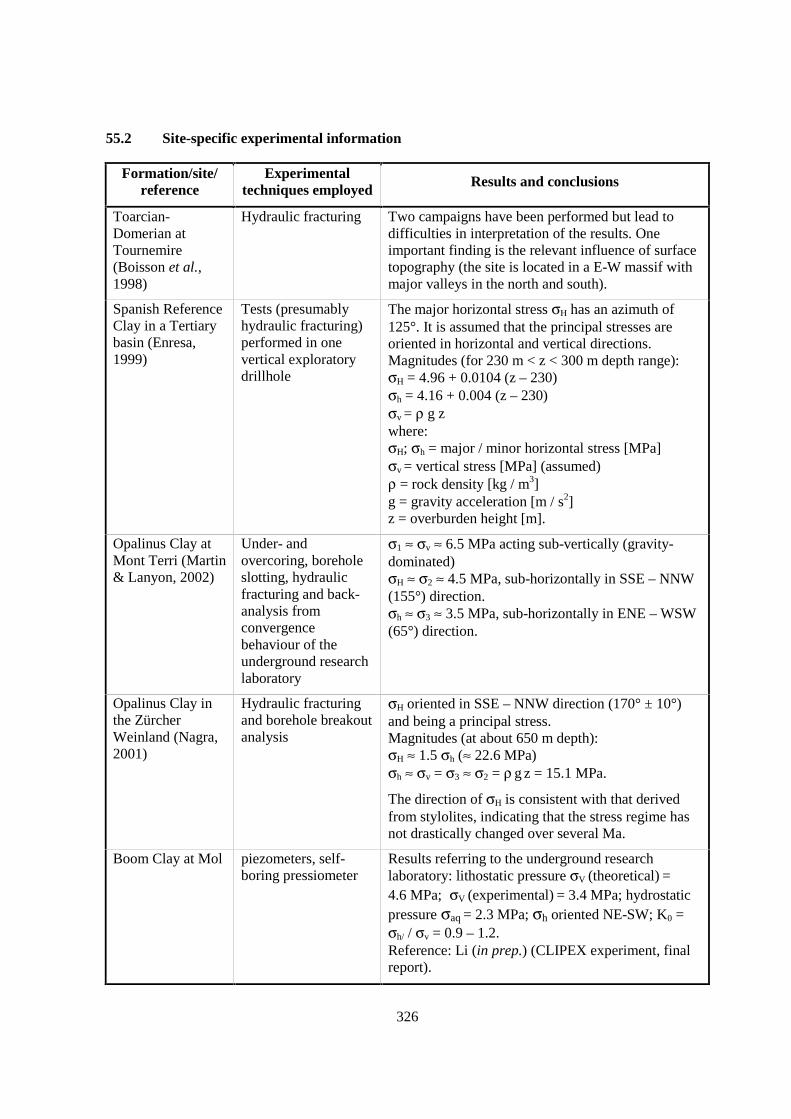
326
55.2 Site-specific experimental information
Formation/site/reference
Experimentaltechniques employed Results and conclusions
Toarcian-Domerian atTournemire(Boisson et al.,1998)
Hydraulic fracturing Two campaigns have been performed but lead todifficulties in interpretation of the results. Oneimportant finding is the relevant influence of surfacetopography (the site is located in a E-W massif withmajor valleys in the north and south).
Spanish ReferenceClay in a Tertiarybasin (Enresa,1999)
Tests (presumablyhydraulic fracturing)performed in onevertical exploratorydrillhole
The major horizontal stress σH has an azimuth of125°. It is assumed that the principal stresses areoriented in horizontal and vertical directions.Magnitudes (for 230 m < z < 300 m depth range):σH = 4.96 + 0.0104 (z – 230)σh = 4.16 + 0.004 (z – 230)σv = ρ g zwhere:σH; σh = major / minor horizontal stress [MPa]σv = vertical stress [MPa] (assumed)ρ = rock density [kg / m3]g = gravity acceleration [m / s2]z = overburden height [m].
Opalinus Clay atMont Terri (Martin& Lanyon, 2002)
Under- andovercoring, boreholeslotting, hydraulicfracturing and back-analysis fromconvergencebehaviour of theunderground researchlaboratory
σ1 ≈ σv ≈ 6.5 MPa acting sub-vertically (gravity-dominated)σH ≈ σ2 ≈ 4.5 MPa, sub-horizontally in SSE – NNW(155°) direction.σh ≈ σ3 ≈ 3.5 MPa, sub-horizontally in ENE – WSW(65°) direction.
Opalinus Clay inthe ZürcherWeinland (Nagra,2001)
Hydraulic fracturingand borehole breakoutanalysis
σH oriented in SSE – NNW direction (170° ± 10°)and being a principal stress.Magnitudes (at about 650 m depth):σH ≈ 1.5 σh (≈ 22.6 MPa)σh ≈ σv = σ3 ≈ σ2 = ρ g z = 15.1 MPa.
The direction of σH is consistent with that derivedfrom stylolites, indicating that the stress regime hasnot drastically changed over several Ma.
Boom Clay at Mol piezometers, self-boring pressiometer
Results referring to the underground researchlaboratory: lithostatic pressure σV (theoretical) =4.6 MPa; σV (experimental) = 3.4 MPa; hydrostaticpressure σaq = 2.3 MPa; σh oriented NE-SW; K0 =σh/ / σv = 0.9 – 1.2.Reference: Li (in prep.) (CLIPEX experiment, finalreport).
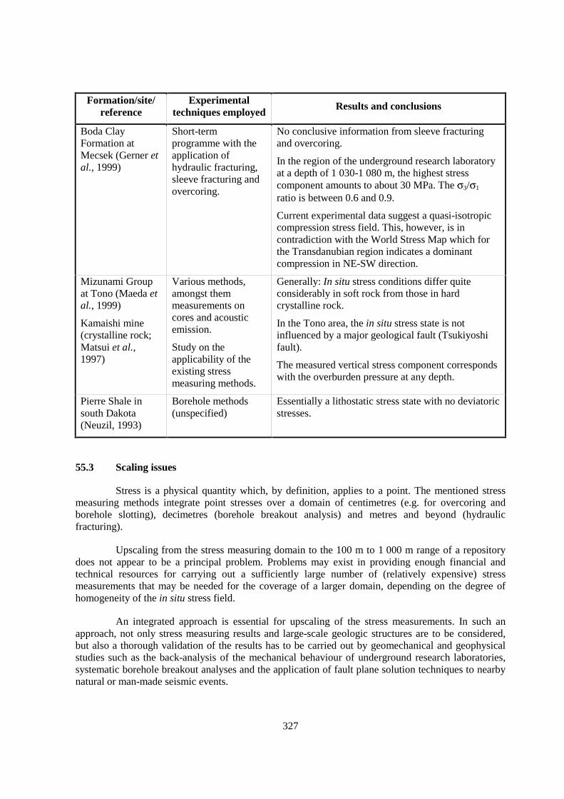
327
Formation/site/reference
Experimentaltechniques employed
Results and conclusions
Boda ClayFormation atMecsek (Gerner etal., 1999)
Short-termprogramme with theapplication ofhydraulic fracturing,sleeve fracturing andovercoring.
No conclusive information from sleeve fracturingand overcoring.
In the region of the underground research laboratoryat a depth of 1 030-1 080 m, the highest stresscomponent amounts to about 30 MPa. The σ3/σ1
ratio is between 0.6 and 0.9.
Current experimental data suggest a quasi-isotropiccompression stress field. This, however, is incontradiction with the World Stress Map which forthe Transdanubian region indicates a dominantcompression in NE-SW direction.
Mizunami Groupat Tono (Maeda etal., 1999)
Kamaishi mine(crystalline rock;Matsui et al.,1997)
Various methods,amongst themmeasurements oncores and acousticemission.
Study on theapplicability of theexisting stressmeasuring methods.
Generally: In situ stress conditions differ quiteconsiderably in soft rock from those in hardcrystalline rock.
In the Tono area, the in situ stress state is notinfluenced by a major geological fault (Tsukiyoshifault).
The measured vertical stress component correspondswith the overburden pressure at any depth.
Pierre Shale insouth Dakota(Neuzil, 1993)
Borehole methods(unspecified)
Essentially a lithostatic stress state with no deviatoricstresses.
55.3 Scaling issues
Stress is a physical quantity which, by definition, applies to a point. The mentioned stressmeasuring methods integrate point stresses over a domain of centimetres (e.g. for overcoring andborehole slotting), decimetres (borehole breakout analysis) and metres and beyond (hydraulicfracturing).
Upscaling from the stress measuring domain to the 100 m to 1 000 m range of a repositorydoes not appear to be a principal problem. Problems may exist in providing enough financial andtechnical resources for carrying out a sufficiently large number of (relatively expensive) stressmeasurements that may be needed for the coverage of a larger domain, depending on the degree ofhomogeneity of the in situ stress field.
An integrated approach is essential for upscaling of the stress measurements. In such anapproach, not only stress measuring results and large-scale geologic structures are to be considered,but also a thorough validation of the results has to be carried out by geomechanical and geophysicalstudies such as the back-analysis of the mechanical behaviour of underground research laboratories,systematic borehole breakout analyses and the application of fault plane solution techniques to nearbynatural or man-made seismic events.
328
55.4 Scientific level of understanding
The global and regional present-day stress regimes are generally reasonably well understoodas, for example, is evidenced in the World Stress Map. However, in the absence of site-specific stressmeasurements, the general level of understanding is insufficient with regard to the stress regimesacting at the local scale, including that of the usual scale of a repository system. The global stress statecan be quite substantially superimposed by local factors, to a degree that the local stress state mayhave no resemblance with the global or regional states. Factors which are responsible for such stressvariations are irregular morphology, residual stresses, stress inhomogeneities due to lithologic changes(different strata) and geological faults.
A number of methods and tools are available for site-specific measurements of the stressfield. A major problem is the fact that in over-consolidated argillaceous formations, many of thestandard stress measuring methods do not work properly either technically and/or from a conceptualpoint of view. In such formations, the borehole walls tend to be unstable. Thus it is often difficult, ifnot impossible, to provide regular, cylindrical boreholes which are required in most stress measuringtests (e.g. hydro fracturing, overcoring). Linearly behaving borehole wall rocks are also an intrinsicrequirement for the applicability of most standard stress measuring methods such as overcoring andborehole slotting. Moreover, disturbances and fracturing of the borehole wall material are common.Another problem which is notorious in argillaceous materials is the effect of material and rock massanisotropy onto the state of the in situ stresses as well as onto the stress measuring results.
Careful drilling in combination with purpose-designed, -executed and -evaluated tests arerequired to alleviate these problems. The use of independent methods in parallel adds confidence tothe experimental results.
55.5 Linked FEPs
FEP 5 Hydraulic potentials and gradients in the host rock, including boundary conditions
FEP 14 Lithology, mineralogy of rocks and fracture infills
FEP 37 Geomechanical rock properties
FEP 50 Past burial history
55.6 Level of understanding from a PA perspective and treatment in PA
Knowledge of the present-day in situ stress regime of the host-rock formation is a primerequirement for repository design and construction. Conceptually and technically, it is feasible to gainsuch knowledge, provided that the geological structure is not too complex, sufficient funding isavailable for a reasonably large number of in situ stress measurements and an integrated approach ischosen in the evaluation of stress data. In most sites considered it is felt that such knowledge is not yetavailable to the degree needed. The Zürcher Weinland in NE Switzerland is an exception: The regionalin situ stresses have been determined to a level of accuracy which is believed to be sufficient for theactual stage of the project development.
Within a siting study, the present-day in situ stress regime is an essential element of thegeological boundary conditions, and its explicit specification is required. The geologic state of stresshas implications in both the far and the affected field of a repository. In the far field, the geologicstresses have to be considered in the design of the layout of underground works such as the
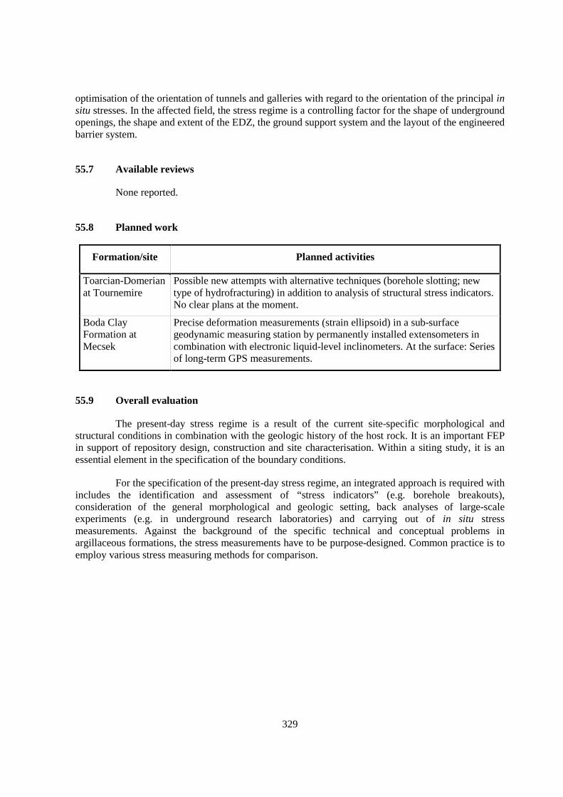
329
optimisation of the orientation of tunnels and galleries with regard to the orientation of the principal insitu stresses. In the affected field, the stress regime is a controlling factor for the shape of undergroundopenings, the shape and extent of the EDZ, the ground support system and the layout of the engineeredbarrier system.
55.7 Available reviews
None reported.
55.8 Planned work
Formation/site Planned activities
Toarcian-Domerianat Tournemire
Possible new attempts with alternative techniques (borehole slotting; newtype of hydrofracturing) in addition to analysis of structural stress indicators.No clear plans at the moment.
Boda ClayFormation atMecsek
Precise deformation measurements (strain ellipsoid) in a sub-surfacegeodynamic measuring station by permanently installed extensometers incombination with electronic liquid-level inclinometers. At the surface: Seriesof long-term GPS measurements.
55.9 Overall evaluation
The present-day stress regime is a result of the current site-specific morphological andstructural conditions in combination with the geologic history of the host rock. It is an important FEPin support of repository design, construction and site characterisation. Within a siting study, it is anessential element in the specification of the boundary conditions.
For the specification of the present-day stress regime, an integrated approach is required withincludes the identification and assessment of “stress indicators” (e.g. borehole breakouts),consideration of the general morphological and geologic setting, back analyses of large-scaleexperiments (e.g. in underground research laboratories) and carrying out of in situ stressmeasurements. Against the background of the specific technical and conceptual problems inargillaceous formations, the stress measurements have to be purpose-designed. Common practice is toemploy various stress measuring methods for comparison.

331
56. FUTURE STRESS REGIME (FEP C2.6)
56.1 Definition and generalities
This FEP relates to the future geological and geomorphological setting of the host rock overPA-relevant geological times. It is intrinsically related to the geodynamic development of the hostrock formation in connection with pertinent geological processes such as uplift, erosion, subsidence,sedimentation and tectonic stress regimes.
56.2 Site-specific experimental information
The direction of present-day σH in Opalinus Clay in the Benken borehole is consistent withthe one derived from stylolites, indicating that the stress regime has not drastically changed over thepast several Ma. This is taken as evidence that the regional tectonic stress field will remain constant atleast over the coming 1 Ma. However, due to the effects of ongoing uplift (0.1 mm/a), σv willdecrease. Within 1 Ma, maximum erosion is 200 m, reducing the overburden of the repository from650 to 450 m. The related decrease of the horizontal stress components depends on the model/conceptchosen (Nagra, 2002).
56.3 Scaling issues
None reported.
56.4 Scientific level of understanding
Over the time scales considered here, major changes of horizontal stresses due to a changinggeodynamic situation are not likely. However, vertical movements may be relevant.
Regional uplift in combination with erosion will lead to a decrease of the magnitudes of therelevant stress components σH, σh and σv of the host rock (for definition of σH, σh and σv see FEP 55).The magnitudes of the decrease of these stress components will be unequal. The stress release will begreatest in the vertical direction and smallest in horizontal directions (due to the continuousconfinement). This has the consequence that the proportion between horizontal and vertical stressesσH/σv will be increased. The orientations of the principal stresses tend to reverse in the sense that, forinstance, a vertically oriented σ1 is turned into a horizontal direction and vice versa for σ2 and/or σ3
(Bock 1975). With continued uplift and erosion, the growing stress anisotropy may be released byinelastic processes (e.g. by the formation of surface-parallel extension fractures). Based on fieldevidence from several argillaceous formations, this typically happens in the uppermost decametresbelow surface.
332
In the case of subsidence in combination with sedimentation, the higher overburden pressurewill lead towards higher values of the total stresses, whilst the ratio the horizontal to the vertical stresscomponents will tend towards unity (σH/σv � 1; isotropic stress state). This would generally meanmore favourable boundary stress conditions for the repository. If the subsidence rate is high and thehydraulic conductivity of the host rock is comparatively low (the latter condition tends to prevail inargillaceous formations), significant pore-water excess pressures may develop, particularly if theoverburden pressure σv exceeds the pre-consolidation pressure (i.e. the maximal pressure of thegeological past). This, in turn, leads to the situation that the effective stresses are not increased to thedegree as is the case for the total stresses (see FEP 58).
56.5 Linked FEPs
FEP 14 Lithology, mineralogy of rocks and fracture infills
FEP 37 Geomechanical rock properties
FEP 50 Past burial history
FEP 55 Present-day stress regime
FEP 57 Geomechanical effects of erosion / unloading
FEP 58 Consolidation due to burial
FEP 59 Future evolution of hydraulic potentials and gradients (e.g. due to erosion or burial)
56.6 Level of understanding from a PA perspective and treatment in PA
Knowledge of the future in situ stress regime is required as an explicit boundary condition ifthe long-term evolution is modelled within the domain of the repository. The future in situ stressregime is intrinsically related to the geodynamic and morphological development of the host-rockformation (uplift, erosion, subsidence, sedimentation, tectonic stress; see FEPs 57-59).
It is generally recognised that the regional tectonic stress regime at any of the sitesconsidered will not change substantially over PA-relevant time scales. However, the stress field atrepository level may change in response to possible changes of lithostatic pressure due to erosion orsedimentation (see also FEP 57). In spite of the uncertainties related to the evolution of horizontalstresses in response to a changed vertical stress, knowledge is regarded as sufficient for PA purposes.
56.7 Available reviews
None reported.
56.8 Planned work
None reported.
56.9 Overall evaluation
The regional tectonic stress regime is not expected to change substantially over PA-relevanttime scales. However, the stress field at repository level may change in response to possible changesof lithostatic pressure due to erosion or sedimentation. In specific, the possibility of inelasticdeformation due to erosion merits consideration in PA.
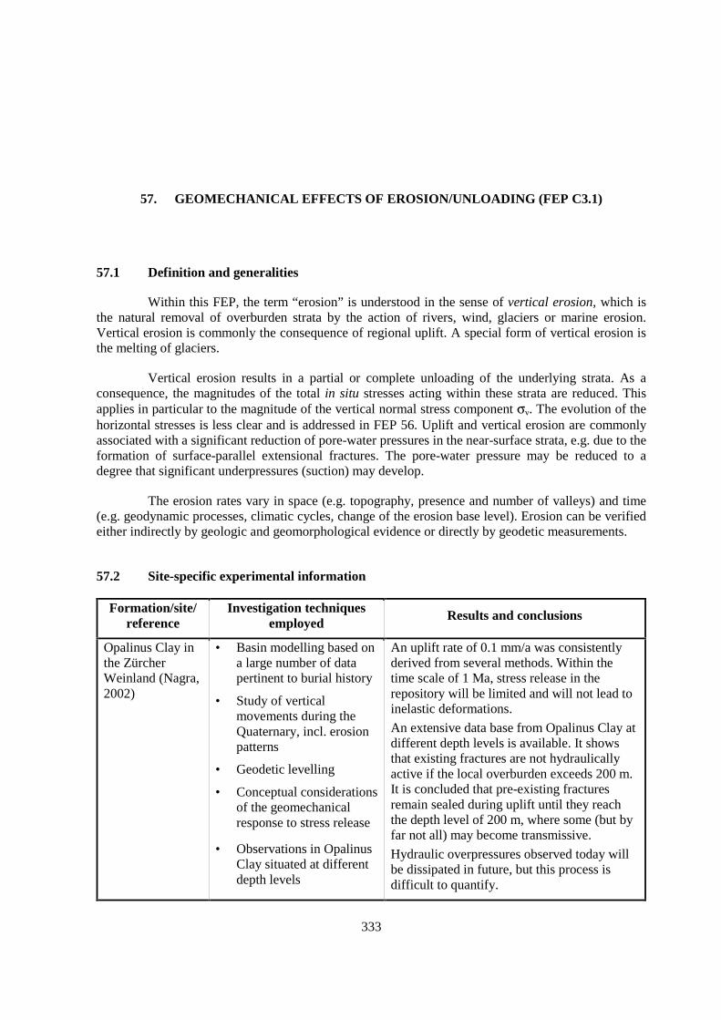
333
57. GEOMECHANICAL EFFECTS OF EROSION/UNLOADING (FEP C3.1)
57.1 Definition and generalities
Within this FEP, the term “erosion” is understood in the sense of vertical erosion, which isthe natural removal of overburden strata by the action of rivers, wind, glaciers or marine erosion.Vertical erosion is commonly the consequence of regional uplift. A special form of vertical erosion isthe melting of glaciers.
Vertical erosion results in a partial or complete unloading of the underlying strata. As aconsequence, the magnitudes of the total in situ stresses acting within these strata are reduced. Thisapplies in particular to the magnitude of the vertical normal stress component σv. The evolution of thehorizontal stresses is less clear and is addressed in FEP 56. Uplift and vertical erosion are commonlyassociated with a significant reduction of pore-water pressures in the near-surface strata, e.g. due to theformation of surface-parallel extensional fractures. The pore-water pressure may be reduced to adegree that significant underpressures (suction) may develop.
The erosion rates vary in space (e.g. topography, presence and number of valleys) and time(e.g. geodynamic processes, climatic cycles, change of the erosion base level). Erosion can be verifiedeither indirectly by geologic and geomorphological evidence or directly by geodetic measurements.
57.2 Site-specific experimental information
Formation/site/reference
Investigation techniquesemployed
Results and conclusions
Opalinus Clay inthe ZürcherWeinland (Nagra,2002)
• Basin modelling based ona large number of datapertinent to burial history
• Study of verticalmovements during theQuaternary, incl. erosionpatterns
• Geodetic levelling
• Conceptual considerationsof the geomechanicalresponse to stress release
• Observations in OpalinusClay situated at differentdepth levels
An uplift rate of 0.1 mm/a was consistentlyderived from several methods. Within thetime scale of 1 Ma, stress release in therepository will be limited and will not lead toinelastic deformations.
An extensive data base from Opalinus Clay atdifferent depth levels is available. It showsthat existing fractures are not hydraulicallyactive if the local overburden exceeds 200 m.It is concluded that pre-existing fracturesremain sealed during uplift until they reachthe depth level of 200 m, where some (but byfar not all) may become transmissive.
Hydraulic overpressures observed today willbe dissipated in future, but this process isdifficult to quantify.
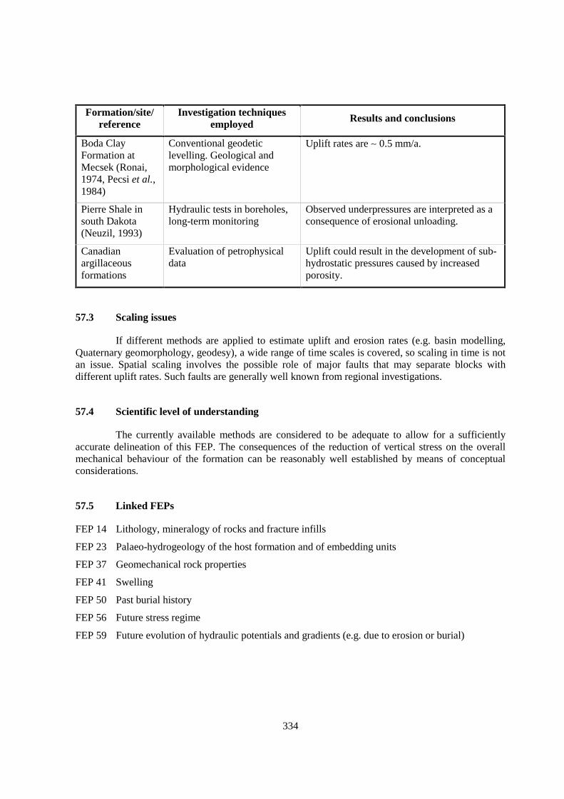
334
Formation/site/reference
Investigation techniquesemployed Results and conclusions
Boda ClayFormation atMecsek (Ronai,1974, Pecsi et al.,1984)
Conventional geodeticlevelling. Geological andmorphological evidence
Uplift rates are ∼ 0.5 mm/a.
Pierre Shale insouth Dakota(Neuzil, 1993)
Hydraulic tests in boreholes,long-term monitoring
Observed underpressures are interpreted as aconsequence of erosional unloading.
Canadianargillaceousformations
Evaluation of petrophysicaldata
Uplift could result in the development of sub-hydrostatic pressures caused by increasedporosity.
57.3 Scaling issues
If different methods are applied to estimate uplift and erosion rates (e.g. basin modelling,Quaternary geomorphology, geodesy), a wide range of time scales is covered, so scaling in time is notan issue. Spatial scaling involves the possible role of major faults that may separate blocks withdifferent uplift rates. Such faults are generally well known from regional investigations.
57.4 Scientific level of understanding
The currently available methods are considered to be adequate to allow for a sufficientlyaccurate delineation of this FEP. The consequences of the reduction of vertical stress on the overallmechanical behaviour of the formation can be reasonably well established by means of conceptualconsiderations.
57.5 Linked FEPs
FEP 14 Lithology, mineralogy of rocks and fracture infills
FEP 23 Palaeo-hydrogeology of the host formation and of embedding units
FEP 37 Geomechanical rock properties
FEP 41 Swelling
FEP 50 Past burial history
FEP 56 Future stress regime
FEP 59 Future evolution of hydraulic potentials and gradients (e.g. due to erosion or burial)
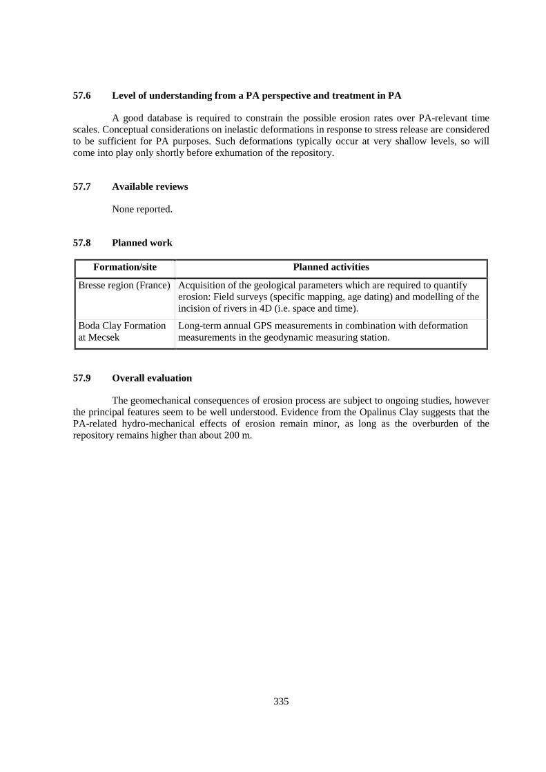
335
57.6 Level of understanding from a PA perspective and treatment in PA
A good database is required to constrain the possible erosion rates over PA-relevant timescales. Conceptual considerations on inelastic deformations in response to stress release are consideredto be sufficient for PA purposes. Such deformations typically occur at very shallow levels, so willcome into play only shortly before exhumation of the repository.
57.7 Available reviews
None reported.
57.8 Planned work
Formation/site Planned activities
Bresse region (France) Acquisition of the geological parameters which are required to quantifyerosion: Field surveys (specific mapping, age dating) and modelling of theincision of rivers in 4D (i.e. space and time).
Boda Clay Formationat Mecsek
Long-term annual GPS measurements in combination with deformationmeasurements in the geodynamic measuring station.
57.9 Overall evaluation
The geomechanical consequences of erosion process are subject to ongoing studies, howeverthe principal features seem to be well understood. Evidence from the Opalinus Clay suggests that thePA-related hydro-mechanical effects of erosion remain minor, as long as the overburden of therepository remains higher than about 200 m.

337
58. CONSOLIDATION DUE TO BURIAL (FEP C3.2)
58.1 Definition and generalities
The title of this FEP can be understood in different ways.
In a general sense, consolidation is a time-dependent transfer of a water-saturated cohesivesoil or silty-argillaceous rock into a higher-density state (reduction of porosity) due to increasedoverburden pressure. The transfer is controlled by the rate at which the excess pore-water pressure isdissipated (expulsion of pore-water). The dissipation process is a function of the hydraulicconductivity of the soil or rock, the drainage conditions and the loading rate.
In a narrow sense, consolidation is understood as a compaction process of the EDZ due toswelling of the host rock or of the backfill. A major part of this process will take place in unsaturatedconditions. The term “consolidation” therefore seems to be less appropriate and may be substituted bythe term “compaction”, “re-compaction”, “homogenisation” or similar.
Within the context of this FEP, consolidation is understood in the general sense. It is aprocess that may become effective when the repository host rock will be subject to subsidence incombination with sedimentation. Considering the fundamental geomechanical stress equation asformulated by Terzaghi (1925)
σtot = σ’ + p
with: σtot = total stressσ’ = effective stressp = pore-water pressure,
three scenarios are principally possible with regard to the pore-water pressure development when arock formation is subjected to an additional overburden pressure due to burial:
1. Saturated conditions and high hydraulic conductivity: The pore-water pressure remainshydrostatic (equivalent to the hydraulic head).
2. Saturated conditions and low hydraulic conductivity: Excess pore-water pressure develops(pore-water cannot be expelled at the rate at which the overburden pressure is increased).
3. Underpressured conditions and low hydraulic conductivity: In the case of basin inversion, aburied formation will be uplifted and decompacted, leading to over-consolidation and to thedevelopment of underpressures. In certain cases, this could also lead to the exsolution of gasand thus to unsaturated conditions. Re-loading by increased overburden yields apredominantly elastic response of the rock as long as the maximum overburden pressure ofthe geological past is not exceeded. No excess pore-water pressure will develop, and therewill be no consolidation process at all.
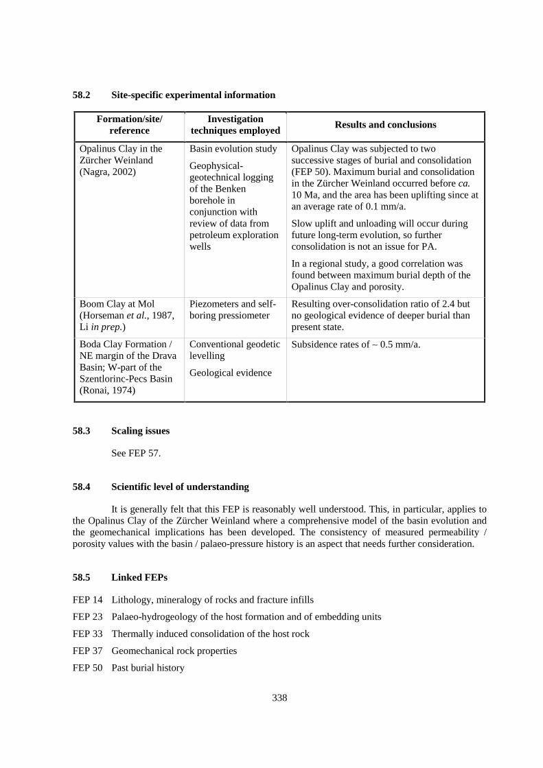
338
58.2 Site-specific experimental information
Formation/site/reference
Investigationtechniques employed Results and conclusions
Opalinus Clay in theZürcher Weinland(Nagra, 2002)
Basin evolution study
Geophysical-geotechnical loggingof the Benkenborehole inconjunction withreview of data frompetroleum explorationwells
Opalinus Clay was subjected to twosuccessive stages of burial and consolidation(FEP 50). Maximum burial and consolidationin the Zürcher Weinland occurred before ca.10 Ma, and the area has been uplifting since atan average rate of 0.1 mm/a.
Slow uplift and unloading will occur duringfuture long-term evolution, so furtherconsolidation is not an issue for PA.
In a regional study, a good correlation wasfound between maximum burial depth of theOpalinus Clay and porosity.
Boom Clay at Mol(Horseman et al., 1987,Li in prep.)
Piezometers and self-boring pressiometer
Resulting over-consolidation ratio of 2.4 butno geological evidence of deeper burial thanpresent state.
Boda Clay Formation /NE margin of the DravaBasin; W-part of theSzentlorinc-Pecs Basin(Ronai, 1974)
Conventional geodeticlevelling
Geological evidence
Subsidence rates of ∼ 0.5 mm/a.
58.3 Scaling issues
See FEP 57.
58.4 Scientific level of understanding
It is generally felt that this FEP is reasonably well understood. This, in particular, applies tothe Opalinus Clay of the Zürcher Weinland where a comprehensive model of the basin evolution andthe geomechanical implications has been developed. The consistency of measured permeability /porosity values with the basin / palaeo-pressure history is an aspect that needs further consideration.
58.5 Linked FEPs
FEP 14 Lithology, mineralogy of rocks and fracture infills
FEP 23 Palaeo-hydrogeology of the host formation and of embedding units
FEP 33 Thermally induced consolidation of the host rock
FEP 37 Geomechanical rock properties
FEP 50 Past burial history

339
FEP 51 Present and future geothermal regime and related processes
FEP 56 Future stress regime
FEP 59 Future evolution of hydraulic potentials and gradients (e.g. due to erosion or burial)
58.6 Level of understanding from a PA perspective and treatment in PA
Consolidation may have the following consequences that are relevant to PA:
1. Anomalous pressures (overpressures) may be generated (see FEP 59).
2. The hydrogeological properties of the argillaceous host rock may change (in particular thepermeability, the porosity and the diffusivity).
3. The geomechanical properties may change (strength and plasticity).
In principle, the PA results are sensitive to all these aspects. However, none of the sitesconsidered is being buried at rates sufficient to result in PA-relevant consequences over time scales inthe order of 1 Ma. Therefore, while conceptual understanding is regarded as sufficient, no relevance isattributed to this FEP in PA studies.
58.7 Available reviews
None reported.
58.8 Planned work
Drava and Szentlorinc-Pecs basins (Hungary): Long-term annual GPS measurements incombination with deformation measurements in the geodynamic measuring station.
58.9 Overall evaluation
The geological and geomechanical features of the consolidation process are well understood.To increase the level of the confidence in the common hydrogeological and geomechanical modelsand data bases over PA time scales, a better understanding is desirable of how further consolidationwould affect the hydrogeological and geomechanical properties of the host rock formation.

341
59. FUTURE EVOLUTION OF HYDRAULIC POTENTIALS AND GRADIENTS(E.G. DUE TO EROSION OR BURIAL) (FEP C3.3)
59.1 Definition and generalities
Geological processes such as sedimentation, erosion or glacial stages affect hydraulicpotentials and gradients in a deep argillaceous formation. First, such processes may lead to majorchanges in the hydraulic conditions in the embedding, more highly permeable rock units. Because ofthe low hydraulic conductivity of argillaceous formations, the time required to equilibrate theirhydraulic potentials can be very long (many thousands to millions of years). Second, a change inoverburden may result in volumetric deformation within the argillaceous formation. Increasing theload can lead to further consolidation (FEP 58), while unloading can lead to an elastic rebound,swelling or even fracturing (FEP 57). By consequence, currently measured potentials may representnon-equilibrium conditions (see FEP 5).
59.2 Site-specific experimental information
Non-equilibrium (abnormal) hydraulic potentials have been measured in several argillaceousformations (see FEP 5). However, observation times are much too short compared to the longequilibration times of natural hydraulic disequilibria, so the rates of equilibration are difficult toconstrain.
At several sites, geodetic measurements are performed to determine current rates of uplift orsubsidence. Such measurements, together with data based on the long-term burial history (FEP 50),are used to predict future vertical movements and the evolution of topography. These factors alsodetermine the future evolution of potentials in the aquifers and in the argillaceous formation itself.
59.3 Scaling issues
Because the geological, hydrogeological and geomechanical processes governing the futureevolution of hydraulic potentials are very slow, the temporal extrapolation of current observations isparticularly difficult. For the extrapolation of the occurrence of future glaciations, the Milankovitchastronomical theory is well established (Loutre & Berger, 2000) but could be affected by a strongimpact of anthropogenic CO2 release to the atmosphere.
59.4 Scientific level of understanding
The basic phenomena are well understood, and the hydro-mechanical models to explainover- or underpressures due to changes in hydraulic boundary conditions or load on an argillaceousformation are available. Similarly, the potential effects of glaciations (ice loading, permafrost) onhydraulic potentials and gradients are rather well understood. Palaeo-hydrogeological studies in

342
combination with the Milankovitch astronomical theory have been used to predict future evolution ofhydraulic potentials in sedimentary basins (e.g. Marivoet et al., 2000). However, the site-specificunderstanding of the future evolution of geological processes such as uplift and subsidence, oftenremains poor.
59.5 Linked FEPs
FEP 5 Hydraulic potentials and gradients in the host rock, including boundary conditions
FEP 6 Hydraulic properties of the host rock
FEP 7 Units over- and underlying the host formation: local and regional hydrogeologic framework
FEP 23 Palaeo-hydrogeology of the host formation and of embedding units
FEP 24 Evolution of pore-fluid (water and gas) chemistry and mineralogy in the host formation andin embedding units
FEP 25 Water residence times in the host formation
FEP 50 Past burial history
FEP 54 Future fault (re)activation, changes in migration pathways; changes of hydraulic parameters;flow events
FEP 56 Future stress regime
FEP 58 Consolidation due to burial
FEP 59 Future evolution of hydraulic potentials and gradients (e.g. due to erosion or burial)
59.6 Level of understanding from a PA perspective and treatment in PA
Decreasing or increasing of the load on an argillaceous formation will lead to thedevelopment of over- or underpressures, and this can lead to a water flux out of the formation or intothe formation. In case of underpressure in the host formation, the incoming water flux might hinder thetransport of radionuclides out of the repository, while in case of overpressure it might lead to anenhanced outward radionuclide transport because the hydraulic gradient points out of the formation onboth sides.
In diffusion-dominated formations, even an increase of the outward advective flux due to therelaxation of overpressure is likely to be of low relevance because the expected changes in gradientsand resulting advective fluxes are generally not drastic enough to result in advection as the dominanttransport process. On the other hand, in advection-dominated systems, advective flux will increaselinearly to the increase of the hydraulic gradient and thus may lead to enhanced radionuclide transport.
Overpressures observed today in the Opalinus Clay of the Zürcher Weinland may at leastpartially be due to consolidation during maximum burial of the formation 10 Ma ago. Given theundisputedly long time scales related to the dissipation of the overpressures in this diffusion-dominated formation, these are unlikely to drive significant advective transport. Thus, they areneglected in the PA formulation of transport models for the geosphere. Better understanding of theunderlying processes for the generation of overpressures would add further confidence.
343
The influence of the changes in hydraulic potentials induced by glaciations (changing loads,permafrost) on radionuclide transport have been explicitly treated in performance assessment studiesfor the Mol site and the Paris basin (Certes et al., 1997). The effects of glacial loads on pore-waterpressures in Opalinus Clay were also quantified, and the related fluxes are negligible according tomodel calculations (Nagra, 2002).
59.7 Available reviews
None reported.
59.8 Planned work
None reported.
59.9 Overall evaluation
This FEP is of importance for understanding the potential evolution of the wholehydrogeological system. At the considered sites, no important effects on the outcome of PA studies areexpected, even though, it may have some importance in advection dominated systems. Current burialrates are typically too slow to result in significant consolidation and a major pore-pressure increaseover a time scale of 1 Ma. Thus, for the considered formations, overpressures may be neglected in theformulation of transport models for the geosphere. The only exception is the possible influence ofglaciations (changing loads, permafrost) in some but not all cases.

345
SECTION III
References
The numbers behind each reference refer to the FEP numberin Section II where this reference is quoted.
S.I = quoted from Section I.

347
Adler, M. (2001): Interaction of clay stone and hyperalkaline solutions at 30ºC: acombined experimental and modeling study. PhD thesis, Univ. Bern,Switzerland.
29
Adler, M., Mäder, U.K. & Waber, H.N. (1999): High-pH alteration of argillaceousrocks: an experimental study. Swiss Bulletin of Mineralogy and Petrology79, 445-454.
29
Adler, M., Mäder, U.K. & Waber, H.N. (2001): Core infiltration experimentinvestigating high-pH alteration of low-permeability argillaceous rock at30ºC. In: Cidu, R. (ed.): Proceedings 10th International Symposium onWater/Rock Interaction, WRI-10, Villasimius, Italy, 10-15 July 2001,1299-1302. Balkema, Rotterdam.
29, 42
Aertsens, M., Put, M. & Dierckx, A. (2003): An analytical model for theinterpretation of pulse injection experiments performed for testing thespatial variability of clay formations. Journal of Contaminant Hydrology61, 423-436.
S.I
AGEM (1998): Référentiel géomecanique, Site de l’Est. Andra report D RP AGEM98-050/A, France.
32, 34, 37
AGEM (1999): Modèles rhéologiques des argillites de l’Est – Bilan d’étape desétudes rhéologiques, site Est. Andra report C RP AGEM 99-061, France.
37
Ahorner, L. (1992): Das Erdbeben bei Roermond am 13. April 1992 und die darauszu ziehenden Lehren für das Erdbebengefährdungspotential im Rheinland.Mitteilungen der Deutschen Geophysikalischen Gesellschaft, Nr. 1-2/1992.
54
Alexander, W.R. (ed.) (1995a): A natural analogue of cement-buffered,hyperalkaline groundwaters and their interaction with a sedimentary hostrock, Phase I: definition of source terms. Nagra Technical Report NTB 91-10, Switzerland.
29
Alexander, W.R. (1995b): Natural cements: How can they help us safely dispose ofradioactive waste ? Radwaste Magazine 2, 61-69.
29
Alheid, H.J., Knecht, M., Boisson, J.-Y., Homand F. & Pepa, S. (1999): Comparisonof in-situ hydraulic and seismic measurements in the excavation damagedzone of underground drifts. In: Vouille & Berest (eds): Proceedings of the9th International Congress on Rock Mechanics, Paris, France, 1263-1266.Balkema, Rotterdam.
35, 38
Allison, J.D., Brown, D.S., and Novo-Gradac, K.J. (1991): MINTEQA2/PRODEFA2, a geochemical assessment model for environmental systems:version 3.0 user’s manual. Athens, GA, U. S. Environmental ProtectionAgency Report EPA/600/3-91/021, 107 p.
22
Altmann, S. & Bruno, J. (2001): Using thermodynamic sorption models for guidingradioelement distribution coefficient (Kd) investigations: A status report.OECD/NEA, Paris.
S.I, 20, 21
Andra (1998): Comportement différé compte-tenu des couplages thermo-hydromécanique des argilites silto-carbonatées de l’Est. Andra report B RPG3S (98-007), France.
41
Andra (1999a): Référentiel géologique du Site de l’Est. Andra report A RP ADS 99-005, France.
S.I, 2, 3, 5, 6, 7,8, 17, 20, 43
Andra (1999b): Couplages hydro-mécaniques dans les argilites de l’Est et les siltitesdu Gard. Andra report B RP G3S (99-003), France.
41
348
Andra (1999c): Étude du Gard Rhodanien. Actes des Journées ScientifiquesCNRS/Andra, Bagnols-sur-Cèze, 20-21 octobre 1997. EDP Sciences, LesUlis, France, 223 p.
S.I
Aplin, C.A., Fleet, A.J. & Macquaker, J.H.S. (1999): Muds and mudstones: physicaland fluid-flow properties. Geological Society of London SpecialPublication 158, London.
S.I
Arkai, P., Balogh, K., Demeny, A., Forizs, I., Nagy, G. & Mathe, Z. (2000):Composition, diagenetic and post-diagenetic alterations of a possibleradioactive waste repository site: the Boda Albitic Claystone Formation,southern Hungary. Acta Geologica Hungarica 43, 351-378.
13
Atkins, P.W. (1990): Physical chemistry. 4th ed., Oxford Univ. Press. 8Babot, Y. (1999): Hydrogéologie des formations carbonatées jurassiques dand l’Est
du bassin de Paris. In: Étude de l’Est du Bassin Parisien, Actes desJournées Scientifiques CNRS/ANDRA, Bar le Duc, 20-21 octobre 1997,65-76.
2
Baeyens, B., Maes, A., Cremers, A. & Henrion, P.N. (1985): In situ physico-chemical characterization of Boom Clay. Radioactive Waste Managementand the Nuclear Fuel Cycle 6, 391-408.
16, 20
Baeyens, B. & Bradbury, M.H. (1994): Physico-Chemical Characterisation andCalculated In Situ Porewater Chemistries for a Low Permeability PalfrisMarl Sample from Wellenberg. Nagra Technical Report NTB 94-22,Switzerland.
9, 20
Baeyens, B. & Bradbury, M.H. (1997): A mechanistic description of Ni and Znsorption on Na-montmorillonite, Part I: Titration and sorptionmeasurements. Journal of Contaminant Hydrology 27, 199-222.
21
Barbreau, A. & Boisson, J.-Y. (1994): Caractérisation d’une formation argileuse.Synthèse des principaux résultats obtenus à partir du tunnel de Tournemirede janvier 1992 à juin 1993. EC Rapp. d’activité 1991-93. CEC NuclearScience & Technology Series, Luxembourg, EUR 15756 FR.
2, 37
Barnichon, J.D. & Bernier, F. (1999): Observed fracturing around the excavationworks in Boom Clay at Mol, Belgium. Abstract of the 2nd Euroconferenceon Rock Physics and Mechanics, Edinburgh, Scotland, 14-18 November1999.
35
Barnichon, J.D. & Volckaert, G. (2003): Observation and predictions ofhydromechanical coupling effects in the Boom clay, Mol UndergroundResearch Laboratory, Belgium. Hydrogeological Journal 11, 193-202.
35
Baston, G.M.N., Berry, J.A. & Bond, K.A., Brownsword, M. & Linklater, C.M.(1991): Studies of the effects of organic materials on the sorption ofuranium (IV) and thorium (IV) on London Clay and Caithness Flagstones.Nirex Report NSS/R258, UK.
30
Baston, G.M.N., Berry, J.A. & Bond, K.A. (2001): Effects of near-field perturbationson uranium (VI) and radium diffusion through London Clay and the UpperCaithness Flagstone Group. Nirex Report NSS/R351, UK.
30
Bateman, K., Coombs, P., Noy, D.J., Pearce, J.M. & Wetton, P.D. (1997): Numericalmodelling and column experiments to simulate the alkaline disturbed zonearound a cementitious nuclear waste repository. Materials ResearchSociety Symposium Proceedings 506, 605-611.
29
349
Bateman, K., Coombs, P., Pearce, J.M., Noy, D.J., Rochelle, C.A., and Wetton, P.D.(2000): Column experiments, Phase II. Nagra Internal Report, Switzerland.
29
Bath, A.H. (2001): Pore-waters in mesozoic mudrocks in southern England. In: Cidu,R. (ed.): Proceedings 10th International Symposium on Water/RockInteraction, WRI-10, Villasimius, Italy, 10-15 July 2001, 449-452.Balkema, Rotterdam.
17
Beaucaire, C., Pitsch, H., Toulhoat, P., Motellier, S. & Louvat, D. (2000): Regionalfluid characterisation and modelling of water-rock equilibria in the Boomclay Formation and in the Rupelian aquifer at Mol, Belgium. AppliedGeochemistry 15, 667-686.
20
Beaufays, R., Bloomaert, W., Bronders, P., De Cannière, P., Del Marmol, P.,Henrion, P., Monsecour, M., Patyn, J. & Put M. (1994): Characterisationof the Boom Clay and its multilayered hydrogeological environment. CECNuclear Science & Technology Series, Luxembourg, EUR 14961 EN.
25
Belitz, K. & Bredehoeft, J.D. (1988): Hydrodynamics of Denver Basin: Explanationof subnormal fluid pressure. American Association of PetroleumGeologists Bulletin 72, 1334-1359.
4
Bernier, F. & Van Cauteren, L. (1999): Instrumentation programme near the face ofan advancing tunnel in Boom Clay. In: Evangelista & Picarelli (eds): TheGeotechnics of Hard Soils - Soft Rocks, Balkema, 953-959.
35
Bernier, F., Buyens, M., De Bruyn, D., Barnichon, J.-D., Wemaere, I., De Craen, M.,Volckaert, G., De Cannière, P., Brosemer D., Van Cotthem, A. &Ramaeckers, C. (2000) Natural and artificial discontinuities in Boom Clay.ESV EURIDICE GIE Document FB/00-150.
35
Besset, F. (1978): Localisations et repartitions successives du nickel au cours del’altération latéritique des péridotites de Nouvelle-Calédonie. Mémoires duCentre d’Etudes et de Recherches Géologiques et Hydrologiques, TomeXV, Université des Sciences et Techniques du Languedoc (Montpellier II),France.
19
Bethke, C.M. (1994): The Geochemist’s Workbench ® Version 2.0. A User’s Guideto Rxn, Act2, Tact, React,and Gtplot. Urbana-Champaign, Illinois,Hydrogeology Program, University of Illinois, USA, 213 p.
22
Bethke, C.M. (1996): Geochemical Reaction Modeling. Concepts and Applications.Oxford University Press, 397 p.
22
Birkhäuser, P., Roth, P., Meier, B. & Naef, H. (2001): 3D-Seismik: RäumlicheErkundung der mesozoischen Sedimentschichten im Zürcher Weinland.Nagra Technical Report NTB 00-03, Switzerland.
2, 53
Bjørlykke, K. (1994): Fluid-flow processes and diagenesis in sedimentary basins. In:Parnell, J. (ed.): Geofluids – Origin, migration and evolution of Fluids insedimentary basins, 127-140. Geological Society of London SpecialPublication 78,127-140.
3
Bjørlykke, K. & Høeg, K. (1997): Effects of burial diagenesis on stresses,compaction and fluid flow in sedimentary basins. Marine and PetroleumGeology 14, 267-276.
3
Blatt, H., Middleton, G.V. & Murray, R.C. (1980): Origin of sedimentary rocks.Prentice Hall, Englewood Cliffs, 2nd ed.
S.I

350
Bloodworth, A.J. & Morgan, D.J. (1989): Mineralogy of mudrocks: analyticalrequirements and significance of data to site assessment. Nirex ReportNSS/R175.
14
Blümling, P., Hoteit, N. & Meier, P.M. (2001): Self-healing: Experiments at theMont Terri Underground Laboratory. In: OECD/NEA/Clay Club TopicalSession on self-healing. NEA/RWM/CLAYCLUB(2001)5, 35-45.OECD/NEA, Paris, France.
33
Bock, H. (1975): Simulation of tectonic stresses in a Finite-Element-Computation (inGerman). Zeitschrift der Deutschen Geologischen Gesellschaft 126, 101-119.
56
Bock, H. (2000): Mont Terri Underground Rock Laboratory – RA Experiment: Rockmechanics analyses and synthesis: Data report on rock mechanics. MontTerri Project, Technical Report 2000-02.
37, 41
Bock, H. (2001): Mont Terri Underground Rock Laboratory – RA Experiment: Rockmechanics analyses and synthesis: Conceptual model of the Opalinus Clay.Mont Terri Project, Technical Report 2001-03.
6, 37
Boisson, J.-Y. (2002): Indurated clays – the Toarcian and Domerian clay formationsat Tournemire. In: Characterization and representation of the Excavationdisturbed or damaged zone (EDZ) – Lessons learnt from a SEDE TopicalSession, Paris, 24 September 1998, 48-61. OECD/NEA, Paris, France.
34, 35, 38, 39
Boisson, J.-Y., Billiotte, J. & Norotte, V. (1993): Étude au laboratoire de l’influencede la température sur le fluage des roches argileuses. – CEC NuclearScience & Technology Series, Luxembourg, EUR 14693 FR.
6, 32
Boisson, J.-Y., Cabrera, J., Bertrand, L. & Heitz, J.-F. (1997): Mesures de très faibleperméabilité in situ et en laboratoire, sur les argilites de Tournemire(Aveyron). Méthodologies comparées et effets d’échelle. Hydrodynamiqueet interaction fluides-roches dans les roches poreuses et fracturées, Séancespécialisée SGF-AIH-AISH: “Hydrodynamique et interaction fluides-roches dans les poreuses et fracturées”, 17 et 18 Avril 1997, Montpellier,France, Bulletin Soc. Géol. France 169, 595-604.
1, 5, 6
Boisson, J.-Y., Cabrera, J. & De Windt, L. (1998): Étude des écoulements dans unmassif argileux : laboratoire souterrain de Tournemire. CEC NuclearScience & Technology Series, Luxembourg, EUR 18338.
S.I, 1, 2, 3, 5, 6,7, 8, 9, 14, 15,16, 18, 20, 24,
41, 53, 55Boisson, J.-Y., Bertrand, L., Heitz, J.-F. & Moreau-Le Golvan, Y. (2001): In situ and
laboratory investigations of fluid flow through an argillaceous formation atdifferent scales of space and time, Tournemire tunnel, southern France.Hydrogeology Journal 9, 108-123.
1, 5, 6
Bolin, B. & Rodhe, H. (1972): A note on the concepts of age distribution and transittime in natural reservoirs. Tellus 25, 58-62.
25
Bolt, G.H. (1982): Soil Chemistry. B: Physico-chemical models. Elsevier,Amsterdam.
20
Bonne, A., André-Jehan, R., Boisson, J.-Y., Côme, B., De Sloovere, P., Paeno, A. &Tassoni, E. (1991): Testing and modelling of the mechanical hydrologicaland thermal phenomena related to geological disposal in clays. In: Cecille,L. (ed): Proceedings 3rd EC Conference on Radioactive WasteManagement and Disposal, 17-21 Sept 1991, Luxemburg, EUR 13389,Elsevier Applied Science London (UK) and New York (USA), 505-514.
32
351
Borchert, H. (1965): Formation of marine sedimentary iron ores. In: Riley, J.P. &Skirrow, G. (eds): Chemical Oceanography. Academic Press, London,159-204.
19
Bossart, P., Meier, P., Möri, A., Trick, Th. & Mayor, J.-C. (2002): Geological andhydraulic characterisation of the excavation-disturbed zone in the OpalinusClay of the Mont Terri rock laboratory. Engineering Geology 66, 19-38.
35
Bott, M.E. (1986): The effect of slaking on the engineering behaviour of clay shales.PhD thesis, Dept. Civ., Envir. & Archit. Eng., Univ. of Colorado, USA.
41
Bouchet, A., Boisson, J.-Y., Kemp, S. J., Parneix, J.-C. & Rochelle, C. (1999):Mineralogical and chemical effects of volcanic intrusion on three clayformations. In: Proceedings 8th EC Natural Analogue Working GroupMeeting, Strasbourg, France. CEC Nuclear Science & Technology Series,Luxembourg, EUR 19118.
31
Bourke, P. J., Jefferies, N. L., Lever, D. A. & Lineham, T.R. (1993): Mass transfermechanisms in compacted clays. In: Manning, D. A. C., Hall, P. L. &Hughes, C. R. (eds): Geochemistry of Clay-Pore Fluid Interactions, ch. 13.Chapman & Hall, London, 331-350.
8, 9
Bradbury, M.H & Baeyens, B. (2002): A comparison of apparent diffusioncoefficients measured in compacted Kunigel V1 bentonite with thosecalculated from batch sorption measurements and De(HTO) data: a casestudy for Cs(I), Ni(II), Sm(III), Am(III), Zr(IV) and Np(V). NagraTechnical Report NTB 02-17, Switzerland.
S.I
Bradbury, M.H. & Baeyens, B. (1994): Sorption by Cation Exchange: Incorporationof a Cation Exchange Model into Geochemical Computer Codes: PSIBericht 94-07, Paul Scherrer Institut, Switzerland.
22
Bradbury, M.H. & Baeyens, B. (1997): Far-Field Sorption Data Bases forPerformance Assessment of a L/ILW Repository in an Undisturbed PalfrisMarl Host Rock. PSI Report 97-15, Paul Scherrer Institut, Switzerland.
S.I, 21
Bradbury, M.H. & Baeyens, B. (1998a): A physicochemical characterisation andgeochemical modelling approach for determining porewater chemistries inargillaceous rocks. Geochimica et Cosmochimica Acta 62, 783-795.
20
Bradbury, M.H. & Baeyens, B. (1998b): N2-BET measurements on crushed andintact minerals and rocks: A proposal for estimating sorption transferfactors. Nuclear Technology 122, 250-254.
16
Bradbury, M.H. & Baeyens, B. (2000): A generalised sorption model for theconcentration dependent uptake of caesium by argillaceous rocks. Journalof Contaminant Hydrology 42, 141-163.
20
Bradbury, M.H. & Baeyens, B. (2003): Far-field sorption data bases for performanceassessment of a high-level radioactive waste repository in an undisturbedOpalinus Clay host rock. PSI Report, Paul Scherrer Institut, Villigen PSI,and Nagra Technical Report NTB 02-19, Switzerland.
S.I
Brady, B.H.G. & Brown, E.T. (1985): Rock mechanics for underground mining.Allen & Unwin, London, 527 p.
55
Bredehoeft, J.D., Neuzil, C.E. & Milly, P.C.D. (1983): Regional flow in the DakotaAquifer: A study of the role of confining layers. U.S. Geol. Surv. WaterSupply Paper 2237.
4
352
Bronders, J., Patyn, J., Wemaere, I. & Marivoet, J. (1994): Long-term performancestudies. Catalogue of events, features and processes potentially relevant toradioactive waste disposal in the Boom Clay at the Mol site. SCK•CENReport R-2987 (Annex), Belgium.
S.I
Brown, R.C. (1999): A multiple front propagation model for gas migration throughclay. Engineering Geology 54, 151-158.
47
Bruggenwert, M.G.M. & Kamphorst, A. (1982): Survey of experimental informationon cation exchange in soil systems. In: Bolt, G.H. (ed.): Soil Chemistry: B.Physico-chemical Models, ch. 5, 141-203, Elsevier.
20
Bruno, J., Duro, L., Jordana, S. & Cera, E. (1996): Revisiting Poços de Caldas:Application of the co-precipitation approach to establish realistic solubilitylimits for performance assessment. SKB Technical report 96-04, Sweden.
19
Cabrera, J. (2001): Characterization of discontinuities in an argillaceous medium(Tournemire site): key questions related to safety assessment of radioactivewaste disposal. Proceedings Eurosafe Conference 2001.
3
Cabrera, J., Beaucaire, C., Bruno, G., de Windt, L., Genty, A., Ramambasoa, N.,Rejeb, A., Savoye, S. & Volant, P. (2001): Projet Tournemire – Synthèsedes programmes de recherche 1995-1999. Rapport DPRE/SERGD 01-19,IRSN, France.
S.I, 8, 20
Campanella, R.G. & Mitchell, J.K. (1968): Influence of temperature variations onsoil behaviour. Journal of Soil Mechaqnics and Foundation EngineeringASCE 94 No. SM3, 709-734.
33, 40
Carnahan, C.L. (1984): Thermodynamic coupling of heat and matter flows in near-field regions of nuclear waste repositories. Materials Research SymposiumProceedings 26, 1023-1030.
43
Carnahan, C.L. (1985): Thermodynamically coupled mass transport processes in asaturated clay.Materials Research Symposium Proceedings 44, 491-498.
43
Certes C., Escalier des Orres, P., Goblet, P., Levassor, A. & Marivoet, J. (1997):Evaluation of Elements Responsible for the effective Engaged dose ratesassociated with the final Storage of radioactive waste: Everest project,Volume 2b: Clau formation, site in France and common conclusion onclay. CEC Nuclear Science & Technology Series, Luxembourg, EUR17944/2b.
59
Chappelle, F.H. (1993): Ground-water microbiology and geochemistry. John Wiley& Sons, New York.
49
Charpentier, D. (2001): Rôle de l’oxydation chimique et de l’acidification des eauxen relation avec la bio-oxydation des sulfures sur les propriétésminéralogiques et physico-chimiques des formations argileuses deTournemire. Thesis, C.R.E.G.U., Nancy, France.
26
Charpentier, D., Cathelineau, M., Mosser-Ruck, R. & Bruno, G. (2001): Évolutionminéralogique des argilites en zone sous-saturée oxydée: exemple desparois du tunnel de Tournemire (Aveyron, France). Comptes Rendus del’Académie des Sciences de Paris 332, 601-607.
26
Choppin, G.R. (1992): The role of natural organics in radionuclide migration innatural aquifer systems. Radiochimica Acta 58/59, 113-120.
15
Ciemat (1999): Estudio y Caracterización de la Formación Arcillosa San Pedro.Proyecto MAR (Internal Report).
17, 20
353
Clark, I.D. & Fritz, P., (1997): Environmental Isotopes in Hydrogeology. LewisPublishers, Boca Raton, FL, 328 p.
25
CNRS & Andra (1999): Étude de l’Est du Bassin Parisien. Actes des JournéesScientifiques CNRS/ANDRA, Bar le Duc, 20-21 octobre 1997.
2
Cocke, D.L. & Mollah, M.Y.A. (1993): The chemistry and leaching mechanisms ofhazardous substances in cementitious solidification-stabilization systems.In: Spence, R.D. (ed.): Chemistry and microstructure of solidified wasteforms. Lewis Publishers, Boca Raton, FL, USA, 187-242.
19
Conca, J. L. & Wright, J. (1990): Diffusion coefficients in gravel under unsaturatedconditions. Water Resources Research 26, 1055-1066.
S.I
Conca, J.L. & Wright, J. (1991): Aqueous diffusion coefficients in unsaturatedmaterials. Materials Research Society Symposium Proceedings 212, 879-884.
S.I
Conca, J.L., Apted, M. & Arthur, R. (1993): Aqueous diffusion in repository andbackfill environments. Materials Research Society SymposiumProceedings 294, 395-402.
S.I
Corbet, T.F. & Bethke, C.M. (1992): Disequilibrium fluid pressures and groundwaterflow in the Western Canada sedimentary basin. Journal of GeophysicalResearch 97, 7203-7217.
4
Crank, J. (1975): The Mathematics of Diffusion, 2nd ed. Clarendon Press, Oxford,374 p.
8
Croisé, J., Gilby, D., Lavanchy, J-M. & Senger, R.K. (1999): GP Experiment:Analysis of the BGP-4 GRI & GRIS Gas threshold pressure. Mont TerriProject, Technical Note TN 98-25.
46
Cross, J.E & Ewart, F.T. (1990): HATCHES – A thermodynamic database andmanagement system. Nirex Report NSS/R212, UK.
22
Csicsak, J. (1996): Hydrogeological investigations on a clay stone formation in theURL of Hungary. Proceedings of the ENS Topseal’96 conference,Vol. II, 1996.
6
Curti, E. (1997): Coprecipitation of radionuclides: Basic concepts, literature reviewand first applications. Paul Scherrer Institut, PSI Report 93-05, PaulScherrer Institut, Switzerland and Nagra Technical Report NTB 97-08,Switzerland.
19
Daupley, X. (1997): Étude du potentiel de l’eau interstitielle d’une roche argileuse etde relations entre ses propriétés hydriques et mécaniques – Application auxargilites du Toarcien de la région de Tournemire (Aveyron). PhD thesis,École Nationale Supérieure des Mines, Paris, France.
41
Daupley, X., Audiguier, M., Billote, J., Boisson, J.-Y. & Deveughele, M. (1998):Étude des transferts hydriques et des états hydriques initiaux d’une rocheargileuse. Relations avec l’aptitude au gonflement. Colloque MatériauxArgileux et Géologie de l’Ingénieur ENSG (MAGI’50) 21-22 Sept 1998,Nancy, France, 118-123.
39
Davis, J.A. & Kent, D.B. (1990): Surface complexation modelling in aqueousgeochemistry. In: Hochella, M.F. Jr & White, A.F. (eds): Mineral-WaterInterface Geochemistry. Mineralogical Society of America, Reviews inMineralogy 23, 177-260.
16, 20, 21

354
Davis, J.A., Coston, J. A., Kent, D.B. & Fuller, C.C. (1998): Application of thesurface complexation concept to complex mineral assemblages.Environmental Science and Technology 32, 2820-2828.
S.I, 21
Davis, J.A., Ochs, M., Olin, M., Payne, T.E., Tweed, C.J., Askarieh, M. &Altmann, S. (2003): A surface complexation modeling demonstration:Comparison of models for seven radionuclide sorption datasets. In: Proc.Migration’03 Conference, Gyeongju, Korea, 21-26 September 2003.
S.I
De Bruyn, D. (1999): Influence d’une élévation de température sur le comportementphysique et mécanique de l’Argile de Boom dans le cadre de laproblématique de galeries d’enfouissement de déchets radioactifs. PhDThesis, Univ. Catholique de Louvain, Belgium.
33
De Bruyn, D. & Labat, S. (1998): The second life of the ATLAS field experiment atMol. Int. Workshop “Key Issues in Waste Isolation Research”, Barcelona(unpubl.).
33
De Cannière, P., Moors, H., Lolivier, P., De Preter, P. & Put, M.J. (1996):Laboratory and in situ migration experiments in the Boom Clay. EUR16927, 1-51. Luxembourg, European Commission. Nuclear Science andTechnology.
8, 9, 15
De Craen, M. (1998): The origin of septarian carbonate concretions in organic-richargillaceous sediments. PhD thesis, K.U.Leuven, Belgium.
24
De Craen, M., Delleuze, D., Volckaert, G., Sneyers, A. & Put, M.J. (1999):Behaviour of Natural Isotopes of the U and Th Decay Series in the BoomClay: A Natural Analogue study. In: Proceedings ENS Topseal’99“Commitment to the Future Environment”, Volume II, 214-218.
3, 15, 24
De Craen, M., Delleuze, D., Volckaert, G., Sneyers, A. & Put, M.J. (2000): U-ThSeries Disequilibrium Studies on Boom Clay, a Natural Analogue ofRadionuclide Migration in Argillaceous Sediments. Bulletin of theHungarian Geological Society 130, 219-228.
3, 15
De Marsily, G. (1986): Quantitative hydrogeology. Academic Press, New York. 33De Windt, L., Cabrera, J. & Boisson, J.-Y. (1997): Transport and retention within the
fracturing network of an indurated argillaceous formation (Tournemiresite, France). Materials Research Society Symposium Proceedings 506,1023-1024.
17
De Windt, L., Cabrera, J. & Boisson, J.-Y. (1998): Hydrochemistry of an induratedargillaceous formation (Tournemire site, France). In: Arehart, G.B. &Hulston, J.R. (eds.): Proceedings 9th International Symposium on WaterRock Interaction, WRI-9, Taupo, New Zealand, 145-148. Balkema,Rotterdam.
17
De Windt, L., Cabrera, J. & Boisson, J.-Y. (1999): Radioactive waste containment inindurated shales: comparison between the chemical containment propertiesof matrix and fractures. In: Metcalfe, R., and Rochelle, C.A. (eds):Chemical Containment of Waste in the Geosphere. Geological Society ofLondon Special Publication 157, 167-181.
17
De Windt, L., van der Lee, J. & Pellegrini, D. (2001a): Reactive transport modellingof pH buffering in cement-clay systems. In: Cidu, R. (ed.): Proceedings10th International Symposium on Water/Rock Interaction, WRI-10,Villasimius, Italy, 10-15 July 2001, 1315-1318. Balkema, Rotterdam.
29
355
De Windt, L., Pellegrini, D. & van der Lee J. (2001b): Reactive transport modellingof interaction processes between claystone and cement. ProceedingsEurosafe 2001.
29
Decarreaux, A. (1985): Partitioning of divalent transition elements betweenoctahedral sheets of trioctahedral smectites and water, 1985. Geochimica etCosmochimica Acta 49, 1537-1544.
19
Degueldre, C., Scholtis, A., Thomas, B. (1998): Opalinus clay groundwaters andcolloids. A sampling exercise at Mt. Terri (June/July 1997). Analyticalresults. Mont Terri Project, Technical Note 97-20A.
12
Degueldre, C., Scholtis, A., Laube, A., Turrero, M.J. & Thomas, B. (2003): Study ofpore-water chemistry through an argillaceous formation. Ahydropaleochemical approach. Applied Geochemistry 18, 55-73.
8
Demars, K.R. & Charles, R.D. (1982): Soil volume changes induced by temperaturecycling. Canadian Geotechnical Journal 19, 188-194.
33
Demyttenaere, R. (1988): De post-paleozoïsche geschiedenis van Noord-Belgie. PhDthesis K.U.Leuven, Belgium.
54
Demyttenaere, R. & Laga, P. (1988): Breuken en isohypsenkaarten van hetBelgische gedeelte van de Roerdal Slenk. Belgische Geologische Dienst(Belgian Geological survey) Professional Paper 1988/4 n°234.
2
Dierckx, A. (1997): Boom Clay in situ porewater chemistry. SCK•CEN InternalReport BLG-734, Belgium.
17
Dierckx, A., Maes, A., and Vancluysen, J. (1994): Mixed complex formation ofEu3+ with humic acid and a competing ligand. Radiochimica Acta 66/67,149-156.
15
Dierckx, A., Hall, A., De Cannière, P., Warwick, P. & Put, M.J. (1998): Stability of125I and 14C labelled Boom Clay organic matter. Radiochimica Acta 82,379-384.
15
Dierckx, A., Put, M.J., De Cannière, P., Wang, L., Maes, N., Aertsens, M., Maes, A.,Vancluysen, J., Verdickt, W., Gielen, R., Christiaens, M., Warwick, P.,Hall, A. & Van der Lee, J. (2000): TRANCOM-CLAY – Transport ofradionuclides due to complexation with organic matter in clay formations.CEC Nuclear Science & Technology Series, Luxembourg, EUR 19135EN.
15
Djeran, I. (1991): Étude des diffusions thermiques et hydrauliques dans une argillesoumise à un champ de température. PhD thesis, École Nationale des Pontset Chaussées, Dept. Mécanique et Géotechnique.
32
DM Iberia (1994): Informe de asistencia geotécnica al diseño. AGP Arcilla Conceptode réferencia, Version 1, Spain.
34
Doe, T. (1999): Fundamental attributes of water-conducting features. In: Water-conducting Features in Radionuclide Migration. Proceedings GEOTRAPWorkshop, 10-12 June 1998, Barcelona, Spain, 75-76. OECD/NEA, Paris,France.
3
Dolexpert & ME-SCI Cons. Ltd. (1998): The continuum and discontinuummodelling and the evaluation of the in-situ rock mechanical,hydrogeological and thermal measurements aiming at the characterisationof Boda Clay Formation (coupled problems) (in Hungarian). Special Rep.Prague, Budapest.
32, 34, 41

356
Domenico, P.A. & Schwartz, F.W. (1990): Physical and Chemical Hydrogeology.John Wiley & Sons, New York, 824 p.
9
Durrance, E.M., Halborough, D.J., Duddridge, G.A., Foxford, K.A., Thomlinson,M.J. & Searle, D.M. (1989): Migration of gases through argillaceousrocks: Experimental work at the Reskajeage Farm Quarry site. Nirex reportNSS/R147, UK.
46, 48
Dzombak, D.A. & Morel, F.M.M. (1990): Surface Complexation Modelling:Hydrous Ferric Oxide. Wiley, New York, 393 p.
21
Einchcomb, S. J. B. & Grindrod, P. (1995): The behaviour of dissolved oxygen inbentonite backfill surrounding a steel overpack. Intera Report ID4199-1Version 3.
26
Einchcomb, S.J.B. & Impey, M.D. (1995a): Modelling of the MEGAS gas injectionexperiments: Using the One-Dimensional Capillary Bundle model. InteraReport IM2703-11.
47
Einchcomb, S.J.B. & Impey, M.D. (1995b): Further modelling of the MEGAS gasinjection experiments: Using the One-Dimensional Capillary Bundlemodel. Intera Report IM2703-12.
47
Einchcomb, S.J.B. & Impey, M.D. (1997): MEGAS-2: Mathematical modelling ofgas pathway formation and propagation: Preliminary results andexperimental evidence. QuantiSci. Report ID5003A-2.
47
Einstein, H., Bobet, A. & Aristorenas, G. (1995): Feasibility Study Opalinuston.Nagra Internal Report, Switzerland, Switzerland.
42
Enachescu, C., Blümling, P., Castelao, A. & Steffen, P. (2002): Mont Terri/GP-Aand GS Experiments – Synthesis Report. Nagra Internal Report,Switzerland.
42
Enresa (1998a): Factores del sistema de referencia (S) – AGP arcilla. Enresa Report,Spain.
S.I
Enresa (1998b): Factores externos (E) – AGP arcilla. Enresa Report, Spain. S.IEnresa (1999): Evaluacion del comportamiento y de la seguridad de un
almacenamiento profundo en arcilla. Enresa Report 3/99, Spain.S.I, 1, 5, 15, 21,
32, 36, 37, 55Eriksson, G., Spencer, P.J. & Sippola, H. (1995): A General Thermodynamic
Software Interface. Proceedings 2nd Colloquium on Process Simulation,Helsinki University of Technology, Report TKK-V-B104, 113.
22
Eriksson, G. Hack, K. & Petersen, S. (1997): ChemApp – A programmablethermodynamic calculation interface. Werkstoffwoche’96, Symposium 8:Simulation, Modellierung, Informationssysteme, 47. DGM Informations-gesellschaft mbH, Frankfurt, Germany.
22
Etcheverry, D. & Perrochet, P. (1999): Reservoir theory, groundwater transit-timedistributions and lumped parameter models. In: Proceedings 10th
International Symposium on Isotope Techniques in Water ResourcesDevelopment and Management, 10-14 May, Vienna. IAEA.
25
Etcheverry, D. & Perrochet, P. (2000): Direct simulation of transit-time distributionsusing the reservoir theory. Hydrogeology Journal 8, 200-208.
25
Fierz, T. (2000): GS Experiment: Deformation measurements in boreholes BGS-3and BGS-4 with FIMs (fix installed micrometers). Mont Terri Project,Technical Note TN 2000-13.
47
357
Fioravante, V., Airoldi, S. & Costantino, B.A. (1998): Physical soil model tests incentrifuge. In: Projects on the effects of gas in underground storagefacilities for radioactive waste (Pegasus project). Proceed. ProgressMeeting, Mol 28-29 May, 1997. CEC Nuclear Science & TechnologySeries, Luxembourg, EUR 18167 EN, 177-94.
47
Fisch, H.R. & Piedavache, M. (2000): GP Experiment: Results of gas testing. MontTerri Project, Technical Note TN 99-08.
47
Foster, M.D. (1950): The origin of high sodium bicarbonate waters in the Atlanticand Gulf Coastal Plains. Geochimica et Cosmochimica Acta 1, 33-48.
20
Fritz, S.J. (1986): Ideality of clay membranes in osmotic processes: a review. Claysand Clay Minerals 34, 214-233.
10
Gaucher, E.C., Fernández, A. Ma. & Waber, H.N. (2003): Rock and MineralCharacterisation of the Opalinus Clay Formation. Annex 9 of:Pearson, F.J., Arcos, D., Bath, A., Boisson, J.Y., Fernández, A. Ma.,Gäbler, H.-E., Gaucher, E., Gautschi, A., Griffault, L., Hernán, P., andWaber, H.N.: Geochemistry of Water in the Opalinus Clay Formation atthe Mont Terri Laboratory. Federal Office for Water and Geology(FOWG), : Bern, Switzerland, Geology Series 5.
27
Gautschi, A. (2001): Hydrogeology of a fractured shale (Opalinus Clay) –implications for the deep disposal of radioactive wastes. HydrogeologyJournal 9, 97-107.
1, 3, 42
Gerner, P., Bada, G., Dövényi, P., Müller, B., Oncescu, M.C., Cloetingh, S. andHorváth, F. (1999): Recent tectonic stress and crustal deformation in andaround the Pannonian basin: data and models. In: Durand, B. Jolivet, L.,Horvath, F. & Séranne, M. (eds.): The Mediterranean basins: Tertiaryextension within the Alpine orogen. Geological Society of London SpecialPublication 156, 269-294.
55
Gimmi, T. (2002): Modelling of profiles of stable water isotopes, chloride, andchloride isotopes of pore-water in argillaceous rocks in the Benkenborehole. Nagra Internal Report, Switzerland.
1, 23
Glaus, M.A., Hummel, W. & van Loon, L. R. (1997): Experimental determinationand modelling of trace metal-humate interactions: a pragmatic approachfor applications in groundwater. PSI Report 97-13, Paul Scherrer Institut,and Nagra Technical Report NTB 97-03, Switzerland.
15
Glaus, M.A., Hummel, W., Van Loon, L.R. (2000): Trace metal – humateinteractions. I. Experimental determination of conditional stabilityconstants. Applied Geochemistry 15, 953-973.
15
Glaus, M.A., Baeyens, B., Lauber, M., Rabung, T. & Van Loon, L.R. (2001): Water-extractable Organic Matter from Opalinus Clay: Effect on Sorption andSpeciation of Ni(II), Eu(III) and Th(IV). Nagra Technical Report NTB 01-07, Switzerland.
12, 15
Glynn, P.D. & Reardon, E.J. (1990): Solid-solution aqueous-solution equilibria –Thermodynamic theory and representation. American Journal of Science290, 164-201.
19
Glynn, P.D. & Parkhurst, D.L. (1992): Modeling non-ideal solid-solution aqueous-solution reactions in mass-transfer computer codes. In: Kharaka, Y.K. &Maest, A.S. (eds): Proceedings 7th International Symposium on WaterRock Interaction, WRI-7, Park City, USA, 13-18 July 1992, 175-179.Balkema, Rotterdam.
19
358
Goldberg, S. (1992): Use of surface complexation models in soil chemical systems.Advances in Agronomy 47, 233.
21
Goodman, R. E. (1980): Introduction to rock mechanics. Wiley, New York, 478 p. 55Grauer, R. (1989): Zur Koordinationschemie der Huminstoffe. PSI-Bericht 24, Paul
Scherrer Institut, Switzerland, and Nagra Technical Report NTB 89-08,Switzerland.
15
Grauer, R. (1990): The chemical behaviour of montmorillonite in a repositorybackfill: selected aspects. Nagra Technical Report NTB 88-24E,Switzerland.
19
Grenthe, I., Fuger, J., Konings, R.J.M., Lemire, R.J., Muller, A.B., Nguyen-Trung, C.& Wanner, H. (1992): Chemical Thermodynamics of Uranium. Elsevier,Amsterdam; OECD Nuclear Energy Agency, Chemical Thermodynamics1, 715 p.
22
Gribi, P., Croisé, J., Lavanchy, J.M. & Niemeyer, M. (1998): HLW/SF/LMA inOpalinus Clay: FEP catalogue for geosphere. Colenco Power Engineering,memo 2778/23, Switzerland.
S.I
Griffault, L., Merceron, T., Mossmann, J.R., Neerdael, B., De Cannière, P.,Beaucaire, C., Daumas, S., Bianchi, A. & Christen, R. (1996): Projet“ARCHIMEDE – argile” : Acquisition et régulation de la chimie des eauxen milieu argileux pour le projet de stockage de déchets radioactifs enformation géologique. CEC Nuclear Science & Technology Series,Luxembourg, EUR 17454 FR.
14, 17, 20,23, 24
Habibagahi, K. (1973): Temperature effect on consolidation behaviour ofoverconsolidated soil. Proceedings 8th International Conference of SoilMechanics and Foundation Engineering, Moscow, Vol. 1, 159-162.
33
Hadermann, J. (2002): Colloid-related retention processes. In: Radionuclideretention in geologic media. Proc. GEOTRAP workshop, Oskarshamn,Sweden, 7-9 May 2001, 49-52. OECD/NEA, Paris, France.
12
Halbach, P. (1969): Zu den Bildungsprozessen bei der Genese vonBrauneisenerzooiden. Chemie der Erde 28, 40-58.
19
Hama, K., Seo, T. & Yusa, Y. (1995): A sampling procedure of formation water andits application to geochemical investigation of groundwater in the TonoArea, Japan. In: Hydraulic and hydrochemical characterisation ofargillaceous rocks. Proceedings of an International Workshop,Nottingham, UK, 7-9 June 1994, 213-225. OECD/NEA, Paris, France.
7
Hamos, G., Máthé, Z. & Majoros, Gy. (1996): The geology of Boda site Hungary,surface and URL based investigations. Proceedings Topseal’96 Vol 2,196-199.
2, 3
Hansagi, I. (1978): A method of determining the degree of fissuration of rock.International Journal of Rock Mechanics and Mining Science &Geomechanical Abstracts 11, 10-11.
37
Harder, H. (1978): Synthesis of iron layer silicate minerals under natural conditions.Clays and Clay Minerals 26, 65-72.
19
Harder, H. (1989): Mineral genesis in ironstones: a model based upon laboratoryexperiments and petrographic observations. In: Young, T.P. & Taylor,W.E.G. (eds): Phanerozoic ironstones. Geological Society of LondonSpecial Publication 46, 9-18.
19
359
Harrington, J.F. & Horseman, S.T. (1999): Laboratory experiments on hydraulic andosmotic flow. In: Thury, M. & Bossart, P. (eds): Mont Terri RockLaboratory: Results of the Hydrogeological, Geochemical andGeotechnical Experiments Performed in 1996 and 1997. SwissHydrological and Geological Survey, Geological Report 23, 60-64.
43, 44
Harrington, J. & Horseman, S.T. (2000): Laboratory experiments on hydraulic andosmotic flow in Opalinus Clay. Mont Terri Project Technical Report2000-01.
43, 44
Heath, M. (2002): Immobilisation. In: Radionuclide retention in geologic media. In:Proceeedings GEOTRAP workshop, Oskarshamn, Sweden, 7-9 May 2001,53-56. OECD/NEA, Paris, France.
19
Hekel, U. (1994): Hydrogeologische Erkundung am Beispiel des Opalinustons(Unteres Aalenium). Tübinger geowissenschaftliche Arbeiten C18,University of Tübingen, Germany.
3
Helfferich, F. (1962): Ion exchange. McGraw-Hill, New York. 20Henriet, J-P., De Batist, M., van Vaerenbergh, W. & Verschuren, M. (1990): Seismic
facies and clay tectonic features of the Ypresian Clay in the SouthernNorth Sea. Belgische vereniging voor Geologie, Brussel, 97-3/4, 457-472.
3
Henrion, P.N., Monsecour, M., Fonteyne, A., Put, M. & De Regge, P. (1985):Migration of radionuclides in Boom Clay. Radioactive Waste Managementand the Nuclear Fuel Cycle 6, 313-359.
17
Heron, G., & Christensen, T.H. (1994): The role of aquifer sediment in controllingredox conditions in polluted groundwater. In: Dracos, Th. & Stauffer, F.(eds): Transport and Reactive Processes in Aquifers. Proceedings of anInternational Symposium, Zürich, April 11-15 1994, 73-78. Balkema,Rotterdam.
27
Hicks, T. (2001): The hydrogeological effects of earthquakes: Implications forgroundwater flow in the Opalinus Clay. Nagra Internal Report,Switzerland.
54
Hirahara, N., Ishihara, T., Maeda, N., Sugihara, K. & Sato, T. (1999): In-situExperiment of the Effect of Excavation method on Excavation Disturbanceat the Tono Mine in Japan. Proceedings 7th International Conference onRadioactive Waste Management and Environmental Remediation.
35
Horseman, S. T. (1994): The Disposal of High Level Radioactive Waste inArgillaceous Host Rocks – Identification of Parameters, Constraints andGeological Assessment Properties. Enresa Report 04/94, Spain.
40
Horseman, S.T. (2001): Self-healing of fractures in argillaceous media from ageotechnical point of view. In: Proceedings OECD/NEA Topical Sessionon Self-healing, Nancy, France, 16 May 2001. OECD/NEA/Clay Clubdocument NEA/RWM/CLAYCLUB(2001)5. OECD/NEA, Paris, France.
33, 42
Horseman, S.T. (2002): Approach to long-term evolution of host-rockhydromechanical properties based on the dilatancy boundary concept.Nagra Internal Report, Switzerland.
40
Horseman, S.T., Winter, M.G. & Entwistle, D.C. (1987): Geotechnicalcharacterisation of the Boom Clay in relation to the disposal of radioactivewaste. European Commission nuclear science and technology report EUR10987EN.
58
360
Horseman, S.T., Higgo, J.J.W., Alexander, J., & Harrington, J.F. (1996): Water, Gasand Solute Movement Through Argillaceous Media. OECD/NEA/ClayClub Report CC-96/1. OECD/NEA, Paris, France.
S.I, 1, 6, 7, 8,9, 10, 11, 43,
44, 47Horseman, S.T., Harrington, J.F. & Sellin, P. (1999): Gas migration in clay barriers.
Engineering Geology, 54, 139-149.47
Hummel, W.H. (1997): Binding models for humic substances. In: Grenthe, I. &Puigdomenech, I. (eds): Modelling in aquatic chemistry, 153-206.OECD/NEA, Paris, France.
15
Hummel, W.H., Glaus, M.A. & Van Loon, L.R. (1999): Complexation ofradionuclides with humic substance: The metal concentration effect.Radiochimica Acta 84, 111-114.
15
Hummel, W.H., Glaus, M.A. & Van Loon, L.R. (2000): Trace metal-humateinteractions. II. The ‘conservative roof’ model and its application. AppliedGeochemistry 15, 975-1001.
15
Hummel, W.H., Berner, U., Curti, E., Pearson, F.J. & Thoenen, T. (2002a): Nagra/PSI Chemical Thermodynamic Data Base 01/01. Universal Publishers/uPublish.com, Parkland, Florida, 565 p, also published as Nagra TechnicalReport NTB 02-16, Switzerland.
22
Hummel, W.H., Berner, U., Curti, E., Pearson, F.J. & Thoenen, T. (2002b): Nagra/PSI Chemical Thermodynamic Data Base 01/01. Radiochimica Acta 90,805-813.
22
Hummel, W.H. & Berner, U. (2002): Application of the Nagra/PSI ThermodynamicData Base 01/01: Solubility and sorption of Th, U, Np and Pu. NagraTechnichal Report 02-12, Switzerland.
18, 20, 22
Impey, M.D., Saddique, S.N. & Worgan, K.J. (1993): Further TOPAZ calculationson the effect of rock compressibility on the MEGAS gas injectionexperiments. Intera Report IM2703-8.
47
Iwatsuki, T., Sato, K., Seo, T. & Hama, K. (1995): Hydrogeochemical investigationof groundwater in the Tono area, Japan. Materials Research SocietySymposium Proceedings 353, 1251-1257
20, 24
Iwatsuki, T. & Yoshida, H. (1999): Water chemistry and mineralogy of fracturesystems in the basement granite in the Tono uranium mine area, GifuPrefecture, central Japan. Geochemical Journal 33, 19-32.
15
James, H.L. (1966): Chemistry of the iron-rich sedimentary rocks. US GeologicalSurvey Professional Paper 440-W.
19
JNC (1999a): H12 Project to establish a technical basis for HLW disposal in Japan.Supporting Report. JNC Technical Report, JNC TN 1400 99-011, Japan.
32, 34
JNC (1999b): Post-excavation investigation on excavation effects on rock massaround a drift. JNC Technical Report, JNC TJ 7400, 99-007, Japan.
34
Johnson, L.H. & Smith, P.A. (2000): The interaction of radiolysis products and theimplications for spent fuel dissolution and radionuclide transport in arepository for spent fuel. Nagra Technical Report NTB 00-04, Switzerland.
27
Johnson, L.H., Niemeyer, M., Klubertanz, G., Siegel, P. & Gribi, P. (2001):Calculations of the temperature evolution of a repository for spent fuel,vitrfied high-level waste and intermediate level waste in Opalinus Clay.Nagra Technical Report NTB 01-04, Switzerland.
31, 32, 33, 40
361
Kamemura, K., Aoki, T., Ito, K., Ninomiya, Y. & Sugihara, K. (1991): Fieldmeasurement and its numerical interpretation of disturbed zone arounddrift. Proceedings 7th international conference on computer methods andadvances in geomechanics, 993-998.
35
Karpov, I.K., Chudnenko, K.V., Kulik, D.A., Avchenko, O.V. & Bychinskii, V.A.(2001): Minimisation of Gibbs free energy in geochemical systems byconvex programming. Geochemistry International 11, 1207-1219.
19
Katsube, T.J. & Williamson, M.A. (1998): Shale petrophysical characteristics:permeability history of subsiding shales. In: Schiber, J., Zimmerle, W. &Sethi, P.S. (eds): Shales and mudstones. Schweizerbart’scheVerlagsbuchhandlung, Stuttgart, 69-91.
1
Koide, K., Yamane, M. & Kobayashi, K. (1996): Heterogeneity of hydraulicconductivity of a fault in sedimentary sequences at the Tono mine, centralJapan. In: Fluid flow through faults and fractures in argillaceousformations. Proceedings of a NEA/EC workshop, Bern, Switzerland,10-12 June 1996, 189. OECD/NEA, Paris, France.
54
Konietzky, H. (ed.) (2003): Numerical modeling in micromechanics via particlemethods. Balkema, Rotterdam, 322 p.
S.I
Kovacs, L. (1999): Volumes of the summarising report on the short-termcharacterisation programme of the Boca Clay Formation. Vol. 9: Overviewvolume Short term qualification program of the Boda ClaystoneFormation, final report, vol. 9 (overview volume). Mecsek & Puram report,Hungary.
S.I
Kovacs, L. (2003): Digest on the Results of Short-Term Characterisation Programmeof Boda Claystone Formation. Puram report, Hungary.
S.I
Kulik, D.A. (2002): Gibbs energy minimisation approach to medeling sorptionequilibria at the mineral-water interface: Thermodynamic relations formulti-site-surface complexation. American Journal of Science 302, 227-279.
19
Kulik, D.A., Kersten, M., Heiser, U. & Neumann, T. (2000): Application of Gibbsfree energy minimisation to model early-diagenetc solid-solution aqueous-solution equilibria involving authigenic rhodochrosites in anoxic BalticSea sediments. Aquatic Geochemistry 6, 147-199.
19
Langenaeker, V. (1998): The Campine Basin. Stratigraphy, structural geology,coalification and hydrocarbon potential for the Devonian to Jurassic. PhDthesis, Catholic University of Leuven (KUL), Belgium.
54
Langmuir, D. (1997): Aqueous Environmental Chemistry: Upper Saddle River.Prentice Hall, New Jersey, 600 p.
20, 22, 27
Lasaga, A.C. (1998): Kinetic Theory in the Earth Sciences. Princeton UniversityPress, 811 p.
8
Lauber, M., Schaible, A. & Haselbeck, S. (1998): Interaction of organic matterextracted from Mont Terri Opalinus clay with Eu(III): Effect of organicmatter on sorption behaviour of Eu(III) on DOWEX. PSI Internal ReportTM-44-98-12, Paul Scherrer Institut, Switzerland.
15
Lauber, M., Baeyens, B., & Bradbury, M.H. (2000): Physico-ChemicalCharacterisation and Sorption Measurements of Cs, Sr, Ni, Eu, Th, Sn, andSe on Opalinus Clay from Mont Terri. PSI Report 00-10, Paul ScherrerInstitut, Switzerland.
15
362
Lehikoinen, J. (1999): Ion diffusion in compacted bentonite: Posiva Report 99-21,Finland.
S.I, 11
Lehman, R.M. & Mills, A.L. (1994): Field evidence for copper mobilization bydissolved organic matter. Water Resources Research 28, 2487-2497.
15
Lemire, R.J., Fuger, J., Nitsche, H., Potter, P., Rand, M.H., Rydberg, J., Spahiu, K.,Sullivan, J. C., Ullmann, W.J., Vitorge, P. & Wanner, H. (2001): ChemicalThermodynamics of Plutonium and Neptunium. Elsevier, Amsterdam;OECD Nuclear Energy Agency, Chemical Thermodynamics 4.
22
Lerman, A. (1979): Geochemical Processes: Water and Sediment Environments.John Wiley & Sons, New York, 459 p.
8
Li, X. L. (in prep.): The CLIPEX experiment – Final report. CEC Nuclear Science &Technology Series, Luxembourg, in prep.
55, 58
Lide, D. R. (ed.) (1994): CRC Handbook of Chemistry and Physics, 75th Edition.CRC Press, Boca Raton, FL.
45
Lineham, T.R. & Stone, N. (1991): Mass transfer experiments on Valanginian Marl;an assessment of the use of cells designed by AEA Technology. AEATechnology, Report AEA-D&R-0089, UK
8
Linklater, C.M. (ed.) (1998): A natural analogue of cement-buffered, hyperalkalinegroundwaters and their interaction with a repository host rock, Phase II.NIREX Science Report S-98-003, UK.
29
Linklater, C.M., Albinsson, Y., Alexander, W.R., Casas, I., McKinley, I.G. & Sellin,P. (1996): A natural analogue of high-pH cement pore-waters from theMaqarin area of northern Jordan: Comparison of predicted and observedtrace-element chemistry of uranium and selenium. Journal of ContaminantHydrology 21, 59-69.
29
Lombardi S., Etiope G., Guerra M., Ciotoli G., Grainger P., Duddridge G.A., GeraF., Chiantore V., Pensieri R., Grindrod P. & Impey, M. (1996): Therefinement of soil gas analysis as geological investigative technique. CECNuclear Science & Technology Series, Luxembourg, EUR 16929 EN.
46, 48
López Geta, J.A., Grima Olmedo, J. & Martinez Navarrete, C. (1995): Boreholetesting and test interpretation in the San Pedro Clay formation. In:Hydraulic and hydrochemical characterisation of argillaceous rocks.Proceedings of an International Workshop, Nottingham, UK, 7-9 June1994, 195-212. OECD/NEA, Paris, France.
5, 6, 7
Loutre, M.F. & Berger, A. (2000): Future climatic changes: Are we entering anexceptionally long interglacial? Climatic Change 45, 61-90.
59
LTGH-University Gent (1996): Inventarisatie van de kennis van de Ieperiaanklei infunctie van onderzoek naar diepe berging van hoogradioactief afval. TGOReport 94/30, Belgium.
2
Mäder, U. (2002): Oxidation of host rock during operation of a nuclear wasterepository: Reaction model for pyrite oxidation with application to Swissrepository scenarios. Nagra Internal Report, Switzerland.
26, 27
Mäder, U. & Mazurek, M. (1998): Oxidation phenomena and processes in OpalinusClay: Evi-dence from the excavation disturbed zones in Hauenstein andMt. Terri tunnels, and Siblingen open clay pit. Materials Research SocietySymposium Proceedings 506, 731-739.
26, 31
363
Mäder, U., Adler, M., & Bossart, P. (2000): CW-Experiment: Progress Report onHydrochemistry and Hydraulic Properties. Mont Terri Project, TechnicalNote TN 99-56.
29
Maeda, N., Sato, T., Matsui, H. & Sugihara, K. (1999): Estimation of applicability ofstress measuring methods and three dimensional stress state in softsedimenatry rock. Proceedings’99 Japan-Korea Joint Symposium on RockEngineering, 277 - 284.
55
Maes, N., Moors, H., Dierckx, A., De Cannière, P. & Put, M. (1999): Theassessment of electromigration as a new technique to study diffusion ofradionuclides in clayey soils. Journal of Contaminant Hydrology 36, 231-247.
S.I
Maes, A., De Brabandere, J. & Cremers, A. (1988): A modified Schubert method forthe measurement of the stability of europium humic acid complexes inalkaline conditions. Radiochimica Acta 44/45, 51-57.
15
Maes, A., De Brabandere, J. & Cremers, A. (1991): Complexation of Eu3+ andAm3+ with humic substances. Radiochimica Acta 52/53, 41-47.
15
Maes, N., Moors, H., De Cannière, P., Aertsens, M. & Put, M. (1998): Determinationof the diffusion coefficient of ionic species in Boom Clay byelectromigration – Feasibility study. Radiochimica Acta 82, 183-189.
S.I
Maes, N., Moors, H., Dierckx, A., Aertsens, M., Wang, L., De Cannière, P. &Put, M. (2001): Studying the migration behaviour of radionuclides inBoom Clay by electromigration. In: Czurda, C., Haus, R., Kappeler, C. &Zorn, R. (eds.): EREM 2001, 3rd symposium and status report onelectrokinetic remediation. Schriftenreihe Angewandte Geologie Karlsruhe63, 35-1/21, Karlsruhe, Germany.
S.I
Maes, N., Moors, H., Wang, L., Delécaut, G., De Cannière, P. & Put ,M. (2002) Theuse of electromigration as a qualitative technique to study the migrationbehaviour and speciation of uranium in the Boom Clay. Radiochimica Acta90, 741-746.
S.I
Mallants, D. & Volckaert, G. (1999): Doenbaarheidsstudie diepe berging vancategorie A afval: Invloed van de gasproblematiek op het concept.Niras/Ondraf Report R-3325, Belgium.
47
Manai, T. (1997): Evegas, European validation exercise of gas migration modelsthrough geological media (Phase 3 – final report). CEC Nuclear Science &Technology Series, Luxembourg, EUR 17557 EN.
46
Marivoet, J. (1988): PAGIS, Performance assessment of geological isolation systemsfor radioactive waste.CEC Nuclear Science & Technology Series,Luxembourg, EUR 11776 EN.
54
Marivoet, J. (1994): Long-term performance studies. Selection of scenarios to beconsidered in a performance assessment for the Mol site. SCK•CENReport R-2987, Belgium.
S.I
Marivoet, J., Van Keer, I., Wemaere, I., Hardy, L., Pitsch, H., Beaucaire, C.,Michelot, J.L., Marlin, C., Philippot, A.C., Hassanizadeh, M. & Van WeertF. (2000): A palaeohydrogeological study of the Mol site (PHYMOLproject), Final report. CEC Nuclear Science & Technology Series,Luxembourg, EUR 19146 EN.
23, 25, 59

364
Marschall, P., Horseman, S. & Senger, R. (2002): Gas transport processes inOpalinus Clay – conceptual considerations and experimantal evidence.Proc. International meeting on Clays in natural and engineered barriers forradioactive waste, Reims, France, 9-12 December 2002.
46, 47
Marschall, P., Croisé, J., Schlickenrieder, L., Boisson, J.Y., Vogel, P. & Yamamoto, S.(2003): Synthesis of hydrogeological investigations at the Mont Terri Site(Phases 1 to 5). Mont Terri Project Technical Report TR 2001-02.
46, 47
Martin, C.D. (1994): Boda Claystone access tunnel: Review of convergence data.AECL Report, Canada.
34
Martin, C.D. & Lanyon, G.W. (2002): EDZ in Clay Shale: Mont Terri RockLaboratory. Mont Terri Project Technical Report TR 2001-01.
35, 38, 55
Mathieu, R. (1999): Mécanismes de migration et de rétention des produits de fissiondans les remplissages fissuraux des milieux géologiques naturels: lesexemples de Tournemire (France) et d’Oklo (Gabon). PhD thesis, Inst.Nat. Polytech. Lorraine, Nancy, France.
14, 18
Mathieu, R., Pagel, M., Clauer, N., De Windt, L., Cabrera, J. & Boisson, J.-Y.(2000): Paleocirculations in shales: a mineralogical and geochemical studyof calcite veins from the Tournemire tunnel site (Aveyron, France).European Journal of Mineralogy 12, 377-390.
14, 18
Matsui, H. (1998): Overview of the Excavation disturbance experiment at theKamaishi mine. Proceedings International Workshop for the Kamaishi Insitu Experiments, 29-44.
38
Matsui, H., Sugihara, K., Sato, T. and Yoshioka, H. (1992): Mechanical andhydraulic variation of rock mass around a shaft excavated in Neogenesedimentary rocks. PNC Report, PNC TN 7410 92-046 (in Japanese withEnglish abstract).
37
Matsui, H., Sato, T., Sugihara, K. & Nakamura, N. (1997): Comparison of the resultsof stress measurements determined by various methods at the Kamaishimine. Proceedings 2nd International Workshop on Rock Stress, 95-100.
55
Mazurek, M. (1999): Evolution of gas and aqueous fluid in low-permeabilityargillaceous rocks during uplift and exhumation of the Central Swiss Alps.Applied Geochemistry 15, 211-234.
18, 24, 53
Mazurek, M. (2001): Sprödstrukturen und potentielle Migrationspfade imOpalinuston und seinen Rahmengesteinen. Nagra Internal Report,Switzerland.
35
Mazurek, M. (2002): Geochemische Effekte des vom Radioaktiven Abfallausgehenden Wärmepulses auf den Opalinuston. Nagra Internal Report,Switzerland.
31
Mazurek, M., Waber, N. & Bläsi, H.R. (1994): Geology, mineralogy andgeochemistry of the Wellenberg. Nagra Internal Report, Switzerland.
16
Mazurek, M., Alexander, W.R. & MacKenzie, A.B. (1996): Contaminant retardationin fractured shales: Matrix diffusion and redox front entrapment. Journal ofContaminant Hydrology 21, 71-84.
3
Mazurek, M., Lanyon, G.W., Vomvoris, S. & Gautschi, A. (1999): Derivation andapplication of a geologic dataset for flow modelling by discrete fracturenetworks in low-permeability argillaceous rocks. Journal of ContaminantHydrology 35, 1-17.
6, 13
365
Meier, P., Trick, Th., Blümling, P. & Volckaert, G. (2000): Self-healing of fractureswithin the EDZ at the Mont Terri Rock Laboratory: Results after one yearof experimental work. Proceedings International Workshop onGeomechanical, Hydromechanical and Thermo-hydro-mechanicalBehaviour of Deep Argillaceous Rocks: Theory and Experiment, Paris11-12 October 2000.
42
Miller, W., Alexander, R., Chapman, N., McKinley, I. & Smellie, J. (2000):Geological Disposal of Radioactive Wastes & Natural Analogues. ElsevierScience, Waste Management Series 2, 316 p.
31
Mizutani, Y., Seo, T., Ota, K., Nakamura, N. & Murai, Y. (1992): Carbon-14 ages ofdeep groundwater from the Tono uranium mine, Gifu Pref., Japan.Proceedings Symposium on Accelerator Mass Spectrometry andInterdisciplinary Application of Carbon Isotopes, Dating and Mat. Res.Center, Nagoya Univ., 159-168. (in Japanese with English abstract).
25
Moreau-Le Golvan, Y. (1997): Traçages isotopiques naturels des transferts hidriquesdans un milieu argileux de très faible porosité: les argilites de Tournemire(France). PhD thesis, Université Paris-Sud/Orsay, France.
24, 25
Moreau-Le Golvan, Y., Michelot, J.-L. & Boisson, J.-Y. (1997): Stable isotopecontents of pore-water in a claystone formation (Tournemire, France):assessment of the extraction technique and preliminary results. AppliedGeochemistry 12, 739-745.
25
Moreau-Le Golvan, Y., Michelot, J.-L. & Boisson, J.-Y. (1998): Links betweenwater transfer and fracturation in a clay formation (Tournemire, France):isotopic approach. In: Fluid flow through faults and fractures inargillaceous formations. Proceedings of a NEA/EC workshop, Bern,Switzerland, 10-12 June 1996, 343-348. OECD/NEA, Paris, France.
17, 25
Moreau-Le Golvan, Y., Michelot, J.-L. & Boisson, J.-Y. (1999): Deuteriumdistribution in the porewater of Tournemire Claystone: first modellingattempts. In: Use of hydrogeochemical information in testing groundwaterflow models. Proceedings of a OECD/NEA Workshop, Borgholm,Sweden, 1-2 September 1997, 163-167. OECD/NEA, Paris, France.
25
Morel, F.M.M. & Kraepiel, A.M.L. (1997): Further comment: Coulombic effects onthe adsorption of trace cations on clays. Journal of Contaminant Hydrology28, 17-20.
21
Muir-Wood, R. & King, G.C.P. (1993): Hydrological signatures of earthquake strain.Journal of Geophysical Research 98, 22035-22068.
54
Müller, W.H., Naef, H. & Graf, H.R. (2002): Geologische Entwicklung derNordschweiz, Neotektonik und Langzeitszenarien Zürcher Weinland.Nagra Technical Report NTB 99-08, Switzerland.
53
Nagra (1995): Kristallin I – Safety assessment report. Nagra Technical Report NTB93-22, Switzerland.
19
Nagra (1997): Geosynthese Wellenberg 1996 – Ergebnisse der UntersuchungsphasenI und II. Nagra Technical Report NTB 96-01, Switzerland.
S.I, 9, 13,17, 18, 23
Nagra (2001): Sondierbohrung Benken – Untersuchungsbericht. Nagra TechnicalReport NTB 00-01, Switzerland.
2, 3, 14, 32, 55

366
Nagra (2002): Projekt Opalinuston: Synthese der geowissenschaftlichenUntersuchungen. Nagra Technical Report NTB 02-03, Switzerland.
S.I, 1, 2, 3, 5,6, 7, 8, 9, 14,
16, 17, 18, 20,23, 25, 29, 31,33, 36, 37, 39,40, 45, 46, 47,50, 52, 56, 57,
58, 59NEA (1993): Paleohydrogeological methods and their application. Proceedings of a
NEA workshop, Paris, France, 9-10 November 1992. OECD/NEA, Paris,France.
23, 24
NEA (1998a): Fluid flow through faults and fractures in argillaceous formations.Proceedings of a NEA/EC workshop, Bern, Switzerland, 10-12 June 1996.OECD/NEA, Paris, France.
3
NEA (1998b): Detection of structural and sedimentary heterogeneities anddiscontinuities within argillaceous formations. ProceedingsOECD/NEA/Clay Club Topical Session, Brussels, Belgium, 3 June 1998.OECD/NEA/DOC(98)4. OECD/NEA, Paris, France.
3
NEA (1999a): Characteristics of argillaceous rocks. A catalogue of thecharacteristics of argillaceous rocks studied with respect to radioactivewaste disposal issues: Belgium, Canada, France, Germany, Italy, Japan,Spain, Switzerland, United Kingdom and United States. OECD/NEA/ClayClub document. OECD/NEA, Paris, France.
37
NEA (1999b): Use of hydrogeochemical information in testing groundwater flowmodels. Proceedings NEA workshop, Borgholm, Sweden, 1-3 September1997. OECD/NEA, Paris, France.
23, 24, 25
NEA (2000): Features, events and processes (FEPs) for disposal of radioactive waste– an international database. OECD/NEA, Paris, France.
S.I
NEA (2001): Gas generation and migration in radioactive waste disposal, Safetyrelevant Issues. Proceedings of a OECD/NEA Workshop, Reims, France,26-28 June 2000. OECD/NEA, Paris, France.
46, 47, 48
NEA (2002a): Radionuclide retention in geologic media. Proceeedings GEOTRAPworkshop, Oskarshamn, Sweden, 7-9 May 2001, 53-56. OECD/NEA,Paris, France.
18, 19
NEA (2002b): Characterization and representation of the Excavation disturbed ordamaged zone (EDZ) – Lessons learnt from a SEDE Topical Session,Paris, France, 24th September 1998. OECD/NEA/RWM(2002)1.OECD/NEA, Paris, France.
S.I, 35, 38
Neuzil, C.E. (1986): Groundwater flow in low-permeability environments, WaterResources Research 22, 1163-1195.
4, 6
Neuzil, C.E. (1993): Low fluid pressure within the Pierre Shale: A transient responseto erosion. Water Resources Research 29, 2007-2020.
S.I, 4, 5, 9, 50,55, 57
Neuzil, C.E. (1994): How permeable are clays and shales? Water Resour. Res. 30,145-150.
43, 44
Neuzil, C.E. (1995a): Abnormal pressures as hydrodynamic phenomena. AmericanJournal of Science 295, 742-786.
S.I, 4
367
Neuzil, C.E. (1995b): Characterization of flow properties, driving forces, and pore-water chemistry in the ultra-low permeability Pierre Shale, North America.In: Hydraulic and hydrochemical characterisation of argillaceous rocks.Proceedings of an International Workshop, Nottingham, UK, 7-9 June1994, 65-76. OECD/NEA, Paris, France.
4
Neuzil, C.E. (2000): Osmotic generation of “anomalous” fluid pressures ingeological environments: Nature 403, 182-184.
5, 8, 43, 44
Neuzil, C.E. & Belitz, K. (1998): Fracture control of the hydrology of the NorthAmerican Midcontinent Cretaceous Shales. In: Fluid flow through faultsand fractures in argillaceous formations. Proceedings of a NEA/ECworkshop, Bern, Switzerland, 10-12 June 1996, 157-162. OECD/NEA,Paris, France.
1, 6, 7
Niandou, H., Shao, J.-F., Henry, J.-P. & Fourmaintraux, D. (1997): Laboratoryinvestigation of the mechanical behaviour of Tournemire shale.International Journal of Rock Mechanics and Mining Science 34, 3-16.
37
Nordstrom, D.K. & Munoz, J.L. (1994): Geochemical Thermodynamics, 2nd ed.Blackwell Scientific Publications, Boston, 493 p.
22
Norotte, V., Audiguier, M., Billiotte, J. & Boisson, J.-Y. (1992): Évolution descaractéristiques mécaniques de matériaux argileu sous l’effet desollicitations thermiques. Proceedings Structure et ComportementMécanique des Giomatériaux, Colloque à la mémoire de René Houpert,Nancy, 10-11 September 1992.
32
Noy, D., Harrington, J., Fisch, H. & Bossart, P. (2003): Chemico-osmotic effects inthe opalinus Clay. Mont Terri Project, Technical Report 2003-01.
44
Noynaert, L., De Cannière, P., De Bruyn, D., Volckaert, G., Put, M., Kursten, B.,Sneyers, A. & Van Iseghem, P. (1998a): CERBERUS: study of the effectof heat and radiation on the near field of a HLW or spent fuel repository ina clay formation.CEC Nuclear Science & Technology Series, Luxembourg,EUR 18151 EN.
45
Noynaert, L., Volckaert, G., De Cannière, P., Van Iseghem, P., Kursten, B., Sneyers,A., Put, M., Wang, L., Aertsens, M., Meynendonckx, P., Fonteyne, A.,Labat, S., Vercauter, R., Vandervoort, F. & Beaufays R. (1998b): TheCERBERUS Project. SCK•CEN Report R-3293, Belgium.
26
Nüesch, R. (1991): The mechanical behaviour of the Opalinus Clay (in German):Mitt. geol. Inst. ETH and Uni Zürich, N.F. 293.
41
Olivella, S., Carrera, J., Gens, A. & Alonso, E. E. (1994): Non-isothermalmultiphase flow of brine and gas through saline media. Transactions inPorous Media 15, 271-293.
47
Ondraf/Niras (2002): SAFIR 2: Safety assessment and feasibility report 2, NIRONDreport 20001-06-E
S.I, 5, 6, 7,9, 12
Ormai, P., Frigyesi, F., Benkovics, I., Kovács, L., Csicsák, J., Majoros, Gy., Édri-Krausz, G., Bárdossy, Gy. (1996): Hungarian approach for final disposal ofhigh level radioactive waste. In: Witherspoon P.A. (ed.): Geologicalproblems in radioactive waste isolation. Second world review. Universityof California, Berkeley, USA, 1996.
5, 6, 7
Ortiz Amaya, L. (2000): GP experiment: GP Core laboratory tests. Mont TerriProject, Technical Note TN 98-15.
46, 48
368
Ortiz, L., Volckaert, G., De Cannière, P., Put, M., Sen, M. A., Horseman, S.T.,Harrington, J.F., Impey, M. & Einchcomb, S. (1997): MEGAS: Modellingand experiments on gas migration in repository host rocks. Final reportphase 2. CEC Nuclear Science & Technology Series, Luxembourg, EUR17453 EN.
38, 41, 42, 45,46, 47, 48
Ortiz, L., Volckaert, G. & Mallants, D. (2002): Gas generation and migration inBoom Clay, a potential host rock formation for nuclear waste storage.Engineering Geology 64, 287-296.
49
Oscarson, D.W. (1994): Surface diffusion: Is it an important transport mechanism incompacted clays? Clays and Clay Minerals 42, 534-543.
S.I, 11
Paaswell, R.E. (1967): Temperature effects on clay soil consolidation. Journal ofSoil Mechanics and Foundation Engineering ASCE 93, No. SM3, 9-22.
33
Parkhurst, D.L. & Appelo, C.A.J. (1999): User’s Guide to PHREEQC (Version 2) –A Computer Program for Speciation, Batch-Reaction, One-DimensionalTransport, and Inverse Geochemical Calculations. Water-ResourcesInvestigations Report 99-4259, U. S. Geological Survey, Denver, CO, 312p.
19, 22
Patriarche, D. (2001): Caractérisation et modélisation des transferts de traceursnaturels dans les argilites de Tournemire. PhD thesis, École des Mines,Paris, France.
8, 24, 25
Payne, T.E., Davis, J.A., Ochs, M., Olin, M. & Tweed, C.J. (2003): Uraniumadsorption on weathered schist – Intercomparison of modelling approches.In: Proc. Migration ‘03 Conference, Gyeongju, Korea, 21-26 September2003.
S.I
Pearson, F.J. (1999): What is the porosity of a mudrock? In: Aplin, A.C., Fleet, A.J.& Macquaker, J.H.S. (eds): Muds and Mudstones: Physical and Fluid FlowProperties. Geological Society London Special Publications 158, 9-21.
8, 9, 10
Pearson, F.J. & Scholtis, A. (1994): Hydrochemical characterization and geo-chemical modelling of groundwater from Wellenberg. Nagra InternalReport, Switzerland.
20
Pearson, F.J. & Scholtis, A. (1995): Controls on the chemistry of pore-water in amarl of very low permeability. In: Kharaka, Y.K. & Chudaev, O.V. (eds):Proceedings 8th International Symposium on Water-Rock Interaction,WRI-8, Vladivostok, Russia, 15-19 August 1995, 35-38. Balkema,Rotterdam.
20
Pearson, F.J., Waber, H.N. & Scholtis, A. (1998): Modelling the chemical evolutionof porewater in the Palfris Marl, Wellenberg, Central Switzerland.Materials Research Society Symposium Proceedings 506, 789-796.
17, 20, 24
Pearson, F.J., Arcos, D., Bath, A., Boisson, J. Y., Fernández, A. Ma., Gäbler, H.-E.,Gaucher, E., Gautschi, A., Griffault, L., Hernán, P., & Waber, H.N. (2003):Geochemistry of Water in the Opalinus Clay Formation at the Mont TerriLaboratory. Federal Office for Water and Geology (FOWG), GeologySeries 5, Bern, Switzerland.
S.I, 1, 7, 9, 17,18, 20, 24, 25,
26, 52
Pecsi, M., Schweitzer, F. & Schauer, Gy (1984): Plio-Pleistocene tectonicmovements and the travertine horizons in the Hungarian Mountains. StudiaGeomorphologica Carpatho-Balcanica 17.
57
369
Pellegrini, R., Gera, F., Rochelle, C., Boisson, J.-Y., Parneix, J.-C. & Lombardi, S.(1999a): Long term effects of heating in clay rocks: lessons learnt from thestudy of thermomechanical natural analogues. Proceedings 4th InternationalWorkshop on Key Issues in Waste Isolation Research, 2-4 December 1998,Barcelona, Spain.
31
Pellegrini, R., Horseman, S., Kemp, S., Rochelle, C., Boisson, J.-Y., Lombardi, S.,Bouchet, A. & Parneix, J.-C. (1999b): Natural analogues of the thermo-hydro-mechanical response of clay barriers. CEC Nuclear Science &Technology Series, Luxembourg, EUR 19114.
31
Pellegrini, R., Lombardi, S., Rochelle, C., Boisson, J.-Y. & Parneix, J.-C. (1999c):Thermal effects of clay barrier materials, stress related effects. Proceedings8th EC Natural Analog Working Group Workshop, 23-25 March 1999,Strasbourg, France.
31
Peyaud, J.-B. (2002): Diagenèse et transferts en milieu argileux fracturé : l’argilitede Tournemire (Aveyron-France). PhD thesis, Université Paris-Sud/Orsay,France.
50
Philippot, A.C., Michelot, J.L. & Marlin, C. (2000): A Palaeohydrogeological Studyof the Mol Site (PHYMOL Project). Rapport spécifique 3: Analyse desisotopes et des gaz nobles. DOC RTD/0055/2000 – FR. EC, DG forResearch, Brussels. 1-46
23
Pitsch, H. & Beaucaire, C. (2000): PHYMOL: A palaeohydrogeological study of theMol site – Hydrogeochemistry. EC, DGXII, Brussels, DOCRTD/0054/2000-EN.
23
Plum, R.L. & Esrig, M.I. (1969): Some temperature effects on soil compressibilityand pore-water pressure. Int. Conf. Effects of temperature and heat onengineering behaviour of soils. Highway Res. Board, Washington, Spec.Rep. No. 103, 231-242.
33
Poinssot, C., Baeyens, B. & Bradbury, M.H. (1999): Experimental and modellingstudy of the Cs sorption on illite. Geochimica et Cosmochimica Acta 63,3217-3227.
20
Potter, P.E., Maynard, J.B. & Pryor, W.A. (1980): Sedimentology of shale. Springer,306 p.
S.I
Put, M. (1985): A unidirectional analytical model for the calculation of the migrationof radionuclides in a porous geological medium. Radioactive WasteManagement and the Nuclear Fuel Cycle 6, 361-390.
S.I
Put, M. (2002): Plastic clays – the Boom Clay at Mol. In: Characterization andrepresentation of the Excavation disturbed or damaged zone (EDZ) –Lessons learnt from a SEDE Topical Session, Paris, 24th September 1998,44-47. OECD/NEA/RWM(2002)1. OECD/NEA, Paris, France.
38
Put, M., Monsecour, M., Fonteyne, A. & Yoshida, H. (1991): Estimation of themigration parameters for the Boom Clay formation by percolationexperiments on undisturbed clay cores. Materials Research SocietySymposium Proceedings 212, 823-829.
S.I
Put, M. & Henrion, P. (1992): Modelling of radionuclide migration and heattransport from a HLW-repository in Boom Clay. CEC Nuclear Science &Technology Series, Luxembourg, EUR 14156 EN.
32
370
Put, M. & De Preter, P. (1997): Laboratory and in situ experiments in Boom Clay.In: Proceedings 4th EC Conference on Management and Disposal ofRadioactive Waste (Ed. T. McMenamin). CEC Nuclear Science &Technology Series, Luxembourg, EUR 17543, 473-485.
8
Put, M.J., Dierckx, A., Aertsens, M. & De Cannière, P. (1998): Mobility of thedissolved organic matter through intact Boom Clay cores. RadiochimicaActa 82, 375-378.
15
Read, D., Blomqvist, R., Ruskeeniemi, T., Rasilainen, K. & Ayora, C. (2001a):Uranium migration in glaciated terrain: Implications of the Palmottu study,Southern Finland. In: Confidence in models of radionuclide transport forsite-specific assessments. Proceedings GEOTRAP workshop,Carlsbad,USA, 14-17 June 1999, 201-214. OECD/NEA, Paris, France.
19
Read, D., Glasser, F.P., Ayora, C., Guardiola, M.T. & Sneyers, A. (2001b):Mineralogical and microstructural changes accompanying the interactionof Boom Clay with ordinary Portland Cement. Advances in CementResearch 13/4, 26 p.
29
Revil, A., Pezard, P.A. & Darot, M. (1997): Electrical conductivity, spontaneouspotential and ionic diffusion in porous media. In: Lovell, M.A. & Harvey,P.K. (eds): Developments in petrophysics. Geological Society of LondonSpecial publication 122, 253-275.
8
Ricard, P. (1993): Études isotopiques des fluides interstitiels et des minéraux defracture dans les argilites toarciennes de Tournemire (Aveyron). PhDthesis, Univ. Paris-Sud/Orsay, France.
25
Rimstidt, J.D. & Vaughan, D.J. (2003): Pyrite oxidation: A state-of-the-artassessment of the reaction mechanism. Geochimica et Cosmochimica Acta67, 873-880.
26
Robinet, J.C., Pasquiou, A., Palut, J.M. & Noynaert, L. (1998): Études des transfershydriques entre le massif argileux et les excavations dans un laboratoiresouterrain pour le stockage de déchets radioactifs, Essai Phebus. CECNuclear Science & Technology Series, Luxembourg, EUR 17792 FR.
39
Robinson, B.P. (1962): Ion-Exchange Minerals and Disposal of Radioactive Wastes– A Survey of Literature: Washington, DC, U.S. Geological Survey,Water-Supply Paper 1616, 132 p.
20
Rodwell, W.R. (ed.) (2000): Research into Gas Generation and Migration inRadioactive Waste Repository Systems (PROGRESS Project). CECNuclear Science & Technology Series, Luxembourg, EUR 19133 EN.
45, 46, 47
Rodwell, W.R., Harris, A.W., Horseman, S.T., Lalieux, P., Müller, W., Ortiz Amaya,L. & Pruess, K. (1999): Gas migration and two-phase flow throughengineered and geological barriers for a deep repository for radioactivewaste, a joint EC/NEA status report. CEC Nuclear Science & TechnologySeries, Luxembourg, EUR 19122 EN.
45, 46, 47, 48
Ronai, A. (1974): Size of Quaternary movements in Hungary. Acta GeologicaAcademiae Scientiarum Hungariae 18.
57, 58
Rowe, R.K., Quigley, R.M. & Booker, J.R. (1995): Clayey Barrier Systems forWaste Disposal. E & FN Spon, an imprint of Chapman & Hall, London,390 p.
30

371
Rübel, A., Sonntag, C., Lippmann, J., & Pearson, F.J. & Gautschi, A. (2002): Solutetransport in formations of very low permeability: Profiles of stable isotopeand dissolved gas contents of the pore-water in the Opalinus Clay, MontTerri, Switzerland. Geochimica et Cosmochimica Acta 66, 1311-1321.
8, 24, 25
Rummel, F., Hettkamp, T. & Weber, U. (1998): Gasfrac self-healing experiment:Rock mechanical laboratory tests on Opalinus Clay core samples. MontTerri Project, Technical Note TN 98-18.
47
Sacchi, E. & Michelot, J.-L. (2000): Porewater Extraction from Argillaceous Rocksfor Geochemical Characterisation. Methods and Interpretation.OECD/NEA, Paris, France.
17
Savage, D. (1994): The geochemical behavior of nickel in the repositoryenvironment. Materials Research Society Symposium Proceedings 353,1159-1166.
19
Savoye, S., De Windt, L., Beaucaire, C., Bruno, G. & Guitard, N. (2001): Areartificial tracers conservative in argillaceous media? The Tournemire claystone case. In: Cidu, R. (ed.): Proceedings 10th International Symposium onwater/rock interaction, WRI-10, Villasimius, Italy, 10-15 July 2001, 1383-1386. Balkema, Rotterdam.
8
Schindler, P.W. & Stumm, W. (1987): The surface chemistry of oxides, hydroxides,and oxide minerals. In: Stumm, W. (ed.): Aquatic surface chemistry. JohnWiley, 83-110.
21
Schuster, K., Alheid, H.-J. & Böddener, D. (1999): ED-C Experiment: Seismicborehole measurements for the investigation of the EDZ of the NewTunnel. Mont Terri Project, Technical Note 99-62.
S.I
Scott, M.J. & Morgan, J.J. (1990): Energetics and conservative properties of redoxsystems. In: Melchior, D.C. & Bassett, R.L. (eds): Chemical Modeling ofAqueous Systems II. American Chemical Society, ACS Symposium Series416, 368-378.
27
Shah, K. (1997): An elasto-plastic constitutive model for brittle-ductile transition inporous rocks. Proceed. 29th Symposium on Fatigue & Fracture Mechanics,ASTM, Standford, USA, June 1997.
42
Shikazono, N. & Utada, M. (1997): Stable isotope geochemistry and diageneticmineralization associated with the Tono sandstone-type uranium deposit inJapan. Mineralium Deposita 32, 596-606.
18
Silva, R.J., Bidoglio, G., Rand, M.H., Robouch, P.B., Wanner, H. & Puigdomenech, I.(1995): Chemical Thermodynamics of Americium. Elsevier, Amsterdam;OECD Nuclear Energy Agency, Chemical Thermodynamics 2, 374 p.
22
Smellie, J.A.T. (ed.) (1998): Maqarin natural analogue study: Phase III. SKBTechnical Report, TR-98-04, vol. I, II, Sweden.
19, 29
Smellie, J.A.T. (ed.) (2000): Maqarin natural analogue project, phase IV:Reconnaissance mission report (April 28th to May 7th 1999). SKB reportR-00-34.
29
Smellie, J.A.T. (2002): Solute immobilisation: Observations from natural analoguestudies. In: Radionuclide retention in geologic media. ProceeedingsGEOTRAP workshop, Oskarshamn, Sweden, 7-9 May 2001, 155-162.OECD/NEA, Paris, France.
19
372
Smellie, J.A.T, Karlsson, F.& Alexander W.R. (1997): Natural analogue studies:present status and assessment implications. Journal of ContaminantHydrology, 26, 3-17.
29
Soler, J.M. (1999): Coupled Transport Phenomena in the Opalinus Clay:Implications for Radionuclide Transport. PSI Report 99-07, Paul ScherrerInstitut, Switzerland.
10, 43, 44
Soler, J.M. (2001): The effect of coupled transport phenomena in the Opalinus Clayand implications for radionuclide transport. Journal of ContaminantHydrology 53, 63-84.
10, 43, 44
Sposito, G. (1981): The Thermodynamics of Soil Solutions: Clarendon Press,Oxford, 208 p.
20, 21
Sposito, G. (1984): The Surface Chemistry of Soils. Oxford University Press, NewYork, 228 p.
10
Sposito, G. (1994): Chemical Equilibria and Kinetics in Soils. Oxford UniversityPress, New York, 268 p.
20. 21
Steefel, C.I. & Lichtner, P.C. (1994): Diffusion and reaction in rock matrix borderinga hyperalkaline fluid-filled fracture. Geochimica et Cosmochimica Acta58, 3595-3612.
29
Steefel, C.I. & Lichtner, P.C. (1998a): Multicomponent reactive transport in discretefractures I: Controls on reaction front geometry. Journal of Hydrology 209,186-199.
29
Steefel, C.I. & Lichtner, P.C. (1998b): Multicomponent reactive transport in discretefractures I: Infiltration of hyperalkaline groundwater at Maqarin, Jordan, anatural analogue site. Journal of Hydrology 209, 200-224.
29
Stipp, S.L.S. (2002): Immobilisation: Molecular scale observations of processesrelevant to attenuation of radioactive contaminants. In: Radionuclideretention in geologic media. Proceeedings GEOTRAP workshop,Oskarshamn, Sweden, 7-9 May 2001, 101-111. OECD/NEA, Paris, France.
19
Stroes-Gascoyne, S. (2002): Assessment of the likelihood of significant microbialactivity in Opalinus Clay. Nagra Internal Report, Switzerland.
49
Stumm, W. (1992): Chemistry of the Solid-Water Interface. Processes at theMineral-Water and Particle-Water Interface in Natural Systems. Wiley-Interscience, New York, 428 p.
20
Stumm, W. & Morgan, J.J. (1996): Aquatic Chemistry, Third Edition: New York,John Wiley & Sons, 1022 p.
22, 27, 45
Sugihara, K., Kamamura, K. & Ninomiya, Y. (1998a): Estimation by in-situmeasurement of excavation disturbance by blasting in sedimentary softrock. Proceedings Japan Society of Civil Engineering 589, 239-251.
37
Sugihara, K., Matsui, H. & Sato, T. (1998b): In-situ Experiments on Rock StressCondition and Excavation Disturbance in JNC’s Geoscientific ResearchProgram in Japan – A Rock Mechanical Basis of Underground ResearchLaboratory Project. Proceedings International Workshop on the RockMechanics of Nuclear Waste Repositories, Colorado, USA, 159-184.
35
Sumerling, T.J. (1998): Preliminary scenario analysis for a SF/HLW/TRU repositoryin Opalinus Clay: Organisation and use of the FEP database and apreliminary compilation of FEPs. Nagra Technical Note, Switzerland.
S.I
373
Swift, B.T., Hoch, A.R. & Rodwell, W.R. (2001): Modelling gas migration incompacted bentonite: GAMBIT Club Phase 2 Final Report. A reportproduced for the members of the GAMBIT Club. Posiva Report 2001-02,Finland.
47
Tanaka, N., Graham, J. & Crilly, T. (1997): Stress-strain behaviour of reconstitutedillitic clay at different temperatures. Engineering Geology 47, 339-350.
33
Terzaghi, K. v. (1925): Erdbaumechanik auf bodenphysikalischer Grundlage.Deutike, Leipzig / Wien, 299 p.
S.I, 58
Tevissen, E. (1999): Osmose chimique dans les argilites: Effet potentiel sur lamigration des solutés et sur les mesures de pression. Andra Report D NTAHYG 99-090, France.
44
Tevissen, E. & Soler, J.M. (2003): Mont Terri Project. In situ diffusion experiment(DI): Final synthesis. Mont Terri Project Technical Report 2001-05.
8
Thury, M. & Bossart, P. (1999): Mont Terri Rock Laboratory. Results of theHydrogeological, Geochemical and Geotechnical Experiments Performedin 1996 and 1997. Swiss National Hydrological and Geological Survey,Geological Report 23, 189 p.
S.I, 2, 3, 5,14, 20, 24,25, 35, 39
Tits, J.A., Bradbury, M.H., Haselbeck, S. & Van Loon, L.R. (1993): Preliminaryinvestigations on the complexing behaviour of Marl organic matter. PSIInternal Report TM-44-93-01, Paul Scherrer Institut, Switzerland.
15
Towhata, I. & Kuntiwattanakul, P. (1994): Behavior of clays undergoing elevatedtemperatures. Proceedings 13th International Conference on Soil Mechanicsand Foundation Engineering, New Delhi, India, 85-88.
33
Trentesaux, C. (1997): Modelling of thermo-hydro-mechanical behaviour of theBoom Clay “CACTUS test”. CEC Nuclear Science & Technology Series,Luxembourg, EUR 17558 EN.
33
Trescases, J.J. (1997): The lateritic nickel-ore deposits. In: Paquet, H. & Clauer, N.(eds): Soils and sediments, mineralogy and geochemistry. Springer, Berlin,125-138.
19
Trouiller, A. & Lebon, P. (1999): La démarche scientifique de l’Andra dans l’Est dela France. In: Étude de l’Est du Bassin Parisien, Actes des JournéesScientifiques CNRS/ANDRA, Bar le Duc, 20-21 octobre 1997, 3-28.
2
Turrero, M. J., Pena, J., Fernandez, A. M., Gomez, P. & Garralon, A. (2001):Porewater geochemistry and modeling within Oligocene-Miocene clays ofNorth Central Spain. In: Cidu, R. (ed.): Proceedings 10th InternationalSymposium on Water/Rock Interaction, WRI-10, Villasimius, Italy,10-15 July 2001, 213-216. Balkema, Rotterdam.
17
USEPA (1999a): MINTEQA2/PRODEFA2, A Geochemical Assessment Model forEnvironmental Systems: User Manual Supplement for Version 4.0. U.S.Environmental Protection Agency, Athens, USA, 76 p.
22
USEPA (1999b): Diffuse-Layer Sorption Reactions for use in MINTEQA2 forHWIR Metals and Metalloids. U. S. Environmental Protection Agency,Athens, GA, 15 p.
22
Valcke, E., Sneyers, A. & Van Iseghem, P. (1999a): The effect of cellulosedegradation products on the solubility of Pu and Am in Boom Clay. In:Proceedings of the 7th International Conference on Radioactive WasteManagement and Environmental Remediation (ICEM’99), Nagoya, Japan,September 26-30 1999. American Society of Electromechanical Engineers.
30
374
Valcke, E., Van Iseghem, P., Volckaert, G., Labat, S., Godon, N. & Jockwer, N.(1999b): CORALUS: an integrated in situ corrosion test on alpha-activeHLW glass. SCK•CEN annual progress report 1998 to the EuropeanCommission, R-3306, Belgium.
45
Valko, P. & Economides, M. J. (1997): Hydraulic fracture mechanics. Wiley, 298 p. 47Van den Bosch, M. & Hager, H. (1984): Lithostratigraphic correlation of Rupelian
deposits (Oligocene) in the Boom area (Belgium), the Winterswijk Area(The Netherland) and the Lower Rhine District (F.R.G.). Meded. Werkgr.Tert. Kwart. Geol., 21/3, 123-138.
14
Van der Lee, J. (1998): Thermodynamic and mathematical concepts of CHESS.École des Mines de Paris, Fontainebleau, France, LHM/RD/98/39.
15
Van Keer, I. &. De Craen, M. (2001): Sedimentology and diagenetic evolution of theBoom Clay: State of the art. SCK•CEN Report R-3483, Belgium.
50
Van Loon, L.R., Granacher, S. & Harduf, H. (1992): Equilibrium dialysis-ligandexchange: A novel method for determining conditional stability constantsof radionuclide-humic acid complexes. Analytica Chimica Acta 268, 235-246.
15
Van Loon, L.R., Soler, J. & Bradbury, M.H. (2003): Diffusion of HTO, 36Cl-, and125I- in Opalinus Clay Samples from Mont Terri: Effect of confiningpressure. Journal of Contaminant Hydrology 61, 73-83.
8
Van Olphen, H. (1970): Determination of surface areas of clays – evaluation ofmethods. In: Everett, D.H. & Ottewill, R. H. (eds): Surface areadetermination. Butterwoods, London.
16
Vandenberghe, N. (1978): Sedimentology of the Boom Clay (Rupelian) in Belgium.Verhand. Kon. Acad. Wetenschappen België, XL, 147, 137 p.
14
Vandenberghe, N., Laga, P., Steurbaut, E., Hardenbol, J. & Vail, P. (1998): TertiarySequence Stratigraphy at the Southern Border of the North Sea Basin inBelgium. In: De Graciansky, P.C., Hardenbol, J., Jacquin, Th. & Vail, P.(eds): Mesozoic and Cenozoic Sequence Stratigraphy of European Basins.SEPM Special Publ. 60, 119-154.
14
Velasco, M. & Pedraza, L. (1997): ED-B Experiment: Scoping calculations. MontTerri Project, Technical Note TN 97-31.
34
Velde, B. (1989): Phyllosilicate formation in berthierine peloids and iron oolites. In:Young, T.P. & Taylor, W.E.G. (eds): Phanerozoic ironstones. GeologicalSociety of London Special Publication 46, 3-8.
19
Virdi, S.P.S. & Keedwell, M.J. (1988): Some observed effects of temperaturevariation on soil behaviour. In: Keedwell, M.J (ed.): Int. Conf. “Rheologyand soil mechanics”, Coventry. Elsevier Applied Science, 336-354.
33
Vitart, X., Tevissen, E., Harmand, B. & Pocachard, J. (1999): Caractérisation desphénomènes diffusifs dans la couche silteuse de Marcoule. In: Étude duGard Rhodanien, Actes des Journées Scientifiques (Bagnols-sur-Cèze, 20et 21 octobre 1997), 167-187.
24
Voegelin, A., & Kretzschmar, R. (2001): Stability and mobility of colloids inOpalinus clay. Nagra Internal Report, Switzerland.
12
Volckaert G. & Vandervoort F. (1992): The potential use of swelling clays forbackfilling and sealing of underground repositories – The case of theBoom Clay. Proceedings IAEA final Research Coordination Meeting,Belgrade, 4-8 November 1991. IAEA Tec. Doc. N°675, Vienna, Austria.
16
375
Volckaert, G., Ortiz, L., De Cannière, P., Put, M., Horseman, S.T., Harrington, J.F.,Fioravante, V. & Impey, M. (1995): MEGAS: Modelling and experimentson gas migration in repository host rocks. Final report-Phase 1. CECNuclear Science & Technology Series, Luxembourg, EUR 16235 EN.
38, 45, 46, 47
Volckaert, G. & Mallants, D. (1999): De gasproblematiek bij het bergen vanradioactief afval in een diepe berging in de Klei van Boom. Niras/OndrafReport R-3287, Belgium.
47
Volckaert, G., Dereeper, B., Put, M., Ortiz, L., Gens, A., Vaunat, J., Villar, M.V.,Martin, M.P., Imbert, C., Lassabatère, T., Mouche, E. & Cany, F. (2000):A large-scale in situ demonstration test for repository sealing in anargillaceous host rock, Reseal project – Phase I, Final report. CEC NuclearScience & Technology Series, Luxembourg, EUR 19612 EN.
47
Waber, H.N. & Schürch, R. (1999): Opalinus Clay: Fracture Mineralogy andGeochemistry as Constraints on Porewater Composition: St-Ursanne,Switzerland, Mont Terri Project, Technical Note 99-83.
24
Waber, H.N., Frape, S.K. & Gautschi, A. (2001): Cl isotopes as indicator for acomplex paleohydrogeology in Jurassic argillcaceous rocks, Switzerland.In: Cidu, R. (ed.): Proceedings 10th International Symposium onWater/Rock Interaction, WRI-10, Villasimius, Italy, 10-15 July2001,1403-1406. Balkema, Rotterdam.
24
Wang, L., De Craen, M., Maes, N., De Cannière, P., Put, M. & Dierckx, A. (2001):Determination of natural uranium concentration in Boom Clay: effect ofdifferent extraction techniques. In: Radionuclide Retention in Geologicmedia. Proc. GEOTRAP workshop, Oskarshamn, Sweden, 7-9 May 2001,257-262. OECD/NEA, Paris, France.
15
Wang, L., Dierckx, A., De Cannière, P. & Maes, A. (2002): Uranium release fromBoom Clay in bicarbonate media. Radiochimica Acta 90, 515-520.
15
Way, T.J. (1852): On the power of soils to absorb manure. Journal of the RoyalAgricultural Society of England 13, 123-143.
20
Wemaere, I., Hardy, L., Van Keer, I., Marivoet, J., Labat, S. & Sillen, X. (2000): APalaeohydrogeological Study of the Mol Site (PHYMOL Project). Topicalreport 4: Climatic effects in the regional hydrogeological model for theperformance of the Boom Clay Formation. DOC RTD/0056/2000 – EN.EC, DG for Research, Brussels, 1-72.
23
Wermeille, S. & Bossart, P. (1999): Paleohydrological Study on the surroundings ofthe Mont Terri Rock Laboratory. Mont Terri Project, Technical Report99-01.
2, 50
Westall, J.C., Zachary, J.L. & Morel, F.M.M. (1976): MINEQL: A ComputerProgram for the Calculation of Chemical Equilibrium Composition ofAqueous Systems. Ralph M. Parsons Laboratory, Department of CivilEngineering, Massachusetts Institute of Technology (USA) Technical Note18, 91 p.
22
Wolery, T.J. (1992): EQ3/6, A Software Package for Geochemical Modeling ofAqueous Systems: Package Overview and Installation Guide (Version 7.0).Lawrence Livermore National Laboratory UCRL-MA-110662 PTI, 66 p.
22
Worgan, K.J. (1992): TOPAZ: A model of two-phase flow in porous media. InteraReport IM2703-3.
47
Worgan, K.J. & Impey, M. (1992): TOPAZ: Scoping calculations for the MEGASExperiments in Boom Clay. Intera Report IM2703-5.
47

376
Worthington, P.F. (1985): The evolution of shaly-sand concepts in reservoirevaluation. The Log Analyst 26, 23-40.
8
Wouters, L. & Vandenberghe, N. (1994): Géologie de la Campine – Geologie van deKempen. Niras/Ondraf Report 94-11, Belgium.
2, 3
Yariv, S. & Cross, H. (1979): Geochemistry of colloid systems. Springer, New York. 20, 21Yoshida, H., Seo, T., Nohara, T., Ota, K., Hama, K., Kodama, K. & Iwatsuki, T.
(1995): Data compilation of geoscientific studies of Tono uraniumdeposits, central Japan. PNC Technical Report TN7410 94-015, Japan.
2
Yusa, Y., Ishimaru, K., Ota, K. & Umeda, K. (1993): Geological and geochemicalindicators of paleohydrogeology in Tono uranium deposits, Japan. In:Paleohydrogeological methods and their applications. Proceedings of anOECD/NEA Workshop, Paris, France, 9-10 November 1992, 117-146.OECD/NEA, Paris, France.
S.I, 2
ALSO AVAILABLE
NEA Publications of General Interest
2002 Annual Report (2003) Free: paper or web.
NEA NewsISSN 1605-9581 Yearly subscription: ��43 US$ 48 GBP 28 ¥ 5 500
Nuclear Energy TodayISSN 92-64-10328-7 Price: ��21 US$ 24 £ 14 ¥ 2 700
Radioactive Waste Management
Public Confidence in the Management of Radioactive Waste: The Canadian Context (2003)Workshop Proceedings, Ottawa, Canada, 14-18 October 2002ISBN 92-64-10396-1 Price: ��45 US$ 52 £ 30 ¥ 5 700
Engineered Barrier System (EBS) in the Context of the Entire Safety Case (2003)Workshop Proceedings, Oxford, U.K., 25-27 September 2002ISBN 92-64-10354-6 Price: ��45 US$ 52 £ 30 ¥ 5 700
Stepwise Decision Making in Finland for the Disposal of Spent Nuclear Fuel (2002)ISBN 92-64-19941-1 Price: ��45 US$ 45 £ 28 ¥ 5 250
Establishing and Communicating Confidence in the Safety of Deep Geologic Disposal (2002)ISBN 92-64-09782-1 (Bilingual) Price: ��45 US$ 40 £ 28 ¥ 5 150
Radionuclide Retention in Geologic Media (2002)ISBN 92-64-19695-1 Price: ��55 US$ 49 £ 34 ¥ 5 550
The Regulator’s Evolving Role and Image in Radioactive Waste Management (2003)Lessons Learnt within the NEA Forum on Stakeholder ConfidenceISBN 92-64-02142-6 Free: paper or web.
The French R&D Programme in Deep Geological Disposal of Radioactive Waste (2003)An International Peer Review of the “Dossier 2001 Argile”ISBN 92-64-02136-1 Free: paper or web.
Public Information, Consultation and Involvement in Radioactive Waste Management (2003)An International Overview of Approaches and ExperiencesISBN 92-64-02128-0 (Bilingual) Free: paper or web.
Engineered Barrier Systems and the Safety of Deep Geological Repositories (2003)State-of-the-art ReportISBN 92-64-18498-8 Free: paper or web.
SAFIR 2: Belgian R&D Programme on the Deep Disposal of High-level andLong-lived Radioactive Waste (2003) – An International Peer ReviewISBN 92-64-18499-6 Free: paper or web.
The Decommissioning and Dismantling of Nuclear Facilities (2002)ISBN 92-64-18488-0 Free: paper or web.
An International Peer Review of the Yucca Mountain Project TSPA-SR (2002)ISBN 92-64-18477-5 Available on the web.
Order form on reverse side.

ORDER FORM
OECD Nuclear Energy Agency, 12 boulevard des Iles, F-92130 Issy-les-Moulineaux, FranceTel. 33 (0)1 45 24 10 15, Fax 33 (0)1 45 24 11 10, E-mail: [email protected], Internet: www.nea.fr
Qty Title ISBN Price Amount
Total*
* Prices include postage fees.
� Payment enclosed (cheque payable to OECD Publications).
Charge my credit card � VISA � Mastercard � American Express
Card No. Expiration date Signature
Name
Address Country
Telephone Fax

OECD PUBLICATIONS, 2 rue André-Pascal, 75775 PARIS CEDEX 16Printed in France.