feature report cm --- wk35l6infohouse.p2ric.org/ref/29/28509.pdfare mixed by utilizing flow...
TRANSCRIPT

C M / z-3 FEATURE REPORT --- - Wk35l6
76 CHEMICAL ENGINEERING/JUNE 1994
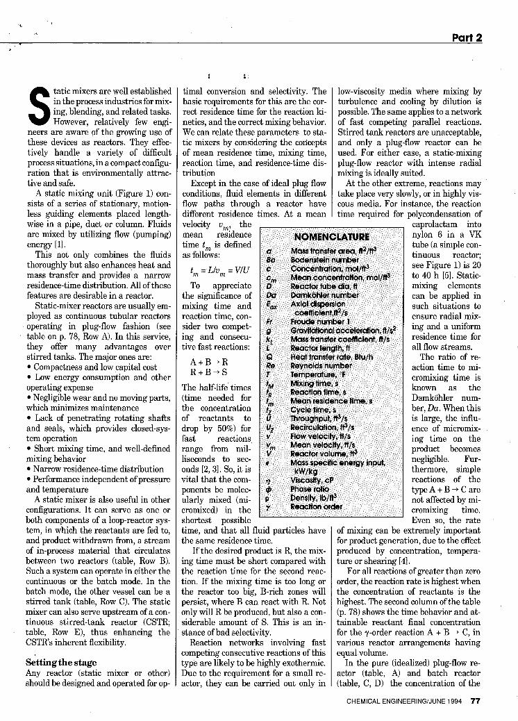
FIGURE 1. The heart of any static-mixing reactor, such as the one being as- sembled here, is its array of stationary guiding elements within the vessel
tatic mixers are well established in the process industries for mix- ing, blending, and related tasks. S However, relatively few engi-
neers are aware of the growing use of these devices as reactors. They effec- tively handle a variety of difficult process situations, in a compact configu- ration that is environmentally attrac- tive and safe.
A static mixing unit (Figure 1) con- sists of a series of stationary, motion- less guiding elements placed length- wise in a pipe, duct or column. Fluids are mixed by utilizing flow (pumping) energy [ll.
This not only combines the fluids thoroughly but also enhances heat and mass transfer and provides a narrow residence-time distribution. All of these features are desirable in a reactor.
Static-mixer reactors are usually em- ployed as continuous tubular reactors operating in plug-flow fashion (see table on p. 78, Row A). In this service, they offer many advantages over stirred tanks. The major ones are:
Compactness and low capital cost Low energy consumption and other
operating expense Negligible wear and no moving parts,
which minimizes maintenance Lack of penetrating rotating shafts
and seals, which provides closed-sys- tem operation
Short mixing time, and well-defined mixing behavior
Narrow residence-time distribution Performance independent of pressure
and temperature A static mixer is also useful in other
configurations. It can serve as one or both components of a loop-reactor sys- tem, in which the reactants are fed to, and product withdrawn from, a stream of in-process material that circulates between two reactors (table, Row B). Such a system can operate in either the continuous or the batch mode. In the batch mode, the other vessel can be a stirred tank (table, Row C). The static mixer can also serve upstream of a con- tinuous stirred-tank reactor (CSTR table, Row E), thus enhancing the CSTRs inherent flexibility.
Setting the stage Any reactor (static mixer or other) should be designed and operated for op-
: :,
timal conversion and selectivity. The basic requirements for this are the cor- rect residence time for the reaction ki- netics, and the correct mixing behavior. We can relate these parameters to sta- tic mixers by considering the concepts of mean residence time, mixing time, reaction time, and residence-time dis- tribution
Except in the case of ideal plug flow conditions, fluid elements in different flow paths through a reactor have different residence times. At a mean velocity vml the mean residence time t , is defined as follows:
tm = Llu, = VIU To appreciate
the significance of mixing time and reaction time, con- sider two compet- ing and consecu- tive fast reactions:
A + B + R R + B + S
The half-life times (time needed for the concentration of reactants to drop by 50%) for fast reactions range from mil- liseconds to sec- onds [2,3]. so, it is vital that the com- ponents be molec- ularly mixed (mi- Eromixed) in the shortest possible time, and that all fluid particles have the same residence time.
If the desired product is R, the mix- ing time must be short compared with the reaction time for the second reac- tion. If the mixing time is too long or the reactor too big, B-rich zones will persist, where B can react with R. Not mly will R be produced, but also a con- siderable amount of s. This is an in- stance of bad selectivity.
Reaction networks involving fast :ompeting consecutive reactions of this type are likely to be highly exothermic. Due to the requirement for a small re- xtor, they can be carried out only in
low-viscosity media where mixing by turbulence and cooling by dilution is possible. The same applies to a network of fast competing parallel reactions. Stirred tank reactors are unacceptable, and only a plug-flow reactor can be used. For either case, a static-mixing plug-flow reactor with intense radial mixing is ideally suited.
At the other extreme, reactions may take place very slowly, or in highly vis- cous media. For instance, the reaction time required for polycondensation of
caprolactam into nylon 6 in a VK tube (a simple con- tinuous reactor; see Figure 1) is 20 to 40 h [51. Static- mixing elements can be applied in such situations to ensure radial mix- ing and a uniform residence time for all flow streams.
The ratio of re- action time to mi- cromixing time is known as the Damkohler num- ber, Da. When this is large, the influ- ence of micromix- ing time on the product becomes negligible. Fur- thermore, simple reactions of the type A + B + C are not affected by mi- cromixing time. Even so, the rate
of mixing can be extremely important for product generation, due to the effect produced by concentration, tempera- ture or shearing [41.
For all reactions of greater than zero order, the reaction rate is highest when the concentration of reactants is the highest. The second column of the table (p. 78) shows the time behavior and at- tainable reactant final concentration for the ?-order reaction A + B + C, in various reactor arrangements having equal volume.
In the pure (idealized) plug-flow re- actor (table, A) and batch reactor (table, C, D) the concentration of the
CHEMICAL ENGINEERING/JUNE 1994 77

FEATURE REPORT LEE GLYN
Residence Time Distribution for
A
B
C
D
E
Re actor TvDe
Reactant Concentration
a
C
B
R = UJU
A
B C
V
1 .o - C CO
0.5
0 a, 0 1 2 3 4 5 6
1 .o - C CO
0.5
0.1 42 0 1 I ut, 0 1 2 3 4 5 6
0.8 - C CO
A t B + C Y = Reaction Order
0.6
0.4
0.2
0 a, 0 1 2 3 4 5 6
0 1 I ut, 0 1 2 3 4 5 6
Pulse Tracer Response
3
2 - C CO
1
0
'T 2 f,=V/U,
- C
cm 1
0- a, 0 1
01 t 0
1.ox
0.37 g00.5Lam 0 0 1 2 3
Static-mixer reactors can be employed in various configurations (Rows A, B, C and E), including combinations with continuously stirred tank reactors (Rows C and E). Each produces particular reactant-concentration and residence-time-distribution patterns
78 CHEMICAL ENGINEERING/JUNE 1994
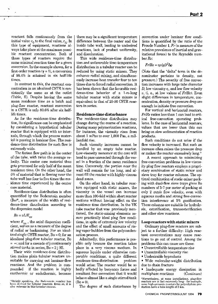
reactant falls continuously from the initial value co to the final value, ck In this type of equipment, reactions al- ways take place at the maximum possi- ble reactant concentration. Both of these types of reactors require the same minimal reaction time for a given conversion. In the example shown, for a first-order reaction (y = l), a conversion of 98.4% is attained in six half-life times.
In contrast to this, the reactant con- centration in an idealized CSTR is con- sistently the same as at the outlet (Table, E). Despite having the same mean residence time as a batch and plug-flow reactor, reactant conversion in a CSTR is only 80.6% after six half- life times.
As for the residence-time distribu- tion, its significance can be emphasized by considering a hypothetical tubular reactor that is equipped with no inter- nals, through which the process mater- ial is passing in laminar flow. The resi- dence-time distribution for such flow is extremely wide.
The fastest flow path is in the center of the tube, with twice the average ve- locity. This center core material thus gets processed for only half of the mean residence time. On the other hand, the 5% of material that is flowing near the tube wall has four to five times the res- idence time experienced by the center .core material.
Residence-time distribution is often quantified by the Bodenstein number (Bo)", a measure of the width of resi- dence-time distribution according to the dispersion model
BO = uLIE, where E,, , the axial dispersion coeffi- cient, serves as a measure of the degree of radial or backmixing. For an ideal- ized single CSTR reactor, Bo = 0; for an idealized plug-flow tubular reactor, Bo = m; and for a cascade of j continuously stirred tanks in series, Bo = 2 j 161.
Their wide residence-time distribu- tion makes plain tubular reactors un- suitable for carrying out laminar-flow reactions. And the problem is com- pounded if the reaction is highly exothermic or endothermic, because
Strictly speaking, the Bodenstein number has been derived for tubular reactors Even so, it is also relevant in this broader context
there may be a significant temperature difference between the center and the inside tube wall, leading to undesired reactions, lack of product uniformity, and discoloration.
This wide residence-time distribu- tion and unfavorable time-temperature distribution in a tubular reactor can be reduced by using static mixers. They enhance radial mixing, and simultane- ously increase heat transfer four to ten times due to forced radial convection. It has been shown that the favorable resi- dence-time behavior of a 1-m-long tubular reactor with static mixers is equivalent to that of 25-50 CSTR reac- tors in series.
Residence-time disturbance The residence-time distribution may change during the course of a reaction. During many polymerization reactions, for instance, the viscosity rises from about 1 mPas to over 1,000 Pas, a mil- lionfold rise.
Such viscosity increases cannot be handled by an empty tube reactor. Low-viscosity monomer at the core will tend to pass unreacted through the ves- sel in a fraction of the mean residence time. Conversely, the portion near the wall will remain far too long, and al- most fill the reactor with highly viscous dead zones.
On the other hand, in tubular reac- tors equipped with static mixers, the viscosity in the vessel can increase more than 100-fold within short reactor sections without having effect on the residence time distribution. In the VK tube reactor that was previously men- tioned, the static-mixing elements as- sure practically ideal plug flow condi- tions, in spite of extremely low velocity and the effect of small amounts of ris- ing vapor bubbles from the polyconden- sation process.
Admittedly, this performance is pos- sible only because the reaction takes place in a very viscous medium. In aqueous liquids under otherwise com- parable conditions, a quite different residence-time-distribution problem would arise: The reactor would be so badly affected by buoyancy forces and resultant free convection that it would behave almost like a single stirred tank (BO = 0).
The degree of such disturbance by
convection under laminar flow condi- tions is quantified by the ratio of the Froude Number 1, Fr (a measure of the relative prevalence of inertial and grav- itational forces) to the Reynolds num- ber Re:
FrlRe = q ulgD2Ap
(Note that the "delta" term in the de- nominator pertains to density, not pressure.) The severity of free convec- tion increases with large tube diameter 0, low viscosity q, and low flow velocity u, (i. e., at low values of FrlRe). Even slight differences in temperature, con- centration, density or pressure drop are enough to initiate free convection.
For vertical and horizontal reactors, FrlRe ratios less than 1 can lead to crit- ical free-convection operating prob- lems. In the case of horizontal reactors, values that are lower than this can bring on slow sedimentation of reaction products.
Such conditions do not arise if the flow velocity is increased. But such an increase often raises the pressure drop or makes the reactor excessively long.*
A recent approach to minimizing free-convection problems in low-viscos- ity plug flow reactors employs a propri- etary combination of static mixer and sieve tray for reactor columns. The op- timal combination of static-mixer pack- ing with dual-flow sieve trays gives Bo numbers of 5-7 per meter of packing at Dnly 2 mmls flow velocity, even with aqueous media and strong free-convec- tion interference at 5% gasification. These columns are suitable for hydroly- sis, esterification, transesterification and other slow reactions.
Loop reactors with static mixers Ordinary plug-flow reactors are sub-
iect to a further difficulty: High reac- tant concentrations may cause reac- tions to go out of control. Among the problems this can cause are these:
Uncontrollable temperature rise Uncontrollable viscosity rise Undesirable byproducts Wide molecular-weight distribution
3ue to chain fracture Inadequate energy dissipation in
multiphase reactions (Continues) "Nevertheless, a t some installations, plug-flow "eactors are in fact extremely long-for example, jome high-pressure reactors for polyethylene pro- luction have a tube length of 2 km.
CHEMICAL ENGINEERINGNUNE 1994 79

FEATURE REPORT
FIQURE 2. Proprietary design of this static-mixer reactor features mixing elements (right) that are not plates, but instead hollow tubes through which a heat-transfer fluid flows. One advantage is the heat removal offered for highly exothermic reactions
Excessive mixing time Inadequate shear rate An attractive solution in such cases
is to link a pair of static mixers as a loop reactor (table, B). The residence- time, mixing and heat-transfer behav- ior of this type of reactor can be ad- justed practically without limit by varying the number of mixing ele- ments, their length-to-diameter ratios, the number of feed points and the recir- culation rate. This approach is also an- other solution to the aforementioned problems involving low flow velocity or inordinate reactor lengths.
When operating at less than design throughput, loop reactors are easily controlled by adjusting the recircula- tion rate. And unlike plug-flow reac- tors, loop reactors can also be conve- niently operated on an intermittent basis.
The reactant concentration at all points in the loop reactor is slightly higher than in a CSTR, but much lower than in a plug-flow reactor. The conver- sion of the loop reactor shown in the table in Row B is 5% higher than that of the corresponding CSTR with the same reactor volume (table, Row E).
The third column of the table shows the residence-time-distribution charac-
80 CHEMICAL ENGINEERING/JUNE 1994
teristics of a loop reactor in batch (Row C) or continuous ( Row B) operation as function of Bo number in the loop. The loop residence-time distribution at low Bo number (i.e., a short loop) or short cycle time tz is practically the same as in a CSTR. The concentrations throughout the reactor are immedi- ately balanced.
At high Bo number (a long loop with static mixers), the loop behaves like a series of ideal plug-flow reactors, with individual response functions. This can be a disadvantage with extremely fast reactions, because axial temperature or concentration differences build up in the loop and take a long time to dis- perse. In such cases, the reactants should be fed at several points along the loop. The combination with a stirred tank, shown in Row E of the table, offers the high flexibility of a stirred tank as well as the advantages of a static mixer.
Exothermic-heat transfer Reactors that are assigned to carry out exothermic reactions under isothermal operating conditions must be capable of very good heat transfer through the vessel wall per unit of vessel volume. Unfortunately, this capability becomes
more and more difficult to realize as re- actor size increases.
Thus, small diameter plug-flow reac- tors used in pilot plants in most cases do not incur heat-transfer problems. However, the heat-transfer surface per unit reactor volume and the heat trans- fer coefficient both decrease with in- creasing diameter. So, the heat-trans- fer capacity of most reactors falls off rapidly with increasing volume). The resulting problem is especially acute under laminar flow conditions with vis- cous substances.
A frequent strategy with highly exothermic reactions is to employ mul- titube heat exchangers, thus obtaining large surface-to-volume ratios. But the flow must be suitably divided among the parallel tubes (often a large num- ber of them).
In some cases, this multitube ap- proach is feasible. In other situations, the likelihood of flow-distribution prob- lems (some of these subject to aggrava- tion by the ongoing reaction itself) make the use of multitube reactors dif- ficult, risky or dangerous [ l l l . Among these situations are:
Gas-liquid reactions Polymerizations Reactions with phase or viscosity
changes To deal with such cases, a patented
static-mixer reactor has been devel- oped (Figure 2). Its flow-guiding ele- ments are arranged in the same way as the crossbars of the static mixer shown in Figure 1. However, instead of being constructed with solid plates, its mix- ing elements consist of tubes through which a heat transfer fluid flows.
As a result, there are hardly any temperature or radial concentration differences. The heat-transfer capacity is very high, and is nearly constant re- gardless of reactor diameter.
Heterogeneous reactions In heterogeneous reactions (gas-liq-
uid, liquid-liquid, liquid-solid or gas- solid), the mass transfer rate between phases is often more critical than the reaction rate itself. Mass transfer is de- termined not only by the reactants characteristics, but also by the mass- specific energy input E, flow velocity and pressure drop.
According to turbulence theory,

FEATURE REPORT Part*2
changes in drop or bubble size are pro- portionate to E - O . ~ . The specific mass transfer area a depends on the bubble size and on the dispersed phase ratio I$. At the same time, the mass transfer co- efficient kL increases with increasing energy input.
Liquid-liquid and gas-liquid systems are overned by the relationship kLalI$ w [141. With low energy consump- tion (natural circulation), k,a values of 0.1-1 s-l are attainable, whereas forced circulation using in-line mixers can achieve values of 10-100 s-l, in aqueous media.
High viscosity is often linked with high mass concentration, which strongly reduces gas solubility. With increasing viscosity q, mass transfer decreases rapidly as a function of q -0.7 [151. This resistance to mass transfer must be overcome through high energy input or dilution.
One way to supply energy effectively is via a loop reactor outfitted with static mixers. In one such application com- mercialized a few years ago, a propri- etary organic liquid is contacted with oxygen in a closed loop system (no vent- ing of gas) involving high viscosities around 60 cP. The strongly exothermic reaction must take place isothermally, at 9°C. “his process yields an interme- diate product important for pharma- ceutical use.
For safety reasons, the amount of re- actants and hence the reactor volume must be small. In addition, the reactor must be able to absorb the entire heat of reaction (until the reaction is com- pleted) if the cooling or reactor recircu- lation systems fails. The residence time required for this mass-transfer-limited reaction must be reduced to less than 60 min by high energy input.
A forced-circulation loop with the aforementioned patented mixer reac- tors and static mixer-dispersers pro- vides the necessary mixing time and the mass and heat transfer capacities. “his reaction was first carried out suc- cessfully in a mini-pilot plant, using a reactor of nominal 80 mm dia. The sub- sequent full-scale plant with 450-mm- dia reactors has been operating trou- blefree since 1991 1161.
Similar loop reactors are in service as fermenters for viscoelastic biopoly- mer solutions. In such biological
82 CHEMICAL ENGINEERING/JUNE 1994
processes, the heat of reaction is gener- ally slight and mixing elements with- out internal cooling can be used. Bio- logical systems often employ solid-liquid fluidized bed reactors with immobilized enzymes. Installing static mixer packings in these fluidized beds can significantly increase the space- time yield. In one situation involving the hydrolysis of lactose, it rose by a factor of 2.7 [171.
Heterogeneous reactions also arise during chemical or petrochemical process-gas treatment, such as the se- lective absorption of hydrogen sulfide from natural gas. Acid gases and liquors react rapidly in static mixers, with residence times much under 1 s.
In these cases, the gas is the continu- ous phase while the liquid is atomized. Installation of a static mixer after the atomizing stage allows more-intensive contact between the phases, as well as high turbulence and high relative ve- locity.
The static mixers generate a liquid film on their surface, as well as a flow of
fine droplets. The reaction takes place in the liquid film on the static mixing elements and in the droplets.
Static mixers are also in widespread service as plug-flow or loop reactors, or gas-liquid contactors, in processes in- volving oxidation, chlorination, hydro- genation, alkylation or phosgenation. In these cases, the gas is the dispersed phase.
A very recent innovation is the use of static mixing elements as the support structure for heterogeneous catalysis of gases (for removal of NOx, and for pro- duction of phthalic anhydride) or liq- uids (bubble columns for hydration and for reactive distillation). The combina- tion of mixer structure and catalyst- combines the advantages of static mix- ers with the effect of conventional catalysts. Compared with dumped packings, the pressure drop is low and the radial mixing effect high. Com- pared with parallel channel structures, the mass transfer values are four to five
Edited by Nicholas P. Chopey times larger [191.
References 1. Sulzer Mixing and Reaction Technology, No.
23.27.06.40 (19911 2. Schiitz, J., Chem. Eng. Science 43 (19881, No. 8,
p. 1975-1980 3. Bourne, J.R. Proceedings of 7th Europ. Conf.
on Mixing (19911, Brugge, p. 67-75 4. Meyer, T., Renken, A,, Chem. Eng. Science 43
(19901, No. 8, p. 2793-2800 5. Muschelknautz, E., Rink, N., Chem.-Ing.-Tech.
48 (19761, 6, S. 503-512 6. Levenspiel, O., Chem. Reaction Eng., John
Wiley Verlag, N.Y. 7. Juvet, J.E., Renken, A,, Proceedings of 7th
Europ. Conf. on Mixing (19911, Brugge, p. 607- 614
9. Streiff, F.A., “Warmeubertragung bei der Kun- ststoffaufbereitung,” VDI-Verlag, Dusseldorf (19861
9. Flaschel, E., Nguyen, K.T., Renken, A,, Pro- ceedings of 5th Europ. Conf. on Mixing (19851, Wiirzburg, p. 549-554.
10. Schneider, G., Verfahrenstechnik 23 (1989),9, p. 109-112
11. Nguyen, K.T., Streiff, F., Faschel, E., Renken, E., Chem. Eng. Technol. 13 (19901, p. 214-220
12. Streiff, F.A., “Mischen van Kunststoff-u. Kautschukprodukten” VDI-Ges. Kunst- stofiechnik, Dusseldorf (1991)
13. Tauscher, W., Techn. Rundschau Sulzer 2/1991, p. 21-25
14. Streiff, F.A., Kfiser, Proceedings of 7th Enrop. Conf. on Mixing (19911, Brugge, p. 525
15. Deckwer, W.D. et al, Chem.-Ing. Tech. 60
16. Unternaher, Schauglas, Werkzeitung Ciba-
17. Renken, A, Chem.-hg.-Tech. 54 (19821, 1, p.
18. Grosz-Roell, F., Maugweiler, W., Chemie-
(19881, 5, p. 407-410
Geigy, Nr. 2, (19911
54-56
Technik 17 (19881,9, p. 115-121 19. Stringaro, J.P., and Luder, J., Chemical
PZants and Processing, July 1992, p. 6-10.
The authors James A. Rogers is Techni- cal Manager of Reaction and Extraction Technologies for the Static Mixing Group of Koch Engineering Co., Inc., P. 0. Box 8127, Wichita, KS 67208-0127; Tel. (316) 832- 5270. He was previously a re- 9onal sales manager and an inside sales engineer for Koch. Last year, he received a mas- ter’s degree in chemical engi- neering from the U. of Houston : his B.S. in chem- ical en3neering is from the U. of Oklahoma
F.A. Streiff is manager of de- velopment and process engi- neering in Mixing and Reac- tion Technology for Sulzer Chemtech Ltd., CH 8404 Switzerland. Previously he was manager of research and development on static mixers for Gebr. Sulzer AG. He has also served as development engineer for the latter firm’s Boiler Dept., as well as with Brown Boveri-Sulzer Turbom lachinerv Ltd. He. holds a Dipl. Ing. degree in mechanicd engineer- ing from the Swiss Federal Institute of Technol- ogy, Zurich.

For More Information, Circle 57